EP1701675B1 - Implantable device delivery system handle and method of use - Google Patents
Implantable device delivery system handle and method of useDownload PDFInfo
- Publication number
- EP1701675B1 EP1701675B1EP05705271AEP05705271AEP1701675B1EP 1701675 B1EP1701675 B1EP 1701675B1EP 05705271 AEP05705271 AEP 05705271AEP 05705271 AEP05705271 AEP 05705271AEP 1701675 B1EP1701675 B1EP 1701675B1
- Authority
- EP
- European Patent Office
- Prior art keywords
- tubular member
- outer tubular
- stent
- release
- relative
- Prior art date
- Legal status (The legal status is an assumption and is not a legal conclusion. Google has not performed a legal analysis and makes no representation as to the accuracy of the status listed.)
- Expired - Lifetime
Links
- 238000000034methodMethods0.000titleclaimsabstractdescription13
- 230000000087stabilizing effectEffects0.000claimsdescription23
- 230000007246mechanismEffects0.000claimsdescription10
- 230000008878couplingEffects0.000abstractdescription5
- 238000010168coupling processMethods0.000abstractdescription5
- 238000005859coupling reactionMethods0.000abstractdescription5
- 230000003287optical effectEffects0.000abstractdescription3
- 230000002441reversible effectEffects0.000abstractdescription2
- 238000009434installationMethods0.000abstract1
- 238000013152interventional procedureMethods0.000abstract1
- 239000007943implantSubstances0.000description2
- 238000003780insertionMethods0.000description2
- 230000037431insertionEffects0.000description2
- 239000000463materialSubstances0.000description2
- 230000001225therapeutic effectEffects0.000description2
- 238000004891communicationMethods0.000description1
- 239000012141concentrateSubstances0.000description1
- 238000010276constructionMethods0.000description1
- 238000013461designMethods0.000description1
- 238000005516engineering processMethods0.000description1
- 238000004519manufacturing processMethods0.000description1
- 230000000717retained effectEffects0.000description1
- 230000001954sterilising effectEffects0.000description1
- 238000004659sterilization and disinfectionMethods0.000description1
- 238000006467substitution reactionMethods0.000description1
- 238000012800visualizationMethods0.000description1
Images


Classifications
- A—HUMAN NECESSITIES
- A61—MEDICAL OR VETERINARY SCIENCE; HYGIENE
- A61F—FILTERS IMPLANTABLE INTO BLOOD VESSELS; PROSTHESES; DEVICES PROVIDING PATENCY TO, OR PREVENTING COLLAPSING OF, TUBULAR STRUCTURES OF THE BODY, e.g. STENTS; ORTHOPAEDIC, NURSING OR CONTRACEPTIVE DEVICES; FOMENTATION; TREATMENT OR PROTECTION OF EYES OR EARS; BANDAGES, DRESSINGS OR ABSORBENT PADS; FIRST-AID KITS
- A61F2/00—Filters implantable into blood vessels; Prostheses, i.e. artificial substitutes or replacements for parts of the body; Appliances for connecting them with the body; Devices providing patency to, or preventing collapsing of, tubular structures of the body, e.g. stents
- A61F2/95—Instruments specially adapted for placement or removal of stents or stent-grafts
- A61F2/9517—Instruments specially adapted for placement or removal of stents or stent-grafts handle assemblies therefor
- A—HUMAN NECESSITIES
- A61—MEDICAL OR VETERINARY SCIENCE; HYGIENE
- A61F—FILTERS IMPLANTABLE INTO BLOOD VESSELS; PROSTHESES; DEVICES PROVIDING PATENCY TO, OR PREVENTING COLLAPSING OF, TUBULAR STRUCTURES OF THE BODY, e.g. STENTS; ORTHOPAEDIC, NURSING OR CONTRACEPTIVE DEVICES; FOMENTATION; TREATMENT OR PROTECTION OF EYES OR EARS; BANDAGES, DRESSINGS OR ABSORBENT PADS; FIRST-AID KITS
- A61F2/00—Filters implantable into blood vessels; Prostheses, i.e. artificial substitutes or replacements for parts of the body; Appliances for connecting them with the body; Devices providing patency to, or preventing collapsing of, tubular structures of the body, e.g. stents
- A61F2/95—Instruments specially adapted for placement or removal of stents or stent-grafts
- A61F2/962—Instruments specially adapted for placement or removal of stents or stent-grafts having an outer sleeve
- A61F2/966—Instruments specially adapted for placement or removal of stents or stent-grafts having an outer sleeve with relative longitudinal movement between outer sleeve and prosthesis, e.g. using a push rod
Definitions
- the present inventionrelates generally to delivery systems directed to implantable medical devices and more particularly to specialized handles for allowing scope introduction and locking and one-hand implantable device placement and delivery.
- many intervention listsutilize scopes, such as bronchoscopes.
- handling the scope and the delivery cathetercan often be a clumsy process when the two devices easily disassociate from each other.
- additional personnelare required when handling the scope and the delivery catheter.
- DE-U-9209908discloses a stripper aid for helical implants, wherein a pair of slide sleeves and a stop ring are configured to slide on a guide tube to deploy the implant from a guide wire and stripper.
- WO-A-00/78246discloses a stent insertion device that includes a handle or loop for displacing an outer tubular relative to an inner tubular member to deploy a stent.
- a devicefor allowing a user to deploy a stent in an anatomical lumen of a patient as defined in claim 1.
- a stent having a proximal end and a distal endis slidably disposed in the outer tubular member, wherein the tip of the inner tubular member engages the proximal end of the stent for advancing the stent toward the distal end of the outer tubular member as the first and second release members move toward the stabilizing member.
- a method for delivering a stent in an anatomical lumen of a patient, other than on a living beingis as defined in claim 15.
- a delivery systemfor implantable devices that facilitates ease and accuracy of deployment.
- a delivery systemis provided that allows the physician to concentrate on correct placement without having to estimate extent of deployment.
- the present devicehas a physical safety mechanism that limits deployment to the critical deployment point (e.g., predetermined length proportional to the length of the implantable device being deployed).
- the critical deployment pointmay range from 5% to 95% of the implantable devices length and the optimal length is relative based on the length of the implantable device.
- the physicianis satisfied with placement, she can engages the safety means to what we refer to as the Proceed Orientation (PO) and fully deploy the implantable medical appliance.
- Alternative safety systems in accordance with the inventioninclude but are not limited to removable tab stops, ratchet incremental stops, etc., that allow for deployment and implantable device realignment along a continuum.
- Another objective of an exemplary embodiment in accordance with the present inventionis to provide a delivery system that allows for the one handed placement of large implantable devices generally and stents of about 50 mm or larger, in particular.
- Still another objective in accordance with a preferred embodiment of the present inventionis to provide a delivery device having direct visualization capabilities directly incorporated into the device by allowing for the passage of the scope through the internal diameter of the delivery device.
- Yet another objective in accordance with an exemplary embodiment of the present inventionis to provide a delivery system handle that releasably engages the scope lumen in order to provide enhanced physician control.
- preferred embodimentsfacilitate the user's ability to tighten and loosen the scope with the same hand that actuates the safety mechanism by making the respective items available to different phalanges of the users hand.
- an exemplary deployment systempreferably has one or more of the following characteristics: (1) biocompatible; (2) compliant with specialized radially expanding implantable devices; (3) capable of distal or proximal medical appliance release; (4) smooth and clean outer surface; (5) length of the device variable according to the insertion procedure to be employed; (6) outer dimension as small as possible (depends on the diameter of crimped medical appliance); (7) dimensions of the device must offer enough space for the crimped implantable devices; (8) sufficient flexibility to adapt to anatomical curvatures without loss of ability to push or pull; (9) low friction between the moving parts; (10) sufficient resistance to kinking; (11) good deployment force, ability to reposition partially deployed medical appliance; and (12) sufficiently economical to manufacture so as to make the deployment apparatus disposable.
- implantable devicesmay be broadly interpreted to include stents or other therapeutic medical appliances but are preferably devices like the Stent Technology System (STS) family of devices developed by Alveolus ® ; which includes implantable devices developed in accordance with US 2003-0024534 , US 2004/0088040 and WO 02/083037 .
- STSStent Technology System
- the preferred delivery systemis preferably formed of a material that allows for sterilization.
- the distal end of the devicemay be configured such that a portion of the distal region is removable, preferably including the distal portions of the tracks such that a housing containing additional therapeutic medical appliances can be coupled with the device to form a reloadable delivery device.
- the devicemay be reloaded with a single appliance containing distal tip, which can be screwed onto the device or coupled with the device by other conventional means.
- the preferred deviceis made of a sterilizable material that allows the device to be reused.
- the systemcomprises inner and outer tubular members that are longitudinally and axially disassociatable with respect to one another and a handle preferably coupled with a portion of the inner tubular member and that has a scope coupling mechanism.
- a slide gripis also coupled with a portion of the outer tubular member such that when the delivery system is in use the user thereof can disassociate the outer tubular member with respect to the handle and/or the inner tubular member by moving the outer tubular member distally or proximally with respect to the handle and/or inner tubular member.
- the scopecan be locked in communication with the handle by alternative means than the rotational clamp.
- a slide switch, clamp, threaded engagement or other conventional meansmay be employed.
- alternative safety mechanismsinclude but are not limited to removable tabs that couple with and are removable from the inner tubular member exposed between the slide grip and the handle body. The length of the removable tab would be roughly the length necessary to allow the outer tubular member to be retracted to the critical deployment point. In such embodiments, full deployment is achieved by removing the tab and continuing the proximal movement of the outer tubular member with respect to the handle.
- the tabmay be coupled with the tube in a reversible manner such as form fitting around a portion thereof.
- the deviceshave a similar construction as the optical, with a significantly smaller ID.
- the outer and inner tubular members specifically and the cathetergenerally incorporate many of the features of the delivery systems developed by Alveolus ® , like those disclosed in US 2004/0093056 and US 2004/0193243 .
- a principal distinction between the present catheter and that disclosed in US 2004/0093056is the substitution of the deployment system for the safety mechanism. Referring specifically to FIGS. 1-3 , it can be seen that a user of the instant device can rest her palm against the back support member 400 and retract serially the first and second release members 200 and 300.
- the order of retractionis preferably the second release member 300 then the first release member 200, however, order of retraction can vary.
- bothmay be retracted at once.
- the outer sheathis retracted and the implantable device is deployed. Because this is a proportional release system, only one release member 200 is necessary with implantable devices that are less than about 50mm. Implantable devices above this range are considered “large” or “larger” implantable devices.
- a deployment system with a single release member 200resembles that shown in FIG. 4 . In a guidewire version, the catheter dimensions would vary.
Landscapes
- Health & Medical Sciences (AREA)
- Engineering & Computer Science (AREA)
- Biomedical Technology (AREA)
- Cardiology (AREA)
- Oral & Maxillofacial Surgery (AREA)
- Transplantation (AREA)
- Heart & Thoracic Surgery (AREA)
- Vascular Medicine (AREA)
- Life Sciences & Earth Sciences (AREA)
- Animal Behavior & Ethology (AREA)
- General Health & Medical Sciences (AREA)
- Public Health (AREA)
- Veterinary Medicine (AREA)
- Prostheses (AREA)
- Media Introduction/Drainage Providing Device (AREA)
- Endoscopes (AREA)
Abstract
Description
- The present invention relates generally to delivery systems directed to implantable medical devices and more particularly to specialized handles for allowing scope introduction and locking and one-hand implantable device placement and delivery.
- Interventional practitioners, regardless of subspecialty have always had to demonstrate profound dexterity in order to effectively and accurately perform invasive procedures. This is particularly the case with the delivery and deployment of implantable devices where there is very little room for error with respect to placement. In order to assist with placement accuracy, many intervention lists utilize scopes, such as bronchoscopes. Unfortunately, handling the scope and the delivery catheter can often be a clumsy process when the two devices easily disassociate from each other. Moreover, since many delivery catheters, for one reason or another, cannot be adequately managed with one hand, additional personnel are required when handling the scope and the delivery catheter.
- Therefore, there is an existing need for an ergonomic handle specifically, and a delivery system generally, that allows a physician to deploy an implantable device with one hand. Moreover, the need remains for a delivery system that can receive a scope and lock the scope relative to the delivery system to give the physician greater control of the delivery and deployment of implantable devices.
DE-U-9209908 discloses a stripper aid for helical implants, wherein a pair of slide sleeves and a stop ring are configured to slide on a guide tube to deploy the implant from a guide wire and stripper.WO-A-00/78246 - According to the present invention, a device is provided for allowing a user to deploy a stent in an anatomical lumen of a patient as defined in claim 1.
- Preferably, a stent having a proximal end and a distal end is slidably disposed in the outer tubular member, wherein the tip of the inner tubular member engages the proximal end of the stent for advancing the stent toward the distal end of the outer tubular member as the first and second release members move toward the stabilizing member.
- Further according to the present invention, a method for delivering a stent in an anatomical lumen of a patient, other than on a living being, is as defined in claim 15.
- It is a principal purpose of the present invention to provide a delivery system for implantable devices that facilitates ease and accuracy of deployment. In accordance with an exemplary embodiment of the present invention, a delivery system is provided that allows the physician to concentrate on correct placement without having to estimate extent of deployment. In particular, in a preferred embodiment, the present device has a physical safety mechanism that limits deployment to the critical deployment point (e.g., predetermined length proportional to the length of the implantable device being deployed). The critical deployment point may range from 5% to 95% of the implantable devices length and the optimal length is relative based on the length of the implantable device. At this point, if the physician is satisfied with placement, she can engages the safety means to what we refer to as the Proceed Orientation (PO) and fully deploy the implantable medical appliance. Alternative safety systems in accordance with the invention include but are not limited to removable tab stops, ratchet incremental stops, etc., that allow for deployment and implantable device realignment along a continuum.
- Another objective of an exemplary embodiment in accordance with the present invention is to provide a delivery system that allows for the one handed placement of large implantable devices generally and stents of about 50 mm or larger, in particular.
- Still another objective in accordance with a preferred embodiment of the present invention is to provide a delivery device having direct visualization capabilities directly incorporated into the device by allowing for the passage of the scope through the internal diameter of the delivery device.
- Yet another objective in accordance with an exemplary embodiment of the present invention is to provide a delivery system handle that releasably engages the scope lumen in order to provide enhanced physician control. In line with this objective, preferred embodiments facilitate the user's ability to tighten and loosen the scope with the same hand that actuates the safety mechanism by making the respective items available to different phalanges of the users hand.
- In addition to the above objectives, an exemplary deployment system preferably has one or more of the following characteristics: (1) biocompatible; (2) compliant with specialized radially expanding implantable devices; (3) capable of distal or proximal medical appliance release; (4) smooth and clean outer surface; (5) length of the device variable according to the insertion procedure to be employed; (6) outer dimension as small as possible (depends on the diameter of crimped medical appliance); (7) dimensions of the device must offer enough space for the crimped implantable devices; (8) sufficient flexibility to adapt to anatomical curvatures without loss of ability to push or pull; (9) low friction between the moving parts; (10) sufficient resistance to kinking; (11) good deployment force, ability to reposition partially deployed medical appliance; and (12) sufficiently economical to manufacture so as to make the deployment apparatus disposable.
- Further objectives, features and advantages of the invention will be apparent from the following detailed description taken in conjunction with the accompanying drawings.
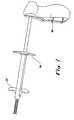
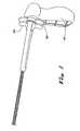
FIG. 1 shows a perspective view of the proximal region of an exemplary delivery system in accordance with the present invention showing the deployment system 100 comprising afirst release member 200 andsecond release member 300 that allow for staged release of an implantable device by proportionally retracting the outer tubular member, the deployment system 100 in a pre-deployment configuration.FIG. 2 shows a perspective view, of the proximal region ofFIG. 1 , of an exemplary delivery system in accordance with the present invention showing the deployment system 100 comprising afirst release member 200 andsecond release member 300, wherein thesecond release member 300 has been retracted proximally toward thesupport member 400 to partially deploy a large implantable device.FIG. 3 shows a perspective view, of the proximal region ofFIG. 1 , of an exemplary delivery system in accordance with the present invention showing the deployment system 100 comprising afirst release member 200 andsecond release member 300, wherein thefirst release member 200 and thesecond release member 300 have been retracted proximally toward thesupport member 400 to fully deploy a large implantable device.FIG. 4 shows the proximal region thereof. In particular, a preferred scope coupling system is shown at the proximal most area of the delivery system wherein the scope lumen feeds through into the interior of the delivery system. The coupling system in this embodiment comprises a rotationally adjustable clamp that allows for the tightening and/or loosening of the delivery system with respect to the scope. It is also shown that the outer tube, interchangeably referred to as the outer sheath, is disassociatable with respect to the handle and the inner tube such that the outer tube is a functional component of implantable device deployment. In the deliverable or commercially available configuration, the outer tube is provided at a predetermined distance distal the handle body. The predetermined distance is a function at least in part of the length of the implantable device and/or the length required to fully deploy the implantable device. Along that continuum between the handle and the slide grip of the outer tube is a point or points, short of full deployment, at which the outer tube can be retracted while allowing the physician to readjust the implantable device. As the outer sheath is retracted proximally toward the handle body, the implantable device is exposed and partially deployed. The scope coupling member is retained while providing an alternative deployment mechanism. In this embodiment, a pull handle is provided that is part of a pulley system for moving the outer tube proximally with respect to the inner tube and/or the implantable device. The outer sheath guide is provided to house the outer sheath pulley system proximal to the portion of the outer tube that is delivered into the patient.- The present invention, in a referred embodiment, provides an implantable device delivery system that allows the user to install an implantable device with one hand. Specifically, implantable devices may be broadly interpreted to include stents or other therapeutic medical appliances but are preferably devices like the Stent Technology System (STS) family of devices developed by Alveolus®; which includes implantable devices developed in accordance with
US 2003-0024534 ,US 2004/0088040 andWO 02/083037 - The distal end of the device may be configured such that a portion of the distal region is removable, preferably including the distal portions of the tracks such that a housing containing additional therapeutic medical appliances can be coupled with the device to form a reloadable delivery device. Alternatively, the device may be reloaded with a single appliance containing distal tip, which can be screwed onto the device or coupled with the device by other conventional means. In either instance, the preferred device is made of a sterilizable material that allows the device to be reused.
- In optical delivery system embodiments, the system comprises inner and outer tubular members that are longitudinally and axially disassociatable with respect to one another and a handle preferably coupled with a portion of the inner tubular member and that has a scope coupling mechanism. In certain embodiments a slide grip is also coupled with a portion of the outer tubular member such that when the delivery system is in use the user thereof can disassociate the outer tubular member with respect to the handle and/or the inner tubular member by moving the outer tubular member distally or proximally with respect to the handle and/or inner tubular member. In additional embodiments there is a distal tip coupled with the distal portion of the inner tubular member, which is at the opposite end of the inner tubular member as the handle. An advantage of certain embodiments of the present handle design is the ability to manipulate the scope (e.g., rotate) with respect to the handle when the scope and handle are engaged.
- In an embodiment not shown in
FIG. 4 , the scope can be locked in communication with the handle by alternative means than the rotational clamp. In alternative embodiments, a slide switch, clamp, threaded engagement or other conventional means may be employed. Additionally, alternative safety mechanisms include but are not limited to removable tabs that couple with and are removable from the inner tubular member exposed between the slide grip and the handle body. The length of the removable tab would be roughly the length necessary to allow the outer tubular member to be retracted to the critical deployment point. In such embodiments, full deployment is achieved by removing the tab and continuing the proximal movement of the outer tubular member with respect to the handle. The tab may be coupled with the tube in a reversible manner such as form fitting around a portion thereof. - In over the guidewire embodiments, the devices have a similar construction as the optical, with a significantly smaller ID. The outer and inner tubular members specifically and the catheter generally incorporate many of the features of the delivery systems developed by Alveolus®, like those disclosed in
US 2004/0093056 andUS 2004/0193243 . A principal distinction between the present catheter and that disclosed inUS 2004/0093056 is the substitution of the deployment system for the safety mechanism. Referring specifically toFIGS. 1-3 , it can be seen that a user of the instant device can rest her palm against theback support member 400 and retract serially the first andsecond release members second release member 300 then thefirst release member 200, however, order of retraction can vary. - Moreover, both may be retracted at once. As the
release members support member 400, the outer sheath is retracted and the implantable device is deployed. Because this is a proportional release system, only onerelease member 200 is necessary with implantable devices that are less than about 50mm. Implantable devices above this range are considered "large" or "larger" implantable devices. A deployment system with asingle release member 200 resembles that shown inFIG. 4 . In a guidewire version, the catheter dimensions would vary.
Claims (20)
- A device for allowing a user to deploy a stent in an anatomical lumen of a patient, the stent deployment device comprising:a stabilizing member (400);a longitudinally extending outer tubular member having distal and proximal ends;a longitudinally extending inner tubular member having distal and proximal ends, the distal end of the inner tubular member comprising a tip, the inner tubular member coupled with the stabilizing member and at least a portion of the inner tubular member disposed within the outer tubular member such that the inner tubular member is longitudinally and axially displaceable relative to the outer tubular member; anda deployment mechanism (200, 300) coupled with the outer tubular member,characterised in thatthe deployment mechanism comprises a first (200) and a second (300) release member operably connected to one another such that the release members are configured to be retracted proximally relative to the inner tubular member to proportionally retract the outer tubular member to allow for a staged release of the stent, andthe release members are configured to be serially retracted such that retracting the second release member moves the first release member and the outer tubular member toward the stabilizing member in order to partially deploy the stent and retracting the first release member moves the first release member and the outer tubular member relative to the second release member toward the stabilizing member in order to fully deploy the stent.
- The stent deployment device as recited in claim 1, wherein the second release member (300) is operably connected to the first release member (200) for moving the first release member and the outer tubular member in a direction toward the stabilizing member from a first position of the outer tubular member relative to the inner tubular member to a second position of the outer tubular member relative to the inner tubular member.
- The stent deployment device as recited in claim 2, wherein the first release member is movable relative to the second release member for moving the first release member and the outer tubular member in a direction toward the stabilizing member from the second position of the outer tubular member relative to the inner tubular member to a third position of the outer tubular member relative to the inner tubular member.
- The stent deployment device as recited in claim 1, 2 or 3, further comprising a safety member for preventing movement of the second release member and the outer tubular member toward the stabilizing member beyond a predetermined position of the outer tubular member relative to the inner tubular member.
- The stent deployment device as recited in claim 4, wherein movement of the second release member from a first position of the outer tubular member relative to the inner tubular member to the predetermined position is adapted to partially expose the stent.
- The stent deployment device as recited in claim 5, wherein the portion of the stent exposed is from about 5% to about 95% of the length of the stent.
- The stent deployment device as recited in claim 4, 5 or 6, wherein the safety member comprises a removable tab disposed between the stabilizing member and the outer tubular member.
- The stent deployment device as recited in any preceding claim, further comprising an elongated viewing device having a proximal end and distal end, the viewing device slidably disposed in the outer tubular member such that the proximal end of the viewing device extends outwardly of the proximal end of the outer tubular member.
- The stent deployment device as recited in claim 8, further comprising means for releasably securing the viewing device with respect to the outer tubular member.
- The stent deployment device as recited in claim 9, wherein the viewing device securing means is associated with the stabilizing member.
- The stent deployment device as recited in claim 10, wherein the viewing device securing means comprises a clamp threadably receiving in the stabilizing member.
- The stent deployment device as recited in claim 1, further comprising:a stent having a proximal end and a distal end and slidably disposed in the outer tubular member;wherein the tip of the inner tubular member engages the proximal end of the stent for advancing the stent toward the distal end of the outer tubular member as the first and second release members move toward the stabilizing member.
- The stent delivery system as recited in claim 12, wherein the second release member is operably connected to the first release member for moving the first release member and the outer tubular member in a direction toward the stabilizing member from a first position of the outer tubular member relative to the inner tubular member to a second position of the outer tubular member relative to the inner tubular member, wherein a portion of the stent is exposed outwardly of the distal end of the outer tubular member.
- The stent delivery system as recited in claim 13, wherein the first release member is movable relative to the second release member for moving the first release member and the outer tubular member in a direction toward the stabilizing member from the second position of the outer tubular member relative to the inner tubular member to a third position of the outer tubular member relative to the inner tubular member for deploying the stent from the distal end of the outer tubular member.
- A method for delivering a stent in an anatomical lumen of a patient other than when performed on a living being, the method of stent delivery comprising the steps of:providing a delivery device including a stabilizing member (400), a longitudinally extending outer tubular member having distal and proximal ends, a longitudinally extending inner tubular member having distal and proximal ends, the distal end of the inner tubular member comprising a tip, the inner tubular member coupled with the stabilizing member and at least a portion of the inner tubular member disposed within the outer tubular member such that the inner tubular member is longitudinally and axially displaceable relative to the outer tubular member, and a deployment mechanism coupled with the outer tubular member, the deployment mechanism comprising a first (200) and a second (300) release member operably connected to one another such that the release members are configured to be retracted proximally relative to the inner tubular member to proportionally retract the outer tubular member to allow for a staged release of the stent, and the release members are configured to be serially retracted such that retracting the second release member moves the first release member and the outer tubular member toward the stabilizing member in order to partially deploy the stent and retracting the first release member moves the first release member and the outer tubular member relative to the second release member toward the stabilizing member in order to fully deploy the stent;slidably disposing a stent having a proximal end and a distal end in the outer tubular member; andadvancing the first or second release member and the outer tubular member proximally relative to the inner tubular member in a direction toward the stabilizing member;wherein the tip of the inner tubular member engages the proximal end of the stent for advancing the stent toward the distal end of the outer tubular member as the first or second release member moves toward the stabilizing member.
- The method of stent delivery as recited in claim 15, wherein said advancing comprises advancing the second release member proximally toward the stabilizing member from a first position of the outer tubular member relative to the inner tubular member to a second position of the outer tubular member relative to the inner tubular member, wherein a portion of the stent is exposed outwardly of the distal end of the outer tubular member.
- The method of stent delivery as recited in claim 16, wherein said advancing comprises advancing the first release member and the outer tubular member proximally toward the stabilizing member from the second position of the outer tubular member relative to the inner tubular member to a third position of the outer tubular member relative to the inner tubular member for deploying the stent from the distal end of the outer tubular member.
- The method of stent delivery as recited in claim 15, 16 or 17, further comprising the step of preventing movement of the release member and the outer tubular member toward the stabilizing member beyond a predetermined position of the outer tubular member relative to the inner tubular member.
- The method of stent delivery as recited in any of claims 15 to 18, further comprising the steps of providing an elongated viewing device having a proximal end and distal end, and slidably disposing the viewing device in the outer tubular member such that the proximal end of the viewing device extends outwardly of the proximal end of the outer tubular member.
- The method of stent delivery as recited in claim 19, further comprising the step of releasably securing the viewing device with respect to the outer tubular member.
Applications Claiming Priority (2)
| Application Number | Priority Date | Filing Date | Title |
|---|---|---|---|
| US53489904P | 2004-01-08 | 2004-01-08 | |
| PCT/US2005/000515WO2005070095A2 (en) | 2004-01-08 | 2005-01-07 | Implantable device delivery system handle and method of use |
Publications (3)
| Publication Number | Publication Date |
|---|---|
| EP1701675A2 EP1701675A2 (en) | 2006-09-20 |
| EP1701675A4 EP1701675A4 (en) | 2007-05-30 |
| EP1701675B1true EP1701675B1 (en) | 2010-07-14 |
Family
ID=34806887
Family Applications (1)
| Application Number | Title | Priority Date | Filing Date |
|---|---|---|---|
| EP05705271AExpired - LifetimeEP1701675B1 (en) | 2004-01-08 | 2005-01-07 | Implantable device delivery system handle and method of use |
Country Status (8)
| Country | Link |
|---|---|
| US (1) | US8535366B2 (en) |
| EP (1) | EP1701675B1 (en) |
| JP (1) | JP5016310B2 (en) |
| AT (1) | ATE473707T1 (en) |
| AU (1) | AU2005206751A1 (en) |
| CA (1) | CA2552676A1 (en) |
| DE (1) | DE602005022267D1 (en) |
| WO (1) | WO2005070095A2 (en) |
Families Citing this family (32)
| Publication number | Priority date | Publication date | Assignee | Title |
|---|---|---|---|---|
| EP1701675B1 (en) | 2004-01-08 | 2010-07-14 | Merit Medical Systems, Inc. | Implantable device delivery system handle and method of use |
| EP1895951A1 (en) | 2005-05-13 | 2008-03-12 | Alveolus Inc. | Delivery device allowing visual inspection of an intravascular site |
| EP2366364B1 (en)* | 2006-04-27 | 2014-09-10 | Cook Medical Technologies LLC | Deploying medical implants |
| EP2313032B1 (en)* | 2008-08-19 | 2020-12-23 | Merit Medical Systems, Inc. | Delivery device with a protective member |
| US9999531B2 (en) | 2009-08-24 | 2018-06-19 | Qualimed Innovative Medizinprodukte Gmbh | Variable scale stent deployment device |
| US20120238806A1 (en) | 2009-08-24 | 2012-09-20 | Quali-Med Gmbh | Implantation system with handle and catheter and method of use thereof |
| US9439652B2 (en)* | 2009-08-24 | 2016-09-13 | Qualimed Innovative Medizinprodukte Gmbh | Implantation device with handle and method of use thereof |
| US8926693B2 (en)* | 2010-02-17 | 2015-01-06 | Medtronic, Inc. | Heart valve delivery catheter with safety button |
| US8998980B2 (en) | 2010-04-09 | 2015-04-07 | Medtronic, Inc. | Transcatheter prosthetic heart valve delivery system with recapturing feature and method |
| WO2011143474A1 (en)* | 2010-05-14 | 2011-11-17 | Medtronic Vascular Inc. | Catheter handle for prosthesis delivery system |
| EP2648654B1 (en) | 2010-12-07 | 2024-02-14 | Merit Medical Systems, Inc. | Stent delivery systems |
| US9192496B2 (en) | 2011-10-31 | 2015-11-24 | Merit Medical Systems, Inc. | Systems and methods for sheathing an implantable device |
| US9662235B2 (en) | 2012-04-04 | 2017-05-30 | Boston Scientific Scimed, Inc. | Handle for delivering medical device |
| CN107242923A (en)* | 2012-06-01 | 2017-10-13 | 阔利迈德创新医疗器械有限公司 | The implant system and its application method of with handles and conduit |
| US9883958B2 (en)* | 2012-07-16 | 2018-02-06 | Boston Scientific Scimed, Inc. | Stent delivery device |
| CN105705118B (en) | 2013-09-12 | 2018-03-30 | 波士顿科学国际有限公司 | Support with anti-displacement connector |
| US10117763B2 (en) | 2014-03-18 | 2018-11-06 | Boston Scientific Scimed, Inc. | Reduced granulation and inflammation stent design |
| WO2016054536A1 (en) | 2014-10-02 | 2016-04-07 | Boston Scientific Scimed, Inc. | Controlled ingrowth feature for antimigration |
| WO2016065086A1 (en) | 2014-10-22 | 2016-04-28 | Boston Scientific Scimed, Inc. | Stent with flexible hinge |
| WO2016073597A1 (en) | 2014-11-06 | 2016-05-12 | Boston Scientific Scimed, Inc. | Tracheal stent |
| WO2016141295A1 (en) | 2015-03-05 | 2016-09-09 | Merit Medical Systems, Inc. | Vascular prosthesis deployment device and method of use |
| US10470906B2 (en) | 2015-09-15 | 2019-11-12 | Merit Medical Systems, Inc. | Implantable device delivery system |
| AU2016355676B2 (en) | 2015-11-20 | 2018-12-13 | Cardiac Pacemakers, Inc. | Delivery devices and methods for leadless cardiac devices |
| WO2017087675A1 (en) | 2015-11-20 | 2017-05-26 | Cardiac Pacemakers, Inc. | Delivery devices and methods for leadless cardiac devices |
| CN115054413A (en) | 2016-09-29 | 2022-09-16 | 美国医疗设备有限公司 | Method of adjusting effective length of stent and prosthesis delivery catheter assembly |
| AU2017371223B2 (en) | 2016-12-09 | 2023-04-27 | Zenflow, Inc. | Systems, devices, and methods for the accurate deployment of an implant in the prostatic urethra |
| US11628078B2 (en) | 2017-03-15 | 2023-04-18 | Merit Medical Systems, Inc. | Transluminal delivery devices and related kits and methods |
| EP4467111A3 (en) | 2017-03-15 | 2025-03-05 | Merit Medical Systems, Inc. | Transluminal stents |
| USD836194S1 (en) | 2017-03-21 | 2018-12-18 | Merit Medical Systems, Inc. | Stent deployment device |
| WO2021146021A1 (en) | 2020-01-13 | 2021-07-22 | Boston Scientific Scimed, Inc. | Anti-migration stent |
| EP4185239A4 (en) | 2020-07-24 | 2024-08-07 | Merit Medical Systems, Inc. | ESOPHAGEAL STENT PROSTHESES AND RELATED METHODS |
| CA3194910A1 (en) | 2020-10-26 | 2022-05-05 | Tiffany ETHRIDGE | Esophageal stents with helical thread |
Citations (2)
| Publication number | Priority date | Publication date | Assignee | Title |
|---|---|---|---|---|
| US5868755A (en)* | 1997-01-16 | 1999-02-09 | Atrion Medical Products, Inc. | Sheath retractor mechanism and method |
| WO2002087470A1 (en)* | 2001-04-30 | 2002-11-07 | Angiomed Gmbh & Co. Medizintechnik Kg | Self-expanding stent delivery device |
Family Cites Families (37)
| Publication number | Priority date | Publication date | Assignee | Title |
|---|---|---|---|---|
| SE8803444D0 (en) | 1988-09-28 | 1988-09-28 | Medinvent Sa | A DEVICE FOR TRANSLUMINAL IMPLANTATION OR EXTRACTION |
| US5591172A (en)* | 1991-06-14 | 1997-01-07 | Ams Medinvent S.A. | Transluminal implantation device |
| US5201757A (en)* | 1992-04-03 | 1993-04-13 | Schneider (Usa) Inc. | Medial region deployment of radially self-expanding stents |
| DE9209908U1 (en) | 1992-07-23 | 1992-09-17 | Neuss, Malte, Dipl.-Ing. (FH), 5300 Bonn | Stripping aid for spiral implants arranged on a guide wire |
| US5824041A (en) | 1994-06-08 | 1998-10-20 | Medtronic, Inc. | Apparatus and methods for placement and repositioning of intraluminal prostheses |
| US5683451A (en)* | 1994-06-08 | 1997-11-04 | Cardiovascular Concepts, Inc. | Apparatus and methods for deployment release of intraluminal prostheses |
| US5571168A (en) | 1995-04-05 | 1996-11-05 | Scimed Lifesystems Inc | Pull back stent delivery system |
| US6413269B1 (en)* | 2000-07-06 | 2002-07-02 | Endocare, Inc. | Stent delivery system |
| US6702846B2 (en)* | 1996-04-09 | 2004-03-09 | Endocare, Inc. | Urological stent therapy system and method |
| US6254628B1 (en) | 1996-12-09 | 2001-07-03 | Micro Therapeutics, Inc. | Intracranial stent |
| US5968052A (en) | 1996-11-27 | 1999-10-19 | Scimed Life Systems Inc. | Pull back stent delivery system with pistol grip retraction handle |
| US6143016A (en) | 1997-04-21 | 2000-11-07 | Advanced Cardiovascular Systems, Inc. | Sheath and method of use for a stent delivery system |
| US6143021A (en)* | 1998-07-10 | 2000-11-07 | American Medical Systems, Inc. | Stent placement instrument and method of assembly |
| US6093194A (en)* | 1998-09-14 | 2000-07-25 | Endocare, Inc. | Insertion device for stents and methods for use |
| US6162231A (en) | 1998-09-14 | 2000-12-19 | Endocare, Inc. | Stent insertion device |
| EP1447057A1 (en) | 1998-09-30 | 2004-08-18 | Bard Peripheral Vascular, Inc. | Delivery mechanism for implantable stent |
| US6726712B1 (en) | 1999-05-14 | 2004-04-27 | Boston Scientific Scimed | Prosthesis deployment device with translucent distal end |
| US20020193863A1 (en) | 2000-09-18 | 2002-12-19 | Endotex Interventional Systems, Inc. | Apparatus for delivering endoluminal prosthesis and methods for preparing such apparatus for delivery |
| US6428566B1 (en) | 2000-10-31 | 2002-08-06 | Advanced Cardiovascular Systems, Inc. | Flexible hoop and link sheath for a stent delivery system |
| US6926732B2 (en)* | 2001-06-01 | 2005-08-09 | Ams Research Corporation | Stent delivery device and method |
| US6866669B2 (en) | 2001-10-12 | 2005-03-15 | Cordis Corporation | Locking handle deployment mechanism for medical device and method |
| US6939352B2 (en)* | 2001-10-12 | 2005-09-06 | Cordis Corporation | Handle deployment mechanism for medical device and method |
| AU2003282886B2 (en) | 2002-09-30 | 2009-07-23 | Board Of Regents, The University Of Texas System | Stent delivery system and method of use |
| US7637934B2 (en) | 2003-03-31 | 2009-12-29 | Merit Medical Systems, Inc. | Medical appliance optical delivery and deployment apparatus and method |
| US20040267281A1 (en) | 2003-06-25 | 2004-12-30 | Eran Harari | Delivery system for self-expandable diverter |
| US7635382B2 (en)* | 2003-10-22 | 2009-12-22 | Medtronic Vascular, Inc. | Delivery system for long self-expanding stents |
| US20050125050A1 (en) | 2003-12-04 | 2005-06-09 | Wilson Cook Medical Incorporated | Biliary stent introducer system |
| US7887574B2 (en) | 2003-12-23 | 2011-02-15 | Scimed Life Systems, Inc. | Stent delivery catheter |
| EP1701675B1 (en) | 2004-01-08 | 2010-07-14 | Merit Medical Systems, Inc. | Implantable device delivery system handle and method of use |
| US20050278010A1 (en) | 2004-05-27 | 2005-12-15 | Scimed Life Systems, Inc. | Stent delivery system with imaging capability |
| US7935140B2 (en) | 2005-05-13 | 2011-05-03 | Merit Medical Systems, Inc. | Delivery device with anchoring features and associated method |
| EP1895951A1 (en) | 2005-05-13 | 2008-03-12 | Alveolus Inc. | Delivery device allowing visual inspection of an intravascular site |
| US7731654B2 (en) | 2005-05-13 | 2010-06-08 | Merit Medical Systems, Inc. | Delivery device with viewing window and associated method |
| US20070208350A1 (en) | 2006-03-06 | 2007-09-06 | Gunderson Richard C | Implantable medical endoprosthesis delivery systems |
| ES2382364T3 (en) | 2006-09-28 | 2012-06-07 | St George Medical Inc | Thoracic aortic aneurysm repair device. |
| EP2313032B1 (en) | 2008-08-19 | 2020-12-23 | Merit Medical Systems, Inc. | Delivery device with a protective member |
| US9192496B2 (en) | 2011-10-31 | 2015-11-24 | Merit Medical Systems, Inc. | Systems and methods for sheathing an implantable device |
- 2005
- 2005-01-07EPEP05705271Apatent/EP1701675B1/ennot_activeExpired - Lifetime
- 2005-01-07ATAT05705271Tpatent/ATE473707T1/ennot_activeIP Right Cessation
- 2005-01-07JPJP2006549437Apatent/JP5016310B2/ennot_activeExpired - Lifetime
- 2005-01-07WOPCT/US2005/000515patent/WO2005070095A2/enactiveApplication Filing
- 2005-01-07DEDE602005022267Tpatent/DE602005022267D1/ennot_activeExpired - Lifetime
- 2005-01-07AUAU2005206751Apatent/AU2005206751A1/ennot_activeAbandoned
- 2005-01-07CACA002552676Apatent/CA2552676A1/ennot_activeAbandoned
- 2005-01-07USUS10/585,430patent/US8535366B2/enactiveActive
Patent Citations (2)
| Publication number | Priority date | Publication date | Assignee | Title |
|---|---|---|---|---|
| US5868755A (en)* | 1997-01-16 | 1999-02-09 | Atrion Medical Products, Inc. | Sheath retractor mechanism and method |
| WO2002087470A1 (en)* | 2001-04-30 | 2002-11-07 | Angiomed Gmbh & Co. Medizintechnik Kg | Self-expanding stent delivery device |
Also Published As
| Publication number | Publication date |
|---|---|
| EP1701675A4 (en) | 2007-05-30 |
| AU2005206751A1 (en) | 2005-08-04 |
| JP2007517605A (en) | 2007-07-05 |
| WO2005070095A3 (en) | 2005-11-24 |
| ATE473707T1 (en) | 2010-07-15 |
| JP5016310B2 (en) | 2012-09-05 |
| DE602005022267D1 (en) | 2010-08-26 |
| CA2552676A1 (en) | 2005-08-04 |
| EP1701675A2 (en) | 2006-09-20 |
| US20090118740A1 (en) | 2009-05-07 |
| WO2005070095A2 (en) | 2005-08-04 |
| US8535366B2 (en) | 2013-09-17 |
Similar Documents
| Publication | Publication Date | Title |
|---|---|---|
| EP1701675B1 (en) | Implantable device delivery system handle and method of use | |
| US10137022B2 (en) | Implantation device with handle and method of use thereof | |
| US20190374750A1 (en) | Guidewire feeder | |
| US7608099B2 (en) | Medical appliance delivery apparatus and method of use | |
| US8092468B2 (en) | Deployment handle for an implant deployment device | |
| US20130035636A1 (en) | Delivery and Deployment Catheter for an Implantable Medical Device | |
| EP3570762B1 (en) | Medical device handles | |
| EP2271290A1 (en) | Implant release mechanism | |
| EP3302310B1 (en) | Snare auto micro-lock | |
| US10779977B2 (en) | Variable scale stent deployment device | |
| US6547766B1 (en) | Catheter with variable dimension guide wire lumen | |
| US11051961B2 (en) | Deployment handle with stabilizing rail for a pre-loaded prosthesis delivery device | |
| CN104334122A (en) | Implant system with handle and catheter and method of use thereof | |
| US20200093623A1 (en) | Deployment handle with stabilizing shells for a pre-loaded prosthesis delivery device | |
| EP4611695A1 (en) | Systems and methods for treatment of airway blockages | |
| GB2577307A (en) | Deployment handle with stabilizing shells for a pre-loaded prosthesis delivery device | |
| GB2576340A (en) | Deployment handle with stabilizing rail for a pre-loaded prosthesis delivery device |
Legal Events
| Date | Code | Title | Description |
|---|---|---|---|
| PUAI | Public reference made under article 153(3) epc to a published international application that has entered the european phase | Free format text:ORIGINAL CODE: 0009012 | |
| 17P | Request for examination filed | Effective date:20060711 | |
| AK | Designated contracting states | Kind code of ref document:A2 Designated state(s):AT BE BG CH CY CZ DE DK EE ES FI FR GB GR HU IE IS IT LI LT LU MC NL PL PT RO SE SI SK TR | |
| DAX | Request for extension of the european patent (deleted) | ||
| A4 | Supplementary search report drawn up and despatched | Effective date:20070504 | |
| RIC1 | Information provided on ipc code assigned before grant | Ipc:A61F 2/06 20060101AFI20070426BHEP | |
| 17Q | First examination report despatched | Effective date:20070927 | |
| RAP1 | Party data changed (applicant data changed or rights of an application transferred) | Owner name:MERIT MEDICAL SYSTEMS, INC. | |
| GRAP | Despatch of communication of intention to grant a patent | Free format text:ORIGINAL CODE: EPIDOSNIGR1 | |
| GRAS | Grant fee paid | Free format text:ORIGINAL CODE: EPIDOSNIGR3 | |
| GRAA | (expected) grant | Free format text:ORIGINAL CODE: 0009210 | |
| AK | Designated contracting states | Kind code of ref document:B1 Designated state(s):AT BE BG CH CY CZ DE DK EE ES FI FR GB GR HU IE IS IT LI LT LU MC NL PL PT RO SE SI SK TR | |
| REG | Reference to a national code | Ref country code:GB Ref legal event code:FG4D | |
| REG | Reference to a national code | Ref country code:CH Ref legal event code:EP | |
| REG | Reference to a national code | Ref country code:IE Ref legal event code:FG4D | |
| REG | Reference to a national code | Ref country code:NL Ref legal event code:T3 | |
| REF | Corresponds to: | Ref document number:602005022267 Country of ref document:DE Date of ref document:20100826 Kind code of ref document:P | |
| LTIE | Lt: invalidation of european patent or patent extension | Effective date:20100714 | |
| PG25 | Lapsed in a contracting state [announced via postgrant information from national office to epo] | Ref country code:LT Free format text:LAPSE BECAUSE OF FAILURE TO SUBMIT A TRANSLATION OF THE DESCRIPTION OR TO PAY THE FEE WITHIN THE PRESCRIBED TIME-LIMIT Effective date:20100714 Ref country code:AT Free format text:LAPSE BECAUSE OF FAILURE TO SUBMIT A TRANSLATION OF THE DESCRIPTION OR TO PAY THE FEE WITHIN THE PRESCRIBED TIME-LIMIT Effective date:20100714 Ref country code:FI Free format text:LAPSE BECAUSE OF FAILURE TO SUBMIT A TRANSLATION OF THE DESCRIPTION OR TO PAY THE FEE WITHIN THE PRESCRIBED TIME-LIMIT Effective date:20100714 | |
| PG25 | Lapsed in a contracting state [announced via postgrant information from national office to epo] | Ref country code:PT Free format text:LAPSE BECAUSE OF FAILURE TO SUBMIT A TRANSLATION OF THE DESCRIPTION OR TO PAY THE FEE WITHIN THE PRESCRIBED TIME-LIMIT Effective date:20101115 Ref country code:PL Free format text:LAPSE BECAUSE OF FAILURE TO SUBMIT A TRANSLATION OF THE DESCRIPTION OR TO PAY THE FEE WITHIN THE PRESCRIBED TIME-LIMIT Effective date:20100714 Ref country code:IS Free format text:LAPSE BECAUSE OF FAILURE TO SUBMIT A TRANSLATION OF THE DESCRIPTION OR TO PAY THE FEE WITHIN THE PRESCRIBED TIME-LIMIT Effective date:20101114 Ref country code:CY Free format text:LAPSE BECAUSE OF FAILURE TO SUBMIT A TRANSLATION OF THE DESCRIPTION OR TO PAY THE FEE WITHIN THE PRESCRIBED TIME-LIMIT Effective date:20100714 Ref country code:BG Free format text:LAPSE BECAUSE OF FAILURE TO SUBMIT A TRANSLATION OF THE DESCRIPTION OR TO PAY THE FEE WITHIN THE PRESCRIBED TIME-LIMIT Effective date:20101014 Ref country code:SI Free format text:LAPSE BECAUSE OF FAILURE TO SUBMIT A TRANSLATION OF THE DESCRIPTION OR TO PAY THE FEE WITHIN THE PRESCRIBED TIME-LIMIT Effective date:20100714 | |
| PG25 | Lapsed in a contracting state [announced via postgrant information from national office to epo] | Ref country code:SE Free format text:LAPSE BECAUSE OF FAILURE TO SUBMIT A TRANSLATION OF THE DESCRIPTION OR TO PAY THE FEE WITHIN THE PRESCRIBED TIME-LIMIT Effective date:20100714 Ref country code:GR Free format text:LAPSE BECAUSE OF FAILURE TO SUBMIT A TRANSLATION OF THE DESCRIPTION OR TO PAY THE FEE WITHIN THE PRESCRIBED TIME-LIMIT Effective date:20101015 | |
| PG25 | Lapsed in a contracting state [announced via postgrant information from national office to epo] | Ref country code:DK Free format text:LAPSE BECAUSE OF FAILURE TO SUBMIT A TRANSLATION OF THE DESCRIPTION OR TO PAY THE FEE WITHIN THE PRESCRIBED TIME-LIMIT Effective date:20100714 | |
| PLBE | No opposition filed within time limit | Free format text:ORIGINAL CODE: 0009261 | |
| STAA | Information on the status of an ep patent application or granted ep patent | Free format text:STATUS: NO OPPOSITION FILED WITHIN TIME LIMIT | |
| PG25 | Lapsed in a contracting state [announced via postgrant information from national office to epo] | Ref country code:RO Free format text:LAPSE BECAUSE OF FAILURE TO SUBMIT A TRANSLATION OF THE DESCRIPTION OR TO PAY THE FEE WITHIN THE PRESCRIBED TIME-LIMIT Effective date:20100714 Ref country code:EE Free format text:LAPSE BECAUSE OF FAILURE TO SUBMIT A TRANSLATION OF THE DESCRIPTION OR TO PAY THE FEE WITHIN THE PRESCRIBED TIME-LIMIT Effective date:20100714 Ref country code:CZ Free format text:LAPSE BECAUSE OF FAILURE TO SUBMIT A TRANSLATION OF THE DESCRIPTION OR TO PAY THE FEE WITHIN THE PRESCRIBED TIME-LIMIT Effective date:20100714 Ref country code:SK Free format text:LAPSE BECAUSE OF FAILURE TO SUBMIT A TRANSLATION OF THE DESCRIPTION OR TO PAY THE FEE WITHIN THE PRESCRIBED TIME-LIMIT Effective date:20100714 | |
| 26N | No opposition filed | Effective date:20110415 | |
| PG25 | Lapsed in a contracting state [announced via postgrant information from national office to epo] | Ref country code:ES Free format text:LAPSE BECAUSE OF FAILURE TO SUBMIT A TRANSLATION OF THE DESCRIPTION OR TO PAY THE FEE WITHIN THE PRESCRIBED TIME-LIMIT Effective date:20101025 | |
| REG | Reference to a national code | Ref country code:DE Ref legal event code:R097 Ref document number:602005022267 Country of ref document:DE Effective date:20110415 | |
| PG25 | Lapsed in a contracting state [announced via postgrant information from national office to epo] | Ref country code:MC Free format text:LAPSE BECAUSE OF NON-PAYMENT OF DUE FEES Effective date:20110131 | |
| REG | Reference to a national code | Ref country code:CH Ref legal event code:PL | |
| REG | Reference to a national code | Ref country code:IE Ref legal event code:MM4A | |
| PG25 | Lapsed in a contracting state [announced via postgrant information from national office to epo] | Ref country code:LI Free format text:LAPSE BECAUSE OF NON-PAYMENT OF DUE FEES Effective date:20110131 Ref country code:CH Free format text:LAPSE BECAUSE OF NON-PAYMENT OF DUE FEES Effective date:20110131 | |
| PG25 | Lapsed in a contracting state [announced via postgrant information from national office to epo] | Ref country code:IE Free format text:LAPSE BECAUSE OF NON-PAYMENT OF DUE FEES Effective date:20110107 | |
| PG25 | Lapsed in a contracting state [announced via postgrant information from national office to epo] | Ref country code:LU Free format text:LAPSE BECAUSE OF NON-PAYMENT OF DUE FEES Effective date:20110107 | |
| PG25 | Lapsed in a contracting state [announced via postgrant information from national office to epo] | Ref country code:TR Free format text:LAPSE BECAUSE OF FAILURE TO SUBMIT A TRANSLATION OF THE DESCRIPTION OR TO PAY THE FEE WITHIN THE PRESCRIBED TIME-LIMIT Effective date:20100714 | |
| PG25 | Lapsed in a contracting state [announced via postgrant information from national office to epo] | Ref country code:HU Free format text:LAPSE BECAUSE OF FAILURE TO SUBMIT A TRANSLATION OF THE DESCRIPTION OR TO PAY THE FEE WITHIN THE PRESCRIBED TIME-LIMIT Effective date:20100714 | |
| REG | Reference to a national code | Ref country code:FR Ref legal event code:PLFP Year of fee payment:12 | |
| REG | Reference to a national code | Ref country code:FR Ref legal event code:PLFP Year of fee payment:13 | |
| REG | Reference to a national code | Ref country code:FR Ref legal event code:PLFP Year of fee payment:14 | |
| PGFP | Annual fee paid to national office [announced via postgrant information from national office to epo] | Ref country code:NL Payment date:20221220 Year of fee payment:19 Ref country code:GB Payment date:20221208 Year of fee payment:19 Ref country code:FR Payment date:20221208 Year of fee payment:19 | |
| PGFP | Annual fee paid to national office [announced via postgrant information from national office to epo] | Ref country code:BE Payment date:20221216 Year of fee payment:19 | |
| PGFP | Annual fee paid to national office [announced via postgrant information from national office to epo] | Ref country code:IT Payment date:20221213 Year of fee payment:19 Ref country code:DE Payment date:20221207 Year of fee payment:19 | |
| P01 | Opt-out of the competence of the unified patent court (upc) registered | Effective date:20230521 | |
| REG | Reference to a national code | Ref country code:DE Ref legal event code:R119 Ref document number:602005022267 Country of ref document:DE | |
| REG | Reference to a national code | Ref country code:NL Ref legal event code:MM Effective date:20240201 | |
| GBPC | Gb: european patent ceased through non-payment of renewal fee | Effective date:20240107 | |
| PG25 | Lapsed in a contracting state [announced via postgrant information from national office to epo] | Ref country code:DE Free format text:LAPSE BECAUSE OF NON-PAYMENT OF DUE FEES Effective date:20240801 | |
| PG25 | Lapsed in a contracting state [announced via postgrant information from national office to epo] | Ref country code:GB Free format text:LAPSE BECAUSE OF NON-PAYMENT OF DUE FEES Effective date:20240107 | |
| PG25 | Lapsed in a contracting state [announced via postgrant information from national office to epo] | Ref country code:BE Free format text:LAPSE BECAUSE OF NON-PAYMENT OF DUE FEES Effective date:20240131 | |
| PG25 | Lapsed in a contracting state [announced via postgrant information from national office to epo] | Ref country code:FR Free format text:LAPSE BECAUSE OF NON-PAYMENT OF DUE FEES Effective date:20240131 | |
| PG25 | Lapsed in a contracting state [announced via postgrant information from national office to epo] | Ref country code:NL Free format text:LAPSE BECAUSE OF NON-PAYMENT OF DUE FEES Effective date:20240201 | |
| PG25 | Lapsed in a contracting state [announced via postgrant information from national office to epo] | Ref country code:NL Free format text:LAPSE BECAUSE OF NON-PAYMENT OF DUE FEES Effective date:20240201 Ref country code:GB Free format text:LAPSE BECAUSE OF NON-PAYMENT OF DUE FEES Effective date:20240107 Ref country code:FR Free format text:LAPSE BECAUSE OF NON-PAYMENT OF DUE FEES Effective date:20240131 Ref country code:DE Free format text:LAPSE BECAUSE OF NON-PAYMENT OF DUE FEES Effective date:20240801 Ref country code:BE Free format text:LAPSE BECAUSE OF NON-PAYMENT OF DUE FEES Effective date:20240131 | |
| REG | Reference to a national code | Ref country code:BE Ref legal event code:MM Effective date:20240131 | |
| PG25 | Lapsed in a contracting state [announced via postgrant information from national office to epo] | Ref country code:IT Free format text:LAPSE BECAUSE OF NON-PAYMENT OF DUE FEES Effective date:20240107 |