EP1699507B1 - Contrast container holder and method to fill syringes - Google Patents
Contrast container holder and method to fill syringesDownload PDFInfo
- Publication number
- EP1699507B1 EP1699507B1EP04813537.0AEP04813537AEP1699507B1EP 1699507 B1EP1699507 B1EP 1699507B1EP 04813537 AEP04813537 AEP 04813537AEP 1699507 B1EP1699507 B1EP 1699507B1
- Authority
- EP
- European Patent Office
- Prior art keywords
- syringe
- contrast media
- filling
- injector
- fill
- Prior art date
- Legal status (The legal status is an assumption and is not a legal conclusion. Google has not performed a legal analysis and makes no representation as to the accuracy of the status listed.)
- Expired - Lifetime
Links
- 238000000034methodMethods0.000titleclaimsdescription26
- 229940039231contrast mediaDrugs0.000claimsdescription49
- 239000002872contrast mediaSubstances0.000claimsdescription49
- 239000012530fluidSubstances0.000claimsdescription23
- 230000008878couplingEffects0.000claims1
- 238000010168coupling processMethods0.000claims1
- 238000005859coupling reactionMethods0.000claims1
- 238000002347injectionMethods0.000description11
- 239000007924injectionSubstances0.000description11
- 239000000463materialSubstances0.000description6
- 238000005273aerationMethods0.000description4
- 238000013461designMethods0.000description3
- 230000008859changeEffects0.000description2
- 238000004140cleaningMethods0.000description2
- 230000001276controlling effectEffects0.000description2
- 230000000694effectsEffects0.000description2
- 238000005429filling processMethods0.000description2
- 238000003384imaging methodMethods0.000description2
- 238000009434installationMethods0.000description2
- 238000012544monitoring processMethods0.000description2
- 229920003023plasticPolymers0.000description2
- 239000004033plasticSubstances0.000description2
- 230000008569processEffects0.000description2
- 230000001360synchronised effectEffects0.000description2
- XAGFODPZIPBFFR-UHFFFAOYSA-NaluminiumChemical compound[Al]XAGFODPZIPBFFR-UHFFFAOYSA-N0.000description1
- 229910052782aluminiumInorganic materials0.000description1
- 230000036760body temperatureEffects0.000description1
- 239000000919ceramicSubstances0.000description1
- 230000001419dependent effectEffects0.000description1
- 238000001514detection methodMethods0.000description1
- 238000003745diagnosisMethods0.000description1
- 238000002059diagnostic imagingMethods0.000description1
- 230000000977initiatory effectEffects0.000description1
- 230000003993interactionEffects0.000description1
- 238000011835investigationMethods0.000description1
- 238000002595magnetic resonance imagingMethods0.000description1
- 238000004519manufacturing processMethods0.000description1
- 238000012986modificationMethods0.000description1
- 230000004048modificationEffects0.000description1
- 238000009206nuclear medicineMethods0.000description1
- 238000012634optical imagingMethods0.000description1
- 230000001105regulatory effectEffects0.000description1
- 230000004044responseEffects0.000description1
- 229910001220stainless steelInorganic materials0.000description1
- 239000010935stainless steelSubstances0.000description1
- 239000000126substanceSubstances0.000description1
- 230000001225therapeutic effectEffects0.000description1
- 230000007704transitionEffects0.000description1
- 238000012285ultrasound imagingMethods0.000description1
Images


Classifications
- A—HUMAN NECESSITIES
- A61—MEDICAL OR VETERINARY SCIENCE; HYGIENE
- A61M—DEVICES FOR INTRODUCING MEDIA INTO, OR ONTO, THE BODY; DEVICES FOR TRANSDUCING BODY MEDIA OR FOR TAKING MEDIA FROM THE BODY; DEVICES FOR PRODUCING OR ENDING SLEEP OR STUPOR
- A61M5/00—Devices for bringing media into the body in a subcutaneous, intra-vascular or intramuscular way; Accessories therefor, e.g. filling or cleaning devices, arm-rests
- A61M5/007—Devices for bringing media into the body in a subcutaneous, intra-vascular or intramuscular way; Accessories therefor, e.g. filling or cleaning devices, arm-rests for contrast media
- A—HUMAN NECESSITIES
- A61—MEDICAL OR VETERINARY SCIENCE; HYGIENE
- A61M—DEVICES FOR INTRODUCING MEDIA INTO, OR ONTO, THE BODY; DEVICES FOR TRANSDUCING BODY MEDIA OR FOR TAKING MEDIA FROM THE BODY; DEVICES FOR PRODUCING OR ENDING SLEEP OR STUPOR
- A61M5/00—Devices for bringing media into the body in a subcutaneous, intra-vascular or intramuscular way; Accessories therefor, e.g. filling or cleaning devices, arm-rests
- A61M5/14—Infusion devices, e.g. infusing by gravity; Blood infusion; Accessories therefor
- A61M5/142—Pressure infusion, e.g. using pumps
- A61M5/145—Pressure infusion, e.g. using pumps using pressurised reservoirs, e.g. pressurised by means of pistons
- A61M5/1452—Pressure infusion, e.g. using pumps using pressurised reservoirs, e.g. pressurised by means of pistons pressurised by means of pistons
- A61M5/14546—Front-loading type injectors
- A—HUMAN NECESSITIES
- A61—MEDICAL OR VETERINARY SCIENCE; HYGIENE
- A61M—DEVICES FOR INTRODUCING MEDIA INTO, OR ONTO, THE BODY; DEVICES FOR TRANSDUCING BODY MEDIA OR FOR TAKING MEDIA FROM THE BODY; DEVICES FOR PRODUCING OR ENDING SLEEP OR STUPOR
- A61M2209/00—Ancillary equipment
- A61M2209/08—Supports for equipment
- A61M2209/082—Mounting brackets, arm supports for equipment
- A—HUMAN NECESSITIES
- A61—MEDICAL OR VETERINARY SCIENCE; HYGIENE
- A61M—DEVICES FOR INTRODUCING MEDIA INTO, OR ONTO, THE BODY; DEVICES FOR TRANSDUCING BODY MEDIA OR FOR TAKING MEDIA FROM THE BODY; DEVICES FOR PRODUCING OR ENDING SLEEP OR STUPOR
- A61M5/00—Devices for bringing media into the body in a subcutaneous, intra-vascular or intramuscular way; Accessories therefor, e.g. filling or cleaning devices, arm-rests
- A61M5/14—Infusion devices, e.g. infusing by gravity; Blood infusion; Accessories therefor
- A61M5/142—Pressure infusion, e.g. using pumps
- A61M5/145—Pressure infusion, e.g. using pumps using pressurised reservoirs, e.g. pressurised by means of pistons
- A61M5/1452—Pressure infusion, e.g. using pumps using pressurised reservoirs, e.g. pressurised by means of pistons pressurised by means of pistons
- A61M5/14566—Pressure infusion, e.g. using pumps using pressurised reservoirs, e.g. pressurised by means of pistons pressurised by means of pistons with a replaceable reservoir for receiving a piston rod of the pump
- A—HUMAN NECESSITIES
- A61—MEDICAL OR VETERINARY SCIENCE; HYGIENE
- A61M—DEVICES FOR INTRODUCING MEDIA INTO, OR ONTO, THE BODY; DEVICES FOR TRANSDUCING BODY MEDIA OR FOR TAKING MEDIA FROM THE BODY; DEVICES FOR PRODUCING OR ENDING SLEEP OR STUPOR
- A61M5/00—Devices for bringing media into the body in a subcutaneous, intra-vascular or intramuscular way; Accessories therefor, e.g. filling or cleaning devices, arm-rests
- A61M5/178—Syringes
- A61M5/1782—Devices aiding filling of syringes in situ
Definitions
- the present inventionrelates to injectors for injecting fluid into patients.
- a medical fluidis injected into a patient during diagnosis or treatment.
- a medical fluidis injected into a patient during diagnosis or treatment.
- One exampleis the injection of contrast media into a patient to improve Optical Imaging, Nuclear Medicine, CT, Angiographic, Magnetic Resonance or Ultrasound imaging, or any diagnostic imaging or therapeutic application using a powered, automatic injector.
- injectors suitable for these and similar applicationstypically must use a relatively large volume syringe and be capable of producing relatively large flow rates and injection pressures. For this reason, injectors for such applications are typically motorized, and include a large, high mass injector motor and drive train. For ease of use, the motor and drive train are typically housed in an injection head, which is supported by a floor, wall, or ceiling mounted arm.
- the injection headis typically mounted on the arm in a pivotal manner, so that the head may be tilted upward (with the syringe tip above the remainder of the syringe) to facilitate filling the syringe with fluid, and downward (with the syringe tip below the remainder of the syringe) for injection. Tilting the head in this manner facilitates removal of air from the syringe during filling, and reduces the likelihood that air will be injected into the subject during the injection process. Nevertheless, the potential for accidentally injecting air into a patient remains a serious safety concern.
- injectorsinclude a separate console for controlling the injector.
- the consoletypically includes programmable circuitry which can be used for automatic, programmed control of the injector, so that the operation of the injector can be made predictable and potentially synchronized with operations of other equipment such as scanners or imaging equipment.
- One particular operational routine performed by the injector systemis that of filling the syringe with contrast.
- This filling sequence for a power injectortypically requires the use of both hands by the operator.
- a contrast containeris held in one hand in close proximity to the injector while the other hand operates the injector controls to retract the plunger so as to fill the syringe.
- injectors which can auto-fill a preset volumethe use of both hands by the operator is still required when initially starting the auto-fill sequence.
- the filling sequencecan be problematic in that if it is performed too fast, the contrast media is aerated or if it is performed too slow, the sequence can take an unreasonable amount of time to complete.
- a maximum filling rate for contrast mediathat will avoid aerating the contrast media during filling. While this speed can be programmed in the injector and automatically used, an operator typically monitors the syringe filling to further reduce the likelihood of aeration of the contrast media.
- the present inventionalso relates to a method for changing contrast media containers during a syringe filling sequence.
- the syringe filling sequence of a syringeis paused when a first contrast container is substantially emptied and the first contrast container is replaced with a second contrast container.
- substantially all airis expelled from a fill tube coupled between the syringe and the second contrast container and, thereafter, filling of the syringe from the second contrast container is resumed at a rate wherein aeration of the contrast media is prevented and wherein the rate is faster than a maximum fill rate if air is not previously expelled from the fill tube.
- an injector 20 used in accordance with the present inventionincludes various functional components, such as a power head 22, a console 24 and power pack 26 (mounted inside of a cover).
- a syringe 36( FIG. 2 ) is mounted to the injector 20 in the face plate 28 of the power head 22, and the various injector controls are used to fill the syringe with, e.g., contrast media for a CT, Angiographic or other procedure, which media is then injected into a subject under investigation under operator or pre-programmed control.
- the injector power head 22includes a hand-operated movement control lever 29 for use in controlling the movement of the internal drive motor, and a display 30 for indicating to the operator the current status and operating parameters of the injector.
- the console 24includes a touch screen display 32 which may be used by the operator to remotely control operation of the injector 20, and may also be used to specify and store programs for automatic injection by the injector 20, which can later be automatically executed by the injector upon initiation by the operator.
- Power head 22 and console 24connect through cabling (not shown) to the power pack 26.
- Power pack 26includes a power supply for the injector, interface circuitry for communicating between the console 24 and power head 22, and further circuitry permitting connection of the injector 20 to remote units such as remote consoles, remote hand or foot control switches, or other original equipment manufacturer (OEM) remote control connections allowing, for example, the operation of injector 20 to be synchronized with the x-ray exposure of an imaging system
- OEMoriginal equipment manufacturer
- Power head 22, console 24 and power pack 26are mounted to a carriage 34 which includes a support arm 35 for supporting power head 22 for easy positioning of power head 22 in the vicinity of the examination subject.
- a carriage 34which includes a support arm 35 for supporting power head 22 for easy positioning of power head 22 in the vicinity of the examination subject.
- console 24 and power pack 26may be placed on a table or mounted on an electronics rack in an examination room while power head 22 is supported by a ceiling, floor or wall mounted support arm.
- a syringe 36 and pressure jacket 38are mounted to power head 22, so that the motor internal to power head 22 may be energized to move a plunger 37 within the barrel of syringe 36 toward and away from a discharge tip 40 of the syringe, to thereby expel fluid from the syringe 36 or fill the syringe with fluid.
- Pressure jacket 38provides support to the outer walls of syringe 36 to protect the walls of syringe 36 from failure at high injection pressures.
- Syringe 36 and pressure jacket 38are made of a clear plastic material through which the operator can view the current location of plunger 37 and any fluid or air in the syringe between plunger 37 and discharge tip 40. Accordingly, as described above, an operator may tilt power head 22 upward, fill syringe 36 from a source of fluid while visually monitoring the filling process, then connect the injector to tubing leading to the patient, expel air from the tubing and syringe while visually monitoring the level of fluid in the syringe, and then once air has been expelled, tilt the injector downward and proceed to inject fluid into a subject.
- power head 22includes the hand-operated movement control, which is in the form of the rotatable lever 29.
- lever 29is rotatable on an axis of rotation inside of power head 22.
- the hand-operated control lever 29When the hand-operated control lever 29 is left in its home position, illustrated in FIG. 2 , no plunger motion is generated by power head 22.
- hand-operated control lever 29is rotated toward syringe 36, forward plunger motion is generated by power head 22, expelling fluid or air from syringe 36.
- hand-operated control lever 29is rotated away from syringe 36, reverse plunger motion is generated by power head 22, filling syringe 36 with fluid or air.
- a heater blanket 42is installed abutting the exterior wall of pressure jacket 38.
- Heater blanket 42includes an electrical heater which generates heat for regulating the temperature of fluid within syringe 36.
- Heater blanket 42is mounted to a post 44 extending from face plate 28, holding heater blanket 42 in thermal contact with pressure jacket 38.
- an indicator lamp 46(covered by a light-diffusing cover) which indicates the status of the power head.
- One particular operational routine typically performed using an injector systemis that of filling the syringe 36 with contrast media.
- This filling sequence for a power injectortypically requires the use of both hands by the operator.
- a contrast containeris held in one hand in close proximity to the injector while the other hand operates the injector controls to retract the plunger so as to fill the syringe.
- injectors which can auto-fill a preset volumethe use of both hands by the operator is still required when initially starting the auto-fill sequence. Accordingly, a need exists to simplify the syringe sequence in power injectors so that an operator can have at least one hand available to perform other activities while filling a syringe.
- one exemplary answer for addressing this needis utilization of a contrast container holder that attaches to a portion of the injector head 22 and secures the container in an orientation conducive to filling the syringe.
- the material for this container holdercan be any of a variety of suitable materials which are sufficiently rigid to support the weight of a typical contrast container.
- Preferable materialsinclude plastics, stainless steel, aluminum and certain ceramics. Each of these materials can also withstand sufficient moisture, chemicals and temperature to easily permit cleaning of the holder by a variety of methods. Additionally, the material of the holder is such that it does not unreasonably contribute to breaking or damaging the contrast container but still functions in an environment in which it will likely receive numerous impacts of various severity.
- FIG. 3A particular exemplary design for a contrast container holder is illustrated in FIG. 3 ; however, one of ordinary skill would appreciate that other functionally equivalent designs are contemplated within the scope of the present invention.
- the container holderhas a receptacle 502, 506 connected with a portion 44 of the injector housing and adapted for holding the contrast container 504 so that a fill tube 510 can easily reach the entire contrast container.
- FIG. 3illustrates a two piece container holder having an upper, curved arm 502 that curls around the contrast container 504 while a lower arm 506 supports the container 504 from underneath. The two arms 502 and 506 work in conjunction to hold the container 504 titled toward the injector head 22.
- the exemplary holder 502, 506features an open design that facilitates the securing and removing of a contrast container 504 using only one hand. While an operator can, of course, use two hands to insert and remove the container 504, it is not necessary. One hand operation is particularly useful when an operator must replace a container during a filling sequence.
- a fill tube 510can bridge from the syringe 36 to the bottom of the container 504.
- Typical fill tubesare 20,32cm (8 inches) long but other lengths could be accommodated if desired.
- contrast container holder 502, 506tilts the container 504 towards the fill tube 510 when the injector head 22 is appropriately oriented to perform a filling sequence.
- U.S. Pat. No. 5,868,710describes in detail one exemplary system for properly orienting an injector head during filling.
- the containercan not be titled so much towards the injector head 22 that contrast fluid leaks out and neither can the tilt be so slight that it prevents the fill tube 510 from reaching the bottom of the container 504. If the fill tube 510 is unable to reach the bottom of the container 504, then the contrast fluid cannot be fully removed from the container 504.
- FIG. 3depicts the exemplary container holder 502, 506 attached to the heater jacket 44
- the container holder 502, 506can be coupled with the injector head 22 in a number of ways.
- the holdercan mount or clip on the underside of the injector head housing, or even the faceplate.
- the holdercan attach to the post which holds the heater blanket.
- the container holderinstalls on the injector similar to the manner in which the heater blanket attaches.
- the holdercan snap over a mounting post for convenient installation and permit tool-free removal for cleaning or other operating sequences of the injector that do not require the presence of a container.
- the holdercan also be hinged such that it remains substantially permanently attached to the injector head but can fold out of the way so as to not interfere with other operating sequences or with storing the injector.
- the attachment of the container holder with the injectorshould allow tool-free attaching and removing so as not to further burden the operators with difficult and time-consuming tasks.
- FIG. 4illustrates an alternative embodiment, in which the container 504 is held in a cage 602.
- the cageis connected to a support arm 604 through hinges 606 (only one hinge is visible in this perspective view).
- the exemplary hinges 606can be protrusions that loosely fit into an eye portion of the support arm 604. As the injector is rotated to orient it for filling, the hinges 606 ensure that the container 504 is properly oriented with respect to the injector head 22.
- the support arm 604can be adapted to fit within an opening 610 in the injector or its faceplate.
- a locking know 608can be used that frictionally engages the support arm 604 within the opening 610, when tightened.
- FIG. 5illustrates a clamping alternative for holding the contrast container.
- the holderincludes two semi-rigid arms 702 that fit around, for example, the pressure sleeve of the injector head 22.
- the holderalso includes a basket portion 704 that is integrally formed with the arms 702 or otherwise attached thereto. By tightening the knob 706, the arms 702 are flexed inward and securely grip the pressure sleeve during the filling sequence.
- FIG. 6illustrates another type of removable container holder.
- This holderutilizes a bracket 802 that is affixed to the injector head housing 22.
- This bracket 802can also be integrally formed with the housing during its manufacture.
- the holderincludes an arm portion 804 that transitions to a circular opening 808 to hold the contrast container 504.
- a flange 806is positioned under the circular opening 808 to prevent the container from falling through.
- the flange 806could be annular or straight (as shown in the figure) and can reach fully across the opening 808 or only reach part of the way.
- the filling sequencecan be problematic in that if it is performed too fast, the contrast media is aerated or if it is performed too slow, the sequence can take an unreasonable amount of time to complete.
- operatorstry to perform the filling at a maximum filling rate for contrast media that will avoid aerating the contrast media. This rate is partly dependent on the contrast media, its viscosity and the possible presence of air in the fill tube. While this speed can be programmed in the injector and automatically used, an operator typically monitors the syringe filling to further reduce the likelihood of aeration of the contrast media.
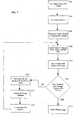
- step 902is to enter a desired fill volume. Once this value is entered, the user can initiate, in step 904, the start of the auto-fill sequence. In response, the injector system will slowly pull, in step 906, a small volume of contrast into the syringe while the syringe is pointing substantially upwards.
- An injector headthat is oriented so as to have the syringe positioned above the opposite end of the head and to be tilted 45 degrees or less from vertical is considered to be pointing substantially upwards; however, a tilt angle less than 20 degrees is preferable.
- the small volume of contrast fluid that is pulled into the syringe at a slow enough rate so as not to aerate the fluidis a volume sufficient to be visibly noticed by the operator performing the filling sequence and is usually at least 20 ml.
- the injector systemautomatically (or the operator, manually) reverses the direction of the injector ram, in step 908, so that the contrast fluid is expelled from the syringe.
- the ramis operated such that at least a portion of the fluid in the syringe travels through the fill tube and re-enters the contrast container. Thus, all air is expelled from the fill tube and syringe.
- the injector systemcan energize the ram, in step 910, to pull back the programmed volume with a reduced risk of introducing bubbles due to aeration.
- the rate at which the contrast media can now be pulled backis faster than if the air had not been previously expelled from the fill tube and syringe as in step 908.
- a similar techniquecan be used to change bottles of contrast media during a filling sequence when the contrast remaining in a container is insufficient to provide the volume of contrast media needed to correctly fill a syringe.
- This techniqueis illustrated as steps 912 -920 of the flowchart of FIG. 7 .
- This techniqueis useful by itself as a way to change contrast containers during a filling sequence or can be part of an automatic filling sequence as shown in FIG. 7 .
- the contrast containermay be emptied, in step 912, and air introduced into the fill tube while acquiring the final amount from the container.
- the operatorcan pause the filling sequence, in step 916, using the operator interface of the injector system.
- the ramis stopped so that the empty container can be replaced in step 918 with a new container having contrast media.
- the fill sequencecan then be restarted in step 920 by the operator.
- the ramautomatically operates in the opposite direction to push air out of the fill tube and syringe. Expulsion of all air from the system, in step 908, is ensured by operating the ram in this direction until contrast fluid from the syringe re-enters the new container.
- the ram directioncan be reversed to pull up the contrast media, in step 910, so as to fill the syringe.
- the rate at which the contrast media can now be pulled backis faster than if the air had not been expunged. With the new contrast container available the filling of the syringe can be completed in step 914.
- routine of FIG. 7can be automated such that when the operator has replaced the contrast container and instructs the injector system to continue or resume the filling sequence, the injector can control the ram direction and speed to automatically expel sufficient media to ensure the fill tube is cleared of air and then automatically reverse the ram so as to draw more contrast media in at the faster rate.
Landscapes
- Health & Medical Sciences (AREA)
- Vascular Medicine (AREA)
- Engineering & Computer Science (AREA)
- Anesthesiology (AREA)
- Biomedical Technology (AREA)
- Heart & Thoracic Surgery (AREA)
- Hematology (AREA)
- Life Sciences & Earth Sciences (AREA)
- Animal Behavior & Ethology (AREA)
- General Health & Medical Sciences (AREA)
- Public Health (AREA)
- Veterinary Medicine (AREA)
- Infusion, Injection, And Reservoir Apparatuses (AREA)
- Apparatus For Radiation Diagnosis (AREA)
Description
- The present invention relates to injectors for injecting fluid into patients.
- In many medical environments, a medical fluid is injected into a patient during diagnosis or treatment. One example is the injection of contrast media into a patient to improve Optical Imaging, Nuclear Medicine, CT, Angiographic, Magnetic Resonance or Ultrasound imaging, or any diagnostic imaging or therapeutic application using a powered, automatic injector.
- Injectors suitable for these and similar applications typically must use a relatively large volume syringe and be capable of producing relatively large flow rates and injection pressures. For this reason, injectors for such applications are typically motorized, and include a large, high mass injector motor and drive train. For ease of use, the motor and drive train are typically housed in an injection head, which is supported by a floor, wall, or ceiling mounted arm.
- The injection head is typically mounted on the arm in a pivotal manner, so that the head may be tilted upward (with the syringe tip above the remainder of the syringe) to facilitate filling the syringe with fluid, and downward (with the syringe tip below the remainder of the syringe) for injection. Tilting the head in this manner facilitates removal of air from the syringe during filling, and reduces the likelihood that air will be injected into the subject during the injection process. Nevertheless, the potential for accidentally injecting air into a patient remains a serious safety concern.
- In addition to the injection head discussed above, many injectors include a separate console for controlling the injector. The console typically includes programmable circuitry which can be used for automatic, programmed control of the injector, so that the operation of the injector can be made predictable and potentially synchronized with operations of other equipment such as scanners or imaging equipment.
- One particular operational routine performed by the injector system is that of filling the syringe with contrast. This filling sequence for a power injector typically requires the use of both hands by the operator. A contrast container is held in one hand in close proximity to the injector while the other hand operates the injector controls to retract the plunger so as to fill the syringe. Even in injectors which can auto-fill a preset volume, the use of both hands by the operator is still required when initially starting the auto-fill sequence.
- Accordingly, a need exists to simplify the syringe sequence in power injectors so that an operator can have at least one hand available to perform other activities during the entire operation of filling a syringe.
- Occasionally when filling a syringe, the filling sequence can be problematic in that if it is performed too fast, the contrast media is aerated or if it is performed too slow, the sequence can take an unreasonable amount of time to complete. There is, therefore, based on the contrast media and the possible presence of air in the fill tube, a maximum filling rate for contrast media that will avoid aerating the contrast media during filling. While this speed can be programmed in the injector and automatically used, an operator typically monitors the syringe filling to further reduce the likelihood of aeration of the contrast media. A need exists for a filling sequence that permits filling of the syringe with contrast fluid faster than the maximum filling speed attainable if air is present in the fill tube.
- A prior art medical injector system is disclosed in
WO 02/04049 A1 - Those needs identified above and other problems of conventional injector systems are addressed by embodiments of the present invention that perform a filling sequence without aerating the contrast media during filling.
- According to the present invention there is provided a method for performing a filling sequence in a contrast media injector system according to claim 1.
- The present invention also relates to a method for changing contrast media containers during a syringe filling sequence. In accordance with this aspect, the syringe filling sequence of a syringe is paused when a first contrast container is substantially emptied and the first contrast container is replaced with a second contrast container. Next, substantially all air is expelled from a fill tube coupled between the syringe and the second contrast container and, thereafter, filling of the syringe from the second contrast container is resumed at a rate wherein aeration of the contrast media is prevented and wherein the rate is faster than a maximum fill rate if air is not previously expelled from the fill tube.
FIG. 1 illustrates a perspective view of an injector in accordance with principles of the present invention, including a power head, console, and power pack (under a cover), with the syringe, pressure jacket, heater blanket and air detection module removed.FIG. 2 illustrates a perspective view of the power head of the injector ofFIG. 1 with a pressure jacket, syringe and heater blanket mounted thereto, showing the power head display, hand-operated control, and support arm mounting in greater detail.FIG. 3 illustrates a contrast container holder.FIG. 4 illustrate a contrast container holder.FIG. 5 illustrates a contrast container holder.FIG. 6 illustrates a contrast container holder.FIG. 7 illustrates a flowchart of an exemplary method for filling a syringe using an injector system, according to the present invention.- Referring to
FIG. 1 , aninjector 20 used in accordance with the present invention includes various functional components, such as apower head 22, a console 24 and power pack 26 (mounted inside of a cover). A syringe 36 (FIG. 2 ) is mounted to theinjector 20 in theface plate 28 of thepower head 22, and the various injector controls are used to fill the syringe with, e.g., contrast media for a CT, Angiographic or other procedure, which media is then injected into a subject under investigation under operator or pre-programmed control. - The
injector power head 22 includes a hand-operatedmovement control lever 29 for use in controlling the movement of the internal drive motor, and adisplay 30 for indicating to the operator the current status and operating parameters of the injector. The console 24 includes a touch screen display 32 which may be used by the operator to remotely control operation of theinjector 20, and may also be used to specify and store programs for automatic injection by theinjector 20, which can later be automatically executed by the injector upon initiation by the operator. Power head 22 and console 24 connect through cabling (not shown) to the power pack 26. Power pack 26 includes a power supply for the injector, interface circuitry for communicating between the console 24 andpower head 22, and further circuitry permitting connection of theinjector 20 to remote units such as remote consoles, remote hand or foot control switches, or other original equipment manufacturer (OEM) remote control connections allowing, for example, the operation ofinjector 20 to be synchronized with the x-ray exposure of an imaging systemPower head 22, console 24 and power pack 26 are mounted to acarriage 34 which includes asupport arm 35 for supportingpower head 22 for easy positioning ofpower head 22 in the vicinity of the examination subject. Other installations are also contemplated however; for example, console 24 and power pack 26 may be placed on a table or mounted on an electronics rack in an examination room whilepower head 22 is supported by a ceiling, floor or wall mounted support arm.- Referring now to
FIG. 2 , in operation, asyringe 36 andpressure jacket 38 are mounted topower head 22, so that the motor internal topower head 22 may be energized to move aplunger 37 within the barrel ofsyringe 36 toward and away from a discharge tip 40 of the syringe, to thereby expel fluid from thesyringe 36 or fill the syringe with fluid.Pressure jacket 38 provides support to the outer walls ofsyringe 36 to protect the walls ofsyringe 36 from failure at high injection pressures. - Syringe 36 and
pressure jacket 38 are made of a clear plastic material through which the operator can view the current location ofplunger 37 and any fluid or air in the syringe betweenplunger 37 and discharge tip 40. Accordingly, as described above, an operator may tiltpower head 22 upward, fillsyringe 36 from a source of fluid while visually monitoring the filling process, then connect the injector to tubing leading to the patient, expel air from the tubing and syringe while visually monitoring the level of fluid in the syringe, and then once air has been expelled, tilt the injector downward and proceed to inject fluid into a subject. - To facilitate this filling process, and other operations that may be performed during injection of a subject,
power head 22 includes the hand-operated movement control, which is in the form of therotatable lever 29. Specifically,lever 29 is rotatable on an axis of rotation inside ofpower head 22. When the hand-operatedcontrol lever 29 is left in its home position, illustrated inFIG. 2 , no plunger motion is generated bypower head 22. However, when hand-operatedcontrol lever 29 is rotated towardsyringe 36, forward plunger motion is generated bypower head 22, expelling fluid or air fromsyringe 36. Alternatively, when hand-operatedcontrol lever 29 is rotated away fromsyringe 36, reverse plunger motion is generated bypower head 22, fillingsyringe 36 with fluid or air. - To ensure that fluid injected into a subject is maintained at approximately body temperature, a
heater blanket 42 is installed abutting the exterior wall ofpressure jacket 38.Heater blanket 42 includes an electrical heater which generates heat for regulating the temperature of fluid withinsyringe 36.Heater blanket 42 is mounted to apost 44 extending fromface plate 28, holdingheater blanket 42 in thermal contact withpressure jacket 38. - At the rear end of
power head 22 is an indicator lamp 46 (covered by a light-diffusing cover) which indicates the status of the power head. - Further details of exemplary hardware and software which control operation of an injector system such as that illustrated in
FIGS. 1 and2 can be found inU.S. Pat. No. 5,868,710 . - One particular operational routine typically performed using an injector system is that of filling the
syringe 36 with contrast media. This filling sequence for a power injector typically requires the use of both hands by the operator. A contrast container is held in one hand in close proximity to the injector while the other hand operates the injector controls to retract the plunger so as to fill the syringe. Even with injectors which can auto-fill a preset volume, the use of both hands by the operator is still required when initially starting the auto-fill sequence. Accordingly, a need exists to simplify the syringe sequence in power injectors so that an operator can have at least one hand available to perform other activities while filling a syringe. - In particular, one exemplary answer for addressing this need is utilization of a contrast container holder that attaches to a portion of the
injector head 22 and secures the container in an orientation conducive to filling the syringe. - The material for this container holder can be any of a variety of suitable materials which are sufficiently rigid to support the weight of a typical contrast container. Preferable materials include plastics, stainless steel, aluminum and certain ceramics. Each of these materials can also withstand sufficient moisture, chemicals and temperature to easily permit cleaning of the holder by a variety of methods. Additionally, the material of the holder is such that it does not unreasonably contribute to breaking or damaging the contrast container but still functions in an environment in which it will likely receive numerous impacts of various severity.
- A particular exemplary design for a contrast container holder is illustrated in
FIG. 3 ; however, one of ordinary skill would appreciate that other functionally equivalent designs are contemplated within the scope of the present invention. The container holder has areceptacle portion 44 of the injector housing and adapted for holding thecontrast container 504 so that afill tube 510 can easily reach the entire contrast container. More particularly,FIG. 3 illustrates a two piece container holder having an upper,curved arm 502 that curls around thecontrast container 504 while alower arm 506 supports thecontainer 504 from underneath. The twoarms container 504 titled toward theinjector head 22. - The
exemplary holder contrast container 504 using only one hand. While an operator can, of course, use two hands to insert and remove thecontainer 504, it is not necessary. One hand operation is particularly useful when an operator must replace a container during a filling sequence. - Another feature of the
holder container 504 in proximity to thesyringe tip 508 so that afill tube 510 can bridge from thesyringe 36 to the bottom of thecontainer 504. Typical fill tubes are 20,32cm (8 inches) long but other lengths could be accommodated if desired. - Yet another feature of the
contrast container holder container 504 towards thefill tube 510 when theinjector head 22 is appropriately oriented to perform a filling sequence. The previously incorporatedU.S. Pat. No. 5,868,710 describes in detail one exemplary system for properly orienting an injector head during filling. - While a range of angles of tilt can be utilized for the
holder injector head 22 that contrast fluid leaks out and neither can the tilt be so slight that it prevents thefill tube 510 from reaching the bottom of thecontainer 504. If thefill tube 510 is unable to reach the bottom of thecontainer 504, then the contrast fluid cannot be fully removed from thecontainer 504. - Although
FIG. 3 depicts theexemplary container holder heater jacket 44, thecontainer holder injector head 22 in a number of ways. For example, the holder can mount or clip on the underside of the injector head housing, or even the faceplate. Also, the holder can attach to the post which holds the heater blanket. In such an instance, the container holder installs on the injector similar to the manner in which the heater blanket attaches. In particular, through a slight interference fit, the holder can snap over a mounting post for convenient installation and permit tool-free removal for cleaning or other operating sequences of the injector that do not require the presence of a container. The holder can also be hinged such that it remains substantially permanently attached to the injector head but can fold out of the way so as to not interfere with other operating sequences or with storing the injector. The attachment of the container holder with the injector should allow tool-free attaching and removing so as not to further burden the operators with difficult and time-consuming tasks. FIG. 4 illustrates an alternative embodiment, in which thecontainer 504 is held in acage 602. The cage is connected to asupport arm 604 through hinges 606 (only one hinge is visible in this perspective view). The exemplary hinges 606 can be protrusions that loosely fit into an eye portion of thesupport arm 604. As the injector is rotated to orient it for filling, thehinges 606 ensure that thecontainer 504 is properly oriented with respect to theinjector head 22.- The
support arm 604 can be adapted to fit within anopening 610 in the injector or its faceplate. To secure thesupport arm 604, a lockingknow 608 can be used that frictionally engages thesupport arm 604 within theopening 610, when tightened. FIG. 5 illustrates a clamping alternative for holding the contrast container. According to this embodiment, the holder includes twosemi-rigid arms 702 that fit around, for example, the pressure sleeve of theinjector head 22. The holder also includes abasket portion 704 that is integrally formed with thearms 702 or otherwise attached thereto. By tightening theknob 706, thearms 702 are flexed inward and securely grip the pressure sleeve during the filling sequence.FIG. 6 illustrates another type of removable container holder. This holder utilizes abracket 802 that is affixed to theinjector head housing 22. Thisbracket 802 can also be integrally formed with the housing during its manufacture. The holder includes anarm portion 804 that transitions to a circular opening 808 to hold thecontrast container 504. Aflange 806 is positioned under the circular opening 808 to prevent the container from falling through. Theflange 806 could be annular or straight (as shown in the figure) and can reach fully across the opening 808 or only reach part of the way.- The above-described embodiments of the container holder illustrate a number of features which one of ordinary skill will readily recognize can be implemented in a number of functionally equivalent ways. Thus, these embodiments are presented as examples and are not intended to limit the present invention to only the specific forms shown.
- Occasionally when filling a syringe, the filling sequence can be problematic in that if it is performed too fast, the contrast media is aerated or if it is performed too slow, the sequence can take an unreasonable amount of time to complete. When filling a syringe, operators try to perform the filling at a maximum filling rate for contrast media that will avoid aerating the contrast media. This rate is partly dependent on the contrast media, its viscosity and the possible presence of air in the fill tube. While this speed can be programmed in the injector and automatically used, an operator typically monitors the syringe filling to further reduce the likelihood of aeration of the contrast media. A need exists for a filling sequence that permits filling of the syringe with contrast fluid faster than the maximum filling speed attainable when air is in the fill tube.
- One exemplary automatic filling sequence is illustrated as a flowchart in
FIG. 7 . Of course, a user could perform a manual filling sequence as well without deviating from the scope of the present invention. The first step in an automatic filling sequence,step 902, is to enter a desired fill volume. Once this value is entered, the user can initiate, instep 904, the start of the auto-fill sequence. In response, the injector system will slowly pull, instep 906, a small volume of contrast into the syringe while the syringe is pointing substantially upwards. An injector head that is oriented so as to have the syringe positioned above the opposite end of the head and to be tilted 45 degrees or less from vertical is considered to be pointing substantially upwards; however, a tilt angle less than 20 degrees is preferable. The small volume of contrast fluid that is pulled into the syringe at a slow enough rate so as not to aerate the fluid is a volume sufficient to be visibly noticed by the operator performing the filling sequence and is usually at least 20 ml. - Once the small volume of contrast is in the syringe, the injector system automatically (or the operator, manually) reverses the direction of the injector ram, in
step 908, so that the contrast fluid is expelled from the syringe. In particular, the ram is operated such that at least a portion of the fluid in the syringe travels through the fill tube and re-enters the contrast container. Thus, all air is expelled from the fill tube and syringe. - With no air in the syringe and fill tube, the injector system can energize the ram, in
step 910, to pull back the programmed volume with a reduced risk of introducing bubbles due to aeration. The rate at which the contrast media can now be pulled back is faster than if the air had not been previously expelled from the fill tube and syringe as instep 908. - A similar technique can be used to change bottles of contrast media during a filling sequence when the contrast remaining in a container is insufficient to provide the volume of contrast media needed to correctly fill a syringe. This technique is illustrated as steps 912 -920 of the flowchart of
FIG. 7 . This technique is useful by itself as a way to change contrast containers during a filling sequence or can be part of an automatic filling sequence as shown inFIG. 7 . - During filling, the contrast container may be emptied, in
step 912, and air introduced into the fill tube while acquiring the final amount from the container. When the container is empty, the operator can pause the filling sequence, instep 916, using the operator interface of the injector system. As a result of the operator pausing the filling sequence, the ram is stopped so that the empty container can be replaced instep 918 with a new container having contrast media. - The fill sequence can then be restarted in
step 920 by the operator. Upon restart, the ram automatically operates in the opposite direction to push air out of the fill tube and syringe. Expulsion of all air from the system, instep 908, is ensured by operating the ram in this direction until contrast fluid from the syringe re-enters the new container. Once all the air is expunged, the ram direction can be reversed to pull up the contrast media, instep 910, so as to fill the syringe. The rate at which the contrast media can now be pulled back is faster than if the air had not been expunged. With the new contrast container available the filling of the syringe can be completed instep 914. - Although the description of the flowchart of
FIG. 7 includes the interaction of an operator in many steps, these processes can be automated by appropriate programming of the injector system to perform the steps without requiring the intervention of an operator. In order to program the injector system in this way, assumptions will be made about the volumetric capacity of the fill tube used between the syringe and the contrast container. Knowing this volumetric capacity will allow an automatic routine to draw enough contrast media so that a small amount reaches the syringe and to reverse the ram for a time and speed sufficient to expel contrast media to ensure all the air is successfully expunged from both the syringe and the fill tube. - Additionally, the routine of
FIG. 7 can be automated such that when the operator has replaced the contrast container and instructs the injector system to continue or resume the filling sequence, the injector can control the ram direction and speed to automatically expel sufficient media to ensure the fill tube is cleared of air and then automatically reverse the ram so as to draw more contrast media in at the faster rate. - While the present invention has been illustrated by description of various embodiments and while these embodiments have been described in considerable detail, it is not the intention of the applicant to restrict or in any way limit the scope of the claims to such detail. Additional advantages and modifications will readily appear to those skilled in the art. The invention in its broader aspect is, therefore, not limited to the specific details, representative system, apparatus, and method, and illustrative example shown and described. Accordingly, departures may be made from such details without departing from the scope of the claims.
Claims (12)
- A method for performing a filling sequence in a contrast media injector system (20) having a fill tube (510) coupling a syringe (36) to a contrast media, the method comprising the steps of:drawing contrast media from a first contrast media container (504) into the syringe (36) through the fill tube at a first fill rate;thereafter, expelling substantially all air from the fill tube (510) by expelling fluid from the syringe (36), wherein at least some of the contrast media is expelled through the fill tube (510) during the expelling;characterised by;thereafter, filling the syringe (36) at a second fill rate wherein the second fill rate is faster than the first fill rate.
- The method of claim 1, wherein the expelling is performed by the contrast media injector automatically under control of the injector system (20).
- The method of claim 1, wherein the filling is performed by the contrast media injector automatically under control of the injector system (20).
- The method of claim 1, wherein the expelling and filling are performed by the contrast media injector automatically under control of the injector system (20).
- The method of any of claims 1 to 4 further comprising:pausing the syringe filling sequence of the syringe (36) when the first contrast media container (504) is substantially emptied;replacing the first contrast media container (504) with a second contrast media container (504);expelling substantially all air from the fill tube (510) coupled between the syringe (36) and the second contrast media container (504); andthereafter, resuming filling the syringe (36) from the second contrast media container (504) at the second fill rate.
- The method of claim 5, wherein the expelling comprises expelling a portion of contrast media in the syringe (36) out of the fill tube (510) into the second contrast media container (504).
- The method of claim 5, wherein the expelling comprises expelling substantially all air from the syringe (36).
- The method of any preceding claim, wherein the step of drawing contrast media at a first fill rate includes drawing a first volume of contrast media from the first contrast media container (504) into the syringe (36), the first volume being a volume sufficient to be visibly noticed by an operator of the injector system.
- The method of claim 8, wherein the first volume is at least 20 ml.
- The method of any preceding claim, comprising the steps of:providing a contrast media injector system (20);carrying out the method of any preceding claim using the contrast media injector system (20).
- The method of claim 10, comprising the steps of:entering a desired fill volume into the contrast media injector system prior to the injector system (20) drawing contrast media at the first fill rate;wherein the step of filling the syringe (36) at the second fill rate comprises the step of filling the syringe (36) with the desired fill volume.
- The method of claim 10 or 11, wherein the syringe (36) is pointing substantially upward during the steps of:drawing contrast media at the first fill rate;expelling substantially all air from the fill tube (510); andfilling the syringe (36) at the second fill rate.
Priority Applications (1)
| Application Number | Priority Date | Filing Date | Title |
|---|---|---|---|
| EP09075325.2AEP2113269B1 (en) | 2003-12-31 | 2004-12-09 | Contrast container holder and method to fill syringes |
Applications Claiming Priority (2)
| Application Number | Priority Date | Filing Date | Title |
|---|---|---|---|
| US10/750,427US7621892B2 (en) | 2003-12-31 | 2003-12-31 | Contrast container holder and method to fill syringes |
| PCT/US2004/041225WO2005065747A2 (en) | 2003-12-31 | 2004-12-09 | Contrast container holder and method to fill syringes |
Related Child Applications (2)
| Application Number | Title | Priority Date | Filing Date |
|---|---|---|---|
| EP09075325.2ADivision-IntoEP2113269B1 (en) | 2003-12-31 | 2004-12-09 | Contrast container holder and method to fill syringes |
| EP09075325.2ADivisionEP2113269B1 (en) | 2003-12-31 | 2004-12-09 | Contrast container holder and method to fill syringes |
Publications (2)
| Publication Number | Publication Date |
|---|---|
| EP1699507A2 EP1699507A2 (en) | 2006-09-13 |
| EP1699507B1true EP1699507B1 (en) | 2015-11-11 |
Family
ID=34711276
Family Applications (2)
| Application Number | Title | Priority Date | Filing Date |
|---|---|---|---|
| EP09075325.2AExpired - LifetimeEP2113269B1 (en) | 2003-12-31 | 2004-12-09 | Contrast container holder and method to fill syringes |
| EP04813537.0AExpired - LifetimeEP1699507B1 (en) | 2003-12-31 | 2004-12-09 | Contrast container holder and method to fill syringes |
Family Applications Before (1)
| Application Number | Title | Priority Date | Filing Date |
|---|---|---|---|
| EP09075325.2AExpired - LifetimeEP2113269B1 (en) | 2003-12-31 | 2004-12-09 | Contrast container holder and method to fill syringes |
Country Status (7)
| Country | Link |
|---|---|
| US (2) | US7621892B2 (en) |
| EP (2) | EP2113269B1 (en) |
| JP (4) | JP4976137B2 (en) |
| CN (2) | CN100548397C (en) |
| CA (1) | CA2552067C (en) |
| ES (2) | ES2559424T3 (en) |
| WO (1) | WO2005065747A2 (en) |
Families Citing this family (28)
| Publication number | Priority date | Publication date | Assignee | Title |
|---|---|---|---|---|
| USD550838S1 (en)* | 2004-10-13 | 2007-09-11 | Liebel-Flarsheim Company | Power injection system face plate |
| US20060079842A1 (en)* | 2004-10-13 | 2006-04-13 | Liebel-Flarsheim Company | Powerhead control in a power injection system |
| US7507221B2 (en) | 2004-10-13 | 2009-03-24 | Mallinckrodt Inc. | Powerhead of a power injection system |
| US20090221914A1 (en)* | 2005-09-14 | 2009-09-03 | Acist Medical Systems, Inc. | Medical Fluid Injection System |
| DE102006017360A1 (en)* | 2006-04-11 | 2007-10-18 | Diasys Diagnostic Systems Gmbh | Method for dosing and mixing |
| EP2158928A2 (en)* | 2007-04-11 | 2010-03-03 | Mallinckrodt Inc. | Universal syringe |
| WO2008137375A2 (en)* | 2007-05-04 | 2008-11-13 | Mallinckrodt Inc. | Methods for controlling medical fluid injections |
| ES2391719T3 (en)* | 2007-11-19 | 2012-11-29 | Mallinckrodt Llc | Fluid delivery system with multi-dose fluid source |
| JP2012507357A (en)* | 2008-10-31 | 2012-03-29 | マリンクロッド エルエルシー | Multiple dose injection system |
| EP2456572B1 (en) | 2009-07-24 | 2014-02-26 | BAYER Medical Care Inc. | Multi-fluid medical injector system |
| US8604265B2 (en) | 2010-04-16 | 2013-12-10 | Kci Licensing, Inc. | Dressings and methods for treating a tissue site on a patient |
| US8403902B2 (en)* | 2010-05-18 | 2013-03-26 | Kci Licensing, Inc. | Reduced-pressure medical systems and methods employing a moisture processing device |
| GB2506918A (en)* | 2012-10-12 | 2014-04-16 | Cambridge Consultants | Injector device |
| US20150133861A1 (en) | 2013-11-11 | 2015-05-14 | Kevin P. McLennan | Thermal management system and method for medical devices |
| DE202014001525U1 (en) | 2014-02-19 | 2014-03-27 | H & B Electronic Gmbh & Co. Kg | Continuous infusion device |
| US10143795B2 (en) | 2014-08-18 | 2018-12-04 | Icu Medical, Inc. | Intravenous pole integrated power, control, and communication system and method for an infusion pump |
| NZ737340A (en) | 2015-05-26 | 2019-06-28 | Icu Medical Inc | Disposable infusion fluid delivery device for programmable large volume drug delivery |
| DK3341048T3 (en)* | 2015-08-28 | 2023-08-21 | Bayer Healthcare Llc | SYSTEM AND METHOD FOR VERIFYING INJECTION FLUID FILLING AND IMAGE RECOGNITION OF POWER INJECTOR SYSTEM TRAITS |
| EP3481462B1 (en) | 2016-07-06 | 2021-03-24 | Bayer Healthcare LLC | Contrast heating system with in-line contrast warmer |
| USD806233S1 (en) | 2016-09-09 | 2017-12-26 | Liebel-Flarsheim Company Llc | Powerhead for a power injection system |
| CN109420214A (en)* | 2017-08-24 | 2019-03-05 | 南京感控通化工产品经营部 | A kind of automatic pipetting systems of syringe |
| DE102018104002B3 (en)* | 2018-02-22 | 2018-11-08 | Ulrich Gmbh & Co. Kg | Container holder with tempering device for an injector |
| USD939079S1 (en) | 2019-08-22 | 2021-12-21 | Icu Medical, Inc. | Infusion pump |
| FR3114969B1 (en)* | 2020-10-09 | 2024-06-14 | Assist Publique Hopitaux De Paris Ap Hp | Drug Dosing Instrument Holder |
| GB2600135B (en)* | 2020-10-22 | 2022-11-30 | Keymed Medical & Industrial Equipment Ltd | Adjustable bottle support |
| CN113230502A (en)* | 2021-06-28 | 2021-08-10 | 聊城市人民医院 | Paediatrics infusion fixing device |
| USD1052728S1 (en) | 2021-11-12 | 2024-11-26 | Icu Medical, Inc. | Medical fluid infusion pump |
| JPWO2023181578A1 (en)* | 2022-03-24 | 2023-09-28 |
Citations (1)
| Publication number | Priority date | Publication date | Assignee | Title |
|---|---|---|---|---|
| WO1999021481A2 (en)* | 1997-10-24 | 1999-05-06 | Invasatec, Inc. | Angiographic injector system with automatic high/low pressure switching |
Family Cites Families (42)
| Publication number | Priority date | Publication date | Assignee | Title |
|---|---|---|---|---|
| US3602272A (en)* | 1969-05-07 | 1971-08-31 | Becton Dickinson Co | Manual syringe filling device |
| US3935883A (en)* | 1974-08-19 | 1976-02-03 | Stach Paul E | Syringe filling apparatus with disposable fluid conducting elements |
| US4065230A (en) | 1975-01-17 | 1977-12-27 | Hart Associates, Inc. | Reciprocating infusion pump and directional adapter set for use therewith |
| US4562829A (en) | 1983-02-28 | 1986-01-07 | E. R. Squibb & Sons, Inc. | Strontium-rubidium infusion system |
| JPH0337634Y2 (en)* | 1985-10-08 | 1991-08-08 | ||
| EP0434672B1 (en) | 1987-06-19 | 1994-12-14 | The University Of Melbourne | Infusion pump |
| US4883101A (en)* | 1988-06-27 | 1989-11-28 | Jordan Enterprises | Filling device with sound indicator for filling injection syringe |
| US5012845A (en)* | 1988-08-18 | 1991-05-07 | Dynatech Precision Sampling Corporation | Fluid injector |
| US5298023A (en) | 1991-03-08 | 1994-03-29 | Habley Medical Technology Corporation | Multiple pharmaceutical dispenser with accumulator |
| US5300031A (en) | 1991-06-07 | 1994-04-05 | Liebel-Flarsheim Company | Apparatus for injecting fluid into animals and disposable front loadable syringe therefor |
| US5425716A (en) | 1991-08-09 | 1995-06-20 | Atom Kabushiki Kaisha | Infusion apparatus |
| CA2121685A1 (en)* | 1992-08-19 | 1994-03-03 | Robert Hardie | Apparatus for dispensing substances which are biologically hazardous |
| US5334162A (en) | 1993-03-15 | 1994-08-02 | Eli Lilly And Company | Cartridge assembly for a lyophilized compound forming a disposable portion of an injector pen and method for same |
| CA2129284C (en) | 1993-11-24 | 1999-03-09 | Kenneth J. Niehoff | Controlling plunger drives for fluid injection in animals |
| US5431201A (en)* | 1993-12-03 | 1995-07-11 | Technology 2000 Incororated | Robotic admixture system |
| US5385559A (en)* | 1993-12-20 | 1995-01-31 | R. Jason Newsom | Syringe filling and metering device |
| US5533978A (en)* | 1994-11-07 | 1996-07-09 | Teirstein; Paul S. | Method and apparatus for uninterrupted delivery of radiographic dye |
| US5487738A (en)* | 1995-03-31 | 1996-01-30 | Sciulli; Eugene B. | Apparatus for drawing fluids into a hypodermic syringe |
| US5647409A (en)* | 1995-04-04 | 1997-07-15 | Allergan | On-site syringe filling apparatus for viscoelastic materials, and corresponding method for on-site syringe filling |
| US6099502A (en)* | 1995-04-20 | 2000-08-08 | Acist Medical Systems, Inc. | Dual port syringe |
| US5573515A (en)* | 1995-04-20 | 1996-11-12 | Invasatec, Inc. | Self purging angiographic injector |
| PT821566E (en) | 1995-04-20 | 2004-03-31 | Acist Medical Sys Inc | ANGIOGRAPHIC INJECTOR |
| US6656157B1 (en)* | 1995-04-20 | 2003-12-02 | Acist Medical Systems, Inc. | Infinitely refillable syringe |
| US5868710A (en)* | 1996-11-22 | 1999-02-09 | Liebel Flarsheim Company | Medical fluid injector |
| US6302160B2 (en) | 1998-11-14 | 2001-10-16 | Pen Jet Corporation | Apparatus and method for filling an ampule of a needle-less injector |
| MXPA02005099A (en)* | 1999-11-24 | 2002-11-07 | Medrad Inc | Front-loading medical injector and syringe. |
| AU1816701A (en) | 1999-12-07 | 2001-06-18 | Medrad, Inc. | Syringes, syringe tubing and fluid transfer systems |
| US6652489B2 (en) | 2000-02-07 | 2003-11-25 | Medrad, Inc. | Front-loading medical injector and syringes, syringe interfaces, syringe adapters and syringe plungers for use therewith |
| US6471674B1 (en) | 2000-04-21 | 2002-10-29 | Medrad, Inc. | Fluid delivery systems, injector systems and methods of fluid delivery |
| AUPQ867900A0 (en)* | 2000-07-10 | 2000-08-03 | Medrad, Inc. | Medical injector system |
| ATE551085T1 (en) | 2000-07-20 | 2012-04-15 | Acist Medical Sys Inc | SYRINGE Plunger LOCKING MECHANISM |
| US7566320B2 (en)* | 2001-02-14 | 2009-07-28 | Acist Medical Systems, Inc. | Fluid injector system |
| EP1427463A2 (en) | 2001-04-27 | 2004-06-16 | PenJet Corporation | Method and apparatus for filling or refilling a needle-less injector |
| JP3809114B2 (en) | 2001-11-05 | 2006-08-16 | スーガン株式会社 | Channel switching device and contrast medium injection tube used in the device |
| JP3763141B2 (en) | 2001-12-28 | 2006-04-05 | ニプロ株式会社 | Syringe type chemical container |
| US6780170B2 (en)* | 2002-05-15 | 2004-08-24 | Liebel-Flarsheim Company | Hydraulic remote for a medical fluid injector |
| US7553294B2 (en)* | 2002-05-30 | 2009-06-30 | Medrad, Inc. | Syringe plunger sensing mechanism for a medical injector |
| US6929619B2 (en)* | 2002-08-02 | 2005-08-16 | Liebel-Flarshiem Company | Injector |
| US7703483B2 (en)* | 2004-06-04 | 2010-04-27 | Acist Medical Systems, Inc. | Peristaltic syringe filling station |
| US7163031B2 (en)* | 2004-06-15 | 2007-01-16 | Mallinckrodt Inc. | Automated dispensing system and associated method of use |
| US7398802B2 (en)* | 2004-09-02 | 2008-07-15 | Baker James W | System for dispensing biological fluids |
| WO2007133942A2 (en) | 2006-05-11 | 2007-11-22 | Acist Medical System, Inc. | Air purge in a fluid injection system |
- 2003
- 2003-12-31USUS10/750,427patent/US7621892B2/ennot_activeExpired - Fee Related
- 2004
- 2004-12-09CNCNB2004800396111Apatent/CN100548397C/ennot_activeExpired - Fee Related
- 2004-12-09ESES09075325.2Tpatent/ES2559424T3/ennot_activeExpired - Lifetime
- 2004-12-09ESES04813537.0Tpatent/ES2559408T3/ennot_activeExpired - Lifetime
- 2004-12-09EPEP09075325.2Apatent/EP2113269B1/ennot_activeExpired - Lifetime
- 2004-12-09EPEP04813537.0Apatent/EP1699507B1/ennot_activeExpired - Lifetime
- 2004-12-09WOPCT/US2004/041225patent/WO2005065747A2/enactiveApplication Filing
- 2004-12-09CACA2552067Apatent/CA2552067C/ennot_activeExpired - Fee Related
- 2004-12-09JPJP2006547073Apatent/JP4976137B2/ennot_activeExpired - Lifetime
- 2004-12-09CNCN2009100050620Apatent/CN101485910B/ennot_activeExpired - Fee Related
- 2009
- 2009-11-12USUS12/617,558patent/US8141598B2/ennot_activeExpired - Fee Related
- 2010
- 2010-12-08JPJP2010274142Apatent/JP5253486B2/ennot_activeExpired - Fee Related
- 2012
- 2012-10-17JPJP2012229976Apatent/JP5702350B2/ennot_activeExpired - Fee Related
- 2013
- 2013-12-24JPJP2013265820Apatent/JP2014079642A/ennot_activeWithdrawn
Patent Citations (1)
| Publication number | Priority date | Publication date | Assignee | Title |
|---|---|---|---|---|
| WO1999021481A2 (en)* | 1997-10-24 | 1999-05-06 | Invasatec, Inc. | Angiographic injector system with automatic high/low pressure switching |
Also Published As
| Publication number | Publication date |
|---|---|
| JP4976137B2 (en) | 2012-07-18 |
| EP1699507A2 (en) | 2006-09-13 |
| JP5253486B2 (en) | 2013-07-31 |
| JP2007516779A (en) | 2007-06-28 |
| US20100051135A1 (en) | 2010-03-04 |
| JP2011045784A (en) | 2011-03-10 |
| CN100548397C (en) | 2009-10-14 |
| CA2552067C (en) | 2013-09-10 |
| ES2559424T3 (en) | 2016-02-12 |
| JP2014079642A (en) | 2014-05-08 |
| CA2552067A1 (en) | 2005-07-21 |
| JP2013010037A (en) | 2013-01-17 |
| CN1901952A (en) | 2007-01-24 |
| CN101485910A (en) | 2009-07-22 |
| US20050148868A1 (en) | 2005-07-07 |
| CN101485910B (en) | 2012-04-18 |
| US8141598B2 (en) | 2012-03-27 |
| EP2113269A1 (en) | 2009-11-04 |
| US7621892B2 (en) | 2009-11-24 |
| WO2005065747A3 (en) | 2005-11-10 |
| JP5702350B2 (en) | 2015-04-15 |
| WO2005065747A2 (en) | 2005-07-21 |
| EP2113269B1 (en) | 2015-11-04 |
| ES2559408T3 (en) | 2016-02-12 |
Similar Documents
| Publication | Publication Date | Title |
|---|---|---|
| US8141598B2 (en) | Contrast container holder and method to fill syringes | |
| JP2007516779A5 (en) | ||
| JP4681566B2 (en) | Injector automatic purge | |
| US7703483B2 (en) | Peristaltic syringe filling station | |
| US20010018937A1 (en) | Method and device for pre-filling a syringe with a contrast agent | |
| JP2012086077A (en) | Injector auto purge | |
| US20050148867A1 (en) | Injector with changeable syringe constants | |
| WO2010019456A1 (en) | Injector auto purge | |
| KR100744734B1 (en) | Peristaltic syringe filling station |
Legal Events
| Date | Code | Title | Description |
|---|---|---|---|
| PUAI | Public reference made under article 153(3) epc to a published international application that has entered the european phase | Free format text:ORIGINAL CODE: 0009012 | |
| 17P | Request for examination filed | Effective date:20060703 | |
| AK | Designated contracting states | Kind code of ref document:A2 Designated state(s):AT BE BG CH CY CZ DE DK EE ES FI FR GB GR HU IE IS IT LI LT LU MC NL PL PT RO SE SI SK TR | |
| DAX | Request for extension of the european patent (deleted) | ||
| 17Q | First examination report despatched | Effective date:20080923 | |
| RAP1 | Party data changed (applicant data changed or rights of an application transferred) | Owner name:MALLINCKRODT LLC | |
| GRAP | Despatch of communication of intention to grant a patent | Free format text:ORIGINAL CODE: EPIDOSNIGR1 | |
| INTG | Intention to grant announced | Effective date:20150416 | |
| GRAS | Grant fee paid | Free format text:ORIGINAL CODE: EPIDOSNIGR3 | |
| GRAA | (expected) grant | Free format text:ORIGINAL CODE: 0009210 | |
| AK | Designated contracting states | Kind code of ref document:B1 Designated state(s):AT BE BG CH CY CZ DE DK EE ES FI FR GB GR HU IE IS IT LI LT LU MC NL PL PT RO SE SI SK TR | |
| RAP1 | Party data changed (applicant data changed or rights of an application transferred) | Owner name:LIEBEL-FLARSHEIM COMPANY LLC | |
| REG | Reference to a national code | Ref country code:GB Ref legal event code:FG4D | |
| REG | Reference to a national code | Ref country code:CH Ref legal event code:EP | |
| REG | Reference to a national code | Ref country code:IE Ref legal event code:FG4D | |
| REG | Reference to a national code | Ref country code:AT Ref legal event code:REF Ref document number:760135 Country of ref document:AT Kind code of ref document:T Effective date:20151215 | |
| REG | Reference to a national code | Ref country code:FR Ref legal event code:PLFP Year of fee payment:12 | |
| REG | Reference to a national code | Ref country code:DE Ref legal event code:R096 Ref document number:602004048233 Country of ref document:DE | |
| REG | Reference to a national code | Ref country code:ES Ref legal event code:FG2A Ref document number:2559408 Country of ref document:ES Kind code of ref document:T3 Effective date:20160212 | |
| REG | Reference to a national code | Ref country code:LT Ref legal event code:MG4D | |
| REG | Reference to a national code | Ref country code:NL Ref legal event code:MP Effective date:20160211 | |
| REG | Reference to a national code | Ref country code:AT Ref legal event code:MK05 Ref document number:760135 Country of ref document:AT Kind code of ref document:T Effective date:20151111 | |
| PG25 | Lapsed in a contracting state [announced via postgrant information from national office to epo] | Ref country code:IS Free format text:LAPSE BECAUSE OF FAILURE TO SUBMIT A TRANSLATION OF THE DESCRIPTION OR TO PAY THE FEE WITHIN THE PRESCRIBED TIME-LIMIT Effective date:20160311 Ref country code:NL Free format text:LAPSE BECAUSE OF FAILURE TO SUBMIT A TRANSLATION OF THE DESCRIPTION OR TO PAY THE FEE WITHIN THE PRESCRIBED TIME-LIMIT Effective date:20151111 Ref country code:LT Free format text:LAPSE BECAUSE OF FAILURE TO SUBMIT A TRANSLATION OF THE DESCRIPTION OR TO PAY THE FEE WITHIN THE PRESCRIBED TIME-LIMIT Effective date:20151111 | |
| PG25 | Lapsed in a contracting state [announced via postgrant information from national office to epo] | Ref country code:BE Free format text:LAPSE BECAUSE OF NON-PAYMENT OF DUE FEES Effective date:20151231 Ref country code:PT Free format text:LAPSE BECAUSE OF FAILURE TO SUBMIT A TRANSLATION OF THE DESCRIPTION OR TO PAY THE FEE WITHIN THE PRESCRIBED TIME-LIMIT Effective date:20160311 Ref country code:PL Free format text:LAPSE BECAUSE OF FAILURE TO SUBMIT A TRANSLATION OF THE DESCRIPTION OR TO PAY THE FEE WITHIN THE PRESCRIBED TIME-LIMIT Effective date:20151111 Ref country code:GR Free format text:LAPSE BECAUSE OF FAILURE TO SUBMIT A TRANSLATION OF THE DESCRIPTION OR TO PAY THE FEE WITHIN THE PRESCRIBED TIME-LIMIT Effective date:20160212 Ref country code:SE Free format text:LAPSE BECAUSE OF FAILURE TO SUBMIT A TRANSLATION OF THE DESCRIPTION OR TO PAY THE FEE WITHIN THE PRESCRIBED TIME-LIMIT Effective date:20151111 Ref country code:AT Free format text:LAPSE BECAUSE OF FAILURE TO SUBMIT A TRANSLATION OF THE DESCRIPTION OR TO PAY THE FEE WITHIN THE PRESCRIBED TIME-LIMIT Effective date:20151111 Ref country code:FI Free format text:LAPSE BECAUSE OF FAILURE TO SUBMIT A TRANSLATION OF THE DESCRIPTION OR TO PAY THE FEE WITHIN THE PRESCRIBED TIME-LIMIT Effective date:20151111 | |
| PG25 | Lapsed in a contracting state [announced via postgrant information from national office to epo] | Ref country code:CZ Free format text:LAPSE BECAUSE OF FAILURE TO SUBMIT A TRANSLATION OF THE DESCRIPTION OR TO PAY THE FEE WITHIN THE PRESCRIBED TIME-LIMIT Effective date:20151111 | |
| REG | Reference to a national code | Ref country code:CH Ref legal event code:PL | |
| REG | Reference to a national code | Ref country code:DE Ref legal event code:R097 Ref document number:602004048233 Country of ref document:DE | |
| PG25 | Lapsed in a contracting state [announced via postgrant information from national office to epo] | Ref country code:RO Free format text:LAPSE BECAUSE OF FAILURE TO SUBMIT A TRANSLATION OF THE DESCRIPTION OR TO PAY THE FEE WITHIN THE PRESCRIBED TIME-LIMIT Effective date:20151111 Ref country code:EE Free format text:LAPSE BECAUSE OF FAILURE TO SUBMIT A TRANSLATION OF THE DESCRIPTION OR TO PAY THE FEE WITHIN THE PRESCRIBED TIME-LIMIT Effective date:20151111 Ref country code:DK Free format text:LAPSE BECAUSE OF FAILURE TO SUBMIT A TRANSLATION OF THE DESCRIPTION OR TO PAY THE FEE WITHIN THE PRESCRIBED TIME-LIMIT Effective date:20151111 Ref country code:SK Free format text:LAPSE BECAUSE OF FAILURE TO SUBMIT A TRANSLATION OF THE DESCRIPTION OR TO PAY THE FEE WITHIN THE PRESCRIBED TIME-LIMIT Effective date:20151111 | |
| PLBE | No opposition filed within time limit | Free format text:ORIGINAL CODE: 0009261 | |
| STAA | Information on the status of an ep patent application or granted ep patent | Free format text:STATUS: NO OPPOSITION FILED WITHIN TIME LIMIT | |
| REG | Reference to a national code | Ref country code:IE Ref legal event code:MM4A | |
| PG25 | Lapsed in a contracting state [announced via postgrant information from national office to epo] | Ref country code:MC Free format text:LAPSE BECAUSE OF FAILURE TO SUBMIT A TRANSLATION OF THE DESCRIPTION OR TO PAY THE FEE WITHIN THE PRESCRIBED TIME-LIMIT Effective date:20151111 | |
| 26N | No opposition filed | Effective date:20160812 | |
| PG25 | Lapsed in a contracting state [announced via postgrant information from national office to epo] | Ref country code:IE Free format text:LAPSE BECAUSE OF NON-PAYMENT OF DUE FEES Effective date:20151209 Ref country code:LI Free format text:LAPSE BECAUSE OF NON-PAYMENT OF DUE FEES Effective date:20151231 Ref country code:CH Free format text:LAPSE BECAUSE OF NON-PAYMENT OF DUE FEES Effective date:20151231 | |
| PG25 | Lapsed in a contracting state [announced via postgrant information from national office to epo] | Ref country code:SI Free format text:LAPSE BECAUSE OF FAILURE TO SUBMIT A TRANSLATION OF THE DESCRIPTION OR TO PAY THE FEE WITHIN THE PRESCRIBED TIME-LIMIT Effective date:20151111 | |
| REG | Reference to a national code | Ref country code:FR Ref legal event code:PLFP Year of fee payment:13 | |
| PG25 | Lapsed in a contracting state [announced via postgrant information from national office to epo] | Ref country code:BE Free format text:LAPSE BECAUSE OF FAILURE TO SUBMIT A TRANSLATION OF THE DESCRIPTION OR TO PAY THE FEE WITHIN THE PRESCRIBED TIME-LIMIT Effective date:20151111 | |
| PG25 | Lapsed in a contracting state [announced via postgrant information from national office to epo] | Ref country code:HU Free format text:LAPSE BECAUSE OF FAILURE TO SUBMIT A TRANSLATION OF THE DESCRIPTION OR TO PAY THE FEE WITHIN THE PRESCRIBED TIME-LIMIT; INVALID AB INITIO Effective date:20041209 Ref country code:BG Free format text:LAPSE BECAUSE OF FAILURE TO SUBMIT A TRANSLATION OF THE DESCRIPTION OR TO PAY THE FEE WITHIN THE PRESCRIBED TIME-LIMIT Effective date:20151111 | |
| PG25 | Lapsed in a contracting state [announced via postgrant information from national office to epo] | Ref country code:CY Free format text:LAPSE BECAUSE OF FAILURE TO SUBMIT A TRANSLATION OF THE DESCRIPTION OR TO PAY THE FEE WITHIN THE PRESCRIBED TIME-LIMIT Effective date:20151111 | |
| PG25 | Lapsed in a contracting state [announced via postgrant information from national office to epo] | Ref country code:TR Free format text:LAPSE BECAUSE OF FAILURE TO SUBMIT A TRANSLATION OF THE DESCRIPTION OR TO PAY THE FEE WITHIN THE PRESCRIBED TIME-LIMIT Effective date:20151111 | |
| PG25 | Lapsed in a contracting state [announced via postgrant information from national office to epo] | Ref country code:LU Free format text:LAPSE BECAUSE OF NON-PAYMENT OF DUE FEES Effective date:20151209 | |
| REG | Reference to a national code | Ref country code:FR Ref legal event code:PLFP Year of fee payment:14 | |
| PGFP | Annual fee paid to national office [announced via postgrant information from national office to epo] | Ref country code:FR Payment date:20181226 Year of fee payment:15 Ref country code:GB Payment date:20181227 Year of fee payment:15 | |
| PGFP | Annual fee paid to national office [announced via postgrant information from national office to epo] | Ref country code:DE Payment date:20181231 Year of fee payment:15 Ref country code:ES Payment date:20190102 Year of fee payment:15 Ref country code:IT Payment date:20181220 Year of fee payment:15 | |
| REG | Reference to a national code | Ref country code:DE Ref legal event code:R119 Ref document number:602004048233 Country of ref document:DE | |
| GBPC | Gb: european patent ceased through non-payment of renewal fee | Effective date:20191209 | |
| PG25 | Lapsed in a contracting state [announced via postgrant information from national office to epo] | Ref country code:FR Free format text:LAPSE BECAUSE OF NON-PAYMENT OF DUE FEES Effective date:20191231 Ref country code:DE Free format text:LAPSE BECAUSE OF NON-PAYMENT OF DUE FEES Effective date:20200701 Ref country code:IT Free format text:LAPSE BECAUSE OF NON-PAYMENT OF DUE FEES Effective date:20191209 Ref country code:GB Free format text:LAPSE BECAUSE OF NON-PAYMENT OF DUE FEES Effective date:20191209 | |
| REG | Reference to a national code | Ref country code:ES Ref legal event code:FD2A Effective date:20210531 | |
| PG25 | Lapsed in a contracting state [announced via postgrant information from national office to epo] | Ref country code:ES Free format text:LAPSE BECAUSE OF NON-PAYMENT OF DUE FEES Effective date:20191210 |