EP1699374B1 - Electrosurgical device - Google Patents
Electrosurgical deviceDownload PDFInfo
- Publication number
- EP1699374B1 EP1699374B1EP04815222.7AEP04815222AEP1699374B1EP 1699374 B1EP1699374 B1EP 1699374B1EP 04815222 AEP04815222 AEP 04815222AEP 1699374 B1EP1699374 B1EP 1699374B1
- Authority
- EP
- European Patent Office
- Prior art keywords
- electrosurgical device
- dielectric material
- generator
- high dielectric
- power
- Prior art date
- Legal status (The legal status is an assumption and is not a legal conclusion. Google has not performed a legal analysis and makes no representation as to the accuracy of the status listed.)
- Expired - Lifetime
Links
- 239000004020conductorSubstances0.000claimsdescription51
- 239000003989dielectric materialSubstances0.000claimsdescription48
- 230000005684electric fieldEffects0.000claimsdescription34
- 238000011282treatmentMethods0.000claimsdescription21
- 239000000463materialSubstances0.000claimsdescription16
- 238000002955isolationMethods0.000claimsdescription8
- 230000004888barrier functionEffects0.000claimsdescription5
- 229910010293ceramic materialInorganic materials0.000claimsdescription3
- 230000008878couplingEffects0.000claimsdescription3
- 238000010168coupling processMethods0.000claimsdescription3
- 238000005859coupling reactionMethods0.000claimsdescription3
- 210000001519tissueAnatomy0.000description54
- 210000002381plasmaAnatomy0.000description15
- 238000000034methodMethods0.000description12
- 238000004088simulationMethods0.000description10
- 239000000523sampleSubstances0.000description8
- 239000000919ceramicSubstances0.000description7
- 230000035515penetrationEffects0.000description6
- FAPWRFPIFSIZLT-UHFFFAOYSA-MSodium chlorideChemical compound[Na+].[Cl-]FAPWRFPIFSIZLT-UHFFFAOYSA-M0.000description4
- 230000015556catabolic processEffects0.000description4
- 230000015271coagulationEffects0.000description4
- 238000005345coagulationMethods0.000description4
- 238000009826distributionMethods0.000description4
- 239000011780sodium chlorideSubstances0.000description4
- 238000001356surgical procedureMethods0.000description4
- DHMQDGOQFOQNFH-UHFFFAOYSA-NGlycineChemical compoundNCC(O)=ODHMQDGOQFOQNFH-UHFFFAOYSA-N0.000description2
- 238000002679ablationMethods0.000description2
- 238000010586diagramMethods0.000description2
- 239000011810insulating materialSubstances0.000description2
- 238000007669thermal treatmentMethods0.000description2
- PUMZXCBVHLCWQG-UHFFFAOYSA-N1-(4-Hydroxyphenyl)-2-aminoethanol hydrochlorideChemical compound[Cl-].[NH3+]CC(O)C1=CC=C(O)C=C1PUMZXCBVHLCWQG-UHFFFAOYSA-N0.000description1
- RYGMFSIKBFXOCR-UHFFFAOYSA-NCopperChemical compound[Cu]RYGMFSIKBFXOCR-UHFFFAOYSA-N0.000description1
- 239000004471GlycineSubstances0.000description1
- 239000004698PolyethyleneSubstances0.000description1
- 239000004793PolystyreneSubstances0.000description1
- 239000004809TeflonSubstances0.000description1
- 229920006362Teflon®Polymers0.000description1
- 210000001264anterior cruciate ligamentAnatomy0.000description1
- 210000001367arteryAnatomy0.000description1
- 210000001188articular cartilageAnatomy0.000description1
- 210000000845cartilageAnatomy0.000description1
- 208000015100cartilage diseaseDiseases0.000description1
- 210000004027cellAnatomy0.000description1
- 201000005043chondromalaciaDiseases0.000description1
- 230000001112coagulating effectEffects0.000description1
- 239000011248coating agentSubstances0.000description1
- 238000000576coating methodMethods0.000description1
- 229910052802copperInorganic materials0.000description1
- 239000010949copperSubstances0.000description1
- 230000001419dependent effectEffects0.000description1
- 238000005530etchingMethods0.000description1
- 239000011521glassSubstances0.000description1
- 230000003902lesionEffects0.000description1
- 210000003041ligamentAnatomy0.000description1
- 239000002184metalSubstances0.000description1
- 229910052751metalInorganic materials0.000description1
- 238000001465metallisationMethods0.000description1
- 238000012986modificationMethods0.000description1
- 230000004048modificationEffects0.000description1
- 239000002991molded plasticSubstances0.000description1
- 210000003205muscleAnatomy0.000description1
- 229960001576octopamineDrugs0.000description1
- 239000011368organic materialSubstances0.000description1
- 239000004033plasticSubstances0.000description1
- 229920003023plasticPolymers0.000description1
- -1polyethylenePolymers0.000description1
- 229920000573polyethylenePolymers0.000description1
- 229920002223polystyrenePolymers0.000description1
- 150000003839saltsChemical class0.000description1
- 239000004065semiconductorSubstances0.000description1
- 231100000444skin lesionToxicity0.000description1
- 206010040882skin lesionDiseases0.000description1
- 239000000126substanceSubstances0.000description1
- 230000001225therapeutic effectEffects0.000description1
- 238000009827uniform distributionMethods0.000description1
- 239000013598vectorSubstances0.000description1
- XLYOFNOQVPJJNP-UHFFFAOYSA-NwaterSubstancesOXLYOFNOQVPJJNP-UHFFFAOYSA-N0.000description1
Images


Classifications
- A—HUMAN NECESSITIES
- A61—MEDICAL OR VETERINARY SCIENCE; HYGIENE
- A61B—DIAGNOSIS; SURGERY; IDENTIFICATION
- A61B18/00—Surgical instruments, devices or methods for transferring non-mechanical forms of energy to or from the body
- A61B18/04—Surgical instruments, devices or methods for transferring non-mechanical forms of energy to or from the body by heating
- A61B18/12—Surgical instruments, devices or methods for transferring non-mechanical forms of energy to or from the body by heating by passing a current through the tissue to be heated, e.g. high-frequency current
- A61B18/14—Probes or electrodes therefor
- A61B18/148—Probes or electrodes therefor having a short, rigid shaft for accessing the inner body transcutaneously, e.g. for neurosurgery or arthroscopy
- A—HUMAN NECESSITIES
- A61—MEDICAL OR VETERINARY SCIENCE; HYGIENE
- A61B—DIAGNOSIS; SURGERY; IDENTIFICATION
- A61B18/00—Surgical instruments, devices or methods for transferring non-mechanical forms of energy to or from the body
- A61B2018/00053—Mechanical features of the instrument of device
- A61B2018/00059—Material properties
- A61B2018/00071—Electrical conductivity
- A61B2018/00083—Electrical conductivity low, i.e. electrically insulating
Definitions
- This descriptionis related to surgical devices and methods for applying thermal and/or electrical energy to organic material such as biological tissue to modify characteristics of the tissue for therapeutic purposes. More particularly, the description is related to electrosurgical devices using radio frequency (RF) energy to cut, coagulate, ablate, or otherwise treat tissue during a medical procedure.
- RFradio frequency
- Surgical instrumentsemploying RF energy for treatment are used in a variety of surgical procedures.
- Such instrumentsgenerally include an RF probe that delivers RF energy to the part of the body to be affected by the electrosurgical procedure.
- RF probesare typically either mono-polar or bi-polar probes.
- Mono-polar probeshave a single RF electrode. The RF energy of the mono-polar probe passes from the RF electrode through the area to be treated and then returns through a return electrode attached to the body, often a foot or more away.
- Bipolar probesinclude two terminals, an active electrode and a return electrode, which are both positioned within the patient at the area to be treated.
- Many RF probescontain features designed to minimize collateral damage that is caused when energy is applied directly to tissue. Examples of such electrosurgical devices are shown in US 6,692,489 , where voltage control is used to reduce damage caused by power surges.
- This patentalso discloses the use of a dielectric material in front of the return electrode in order to return energy to the generator via electrical fields rather than via conduction. However energy is still delivered directly to the tissue. This can cause arcing and hence considerable collateral damage. It is the aim of the present invention to provide an electrosurgical device of treatment that delivers energy with reduced arcing.
- US 2003/0220635 A1discloses a device according to the preamble of claim 1.
- WO 00/53113describes an.apparatus to treat the skin which includes a template having a tissue interface surface and an energy delivery device coupled to the template.
- the energy delivery deviceis configured to be coupled to a power source and has a variable resistance portion.
- a sensoris coupled to one of the template, the energy delivery device, the tissue interface surface or a power source coupled to the energy delivery device.
- an electrosurgical deviceas defined by appended claim 1.
- the high dielectric materialmay include a ceramic material.
- a high dielectric materialis a material having a dielectric constant of at least 10, e.g., typically between about 100 and 1000.
- an electrosurgical deviceincludes a high dielectric material and at least one conductor arranged relative to the high dielectric material such that, in use, the high dielectric material is disposed between the conductor and target tissue.
- a second conductoris arranged relative to the high dielectric material such that, in use, the high dielectric material is disposed between the second conductor and target tissue.
- Each conductormay include a plurality of conductive fingers.
- the first plurality of fingersis interleaved, e.g. in a comb-like fashion, with the second plurality of fingers.
- the deviceincludes a RF power generator and a network coupling the first and second plurality of fingers to the RF power generator.
- a switching networkcoupling the RF generator to the conductive fingers controls the depth of treatment of the tissue.
- the switching networkhas a first state in which an RF electrical field extends to a first length from a tissue treatment surface of the high dielectric material and a second state in which the RF electrical field extends to a second length from the tissue treatment surface, which is longer than the first length.
- each of the conductorsincludes a set of concentric circles, and the concentric circles are interleaved.
- the RF power generator connected to the conductoris configured to provide RF power with a voltage and a frequency sufficient to produce dielectric barrier discharge plasma at the surface of the high dielectric material.
- the RF generatoris configured to provide RF power at a frequency up to about 20 MHz and a voltage up to about 1500 Vrms.
- the RF generatoris configured to provide RF power with a voltage and a frequency sufficient to result in a current density at a surface of the high dielectric material that is greater than about 0.2 amperes per millimeter squared and that can be as high as about 1.0 ampere per millimeter squared.
- a method for performing electrosurgeryincludes delivering energy to a target tissue through a high dielectric material.
- Implementations of this aspectmay include one or more of the following features.
- the electrosurgeryincludes ablating or coagulating the target tissue or treating lesions.
- Delivering the energyincludes forming dielectric barrier discharge plasma; high density RF currents (for thermal treatment); or a high strength RF electrical field (for voltage treatment) at the surface of the high dielectric material.
- Energyis delivered with a frequency up to about 20 MHz and a RF power density up to about 50 W per millimeter squared.
- the target tissueis in either a non-conductive or conductive environment.
- the target tissuecan be a variety of biological tissues such as, e.g., cartilage, muscle, fat, or ligament.
- an electrosurgical devicein another aspect, includes a high dielectric material and at least one conductor arranged relative to the high dielectric material such that, in use, energy is delivered to a target tissue through the high dielectric material.
- RF energyis applied to a target tissue with a conductor without galvanic contact between the conductor and the target tissue or between the conductor and a conductive medium surrounding the target tissue.
- an electrosurgical devicein another aspect, includes means for providing electrical energy and means for distributing the electrical energy so as to obtain a substantially uniform field distribution, wherein, in use, the substantially uniform field distribution is applied to a target tissue.
- an electrosurgical devicein another aspect, includes means for providing electrical energy and means for applying the electrical energy to a target tissue such that electric current does not flow through tissue immediately adjacent to the target tissue.
- the present device and methodeliminates or reduces the RF return current and high electrical field present in the tissue surrounding the targeted tissue, thereby reducing or eliminating collateral damage.
- the configuration of the deviceprovides for a stable discharge region that can be ignited regardless of the device's proximity to tissue and with properties that are not dependent on the device's proximity to tissue.
- the RF energyis distributed evenly due to impedance of the ceramic.
- the RF energyis concentrated in a very thin layer at the surface of the ceramic. There is no return path of RF current in the tissue.
- the ceramicprevents concentration of the RF energy in a small region of the treated area.
- the apparatus and methodare applicable in a wide variety of medical procedures on a wide range of different bodily tissues.
- the apparatuscan be used in electrosurgery in a saline environment or in glycine or air and can be used, e.g., to treat chondromalacia and for surgery on anterior cruciate ligaments.
- an electrosurgical device 100includes a handle 105 connected to an elongated shaft 110 and a power cable 120.
- Power cable 120includes a power connector 125 for connection to a source of electrical energy such as an RF power generator (not shown).
- Shaft 110is hollow and formed from, e.g., an insulative plastic such as Teflon, polyethylene, polystyrene, or other thermally molded plastic, or made from a metal tube.
- Shaft 110has a distal portion 115 that includes an insulated region 205 terminating at a disc 210.
- Disc 210is, e.g., approximately 5 mm in diameter and has an overall thickness of between 0.625 and 1.5 mm (25 and 60 mils).
- Disc 210has a tissue treatment surface 225 and is formed of a high dielectric material, that is, a material having a dielectric constant greater than about 10, preferably between 100 and 1000.
- the RF antenna 200is constructed from a first plurality of conductive fingers 215a interleaved in a comb-like fashion with a second plurality of conductive fingers 215b such that each one of fingers 215a is adjacent to one of fingers 215b. Fingers 215a and 215b are embedded in disc 210 and are shown in FIG 2A as dashed lines. However, FIG 2C illustrates fingers 215a and 215b as solid lines for clarity. Adjacent fingers are equally separated by a distance d , as discussed further below.
- the material of disc 210preferably also has high electrical isolation to limit voltage breakdown between adjacent conductors. This material is preferably resistant to high temperature and the aggressive chemical environment of RF plasmas. Ceramic is an example of a material that is a high dielectric and has good electrical isolation. Some examples of ceramics suitable for use are those made by American Technical Ceramics, One Norden Lane, Huntington Station, NY 11746 with the dielectric designations of CC, EA, or GA.
- fingers 215aare connected to a first lead 220a that connects fingers 215a to a first terminal of the RF power generator through power cable 120 and connector 125.
- fingers 215bare connected to a second lead 220b that connects conductors 215b to a second terminal of the RF power generator through power cable 120 and connector 125. Accordingly, fingers 215a receive one polarity of the RF voltage, while fingers 215b receive the opposite polarity.
- Leads 220a and 220bpass through the hollow portion of shaft 110 to power cable 120.
- disc 210is, e.g., formed from a first section of dielectric material 210a and a second section of dielectric material 210b.
- First section 210ahas a thickness of, e.g., between 0.125 to 0.25 mm (5 to 10 mils) and second section 210b has a thickness of, e.g., between 0.5 to 1.25 mm (20 to 50 mils).
- Sections 210a and 210bcan have the same or different dielectric constants.
- First section 210ahas tissue treatment surface 225 and a second surface 235 opposite from tissue treatment surface 225. Disposed on second surface 235 are conductive fingers 215a and 215b. Fingers 215a and 215b are disposed on surface 235 using, for example, standard metal deposition and etching techniques.
- Second section 210b of dielectric material 210bhas a surface 245 with trenches or voids designed to receive conductive fingers 215a and 215b such that fingers 215a and 215b are encapsulated.
- a bonding techniqueis used to join surfaces 235 and 245 and to join fingers 215a and 215b to trenches 240 to form a single disc 210 with fingers 215a and 215b embedded therein.
- Second section 210bprovides mechanical strength to disc 210 and electrical isolation between conductive fingers 215a and 215b. Second section 210b can also act to distribute heat from the surface 225.
- fingers 215aare connected to a first terminal 315 of an RF power generator 305 through lead 220a.
- fingers 215bare connected to a second terminal 310 of RF power generator 305 through second lead 220b.
- fingers 215a and 215bWhen connected to RF power generator 305, fingers 215a and 215b radiate RF energy as shown by dashed lines 320, which represent the equipotential lines of the electric field, and solid lines 325, which represent the RF vectors of the electric field.
- the capacitive impedance of disc 210distributes the RF energy essentially evenly over surface 225.
- This electrical impedanceis a major component in the RF electrical circuit formed by RF power generator 305, leads 220a and 220b, disc 210 and conductors 215a and 215b.
- the surface of disc 210acts as an RF energy distributing component.
- the RF energy densityis substantially uniformly spread over surface 225 and is not affected to any significant degree by uneven proximity to the surrounding tissue.
- the RF energyis primarily confined to the area in front of surface 225. Consequently, when surface 225 is applied to or near the tissue to be treated, the RF energy is applied primarily to the tissue to be treated, which can, e.g., reduce or eliminate collateral damage.
- RF energy densitycan be used for various treatments.
- a high RF energy densitycan be used to ignite a plasma discharge for use in ablating or cutting tissue.
- the RF energy densityis kept low enough to prevent the ignition of a plasma discharge.
- Coagulationis performed using thermal treatment with a RF current density of up to, for example, about 0.8 A/mm squared.
- an electric field with a low power densitycan be used to kill cells in a treatment area.
- a low frequency or a pulsing high frequency, voltage sourcesuch as, a high density pulsed electric field, e.g., a pulsing electric field with a duration of about 1 us to 100us, a repetition rate from about 10MHz to 1 Hz, and a voltage field of up to about 200 V/mil (which is equal to 7.9kV/mm).
- a high density pulsed electric fielde.g., a pulsing electric field with a duration of about 1 us to 100us, a repetition rate from about 10MHz to 1 Hz, and a voltage field of up to about 200 V/mil (which is equal to 7.9kV/mm).
- FIGS. 4A and 4Ba simulation, using finite element analysis software, was conducted to demonstrate that the electric field is located primarily at the treatment surface of the dielectric material.
- copper with an electrical conductivity of 5.8e+07 Siemens per meterwas used for fingers 415a and 415b and ceramic with a dielectric constant of 650 was used for high dielectric material 410.
- the simulationwas a two dimensional simulation, with the height of the ceramic material 210 being 2.08mm (0.065 inches) and the width being 11.52mm (0.36 inches).
- the spacing from surface 425 to conductors 415a and 415bwas 0.16mm (0.005 inches).
- the thickness of conductors 415a and 415bwas 0.16mm (0.005 inches) and the width of conductors 415a and 415b was 0.56mm (0.0175 inches).
- the spacing between conductors 415a and 415bwas 0.48mm (0.015 inches).
- the simulationwas conducted for a saline environment, using salt water with a dielectric constant of 81 and electrical conductivity of 4 Siemens per meter as the surrounding medium.
- An RF power sourcewith a voltage magnitude of ⁇ 150 V and a frequency of 13 MHz was applied to conductors 415a and 415b, with conductors 415a receiving one polarity and conductors 415b receiving the opposite polarity.
- electric field 400 and current density 405radiated outward from surface 425 to a distance of approximately 0.25mm (10 mils) and was confined primarily to the area in front of surface 425.
- the two end fingerswere spaced farther apart from their respective adjacent fingers in an attempt to make the distribution of the electric field and current density more uniform. Because of the boundary conditions at the edges of material 410, for equally spaced fingers 415a and 415b, the distribution of the electric field and current density will be different at the edges of the material than in the central portion. By adjusting the spacing between the fingers at each edge, a more uniform distribution of the RF current and electric field across surface 425 can be achieved.
- Unequal spacingcan also be used between adjacent conductors so that the RF electric field radiates or extends outward to different distances in different areas of surface 425 or, in other words, an RF field is produced that has different penetration depths in different areas of surface 425.
- RF poweris applied to fingers 415a and 415b
- a high concentration of the RF electric fieldis created at surface 425.
- the thickness of this fieldis a function of the distance d between adjacent fingers of opposite polarity.
- the further apart conductors of opposite polarityare, the further the electric field extends from surface 425.
- the spacing of the conductorscan be optimized for specific applications.
- FIG 4Ca simulation was conducted demonstrating that different penetration depths of the electric field can be achieved with different spacings between adjacent fingers.
- the width and thickness of the conductorswas 0.1875mm (7.5 mils) and 0.125mm (5 mils), respectively.
- a first set 430a of fingers 415a and 415bare spaced 0.1875mm (7.5 mils) apart, while a second set 430b of fingers 415a and 415b are spaced 0.75mm (30 mils apart).
- the other parametersare the same as those for FIGS. 4A and 4B .
- the electric field 435has a first area 440a above the first set 430a of fingers 415a and 415b that extends out from surface 425 a smaller distance than a second area 440b of the electric field 435 above the second set 430b of fingers 415a and 415b.
- the first area 440aextends approximately 0.25mm (10 mils), while the second area 440b extends approximately 1mm (40 mils).
- FIG 4Danother simulation was performed to demonstrate that the shape of fingers 415a and 415b affects the penetration depth in addition to the spacing between fingers 415a and 415b.
- the parametersare the same as those for FIG 4C , except that the width and thickness of the second set 430b of fingers 415a and 415b are 0.4375mm (17.5 mils) and 0.125mm (5 mils), respectively.
- increasing the width of the second set of fingers 430bresulted in the second area 440b of the electric field 435 extending further from surface 425 than first area 440a.
- a dielectric barrier discharge (DBD) plasmacan be ignited at surface 225 when RF energy is applied to conductors 215a and 215b. This discharge is particularly applicable when the goal is to cut or ablate tissue.
- the plasmaexists primarily in a thin layer over surface 225. As a result, collateral damage due to the plasma is reduced or eliminated.
- the current density needed to ignite the discharge plasmais obtained by adjusting the voltage or frequency of the RF power applied for a given thickness and dielectric constant of disc 210. For example, assuming a current density of 0.2 A/mm 2 is needed to ignite a discharge, then a voltage and frequency of the RF power applied to conductors 215a and 215b equal to 570 V and 5 MHz, respectively, can be used for a thickness of disc 210 equal to 0.125 mm and a dielectric constant of disc 210 equal to 200.
- V RF ⁇ I RF ⁇ ⁇ C cerJ ⁇ A ⁇ ⁇ C cer
- V RFis the RF voltage
- I RFis the RF current, which is equal to the current density J times the area A of the high dielectric material through which the current passes
- ⁇is the angular frequency of the RF power
- C ceris the capacitance of the high dielectric material
- V RFJ ⁇ d 8.5 ⁇ 10 - 3 ⁇ ⁇ ⁇ ⁇ ⁇
- V RF1.47 ⁇ 10 10 ⁇ .
- the frequency or voltageis preferably chosen in view of other parameters such as the dielectric breakdown of disc 210. For example, if disc 210 has a dielectric strength of 150 V/mils, then for a thickness of 0.125mm (5 mils) the dielectric material has a breakdown voltage of 750 V. Accordingly, the above parameters could be used without exceeded the breakdown voltage of disc 210.
- the particular parameters required to ignite the plasma in a given environmentcan be determined as a matter of routine experimentation.
- the frequency of the RF energycan be up to approximately 20 MHz. Theoretically, frequencies higher than 20 MHz can be used, but in practice such high frequencies are difficult to generate and can cause problems such as interference with other electrical devices. Generally, plasma ignition in saline is achieved with approximately a quarter of the RF field strength required for ignition in air.
- surface 225is placed in contact with a tissue treatment site 510 or near enough to the tissue treatment site 510 that the electric field or plasma discharge region affects the treatment site 510.
- RF energyis radiated outward and distributed along surface 225, in a pattern similar to that shown in FIGS. 4A and 4B .
- the RF power applied to conductors 215a and 215bis such that a DBD plasma 515 is formed at surface 225.
- distal portion 115 along with plasma 515is moved along the desired ablation area of tissue.
- RF energyis applied to a target tissue with a conductor such that the RF energy is applied without galvanic contact (i.e., without direct electric contact) between the conductor and the target tissue or between the conductor and a conductive medium surrounding the target tissue.
- the RF energyis applied through the dielectric material without the conductors and being in direct electric contact with the tissue and without the conductors being in direct electrical contact with a conductive medium (e.g., saline) surrounding the tissue.
- a switching network 650is one example of how to adjust the RF electric field's depth of penetration.
- RF generator 605, disc 610, and fingers 651a and 615bare the same as described in FIGS. 1-3 and fingers 615a and 615b are spaced from one another by a distance d 1 .
- Fingers 615a and 615bare connected to RF generator 605 through switching network 650 and three leads 620a, 620b, and 620c.
- Switching network 650has two switches, switch 630 and switch 635.
- first and second switches 630 and 635When first and second switches 630 and 635 are in a high state (not shown), all of fingers 615a are connected to first terminal 640 of RF generator through both leads 620a and 620b, while all of fingers 615b are connected to second terminal 645 through lead 620c.
- the distance between adjacent conductors of opposite polarityis d 1 and an electric field extends a first length from surface 625 of high dielectric material 610.
- first and second switches 630 and 635When first and second switches 630 and 635 are in a low state (as shown), every other one of fingers 615a are connected to second terminal 645 of RF generator 605 through lead 620b, while the other fingers 615a are connected to first terminal 640. Conductors 615b are not connected to either terminal of RF generator 605. In this configuration, the distance between adjacent conductors of opposite polarity is d 2 , which is greater than distance d1. As a result, the electric field extends a second length from surface 625, which is farther than the first length.
- electrosurgical device 100has the insulating material of portion 205 covering the side 230 ( FIG 2A ) of section 210, while leaving surface 225 exposed.
- shaft 110can be made from other materials and with different configurations.
- distal portion 115can have a ninety degree bend such that surface 225 is side-facing.
- Other bend degreesare also possible such as, for example, sixty degrees, forty-five degrees, or thirty degrees, or the shaft can be flexible with an adjustable angle.
- disc 210can be used, depending on the application and the surface area of treatment. Also, while it may be desirable to use a material for disc 210 with high electrical isolation, the material can have some conductivity For example, a semiconductor material can be used.
- disc 210has varying dielectric constants along a length and/or diameter.
- conductors 715a and 715bare embedded in disc 710.
- Disc 710has three distinct sections, 720, 725, and 730. Each section 720, 725, and 730 is made from a material with a different dielectric constant. Rather than discrete sections, other configurations have gradually varying dielectric constants across a length or diameter.
- the second section of dielectric material 210bcan be eliminated and other techniques used to insure electrical isolation between conductive fingers 215a and 215b.
- a coating of glass or other insulating materialis applied to surface 235 and conductors 215a and 215b to provide electrical isolation between conductors 215a and 215b.
- distal portion 115is configured such that a vacuum exists at the surface 235 of dielectric 210a to provide electrical isolation between conductors 215a and 215b.
- conductors 715a and 715bare interleaved as concentric circles. Fingers 715a are connected to one terminal of the RF power generator, while fingers 715b are connected to the other terminal.
- electrosurgical device 100can have other configurations.
- electrosurgical device 100is provided with an internal RF generator, and power cable 120 and connector 125 connect the internal RF generator to AC or DC power.
- electrosurgical deviceincludes an internal battery to power the RF generator. In this case, power cable 120 and connector 125 are eliminated.
- the electrosurgical devicecan be implemented as a self-coagulating surgical blade. When implemented in this manner, dielectric material 210b is deposited at the surface of a surgical blade for instant coagulation of, e.g., small arteries.
Landscapes
- Health & Medical Sciences (AREA)
- Surgery (AREA)
- Engineering & Computer Science (AREA)
- Life Sciences & Earth Sciences (AREA)
- Heart & Thoracic Surgery (AREA)
- Biomedical Technology (AREA)
- Nuclear Medicine, Radiotherapy & Molecular Imaging (AREA)
- Otolaryngology (AREA)
- Neurology (AREA)
- Neurosurgery (AREA)
- Physics & Mathematics (AREA)
- Plasma & Fusion (AREA)
- Medical Informatics (AREA)
- Molecular Biology (AREA)
- Animal Behavior & Ethology (AREA)
- General Health & Medical Sciences (AREA)
- Public Health (AREA)
- Veterinary Medicine (AREA)
- Surgical Instruments (AREA)
Description
- This description is related to surgical devices and methods for applying thermal and/or electrical energy to organic material such as biological tissue to modify characteristics of the tissue for therapeutic purposes. More particularly, the description is related to electrosurgical devices using radio frequency (RF) energy to cut, coagulate, ablate, or otherwise treat tissue during a medical procedure.
- Surgical instruments employing RF energy for treatment are used in a variety of surgical procedures. Such instruments generally include an RF probe that delivers RF energy to the part of the body to be affected by the electrosurgical procedure.
- Present RF probes are typically either mono-polar or bi-polar probes. Mono-polar probes have a single RF electrode. The RF energy of the mono-polar probe passes from the RF electrode through the area to be treated and then returns through a return electrode attached to the body, often a foot or more away. Bipolar probes include two terminals, an active electrode and a return electrode, which are both positioned within the patient at the area to be treated. Many RF probes contain features designed to minimize collateral damage that is caused when energy is applied directly to tissue. Examples of such electrosurgical devices are shown in
US 6,692,489 , where voltage control is used to reduce damage caused by power surges. This patent also discloses the use of a dielectric material in front of the return electrode in order to return energy to the generator via electrical fields rather than via conduction. However energy is still delivered directly to the tissue. This can cause arcing and hence considerable collateral damage. It is the aim of the present invention to provide an electrosurgical device of treatment that delivers energy with reduced arcing. US 2003/0220635 A1 discloses a device according to the preamble ofclaim 1.WO 00/53113- According to the present invention there is provided an electrosurgical device as defined by appended
claim 1. - The high dielectric material may include a ceramic material. As used herein, a high dielectric material is a material having a dielectric constant of at least 10, e.g., typically between about 100 and 1000.
- In one aspect, an electrosurgical device includes a high dielectric material and at least one conductor arranged relative to the high dielectric material such that, in use, the high dielectric material is disposed between the conductor and target tissue.
- A second conductor is arranged relative to the high dielectric material such that, in use, the high dielectric material is disposed between the second conductor and target tissue. Each conductor may include a plurality of conductive fingers. The first plurality of fingers is interleaved, e.g. in a comb-like fashion, with the second plurality of fingers. The device includes a RF power generator and a network coupling the first and second plurality of fingers to the RF power generator.
- In an illustrated embodiment, a switching network coupling the RF generator to the conductive fingers controls the depth of treatment of the tissue. The switching network has a first state in which an RF electrical field extends to a first length from a tissue treatment surface of the high dielectric material and a second state in which the RF electrical field extends to a second length from the tissue treatment surface, which is longer than the first length.
- In another embodiment, each of the conductors includes a set of concentric circles, and the concentric circles are interleaved.
- The RF power generator connected to the conductor is configured to provide RF power with a voltage and a frequency sufficient to produce dielectric barrier discharge plasma at the surface of the high dielectric material. The RF generator is configured to provide RF power at a frequency up to about 20 MHz and a voltage up to about 1500 Vrms. The RF generator is configured to provide RF power with a voltage and a frequency sufficient to result in a current density at a surface of the high dielectric material that is greater than about 0.2 amperes per millimeter squared and that can be as high as about 1.0 ampere per millimeter squared.
- A method for performing electrosurgery includes delivering energy to a target tissue through a high dielectric material.
- Implementations of this aspect may include one or more of the following features.
- The electrosurgery includes ablating or coagulating the target tissue or treating lesions. Delivering the energy includes forming dielectric barrier discharge plasma; high density RF currents (for thermal treatment); or a high strength RF electrical field (for voltage treatment) at the surface of the high dielectric material. Energy is delivered with a frequency up to about 20 MHz and a RF power density up to about 50 W per millimeter squared.
- The target tissue is in either a non-conductive or conductive environment. The target tissue can be a variety of biological tissues such as, e.g., cartilage, muscle, fat, or ligament.
- In another aspect, an electrosurgical device includes a high dielectric material and at least one conductor arranged relative to the high dielectric material such that, in use, energy is delivered to a target tissue through the high dielectric material.
- In another aspect, RF energy is applied to a target tissue with a conductor without galvanic contact between the conductor and the target tissue or between the conductor and a conductive medium surrounding the target tissue.
- In another aspect, an electrosurgical device includes means for providing electrical energy and means for distributing the electrical energy so as to obtain a substantially uniform field distribution, wherein, in use, the substantially uniform field distribution is applied to a target tissue.
- In another aspect, an electrosurgical device includes means for providing electrical energy and means for applying the electrical energy to a target tissue such that electric current does not flow through tissue immediately adjacent to the target tissue.
- Advantages may include one or more of the following. For example, the present device and method eliminates or reduces the RF return current and high electrical field present in the tissue surrounding the targeted tissue, thereby reducing or eliminating collateral damage. The configuration of the device provides for a stable discharge region that can be ignited regardless of the device's proximity to tissue and with properties that are not dependent on the device's proximity to tissue. The RF energy is distributed evenly due to impedance of the ceramic. The RF energy is concentrated in a very thin layer at the surface of the ceramic. There is no return path of RF current in the tissue. The ceramic prevents concentration of the RF energy in a small region of the treated area.
- The apparatus and method are applicable in a wide variety of medical procedures on a wide range of different bodily tissues. The apparatus can be used in electrosurgery in a saline environment or in glycine or air and can be used, e.g., to treat chondromalacia and for surgery on anterior cruciate ligaments.
- The details of one or more implementations are set forth in the accompanying drawings and the description below. Other features, objects, and advantages will be apparent from the description and drawings, and from the claims.
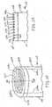
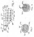
FIG 1 is a side view of an electrosurgical device.FIG 2A is a perspective view of a distal portion of the electrosurgical device.FIG 2B is a cross-sectional view of the distal portion of the device taken along theline 2B-2B' inFIG 2A .FIG 2C is a plan view of the distal portion of the device.FIG 2D is a plan view showing the assembly of a disc included as part of the distal portion of the device.FIG 3 is a schematic diagram showing the connection of electrical energy to the electrosurgical device.FIGS. 4A and4B are simulations of the electric field and current density, respectively, at a surface of the distal portion of the device.FIGS. 4C and4D are simulations showing the electric field for alternate configurations of the distal portion.FIG 5 is a side view showing a use of the electrosurgical device.FIG 6 is a schematic diagram showing a switching network for use with the electrosurgical device.FIGS. 7 and 8 are plan views showing alternate configuration for the distal portion.- Referring to
FIG 1 , anelectrosurgical device 100 includes ahandle 105 connected to anelongated shaft 110 and apower cable 120.Power cable 120 includes apower connector 125 for connection to a source of electrical energy such as an RF power generator (not shown).Shaft 110 is hollow and formed from, e.g., an insulative plastic such as Teflon, polyethylene, polystyrene, or other thermally molded plastic, or made from a metal tube. Shaft 110 has adistal portion 115 that includes aninsulated region 205 terminating at adisc 210.Disc 210 is, e.g., approximately 5 mm in diameter and has an overall thickness of between 0.625 and 1.5 mm (25 and 60 mils).Disc 210 has atissue treatment surface 225 and is formed of a high dielectric material, that is, a material having a dielectric constant greater than about 10, preferably between 100 and 1000.- Referring to
FIGS. 2A-2C , embedded withindisc 210 is anRF antenna 200. TheRF antenna 200 is constructed from a first plurality ofconductive fingers 215a interleaved in a comb-like fashion with a second plurality of conductive fingers 215b such that each one offingers 215a is adjacent to one of fingers 215b.Fingers 215a and 215b are embedded indisc 210 and are shown inFIG 2A as dashed lines. However,FIG 2C illustratesfingers 215a and 215b as solid lines for clarity. Adjacent fingers are equally separated by a distanced, as discussed further below. - The material of
disc 210 preferably also has high electrical isolation to limit voltage breakdown between adjacent conductors. This material is preferably resistant to high temperature and the aggressive chemical environment of RF plasmas. Ceramic is an example of a material that is a high dielectric and has good electrical isolation. Some examples of ceramics suitable for use are those made by American Technical Ceramics, One Norden Lane, Huntington Station, NY 11746 with the dielectric designations of CC, EA, or GA. - As shown in
Fig. 2A ,fingers 215a are connected to afirst lead 220a that connectsfingers 215a to a first terminal of the RF power generator throughpower cable 120 andconnector 125. Similarly, fingers 215b are connected to a second lead 220b that connects conductors 215b to a second terminal of the RF power generator throughpower cable 120 andconnector 125. Accordingly,fingers 215a receive one polarity of the RF voltage, while fingers 215b receive the opposite polarity.Leads 220a and 220b pass through the hollow portion ofshaft 110 topower cable 120. - Referring to
FIG 2D ,disc 210 is, e.g., formed from a first section ofdielectric material 210a and a second section of dielectric material 210b.First section 210a has a thickness of, e.g., between 0.125 to 0.25 mm (5 to 10 mils) and second section 210b has a thickness of, e.g., between 0.5 to 1.25 mm (20 to 50 mils).Sections 210a and 210b can have the same or different dielectric constants. First section 210a hastissue treatment surface 225 and asecond surface 235 opposite fromtissue treatment surface 225. Disposed onsecond surface 235 areconductive fingers 215a and 215b.Fingers 215a and 215b are disposed onsurface 235 using, for example, standard metal deposition and etching techniques.- Second section 210b of dielectric material 210b has a
surface 245 with trenches or voids designed to receiveconductive fingers 215a and 215b such thatfingers 215a and 215b are encapsulated. A bonding technique is used to joinsurfaces fingers 215a and 215b totrenches 240 to form asingle disc 210 withfingers 215a and 215b embedded therein. Second section 210b provides mechanical strength todisc 210 and electrical isolation betweenconductive fingers 215a and 215b. Second section 210b can also act to distribute heat from thesurface 225. - Referring to
FIG 3 ,fingers 215a are connected to afirst terminal 315 of anRF power generator 305 through lead 220a. Similarly, fingers 215b are connected to asecond terminal 310 ofRF power generator 305 through second lead 220b. - When connected to
RF power generator 305,fingers 215a and 215b radiate RF energy as shown by dashedlines 320, which represent the equipotential lines of the electric field, andsolid lines 325, which represent the RF vectors of the electric field. The capacitive impedance ofdisc 210 distributes the RF energy essentially evenly oversurface 225. This electrical impedance is a major component in the RF electrical circuit formed byRF power generator 305, leads 220a and 220b,disc 210 andconductors 215a and 215b. Thus, the surface ofdisc 210 acts as an RF energy distributing component. As a result, the RF energy density is substantially uniformly spread oversurface 225 and is not affected to any significant degree by uneven proximity to the surrounding tissue. - The RF energy is primarily confined to the area in front of
surface 225. Consequently, whensurface 225 is applied to or near the tissue to be treated, the RF energy is applied primarily to the tissue to be treated, which can, e.g., reduce or eliminate collateral damage. - Different delivery rates of RF energy can be used for various treatments. For example, as described further below, a high RF energy density can be used to ignite a plasma discharge for use in ablating or cutting tissue. In a procedure such as coagulation, on the other hand, the RF energy density is kept low enough to prevent the ignition of a plasma discharge. Coagulation is performed using thermal treatment with a RF current density of up to, for example, about 0.8 A/mm squared. Similarly, an electric field with a low power density can be used to kill cells in a treatment area. This is achieved, e.g., by connecting the probe to a low frequency or a pulsing high frequency, voltage source, such as, a high density pulsed electric field, e.g., a pulsing electric field with a duration of about 1 us to 100us, a repetition rate from about 10MHz to 1 Hz, and a voltage field of up to about 200 V/mil (which is equal to 7.9kV/mm).
- Referring to
FIGS. 4A and4B , a simulation, using finite element analysis software, was conducted to demonstrate that the electric field is located primarily at the treatment surface of the dielectric material. For the simulation, copper with an electrical conductivity of 5.8e+07 Siemens per meter was used forfingers 415a and 415b and ceramic with a dielectric constant of 650 was used for highdielectric material 410. The simulation was a two dimensional simulation, with the height of theceramic material 210 being 2.08mm (0.065 inches) and the width being 11.52mm (0.36 inches). The spacing fromsurface 425 toconductors 415a and 415b was 0.16mm (0.005 inches). The thickness ofconductors 415a and 415b was 0.16mm (0.005 inches) and the width ofconductors 415a and 415b was 0.56mm (0.0175 inches). The spacing betweenconductors 415a and 415b was 0.48mm (0.015 inches). The simulation was conducted for a saline environment, using salt water with a dielectric constant of 81 and electrical conductivity of 4 Siemens per meter as the surrounding medium. An RF power source with a voltage magnitude of ± 150 V and a frequency of 13 MHz was applied toconductors 415a and 415b, with conductors 415a receiving one polarity andconductors 415b receiving the opposite polarity. As can be seen,electric field 400 andcurrent density 405 radiated outward fromsurface 425 to a distance of approximately 0.25mm (10 mils) and was confined primarily to the area in front ofsurface 425. - In the simulation, the two end fingers were spaced farther apart from their respective adjacent fingers in an attempt to make the distribution of the electric field and current density more uniform. Because of the boundary conditions at the edges of
material 410, for equally spacedfingers 415a and 415b, the distribution of the electric field and current density will be different at the edges of the material than in the central portion. By adjusting the spacing between the fingers at each edge, a more uniform distribution of the RF current and electric field acrosssurface 425 can be achieved. - Unequal spacing can also be used between adjacent conductors so that the RF electric field radiates or extends outward to different distances in different areas of
surface 425 or, in other words, an RF field is produced that has different penetration depths in different areas ofsurface 425. As described, when RF power is applied tofingers 415a and 415b, a high concentration of the RF electric field is created atsurface 425. The thickness of this field is a function of the distance d between adjacent fingers of opposite polarity. The further apart conductors of opposite polarity are, the further the electric field extends fromsurface 425. Thus, the spacing of the conductors can be optimized for specific applications. - Referring to
FIG 4C , a simulation was conducted demonstrating that different penetration depths of the electric field can be achieved with different spacings between adjacent fingers. The width and thickness of the conductors was 0.1875mm (7.5 mils) and 0.125mm (5 mils), respectively. Afirst set 430a offingers 415a and 415b are spaced 0.1875mm (7.5 mils) apart, while a second set 430b offingers 415a and 415b are spaced 0.75mm (30 mils apart). The other parameters are the same as those forFIGS. 4A and4B . As can be seen, theelectric field 435 has a first area 440a above thefirst set 430a offingers 415a and 415b that extends out from surface 425 a smaller distance than a second area 440b of theelectric field 435 above the second set 430b offingers 415a and 415b. The first area 440a extends approximately 0.25mm (10 mils), while the second area 440b extends approximately 1mm (40 mils). - Referring to
FIG 4D , another simulation was performed to demonstrate that the shape offingers 415a and 415b affects the penetration depth in addition to the spacing betweenfingers 415a and 415b. The parameters are the same as those forFIG 4C , except that the width and thickness of the second set 430b offingers 415a and 415b are 0.4375mm (17.5 mils) and 0.125mm (5 mils), respectively. As shown, increasing the width of the second set of fingers 430b resulted in the second area 440b of theelectric field 435 extending further fromsurface 425 than first area 440a. - A dielectric barrier discharge (DBD) plasma can be ignited at
surface 225 when RF energy is applied toconductors 215a and 215b. This discharge is particularly applicable when the goal is to cut or ablate tissue. The plasma exists primarily in a thin layer oversurface 225. As a result, collateral damage due to the plasma is reduced or eliminated. - The current density needed to ignite the discharge plasma is obtained by adjusting the voltage or frequency of the RF power applied for a given thickness and dielectric constant of
disc 210. For example, assuming a current density of 0.2 A/mm2 is needed to ignite a discharge, then a voltage and frequency of the RF power applied toconductors 215a and 215b equal to 570 V and 5 MHz, respectively, can be used for a thickness ofdisc 210 equal to 0.125 mm and a dielectric constant ofdisc 210 equal to 200. - To arrive at this, the following relationship is used:

- The capacitance in picofarads is equal to:

material 210 andd is the thickness ofmaterial 210 in millimeters, and A is surface area ofmaterial 210 in millimeters squared. Thus, the RF voltageVRF becomes:

- Choosing a frequencyf = 5MHz results in a voltageVRf=570V. The frequency or voltage is preferably chosen in view of other parameters such as the dielectric breakdown of
disc 210. For example, ifdisc 210 has a dielectric strength of 150 V/mils, then for a thickness of 0.125mm (5 mils) the dielectric material has a breakdown voltage of 750 V. Accordingly, the above parameters could be used without exceeded the breakdown voltage ofdisc 210. - The particular parameters required to ignite the plasma in a given environment can be determined as a matter of routine experimentation. The frequency of the RF energy can be up to approximately 20 MHz. Theoretically, frequencies higher than 20 MHz can be used, but in practice such high frequencies are difficult to generate and can cause problems such as interference with other electrical devices. Generally, plasma ignition in saline is achieved with approximately a quarter of the RF field strength required for ignition in air.
- Referring to
FIG. 5 , in use to treatbody tissue 505, such as, for example, articular cartilage,surface 225 is placed in contact with atissue treatment site 510 or near enough to thetissue treatment site 510 that the electric field or plasma discharge region affects thetreatment site 510. As a surgeon applies energy tofingers 215a and 215b, RF energy is radiated outward and distributed alongsurface 225, in a pattern similar to that shown inFIGS. 4A and4B . In a treatment including, for example, ablation of tissue attissue treatment site 510, the RF power applied toconductors 215a and 215b is such that aDBD plasma 515 is formed atsurface 225. To ablate an area of tissue,distal portion 115 along withplasma 515 is moved along the desired ablation area of tissue. - Other surgical procedures (e.g., coagulation or treatment of skin lesions) are performed without forming a DBD plasma. Rather, the RF electric field distributed across and extending from
surface 225, and/or any thermal energy resulting from the electric field, is used to treat the tissue. The heat is dissipated in the treated tissue limiting any collateral damage to the surrounding tissue. - Thus, during use, RF energy is applied to a target tissue with a conductor such that the RF energy is applied without galvanic contact (i.e., without direct electric contact) between the conductor and the target tissue or between the conductor and a conductive medium surrounding the target tissue. In the implementations shown, the RF energy is applied through the dielectric material without the conductors and being in direct electric contact with the tissue and without the conductors being in direct electrical contact with a conductive medium (e.g., saline) surrounding the tissue.
- Referring to
FIG. 6 , for some electrosurgical procedures it is desirable to have the ability to adjust the penetration depth of the RF field. As described above, different spacings between adjacent fingers provide for different penetration depths of the RF field. Aswitching network 650 is one example of how to adjust the RF electric field's depth of penetration.RF generator 605, disc 610, andfingers 651a and 615b are the same as described inFIGS. 1-3 andfingers Fingers RF generator 605 through switchingnetwork 650 and threeleads Switching network 650 has two switches,switch 630 andswitch 635. When first andsecond switches fingers 615a are connected tofirst terminal 640 of RF generator through bothleads 620a and 620b, while all offingers 615b are connected tosecond terminal 645 throughlead 620c. In this configuration, the distance between adjacent conductors of opposite polarity isd1 and an electric field extends a first length fromsurface 625 of high dielectric material 610. - When first and
second switches fingers 615a are connected tosecond terminal 645 ofRF generator 605 through lead 620b, while theother fingers 615a are connected tofirst terminal 640.Conductors 615b are not connected to either terminal ofRF generator 605. In this configuration, the distance between adjacent conductors of opposite polarity isd2, which is greater than distance d1. As a result, the electric field extends a second length fromsurface 625, which is farther than the first length. - A number of implementations have been described. Nevertheless, it will be understood that various modifications may be made. For example, other configurations of
electrosurgical device 100 have the insulating material ofportion 205 covering the side 230 (FIG 2A ) ofsection 210, while leavingsurface 225 exposed. Also,shaft 110 can be made from other materials and with different configurations. For instance,distal portion 115 can have a ninety degree bend such thatsurface 225 is side-facing. Other bend degrees are also possible such as, for example, sixty degrees, forty-five degrees, or thirty degrees, or the shaft can be flexible with an adjustable angle. - Other dimensions and shapes of
disc 210 can be used, depending on the application and the surface area of treatment. Also, while it may be desirable to use a material fordisc 210 with high electrical isolation, the material can have some conductivity For example, a semiconductor material can be used. - Other configurations of
disc 210 can also be used. For example,disc 210 has varying dielectric constants along a length and/or diameter. Referring toFIG 7 , for example, conductors 715a and 715b are embedded indisc 710.Disc 710 has three distinct sections, 720, 725, and 730. Eachsection - Further, the second section of dielectric material 210b can be eliminated and other techniques used to insure electrical isolation between
conductive fingers 215a and 215b. For example, a coating of glass or other insulating material is applied tosurface 235 andconductors 215a and 215b to provide electrical isolation betweenconductors 215a and 215b. Alternatively,distal portion 115 is configured such that a vacuum exists at thesurface 235 of dielectric 210a to provide electrical isolation betweenconductors 215a and 215b. - Other configurations of the embedded conductors can also be used. Referring to
FIG 8 , for example, conductors 715a and 715b are interleaved as concentric circles. Fingers 715a are connected to one terminal of the RF power generator, while fingers 715b are connected to the other terminal. - Moreover,
electrosurgical device 100 can have other configurations. For example,electrosurgical device 100 is provided with an internal RF generator, andpower cable 120 andconnector 125 connect the internal RF generator to AC or DC power. Alternatively, in addition to an internal RF generator, electrosurgical device includes an internal battery to power the RF generator. In this case,power cable 120 andconnector 125 are eliminated. The electrosurgical device can be implemented as a self-coagulating surgical blade. When implemented in this manner, dielectric material 210b is deposited at the surface of a surgical blade for instant coagulation of, e.g., small arteries. - While an electrosurgical device has been described as dimensioned for endoscopic or arthroscopic surgeries, other implementations are dimensioned larger or smaller, depending on the particular application intended. In such applications, the thickness and size of the
high dielectric material 210a is adjusted accordingly - Accordingly, other implementations are within the scope of the following claims.


Claims (25)
- An electrosurgical device (100) comprising: a high dielectric material (210, 410, 610, 710, 810) having a dielectric constant of at least 10; and means for delivering energy to a target tissue through the high dielectric material;characterised in that the means comprises first and second conductors (215a, 215b, 415a, 415b, 615a, 615b, 715a, 715b, 815a, 815b); andin that the first and second conductors are embedded in the high dielectric material (210, 410, 610, 710, 810) such that, in use, the high dielectric material is disposed between the conductors (215a, 215b, 415a, 415b, 615a, 615b, 715a, 715b, 815a, 815b) and target tissue.
- An electrosurgical device (100) according to claim 1 wherein the dielectric constant is between 100 and 1000.
- An electrosurgical device (100) according to claims 1 to 2 wherein the high dielectric material (210) comprises a ceramic material.
- An electrosurgical device (100) according to claims 1 to 3 wherein the high dielectric material (210) comprises a material having high electrical isolation.
- An electrosurgical device (100) according to claims 1 to 4 wherein; the first conductor (215a, 415a, 615a, 715a) comprises a first plurality of conductive fingers; the second conductor (215b, 415b, 615b, 715b) comprises a second plurality of conductive fingers; and wherein the first plurality of fingers is interleaved with the second plurality of fingers.
- An electrosurgical device (100) according to claim 5 wherein the high dielectric material (210) comprises first and second sections (210a, 210b), and the first and second conductors (215a, 215b) are embedded between the first and second sections (210a, 210b).
- An electrosurgical device (100) according to claim 5 or 6 wherein the first plurality of fingers and the second plurality of fingers are interleaved in a comb-like fashion.
- An electrosurgical device (100) according to claims 1 to 4 wherein the first and second conductors (815a, 815b) each comprise a set of concentric circles, the concentric circles being interleaved.
- An electrosurgical device (100) according to any preceding claim further comprising an RF generator (305, 605) connected to at least one conductor (315a, 315b, 615a, 615b).
- An electrosurgical device (100) according to claim 9 wherein the RF generator (305, 605) is configured to provide RF power with a voltage and a frequency sufficient to result in a dielectric discharge barrier plasma being formed at a surface of the high dielectric material (310, 610).
- An electrosurgical device (100) according to claims 9 or 10 wherein the RF generator (305, 605) is configured to provide RF power at a frequency up to about 20 MHz.
- An electrosurgical device (100) according to claims 9 to 11 wherein the RF generator (305, 605) is configured to provide RF power at a voltage up to about 1500 Vrms.
- An electrosurgical device (100) according to claims 9 to 12 wherein the RF generator (305, 605) is configured to provide RF power with a voltage and a frequency sufficient to result in a RF field with a current density at a surface of the high dielectric material that is greater than about 0.2amps/mm2.
- An electrosurgical device (100) according to claims 9 to 13 wherein the RF generator (305, 605) is configured to provide RF power with a voltage and a frequency sufficient to result in a RF field with a current density at a surface of the high dielectric material (310, 610) that is up to about 1.0 amps/mm2.
- An electrosurgical device (100) according to claims 9 to 14 wherein the RF generator (305, 605) is configured to provide RF power sufficient to result in high density RF currents being formed at a surface of the high dielectric material (310, 610).
- An electrosurgical device (100) according to claims 9 to 15 wherein the RF generator (305, 605) is configured to provide RF power sufficient to result in a high strength RF electrical field being formed at the surface of the high dielectric material (310, 610).
- An electrosurgical device (100) according to claims 5 to 7 further comprising: an RF generator (605) connected to at least one conductor (615a, 615b); and a switching network (650) coupling the first and second plurality of fingers to the RF power generator.
- An electrosurgical device (100) according to claim 17 wherein the switching network (650) has a first state in which the RF electrical field extends to a first distance from a tissue treatment surface of the high dielectric material (610) and a second state in which the RF electrical field extends to a second distance from the tissue treatment surface, wherein the second distance is longer than the first distance.
- An electrosurgical device (100) according to claims 17 or 18 wherein the RF generator (605) is configured to provide RF power with a voltage and a frequency sufficient to result in a dielectric discharge barrier plasma being formed at the surface of the high dielectric material (610).
- An electrosurgical device (100) according to claims 17 to 19 wherein the RF generator (605) is configured to provide RF power at a frequency up to about 20 MHz.
- An electrosurgical device (100) according to claims 17 to 20 wherein the RF generator (605) is configured to provide RF power at a voltage up to about 1500 Vrms.
- An electrosurgical device (100) according to claims 17 to 21 wherein the RF generator (605) is configured to provide a RF power with a voltage and a frequency sufficient to result in a RF field with a current density at a surface of the high dielectric material (610) that is greater than about 0.2amps/mm2.
- An electrosurgical device (100) according to claims 17 to 22 wherein the RF generator (605) is configured to provide RF power with a voltage and a frequency sufficient to result in a RF field with current density at a surface of the high dielectric material (610) that is up to about 1.0amps/mm2.
- An electrosurgical device (100) according to claims 17 to 23 wherein the RF generator (605) is configured to provide RF power sufficient to result in a high density RF currents being formed at a surface of the high dielectric material (610).
- An electrosurgical device (100) according to claims 17 to 24 wherein the RF generator (605) is configured to provide RF power sufficient to result in a high strength RF electrical field being formed at a surface of the high dielectric material (610).
Applications Claiming Priority (2)
| Application Number | Priority Date | Filing Date | Title |
|---|---|---|---|
| US10/747,101US7182762B2 (en) | 2003-12-30 | 2003-12-30 | Electrosurgical device |
| PCT/US2004/043110WO2005065560A1 (en) | 2003-12-30 | 2004-12-21 | Electrosurgical device |
Publications (2)
| Publication Number | Publication Date |
|---|---|
| EP1699374A1 EP1699374A1 (en) | 2006-09-13 |
| EP1699374B1true EP1699374B1 (en) | 2013-04-10 |
Family
ID=34700691
Family Applications (1)
| Application Number | Title | Priority Date | Filing Date |
|---|---|---|---|
| EP04815222.7AExpired - LifetimeEP1699374B1 (en) | 2003-12-30 | 2004-12-21 | Electrosurgical device |
Country Status (5)
| Country | Link |
|---|---|
| US (2) | US7182762B2 (en) |
| EP (1) | EP1699374B1 (en) |
| JP (1) | JP4707676B2 (en) |
| AU (1) | AU2004312037B2 (en) |
| WO (1) | WO2005065560A1 (en) |
Families Citing this family (83)
| Publication number | Priority date | Publication date | Assignee | Title |
|---|---|---|---|---|
| US6780178B2 (en) | 2002-05-03 | 2004-08-24 | The Board Of Trustees Of The Leland Stanford Junior University | Method and apparatus for plasma-mediated thermo-electrical ablation |
| US8043286B2 (en) | 2002-05-03 | 2011-10-25 | The Board Of Trustees Of The Leland Stanford Junior University | Method and apparatus for plasma-mediated thermo-electrical ablation |
| EP1603474B1 (en)* | 2003-02-14 | 2013-09-11 | The Board Of Trustees Of The Leland Stanford Junior University | Electrosurgical system with uniformly enhanced electric field and minimal collateral damage |
| US7736361B2 (en) | 2003-02-14 | 2010-06-15 | The Board Of Trustees Of The Leland Stamford Junior University | Electrosurgical system with uniformly enhanced electric field and minimal collateral damage |
| EP1648280A4 (en)* | 2003-06-18 | 2007-08-15 | Univ Leland Stanford Junior | ELECTRO-ADHESIVE TISSUE MANIPULATOR |
| US8182501B2 (en) | 2004-02-27 | 2012-05-22 | Ethicon Endo-Surgery, Inc. | Ultrasonic surgical shears and method for sealing a blood vessel using same |
| US20070016181A1 (en) | 2004-04-29 | 2007-01-18 | Van Der Weide Daniel W | Microwave tissue resection tool |
| US20070055224A1 (en)* | 2004-04-29 | 2007-03-08 | Lee Fred T Jr | Intralumenal microwave device |
| US20060079879A1 (en) | 2004-10-08 | 2006-04-13 | Faller Craig N | Actuation mechanism for use with an ultrasonic surgical instrument |
| EP1715810B1 (en)* | 2005-01-18 | 2012-05-09 | Alma Lasers Ltd | Improved system for heating biological tissue via rf energy |
| US9215788B2 (en)* | 2005-01-18 | 2015-12-15 | Alma Lasers Ltd. | System and method for treating biological tissue with a plasma gas discharge |
| US7655003B2 (en) | 2005-06-22 | 2010-02-02 | Smith & Nephew, Inc. | Electrosurgical power control |
| US20070191713A1 (en) | 2005-10-14 | 2007-08-16 | Eichmann Stephen E | Ultrasonic device for cutting and coagulating |
| US8246642B2 (en)* | 2005-12-01 | 2012-08-21 | Ethicon Endo-Surgery, Inc. | Ultrasonic medical instrument and medical instrument connection assembly |
| JP5032500B2 (en)* | 2006-01-03 | 2012-09-26 | アルコン,インコーポレイティド | System for dissociation and removal of proteinaceous tissue |
| US20070167965A1 (en)* | 2006-01-05 | 2007-07-19 | Ethicon Endo-Surgery, Inc. | Ultrasonic medical instrument |
| US7621930B2 (en)* | 2006-01-20 | 2009-11-24 | Ethicon Endo-Surgery, Inc. | Ultrasound medical instrument having a medical ultrasonic blade |
| US20070173872A1 (en)* | 2006-01-23 | 2007-07-26 | Ethicon Endo-Surgery, Inc. | Surgical instrument for cutting and coagulating patient tissue |
| US20070191712A1 (en)* | 2006-02-15 | 2007-08-16 | Ethicon Endo-Surgery, Inc. | Method for sealing a blood vessel, a medical system and a medical instrument |
| US7854735B2 (en)* | 2006-02-16 | 2010-12-21 | Ethicon Endo-Surgery, Inc. | Energy-based medical treatment system and method |
| US8672932B2 (en)* | 2006-03-24 | 2014-03-18 | Neuwave Medical, Inc. | Center fed dipole for use with tissue ablation systems, devices and methods |
| US10363092B2 (en) | 2006-03-24 | 2019-07-30 | Neuwave Medical, Inc. | Transmission line with heat transfer ability |
| US10376314B2 (en) | 2006-07-14 | 2019-08-13 | Neuwave Medical, Inc. | Energy delivery systems and uses thereof |
| US11389235B2 (en) | 2006-07-14 | 2022-07-19 | Neuwave Medical, Inc. | Energy delivery systems and uses thereof |
| GB0620061D0 (en)* | 2006-10-10 | 2006-11-22 | Medical Device Innovations Ltd | Oesophageal treatment apparatus and method |
| US20080103529A1 (en)* | 2006-10-26 | 2008-05-01 | Old Dominion University | Apparatus and methods for performing cellular electro-manipulations |
| JP2010508899A (en) | 2006-11-02 | 2010-03-25 | ピーク サージカル, インコーポレイテッド | Tissue cutting and coagulation with electrical plasma, and surgical devices |
| US8784425B2 (en) | 2007-02-28 | 2014-07-22 | Smith & Nephew, Inc. | Systems and methods for identifying landmarks on orthopedic implants |
| EP2114263B1 (en)* | 2007-02-28 | 2019-02-20 | Smith & Nephew, Inc. | System for identifying a landmark |
| US8814868B2 (en)* | 2007-02-28 | 2014-08-26 | Smith & Nephew, Inc. | Instrumented orthopaedic implant for identifying a landmark |
| US8911460B2 (en) | 2007-03-22 | 2014-12-16 | Ethicon Endo-Surgery, Inc. | Ultrasonic surgical instruments |
| US8057498B2 (en) | 2007-11-30 | 2011-11-15 | Ethicon Endo-Surgery, Inc. | Ultrasonic surgical instrument blades |
| US8523889B2 (en) | 2007-07-27 | 2013-09-03 | Ethicon Endo-Surgery, Inc. | Ultrasonic end effectors with increased active length |
| US8808319B2 (en) | 2007-07-27 | 2014-08-19 | Ethicon Endo-Surgery, Inc. | Surgical instruments |
| US8430898B2 (en) | 2007-07-31 | 2013-04-30 | Ethicon Endo-Surgery, Inc. | Ultrasonic surgical instruments |
| US9044261B2 (en) | 2007-07-31 | 2015-06-02 | Ethicon Endo-Surgery, Inc. | Temperature controlled ultrasonic surgical instruments |
| US8512365B2 (en) | 2007-07-31 | 2013-08-20 | Ethicon Endo-Surgery, Inc. | Surgical instruments |
| US20090082762A1 (en)* | 2007-09-20 | 2009-03-26 | Ormsby Theodore C | Radio frequency energy transmission device for the ablation of biological tissues |
| US10010339B2 (en) | 2007-11-30 | 2018-07-03 | Ethicon Llc | Ultrasonic surgical blades |
| US9220514B2 (en)* | 2008-02-28 | 2015-12-29 | Smith & Nephew, Inc. | System and method for identifying a landmark |
| US20090306642A1 (en)* | 2008-06-10 | 2009-12-10 | Vankov Alexander B | Method for low temperature electrosugery and rf generator |
| CN102112178B (en)* | 2008-08-04 | 2014-04-23 | 剑威医疗株式会社 | DC dielectric barrier discharge electron irradiation apparatus and electrotherapy device |
| US8388615B2 (en)* | 2008-10-28 | 2013-03-05 | Smith & Nephew, Inc. | Electrosurgical device with controllable electric field profile |
| US8137345B2 (en) | 2009-01-05 | 2012-03-20 | Peak Surgical, Inc. | Electrosurgical devices for tonsillectomy and adenoidectomy |
| US9031637B2 (en) | 2009-04-27 | 2015-05-12 | Smith & Nephew, Inc. | Targeting an orthopaedic implant landmark |
| US8945147B2 (en) | 2009-04-27 | 2015-02-03 | Smith & Nephew, Inc. | System and method for identifying a landmark |
| US8650728B2 (en) | 2009-06-24 | 2014-02-18 | Ethicon Endo-Surgery, Inc. | Method of assembling a transducer for a surgical instrument |
| EP3549544B1 (en) | 2009-07-28 | 2021-01-06 | Neuwave Medical, Inc. | DEVICE FOR ABLATION |
| US8086734B2 (en) | 2009-08-26 | 2011-12-27 | International Business Machines Corporation | Method of autonomic representative selection in local area networks |
| US20110118729A1 (en)* | 2009-11-13 | 2011-05-19 | Alcon Research, Ltd | High-intensity pulsed electric field vitrectomy apparatus with load detection |
| US20110118734A1 (en)* | 2009-11-16 | 2011-05-19 | Alcon Research, Ltd. | Capsularhexis device using pulsed electric fields |
| US20110135626A1 (en)* | 2009-12-08 | 2011-06-09 | Alcon Research, Ltd. | Localized Chemical Lysis of Ocular Tissue |
| US20110144562A1 (en)* | 2009-12-14 | 2011-06-16 | Alcon Research, Ltd. | Localized Pharmacological Treatment of Ocular Tissue Using High-Intensity Pulsed Electrical Fields |
| WO2011081897A1 (en)* | 2009-12-15 | 2011-07-07 | Alcon Research, Ltd. | High-intensity pulsed electric field vitrectomy apparatus |
| US8486096B2 (en) | 2010-02-11 | 2013-07-16 | Ethicon Endo-Surgery, Inc. | Dual purpose surgical instrument for cutting and coagulating tissue |
| US8951272B2 (en) | 2010-02-11 | 2015-02-10 | Ethicon Endo-Surgery, Inc. | Seal arrangements for ultrasonically powered surgical instruments |
| WO2011113148A1 (en) | 2010-03-15 | 2011-09-22 | 4463251 Canada Inc. | Method and apparatus for regenerating vulcanized rubber |
| ES2856026T3 (en) | 2010-05-03 | 2021-09-27 | Neuwave Medical Inc | Power supply systems |
| RU2012157125A (en) | 2010-06-03 | 2014-07-20 | Смит Энд Нефью, Инк. | ORTHOPEDIC IMPLANT |
| US8546979B2 (en) | 2010-08-11 | 2013-10-01 | Alcon Research, Ltd. | Self-matching pulse generator with adjustable pulse width and pulse frequency |
| US10335223B2 (en) | 2010-10-26 | 2019-07-02 | Erbe Elektromedizin Gmbh | Hemostasis instrument |
| WO2012103169A2 (en) | 2011-01-25 | 2012-08-02 | Smith & Nephew, Inc. | Targeting operation sites |
| RU2013153116A (en) | 2011-05-06 | 2015-06-20 | Смит Энд Нефью, Инк. | TARGETING FOR SIGNIFICANT POINTS OF ORTHOPEDIC DEVICES |
| WO2012170364A1 (en) | 2011-06-10 | 2012-12-13 | Medtronic, Inc. | Wire electrode devices for tonsillectomy and adenoidectomy |
| WO2012173890A2 (en) | 2011-06-16 | 2012-12-20 | Smith & Nephew, Inc. | Surgical alignment using references |
| US9192438B2 (en) | 2011-12-21 | 2015-11-24 | Neuwave Medical, Inc. | Energy delivery systems and uses thereof |
| US9820768B2 (en) | 2012-06-29 | 2017-11-21 | Ethicon Llc | Ultrasonic surgical instruments with control mechanisms |
| US10226273B2 (en) | 2013-03-14 | 2019-03-12 | Ethicon Llc | Mechanical fasteners for use with surgical energy devices |
| US8992525B2 (en)* | 2013-07-31 | 2015-03-31 | Ent Biotech Solutions, Inc. | Surgical instrument |
| GB2521229A (en) | 2013-12-16 | 2015-06-17 | Ethicon Endo Surgery Inc | Medical device |
| US11020140B2 (en) | 2015-06-17 | 2021-06-01 | Cilag Gmbh International | Ultrasonic surgical blade for use with ultrasonic surgical instruments |
| US10357303B2 (en) | 2015-06-30 | 2019-07-23 | Ethicon Llc | Translatable outer tube for sealing using shielded lap chole dissector |
| US11446078B2 (en) | 2015-07-20 | 2022-09-20 | Megadyne Medical Products, Inc. | Electrosurgical wave generator |
| CN113367788B (en) | 2015-10-26 | 2024-09-06 | 纽韦弗医疗设备公司 | Energy delivery systems and uses thereof |
| US10531917B2 (en) | 2016-04-15 | 2020-01-14 | Neuwave Medical, Inc. | Systems and methods for energy delivery |
| US10245064B2 (en) | 2016-07-12 | 2019-04-02 | Ethicon Llc | Ultrasonic surgical instrument with piezoelectric central lumen transducer |
| USD847990S1 (en) | 2016-08-16 | 2019-05-07 | Ethicon Llc | Surgical instrument |
| US10736649B2 (en) | 2016-08-25 | 2020-08-11 | Ethicon Llc | Electrical and thermal connections for ultrasonic transducer |
| US10952759B2 (en) | 2016-08-25 | 2021-03-23 | Ethicon Llc | Tissue loading of a surgical instrument |
| KR101813558B1 (en)* | 2017-04-12 | 2018-01-03 | 주식회사 서린메디케어 | Skin treatment apparatus using fractional plasma |
| US11672596B2 (en) | 2018-02-26 | 2023-06-13 | Neuwave Medical, Inc. | Energy delivery devices with flexible and adjustable tips |
| US11832879B2 (en) | 2019-03-08 | 2023-12-05 | Neuwave Medical, Inc. | Systems and methods for energy delivery |
| US20240196507A1 (en)* | 2022-06-26 | 2024-06-13 | TellaPure, LLC | Methods and apparatus for generating atmospheric pressure, low temperature plasma usable for affecting fluid flow |
Family Cites Families (43)
| Publication number | Priority date | Publication date | Assignee | Title |
|---|---|---|---|---|
| US164184A (en) | 1875-06-08 | Improvement in vesicular electrodes | ||
| US3460539A (en) | 1967-03-10 | 1969-08-12 | James E Anhalt Sr | Cautery tip |
| DE2324658B2 (en) | 1973-05-16 | 1977-06-30 | Richard Wolf Gmbh, 7134 Knittlingen | PROBE FOR COAGULATING BODY TISSUE |
| US4033351A (en) | 1974-06-14 | 1977-07-05 | Siemens Aktiengesellschaft | Bipolar cutting electrode for high-frequency surgery |
| US4232676A (en)* | 1978-11-16 | 1980-11-11 | Corning Glass Works | Surgical cutting instrument |
| US4654024A (en) | 1985-09-04 | 1987-03-31 | C.R. Bard, Inc. | Thermorecanalization catheter and method for use |
| US4765331A (en) | 1987-02-10 | 1988-08-23 | Circon Corporation | Electrosurgical device with treatment arc of less than 360 degrees |
| US4799480A (en) | 1987-08-04 | 1989-01-24 | Conmed | Electrode for electrosurgical apparatus |
| US4832048A (en) | 1987-10-29 | 1989-05-23 | Cordis Corporation | Suction ablation catheter |
| WO1989011311A1 (en) | 1988-05-18 | 1989-11-30 | Kasevich Associates, Inc. | Microwave balloon angioplasty |
| AU4945490A (en) | 1989-01-06 | 1990-08-01 | Angioplasty Systems Inc. | Electrosurgical catheter for resolving atherosclerotic plaque |
| US5383917A (en) | 1991-07-05 | 1995-01-24 | Jawahar M. Desai | Device and method for multi-phase radio-frequency ablation |
| US5697281A (en) | 1991-10-09 | 1997-12-16 | Arthrocare Corporation | System and method for electrosurgical cutting and ablation |
| US5697909A (en) | 1992-01-07 | 1997-12-16 | Arthrocare Corporation | Methods and apparatus for surgical cutting |
| US5419767A (en) | 1992-01-07 | 1995-05-30 | Thapliyal And Eggers Partners | Methods and apparatus for advancing catheters through severely occluded body lumens |
| US5902272A (en)* | 1992-01-07 | 1999-05-11 | Arthrocare Corporation | Planar ablation probe and method for electrosurgical cutting and ablation |
| US5681282A (en) | 1992-01-07 | 1997-10-28 | Arthrocare Corporation | Methods and apparatus for ablation of luminal tissues |
| US5683366A (en) | 1992-01-07 | 1997-11-04 | Arthrocare Corporation | System and method for electrosurgical tissue canalization |
| US5697882A (en) | 1992-01-07 | 1997-12-16 | Arthrocare Corporation | System and method for electrosurgical cutting and ablation |
| US5891095A (en) | 1993-05-10 | 1999-04-06 | Arthrocare Corporation | Electrosurgical treatment of tissue in electrically conductive fluid |
| US5562720A (en) | 1992-05-01 | 1996-10-08 | Vesta Medical, Inc. | Bipolar/monopolar endometrial ablation device and method |
| DE4229085C2 (en)* | 1992-09-01 | 1996-07-11 | Boehringer Mannheim Gmbh | Elongated, divisible tablet |
| US5380320A (en)* | 1993-11-08 | 1995-01-10 | Advanced Surgical Materials, Inc. | Electrosurgical instrument having a parylene coating |
| US5462521A (en) | 1993-12-21 | 1995-10-31 | Angeion Corporation | Fluid cooled and perfused tip for a catheter |
| AU3684595A (en) | 1994-09-30 | 1996-04-26 | Regents Of The University Of California, The | Systems and methods for ablating body tissue |
| US6264650B1 (en) | 1995-06-07 | 2001-07-24 | Arthrocare Corporation | Methods for electrosurgical treatment of intervertebral discs |
| US5769879A (en)* | 1995-06-07 | 1998-06-23 | Medical Contouring Corporation | Microwave applicator and method of operation |
| US5697925A (en) | 1995-06-09 | 1997-12-16 | Engineering & Research Associates, Inc. | Apparatus and method for thermal ablation |
| US7186234B2 (en)* | 1995-11-22 | 2007-03-06 | Arthrocare Corporation | Electrosurgical apparatus and methods for treatment and removal of tissue |
| US6413255B1 (en)* | 1999-03-09 | 2002-07-02 | Thermage, Inc. | Apparatus and method for treatment of tissue |
| US7452358B2 (en) | 1996-01-05 | 2008-11-18 | Thermage, Inc. | RF electrode assembly for handpiece |
| US7189230B2 (en) | 1996-01-05 | 2007-03-13 | Thermage, Inc. | Method for treating skin and underlying tissue |
| US7267675B2 (en)* | 1996-01-05 | 2007-09-11 | Thermage, Inc. | RF device with thermo-electric cooler |
| US6068628A (en) | 1996-08-20 | 2000-05-30 | Oratec Interventions, Inc. | Apparatus for treating chondromalacia |
| US6091995A (en)* | 1996-11-08 | 2000-07-18 | Surx, Inc. | Devices, methods, and systems for shrinking tissues |
| DE69828988T2 (en)* | 1997-10-03 | 2006-04-13 | Megadyne Medical Products, Inc., Draper | ELECTROCOSPHERIC ELECTRODE CONCENTRATING AN ELECTRIC FIELD |
| EP1063931A2 (en)* | 1998-03-19 | 2001-01-03 | Oratec Interventions, Inc. | Catheter for delivery of energy to a surgical site |
| GB9813042D0 (en)* | 1998-06-17 | 1998-08-12 | Nuvotek Ltd | Electrosurgical cutting tool |
| US6190382B1 (en) | 1998-12-14 | 2001-02-20 | Medwaves, Inc. | Radio-frequency based catheter system for ablation of body tissues |
| US6070444A (en)* | 1999-03-31 | 2000-06-06 | Sherwood Services Ag | Method of mass manufacturing coated electrosurgical electrodes |
| US6692489B1 (en) | 1999-07-21 | 2004-02-17 | Team Medical, Llc | Electrosurgical mode conversion system |
| US6758846B2 (en)* | 2000-02-08 | 2004-07-06 | Gyrus Medical Limited | Electrosurgical instrument and an electrosurgery system including such an instrument |
| US7879034B2 (en)* | 2006-03-02 | 2011-02-01 | Arthrocare Corporation | Internally located return electrode electrosurgical apparatus, system and method |
- 2003
- 2003-12-30USUS10/747,101patent/US7182762B2/ennot_activeExpired - Fee Related
- 2004
- 2004-12-21AUAU2004312037Apatent/AU2004312037B2/ennot_activeCeased
- 2004-12-21JPJP2006547304Apatent/JP4707676B2/ennot_activeExpired - Fee Related
- 2004-12-21EPEP04815222.7Apatent/EP1699374B1/ennot_activeExpired - Lifetime
- 2004-12-21WOPCT/US2004/043110patent/WO2005065560A1/ennot_activeApplication Discontinuation
- 2007
- 2007-02-23USUS11/678,308patent/US20070219406A1/ennot_activeAbandoned
Also Published As
| Publication number | Publication date |
|---|---|
| AU2004312037A1 (en) | 2005-07-21 |
| JP4707676B2 (en) | 2011-06-22 |
| EP1699374A1 (en) | 2006-09-13 |
| US7182762B2 (en) | 2007-02-27 |
| US20050143726A1 (en) | 2005-06-30 |
| JP2007516788A (en) | 2007-06-28 |
| US20070219406A1 (en) | 2007-09-20 |
| WO2005065560A1 (en) | 2005-07-21 |
| AU2004312037B2 (en) | 2011-09-01 |
Similar Documents
| Publication | Publication Date | Title |
|---|---|---|
| EP1699374B1 (en) | Electrosurgical device | |
| EP3363396B1 (en) | Apparatus for electrosurgery comprising superposed electrodes with curved distal parts | |
| EP0051640B1 (en) | A multipolar electrosurgical device | |
| EP1996105B1 (en) | Internally located return electrode electrosurgical apparatus | |
| US9168082B2 (en) | Fine dissection electrosurgical device | |
| US6786906B1 (en) | Electrosurgical cutting tool | |
| US8500729B2 (en) | Electrosurgical device with controllable electric field profile | |
| US9271784B2 (en) | Fine dissection electrosurgical device | |
| EP2046221A2 (en) | Bipolar electrosurgical scissors | |
| WO2007059769A1 (en) | Method and apparatus for substantial and uniform ablation about a linear bipolar array of electrodes | |
| EP1439793A4 (en) | Self-wetting, dry-field bipolar electrodes for endoscopic surgery | |
| WO1998031290A9 (en) | Bipolar vaporization apparatus and method for arthroscopy | |
| EP3975894A1 (en) | Electrosurgical electrode and electrosurgical tool for conveying electrical energy | |
| GB2514231A (en) | Fine dissection electrosurgical device | |
| US11291501B2 (en) | Radio frequency ablation systems | |
| JP5156893B2 (en) | High-frequency treatment device, high-frequency treatment system, and methods of use thereof | |
| JP2008245990A5 (en) |
Legal Events
| Date | Code | Title | Description |
|---|---|---|---|
| PUAI | Public reference made under article 153(3) epc to a published international application that has entered the european phase | Free format text:ORIGINAL CODE: 0009012 | |
| 17P | Request for examination filed | Effective date:20060601 | |
| AK | Designated contracting states | Kind code of ref document:A1 Designated state(s):AT BE BG CH CY CZ DE DK EE ES FI FR GB GR HU IE IS IT LI LT LU MC NL PL PT RO SE SI SK TR | |
| DAX | Request for extension of the european patent (deleted) | ||
| 17Q | First examination report despatched | Effective date:20080902 | |
| GRAP | Despatch of communication of intention to grant a patent | Free format text:ORIGINAL CODE: EPIDOSNIGR1 | |
| GRAS | Grant fee paid | Free format text:ORIGINAL CODE: EPIDOSNIGR3 | |
| GRAA | (expected) grant | Free format text:ORIGINAL CODE: 0009210 | |
| RAP1 | Party data changed (applicant data changed or rights of an application transferred) | Owner name:SMITH & NEPHEW, INC. | |
| AK | Designated contracting states | Kind code of ref document:B1 Designated state(s):AT BE BG CH CY CZ DE DK EE ES FI FR GB GR HU IE IS IT LI LT LU MC NL PL PT RO SE SI SK TR | |
| REG | Reference to a national code | Ref country code:GB Ref legal event code:FG4D | |
| REG | Reference to a national code | Ref country code:CH Ref legal event code:EP Ref country code:AT Ref legal event code:REF Ref document number:605535 Country of ref document:AT Kind code of ref document:T Effective date:20130415 | |
| REG | Reference to a national code | Ref country code:IE Ref legal event code:FG4D | |
| REG | Reference to a national code | Ref country code:DE Ref legal event code:R096 Ref document number:602004041727 Country of ref document:DE Effective date:20130606 | |
| REG | Reference to a national code | Ref country code:NL Ref legal event code:T3 | |
| PG25 | Lapsed in a contracting state [announced via postgrant information from national office to epo] | Ref country code:SI Free format text:LAPSE BECAUSE OF FAILURE TO SUBMIT A TRANSLATION OF THE DESCRIPTION OR TO PAY THE FEE WITHIN THE PRESCRIBED TIME-LIMIT Effective date:20130410 | |
| REG | Reference to a national code | Ref country code:AT Ref legal event code:MK05 Ref document number:605535 Country of ref document:AT Kind code of ref document:T Effective date:20130410 | |
| REG | Reference to a national code | Ref country code:LT Ref legal event code:MG4D | |
| PG25 | Lapsed in a contracting state [announced via postgrant information from national office to epo] | Ref country code:ES Free format text:LAPSE BECAUSE OF FAILURE TO SUBMIT A TRANSLATION OF THE DESCRIPTION OR TO PAY THE FEE WITHIN THE PRESCRIBED TIME-LIMIT Effective date:20130721 Ref country code:FI Free format text:LAPSE BECAUSE OF FAILURE TO SUBMIT A TRANSLATION OF THE DESCRIPTION OR TO PAY THE FEE WITHIN THE PRESCRIBED TIME-LIMIT Effective date:20130410 Ref country code:LT Free format text:LAPSE BECAUSE OF FAILURE TO SUBMIT A TRANSLATION OF THE DESCRIPTION OR TO PAY THE FEE WITHIN THE PRESCRIBED TIME-LIMIT Effective date:20130410 Ref country code:PT Free format text:LAPSE BECAUSE OF FAILURE TO SUBMIT A TRANSLATION OF THE DESCRIPTION OR TO PAY THE FEE WITHIN THE PRESCRIBED TIME-LIMIT Effective date:20130812 Ref country code:SE Free format text:LAPSE BECAUSE OF FAILURE TO SUBMIT A TRANSLATION OF THE DESCRIPTION OR TO PAY THE FEE WITHIN THE PRESCRIBED TIME-LIMIT Effective date:20130410 Ref country code:GR Free format text:LAPSE BECAUSE OF FAILURE TO SUBMIT A TRANSLATION OF THE DESCRIPTION OR TO PAY THE FEE WITHIN THE PRESCRIBED TIME-LIMIT Effective date:20130711 Ref country code:AT Free format text:LAPSE BECAUSE OF FAILURE TO SUBMIT A TRANSLATION OF THE DESCRIPTION OR TO PAY THE FEE WITHIN THE PRESCRIBED TIME-LIMIT Effective date:20130410 Ref country code:IS Free format text:LAPSE BECAUSE OF FAILURE TO SUBMIT A TRANSLATION OF THE DESCRIPTION OR TO PAY THE FEE WITHIN THE PRESCRIBED TIME-LIMIT Effective date:20130810 | |
| PG25 | Lapsed in a contracting state [announced via postgrant information from national office to epo] | Ref country code:PL Free format text:LAPSE BECAUSE OF FAILURE TO SUBMIT A TRANSLATION OF THE DESCRIPTION OR TO PAY THE FEE WITHIN THE PRESCRIBED TIME-LIMIT Effective date:20130410 Ref country code:BG Free format text:LAPSE BECAUSE OF FAILURE TO SUBMIT A TRANSLATION OF THE DESCRIPTION OR TO PAY THE FEE WITHIN THE PRESCRIBED TIME-LIMIT Effective date:20130710 Ref country code:CY Free format text:LAPSE BECAUSE OF FAILURE TO SUBMIT A TRANSLATION OF THE DESCRIPTION OR TO PAY THE FEE WITHIN THE PRESCRIBED TIME-LIMIT Effective date:20130410 | |
| PG25 | Lapsed in a contracting state [announced via postgrant information from national office to epo] | Ref country code:SK Free format text:LAPSE BECAUSE OF FAILURE TO SUBMIT A TRANSLATION OF THE DESCRIPTION OR TO PAY THE FEE WITHIN THE PRESCRIBED TIME-LIMIT Effective date:20130410 Ref country code:DK Free format text:LAPSE BECAUSE OF FAILURE TO SUBMIT A TRANSLATION OF THE DESCRIPTION OR TO PAY THE FEE WITHIN THE PRESCRIBED TIME-LIMIT Effective date:20130410 Ref country code:CZ Free format text:LAPSE BECAUSE OF FAILURE TO SUBMIT A TRANSLATION OF THE DESCRIPTION OR TO PAY THE FEE WITHIN THE PRESCRIBED TIME-LIMIT Effective date:20130410 Ref country code:EE Free format text:LAPSE BECAUSE OF FAILURE TO SUBMIT A TRANSLATION OF THE DESCRIPTION OR TO PAY THE FEE WITHIN THE PRESCRIBED TIME-LIMIT Effective date:20130410 | |
| PLBE | No opposition filed within time limit | Free format text:ORIGINAL CODE: 0009261 | |
| STAA | Information on the status of an ep patent application or granted ep patent | Free format text:STATUS: NO OPPOSITION FILED WITHIN TIME LIMIT | |
| PG25 | Lapsed in a contracting state [announced via postgrant information from national office to epo] | Ref country code:RO Free format text:LAPSE BECAUSE OF FAILURE TO SUBMIT A TRANSLATION OF THE DESCRIPTION OR TO PAY THE FEE WITHIN THE PRESCRIBED TIME-LIMIT Effective date:20130410 | |
| 26N | No opposition filed | Effective date:20140113 | |
| REG | Reference to a national code | Ref country code:DE Ref legal event code:R097 Ref document number:602004041727 Country of ref document:DE Effective date:20140113 | |
| REG | Reference to a national code | Ref country code:CH Ref legal event code:PL | |
| PG25 | Lapsed in a contracting state [announced via postgrant information from national office to epo] | Ref country code:MC Free format text:LAPSE BECAUSE OF FAILURE TO SUBMIT A TRANSLATION OF THE DESCRIPTION OR TO PAY THE FEE WITHIN THE PRESCRIBED TIME-LIMIT Effective date:20130410 Ref country code:LU Free format text:LAPSE BECAUSE OF FAILURE TO SUBMIT A TRANSLATION OF THE DESCRIPTION OR TO PAY THE FEE WITHIN THE PRESCRIBED TIME-LIMIT Effective date:20131221 | |
| REG | Reference to a national code | Ref country code:IE Ref legal event code:MM4A | |
| PG25 | Lapsed in a contracting state [announced via postgrant information from national office to epo] | Ref country code:IE Free format text:LAPSE BECAUSE OF NON-PAYMENT OF DUE FEES Effective date:20131221 Ref country code:CH Free format text:LAPSE BECAUSE OF NON-PAYMENT OF DUE FEES Effective date:20131231 Ref country code:LI Free format text:LAPSE BECAUSE OF NON-PAYMENT OF DUE FEES Effective date:20131231 | |
| PGFP | Annual fee paid to national office [announced via postgrant information from national office to epo] | Ref country code:DE Payment date:20141216 Year of fee payment:11 Ref country code:GB Payment date:20141217 Year of fee payment:11 | |
| PGFP | Annual fee paid to national office [announced via postgrant information from national office to epo] | Ref country code:FR Payment date:20141208 Year of fee payment:11 Ref country code:NL Payment date:20141210 Year of fee payment:11 | |
| PGFP | Annual fee paid to national office [announced via postgrant information from national office to epo] | Ref country code:IT Payment date:20141128 Year of fee payment:11 | |
| PG25 | Lapsed in a contracting state [announced via postgrant information from national office to epo] | Ref country code:TR Free format text:LAPSE BECAUSE OF FAILURE TO SUBMIT A TRANSLATION OF THE DESCRIPTION OR TO PAY THE FEE WITHIN THE PRESCRIBED TIME-LIMIT Effective date:20130410 | |
| PGFP | Annual fee paid to national office [announced via postgrant information from national office to epo] | Ref country code:BE Payment date:20141211 Year of fee payment:11 | |
| PG25 | Lapsed in a contracting state [announced via postgrant information from national office to epo] | Ref country code:HU Free format text:LAPSE BECAUSE OF FAILURE TO SUBMIT A TRANSLATION OF THE DESCRIPTION OR TO PAY THE FEE WITHIN THE PRESCRIBED TIME-LIMIT; INVALID AB INITIO Effective date:20041221 | |
| PG25 | Lapsed in a contracting state [announced via postgrant information from national office to epo] | Ref country code:BE Free format text:LAPSE BECAUSE OF NON-PAYMENT OF DUE FEES Effective date:20151231 | |
| REG | Reference to a national code | Ref country code:DE Ref legal event code:R119 Ref document number:602004041727 Country of ref document:DE | |
| GBPC | Gb: european patent ceased through non-payment of renewal fee | Effective date:20151221 | |
| REG | Reference to a national code | Ref country code:NL Ref legal event code:MM Effective date:20160101 | |
| REG | Reference to a national code | Ref country code:FR Ref legal event code:ST Effective date:20160831 | |
| PG25 | Lapsed in a contracting state [announced via postgrant information from national office to epo] | Ref country code:DE Free format text:LAPSE BECAUSE OF NON-PAYMENT OF DUE FEES Effective date:20160701 Ref country code:GB Free format text:LAPSE BECAUSE OF NON-PAYMENT OF DUE FEES Effective date:20151221 Ref country code:NL Free format text:LAPSE BECAUSE OF NON-PAYMENT OF DUE FEES Effective date:20160101 | |
| PG25 | Lapsed in a contracting state [announced via postgrant information from national office to epo] | Ref country code:FR Free format text:LAPSE BECAUSE OF NON-PAYMENT OF DUE FEES Effective date:20151231 | |
| PG25 | Lapsed in a contracting state [announced via postgrant information from national office to epo] | Ref country code:IT Free format text:LAPSE BECAUSE OF NON-PAYMENT OF DUE FEES Effective date:20151221 |