EP1698305A1 - Deformable intervertebral prosthesis - Google Patents
Deformable intervertebral prosthesisDownload PDFInfo
- Publication number
- EP1698305A1 EP1698305A1EP05108139AEP05108139AEP1698305A1EP 1698305 A1EP1698305 A1EP 1698305A1EP 05108139 AEP05108139 AEP 05108139AEP 05108139 AEP05108139 AEP 05108139AEP 1698305 A1EP1698305 A1EP 1698305A1
- Authority
- EP
- European Patent Office
- Prior art keywords
- prosthesis
- prosthesis body
- slot
- longitudinal axis
- opening
- Prior art date
- Legal status (The legal status is an assumption and is not a legal conclusion. Google has not performed a legal analysis and makes no representation as to the accuracy of the status listed.)
- Granted
Links
- 208000031968CadaverDiseases0.000description34
- 238000013519translationMethods0.000description8
- 238000003780insertionMethods0.000description5
- 230000037431insertionEffects0.000description5
- 125000006850spacer groupChemical group0.000description4
- 206010023509KyphosisDiseases0.000description3
- 208000007623LordosisDiseases0.000description3
- 210000000988bone and boneAnatomy0.000description3
- 230000000295complement effectEffects0.000description3
- 230000002093peripheral effectEffects0.000description3
- 230000000694effectsEffects0.000description2
- 238000013508migrationMethods0.000description2
- 230000005012migrationEffects0.000description2
- 241001269524DuraSpecies0.000description1
- 239000004696Poly ether ether ketoneSubstances0.000description1
- RTAQQCXQSZGOHL-UHFFFAOYSA-NTitaniumChemical compound[Ti]RTAQQCXQSZGOHL-UHFFFAOYSA-N0.000description1
- 210000003484anatomyAnatomy0.000description1
- JUPQTSLXMOCDHR-UHFFFAOYSA-Nbenzene-1,4-diol;bis(4-fluorophenyl)methanoneChemical compoundOC1=CC=C(O)C=C1.C1=CC(F)=CC=C1C(=O)C1=CC=C(F)C=C1JUPQTSLXMOCDHR-UHFFFAOYSA-N0.000description1
- 230000037237body shapeEffects0.000description1
- 230000008468bone growthEffects0.000description1
- 238000004891communicationMethods0.000description1
- 238000013461designMethods0.000description1
- 229940082150encoreDrugs0.000description1
- 150000002148estersChemical class0.000description1
- 230000004927fusionEffects0.000description1
- 229910052500inorganic mineralInorganic materials0.000description1
- 238000012423maintenanceMethods0.000description1
- 239000000463materialSubstances0.000description1
- 239000011707mineralSubstances0.000description1
- 238000010883osseointegrationMethods0.000description1
- 230000035515penetrationEffects0.000description1
- 229920002530polyetherether ketonePolymers0.000description1
- 230000001105regulatory effectEffects0.000description1
- 238000001356surgical procedureMethods0.000description1
- 229920002994synthetic fiberPolymers0.000description1
- 210000001519tissueAnatomy0.000description1
- 229910052719titaniumInorganic materials0.000description1
- 239000010936titaniumSubstances0.000description1
Images


Classifications
- A—HUMAN NECESSITIES
- A61—MEDICAL OR VETERINARY SCIENCE; HYGIENE
- A61F—FILTERS IMPLANTABLE INTO BLOOD VESSELS; PROSTHESES; DEVICES PROVIDING PATENCY TO, OR PREVENTING COLLAPSING OF, TUBULAR STRUCTURES OF THE BODY, e.g. STENTS; ORTHOPAEDIC, NURSING OR CONTRACEPTIVE DEVICES; FOMENTATION; TREATMENT OR PROTECTION OF EYES OR EARS; BANDAGES, DRESSINGS OR ABSORBENT PADS; FIRST-AID KITS
- A61F2/00—Filters implantable into blood vessels; Prostheses, i.e. artificial substitutes or replacements for parts of the body; Appliances for connecting them with the body; Devices providing patency to, or preventing collapsing of, tubular structures of the body, e.g. stents
- A61F2/02—Prostheses implantable into the body
- A61F2/30—Joints
- A61F2/46—Special tools for implanting artificial joints
- A61F2/4603—Special tools for implanting artificial joints for insertion or extraction of endoprosthetic joints or of accessories thereof
- A61F2/4611—Special tools for implanting artificial joints for insertion or extraction of endoprosthetic joints or of accessories thereof of spinal prostheses
- A—HUMAN NECESSITIES
- A61—MEDICAL OR VETERINARY SCIENCE; HYGIENE
- A61F—FILTERS IMPLANTABLE INTO BLOOD VESSELS; PROSTHESES; DEVICES PROVIDING PATENCY TO, OR PREVENTING COLLAPSING OF, TUBULAR STRUCTURES OF THE BODY, e.g. STENTS; ORTHOPAEDIC, NURSING OR CONTRACEPTIVE DEVICES; FOMENTATION; TREATMENT OR PROTECTION OF EYES OR EARS; BANDAGES, DRESSINGS OR ABSORBENT PADS; FIRST-AID KITS
- A61F2/00—Filters implantable into blood vessels; Prostheses, i.e. artificial substitutes or replacements for parts of the body; Appliances for connecting them with the body; Devices providing patency to, or preventing collapsing of, tubular structures of the body, e.g. stents
- A61F2/02—Prostheses implantable into the body
- A61F2/30—Joints
- A61F2/44—Joints for the spine, e.g. vertebrae, spinal discs
- A61F2/4455—Joints for the spine, e.g. vertebrae, spinal discs for the fusion of spinal bodies, e.g. intervertebral fusion of adjacent spinal bodies, e.g. fusion cages
- A61F2/447—Joints for the spine, e.g. vertebrae, spinal discs for the fusion of spinal bodies, e.g. intervertebral fusion of adjacent spinal bodies, e.g. fusion cages substantially parallelepipedal, e.g. having a rectangular or trapezoidal cross-section
- A—HUMAN NECESSITIES
- A61—MEDICAL OR VETERINARY SCIENCE; HYGIENE
- A61F—FILTERS IMPLANTABLE INTO BLOOD VESSELS; PROSTHESES; DEVICES PROVIDING PATENCY TO, OR PREVENTING COLLAPSING OF, TUBULAR STRUCTURES OF THE BODY, e.g. STENTS; ORTHOPAEDIC, NURSING OR CONTRACEPTIVE DEVICES; FOMENTATION; TREATMENT OR PROTECTION OF EYES OR EARS; BANDAGES, DRESSINGS OR ABSORBENT PADS; FIRST-AID KITS
- A61F2/00—Filters implantable into blood vessels; Prostheses, i.e. artificial substitutes or replacements for parts of the body; Appliances for connecting them with the body; Devices providing patency to, or preventing collapsing of, tubular structures of the body, e.g. stents
- A61F2/02—Prostheses implantable into the body
- A61F2/30—Joints
- A61F2/46—Special tools for implanting artificial joints
- A61F2/4603—Special tools for implanting artificial joints for insertion or extraction of endoprosthetic joints or of accessories thereof
- A—HUMAN NECESSITIES
- A61—MEDICAL OR VETERINARY SCIENCE; HYGIENE
- A61F—FILTERS IMPLANTABLE INTO BLOOD VESSELS; PROSTHESES; DEVICES PROVIDING PATENCY TO, OR PREVENTING COLLAPSING OF, TUBULAR STRUCTURES OF THE BODY, e.g. STENTS; ORTHOPAEDIC, NURSING OR CONTRACEPTIVE DEVICES; FOMENTATION; TREATMENT OR PROTECTION OF EYES OR EARS; BANDAGES, DRESSINGS OR ABSORBENT PADS; FIRST-AID KITS
- A61F2/00—Filters implantable into blood vessels; Prostheses, i.e. artificial substitutes or replacements for parts of the body; Appliances for connecting them with the body; Devices providing patency to, or preventing collapsing of, tubular structures of the body, e.g. stents
- A61F2/02—Prostheses implantable into the body
- A61F2/30—Joints
- A61F2002/30001—Additional features of subject-matter classified in A61F2/28, A61F2/30 and subgroups thereof
- A61F2002/30316—The prosthesis having different structural features at different locations within the same prosthesis; Connections between prosthetic parts; Special structural features of bone or joint prostheses not otherwise provided for
- A61F2002/30329—Connections or couplings between prosthetic parts, e.g. between modular parts; Connecting elements
- A61F2002/30405—Connections or couplings between prosthetic parts, e.g. between modular parts; Connecting elements made by screwing complementary threads machined on the parts themselves
- A—HUMAN NECESSITIES
- A61—MEDICAL OR VETERINARY SCIENCE; HYGIENE
- A61F—FILTERS IMPLANTABLE INTO BLOOD VESSELS; PROSTHESES; DEVICES PROVIDING PATENCY TO, OR PREVENTING COLLAPSING OF, TUBULAR STRUCTURES OF THE BODY, e.g. STENTS; ORTHOPAEDIC, NURSING OR CONTRACEPTIVE DEVICES; FOMENTATION; TREATMENT OR PROTECTION OF EYES OR EARS; BANDAGES, DRESSINGS OR ABSORBENT PADS; FIRST-AID KITS
- A61F2/00—Filters implantable into blood vessels; Prostheses, i.e. artificial substitutes or replacements for parts of the body; Appliances for connecting them with the body; Devices providing patency to, or preventing collapsing of, tubular structures of the body, e.g. stents
- A61F2/02—Prostheses implantable into the body
- A61F2/30—Joints
- A61F2002/30001—Additional features of subject-matter classified in A61F2/28, A61F2/30 and subgroups thereof
- A61F2002/30316—The prosthesis having different structural features at different locations within the same prosthesis; Connections between prosthetic parts; Special structural features of bone or joint prostheses not otherwise provided for
- A61F2002/30329—Connections or couplings between prosthetic parts, e.g. between modular parts; Connecting elements
- A61F2002/30426—Bayonet coupling
- A—HUMAN NECESSITIES
- A61—MEDICAL OR VETERINARY SCIENCE; HYGIENE
- A61F—FILTERS IMPLANTABLE INTO BLOOD VESSELS; PROSTHESES; DEVICES PROVIDING PATENCY TO, OR PREVENTING COLLAPSING OF, TUBULAR STRUCTURES OF THE BODY, e.g. STENTS; ORTHOPAEDIC, NURSING OR CONTRACEPTIVE DEVICES; FOMENTATION; TREATMENT OR PROTECTION OF EYES OR EARS; BANDAGES, DRESSINGS OR ABSORBENT PADS; FIRST-AID KITS
- A61F2/00—Filters implantable into blood vessels; Prostheses, i.e. artificial substitutes or replacements for parts of the body; Appliances for connecting them with the body; Devices providing patency to, or preventing collapsing of, tubular structures of the body, e.g. stents
- A61F2/02—Prostheses implantable into the body
- A61F2/30—Joints
- A61F2002/30001—Additional features of subject-matter classified in A61F2/28, A61F2/30 and subgroups thereof
- A61F2002/30316—The prosthesis having different structural features at different locations within the same prosthesis; Connections between prosthetic parts; Special structural features of bone or joint prostheses not otherwise provided for
- A61F2002/30329—Connections or couplings between prosthetic parts, e.g. between modular parts; Connecting elements
- A61F2002/30476—Connections or couplings between prosthetic parts, e.g. between modular parts; Connecting elements locked by an additional locking mechanism
- A61F2002/30507—Connections or couplings between prosthetic parts, e.g. between modular parts; Connecting elements locked by an additional locking mechanism using a threaded locking member, e.g. a locking screw or a set screw
- A—HUMAN NECESSITIES
- A61—MEDICAL OR VETERINARY SCIENCE; HYGIENE
- A61F—FILTERS IMPLANTABLE INTO BLOOD VESSELS; PROSTHESES; DEVICES PROVIDING PATENCY TO, OR PREVENTING COLLAPSING OF, TUBULAR STRUCTURES OF THE BODY, e.g. STENTS; ORTHOPAEDIC, NURSING OR CONTRACEPTIVE DEVICES; FOMENTATION; TREATMENT OR PROTECTION OF EYES OR EARS; BANDAGES, DRESSINGS OR ABSORBENT PADS; FIRST-AID KITS
- A61F2/00—Filters implantable into blood vessels; Prostheses, i.e. artificial substitutes or replacements for parts of the body; Appliances for connecting them with the body; Devices providing patency to, or preventing collapsing of, tubular structures of the body, e.g. stents
- A61F2/02—Prostheses implantable into the body
- A61F2/30—Joints
- A61F2002/30001—Additional features of subject-matter classified in A61F2/28, A61F2/30 and subgroups thereof
- A61F2002/30316—The prosthesis having different structural features at different locations within the same prosthesis; Connections between prosthetic parts; Special structural features of bone or joint prostheses not otherwise provided for
- A61F2002/30535—Special structural features of bone or joint prostheses not otherwise provided for
- A61F2002/30537—Special structural features of bone or joint prostheses not otherwise provided for adjustable
- A61F2002/30538—Special structural features of bone or joint prostheses not otherwise provided for adjustable for adjusting angular orientation
- A—HUMAN NECESSITIES
- A61—MEDICAL OR VETERINARY SCIENCE; HYGIENE
- A61F—FILTERS IMPLANTABLE INTO BLOOD VESSELS; PROSTHESES; DEVICES PROVIDING PATENCY TO, OR PREVENTING COLLAPSING OF, TUBULAR STRUCTURES OF THE BODY, e.g. STENTS; ORTHOPAEDIC, NURSING OR CONTRACEPTIVE DEVICES; FOMENTATION; TREATMENT OR PROTECTION OF EYES OR EARS; BANDAGES, DRESSINGS OR ABSORBENT PADS; FIRST-AID KITS
- A61F2/00—Filters implantable into blood vessels; Prostheses, i.e. artificial substitutes or replacements for parts of the body; Appliances for connecting them with the body; Devices providing patency to, or preventing collapsing of, tubular structures of the body, e.g. stents
- A61F2/02—Prostheses implantable into the body
- A61F2/30—Joints
- A61F2002/30001—Additional features of subject-matter classified in A61F2/28, A61F2/30 and subgroups thereof
- A61F2002/30316—The prosthesis having different structural features at different locations within the same prosthesis; Connections between prosthetic parts; Special structural features of bone or joint prostheses not otherwise provided for
- A61F2002/30535—Special structural features of bone or joint prostheses not otherwise provided for
- A61F2002/30579—Special structural features of bone or joint prostheses not otherwise provided for with mechanically expandable devices, e.g. fixation devices
- A—HUMAN NECESSITIES
- A61—MEDICAL OR VETERINARY SCIENCE; HYGIENE
- A61F—FILTERS IMPLANTABLE INTO BLOOD VESSELS; PROSTHESES; DEVICES PROVIDING PATENCY TO, OR PREVENTING COLLAPSING OF, TUBULAR STRUCTURES OF THE BODY, e.g. STENTS; ORTHOPAEDIC, NURSING OR CONTRACEPTIVE DEVICES; FOMENTATION; TREATMENT OR PROTECTION OF EYES OR EARS; BANDAGES, DRESSINGS OR ABSORBENT PADS; FIRST-AID KITS
- A61F2/00—Filters implantable into blood vessels; Prostheses, i.e. artificial substitutes or replacements for parts of the body; Appliances for connecting them with the body; Devices providing patency to, or preventing collapsing of, tubular structures of the body, e.g. stents
- A61F2/02—Prostheses implantable into the body
- A61F2/30—Joints
- A61F2002/30001—Additional features of subject-matter classified in A61F2/28, A61F2/30 and subgroups thereof
- A61F2002/30316—The prosthesis having different structural features at different locations within the same prosthesis; Connections between prosthetic parts; Special structural features of bone or joint prostheses not otherwise provided for
- A61F2002/30535—Special structural features of bone or joint prostheses not otherwise provided for
- A61F2002/30593—Special structural features of bone or joint prostheses not otherwise provided for hollow
- A—HUMAN NECESSITIES
- A61—MEDICAL OR VETERINARY SCIENCE; HYGIENE
- A61F—FILTERS IMPLANTABLE INTO BLOOD VESSELS; PROSTHESES; DEVICES PROVIDING PATENCY TO, OR PREVENTING COLLAPSING OF, TUBULAR STRUCTURES OF THE BODY, e.g. STENTS; ORTHOPAEDIC, NURSING OR CONTRACEPTIVE DEVICES; FOMENTATION; TREATMENT OR PROTECTION OF EYES OR EARS; BANDAGES, DRESSINGS OR ABSORBENT PADS; FIRST-AID KITS
- A61F2/00—Filters implantable into blood vessels; Prostheses, i.e. artificial substitutes or replacements for parts of the body; Appliances for connecting them with the body; Devices providing patency to, or preventing collapsing of, tubular structures of the body, e.g. stents
- A61F2/02—Prostheses implantable into the body
- A61F2/30—Joints
- A61F2002/30001—Additional features of subject-matter classified in A61F2/28, A61F2/30 and subgroups thereof
- A61F2002/30316—The prosthesis having different structural features at different locations within the same prosthesis; Connections between prosthetic parts; Special structural features of bone or joint prostheses not otherwise provided for
- A61F2002/30535—Special structural features of bone or joint prostheses not otherwise provided for
- A61F2002/30594—Special structural features of bone or joint prostheses not otherwise provided for slotted, e.g. radial or meridian slot ending in a polar aperture, non-polar slots, horizontal or arcuate slots
- A—HUMAN NECESSITIES
- A61—MEDICAL OR VETERINARY SCIENCE; HYGIENE
- A61F—FILTERS IMPLANTABLE INTO BLOOD VESSELS; PROSTHESES; DEVICES PROVIDING PATENCY TO, OR PREVENTING COLLAPSING OF, TUBULAR STRUCTURES OF THE BODY, e.g. STENTS; ORTHOPAEDIC, NURSING OR CONTRACEPTIVE DEVICES; FOMENTATION; TREATMENT OR PROTECTION OF EYES OR EARS; BANDAGES, DRESSINGS OR ABSORBENT PADS; FIRST-AID KITS
- A61F2/00—Filters implantable into blood vessels; Prostheses, i.e. artificial substitutes or replacements for parts of the body; Appliances for connecting them with the body; Devices providing patency to, or preventing collapsing of, tubular structures of the body, e.g. stents
- A61F2/02—Prostheses implantable into the body
- A61F2/30—Joints
- A61F2002/30001—Additional features of subject-matter classified in A61F2/28, A61F2/30 and subgroups thereof
- A61F2002/30316—The prosthesis having different structural features at different locations within the same prosthesis; Connections between prosthetic parts; Special structural features of bone or joint prostheses not otherwise provided for
- A61F2002/30535—Special structural features of bone or joint prostheses not otherwise provided for
- A61F2002/30601—Special structural features of bone or joint prostheses not otherwise provided for telescopic
- A—HUMAN NECESSITIES
- A61—MEDICAL OR VETERINARY SCIENCE; HYGIENE
- A61F—FILTERS IMPLANTABLE INTO BLOOD VESSELS; PROSTHESES; DEVICES PROVIDING PATENCY TO, OR PREVENTING COLLAPSING OF, TUBULAR STRUCTURES OF THE BODY, e.g. STENTS; ORTHOPAEDIC, NURSING OR CONTRACEPTIVE DEVICES; FOMENTATION; TREATMENT OR PROTECTION OF EYES OR EARS; BANDAGES, DRESSINGS OR ABSORBENT PADS; FIRST-AID KITS
- A61F2/00—Filters implantable into blood vessels; Prostheses, i.e. artificial substitutes or replacements for parts of the body; Appliances for connecting them with the body; Devices providing patency to, or preventing collapsing of, tubular structures of the body, e.g. stents
- A61F2/02—Prostheses implantable into the body
- A61F2/30—Joints
- A61F2002/30001—Additional features of subject-matter classified in A61F2/28, A61F2/30 and subgroups thereof
- A61F2002/30667—Features concerning an interaction with the environment or a particular use of the prosthesis
- A61F2002/30708—Means for distinguishing between left-sided and right-sided devices, Sets comprising both left-sided and right-sided prosthetic parts
- A—HUMAN NECESSITIES
- A61—MEDICAL OR VETERINARY SCIENCE; HYGIENE
- A61F—FILTERS IMPLANTABLE INTO BLOOD VESSELS; PROSTHESES; DEVICES PROVIDING PATENCY TO, OR PREVENTING COLLAPSING OF, TUBULAR STRUCTURES OF THE BODY, e.g. STENTS; ORTHOPAEDIC, NURSING OR CONTRACEPTIVE DEVICES; FOMENTATION; TREATMENT OR PROTECTION OF EYES OR EARS; BANDAGES, DRESSINGS OR ABSORBENT PADS; FIRST-AID KITS
- A61F2/00—Filters implantable into blood vessels; Prostheses, i.e. artificial substitutes or replacements for parts of the body; Appliances for connecting them with the body; Devices providing patency to, or preventing collapsing of, tubular structures of the body, e.g. stents
- A61F2/02—Prostheses implantable into the body
- A61F2/30—Joints
- A61F2/30767—Special external or bone-contacting surface, e.g. coating for improving bone ingrowth
- A61F2/30771—Special external or bone-contacting surface, e.g. coating for improving bone ingrowth applied in original prostheses, e.g. holes or grooves
- A61F2002/30772—Apertures or holes, e.g. of circular cross section
- A—HUMAN NECESSITIES
- A61—MEDICAL OR VETERINARY SCIENCE; HYGIENE
- A61F—FILTERS IMPLANTABLE INTO BLOOD VESSELS; PROSTHESES; DEVICES PROVIDING PATENCY TO, OR PREVENTING COLLAPSING OF, TUBULAR STRUCTURES OF THE BODY, e.g. STENTS; ORTHOPAEDIC, NURSING OR CONTRACEPTIVE DEVICES; FOMENTATION; TREATMENT OR PROTECTION OF EYES OR EARS; BANDAGES, DRESSINGS OR ABSORBENT PADS; FIRST-AID KITS
- A61F2/00—Filters implantable into blood vessels; Prostheses, i.e. artificial substitutes or replacements for parts of the body; Appliances for connecting them with the body; Devices providing patency to, or preventing collapsing of, tubular structures of the body, e.g. stents
- A61F2/02—Prostheses implantable into the body
- A61F2/30—Joints
- A61F2/30767—Special external or bone-contacting surface, e.g. coating for improving bone ingrowth
- A61F2/30771—Special external or bone-contacting surface, e.g. coating for improving bone ingrowth applied in original prostheses, e.g. holes or grooves
- A61F2002/30904—Special external or bone-contacting surface, e.g. coating for improving bone ingrowth applied in original prostheses, e.g. holes or grooves serrated profile, i.e. saw-toothed
- A—HUMAN NECESSITIES
- A61—MEDICAL OR VETERINARY SCIENCE; HYGIENE
- A61F—FILTERS IMPLANTABLE INTO BLOOD VESSELS; PROSTHESES; DEVICES PROVIDING PATENCY TO, OR PREVENTING COLLAPSING OF, TUBULAR STRUCTURES OF THE BODY, e.g. STENTS; ORTHOPAEDIC, NURSING OR CONTRACEPTIVE DEVICES; FOMENTATION; TREATMENT OR PROTECTION OF EYES OR EARS; BANDAGES, DRESSINGS OR ABSORBENT PADS; FIRST-AID KITS
- A61F2/00—Filters implantable into blood vessels; Prostheses, i.e. artificial substitutes or replacements for parts of the body; Appliances for connecting them with the body; Devices providing patency to, or preventing collapsing of, tubular structures of the body, e.g. stents
- A61F2/02—Prostheses implantable into the body
- A61F2/30—Joints
- A61F2/44—Joints for the spine, e.g. vertebrae, spinal discs
- A61F2002/448—Joints for the spine, e.g. vertebrae, spinal discs comprising multiple adjacent spinal implants within the same intervertebral space or within the same vertebra, e.g. comprising two adjacent spinal implants
- A—HUMAN NECESSITIES
- A61—MEDICAL OR VETERINARY SCIENCE; HYGIENE
- A61F—FILTERS IMPLANTABLE INTO BLOOD VESSELS; PROSTHESES; DEVICES PROVIDING PATENCY TO, OR PREVENTING COLLAPSING OF, TUBULAR STRUCTURES OF THE BODY, e.g. STENTS; ORTHOPAEDIC, NURSING OR CONTRACEPTIVE DEVICES; FOMENTATION; TREATMENT OR PROTECTION OF EYES OR EARS; BANDAGES, DRESSINGS OR ABSORBENT PADS; FIRST-AID KITS
- A61F2/00—Filters implantable into blood vessels; Prostheses, i.e. artificial substitutes or replacements for parts of the body; Appliances for connecting them with the body; Devices providing patency to, or preventing collapsing of, tubular structures of the body, e.g. stents
- A61F2/02—Prostheses implantable into the body
- A61F2/30—Joints
- A61F2/46—Special tools for implanting artificial joints
- A61F2/4603—Special tools for implanting artificial joints for insertion or extraction of endoprosthetic joints or of accessories thereof
- A61F2002/4625—Special tools for implanting artificial joints for insertion or extraction of endoprosthetic joints or of accessories thereof with relative movement between parts of the instrument during use
- A61F2002/4627—Special tools for implanting artificial joints for insertion or extraction of endoprosthetic joints or of accessories thereof with relative movement between parts of the instrument during use with linear motion along or rotating motion about the instrument axis or the implantation direction, e.g. telescopic, along a guiding rod, screwing inside the instrument
- A—HUMAN NECESSITIES
- A61—MEDICAL OR VETERINARY SCIENCE; HYGIENE
- A61F—FILTERS IMPLANTABLE INTO BLOOD VESSELS; PROSTHESES; DEVICES PROVIDING PATENCY TO, OR PREVENTING COLLAPSING OF, TUBULAR STRUCTURES OF THE BODY, e.g. STENTS; ORTHOPAEDIC, NURSING OR CONTRACEPTIVE DEVICES; FOMENTATION; TREATMENT OR PROTECTION OF EYES OR EARS; BANDAGES, DRESSINGS OR ABSORBENT PADS; FIRST-AID KITS
- A61F2220/00—Fixations or connections for prostheses classified in groups A61F2/00 - A61F2/26 or A61F2/82 or A61F9/00 or A61F11/00 or subgroups thereof
- A61F2220/0025—Connections or couplings between prosthetic parts, e.g. between modular parts; Connecting elements
- A—HUMAN NECESSITIES
- A61—MEDICAL OR VETERINARY SCIENCE; HYGIENE
- A61F—FILTERS IMPLANTABLE INTO BLOOD VESSELS; PROSTHESES; DEVICES PROVIDING PATENCY TO, OR PREVENTING COLLAPSING OF, TUBULAR STRUCTURES OF THE BODY, e.g. STENTS; ORTHOPAEDIC, NURSING OR CONTRACEPTIVE DEVICES; FOMENTATION; TREATMENT OR PROTECTION OF EYES OR EARS; BANDAGES, DRESSINGS OR ABSORBENT PADS; FIRST-AID KITS
- A61F2250/00—Special features of prostheses classified in groups A61F2/00 - A61F2/26 or A61F2/82 or A61F9/00 or A61F11/00 or subgroups thereof
- A61F2250/0004—Special features of prostheses classified in groups A61F2/00 - A61F2/26 or A61F2/82 or A61F9/00 or A61F11/00 or subgroups thereof adjustable
- A61F2250/0006—Special features of prostheses classified in groups A61F2/00 - A61F2/26 or A61F2/82 or A61F9/00 or A61F11/00 or subgroups thereof adjustable for adjusting angular orientation
- A—HUMAN NECESSITIES
- A61—MEDICAL OR VETERINARY SCIENCE; HYGIENE
- A61F—FILTERS IMPLANTABLE INTO BLOOD VESSELS; PROSTHESES; DEVICES PROVIDING PATENCY TO, OR PREVENTING COLLAPSING OF, TUBULAR STRUCTURES OF THE BODY, e.g. STENTS; ORTHOPAEDIC, NURSING OR CONTRACEPTIVE DEVICES; FOMENTATION; TREATMENT OR PROTECTION OF EYES OR EARS; BANDAGES, DRESSINGS OR ABSORBENT PADS; FIRST-AID KITS
- A61F2250/00—Special features of prostheses classified in groups A61F2/00 - A61F2/26 or A61F2/82 or A61F9/00 or A61F11/00 or subgroups thereof
- A61F2250/0058—Additional features; Implant or prostheses properties not otherwise provided for
- A61F2250/0084—Means for distinguishing between left-sided and right-sided devices; Sets comprising both left-sided and right-sided prosthetic parts
- A—HUMAN NECESSITIES
- A61—MEDICAL OR VETERINARY SCIENCE; HYGIENE
- A61F—FILTERS IMPLANTABLE INTO BLOOD VESSELS; PROSTHESES; DEVICES PROVIDING PATENCY TO, OR PREVENTING COLLAPSING OF, TUBULAR STRUCTURES OF THE BODY, e.g. STENTS; ORTHOPAEDIC, NURSING OR CONTRACEPTIVE DEVICES; FOMENTATION; TREATMENT OR PROTECTION OF EYES OR EARS; BANDAGES, DRESSINGS OR ABSORBENT PADS; FIRST-AID KITS
- A61F2310/00—Prostheses classified in A61F2/28 or A61F2/30 - A61F2/44 being constructed from or coated with a particular material
- A61F2310/00005—The prosthesis being constructed from a particular material
- A61F2310/00011—Metals or alloys
- A61F2310/00023—Titanium or titanium-based alloys, e.g. Ti-Ni alloys
Definitions
- the present inventionrelates to a deformable vertebral body spacer prosthesis described in claim 1.
- the technical field to which this invention relatesrelates to the surgical field, in particular the treatment of individuals suffering from lordosis (curvature of the anteriorly convexity-shaped vertebral column characterized by a lumbar hollow generating a pelvic rocker forwards) and / or kyphosis in the cervical vertebrae (posterior convexity of the vertebral column).
- lordosiscurvature of the anteriorly convexity-shaped vertebral column characterized by a lumbar hollow generating a pelvic rocker forwards
- kyphosis in the cervical vertebraeposterior convexity of the vertebral column
- the state of the artconsists of the European patent EP 1,532,949 and the French patent FR2753368 concerning an expansive osteosynthesis cage consisting of a male part cooperating with a female part, the male element consists of two parts called wedge and cap, said male element being introduced along a horizontal longitudinal axis inside the female element.
- French patent FR 2803741describes an interbody cage comprising a female element consisting of a V-shaped slide and a male element, the male element being introduced along a horizontal longitudinal axis.
- the European patent EP 1290985relates to an intersomatic cage having an upper portion and a lower perforated portion and provided with notches.
- the prostheses of the state of the arthave specific geometric dimensions and shapes which are approximations of the dimensions and geometric shapes of the vertebral bodies between which the prostheses are intended to be introduced, without however being perfectly complementary. This is why it is necessary to conform the surfaces of the trays of the vertebral bodies so that they are as complementary as possible to the corresponding surfaces of the chosen prosthesis.
- the translation of the adjustment pushercan be done according to an axis inclined from 1 ° to 15 ° with respect to the longitudinal axis, preferably from 1 ° to 10 °. No prior art describes this translation along an inclined axis.
- the technical effect achieved by this differenceis that an inclination of the upper part (3) of the prosthesis is obtained, said upper part of the prosthesis thus marrying the shape of the vertebral bodies optimally correcting surprisingly and very effectively the angle of lordosis and / or kyphosis between two vertebrae.
- the lower part (6) flat of the prosthesisalso marries the vertebral body shape optimally.
- the object of the present inventionis to propose a prosthesis which is of simple design so as to be easily implemented and which fits as perfectly as possible the shape of the lower and upper vertebral bodies so as to optimally correct a lordosis and / or kyphosis and thus improve surgical treatment.
- a deformable vertebral body spacing prosthesisconsisting of a perforated prosthesis body (1) that can be of the "honeycomb" type and an adjustment pusher (2).
- said prosthesis body (1)lying cooperating with said prosthesis body (1), said prosthesis body (1) comprising a convex upper portion (3) having tooth-shaped transverse catches (4) and bone communication lumens (5) in the body prosthesis and allowing the prosthesis to remain in place, a flat lower portion (6) having tooth-like transverse notches (4) and bone migration lumens (5) in the prosthesis body, a posterior portion (7).
- the upper portion (3) and the lower portion (6)are integral with each other over a portion of the length of the prosthesis body (1) and are spaced from one another by a slot (10). ) extending from the secured portion and opening at one end of the body and through the prosthesis body (1) over its entire width.
- the slot (10)extends over at least half, preferably two-thirds of the length of the prosthesis body (1).
- the upper part and the lower partare provided with notches so as to avoid any relative movement between the prosthesis (or intersomatic retractor) and the trays of the vertebral bodies between which the prosthesis is inserted (forward-backward movement and left-right movement).
- the prosthesisis provided with lights to promote fusion between the vertebrae and the bone migration.
- the translation of the adjustment pusheris along an axis inclined from 1 ° to 15 ° with respect to the longitudinal axis, preferably from 1 ° to 10 °.
- the lights (5) of the upper part (3) and the lower part (6)are aligned longitudinally.
- the upper part (3) of the prosthesisis deformable and is in contact with an upper vertebral body (21). This upper part (3) matches the concavity of the upper vertebral body in two directions: in the sagittal plane and in the frontal plane.
- the lower part (6) of the prosthesisis dimensionally stable and is in contact with a lower vertebral body (22).
- the upper part (3) and the lower part (6)are connected by means of a bridge in the rear part (7).
- the anterior portion (9) and the posterior portion (7)have ridges and non-projecting ends.
- the elongated adjusting plunger (2)comprises a first portion (13) serving as an abutment, a second portion (14) constituted by a complementary screw thread to the threaded portion of the opening (8) of the rear part of the body of the body. prosthesis and a third elongated smooth portion (15) which may have through-lumens (17) having smooth rounded edges.
- the elongated adjusting plunger (2)is cylindrical in shape and has a male-type thread for being screwed into the female-type thread of the opening of the flat posterior portion.
- the front end of said elongated adjusting pusher (2)may be hemispherical (16).
- the adjustment pusher (2)may be hollow to receive bone growth.
- the adjustment pusher (2)When the adjustment pusher (2) is entirely inside the prosthesis body (1), the abutment at its posterior end is stopped by a shoulder (20) of the prosthesis body. The penetration of the adjusting plunger (2) inside the prosthesis body (1) causes deformation by inclination of the upper part (3).
- the adjustment pusheris provided with through lights (17) which act as a diffuser of the graft to optimize osseointegration.
- the prosthesis of the present inventionis a right prosthesis or a left prosthesis (mirror symmetry with respect to the sagittal plane) to adapt to the anatomy of the vertebral bodies and protect the peripheral roots (23).
- one or two prosthesesmay be in contact with an upper vertebral body (21) and a lower vertebral body (22).
- This prosthesishas six asymmetrical surfaces.
- the geometric characteristics of the prosthesishave been specially and carefully chosen to prevent damage to the dura, peripheral roots (23) and any sensitive tissue.
- the prosthesismay be made of mineral or synthetic material for example PEEK (polyethyl ester), titanium or any other material accepting constraints.
- PEEKpolyethyl ester
- the prosthesisadapts to the morphology by three-dimensional deformation (flexion and torsion) under the simultaneous action of a regulating pusher and vertebral bodies.
- the main deformationconcerns the upper part of the prosthesis and allows to obtain a strong lordosant effect.
- the deformation of the prosthesismakes it possible to eliminate the impaction of the prosthesis in the vertebral bodies.
- an appropriate ancillary devicedevice for placing a vertebral body spacer
- a gripping handlesecured to a tube
- a follower rodguided and immobilized at the same time.
- assembly meansconsist of a rod guided inside a first bore of the tube, a wheel for driving in rotation of the rod and a hexagonal profile provided in a second boring said tube for locking in rotation of the follower rod inside the tube.
Landscapes
- Health & Medical Sciences (AREA)
- Engineering & Computer Science (AREA)
- Biomedical Technology (AREA)
- Orthopedic Medicine & Surgery (AREA)
- Transplantation (AREA)
- Neurology (AREA)
- Heart & Thoracic Surgery (AREA)
- Oral & Maxillofacial Surgery (AREA)
- Cardiology (AREA)
- Vascular Medicine (AREA)
- Life Sciences & Earth Sciences (AREA)
- Animal Behavior & Ethology (AREA)
- General Health & Medical Sciences (AREA)
- Public Health (AREA)
- Veterinary Medicine (AREA)
- Physical Education & Sports Medicine (AREA)
- Prostheses (AREA)
Abstract
Translated fromFrench

Description
Translated fromFrenchLa présente invention concerne une prothèse déformable d'écartement de corps vertébraux décrite selon la revendication 1.The present invention relates to a deformable vertebral body spacer prosthesis described in
Le domaine technique auquel se rapporte cette invention concerne le domaine chirurgical, notamment le traitement d'individus souffrant d'une lordose (courbure de la colonne vertébrale à convexité antérieure caractérisé par un creux lombaire engendrant une bascule du bassin vers l'avant) et/ou d'une cyphose au niveau des vertèbres cervicales (déviation de la colonne vertébrale à convexité postérieure).The technical field to which this invention relates relates to the surgical field, in particular the treatment of individuals suffering from lordosis (curvature of the anteriorly convexity-shaped vertebral column characterized by a lumbar hollow generating a pelvic rocker forwards) and / or kyphosis in the cervical vertebrae (posterior convexity of the vertebral column).
L'Etat de la technique est constitué par le brevet européen EP 1 532 949 et le brevet français FR2753368 concernant une cage d'ostéosynthèse expansive constituée d'une partie male coopérant avec une partie femelle, l'élément male est constitué de deux parties appelées cale et bouchon, ledit élément male étant introduit selon un axe longitudinal horizontal à l'intérieur de l'élément femelle. Le brevet français FR 2803741 décrit une cage intersomatique comprenant un élément femelle constitué par une glissière en forme de V et un élément male, l'élément male étant introduit selon un axe longitudinal horizontal. Le brevet européen EP 1290985 concerne une cage intersomatique ayant une partie supérieure et une partie inférieure ajourée et munis de crans.
Les prothèses de l'état de la technique ont des dimensions et des formes géométriques déterminées qui sont des approximations des dimensions et des formes géométriques des corps vertébraux entre lesquels les prothèses sont destinées à être introduites, sans toutefois être parfaitement complémentaires. C'est pourquoi il est nécessaire de conformer les surfaces des plateaux des corps vertébraux pour qu'elles soient le plus complémentaire possible des surfaces correspondantes de la prothèse choisie.The state of the art consists of the European patent EP 1,532,949 and the French patent FR2753368 concerning an expansive osteosynthesis cage consisting of a male part cooperating with a female part, the male element consists of two parts called wedge and cap, said male element being introduced along a horizontal longitudinal axis inside the female element. French patent FR 2803741 describes an interbody cage comprising a female element consisting of a V-shaped slide and a male element, the male element being introduced along a horizontal longitudinal axis. The European patent EP 1290985 relates to an intersomatic cage having an upper portion and a lower perforated portion and provided with notches.
The prostheses of the state of the art have specific geometric dimensions and shapes which are approximations of the dimensions and geometric shapes of the vertebral bodies between which the prostheses are intended to be introduced, without however being perfectly complementary. This is why it is necessary to conform the surfaces of the trays of the vertebral bodies so that they are as complementary as possible to the corresponding surfaces of the chosen prosthesis.
La différence entre l'état de la technique et la présente invention est que la position axiale du poussoir de réglage (2) par rapport au corps de prothèse (1) étant réglable pour régler l'écartement entre les parties non solidarisées du corps de prothèse (1), et l'axe longitudinal de ladite ouverture (8) et du poussoir de réglage (2) étant incliné par rapport à l'axe longitudinal central du corps de prothèse (1), les deux axes restant généralement dans un plan sagittal du corps de prothèse (1) (plan sagittal = plan vertical de symétrie). La translation du poussoir de réglage peut se faire selon un axe incliné de 1° à 15° par rapport à l'axe longitudinal, de préférence de 1° à 10°. Aucun art antérieur ne décrit cette translation selon un axe incliné.The difference between the state of the art and the present invention is that the axial position of the adjusting plunger (2) relative to the prosthesis body (1) being adjustable to adjust the spacing between the unsecured portions of the prosthesis body (1), and the longitudinal axis of said opening (8) and the adjusting plunger (2) being inclined with respect to the central longitudinal axis of the prosthesis body (1), the two axes generally remaining in a sagittal plane of the prosthesis body (1) (sagittal plane = vertical plane of symmetry). The translation of the adjustment pusher can be done according to an axis inclined from 1 ° to 15 ° with respect to the longitudinal axis, preferably from 1 ° to 10 °. No prior art describes this translation along an inclined axis.
L'effet technique atteint par cette différence est que l'on obtient une inclinaison de la partie supérieure (3) de la prothèse, ladite partie supérieure de la prothèse épousant ainsi la forme des corps vertébraux de manière optimale corrigeant de façon surprenante et très efficace l'angle de lordose et/ou d'une cyphose entre deux vertèbres. La partie inférieure (6) plate de la prothèse épouse aussi la forme des corps vertébraux de manière optimale.The technical effect achieved by this difference is that an inclination of the upper part (3) of the prosthesis is obtained, said upper part of the prosthesis thus marrying the shape of the vertebral bodies optimally correcting surprisingly and very effectively the angle of lordosis and / or kyphosis between two vertebrae. The lower part (6) flat of the prosthesis also marries the vertebral body shape optimally.
La présente invention a pour but de proposer une prothèse qui soit de conception simple de sorte à être mise facilement en oeuvre et qui épouse le plus parfaitement possible la forme des corps vertébraux inférieurs et supérieurs de sorte à rectifier de manière optimale une lordose et/ou une cyphose et ainsi d'améliorer le traitement chirurgical.The object of the present invention is to propose a prosthesis which is of simple design so as to be easily implemented and which fits as perfectly as possible the shape of the lower and upper vertebral bodies so as to optimally correct a lordosis and / or kyphosis and thus improve surgical treatment.
L'invention est décrite ci-après à l'aide de références aux dessins ci-joints dans lesquels :
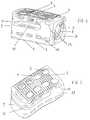
- La figure 1 représente une vue en perspective de la partie postérieure (7), de la paroi latérale longitudinale concave (12) et du partie supérieure (3) du corps de prothèse (1) de la prothèse déformable d'écartement de corps vertébraux.
- La figure 2 représente une vue en perspective de la partie supérieure (3), de la partie antérieure (9) et de la paroi latérale longitudinale concave (12) du corps de prothèse déformable d'écartement de corps vertébraux.
- La figure 3 représente une vue en perspective de la partie antérieure (9), de la partie supérieure (3) et de la paroi latérale longitudinale plate (11) du corps de prothèse déformable d'écartement de corps vertébraux.
- La figure 4 représente une vue en perspective de la partie postérieure (7), de la paroi latérale longitudinale plate (11) et de la partie supérieure (3) du corps de prothèse (1) déformable d'écartement de corps vertébraux.
- La figure 5 représente une photographie du corps de prothèse déformable d'écartement de corps vertébraux de la figure 1.
- La figure 6 représente une photographie du corps de prothèse déformable d'écartement de corps vertébraux de la figure 2.
- La figure 7 représente une photographie du corps de prothèse déformable d'écartement de corps vertébraux de la figure 3.
- La figure 8 représente une photographie du corps de prothèse déformable d'écartement de corps vertébraux de la figure 4.
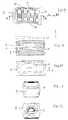
- La figure 9 représente une vue de la partie supérieure (3) du corps de prothèse déformable d'écartement de corps vertébraux et l'axe A-A correspond au plan sagittal.
- La figure 10 représente une coupe en section suivant l'axe A-A (plan sagittal) du corps de prothèse déformable d'écartement de corps vertébraux, l'axe X correspondant à l'axe longitudinal de la prothèse et l'axe Z correspondant à l'axe de translation du poussoir de réglage. La translation du poussoir de réglage (2) à l'intérieur du corps de prothèse (1) se faisant selon un axe incliné Z par rapport à l'axe longitudinal, les deux axes restant dans le plan sagittal.
- La figure 11 représente une vue de la paroi latérale longitudinale concave (12) et de la fente (10).
- La figure 12 représente une vue de la partie antérieure du corps de prothèse (1) déformable d'écartement de corps vertébraux.
- La figure 13 représente une vue de la partie postérieure (7) du corps de prothèse déformable d'écartement de corps vertébraux ainsi que deux orifices permettant de recevoir l'ancillaire et le maintien de l'ensemble ancillaire -poussoir de réglage -corps de prothèse.
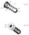
- La figure 14 représente une vue en perspective du poussoir de réglage (2) allongé servant de poussoir et comprenant une première partie (13) servant de butée, une deuxième partie (14) constituée par un pas de vis et une troisième partie (15) allongée perforée,
- La figure 15 représente une vue en perspective du poussoir de réglage (2) allongé ayant une tête circulaire (18) et une ouverture centrale hexagonale (19) pour l'insertion de l'ancillaire (90) lors de la mise en place du poussoir de réglage (2) à l'intérieur du corps de prothèse (1).
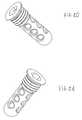
- La figure 16 représente une autre vue en perspective du poussoir de réglage allongé.
- La figure 17 représente encore une autre vue en perspective du poussoir de réglage allongé.
- La figure 18 représente une vue schématique de la figure 14.
- La figure 19 représente une vue schématique de la figure 15.
- La figure 20 représente une vue schématique de la figure 16.
- La figure 21 représente une vue schématique de la figure 17.
- La figure 22 représente une vue schématique du poussoir de réglage et un axe A-A.
- La figure 23 représente une vue schématique d'une coupe en section du poussoir de réglage suivant l'axe A-A.
- La figure 24 représente une vue schématique de la tête (18) du poussoir de réglage.
- La figure 25 représente une vue schématique de l'ancillaire (90) permettant l'insertion du poussoir de réglage (2) à l'intérieur du corps de prothèse (1).
- La figure 26 représente une vue en perspective de la prothèse déformable d'écartement de corps vertébraux constituée d'un corps de prothèse (1) et d'un poussoir de réglage (2) engagé dans ledit corps de prothèse (1).
- La figure 27 représente une prothèse déformable d'écartement de corps vertébraux en contact avec un corps vertébral supérieur (21) et inférieur (22).
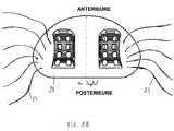
- La figure 28 représente une prothèse droite et une prothèse gauche (par rapport à un plan sagittal) en contact avec un corps vertébral inférieur (22) d'où partent des racines périphériques (23).
- Figure 1 shows a perspective view of the posterior portion (7), the concave longitudinal side wall (12) and the upper portion (3) of the prosthesis body (1) of the deformable vertebral body spacing prosthesis.
- Figure 2 shows a perspective view of the upper portion (3), the anterior portion (9) and the concave longitudinal sidewall (12) of the deformable vertebral body spacer prosthesis body.
- Fig. 3 is a perspective view of the anterior portion (9), the upper portion (3) and the flat longitudinal side wall (11) of the deformable vertebral body spacer prosthesis body.
- Figure 4 shows a perspective view of the posterior portion (7), the flat longitudinal side wall (11) and the upper portion (3) of the vertebral body deformable prosthesis body (1).
- FIG. 5 represents a photograph of the deformable prosthesis body of vertebral body spacing of FIG.
- FIG. 6 represents a photograph of the deformable prosthesis body of vertebral body spacing of FIG. 2.
- FIG. 7 shows a photograph of the vertebral body deformable prosthesis body of FIG. 3.
- FIG. 8 shows a photograph of the vertebral body deformable prosthesis body of FIG. 4.
- FIG. 9 represents a view of the upper part (3) of the deformable prosthesis body of vertebral body spacing and the axis AA corresponds to the sagittal plane.
- FIG. 10 represents a cross-section along the axis AA (sagittal plane) of the deformable prosthesis body of vertebral body spacing, the axis X corresponding to the longitudinal axis of the prosthesis and the axis Z corresponding to the translation axis of the adjustment pusher. The translation of the adjusting pusher (2) inside the prosthesis body (1) is effected along an inclined axis Z with respect to the longitudinal axis, the two axes remaining in the sagittal plane.
- Fig. 11 shows a view of the concave longitudinal sidewall (12) and the slot (10).
- Figure 12 shows a view of the anterior portion of the deformable prosthesis body (1) vertebral body spacing.
- FIG. 13 represents a view of the posterior part (7) of the deformable prosthesis body of vertebral body spacing as well as two orifices making it possible to receive the ancillary and the maintenance of the ancillary assembly -adjustment slider -prosthesis body .
- FIG. 14 represents a perspective view of the elongated adjusting pusher (2) serving as a pusher and comprising a first portion (13) serving as a stop, a second portion (14) constituted by a thread and a third portion (15). lengthened perforated,
- FIG. 15 represents a perspective view of the elongated adjusting pusher (2) having a circular head (18) and a hexagonal central opening (19) for the insertion of the ancillary device (90) during the introduction of the pusher adjusting device (2) inside the prosthesis body (1).
- Figure 16 shows another perspective view of the elongated adjustment pusher.
- Figure 17 shows yet another perspective view of the elongated adjustment pusher.
- Fig. 18 is a schematic view of Fig. 14.
- Fig. 19 is a schematic view of Fig. 15.
- Fig. 20 is a schematic view of Fig. 16.
- Fig. 21 is a schematic view of Fig. 17.
- Fig. 22 shows a schematic view of the adjustment pusher and an axis AA.
- FIG. 23 represents a schematic view of a cross-section of the adjustment pusher along the axis AA.
- Figure 24 shows a schematic view of the head (18) of the adjustment pusher.
- FIG. 25 represents a schematic view of the ancillary device (90) allowing insertion of the adjustment push-button (2) inside the prosthesis body (1).
- FIG. 26 represents a perspective view of the deformable vertebral body spacing prosthesis constituted by a prosthesis body (1) and an adjustment pusher (2) engaged in said prosthesis body (1).
- Figure 27 shows a deformable vertebral body spacing prosthesis in contact with an upper (21) and a lower (22) vertebral body.
- Figure 28 shows a right prosthesis and a left prosthesis (with respect to a sagittal plane) in contact with a lower vertebral body (22) from which peripheral roots (23) originate.
Conformément à l'invention le but est atteint grâce à une prothèse déformable d'écartement de corps vertébraux constituée d'un corps de prothèse (1) ajouré pouvant être de type « nid d'abeille» et d'un poussoir de réglage (2) allongé coopérant avec ce corps de prothèse (1), ledit corps de prothèse (1) comprenant une partie supérieure (3) convexe comportant des crans transversaux (4) en forme de dents et des lumières (5) de communication osseuse dans le corps de prothèse et permettant le maintien en place de la prothèse, une partie inférieure (6) plate comportant des crans transversaux (4) en forme de dents et des lumières (5) de migration osseuse dans le corps de prothèse, une partie postérieure (7) plate comprenant une ouverture circulaire longitudinale (8) recevant le poussoir de réglage (2), ladite ouverture circulaire longitudinale (8) de la partie postérieure (7) est taraudée à sa partie antérieure, une partie antérieure (9) arrondie pourvue d'une fente (10) séparant la partie supérieure (3) de la partie inférieure (6), une paroi latérale (11) longitudinale plate coupée en deux parties par la fente (10), une paroi latérale (12) longitudinale concave opposée à la paroi latérale (11) longitudinale plate également coupée en deux par la fente (10), la translation du poussoir de réglage (2) à l'intérieur du corps de prothèse (1) se faisant selon un axe incliné par rapport à l'axe longitudinal, les deux axes restant dans le plan sagittal.
La partie supérieure (3) et la partie inférieure (6) sont solidaires l'une de l'autre sur une partie de la longueur du corps de prothèse (1) et sont espacées l'une de l'autre par une fente (10) s'étendant de la partie solidarisée et débouchant à l'une des extrémités du corps et traversant le corps de prothèse (1) sur toute sa largeur. La fente (10) s'étend sur au moins la moitié, de préférence les deux tiers de la longueur du corps de prothèse (1).According to the invention, the goal is achieved by means of a deformable vertebral body spacing prosthesis consisting of a perforated prosthesis body (1) that can be of the "honeycomb" type and an adjustment pusher (2). ) lying cooperating with said prosthesis body (1), said prosthesis body (1) comprising a convex upper portion (3) having tooth-shaped transverse catches (4) and bone communication lumens (5) in the body prosthesis and allowing the prosthesis to remain in place, a flat lower portion (6) having tooth-like transverse notches (4) and bone migration lumens (5) in the prosthesis body, a posterior portion (7). ) comprising a longitudinal circular opening (8) receiving the adjusting pusher (2), said longitudinal circular opening (8) of the rear part (7) is threaded at its anterior part, a rounded front part (9) provided with a slot (10) separating the upper part (3) from the lower part (6), a flat longitudinal side wall (11) cut in two parts by the slot (10), a concave longitudinal side wall (12) opposite to the wall flat longitudinal side plate (11) also cut in half by the slot (10), the translation of the adjusting plunger (2) inside the prosthesis body (1) being along an axis inclined with respect to the longitudinal axis , the two axes remaining in the sagittal plane.
The upper portion (3) and the lower portion (6) are integral with each other over a portion of the length of the prosthesis body (1) and are spaced from one another by a slot (10). ) extending from the secured portion and opening at one end of the body and through the prosthesis body (1) over its entire width. The slot (10) extends over at least half, preferably two-thirds of the length of the prosthesis body (1).
La partie supérieure et la partie inférieure sont munies de crans de façon à éviter tout mouvement relatif entre la prothèse (ou écarteur intersomatique) et les plateaux des corps vertébraux entre lesquels la prothèse est insérée (mouvement avant-arrière et gauche-droite). De façon avantageuse la prothèse est munie de lumières pour favoriser la fusion entre les vertèbres et la migration osseuse.The upper part and the lower part are provided with notches so as to avoid any relative movement between the prosthesis (or intersomatic retractor) and the trays of the vertebral bodies between which the prosthesis is inserted (forward-backward movement and left-right movement). Advantageously, the prosthesis is provided with lights to promote fusion between the vertebrae and the bone migration.
La translation du poussoir de réglage se fait selon un axe incliné de 1 ° à 15° par rapport à l'axe longitudinal, de préférence de 1° à 10°. Les lumières (5) de la partie supérieure (3) et de la partie inférieure (6) sont alignées longitudinalement.The translation of the adjustment pusher is along an axis inclined from 1 ° to 15 ° with respect to the longitudinal axis, preferably from 1 ° to 10 °. The lights (5) of the upper part (3) and the lower part (6) are aligned longitudinally.
La partie supérieure (3) de la prothèse est déformable et est en contact avec un corps vertébral supérieur (21). Cette partie supérieure (3) épouse la concavité du corps vertébral supérieur selon deux directions : dans le plan sagittal et dans le plan frontal.The upper part (3) of the prosthesis is deformable and is in contact with an upper vertebral body (21). This upper part (3) matches the concavity of the upper vertebral body in two directions: in the sagittal plane and in the frontal plane.
La partie inférieure (6) de la prothèse est indéformable et est en contact avec un corps vertébral inférieur (22). La partie supérieure (3) et la partie inférieure (6) se retrouvent reliées par l'intermédiaire d'un pont dans la partie postérieure (7). La partie antérieure (9) et la partie postérieure (7) possèdent des arêtes et des extrémités non saillantes.The lower part (6) of the prosthesis is dimensionally stable and is in contact with a lower vertebral body (22). The upper part (3) and the lower part (6) are connected by means of a bridge in the rear part (7). The anterior portion (9) and the posterior portion (7) have ridges and non-projecting ends.
Le poussoir de réglage (2) allongé comprend une première partie (13) servant de butée, une deuxième partie (14) constituée par un pas de vis complémentaire à la partie taraudée de l'ouverture (8) de la partie postérieure du corps de prothèse et une troisième partie (15) allongée lisse qui peut présenter des lumières (17) traversantes possédant des bords arrondis lisses. Le poussoir de réglage (2) allongé est de forme cylindrique et possède un filetage de type male pour pouvoir être vissé dans le filetage de type femelle de l'ouverture de la partie postérieure plate. L'extrémité antérieure dudit poussoir de réglage (2) allongé peut être hémisphérique (16). Le poussoir de réglage (2) peut être creux afin de recevoir une croissance osseuse. Lorsque le poussoir de réglage (2) est entièrement à l'intérieur du corps de prothèse (1), la butée se trouvant à son extrémité postérieure est arrêtée par un épaulement (20) du corps de prothèse. La pénétration du poussoir de réglage (2) à l'intérieur du corps de prothèse (1) provoque la déformation par inclinaison de la partie supérieure (3). Le poussoir de réglage est muni de lumières (17) traversantes qui jouent le rôle de diffuseur du greffon pour optimiser l'ostéointégration.The elongated adjusting plunger (2) comprises a first portion (13) serving as an abutment, a second portion (14) constituted by a complementary screw thread to the threaded portion of the opening (8) of the rear part of the body of the body. prosthesis and a third elongated smooth portion (15) which may have through-lumens (17) having smooth rounded edges. The elongated adjusting plunger (2) is cylindrical in shape and has a male-type thread for being screwed into the female-type thread of the opening of the flat posterior portion. The front end of said elongated adjusting pusher (2) may be hemispherical (16). The adjustment pusher (2) may be hollow to receive bone growth. When the adjustment pusher (2) is entirely inside the prosthesis body (1), the abutment at its posterior end is stopped by a shoulder (20) of the prosthesis body. The penetration of the adjusting plunger (2) inside the prosthesis body (1) causes deformation by inclination of the upper part (3). The adjustment pusher is provided with through lights (17) which act as a diffuser of the graft to optimize osseointegration.
La prothèse de la présente invention est une prothèse droite ou une prothèse gauche (symétrie miroir par rapport au plan sagittal) pour s'adapter à l'anatomie des corps vertébraux et protéger les racines périphériques (23). Ainsi une ou deux prothèses (suivant l'orientation donnée aux prothèses) peuvent être en contact avec un corps vertébral supérieur (21) et un corps vertébral inférieur (22).The prosthesis of the present invention is a right prosthesis or a left prosthesis (mirror symmetry with respect to the sagittal plane) to adapt to the anatomy of the vertebral bodies and protect the peripheral roots (23). Thus one or two prostheses (depending on the orientation given to the prostheses) may be in contact with an upper vertebral body (21) and a lower vertebral body (22).
Cette prothèse comporte six surfaces asymétriques. Les caractéristiques géométriques de la prothèse ont été spécialement et minutieusement choisies pour éviter tout endommagement de la dure-mère, des racines périphériques (23) et de tout tissu sensible.This prosthesis has six asymmetrical surfaces. The geometric characteristics of the prosthesis have been specially and carefully chosen to prevent damage to the dura, peripheral roots (23) and any sensitive tissue.
La prothèse peut être réalisée en matière minérale ou synthétique par exemple en PEEK (poly ester ethyl carbon), en titane ou en tout autre matière acceptant les contraintes. La prothèse s'adapte à la morphologie par déformation tridimensionnelle (flexion et torsion) sous l'action simultanée d'un poussoir de réglage et des corps vertébraux. La déformation principale concerne la partie supérieure de la prothèse et permet d'obtenir un fort effet lordosant. La déformation de la prothèse permet de supprimer l'impaction de la prothèse dans les corps vertébraux.The prosthesis may be made of mineral or synthetic material for example PEEK (polyethyl ester), titanium or any other material accepting constraints. The prosthesis adapts to the morphology by three-dimensional deformation (flexion and torsion) under the simultaneous action of a regulating pusher and vertebral bodies. The main deformation concerns the upper part of the prosthesis and allows to obtain a strong lordosant effect. The deformation of the prosthesis makes it possible to eliminate the impaction of the prosthesis in the vertebral bodies.
L'insertion du poussoir de réglage se fait au moyen d'un ancillaire (dispositif de mise en place d'un écarteur de corps vertébraux) approprié comportant une poignée de préhension solidaire d'un tube, une tige suiveuse guidée et immobilisée à l'intérieur du tube et des moyens d'assemblage qui sont constitués d'une tige guidée à l'intérieur d'un premier alésage du tube, une molette permettant l'entraînement en rotation de la tige et d'un profil hexagonal prévu dans un second alésage dudit tube pour le blocage en rotation de la tige suiveuse à l'intérieur du tube.The insertion of the adjustment push-button is done by means of an appropriate ancillary device (device for placing a vertebral body spacer) comprising a gripping handle secured to a tube, a follower rod guided and immobilized at the same time. inside the tube and assembly means which consist of a rod guided inside a first bore of the tube, a wheel for driving in rotation of the rod and a hexagonal profile provided in a second boring said tube for locking in rotation of the follower rod inside the tube.
Claims (15)
Translated fromFrenchune partie supérieure (3) et une partie inférieure (6), ces deux parties étant solidaires l'une de l'autre sur une partie de la longueur du corps de prothèse (1) et étant espacées l'une de l'autre par une fente (10) s'étendant de la partie solidarisée (24) et débouchant à l'une des extrémités du corps et traversant le corps de prothèse (1) sur toute sa largeur,
le poussoir de réglage (2) étant engagé dans une ouverture (8) pratiquée dans ladite partie solidarisée (24) et s'étendant dans ladite fente (10), la position axiale du poussoir de réglage (2) par rapport au corps de prothèse (1) étant réglable pour régler l'écartement entre les parties non solidarisées du corps de prothèse (1), et l'axe longitudinal de ladite ouverture (8) et du poussoir de réglage (2) étant incliné par rapport à l'axe longitudinal central du corps de prothèse (1), les deux axes restant généralement dans un plan sagittal du corps de prothèse (1).Deformable prosthesis for separating the vertebral body, consisting of a prosthesis body (1) and an adjusting pusher (2) engaged in said prosthesis body (1), said prosthesis body (1) comprising
an upper part (3) and a lower part (6), these two parts being integral with one another over a part of the length of the prosthesis body (1) and being spaced from each other by a slot (10) extending from the secured portion (24) and opening at one end of the body and passing through the prosthesis body (1) over its entire width,
the adjustment pushbutton (2) being engaged in an opening (8) formed in said secured portion (24) and extending into said slot (10), the axial position of the adjusting pushbutton (2) relative to the prosthesis body (1) being adjustable to adjust the spacing between the unsecured portions of the prosthesis body (1), and the longitudinal axis of said opening (8) and the adjusting plunger (2) being inclined with respect to the axis longitudinal axis of the prosthesis body (1), the two axes generally remaining in a sagittal plane of the prosthesis body (1).
Priority Applications (5)
| Application Number | Priority Date | Filing Date | Title |
|---|---|---|---|
| AT05108139TATE369094T1 (en) | 2005-09-06 | 2005-09-06 | DEFORMABLE INTERVERBAL PROSTHESIS |
| DE602005001928TDE602005001928T2 (en) | 2005-09-06 | 2005-09-06 | Deformable intervertebral prosthesis |
| EP05108139AEP1698305B1 (en) | 2005-09-06 | 2005-09-06 | Deformable intervertebral prosthesis |
| ES05108139TES2292071T3 (en) | 2005-09-06 | 2005-09-06 | DEFESTABLE PROTESIS OF SEPARATION OF VERTEBRAL BODIES. |
| PCT/EP2006/065542WO2007028706A1 (en) | 2005-09-06 | 2006-08-22 | Deformable prosthesis for spacing vertebral bodies |
Applications Claiming Priority (1)
| Application Number | Priority Date | Filing Date | Title |
|---|---|---|---|
| EP05108139AEP1698305B1 (en) | 2005-09-06 | 2005-09-06 | Deformable intervertebral prosthesis |
Publications (2)
| Publication Number | Publication Date |
|---|---|
| EP1698305A1true EP1698305A1 (en) | 2006-09-06 |
| EP1698305B1 EP1698305B1 (en) | 2007-08-08 |
Family
ID=35044525
Family Applications (1)
| Application Number | Title | Priority Date | Filing Date |
|---|---|---|---|
| EP05108139AExpired - LifetimeEP1698305B1 (en) | 2005-09-06 | 2005-09-06 | Deformable intervertebral prosthesis |
Country Status (5)
| Country | Link |
|---|---|
| EP (1) | EP1698305B1 (en) |
| AT (1) | ATE369094T1 (en) |
| DE (1) | DE602005001928T2 (en) |
| ES (1) | ES2292071T3 (en) |
| WO (1) | WO2007028706A1 (en) |
Cited By (32)
| Publication number | Priority date | Publication date | Assignee | Title |
|---|---|---|---|---|
| DE102009014184A1 (en)* | 2008-11-07 | 2010-05-20 | Advanced Medical Technologies Ag | Implant for fusion of spinal segments |
| US9549824B2 (en) | 2011-06-17 | 2017-01-24 | Globus Medical, Inc. | Expandable spinal implant and flexible driver |
| US9883949B2 (en) | 2011-10-07 | 2018-02-06 | Pioneer Surgical Technology, Inc. | Intervertebral implant |
| US10376372B2 (en) | 2003-02-14 | 2019-08-13 | DePuy Synthes Products, Inc. | In-situ formed intervertebral fusion device and method |
| US10390963B2 (en) | 2006-12-07 | 2019-08-27 | DePuy Synthes Products, Inc. | Intervertebral implant |
| US10398563B2 (en) | 2017-05-08 | 2019-09-03 | Medos International Sarl | Expandable cage |
| US10433881B2 (en) | 2004-03-06 | 2019-10-08 | DePuy Synthes Products, Inc. | Dynamized interspinal implant |
| US10433974B2 (en) | 2003-06-30 | 2019-10-08 | DePuy Synthes Products, Inc. | Intervertebral implant with conformable endplate |
| US10433977B2 (en) | 2008-01-17 | 2019-10-08 | DePuy Synthes Products, Inc. | Expandable intervertebral implant and associated method of manufacturing the same |
| US10449056B2 (en) | 2008-04-05 | 2019-10-22 | DePuy Synthes Products, Inc. | Expandable intervertebral implant |
| USD907771S1 (en) | 2017-10-09 | 2021-01-12 | Pioneer Surgical Technology, Inc. | Intervertebral implant |
| US10888433B2 (en) | 2016-12-14 | 2021-01-12 | DePuy Synthes Products, Inc. | Intervertebral implant inserter and related methods |
| US10940016B2 (en) | 2017-07-05 | 2021-03-09 | Medos International Sarl | Expandable intervertebral fusion cage |
| US10966840B2 (en) | 2010-06-24 | 2021-04-06 | DePuy Synthes Products, Inc. | Enhanced cage insertion assembly |
| US11147682B2 (en) | 2017-09-08 | 2021-10-19 | Pioneer Surgical Technology, Inc. | Intervertebral implants, instruments, and methods |
| US11344424B2 (en) | 2017-06-14 | 2022-05-31 | Medos International Sarl | Expandable intervertebral implant and related methods |
| US11426286B2 (en) | 2020-03-06 | 2022-08-30 | Eit Emerging Implant Technologies Gmbh | Expandable intervertebral implant |
| US11446156B2 (en) | 2018-10-25 | 2022-09-20 | Medos International Sarl | Expandable intervertebral implant, inserter instrument, and related methods |
| US11452607B2 (en) | 2010-10-11 | 2022-09-27 | DePuy Synthes Products, Inc. | Expandable interspinous process spacer implant |
| US11497619B2 (en) | 2013-03-07 | 2022-11-15 | DePuy Synthes Products, Inc. | Intervertebral implant |
| US11510788B2 (en) | 2016-06-28 | 2022-11-29 | Eit Emerging Implant Technologies Gmbh | Expandable, angularly adjustable intervertebral cages |
| US11596523B2 (en) | 2016-06-28 | 2023-03-07 | Eit Emerging Implant Technologies Gmbh | Expandable and angularly adjustable articulating intervertebral cages |
| US11607321B2 (en) | 2009-12-10 | 2023-03-21 | DePuy Synthes Products, Inc. | Bellows-like expandable interbody fusion cage |
| US11612491B2 (en) | 2009-03-30 | 2023-03-28 | DePuy Synthes Products, Inc. | Zero profile spinal fusion cage |
| US11622868B2 (en) | 2007-06-26 | 2023-04-11 | DePuy Synthes Products, Inc. | Highly lordosed fusion cage |
| US11654033B2 (en) | 2010-06-29 | 2023-05-23 | DePuy Synthes Products, Inc. | Distractible intervertebral implant |
| US11752009B2 (en) | 2021-04-06 | 2023-09-12 | Medos International Sarl | Expandable intervertebral fusion cage |
| US11850160B2 (en) | 2021-03-26 | 2023-12-26 | Medos International Sarl | Expandable lordotic intervertebral fusion cage |
| US11911287B2 (en) | 2010-06-24 | 2024-02-27 | DePuy Synthes Products, Inc. | Lateral spondylolisthesis reduction cage |
| USRE49973E1 (en) | 2013-02-28 | 2024-05-21 | DePuy Synthes Products, Inc. | Expandable intervertebral implant, system, kit and method |
| US12090064B2 (en) | 2022-03-01 | 2024-09-17 | Medos International Sarl | Stabilization members for expandable intervertebral implants, and related systems and methods |
| US12440346B2 (en) | 2023-03-31 | 2025-10-14 | DePuy Synthes Products, Inc. | Expandable intervertebral implant |
Families Citing this family (15)
| Publication number | Priority date | Publication date | Assignee | Title |
|---|---|---|---|---|
| US6793678B2 (en) | 2002-06-27 | 2004-09-21 | Depuy Acromed, Inc. | Prosthetic intervertebral motion disc having dampening |
| KR101687435B1 (en) | 2009-07-06 | 2016-12-19 | 신세스 게엠바하 | Expandable fixation assemblies |
| US8906028B2 (en) | 2009-09-18 | 2014-12-09 | Spinal Surgical Strategies, Llc | Bone graft delivery device and method of using the same |
| US10245159B1 (en) | 2009-09-18 | 2019-04-02 | Spinal Surgical Strategies, Llc | Bone graft delivery system and method for using same |
| US10973656B2 (en) | 2009-09-18 | 2021-04-13 | Spinal Surgical Strategies, Inc. | Bone graft delivery system and method for using same |
| EP2547292B1 (en) | 2010-03-16 | 2019-04-24 | Pinnacle Spine Group, LLC | Ntervertebral implants and graft delivery systems |
| US9380932B1 (en) | 2011-11-02 | 2016-07-05 | Pinnacle Spine Group, Llc | Retractor devices for minimally invasive access to the spine |
| EP2877127B1 (en) | 2012-07-26 | 2019-08-21 | Synthes GmbH | Expandable implant |
| WO2014159739A1 (en) | 2013-03-14 | 2014-10-02 | Pinnacle Spine Group, Llc | Interbody implants and graft delivery systems |
| US9788971B1 (en) | 2013-05-22 | 2017-10-17 | Nuvasive, Inc. | Expandable fusion implant and related methods |
| US9801734B1 (en) | 2013-08-09 | 2017-10-31 | Nuvasive, Inc. | Lordotic expandable interbody implant |
| US11426290B2 (en) | 2015-03-06 | 2022-08-30 | DePuy Synthes Products, Inc. | Expandable intervertebral implant, system, kit and method |
| US9913727B2 (en) | 2015-07-02 | 2018-03-13 | Medos International Sarl | Expandable implant |
| US10537436B2 (en) | 2016-11-01 | 2020-01-21 | DePuy Synthes Products, Inc. | Curved expandable cage |
| WO2023285675A1 (en) | 2021-07-16 | 2023-01-19 | Blue Ocean Spine Gmbh | Adjustable intervertebral cage, associated instrument and manufacturing process therefor |
Citations (9)
| Publication number | Priority date | Publication date | Assignee | Title |
|---|---|---|---|---|
| DE4416605C1 (en)* | 1994-05-11 | 1995-06-08 | Aesculap Ag | Inter-vertebral implant |
| FR2753368A1 (en) | 1996-09-13 | 1998-03-20 | Chauvin Jean Luc | EXPANSIONAL OSTEOSYNTHESIS CAGE |
| FR2803741A1 (en) | 2000-01-13 | 2001-07-20 | Jean Claude Bouvet | Intersomatic cage for replacing damaged intervertebral disc has two hinged arms with spikes, deployed by threaded rotating wedge |
| EP1138285A1 (en)* | 2000-03-29 | 2001-10-04 | Implant Design AG | Spinal cage for insertion between the vertebraes of the spine |
| US6454807B1 (en)* | 2000-11-30 | 2002-09-24 | Roger P. Jackson | Articulated expandable spinal fusion cage system |
| EP1290985A2 (en) | 2001-08-16 | 2003-03-12 | Iql Industrias Quirurgicas De Levante S.L. | Intersomatic cage for posterior fusion surgery to the lumbar column and for surgery involving the insertion of a transforaminal implant |
| US6685742B1 (en)* | 2002-11-12 | 2004-02-03 | Roger P. Jackson | Articulated anterior expandable spinal fusion cage system |
| FR2843017A1 (en)* | 2002-08-01 | 2004-02-06 | Biomet Merck France | INTER-SOMATIC IMPLANT |
| EP1532949A1 (en) | 2003-11-20 | 2005-05-25 | Kyungwon Medical Co., Ltd. | Expandable intervertebral fusion cage |
- 2005
- 2005-09-06DEDE602005001928Tpatent/DE602005001928T2/ennot_activeExpired - Fee Related
- 2005-09-06EPEP05108139Apatent/EP1698305B1/ennot_activeExpired - Lifetime
- 2005-09-06ATAT05108139Tpatent/ATE369094T1/ennot_activeIP Right Cessation
- 2005-09-06ESES05108139Tpatent/ES2292071T3/ennot_activeExpired - Lifetime
- 2006
- 2006-08-22WOPCT/EP2006/065542patent/WO2007028706A1/enactiveApplication Filing
Patent Citations (9)
| Publication number | Priority date | Publication date | Assignee | Title |
|---|---|---|---|---|
| DE4416605C1 (en)* | 1994-05-11 | 1995-06-08 | Aesculap Ag | Inter-vertebral implant |
| FR2753368A1 (en) | 1996-09-13 | 1998-03-20 | Chauvin Jean Luc | EXPANSIONAL OSTEOSYNTHESIS CAGE |
| FR2803741A1 (en) | 2000-01-13 | 2001-07-20 | Jean Claude Bouvet | Intersomatic cage for replacing damaged intervertebral disc has two hinged arms with spikes, deployed by threaded rotating wedge |
| EP1138285A1 (en)* | 2000-03-29 | 2001-10-04 | Implant Design AG | Spinal cage for insertion between the vertebraes of the spine |
| US6454807B1 (en)* | 2000-11-30 | 2002-09-24 | Roger P. Jackson | Articulated expandable spinal fusion cage system |
| EP1290985A2 (en) | 2001-08-16 | 2003-03-12 | Iql Industrias Quirurgicas De Levante S.L. | Intersomatic cage for posterior fusion surgery to the lumbar column and for surgery involving the insertion of a transforaminal implant |
| FR2843017A1 (en)* | 2002-08-01 | 2004-02-06 | Biomet Merck France | INTER-SOMATIC IMPLANT |
| US6685742B1 (en)* | 2002-11-12 | 2004-02-03 | Roger P. Jackson | Articulated anterior expandable spinal fusion cage system |
| EP1532949A1 (en) | 2003-11-20 | 2005-05-25 | Kyungwon Medical Co., Ltd. | Expandable intervertebral fusion cage |
Cited By (67)
| Publication number | Priority date | Publication date | Assignee | Title |
|---|---|---|---|---|
| US10405986B2 (en) | 2003-02-14 | 2019-09-10 | DePuy Synthes Products, Inc. | In-situ formed intervertebral fusion device and method |
| US10433971B2 (en) | 2003-02-14 | 2019-10-08 | DePuy Synthes Products, Inc. | In-situ formed intervertebral fusion device and method |
| US10376372B2 (en) | 2003-02-14 | 2019-08-13 | DePuy Synthes Products, Inc. | In-situ formed intervertebral fusion device and method |
| US10420651B2 (en) | 2003-02-14 | 2019-09-24 | DePuy Synthes Products, Inc. | In-situ formed intervertebral fusion device and method |
| US10433974B2 (en) | 2003-06-30 | 2019-10-08 | DePuy Synthes Products, Inc. | Intervertebral implant with conformable endplate |
| US10433881B2 (en) | 2004-03-06 | 2019-10-08 | DePuy Synthes Products, Inc. | Dynamized interspinal implant |
| US10390963B2 (en) | 2006-12-07 | 2019-08-27 | DePuy Synthes Products, Inc. | Intervertebral implant |
| US11497618B2 (en) | 2006-12-07 | 2022-11-15 | DePuy Synthes Products, Inc. | Intervertebral implant |
| US10398566B2 (en) | 2006-12-07 | 2019-09-03 | DePuy Synthes Products, Inc. | Intervertebral implant |
| US11660206B2 (en) | 2006-12-07 | 2023-05-30 | DePuy Synthes Products, Inc. | Intervertebral implant |
| US11642229B2 (en) | 2006-12-07 | 2023-05-09 | DePuy Synthes Products, Inc. | Intervertebral implant |
| US11712345B2 (en) | 2006-12-07 | 2023-08-01 | DePuy Synthes Products, Inc. | Intervertebral implant |
| US10583015B2 (en) | 2006-12-07 | 2020-03-10 | DePuy Synthes Products, Inc. | Intervertebral implant |
| US11273050B2 (en) | 2006-12-07 | 2022-03-15 | DePuy Synthes Products, Inc. | Intervertebral implant |
| US11622868B2 (en) | 2007-06-26 | 2023-04-11 | DePuy Synthes Products, Inc. | Highly lordosed fusion cage |
| US10433977B2 (en) | 2008-01-17 | 2019-10-08 | DePuy Synthes Products, Inc. | Expandable intervertebral implant and associated method of manufacturing the same |
| US10449058B2 (en) | 2008-01-17 | 2019-10-22 | DePuy Synthes Products, Inc. | Expandable intervertebral implant and associated method of manufacturing the same |
| US11737881B2 (en) | 2008-01-17 | 2023-08-29 | DePuy Synthes Products, Inc. | Expandable intervertebral implant and associated method of manufacturing the same |
| US12011361B2 (en) | 2008-04-05 | 2024-06-18 | DePuy Synthes Products, Inc. | Expandable intervertebral implant |
| US11602438B2 (en) | 2008-04-05 | 2023-03-14 | DePuy Synthes Products, Inc. | Expandable intervertebral implant |
| US11617655B2 (en) | 2008-04-05 | 2023-04-04 | DePuy Synthes Products, Inc. | Expandable intervertebral implant |
| US12023255B2 (en) | 2008-04-05 | 2024-07-02 | DePuy Synthes Products, Inc. | Expandable inter vertebral implant |
| US11712341B2 (en) | 2008-04-05 | 2023-08-01 | DePuy Synthes Products, Inc. | Expandable intervertebral implant |
| US10449056B2 (en) | 2008-04-05 | 2019-10-22 | DePuy Synthes Products, Inc. | Expandable intervertebral implant |
| US11712342B2 (en) | 2008-04-05 | 2023-08-01 | DePuy Synthes Products, Inc. | Expandable intervertebral implant |
| US11707359B2 (en) | 2008-04-05 | 2023-07-25 | DePuy Synthes Products, Inc. | Expandable intervertebral implant |
| US11701234B2 (en) | 2008-04-05 | 2023-07-18 | DePuy Synthes Products, Inc. | Expandable intervertebral implant |
| DE102009014184A1 (en)* | 2008-11-07 | 2010-05-20 | Advanced Medical Technologies Ag | Implant for fusion of spinal segments |
| US11612491B2 (en) | 2009-03-30 | 2023-03-28 | DePuy Synthes Products, Inc. | Zero profile spinal fusion cage |
| US12097124B2 (en) | 2009-03-30 | 2024-09-24 | DePuy Synthes Products, Inc. | Zero profile spinal fusion cage |
| US11607321B2 (en) | 2009-12-10 | 2023-03-21 | DePuy Synthes Products, Inc. | Bellows-like expandable interbody fusion cage |
| US12318304B2 (en) | 2010-06-24 | 2025-06-03 | DePuy Synthes Products, Inc. | Lateral spondylolisthesis reduction cage |
| US11911287B2 (en) | 2010-06-24 | 2024-02-27 | DePuy Synthes Products, Inc. | Lateral spondylolisthesis reduction cage |
| US11872139B2 (en) | 2010-06-24 | 2024-01-16 | DePuy Synthes Products, Inc. | Enhanced cage insertion assembly |
| US10966840B2 (en) | 2010-06-24 | 2021-04-06 | DePuy Synthes Products, Inc. | Enhanced cage insertion assembly |
| US11654033B2 (en) | 2010-06-29 | 2023-05-23 | DePuy Synthes Products, Inc. | Distractible intervertebral implant |
| US11452607B2 (en) | 2010-10-11 | 2022-09-27 | DePuy Synthes Products, Inc. | Expandable interspinous process spacer implant |
| US9549824B2 (en) | 2011-06-17 | 2017-01-24 | Globus Medical, Inc. | Expandable spinal implant and flexible driver |
| US10869767B2 (en) | 2011-10-07 | 2020-12-22 | Pioneer Surgical Technology, Inc. | Intervertebral implant |
| US11654031B2 (en) | 2011-10-07 | 2023-05-23 | Pioneer Surgical Technology, Inc. | Intervertebral implant |
| US9883949B2 (en) | 2011-10-07 | 2018-02-06 | Pioneer Surgical Technology, Inc. | Intervertebral implant |
| USRE49973E1 (en) | 2013-02-28 | 2024-05-21 | DePuy Synthes Products, Inc. | Expandable intervertebral implant, system, kit and method |
| US11850164B2 (en) | 2013-03-07 | 2023-12-26 | DePuy Synthes Products, Inc. | Intervertebral implant |
| US11497619B2 (en) | 2013-03-07 | 2022-11-15 | DePuy Synthes Products, Inc. | Intervertebral implant |
| US11596523B2 (en) | 2016-06-28 | 2023-03-07 | Eit Emerging Implant Technologies Gmbh | Expandable and angularly adjustable articulating intervertebral cages |
| US11510788B2 (en) | 2016-06-28 | 2022-11-29 | Eit Emerging Implant Technologies Gmbh | Expandable, angularly adjustable intervertebral cages |
| US12433757B2 (en) | 2016-06-28 | 2025-10-07 | Eit Emerging Implant Technologies Gmbh | Expandable, angularly adjustable and articulating intervertebral cages |
| US12390343B2 (en) | 2016-06-28 | 2025-08-19 | Eit Emerging Implant Technologies Gmbh | Expandable, angularly adjustable intervertebral cages |
| US11596522B2 (en) | 2016-06-28 | 2023-03-07 | Eit Emerging Implant Technologies Gmbh | Expandable and angularly adjustable intervertebral cages with articulating joint |
| US10888433B2 (en) | 2016-12-14 | 2021-01-12 | DePuy Synthes Products, Inc. | Intervertebral implant inserter and related methods |
| US10398563B2 (en) | 2017-05-08 | 2019-09-03 | Medos International Sarl | Expandable cage |
| US12427031B2 (en) | 2017-05-08 | 2025-09-30 | Medos International Sarl | Expandable cage |
| US11446155B2 (en) | 2017-05-08 | 2022-09-20 | Medos International Sarl | Expandable cage |
| US11344424B2 (en) | 2017-06-14 | 2022-05-31 | Medos International Sarl | Expandable intervertebral implant and related methods |
| US10940016B2 (en) | 2017-07-05 | 2021-03-09 | Medos International Sarl | Expandable intervertebral fusion cage |
| US11147682B2 (en) | 2017-09-08 | 2021-10-19 | Pioneer Surgical Technology, Inc. | Intervertebral implants, instruments, and methods |
| US12279965B2 (en) | 2017-09-08 | 2025-04-22 | Xtant Medical Holdings, Inc. | Intervertebral implants, instruments, and methods |
| USD968613S1 (en) | 2017-10-09 | 2022-11-01 | Pioneer Surgical Technology, Inc. | Intervertebral implant |
| USD907771S1 (en) | 2017-10-09 | 2021-01-12 | Pioneer Surgical Technology, Inc. | Intervertebral implant |
| US11446156B2 (en) | 2018-10-25 | 2022-09-20 | Medos International Sarl | Expandable intervertebral implant, inserter instrument, and related methods |
| US11806245B2 (en) | 2020-03-06 | 2023-11-07 | Eit Emerging Implant Technologies Gmbh | Expandable intervertebral implant |
| US11426286B2 (en) | 2020-03-06 | 2022-08-30 | Eit Emerging Implant Technologies Gmbh | Expandable intervertebral implant |
| US11850160B2 (en) | 2021-03-26 | 2023-12-26 | Medos International Sarl | Expandable lordotic intervertebral fusion cage |
| US11752009B2 (en) | 2021-04-06 | 2023-09-12 | Medos International Sarl | Expandable intervertebral fusion cage |
| US12023258B2 (en) | 2021-04-06 | 2024-07-02 | Medos International Sarl | Expandable intervertebral fusion cage |
| US12090064B2 (en) | 2022-03-01 | 2024-09-17 | Medos International Sarl | Stabilization members for expandable intervertebral implants, and related systems and methods |
| US12440346B2 (en) | 2023-03-31 | 2025-10-14 | DePuy Synthes Products, Inc. | Expandable intervertebral implant |
Also Published As
| Publication number | Publication date |
|---|---|
| WO2007028706A1 (en) | 2007-03-15 |
| ATE369094T1 (en) | 2007-08-15 |
| ES2292071T3 (en) | 2008-03-01 |
| EP1698305B1 (en) | 2007-08-08 |
| DE602005001928D1 (en) | 2007-09-20 |
| DE602005001928T2 (en) | 2008-04-30 |
Similar Documents
| Publication | Publication Date | Title |
|---|---|---|
| EP1698305B1 (en) | Deformable intervertebral prosthesis | |
| EP1372541B1 (en) | Stabilised interbody fusion system for vertebrae | |
| CA2299166C (en) | Implant, in particular front cervical plate | |
| EP0869753B1 (en) | Interbody vertebral implant | |
| CA2266126C (en) | Expansive osteosynthesis sheath | |
| EP1337193B1 (en) | Intervertebral stabilising device | |
| CA2292748C (en) | Multidirectional adaptable vertebral osteosynthesis device with reduced space requirement | |
| EP0721314B1 (en) | Apparatus for resectioning knee condyles, enabling a prosthesis to be fitted | |
| EP2385813B1 (en) | Orthopaedic implant for arthroplasty of the fingers | |
| EP1795136B1 (en) | Apparatus for dynamic stabilisation of the spine | |
| FR2827503A1 (en) | Modular reconstruction assembly for hip joint prosthesis has acetabular cavity support plate fixed with pile screws, spacer and metal cup | |
| EP1997449A2 (en) | Device and assembly for rear dynamic guidance of the spine and spine treatment system comprising such a device | |
| EP0471821A1 (en) | PROSTHESIS FOR INTERVERTEBRAL DISCS AND ITS IMPLEMENTATION INSTRUMENTS. | |
| FR2718635A1 (en) | Vertebral cervical prosthesis | |
| FR2893838A1 (en) | Intervertebral disc prosthesis for insertion in spinal column, has osseous anchoring element positioned near peripheral edge of preset plate among pair of plates such that curved articulation surface is formed on preset plate | |
| EP0767636A1 (en) | Vertebral implant | |
| FR2763836A1 (en) | CERVICAL INTERVERTEBRAL CAGE | |
| FR2914180A1 (en) | EXPANSIVE CAGE FOR VERTEBRAL SURGERY. | |
| WO2001039678A1 (en) | Intervertebral stabilising device | |
| FR2844180A1 (en) | Connection element for spinal fixation system designed to link at least two implantable connection assemblies, is formed from a helicoidal spring part and a polymeric material support part | |
| FR2813519A1 (en) | Intersomatic spinal implant, has supple structure to hold graft under pressure against surfaces of adjacent vertebrae | |
| WO2014114853A1 (en) | Self-extending implant | |
| FR2915367A1 (en) | ENHANCED INTERVERTEBRAL IMPULSE IMPLANT TO ENHANCE CERTAIN INTERBREAK MOVEMENTS | |
| FR2736538A1 (en) | Intersomatic cage for filling intervertebral space between the lumbar vertebrae | |
| FR2790941A1 (en) | INSTRUMENTATION OF RACHIDIAN OSTEOSYNTHESIS WITH PLATE AND PEDICULAR SCREW OR TRANSVERSE CONNECTOR BETWEEN A VERTEBRAL ROD AND A PEDICULAR SCREW |
Legal Events
| Date | Code | Title | Description |
|---|---|---|---|
| PUAI | Public reference made under article 153(3) epc to a published international application that has entered the european phase | Free format text:ORIGINAL CODE: 0009012 | |
| 17P | Request for examination filed | Effective date:20050906 | |
| AK | Designated contracting states | Kind code of ref document:A1 Designated state(s):AT BE BG CH CY CZ DE DK EE ES FI FR GB GR HU IE IS IT LI LT LU LV MC NL PL PT RO SE SI SK TR | |
| AX | Request for extension of the european patent | Extension state:AL BA HR MK YU | |
| RAP1 | Party data changed (applicant data changed or rights of an application transferred) | Owner name:ORTHOPAEDIC & SPINE DEVELOPMENT | |
| GRAP | Despatch of communication of intention to grant a patent | Free format text:ORIGINAL CODE: EPIDOSNIGR1 | |
| AKX | Designation fees paid | Designated state(s):AT BE BG CH CY CZ DE DK EE ES FI FR GB GR HU IE IS IT LI LT LU LV MC NL PL PT RO SE SI SK TR | |
| GRAS | Grant fee paid | Free format text:ORIGINAL CODE: EPIDOSNIGR3 | |
| GRAA | (expected) grant | Free format text:ORIGINAL CODE: 0009210 | |
| AK | Designated contracting states | Kind code of ref document:B1 Designated state(s):AT BE BG CH CY CZ DE DK EE ES FI FR GB GR HU IE IS IT LI LT LU LV MC NL PL PT RO SE SI SK TR | |
| REG | Reference to a national code | Ref country code:GB Ref legal event code:FG4D Free format text:NOT ENGLISH | |
| REG | Reference to a national code | Ref country code:CH Ref legal event code:EP | |
| REG | Reference to a national code | Ref country code:IE Ref legal event code:FG4D Free format text:LANGUAGE OF EP DOCUMENT: FRENCH | |
| REF | Corresponds to: | Ref document number:602005001928 Country of ref document:DE Date of ref document:20070920 Kind code of ref document:P | |
| PGFP | Annual fee paid to national office [announced via postgrant information from national office to epo] | Ref country code:DE Payment date:20070921 Year of fee payment:3 | |
| PG25 | Lapsed in a contracting state [announced via postgrant information from national office to epo] | Ref country code:LT Free format text:LAPSE BECAUSE OF FAILURE TO SUBMIT A TRANSLATION OF THE DESCRIPTION OR TO PAY THE FEE WITHIN THE PRESCRIBED TIME-LIMIT Effective date:20070808 Ref country code:NL Free format text:LAPSE BECAUSE OF FAILURE TO SUBMIT A TRANSLATION OF THE DESCRIPTION OR TO PAY THE FEE WITHIN THE PRESCRIBED TIME-LIMIT Effective date:20070808 Ref country code:IS Free format text:LAPSE BECAUSE OF FAILURE TO SUBMIT A TRANSLATION OF THE DESCRIPTION OR TO PAY THE FEE WITHIN THE PRESCRIBED TIME-LIMIT Effective date:20071208 Ref country code:BG Free format text:LAPSE BECAUSE OF FAILURE TO SUBMIT A TRANSLATION OF THE DESCRIPTION OR TO PAY THE FEE WITHIN THE PRESCRIBED TIME-LIMIT Effective date:20071108 Ref country code:FI Free format text:LAPSE BECAUSE OF FAILURE TO SUBMIT A TRANSLATION OF THE DESCRIPTION OR TO PAY THE FEE WITHIN THE PRESCRIBED TIME-LIMIT Effective date:20070808 | |
| NLV1 | Nl: lapsed or annulled due to failure to fulfill the requirements of art. 29p and 29m of the patents act | ||
| PG25 | Lapsed in a contracting state [announced via postgrant information from national office to epo] | Ref country code:PL Free format text:LAPSE BECAUSE OF FAILURE TO SUBMIT A TRANSLATION OF THE DESCRIPTION OR TO PAY THE FEE WITHIN THE PRESCRIBED TIME-LIMIT Effective date:20070808 Ref country code:AT Free format text:LAPSE BECAUSE OF FAILURE TO SUBMIT A TRANSLATION OF THE DESCRIPTION OR TO PAY THE FEE WITHIN THE PRESCRIBED TIME-LIMIT Effective date:20070808 | |
| REG | Reference to a national code | Ref country code:ES Ref legal event code:FG2A Ref document number:2292071 Country of ref document:ES Kind code of ref document:T3 | |
| GBV | Gb: ep patent (uk) treated as always having been void in accordance with gb section 77(7)/1977 [no translation filed] | Effective date:20070808 | |
| BERE | Be: lapsed | Owner name:ORTHOPAEDIC & SPINE DEVELOPMENT Effective date:20070930 | |
| PG25 | Lapsed in a contracting state [announced via postgrant information from national office to epo] | Ref country code:LV Free format text:LAPSE BECAUSE OF FAILURE TO SUBMIT A TRANSLATION OF THE DESCRIPTION OR TO PAY THE FEE WITHIN THE PRESCRIBED TIME-LIMIT Effective date:20070808 | |
| REG | Reference to a national code | Ref country code:IE Ref legal event code:FD4D | |
| PG25 | Lapsed in a contracting state [announced via postgrant information from national office to epo] | Ref country code:DK Free format text:LAPSE BECAUSE OF FAILURE TO SUBMIT A TRANSLATION OF THE DESCRIPTION OR TO PAY THE FEE WITHIN THE PRESCRIBED TIME-LIMIT Effective date:20070808 Ref country code:GR Free format text:LAPSE BECAUSE OF FAILURE TO SUBMIT A TRANSLATION OF THE DESCRIPTION OR TO PAY THE FEE WITHIN THE PRESCRIBED TIME-LIMIT Effective date:20071109 Ref country code:MC Free format text:LAPSE BECAUSE OF NON-PAYMENT OF DUE FEES Effective date:20070930 | |
| PG25 | Lapsed in a contracting state [announced via postgrant information from national office to epo] | Ref country code:GB Free format text:LAPSE BECAUSE OF FAILURE TO SUBMIT A TRANSLATION OF THE DESCRIPTION OR TO PAY THE FEE WITHIN THE PRESCRIBED TIME-LIMIT Effective date:20070808 Ref country code:IE Free format text:LAPSE BECAUSE OF FAILURE TO SUBMIT A TRANSLATION OF THE DESCRIPTION OR TO PAY THE FEE WITHIN THE PRESCRIBED TIME-LIMIT Effective date:20070808 Ref country code:PT Free format text:LAPSE BECAUSE OF FAILURE TO SUBMIT A TRANSLATION OF THE DESCRIPTION OR TO PAY THE FEE WITHIN THE PRESCRIBED TIME-LIMIT Effective date:20080108 Ref country code:SK Free format text:LAPSE BECAUSE OF FAILURE TO SUBMIT A TRANSLATION OF THE DESCRIPTION OR TO PAY THE FEE WITHIN THE PRESCRIBED TIME-LIMIT Effective date:20070808 Ref country code:CZ Free format text:LAPSE BECAUSE OF FAILURE TO SUBMIT A TRANSLATION OF THE DESCRIPTION OR TO PAY THE FEE WITHIN THE PRESCRIBED TIME-LIMIT Effective date:20070808 | |
| PLBE | No opposition filed within time limit | Free format text:ORIGINAL CODE: 0009261 | |
| STAA | Information on the status of an ep patent application or granted ep patent | Free format text:STATUS: NO OPPOSITION FILED WITHIN TIME LIMIT | |
| PG25 | Lapsed in a contracting state [announced via postgrant information from national office to epo] | Ref country code:SE Free format text:LAPSE BECAUSE OF FAILURE TO SUBMIT A TRANSLATION OF THE DESCRIPTION OR TO PAY THE FEE WITHIN THE PRESCRIBED TIME-LIMIT Effective date:20071108 Ref country code:RO Free format text:LAPSE BECAUSE OF FAILURE TO SUBMIT A TRANSLATION OF THE DESCRIPTION OR TO PAY THE FEE WITHIN THE PRESCRIBED TIME-LIMIT Effective date:20070808 | |
| 26N | No opposition filed | Effective date:20080509 | |
| PG25 | Lapsed in a contracting state [announced via postgrant information from national office to epo] | Ref country code:BE Free format text:LAPSE BECAUSE OF NON-PAYMENT OF DUE FEES Effective date:20070930 | |
| REG | Reference to a national code | Ref country code:FR Ref legal event code:ST Effective date:20080930 | |
| REG | Reference to a national code | Ref country code:ES Ref legal event code:FD2A Effective date:20070907 | |
| PG25 | Lapsed in a contracting state [announced via postgrant information from national office to epo] | Ref country code:ES Free format text:LAPSE BECAUSE OF NON-PAYMENT OF DUE FEES Effective date:20070907 Ref country code:EE Free format text:LAPSE BECAUSE OF FAILURE TO SUBMIT A TRANSLATION OF THE DESCRIPTION OR TO PAY THE FEE WITHIN THE PRESCRIBED TIME-LIMIT Effective date:20070808 | |
| PG25 | Lapsed in a contracting state [announced via postgrant information from national office to epo] | Ref country code:FR Free format text:LAPSE BECAUSE OF NON-PAYMENT OF DUE FEES Effective date:20071001 | |
| PG25 | Lapsed in a contracting state [announced via postgrant information from national office to epo] | Ref country code:SI Free format text:LAPSE BECAUSE OF FAILURE TO SUBMIT A TRANSLATION OF THE DESCRIPTION OR TO PAY THE FEE WITHIN THE PRESCRIBED TIME-LIMIT Effective date:20070808 | |
| PG25 | Lapsed in a contracting state [announced via postgrant information from national office to epo] | Ref country code:CY Free format text:LAPSE BECAUSE OF FAILURE TO SUBMIT A TRANSLATION OF THE DESCRIPTION OR TO PAY THE FEE WITHIN THE PRESCRIBED TIME-LIMIT Effective date:20070808 | |
| PG25 | Lapsed in a contracting state [announced via postgrant information from national office to epo] | Ref country code:DE Free format text:LAPSE BECAUSE OF NON-PAYMENT OF DUE FEES Effective date:20090401 Ref country code:LU Free format text:LAPSE BECAUSE OF NON-PAYMENT OF DUE FEES Effective date:20070906 | |
| PG25 | Lapsed in a contracting state [announced via postgrant information from national office to epo] | Ref country code:TR Free format text:LAPSE BECAUSE OF FAILURE TO SUBMIT A TRANSLATION OF THE DESCRIPTION OR TO PAY THE FEE WITHIN THE PRESCRIBED TIME-LIMIT Effective date:20070808 Ref country code:HU Free format text:LAPSE BECAUSE OF FAILURE TO SUBMIT A TRANSLATION OF THE DESCRIPTION OR TO PAY THE FEE WITHIN THE PRESCRIBED TIME-LIMIT Effective date:20080209 | |
| REG | Reference to a national code | Ref country code:CH Ref legal event code:PL | |
| PG25 | Lapsed in a contracting state [announced via postgrant information from national office to epo] | Ref country code:LI Free format text:LAPSE BECAUSE OF NON-PAYMENT OF DUE FEES Effective date:20090930 Ref country code:CH Free format text:LAPSE BECAUSE OF NON-PAYMENT OF DUE FEES Effective date:20090930 | |
| PG25 | Lapsed in a contracting state [announced via postgrant information from national office to epo] | Ref country code:IT Free format text:LAPSE BECAUSE OF NON-PAYMENT OF DUE FEES Effective date:20070930 |