EP1695677A2 - Apparatus for performing a minimally invasive total hip arthroplasty - Google Patents
Apparatus for performing a minimally invasive total hip arthroplastyDownload PDFInfo
- Publication number
- EP1695677A2 EP1695677A2EP06011811AEP06011811AEP1695677A2EP 1695677 A2EP1695677 A2EP 1695677A2EP 06011811 AEP06011811 AEP 06011811AEP 06011811 AEP06011811 AEP 06011811AEP 1695677 A2EP1695677 A2EP 1695677A2
- Authority
- EP
- European Patent Office
- Prior art keywords
- femoral
- incision
- rasp
- tunnel
- posterior
- Prior art date
- Legal status (The legal status is an assumption and is not a legal conclusion. Google has not performed a legal analysis and makes no representation as to the accuracy of the status listed.)
- Withdrawn
Links
- 238000011882arthroplastyMethods0.000titleclaimsabstractdescription20
- 210000002436femur neckAnatomy0.000claimsabstractdescription65
- 238000003780insertionMethods0.000claimsdescription39
- 230000037431insertionEffects0.000claimsdescription39
- 238000004519manufacturing processMethods0.000claimsdescription3
- 238000000034methodMethods0.000abstractdescription62
- 210000001624hipAnatomy0.000abstractdescription30
- 210000000588acetabulumAnatomy0.000abstractdescription21
- 238000002360preparation methodMethods0.000abstractdescription5
- 210000000689upper legAnatomy0.000description55
- 239000007943implantSubstances0.000description26
- 239000002775capsuleSubstances0.000description21
- 238000005520cutting processMethods0.000description12
- 210000000988bone and boneAnatomy0.000description11
- 210000004394hip jointAnatomy0.000description11
- 238000002224dissectionMethods0.000description10
- 230000001681protective effectEffects0.000description9
- 210000003205muscleAnatomy0.000description8
- 206010052428WoundDiseases0.000description6
- 208000027418Wounds and injuryDiseases0.000description6
- 206010033675panniculitisDiseases0.000description6
- 230000036961partial effectEffects0.000description6
- 210000004304subcutaneous tissueAnatomy0.000description6
- 210000000109fascia lataAnatomy0.000description5
- 210000000527greater trochanterAnatomy0.000description5
- 210000004872soft tissueAnatomy0.000description5
- 238000013459approachMethods0.000description4
- 238000011065in-situ storageMethods0.000description4
- 210000002414legAnatomy0.000description4
- 238000001356surgical procedureMethods0.000description4
- 238000012800visualizationMethods0.000description4
- 210000001217buttockAnatomy0.000description3
- 230000003116impacting effectEffects0.000description3
- 230000009467reductionEffects0.000description3
- 0C[C@@]1[C@@](C*)C[C@@]2C1C2Chemical compoundC[C@@]1[C@@](C*)C[C@@]2C1C20.000description2
- 241000489861MaximusSpecies0.000description2
- 238000013461designMethods0.000description2
- 210000003414extremityAnatomy0.000description2
- 239000000835fiberSubstances0.000description2
- 238000005286illuminationMethods0.000description2
- 230000002262irrigationEffects0.000description2
- 238000003973irrigationMethods0.000description2
- 230000000670limiting effectEffects0.000description2
- 230000037361pathwayEffects0.000description2
- 230000002829reductive effectEffects0.000description2
- 210000001519tissueAnatomy0.000description2
- 208000004550Postoperative PainDiseases0.000description1
- 241000283984RodentiaSpecies0.000description1
- 230000006978adaptationEffects0.000description1
- 230000003466anti-cipated effectEffects0.000description1
- 230000003115biocidal effectEffects0.000description1
- 239000002639bone cementSubstances0.000description1
- 238000007796conventional methodMethods0.000description1
- 230000001054cortical effectEffects0.000description1
- 230000000694effectsEffects0.000description1
- 210000003692iliumAnatomy0.000description1
- 230000003447ipsilateral effectEffects0.000description1
- 239000003589local anesthetic agentSubstances0.000description1
- 230000013011matingEffects0.000description1
- 230000007246mechanismEffects0.000description1
- 230000001483mobilizing effectEffects0.000description1
- 230000007935neutral effectEffects0.000description1
- 238000002559palpationMethods0.000description1
- 210000004417patellaAnatomy0.000description1
- 230000008569processEffects0.000description1
- 230000000750progressive effectEffects0.000description1
- 210000003689pubic boneAnatomy0.000description1
- 210000003314quadriceps muscleAnatomy0.000description1
- 238000011084recoveryMethods0.000description1
- 230000000717retained effectEffects0.000description1
- 238000004513sizingMethods0.000description1
- 238000011541total hip replacementMethods0.000description1
- 230000000007visual effectEffects0.000description1
Images


Classifications
- A—HUMAN NECESSITIES
- A61—MEDICAL OR VETERINARY SCIENCE; HYGIENE
- A61B—DIAGNOSIS; SURGERY; IDENTIFICATION
- A61B17/00—Surgical instruments, devices or methods
- A61B17/00234—Surgical instruments, devices or methods for minimally invasive surgery
- A—HUMAN NECESSITIES
- A61—MEDICAL OR VETERINARY SCIENCE; HYGIENE
- A61B—DIAGNOSIS; SURGERY; IDENTIFICATION
- A61B17/00—Surgical instruments, devices or methods
- A61B17/02—Surgical instruments, devices or methods for holding wounds open, e.g. retractors; Tractors
- A—HUMAN NECESSITIES
- A61—MEDICAL OR VETERINARY SCIENCE; HYGIENE
- A61B—DIAGNOSIS; SURGERY; IDENTIFICATION
- A61B17/00—Surgical instruments, devices or methods
- A61B17/14—Surgical saws
- A61B17/142—Surgical saws with reciprocating saw blades, e.g. with cutting edges at the distal end of the saw blades
- A—HUMAN NECESSITIES
- A61—MEDICAL OR VETERINARY SCIENCE; HYGIENE
- A61B—DIAGNOSIS; SURGERY; IDENTIFICATION
- A61B17/00—Surgical instruments, devices or methods
- A61B17/14—Surgical saws
- A61B17/15—Guides therefor
- A—HUMAN NECESSITIES
- A61—MEDICAL OR VETERINARY SCIENCE; HYGIENE
- A61B—DIAGNOSIS; SURGERY; IDENTIFICATION
- A61B17/00—Surgical instruments, devices or methods
- A61B17/14—Surgical saws
- A61B17/15—Guides therefor
- A61B17/151—Guides therefor for corrective osteotomy
- A—HUMAN NECESSITIES
- A61—MEDICAL OR VETERINARY SCIENCE; HYGIENE
- A61B—DIAGNOSIS; SURGERY; IDENTIFICATION
- A61B17/00—Surgical instruments, devices or methods
- A61B17/16—Instruments for performing osteoclasis; Drills or chisels for bones; Trepans
- A61B17/164—Instruments for performing osteoclasis; Drills or chisels for bones; Trepans intramedullary
- A—HUMAN NECESSITIES
- A61—MEDICAL OR VETERINARY SCIENCE; HYGIENE
- A61B—DIAGNOSIS; SURGERY; IDENTIFICATION
- A61B17/00—Surgical instruments, devices or methods
- A61B17/16—Instruments for performing osteoclasis; Drills or chisels for bones; Trepans
- A61B17/1659—Surgical rasps, files, planes, or scrapers
- A—HUMAN NECESSITIES
- A61—MEDICAL OR VETERINARY SCIENCE; HYGIENE
- A61B—DIAGNOSIS; SURGERY; IDENTIFICATION
- A61B17/00—Surgical instruments, devices or methods
- A61B17/16—Instruments for performing osteoclasis; Drills or chisels for bones; Trepans
- A61B17/1662—Instruments for performing osteoclasis; Drills or chisels for bones; Trepans for particular parts of the body
- A61B17/1664—Instruments for performing osteoclasis; Drills or chisels for bones; Trepans for particular parts of the body for the hip
- A61B17/1668—Instruments for performing osteoclasis; Drills or chisels for bones; Trepans for particular parts of the body for the hip for the upper femur
- A—HUMAN NECESSITIES
- A61—MEDICAL OR VETERINARY SCIENCE; HYGIENE
- A61B—DIAGNOSIS; SURGERY; IDENTIFICATION
- A61B17/00—Surgical instruments, devices or methods
- A61B17/16—Instruments for performing osteoclasis; Drills or chisels for bones; Trepans
- A61B17/17—Guides or aligning means for drills, mills, pins or wires
- A61B17/1735—Guides or aligning means for drills, mills, pins or wires for rasps or chisels
- A—HUMAN NECESSITIES
- A61—MEDICAL OR VETERINARY SCIENCE; HYGIENE
- A61B—DIAGNOSIS; SURGERY; IDENTIFICATION
- A61B17/00—Surgical instruments, devices or methods
- A61B17/16—Instruments for performing osteoclasis; Drills or chisels for bones; Trepans
- A61B17/17—Guides or aligning means for drills, mills, pins or wires
- A61B17/1739—Guides or aligning means for drills, mills, pins or wires specially adapted for particular parts of the body
- A61B17/1742—Guides or aligning means for drills, mills, pins or wires specially adapted for particular parts of the body for the hip
- A61B17/175—Guides or aligning means for drills, mills, pins or wires specially adapted for particular parts of the body for the hip for preparing the femur for hip prosthesis insertion
- A—HUMAN NECESSITIES
- A61—MEDICAL OR VETERINARY SCIENCE; HYGIENE
- A61B—DIAGNOSIS; SURGERY; IDENTIFICATION
- A61B17/00—Surgical instruments, devices or methods
- A61B17/34—Trocars; Puncturing needles
- A61B17/3417—Details of tips or shafts, e.g. grooves, expandable, bendable; Multiple coaxial sliding cannulas, e.g. for dilating
- A61B17/3421—Cannulas
- A—HUMAN NECESSITIES
- A61—MEDICAL OR VETERINARY SCIENCE; HYGIENE
- A61F—FILTERS IMPLANTABLE INTO BLOOD VESSELS; PROSTHESES; DEVICES PROVIDING PATENCY TO, OR PREVENTING COLLAPSING OF, TUBULAR STRUCTURES OF THE BODY, e.g. STENTS; ORTHOPAEDIC, NURSING OR CONTRACEPTIVE DEVICES; FOMENTATION; TREATMENT OR PROTECTION OF EYES OR EARS; BANDAGES, DRESSINGS OR ABSORBENT PADS; FIRST-AID KITS
- A61F2/00—Filters implantable into blood vessels; Prostheses, i.e. artificial substitutes or replacements for parts of the body; Appliances for connecting them with the body; Devices providing patency to, or preventing collapsing of, tubular structures of the body, e.g. stents
- A61F2/02—Prostheses implantable into the body
- A61F2/30—Joints
- A61F2/46—Special tools for implanting artificial joints
- A61F2/4603—Special tools for implanting artificial joints for insertion or extraction of endoprosthetic joints or of accessories thereof
- A61F2/4607—Special tools for implanting artificial joints for insertion or extraction of endoprosthetic joints or of accessories thereof of hip femoral endoprostheses
- A—HUMAN NECESSITIES
- A61—MEDICAL OR VETERINARY SCIENCE; HYGIENE
- A61F—FILTERS IMPLANTABLE INTO BLOOD VESSELS; PROSTHESES; DEVICES PROVIDING PATENCY TO, OR PREVENTING COLLAPSING OF, TUBULAR STRUCTURES OF THE BODY, e.g. STENTS; ORTHOPAEDIC, NURSING OR CONTRACEPTIVE DEVICES; FOMENTATION; TREATMENT OR PROTECTION OF EYES OR EARS; BANDAGES, DRESSINGS OR ABSORBENT PADS; FIRST-AID KITS
- A61F2/00—Filters implantable into blood vessels; Prostheses, i.e. artificial substitutes or replacements for parts of the body; Appliances for connecting them with the body; Devices providing patency to, or preventing collapsing of, tubular structures of the body, e.g. stents
- A61F2/02—Prostheses implantable into the body
- A61F2/30—Joints
- A61F2/46—Special tools for implanting artificial joints
- A61F2/4603—Special tools for implanting artificial joints for insertion or extraction of endoprosthetic joints or of accessories thereof
- A61F2/4609—Special tools for implanting artificial joints for insertion or extraction of endoprosthetic joints or of accessories thereof of acetabular cups
- A—HUMAN NECESSITIES
- A61—MEDICAL OR VETERINARY SCIENCE; HYGIENE
- A61F—FILTERS IMPLANTABLE INTO BLOOD VESSELS; PROSTHESES; DEVICES PROVIDING PATENCY TO, OR PREVENTING COLLAPSING OF, TUBULAR STRUCTURES OF THE BODY, e.g. STENTS; ORTHOPAEDIC, NURSING OR CONTRACEPTIVE DEVICES; FOMENTATION; TREATMENT OR PROTECTION OF EYES OR EARS; BANDAGES, DRESSINGS OR ABSORBENT PADS; FIRST-AID KITS
- A61F2/00—Filters implantable into blood vessels; Prostheses, i.e. artificial substitutes or replacements for parts of the body; Appliances for connecting them with the body; Devices providing patency to, or preventing collapsing of, tubular structures of the body, e.g. stents
- A61F2/02—Prostheses implantable into the body
- A61F2/30—Joints
- A61F2/46—Special tools for implanting artificial joints
- A61F2/4684—Trial or dummy prostheses
- A—HUMAN NECESSITIES
- A61—MEDICAL OR VETERINARY SCIENCE; HYGIENE
- A61G—TRANSPORT, PERSONAL CONVEYANCES, OR ACCOMMODATION SPECIALLY ADAPTED FOR PATIENTS OR DISABLED PERSONS; OPERATING TABLES OR CHAIRS; CHAIRS FOR DENTISTRY; FUNERAL DEVICES
- A61G13/00—Operating tables; Auxiliary appliances therefor
- A61G13/0036—Orthopaedic operating tables
- B—PERFORMING OPERATIONS; TRANSPORTING
- B25—HAND TOOLS; PORTABLE POWER-DRIVEN TOOLS; MANIPULATORS
- B25B—TOOLS OR BENCH DEVICES NOT OTHERWISE PROVIDED FOR, FOR FASTENING, CONNECTING, DISENGAGING OR HOLDING
- B25B13/00—Spanners; Wrenches
- B25B13/02—Spanners; Wrenches with rigid jaws
- B25B13/06—Spanners; Wrenches with rigid jaws of socket type
- B—PERFORMING OPERATIONS; TRANSPORTING
- B25—HAND TOOLS; PORTABLE POWER-DRIVEN TOOLS; MANIPULATORS
- B25B—TOOLS OR BENCH DEVICES NOT OTHERWISE PROVIDED FOR, FOR FASTENING, CONNECTING, DISENGAGING OR HOLDING
- B25B13/00—Spanners; Wrenches
- B25B13/48—Spanners; Wrenches for special purposes
- B—PERFORMING OPERATIONS; TRANSPORTING
- B25—HAND TOOLS; PORTABLE POWER-DRIVEN TOOLS; MANIPULATORS
- B25B—TOOLS OR BENCH DEVICES NOT OTHERWISE PROVIDED FOR, FOR FASTENING, CONNECTING, DISENGAGING OR HOLDING
- B25B13/00—Spanners; Wrenches
- B25B13/48—Spanners; Wrenches for special purposes
- B25B13/481—Spanners; Wrenches for special purposes for operating in areas having limited access
- B—PERFORMING OPERATIONS; TRANSPORTING
- B25—HAND TOOLS; PORTABLE POWER-DRIVEN TOOLS; MANIPULATORS
- B25B—TOOLS OR BENCH DEVICES NOT OTHERWISE PROVIDED FOR, FOR FASTENING, CONNECTING, DISENGAGING OR HOLDING
- B25B7/00—Pliers; Other hand-held gripping tools with jaws on pivoted limbs; Details applicable generally to pivoted-limb hand tools
- B25B7/02—Jaws
- B—PERFORMING OPERATIONS; TRANSPORTING
- B27—WORKING OR PRESERVING WOOD OR SIMILAR MATERIAL; NAILING OR STAPLING MACHINES IN GENERAL
- B27G—ACCESSORY MACHINES OR APPARATUS FOR WORKING WOOD OR SIMILAR MATERIALS; TOOLS FOR WORKING WOOD OR SIMILAR MATERIALS; SAFETY DEVICES FOR WOOD WORKING MACHINES OR TOOLS
- B27G17/00—Manually-operated tools
- B27G17/06—Rasps
- F—MECHANICAL ENGINEERING; LIGHTING; HEATING; WEAPONS; BLASTING
- F16—ENGINEERING ELEMENTS AND UNITS; GENERAL MEASURES FOR PRODUCING AND MAINTAINING EFFECTIVE FUNCTIONING OF MACHINES OR INSTALLATIONS; THERMAL INSULATION IN GENERAL
- F16D—COUPLINGS FOR TRANSMITTING ROTATION; CLUTCHES; BRAKES
- F16D3/00—Yielding couplings, i.e. with means permitting movement between the connected parts during the drive
- F16D3/16—Universal joints in which flexibility is produced by means of pivots or sliding or rolling connecting parts
- F16D3/20—Universal joints in which flexibility is produced by means of pivots or sliding or rolling connecting parts one coupling part entering a sleeve of the other coupling part and connected thereto by sliding or rolling members
- A—HUMAN NECESSITIES
- A61—MEDICAL OR VETERINARY SCIENCE; HYGIENE
- A61B—DIAGNOSIS; SURGERY; IDENTIFICATION
- A61B17/00—Surgical instruments, devices or methods
- A61B17/02—Surgical instruments, devices or methods for holding wounds open, e.g. retractors; Tractors
- A61B17/0293—Surgical instruments, devices or methods for holding wounds open, e.g. retractors; Tractors with ring member to support retractor elements
- A—HUMAN NECESSITIES
- A61—MEDICAL OR VETERINARY SCIENCE; HYGIENE
- A61B—DIAGNOSIS; SURGERY; IDENTIFICATION
- A61B17/00—Surgical instruments, devices or methods
- A61B17/14—Surgical saws
- A61B17/142—Surgical saws with reciprocating saw blades, e.g. with cutting edges at the distal end of the saw blades
- A61B17/144—Surgical saws with reciprocating saw blades, e.g. with cutting edges at the distal end of the saw blades with cutting edges at the side of the saw blades
- A—HUMAN NECESSITIES
- A61—MEDICAL OR VETERINARY SCIENCE; HYGIENE
- A61B—DIAGNOSIS; SURGERY; IDENTIFICATION
- A61B17/00—Surgical instruments, devices or methods
- A61B17/16—Instruments for performing osteoclasis; Drills or chisels for bones; Trepans
- A61B17/17—Guides or aligning means for drills, mills, pins or wires
- A61B17/1796—Guides or aligning means for drills, mills, pins or wires for holes for sutures or flexible wires
- A—HUMAN NECESSITIES
- A61—MEDICAL OR VETERINARY SCIENCE; HYGIENE
- A61B—DIAGNOSIS; SURGERY; IDENTIFICATION
- A61B17/00—Surgical instruments, devices or methods
- A61B17/56—Surgical instruments or methods for treatment of bones or joints; Devices specially adapted therefor
- A61B17/58—Surgical instruments or methods for treatment of bones or joints; Devices specially adapted therefor for osteosynthesis, e.g. bone plates, screws or setting implements
- A61B17/88—Osteosynthesis instruments; Methods or means for implanting or extracting internal or external fixation devices
- A61B17/8866—Osteosynthesis instruments; Methods or means for implanting or extracting internal or external fixation devices for gripping or pushing bones, e.g. approximators
- A—HUMAN NECESSITIES
- A61—MEDICAL OR VETERINARY SCIENCE; HYGIENE
- A61B—DIAGNOSIS; SURGERY; IDENTIFICATION
- A61B17/00—Surgical instruments, devices or methods
- A61B17/56—Surgical instruments or methods for treatment of bones or joints; Devices specially adapted therefor
- A61B17/58—Surgical instruments or methods for treatment of bones or joints; Devices specially adapted therefor for osteosynthesis, e.g. bone plates, screws or setting implements
- A61B17/88—Osteosynthesis instruments; Methods or means for implanting or extracting internal or external fixation devices
- A61B17/8872—Instruments for putting said fixation devices against or away from the bone
- A—HUMAN NECESSITIES
- A61—MEDICAL OR VETERINARY SCIENCE; HYGIENE
- A61B—DIAGNOSIS; SURGERY; IDENTIFICATION
- A61B17/00—Surgical instruments, devices or methods
- A61B2017/0046—Surgical instruments, devices or methods with a releasable handle; with handle and operating part separable
- A—HUMAN NECESSITIES
- A61—MEDICAL OR VETERINARY SCIENCE; HYGIENE
- A61B—DIAGNOSIS; SURGERY; IDENTIFICATION
- A61B90/00—Instruments, implements or accessories specially adapted for surgery or diagnosis and not covered by any of the groups A61B1/00 - A61B50/00, e.g. for luxation treatment or for protecting wound edges
- A61B90/08—Accessories or related features not otherwise provided for
- A61B2090/0801—Prevention of accidental cutting or pricking
- A61B2090/08021—Prevention of accidental cutting or pricking of the patient or his organs
- A—HUMAN NECESSITIES
- A61—MEDICAL OR VETERINARY SCIENCE; HYGIENE
- A61F—FILTERS IMPLANTABLE INTO BLOOD VESSELS; PROSTHESES; DEVICES PROVIDING PATENCY TO, OR PREVENTING COLLAPSING OF, TUBULAR STRUCTURES OF THE BODY, e.g. STENTS; ORTHOPAEDIC, NURSING OR CONTRACEPTIVE DEVICES; FOMENTATION; TREATMENT OR PROTECTION OF EYES OR EARS; BANDAGES, DRESSINGS OR ABSORBENT PADS; FIRST-AID KITS
- A61F2/00—Filters implantable into blood vessels; Prostheses, i.e. artificial substitutes or replacements for parts of the body; Appliances for connecting them with the body; Devices providing patency to, or preventing collapsing of, tubular structures of the body, e.g. stents
- A61F2/0095—Packages or dispensers for prostheses or other implants
- A—HUMAN NECESSITIES
- A61—MEDICAL OR VETERINARY SCIENCE; HYGIENE
- A61F—FILTERS IMPLANTABLE INTO BLOOD VESSELS; PROSTHESES; DEVICES PROVIDING PATENCY TO, OR PREVENTING COLLAPSING OF, TUBULAR STRUCTURES OF THE BODY, e.g. STENTS; ORTHOPAEDIC, NURSING OR CONTRACEPTIVE DEVICES; FOMENTATION; TREATMENT OR PROTECTION OF EYES OR EARS; BANDAGES, DRESSINGS OR ABSORBENT PADS; FIRST-AID KITS
- A61F2/00—Filters implantable into blood vessels; Prostheses, i.e. artificial substitutes or replacements for parts of the body; Appliances for connecting them with the body; Devices providing patency to, or preventing collapsing of, tubular structures of the body, e.g. stents
- A61F2/02—Prostheses implantable into the body
- A61F2/30—Joints
- A61F2/32—Joints for the hip
- A61F2/34—Acetabular cups
- A—HUMAN NECESSITIES
- A61—MEDICAL OR VETERINARY SCIENCE; HYGIENE
- A61F—FILTERS IMPLANTABLE INTO BLOOD VESSELS; PROSTHESES; DEVICES PROVIDING PATENCY TO, OR PREVENTING COLLAPSING OF, TUBULAR STRUCTURES OF THE BODY, e.g. STENTS; ORTHOPAEDIC, NURSING OR CONTRACEPTIVE DEVICES; FOMENTATION; TREATMENT OR PROTECTION OF EYES OR EARS; BANDAGES, DRESSINGS OR ABSORBENT PADS; FIRST-AID KITS
- A61F2/00—Filters implantable into blood vessels; Prostheses, i.e. artificial substitutes or replacements for parts of the body; Appliances for connecting them with the body; Devices providing patency to, or preventing collapsing of, tubular structures of the body, e.g. stents
- A61F2/02—Prostheses implantable into the body
- A61F2/30—Joints
- A61F2/32—Joints for the hip
- A61F2/36—Femoral heads ; Femoral endoprostheses
- A—HUMAN NECESSITIES
- A61—MEDICAL OR VETERINARY SCIENCE; HYGIENE
- A61F—FILTERS IMPLANTABLE INTO BLOOD VESSELS; PROSTHESES; DEVICES PROVIDING PATENCY TO, OR PREVENTING COLLAPSING OF, TUBULAR STRUCTURES OF THE BODY, e.g. STENTS; ORTHOPAEDIC, NURSING OR CONTRACEPTIVE DEVICES; FOMENTATION; TREATMENT OR PROTECTION OF EYES OR EARS; BANDAGES, DRESSINGS OR ABSORBENT PADS; FIRST-AID KITS
- A61F2/00—Filters implantable into blood vessels; Prostheses, i.e. artificial substitutes or replacements for parts of the body; Appliances for connecting them with the body; Devices providing patency to, or preventing collapsing of, tubular structures of the body, e.g. stents
- A61F2/02—Prostheses implantable into the body
- A61F2/30—Joints
- A61F2/46—Special tools for implanting artificial joints
- A61F2/4603—Special tools for implanting artificial joints for insertion or extraction of endoprosthetic joints or of accessories thereof
- A—HUMAN NECESSITIES
- A61—MEDICAL OR VETERINARY SCIENCE; HYGIENE
- A61F—FILTERS IMPLANTABLE INTO BLOOD VESSELS; PROSTHESES; DEVICES PROVIDING PATENCY TO, OR PREVENTING COLLAPSING OF, TUBULAR STRUCTURES OF THE BODY, e.g. STENTS; ORTHOPAEDIC, NURSING OR CONTRACEPTIVE DEVICES; FOMENTATION; TREATMENT OR PROTECTION OF EYES OR EARS; BANDAGES, DRESSINGS OR ABSORBENT PADS; FIRST-AID KITS
- A61F2/00—Filters implantable into blood vessels; Prostheses, i.e. artificial substitutes or replacements for parts of the body; Appliances for connecting them with the body; Devices providing patency to, or preventing collapsing of, tubular structures of the body, e.g. stents
- A61F2/02—Prostheses implantable into the body
- A61F2/30—Joints
- A61F2002/30001—Additional features of subject-matter classified in A61F2/28, A61F2/30 and subgroups thereof
- A61F2002/30667—Features concerning an interaction with the environment or a particular use of the prosthesis
- A61F2002/30718—Means for protecting prosthetic parts, e.g. during operation
- A—HUMAN NECESSITIES
- A61—MEDICAL OR VETERINARY SCIENCE; HYGIENE
- A61F—FILTERS IMPLANTABLE INTO BLOOD VESSELS; PROSTHESES; DEVICES PROVIDING PATENCY TO, OR PREVENTING COLLAPSING OF, TUBULAR STRUCTURES OF THE BODY, e.g. STENTS; ORTHOPAEDIC, NURSING OR CONTRACEPTIVE DEVICES; FOMENTATION; TREATMENT OR PROTECTION OF EYES OR EARS; BANDAGES, DRESSINGS OR ABSORBENT PADS; FIRST-AID KITS
- A61F2/00—Filters implantable into blood vessels; Prostheses, i.e. artificial substitutes or replacements for parts of the body; Appliances for connecting them with the body; Devices providing patency to, or preventing collapsing of, tubular structures of the body, e.g. stents
- A61F2/02—Prostheses implantable into the body
- A61F2/30—Joints
- A61F2/32—Joints for the hip
- A61F2/34—Acetabular cups
- A61F2002/3401—Acetabular cups with radial apertures, e.g. radial bores for receiving fixation screws
- A61F2002/3403—Polar aperture
- A—HUMAN NECESSITIES
- A61—MEDICAL OR VETERINARY SCIENCE; HYGIENE
- A61F—FILTERS IMPLANTABLE INTO BLOOD VESSELS; PROSTHESES; DEVICES PROVIDING PATENCY TO, OR PREVENTING COLLAPSING OF, TUBULAR STRUCTURES OF THE BODY, e.g. STENTS; ORTHOPAEDIC, NURSING OR CONTRACEPTIVE DEVICES; FOMENTATION; TREATMENT OR PROTECTION OF EYES OR EARS; BANDAGES, DRESSINGS OR ABSORBENT PADS; FIRST-AID KITS
- A61F2/00—Filters implantable into blood vessels; Prostheses, i.e. artificial substitutes or replacements for parts of the body; Appliances for connecting them with the body; Devices providing patency to, or preventing collapsing of, tubular structures of the body, e.g. stents
- A61F2/02—Prostheses implantable into the body
- A61F2/30—Joints
- A61F2/32—Joints for the hip
- A61F2/36—Femoral heads ; Femoral endoprostheses
- A61F2/3609—Femoral heads or necks; Connections of endoprosthetic heads or necks to endoprosthetic femoral shafts
- A61F2002/3611—Heads or epiphyseal parts of femur
- A61F2002/3621—Heads or epiphyseal parts of femur pierced with a longitudinal bore
- A—HUMAN NECESSITIES
- A61—MEDICAL OR VETERINARY SCIENCE; HYGIENE
- A61F—FILTERS IMPLANTABLE INTO BLOOD VESSELS; PROSTHESES; DEVICES PROVIDING PATENCY TO, OR PREVENTING COLLAPSING OF, TUBULAR STRUCTURES OF THE BODY, e.g. STENTS; ORTHOPAEDIC, NURSING OR CONTRACEPTIVE DEVICES; FOMENTATION; TREATMENT OR PROTECTION OF EYES OR EARS; BANDAGES, DRESSINGS OR ABSORBENT PADS; FIRST-AID KITS
- A61F2/00—Filters implantable into blood vessels; Prostheses, i.e. artificial substitutes or replacements for parts of the body; Appliances for connecting them with the body; Devices providing patency to, or preventing collapsing of, tubular structures of the body, e.g. stents
- A61F2/02—Prostheses implantable into the body
- A61F2/30—Joints
- A61F2/32—Joints for the hip
- A61F2/36—Femoral heads ; Femoral endoprostheses
- A61F2/3609—Femoral heads or necks; Connections of endoprosthetic heads or necks to endoprosthetic femoral shafts
- A61F2002/3625—Necks
- A—HUMAN NECESSITIES
- A61—MEDICAL OR VETERINARY SCIENCE; HYGIENE
- A61F—FILTERS IMPLANTABLE INTO BLOOD VESSELS; PROSTHESES; DEVICES PROVIDING PATENCY TO, OR PREVENTING COLLAPSING OF, TUBULAR STRUCTURES OF THE BODY, e.g. STENTS; ORTHOPAEDIC, NURSING OR CONTRACEPTIVE DEVICES; FOMENTATION; TREATMENT OR PROTECTION OF EYES OR EARS; BANDAGES, DRESSINGS OR ABSORBENT PADS; FIRST-AID KITS
- A61F2/00—Filters implantable into blood vessels; Prostheses, i.e. artificial substitutes or replacements for parts of the body; Appliances for connecting them with the body; Devices providing patency to, or preventing collapsing of, tubular structures of the body, e.g. stents
- A61F2/02—Prostheses implantable into the body
- A61F2/30—Joints
- A61F2/46—Special tools for implanting artificial joints
- A61F2/4603—Special tools for implanting artificial joints for insertion or extraction of endoprosthetic joints or of accessories thereof
- A61F2002/4622—Special tools for implanting artificial joints for insertion or extraction of endoprosthetic joints or of accessories thereof having the shape of a forceps or a clamp
- A—HUMAN NECESSITIES
- A61—MEDICAL OR VETERINARY SCIENCE; HYGIENE
- A61F—FILTERS IMPLANTABLE INTO BLOOD VESSELS; PROSTHESES; DEVICES PROVIDING PATENCY TO, OR PREVENTING COLLAPSING OF, TUBULAR STRUCTURES OF THE BODY, e.g. STENTS; ORTHOPAEDIC, NURSING OR CONTRACEPTIVE DEVICES; FOMENTATION; TREATMENT OR PROTECTION OF EYES OR EARS; BANDAGES, DRESSINGS OR ABSORBENT PADS; FIRST-AID KITS
- A61F2/00—Filters implantable into blood vessels; Prostheses, i.e. artificial substitutes or replacements for parts of the body; Appliances for connecting them with the body; Devices providing patency to, or preventing collapsing of, tubular structures of the body, e.g. stents
- A61F2/02—Prostheses implantable into the body
- A61F2/30—Joints
- A61F2/46—Special tools for implanting artificial joints
- A61F2/4603—Special tools for implanting artificial joints for insertion or extraction of endoprosthetic joints or of accessories thereof
- A61F2002/4625—Special tools for implanting artificial joints for insertion or extraction of endoprosthetic joints or of accessories thereof with relative movement between parts of the instrument during use
- A61F2002/4627—Special tools for implanting artificial joints for insertion or extraction of endoprosthetic joints or of accessories thereof with relative movement between parts of the instrument during use with linear motion along or rotating motion about the instrument axis or the implantation direction, e.g. telescopic, along a guiding rod, screwing inside the instrument
- A—HUMAN NECESSITIES
- A61—MEDICAL OR VETERINARY SCIENCE; HYGIENE
- A61F—FILTERS IMPLANTABLE INTO BLOOD VESSELS; PROSTHESES; DEVICES PROVIDING PATENCY TO, OR PREVENTING COLLAPSING OF, TUBULAR STRUCTURES OF THE BODY, e.g. STENTS; ORTHOPAEDIC, NURSING OR CONTRACEPTIVE DEVICES; FOMENTATION; TREATMENT OR PROTECTION OF EYES OR EARS; BANDAGES, DRESSINGS OR ABSORBENT PADS; FIRST-AID KITS
- A61F2/00—Filters implantable into blood vessels; Prostheses, i.e. artificial substitutes or replacements for parts of the body; Appliances for connecting them with the body; Devices providing patency to, or preventing collapsing of, tubular structures of the body, e.g. stents
- A61F2/02—Prostheses implantable into the body
- A61F2/30—Joints
- A61F2/46—Special tools for implanting artificial joints
- A61F2/4603—Special tools for implanting artificial joints for insertion or extraction of endoprosthetic joints or of accessories thereof
- A61F2002/4625—Special tools for implanting artificial joints for insertion or extraction of endoprosthetic joints or of accessories thereof with relative movement between parts of the instrument during use
- A61F2002/4628—Special tools for implanting artificial joints for insertion or extraction of endoprosthetic joints or of accessories thereof with relative movement between parts of the instrument during use with linear motion along or rotating motion about an axis transverse to the instrument axis or to the implantation direction, e.g. clamping
- A—HUMAN NECESSITIES
- A61—MEDICAL OR VETERINARY SCIENCE; HYGIENE
- A61F—FILTERS IMPLANTABLE INTO BLOOD VESSELS; PROSTHESES; DEVICES PROVIDING PATENCY TO, OR PREVENTING COLLAPSING OF, TUBULAR STRUCTURES OF THE BODY, e.g. STENTS; ORTHOPAEDIC, NURSING OR CONTRACEPTIVE DEVICES; FOMENTATION; TREATMENT OR PROTECTION OF EYES OR EARS; BANDAGES, DRESSINGS OR ABSORBENT PADS; FIRST-AID KITS
- A61F2/00—Filters implantable into blood vessels; Prostheses, i.e. artificial substitutes or replacements for parts of the body; Appliances for connecting them with the body; Devices providing patency to, or preventing collapsing of, tubular structures of the body, e.g. stents
- A61F2/02—Prostheses implantable into the body
- A61F2/30—Joints
- A61F2/46—Special tools for implanting artificial joints
- A61F2/4603—Special tools for implanting artificial joints for insertion or extraction of endoprosthetic joints or of accessories thereof
- A61F2002/4629—Special tools for implanting artificial joints for insertion or extraction of endoprosthetic joints or of accessories thereof connected to the endoprosthesis or implant via a threaded connection
- A—HUMAN NECESSITIES
- A61—MEDICAL OR VETERINARY SCIENCE; HYGIENE
- A61F—FILTERS IMPLANTABLE INTO BLOOD VESSELS; PROSTHESES; DEVICES PROVIDING PATENCY TO, OR PREVENTING COLLAPSING OF, TUBULAR STRUCTURES OF THE BODY, e.g. STENTS; ORTHOPAEDIC, NURSING OR CONTRACEPTIVE DEVICES; FOMENTATION; TREATMENT OR PROTECTION OF EYES OR EARS; BANDAGES, DRESSINGS OR ABSORBENT PADS; FIRST-AID KITS
- A61F2/00—Filters implantable into blood vessels; Prostheses, i.e. artificial substitutes or replacements for parts of the body; Appliances for connecting them with the body; Devices providing patency to, or preventing collapsing of, tubular structures of the body, e.g. stents
- A61F2/02—Prostheses implantable into the body
- A61F2/30—Joints
- A61F2/46—Special tools for implanting artificial joints
- A61F2002/4635—Special tools for implanting artificial joints using minimally invasive surgery
- A—HUMAN NECESSITIES
- A61—MEDICAL OR VETERINARY SCIENCE; HYGIENE
- A61F—FILTERS IMPLANTABLE INTO BLOOD VESSELS; PROSTHESES; DEVICES PROVIDING PATENCY TO, OR PREVENTING COLLAPSING OF, TUBULAR STRUCTURES OF THE BODY, e.g. STENTS; ORTHOPAEDIC, NURSING OR CONTRACEPTIVE DEVICES; FOMENTATION; TREATMENT OR PROTECTION OF EYES OR EARS; BANDAGES, DRESSINGS OR ABSORBENT PADS; FIRST-AID KITS
- A61F2/00—Filters implantable into blood vessels; Prostheses, i.e. artificial substitutes or replacements for parts of the body; Appliances for connecting them with the body; Devices providing patency to, or preventing collapsing of, tubular structures of the body, e.g. stents
- A61F2/02—Prostheses implantable into the body
- A61F2/30—Joints
- A61F2/46—Special tools for implanting artificial joints
- A61F2002/4681—Special tools for implanting artificial joints by applying mechanical shocks, e.g. by hammering
Definitions
- the present inventionrelates to total hip arthroplasty, and, more particularly, to a method and apparatus for performing a minimally invasive total hip arthroplasty.
- Orthopaedic procedures for the replacement of all, or a portion of, a patient's jointhave been developed over the last 30 years.
- the procedures used to prepare the bone and seat the implantsare generally referred to as open procedures.
- the term open procedurewill refer to a procedure wherein an incision is made through the skin and underlying tissue to fully expose a large portion of the particular joint surface.
- the typical incision requiredis approximately 25 centimeters (10 inches) long.
- the internal woundmay be enlarged in order to fully expose the areas to be prepared.
- the underlying damage to the soft tissuecan lengthen a patient's rehabilitation time after surgery. While the implants may be well fixed at the time of surgery, it may be several weeks or perhaps months before the soft tissues violated during surgery can be fully healed.
- the present inventionprovides an improved method and apparatus for performing a minimally invasive total hip arthroplasty.
- a total hip arthroplastycan be performed in accordance with the teachings of the current invention utilizing two incisions with the size of each of the wounds developed on the surface being substantially constant throughout the depth of the wound.
- the first incisionis an anterior incision approximately 3.75-5 centimeters (1.5 - 2 inches) in length made in line with the femoral neck and the central axis of the acetabulum.
- the second incisionis a posterior incision approximately 2.5-3.75 centimeters (1-1.5 inches) positioned to be generally in axial alignment with the femoral shaft.
- the femoral headis severed from the femoral shaft and removed through the anterior incision.
- the acetabular cupis placed in the acetabulum through the anterior incision, while the posterior incision is used to prepare the femoral shaft to receive a femoral stem.
- a femoral stemis inserted through the posterior incision and positioned in the femoral shaft. Procedures performed through the posterior incision may be observed through the anterior incision and vice versa.
- a total hip arthroplastyis defined as a replacement of the femoral head with or without the use of a separate acetabular component.
- the specific designs which can be utilized in accordance with the present inventioninclude a total hip replacement and a bipolar or monopolar endo prosthesis.
- the techniqueis suitable for cemented or cementless anchorage of the components.
- the inventionin one form thereof, comprises a method of performing a total hip arthroplasty.
- the method of this form of the current inventionincludes the steps of: making an anterior incision, making a posterior incision, preparing an acetabulum to receive an acetabular cup through the anterior incision, seating an acetabular cup in said acetabulum through the anterior incision, preparing a femur to receive a femoral stem, and seating the femoral stem in the femur.
- the inventionin another form thereof, comprises a method of performing a total hip arthroplasty.
- the method of this form of the current inventionincludes the steps of: preparing a femur to receive a femoral stem, placing a protective bag over the femoral stem, and seating the femoral stem in the femur.
- the inventionin another form thereof, comprises a method of performing a total hip arthroplasty.
- the method of this form of the current inventionincludes the steps of: placing the patient in supine position; palpating the femoral neck and making an anterior incision of about 3.75 - 5 centimeters (1.5 - 2 inches) in line with the femoral neck and the central axis of the acetabulum; performing a blunt dissection of the muscle exposed by the anterior incision to expose the capsule of the hip joint; incising the capsule of the hip joint; retracting a portion of the capsule to visually expose the femoral neck; utilizing an osteotomy guide to mark a cut path along which a cut will be made to remove the femoral head and a portion of the femoral neck; cutting along the cut path; incising the ligamentum teres femoris; in situ morselizing the cut away femoral head and neck as necessary for removal through the anterior incision; removing the morsels of the
- the step of positioning a rasp in the femoral shaftcomprises: locking the rasp to a rasp handle having a cannular insertion member with a distal rasp engagement guide and an elongate aperture sized to accommodate a flexible cable, an engagement slot for selectively engaging an end of the flexible cable, a selectively actuatable grip operable to tension the flexible cable, a lock for selectively locking the grip in a position to tension the flexible cable, and an impact surface for receiving blows to place or remove the rasp; positioning the guide wire in a cannula of the rasp and the cannula of the rasp handle; guiding the rasp and the cannular insertion member through the posterior retractor to a proximal end of the femoral shaft using the guide wire; striking the impact surface to position the rasp within the femoral shaft; unlocking the grip; releasing the flexible cable from the engagement slot; and removing the rasp handle.
- the step of locking the rasp to a rasp handlecomprises: engaging a distal end of the flexible cable in the rasp; inserting the flexible cable through the elongate aperture of the rasp handle; guiding the distal rasp engagement guide into a rasp engagement guide receiving portion on the rasp; engaging the proximal end of the flexible cable in the engagement slot; and tensioning the flexible cable.
- the step of removing the rasp from the femoral shaftcomprises: reinserting the flexible cable through the elongate aperture of the cannular insertion member (the flexible cable remains engaged with the rasp placed in the femur and protrudes from the posterior wound); reinserting the cannular insertion member through the posterior retractor; guiding the distal rasp engagement guide into the rasp engagement receiving portion on the rasp; engaging the proximal end of the flexible cable in the engagement slot; tensioning the flexible cable; and impacting the impact surface to remove the rasp from the femoral shaft.
- the inventionin another form thereof, comprises a method of removing a femoral neck and head.
- the method of this form of the current inventionincludes the steps of: making an anterior incision in line with the femoral neck; providing an osteotomy guide having a handle and with an alignment portion and a cut guide affixed to the handle; aligning the alignment portion with the femoral axis, marking a cut path defined by the cut guide, and cutting along the cut path to remove a cut portion comprising a portion of the femoral neck and the femoral head.
- the inventionin another form thereof, comprises a method of making a posterior incision aligned with a longitudinal axis of the femur.
- the method of this form of the current inventionincludes the steps of making an anterior incision aligned with the femoral neck, providing an awl having a handle and a curved awl shaft having a distal end, aligning the distal end with the longitudinal axis of the femur, palpating a location of the distal end of the awl, and making a posterior incision at the location of the distal end of the awl.
- the inventionin another form thereof, comprises a method of preparing a femur to receive a femoral implant.
- the method of this form of the current inventionincludes the steps of: removing the femoral head and neck as necessary, making a posterior incision of approximately 2.5 - 3.75cm which is substantially aligned with the central axis of the femoral shaft, performing a blunt dissection to provide an access through the posterior incision to expose the femoral shaft, inserting a retractor comprising a tunnel sized for insertion through the access into the access, and preparing the femur to receive a femoral implant through the retractor.
- the inventionin another form thereof, comprises an osteotomy guide having a handle allowing use of the osteotomy guide a distance from a femur as well as an alignment portion and a cut guide affixed to the handle.
- the inventionin another form thereof, comprises an awl having a handle and an awl shaft with a distal end.
- the distal end of the awl shaftis adapted to be inserted into an anterior incision and aligned with the longitudinal axis of a femur to locate a posterior incision operable to expose a proximal end of the femur.
- the inventionin another form thereof, comprises a retractor formed of a tunnel sized for insertion through an access leading to the femoral shaft in a body.
- the inventionin another form thereof, comprises a rasp handle having an insertion member with engagement means for selectively engaging a cable which is affixable to a rasp.
- the engagement meanscomprises an engagement slot for selectively engaging the cable.
- the inventionin another form thereof, comprises a provisional femoral neck apparatus including a provisional femoral neck having a hollow, substantially cylidrical body.
- a spring biased locking pistonis provided and housed within said hollow cylindrical body.
- the locking pistonincludes a tapered body portion. Application of a radial force to the tapered body portion moves the locking piston against the biasing force of the spring.
- the blades of a forcepsmay be utilized to apply the radial force to the tapered portion of the locking piston.
- the inventionin another form thereof, comprises a provisional prosthetic femoral neck having a guide surface and a provisional femoral stem including a mate to the guide surface.
- the guide surfaceis piloted to the mate to join the femoral neck and the femoral stem.
- the femoral neckis substantially cylindrical and is piloted to the femoral stem in a radial direction.
- the apparatus and method of the current inventionadvantageously allow a total hip arthroplasty to be performed in a minimally invasive way, which hastens patient recovery.
- a total hip arthroplastycan be performed, according to the teachings of the current invention through two incisions, each no more than 5 centimeters (2 inches) in length.
- An anterior incisionis made along the axis of the femoral neck, while a posterior incision is made generally in axial alignment with the femoral shaft.
- Fig. 1a partial illustration of a patient 40 including torso 52, buttock 50, and leg 48 illustrates prior art incision 42 as well as anterior incision 44 and posterior incision 46 of the current invention.
- Prior art incision 42is approximately 25 centimeters (10 inches) long, while anterior incision 44 and posterior incision 46 are each no more than 5 centimeters (2 inches) in length.
- patient 40is initially placed in a supine position on a conventional operating table.
- FIG. 2with leg 48 in a neutral position, two prominent bony landmarks are palpated, the anterior-superior iliac spine (ASIS) 59 and the greater trochanter 58 of femur 62.
- Ilium 64 and pubis 66 of hip 68are shown to better illustrate the relevant area of the body.
- the approximate anterior incision starting point 71is identified two fingerbreadths inferior and two fingerbreadths anterior to the tuberical of the greater trochanter 58.
- the approximate finish point for the anterior incisionis identified three fingerbreadths inferior and two fingerbreadths lateral to the anterior superior iliac spine (ASIS) 59.
- ASISanterior superior iliac spine
- An oblique incision of approximately 3.75 - 5 centimeters (1.5 - 2 inches)is made from the starting site 71 toward the prominence of the greater trochanter along the axis 70 of the femoral neck 60 and the central axis of acetabulum 54.
- the incisionis extended along the same plane through subcutaneous tissues, exposing the underlying fascia lata.
- the internervous plane between the tensor fascia lata muscle and the sartoriusis identified by palpation and developed by curved scissors and blunt dissection.
- the sartoriuscan be made more prominent by externally rotating the leg to apply tension on the muscle.
- Deep to the tensor fascia lata and the sartoriusis an internervous interval between the rectus femoris and the gluteus medius. This plane is developed by blunt dissection. A lateral retraction of the tensor fascia lata permits a visualization of the capsule 74 of the hip joint as illustrated in Fig. 2A.
- Capsule 74is incised along the axis 70 (Fig. 2) of femoral neck 60 from the equator of femoral head 56 to the intertrochanteric ridge on the femur 62.
- the capsular incisiontakes the form of an "H-shaped" window formed by incisions 72.
- the H-shaped windowis formed by adding supplementary perpendicular limbs around the equator of the femoral head 56 and the base of the femoral neck 60 to the initial incision along the axis 70 of femoral neck 60.
- heavy suturesare used to provisionally attach the capsular flaps 73 to the subcutaneous tissues.
- each retractorhouses a light source and can also serve to anchor an endoscope. The retractors 76 thereby provide continuous visualization and illumination of the wound.
- a femoral cutting tool 86e.g., an oscillating saw or a power burr is used to excise femoral neck 60.
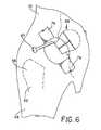
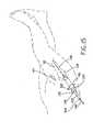
- a custom osteotomy guide 78is placed through anterior incision 44 (Fig. 1) and functions to guide the femoral neck cut. Alignment portion 82 of osteotomy guide 78 is aligned with the longitudinal axis of femur 62, while cut guide 84 is positioned on femoral neck 60. Handle 80 of osteotomy guide 78 facilitates positioning and repositioning of osteotomy guide 78 through anterior incision 44. After placement of osteotomy guide 78, cut line 85 is scored as is known in the art. Osteotomy guide 78 is thereafter removed through anterior incision 44 and femoral cutting tool 86 is inserted through anterior incision 44 and utilized to cut along cut line 85 and displace portion 88 (Fig. 6) from femur 62.
- Retractors 76are repositioned around the anterior and posterior rims of the acetabulum.
- a custom curved cutting tooli . e ., the "ligamentum teres cutter”
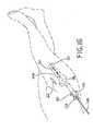
- femoral head 56is passed behind femoral head 56 to sharply incise the ligamentum teres, thus mobilizing cut portion 88 as illustrated in Fig. 6.
- Cut portion 88includes femoral head 56 as well as a portion of femoral neck 60 (Fig. 4). Cut portion 88 is thereafter removed through anterior incision 44 with a custom femoral head bone grasper 94 (Fig. 7). If there is difficulty removing cut portion 88 in one piece, it may be in situ morselized using cutting tool 87 (Fig.
- Morsels 92may then be removed through anterior incision 44. Morselizing of cut portion 88 is accomplished making cuts which substantially mirror the cuts in hip capsule 74. Irrigation and suction devices can be used to cool the bone and facilitate the removal of bony debris in hip capsule 74. In one exemplary embodiment, a fiberoptic endoscope is placed into the hip joint to confirm the complete removal of bony debris.
- fibro-fatty tissue within the cotyloid fossa of acetabulum 54is removed with the use of, e.g., a high-speed acorn-tipped cutting tool 96, Rongeur forceps, and a curette. Thereafter, the acetabular labrum is trimmed with a scalpel. As illustrated in Fig. 8B, acetabulum 54 is then progressively reamed with standard acetabular reamer 98. Acetabular reamers within a predetermined size range are utilized until the optimal size of the acetabulum is reached. Sizing of the acetabulum is facilitated by the use of pre-operative templates and radiographs as is known in the art.
- an endoscopecan be used to aid in visualization during the reaming process.
- the acetabulumis under reamed by approximately 2mm with respect to the diameter of the anticipated acetabular cup so as to create an interference fit.
- High speed acorn-shaped cutting tool 96, and acetabular reamer 98enter the body through anterior incision 44.
- a press-fit acetabular cup of the appropriate sizeis firmly seated with a standard cup inserter 100 as illustrated in Fig. 9 and impacted into the acetabular recess as is known in the art.
- Proper positioning of the acetabular cupis achieved with a custom anteflexion and pelvic alignment guide.
- Patient 40is placed in supine position on operating table 102.
- Aligning rod 104is aligned with the mid lateral axis of torso 52 while main shaft 105 is maintained approximately 30° from operating table 102 for proper seating of the acetabular cup.
- a flexible drillcan be used to guide the placement of one or more acetabular screws.
- acetabular linerThe insertion of the acetabular liner is deferred until the proximal femur has been prepared for the insertion of a trial stem.
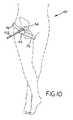
- patient 40As illustrated by the anterior elevational view of Fig. 10, patient 40 remains in the supine position on operating table 102 (Fig. 9) while cup inserter 100 is utilized to seat the acetabular cup.
- the patientFor preparation of the femur, the patient is repositioned with a pad placed under the ipsilateral hip. The hip is slightly flexed, adducted approximately 30°, and maximally externally rotated.
- Retractors 76are repositioned around the medial and lateral aspects of femur 62.
- a self-retaining retractor with a light source attachment and an endoscope holdercan be positioned in anterior incision 44 to provide constant visualization and illumination of femur 62.
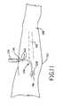
- a scalpel or curved osteotomeWith a scalpel or curved osteotome, the soft tissues along the anterior surface of femur 62 just inferior to the intertrochanteric ridge are subperiosteally reflected to expose the bone for a width of approximately 1 cm. This sharp subperiosteal elevation continues superolaterally onto the anterior margin of the greater trochanter. Then with curved Mayo scissors a pathway is developed by blunt dissection that is directed superficially to the anterior fibers of the gluteus minimus towards buttock 50 (Fig. 11).
- awl 106is inserted through the anterior incision 44, directed superficially to the cleft in the gluteus minimus, and advanced into the soft tissues of buttock 50 until its pointed distal end 108 can be palpated on the surface of the skin.
- Distal end 108 of awl 106is generally aligned with the longitudinal axis of femur 62.
- posterior incision 46of approximately 2.5 - 3.75cm (1 - 1.5 inches) is made and extended through the subcutaneous tissues and fascia lata to expose the underlying gluteus maximus.
- a tract to femur 62is developed along the path created by awl 106.
- elliptical posterior retractor 122includes posterior lip 128 (Fig. 14). In this embodiment, retractor 122 is threaded down to the osteotomized femoral neck until posterior lip 128 lies beneath the posterior intertrochanteric ridge.
- Figure 14Aillustrates an embodiment of rasp tunnel 130 without posterior lip 128.
- each component of posterior retractor 122i.e., guide tube 124, reamer tunnel 126, and rasp tunnel 130
- each individual tunnelmay be provided with a posterior lip similar to posterior lip 128 illustrated in Figure 14.
- blunt tipped guide wire 146is inserted through guide tube 124 of posterior retractor 122 and advanced into femoral canal 148. While Figure 15 illustrates guide tube 124 nested in reamer tunnel 126 and rasp tunnel 130, guide tube 124 may be directly inserted through posterior incision 46. If the cancellous bone of femur 62 is too dense to permit insertion of blunt tipped guide wire 146, then a conical cannulated reamer or end mill is used to prepare the femoral metaphysis. If a nested posterior retractor configuration is utilized, guide tube 124 must be removed so that the reamer can be inserted through reamer tunnel 126 of posterior retractor 122.
- reamer tunnel 126must be inserted into posterior incision 46.
- blunt tipped guide wire 146is inserted about halfway down femoral canal 148.
- the following detailed description of the inventionmakes reference to a nested posterior retractor configuration. It will be understood by those skilled in the art that if the nested configuration is not utilized, each individual component of posterior retractor 122 will be inserted and removed through posterior incision 46 as necessary.
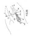
- Fig. 16illustrates preparation of femoral canal 148 to receive rasp 204 (Fig. 19).
- Guide tube 124is removed from posterior retractor 122 and end cutter 150 (Fig. 17A) is inserted through reamer tunnel 126.
- Fig. 18illustrates end cutter 150 positioned within reamer tunnel 126.
- End cutter 150includes elongate aperture 160 through which guide wire 146 passes and guides end cutter 150.
- End cutter 150is actuated by any of the many actuating devices known in the art. After end cutting is complete, end cutter 150 is removed through reamer tunnel 126 and reamer 151 (Fig. 17B) is inserted therethrough.
- Reamer 151includes reamer guide aperture 161 through which guide wire 146 passes and guides reamer 151 as it reams femoral canal 148. Reamers of progressive increase in their outer diameter are sequentially placed over guide wire 146 and femoral canal 148 is reamed until cortical "chatter" is felt. As is known in the art, the optimal diameter of femoral canal 148 is provisionally determined by preoperative templating. Some surgeons may choose to avoid reaming of the femoral shaft and instead utilize a broach as is known in the art. A broach may be inserted in accordance with the current invention as described hereinbelow with respect to rasp insertion.
- reamer tunnel 126(Fig. 14) is removed from posterior retractor 122 so that rasp 204 and rasp handle 212 (Fig. 19) can be inserted over guide wire 146 to complete preparation of femur 62.
- Guide wire 146is inserted into rasp guide aperture 214 and rasp handle guide aperture 202 to guide rasp 204 to prepared femur 62.
- Impact surface 164is struck, as is known in the art, to place rasp 204 in femur 62.
- the rotational alignmentcan be assessed by direct visual scrutiny of femur 62 through anterior incision 44.
- assessment of the alignment of rasp handle 212 with respect to the patella, lower leg, and footfacilitates alignment.
- rasp handle 212is removed along with guide wire 146 and posterior retractor 122, leaving distal end 208 of flexible cable 192 (Fig. 19A) attached to the proximal end of rasp 204 and proximal end 194 of flexible cable 192 protruding from posterior incision 46.
- the operation of rasp handle 212will be further explained below.
- a trial acetabular lineris placed through anterior incision 44 and into the seated acetabular cup with the use of a liner inserter as is known in the art.
- Provisional neck 222is inserted through anterior incision 44 and locked to the top end of the seated rasp, as illustrated in Fig. 22.
- a trial femoral headis placed on the Morse taper of provisional neck 222 through anterior incision 44.
- the hip jointis reduced for an assessment of stability of the hip joint and limb length. Where necessary, a second assessment is made. Once the trial reduction is satisfactorily completed, the hip is dislocated and the provisional head and provisional neck 222 are removed.
- Rasp handle 212is reinserted through posterior incision 46 over the free end of flexible cable 192. Rasp handle 212 is advanced until it can be locked with the seated rasp so that impact surface 164 can be impacted and the entire tool (i.e., rasp 204 and rasp handle 212) can be removed. The trial acetabular liner is removed through anterior incision 44.
- acetabular liner 252(Fig. 30) is seated into acetabular cup 250 (Fig. 30) with a liner inserter that permits its impaction in place, as is known in the art.
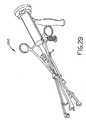
- Femoral implant 238(Fig. 30) is anchored to femoral stem insertion tool 240 (Fig. 29) and placed through posterior incision 46.
- femoral implant 238is placed in protective, disposable bag 242 prior to its introduction into posterior incision 46.
- Protective, disposable bag 242keeps femoral implant 238 clean as it is inserted through posterior incision 46.
- Fig. 25illustrates femoral implant 238 oriented as it will be when placed in femur 62.
- femoral implant 238To insert femoral implant 238 through posterior incision 46, femoral implant 238 must be rotated 180° from this position to prevent impingement on the body. Femoral implant 238 is then rotated 180° after being completely inserted through posterior incision 46.
- Fig. 26illustrates femoral stem 238 and bag 242 inserted through posterior incision 46.
- the tip of femoral stem 238approaches the osteotomized femoral neck, the distal end of bag 242 is incised as illustrated in Fig. 27.
- Scalpel 246is inserted into anterior incision 44 to incise bag 242.
- bag 242is progressively removed through posterior incision 46 as illustrated in Fig. 28.
- femoral stem insertion tool 240(Fig. 29) is removed through posterior incision 46.
- anterior incision 44the final femoral head is positioned on the femoral neck Morse taper using a standard holding device and secured with a standard impaction tool and mallet. The hip is then reduced and assessed for stability.
- a suitable local anesthetic solutionis injected into the closed hip joint as well as the capsular layer and the subcutaneous tissues, allowing superior postoperative pain relief.
- the fascial layers, subcutaneous tissues, and skin of both anterior and posterior woundsare closed in a conventional method and dressings are applied.
- a suction drainmay be used at the discretion of the surgeon.
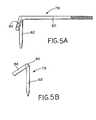
- Osteotomy guide 78illustrated in use in Fig. 4, includes handle 80, alignment portion 82, and cut guide 84.
- cut guide 84 and alignment portion 82form a 60° angle.
- alignment portion 82includes a tapered distal end as illustrated in Figs. 5A and 5B.
- Osteotomy guide 78is inserted through anterior incision 44 and is positioned with alignment portion 82 being placed on femur 62 so that alignment portion 82 generally aligns with the longitudinal axis of femur 62.
- Handle 80protrudes through anterior incision 44 and may be utilized to position osteotomy guide 78.
- osteotomy guide 78is utilized to mark cut line 85 on femoral neck 60 as illustrated in Fig. 4.
- Osteotomy guide 78can be formed to function on either side of the body.
- Fig. 4illustrates an osteotomy guide designed to function on the right femur; while
- Fig. 5Billustrates an osteotomy guide operable to function on the left femur.
- awl 106(Fig. 12) is designed for insertion through anterior incision 44 to locate posterior incision 46 (Fig. 11).
- Awl shaft 116includes proximal end 110 designed for insertion into handle 112.
- Handle 112includes a longitudinal channel 120 into which proximal end 110 of awl shaft 116 may be inserted.
- Locking screw 118is operably positioned in handle 112 and may be actuated by locking knob 114. Locking knob 114 is utilized to place locking screw 118 in locking engagement with proximal end 110 of awl 106.
- proximal end 110 of awl 106includes a flat portion to engage locking screw 118 and facilitate the locking engagement of awl shaft 116 to handle 112.
- Awl shaft 116further includes distal end 108.
- Distal end 108is generally straight and is utilized to generally align with a longitudinal axis of femur 62 (Fig. 11).
- distal end 108 of awl shaft 116includes a tapered end to facilitate insertion of awl 106 through anterior incision 44 to locate posterior incision 46.
- distal end 108 of awl 106may be of smaller diameter than the body of awl shaft 116 as illustrated in Fig. 12.
- awl 106is formed in one piece and is disposable.
- posterior retractor 122comprises three nested parts.
- Guide tube 124is nested in reamer tunnel 126 while reamer tunnel 126 is nested in rasp tunnel 130.
- guide tube 124, reamer tunnel 126, and rasp tunnel 130can be nested together to form a single unit.
- Rasp tunnel 130includes exterior threads 132 to facilitate threading of posterior retractor 122 through posterior incision 46.
- Rasp tunnel 130includes rasp aperture 134 through which reamer tunnel 126 may be inserted and, in one alternative embodiment, posterior lip 128 for positioning posterior retractor 122, as discussed above.
- Reamer tunnel 126includes flange 136 which is operable to retain the position of reamer tunnel 126 within rasp tunnel 130.
- Reamer tunnel 126includes reamer aperture 138 through which guide tube 124 may be inserted.
- Guide tube 124includes a tapered distal end 140 to facilitate its insertion into reamer aperture 138.
- Guide tube 124includes guide wire aperture 144 through which guide wire 146 (Fig. 15) may be inserted.
- Reamer aperture 138is sized to allow insertion of end cutter 150 (Fig. 18), or femoral reamer 151 as discussed above. As illustrated in Fig. 18, guide tube 124 is removed from reamer tunnel 126 and end cutter 150 is inserted through reamer aperture 138.
- Longitudinal reamer aperture 138is sized to accommodate guide cylinders 156 and to thereby provide guidance and stability to end cutter 150.
- reamer tunnel 126is removed from rasp tunnel 130.
- Rasp aperture 134is sized to accommodate insertion of rasp 204 as well as cannular insertion member 168 of rasp handle 212.
- the posterior retractorcan comprise a rasp tunnel with a guide tube nested therein and not include a reamer tunnel as described above.
- posterior retractor 122is not always utilized in its nested configuration.
- guide tube 124, reamer tunnel 126, and rasp tunnel 130are each inserted into and removed from posterior incision 46 as necessary.
- rasp handle 212includes cannular insertion member 168, impact surface 164, grip 166, elongate guide aperture 202, elongate aperture 200, and engagement channel 190.
- Rasp 204includes an aperture 216 sized to receive and retain retainer 210 on distal end 208 of flexible cable 192.
- Retainer 210is placed in aperture 216 and flexible cable 192 follows cable channel 217 to exit rasp 204.
- Proximal end 194 of flexible cable 192is inserted through elongate aperture 200 of cannular insertion member 168 and distal rasp engagement guide 206 is piloted to guide channel 215 of rasp 204.
- proximal end 194 of flexible cable 192may be received in engagement channel 190.
- Engagement channel 190is sized to accommodate and retain retainer 196. After retainer 196 is operably positioned in engagement channel 190, grip 166 may be actuated to tension flexible cable 192.
- retainer 196is operably positioned in engagement channel 190.
- Attaching means 184such as, e.g., rivets, belts, etc. are utilized to affix biasing elements 172 to grip 166 and internal handle surface 182.
- Grip 166is outwardly biased by handle biasing elements 172 and pivots about pivot point 198.
- Grip 166includes tensioning member 188 and ratchet 174.
- Ratchet 174is designed for engagement with tapered end 186 of pawl 176.
- Pawl 176includes pawl flange 178.
- Spring 180engages internal handle surface 82 and pawl flange 178 to bias pawl 176 toward cannular insertion member 168.
- FIG. 20Aillustrates grip 166 retained by pawl 176 in the closed position. As illustrated, tensioning member 188 contacts and tensions flexible cable 192, thus locking rasp 204 to rasp handle 212. Lock disengagement knob 170 can be pulled against the biasing force of spring 180 to unlock grip 166.
- provisional neck 222can be locked to rasp 204 utilizing forceps 220.
- Forceps 220include blade ends 230, 232.
- Blade ends 230, 232are sized for insertion into provisional head apertures 234, 236, respectively (Figs. 24B and 24C).
- provisional neck 222includes locking cylinder 224 and spring 228.
- Spring 228upwardly biases locking cylinder 224.
- blade ends 230, 232can contact tapered portion 226 of locking cylinder 224. Actuation of blade ends 230, 232 against tapered portion 226 causes locking piston 224 to move in a direction opposite to the biasing force of spring 228.
- Provisional neck 222is clamped to forceps 220 and slid in a radial direction into provisional neck engagement area 218 (Figs. 21 and 21A) on rasp 204. After provisional neck 222 is fully slid onto rasp 204, forceps 220 may be released, thereby allowing locking piston 224 to return to its locked position under the biasing force of spring 228. Rasp 204 includes circular cut outs 217 which can be engaged by locking cylinder 224 to lock provisional neck 222 in place.
- Channels 225 (Fig. 24A) on provisional neck 222accommodate protrusions 219 (Fig. 21) on rasp 204.
- Provisional neck 222is slid onto rasp 204 with protrusions 219 occupying channels 225 of provisional neck 222.
- Stop 223 of provisional neck 222abuts protrusions 219 when provisional neck 222 is completely slid onto rasp 204.
- locking cylinder 224may be locked ( i.e ., forcep blades 230, 232 released) so that locking cylinder 224 engages circular cut outs 217, locking provisional neck 222 to rasp 204.
- the method of the current inventionhas been described with reference to a particular hip prosthesis, this is not meant to be limiting in any way and it will be understood that the method of the current invention could be used with many prosthetics, including, e . g ., a cementless prosthesis, a hybrid prosthesis having a cemented stem and a cementless acetabular cup, a cemented prosthesis having both a cemented stem and a cemented acetabular cup, or an Endo prosthesis for replacing only the femoral head.
- the bone cementwill generally be inserted through the anterior incision. It should also be understood by those skilled in the art that in a smaller patient the method of the current invention could be performed entirely through the anterior incision with no need to make a posterior incision as described above.
Landscapes
- Health & Medical Sciences (AREA)
- Life Sciences & Earth Sciences (AREA)
- Engineering & Computer Science (AREA)
- Surgery (AREA)
- Biomedical Technology (AREA)
- Veterinary Medicine (AREA)
- Public Health (AREA)
- General Health & Medical Sciences (AREA)
- Animal Behavior & Ethology (AREA)
- Heart & Thoracic Surgery (AREA)
- Orthopedic Medicine & Surgery (AREA)
- Molecular Biology (AREA)
- Medical Informatics (AREA)
- Oral & Maxillofacial Surgery (AREA)
- Nuclear Medicine, Radiotherapy & Molecular Imaging (AREA)
- Dentistry (AREA)
- Transplantation (AREA)
- Mechanical Engineering (AREA)
- Physical Education & Sports Medicine (AREA)
- Vascular Medicine (AREA)
- Cardiology (AREA)
- General Engineering & Computer Science (AREA)
- Wood Science & Technology (AREA)
- Forests & Forestry (AREA)
- Pathology (AREA)
- Surgical Instruments (AREA)
- Prostheses (AREA)
Abstract

Description
- The present invention relates to total hip arthroplasty, and, more particularly, to a method and apparatus for performing a minimally invasive total hip arthroplasty.
- Orthopaedic procedures for the replacement of all, or a portion of, a patient's joint have been developed over the last 30 years. Currently, the procedures used to prepare the bone and seat the implants are generally referred to as open procedures. For the purpose of this discussion, the term open procedure will refer to a procedure wherein an incision is made through the skin and underlying tissue to fully expose a large portion of the particular joint surface. In the case of a total hip arthroplasty, the typical incision required is approximately 25 centimeters (10 inches) long. After the initial incision in the skin, the internal wound may be enlarged in order to fully expose the areas to be prepared. While this approach provides surgeons with an excellent view of the bone surface, the underlying damage to the soft tissue, including the muscles, can lengthen a patient's rehabilitation time after surgery. While the implants may be well fixed at the time of surgery, it may be several weeks or perhaps months before the soft tissues violated during surgery can be fully healed.
- The present invention provides an improved method and apparatus for performing a minimally invasive total hip arthroplasty. A total hip arthroplasty can be performed in accordance with the teachings of the current invention utilizing two incisions with the size of each of the wounds developed on the surface being substantially constant throughout the depth of the wound. The first incision is an anterior incision approximately 3.75-5 centimeters (1.5 - 2 inches) in length made in line with the femoral neck and the central axis of the acetabulum. The second incision is a posterior incision approximately 2.5-3.75 centimeters (1-1.5 inches) positioned to be generally in axial alignment with the femoral shaft.
- The femoral head is severed from the femoral shaft and removed through the anterior incision. The acetabular cup is placed in the acetabulum through the anterior incision, while the posterior incision is used to prepare the femoral shaft to receive a femoral stem. A femoral stem is inserted through the posterior incision and positioned in the femoral shaft. Procedures performed through the posterior incision may be observed through the anterior incision and vice versa.
- For the purpose of the following discussion, a total hip arthroplasty is defined as a replacement of the femoral head with or without the use of a separate acetabular component. The specific designs which can be utilized in accordance with the present invention include a total hip replacement and a bipolar or monopolar endo prosthesis. The technique is suitable for cemented or cementless anchorage of the components.
- The invention, in one form thereof, comprises a method of performing a total hip arthroplasty. The method of this form of the current invention includes the steps of: making an anterior incision, making a posterior incision, preparing an acetabulum to receive an acetabular cup through the anterior incision, seating an acetabular cup in said acetabulum through the anterior incision, preparing a femur to receive a femoral stem, and seating the femoral stem in the femur.
- The invention, in another form thereof, comprises a method of performing a total hip arthroplasty. The method of this form of the current invention includes the steps of: preparing a femur to receive a femoral stem, placing a protective bag over the femoral stem, and seating the femoral stem in the femur.
- The invention, in another form thereof, comprises a method of performing a total hip arthroplasty. The method of this form of the current invention includes the steps of: placing the patient in supine position; palpating the femoral neck and making an anterior incision of about 3.75 - 5 centimeters (1.5 - 2 inches) in line with the femoral neck and the central axis of the acetabulum; performing a blunt dissection of the muscle exposed by the anterior incision to expose the capsule of the hip joint; incising the capsule of the hip joint; retracting a portion of the capsule to visually expose the femoral neck; utilizing an osteotomy guide to mark a cut path along which a cut will be made to remove the femoral head and a portion of the femoral neck; cutting along the cut path; incising the ligamentum teres femoris; in situ morselizing the cut away femoral head and neck as necessary for removal through the anterior incision; removing the morsels of the femoral neck and head through the anterior incision; reaming the acetabulum; seating the appropriate acetabular cup in the reamed acetabulum; inserting a curved awl having a substantially straight distal end into the anterior incision; aligning the distal end of the awl with the femoral axis; palpating the distal end of the awl and making a posterior incision having a length of about 2.5 - 3.75 centimeters (1 - 1.5 inches) at the location of the distal end of the awl; performing a blunt dissection to provide an access through the posterior incision to the femoral shaft; threading a retractor into the recess formed between the posterior incision and the femoral shaft; passing a guide wire through the retractor and into the cancellous bone of the femoral shaft; positioning the guide wire in the cannula of a femoral reamer; reaming the femoral shaft with the femoral reamer using the guide wire to locate the cancellous bone of the femur; observing the reaming activity through the anterior incision; removing the femoral reamer; utilizing the guide wire to guide a rasp to the femoral shaft; positioning the rasp in the femoral shaft while observing through the anterior incision; removing the guide wire; removing the retractor from the posterior incision; positioning a trial acetabular liner in the acetabular cup through the anterior incision; affixing a provisional neck to the rasp through the anterior incision; affixing a provisional head to the provisional neck through the anterior incision; performing a trial reduction with the trial acetabular liner, provisional neck and provisional head in place; dislocating the provisional head; removing the trial acetabular liner through the anterior incision; removing the provisional neck and head through the anterior incision; removing the rasp through the posterior incision; seating a final acetabular liner in the acetabular cup through the anterior incision; inserting a femoral implant through the posterior incision; inserting a final femoral head through the anterior incision; affixing the final femoral head to the femoral implant; reducing the hip; and closing the incisions.
- In one form of the current invention, the step of positioning a rasp in the femoral shaft comprises: locking the rasp to a rasp handle having a cannular insertion member with a distal rasp engagement guide and an elongate aperture sized to accommodate a flexible cable, an engagement slot for selectively engaging an end of the flexible cable, a selectively actuatable grip operable to tension the flexible cable, a lock for selectively locking the grip in a position to tension the flexible cable, and an impact surface for receiving blows to place or remove the rasp; positioning the guide wire in a cannula of the rasp and the cannula of the rasp handle; guiding the rasp and the cannular insertion member through the posterior retractor to a proximal end of the femoral shaft using the guide wire; striking the impact surface to position the rasp within the femoral shaft; unlocking the grip; releasing the flexible cable from the engagement slot; and removing the rasp handle.
- In one form of the current invention, the step of locking the rasp to a rasp handle comprises: engaging a distal end of the flexible cable in the rasp; inserting the flexible cable through the elongate aperture of the rasp handle; guiding the distal rasp engagement guide into a rasp engagement guide receiving portion on the rasp; engaging the proximal end of the flexible cable in the engagement slot; and tensioning the flexible cable.
- In one form of the current invention, the step of removing the rasp from the femoral shaft comprises: reinserting the flexible cable through the elongate aperture of the cannular insertion member (the flexible cable remains engaged with the rasp placed in the femur and protrudes from the posterior wound); reinserting the cannular insertion member through the posterior retractor; guiding the distal rasp engagement guide into the rasp engagement receiving portion on the rasp; engaging the proximal end of the flexible cable in the engagement slot; tensioning the flexible cable; and impacting the impact surface to remove the rasp from the femoral shaft.
- The invention, in another form thereof, comprises a method of removing a femoral neck and head. The method of this form of the current invention includes the steps of: making an anterior incision in line with the femoral neck; providing an osteotomy guide having a handle and with an alignment portion and a cut guide affixed to the handle; aligning the alignment portion with the femoral axis, marking a cut path defined by the cut guide, and cutting along the cut path to remove a cut portion comprising a portion of the femoral neck and the femoral head.
- The invention, in another form thereof, comprises a method of making a posterior incision aligned with a longitudinal axis of the femur. The method of this form of the current invention includes the steps of making an anterior incision aligned with the femoral neck, providing an awl having a handle and a curved awl shaft having a distal end, aligning the distal end with the longitudinal axis of the femur, palpating a location of the distal end of the awl, and making a posterior incision at the location of the distal end of the awl.
- The invention, in another form thereof, comprises a method of preparing a femur to receive a femoral implant. The method of this form of the current invention includes the steps of: removing the femoral head and neck as necessary, making a posterior incision of approximately 2.5 - 3.75cm which is substantially aligned with the central axis of the femoral shaft, performing a blunt dissection to provide an access through the posterior incision to expose the femoral shaft, inserting a retractor comprising a tunnel sized for insertion through the access into the access, and preparing the femur to receive a femoral implant through the retractor.
- The invention, in another form thereof, comprises an osteotomy guide having a handle allowing use of the osteotomy guide a distance from a femur as well as an alignment portion and a cut guide affixed to the handle.
- The invention, in another form thereof, comprises an awl having a handle and an awl shaft with a distal end. The distal end of the awl shaft is adapted to be inserted into an anterior incision and aligned with the longitudinal axis of a femur to locate a posterior incision operable to expose a proximal end of the femur.
- The invention, in another form thereof, comprises a retractor formed of a tunnel sized for insertion through an access leading to the femoral shaft in a body.
- The invention, in another form thereof, comprises a rasp handle having an insertion member with engagement means for selectively engaging a cable which is affixable to a rasp. In one form of the current invention, the engagement means comprises an engagement slot for selectively engaging the cable.
- The invention, in another form thereof, comprises a provisional femoral neck apparatus including a provisional femoral neck having a hollow, substantially cylidrical body. A spring biased locking piston is provided and housed within said hollow cylindrical body. The locking piston includes a tapered body portion. Application of a radial force to the tapered body portion moves the locking piston against the biasing force of the spring. The blades of a forceps may be utilized to apply the radial force to the tapered portion of the locking piston.
- The invention, in another form thereof, comprises a provisional prosthetic femoral neck having a guide surface and a provisional femoral stem including a mate to the guide surface. The guide surface is piloted to the mate to join the femoral neck and the femoral stem. In one form of the current invention, the femoral neck is substantially cylindrical and is piloted to the femoral stem in a radial direction.
- The apparatus and method of the current invention advantageously allow a total hip arthroplasty to be performed in a minimally invasive way, which hastens patient recovery.
- The above-mentioned and other features and advantages of this invention, and the manner of attaining them, will become more apparent and the invention itself will be better understood by reference to the following description of an embodiment of the invention taken in conjunction with the accompanying drawings, wherein:
- Fig. 1 is a side elevational view of a patient illustrating a pair of incisions made according to the current invention as well as the incision utilized in prior art procedures;
- Fig. 2 is an anterior elevational view of a hip joint illustrating the femoral neck axis;
- Fig. 2A is an anterior elevational view illustrating the capsule of the hip joint;
- Fig. 3 is an anterior elevational view of the femoral neck exposed by incising the hip capsule;
- Fig. 4 is an anterior elevational view of the femoral neck with an osteotomy guide of one form of the current invention operably positioned to designate a cut line thereon;
- Fig. 5A is a side elevational view of an alternative embodiment of an osteotomy guide in accordance with the present invention;
- Fig. 5B is an elevational view thereof taken along the longitudinal axis of the handle;
- Fig. 6 is an anterior elevational view illustrating the femoral head and neck severed along the cut line indicated by the osteotomy guide;
- Fig. 7 is an anterior elevational view illustrating the removal of a portion of the femoral head and neck;
- Figs. 8A and 8B illustrate preparation of the acetabulum to receive the acetabular cup;
- Fig. 9 is a side elevational view of an acetabular cup inserter relative to a patient lying in the supine position;
- Fig. 10 is an anterior elevational view of a portion of the cup inserter illustrated in Fig. 9 and a patient lying in the supine position;
- Fig. 11 is a side elevational view illustrating the use of a curved awl to locate a posterior incision;
- Fig. 12 is a side elevational, partial sectional view of an awl in accordance with the present invention;
- Fig. 13 is a perspective view illustrating the insertion of a posterior retractor in the posterior incision;
- Fig. 14 is a perspective, exploded view of one embodiment of a tubular retractor in accordance with the present invention;
- Fig. 14A is a side elevational view of an alternative embodiment of the tubular retractor;
- Fig. 15 is a perspective view illustrating the insertion of a guide wire into the tubular retractor;
- Fig. 16 is a perspective view illustrating reaming of the femoral shaft;
- Fig. 17A is a perspective view of an end cutter;
- Fig. 17B is a perspective view of a femoral reamer;
- Fig. 18 is a side elevational, partial sectional view of an end cutter inserted into a tubular retractor of the present invention;
- Fig. 19 is a perspective view of a rasp handle after inserting a rasp into the femoral shaft;
- Fig. 19A is a perspective view illustrating an inserted rasp, with the rasp handle removed, and with the cable used to affix the rasp to the rasp handle protruding from the posterior incision;
- Figs. 20A and 20B are partial sectional views of the rasp handle;
- Fig. 21 is an exploded view of the rasp handle and a rasp to be connected thereto;
- Fig. 21A is a partial elevational view along
line 21A-21A of Fig. 21; - Fig. 22 is a perspective view illustrating placement of a provisional neck of the present invention;
- Fig. 23 is a perspective view of the provisional neck and mating forceps of the present invention;
- Fig. 24A is a partial sectional, radial elevational view of the provisional neck;
- Figs. 24B and 24C are radial elevational views thereof;
- Fig. 25 is a perspective view illustrating the insertion of a femoral stem with a protective bag through the posterior incision;
- Fig. 26 is a perspective view illustrating alignment of the femoral stem while observing through the anterior incision;
- Fig. 27 illustrates an incision into the femoral stem protective bag prior to insertion of the femoral stem into the femoral shaft;
- Fig. 28 is a perspective view illustrating removal of the femoral stem protective bag while inserting the femoral stem, with observation through the anterior incision;
- Fig. 29 is a perspective view of a femoral stem insertion tool in accordance with the teachings of the present invention; and
- Fig. 30 is a perspective view of a hip prosthesis which can be implanted according to the method of the current invention.
- Corresponding reference characters indicate corresponding parts throughout the several views. The exemplification set out herein illustrates one preferred embodiment of the invention, in one form, and such exemplification is not to be construed as limiting the scope of the invention in any manner.
- A total hip arthroplasty can be performed, according to the teachings of the current invention through two incisions, each no more than 5 centimeters (2 inches) in length. An anterior incision is made along the axis of the femoral neck, while a posterior incision is made generally in axial alignment with the femoral shaft. Referring to Fig. 1, a partial illustration of a patient 40 including
torso 52,buttock 50, andleg 48 illustratesprior art incision 42 as well asanterior incision 44 andposterior incision 46 of the current invention.Prior art incision 42 is approximately 25 centimeters (10 inches) long, whileanterior incision 44 andposterior incision 46 are each no more than 5 centimeters (2 inches) in length. - According to the method of total hip arthroplasty of the current invention,
patient 40 is initially placed in a supine position on a conventional operating table. Referring now to Fig. 2, withleg 48 in a neutral position, two prominent bony landmarks are palpated, the anterior-superior iliac spine (ASIS) 59 and thegreater trochanter 58 offemur 62.Ilium 64 andpubis 66 ofhip 68 are shown to better illustrate the relevant area of the body. The approximate anterior incision starting point 71 is identified two fingerbreadths inferior and two fingerbreadths anterior to the tuberical of thegreater trochanter 58. The approximate finish point for the anterior incision is identified three fingerbreadths inferior and two fingerbreadths lateral to the anterior superior iliac spine (ASIS) 59. With the use of a spinal needle, the appropriate starting point 71 and the path of the anterior incision are identified by impaling the skin down to bone to confirm thecentral axis 70 offemoral neck 60. - An oblique incision of approximately 3.75 - 5 centimeters (1.5 - 2 inches) is made from the starting site 71 toward the prominence of the greater trochanter along the
axis 70 of thefemoral neck 60 and the central axis ofacetabulum 54. The incision is extended along the same plane through subcutaneous tissues, exposing the underlying fascia lata. The internervous plane between the tensor fascia lata muscle and the sartorius is identified by palpation and developed by curved scissors and blunt dissection. The sartorius can be made more prominent by externally rotating the leg to apply tension on the muscle. Deep to the tensor fascia lata and the sartorius is an internervous interval between the rectus femoris and the gluteus medius. This plane is developed by blunt dissection. A lateral retraction of the tensor fascia lata permits a visualization of thecapsule 74 of the hip joint as illustrated in Fig. 2A. Leg 48 is externally rotated to create tension oncapsule 74.Capsule 74 is incised along the axis 70 (Fig. 2) offemoral neck 60 from the equator offemoral head 56 to the intertrochanteric ridge on thefemur 62. The capsular incision takes the form of an "H-shaped" window formed byincisions 72. The H-shaped window is formed by adding supplementary perpendicular limbs around the equator of thefemoral head 56 and the base of thefemoral neck 60 to the initial incision along theaxis 70 offemoral neck 60. As a form of retraction, heavy sutures are used to provisionally attach the capsular flaps 73 to the subcutaneous tissues. As illustrated in Fig. 3,retractors 76 are placed inside capsular flaps 73 and underneath the superior and inferior borders offemoral neck 60 to expose the entire length offemoral neck 60 from the inferior aspect offemoral head 56 to the intertrochanteric ridge. In one exemplary embodiment, each retractor houses a light source and can also serve to anchor an endoscope. Theretractors 76 thereby provide continuous visualization and illumination of the wound.- Referring now to Fig. 4, a
femoral cutting tool 86, e.g., an oscillating saw or a power burr is used to excisefemoral neck 60. Acustom osteotomy guide 78 is placed through anterior incision 44 (Fig. 1) and functions to guide the femoral neck cut.Alignment portion 82 ofosteotomy guide 78 is aligned with the longitudinal axis offemur 62, while cut guide 84 is positioned onfemoral neck 60. Handle 80 ofosteotomy guide 78 facilitates positioning and repositioning of osteotomy guide 78 throughanterior incision 44. After placement ofosteotomy guide 78, cutline 85 is scored as is known in the art.Osteotomy guide 78 is thereafter removed throughanterior incision 44 andfemoral cutting tool 86 is inserted throughanterior incision 44 and utilized to cut alongcut line 85 and displace portion 88 (Fig. 6) fromfemur 62. Retractors 76 are repositioned around the anterior and posterior rims of the acetabulum. As is known in the art, a custom curved cutting tool. (i.e., the "ligamentum teres cutter") is passed behindfemoral head 56 to sharply incise the ligamentum teres, thus mobilizingcut portion 88 as illustrated in Fig. 6.Cut portion 88 includesfemoral head 56 as well as a portion of femoral neck 60 (Fig. 4).Cut portion 88 is thereafter removed throughanterior incision 44 with a custom femoral head bone grasper 94 (Fig. 7). If there is difficulty removing cutportion 88 in one piece, it may be in situ morselized using cutting tool 87 (Fig. 6),e.g., a power burr.Morsels 92 may then be removed throughanterior incision 44. Morselizing ofcut portion 88 is accomplished making cuts which substantially mirror the cuts inhip capsule 74. Irrigation and suction devices can be used to cool the bone and facilitate the removal of bony debris inhip capsule 74. In one exemplary embodiment, a fiberoptic endoscope is placed into the hip joint to confirm the complete removal of bony debris.- As illustrated in Fig. 8A, the fibro-fatty tissue within the cotyloid fossa of
acetabulum 54 is removed with the use of,e.g., a high-speed acorn-tippedcutting tool 96, Rongeur forceps, and a curette. Thereafter, the acetabular labrum is trimmed with a scalpel. As illustrated in Fig. 8B,acetabulum 54 is then progressively reamed with standardacetabular reamer 98. Acetabular reamers within a predetermined size range are utilized until the optimal size of the acetabulum is reached. Sizing of the acetabulum is facilitated by the use of pre-operative templates and radiographs as is known in the art. Once again, an endoscope can be used to aid in visualization during the reaming process. Typically the acetabulum is under reamed by approximately 2mm with respect to the diameter of the anticipated acetabular cup so as to create an interference fit. High speed acorn-shapedcutting tool 96, andacetabular reamer 98 enter the body throughanterior incision 44. - After a trial fitting, a press-fit acetabular cup of the appropriate size is firmly seated with a
standard cup inserter 100 as illustrated in Fig. 9 and impacted into the acetabular recess as is known in the art. Proper positioning of the acetabular cup is achieved with a custom anteflexion and pelvic alignment guide.Patient 40 is placed in supine position on operating table 102. Aligningrod 104 is aligned with the mid lateral axis oftorso 52 whilemain shaft 105 is maintained approximately 30° from operating table 102 for proper seating of the acetabular cup. To augment fixation of the cup, a flexible drill can be used to guide the placement of one or more acetabular screws. The insertion of the acetabular liner is deferred until the proximal femur has been prepared for the insertion of a trial stem. As illustrated by the anterior elevational view of Fig. 10,patient 40 remains in the supine position on operating table 102 (Fig. 9) whilecup inserter 100 is utilized to seat the acetabular cup. - For preparation of the femur, the patient is repositioned with a pad placed under the ipsilateral hip. The hip is slightly flexed, adducted approximately 30°, and maximally externally rotated.
Retractors 76 are repositioned around the medial and lateral aspects offemur 62. Alternatively, a self-retaining retractor with a light source attachment and an endoscope holder can be positioned inanterior incision 44 to provide constant visualization and illumination offemur 62. - With a scalpel or curved osteotome, the soft tissues along the anterior surface of
femur 62 just inferior to the intertrochanteric ridge are subperiosteally reflected to expose the bone for a width of approximately 1 cm. This sharp subperiosteal elevation continues superolaterally onto the anterior margin of the greater trochanter. Then with curved Mayo scissors a pathway is developed by blunt dissection that is directed superficially to the anterior fibers of the gluteus minimus towards buttock 50 (Fig. 11). - As illustrated in Fig. 11,
awl 106 is inserted through theanterior incision 44, directed superficially to the cleft in the gluteus minimus, and advanced into the soft tissues ofbuttock 50 until its pointeddistal end 108 can be palpated on the surface of the skin.Distal end 108 ofawl 106 is generally aligned with the longitudinal axis offemur 62. At the point wheredistal end 108 is palpated,posterior incision 46 of approximately 2.5 - 3.75cm (1 - 1.5 inches) is made and extended through the subcutaneous tissues and fascia lata to expose the underlying gluteus maximus. A tract tofemur 62 is developed along the path created byawl 106. The gluteus maximus is split bluntly in line with its fibers with curved Mayo scissors. Into this pathway viaposterior incision 46, customelliptical posterior retractor 122, complete with its inner sleeves, is threaded (Fig. 13) down to the osteotomized femoral neck. In one exemplary embodiment,elliptical posterior retractor 122 includes posterior lip 128 (Fig. 14). In this embodiment,retractor 122 is threaded down to the osteotomized femoral neck untilposterior lip 128 lies beneath the posterior intertrochanteric ridge. Figure 14A illustrates an embodiment ofrasp tunnel 130 withoutposterior lip 128. In an alternative embodiment, each component of posterior retractor 122 (i.e., guidetube 124,reamer tunnel 126, and rasp tunnel 130) is individually inserted and removed as necessary. In an embodiment in which guidetube 124,reamer tunnel 126, andrasp tunnel 130 are individually inserted and removed intoposterior incision 46, each individual tunnel may be provided with a posterior lip similar toposterior lip 128 illustrated in Figure 14. - Referring now to Fig. 15, blunt tipped
guide wire 146 is inserted throughguide tube 124 ofposterior retractor 122 and advanced intofemoral canal 148. While Figure 15 illustratesguide tube 124 nested inreamer tunnel 126 andrasp tunnel 130,guide tube 124 may be directly inserted throughposterior incision 46. If the cancellous bone offemur 62 is too dense to permit insertion of blunt tippedguide wire 146, then a conical cannulated reamer or end mill is used to prepare the femoral metaphysis. If a nested posterior retractor configuration is utilized,guide tube 124 must be removed so that the reamer can be inserted throughreamer tunnel 126 ofposterior retractor 122. Similarly, if a nested configuration is not utilized,reamer tunnel 126 must be inserted intoposterior incision 46. In any event, blunt tippedguide wire 146 is inserted about halfway downfemoral canal 148. The following detailed description of the invention makes reference to a nested posterior retractor configuration. It will be understood by those skilled in the art that if the nested configuration is not utilized, each individual component ofposterior retractor 122 will be inserted and removed throughposterior incision 46 as necessary. - Fig. 16 illustrates preparation of
femoral canal 148 to receive rasp 204 (Fig. 19).Guide tube 124 is removed fromposterior retractor 122 and end cutter 150 (Fig. 17A) is inserted throughreamer tunnel 126. Fig. 18 illustratesend cutter 150 positioned withinreamer tunnel 126.End cutter 150 includeselongate aperture 160 through whichguide wire 146 passes and guidesend cutter 150.End cutter 150 is actuated by any of the many actuating devices known in the art. After end cutting is complete,end cutter 150 is removed throughreamer tunnel 126 and reamer 151 (Fig. 17B) is inserted therethrough.Reamer 151 includes reamer guide aperture 161 through whichguide wire 146 passes and guidesreamer 151 as it reamsfemoral canal 148. Reamers of progressive increase in their outer diameter are sequentially placed overguide wire 146 andfemoral canal 148 is reamed until cortical "chatter" is felt. As is known in the art, the optimal diameter offemoral canal 148 is provisionally determined by preoperative templating. Some surgeons may choose to avoid reaming of the femoral shaft and instead utilize a broach as is known in the art. A broach may be inserted in accordance with the current invention as described hereinbelow with respect to rasp insertion. - After the correct diameter of
femoral canal 148 is reamed out, reamer tunnel 126 (Fig. 14) is removed fromposterior retractor 122 so thatrasp 204 and rasp handle 212 (Fig. 19) can be inserted overguide wire 146 to complete preparation offemur 62.Guide wire 146 is inserted intorasp guide aperture 214 and rasp handleguide aperture 202 to guiderasp 204 toprepared femur 62.Impact surface 164 is struck, as is known in the art, to placerasp 204 infemur 62. Whilerasp 204 is being impacted, the rotational alignment can be assessed by direct visual scrutiny offemur 62 throughanterior incision 44. Furthermore, assessment of the alignment of rasp handle 212 with respect to the patella, lower leg, and foot facilitates alignment. - Progressively larger rasps are inserted to achieve the optimal fit and fill in
femur 62. Once the final rasp is fully seated, rasp handle 212 is removed along withguide wire 146 andposterior retractor 122, leavingdistal end 208 of flexible cable 192 (Fig. 19A) attached to the proximal end ofrasp 204 andproximal end 194 offlexible cable 192 protruding fromposterior incision 46. The operation of rasp handle 212 will be further explained below. - After the final rasp is seated in
femoral canal 148, a trial acetabular liner is placed throughanterior incision 44 and into the seated acetabular cup with the use of a liner inserter as is known in the art.Provisional neck 222 is inserted throughanterior incision 44 and locked to the top end of the seated rasp, as illustrated in Fig. 22. A trial femoral head is placed on the Morse taper ofprovisional neck 222 throughanterior incision 44. The hip joint is reduced for an assessment of stability of the hip joint and limb length. Where necessary, a second assessment is made. Once the trial reduction is satisfactorily completed, the hip is dislocated and the provisional head andprovisional neck 222 are removed. Rasp handle 212 is reinserted throughposterior incision 46 over the free end offlexible cable 192. Rasp handle 212 is advanced until it can be locked with the seated rasp so thatimpact surface 164 can be impacted and the entire tool (i.e.,rasp 204 and rasp handle 212) can be removed. The trial acetabular liner is removed throughanterior incision 44. - Via
anterior incision 44, the final acetabular liner 252 (Fig. 30) is seated into acetabular cup 250 (Fig. 30) with a liner inserter that permits its impaction in place, as is known in the art. Femoral implant 238 (Fig. 30) is anchored to femoral stem insertion tool 240 (Fig. 29) and placed throughposterior incision 46. As illustrated in Fig. 25,femoral implant 238 is placed in protective,disposable bag 242 prior to its introduction intoposterior incision 46. Protective,disposable bag 242 keepsfemoral implant 238 clean as it is inserted throughposterior incision 46. Note that Fig. 25 illustratesfemoral implant 238 oriented as it will be when placed infemur 62. To insertfemoral implant 238 throughposterior incision 46,femoral implant 238 must be rotated 180° from this position to prevent impingement on the body.Femoral implant 238 is then rotated 180° after being completely inserted throughposterior incision 46. - Fig. 26 illustrates
femoral stem 238 andbag 242 inserted throughposterior incision 46. When the tip offemoral stem 238 approaches the osteotomized femoral neck, the distal end ofbag 242 is incised as illustrated in Fig. 27.Scalpel 246 is inserted intoanterior incision 44 to incisebag 242. Asfemoral stem 238 is driven intofemoral canal 148,bag 242 is progressively removed throughposterior incision 46 as illustrated in Fig. 28. Afterfemoral stem 238 is fully seated, femoral stem insertion tool 240 (Fig. 29) is removed throughposterior incision 46. Throughanterior incision 44, the final femoral head is positioned on the femoral neck Morse taper using a standard holding device and secured with a standard impaction tool and mallet. The hip is then reduced and assessed for stability. - After appropriate antibiotic irrigation, the hip capsule and the soft tissues are repaired with heavy sutures or staples: A suitable local anesthetic solution is injected into the closed hip joint as well as the capsular layer and the subcutaneous tissues, allowing superior postoperative pain relief. The fascial layers, subcutaneous tissues, and skin of both anterior and posterior wounds are closed in a conventional method and dressings are applied. A suction drain may be used at the discretion of the surgeon.
Osteotomy guide 78, illustrated in use in Fig. 4, includeshandle 80,alignment portion 82, and cutguide 84. In one exemplary embodiment, cutguide 84 andalignment portion 82 form a 60° angle. In one exemplary embodiment,alignment portion 82 includes a tapered distal end as illustrated in Figs. 5A and 5B.Osteotomy guide 78 is inserted throughanterior incision 44 and is positioned withalignment portion 82 being placed onfemur 62 so thatalignment portion 82 generally aligns with the longitudinal axis offemur 62.Handle 80 protrudes throughanterior incision 44 and may be utilized to positionosteotomy guide 78. After osteotomyguide 78 is properly positioned, cutguide 84 is utilized to mark cutline 85 onfemoral neck 60 as illustrated in Fig. 4.Osteotomy guide 78 can be formed to function on either side of the body. Fig. 4 illustrates an osteotomy guide designed to function on the right femur; while Fig. 5B illustrates an osteotomy guide operable to function on the left femur.- As discussed supra, awl 106 (Fig. 12) is designed for insertion through
anterior incision 44 to locate posterior incision 46 (Fig. 11).Awl shaft 116 includesproximal end 110 designed for insertion intohandle 112. Handle 112 includes alongitudinal channel 120 into whichproximal end 110 ofawl shaft 116 may be inserted. Lockingscrew 118 is operably positioned inhandle 112 and may be actuated by lockingknob 114. Lockingknob 114 is utilized to place lockingscrew 118 in locking engagement withproximal end 110 ofawl 106. In one exemplary embodiment,proximal end 110 ofawl 106 includes a flat portion to engage lockingscrew 118 and facilitate the locking engagement ofawl shaft 116 to handle 112.Awl shaft 116 further includesdistal end 108.Distal end 108 is generally straight and is utilized to generally align with a longitudinal axis of femur 62 (Fig. 11). As illustrated in Fig. 12,distal end 108 ofawl shaft 116 includes a tapered end to facilitate insertion ofawl 106 throughanterior incision 44 to locateposterior incision 46. Additionally,distal end 108 ofawl 106 may be of smaller diameter than the body ofawl shaft 116 as illustrated in Fig. 12. In an alternative embodiment,awl 106 is formed in one piece and is disposable. - Referring now to Fig. 14,
posterior retractor 122 comprises three nested parts.Guide tube 124 is nested inreamer tunnel 126 whilereamer tunnel 126 is nested inrasp tunnel 130. Whenposterior retractor 122 is threaded intoposterior incision 46,guide tube 124,reamer tunnel 126, andrasp tunnel 130 can be nested together to form a single unit.Rasp tunnel 130 includesexterior threads 132 to facilitate threading ofposterior retractor 122 throughposterior incision 46.Rasp tunnel 130 includesrasp aperture 134 through whichreamer tunnel 126 may be inserted and, in one alternative embodiment,posterior lip 128 for positioningposterior retractor 122, as discussed above.Reamer tunnel 126 includesflange 136 which is operable to retain the position ofreamer tunnel 126 withinrasp tunnel 130.Reamer tunnel 126 includesreamer aperture 138 through which guidetube 124 may be inserted.Guide tube 124 includes a tapereddistal end 140 to facilitate its insertion intoreamer aperture 138.Guide tube 124 includesguide wire aperture 144 through which guide wire 146 (Fig. 15) may be inserted.Reamer aperture 138 is sized to allow insertion of end cutter 150 (Fig. 18), orfemoral reamer 151 as discussed above. As illustrated in Fig. 18,guide tube 124 is removed fromreamer tunnel 126 andend cutter 150 is inserted throughreamer aperture 138.Longitudinal reamer aperture 138 is sized to accommodateguide cylinders 156 and to thereby provide guidance and stability to endcutter 150. After end cutting (and reaming, if desired) is complete,reamer tunnel 126 is removed fromrasp tunnel 130.Rasp aperture 134 is sized to accommodate insertion ofrasp 204 as well ascannular insertion member 168 ofrasp handle 212. For surgeries which do not utilize reaming, the posterior retractor can comprise a rasp tunnel with a guide tube nested therein and not include a reamer tunnel as described above. As described above,posterior retractor 122 is not always utilized in its nested configuration. In one exemplary embodiment, guidetube 124,reamer tunnel 126, andrasp tunnel 130 are each inserted into and removed fromposterior incision 46 as necessary. - Referring now to Fig. 21, rasp handle 212 includes
cannular insertion member 168,impact surface 164,grip 166,elongate guide aperture 202,elongate aperture 200, andengagement channel 190.Rasp 204 includes anaperture 216 sized to receive and retainretainer 210 ondistal end 208 offlexible cable 192.Retainer 210 is placed inaperture 216 andflexible cable 192 followscable channel 217 to exitrasp 204.Proximal end 194 offlexible cable 192 is inserted throughelongate aperture 200 ofcannular insertion member 168 and distalrasp engagement guide 206 is piloted to guidechannel 215 ofrasp 204. After exiting the proximal end ofelongate aperture 200,proximal end 194 offlexible cable 192 may be received inengagement channel 190.Engagement channel 190 is sized to accommodate and retainretainer 196. Afterretainer 196 is operably positioned inengagement channel 190,grip 166 may be actuated to tensionflexible cable 192. - Referring now to Fig. 20B,
retainer 196 is operably positioned inengagement channel 190. Attaching means 184, such as, e.g., rivets, belts, etc. are utilized to affix biasingelements 172 to grip 166 and internal handle surface 182.Grip 166 is outwardly biased byhandle biasing elements 172 and pivots aboutpivot point 198.Grip 166 includes tensioningmember 188 and ratchet 174.Ratchet 174 is designed for engagement withtapered end 186 ofpawl 176.Pawl 176 includespawl flange 178.Spring 180 engagesinternal handle surface 82 andpawl flange 178 tobias pawl 176 towardcannular insertion member 168. Actuation ofgrip 166 against the biasing force of biasingelements 172 rotatesgrip 166 aboutpivot point 198, causes ratchet 174 to come into operative engagement withtapered end 186 ofpawl 176, and causes tensioningmember 188 to contactflexible cable 192. Fig. 20A illustratesgrip 166 retained bypawl 176 in the closed position. As illustrated,tensioning member 188 contacts and tensionsflexible cable 192, thus lockingrasp 204 to rasp handle 212.Lock disengagement knob 170 can be pulled against the biasing force ofspring 180 to unlockgrip 166. - Referring now to Fig. 23,
provisional neck 222 can be locked to rasp 204 utilizingforceps 220.Forceps 220 include blade ends 230, 232. Blade ends 230, 232 are sized for insertion intoprovisional head apertures provisional neck 222 includes lockingcylinder 224 andspring 228.Spring 228 upwardlybiases locking cylinder 224. Upon insertion intoapertures portion 226 of lockingcylinder 224. Actuation of blade ends 230, 232 against taperedportion 226causes locking piston 224 to move in a direction opposite to the biasing force ofspring 228.Provisional neck 222 is clamped toforceps 220 and slid in a radial direction into provisional neck engagement area 218 (Figs. 21 and 21A) onrasp 204. Afterprovisional neck 222 is fully slid ontorasp 204,forceps 220 may be released, thereby allowinglocking piston 224 to return to its locked position under the biasing force ofspring 228.Rasp 204 includescircular cut outs 217 which can be engaged by lockingcylinder 224 to lockprovisional neck 222 in place. - Channels 225 (Fig. 24A) on
provisional neck 222 accommodate protrusions 219 (Fig. 21) onrasp 204.Provisional neck 222 is slid ontorasp 204 withprotrusions 219 occupyingchannels 225 ofprovisional neck 222. Stop 223 ofprovisional neck 222 abutsprotrusions 219 whenprovisional neck 222 is completely slid ontorasp 204. When stop 223 abutsprotrusions 219, lockingcylinder 224 may be locked (i.e.,forcep blades cylinder 224 engagescircular cut outs 217, lockingprovisional neck 222 to rasp 204. - While the method of the current invention has been described with reference to a particular hip prosthesis, this is not meant to be limiting in any way and it will be understood that the method of the current invention could be used with many prosthetics, including,e.g., a cementless prosthesis, a hybrid prosthesis having a cemented stem and a cementless acetabular cup, a cemented prosthesis having both a cemented stem and a cemented acetabular cup, or an Endo prosthesis for replacing only the femoral head. In a procedure in which a cemented femoral stem is utilized, the bone cement will generally be inserted through the anterior incision. It should also be understood by those skilled in the art that in a smaller patient the method of the current invention could be performed entirely through the anterior incision with no need to make a posterior incision as described above.
- While this invention has been described as having a preferred design, the present invention can be further modified within the spirit and scope of this disclosure. This application is therefore intended to cover any variations, uses, or adaptations of the invention using its general principles. Further, this application is intended to cover such departures from the present disclosure as come within known or customary practice in the art to which this invention pertains and which fall within the limits of the appended claims.
- Preferred method aspects of the present invention are as follows:
- 1. A method for performing a total hip arthroplasty, comprising:
- making an anterior incision;
- making a posterior incision;
- preparing an acetabulum to receive an acetabular cup through said anterior incision;
- seating an acetabular cup in said acetabulum through said anterior incision;
- preparing a femur to receive a femoral stem; and
- seating said femoral stem in said femur.
- 2. The method of
aspect 1, wherein said anterior incision has a length of about 3.75-5 cm. - 3. The method of
aspect 1, wherein said step of preparing a femur to receive a femoral stem comprises preparing said femur to receive said femoral stem through said posterior incision. - 4. The method of
aspect 1, wherein said step of seating said femoral stem in said femur comprises inserting said femoral stem through said posterior incision and thereafter seating said femoral stem in said femur. - 5. A method of performing a total hip arthroplasty, comprising:
- preparing a femur to receive a femoral stem;
- placing a protective bag over said femoral stem; and
- seating said femoral stem in said femur.
- 6. The method of aspect 5, wherein said step of seating said femoral stem comprises:
- incising the distal end of said protective bag as said femoral stem approaches said femur; and
- progressively pulling said protective bag away from said femoral implant while inserting said femoral implant into said femur.
- 7. A method for performing a total hip arthroplasty, comprising:
- placing a patient in supine position;
- palpating a femoral neck;
- making an anterior incision having a length of about 3.75 to 5 centimeters in line with said femoral neck to expose underlying muscle;
- performing a blunt dissection of said underlying muscle to expose a capsule of a hip joint;
- incising said capsule;
- retracting a portion of said capsule to visually expose said femoral neck;
- providing an osteotomy guide having a handle, an alignment portion affixed to said handle for aligning with a central femoral axis, and a cut guide affixed to said handle;
- aligning said alignment portion with said femoral axis, with said cut guide lying on said femoral neck;
- marking a cut path defined by said cut guide;
- cutting along said cut path to remove a cut portion from a femoral shaft, said cut portion comprising a femoral head and a portion of said femoral neck;
- incising a ligamentum teres femoris;
- in situ morselizing said cut portion as necessary for removal through said anterior incision;
- removing said cut portion through said anterior incision;
- reaming an acetabulum;
- seating an acetabular cup in said acetabulum;
- inserting a curved awl having a substantially straight distal end into said anterior incision;
- aligning said distal end of said awl with said femoral axis;
- palpating a location of said distal end of said awl;
- making a posterior incision having a length of about 2.5 to 3.75 centimeters at said location of said distal end of said awl;
- performing a blunt dissection to provide an access through said posterior incision to expose said femoral shaft;
- inserting a retractor into said access, said retractor comprising:
- a rasp tunnel sized to allow passage of a femoral rasp therethrough;
- a reamer tunnel sized to allow passage of a femoral reamer therethrough, said reamer tunnel nested in said rasp tunnel; and
- a guide tube sized to allow passage of a guide wire therethrough, said guide tube nested in said reamer tunnel;
- passing a guide wire through said guide tube and into the cancellous bone of a femur;
- removing said guide tube from said retractor;
- positioning said guide wire in a cannula of a femoral reamer;
- guiding said femoral reamer to said femoral shaft with said guide wire;
- reaming said femoral shaft with said femoral reamer while observing through said anterior incision;
- removing said reamer tunnel from said retractor;
- positioning a rasp in said femoral shaft using said guide wire to properly position said rasp, while observing through said anterior incision;
- removing said guide wire;
- removing said retractor from said posterior incision;
- positioning a trial acetabular liner in said acetabular cup through said anterior incision;
- affixing a provisional neck to said rasp through said anterior incision;
- affixing a provisional head to said provisional neck through said anterior incision;
- performing a trial reduction with said trial acetabular liner, said provisional neck and said provisional head in place;
- dislocating the provisional head;
- removing said trial acetabular liner through said anterior incision;
- removing said provisional neck and head through said anterior incision;
- removing said rasp through said posterior incision;
- seating a final acetabular liner in said acetabular cup through said anterior incision;
- inserting a femoral implant through said posterior incision;
- inserting a final femoral head through said anterior incision;
- affixing said final femoral head to said femoral implant;
- reducing the hip; and
- closing said incisions.
- 8. The method of aspect 7, wherein said step of palpating a femoral neck comprises palpating an anterior superior iliac spine and a greater trochanter of said femur.
- 9. The method of aspect 7, wherein said step of incising said capsule comprises incising an H-pattern in said capsule.
- 10. The method of aspect 7, wherein said step of retracting a portion of said capsule comprises suturing said portion of said capsule to subcutaneous tissue.
- 11. The method of aspect 7, wherein said rasp tunnel includes a protrusion for aligning said rasp tunnel with said femoral shaft, and wherein said method further comprises aligning said protrusion with said femoral shaft after inserting said retractor into said access.
- 12. The method of aspect 7, wherein said rasp tunnel includes exterior threads, and wherein said step of inserting a retractor into said access comprises threading said retractor into said access.
- 13. The method of aspect 7, wherein said step of positioning a rasp in said femoral shaft comprises:
- locking said rasp to a rasp handle comprising:
- a cannular insertion member, said cannular insertion member having a distal rasp engagement guide, an elongate aperture, and a guide aperture, said elongate aperture sized to accommodate a flexible cable;
- an engagement slot for selectively engaging a proximal end of said flexible cable;
- a selectively actuatable grip operable to tension said flexible cable;
- a lock for selectively locking said grip in a position to tension said flexible cable; and
- an impact surface for receiving blows to place or remove a rasp;
- positioning said guide wire in a guide aperture of said rasp and said guide aperture of said rasp handle;
- guiding said rasp and said cannular insertion member through said rasp tunnel to a proximal end of said femoral shaft using said guide wire;
- impacting said impact surface to position said rasp in said femoral shaft;
- unlocking said grip;
- releasing said flexible cable from said engagement slot of said rasp handle; and
- removing said rasp handle.
- locking said rasp to a rasp handle comprising:
- 14. The method of aspect 13, wherein said step of locking said rasp to a rasp handle comprises:
- engaging a distal end of said flexible cable in said rasp;
- inserting said flexible cable through said elongate aperture of said rasp handle;
- guiding said distal rasp engagement guide into a rasp engagement guide receiving portion on said rasp;
- engaging said proximal end of said flexible cable in said engagement slot of said rasp handle; and
- tensioning said flexible cable.
- 15. The method of aspect 7, wherein said step of affixing a provisional neck to said rasp through said anterior incision comprises:
- unlocking a provisional neck having a lock mechanism;
- inserting said provisional neck into said anterior incision;
- positioning said provisional neck on said rasp; and
- locking said provisional neck to said rasp.
- 16. The method of aspect 14, wherein said step of removing said rasp comprises:
- reinserting said flexible cable through said elongate aperture;
- reinserting said cannular insertion member through said posterior incision;
- guiding said distal rasp engagement guide into said rasp engagement guide receiving portion;
- engaging said proximal end of said flexible cable in said engagement slot;
- tensioning said flexible cable; and
- impacting said impact surface to remove said rasp from said femoral shaft.
- 17. The method of aspect 7, wherein said step of inserting a femoral implant through said posterior incision comprises:
- locking said femoral implant to a femoral stem insertion tool;
- placing said femoral implant and a distal end of said femoral stem insertion tool in a bag;
- inserting said femoral implant and said distal end of said femoral stem insertion tool through said posterior incision;
- viewing the progression of said femoral implant to said femur through said anterior incision;
- incising the distal end of said bag with a scalpel inserted through said anterior incision as said femoral stem approaches said femoral shaft; and
- progressively pulling said bag away from said femoral implant while continuing to insert said femoral implant into said femur..
- 18. A method of removing a femoral neck and head, comprising:
- making an anterior incision in line with a femoral neck;
- providing an osteotomy guide having a handle, an alignment portion affixed to said handle for aligning with a femoral axis, and a cut guide affixed to said handle;
- aligning said alignment portion with said femoral axis, with said cut guide lying on said femoral neck;
- marking a cut path defined by said cut guide; and
- cutting along said cut path to remove a cut portion comprising a portion of said femoral neck and said femoral head.
- 19. The method of aspect 18, wherein said step of making an anterior incision in line with a femoral neck comprises:
- placing a patient in supine position;
- palpating said femoral neck; and
- making an anterior incision in line with said femoral neck to expose underlying muscle.
- 20. The method of aspect 19, wherein said step of aligning said alignment portion with said femoral access comprises:
- performing a blunt dissection of said muscle to expose an anterior capsule of a hip joint;
- incising said anterior capsule;
- retracting a portion of said anterior capsule to visually expose said femoral neck; and
- inserting said osteotomy guide through said anterior incision.
- 21. The method of aspect 20, further comprising:
- incising a ligamentum teres;
- in situ morselizing said cut portion as necessary for removal through said anterior incision; and
- removing said cut portion through said anterior incision.
- 22. A method of making a posterior incision aligned with a longitudinal axis of a femur, comprising:
- making an anterior incision aligned with a femoral neck;
- providing an awl having a handle and a curved awl shaft having a distal end;
- aligning said distal end with the longitudinal axis of the femur;
- palpating a location of said distal end of said awl; and
- making a posterior incision at said location of said distal end of said awl.
- 23. A method of preparing a femur to receive a femoral implant, comprising:
- removing a femoral head and a femoral neck from a femoral shaft as necessary;
- making a posterior incision having a length of about 2.5 to 3.75 centimeters substantially aligned with a central axis of said femoral shaft;
- performing a blunt dissection to provide an access through said posterior incision to expose said femoral shaft;
- inserting a retractor into said access, said retractor comprising a tunnel sized for insertion through said access; and
- preparing the femur to receive the femoral implant through said retractor.
- 24. The method of aspect 23, wherein said tunnel comprises a guide tube sized to allow passage of a guide wire therethrough, and wherein said method further comprises:
- passing a guide wire through said guide tube and into the cancellous bone of said femur; and
- removing said guide tube.
- 25. The method of aspect 24, further comprising:
- providing a tunnel sized to allow passage of a femoral reamer therethrough;
- inserting said reamer tunnel into said access;
- positioning said guide wire in a cannula of a femoral reamer;
- guiding said femoral reamer to said femoral shaft with said guide wire;
- reaming said femoral shaft with said femoral reamer; and
- removing said femoral reamer and said reamer tunnel from said access.
- 26. The method of aspect 24, further comprising:
- providing a rasp tunnel sized to allow passage of a femoral rasp therethrough;
- inserting said rasp tunnel into said access;
- positioning a rasp in said femoral shaft through said rasp tunnel using said guide wire to properly position said rasp; and
- removing said guide wire, said rasp, and said rasp tunnel.
- 27. The method of aspect 26, wherein said rasp tunnel includes a protrusion for aligning said rasp tunnel with said femoral shaft, and wherein said method further comprises the step of aligning said protrusion with said femoral shaft after inserting said rasp tunnel into said access.
- 28. The method of aspect 26, wherein said rasp tunnel includes exterior threads, and wherein said step of inserting said rasp tunnel into said access comprises threading said retractor into said access.
Claims (11)
- A provisional femoral neck apparatus, comprising:a provisional femoral neck (222) having a hollow, substantially cylindrical body;a spring biased locking piston (224) in said hollow cylindrical body, said locking piston (224) having a tapered body portion (226), whereby radial force applied to said tapered body portion (226) places said locking piston (224) in an unlocked position; anda forceps (220) with blades (230, 232) for applying radial force to said tapered body portion (226) of said locking piston (224).
- A provisional femoral neck apparatus, comprising:a provisional femoral neck (222) including a guide surface; anda provisional femoral stem including a mate to said guide surface,characterised in that said guide surface is piloted to said mate to join said femoral neck and said femoral stem andin that said provisional femoral neck (222) is hollow, andin that said femoral neck apparatus further comprises a spring biased locking piston (224) in said provisional neck (222), said locking piston (224) having a tapered body portion (226), where radial force applied to said tapered body portion actuates said piston.
- The femoral neck apparatus as recited in Claim 2,characterised in that said femoral neck is substantially cylindrical, andin that said femoral neck is piloted to said femoral stem in a radial direction with respect to said femoral neck.
- Use of a rasp handle (212) and a provisional femoral neck apparatus according to any one of the Claims 1 to 3 in the manufacture of a kit of parts for performing a total hip arthroplasty.
- A retractor (122) for use in performing a minimally invasive total hip arthroplasty comprising a tunnel sized for insertion through an incision in a body, wherein said incision leads to a femoral shaftcharacterised in that said tunnel comprises a rasp tunnel (130) sized to allow passage of a femoral rasp therethrough.
- A retractor (122) recited in Claim 5,characterised in that said tunnel comprises a reamer tunnel (126) sized to allow passage for a femoral reamer therethrough.
- A retractor (122) recited in Claim 5,characterised in that said tunnel comprises a guide tube (124) sized to allow passage of a guide wire therethrough.
- A retractor (122) recited in Claim 5,characterised in that it further comprises a guide tube (124) sized to allow passage of a guide wire therethrough andin that said guide tube (124) is nested in said rasp tunnel (130).
- The retractor (122) recited in Claim 5,characterised in that it further comprises:a reamer tunnel sized to allow passage of a standard femoral reamer therethrough, andin that said reamer tunnel (126) is nested in said rasp tunnel (130) and said guide tube (124) is nested in said reamer tunnel (126).
- The retractor (122) as recited in Claims 5 to 9,characterised in that said rasp tunnel (130) includes exterior threads for threading said retractor into said incision.
- The retractor as recited in Claims 5 to 10,characterised in that said rasp tunnel includes a protrusion for aligning said rasp tunnel with said femoral shaft, said protrusion formed on a distal end of said rasp tunnel (130).
Applications Claiming Priority (2)
| Application Number | Priority Date | Filing Date | Title |
|---|---|---|---|
| US09/558,044US6676706B1 (en) | 2000-04-26 | 2000-04-26 | Method and apparatus for performing a minimally invasive total hip arthroplasty |
| EP01303823AEP1149562B1 (en) | 2000-04-26 | 2001-04-26 | Apparatus for performing a minimally invasive total hip arthroplasty |
Related Parent Applications (2)
| Application Number | Title | Priority Date | Filing Date |
|---|---|---|---|
| EP01303823.7Division | 2001-04-26 | ||
| EP01303823ADivisionEP1149562B1 (en) | 2000-04-26 | 2001-04-26 | Apparatus for performing a minimally invasive total hip arthroplasty |
Publications (2)
| Publication Number | Publication Date |
|---|---|
| EP1695677A2true EP1695677A2 (en) | 2006-08-30 |
| EP1695677A3 EP1695677A3 (en) | 2010-07-14 |
Family
ID=24227955
Family Applications (3)
| Application Number | Title | Priority Date | Filing Date |
|---|---|---|---|
| EP04000194AExpired - LifetimeEP1405603B1 (en) | 2000-04-26 | 2001-04-26 | Rasp handle for performing minimally invasive total hip arthroplasty |
| EP01303823AExpired - LifetimeEP1149562B1 (en) | 2000-04-26 | 2001-04-26 | Apparatus for performing a minimally invasive total hip arthroplasty |
| EP06011811AWithdrawnEP1695677A3 (en) | 2000-04-26 | 2001-04-26 | Apparatus for performing a minimally invasive total hip arthroplasty |
Family Applications Before (2)
| Application Number | Title | Priority Date | Filing Date |
|---|---|---|---|
| EP04000194AExpired - LifetimeEP1405603B1 (en) | 2000-04-26 | 2001-04-26 | Rasp handle for performing minimally invasive total hip arthroplasty |
| EP01303823AExpired - LifetimeEP1149562B1 (en) | 2000-04-26 | 2001-04-26 | Apparatus for performing a minimally invasive total hip arthroplasty |
Country Status (7)
| Country | Link |
|---|---|
| US (5) | US6676706B1 (en) |
| EP (3) | EP1405603B1 (en) |
| JP (1) | JP2001314413A (en) |
| AU (1) | AU780587B2 (en) |
| CA (1) | CA2343926A1 (en) |
| DE (2) | DE60131301T2 (en) |
| ES (2) | ES2267680T3 (en) |
Cited By (2)
| Publication number | Priority date | Publication date | Assignee | Title |
|---|---|---|---|---|
| US9610084B2 (en) | 2012-09-12 | 2017-04-04 | Peter Michael Sutherland Walker | Method and apparatus for hip replacements |
| CN117357227A (en)* | 2023-12-07 | 2024-01-09 | 中国人民解放军总医院第二医学中心 | Special piercing depth of kidney disease branch of academic or vocational study |
Families Citing this family (265)
| Publication number | Priority date | Publication date | Assignee | Title |
|---|---|---|---|---|
| US8083745B2 (en) | 2001-05-25 | 2011-12-27 | Conformis, Inc. | Surgical tools for arthroplasty |
| US7468075B2 (en) | 2001-05-25 | 2008-12-23 | Conformis, Inc. | Methods and compositions for articular repair |
| US7534263B2 (en) | 2001-05-25 | 2009-05-19 | Conformis, Inc. | Surgical tools facilitating increased accuracy, speed and simplicity in performing joint arthroplasty |
| US20030055502A1 (en) | 2001-05-25 | 2003-03-20 | Philipp Lang | Methods and compositions for articular resurfacing |
| US6872187B1 (en) | 1998-09-01 | 2005-03-29 | Izex Technologies, Inc. | Orthoses for joint rehabilitation |
| US20050149052A1 (en)* | 2003-12-31 | 2005-07-07 | Meek Christopher M. | Offset orthopaedic driver and method |
| US7258692B2 (en)* | 2000-03-07 | 2007-08-21 | Zimmer, Inc. | Method and apparatus for reducing femoral fractures |
| US7485119B2 (en) | 2000-03-07 | 2009-02-03 | Zimmer Technology, Inc. | Method and apparatus for reducing femoral fractures |
| US7488329B2 (en) | 2000-03-07 | 2009-02-10 | Zimmer Technology, Inc. | Method and apparatus for reducing femoral fractures |
| US6676706B1 (en) | 2000-04-26 | 2004-01-13 | Zimmer Technology, Inc. | Method and apparatus for performing a minimally invasive total hip arthroplasty |
| US6991656B2 (en)* | 2000-04-26 | 2006-01-31 | Dana Mears | Method and apparatus for performing a minimally invasive total hip arthroplasty |
| US7547307B2 (en) | 2001-02-27 | 2009-06-16 | Smith & Nephew, Inc. | Computer assisted knee arthroplasty instrumentation, systems, and processes |
| US8439926B2 (en) | 2001-05-25 | 2013-05-14 | Conformis, Inc. | Patient selectable joint arthroplasty devices and surgical tools |
| US6482209B1 (en) | 2001-06-14 | 2002-11-19 | Gerard A. Engh | Apparatus and method for sculpting the surface of a joint |
| US6723102B2 (en)* | 2001-06-14 | 2004-04-20 | Alexandria Research Technologies, Llc | Apparatus and method for minimally invasive total joint replacement |
| DE10297396T5 (en)* | 2001-11-02 | 2005-02-10 | International Patent Owners (Cayman )Ltd. | Apparatus and method for bone surgery |
| US7494509B1 (en)* | 2002-02-04 | 2009-02-24 | Biomet Manufacturing Corp. | Method and apparatus for providing a short-stemmed hip prosthesis |
| JP4384498B2 (en) | 2002-02-08 | 2009-12-16 | チャナ,ガーシャラン,シン | Improved surgical device and method of use |
| JP2005516724A (en) | 2002-02-11 | 2005-06-09 | スミス アンド ネフュー インコーポレーテッド | Image guided fracture reduction |
| US7559928B2 (en)* | 2002-02-12 | 2009-07-14 | Alexandria Research Technologies, Llc | Apparatus and method for minimally invasive total joint replacement |
| WO2003092513A1 (en) | 2002-04-30 | 2003-11-13 | Precimed S.A. | Reamer spindle for minimally invasive joint surgery |
| US6997928B1 (en) | 2002-06-10 | 2006-02-14 | Wright Medical Technology, Inc. | Apparatus for and method of providing a hip replacement |
| US20030229352A1 (en) | 2002-06-10 | 2003-12-11 | Penenberg Brad L. | Apparatus for and method of providing a hip replacement |
| US7651501B2 (en) | 2004-03-05 | 2010-01-26 | Wright Medical Technology, Inc. | Instrument for use in minimally invasive hip surgery |
| WO2004014219A2 (en)* | 2002-08-09 | 2004-02-19 | Kinamed, Inc. | Non-imaging tracking tools and method for hip replacement surgery |
| US7413571B2 (en)* | 2002-08-21 | 2008-08-19 | Kci Licensing, Inc. | Flexible medical closure screen and method |
| US7351250B2 (en) | 2002-08-21 | 2008-04-01 | Kci Licensing, Inc. | Circumferential medical closure device and method |
| US7410495B2 (en)* | 2002-08-21 | 2008-08-12 | Kci Licensing, Inc. | Medical closure clip system and method |
| US7381211B2 (en)* | 2002-08-21 | 2008-06-03 | Kci Licensing, Inc. | Medical closure screen device and method |
| US8062331B2 (en) | 2002-08-21 | 2011-11-22 | Kci Licensing, Inc. | Internal and external medical closure screen systems and methods |
| US7413570B2 (en)* | 2002-08-21 | 2008-08-19 | Kci Licensing, Inc. | Medical closure screen installation systems and methods |
| US7273499B2 (en)* | 2002-09-30 | 2007-09-25 | Depuy Products, Inc. | Modular trial mechanism |
| US7326215B2 (en) | 2002-10-30 | 2008-02-05 | Symmetry Medical, Inc. | Curved surgical tool driver |
| US6951553B2 (en)* | 2002-12-31 | 2005-10-04 | Kci Licensing, Inc | Tissue closure treatment system and method with externally-applied patient interface |
| US10363344B2 (en) | 2002-12-31 | 2019-07-30 | Kci Licensing, Inc. | Externally-applied patient interface system and method with a controlled region for implanted or buried bio-reactor |
| US7976519B2 (en)* | 2002-12-31 | 2011-07-12 | Kci Licensing, Inc. | Externally-applied patient interface system and method |
| US20050182301A1 (en)* | 2003-01-31 | 2005-08-18 | Zimmer Technology, Inc. | Lit retractor |
| US7371213B2 (en)* | 2003-01-31 | 2008-05-13 | Zimmer Technology, Inc. | Lit retractor |
| US7247158B2 (en) | 2003-02-04 | 2007-07-24 | Wright Medical Technology, Inc. | Acetabular impactor |
| WO2004071310A1 (en)* | 2003-02-10 | 2004-08-26 | Smith & Nephew, Inc. | Acetabular reamer |
| US7160307B2 (en) | 2003-02-10 | 2007-01-09 | Smith & Nephew, Inc. | Hip replacement incision locator |
| US7985225B2 (en) | 2003-05-05 | 2011-07-26 | Alexandria Research Technologies, Llc | Apparatus and method for sculpting the surface of a joint |
| US7582092B2 (en) | 2003-06-25 | 2009-09-01 | Depuy Products, Inc. | Assembly tool for modular implants and associated method |
| US20040267267A1 (en)* | 2003-06-25 | 2004-12-30 | Daniels David Wayne | Non-linear reamer for bone preparation and associated method |
| US8998919B2 (en) | 2003-06-25 | 2015-04-07 | DePuy Synthes Products, LLC | Assembly tool for modular implants, kit and associated method |
| US7074224B2 (en)* | 2003-06-25 | 2006-07-11 | Depuy Products, Inc. | Modular tapered reamer for bone preparation and associated method |
| US7297166B2 (en) | 2003-06-25 | 2007-11-20 | Depuy Products, Inc. | Assembly tool for modular implants and associated method |
| US20050065617A1 (en)* | 2003-09-05 | 2005-03-24 | Moctezuma De La Barrera Jose Luis | System and method of performing ball and socket joint arthroscopy |
| US7862570B2 (en) | 2003-10-03 | 2011-01-04 | Smith & Nephew, Inc. | Surgical positioners |
| US7764985B2 (en) | 2003-10-20 | 2010-07-27 | Smith & Nephew, Inc. | Surgical navigation system component fault interfaces and related processes |
| US7037310B2 (en) | 2003-10-21 | 2006-05-02 | Wright Medical Technology Inc | Acetabular impactor |
| US7105028B2 (en)* | 2003-10-21 | 2006-09-12 | Wright Medical Technology, Inc. | Tissue preserving and minimally invasive hip replacement surgical procedure |
| US7004972B2 (en)* | 2003-11-03 | 2006-02-28 | Taek-Rim Yoon | Two-incision minimally invasive total hip arthroplasty |
| US7392076B2 (en)* | 2003-11-04 | 2008-06-24 | Stryker Leibinger Gmbh & Co. Kg | System and method of registering image data to intra-operatively digitized landmarks |
| ATE495706T1 (en) | 2003-11-14 | 2011-02-15 | Smith & Nephew Inc | ADJUSTABLE SURGICAL CUTTING SYSTEMS |
| DE602004023422D1 (en) | 2003-11-18 | 2009-11-12 | Smith & Nephew Inc | OPERATIVE TECHNIQUE AND INSTRUMENTS FOR MINIMAL INCISION HIP ARTHOPLASTY SURGERY |
| US8657824B2 (en) | 2003-11-18 | 2014-02-25 | Smith & Nephew, Inc. | Universal double offset surgical instrument |
| US7326217B2 (en)* | 2003-11-28 | 2008-02-05 | Bubb Stephen K | Orthopedic and dental implant system and method |
| US8548822B2 (en)* | 2003-12-19 | 2013-10-01 | Stryker Leibinger Gmbh & Co., Kg | Reactive workflow system and method |
| US7785328B2 (en) | 2003-12-30 | 2010-08-31 | Depuy Products, Inc. | Minimally invasive bone miller apparatus |
| US7833228B1 (en)* | 2004-01-05 | 2010-11-16 | Biomet Manufacturing Corp. | Method and instrumentation for performing minimally invasive hip arthroplasty |
| US20050187562A1 (en)* | 2004-02-03 | 2005-08-25 | Grimm James E. | Orthopaedic component inserter for use with a surgical navigation system |
| US7901411B2 (en)* | 2004-02-10 | 2011-03-08 | Smith & Nephew, Inc. | Hip replacement incision locator |
| US7742802B2 (en)* | 2004-03-11 | 2010-06-22 | Howmedica Osteonics Corp. | System for determining a position of a point on an object |
| US7896881B2 (en) | 2004-03-30 | 2011-03-01 | Depuy Products, Inc. | Acetabular instrument and associated method |
| CA2561493A1 (en) | 2004-03-31 | 2005-10-20 | Smith & Nephew, Inc. | Methods and apparatuses for providing a reference array input device |
| US20050268425A1 (en)* | 2004-04-20 | 2005-12-08 | Clemons William E Sr | Surface cleaner |
| EP1737375B1 (en) | 2004-04-21 | 2021-08-11 | Smith & Nephew, Inc | Computer-aided navigation systems for shoulder arthroplasty |
| US7758581B2 (en)* | 2005-03-28 | 2010-07-20 | Facet Solutions, Inc. | Polyaxial reaming apparatus and method |
| US7294133B2 (en)* | 2004-06-03 | 2007-11-13 | Zimmer Technology, Inc. | Method and apparatus for preparing a glenoid surface |
| US7179259B1 (en) | 2004-06-04 | 2007-02-20 | Biomet Manufacturing Corp. | Instrument assembly for lateral implant |
| US7641698B1 (en)* | 2004-06-04 | 2010-01-05 | Biomet Manufacturing Corp. | Modular hip joint implant |
| US20060025775A1 (en)* | 2004-07-28 | 2006-02-02 | Howmedica Osteonics Corp. | Femoral neck resection guide and method |
| US8290570B2 (en)* | 2004-09-10 | 2012-10-16 | Stryker Leibinger Gmbh & Co., Kg | System for ad hoc tracking of an object |
| US8007448B2 (en)* | 2004-10-08 | 2011-08-30 | Stryker Leibinger Gmbh & Co. Kg. | System and method for performing arthroplasty of a joint and tracking a plumb line plane |
| GB2419291A (en)* | 2004-10-21 | 2006-04-26 | Biomet Uk Ltd | A femoral head prosthesis |
| WO2006055547A2 (en) | 2004-11-15 | 2006-05-26 | Izex Technologies, Inc. | Instrumented orthopedic and other medical implants |
| US8308794B2 (en) | 2004-11-15 | 2012-11-13 | IZEK Technologies, Inc. | Instrumented implantable stents, vascular grafts and other medical devices |
| US20060155382A1 (en)* | 2005-01-07 | 2006-07-13 | Orthopaedic Development, Llc. | Canulized prosthesis for total hip replacement surgery |
| AU2006200152B2 (en)* | 2005-01-14 | 2012-06-07 | Smith & Nephew, Inc. | Hip replacement incision locator |
| CA2598177C (en)* | 2005-02-18 | 2014-10-28 | Zimmer, Inc. | Fully porous prosthetic hip stem |
| US7842096B2 (en) | 2005-02-22 | 2010-11-30 | Zimmer Technology, Inc. | Hip stem prosthesis |
| WO2006091704A1 (en) | 2005-02-22 | 2006-08-31 | Smith & Nephew, Inc. | In-line milling system |
| KR101082438B1 (en)* | 2005-03-29 | 2011-11-11 | 삼성에스디아이 주식회사 | Method of improving uniformity of brightness between pixel of electron emission panel |
| US20060229624A1 (en) | 2005-03-31 | 2006-10-12 | Zimmer Technology, Inc. | Orthopaedic cutting instrument and method |
| US20070065545A1 (en)* | 2005-09-20 | 2007-03-22 | Terry Vovan | Multi-topping tray container system |
| US20070093844A1 (en)* | 2005-10-12 | 2007-04-26 | Dye Donald W | Calcar planers for minimally invasive surgery |
| US20070118119A1 (en)* | 2005-11-18 | 2007-05-24 | Zimmer Spine, Inc. | Methods and device for dynamic stabilization |
| US20070179626A1 (en)* | 2005-11-30 | 2007-08-02 | De La Barrera Jose L M | Functional joint arthroplasty method |
| CN105030296A (en)* | 2006-02-06 | 2015-11-11 | 康复米斯公司 | Patient selectable joint arthroplasty devices and surgical tools |
| US8623026B2 (en) | 2006-02-06 | 2014-01-07 | Conformis, Inc. | Patient selectable joint arthroplasty devices and surgical tools incorporating anatomical relief |
| US8092465B2 (en) | 2006-06-09 | 2012-01-10 | Biomet Manufacturing Corp. | Patient specific knee alignment guide and associated method |
| US10278711B2 (en) | 2006-02-27 | 2019-05-07 | Biomet Manufacturing, Llc | Patient-specific femoral guide |
| US8282646B2 (en) | 2006-02-27 | 2012-10-09 | Biomet Manufacturing Corp. | Patient specific knee alignment guide and associated method |
| US20150335438A1 (en) | 2006-02-27 | 2015-11-26 | Biomet Manufacturing, Llc. | Patient-specific augments |
| US8133234B2 (en) | 2006-02-27 | 2012-03-13 | Biomet Manufacturing Corp. | Patient specific acetabular guide and method |
| US9339278B2 (en) | 2006-02-27 | 2016-05-17 | Biomet Manufacturing, Llc | Patient-specific acetabular guides and associated instruments |
| US8568487B2 (en) | 2006-02-27 | 2013-10-29 | Biomet Manufacturing, Llc | Patient-specific hip joint devices |
| US8608748B2 (en) | 2006-02-27 | 2013-12-17 | Biomet Manufacturing, Llc | Patient specific guides |
| US9918740B2 (en) | 2006-02-27 | 2018-03-20 | Biomet Manufacturing, Llc | Backup surgical instrument system and method |
| US8473305B2 (en) | 2007-04-17 | 2013-06-25 | Biomet Manufacturing Corp. | Method and apparatus for manufacturing an implant |
| US8241293B2 (en) | 2006-02-27 | 2012-08-14 | Biomet Manufacturing Corp. | Patient specific high tibia osteotomy |
| US8407067B2 (en) | 2007-04-17 | 2013-03-26 | Biomet Manufacturing Corp. | Method and apparatus for manufacturing an implant |
| US8298237B2 (en) | 2006-06-09 | 2012-10-30 | Biomet Manufacturing Corp. | Patient-specific alignment guide for multiple incisions |
| US9113971B2 (en) | 2006-02-27 | 2015-08-25 | Biomet Manufacturing, Llc | Femoral acetabular impingement guide |
| US8591516B2 (en) | 2006-02-27 | 2013-11-26 | Biomet Manufacturing, Llc | Patient-specific orthopedic instruments |
| US8603180B2 (en) | 2006-02-27 | 2013-12-10 | Biomet Manufacturing, Llc | Patient-specific acetabular alignment guides |
| US9173661B2 (en) | 2006-02-27 | 2015-11-03 | Biomet Manufacturing, Llc | Patient specific alignment guide with cutting surface and laser indicator |
| US8535387B2 (en) | 2006-02-27 | 2013-09-17 | Biomet Manufacturing, Llc | Patient-specific tools and implants |
| US8864769B2 (en) | 2006-02-27 | 2014-10-21 | Biomet Manufacturing, Llc | Alignment guides with patient-specific anchoring elements |
| US7967868B2 (en) | 2007-04-17 | 2011-06-28 | Biomet Manufacturing Corp. | Patient-modified implant and associated method |
| US8608749B2 (en) | 2006-02-27 | 2013-12-17 | Biomet Manufacturing, Llc | Patient-specific acetabular guides and associated instruments |
| US8858561B2 (en) | 2006-06-09 | 2014-10-14 | Blomet Manufacturing, LLC | Patient-specific alignment guide |
| US8377066B2 (en) | 2006-02-27 | 2013-02-19 | Biomet Manufacturing Corp. | Patient-specific elbow guides and associated methods |
| US9907659B2 (en) | 2007-04-17 | 2018-03-06 | Biomet Manufacturing, Llc | Method and apparatus for manufacturing an implant |
| US9289253B2 (en) | 2006-02-27 | 2016-03-22 | Biomet Manufacturing, Llc | Patient-specific shoulder guide |
| US8070752B2 (en) | 2006-02-27 | 2011-12-06 | Biomet Manufacturing Corp. | Patient specific alignment guide and inter-operative adjustment |
| US9345548B2 (en) | 2006-02-27 | 2016-05-24 | Biomet Manufacturing, Llc | Patient-specific pre-operative planning |
| US20080167723A1 (en)* | 2006-03-20 | 2008-07-10 | Zimmer, Inc. | Prosthetic hip implants |
| CA2646401C (en)* | 2006-03-20 | 2014-07-15 | Lawrence D. Dorr | Prosthetic hip implants |
| US20070225725A1 (en)* | 2006-03-21 | 2007-09-27 | Zimmer Technology, Inc. | Modular acetabular component inserter |
| US7871412B2 (en) | 2006-03-23 | 2011-01-18 | Symmetry Medical, Inc. | Minimally invasive orthopaedic cutting tool |
| US20070260256A1 (en)* | 2006-05-05 | 2007-11-08 | Beaule Paul E | Surgical instrument tray, hip resurfacing kit, and method of resurfacing a femoral head to preserve femoral head vascularity |
| EP2029035B1 (en)* | 2006-06-05 | 2014-06-25 | Technion Research & Development Foundation LTD. | Controlled steering of a flexible needle |
| US9795399B2 (en) | 2006-06-09 | 2017-10-24 | Biomet Manufacturing, Llc | Patient-specific knee alignment guide and associated method |
| US8021369B2 (en)* | 2006-06-12 | 2011-09-20 | Howmedica Osteonics Corp. | Navigated femoral neck resection guide and method |
| FR2903157B1 (en)* | 2006-06-29 | 2009-10-30 | Bioprofile Sa | ASSEMBLY OF A PIECE OF PYROCARBON AND ANOTHER PIECE |
| US20080011307A1 (en)* | 2006-07-12 | 2008-01-17 | Beckman Andrew T | Hand assisted laparoscopic device |
| US8231527B2 (en)* | 2006-07-18 | 2012-07-31 | Ethicon Endo-Surgery, Inc. | Roll-up wound protector with asymmetric ring |
| DE502006003271D1 (en)* | 2006-08-18 | 2009-05-07 | Brainlab Ag | An adapter for attaching a reference assembly to a medical instrument having a functional direction or plane |
| US8597298B2 (en) | 2006-09-29 | 2013-12-03 | DePuy Synthes Products, LLC | Proximal reamer |
| US8152815B2 (en)* | 2006-10-30 | 2012-04-10 | Wright Medical Technology, Inc. | Constrained acetabular trialing system |
| US20080109085A1 (en) | 2006-11-03 | 2008-05-08 | Howmedica Osteonics Corp. | Method and apparatus for hip femoral resurfacing tooling |
| US7749161B2 (en)* | 2006-12-01 | 2010-07-06 | Ethicon Endo-Surgery, Inc. | Hand assisted laparoscopic device |
| US8974540B2 (en) | 2006-12-07 | 2015-03-10 | Ihip Surgical, Llc | Method and apparatus for attachment in a modular hip replacement or fracture fixation device |
| US8579985B2 (en) | 2006-12-07 | 2013-11-12 | Ihip Surgical, Llc | Method and apparatus for hip replacement |
| EP2094197B8 (en)* | 2006-12-07 | 2016-03-09 | IHip Surgical, LLC | Apparatus for total hip replacement |
| US8197404B2 (en)* | 2006-12-15 | 2012-06-12 | Ethicon Endo-Surgery, Inc. | Handoscopy interwoven layered seal laparoscopic disk |
| US7819800B2 (en)* | 2006-12-15 | 2010-10-26 | Ethicon Endo-Surgery, Inc. | Fully automated iris seal for hand assisted laparoscopic surgical procedures |
| US7967748B2 (en)* | 2006-12-15 | 2011-06-28 | Ethicon Endo-Surgery, Inc. | Resiliently supported seal cap for hand assisted laparoscopic surgical procedures |
| US8029544B2 (en)* | 2007-01-02 | 2011-10-04 | Zimmer Spine, Inc. | Spine stiffening device |
| US7998146B2 (en) | 2007-02-12 | 2011-08-16 | Innomed, Inc. | Apparatus and method for hip cup extraction |
| WO2008157412A2 (en) | 2007-06-13 | 2008-12-24 | Conformis, Inc. | Surgical cutting guide |
| US8679005B2 (en)* | 2007-06-28 | 2014-03-25 | Hialy Riviera Gutierrez | Posterior tissue retractor for use in hip replacement surgery |
| US8382765B2 (en) | 2007-08-07 | 2013-02-26 | Stryker Leibinger Gmbh & Co. Kg. | Method of and system for planning a surgery |
| US8465515B2 (en) | 2007-08-29 | 2013-06-18 | Ethicon Endo-Surgery, Inc. | Tissue retractors |
| US8265949B2 (en) | 2007-09-27 | 2012-09-11 | Depuy Products, Inc. | Customized patient surgical plan |
| US8357111B2 (en) | 2007-09-30 | 2013-01-22 | Depuy Products, Inc. | Method and system for designing patient-specific orthopaedic surgical instruments |
| EP2194889B1 (en) | 2007-09-30 | 2015-09-23 | DePuy Products, Inc. | Customized patient-specific orthopaedic surgical instrumentation |
| US8556912B2 (en) | 2007-10-30 | 2013-10-15 | DePuy Synthes Products, LLC | Taper disengagement tool |
| US8518050B2 (en) | 2007-10-31 | 2013-08-27 | DePuy Synthes Products, LLC | Modular taper assembly device |
| US8128559B2 (en) | 2007-11-26 | 2012-03-06 | Ethicon Endo-Surgery, Inc. | Tissue retractors |
| US8517931B2 (en)* | 2007-11-26 | 2013-08-27 | Ethicon Endo-Surgery, Inc. | Tissue retractors |
| US8535323B2 (en)* | 2008-01-25 | 2013-09-17 | DePuy Synthes Products, LLC | Constraining ring inserter |
| US20090192511A1 (en)* | 2008-01-28 | 2009-07-30 | Haffenreffer Mark E | Surgical instruments and instrument handle having support brace |
| US9168065B2 (en)* | 2008-04-30 | 2015-10-27 | Moximed, Inc. | Ball and socket assembly |
| US8052755B2 (en)* | 2008-05-09 | 2011-11-08 | Remi Sciences, Inc. | Ulnar head prosthesis system |
| RU2556521C2 (en)* | 2008-05-27 | 2015-07-10 | Смит Энд Нефью, Инк. | Cup case preventing penetration of soft tissues therein |
| US8663130B2 (en)* | 2008-05-28 | 2014-03-04 | Technion Researh & Development Foundation Ltd. | Ultrasound guided robot for flexible needle steering |
| US8167882B2 (en)* | 2008-09-30 | 2012-05-01 | Depuy Products, Inc. | Minimally invasive bone miller apparatus |
| US8992538B2 (en) | 2008-09-30 | 2015-03-31 | DePuy Synthes Products, Inc. | Customized patient-specific acetabular orthopaedic surgical instrument and method of use and fabrication |
| US8123815B2 (en)* | 2008-11-24 | 2012-02-28 | Biomet Manufacturing Corp. | Multiple bearing acetabular prosthesis |
| US8303594B2 (en)* | 2008-12-30 | 2012-11-06 | Howmedica Osteonics Corp. | Method and apparatus for removal of tissue |
| WO2010092893A1 (en)* | 2009-02-10 | 2010-08-19 | 学校法人自治医科大学 | Surgical operation system for lumbar interbody fusion and device for keeping lumbar interbody space to be used in surgical operation for lumbar interbody fusion |
| US8170641B2 (en) | 2009-02-20 | 2012-05-01 | Biomet Manufacturing Corp. | Method of imaging an extremity of a patient |
| US9545311B2 (en) | 2009-03-05 | 2017-01-17 | Tornier, Inc. | Glenoid implant anchor post |
| US8758446B2 (en)* | 2009-03-23 | 2014-06-24 | Biomet Manufacturing, Llc | Method and apparatus for protecting modular implant connection |
| SG10201401326SA (en) | 2009-04-16 | 2014-10-30 | Conformis Inc | Patient-specific joint arthroplasty devices for ligament repair |
| WO2010129880A2 (en)* | 2009-05-07 | 2010-11-11 | Smith & Nephew, Inc. | Modular trial heads for a prosthetic |
| US9138207B2 (en) | 2009-05-19 | 2015-09-22 | Teleflex Medical Incorporated | Methods and devices for laparoscopic surgery |
| EP2269519A1 (en)* | 2009-07-02 | 2011-01-05 | Arthrex, Inc. | Tibial rasp |
| EP4353195A3 (en)* | 2009-07-10 | 2024-07-24 | Implantica Patent Ltd | Hip joint device |
| US9278001B2 (en)* | 2009-07-10 | 2016-03-08 | Peter Forsell | Hip joint device and method |
| US8308810B2 (en) | 2009-07-14 | 2012-11-13 | Biomet Manufacturing Corp. | Multiple bearing acetabular prosthesis |
| US9198655B2 (en) | 2009-07-15 | 2015-12-01 | Pivot Medical, Inc. | Method and apparatus for treating a hip joint, including the provision and use of a novel suture passer |
| BR112012000690A2 (en) | 2009-07-15 | 2017-05-30 | Pivot Medical Inc | suture dowel, set of needles for use in a suture dowel, method for passing suture through tissue and method for treating a hip joint |
| DE102009028503B4 (en) | 2009-08-13 | 2013-11-14 | Biomet Manufacturing Corp. | Resection template for the resection of bones, method for producing such a resection template and operation set for performing knee joint surgery |
| US8617167B2 (en)* | 2009-12-04 | 2013-12-31 | Pivot Medical, Inc. | Methods and devices for accessing and retracting a capsule of a joint |
| FR2955247B1 (en) | 2010-01-21 | 2013-04-26 | Tornier Sa | GLENOIDAL COMPONENT OF SHOULDER PROSTHESIS |
| US8721539B2 (en) | 2010-01-20 | 2014-05-13 | EON Surgical Ltd. | Rapid laparoscopy exchange system and method of use thereof |
| EP3251604B1 (en) | 2010-01-20 | 2020-04-22 | EON Surgical Ltd. | System of deploying an elongate unit in a body cavity |
| US8632547B2 (en) | 2010-02-26 | 2014-01-21 | Biomet Sports Medicine, Llc | Patient-specific osteotomy devices and methods |
| US9066727B2 (en) | 2010-03-04 | 2015-06-30 | Materialise Nv | Patient-specific computed tomography guides |
| US8533921B2 (en) | 2010-06-15 | 2013-09-17 | DePuy Synthes Products, LLC | Spiral assembly tool |
| EP2582328B1 (en) | 2010-06-18 | 2017-09-13 | Howmedica Osteonics Corp. | Patient-specific total hip arthroplasty |
| US8808302B2 (en) | 2010-08-12 | 2014-08-19 | DePuy Synthes Products, LLC | Customized patient-specific acetabular orthopaedic surgical instrument and method of use and fabrication |
| US9095452B2 (en) | 2010-09-01 | 2015-08-04 | DePuy Synthes Products, Inc. | Disassembly tool |
| EP2615980B1 (en) | 2010-09-19 | 2017-08-16 | EON Surgical Ltd. | Micro laparoscopy devices and deployments thereof |
| US9408956B2 (en) | 2010-09-24 | 2016-08-09 | Kci Licensing, Inc. | Cellular control and tissue regeneration systems and methods |
| US9271744B2 (en) | 2010-09-29 | 2016-03-01 | Biomet Manufacturing, Llc | Patient-specific guide for partial acetabular socket replacement |
| US9968376B2 (en) | 2010-11-29 | 2018-05-15 | Biomet Manufacturing, Llc | Patient-specific orthopedic instruments |
| FR2971144A1 (en) | 2011-02-08 | 2012-08-10 | Tornier Sa | GLENOIDAL IMPLANT FOR SHOULDER PROSTHESIS AND SURGICAL KIT |
| US9241745B2 (en) | 2011-03-07 | 2016-01-26 | Biomet Manufacturing, Llc | Patient-specific femoral version guide |
| ES2635496T3 (en) | 2011-04-06 | 2017-10-04 | Depuy Synthes Products Llc | Modular Orthopedic Hip Prosthesis |
| US8715289B2 (en) | 2011-04-15 | 2014-05-06 | Biomet Manufacturing, Llc | Patient-specific numerically controlled instrument |
| US9675400B2 (en) | 2011-04-19 | 2017-06-13 | Biomet Manufacturing, Llc | Patient-specific fracture fixation instrumentation and method |
| US8956364B2 (en) | 2011-04-29 | 2015-02-17 | Biomet Manufacturing, Llc | Patient-specific partial knee guides and other instruments |
| US8668700B2 (en) | 2011-04-29 | 2014-03-11 | Biomet Manufacturing, Llc | Patient-specific convertible guides |
| US8532807B2 (en) | 2011-06-06 | 2013-09-10 | Biomet Manufacturing, Llc | Pre-operative planning and manufacturing method for orthopedic procedure |
| US9084618B2 (en) | 2011-06-13 | 2015-07-21 | Biomet Manufacturing, Llc | Drill guides for confirming alignment of patient-specific alignment guides |
| US20130001121A1 (en) | 2011-07-01 | 2013-01-03 | Biomet Manufacturing Corp. | Backup kit for a patient-specific arthroplasty kit assembly |
| US8764760B2 (en) | 2011-07-01 | 2014-07-01 | Biomet Manufacturing, Llc | Patient-specific bone-cutting guidance instruments and methods |
| US8597365B2 (en) | 2011-08-04 | 2013-12-03 | Biomet Manufacturing, Llc | Patient-specific pelvic implants for acetabular reconstruction |
| US9066734B2 (en) | 2011-08-31 | 2015-06-30 | Biomet Manufacturing, Llc | Patient-specific sacroiliac guides and associated methods |
| US9295497B2 (en) | 2011-08-31 | 2016-03-29 | Biomet Manufacturing, Llc | Patient-specific sacroiliac and pedicle guides |
| US9386993B2 (en) | 2011-09-29 | 2016-07-12 | Biomet Manufacturing, Llc | Patient-specific femoroacetabular impingement instruments and methods |
| US9451973B2 (en) | 2011-10-27 | 2016-09-27 | Biomet Manufacturing, Llc | Patient specific glenoid guide |
| US9554910B2 (en) | 2011-10-27 | 2017-01-31 | Biomet Manufacturing, Llc | Patient-specific glenoid guide and implants |
| KR20130046337A (en) | 2011-10-27 | 2013-05-07 | 삼성전자주식회사 | Multi-view device and contol method thereof, display apparatus and contol method thereof, and display system |
| WO2013062848A1 (en) | 2011-10-27 | 2013-05-02 | Biomet Manufacturing Corporation | Patient-specific glenoid guides |
| US9301812B2 (en) | 2011-10-27 | 2016-04-05 | Biomet Manufacturing, Llc | Methods for patient-specific shoulder arthroplasty |
| US9569566B2 (en) | 2011-12-12 | 2017-02-14 | Zam Research Llc | Simulation and control system and method using contact, pressure waves and factor controls for cell regeneration, tissue closure and related applications |
| US8808176B2 (en)* | 2012-02-02 | 2014-08-19 | Tedan Surgical Innovations, LLC. | Surgical process for anterior hip replacement |
| US9237950B2 (en) | 2012-02-02 | 2016-01-19 | Biomet Manufacturing, Llc | Implant with patient-specific porous structure |
| EP2916786B1 (en) | 2012-11-12 | 2018-03-21 | KCI Licensing, Inc. | Externally-applied wound dressings and closures |
| US9060788B2 (en) | 2012-12-11 | 2015-06-23 | Biomet Manufacturing, Llc | Patient-specific acetabular guide for anterior approach |
| US9204977B2 (en) | 2012-12-11 | 2015-12-08 | Biomet Manufacturing, Llc | Patient-specific acetabular guide for anterior approach |
| US9839438B2 (en) | 2013-03-11 | 2017-12-12 | Biomet Manufacturing, Llc | Patient-specific glenoid guide with a reusable guide holder |
| US9579107B2 (en) | 2013-03-12 | 2017-02-28 | Biomet Manufacturing, Llc | Multi-point fit for patient specific guide |
| US9498233B2 (en) | 2013-03-13 | 2016-11-22 | Biomet Manufacturing, Llc. | Universal acetabular guide and associated hardware |
| US9826981B2 (en) | 2013-03-13 | 2017-11-28 | Biomet Manufacturing, Llc | Tangential fit of patient-specific guides |
| EP2777510A1 (en)* | 2013-03-14 | 2014-09-17 | Tracto LLC | Surgical retractor support system |
| US20140276872A1 (en) | 2013-03-15 | 2014-09-18 | Otismed Corporation | Customized acetabular cup positioning guide and system and method of generating and employing such a guide |
| US10492956B2 (en) | 2013-03-15 | 2019-12-03 | Kci Licensing, Inc. | Topical vacuum-press surgical incisional dressings, surgical adjuncts, hybrids and composites |
| EP2968871B8 (en) | 2013-03-15 | 2017-08-23 | KCI Licensing, Inc. | Topical vacuum-press surgical incisional dressings |
| US9517145B2 (en) | 2013-03-15 | 2016-12-13 | Biomet Manufacturing, Llc | Guide alignment system and method |
| US20140303631A1 (en)* | 2013-04-05 | 2014-10-09 | Thornberry Technologies, LLC | Method and apparatus for determining the orientation and/or position of an object during a medical procedure |
| ES2981324T3 (en)* | 2013-08-06 | 2024-10-08 | Microport Orthopedics Holdings Inc | Tools for percutaneously assisted supercapsular total hip replacement |
| US20150112349A1 (en) | 2013-10-21 | 2015-04-23 | Biomet Manufacturing, Llc | Ligament Guide Registration |
| RU2553509C1 (en)* | 2013-11-28 | 2015-06-20 | Федеральное государственное бюджетное учреждение "Нижегородский научно-исследовательский институт травматологии и ортопедии" Министерства здравоохранения Российской Федерации | Method of single-step transiliac elongation of lower extremity |
| WO2015103090A1 (en) | 2014-01-03 | 2015-07-09 | Tornier, Inc. | Reverse shoulder systems |
| CA2942523A1 (en)* | 2014-03-12 | 2015-09-17 | Encore Medical, L.P. | Femoral hip stem |
| US10282488B2 (en) | 2014-04-25 | 2019-05-07 | Biomet Manufacturing, Llc | HTO guide with optional guided ACL/PCL tunnels |
| US9408616B2 (en) | 2014-05-12 | 2016-08-09 | Biomet Manufacturing, Llc | Humeral cut guide |
| US9839436B2 (en) | 2014-06-03 | 2017-12-12 | Biomet Manufacturing, Llc | Patient-specific glenoid depth control |
| US9561040B2 (en) | 2014-06-03 | 2017-02-07 | Biomet Manufacturing, Llc | Patient-specific glenoid depth control |
| US9826994B2 (en) | 2014-09-29 | 2017-11-28 | Biomet Manufacturing, Llc | Adjustable glenoid pin insertion guide |
| US9833245B2 (en) | 2014-09-29 | 2017-12-05 | Biomet Sports Medicine, Llc | Tibial tubercule osteotomy |
| US9820868B2 (en) | 2015-03-30 | 2017-11-21 | Biomet Manufacturing, Llc | Method and apparatus for a pin apparatus |
| US10722374B2 (en) | 2015-05-05 | 2020-07-28 | Tornier, Inc. | Convertible glenoid implant |
| WO2016183437A1 (en)* | 2015-05-13 | 2016-11-17 | Smith & Nephew, Inc. | System for orthopedic implantation preparation |
| US10568647B2 (en) | 2015-06-25 | 2020-02-25 | Biomet Manufacturing, Llc | Patient-specific humeral guide designs |
| US10226262B2 (en) | 2015-06-25 | 2019-03-12 | Biomet Manufacturing, Llc | Patient-specific humeral guide designs |
| US10034753B2 (en) | 2015-10-22 | 2018-07-31 | DePuy Synthes Products, Inc. | Customized patient-specific orthopaedic instruments for component placement in a total hip arthroplasty |
| US10893899B2 (en) | 2016-03-26 | 2021-01-19 | Paul Weber | Apparatus and systems for minimally invasive dissection of tissues |
| US10603101B2 (en) | 2016-03-26 | 2020-03-31 | Paul Joseph Weber | Apparatus, systems and methods for minimally invasive dissection of tissues |
| US11510730B2 (en) | 2016-03-26 | 2022-11-29 | Paul Joseph Weber | Apparatus and methods for minimally invasive dissection and modification of tissues |
| US10722310B2 (en) | 2017-03-13 | 2020-07-28 | Zimmer Biomet CMF and Thoracic, LLC | Virtual surgery planning system and method |
| WO2019079104A2 (en) | 2017-10-16 | 2019-04-25 | Imascap Sas | Shoulder implants and methods of use and assembly |
| EP3773261A4 (en) | 2018-04-04 | 2022-05-11 | Wright Medical Technology, Inc. | SYSTEM AND PROCEDURE FOR MINIMALLY INVASIVE MOVEMENT OSTEOTOMY |
| CA3101250A1 (en)* | 2018-05-25 | 2019-11-28 | Gursharan Singh Chana | Apparatus for use in surgery |
| GB201810475D0 (en) | 2018-06-26 | 2018-08-08 | Depuy Ireland Ultd Co | Femoral neck resection guide |
| US11051829B2 (en) | 2018-06-26 | 2021-07-06 | DePuy Synthes Products, Inc. | Customized patient-specific orthopaedic surgical instrument |
| AU2019295331A1 (en) | 2018-06-26 | 2021-01-07 | Depuy Ireland Unlimited Company | Surgical device and method |
| CN112312846B (en) | 2018-06-26 | 2025-04-01 | 德普伊爱尔兰无限公司 | Surgical kits and methods |
| EP3813690B1 (en) | 2018-06-26 | 2024-09-11 | DePuy Ireland Unlimited Company | Femoral neck resection jig |
| EP3849438B1 (en)* | 2018-09-10 | 2025-04-02 | Medacta International SA | Minimally invasive auxiliary tool for knee surgery |
| WO2020070244A1 (en) | 2018-10-04 | 2020-04-09 | Depuy Ireland Unlimited Company | Prosthesis extraction system |
| JP7257546B2 (en) | 2019-05-13 | 2023-04-13 | ハウメディカ オステオニクス コーポレイション | Glenoid baseplate and implant assembly |
| AU2020315615A1 (en) | 2019-07-15 | 2022-02-17 | Stryker Corporation | Robotic hand-held surgical instrument systems and methods |
| EP3982848A1 (en) | 2019-08-09 | 2022-04-20 | Howmedica Osteonics Corp. | Apparatuses and methods for implanting glenoid prostheses |
| CN112244987B (en)* | 2020-11-05 | 2022-09-09 | 孙金堂 | Portable bone nail taking device |
| WO2022182567A1 (en) | 2021-02-25 | 2022-09-01 | Stryker Corporation | Devices and methods for passing and retrieving suture through tissue |
| US12419689B2 (en) | 2021-06-29 | 2025-09-23 | DePuy Synthes Products, Inc. | Patient-specific registration jig and associated method for registering an orthopaedic surgical instrument to a patient |
| WO2024257102A1 (en)* | 2023-06-12 | 2024-12-19 | Sheba Impact Ltd. | Patient specific instrumentation automation platform |
Family Cites Families (122)
| Publication number | Priority date | Publication date | Assignee | Title |
|---|---|---|---|---|
| FR1041311A (en) | 1951-08-24 | 1953-10-22 | Chevalier Et Fils E | Surgical burr |
| CH490076A (en) | 1968-04-25 | 1970-05-15 | Arnold Heinrich Dr Med Huggler | Instrument for use with a joint head prosthesis for the femur |
| GB1409051A (en)* | 1971-09-24 | 1975-10-08 | Nat Research Department Corp | Hip joint prostheses |
| GB1421366A (en)* | 1972-05-04 | 1976-01-14 | Saratovsky G Meditsninsky I | Artificial hip-joint |
| US3813699A (en)* | 1973-01-15 | 1974-06-04 | R Giliberty | Prosthetic hip joint |
| FR2299012A1 (en)* | 1975-01-31 | 1976-08-27 | Rambert Andre | PARTIAL PROSTHESIS FOR JOINT |
| US3955568A (en)* | 1975-04-17 | 1976-05-11 | Neufeld Alonzo J | Tool and method for use in total hip implant |
| US4135517A (en)* | 1977-07-21 | 1979-01-23 | Minnesota Mining And Manufacturing Company | Femoral prosthesis trial fitting device |
| US4341220A (en) | 1979-04-13 | 1982-07-27 | Pfizer Inc. | Stereotactic surgery apparatus and method |
| ES507900A0 (en)* | 1981-12-11 | 1983-01-16 | Pichel Moure Carlos | OSTEOSCOPE TO PERFORM THE ENCLOSURE OF FRACTURES IN CLOSED SKY, THROUGH ENDOSCOPE CONTROL. |
| US4621630A (en)* | 1983-04-15 | 1986-11-11 | Pfizer Hospital Products Group, Inc. | Guide for femoral neck osteotomy |
| US4627425A (en)* | 1983-09-28 | 1986-12-09 | Reese H William | Osteotomy appliances and method |
| US4552136A (en)* | 1983-10-19 | 1985-11-12 | Howmedica, Inc. | Femoral rasp |
| US4770659A (en)* | 1984-03-07 | 1988-09-13 | Kendall Richard L | Femoral prosthesis with forced motion sharing |
| US4711233A (en)* | 1985-06-26 | 1987-12-08 | Brown Byron L | Method and apparatus for cementing an acetabular cup to an acetabulum |
| US4714470A (en)* | 1986-02-19 | 1987-12-22 | Zimmer, Inc. | Grooved prosthetic implant |
| US4716894A (en)* | 1986-08-27 | 1988-01-05 | Zimmer, Inc. | Acetabular cup inserting instrument |
| US5127920A (en)* | 1987-03-27 | 1992-07-07 | Macarthur A Creig | Prosthesis and methods for subtotal dome arthroplasty of the hip joint |
| US4765328A (en)* | 1987-08-10 | 1988-08-23 | Osteonics Corp. | Surgical instrument handle coupling |
| US5089004A (en)* | 1988-01-19 | 1992-02-18 | Osteonics Corp. | Prosthetic implant procedure and femoral broach therefor |
| US5251127A (en) | 1988-02-01 | 1993-10-05 | Faro Medical Technologies Inc. | Computer-aided surgery apparatus |
| EP0326768A3 (en) | 1988-02-01 | 1991-01-23 | Faro Medical Technologies Inc. | Computer-aided surgery apparatus |
| US5007936A (en) | 1988-02-18 | 1991-04-16 | Cemax, Inc. | Surgical method for hip joint replacement |
| US4979949A (en) | 1988-04-26 | 1990-12-25 | The Board Of Regents Of The University Of Washington | Robot-aided system for surgery |
| US4905148A (en) | 1988-08-04 | 1990-02-27 | General Electric Company | Three-dimensional surface representation using connectivity method without leaks |
| DE3842645A1 (en)* | 1988-12-14 | 1990-06-28 | Mecron Med Prod Gmbh | SAFE GAUGE SYSTEM |
| US4990149A (en) | 1989-01-24 | 1991-02-05 | Richards Medical Company | Releasable orthopedic broach handle apparatus |
| US5108452A (en) | 1989-02-08 | 1992-04-28 | Smith & Nephew Richards Inc. | Modular hip prosthesis |
| US4903692A (en) | 1989-05-08 | 1990-02-27 | Reese Hewitt W | Bone clamp installation tool |
| US5263987A (en)* | 1989-08-25 | 1993-11-23 | Shah Mrugesh K | Method and apparatus for arthroscopically replacing a bone joint |
| US5037424A (en) | 1989-12-21 | 1991-08-06 | Aboczsky Robert I | Instrument for orienting, inserting and impacting an acetabular cup prosthesis |
| US5089003A (en)* | 1989-12-22 | 1992-02-18 | Zimmer, Inc. | Rasp tool including detachable handle member |
| US5152792A (en) | 1990-02-06 | 1992-10-06 | Zimmer, Inc. | Apparatus and method for gauging and controlling process steps used to remove prosthetic joints |
| US5139520A (en)* | 1990-01-31 | 1992-08-18 | American Cyanamid Company | Method for acl reconstruction |
| US5147366A (en)* | 1990-03-01 | 1992-09-15 | Pfizer Hospital Products Group, Inc. | Pressurization of bone cement surrounding an endoprosthesis |
| US5086401A (en) | 1990-05-11 | 1992-02-04 | International Business Machines Corporation | Image-directed robotic system for precise robotic surgery including redundant consistency checking |
| US5047034A (en)* | 1990-05-29 | 1991-09-10 | Ace Orthopedic Manufacturing | Intramedullary rod screw guide |
| US5156626A (en)* | 1990-06-29 | 1992-10-20 | Zimmer, Inc. | Set of provisional prosthesis instrumentation |
| US5190550A (en)* | 1990-08-02 | 1993-03-02 | Exactech, Inc. | Locking surgical tool handle system |
| DE69132412T2 (en) | 1990-10-19 | 2001-03-01 | St. Louis University, St. Louis | LOCALIZATION SYSTEM FOR A SURGICAL PROBE FOR USE ON THE HEAD |
| US5061270A (en)* | 1991-03-18 | 1991-10-29 | Aboczky Robert I | System for orienting, inserting and impacting an acetabular cup prosthesis |
| US5242455A (en) | 1991-05-03 | 1993-09-07 | University Of Pittsburgh | Imaging fixation and localization system |
| US5279309A (en) | 1991-06-13 | 1994-01-18 | International Business Machines Corporation | Signaling device and method for monitoring positions in a surgical operation |
| US5324366A (en)* | 1991-08-09 | 1994-06-28 | Caterpillar Inc. | Heat treat furnace system for performing different carburizing processes simultaneously |
| JP2521038Y2 (en)* | 1991-08-13 | 1996-12-25 | 日本特殊陶業株式会社 | Ceramic artificial head |
| US5222953A (en)* | 1991-10-02 | 1993-06-29 | Kambiz Dowlatshahi | Apparatus for interstitial laser therapy having an improved temperature sensor for tissue being treated |
| US5177813A (en) | 1991-12-05 | 1993-01-12 | Robert C. Bosack | Shirttail retaining harness |
| EP0558203A1 (en)* | 1992-02-20 | 1993-09-01 | Wright Medical Technology, Inc. | Modular trial instrument with interlock mechanism |
| US5389101A (en) | 1992-04-21 | 1995-02-14 | University Of Utah | Apparatus and method for photogrammetric surgical localization |
| US5824083A (en) | 1992-04-24 | 1998-10-20 | Draenert; Klaus | Cement-free femoral prosthesis component and method of producing it |
| US5814050A (en)* | 1992-05-14 | 1998-09-29 | Bentwood Place, Inc. | Hip offset-inset apparatus and method |
| US5284483A (en) | 1992-09-16 | 1994-02-08 | Zimmer, Inc. | Acetabular cup inserting instrument |
| US5295694A (en)* | 1992-10-27 | 1994-03-22 | Levin John M | Laparoscopic surgery simulating game |
| SE9203579L (en) | 1992-11-26 | 1994-05-27 | Gustaf Gadelius | Methods to determine the position of a femur relative to a pelvic bone in connection with a hip joint operation |
| US5342363A (en)* | 1992-11-30 | 1994-08-30 | Wright Medical Technology, Inc. | Medical instrument and procedure |
| US5517990A (en) | 1992-11-30 | 1996-05-21 | The Cleveland Clinic Foundation | Stereotaxy wand and tool guide |
| US5360446A (en) | 1992-12-18 | 1994-11-01 | Zimmer, Inc. | Interactive prosthesis design system for implantable prosthesis |
| US5320625A (en)* | 1993-01-21 | 1994-06-14 | Bertin Kim C | Apparatus and method for implanting a prosthetic acetabular cup and then testing the stability of the implant |
| ES2134833T3 (en)* | 1993-04-07 | 1999-10-16 | Sulzer Orthopadie Ag | SCOPINE AND COUPLABLE HANDLE FOR THE PREPARATION OF THE SPINAL CANAL OF A BONE INTENDED TO RECEIVE A PROSTHESIS. |
| US5339803A (en) | 1993-04-13 | 1994-08-23 | Ilya Mayzels | Self-hinging disposable retractor instrument for endoscopic surgery |
| DE9422172U1 (en) | 1993-04-26 | 1998-08-06 | St. Louis University, St. Louis, Mo. | Specify the location of a surgical probe |
| ATE263511T1 (en) | 1993-06-10 | 2004-04-15 | Karlin Technology Inc | PROTECTIVE DEVICE WITH TWO PASSAGES FOR SURGERY OF THE INTERVERBEL SPACE |
| DE69432023T2 (en) | 1993-09-10 | 2003-10-23 | The University Of Queensland, Santa Lucia | STEREOLITHOGRAPHIC ANATOMIC MODELING PROCESS |
| US5364403A (en)* | 1993-09-20 | 1994-11-15 | Zimmer, Inc. | Acetabular cup positioner |
| GB9322383D0 (en) | 1993-10-29 | 1993-12-15 | Howmedica | Method and apparatus for implanting an acetabular cup |
| US5954727A (en) | 1993-10-29 | 1999-09-21 | Howmedica Inc. | Acetabular cup positioning tool and method of positioning an acetabular cup |
| US5658294A (en) | 1993-12-02 | 1997-08-19 | Sulzer Orthopedics Inc. | Instrument for holding an acetabular cup |
| US5441059A (en)* | 1994-02-02 | 1995-08-15 | Dannan; Patrick A. | Method of minimally invasive surgery |
| US5490852A (en)* | 1994-02-16 | 1996-02-13 | Azer; Samir N. | Orthopedic awl |
| CA2142634C (en)* | 1994-02-18 | 2005-09-20 | Salvatore Caldarise | Self-lubricating implantable articulation member |
| US5507814A (en)* | 1994-03-30 | 1996-04-16 | Northwestern University | Orthopedic implant with self-reinforced mantle |
| US5443469A (en)* | 1994-05-02 | 1995-08-22 | Smith; Aubrey L. | Intramedullary reaming tissue protection guard |
| FR2721192B1 (en) | 1994-06-20 | 1996-11-15 | Landanger Landos | Orthopedic rasp-holder handle for the preparation of the medullary canal of a long bone, with a view to fitting a prosthesis and assembly formed by this handle and the associated rasp. |
| US5540692A (en) | 1994-07-13 | 1996-07-30 | Midas Rex Pneumatic Tools, Inc. | Replicator for resecting bone to match a pattern |
| US5738586A (en)* | 1994-09-09 | 1998-04-14 | Consolidated Devices Inc. | Semi-universal torque coupling |
| DE69531994T2 (en) | 1994-09-15 | 2004-07-22 | OEC Medical Systems, Inc., Boston | SYSTEM FOR POSITION DETECTION BY MEANS OF A REFERENCE UNIT ATTACHED TO A PATIENT'S HEAD FOR USE IN THE MEDICAL AREA |
| US5829444A (en) | 1994-09-15 | 1998-11-03 | Visualization Technology, Inc. | Position tracking and imaging system for use in medical applications |
| US5474560A (en)* | 1994-09-26 | 1995-12-12 | Zimmer, Inc. | Prosthetic acetabular cup inserter |
| GB9420050D0 (en)* | 1994-10-05 | 1994-11-16 | Howmedica | Apparatus and method for implanting a prosthesis |
| US5578037A (en) | 1994-11-14 | 1996-11-26 | Johnson & Johnson Professional, Inc. | Surgical guide for femoral resection |
| US5601561A (en) | 1995-01-17 | 1997-02-11 | W. L. Gore & Associates, Inc. | Guided bone rasp |
| US5607431A (en)* | 1995-02-09 | 1997-03-04 | Howmedica Inc. | Prosthetic hip implantation method and apparatus |
| US5624447A (en)* | 1995-03-20 | 1997-04-29 | Othy, Inc. | Surgical tool guide and entry hole positioner |
| US5571111A (en) | 1995-05-01 | 1996-11-05 | Aboczky; Robert I. | Instrument for orienting, inserting and impacting an acetabular cup prosthesis including prosthesis retaining head arrangement |
| US5806518A (en) | 1995-09-11 | 1998-09-15 | Integrated Surgical Systems | Method and system for positioning surgical robot |
| FR2742038B1 (en) | 1995-12-06 | 1998-06-12 | Landanger Landos | ORTHOPEDIC HANDLE FOR RAPE OR IMPLANT HOLDER, SUITABLE FOR SUPPORTING A RAPE OR IMPLANT OF A LONG BONE SUCH AS A HUMERUS |
| US5682886A (en) | 1995-12-26 | 1997-11-04 | Musculographics Inc | Computer-assisted surgical system |
| US5894843A (en) | 1996-02-20 | 1999-04-20 | Cardiothoracic Systems, Inc. | Surgical method for stabilizing the beating heart during coronary artery bypass graft surgery |
| US5769092A (en) | 1996-02-22 | 1998-06-23 | Integrated Surgical Systems, Inc. | Computer-aided system for revision total hip replacement surgery |
| US5683395A (en)* | 1996-04-26 | 1997-11-04 | Mikhail; W. E. Michael | System for performing hip prothesis revision surgery |
| US5888211A (en)* | 1996-05-23 | 1999-03-30 | Johnson & Johnson Professional, Inc. | Bipolar-unipolar adaptor for a head trial |
| EP0847253B1 (en) | 1996-05-29 | 2003-03-26 | Northern Digital Inc. | Image-guided surgery system |
| FR2749753B1 (en)* | 1996-06-14 | 1998-12-24 | Mosseri Raphael | TOTAL HIP PROSTHESIS FOR ENDO-ARTICULAR PLACEMENT AND ITS ANCILLARY DEVICE |
| US5741261A (en)* | 1996-06-25 | 1998-04-21 | Sdgi Holdings, Inc. | Minimally invasive spinal surgical methods and instruments |
| US5885295A (en) | 1996-08-07 | 1999-03-23 | Biomet, Inc. | Apparatus and method for positioning an orthopedic implant |
| US5824085A (en) | 1996-09-30 | 1998-10-20 | Integrated Surgical Systems, Inc. | System and method for cavity generation for surgical planning and initial placement of a bone prosthesis |
| US6063088A (en) | 1997-03-24 | 2000-05-16 | United States Surgical Corporation | Method and instrumentation for implant insertion |
| ATE230247T1 (en) | 1997-07-04 | 2003-01-15 | Sulzer Orthopaedie Ag | INSTRUMENT FOR INSERTING AN INSERT OF AN IMPLANT INTO THE ASSOCIATED SHELL |
| US5879406A (en)* | 1997-07-15 | 1999-03-09 | Saint-Gobain Industrial Ceramics, Inc. | Artificial joint bioprosthesis for mitigation of wear |
| US5935141A (en) | 1997-10-30 | 1999-08-10 | Partisan Management Group | Interventional cardiology instrument controlled from an intracoronary reference |
| US6113605A (en)* | 1998-03-02 | 2000-09-05 | Benoist Girard & Cie | Prosthesis inserter |
| FR2775889B1 (en)* | 1998-03-13 | 2001-04-06 | Alain Grenier | ANCILLARY MATERIAL FOR PREPARATION FOR THE IMPLANTATION OF A TOTAL HIP PROSTHESIS |
| US6048365A (en)* | 1998-04-01 | 2000-04-11 | Sulzer Orthopedics Inc. | Implantable orthopedic prosthesis having keyed taper connector |
| DE29807671U1 (en) | 1998-04-28 | 1999-09-02 | Link Waldemar Gmbh Co | Surgical instrument |
| US6010535A (en) | 1998-04-30 | 2000-01-04 | Shah; Mrugesh K. | Joint replacement system |
| US5997582A (en) | 1998-05-01 | 1999-12-07 | Weiss; James M. | Hip replacement methods and apparatus |
| ES2271978T3 (en) | 1998-06-19 | 2007-04-16 | Imt Integral Medizintechnik Ag | DISPOSABLE BLOOD FOR BONES AND PROCEDURE FOR MANUFACTURING. |
| US5951561A (en) | 1998-06-30 | 1999-09-14 | Smith & Nephew, Inc. | Minimally invasive intramedullary nail insertion instruments and method |
| US6022354A (en)* | 1998-12-04 | 2000-02-08 | Mercuri; Gregory M. | Bone harvesting collection and delivery system |
| ATE464847T1 (en) | 1999-01-25 | 2010-05-15 | Warsaw Orthopedic Inc | INSTRUMENT FOR CREATION OF AN INTERVERBEL SPACE FOR ACCOMMODATION OF AN IMPLANT |
| KR100358192B1 (en)* | 2000-02-16 | 2002-10-25 | 한국과학기술원 | Jacket for cementless artificial joint and the artificial joint with it |
| KR100358191B1 (en)* | 2000-02-16 | 2002-10-25 | 한국과학기술원 | Jacket for cemented artificial joint and the artificial joint with it |
| KR100358193B1 (en)* | 2000-02-16 | 2002-10-25 | 한국과학기술원 | Plastic jacket for cementless artificial joint and the artificial joint with it |
| US6395005B1 (en) | 2000-04-14 | 2002-05-28 | Howmedica Osteonics Corp. | Acetabular alignment apparatus and method |
| US6676706B1 (en) | 2000-04-26 | 2004-01-13 | Zimmer Technology, Inc. | Method and apparatus for performing a minimally invasive total hip arthroplasty |
| US6991656B2 (en) | 2000-04-26 | 2006-01-31 | Dana Mears | Method and apparatus for performing a minimally invasive total hip arthroplasty |
| US6896680B2 (en) | 2001-03-01 | 2005-05-24 | Gary K. Michelson | Arcuate dynamic lordotic guard with movable extensions for creating an implantation space posteriorly in the lumbar spine |
| EP1258233A1 (en)* | 2001-05-18 | 2002-11-20 | Sulzer Orthopedics Ltd. | Trial balls for hip prothesis |
| JP4384498B2 (en) | 2002-02-08 | 2009-12-16 | チャナ,ガーシャラン,シン | Improved surgical device and method of use |
| US6695850B2 (en) | 2002-02-20 | 2004-02-24 | Robert L. Diaz | Minimally invasive total hip replacement |
| US20030229356A1 (en) | 2002-06-10 | 2003-12-11 | Donald Dye | Curved acetabular shell impaction instrument and method of use |
| US7004946B2 (en) | 2002-10-30 | 2006-02-28 | Symmetry Medical, Inc. | Acetabular cup impactor |
- 2000
- 2000-04-26USUS09/558,044patent/US6676706B1/ennot_activeExpired - Fee Related
- 2001
- 2001-04-12CACA002343926Apatent/CA2343926A1/ennot_activeAbandoned
- 2001-04-23AUAU38791/01Apatent/AU780587B2/ennot_activeCeased
- 2001-04-26DEDE60131301Tpatent/DE60131301T2/ennot_activeExpired - Lifetime
- 2001-04-26ESES01303823Tpatent/ES2267680T3/ennot_activeExpired - Lifetime
- 2001-04-26DEDE60121850Tpatent/DE60121850T2/ennot_activeExpired - Lifetime
- 2001-04-26EPEP04000194Apatent/EP1405603B1/ennot_activeExpired - Lifetime
- 2001-04-26ESES04000194Tpatent/ES2294375T3/ennot_activeExpired - Lifetime
- 2001-04-26EPEP01303823Apatent/EP1149562B1/ennot_activeExpired - Lifetime
- 2001-04-26EPEP06011811Apatent/EP1695677A3/ennot_activeWithdrawn
- 2001-04-26JPJP2001129998Apatent/JP2001314413A/enactivePending
- 2001-11-06USUS09/992,639patent/US6860903B2/ennot_activeExpired - Lifetime
- 2002
- 2002-01-22USUS10/053,931patent/US6953480B2/ennot_activeExpired - Lifetime
- 2005
- 2005-09-26USUS11/235,286patent/US7833275B2/ennot_activeExpired - Fee Related
- 2007
- 2007-05-17USUS11/749,910patent/US20070213833A1/ennot_activeAbandoned
Cited By (3)
| Publication number | Priority date | Publication date | Assignee | Title |
|---|---|---|---|---|
| US9610084B2 (en) | 2012-09-12 | 2017-04-04 | Peter Michael Sutherland Walker | Method and apparatus for hip replacements |
| CN117357227A (en)* | 2023-12-07 | 2024-01-09 | 中国人民解放军总医院第二医学中心 | Special piercing depth of kidney disease branch of academic or vocational study |
| CN117357227B (en)* | 2023-12-07 | 2024-03-12 | 中国人民解放军总医院第二医学中心 | Special piercing depth of kidney disease branch of academic or vocational study |
Also Published As
| Publication number | Publication date |
|---|---|
| DE60121850T2 (en) | 2007-07-26 |
| EP1405603A2 (en) | 2004-04-07 |
| US20020116067A1 (en) | 2002-08-22 |
| ES2294375T3 (en) | 2008-04-01 |
| DE60121850D1 (en) | 2006-09-14 |
| US6676706B1 (en) | 2004-01-13 |
| US6860903B2 (en) | 2005-03-01 |
| US7833275B2 (en) | 2010-11-16 |
| US20020099447A1 (en) | 2002-07-25 |
| EP1149562B1 (en) | 2006-08-02 |
| CA2343926A1 (en) | 2001-10-26 |
| EP1149562A3 (en) | 2003-01-02 |
| EP1405603A3 (en) | 2004-04-14 |
| AU780587B2 (en) | 2005-04-07 |
| JP2001314413A (en) | 2001-11-13 |
| US20070213833A1 (en) | 2007-09-13 |
| EP1149562A2 (en) | 2001-10-31 |
| DE60131301T2 (en) | 2008-08-28 |
| ES2267680T3 (en) | 2007-03-16 |
| AU3879101A (en) | 2001-11-01 |
| DE60131301D1 (en) | 2007-12-20 |
| EP1405603B1 (en) | 2007-11-07 |
| US6953480B2 (en) | 2005-10-11 |
| EP1695677A3 (en) | 2010-07-14 |
| US20060030947A1 (en) | 2006-02-09 |
Similar Documents
| Publication | Publication Date | Title |
|---|---|---|
| EP1405603B1 (en) | Rasp handle for performing minimally invasive total hip arthroplasty | |
| US6991656B2 (en) | Method and apparatus for performing a minimally invasive total hip arthroplasty | |
| Hartzband | Posterolateral minimal incision for total hip replacement: technique and early results | |
| US9445910B2 (en) | Method of minimally invasive shoulder replacement surgery | |
| US20070270973A1 (en) | Apparatus and method for sculpting the surface of a joint | |
| US7306607B2 (en) | Method and apparatus for minimally invasive distal femoral resection | |
| EP3761912B1 (en) | Arthroscopic shoulder arthroplasty, components and instruments | |
| US20050043810A1 (en) | Method and apparatus for performing a minimally invasive total hip arthroplasty | |
| AU2005200196B2 (en) | Method and apparatus for performing a minimally invasive total hip arthroplasty | |
| AU2008200158A1 (en) | Method and apparatus for performing a minimally invasive total hip arthroplasty | |
| US11291560B2 (en) | Anterior portal assisted total hip arthroplasty | |
| Deirmengian et al. | A technique for the minimally invasive, Watson–Jones approach to total hip arthroplasty |
Legal Events
| Date | Code | Title | Description |
|---|---|---|---|
| PUAI | Public reference made under article 153(3) epc to a published international application that has entered the european phase | Free format text:ORIGINAL CODE: 0009012 | |
| 17P | Request for examination filed | Effective date:20060608 | |
| AC | Divisional application: reference to earlier application | Ref document number:1149562 Country of ref document:EP Kind code of ref document:P | |
| AK | Designated contracting states | Kind code of ref document:A2 Designated state(s):DE ES FR GB IT | |
| RIN1 | Information on inventor provided before grant (corrected) | Inventor name:GREIG, KEVIN Inventor name:ZWIRKOSKI, PAUL A. Inventor name:MEARS, DANA | |
| RAP1 | Party data changed (applicant data changed or rights of an application transferred) | Owner name:ZIMMER, INC. Owner name:MEARS, DANA | |
| PUAL | Search report despatched | Free format text:ORIGINAL CODE: 0009013 | |
| AK | Designated contracting states | Kind code of ref document:A3 Designated state(s):DE ES FR GB IT | |
| 17Q | First examination report despatched | Effective date:20100616 | |
| STAA | Information on the status of an ep patent application or granted ep patent | Free format text:STATUS: THE APPLICATION IS DEEMED TO BE WITHDRAWN | |
| AKX | Designation fees paid | Designated state(s):DE ES FR GB IT | |
| 18D | Application deemed to be withdrawn | Effective date:20101027 |