EP1694202B1 - Intelligent medical vigilance system - Google Patents
Intelligent medical vigilance systemDownload PDFInfo
- Publication number
- EP1694202B1 EP1694202B1EP04812817.7AEP04812817AEP1694202B1EP 1694202 B1EP1694202 B1EP 1694202B1EP 04812817 AEP04812817 AEP 04812817AEP 1694202 B1EP1694202 B1EP 1694202B1
- Authority
- EP
- European Patent Office
- Prior art keywords
- range
- alarm
- soft
- hard
- activating
- Prior art date
- Legal status (The legal status is an assumption and is not a legal conclusion. Google has not performed a legal analysis and makes no representation as to the accuracy of the status listed.)
- Expired - Lifetime
Links
- 238000000034methodMethods0.000claimsdescription23
- 238000012544monitoring processMethods0.000claimsdescription14
- 230000006870functionEffects0.000claimsdescription9
- 230000036772blood pressureEffects0.000claimsdescription7
- 230000029058respiratory gaseous exchangeEffects0.000claimsdescription7
- 230000036541healthEffects0.000claimsdescription6
- 238000005516engineering processMethods0.000claimsdescription5
- 230000000747cardiac effectEffects0.000claimsdescription3
- 210000000707wristAnatomy0.000claimsdescription3
- 230000003247decreasing effectEffects0.000claimsdescription2
- 230000003213activating effectEffects0.000claims17
- 230000035479physiological effects, processes and functionsEffects0.000claims2
- 238000004891communicationMethods0.000claims1
- 239000000463materialSubstances0.000claims1
- 238000010586diagramMethods0.000description7
- 238000005259measurementMethods0.000description4
- 238000003491arrayMethods0.000description3
- 230000008901benefitEffects0.000description3
- 238000012545processingMethods0.000description3
- 230000004044responseEffects0.000description3
- 230000002411adverseEffects0.000description2
- 239000000872bufferSubstances0.000description2
- 230000000694effectsEffects0.000description2
- 231100001261hazardousToxicity0.000description2
- 230000000474nursing effectEffects0.000description2
- 230000004962physiological conditionEffects0.000description2
- 230000036387respiratory rateEffects0.000description2
- 230000035945sensitivityEffects0.000description2
- 206010003497AsphyxiaDiseases0.000description1
- 206010041349SomnolenceDiseases0.000description1
- 230000003466anti-cipated effectEffects0.000description1
- 238000013459approachMethods0.000description1
- 230000006399behaviorEffects0.000description1
- 230000008859changeEffects0.000description1
- 230000007012clinical effectEffects0.000description1
- 238000013500data storageMethods0.000description1
- 230000006866deteriorationEffects0.000description1
- 238000001914filtrationMethods0.000description1
- 230000006872improvementEffects0.000description1
- 230000007246mechanismEffects0.000description1
- 238000012986modificationMethods0.000description1
- 230000004048modificationEffects0.000description1
- 238000012806monitoring deviceMethods0.000description1
- 230000001537neural effectEffects0.000description1
- 230000001052transient effectEffects0.000description1
Images

Classifications
- A—HUMAN NECESSITIES
- A61—MEDICAL OR VETERINARY SCIENCE; HYGIENE
- A61B—DIAGNOSIS; SURGERY; IDENTIFICATION
- A61B5/00—Measuring for diagnostic purposes; Identification of persons
- A61B5/02—Detecting, measuring or recording for evaluating the cardiovascular system, e.g. pulse, heart rate, blood pressure or blood flow
- A61B5/0205—Simultaneously evaluating both cardiovascular conditions and different types of body conditions, e.g. heart and respiratory condition
- A—HUMAN NECESSITIES
- A61—MEDICAL OR VETERINARY SCIENCE; HYGIENE
- A61B—DIAGNOSIS; SURGERY; IDENTIFICATION
- A61B5/00—Measuring for diagnostic purposes; Identification of persons
- A61B5/0002—Remote monitoring of patients using telemetry, e.g. transmission of vital signals via a communication network
- A61B5/0015—Remote monitoring of patients using telemetry, e.g. transmission of vital signals via a communication network characterised by features of the telemetry system
- A61B5/002—Monitoring the patient using a local or closed circuit, e.g. in a room or building
- A—HUMAN NECESSITIES
- A61—MEDICAL OR VETERINARY SCIENCE; HYGIENE
- A61B—DIAGNOSIS; SURGERY; IDENTIFICATION
- A61B5/00—Measuring for diagnostic purposes; Identification of persons
- A61B5/68—Arrangements of detecting, measuring or recording means, e.g. sensors, in relation to patient
- A61B5/6887—Arrangements of detecting, measuring or recording means, e.g. sensors, in relation to patient mounted on external non-worn devices, e.g. non-medical devices
- A61B5/6892—Mats
- G—PHYSICS
- G16—INFORMATION AND COMMUNICATION TECHNOLOGY [ICT] SPECIALLY ADAPTED FOR SPECIFIC APPLICATION FIELDS
- G16H—HEALTHCARE INFORMATICS, i.e. INFORMATION AND COMMUNICATION TECHNOLOGY [ICT] SPECIALLY ADAPTED FOR THE HANDLING OR PROCESSING OF MEDICAL OR HEALTHCARE DATA
- G16H40/00—ICT specially adapted for the management or administration of healthcare resources or facilities; ICT specially adapted for the management or operation of medical equipment or devices
- G16H40/60—ICT specially adapted for the management or administration of healthcare resources or facilities; ICT specially adapted for the management or operation of medical equipment or devices for the operation of medical equipment or devices
- G16H40/63—ICT specially adapted for the management or administration of healthcare resources or facilities; ICT specially adapted for the management or operation of medical equipment or devices for the operation of medical equipment or devices for local operation
- A—HUMAN NECESSITIES
- A61—MEDICAL OR VETERINARY SCIENCE; HYGIENE
- A61B—DIAGNOSIS; SURGERY; IDENTIFICATION
- A61B2562/00—Details of sensors; Constructional details of sensor housings or probes; Accessories for sensors
- A61B2562/02—Details of sensors specially adapted for in-vivo measurements
- A61B2562/0204—Acoustic sensors
- A—HUMAN NECESSITIES
- A61—MEDICAL OR VETERINARY SCIENCE; HYGIENE
- A61B—DIAGNOSIS; SURGERY; IDENTIFICATION
- A61B2562/00—Details of sensors; Constructional details of sensor housings or probes; Accessories for sensors
- A61B2562/02—Details of sensors specially adapted for in-vivo measurements
- A61B2562/0247—Pressure sensors
- A—HUMAN NECESSITIES
- A61—MEDICAL OR VETERINARY SCIENCE; HYGIENE
- A61B—DIAGNOSIS; SURGERY; IDENTIFICATION
- A61B2562/00—Details of sensors; Constructional details of sensor housings or probes; Accessories for sensors
- A61B2562/04—Arrangements of multiple sensors of the same type
- A61B2562/046—Arrangements of multiple sensors of the same type in a matrix array
- A—HUMAN NECESSITIES
- A61—MEDICAL OR VETERINARY SCIENCE; HYGIENE
- A61B—DIAGNOSIS; SURGERY; IDENTIFICATION
- A61B5/00—Measuring for diagnostic purposes; Identification of persons
- A61B5/01—Measuring temperature of body parts ; Diagnostic temperature sensing, e.g. for malignant or inflamed tissue
- A—HUMAN NECESSITIES
- A61—MEDICAL OR VETERINARY SCIENCE; HYGIENE
- A61B—DIAGNOSIS; SURGERY; IDENTIFICATION
- A61B5/00—Measuring for diagnostic purposes; Identification of persons
- A61B5/02—Detecting, measuring or recording for evaluating the cardiovascular system, e.g. pulse, heart rate, blood pressure or blood flow
- A61B5/024—Measuring pulse rate or heart rate
- A61B5/0245—Measuring pulse rate or heart rate by using sensing means generating electric signals, i.e. ECG signals
- A61B5/02455—Measuring pulse rate or heart rate by using sensing means generating electric signals, i.e. ECG signals provided with high/low alarm devices
- A—HUMAN NECESSITIES
- A61—MEDICAL OR VETERINARY SCIENCE; HYGIENE
- A61B—DIAGNOSIS; SURGERY; IDENTIFICATION
- A61B5/00—Measuring for diagnostic purposes; Identification of persons
- A61B5/08—Measuring devices for evaluating the respiratory organs
- A61B5/0816—Measuring devices for examining respiratory frequency
- A—HUMAN NECESSITIES
- A61—MEDICAL OR VETERINARY SCIENCE; HYGIENE
- A61B—DIAGNOSIS; SURGERY; IDENTIFICATION
- A61B5/00—Measuring for diagnostic purposes; Identification of persons
- A61B5/16—Devices for psychotechnics; Testing reaction times ; Devices for evaluating the psychological state
- A61B5/18—Devices for psychotechnics; Testing reaction times ; Devices for evaluating the psychological state for vehicle drivers or machine operators
- A—HUMAN NECESSITIES
- A61—MEDICAL OR VETERINARY SCIENCE; HYGIENE
- A61B—DIAGNOSIS; SURGERY; IDENTIFICATION
- A61B5/00—Measuring for diagnostic purposes; Identification of persons
- A61B5/74—Details of notification to user or communication with user or patient; User input means
- A61B5/746—Alarms related to a physiological condition, e.g. details of setting alarm thresholds or avoiding false alarms
Definitions
- the present inventionrelates generally to monitoring systems, and more particularly has reference to intelligent medical vigilance systems used for monitoring patients, automobile drivers, or other persons whose physiological condition may undergo a change signifying a deterioration in condition, a tendency toward drowsiness, or other state that may have important consequences for that person or for others.
- Medical monitorshave been in use for many years. Typically, medical monitors include patient monitors prescribed by a physician in a non-ICU setting.
- Patent application US 5,724,025 by Tavorydiscloses a portable vital signs monitor including a plurality of sensors and an alarm mechanism which is designed to activate when one or more predetermined set points or combination of set points stored in the data storage is exceeded.
- Patent application US 5,585,785 by Gwin et al.discloses a driver alarm with a pressure transducer attached along the circumference of the steering wheel of a vehicle to measure hand grip pressure on the wheel and sound an alarm when the pressure falls below a lower limit and when the transient behavior of the pressure signal deteriorates substantially.
- the present inventioninvolves a new and improved intelligent medical vigilance method and apparatus for providing an invisible "safety net" that observes and analyzes a person's vital signs. Only in the event of a clinically significant negative condition will the device notify and report the event to the person or the care staff of a health care facility, utilizing, for example, a hospital's existing nurse call system. In so doing, the invention extends the vigilance capability and "reach" of the hospital clinical staff so that their resources can be more effectively applied.
- the present inventionhas many of the advantages of the medical monitors mentioned heretofore and many novel features that result in a new intelligent medical vigilance system which is not anticipated, rendered obvious, suggested, or even implied by any of the prior art medical monitors, either alone or in any combination thereof.
- the inventiongenerally comprises a bedside unit connected to a sensing array (placed under the patient) and to an existing hospital nurse call system via an interface.
- the sensing arraypreferably is a non-invasive piezoelectric sensing film or other similar sensing technology, with an array of sensors installed in soft padding under the bottom sheet of the patient's hospital bed.
- the sensing arrayis not directly in contact with the skin of the patient.
- a signal processor and an alarm processorthat measure the data and evaluate whether a clinically significant event is occurring.
- the bedside unitis a wall-mounted unit with a display that becomes active (comes on) when an alarm condition is enabled or on command by the nurse, by touching any key. It has a number of dedicated and softkey buttons and controls for entering information, setting up specific items and interacting with the system.
- the sensing arrayis a thin, piezoelectric film or other similar sensing technology, with an array of sensors sheathed in soft padding that is easily cleaned. It is placed in the patient's bed, under the bottom sheet (and other padding if needed), not directly in contact with the skin of the patient. It can be integrated into the mattress coverlet, if desired.
- the monitoring system of the present inventionmay also be used in chairs to monitor the state of relaxation of a subject via heart rate, blood pressure and respiration rates.
- the nurse call featureis made up of hardware, software and cabling to connect to a nurse call system already installed in the hospital or care facility.
- the signal processoris made up of hardware and software that accepts, buffers and converts the sensor array signal from analog to digital format for subsequent processing.
- the alarm processoruses logic to monitor the parameter trends and determines when a negative condition is occurring. It then actuates the alarm circuitry for local and/or remote alarm. Soft alarms may be used to report adverse trends before an emergency condition arises. All alarms may interact with the existing nurse call system in the hospital.
- the intelligent medical vigilance system of the present inventioncan be adapted for use as a monitoring system for operators of motor vehicles, aircraft or other devices.
- the present inventionis installed in one or more of the following regions of a motor vehicle: the seat, seatback, headrest, steering wheel, driving jacket, or a driving cap.
- One or more sensorsmay be located in each general location to provide for improved feedback.
- the vehicle operatormay also carry a wrist attachment or a necklace with built in sensors.
- the sensors in the vehicletransmit information about the patient to a central processor built into the vehicle via hardwiring or wireless technology.
- the processoranalyzes the incoming information and outputs data as needed.
- the vigilance systemcan be used to alert drivers to approaching sleep states or other potentially hazardous physical conditions in order to reduce accidents.
- the sensorsmeasure heart rate, respiration rate and movement of the vehicle operator.
- the present inventionovercomes many of the shortcomings of the prior art devices.
- the present inventionprovides an intelligent medical vigilance system for providing an invisible "safety net" for the patient that will observe and analyze, and, only in the event of a clinically significant negative condition, notify and report the event to the care staff utilising the hospital's existing nurse call system.
- the inventionprovides an intelligent medical vigilance system that observes (monitors) multiple physiological signals without direct skin contact.
- the inventionprovides an intelligent medical vigilance system that analyzes the information to determine whether the parameters are within normal limits or are tending to go in a clinically negative direction.
- the inventionprovides an intelligent medical vigilance system that reports the physiological parameters and provides a trend of them over time.
- the inventionprovides an intelligent medial vigilance system that notifies the nursing care staff when a consistently negative situation is detected via the existing nurse call system used in the facility.
- the inventionprovides an intelligent medical vigilance system that persistently reminds nursing of continued violations or worsening situation until interventions are successful.
- This aspectprovides an intelligent medical vigilance system that extends the vigilance capability and "reach" of the busy clinical staff so they can spend time where it has the best clinical effect.
- the inventionprovides a sensor system within vehicles that alerts operators to dangerous physiological conditions that would impair the operator's ability to operate equipment safely.
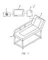
- Figure 1illustrates an intelligent medical vigilance system 1, which comprises a bedside unit 3 connected to a sensing array 5 (placed under the patient) and also to an existing hospital call system 7 via an interface 9.
- a signal processor and an alarm processorthat measure the data and evaluate whether a clinically significant event is occurring.
- the present inventioncan also be used as a monitoring system in vehicles.
- the bedside unit 3is a wall-mounted unit with a display 9 that becomes active (comes on) when an alarm condition is enabled or on command by the nurse, by touching any key. It has a number of dedicated and softkey buttons and controls for entering information, setting up specific items and interacting with the system.
- the sensing array 5be in the form of a thin, piezoelectric film sensing array sheathed in soft padding that is easily cleaned. It is placed in the patient's bed 11, under the bottom sheet (and other padding if needed), not directly in contact with the skin of the patient.
- the sensing array 5may be incorporated into soft padding under the bottom sheet of a patient's bed.
- the nurse call feature 7is made up of hardware, software and cabling to connect to the nurse call system already installed in the hospital or care facility.
- the signal processoris made up of hardware and software that accepts, buffers and converts the sensor array signal from analog to digital format for subsequent processing. Trend information is recorded and available for study.
- the alarm processoruses logic to monitor the parameter trends and determines when a negative condition is occurring. It then actuates the alarm circuitry for local and/or remote alarm. Soft alarms may be utilized to report adverse trends before emergency situation arises.
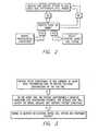
- Figure 2shows a schematic diagram of the monitoring process of the present invention.
- Figure 3is a diagram showing progression from normal patient condition to negative event and nurse response.
- the usercan set "hard” alarm limits - those high and low single-parameter limits that, when passed, will cause the alarm indication, signal and tone to be transmitted to the caregiver by any number of means.
- the caregiverresponds to correct the situation.
- One problem caused by such alarmsis that of false positive alarms - those alarms that sound because the set threshold is passed momentarily, but that are not associated with a clinically significant event.
- the alarm limitsmay be set close to the patient's present parameter value. The closer these are set, the more likely it is that a minor actual parameter variation, patient movement or other signal "noise" will make the measured parameter surpass the set alarm limit.
- the "hard” alarm limitscan be spread more widely than in conventional intensive care unit monitors. This is done because the patients being monitored may be relatively healthy and mobile compared to typical ICU patients. Because of their high activity level they exhibit a lot of variability in their measured vital parameters such as heart rate, respiratory rate, blood pressure, temperature, cardiac activity, etc. Thus, the clinician wants to watch over these patients' condition, but also wants to avoid false positive alarms that disrupt the patient care workflow and the feelings and outlook of the patient. However, the clinician is still interested in detecting negative trends in the patient so they can react quickly to treat or avoid deeper, more serious problems.
- Figures 4 and 5show the use of alarm limit pairs and algorithms.
- Figure 4is a time plot of multiple parameters, showing various parameter violations and alarm logic.
- Figure 5is multiple parameter alarm table, showing alarm logic.
- the monitor of the present inventionhas two or more distinct alarm limit pairs and algorithms.
- the purpose of the new alarm schemeis to set new thresholds within the previous "hard” limits of each parameter that will catch a patient's worsening condition prior to crossing the old single “hard” limits. This differs from just moving those limits in because these new, soft limits require that both the HR and RR values (in this example) be outside the soft limits to initiate the alarm. If either the HR or RR falls outside a hard limit, then the alarm sounds. If both the HR and RR fall outside the soft limit, but still within the hard limit, then the "soft" alarm sounds. This is best described in Figure 4 .
- the parameters covered by such an alarm schemeare not limited to Heart Rate and Respiratory Rate, used in this example.
- the sensitivity and specificity of the "hard” alarmmay bo improved by using a more-complex algorithm than just "did it pass the limit?" used in many systems. This improvement could take the form of applying a number of approaches including but not limited to neural net and/or fuzzy logic.
- Fuzzy logiccould be applied to the limit as follows: Given one or more measurements of physiological parameters (e.g. heart rate, respiration rate, blood pressure, temperature, etc.) which require an alarm when the measurement is outside of a range (or band), a fuzzy logic type function can be defined as follows:
- Tais typically set to 0.5 if any weak (or soft) condition (or combination of weak conditions) is to cause an alarm. If Ta is set to 1.0 a strong alarm condition from at least one physiological parameter is required for the alarm to sound. If it is desired that the alarm only sound when Physiological parameters are at or above t Hh (n) (or below t Ll (n)), then Ta can be set to N. This method can also be used when the same physiological parameter is measured by multiple means.
- the F(p) functionswould most likely be the same for each measurement and Ta could be set to 1.0 such that if either device exceeded the t H limits, the alarm would sound.
- the alarm violation type(hard, soft, etc.) may be differentiated from each other or not, depending on the needs for the specific clinical application (ICU versus General Care Floor, etc.).
- the alarmsmay be set individually for each parameter as soft high and soft low or may be set by using a fixed percentage, such as 10% within the range of the hard limits for each parameter.
- the logiccan also be extended to more than two alarms if needed.
- the sensitivity of both the "hard” and “soft” limitsalso may be improved by delaying the alarm until the monitor determines that a signal has passed a limit for a certain length of time, such as 10 seconds. In this way, momentary changes in a signal having no clinical significance can be ignored.
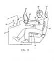
- FIG. 6is a diagram of the present invention installed in a vehicle.
- the intelligent medical vigilance system of the present inventioncan easily be adapted for use as a monitoring system for operators of motor vehicles, aircraft or other devices.
- the sensing array of the present inventionis installed in one or more of the following regions of a motor vehicle: the seat 13, seatback 15, headrest 17, steering wheel 19, driving jacket 21, or a driving cap 23.
- One or more sensor arraysmay be located in each general location to provide for improved feedback.
- the vehicle operatormay also carry a wrist attachment 25 or a necklace 27 with built in sensor arrays.
- the sensor arrays in the vehicletransmit information about the patient to a central processor 29 built into the vehicle via hardwiring 31 or wireless 33 technologies.
- the processoranalyzes the incoming information and outputs data as needed.
- the vigilance systemcan be use to alert drivers to approaching sleep states or other potentially hazardous physical conditions in order to reduce accidents.
- the sensorscan be configured to measure a variety of parameters, such as heart rate, respiration rate, blood pressure, temperature, cardiac output and movement of the vehicle operator.
- the intelligent monitoring system in vehiclesuses similar alarm schemes to those in a hospital setting.
Landscapes
- Health & Medical Sciences (AREA)
- Life Sciences & Earth Sciences (AREA)
- Engineering & Computer Science (AREA)
- Biomedical Technology (AREA)
- Public Health (AREA)
- General Health & Medical Sciences (AREA)
- Medical Informatics (AREA)
- Animal Behavior & Ethology (AREA)
- Veterinary Medicine (AREA)
- Pathology (AREA)
- Molecular Biology (AREA)
- Surgery (AREA)
- Biophysics (AREA)
- Physics & Mathematics (AREA)
- Heart & Thoracic Surgery (AREA)
- Cardiology (AREA)
- Physiology (AREA)
- Business, Economics & Management (AREA)
- General Business, Economics & Management (AREA)
- Epidemiology (AREA)
- Primary Health Care (AREA)
- Computer Networks & Wireless Communication (AREA)
- Pulmonology (AREA)
- Measuring And Recording Apparatus For Diagnosis (AREA)
- Measurement Of The Respiration, Hearing Ability, Form, And Blood Characteristics Of Living Organisms (AREA)
Description
- This application claims the benefit of
U.S. Provisional Application No. 60/526,612 filed December 4, 2003 - The present invention relates generally to monitoring systems, and more particularly has reference to intelligent medical vigilance systems used for monitoring patients, automobile drivers, or other persons whose physiological condition may undergo a change signifying a deterioration in condition, a tendency toward drowsiness, or other state that may have important consequences for that person or for others.
- Medical monitors have been in use for many years. Typically, medical monitors include patient monitors prescribed by a physician in a non-ICU setting.
- While typical devices may be suitable for the particular purpose to which they address, they are not as suitable for providing an invisible "safety net" for a patient that will observe and analyze, and, only in the event of a clinically significant negative condition, notify and report the event to the care staff utilizing the hospital's existing nurse call system.
- Patent application
US 5,724,025 by Tavory , discloses a portable vital signs monitor including a plurality of sensors and an alarm mechanism which is designed to activate when one or more predetermined set points or combination of set points stored in the data storage is exceeded. - Patent application
US 5,585,785 by Gwin et al. , discloses a driver alarm with a pressure transducer attached along the circumference of the steering wheel of a vehicle to measure hand grip pressure on the wheel and sound an alarm when the pressure falls below a lower limit and when the transient behavior of the pressure signal deteriorates substantially. - The main problem with conventional medical monitors is they are designed to respond to rapidly changing situations (found, in ICUs) and thus have a high false alarm rate. Outside the intensive care unit, these monitors are not usually connected to a remote alarm, so local alarms sound, disturbing the patient, their family and friends and the workflow of the various clinicians providing care to the patient. Many attempts have been made to make alarms more meaningful.
- Another problem is that standard devices require contact directly to the patient's skin or body via cables or wires. This means constraining the patient's movement to prevent disconnecting the sensors and also creates a danger of entanglement or strangulation from the cables. Additionally, these devices are relatively expensive to purchase and somewhat complex to operate, requiring a trained individual to operate property.
- Thus, a need exists for simpler, less expensive and more accurate methods for noninvasive vital sign monitoring of significant negative conditions and reporting these events. This invention addresses these and other needs.
- Briefly, and in general terms, the present invention involves a new and improved intelligent medical vigilance method and apparatus for providing an invisible "safety net" that observes and analyzes a person's vital signs. Only in the event of a clinically significant negative condition will the device notify and report the event to the person or the care staff of a health care facility, utilizing, for example, a hospital's existing nurse call system. In so doing, the invention extends the vigilance capability and "reach" of the hospital clinical staff so that their resources can be more effectively applied.
- The present invention has many of the advantages of the medical monitors mentioned heretofore and many novel features that result in a new intelligent medical vigilance system which is not anticipated, rendered obvious, suggested, or even implied by any of the prior art medical monitors, either alone or in any combination thereof.
- In a presently preferred embodiment, by way of axample and not necessarily by way of limitation, the invention generally comprises a bedside unit connected to a sensing array (placed under the patient) and to an existing hospital nurse call system via an interface. The sensing array preferably is a non-invasive piezoelectric sensing film or other similar sensing technology, with an array of sensors installed in soft padding under the bottom sheet of the patient's hospital bed. The sensing array is not directly in contact with the skin of the patient. Within the physical bedside unit are a signal processor and an alarm processor that measure the data and evaluate whether a clinically significant event is occurring.
- The bedside unit is a wall-mounted unit with a display that becomes active (comes on) when an alarm condition is enabled or on command by the nurse, by touching any key. It has a number of dedicated and softkey buttons and controls for entering information, setting up specific items and interacting with the system.
- The sensing array is a thin, piezoelectric film or other similar sensing technology, with an array of sensors sheathed in soft padding that is easily cleaned. It is placed in the patient's bed, under the bottom sheet (and other padding if needed), not directly in contact with the skin of the patient. It can be integrated into the mattress coverlet, if desired. The monitoring system of the present invention may also be used in chairs to monitor the state of relaxation of a subject via heart rate, blood pressure and respiration rates.
- The nurse call feature is made up of hardware, software and cabling to connect to a nurse call system already installed in the hospital or care facility. The signal processor is made up of hardware and software that accepts, buffers and converts the sensor array signal from analog to digital format for subsequent processing. The alarm processor uses logic to monitor the parameter trends and determines when a negative condition is occurring. It then actuates the alarm circuitry for local and/or remote alarm. Soft alarms may be used to report adverse trends before an emergency condition arises. All alarms may interact with the existing nurse call system in the hospital.
- In alternative embodiments, the intelligent medical vigilance system of the present invention can be adapted for use as a monitoring system for operators of motor vehicles, aircraft or other devices. The present invention is installed in one or more of the following regions of a motor vehicle: the seat, seatback, headrest, steering wheel, driving jacket, or a driving cap. One or more sensors may be located in each general location to provide for improved feedback. The vehicle operator may also carry a wrist attachment or a necklace with built in sensors.
- The sensors in the vehicle transmit information about the patient to a central processor built into the vehicle via hardwiring or wireless technology. The processor analyzes the incoming information and outputs data as needed. The vigilance system can be used to alert drivers to approaching sleep states or other potentially hazardous physical conditions in order to reduce accidents. The sensors measure heart rate, respiration rate and movement of the vehicle operator.
- Background noise signals are actively cancelled out to provide an accurate reading of the patients heart rate, respiration rate and blood pressure. This cancellation allows the monitoring system to operate effectively in high background noise environments.
- Trend information is also recorded and available for study.
- The present invention overcomes many of the shortcomings of the prior art devices.
- In a preferred embodiment, the present invention provides an intelligent medical vigilance system for providing an invisible "safety net" for the patient that will observe and analyze, and, only in the event of a clinically significant negative condition, notify and report the event to the care staff utilising the hospital's existing nurse call system.
- In a further preferred embodiment, the invention provides an intelligent medical vigilance system that observes (monitors) multiple physiological signals without direct skin contact.
- In yet a further embodiment, the invention provides an intelligent medical vigilance system that analyzes the information to determine whether the parameters are within normal limits or are tending to go in a clinically negative direction.
- In a further aspect, the invention provides an intelligent medical vigilance system that reports the physiological parameters and provides a trend of them over time.
- In yet a further aspect, the invention provides an intelligent medial vigilance system that notifies the nursing care staff when a consistently negative situation is detected via the existing nurse call system used in the facility.
- In still a further aspect, the invention provides an intelligent medical vigilance system that persistently reminds nursing of continued violations or worsening situation until interventions are successful. This aspect provides an intelligent medical vigilance system that extends the vigilance capability and "reach" of the busy clinical staff so they can spend time where it has the best clinical effect.
- In another aspect, the invention provides a sensor system within vehicles that alerts operators to dangerous physiological conditions that would impair the operator's ability to operate equipment safely.
- These and other advantages of the invention will become more apparent from the following detailed description, taken in conjunction with the accompanying drawings, which illustrate, by way of example, the features of the invention.
Figure 1 is a diagram of the vigilance monitoring system of the present invention.Figure 2 is a block diagram of the system functions.Figure 3 is a diagram showing progression from normal patient condition to negative event and nurse response.Figure 4 is a time plot of multiple parameters, showing various parameter violations and alarm logic.Figure 5 is multiple parameter alarm table, showing alarm logic.Figure 6 is a diagram showing various configurations of sensors in a vehicle.Figure 1 illustrates an intelligentmedical vigilance system 1, which comprises abedside unit 3 connected to a sensing array 5 (placed under the patient) and also to an existinghospital call system 7 via aninterface 9. Within thephysical bedside unit 3 are a signal processor and an alarm processor that measure the data and evaluate whether a clinically significant event is occurring. The present invention can also be used as a monitoring system in vehicles.- The
bedside unit 3 is a wall-mounted unit with adisplay 9 that becomes active (comes on) when an alarm condition is enabled or on command by the nurse, by touching any key. It has a number of dedicated and softkey buttons and controls for entering information, setting up specific items and interacting with the system. - While various types of sensors can be used, it is preferred that the
sensing array 5 be in the form of a thin, piezoelectric film sensing array sheathed in soft padding that is easily cleaned. It is placed in the patient'sbed 11, under the bottom sheet (and other padding if needed), not directly in contact with the skin of the patient. Thesensing array 5 may be incorporated into soft padding under the bottom sheet of a patient's bed. - The
nurse call feature 7 is made up of hardware, software and cabling to connect to the nurse call system already installed in the hospital or care facility. - The signal processor is made up of hardware and software that accepts, buffers and converts the sensor array signal from analog to digital format for subsequent processing. Trend information is recorded and available for study.
- The alarm processor uses logic to monitor the parameter trends and determines when a negative condition is occurring. It then actuates the alarm circuitry for local and/or remote alarm. Soft alarms may be utilized to report adverse trends before emergency situation arises.
Figure 2 shows a schematic diagram of the monitoring process of the present invention.Figure 3 is a diagram showing progression from normal patient condition to negative event and nurse response.- In all patient monitoring devices with alarms the user can set "hard" alarm limits - those high and low single-parameter limits that, when passed, will cause the alarm indication, signal and tone to be transmitted to the caregiver by any number of means. The caregiver responds to correct the situation. One problem caused by such alarms is that of false positive alarms - those alarms that sound because the set threshold is passed momentarily, but that are not associated with a clinically significant event. In order to monitor the patient closely the alarm limits may be set close to the patient's present parameter value. The closer these are set, the more likely it is that a minor actual parameter variation, patient movement or other signal "noise" will make the measured parameter surpass the set alarm limit.
- Few if any alarms use any delay or additional processing other that the filtering used to compute the average of and display the parameter's value. There have been many attempts to measure the inadequacy of such simple alarms in the intensive care unit. There are also methodologies used to dolay alarming until a certain time since passage outside the range integrated with the extent of the deviation beyond the set range is exceeded.
- In an intelligent vigilance monitor such as the one used in this invention, the "hard" alarm limits can be spread more widely than in conventional intensive care unit monitors. This is done because the patients being monitored may be relatively healthy and mobile compared to typical ICU patients. Because of their high activity level they exhibit a lot of variability in their measured vital parameters such as heart rate, respiratory rate, blood pressure, temperature, cardiac activity, etc. Thus, the clinician wants to watch over these patients' condition, but also wants to avoid false positive alarms that disrupt the patient care workflow and the feelings and outlook of the patient. However, the clinician is still interested in detecting negative trends in the patient so they can react quickly to treat or avoid deeper, more serious problems.
Figures 4 and 5 show the use of alarm limit pairs and algorithms.Figure 4 is a time plot of multiple parameters, showing various parameter violations and alarm logic.Figure 5 is multiple parameter alarm table, showing alarm logic.- To accomplish a balanced response, the monitor of the present invention has two or more distinct alarm limit pairs and algorithms. The purpose of the new alarm scheme is to set new thresholds within the previous "hard" limits of each parameter that will catch a patient's worsening condition prior to crossing the old single "hard" limits. This differs from just moving those limits in because these new, soft limits require that both the HR and RR values (in this example) be outside the soft limits to initiate the alarm. If either the HR or RR falls outside a hard limit, then the alarm sounds. If both the HR and RR fall outside the soft limit, but still within the hard limit, then the "soft" alarm sounds. This is best described in
Figure 4 . - The parameters covered by such an alarm scheme are not limited to Heart Rate and Respiratory Rate, used in this example. In addition, the sensitivity and specificity of the "hard" alarm may bo improved by using a more-complex algorithm than just "did it pass the limit?" used in many systems. This improvement could take the form of applying a number of approaches including but not limited to neural net and/or fuzzy logic.
- Fuzzy logic could be applied to the limit as follows: Given one or more measurements of physiological parameters (e.g. heart rate, respiration rate, blood pressure, temperature, etc.) which require an alarm when the measurement is outside of a range (or band), a fuzzy logic type function can be defined as follows:


- The sum of N different physiological fuzzy logic functions can be used to establish an alarm equation (See alarm truth function above) described further as follows: When A >= Ta, the alarm sounds, otherwise it does not. Ta is typically set to 0.5 if any weak (or soft) condition (or combination of weak conditions) is to cause an alarm. If Ta is set to 1.0 a strong alarm condition from at least one physiological parameter is required for the alarm to sound. If it is desired that the alarm only sound when Physiological parameters are at or above tHh(n) (or below tLl(n)), then Ta can be set to N. This method can also be used when the same physiological parameter is measured by multiple means.
- In the case of two measurements of the same physiological parameter, the F(p) functions would most likely be the same for each measurement and Ta could be set to 1.0 such that if either device exceeded the tH limits, the alarm would sound. The alarm violation type (hard, soft, etc.) may be differentiated from each other or not, depending on the needs for the specific clinical application (ICU versus General Care Floor, etc.). The alarms may be set individually for each parameter as soft high and soft low or may be set by using a fixed percentage, such as 10% within the range of the hard limits for each parameter. The logic can also be extended to more than two alarms if needed.
- The sensitivity of both the "hard" and "soft" limits also may be improved by delaying the alarm until the monitor determines that a signal has passed a limit for a certain length of time, such as 10 seconds. In this way, momentary changes in a signal having no clinical significance can be ignored.
Figure 6 is a diagram of the present invention installed in a vehicle. The intelligent medical vigilance system of the present invention can easily be adapted for use as a monitoring system for operators of motor vehicles, aircraft or other devices. The sensing array of the present invention is installed in one or more of the following regions of a motor vehicle: theseat 13,seatback 15,headrest 17,steering wheel 19, drivingjacket 21, or a drivingcap 23. One or more sensor arrays may be located in each general location to provide for improved feedback. The vehicle operator may also carry awrist attachment 25 or anecklace 27 with built in sensor arrays.- The sensor arrays in the vehicle transmit information about the patient to a
central processor 29 built into the vehicle viahardwiring 31 orwireless 33 technologies. The processor analyzes the incoming information and outputs data as needed. The vigilance system can be use to alert drivers to approaching sleep states or other potentially hazardous physical conditions in order to reduce accidents. The sensors can be configured to measure a variety of parameters, such as heart rate, respiration rate, blood pressure, temperature, cardiac output and movement of the vehicle operator. The intelligent monitoring system in vehicles uses similar alarm schemes to those in a hospital setting. - Background noise signals are actively cancelled out to provide an accurate reading of the operator's measured physiological parameters. This cancellation allows the monitoring system to operate effectively in high background noise environments.
- While a particular form of the invention has been illustrated and described, it will also be apparent to those skilled in the art that various modifications can be made without departing from the spirit and scope of the invention. Accordingly, it is not intended that the invention be limited except by the appended claims.


Claims (34)
- A method for monitoring the physiology of a person and providing an alarm to warn of an undesirable condition, comprising:placing adjacent the person a plurality of sensors (5) configured to detect physiological parameters of the person;detecting one or more physiological parameters of the person with said sensors (5);converting the detected one or more physiological parameters into signals;assigning an upper hard range of signal values for each physiological parameter;assigning a lower hard range of signal values for each physiological parameter;analyzing at least two of the signals over a period of time to determine in which range each signal is situated;the method beingcharacterized by further comprising:assigning an upper soft range of signal values below the upper hard range for each physiological parameter, wherein the upper soft range is selected to be a predetermined downward departure from the upper hard range;assigning a lower soft range of signal values above the lower hard range for each physiological parameter, wherein the lower soft range is selected to be a predetermined upward departure from the lower hard range;activating an alarm when at least one signal is in a hard range, andactivating an alarm when at least two signals are in a soft range.
- The method of claim 1, wherein activating an alarm includes activating a hard alarm when at least one signal is in a hard range, and activating a soft alarm when at least two signals are in a soft range.
- The method of claim 1, wherein activating an alarm includes activating an alarm using fuzzy logic to assess the significance of the plurality of signals in relation to the hard and soft ranges.
- The method of claim 1, wherein each said plurality of sensors (5) is configured to detect the same physiological parameter of the person.
- The method of claim 1, wherein each of said plurality of sensors (5) is configured to detect multiple different physiological parameters of the person.
- The method of claim 1, wherein the sensors (5) are configured to detect at least two physiological parameters selected from the group consisting of heart rate, respiration rate, blood pressure, temperature, motion, and noise emission.
- The method of claim 1, wherein the ranges of signal values are assigned by a health care giver and can be selectively varied.
- The method of claim 1, wherein the upper soft range is automatically selected to have a lower limit that is a predetermined percentage of the lower limit of the upper hard range, and the lower soft range is automatically selected to have an upper limit that is a predetermined percentage of the upper limit of the lower hard range.
- The method of claim 1, wherein each parameter is assigned a different soft range.
- The method of claim 1, wherein the magnitude of the upper soft range differs from the magnitude of the lower soft range.
- The method of claim 1, further comprising
communicating an activated alarm to a health care provider through a pre-existing nurse call system within a health care facility. - The method of claim 1, further comprising
selecting signals in the upper ranges which are increasing in value and signals in the lower ranges which are decreasing in value;
activating an alarm when at least one said selected signals is in a hard range; and activating an alarm when at least two of said selected signals are in a soft range. - The method of claim 1, further comprising
applying a fuzzy logic function to each signal within a range; and
activating an alarm when the sum of the fuzzy logic functions exceed a predetermined value. - The method of claim 13, wherein a first predetermined value activates a soft alarm.
- The method of claim 13, wherein a second predetermined value activates a hard alarm.
- The method of claim 1, wherein the upper soft range is automatically selected to have a lower limit that is a fixed percentage of the lower limit of the upper hard range, and the lower soft range is automatically selected to have an upper limit that is a fixed percentage of the upper limit of the lower hard range.
- Apparatus for monitoring the physiology of a person and providing an alarm to warn of an undesirable condition, comprising:a plurality of sensors (5) for detecting one or more physiological parameters of the person;a processor configured to convert each detected one or more physiological parameters into information signals; andan alarm system in communication with the processor, the alarm system being configured to provide one or more alarms;wherein the processor is configured to perform steps including:receiving a designated upper hard range of signal values for each physiological parameterreceiving a designated lower hard range of signal values for each physiological parameter;analyzing at least two of the signals over a period of time to determine in which range of values each signal is situated;where the apparatus ischaracterized by the processor being configured to further perform the following steps:receiving a designated upper soft range of signal values below the upper hard range for each physiological parameter;receiving a designated lower soft range of signal values above the lower hard range for each physiological parameter;activating the alarm when at least one signal is in a hard range; andactivating the alarm when at least two signals are in a soft range.
- The apparatus of claim 17 further comprising an interface (9) for connecting the alarm system to an existing nurse call system (7) in a health care facility.
- The apparatus of claim 17, wherein the processor is housed in a bedside unit (3), for placing alongside a bed (11) for the person.
- The apparatus of claim 19, wherein the bedside unit further comprises a display connected to the processor for displaying physiological data, the display being automatically actuated when an alarm condition occurs.
- The apparatus of claim 19, wherein the bedside unit further comprises a display connected to a processor for displaying physiological data, the display being selectively activated by an attending health care provider.
- The apparatus of claim 17, wherein the sensors (5) are assembled in an array enclosed within a coverlet.
- The apparatus of claim 17, wherein the sensors (5) are disposed within bedding for the person.
- The apparatus of claim 17, wherein the sensors (5) comprise noninvasive sensors formed of piezoelectric material.
- The apparatus of claim 17, wherein the sensors are installed in at least one location selected from the group consisting of a vehicle seat (13), a vehicle seatback (15), a vehicle headrest (17), a vehicle steering wheel (19), a driving jacket (21), a driving cap (23), a wrist attachment (25), and a necklace (27).
- The apparatus of claim 17, wherein the processor (29) is located in a vehicle.
- The apparatus of claim 17, wherein the sensors transmit the detected parameters to the processor via wireless technology (33).
- The apparatus of claim 17, wherein the alarm is configured to alert a driver of a vehicle of an approaching sleep state.
- The apparatus of claim 17, wherein the sensors are configured to detect at least two physiological parameters selected from the group consisting of heart rate, respiration rate, blood pressure, temperature, cardiac output and movement of the person.
- The apparatus of claim 17, wherein the processor is further configured such that activating the alarm includes activating a hard alarm when at least one signal is in a hard range, and activating a soft alarm when at least two signals are in a soft range.
- The apparatus of claim 17, wherein the sensors are not directly in contact with the person's skin.
- The method of claim 1, wherein activating an alarm when at least one signal is in a hard range requires that said at least one signal remain in said range for a predetermined period of time to activate said alarm.
- The method of claim 1, wherein activating an alarm when at least two signals are in a soft range requires that said at least one of said signals remain in said range for a predetermined period of time to activate said alarm.
- The apparatus of claim 17, wherein the sensors are placed in soft padding under the bottom sheet of the person's bed (11).
Applications Claiming Priority (2)
| Application Number | Priority Date | Filing Date | Title |
|---|---|---|---|
| US52661203P | 2003-12-04 | 2003-12-04 | |
| PCT/US2004/040379WO2005055824A1 (en) | 2003-12-04 | 2004-12-03 | Intelligent medical vigilance system |
Publications (3)
| Publication Number | Publication Date |
|---|---|
| EP1694202A1 EP1694202A1 (en) | 2006-08-30 |
| EP1694202A4 EP1694202A4 (en) | 2009-06-03 |
| EP1694202B1true EP1694202B1 (en) | 2014-12-31 |
Family
ID=34676633
Family Applications (1)
| Application Number | Title | Priority Date | Filing Date |
|---|---|---|---|
| EP04812817.7AExpired - LifetimeEP1694202B1 (en) | 2003-12-04 | 2004-12-03 | Intelligent medical vigilance system |
Country Status (7)
| Country | Link |
|---|---|
| US (1) | US7304580B2 (en) |
| EP (1) | EP1694202B1 (en) |
| JP (1) | JP2007518470A (en) |
| CN (1) | CN100544667C (en) |
| AU (1) | AU2004296792B2 (en) |
| CA (1) | CA2548231A1 (en) |
| WO (1) | WO2005055824A1 (en) |
Cited By (2)
| Publication number | Priority date | Publication date | Assignee | Title |
|---|---|---|---|---|
| CN104886789A (en)* | 2015-06-29 | 2015-09-09 | 京东方科技集团股份有限公司 | Wrap structure |
| US11322258B2 (en) | 2012-05-22 | 2022-05-03 | Hill-Rom Services, Inc. | Adverse condition detection, assessment, and response systems, methods and devices |
Families Citing this family (190)
| Publication number | Priority date | Publication date | Assignee | Title |
|---|---|---|---|---|
| US6721980B1 (en) | 1998-10-28 | 2004-04-20 | Hill-Fom Services, Inc. | Force optimization surface apparatus and method |
| EP1290652A2 (en) | 2000-05-05 | 2003-03-12 | Hill-Rom Services, Inc. | Hospital monitoring and control system and method |
| BR0110596A (en) | 2000-05-05 | 2005-08-02 | Hill Rom Services Inc | Patient monitoring system, computer system, patient information monitoring system, patient care device, walker device, patient care device, and computer display |
| US7629890B2 (en) | 2003-12-04 | 2009-12-08 | Hoana Medical, Inc. | System and methods for intelligent medical vigilance with bed exit detection |
| US7652581B2 (en)* | 2004-02-18 | 2010-01-26 | Hoana Medical, Inc. | Method and system for integrating a passive sensor array with a mattress for patient monitoring |
| AU2004251778A1 (en)* | 2003-06-26 | 2005-01-06 | Hoana Medical, Inc. | Radiation stress non-invasive blood pressure method |
| WO2005022692A2 (en) | 2003-08-21 | 2005-03-10 | Hill-Rom Services, Inc. | Plug and receptacle having wired and wireless coupling |
| US8403865B2 (en) | 2004-02-05 | 2013-03-26 | Earlysense Ltd. | Prediction and monitoring of clinical episodes |
| US8491492B2 (en) | 2004-02-05 | 2013-07-23 | Earlysense Ltd. | Monitoring a condition of a subject |
| US7314451B2 (en)* | 2005-04-25 | 2008-01-01 | Earlysense Ltd. | Techniques for prediction and monitoring of clinical episodes |
| US8942779B2 (en) | 2004-02-05 | 2015-01-27 | Early Sense Ltd. | Monitoring a condition of a subject |
| US7077810B2 (en) | 2004-02-05 | 2006-07-18 | Earlysense Ltd. | Techniques for prediction and monitoring of respiration-manifested clinical episodes |
| US20050273013A1 (en)* | 2004-06-04 | 2005-12-08 | Kent Lee E | Wireless patient monitoring system |
| US7173525B2 (en)* | 2004-07-23 | 2007-02-06 | Innovalarm Corporation | Enhanced fire, safety, security and health monitoring and alarm response method, system and device |
| US7319386B2 (en) | 2004-08-02 | 2008-01-15 | Hill-Rom Services, Inc. | Configurable system for alerting caregivers |
| US8273018B1 (en) | 2004-12-28 | 2012-09-25 | Cerner Innovation, Inc. | Computerized method for establishing a communication between a bedside care location and a remote care location |
| US7612679B1 (en)* | 2004-12-28 | 2009-11-03 | Cerner Innovation, Inc. | Computerized method and system for providing alerts from a multi-patient display |
| JP2006346093A (en)* | 2005-06-15 | 2006-12-28 | Denso Corp | Intra-vehicle biological information detector |
| US7786874B2 (en) | 2005-12-09 | 2010-08-31 | Samarion, Inc. | Methods for refining patient, staff and visitor profiles used in monitoring quality and performance at a healthcare facility |
| US20070132597A1 (en)* | 2005-12-09 | 2007-06-14 | Valence Broadband, Inc. | Methods and systems for monitoring patient support exiting and initiating response |
| US20080021731A1 (en)* | 2005-12-09 | 2008-01-24 | Valence Broadband, Inc. | Methods and systems for monitoring patient support exiting and initiating response |
| US7911348B2 (en)* | 2005-12-09 | 2011-03-22 | Bee Cave, LLC. | Methods for refining patient, staff and visitor profiles used in monitoring quality and performance at a healthcare facility |
| US7761310B2 (en)* | 2005-12-09 | 2010-07-20 | Samarion, Inc. | Methods and systems for monitoring quality and performance at a healthcare facility |
| JP5312053B2 (en) | 2006-03-06 | 2013-10-09 | センシオテック インコーポレイテッド | Ultra-wideband monitoring system and antenna |
| US8050863B2 (en)* | 2006-03-16 | 2011-11-01 | Gray & Company, Inc. | Navigation and control system for autonomous vehicles |
| US8920343B2 (en) | 2006-03-23 | 2014-12-30 | Michael Edward Sabatino | Apparatus for acquiring and processing of physiological auditory signals |
| ITMI20060652A1 (en)* | 2006-04-04 | 2007-10-05 | I D I Evolution S R L | CONTROL SYSTEM OF AN ELECTRIC MOTOR FOR SURGICAL APPLICATIONS |
| JP4592097B2 (en)* | 2006-04-20 | 2010-12-01 | 日機装株式会社 | Blood purification equipment |
| US7551078B2 (en)* | 2006-05-08 | 2009-06-23 | Ihc Intellectual Asset Management, Llc | Device alert system and method |
| US20080077020A1 (en) | 2006-09-22 | 2008-03-27 | Bam Labs, Inc. | Method and apparatus for monitoring vital signs remotely |
| JP5123320B2 (en)* | 2007-02-08 | 2013-01-23 | アシスト・メディカル・システムズ,インコーポレイテッド | Medical procedure mat and draping system |
| US8585607B2 (en) | 2007-05-02 | 2013-11-19 | Earlysense Ltd. | Monitoring, predicting and treating clinical episodes |
| US8463361B2 (en) | 2007-05-24 | 2013-06-11 | Lifewave, Inc. | System and method for non-invasive instantaneous and continuous measurement of cardiac chamber volume |
| US20090044332A1 (en)* | 2007-08-13 | 2009-02-19 | Valence Broadband, Inc. | Height adjustable patient support platforms |
| US20090044334A1 (en)* | 2007-08-13 | 2009-02-19 | Valence Broadband, Inc. | Automatically adjusting patient platform support height in response to patient related events |
| US8082160B2 (en) | 2007-10-26 | 2011-12-20 | Hill-Rom Services, Inc. | System and method for collection and communication of data from multiple patient care devices |
| US7987069B2 (en)* | 2007-11-12 | 2011-07-26 | Bee Cave, Llc | Monitoring patient support exiting and initiating response |
| US8636670B2 (en) | 2008-05-13 | 2014-01-28 | The Invention Science Fund I, Llc | Circulatory monitoring systems and methods |
| US20090287120A1 (en) | 2007-12-18 | 2009-11-19 | Searete Llc, A Limited Liability Corporation Of The State Of Delaware | Circulatory monitoring systems and methods |
| US9717896B2 (en) | 2007-12-18 | 2017-08-01 | Gearbox, Llc | Treatment indications informed by a priori implant information |
| US8337404B2 (en) | 2010-10-01 | 2012-12-25 | Flint Hills Scientific, Llc | Detecting, quantifying, and/or classifying seizures using multimodal data |
| US8571643B2 (en) | 2010-09-16 | 2013-10-29 | Flint Hills Scientific, Llc | Detecting or validating a detection of a state change from a template of heart rate derivative shape or heart beat wave complex |
| US8382667B2 (en) | 2010-10-01 | 2013-02-26 | Flint Hills Scientific, Llc | Detecting, quantifying, and/or classifying seizures using multimodal data |
| KR20090084625A (en)* | 2008-02-01 | 2009-08-05 | 삼성전자주식회사 | Personalized custom electronic furniture and how to implement it |
| US8161826B1 (en)* | 2009-03-05 | 2012-04-24 | Stryker Corporation | Elastically stretchable fabric force sensor arrays and methods of making |
| US9883809B2 (en) | 2008-05-01 | 2018-02-06 | Earlysense Ltd. | Monitoring, predicting and treating clinical episodes |
| US8882684B2 (en) | 2008-05-12 | 2014-11-11 | Earlysense Ltd. | Monitoring, predicting and treating clinical episodes |
| CN102113034A (en) | 2008-05-12 | 2011-06-29 | 阿列森斯有限公司 | Monitor, predict and manage clinical episodes |
| US9462844B2 (en) | 2008-06-13 | 2016-10-11 | Nike, Inc. | Footwear having sensor system |
| US9549585B2 (en) | 2008-06-13 | 2017-01-24 | Nike, Inc. | Footwear having sensor system |
| US9002680B2 (en) | 2008-06-13 | 2015-04-07 | Nike, Inc. | Foot gestures for computer input and interface control |
| US10070680B2 (en) | 2008-06-13 | 2018-09-11 | Nike, Inc. | Footwear having sensor system |
| US8301219B2 (en)* | 2008-07-16 | 2012-10-30 | The General Hospital Corporation | Patient monitoring systems and methods |
| US10891356B2 (en) | 2008-09-24 | 2021-01-12 | Resmed Sensor Technologies Limited | Contactless and minimal-contact monitoring of quality of life parameters for assessment and intervention |
| EP2346404A4 (en)* | 2008-10-24 | 2013-12-18 | Hill Rom Services Inc | Apparatuses for supporting and monitoring a person |
| US20100204594A1 (en)* | 2009-02-06 | 2010-08-12 | William Miller | Monitoring system |
| US9323894B2 (en) | 2011-08-19 | 2016-04-26 | Masimo Corporation | Health care sanitation monitoring system |
| US10032002B2 (en) | 2009-03-04 | 2018-07-24 | Masimo Corporation | Medical monitoring system |
| JP5749658B2 (en) | 2009-03-04 | 2015-07-15 | マシモ・コーポレイション | Medical monitoring system |
| US10007758B2 (en) | 2009-03-04 | 2018-06-26 | Masimo Corporation | Medical monitoring system |
| WO2010103361A1 (en)* | 2009-03-09 | 2010-09-16 | Abb Research Ltd | Method for determining operator condition, device therefrom and their use in alarm response system in a facility |
| US9002427B2 (en) | 2009-03-30 | 2015-04-07 | Lifewave Biomedical, Inc. | Apparatus and method for continuous noninvasive measurement of respiratory function and events |
| US20100268051A1 (en)* | 2009-04-16 | 2010-10-21 | Ford Global Technologies, Llc | System and method for wellness monitoring in a vehicle |
| US20100274145A1 (en) | 2009-04-22 | 2010-10-28 | Tupin Jr Joe Paul | Fetal monitoring device and methods |
| US8890937B2 (en) | 2009-06-01 | 2014-11-18 | The Curators Of The University Of Missouri | Anonymized video analysis methods and systems |
| EP2281506B1 (en)* | 2009-08-03 | 2013-01-16 | Fico Mirrors, S.A. | Method and system for determining an individual's state of attention |
| US20110301432A1 (en) | 2010-06-07 | 2011-12-08 | Riley Carl W | Apparatus for supporting and monitoring a person |
| US8525680B2 (en) | 2009-09-18 | 2013-09-03 | Hill-Rom Services, Inc. | Apparatuses for supporting and monitoring a condition of a person |
| CN105286843A (en) | 2009-12-09 | 2016-02-03 | 耐克创新有限合伙公司 | Athletic performance monitoring system utilizing heart rate information |
| US9554756B2 (en)* | 2009-12-15 | 2017-01-31 | Shenzhen Mindray Bio-Medical Electronics Co. Ltd. | Systems and methods for customizing a multiple alarm system in a portable patient monitor |
| JP2013522588A (en) | 2010-03-12 | 2013-06-13 | エンハンスド サーフェイス ダイナミクス,インコーポレイテッド | System and method for fast collection of data from pressure sensors in a pressure sensing system |
| US8831732B2 (en) | 2010-04-29 | 2014-09-09 | Cyberonics, Inc. | Method, apparatus and system for validating and quantifying cardiac beat data quality |
| US8649871B2 (en) | 2010-04-29 | 2014-02-11 | Cyberonics, Inc. | Validity test adaptive constraint modification for cardiac data used for detection of state changes |
| US8562536B2 (en) | 2010-04-29 | 2013-10-22 | Flint Hills Scientific, Llc | Algorithm for detecting a seizure from cardiac data |
| US8844073B2 (en) | 2010-06-07 | 2014-09-30 | Hill-Rom Services, Inc. | Apparatus for supporting and monitoring a person |
| US8620625B2 (en) | 2010-07-30 | 2013-12-31 | Hill-Rom Services, Inc. | Above bed sensor |
| US8641646B2 (en) | 2010-07-30 | 2014-02-04 | Cyberonics, Inc. | Seizure detection using coordinate data |
| US9545342B2 (en)* | 2010-09-08 | 2017-01-17 | Fit Assist Medical Inc. | Multifunctional medical monitoring system |
| US12383190B2 (en) | 2011-03-04 | 2025-08-12 | Flint Hills Scientific, Llc | Detecting, assessing and managing extreme seizure events |
| US8684921B2 (en) | 2010-10-01 | 2014-04-01 | Flint Hills Scientific Llc | Detecting, assessing and managing epilepsy using a multi-variate, metric-based classification analysis |
| US8704669B2 (en) | 2010-11-08 | 2014-04-22 | Ford Global Technologies, Llc | Vehicle system reaction to medical conditions |
| CA2955632A1 (en) | 2010-11-10 | 2012-05-18 | Nike Innovate C.V. | Systems and methods for time-based athletic activity measurement and display |
| US8907287B2 (en) | 2010-12-01 | 2014-12-09 | Hill-Rom Services, Inc. | Patient monitoring system |
| US10292625B2 (en) | 2010-12-07 | 2019-05-21 | Earlysense Ltd. | Monitoring a sleeping subject |
| EP2652654A1 (en)* | 2010-12-17 | 2013-10-23 | Koninklijke Philips N.V. | Device for controlling the alarm limit of an alarm device |
| US9901287B2 (en)* | 2010-12-22 | 2018-02-27 | Koninklijke Philips N.V. | Patient monitoring and exception notification |
| US9122775B2 (en) | 2011-01-03 | 2015-09-01 | Ford Global Technologies, Llc | Medical data acquisition and provision |
| US9218735B2 (en)* | 2011-01-06 | 2015-12-22 | Koninklijke Philips N.V. | Wireless patient monitoring system and method for monitoring the physiological status of a patient having a network access point |
| US20120185265A1 (en)* | 2011-01-19 | 2012-07-19 | Ford Global Technologies, Llc | Method and system for patient preparation for a health care facility visit |
| US9964416B2 (en) | 2011-02-04 | 2018-05-08 | Ford Global Technologies, Llc | Methods and systems for locating health facilities based on cost of healthcare |
| US9381420B2 (en) | 2011-02-17 | 2016-07-05 | Nike, Inc. | Workout user experience |
| CA2827684C (en) | 2011-02-17 | 2016-09-27 | Nike International Ltd. | Footwear having sensor system |
| WO2012161768A1 (en) | 2011-02-17 | 2012-11-29 | Nike International Ltd. | Tracking of user performance metrics during a workout session |
| CN103476285B (en) | 2011-02-17 | 2017-06-09 | 耐克创新有限合伙公司 | Shoes with sensor system |
| US9292471B2 (en) | 2011-02-18 | 2016-03-22 | Honda Motor Co., Ltd. | Coordinated vehicle response system and method for driver behavior |
| US8698639B2 (en) | 2011-02-18 | 2014-04-15 | Honda Motor Co., Ltd. | System and method for responding to driver behavior |
| CN102648845A (en)* | 2011-02-23 | 2012-08-29 | 深圳市迈迪加科技发展有限公司 | Automatic wireless monitoring and early-warning system for heartbeat and breath in sleep |
| CN102100558A (en)* | 2011-02-23 | 2011-06-22 | 北京大学深圳研究生院 | Wireless respiration monitoring device |
| US9504390B2 (en) | 2011-03-04 | 2016-11-29 | Globalfoundries Inc. | Detecting, assessing and managing a risk of death in epilepsy |
| US10445846B2 (en) | 2011-04-14 | 2019-10-15 | Elwha Llc | Cost-effective resource apportionment technologies suitable for facilitating therapies |
| US10853819B2 (en) | 2011-04-14 | 2020-12-01 | Elwha Llc | Cost-effective resource apportionment technologies suitable for facilitating therapies |
| US8725239B2 (en) | 2011-04-25 | 2014-05-13 | Cyberonics, Inc. | Identifying seizures using heart rate decrease |
| US9402550B2 (en) | 2011-04-29 | 2016-08-02 | Cybertronics, Inc. | Dynamic heart rate threshold for neurological event detection |
| US9449514B2 (en) | 2011-05-18 | 2016-09-20 | Ford Global Technologies, Llc | Methods and apparatus for adaptive vehicle response to air quality states |
| US9492120B2 (en)* | 2011-07-05 | 2016-11-15 | Saudi Arabian Oil Company | Workstation for monitoring and improving health and productivity of employees |
| US10108783B2 (en) | 2011-07-05 | 2018-10-23 | Saudi Arabian Oil Company | Systems, computer medium and computer-implemented methods for monitoring health of employees using mobile devices |
| US9962083B2 (en) | 2011-07-05 | 2018-05-08 | Saudi Arabian Oil Company | Systems, computer medium and computer-implemented methods for monitoring and improving biomechanical health of employees |
| US9526455B2 (en) | 2011-07-05 | 2016-12-27 | Saudi Arabian Oil Company | Systems, computer medium and computer-implemented methods for monitoring and improving health and productivity of employees |
| US10307104B2 (en) | 2011-07-05 | 2019-06-04 | Saudi Arabian Oil Company | Chair pad system and associated, computer medium and computer-implemented methods for monitoring and improving health and productivity of employees |
| US9844344B2 (en) | 2011-07-05 | 2017-12-19 | Saudi Arabian Oil Company | Systems and method to monitor health of employee when positioned in association with a workstation |
| US9256711B2 (en) | 2011-07-05 | 2016-02-09 | Saudi Arabian Oil Company | Systems, computer medium and computer-implemented methods for providing health information to employees via augmented reality display |
| US9710788B2 (en) | 2011-07-05 | 2017-07-18 | Saudi Arabian Oil Company | Computer mouse system and associated, computer medium and computer-implemented methods for monitoring and improving health and productivity of employees |
| JP2014525086A (en) | 2011-07-05 | 2014-09-25 | サウジ アラビアン オイル カンパニー | Floor mat system and associated computer media for monitoring and improving employee health and productivity, and computer-implemented methods |
| WO2013008187A1 (en) | 2011-07-13 | 2013-01-17 | Enhanced Surface Dynamics, Inc. | Methods and systems for the manufacture and initiation of a pressure detection mat |
| WO2013033524A2 (en) | 2011-08-31 | 2013-03-07 | The Curators Of The University Of Missouri | Hydraulic bed sensor and system for non-invasive monitoring of physiological data |
| US9549677B2 (en) | 2011-10-14 | 2017-01-24 | Flint Hills Scientific, L.L.C. | Seizure detection methods, apparatus, and systems using a wavelet transform maximum modulus algorithm |
| TWI438727B (en)* | 2012-02-15 | 2014-05-21 | Wistron Corp | Driver drowsiness prediction system and method |
| US11684111B2 (en) | 2012-02-22 | 2023-06-27 | Nike, Inc. | Motorized shoe with gesture control |
| US20130213147A1 (en) | 2012-02-22 | 2013-08-22 | Nike, Inc. | Footwear Having Sensor System |
| US20130213146A1 (en) | 2012-02-22 | 2013-08-22 | Nike, Inc. | Footwear Having Sensor System |
| US11071344B2 (en) | 2012-02-22 | 2021-07-27 | Nike, Inc. | Motorized shoe with gesture control |
| US8739639B2 (en) | 2012-02-22 | 2014-06-03 | Nike, Inc. | Footwear having sensor system |
| US9295390B2 (en) | 2012-03-02 | 2016-03-29 | Hill-Rom Services, Inc. | Facial recognition based monitoring systems and methods |
| US10448839B2 (en) | 2012-04-23 | 2019-10-22 | Livanova Usa, Inc. | Methods, systems and apparatuses for detecting increased risk of sudden death |
| US9681836B2 (en) | 2012-04-23 | 2017-06-20 | Cyberonics, Inc. | Methods, systems and apparatuses for detecting seizure and non-seizure states |
| EP2666406A3 (en) | 2012-05-22 | 2013-12-04 | Hill-Rom Services, Inc. | Occupant egress prediction systems, methods and devices |
| WO2014072798A2 (en) | 2012-11-08 | 2014-05-15 | Rondish Co., Ltd | Bed monitoring pad |
| CN103815883A (en)* | 2012-11-17 | 2014-05-28 | 烟台汇通佳仁医疗科技有限公司 | Vital signs sensing system |
| US9043004B2 (en) | 2012-12-13 | 2015-05-26 | Nike, Inc. | Apparel having sensor system |
| CN103070675A (en)* | 2012-12-28 | 2013-05-01 | 深圳市元征软件开发有限公司 | Vehicle-mounted medical monitoring system |
| US10220211B2 (en) | 2013-01-22 | 2019-03-05 | Livanova Usa, Inc. | Methods and systems to diagnose depression |
| US10926133B2 (en) | 2013-02-01 | 2021-02-23 | Nike, Inc. | System and method for analyzing athletic activity |
| US11006690B2 (en) | 2013-02-01 | 2021-05-18 | Nike, Inc. | System and method for analyzing athletic activity |
| US9743861B2 (en) | 2013-02-01 | 2017-08-29 | Nike, Inc. | System and method for analyzing athletic activity |
| US9333136B2 (en) | 2013-02-28 | 2016-05-10 | Hill-Rom Services, Inc. | Sensors in a mattress cover |
| JP6069042B2 (en)* | 2013-03-12 | 2017-01-25 | 日本光電工業株式会社 | Medical alarm system and medical alarm indicator |
| US8984687B2 (en) | 2013-03-14 | 2015-03-24 | Select Comfort Corporation | Partner snore feature for adjustable bed foundation |
| EP2967223B1 (en) | 2013-03-14 | 2017-11-15 | SleepIQ Labs Inc. | Inflatable air mattress with light controls |
| WO2014143634A1 (en) | 2013-03-14 | 2014-09-18 | Nunn Rob | Inflatable air mattress system with detection techniques |
| US9635953B2 (en) | 2013-03-14 | 2017-05-02 | Sleepiq Labs Inc. | Inflatable air mattress autofill and off bed pressure adjustment |
| WO2014152793A1 (en) | 2013-03-14 | 2014-09-25 | Nunn Rob | Inflatable air mattress system architecture |
| JP6110008B2 (en) | 2013-03-14 | 2017-04-05 | セレクト コンフォート コーポレーションSelect Comfort Corporation | Inflatable air mattress snoring detection and response |
| CA2906038C (en) | 2013-03-14 | 2018-02-13 | Select Comfort Corporation | Inflatable air mattress alert and monitoring system |
| US9410857B2 (en) | 2013-03-15 | 2016-08-09 | Nike, Inc. | System and method for analyzing athletic activity |
| US9751534B2 (en) | 2013-03-15 | 2017-09-05 | Honda Motor Co., Ltd. | System and method for responding to driver state |
| US10499856B2 (en) | 2013-04-06 | 2019-12-10 | Honda Motor Co., Ltd. | System and method for biological signal processing with highly auto-correlated carrier sequences |
| US9504416B2 (en) | 2013-07-03 | 2016-11-29 | Sleepiq Labs Inc. | Smart seat monitoring system |
| US9445751B2 (en) | 2013-07-18 | 2016-09-20 | Sleepiq Labs, Inc. | Device and method of monitoring a position and predicting an exit of a subject on or from a substrate |
| WO2015015288A1 (en)* | 2013-08-01 | 2015-02-05 | Rondish Co. Ltd. | Multifunction interface for patient monitoring |
| US20150105687A1 (en)* | 2013-10-11 | 2015-04-16 | Geelux Holding, Ltd. | Method and apparatus for biological evaluation |
| US9722472B2 (en) | 2013-12-11 | 2017-08-01 | Saudi Arabian Oil Company | Systems, computer medium and computer-implemented methods for harvesting human energy in the workplace |
| US10674832B2 (en) | 2013-12-30 | 2020-06-09 | Sleep Number Corporation | Inflatable air mattress with integrated control |
| CA2945694C (en) | 2013-12-30 | 2022-10-25 | Select Comfort Corporation | Inflatable air mattress with integrated control |
| US20150257698A1 (en)* | 2014-03-17 | 2015-09-17 | Oridion Medical 1987 Ltd. | Patient feedback stimulation loop |
| CN104050776B (en)* | 2014-06-17 | 2016-06-22 | 江苏大学 | Old man's sitting drowsiness prompting instrument |
| US10172593B2 (en)* | 2014-09-03 | 2019-01-08 | Earlysense Ltd. | Pregnancy state monitoring |
| US10448749B2 (en) | 2014-10-10 | 2019-10-22 | Sleep Number Corporation | Bed having logic controller |
| US10786408B2 (en) | 2014-10-17 | 2020-09-29 | Stryker Corporation | Person support apparatuses with exit detection systems |
| CN104398358A (en)* | 2014-11-28 | 2015-03-11 | 深圳诺康医疗设备有限公司 | Mattress capable of measuring heart physiological parameter |
| CN104398357B (en)* | 2014-11-28 | 2017-02-22 | 深圳诺康医疗设备有限公司 | Mattress capable of measuring heart physiological parameter |
| JP6665186B2 (en)* | 2014-12-22 | 2020-03-13 | コーニンクレッカ フィリップス エヌ ヴェKoninklijke Philips N.V. | Method and apparatus for providing an alarm |
| EP3242576A4 (en) | 2015-01-05 | 2018-07-25 | Select Comfort Corporation | Bed with user occupancy tracking |
| US9943270B2 (en)* | 2015-06-30 | 2018-04-17 | General Electric Company | Optimization of patient alarm settings for monitoring devices utilizing analytics |
| US10504353B2 (en) | 2015-07-27 | 2019-12-10 | Hill-Rom Services, Inc. | Customized bed exit warnings to modify patient behavior |
| US10149549B2 (en) | 2015-08-06 | 2018-12-11 | Sleep Number Corporation | Diagnostics of bed and bedroom environment |
| US10206630B2 (en) | 2015-08-28 | 2019-02-19 | Foresite Healthcare, Llc | Systems for automatic assessment of fall risk |
| US11864926B2 (en) | 2015-08-28 | 2024-01-09 | Foresite Healthcare, Llc | Systems and methods for detecting attempted bed exit |
| US10475351B2 (en) | 2015-12-04 | 2019-11-12 | Saudi Arabian Oil Company | Systems, computer medium and methods for management training systems |
| US10642955B2 (en) | 2015-12-04 | 2020-05-05 | Saudi Arabian Oil Company | Devices, methods, and computer medium to provide real time 3D visualization bio-feedback |
| US9889311B2 (en) | 2015-12-04 | 2018-02-13 | Saudi Arabian Oil Company | Systems, protective casings for smartphones, and associated methods to enhance use of an automated external defibrillator (AED) device |
| US10628770B2 (en) | 2015-12-14 | 2020-04-21 | Saudi Arabian Oil Company | Systems and methods for acquiring and employing resiliency data for leadership development |
| CN105769132A (en)* | 2016-03-18 | 2016-07-20 | 周红兵 | Wireless body temperature monitoring system based on 2.4G technology |
| US10360787B2 (en) | 2016-05-05 | 2019-07-23 | Hill-Rom Services, Inc. | Discriminating patient care communications system |
| US10453202B2 (en) | 2016-06-28 | 2019-10-22 | Foresite Healthcare, Llc | Systems and methods for use in detecting falls utilizing thermal sensing |
| CN106308778A (en)* | 2016-08-16 | 2017-01-11 | 江西科技师范大学 | Control method and control system for smart home devices |
| US11083418B2 (en) | 2016-11-04 | 2021-08-10 | Wellsense, Inc. | Patient visualization system |
| US10492734B2 (en) | 2016-11-04 | 2019-12-03 | Wellsense, Inc. | Patient visualization system |
| CN106618526A (en)* | 2016-11-17 | 2017-05-10 | 杭州伯仲信息科技有限公司 | Method and system for monitoring sleep |
| WO2018104991A1 (en) | 2016-12-05 | 2018-06-14 | オリンパス株式会社 | Medical monitoring device and program |
| US11172892B2 (en) | 2017-01-04 | 2021-11-16 | Hill-Rom Services, Inc. | Patient support apparatus having vital signs monitoring and alerting |
| US10765379B2 (en)* | 2017-05-01 | 2020-09-08 | Cardiac Pacemakers, Inc. | Systems and methods for medical alert management |
| US10824132B2 (en) | 2017-12-07 | 2020-11-03 | Saudi Arabian Oil Company | Intelligent personal protective equipment |
| CN111770706B (en) | 2017-12-28 | 2023-06-02 | 数眠公司 | A bed with a snore detection feature |
| US11737938B2 (en) | 2017-12-28 | 2023-08-29 | Sleep Number Corporation | Snore sensing bed |
| CN110211703A (en)* | 2018-02-28 | 2019-09-06 | 普天信息技术有限公司 | A kind of sign abnormality alarming method and intelligent mattress system |
| CN112673404A (en)* | 2018-09-13 | 2021-04-16 | 警报城市有限公司 | Multi-partition mattress capable of detecting leaving of bed at high speed |
| US11276289B1 (en) | 2019-07-10 | 2022-03-15 | Objectvideo Labs, Llc | Intelligent seating for wellness monitoring |
| CA3085085A1 (en) | 2019-08-20 | 2021-02-20 | Stryker Corporation | Person support apparatus with adjustable exit detection zones |
| US12279999B2 (en) | 2021-01-22 | 2025-04-22 | Hill-Rom Services, Inc. | Wireless configuration and authorization of a wall unit that pairs with a medical device |
| US12186241B2 (en) | 2021-01-22 | 2025-01-07 | Hill-Rom Services, Inc. | Time-based wireless pairing between a medical device and a wall unit |
Family Cites Families (80)
| Publication number | Priority date | Publication date | Assignee | Title |
|---|---|---|---|---|
| US698207A (en)* | 1900-12-27 | 1902-04-22 | Emile Maertens | Process of cleaning wool. |
| US4320766A (en)* | 1979-03-13 | 1982-03-23 | Instrumentarium Oy | Apparatus in medicine for the monitoring and or recording of the body movements of a person on a bed, for instance of a patient |
| US4509527A (en) | 1983-04-08 | 1985-04-09 | Timex Medical Products Corporation | Cardio-respiration transducer |
| US4562723A (en)* | 1984-07-27 | 1986-01-07 | Hubner Hans J | Method of and apparatus for the measurement of subterranean atmospheric parameters |
| US4926866A (en)* | 1985-10-11 | 1990-05-22 | Lee Arnold St J | System for gathering physiological data |
| US4827763A (en)* | 1986-04-11 | 1989-05-09 | Purdue Research Foundation | Pressure mapping system with capacitive measuring pad |
| US6375621B1 (en)* | 1987-03-06 | 2002-04-23 | Ocean Laboratories, Inc. | Passive apnea monitor |
| IL86759A (en)* | 1988-06-16 | 1992-09-06 | Dror Nedivi | Medical monitoring system |
| US5448996A (en)* | 1990-02-02 | 1995-09-12 | Lifesigns, Inc. | Patient monitor sheets |
| US5144284A (en) | 1991-05-22 | 1992-09-01 | Hammett Rawlings H | Patient-monitoring bed covering device |
| US5137033A (en) | 1991-07-15 | 1992-08-11 | Norton John L | Patient monitoring device |
| US5353793A (en)* | 1991-11-25 | 1994-10-11 | Oishi-Kogyo Company | Sensor apparatus |
| US5416469A (en)* | 1991-12-23 | 1995-05-16 | Colling; Joyce C. | Method for prediction of times of voiding utilizing temperature measurements |
| US5585875A (en)* | 1992-12-22 | 1996-12-17 | Nikon Corporation | Camera having anti-vibration function |
| US5292340A (en)* | 1993-01-04 | 1994-03-08 | Telectronics Pacing Systems, Inc. | Physiologically-calibrated rate adaptive, dual chamber pacemaker |
| US5724025A (en) | 1993-10-21 | 1998-03-03 | Tavori; Itzchak | Portable vital signs monitor |
| SE508285C2 (en)* | 1994-06-07 | 1998-09-21 | Biosys Ab | Method and apparatus for assessing wakefulness and drowsiness at various stages between wakefulness and sleep in a way that is not monitored non-interfering |
| US5802479A (en)* | 1994-09-23 | 1998-09-01 | Advanced Safety Concepts, Inc. | Motor vehicle occupant sensing systems |
| US5590650A (en)* | 1994-11-16 | 1997-01-07 | Raven, Inc. | Non-invasive medical monitor system |
| US5585785A (en) | 1995-03-03 | 1996-12-17 | Gwin; Ronnie | Driver alarm |
| US6671563B1 (en)* | 1995-05-15 | 2003-12-30 | Alaris Medical Systems, Inc. | System and method for collecting data and managing patient care |
| AUPN304895A0 (en)* | 1995-05-19 | 1995-06-15 | Somed Pty Limited | Device for detecting and recording snoring |
| US6050940A (en)* | 1996-06-17 | 2000-04-18 | Cybernet Systems Corporation | General-purpose medical instrumentation |
| DE19637383A1 (en)* | 1996-09-13 | 1998-04-02 | Siemens Ag | Data collection and evaluation apparatus for single elderly person |
| US5808552A (en) | 1996-11-25 | 1998-09-15 | Hill-Rom, Inc. | Patient detection system for a patient-support device |
| US6198394B1 (en)* | 1996-12-05 | 2001-03-06 | Stephen C. Jacobsen | System for remote monitoring of personnel |
| DE69841846D1 (en)* | 1997-03-17 | 2010-09-30 | Adidas Ag | INFORMATION RECONDITIONING SYSTEM FOR PHYSIOLOGICAL SIGNALS |
| US5942979A (en)* | 1997-04-07 | 1999-08-24 | Luppino; Richard | On guard vehicle safety warning system |
| US6011477A (en)* | 1997-07-23 | 2000-01-04 | Sensitive Technologies, Llc | Respiration and movement monitoring system |
| US6014346A (en) | 1998-02-12 | 2000-01-11 | Accucure, L.L.C. | Medical timer/monitor and method of monitoring patient status |
| US6784797B2 (en)* | 1998-02-26 | 2004-08-31 | Bed-Check Corporation | Microprocessor based bed patient monitor |
| US6579231B1 (en)* | 1998-03-27 | 2003-06-17 | Mci Communications Corporation | Personal medical monitoring unit and system |
| US6248064B1 (en)* | 1998-05-26 | 2001-06-19 | Ineedmd.Com,Inc. | Tele-diagnostic device |
| US6086533A (en)* | 1998-06-12 | 2000-07-11 | Children's Medical Center Corporation | Non-invasive in vivo pressure measurement |
| US6146332A (en)* | 1998-07-29 | 2000-11-14 | 3416704 Canada Inc. | Movement detector |
| US6280392B1 (en) | 1998-07-29 | 2001-08-28 | Denso Corporation | Infant condition monitoring system and method using load cell sensor sheet |
| EP0909551B1 (en)* | 1998-08-07 | 2001-03-28 | Hewlett-Packard Company | Selecting limit values for patient monitoring systems |
| US6261237B1 (en)* | 1998-08-20 | 2001-07-17 | Medacoustics, Inc. | Thin film piezoelectric polymer sensor |
| US6687424B1 (en)* | 1998-08-24 | 2004-02-03 | Empirical Technologies Corporation | Sensing pad assembly employing variable coupler fiberoptic sensor |
| EP1109488A1 (en)* | 1998-09-02 | 2001-06-27 | Med-Dev Limited | Method and apparatus for subject monitoring |
| US6491647B1 (en)* | 1998-09-23 | 2002-12-10 | Active Signal Technologies, Inc. | Physiological sensing device |
| SE9803344L (en)* | 1998-10-01 | 2000-04-02 | Biosys Ab | Method and apparatus for monitoring a seated person |
| US6160478A (en)* | 1998-10-27 | 2000-12-12 | Sarcos Lc | Wireless health monitoring system |
| US6398727B1 (en)* | 1998-12-23 | 2002-06-04 | Baxter International Inc. | Method and apparatus for providing patient care |
| JP2000201900A (en)* | 1999-01-11 | 2000-07-25 | Nippon Koden Corp | Biological signal monitoring device |
| DE19983911B4 (en)* | 1999-01-27 | 2018-09-06 | Compumedics Sleep Pty. Ltd. | Wachsamkeitsüberwachungssystem |
| US6821249B2 (en)* | 1999-03-08 | 2004-11-23 | Board Of Regents, The University Of Texas | Temperature monitoring of congestive heart failure patients as an indicator of worsening condition |
| US6224549B1 (en)* | 1999-04-20 | 2001-05-01 | Nicolet Biomedical, Inc. | Medical signal monitoring and display |
| US7475019B2 (en)* | 1999-11-18 | 2009-01-06 | Visicu, Inc. | System and method for physician note creation and management |
| US7433827B2 (en)* | 1999-06-23 | 2008-10-07 | Visicu, Inc. | System and method for displaying a health status of hospitalized patients |
| US7454359B2 (en)* | 1999-06-23 | 2008-11-18 | Visicu, Inc. | System and method for displaying a health status of hospitalized patients |
| US6804656B1 (en)* | 1999-06-23 | 2004-10-12 | Visicu, Inc. | System and method for providing continuous, expert network critical care services from a remote location(s) |
| US8175895B2 (en)* | 1999-06-23 | 2012-05-08 | Koninklijke Philips Electronics N.V. | Remote command center for patient monitoring |
| US7467094B2 (en)* | 1999-06-23 | 2008-12-16 | Visicu, Inc. | System and method for accounting and billing patients in a hospital environment |
| DE19929328A1 (en)* | 1999-06-26 | 2001-01-04 | Daimlerchrysler Aerospace Ag | Device for long-term medical monitoring of people |
| WO2001005297A2 (en)* | 1999-07-21 | 2001-01-25 | Daniel David | Physiological measuring system comprising a garment in the form of a sleeve or glove and sensing apparatus incorporated in the garment |
| JP3820811B2 (en) | 1999-08-02 | 2006-09-13 | 株式会社デンソー | Respiratory system disease monitoring device |
| US6984207B1 (en) | 1999-09-14 | 2006-01-10 | Hoana Medical, Inc. | Passive physiological monitoring (P2M) system |
| AU3884601A (en)* | 1999-09-21 | 2001-04-24 | Hommed, Llc | In-home patient monitoring system |
| US6681003B2 (en)* | 1999-10-05 | 2004-01-20 | Lifecor, Inc. | Data collection and system management for patient-worn medical devices |
| US6497658B2 (en)* | 1999-12-19 | 2002-12-24 | Michael F. Roizen | Alarm upon detection of impending sleep state |
| US6616606B1 (en)* | 2000-05-19 | 2003-09-09 | Welch Allyn Protocol, Inc. | Patient monitoring system |
| US6468234B1 (en) | 2000-07-14 | 2002-10-22 | The Board Of Trustees Of The Leland Stanford Junior University | SleepSmart |
| US7652581B2 (en)* | 2004-02-18 | 2010-01-26 | Hoana Medical, Inc. | Method and system for integrating a passive sensor array with a mattress for patient monitoring |
| US7666151B2 (en)* | 2002-11-20 | 2010-02-23 | Hoana Medical, Inc. | Devices and methods for passive patient monitoring |
| US6699193B2 (en)* | 2000-09-29 | 2004-03-02 | New Health Sciences, Inc. | Decision support systems and methods for assessing vascular health |
| US6445299B1 (en)* | 2001-01-29 | 2002-09-03 | Antonio Rojas, Jr. | Retrofit for patient call system and method therefor |
| US6611206B2 (en)* | 2001-03-15 | 2003-08-26 | Koninklijke Philips Electronics N.V. | Automatic system for monitoring independent person requiring occasional assistance |
| US6585645B2 (en)* | 2001-05-16 | 2003-07-01 | Ge Medical Systems Information Technologies, Inc. | System for and method of establishing monitoring alarm limits based on physiological variables |
| US6754516B2 (en)* | 2001-07-19 | 2004-06-22 | Nellcor Puritan Bennett Incorporated | Nuisance alarm reductions in a physiological monitor |
| DE10153988B4 (en)* | 2001-11-06 | 2011-07-21 | Grohe AG, 58675 | Setpoint adjuster on a thermostatically controlled mixing valve |
| US6822571B2 (en)* | 2001-11-15 | 2004-11-23 | Stryker Corporation | Patient movement detection system for a bed including a load cell mounting assembly |
| JP2003157984A (en)* | 2001-11-19 | 2003-05-30 | Hitachi Ltd | Street light control system linked to location information terminal |
| US6822573B2 (en)* | 2002-01-18 | 2004-11-23 | Intelligent Mechatronic Systems Inc. | Drowsiness detection system |
| US6822564B2 (en)* | 2002-01-24 | 2004-11-23 | Masimo Corporation | Parallel measurement alarm processor |
| JP2003271747A (en)* | 2002-03-18 | 2003-09-26 | Tateyama Kagaku Kogyo Kk | Health managing apparatus, notice managing apparatus, and health management system |
| EP1494586A4 (en) | 2002-03-25 | 2009-07-22 | Hoana Medical Inc | Passive physiological monitoring (p2m) system |
| US6774797B2 (en)* | 2002-05-10 | 2004-08-10 | On Guard Plus Limited | Wireless tag and monitoring center system for tracking the activities of individuals |
| US6809643B1 (en)* | 2003-03-18 | 2004-10-26 | The United States Of America As Represented By The Administrator Of The National Aeronautics And Space Administration | Health monitoring system for car seat |
| AU2004251778A1 (en) | 2003-06-26 | 2005-01-06 | Hoana Medical, Inc. | Radiation stress non-invasive blood pressure method |
- 2004
- 2004-12-03EPEP04812817.7Apatent/EP1694202B1/ennot_activeExpired - Lifetime
- 2004-12-03CNCNB2004800387841Apatent/CN100544667C/ennot_activeExpired - Fee Related
- 2004-12-03WOPCT/US2004/040379patent/WO2005055824A1/enactiveApplication Filing
- 2004-12-03CACA002548231Apatent/CA2548231A1/ennot_activeAbandoned
- 2004-12-03USUS11/004,589patent/US7304580B2/ennot_activeExpired - Fee Related
- 2004-12-03JPJP2006542747Apatent/JP2007518470A/enactivePending
- 2004-12-03AUAU2004296792Apatent/AU2004296792B2/ennot_activeCeased
Cited By (2)
| Publication number | Priority date | Publication date | Assignee | Title |
|---|---|---|---|---|
| US11322258B2 (en) | 2012-05-22 | 2022-05-03 | Hill-Rom Services, Inc. | Adverse condition detection, assessment, and response systems, methods and devices |
| CN104886789A (en)* | 2015-06-29 | 2015-09-09 | 京东方科技集团股份有限公司 | Wrap structure |
Also Published As
| Publication number | Publication date |
|---|---|
| US7304580B2 (en) | 2007-12-04 |
| CN1897871A (en) | 2007-01-17 |
| US20050190062A1 (en) | 2005-09-01 |
| CN100544667C (en) | 2009-09-30 |
| AU2004296792A1 (en) | 2005-06-23 |
| WO2005055824A1 (en) | 2005-06-23 |
| EP1694202A1 (en) | 2006-08-30 |
| AU2004296792B2 (en) | 2012-04-19 |
| HK1094861A1 (en) | 2007-04-13 |
| EP1694202A4 (en) | 2009-06-03 |
| CA2548231A1 (en) | 2005-06-23 |
| JP2007518470A (en) | 2007-07-12 |
Similar Documents
| Publication | Publication Date | Title |
|---|---|---|
| EP1694202B1 (en) | Intelligent medical vigilance system | |
| US9767667B2 (en) | Systems and methods for monitoring physiology with unable-to-measure alerts | |
| JP6947875B2 (en) | Biological information output device | |
| CA2845982C (en) | Methods, systems, and devices for monitoring and displaying medical parameters for a patient | |
| EP2473107B1 (en) | Consciousness monitoring | |
| JP4029177B2 (en) | Unconstrained biological information detection mat and biological information detection device | |
| WO2001033457A1 (en) | Apparatus and method for providing medical services over a communication network | |
| US20100268124A1 (en) | Method and apparatus for providing contraction information during labour | |
| JP6139615B2 (en) | Anomaly reporting system, anomaly reporting method and program | |
| JP2001187030A5 (en) | Unrestrained biological information detection mat and biological information detection device | |
| JP2004097495A (en) | Sleep state determination device and sleep monitoring system | |
| JP2002052010A (en) | Sleeping condition monitoring device | |
| WO2017038966A1 (en) | Bio-information output device, bio-information output method and program | |
| JP7347921B2 (en) | Alarm information processing device and alarm information processing program | |
| JP2001120507A (en) | Apparatus for detecting vital sign and judging abnormality | |
| HK1094861B (en) | Intelligent medical vigilance system | |
| JP7083052B2 (en) | Abnormality notification system and smartphone | |
| AU2020104028A4 (en) | IAS- Patients Monitoring System: Monitoring of High-Risk Indian Patients Using Artificial Intelligence System | |
| JPH11267106A (en) | Bioactivity detecting sensor, bedding using the same, and bioactivity abnormality detecting device |
Legal Events
| Date | Code | Title | Description |
|---|---|---|---|
| PUAI | Public reference made under article 153(3) epc to a published international application that has entered the european phase | Free format text:ORIGINAL CODE: 0009012 | |
| 17P | Request for examination filed | Effective date:20060703 | |
| AK | Designated contracting states | Kind code of ref document:A1 Designated state(s):AT BE BG CH CY CZ DE DK EE ES FI FR GB GR HU IE IS IT LI LT LU MC NL PL PT RO SE SI SK TR | |
| DAX | Request for extension of the european patent (deleted) | ||
| REG | Reference to a national code | Ref country code:HK Ref legal event code:DE Ref document number:1094861 Country of ref document:HK | |
| A4 | Supplementary search report drawn up and despatched | Effective date:20090508 | |
| RIC1 | Information provided on ipc code assigned before grant | Ipc:A61B 5/00 20060101AFI20050629BHEP Ipc:G08B 23/00 20060101ALI20090430BHEP Ipc:G08B 21/04 20060101ALI20090430BHEP Ipc:G06F 19/00 20060101ALI20090430BHEP | |
| 17Q | First examination report despatched | Effective date:20100716 | |
| GRAP | Despatch of communication of intention to grant a patent | Free format text:ORIGINAL CODE: EPIDOSNIGR1 | |
| INTG | Intention to grant announced | Effective date:20140704 | |
| GRAS | Grant fee paid | Free format text:ORIGINAL CODE: EPIDOSNIGR3 | |
| GRAA | (expected) grant | Free format text:ORIGINAL CODE: 0009210 | |
| RAP1 | Party data changed (applicant data changed or rights of an application transferred) | Owner name:HOANA MEDICAL, INC. | |
| AK | Designated contracting states | Kind code of ref document:B1 Designated state(s):AT BE BG CH CY CZ DE DK EE ES FI FR GB GR HU IE IS IT LI LT LU MC NL PL PT RO SE SI SK TR | |
| REG | Reference to a national code | Ref country code:GB Ref legal event code:FG4D Ref country code:CH Ref legal event code:EP | |
| REG | Reference to a national code | Ref country code:IE Ref legal event code:FG4D | |
| REG | Reference to a national code | Ref country code:AT Ref legal event code:REF Ref document number:703865 Country of ref document:AT Kind code of ref document:T Effective date:20150215 | |
| REG | Reference to a national code | Ref country code:DE Ref legal event code:R096 Ref document number:602004046445 Country of ref document:DE Effective date:20150219 | |
| PG25 | Lapsed in a contracting state [announced via postgrant information from national office to epo] | Ref country code:FI Free format text:LAPSE BECAUSE OF FAILURE TO SUBMIT A TRANSLATION OF THE DESCRIPTION OR TO PAY THE FEE WITHIN THE PRESCRIBED TIME-LIMIT Effective date:20141231 Ref country code:LT Free format text:LAPSE BECAUSE OF FAILURE TO SUBMIT A TRANSLATION OF THE DESCRIPTION OR TO PAY THE FEE WITHIN THE PRESCRIBED TIME-LIMIT Effective date:20141231 | |
| REG | Reference to a national code | Ref country code:NL Ref legal event code:VDEP Effective date:20141231 | |
| REG | Reference to a national code | Ref country code:LT Ref legal event code:MG4D | |
| PG25 | Lapsed in a contracting state [announced via postgrant information from national office to epo] | Ref country code:SE Free format text:LAPSE BECAUSE OF FAILURE TO SUBMIT A TRANSLATION OF THE DESCRIPTION OR TO PAY THE FEE WITHIN THE PRESCRIBED TIME-LIMIT Effective date:20141231 Ref country code:GR Free format text:LAPSE BECAUSE OF FAILURE TO SUBMIT A TRANSLATION OF THE DESCRIPTION OR TO PAY THE FEE WITHIN THE PRESCRIBED TIME-LIMIT Effective date:20150401 | |
| REG | Reference to a national code | Ref country code:AT Ref legal event code:MK05 Ref document number:703865 Country of ref document:AT Kind code of ref document:T Effective date:20141231 | |
| PG25 | Lapsed in a contracting state [announced via postgrant information from national office to epo] | Ref country code:NL Free format text:LAPSE BECAUSE OF FAILURE TO SUBMIT A TRANSLATION OF THE DESCRIPTION OR TO PAY THE FEE WITHIN THE PRESCRIBED TIME-LIMIT Effective date:20141231 | |
| PG25 | Lapsed in a contracting state [announced via postgrant information from national office to epo] | Ref country code:RO Free format text:LAPSE BECAUSE OF FAILURE TO SUBMIT A TRANSLATION OF THE DESCRIPTION OR TO PAY THE FEE WITHIN THE PRESCRIBED TIME-LIMIT Effective date:20141231 Ref country code:CZ Free format text:LAPSE BECAUSE OF FAILURE TO SUBMIT A TRANSLATION OF THE DESCRIPTION OR TO PAY THE FEE WITHIN THE PRESCRIBED TIME-LIMIT Effective date:20141231 Ref country code:SK Free format text:LAPSE BECAUSE OF FAILURE TO SUBMIT A TRANSLATION OF THE DESCRIPTION OR TO PAY THE FEE WITHIN THE PRESCRIBED TIME-LIMIT Effective date:20141231 Ref country code:ES Free format text:LAPSE BECAUSE OF FAILURE TO SUBMIT A TRANSLATION OF THE DESCRIPTION OR TO PAY THE FEE WITHIN THE PRESCRIBED TIME-LIMIT Effective date:20141231 | |
| PG25 | Lapsed in a contracting state [announced via postgrant information from national office to epo] | Ref country code:PL Free format text:LAPSE BECAUSE OF FAILURE TO SUBMIT A TRANSLATION OF THE DESCRIPTION OR TO PAY THE FEE WITHIN THE PRESCRIBED TIME-LIMIT Effective date:20141231 Ref country code:AT Free format text:LAPSE BECAUSE OF FAILURE TO SUBMIT A TRANSLATION OF THE DESCRIPTION OR TO PAY THE FEE WITHIN THE PRESCRIBED TIME-LIMIT Effective date:20141231 Ref country code:IS Free format text:LAPSE BECAUSE OF FAILURE TO SUBMIT A TRANSLATION OF THE DESCRIPTION OR TO PAY THE FEE WITHIN THE PRESCRIBED TIME-LIMIT Effective date:20150430 | |
| REG | Reference to a national code | Ref country code:DE Ref legal event code:R097 Ref document number:602004046445 Country of ref document:DE | |
| PG25 | Lapsed in a contracting state [announced via postgrant information from national office to epo] | Ref country code:EE Free format text:LAPSE BECAUSE OF FAILURE TO SUBMIT A TRANSLATION OF THE DESCRIPTION OR TO PAY THE FEE WITHIN THE PRESCRIBED TIME-LIMIT Effective date:20141231 Ref country code:DK Free format text:LAPSE BECAUSE OF FAILURE TO SUBMIT A TRANSLATION OF THE DESCRIPTION OR TO PAY THE FEE WITHIN THE PRESCRIBED TIME-LIMIT Effective date:20141231 | |
| REG | Reference to a national code | Ref country code:HK Ref legal event code:GR Ref document number:1094861 Country of ref document:HK | |
| PLBE | No opposition filed within time limit | Free format text:ORIGINAL CODE: 0009261 | |
| STAA | Information on the status of an ep patent application or granted ep patent | Free format text:STATUS: NO OPPOSITION FILED WITHIN TIME LIMIT | |
| 26N | No opposition filed | Effective date:20151001 | |
| REG | Reference to a national code | Ref country code:FR Ref legal event code:PLFP Year of fee payment:12 | |
| PG25 | Lapsed in a contracting state [announced via postgrant information from national office to epo] | Ref country code:IT Free format text:LAPSE BECAUSE OF FAILURE TO SUBMIT A TRANSLATION OF THE DESCRIPTION OR TO PAY THE FEE WITHIN THE PRESCRIBED TIME-LIMIT Effective date:20141231 | |
| PG25 | Lapsed in a contracting state [announced via postgrant information from national office to epo] | Ref country code:SI Free format text:LAPSE BECAUSE OF FAILURE TO SUBMIT A TRANSLATION OF THE DESCRIPTION OR TO PAY THE FEE WITHIN THE PRESCRIBED TIME-LIMIT Effective date:20141231 | |
| PG25 | Lapsed in a contracting state [announced via postgrant information from national office to epo] | Ref country code:BE Free format text:LAPSE BECAUSE OF FAILURE TO SUBMIT A TRANSLATION OF THE DESCRIPTION OR TO PAY THE FEE WITHIN THE PRESCRIBED TIME-LIMIT Effective date:20141231 | |
| PG25 | Lapsed in a contracting state [announced via postgrant information from national office to epo] | Ref country code:MC Free format text:LAPSE BECAUSE OF FAILURE TO SUBMIT A TRANSLATION OF THE DESCRIPTION OR TO PAY THE FEE WITHIN THE PRESCRIBED TIME-LIMIT Effective date:20141231 Ref country code:LU Free format text:LAPSE BECAUSE OF FAILURE TO SUBMIT A TRANSLATION OF THE DESCRIPTION OR TO PAY THE FEE WITHIN THE PRESCRIBED TIME-LIMIT Effective date:20151203 | |
| REG | Reference to a national code | Ref country code:CH Ref legal event code:PL | |
| REG | Reference to a national code | Ref country code:IE Ref legal event code:MM4A | |
| PG25 | Lapsed in a contracting state [announced via postgrant information from national office to epo] | Ref country code:CH Free format text:LAPSE BECAUSE OF NON-PAYMENT OF DUE FEES Effective date:20151231 Ref country code:LI Free format text:LAPSE BECAUSE OF NON-PAYMENT OF DUE FEES Effective date:20151231 Ref country code:IE Free format text:LAPSE BECAUSE OF NON-PAYMENT OF DUE FEES Effective date:20151203 | |
| REG | Reference to a national code | Ref country code:FR Ref legal event code:PLFP Year of fee payment:13 | |
| PGFP | Annual fee paid to national office [announced via postgrant information from national office to epo] | Ref country code:FR Payment date:20161227 Year of fee payment:13 | |
| PG25 | Lapsed in a contracting state [announced via postgrant information from national office to epo] | Ref country code:HU Free format text:LAPSE BECAUSE OF FAILURE TO SUBMIT A TRANSLATION OF THE DESCRIPTION OR TO PAY THE FEE WITHIN THE PRESCRIBED TIME-LIMIT; INVALID AB INITIO Effective date:20041203 Ref country code:BG Free format text:LAPSE BECAUSE OF FAILURE TO SUBMIT A TRANSLATION OF THE DESCRIPTION OR TO PAY THE FEE WITHIN THE PRESCRIBED TIME-LIMIT Effective date:20141231 | |
| PGFP | Annual fee paid to national office [announced via postgrant information from national office to epo] | Ref country code:GB Payment date:20170127 Year of fee payment:13 | |
| PG25 | Lapsed in a contracting state [announced via postgrant information from national office to epo] | Ref country code:CY Free format text:LAPSE BECAUSE OF FAILURE TO SUBMIT A TRANSLATION OF THE DESCRIPTION OR TO PAY THE FEE WITHIN THE PRESCRIBED TIME-LIMIT Effective date:20141231 | |
| PGFP | Annual fee paid to national office [announced via postgrant information from national office to epo] | Ref country code:DE Payment date:20170530 Year of fee payment:13 | |
| PG25 | Lapsed in a contracting state [announced via postgrant information from national office to epo] | Ref country code:TR Free format text:LAPSE BECAUSE OF FAILURE TO SUBMIT A TRANSLATION OF THE DESCRIPTION OR TO PAY THE FEE WITHIN THE PRESCRIBED TIME-LIMIT Effective date:20141231 | |
| REG | Reference to a national code | Ref country code:DE Ref legal event code:R119 Ref document number:602004046445 Country of ref document:DE | |
| PG25 | Lapsed in a contracting state [announced via postgrant information from national office to epo] | Ref country code:PT Free format text:LAPSE BECAUSE OF FAILURE TO SUBMIT A TRANSLATION OF THE DESCRIPTION OR TO PAY THE FEE WITHIN THE PRESCRIBED TIME-LIMIT Effective date:20141231 | |
| GBPC | Gb: european patent ceased through non-payment of renewal fee | Effective date:20171203 | |
| REG | Reference to a national code | Ref country code:FR Ref legal event code:ST Effective date:20180831 | |
| PG25 | Lapsed in a contracting state [announced via postgrant information from national office to epo] | Ref country code:FR Free format text:LAPSE BECAUSE OF NON-PAYMENT OF DUE FEES Effective date:20180102 Ref country code:DE Free format text:LAPSE BECAUSE OF NON-PAYMENT OF DUE FEES Effective date:20180703 | |
| PG25 | Lapsed in a contracting state [announced via postgrant information from national office to epo] | Ref country code:GB Free format text:LAPSE BECAUSE OF NON-PAYMENT OF DUE FEES Effective date:20171203 |