EP1694187B1 - Vacuum with rechargeable battery - Google Patents
Vacuum with rechargeable batteryDownload PDFInfo
- Publication number
- EP1694187B1 EP1694187B1EP04813324AEP04813324AEP1694187B1EP 1694187 B1EP1694187 B1EP 1694187B1EP 04813324 AEP04813324 AEP 04813324AEP 04813324 AEP04813324 AEP 04813324AEP 1694187 B1EP1694187 B1EP 1694187B1
- Authority
- EP
- European Patent Office
- Prior art keywords
- battery pack
- battery
- tank
- vacuum cleaner
- motor assembly
- Prior art date
- Legal status (The legal status is an assumption and is not a legal conclusion. Google has not performed a legal analysis and makes no representation as to the accuracy of the status listed.)
- Revoked
Links
- 239000004020conductorSubstances0.000claimsdescription9
- 238000012546transferMethods0.000claimsdescription2
- 230000005484gravityEffects0.000description6
- 238000010276constructionMethods0.000description5
- 238000000034methodMethods0.000description4
- 238000013461designMethods0.000description3
- 239000000463materialSubstances0.000description2
- 238000012986modificationMethods0.000description2
- 230000004048modificationEffects0.000description2
- 239000000758substrateSubstances0.000description2
- WHXSMMKQMYFTQS-UHFFFAOYSA-NLithiumChemical compound[Li]WHXSMMKQMYFTQS-UHFFFAOYSA-N0.000description1
- 229910003307Ni-CdInorganic materials0.000description1
- 244000007853Sarothamnus scopariusSpecies0.000description1
- 238000004140cleaningMethods0.000description1
- 238000004891communicationMethods0.000description1
- 238000001816coolingMethods0.000description1
- 230000002596correlated effectEffects0.000description1
- 230000005611electricityEffects0.000description1
- 239000004744fabricSubstances0.000description1
- 239000006260foamSubstances0.000description1
- 238000003780insertionMethods0.000description1
- 230000037431insertionEffects0.000description1
- 239000007788liquidSubstances0.000description1
- 229910052744lithiumInorganic materials0.000description1
- 230000005291magnetic effectEffects0.000description1
- 238000003466weldingMethods0.000description1
Images


Classifications
- A—HUMAN NECESSITIES
- A47—FURNITURE; DOMESTIC ARTICLES OR APPLIANCES; COFFEE MILLS; SPICE MILLS; SUCTION CLEANERS IN GENERAL
- A47L—DOMESTIC WASHING OR CLEANING; SUCTION CLEANERS IN GENERAL
- A47L5/00—Structural features of suction cleaners
- A47L5/12—Structural features of suction cleaners with power-driven air-pumps or air-compressors, e.g. driven by motor vehicle engine vacuum
- A47L5/22—Structural features of suction cleaners with power-driven air-pumps or air-compressors, e.g. driven by motor vehicle engine vacuum with rotary fans
- A47L5/36—Suction cleaners with hose between nozzle and casing; Suction cleaners for fixing on staircases; Suction cleaners for carrying on the back
- A47L5/365—Suction cleaners with hose between nozzle and casing; Suction cleaners for fixing on staircases; Suction cleaners for carrying on the back of the vertical type, e.g. tank or bucket type
- A—HUMAN NECESSITIES
- A47—FURNITURE; DOMESTIC ARTICLES OR APPLIANCES; COFFEE MILLS; SPICE MILLS; SUCTION CLEANERS IN GENERAL
- A47L—DOMESTIC WASHING OR CLEANING; SUCTION CLEANERS IN GENERAL
- A47L9/00—Details or accessories of suction cleaners, e.g. mechanical means for controlling the suction or for effecting pulsating action; Storing devices specially adapted to suction cleaners or parts thereof; Carrying-vehicles specially adapted for suction cleaners
- A47L9/28—Installation of the electric equipment, e.g. adaptation or attachment to the suction cleaner; Controlling suction cleaners by electric means
- A47L9/2868—Arrangements for power supply of vacuum cleaners or the accessories thereof
- A47L9/2873—Docking units or charging stations
- A—HUMAN NECESSITIES
- A47—FURNITURE; DOMESTIC ARTICLES OR APPLIANCES; COFFEE MILLS; SPICE MILLS; SUCTION CLEANERS IN GENERAL
- A47L—DOMESTIC WASHING OR CLEANING; SUCTION CLEANERS IN GENERAL
- A47L9/00—Details or accessories of suction cleaners, e.g. mechanical means for controlling the suction or for effecting pulsating action; Storing devices specially adapted to suction cleaners or parts thereof; Carrying-vehicles specially adapted for suction cleaners
- A47L9/28—Installation of the electric equipment, e.g. adaptation or attachment to the suction cleaner; Controlling suction cleaners by electric means
- A47L9/2868—Arrangements for power supply of vacuum cleaners or the accessories thereof
- A47L9/2878—Dual-powered vacuum cleaners, i.e. devices which can be operated with mains power supply or by batteries
- A—HUMAN NECESSITIES
- A47—FURNITURE; DOMESTIC ARTICLES OR APPLIANCES; COFFEE MILLS; SPICE MILLS; SUCTION CLEANERS IN GENERAL
- A47L—DOMESTIC WASHING OR CLEANING; SUCTION CLEANERS IN GENERAL
- A47L9/00—Details or accessories of suction cleaners, e.g. mechanical means for controlling the suction or for effecting pulsating action; Storing devices specially adapted to suction cleaners or parts thereof; Carrying-vehicles specially adapted for suction cleaners
- A47L9/28—Installation of the electric equipment, e.g. adaptation or attachment to the suction cleaner; Controlling suction cleaners by electric means
- A47L9/2868—Arrangements for power supply of vacuum cleaners or the accessories thereof
- A47L9/2884—Details of arrangements of batteries or their installation
Definitions
- the present disclosurerelates to a vacuum apparatus, and more specifically, to a vacuum with a rechargeable battery.
- Vacuum cleaners for industrial environments and outdoor usegenerally include a holding tank on top of which is disposed a motor assembly.
- An air inletcan be disposed in the side of the tank with a hose connected to the air inlet.
- the motor assemblyincludes a housing inside of which is disposed an electric motor connected to an air impeller. When energized, the electric motor spins the impeller to create a low pressure area within the tank. Air is drawn into the tank through the hose and inlet in the side of the tank and up to the impeller. The air is then pushed through the motor housing and exhausted to the atmosphere. Debris pulled into the tank through the hose is kept inside the tank by placing a filter between the motor assembly and the tank.
- the electric motoris usually an AC motor that is supplied current by a cord plugged into a standard electrical outlet.
- the cordprovides a generally constant source of electric current.
- the useris limited in the area that can be vacuumed by the length of the cord. Further, the cord can be unwieldy and must be maintained with the vacuum. The longer the cord, the more unwieldy it is. Thus, the manufacturer must balance the needs for a large range of use with the impracticalities of having a long cord.
- the document FR-A-2 690 328discloses a vacuum cleaner having a battery attached to the bottom wall of a lower compartment and US-B1-6 553 612 of a vacuum cleaner with a removable battery pack.
- Figure 1is a perspective view of a vacuum cleaner that includes a motor assembly and a detachable battery pack.
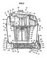
- Figure 2is a section view of the vacuum of Fig. 1 taken along line 2-2 in Fig. 1 .
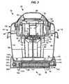
- Figure 3is a section view of the vacuum of Fig. 1 taken along line 3-3 in Fig. 1 .
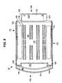
- Figure 4is an exploded view of the base of the vacuum, including the battery pack.
- Figure 5is a perspective view of the battery pack.
- Figure 6is a left side view of the battery pack.
- Figure 7is a right side view of the battery pack.
- Figure 8is a top side view of the battery pack.
- Figure 9is a bottom side view of the battery pack.
- Figure 10is a back side view of the battery pack.
- Figure 11is a front side view of the battery pack.
- Figure 12is a perspective view of the battery pack with the cover removed.
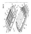
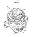
- Fig. 13is a perspective view of the vacuum cleaner of Fig. 1 with the battery pack detached.
- Figure 14is a perspective view of the battery pack mounted to a charging station.
- Figure 15is a perspective view of a second example of a vacuum cleaner.
- Figure 16is a perspective view of the motor assembly and battery pack detached from the vacuum cleaner of Fig. 15 .
- Figure 17is a perspective view of the motor assembly and battery pack detached from the vacuum cleaner of Fig. 15 with a second motor assembly attached to the vacuum cleaner.
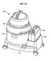
- Figure 18is a perspective view of a third example of a vacuum cleaner.
- the vacuum cleaner 10has a front side 12, a back side 14, a left side 16, a right side 18, a top side 20, and a bottom side 22. These labels are for convenience of description only, and no limitation shall be read therein.
- the vacuum cleaner 10includes a base 24, a receiving tank 26 disposed on the base 24, and a lid assembly 28 disposed on the receiving tank 26 that includes a cover 30. Casters or wheels (not depicted) may be attached to the base 24 to make the vacuum cleaner 10 easier to move.
- the vacuum cleaner 10further includes a motor assembly 32 disposed in the lid assembly 28 and under the cover 30, and a battery pack 34 releasably disposed in the base 24.
- the motor assembly 32 and the battery pack 34define at least a portion of a blower assembly 36.
- the tank 26includes a bottom wall 38 and a side wall 40 extending up from the bottom wall 36.
- a series of bosses 42can extend up from the bottom wall 38 to accommodate the attachment of the base 24 to the tank 26 as will be described later.
- the side wall 40is generally circular, but other shapes can be used, such as a side wall 40 that is rectangular with four panels.
- the tank 26 as showndefines an interior volume of 2.5 gallons, but any useful size can be employed.
- Disposed in the side wall 40is an inlet 44.
- the inlet 44is an opening in the side wall 40 to which a hose (not shown) can be attached.
- the hosecan be used, as is known, to direct the debris into the tank 26 when the motor is running.
- the top of the side wall 40defines a rim 46.
- the tank 26has an inner surface 48 defined in part by a bottom inner surface 50.
- the bottom inner surface 50is defined as the part of the tank 26 against which the debris or liquid gathered into the tank 26 by the vacuum 10 settles due to the force of gravity.
- a majority of the bottom inner surface 50is defined by the bottom wall 38, however, in other examples, a portion of the bottom inner surface 50 may be defined by caster supports, rims, legs or other structure.
- the lid assembly 28is disposed on the rim 46 of the tank 26.
- the lid assembly 28includes a lid 52 that is constructed to attach the motor assembly 32 to the lid assembly.28.
- the lid 52may be formed integrally with a filter cage 54 that extends down into the tank 26.
- a filter 56is placed on the filter cage 54 to ensure that debris pulled into the tank 26 through the hose is maintained in the tank 26, and no debris, i.e. only air, flows into and through the motor assembly 32.
- a variety of filter typescan be used, including foam, cartridge filters and cloth disks.
- the motor assembly 32disposed on the lid 52, includes a lower motor housing 58 and a grid plate 60 spaced downward from the lower motor housing 58.
- An upper motor housing 59is located above the motor but under the cover 30.
- An impeller chamber 62is disposed in the space between the lower motor housing 58 and the grid plate 60.
- the grid plate 60includes an outer edge 64 which is radially outward from the lower motor housing 58.
- Sidewalls 66extend upward from the outer edge 64 radially outward from the motor housing 58.
- the space between the sidewalls 66 and the motor housing 58defines an annular chamber 68.
- the lower motor housing 58can be disposed on the motor mount 52 using any construction known in the art.
- the motor assembly 32is relatively permanently fixed to the rest of the lid assembly 28.
- a detachable blowercan be used to create a vacuum within the tank 26 and also be removed to be used as a hand held blower or vacuum as more fully described below.
- a DC motor 70is maintained within the motor housing 58. While a DC motor 70 is shown, a universal type motor can also be used.
- a shaft 72extends down from the motor 70, and out of the motor housing 58 through an aperture 74 in the housing 58.
- An impeller 76is disposed on the end of the shaft 72 in the impeller chamber 62.
- the grid plate 60includes a grated portion 78, such that air can pass freely from outside the motor assembly 32 through the grated portion 78 and into the impeller chamber 62.
- the lid assembly 28 and the cover 30define a blower chamber 80 on the back side 16 of the vacuum cleaner 10.
- the blower chamber 80receives air that has been discharged by the impeller 76.
- the aircan then be directed out slots 82 in the lid 24 on the back side 14 (shown in Fig. 1 ).
- Vents 84 in the cover 30 on the top side 20 of the vacuum cleaner 10are provided for the intake and exhaust of cooling air for the motor 70 or can also provide exhaust for the working air from the air impeller 76.
- the aircan escape out a port 86 in either the lid 24 or the cover 30 on the back side 14.
- a hosecan be attached to the port 86 such that the vacuum cleaner 10 can direct a stream of air and function as a blower.
- the lid assembly 28includes at least one handle 88 that can be used to lift and carry the vacuum cleaner 10.
- An on/off switch 90is disposed on the lid assembly 28 and a power cord 92 extends at a first end from the motor assembly 32 to a plug 94 at a second end.
- the DC motor 70 and the battery pack 34are in electrical communication, and the on/off switch selectively allows current to flow from the battery pack 34 to the motor 70 and to cut any supply of current to the motor 70, i.e. to turn the DC motor 70 on and off and thus the vacuum 10 on and off.
- the power cord 92can be sized to a length such that there is a relatively small amount of slack in the power cord 92 between the motor assembly 32 and the battery pack 34.
- the power cord 92can also be coiled to take up any slack.
- the tank 26can include recesses (not shown) within which the power cord 92 can be secured.
- the base 24is disposed under the tank 26 and supports the tank 26 in an elevated condition when the base 24 is placed on a floor or other substrate.
- the base 24includes a dolly 100, the battery pack 34, and a battery tray 102.
- the dolly 100 and the battery tray 102combine to locate and support the battery pack 32 at the bottom side 22 of the vacuum cleaner 10.
- the dolly 100includes an outer wall 104 that can be generally circular and will usually have a similar shape and size as the side wall 40 of the tank 24.
- the outer wall 104has a top edge 106 and a bottom edge 108.
- a bowl section 110is disposed inside the outer wall 104 and connected to the outer wall 104 at the top edge 106.
- the bowl section 110includes a ramped portion 112 and a bottom wall 114. The ramped portion 112 and the bottom wall 114 of the dolly 100 can be constructed to engage and support the bottom wall 38 of the tank 26.
- the bottom wall 114 of the dolly 100can include holes 116 that are coaxial with the holes 42 of the bottom wall 38 of the tank 26 such that fasteners may be inserted through the holes 116 and into bosses 42 to fasten the base 24 to the tank 26.
- Other methods of permanent or releasable connectionsuch as welding, bonding, a snap fit, or the like, can be implemented.
- the dolly 100includes an opening 118 in the outer wall 104 that is sized and shaped to receive the battery pack 34.
- the dolly 100includes a lip 120 extending outward from the outer wall 104 that defines the opening 118.
- the dolly 100also includes an outlet housing 122 extending outward from the outer wall 104 and includes an outlet receptacle 124 that opens toward the top side 20 of the vacuum cleaner 10.
- the outlet receptacle 124is sized and shaped to releasably receive the outlet 126.
- the outlet receptacle 124can include a detent 128 to securely locate and maintain the outlet 126 (seen best in Fig. 2 ).
- the dolly 100includes a plurality of posts 130 extending downward to the bottom side 22 of the vacuum 10.
- the plug 94is removable from the outlet 126 such that when the lid assembly 28 and motor assembly 32 is removed from the tank 26, for instance in order to empty the tank 26 of debris, the power cord 92 can be unplugged and the combination can be completely detached from the tank 26.
- the battery tray 102includes a plurality of tubes 132 sized and shaped to receive the posts 130 of the dolly 100.
- the tubes 132can fasten the battery tray 102 to the dolly 100 via a snap fit or other connection between the tubes 132 and the posts 130.
- the tubes 132also include a footing 134.
- the footing 134can bear on the substrate on which the vacuum cleaner 10 is placed or be used for connection to casters or wheels.
- the battery tray 102includes a bottom wall 136 and two side walls 138 to which the tubes 132 are connected.
- the bottom wall 136 and the two sidewalls 138 of the battery tray 102 and the bottom wall 114 of the dolly 100combine to form a chamber 140 into which the battery pack 34 is disposed.
- Rails 142can be placed on the bottom wall 136 of the battery tray 102 to help guide the battery pack 34 into the chamber 140.
- the battery tray 102can include an outlet chamber 142 that is sized and shaped to coordinate with the outlet receiver 122 of the dolly 100 when the battery tray 102 is fastened to the dolly 100.
- the outlet chamber 142can mount and protect the outlet 126.
- the tubes 132are connected to the sidewalls 138, and the outlet chamber 142 is disposed adjacent a sidewall 138, however, other configurations are possible.
- An electrical connector assembly 144is maintained in between the battery tray 102 and the dolly 100.
- the connector assembly 144is fastened to the bottom wall 136 of the battery tray 102, however, other methods of attachment may be used.
- the connector assembly 144includes an insulating block 146, and a positive terminal 148 and a negative terminal 150 both extending from the insulating block 146.
- a first positive wire 152 and a first negative wire 154are connected to the positive terminal 148 and the negative terminal 150, respectively.
- the conductor assembly 144further includes the outlet 126.
- a second positive wire 156 and a second negative wire 158are connected to the outlet 126.
- first positive wire 152 and the second positive wire 156are connected, and the first negative wire 154 and the second negative wire 158 are connected. Both connections are made at a terminal block 160.
- the wirescan also be joined by wire nuts or other structure or methods. In another example, only a single positive wire and a single negative wire connects the positive and negative terminals 148, 150 to the outlet 126.
- the battery pack 34includes a top side 162, a bottom side 164, a front side 166, a back side 168, a left side 170, and a right side 172.
- the battery pack 34includes a handle 174, a battery housing indicated generally at numeral 176, and a battery connector assembly 178.
- the handle 174 and the battery housing 176are connected by extensions 180.
- a finger space 182is disposed in between the handle 174 and the battery housing 176.
- the housing 176includes a top face 184 on the top side 162 and a bottom face 186 on the bottom side 164.
- a series of channels 188are disposed on the top face 184 and the bottom face 186 of the housing 176.
- the channels 188increase the surface area of the battery pack 34 to aid in heat transfer from the battery pack 34 to the atmosphere.
- the channels 188also serve to increase the rigidity of the housing 176, and further can help locate the batteries within the battery pack 34.
- slots 190can be disposed in the channels 188 such that air may circulate from inside the battery pack 34 to outside of the battery pack 34. This circulation would further aid in heat removal from inside the battery pack 34.
- the slotscould be disposed either in the sides of the channels 188 or the base of the channels 188.
- first guideway 192At the intersection of the left side 170 and the top surface 184 is a first guideway 192. Further, at the intersection of the right side 172 and the top surface 184 is a second guideway 194.
- the first and second guideways 192, 194engage guides in the dolly 100 while the battery pack 34 is being inserted into the chamber 140 to help guide the battery pack 34 into the chamber 140.
- a first detent 196 and a second detent 198are disposed forward of the first guideway 192 and the second guideway 194, respectively.
- the detents 196, 198can engage structure in the dolly 100 or the battery tray 102 such as spring loaded tabs (not depicted) to releasably secure the battery pack 34 in the chamber 140.
- the outer dimensions of the battery pack 34can be only slightly less than the inner dimensions of the chamber 140 to ensure a snug fit.
- the battery pack 34can be maintained in the chamber 140 by any other means known in the art.
- the handle 174 of the battery pack 34is disposed at the front side 166 and has a top surface 200 on the top side 162 and a bottom surface 202 on the bottom side 164.
- the top surface 200 of the handle 174is in stepped relation to the top surface 184 of the housing 176
- the bottom surface 202 of the handle 174is in stepped relation to the bottom surface 184 of the housing 176.
- the stepped relation of the handle 174 to the housing 176allows for the handle 174 to substantially seal against the opening 118 in the outer wall 104 of the dolly 100 to provide a continuous, attractive appearance. It also allows a space for the user's fingers to reach underneath the handle 174 to grasp the battery pack 34 while inserting or removing the battery pack 34 from the chamber 140.
- the front side 166 of the battery pack 34can be curved to generally match the outer wall of the dolly 100.
- the battery connector assembly 178 extending outward from the back sideincludes opposing top and bottom walls 204, 206, and opposing left side and right side walls 208, 210.
- the right side wall 210is curved, and the left side wall 208 is straight. The curvature of the right side wall 210 ensures that the battery pack 34 is inserted correctly into a charger, as will be seen.
- a series of slots 212are disposed in the connector assembly 178 on the back side 168.
- the left most and right most slot 212a, 212bare adapted to receive the positive and negative terminals 148, 150 of the conductor assembly 144.
- the remaining slots 212have functionality that will be described herein.
- the connector assembly 178includes a series of divider walls 214 that create separate chambers 216 in the connector assembly 178, with one slot 212 correlated to each chamber 216.
- a set of prong terminals 218are disposed near the back side 168.
- Each prong terminal 218includes a pair of prongs 220 extending to the back side 168 from the housing 176 into a respective chamber 216 and to a position adjacent a slot 212.
- the battery pack 34Inside the battery pack 34 is a plurality of batteries 222 in electrical connection.
- five rows of four batteries 22are maintained in an electrical series with the prong terminal on the far left side, or left prong terminal 220a, and the prong terminal on the far right side, or right prong terminal 220b.
- the right prong terminal 220bis a positive terminal in this example, while the left prong terminal 220a is a negative terminal.
- the series connectionis set up in standard fashion, with the negative side of the batteries 222 in direct contact with the positive side of the adjacent batteries 222, or the negative side of the batteries 222 connected to the positive side of the batteries 222 using an electrically conductive material.
- the battery pack 34can maintain a voltage of 18 or 24 VDC, however, other voltages can easily be achieved by changing the number of batteries 222 or the voltage of each of the individual batteries 222.
- the battery pack 34also includes three center prong terminals 220b, 220c, 220d that are not used to conduct electricity. Instead, these prong terminals can be used to transmit information during the charging process, as will be described later.
- the chamber 140is formed by the dolly 100 and the battery tray 102, however, other constructions can be used to releasably store the battery pack 34 and maintain the battery pack 34 with the tank 26.
- Thisincludes a pair of rails, the use of magnetics, clips, cords, or any other structure known to releasably store an item.
- the battery pack 34could be stored in a chamber in the tank 26 itself, or any other part of the vacuum 10.
- the chamber 140 and battery pack 34are shown to be disposed underneath both the bottom inner surface 50 and the bottom wall 38 of the tank 26.
- the low placement of the battery pack 34helps to maintain a low center of gravity for the vacuum 10, thus making the vacuum 10 more stable.
- the battery pack 34could also be releasably located on the sidewall 42 of the tank 26. In this manner, the battery pack 34 would be more easily accessible for recharging and removal, but it would create a larger footprint for the vacuum 10. This construction would further raise the center of gravity and also pull the center of gravity away from the center of the tank 26. Thus, the vacuum 10 would be less stable as it is moved.
- the battery pack 34can be removed from and installed to the vacuum 10 simply by moving the battery pack 34 in the direction of arrow D1 through the dolly lip 120 and into and out of the chamber 140.
- a charging station 224can be used to recharge the battery pack 34.
- the charging station 224can be plugged into any standard electrical outlet using cord 226 and can convert 120V AC power to 18 or 24 VDC power.
- the charging station 224can include a plurality of ports (not shown) adapted to receive the prong terminals 218 of the battery pack 34. By inserting the prong terminals 218 into the ports, the charging station 224 can perform a quick-charge recharging of the battery pack 34.
- the center prongs 220c, 220d, 220ecan provide information to the charging station 224 such as temperature to ensure that the quick charge is performed without damaging the batteries 222.
- batteries 22may also be used. These include disposing a power converter within the battery pack 34 or elsewhere on the vacuum cleaner 10, so that the battery pack 34 and/or the vacuum cleaner 10 can be directly connected to a standard electrical outlet. A/C power supplied to the converter is converted to DC power and supplied to the battery pack 34.
- the battery pack 34will generally store the DC power, but it can supply the DC power directly to the motor assembly 32. In this manner, if the battery power is low, the vacuum cleaner 10 can be plugged into an outlet and the battery power supplied to the battery pack 34 is immediately provided to the motor assembly 32.
- the batteries 222 within the battery pack 34can be made from any known materials or hereafter discovered materials that are capable of rechargably storing DC power. This includes Ni-Cd, Lithium, etc. Further, a non-rechargeable battery could also be used, but would be less desireable for this type of application.
- the lid assembly 28is disposed on the tank 26 to create at least a relatively air-tight seal.
- the motor 70is energized and rotates the shaft 72, which rotates the impeller 76.
- a pressure differentialis created across the impeller 76 due to its rotation, and air is pulled from the atmosphere and into the interior of the tank 26 through the inlet 44.
- the airthen flows through the filter 56 and any debris is trapped inside the tank 22.
- the airthen moves through the grid plate 60, across the impeller 76 in the impeller chamber 62 and is pushed out the outer perimeter of the impeller 76 to the annular chamber 68 and into the blower chamber 80.
- the aircan be directed out to the atmosphere in any of the previously mentioned structures, i.e. slots 82, a port 86, vents 84, or other structures known in the art. Details of a similar air flow through the housing are shown in U.S. Patent No. 6,530,116 , which is incorporated herein by reference.
- the vacuum 10may be transported anywhere free of the encumbrance of a cord connected to an outlet on the wall. Once the power is drained from the battery pack 34, the battery pack 34 can be removed from the vacuum 10 and placed in the charging station 224 to recharge the batteries 222. After recharging is complete, the battery pack 34 may be inserted back into the chamber 140 into contact with the conductor assembly 144 to provide power to the motor assembly 32.
- the use of a detachable rechargeable battery pack 34 in conjunction with the motor assembly 32provides several benefits.
- the vacuum 10is self-contained, and can be placed and used anywhere on a shop floor or outside irrespective of power outlets. No power cords limit the travel of the vacuum 10.
- the vacuum 10does not rely on a gas powered motor assembly, which can be extremely loud indoors.
- the entire vacuum 10is physically stabilized.
- the center of gravity of the vacuum 10is lowered due to the concentrated weight of the battery pack 34 near the bottom of the vacuum 10 so that it is less prone to tipping.
- the tankcan have a capacity of 2.5 gallons, which is comparatively small and easy to carry relative to current vacuums designed for shop floor environments. Because it is small and battery powered, it is easily transportable by hand to any location that may need cleaning without consideration of an electrical wall outlet. The utility of the vacuum is therefore greatly enhanced.
- FIG. 15A second example of a vacuum cleaner 250 is depicted in Figs. 15 , 16 , and 17 .
- a battery 252 and a motor assembly 254may be removed from the vacuum cleaner 250 to form a portable blower assembly 256.
- a tube 258can be attached to the motor assembly 254 to provide a directed airflow out of the motor assembly 254. Details of a typical vacuum cleaner with a detachable blower are shown in U.S. Patent No. 6,530,116 , which is incorporated by reference herein.
- the motor assembly 254includes a cord 260 with a plug 262.
- the plug 262is disposed in an outlet 264 that is mounted in the battery 252.
- the battery 252can include a strap 266 to improve its transportability.
- a second motor assembly 268may be mounted to the vacuum cleaner 250 ( Fig. 17 ).
- the second motor assembly 268can be directly plugged into a standard electrical wall outlet.
- the first motor assembly 254can be powered by direct current
- the second motor assembly 268can be powered by alternating current.
- FIG 18is a perspective view of a third example of a vacuum cleaner 270.
- the vacuum cleaner 270includes a tank 272 disposed on a base 274.
- the base 274extends out from the tank 272 and includes a mounting station 276 and a tool mount 277 that may receive any number of tools, including brushes, brooms, and the like.
- the mounting station 276is designed such that a battery 278 may be inserted into the mounting station 276 in a downward manner.
- the mounting station 276may include structure as depicted and described in reference to the first example such that power from the battery 278 is transferred to a motor assembly (not shown).
- the insertion of the battery 278is aided by gravity, and is mounted at a comparatively higher elevation.
- the footprintis enlarged and the benefits of the first example with respect to the stability of the unit are not as great.
Landscapes
- Engineering & Computer Science (AREA)
- Mechanical Engineering (AREA)
- Robotics (AREA)
- Electric Vacuum Cleaner (AREA)
- Electric Suction Cleaners (AREA)
- Battery Mounting, Suspending (AREA)
- Secondary Cells (AREA)
Abstract
Description
- The present disclosure relates to a vacuum apparatus, and more specifically, to a vacuum with a rechargeable battery.
- This application claims priority to
U.S. Provisional Application No. 60/527,874, filed on December 8, 2003 U.S. Provisional Application No. 60/546,159, filed on February 20, 2004 - Vacuum cleaners for industrial environments and outdoor use generally include a holding tank on top of which is disposed a motor assembly. An air inlet can be disposed in the side of the tank with a hose connected to the air inlet. The motor assembly includes a housing inside of which is disposed an electric motor connected to an air impeller. When energized, the electric motor spins the impeller to create a low pressure area within the tank. Air is drawn into the tank through the hose and inlet in the side of the tank and up to the impeller. The air is then pushed through the motor housing and exhausted to the atmosphere. Debris pulled into the tank through the hose is kept inside the tank by placing a filter between the motor assembly and the tank.
- The electric motor is usually an AC motor that is supplied current by a cord plugged into a standard electrical outlet. The cord provides a generally constant source of electric current. However, the user is limited in the area that can be vacuumed by the length of the cord. Further, the cord can be unwieldy and must be maintained with the vacuum. The longer the cord, the more unwieldy it is. Thus, the manufacturer must balance the needs for a large range of use with the impracticalities of having a long cord.
The documentFR-A-2 690 328 US-B1-6 553 612 of a vacuum cleaner with a removable battery pack. Figure 1 is a perspective view of a vacuum cleaner that includes a motor assembly and a detachable battery pack.Figure 2 is a section view of the vacuum ofFig. 1 taken along line 2-2 inFig. 1 .Figure 3 is a section view of the vacuum ofFig. 1 taken along line 3-3 inFig. 1 .Figure 4 is an exploded view of the base of the vacuum, including the battery pack.Figure 5 is a perspective view of the battery pack.Figure 6 is a left side view of the battery pack.Figure 7 is a right side view of the battery pack.Figure 8 is a top side view of the battery pack.Figure 9 is a bottom side view of the battery pack.Figure 10 is a back side view of the battery pack.Figure 11 is a front side view of the battery pack.Figure 12 is a perspective view of the battery pack with the cover removed.Fig. 13 is a perspective view of the vacuum cleaner ofFig. 1 with the battery pack detached.Figure 14 is a perspective view of the battery pack mounted to a charging station.Figure 15 is a perspective view of a second example of a vacuum cleaner.Figure 16 is a perspective view of the motor assembly and battery pack detached from the vacuum cleaner ofFig. 15 .Figure 17 is a perspective view of the motor assembly and battery pack detached from the vacuum cleaner ofFig. 15 with a second motor assembly attached to the vacuum cleaner.Figure 18 is a perspective view of a third example of a vacuum cleaner.- While the disclosure is susceptible to various modifications and alternative constructions, certain illustrative embodiments thereof have been shown in the drawings and will be described below in detail. It should be understood, however, that there is no intention to limit the disclosure to the specific forms disclosed, but on the contrary, the intention is to cover all modifications, alternative constructions, and the equivalents falling within the scope of the invention as defined by the appended claims.
- Referring now to the drawings, and in particular to
Figs. 1 and2 , avacuum cleaner 10 is depicted. Thevacuum cleaner 10 has afront side 12, aback side 14, aleft side 16, aright side 18, atop side 20, and abottom side 22. These labels are for convenience of description only, and no limitation shall be read therein. Thevacuum cleaner 10 includes abase 24, areceiving tank 26 disposed on thebase 24, and alid assembly 28 disposed on the receivingtank 26 that includes acover 30. Casters or wheels (not depicted) may be attached to thebase 24 to make thevacuum cleaner 10 easier to move. Thevacuum cleaner 10 further includes amotor assembly 32 disposed in thelid assembly 28 and under thecover 30, and abattery pack 34 releasably disposed in thebase 24. Themotor assembly 32 and thebattery pack 34 define at least a portion of ablower assembly 36. - Referring now to
Figs. 2 and3 , thetank 26 includes abottom wall 38 and aside wall 40 extending up from thebottom wall 36. A series ofbosses 42 can extend up from thebottom wall 38 to accommodate the attachment of thebase 24 to thetank 26 as will be described later. In this example, theside wall 40 is generally circular, but other shapes can be used, such as aside wall 40 that is rectangular with four panels. Thetank 26 as shown defines an interior volume of 2.5 gallons, but any useful size can be employed. Disposed in theside wall 40 is aninlet 44. Theinlet 44 is an opening in theside wall 40 to which a hose (not shown) can be attached. The hose can be used, as is known, to direct the debris into thetank 26 when the motor is running. The top of theside wall 40 defines arim 46. - The
tank 26 has aninner surface 48 defined in part by a bottominner surface 50. The bottominner surface 50 is defined as the part of thetank 26 against which the debris or liquid gathered into thetank 26 by thevacuum 10 settles due to the force of gravity. In the example shown inFig. 2 , a majority of the bottominner surface 50 is defined by thebottom wall 38, however, in other examples, a portion of the bottominner surface 50 may be defined by caster supports, rims, legs or other structure. - The
lid assembly 28 is disposed on therim 46 of thetank 26. Thelid assembly 28 includes alid 52 that is constructed to attach themotor assembly 32 to the lid assembly.28. Thelid 52 may be formed integrally with afilter cage 54 that extends down into thetank 26. Afilter 56 is placed on thefilter cage 54 to ensure that debris pulled into thetank 26 through the hose is maintained in thetank 26, and no debris, i.e. only air, flows into and through themotor assembly 32. A variety of filter types can be used, including foam, cartridge filters and cloth disks. - The
motor assembly 32, disposed on thelid 52, includes alower motor housing 58 and agrid plate 60 spaced downward from thelower motor housing 58. Anupper motor housing 59 is located above the motor but under thecover 30. Animpeller chamber 62 is disposed in the space between thelower motor housing 58 and thegrid plate 60. Thegrid plate 60 includes anouter edge 64 which is radially outward from thelower motor housing 58.Sidewalls 66 extend upward from theouter edge 64 radially outward from themotor housing 58. The space between the sidewalls 66 and themotor housing 58 defines anannular chamber 68. - The
lower motor housing 58 can be disposed on themotor mount 52 using any construction known in the art. In the embodiment shown inFigs. 1-13 , themotor assembly 32 is relatively permanently fixed to the rest of thelid assembly 28. However, as is known in the art, a detachable blower can be used to create a vacuum within thetank 26 and also be removed to be used as a hand held blower or vacuum as more fully described below. ADC motor 70 is maintained within themotor housing 58. While aDC motor 70 is shown, a universal type motor can also be used. Ashaft 72 extends down from themotor 70, and out of themotor housing 58 through anaperture 74 in thehousing 58. Animpeller 76 is disposed on the end of theshaft 72 in theimpeller chamber 62. Thegrid plate 60 includes a gratedportion 78, such that air can pass freely from outside themotor assembly 32 through the gratedportion 78 and into theimpeller chamber 62. - The
lid assembly 28 and thecover 30 define ablower chamber 80 on theback side 16 of thevacuum cleaner 10. Theblower chamber 80 receives air that has been discharged by theimpeller 76. The air can then be directed outslots 82 in thelid 24 on the back side 14 (shown inFig. 1 ).Vents 84 in thecover 30 on thetop side 20 of thevacuum cleaner 10 are provided for the intake and exhaust of cooling air for themotor 70 or can also provide exhaust for the working air from theair impeller 76. In a still further design, the air can escape out aport 86 in either thelid 24 or thecover 30 on theback side 14. In this design, a hose can be attached to theport 86 such that thevacuum cleaner 10 can direct a stream of air and function as a blower. - The
lid assembly 28 includes at least onehandle 88 that can be used to lift and carry thevacuum cleaner 10. An on/offswitch 90 is disposed on thelid assembly 28 and apower cord 92 extends at a first end from themotor assembly 32 to aplug 94 at a second end. As will be described herein, theDC motor 70 and thebattery pack 34 are in electrical communication, and the on/off switch selectively allows current to flow from thebattery pack 34 to themotor 70 and to cut any supply of current to themotor 70, i.e. to turn theDC motor 70 on and off and thus thevacuum 10 on and off. Thepower cord 92 can be sized to a length such that there is a relatively small amount of slack in thepower cord 92 between themotor assembly 32 and thebattery pack 34. Thepower cord 92 can also be coiled to take up any slack. Thetank 26 can include recesses (not shown) within which thepower cord 92 can be secured. - Referring now to
Figs. 1 and4 , thebase 24 is disposed under thetank 26 and supports thetank 26 in an elevated condition when thebase 24 is placed on a floor or other substrate. Thebase 24 includes adolly 100, thebattery pack 34, and abattery tray 102. Thedolly 100 and thebattery tray 102 combine to locate and support thebattery pack 32 at thebottom side 22 of thevacuum cleaner 10. - The
dolly 100 includes anouter wall 104 that can be generally circular and will usually have a similar shape and size as theside wall 40 of thetank 24. Theouter wall 104 has atop edge 106 and abottom edge 108. Abowl section 110 is disposed inside theouter wall 104 and connected to theouter wall 104 at thetop edge 106. Thebowl section 110 includes a rampedportion 112 and abottom wall 114. The rampedportion 112 and thebottom wall 114 of thedolly 100 can be constructed to engage and support thebottom wall 38 of thetank 26. Thebottom wall 114 of thedolly 100 can includeholes 116 that are coaxial with theholes 42 of thebottom wall 38 of thetank 26 such that fasteners may be inserted through theholes 116 and intobosses 42 to fasten the base 24 to thetank 26. Other methods of permanent or releasable connection, such as welding, bonding, a snap fit, or the like, can be implemented. - The
dolly 100 includes anopening 118 in theouter wall 104 that is sized and shaped to receive thebattery pack 34. In this example, thedolly 100 includes alip 120 extending outward from theouter wall 104 that defines theopening 118. Thedolly 100 also includes anoutlet housing 122 extending outward from theouter wall 104 and includes anoutlet receptacle 124 that opens toward thetop side 20 of thevacuum cleaner 10. Theoutlet receptacle 124 is sized and shaped to releasably receive theoutlet 126. Theoutlet receptacle 124 can include adetent 128 to securely locate and maintain the outlet 126 (seen best inFig. 2 ). Thedolly 100 includes a plurality ofposts 130 extending downward to thebottom side 22 of thevacuum 10. Theplug 94 is removable from theoutlet 126 such that when thelid assembly 28 andmotor assembly 32 is removed from thetank 26, for instance in order to empty thetank 26 of debris, thepower cord 92 can be unplugged and the combination can be completely detached from thetank 26. - The
battery tray 102 includes a plurality oftubes 132 sized and shaped to receive theposts 130 of thedolly 100. Thetubes 132 can fasten thebattery tray 102 to thedolly 100 via a snap fit or other connection between thetubes 132 and theposts 130. Thetubes 132 also include afooting 134. Thefooting 134 can bear on the substrate on which thevacuum cleaner 10 is placed or be used for connection to casters or wheels. - The
battery tray 102 includes abottom wall 136 and twoside walls 138 to which thetubes 132 are connected. Thebottom wall 136 and the twosidewalls 138 of thebattery tray 102 and thebottom wall 114 of thedolly 100 combine to form achamber 140 into which thebattery pack 34 is disposed.Rails 142 can be placed on thebottom wall 136 of thebattery tray 102 to help guide thebattery pack 34 into thechamber 140. - The
battery tray 102 can include anoutlet chamber 142 that is sized and shaped to coordinate with theoutlet receiver 122 of thedolly 100 when thebattery tray 102 is fastened to thedolly 100. Theoutlet chamber 142 can mount and protect theoutlet 126. In this example, thetubes 132 are connected to thesidewalls 138, and theoutlet chamber 142 is disposed adjacent asidewall 138, however, other configurations are possible. - An
electrical connector assembly 144 is maintained in between thebattery tray 102 and thedolly 100. In this example, theconnector assembly 144 is fastened to thebottom wall 136 of thebattery tray 102, however, other methods of attachment may be used. Theconnector assembly 144 includes an insulatingblock 146, and a positive terminal 148 and anegative terminal 150 both extending from the insulatingblock 146. A firstpositive wire 152 and a firstnegative wire 154 are connected to the positive terminal 148 and thenegative terminal 150, respectively. Theconductor assembly 144 further includes theoutlet 126. A secondpositive wire 156 and a secondnegative wire 158 are connected to theoutlet 126. In this example, the firstpositive wire 152 and the secondpositive wire 156 are connected, and the firstnegative wire 154 and the secondnegative wire 158 are connected. Both connections are made at aterminal block 160. The wires can also be joined by wire nuts or other structure or methods. In another example, only a single positive wire and a single negative wire connects the positive andnegative terminals 148, 150 to theoutlet 126. - Referring now to
Figs. 5-11 , thebattery pack 34 includes atop side 162, abottom side 164, afront side 166, aback side 168, aleft side 170, and aright side 172. Thebattery pack 34 includes ahandle 174, a battery housing indicated generally atnumeral 176, and abattery connector assembly 178. Thehandle 174 and thebattery housing 176 are connected byextensions 180. Afinger space 182 is disposed in between thehandle 174 and thebattery housing 176. - The
housing 176 includes atop face 184 on thetop side 162 and abottom face 186 on thebottom side 164. A series ofchannels 188 are disposed on thetop face 184 and thebottom face 186 of thehousing 176. Thechannels 188 increase the surface area of thebattery pack 34 to aid in heat transfer from thebattery pack 34 to the atmosphere. Thechannels 188 also serve to increase the rigidity of thehousing 176, and further can help locate the batteries within thebattery pack 34. In one example not shown,slots 190 can be disposed in thechannels 188 such that air may circulate from inside thebattery pack 34 to outside of thebattery pack 34. This circulation would further aid in heat removal from inside thebattery pack 34. The slots could be disposed either in the sides of thechannels 188 or the base of thechannels 188. - At the intersection of the
left side 170 and thetop surface 184 is afirst guideway 192. Further, at the intersection of theright side 172 and thetop surface 184 is asecond guideway 194. The first andsecond guideways dolly 100 while thebattery pack 34 is being inserted into thechamber 140 to help guide thebattery pack 34 into thechamber 140. Afirst detent 196 and asecond detent 198 are disposed forward of thefirst guideway 192 and thesecond guideway 194, respectively. Thedetents dolly 100 or thebattery tray 102 such as spring loaded tabs (not depicted) to releasably secure thebattery pack 34 in thechamber 140. The outer dimensions of thebattery pack 34 can be only slightly less than the inner dimensions of thechamber 140 to ensure a snug fit. Thebattery pack 34 can be maintained in thechamber 140 by any other means known in the art. - The
handle 174 of thebattery pack 34 is disposed at thefront side 166 and has atop surface 200 on thetop side 162 and abottom surface 202 on thebottom side 164. Thetop surface 200 of thehandle 174 is in stepped relation to thetop surface 184 of thehousing 176, and thebottom surface 202 of thehandle 174 is in stepped relation to thebottom surface 184 of thehousing 176. The stepped relation of thehandle 174 to thehousing 176 allows for thehandle 174 to substantially seal against theopening 118 in theouter wall 104 of thedolly 100 to provide a continuous, attractive appearance. It also allows a space for the user's fingers to reach underneath thehandle 174 to grasp thebattery pack 34 while inserting or removing thebattery pack 34 from thechamber 140. Thefront side 166 of thebattery pack 34 can be curved to generally match the outer wall of thedolly 100. - The
battery connector assembly 178 extending outward from the back side includes opposing top andbottom walls right side walls right side wall 210 is curved, and theleft side wall 208 is straight. The curvature of theright side wall 210 ensures that thebattery pack 34 is inserted correctly into a charger, as will be seen. A series ofslots 212 are disposed in theconnector assembly 178 on theback side 168. The left most and rightmost slot negative terminals 148, 150 of theconductor assembly 144. The remainingslots 212 have functionality that will be described herein. - Referring now to
Fig. 12 , a view of thebattery pack 34 with its top removed is depicted. Theconnector assembly 178 includes a series ofdivider walls 214 that createseparate chambers 216 in theconnector assembly 178, with oneslot 212 correlated to eachchamber 216. A set ofprong terminals 218 are disposed near theback side 168. Eachprong terminal 218 includes a pair ofprongs 220 extending to theback side 168 from thehousing 176 into arespective chamber 216 and to a position adjacent aslot 212. - Inside the
battery pack 34 is a plurality ofbatteries 222 in electrical connection. In this example, five rows of fourbatteries 22 are maintained in an electrical series with the prong terminal on the far left side, or leftprong terminal 220a, and the prong terminal on the far right side, orright prong terminal 220b. Theright prong terminal 220b is a positive terminal in this example, while theleft prong terminal 220a is a negative terminal. The series connection is set up in standard fashion, with the negative side of thebatteries 222 in direct contact with the positive side of theadjacent batteries 222, or the negative side of thebatteries 222 connected to the positive side of thebatteries 222 using an electrically conductive material. In this example, thebattery pack 34 can maintain a voltage of 18 or 24 VDC, however, other voltages can easily be achieved by changing the number ofbatteries 222 or the voltage of each of theindividual batteries 222. - The
battery pack 34 also includes threecenter prong terminals - In this example the
chamber 140 is formed by thedolly 100 and thebattery tray 102, however, other constructions can be used to releasably store thebattery pack 34 and maintain thebattery pack 34 with thetank 26. This includes a pair of rails, the use of magnetics, clips, cords, or any other structure known to releasably store an item. Further, thebattery pack 34 could be stored in a chamber in thetank 26 itself, or any other part of thevacuum 10. - In this example, a majority of, and in fact the entirety of, the
chamber 140 andbattery pack 34 are shown to be disposed underneath both the bottominner surface 50 and thebottom wall 38 of thetank 26. The low placement of thebattery pack 34, in combination with its relatively thin but wide design, helps to maintain a low center of gravity for thevacuum 10, thus making thevacuum 10 more stable. Thebattery pack 34 could also be releasably located on thesidewall 42 of thetank 26. In this manner, thebattery pack 34 would be more easily accessible for recharging and removal, but it would create a larger footprint for thevacuum 10. This construction would further raise the center of gravity and also pull the center of gravity away from the center of thetank 26. Thus, thevacuum 10 would be less stable as it is moved. - Referring to
Fig. 13 , thebattery pack 34 can be removed from and installed to thevacuum 10 simply by moving thebattery pack 34 in the direction of arrow D1 through thedolly lip 120 and into and out of thechamber 140. - Referring to
Fig. 14 , a chargingstation 224 can be used to recharge thebattery pack 34. The chargingstation 224 can be plugged into any standard electricaloutlet using cord 226 and can convert 120V AC power to 18 or 24 VDC power. The chargingstation 224 can include a plurality of ports (not shown) adapted to receive theprong terminals 218 of thebattery pack 34. By inserting theprong terminals 218 into the ports, the chargingstation 224 can perform a quick-charge recharging of thebattery pack 34. The center prongs 220c, 220d, 220e can provide information to the chargingstation 224 such as temperature to ensure that the quick charge is performed without damaging thebatteries 222. - Other alternatives for recharging the
batteries 22 may also be used. These include disposing a power converter within thebattery pack 34 or elsewhere on thevacuum cleaner 10, so that thebattery pack 34 and/or thevacuum cleaner 10 can be directly connected to a standard electrical outlet. A/C power supplied to the converter is converted to DC power and supplied to thebattery pack 34. Thebattery pack 34 will generally store the DC power, but it can supply the DC power directly to themotor assembly 32. In this manner, if the battery power is low, thevacuum cleaner 10 can be plugged into an outlet and the battery power supplied to thebattery pack 34 is immediately provided to themotor assembly 32. Thebatteries 222 within thebattery pack 34 can be made from any known materials or hereafter discovered materials that are capable of rechargably storing DC power. This includes Ni-Cd, Lithium, etc. Further, a non-rechargeable battery could also be used, but would be less desireable for this type of application. - In use of the
vacuum 10, thelid assembly 28 is disposed on thetank 26 to create at least a relatively air-tight seal. As is known, when the on/offswitch 90 is placed in the on position, themotor 70 is energized and rotates theshaft 72, which rotates theimpeller 76. A pressure differential is created across theimpeller 76 due to its rotation, and air is pulled from the atmosphere and into the interior of thetank 26 through theinlet 44. The air then flows through thefilter 56 and any debris is trapped inside thetank 22. The air then moves through thegrid plate 60, across theimpeller 76 in theimpeller chamber 62 and is pushed out the outer perimeter of theimpeller 76 to theannular chamber 68 and into theblower chamber 80. From theblower chamber 80, the air can be directed out to the atmosphere in any of the previously mentioned structures, i.e.slots 82, aport 86, vents 84, or other structures known in the art. Details of a similar air flow through the housing are shown inU.S. Patent No. 6,530,116 , which is incorporated herein by reference. Thevacuum 10 may be transported anywhere free of the encumbrance of a cord connected to an outlet on the wall. Once the power is drained from thebattery pack 34, thebattery pack 34 can be removed from thevacuum 10 and placed in the chargingstation 224 to recharge thebatteries 222. After recharging is complete, thebattery pack 34 may be inserted back into thechamber 140 into contact with theconductor assembly 144 to provide power to themotor assembly 32. - The use of a detachable
rechargeable battery pack 34 in conjunction with themotor assembly 32 provides several benefits. Thevacuum 10 is self-contained, and can be placed and used anywhere on a shop floor or outside irrespective of power outlets. No power cords limit the travel of thevacuum 10. Thevacuum 10 does not rely on a gas powered motor assembly, which can be extremely loud indoors. - If the
battery pack 34 is placed underneath the bottominner surface 50 of thetank 26, theentire vacuum 10 is physically stabilized. The center of gravity of thevacuum 10 is lowered due to the concentrated weight of thebattery pack 34 near the bottom of thevacuum 10 so that it is less prone to tipping. - In one example, the tank can have a capacity of 2.5 gallons, which is comparatively small and easy to carry relative to current vacuums designed for shop floor environments. Because it is small and battery powered, it is easily transportable by hand to any location that may need cleaning without consideration of an electrical wall outlet. The utility of the vacuum is therefore greatly enhanced.
- A second example of a
vacuum cleaner 250 is depicted inFigs. 15 ,16 , and17 . In this example, abattery 252 and amotor assembly 254 may be removed from thevacuum cleaner 250 to form aportable blower assembly 256. Atube 258 can be attached to themotor assembly 254 to provide a directed airflow out of themotor assembly 254. Details of a typical vacuum cleaner with a detachable blower are shown inU.S. Patent No. 6,530,116 , which is incorporated by reference herein. - In the depicted example, the
motor assembly 254 includes acord 260 with aplug 262. Theplug 262 is disposed in an outlet 264 that is mounted in thebattery 252. Thebattery 252 can include astrap 266 to improve its transportability. - When the
motor assembly 254 is removed from thevacuum cleaner 250, asecond motor assembly 268 may be mounted to the vacuum cleaner 250 (Fig. 17 ). In the shown example, thesecond motor assembly 268 can be directly plugged into a standard electrical wall outlet. Thus, thefirst motor assembly 254 can be powered by direct current, and thesecond motor assembly 268 can be powered by alternating current. Figure 18 is a perspective view of a third example of avacuum cleaner 270. Thevacuum cleaner 270 includes atank 272 disposed on abase 274. Thebase 274 extends out from thetank 272 and includes a mountingstation 276 and atool mount 277 that may receive any number of tools, including brushes, brooms, and the like.- The mounting
station 276 is designed such that abattery 278 may be inserted into the mountingstation 276 in a downward manner. The mountingstation 276 may include structure as depicted and described in reference to the first example such that power from thebattery 278 is transferred to a motor assembly (not shown). In this example, the insertion of thebattery 278 is aided by gravity, and is mounted at a comparatively higher elevation. However, the footprint is enlarged and the benefits of the first example with respect to the stability of the unit are not as great. - From the foregoing, one of ordinary skill in the art will appreciate that the present disclosure sets forth a battery powered vacuum cleaner that is convertible to a portable blower. However, one of ordinary skill in the art could readily apply the novel teachings of this disclosure to any number of situations. As such, the teachings of this disclosure shall not be considered to be limited to the specific examples disclosed herein, but to include all applications within the scope of the invention.
Claims (20)
- A vacuum cleaner (10) that has a motor assembly (32) that is adapted to draw debris into an inlet (44) in an adjacent tank (26), and a battery pack (34) that includes at least one battery (22) and supplies power to the motor assembly through a connection from the battery pack,characterized in that:the battery pack (34) is detachably disposed and slidably received in a tray (102) adjacent a bottom of the tank.
- The apparatus of claim 1, wherein at least one battery (22) of the battery pack (34) is rechargeable.
- The apparatus of claim 1, wherein the tank (26) defines a bottom inner surface (50) adapted to support the debris, wherein the battery pack (34) is detachably disposed under the bottom inner surface (50).
- The apparatus of claim 1, wherein the connection from the battery pack (34) to the motor assembly (32) includes a cord (92) at least in part connecting the battery pack (34) to the motor assembly (32).
- The apparatus of claim 1, further comprising a battery charger adapted to receive and recharge the battery.
- The apparatus of claim 1, further comprising a base (24) disposed under the tank (26) and supporting the tank, the battery being detachably disposed in the base.
- The apparatus of claim 6, the base further comprising a dolly (100) and the tray (102), the battery slidably received in the tray beneath the dolly.
- The apparatus of claim 6, further comprising a conductor assembly (144) mounted in the base and a cable extending from the conductor assembly to an outlet receptacle in the base and terminating in an outlet (126), the outlet being mounted in the outlet receptacle.
- The apparatus of claim 8, further comprising a second cord (92) with a first end extending from the motor assembly and terminating in a plug (94) at a second end, the plug being : releasably disposable in the outlet.
- The apparatus of claim 1, wherein the motor assembly (254) is releasable from the tank, and the battery pack (252) is releasably disposed adjacent the tank, wherein the motor assembly and battery pack are separately usable as a portable blower (256).
- The vacuum cleaner of claim 1, wherein the battery pack comprises:a housing (176) with a front side, a back side, a top side (162), a bottom side (164), and left and right sides, and including a body, a handle (174) and a finger space (182) extending through the housing between the handle and the body;the body having a top face (184) on the top side and a bottom face (186) on the bottom side and having at least one battery (22) therein, andthe handle having a top face (200) on the top side and a bottom face (202) on the bottom side and generally extending from the body in the direction of an axis,wherein with the axis parallel to the ground, the top face (200) of the handle (174) is above the top face (184) of the body and the bottom face (202) of the handle (174) is above the bottom face (186) of the body.
- The vacuum cleaner of claim 11, the housing including at least one channel to aid entry into a tray.
- The vacuum cleaner of claim 11, wherein the top face includes a series of depressions to increase surface area.
- The vacuum cleaner of claim 13, wherein the depressions include slots to allow air transfer.
- The vacuum cleaner of claim 14, wherein the slots are on the sides of the depressions.
- The vacuum cleaner of claim 11, wherein the housing has a back face on the back side, the battery pack further including a connector (178) extending away from the back face, the connector being adapted to mount the housing to a conductor (144) such that current can be transferred from the battery to the conductor.
- The vacuum cleaner of claim 16, wherein the connector includes top and bottom walls and a first side wall (208) and a second side wall (210), wherein the first side wall (208) is straight and the second side wall (210) is curved.
- The vacuum cleaner of claim 16, wherein the back face includes at least one pair of slots (212), the housing further including at least one prong terminal (218) extending through the slots.
- The vaccum cleaner of claim 11, wherein at least one battery is a rechargeable battery.
- The vacuum cleaner of claim 1, wherein:a cord (94) at least partially connects a conductor assembly (144) that is adjacent the tray (102) to a motor (62) in the motor assembly, andthe tray receives the battery pack (34) along a longitudinal axis of the tray.
Applications Claiming Priority (3)
| Application Number | Priority Date | Filing Date | Title |
|---|---|---|---|
| US52787403P | 2003-12-08 | 2003-12-08 | |
| US54615904P | 2004-02-20 | 2004-02-20 | |
| PCT/US2004/040994WO2005055794A1 (en) | 2003-12-08 | 2004-12-08 | Vacuum with rechargeable battery |
Publications (2)
| Publication Number | Publication Date |
|---|---|
| EP1694187A1 EP1694187A1 (en) | 2006-08-30 |
| EP1694187B1true EP1694187B1 (en) | 2010-03-03 |
Family
ID=34681542
Family Applications (1)
| Application Number | Title | Priority Date | Filing Date |
|---|---|---|---|
| EP04813324ARevokedEP1694187B1 (en) | 2003-12-08 | 2004-12-08 | Vacuum with rechargeable battery |
Country Status (9)
| Country | Link |
|---|---|
| US (1) | US8015661B2 (en) |
| EP (1) | EP1694187B1 (en) |
| CN (1) | CN1889877B (en) |
| AT (1) | ATE459281T1 (en) |
| AU (1) | AU2004296854B2 (en) |
| CA (1) | CA2548478A1 (en) |
| DE (1) | DE602004025846D1 (en) |
| MX (1) | MXPA06006543A (en) |
| WO (1) | WO2005055794A1 (en) |
Families Citing this family (55)
| Publication number | Priority date | Publication date | Assignee | Title |
|---|---|---|---|---|
| US7712182B2 (en) | 2003-07-25 | 2010-05-11 | Milwaukee Electric Tool Corporation | Air flow-producing device, such as a vacuum cleaner or a blower |
| DE202005014736U1 (en) | 2005-09-19 | 2006-03-16 | Vermop Salmon Gmbh | Suction device for cleaning purposes |
| US20070068126A1 (en)* | 2005-09-29 | 2007-03-29 | Juris Terauds | Cartridge filter spinner |
| US8601640B2 (en) | 2005-12-19 | 2013-12-10 | Miele & Cie. Kg | Vacuum cleaner, especially floor vacuum cleaner |
| US7797791B2 (en)* | 2006-11-20 | 2010-09-21 | Black & Decker Inc. | Vacuum with panel filter |
| DE102007010302B4 (en)* | 2007-02-22 | 2008-11-13 | Alfred Kärcher Gmbh & Co. Kg | Cleaning device with trolley and cleaning device |
| US20090271943A1 (en)* | 2008-04-24 | 2009-11-05 | Williamson Susan J | Portable cleaning assembly with waste container and anti tip-over protection |
| US8590099B2 (en)* | 2008-05-15 | 2013-11-26 | Suzhou Cleva Electric Appliance Co. Ltd. | Vacuum cleaner having detachable blower and related locking assembly |
| EP2337485B1 (en) | 2008-10-16 | 2016-09-21 | Royal Appliance Mfg. Co. | Battery powered cordless vacuum cleaner |
| DE102009048053A1 (en)* | 2009-10-02 | 2011-05-05 | Wessel-Werk Gmbh | Brush attachment for vacuum cleaners |
| DE102010043577A1 (en)* | 2010-11-08 | 2012-05-10 | Alfred Kärcher Gmbh & Co. Kg | suction device |
| USD669646S1 (en)* | 2011-05-05 | 2012-10-23 | Emerson Electric Co. | Combined wet/dry vacuum cleaner |
| USD675389S1 (en)* | 2011-08-09 | 2013-01-29 | Shop Vac Corporation | Vacuum cleaner |
| USD672929S1 (en)* | 2011-08-10 | 2012-12-18 | Shop Vac Corporation | Vacuum cleaner |
| DE102012102180A1 (en)* | 2012-03-15 | 2013-10-02 | Pro-Aqua International Gmbh | Room cleaning system with water bath |
| US8973215B2 (en) | 2012-07-18 | 2015-03-10 | Techtronic Floor Care Technology Limited | Cyclonic vacuum cleaner and dirt separator |
| USD820204S1 (en)* | 2013-01-25 | 2018-06-12 | Aviation Battery Systems Llc | Portable ground power unit |
| US20140210399A1 (en)* | 2013-01-25 | 2014-07-31 | Pylon Aviation Services Llc | Portable electric power source for aircraft |
| US9107550B2 (en) | 2013-09-27 | 2015-08-18 | Black & Decker Inc. | Compact vacuum and sander |
| JP6313953B2 (en)* | 2013-10-28 | 2018-04-18 | シャープ株式会社 | Electric vacuum cleaner |
| CN107251264B (en)* | 2014-11-26 | 2020-10-13 | 创科实业有限公司 | Battery |
| US10986972B2 (en)* | 2014-12-12 | 2021-04-27 | Techtronic Industries Co. Ltd. | Battery powered vacuum cleaner |
| US11067087B2 (en) | 2015-03-12 | 2021-07-20 | Black & Decker, Inc. | Axial-fan blower |
| JP6869635B2 (en) | 2015-07-09 | 2021-05-12 | 株式会社マキタ | Dust collector |
| US10383493B2 (en)* | 2015-07-09 | 2019-08-20 | Makita Corporation | Dust collector |
| FR3043002A1 (en)* | 2015-10-28 | 2017-05-05 | Mbh Dev | ASPIRATOR FOR EMPTYING MATERIAL FROM A PORTABLE TOOL, AND AUTONOMOUS SYSTEM COMPRISING A VACUUM AND A PORTABLE TOOL |
| US11166607B2 (en) | 2016-03-31 | 2021-11-09 | Lg Electronics Inc. | Cleaner |
| KR102560970B1 (en) | 2016-03-31 | 2023-07-31 | 엘지전자 주식회사 | Cleaner |
| EP4104733B1 (en) | 2016-03-31 | 2023-08-30 | LG Electronics Inc. | Cleaning apparatus |
| WO2017171496A1 (en) | 2016-03-31 | 2017-10-05 | 엘지전자 주식회사 | Cleaning apparatus |
| WO2018038369A1 (en) | 2016-08-25 | 2018-03-01 | 엘지전자 주식회사 | Vacuum |
| KR102640144B1 (en)* | 2016-08-25 | 2024-02-26 | 엘지전자 주식회사 | Cleaner |
| US10869586B2 (en) | 2016-11-17 | 2020-12-22 | Karcher North America, Inc. | Portable vacuum and related accessories |
| RU173380U1 (en)* | 2017-01-13 | 2017-08-24 | Борис Владимирович Дубинин | Device for cleaning containers from downloads |
| US10413146B2 (en) | 2017-06-12 | 2019-09-17 | Emerson Electric Co. | Upright vacuum cleaner and system operable with AC and DC power sources |
| AU2017420074B2 (en)* | 2017-06-19 | 2024-05-30 | Techtronic Cordless Gp | Surface cleaning apparatus |
| WO2019039138A1 (en)* | 2017-08-25 | 2019-02-28 | 株式会社マキタ | Cleaner |
| US11013387B2 (en)* | 2018-05-31 | 2021-05-25 | Techtronic Floor Care Technology Limited | Vacuum cleaner |
| GB2589774B (en) | 2018-07-02 | 2022-11-30 | Sharkninja Operating Llc | Vacuum pod configured to couple to one or more accessories |
| WO2020051433A1 (en)* | 2018-09-07 | 2020-03-12 | Sharkninja Operating Llc | Battery and suction motor assembly for a surface treatment apparatus and a surface treatment apparatus having the same |
| AU2020214851B2 (en)* | 2019-02-01 | 2023-02-02 | Techtronic Cordless Gp | Vacuum cleaner |
| JP7198104B2 (en) | 2019-02-06 | 2022-12-28 | 株式会社マキタ | Cleaner |
| JP7224967B2 (en) | 2019-03-05 | 2023-02-20 | 株式会社マキタ | upright dust collector |
| CN114641374B (en) | 2019-11-15 | 2024-08-27 | 米沃奇电动工具公司 | Vacuum equipment for use with modular storage systems |
| CN211732478U (en)* | 2019-11-15 | 2020-10-23 | 米沃奇电动工具公司 | Vacuum device |
| SE1951487A1 (en)* | 2019-12-18 | 2021-06-19 | Husqvarna Ab | Debris blower |
| USD1095405S1 (en) | 2020-07-15 | 2025-09-30 | Emerson Electric Co. | Battery pack |
| USD1051036S1 (en) | 2020-07-15 | 2024-11-12 | Emerson Electric Co. | Battery pack |
| US11901527B2 (en) | 2020-07-15 | 2024-02-13 | Emerson Electric Co. | Battery packs for battery-powered appliances and connection system for same |
| EP3981310B1 (en)* | 2020-10-06 | 2024-08-21 | Guido Valentini | Electrically operated mobile vacuum cleaner |
| DE102020132599A1 (en) | 2020-12-08 | 2022-06-09 | Alfred Kärcher SE & Co. KG | Suction device with battery device and filter cleaning device |
| DE102020132594A1 (en) | 2020-12-08 | 2022-06-09 | Alfred Kärcher SE & Co. KG | Suction device with at least one holder for a battery |
| DE102020132583A1 (en) | 2020-12-08 | 2022-06-09 | Alfred Kärcher SE & Co. KG | Suction device with closure for battery unit intake |
| CN215014391U (en)* | 2021-01-05 | 2021-12-07 | 北京石头世纪科技股份有限公司 | Cleaning device, storage device for cleaning device, and cleaning system |
| GB2620092A (en) | 2021-04-23 | 2023-12-27 | Sharkninja Operating Llc | Determining state of charge for battery powered devices including battery powered surface treatment apparatuses |
Family Cites Families (60)
| Publication number | Priority date | Publication date | Assignee | Title |
|---|---|---|---|---|
| US606400A (en)* | 1898-06-28 | Safety-support for window-cleaners | ||
| US1487424A (en)* | 1922-04-28 | 1924-03-18 | Ahlbell Battery Container Corp | Container |
| US1546648A (en)* | 1923-04-21 | 1925-07-21 | Hood Rubber Co Inc | Handle for hard-rubber battery boxes |
| US1539119A (en)* | 1925-02-21 | 1925-05-26 | Albert T Johnson | Battery support |
| US2232415A (en)* | 1938-09-26 | 1941-02-18 | Cyrus G Talbot | Battery container |
| US3858272A (en)* | 1973-02-21 | 1975-01-07 | Beatrice Foods Co | Vacuum assembly |
| US3871924A (en)* | 1973-05-25 | 1975-03-18 | David A Demattie | Battery housing with handle for stacking |
| US4325163A (en)* | 1980-04-07 | 1982-04-20 | Allegretti & Company | Portable blower-vacuum unit |
| USD269088S (en)* | 1980-12-05 | 1983-05-24 | Bell Telephone Laboratories, Incorporated | Portable transceiver or similar article |
| USD290119S (en)* | 1984-10-05 | 1987-06-02 | Electronic Publishing Systems, Inc. | Pluggable FM receiver cartridge |
| US4591777A (en)* | 1984-12-17 | 1986-05-27 | Solid State Chargers Research & Development | Multi-station modular charging system for cordless tools and appliances |
| US4734017A (en)* | 1986-08-07 | 1988-03-29 | Levin Mark R | Air blower |
| US4836753A (en)* | 1987-06-19 | 1989-06-06 | Shop-Vac Corporation | Portable electric blower |
| US4797072A (en)* | 1987-06-19 | 1989-01-10 | Shop-Vac Corporation | Portable electric blower |
| US4945604A (en)* | 1987-11-12 | 1990-08-07 | Black & Decker Inc. | Portable blower |
| US4884314A (en)* | 1987-11-12 | 1989-12-05 | Black & Decker Inc. | Portable blower |
| JPH0779779B2 (en) | 1988-02-17 | 1995-08-30 | 松下電器産業株式会社 | Storage battery type vacuum cleaner |
| JPH062121B2 (en) | 1989-01-31 | 1994-01-12 | 松下電器産業株式会社 | Storage battery type vacuum cleaner |
| US4961246A (en)* | 1989-03-29 | 1990-10-09 | Ronald Hauge | Vacuum cleaning device |
| US5014388A (en)* | 1989-05-15 | 1991-05-14 | White Consolidated Industries, Inc. | Battery powered vacuum cleaner |
| US5294063A (en)* | 1991-11-04 | 1994-03-15 | Echo, Incorporated | Debris vacuum selectively usable as a hand-held and wheeled unit |
| US5289605A (en)* | 1991-12-10 | 1994-03-01 | Armbruster Joseph M | DC powered scrubber |
| FR2690328B1 (en)* | 1992-04-28 | 1995-11-17 | Xavier Ducasse | CYLINDRICAL TANK VACUUM WITH INTEGRATED ENERGY SOURCE. |
| US5611107A (en)* | 1994-10-31 | 1997-03-18 | Emerson Electric Co. | Latching mechanisms for wet/dry utility vacuum cleaner with detachable blower |
| US5606769A (en)* | 1994-10-31 | 1997-03-04 | Emerson Electric Co. | Wet/dry utility vacuum cleaner with detachable blower |
| US5607794A (en)* | 1995-08-16 | 1997-03-04 | Koenig; Neil R. | Portable battery case |
| US5671499A (en)* | 1996-01-11 | 1997-09-30 | Black & Decker Inc. | Vacuum cleaner with all components in floor traveling head |
| JP3598627B2 (en)* | 1996-01-17 | 2004-12-08 | 松下電器産業株式会社 | Battery case for storage battery and storage battery |
| US6006400A (en) | 1996-02-26 | 1999-12-28 | Presenza; Tom | Electric backpack blower |
| US6065182A (en)* | 1996-06-07 | 2000-05-23 | Royal Appliance Mfg. Co. | Cordless wet mop and vacuum assembly |
| US5829095A (en)* | 1996-10-17 | 1998-11-03 | Nilfisk-Advance, Inc. | Floor surface cleaning machine |
| USD405413S (en)* | 1997-07-03 | 1999-02-09 | Siemens Aktiengesellschaft | Battery pack for a mobile radiotelephone device |
| USD406258S (en)* | 1997-07-03 | 1999-03-02 | Siemens Aktiengesellschaft | Battery pack for a mobile radiotelephone device |
| US6055700A (en)* | 1998-04-21 | 2000-05-02 | Emerson Electric Co. | Wet/dry vacuum with snap-action powerhead latch |
| US6066211A (en)* | 1998-11-20 | 2000-05-23 | The Servicemaster Company | Battery-powered electric vacuum cleaner system |
| GB2344745B (en)* | 1998-12-18 | 2002-06-05 | Notetry Ltd | Vacuum cleaner |
| GB2344888A (en) | 1998-12-18 | 2000-06-21 | Notetry Ltd | Obstacle detection system |
| USD424013S (en)* | 1999-02-12 | 2000-05-02 | Nokia Mobile Phones Limited | Battery |
| CN2357670Y (en)* | 1999-03-16 | 2000-01-12 | 史华彬 | Vacuum cleaner with detachable charging battery device |
| FR2792519A1 (en) | 1999-04-21 | 2000-10-27 | Xavier Ducasse | Compact industrial vacuum cleaner has upper suction casing with handle located over lower chamber with wheels which contains batteries in baskets mounted on slider rods using inverted channels |
| US6448732B1 (en)* | 1999-08-10 | 2002-09-10 | Pacific Steamex Cleaning Systems, Inc. | Dual mode portable suction cleaner |
| USD432493S (en)* | 1999-12-21 | 2000-10-24 | Eveready Battery Company, Inc. | Battery pack casing |
| USD436918S1 (en)* | 2000-01-04 | 2001-01-30 | Hari Matsuda | Voltage inverter |
| USD444125S1 (en)* | 2000-03-23 | 2001-06-26 | Jack Shy | Electric power supply device |
| US6295692B1 (en)* | 2000-05-10 | 2001-10-02 | Pro-Team, Inc. | Convertible vacuum cleaner |
| JP2001321310A (en) | 2000-05-16 | 2001-11-20 | Hitachi Ltd | Electric vacuum cleaner |
| JP4306938B2 (en) | 2000-07-24 | 2009-08-05 | 三洋電機株式会社 | Electric vacuum cleaner |
| US6530117B2 (en)* | 2001-02-12 | 2003-03-11 | Robert A. Peterson | Wet vacuum |
| US6530116B2 (en)* | 2001-02-13 | 2003-03-11 | Shop Vac Corporation | Vacuum cleaner with muffled detachable blower exhaust |
| JP3674031B2 (en)* | 2001-06-19 | 2005-07-20 | ツインバード工業株式会社 | Vacuum cleaner |
| US7014949B2 (en)* | 2001-12-28 | 2006-03-21 | Kabushiki Kaisha Toshiba | Battery pack and rechargeable vacuum cleaner |
| JP3658570B2 (en)* | 2002-03-29 | 2005-06-08 | 株式会社東芝 | Battery cleaner |
| CA2383445A1 (en) | 2002-04-25 | 2003-10-25 | Wayne Ernest Conrad | Improved means of controlling a vacuum cleaner employing a separate suction and brush motor |
| USD473234S1 (en)* | 2002-07-29 | 2003-04-15 | Intec, Inc. | Electronic memory card |
| US7653963B2 (en)* | 2002-11-12 | 2010-02-02 | Black & Decker Inc. | AC/DC hand portable wet/dry vacuum having improved portability and convenience |
| USD486446S1 (en)* | 2003-05-09 | 2004-02-10 | Xantrex International | Portable power supply |
| USD484852S1 (en)* | 2003-06-16 | 2004-01-06 | International Specialty Services, Inc. | Combination rechargeable portable battery booster pack, air compressor and DC power supply |
| USD492248S1 (en)* | 2003-08-22 | 2004-06-29 | Gmp Wireless Medicine, Inc. | Battery pack for wireless ECG monitoring system |
| USD492649S1 (en)* | 2003-08-27 | 2004-07-06 | Pb 299 | Battery |
| USD508018S1 (en)* | 2004-06-02 | 2005-08-02 | Sony Corporation | Battery |
- 2004
- 2004-12-08EPEP04813324Apatent/EP1694187B1/ennot_activeRevoked
- 2004-12-08MXMXPA06006543Apatent/MXPA06006543A/enactiveIP Right Grant
- 2004-12-08ATAT04813324Tpatent/ATE459281T1/ennot_activeIP Right Cessation
- 2004-12-08CACA002548478Apatent/CA2548478A1/ennot_activeAbandoned
- 2004-12-08CNCN2004800364657Apatent/CN1889877B/ennot_activeExpired - Fee Related
- 2004-12-08AUAU2004296854Apatent/AU2004296854B2/ennot_activeCeased
- 2004-12-08DEDE602004025846Tpatent/DE602004025846D1/ennot_activeExpired - Lifetime
- 2004-12-08USUS11/007,414patent/US8015661B2/ennot_activeExpired - Fee Related
- 2004-12-08WOPCT/US2004/040994patent/WO2005055794A1/enactiveApplication Filing
Also Published As
| Publication number | Publication date |
|---|---|
| ATE459281T1 (en) | 2010-03-15 |
| EP1694187A1 (en) | 2006-08-30 |
| HK1095073A1 (en) | 2007-04-27 |
| US8015661B2 (en) | 2011-09-13 |
| CA2548478A1 (en) | 2005-06-23 |
| DE602004025846D1 (en) | 2010-04-15 |
| US20050155177A1 (en) | 2005-07-21 |
| WO2005055794A1 (en) | 2005-06-23 |
| CN1889877B (en) | 2010-11-03 |
| AU2004296854A1 (en) | 2005-06-23 |
| MXPA06006543A (en) | 2006-08-23 |
| CN1889877A (en) | 2007-01-03 |
| AU2004296854B2 (en) | 2010-04-29 |
Similar Documents
| Publication | Publication Date | Title |
|---|---|---|
| EP1694187B1 (en) | Vacuum with rechargeable battery | |
| EP0192624B1 (en) | Lightweight battery powered suction broom | |
| US7377007B2 (en) | Vacuum cleaner with detachable vacuum module | |
| JP6297833B2 (en) | Electric vacuum cleaner | |
| KR20200025527A (en) | A vaccum cleaner | |
| US20080172821A1 (en) | Vacuum cleaner | |
| WO2008035032A2 (en) | A support device | |
| EP2012639A1 (en) | Vacuum cleaner | |
| GB2343837A (en) | Vacuum cleaner with obliquely mounted fan; battery powered | |
| US20220369883A1 (en) | Power sharing vacuum cleaner assembly | |
| CN117915815A (en) | Handheld Vacuum Cleaners | |
| JP2018015323A (en) | Electric cleaning device | |
| US20090083932A1 (en) | Electrically and battery powered vacuum cleaner | |
| JP2016123746A (en) | Vacuum cleaning device | |
| JP2016131793A (en) | Vacuum cleaner | |
| US8001653B1 (en) | Vacuum apparatus | |
| WO2021141816A1 (en) | Power sharing vacuum cleaner assembly | |
| JP2003235770A (en) | Electric vacuum cleaner | |
| HK1095073B (en) | Vacuum with rechargeable battery | |
| JP2002017627A (en) | Vacuum cleaner and its suction body | |
| US20250127352A1 (en) | Portable vacuum cleaner | |
| CN210330460U (en) | Hand-held cleaning device | |
| CN120641013A (en) | Multipurpose vacuum cleaner | |
| JP2012090828A (en) | Vacuum cleaner | |
| KR20160118676A (en) | hanging-type vacuum cleaner |
Legal Events
| Date | Code | Title | Description |
|---|---|---|---|
| PUAI | Public reference made under article 153(3) epc to a published international application that has entered the european phase | Free format text:ORIGINAL CODE: 0009012 | |
| 17P | Request for examination filed | Effective date:20060627 | |
| AK | Designated contracting states | Kind code of ref document:A1 Designated state(s):AT BE BG CH CY CZ DE DK EE ES FI FR GB GR HU IE IS IT LI LT LU MC NL PL PT RO SE SI SK TR | |
| AX | Request for extension of the european patent | Extension state:AL BA HR LV MK YU | |
| REG | Reference to a national code | Ref country code:HK Ref legal event code:DE Ref document number:1095073 Country of ref document:HK | |
| 17Q | First examination report despatched | Effective date:20070411 | |
| GRAP | Despatch of communication of intention to grant a patent | Free format text:ORIGINAL CODE: EPIDOSNIGR1 | |
| GRAS | Grant fee paid | Free format text:ORIGINAL CODE: EPIDOSNIGR3 | |
| GRAA | (expected) grant | Free format text:ORIGINAL CODE: 0009210 | |
| AK | Designated contracting states | Kind code of ref document:B1 Designated state(s):AT BE BG CH CY CZ DE DK EE ES FI FR GB GR HU IE IS IT LI LT LU MC NL PL PT RO SE SI SK TR | |
| AX | Request for extension of the european patent | Extension state:AL BA HR LV MK YU | |
| REG | Reference to a national code | Ref country code:GB Ref legal event code:FG4D | |
| REG | Reference to a national code | Ref country code:CH Ref legal event code:EP Ref country code:CH Ref legal event code:NV Representative=s name:ISLER & PEDRAZZINI AG | |
| REG | Reference to a national code | Ref country code:IE Ref legal event code:FG4D | |
| REF | Corresponds to: | Ref document number:602004025846 Country of ref document:DE Date of ref document:20100415 Kind code of ref document:P | |
| REG | Reference to a national code | Ref country code:NL Ref legal event code:VDEP Effective date:20100303 | |
| PG25 | Lapsed in a contracting state [announced via postgrant information from national office to epo] | Ref country code:LT Free format text:LAPSE BECAUSE OF FAILURE TO SUBMIT A TRANSLATION OF THE DESCRIPTION OR TO PAY THE FEE WITHIN THE PRESCRIBED TIME-LIMIT Effective date:20100303 | |
| LTIE | Lt: invalidation of european patent or patent extension | Effective date:20100303 | |
| PG25 | Lapsed in a contracting state [announced via postgrant information from national office to epo] | Ref country code:AT Free format text:LAPSE BECAUSE OF FAILURE TO SUBMIT A TRANSLATION OF THE DESCRIPTION OR TO PAY THE FEE WITHIN THE PRESCRIBED TIME-LIMIT Effective date:20100303 Ref country code:PL Free format text:LAPSE BECAUSE OF FAILURE TO SUBMIT A TRANSLATION OF THE DESCRIPTION OR TO PAY THE FEE WITHIN THE PRESCRIBED TIME-LIMIT Effective date:20100303 Ref country code:FI Free format text:LAPSE BECAUSE OF FAILURE TO SUBMIT A TRANSLATION OF THE DESCRIPTION OR TO PAY THE FEE WITHIN THE PRESCRIBED TIME-LIMIT Effective date:20100303 Ref country code:SI Free format text:LAPSE BECAUSE OF FAILURE TO SUBMIT A TRANSLATION OF THE DESCRIPTION OR TO PAY THE FEE WITHIN THE PRESCRIBED TIME-LIMIT Effective date:20100303 | |
| REG | Reference to a national code | Ref country code:HK Ref legal event code:GR Ref document number:1095073 Country of ref document:HK | |
| PG25 | Lapsed in a contracting state [announced via postgrant information from national office to epo] | Ref country code:SE Free format text:LAPSE BECAUSE OF FAILURE TO SUBMIT A TRANSLATION OF THE DESCRIPTION OR TO PAY THE FEE WITHIN THE PRESCRIBED TIME-LIMIT Effective date:20100303 Ref country code:RO Free format text:LAPSE BECAUSE OF FAILURE TO SUBMIT A TRANSLATION OF THE DESCRIPTION OR TO PAY THE FEE WITHIN THE PRESCRIBED TIME-LIMIT Effective date:20100303 Ref country code:NL Free format text:LAPSE BECAUSE OF FAILURE TO SUBMIT A TRANSLATION OF THE DESCRIPTION OR TO PAY THE FEE WITHIN THE PRESCRIBED TIME-LIMIT Effective date:20100303 Ref country code:GR Free format text:LAPSE BECAUSE OF FAILURE TO SUBMIT A TRANSLATION OF THE DESCRIPTION OR TO PAY THE FEE WITHIN THE PRESCRIBED TIME-LIMIT Effective date:20100604 Ref country code:ES Free format text:LAPSE BECAUSE OF FAILURE TO SUBMIT A TRANSLATION OF THE DESCRIPTION OR TO PAY THE FEE WITHIN THE PRESCRIBED TIME-LIMIT Effective date:20100614 Ref country code:EE Free format text:LAPSE BECAUSE OF FAILURE TO SUBMIT A TRANSLATION OF THE DESCRIPTION OR TO PAY THE FEE WITHIN THE PRESCRIBED TIME-LIMIT Effective date:20100303 Ref country code:CY Free format text:LAPSE BECAUSE OF FAILURE TO SUBMIT A TRANSLATION OF THE DESCRIPTION OR TO PAY THE FEE WITHIN THE PRESCRIBED TIME-LIMIT Effective date:20100303 Ref country code:BE Free format text:LAPSE BECAUSE OF FAILURE TO SUBMIT A TRANSLATION OF THE DESCRIPTION OR TO PAY THE FEE WITHIN THE PRESCRIBED TIME-LIMIT Effective date:20100303 | |
| PG25 | Lapsed in a contracting state [announced via postgrant information from national office to epo] | Ref country code:SK Free format text:LAPSE BECAUSE OF FAILURE TO SUBMIT A TRANSLATION OF THE DESCRIPTION OR TO PAY THE FEE WITHIN THE PRESCRIBED TIME-LIMIT Effective date:20100303 Ref country code:IS Free format text:LAPSE BECAUSE OF FAILURE TO SUBMIT A TRANSLATION OF THE DESCRIPTION OR TO PAY THE FEE WITHIN THE PRESCRIBED TIME-LIMIT Effective date:20100703 Ref country code:CZ Free format text:LAPSE BECAUSE OF FAILURE TO SUBMIT A TRANSLATION OF THE DESCRIPTION OR TO PAY THE FEE WITHIN THE PRESCRIBED TIME-LIMIT Effective date:20100303 Ref country code:BG Free format text:LAPSE BECAUSE OF FAILURE TO SUBMIT A TRANSLATION OF THE DESCRIPTION OR TO PAY THE FEE WITHIN THE PRESCRIBED TIME-LIMIT Effective date:20100603 | |
| PLBI | Opposition filed | Free format text:ORIGINAL CODE: 0009260 | |
| 26 | Opposition filed | Opponent name:ALFRED KAERCHER GMBH & CO. KG Effective date:20101201 | |
| PG25 | Lapsed in a contracting state [announced via postgrant information from national office to epo] | Ref country code:DK Free format text:LAPSE BECAUSE OF FAILURE TO SUBMIT A TRANSLATION OF THE DESCRIPTION OR TO PAY THE FEE WITHIN THE PRESCRIBED TIME-LIMIT Effective date:20100303 Ref country code:PT Free format text:LAPSE BECAUSE OF FAILURE TO SUBMIT A TRANSLATION OF THE DESCRIPTION OR TO PAY THE FEE WITHIN THE PRESCRIBED TIME-LIMIT Effective date:20100705 | |
| PGFP | Annual fee paid to national office [announced via postgrant information from national office to epo] | Ref country code:FR Payment date:20101224 Year of fee payment:7 Ref country code:IE Payment date:20101214 Year of fee payment:7 | |
| PGFP | Annual fee paid to national office [announced via postgrant information from national office to epo] | Ref country code:CH Payment date:20101215 Year of fee payment:7 | |
| PLAX | Notice of opposition and request to file observation + time limit sent | Free format text:ORIGINAL CODE: EPIDOSNOBS2 | |
| PGFP | Annual fee paid to national office [announced via postgrant information from national office to epo] | Ref country code:IT Payment date:20101218 Year of fee payment:7 Ref country code:GB Payment date:20101208 Year of fee payment:7 | |
| PGFP | Annual fee paid to national office [announced via postgrant information from national office to epo] | Ref country code:DE Payment date:20101130 Year of fee payment:7 | |
| PG25 | Lapsed in a contracting state [announced via postgrant information from national office to epo] | Ref country code:MC Free format text:LAPSE BECAUSE OF NON-PAYMENT OF DUE FEES Effective date:20101231 | |
| RDAF | Communication despatched that patent is revoked | Free format text:ORIGINAL CODE: EPIDOSNREV1 | |
| REG | Reference to a national code | Ref country code:DE Ref legal event code:R064 Ref document number:602004025846 Country of ref document:DE Ref country code:DE Ref legal event code:R103 Ref document number:602004025846 Country of ref document:DE | |
| PLBB | Reply of patent proprietor to notice(s) of opposition received | Free format text:ORIGINAL CODE: EPIDOSNOBS3 | |
| RDAG | Patent revoked | Free format text:ORIGINAL CODE: 0009271 | |
| STAA | Information on the status of an ep patent application or granted ep patent | Free format text:STATUS: PATENT REVOKED | |
| REG | Reference to a national code | Ref country code:CH Ref legal event code:PL | |
| 27W | Patent revoked | Effective date:20110814 | |
| GBPR | Gb: patent revoked under art. 102 of the ep convention designating the uk as contracting state | Effective date:20110814 | |
| PG25 | Lapsed in a contracting state [announced via postgrant information from national office to epo] | Ref country code:LI Free format text:LAPSE BECAUSE OF THE APPLICANT RENOUNCES Effective date:20100303 Ref country code:CH Free format text:LAPSE BECAUSE OF THE APPLICANT RENOUNCES Effective date:20100303 | |
| REG | Reference to a national code | Ref country code:DE Ref legal event code:R107 Ref document number:602004025846 Country of ref document:DE Effective date:20120209 | |
| PG25 | Lapsed in a contracting state [announced via postgrant information from national office to epo] | Ref country code:LU Free format text:LAPSE BECAUSE OF REVOCATION BY EPO Effective date:20101208 Ref country code:HU Free format text:LAPSE BECAUSE OF FAILURE TO SUBMIT A TRANSLATION OF THE DESCRIPTION OR TO PAY THE FEE WITHIN THE PRESCRIBED TIME-LIMIT Effective date:20100904 |