EP1692920B2 - Two-wire layered heater system - Google Patents
Two-wire layered heater systemDownload PDFInfo
- Publication number
- EP1692920B2 EP1692920B2EP04812091.9AEP04812091AEP1692920B2EP 1692920 B2EP1692920 B2EP 1692920B2EP 04812091 AEP04812091 AEP 04812091AEP 1692920 B2EP1692920 B2EP 1692920B2
- Authority
- EP
- European Patent Office
- Prior art keywords
- heater
- resistive layer
- temperature
- layered
- heater system
- Prior art date
- Legal status (The legal status is an assumption and is not a legal conclusion. Google has not performed a legal analysis and makes no representation as to the accuracy of the status listed.)
- Expired - Lifetime
Links
Images


Classifications
- H—ELECTRICITY
- H05—ELECTRIC TECHNIQUES NOT OTHERWISE PROVIDED FOR
- H05B—ELECTRIC HEATING; ELECTRIC LIGHT SOURCES NOT OTHERWISE PROVIDED FOR; CIRCUIT ARRANGEMENTS FOR ELECTRIC LIGHT SOURCES, IN GENERAL
- H05B1/00—Details of electric heating devices
- H05B1/02—Automatic switching arrangements specially adapted to apparatus ; Control of heating devices
- H05B1/0227—Applications
- H05B1/023—Industrial applications
- B—PERFORMING OPERATIONS; TRANSPORTING
- B29—WORKING OF PLASTICS; WORKING OF SUBSTANCES IN A PLASTIC STATE IN GENERAL
- B29C—SHAPING OR JOINING OF PLASTICS; SHAPING OF MATERIAL IN A PLASTIC STATE, NOT OTHERWISE PROVIDED FOR; AFTER-TREATMENT OF THE SHAPED PRODUCTS, e.g. REPAIRING
- B29C45/00—Injection moulding, i.e. forcing the required volume of moulding material through a nozzle into a closed mould; Apparatus therefor
- B29C45/17—Component parts, details or accessories; Auxiliary operations
- B29C45/26—Moulds
- B29C45/27—Sprue channels ; Runner channels or runner nozzles
- B29C45/2737—Heating or cooling means therefor
- H—ELECTRICITY
- H05—ELECTRIC TECHNIQUES NOT OTHERWISE PROVIDED FOR
- H05B—ELECTRIC HEATING; ELECTRIC LIGHT SOURCES NOT OTHERWISE PROVIDED FOR; CIRCUIT ARRANGEMENTS FOR ELECTRIC LIGHT SOURCES, IN GENERAL
- H05B3/00—Ohmic-resistance heating
- H05B3/20—Heating elements having extended surface area substantially in a two-dimensional plane, e.g. plate-heater
- H05B3/22—Heating elements having extended surface area substantially in a two-dimensional plane, e.g. plate-heater non-flexible
- H05B3/26—Heating elements having extended surface area substantially in a two-dimensional plane, e.g. plate-heater non-flexible heating conductor mounted on insulating base
- H—ELECTRICITY
- H05—ELECTRIC TECHNIQUES NOT OTHERWISE PROVIDED FOR
- H05B—ELECTRIC HEATING; ELECTRIC LIGHT SOURCES NOT OTHERWISE PROVIDED FOR; CIRCUIT ARRANGEMENTS FOR ELECTRIC LIGHT SOURCES, IN GENERAL
- H05B3/00—Ohmic-resistance heating
- H05B3/20—Heating elements having extended surface area substantially in a two-dimensional plane, e.g. plate-heater
- H05B3/22—Heating elements having extended surface area substantially in a two-dimensional plane, e.g. plate-heater non-flexible
- H05B3/28—Heating elements having extended surface area substantially in a two-dimensional plane, e.g. plate-heater non-flexible heating conductor embedded in insulating material
- H—ELECTRICITY
- H05—ELECTRIC TECHNIQUES NOT OTHERWISE PROVIDED FOR
- H05B—ELECTRIC HEATING; ELECTRIC LIGHT SOURCES NOT OTHERWISE PROVIDED FOR; CIRCUIT ARRANGEMENTS FOR ELECTRIC LIGHT SOURCES, IN GENERAL
- H05B3/00—Ohmic-resistance heating
- H05B3/40—Heating elements having the shape of rods or tubes
- H05B3/42—Heating elements having the shape of rods or tubes non-flexible
- H05B3/46—Heating elements having the shape of rods or tubes non-flexible heating conductor mounted on insulating base
- B—PERFORMING OPERATIONS; TRANSPORTING
- B29—WORKING OF PLASTICS; WORKING OF SUBSTANCES IN A PLASTIC STATE IN GENERAL
- B29C—SHAPING OR JOINING OF PLASTICS; SHAPING OF MATERIAL IN A PLASTIC STATE, NOT OTHERWISE PROVIDED FOR; AFTER-TREATMENT OF THE SHAPED PRODUCTS, e.g. REPAIRING
- B29C45/00—Injection moulding, i.e. forcing the required volume of moulding material through a nozzle into a closed mould; Apparatus therefor
- B29C45/17—Component parts, details or accessories; Auxiliary operations
- B29C45/26—Moulds
- B29C45/27—Sprue channels ; Runner channels or runner nozzles
- B29C45/2737—Heating or cooling means therefor
- B29C2045/274—Thermocouples or heat sensors
- B—PERFORMING OPERATIONS; TRANSPORTING
- B29—WORKING OF PLASTICS; WORKING OF SUBSTANCES IN A PLASTIC STATE IN GENERAL
- B29C—SHAPING OR JOINING OF PLASTICS; SHAPING OF MATERIAL IN A PLASTIC STATE, NOT OTHERWISE PROVIDED FOR; AFTER-TREATMENT OF THE SHAPED PRODUCTS, e.g. REPAIRING
- B29C45/00—Injection moulding, i.e. forcing the required volume of moulding material through a nozzle into a closed mould; Apparatus therefor
- B29C45/17—Component parts, details or accessories; Auxiliary operations
- B29C45/26—Moulds
- B29C45/27—Sprue channels ; Runner channels or runner nozzles
- B29C45/2737—Heating or cooling means therefor
- B29C2045/2743—Electrical heating element constructions
- B29C2045/2745—Film-like electrical heaters
- H—ELECTRICITY
- H05—ELECTRIC TECHNIQUES NOT OTHERWISE PROVIDED FOR
- H05B—ELECTRIC HEATING; ELECTRIC LIGHT SOURCES NOT OTHERWISE PROVIDED FOR; CIRCUIT ARRANGEMENTS FOR ELECTRIC LIGHT SOURCES, IN GENERAL
- H05B2203/00—Aspects relating to Ohmic resistive heating covered by group H05B3/00
- H05B2203/002—Heaters using a particular layout for the resistive material or resistive elements
- H—ELECTRICITY
- H05—ELECTRIC TECHNIQUES NOT OTHERWISE PROVIDED FOR
- H05B—ELECTRIC HEATING; ELECTRIC LIGHT SOURCES NOT OTHERWISE PROVIDED FOR; CIRCUIT ARRANGEMENTS FOR ELECTRIC LIGHT SOURCES, IN GENERAL
- H05B2203/00—Aspects relating to Ohmic resistive heating covered by group H05B3/00
- H05B2203/011—Heaters using laterally extending conductive material as connecting means
- H—ELECTRICITY
- H05—ELECTRIC TECHNIQUES NOT OTHERWISE PROVIDED FOR
- H05B—ELECTRIC HEATING; ELECTRIC LIGHT SOURCES NOT OTHERWISE PROVIDED FOR; CIRCUIT ARRANGEMENTS FOR ELECTRIC LIGHT SOURCES, IN GENERAL
- H05B2203/00—Aspects relating to Ohmic resistive heating covered by group H05B3/00
- H05B2203/013—Heaters using resistive films or coatings
- H—ELECTRICITY
- H05—ELECTRIC TECHNIQUES NOT OTHERWISE PROVIDED FOR
- H05B—ELECTRIC HEATING; ELECTRIC LIGHT SOURCES NOT OTHERWISE PROVIDED FOR; CIRCUIT ARRANGEMENTS FOR ELECTRIC LIGHT SOURCES, IN GENERAL
- H05B2203/00—Aspects relating to Ohmic resistive heating covered by group H05B3/00
- H05B2203/017—Manufacturing methods or apparatus for heaters
- H—ELECTRICITY
- H05—ELECTRIC TECHNIQUES NOT OTHERWISE PROVIDED FOR
- H05B—ELECTRIC HEATING; ELECTRIC LIGHT SOURCES NOT OTHERWISE PROVIDED FOR; CIRCUIT ARRANGEMENTS FOR ELECTRIC LIGHT SOURCES, IN GENERAL
- H05B2203/00—Aspects relating to Ohmic resistive heating covered by group H05B3/00
- H05B2203/035—Electrical circuits used in resistive heating apparatus
Definitions
- the present inventionrelates generally to electrical heaters and controllers and more particularly to temperature sensing for layered heaters.
- a layered heateris typically used in applications where space is limited, when heat output needs vary across a surface, or in ultra-clean or aggressive chemical applications.
- a layered heatergenerally comprises layers of different materials, namely, a dielectric and a resistive material, which are applied to a substrate.
- the dielectric materialis applied first to the substrate and provides electrical isolation between the substrate and the resistive material and also minimizes current leakage during operation.
- the resistive materialis applied to the dielectric material in a predetermined pattern and provides a resistive heater circuit.
- the layered heateralso includes leads that connect the resistive heater circuit to a heater controller and an over-mold material that protects the lead-to-resistive circuit interface. Accordingly, layered heaters are highly customizable for a variety of heating applications.
- Layered heatersmay be "thick" film, “thin” film, or “thermally sprayed,” among others, wherein the primary difference between these types of layered heaters is the method in which the layers are formed.
- the layers for thick film heatersare typically formed using processes such as screen printing, decal application, or film printing heads, among others.
- the layers for thin film heatersare typically formed using deposition processes such as ion plating, sputtering, chemical vapor deposition (CVD), and physical vapor deposition (PVD), among others.
- thermal sprayingwhich may include by way of example flame spraying, plasma spraying, wire arc spraying, and HVOF (High Velocity Oxygen Fuel), among others.
- Known systems that employ layered heaterstypically include a separate temperature sensor, which is connected to the controller through another set of electrical leads in addition to the set of leads for the resistive heater circuit.
- the temperature sensoris often a thermocouple that is placed somewhere near the film heater and/or the process in order to provide the controller with temperature feedback for heater control.
- the thermocoupleis relatively bulky, requires additional electrical leads, and fails relatively frequently.
- an RTDresistance temperature detector
- the RTDalso communicates with the controller through an additional set of electrical leads.
- the number of associated electrical leads for each sensoris substantial and results in added bulk and complexity to the overall heater system.
- injection molding systemsand more specifically, hot runner systems, often include a large number of nozzles for higher cavitation molding, where multiple parts are molded in a single cycle, or shot.
- the nozzlesare often heated to improve resin flow, and thus for each nozzle in the system, an associated set of electrical leads for a nozzle heater and a set of electrical leads for at least one temperature sensor (e.g., thermocouple) placed near the heater and/or the process must be routed from a control system to each nozzle.
- the routing of electrical leadsis typically accomplished using an umbilical that runs from the control system to a hot runner mold system.
- wiring channelsare typically milled into plates of the mold system to route the leads to each nozzle, and therefore, an increased number of electrical leads adds cost and complexity to the hot runner mold system and adds bulk to the overall injection molding system.
- E.g. DE 89 01 603 U1relates to an electrical heater with a resistive layer.
- WO 97/21326discloses a resistive heating element for a cooker.
- a layered heaterthat comprises at least one resistive layer, wherein the resistive layer has sufficient temperature coefficient of resistance characteristics such that the resistive layer is a heater element and a temperature sensor.
- the layered heaterfurther comprises a two-wire controller connected to the resistive layer, wherein the two-wire controller determines temperature of the layered heater using the resistance of the resistive layer and controls heater temperature accordingly.
- the layered heateris a thick film heater, a thin film heater, a thermally sprayed heater, and a sol-gel heater.
- a hot runner nozzle heater systemcomprising at least one runner nozzle and at least one resistive layer disposed proximate the runner nozzle, wherein the resistive layer has sufficient temperature coefficient of resistance characteristics such that the resistive layer is a heater element and a temperature sensor.
- the heater systemfurther comprises a two-wire controller connected to the resistive layer, wherein the two-wire controller determines temperature of the heater system using the resistance of the resistive layer and controls heater system temperature accordingly.
- operation of a layered heatercomprises the steps of supplying power to the heater through a set of leads to a resistive element of the layered heater and calculating the temperature of the resistive element using a two-wire controller in communication with the layered heater through the set of leads, wherein the resistive element is a heater element and a temperature sensor.
- the methodis used to operate a layered heater in conjunction with a hot runner nozzle.
- the heater system 10comprises a layered heater 12, a two-wire controller 14, which is preferably microprocessor based, and a power source 16 within or connected to the two-wire controller 14.
- the layered heater 12is connected to the two-wire controller 14 as shown through a single set of electrical leads 18. Power is provided to the layered heater 12 through the electrical leads 18, and temperature information of the layered heater 12 is provided on command to the two-wire controller 14 through the same set of electrical leads 18. More specifically, the two-wire controller 14 determines the temperature of the layered heater 12 based on a calculated resistance, one technique of which is described in greater detail below. The two-wire controller 14 then sends signals to the power source 16 to control the temperature of the layered heater 12 accordingly. Therefore, only a single set of electrical leads 18 is required rather than one set for the heater and one set for a temperature sensor.
- the layered heater 12comprises a number of layers disposed on a substrate 20, wherein the substrate 20 may be a separate element disposed proximate the part or device to be heated, or the part or device itself.
- the layerspreferably comprise a dielectric layer 22, a resistive layer 24, and a protective layer 26.
- the dielectric layer 22provides electrical isolation between the substrate 20 and the resistive layer 24 and is disposed on the substrate 20 in a thickness commensurate with the power output of the layered heater 12.
- the resistive layer 24is disposed on the dielectric layer 22 and provides two primary functions in accordance with the present invention. First, the resistive layer 24 is a resistive heater circuit for the layered heater 12, thereby providing the heat to the substrate 20.
- the resistive layer 24is also a temperature sensor, wherein the resistance of the resistive layer 24 is used to determine the temperature of the layered heater 12 as described in greater detail below.
- the protective layer 26is preferably an insulator, however other materials such as a conductive material may also be employed according to the requirements of a specific heating application while remaining within the scope of the present invention.
- terminal pads 28are disposed on the dielectric layer 22 and are in contact with the resistive layer 24. Accordingly, electrical leads 30 are in contact with the terminal pads 28 and connect the resistive layer 24 to the two-wire controller 14 (not shown) for power input and for transmission of heater temperature information to the two-wire controller 14.
- the protective layer 26is disposed over the resistive layer 24 and is preferably a dielectric material for electrical isolation and protection of the resistive layer 24 from the operating environment. Since the resistive layer 24 functions as both a heating element and a temperature sensor, only one set of electrical leads 30, (e.g., two wires), are required for the heater system 10, rather than one set for the layered heater 12 and another set for a separate temperature sensor.
- the number of electrical leads for any given heater systemis reduced by 50% through the use of the heater system 10 according to the present invention.
- the entire resistive layer 24is a temperature sensor in addition to a heater element, temperature is sensed throughout the entire heater element rather than at a single point as with many conventional temperature sensors such as a thermocouple.
- the resistive layer 24is disposed on the substrate 20 in the case where the substrate 20 is not conductive and electrical isolation is not required through a separate dielectric layer.
- the protective layer 26is disposed over the resistive layer 24 as previously described.
- the resistive layer 24is disposed on the substrate 20 with no dielectric layer 22 and no protective layer 26. Accordingly, the heater system 10 of the present invention is operable with at least one layer, namely, the resistive layer 24, wherein the resistive layer 24 is both a heating element and a temperature sensor.
- Other combinations of functional layers not illustrated hereinmay also be employed according to specific application requirements while remaining within the scope of the present invention.
- the layered heater 12is configured for operation with any number of devices that require heating, one of which is hot runner nozzles for injection molding systems as described in greater detail below.
- the layered heater 12is preferably a thick film heater that is fabricated using a film printing head in one form of the present invention. Fabrication of the layers using this thick film process is shown and described-in U.S. Patent No. 5,973,296 , which is commonly assigned with the present application and the contents of which are incorporated herein by reference in their entirety. Additional thick film processes may include, by way of example, screen printing, spraying, rolling, and transfer printing, among others.
- the layered heater 12is a thin film heater, wherein the layers are formed using thin film processes such, as ion plating, sputtering, chemical vapor deposition (CVD), and physical vapor deposition (PVD), among others.
- thin film processessuch as those disclosed in U.S. Patent Nos. 6,305,923 , 6,341,954 , and 6,575,729 , which are incorporated herein by reference in their entirety, may be employed with the heater system 10 as described herein while remaining within the scope of the present invention.
- the layered heater 12is a thermal sprayed heater, wherein the layers are formed using thermal spraying processes such as flame spraying, plasma spraying, wire arc spraying, and HVOF (High Velocity Oxygen Fuel), among others.
- the layered heater 12is a "sol-gel" heater, wherein the layers are formed using sol-gel materials. Generally, the sol-gel layers are formed using processes such as dipping, spinning, or painting, among others.
- layered heatershould be construed to include heaters that comprise at least one functional layer (e.g., resistive layer 24 only, resistive layer 24 and protective layer 26, dielectric layer 22 and resistive layer 24 and protective layer 26, among others), wherein the layer is formed through application or accumulation of a material to a substrate or another layer using processes associated with thick film, thin film, thermal spraying, or sol-gel, among others. These processes are also referred to as “layered processes” or “layered heater processes.”
- the resistive layer 24is preferably a material having a relatively high temperature coefficient of resistance (TCR).
- TCRtemperature coefficient of resistance
- a resistance of the heateris calculated by the two-wire controller 14 as described in greater detail below.
- the voltage across and the current through the heateris measured using the two-wire controller 14, and a resistance is calculated based on Ohm's law.
- Equation 1or similar equations known to those skilled in the art of temperature measurement using Resistance Temperature Detectors (RTDs), and the known TCR, temperature of the resistive layer 24 is then calculated and used for heater control.
- a material for the resistive layer 24need not necessarily have a high TCR.
- a negative TCR material, or a material having a non-linear TCRwould also fall within the scope of the present invention, as long as the TCR is predictable. If the TCR of a given material is known, if it can be measured with the necessary accuracy, and if it is repeatable or predictable, then the material could be used to determine temperature of the heater system 10.
- Such a TCR, including the relatively high TCR materials as described,are hereinafter referred to as having sufficient TCR characteristics. Accordingly, the materials described herein and their related high TCRs should not be construed as limiting the scope of the present invention.
- the relatively high TCR as described hereinare preferred in one form of the present invention.
- the material used for the resistive layer 24must not exhibit excessive "drift," which is a tendency of many resistive elements to change characteristics, such as bulk resistivity or TCR, over time. Therefore, the material for the resistive layer 24 is preferably stable or predictable in terms of drift, however, the drift can be compensated for over time through calibration of the two-wire controller 14 that is described in greater detail below. Additionally, drift can be reduced or eliminated through "burn-in" of the heater to induce any resistance shift that would occur over time. Accordingly, the resistive layer 24 is preferably a material that has a relatively high temperature coefficient of resistance and that is stable in terms of drift. However, if the drift is predictable, the material may be used for the resistive layer while remaining within the scope of the present invention.
- the resistive layer 24is formed by printing a resistive material on the dielectric layer 22 as previously set forth.
- two (2) resistive materialswere.tested for use in the present invention, RI1 and RI2, wherein the TCR of RI1 was between approximately 0.0008 ⁇ / ⁇ /°C and approximately 0.0016 ⁇ / ⁇ /°C, and the TCR of RI2 was between approximately 0.0026 / /°C and approximately 0.0040 / /°C.
- temperature driftwas tested for RI1 and RI2, at various temperatures, and the drift varied from approximately 3% for RI1 to approximately 10% for RI2.
- the driftwas shown to have been reduced to approximately 2% for RI1 to approximately 4% for RI2.
- the materials for the resistive layer 24 and their respective values for TCR and temperature drift as described hereinare exemplary in nature and should not be construed as limiting the scope of the present invention. Any resistive material having sufficient TCR characteristics as previously set forth can be utilized for the resistive layer 24 while remaining within the scope of the present invention.
- the two-wire controller 14must be provided with TCR characteristics (TCR at a temperature and/or over a temperature range) about the heaters, and more specifically the resistive layers 24, in order to properly calibrate the overall heater system. Parameters that are necessary for such calibration further include the cold resistance, the temperature at which the cold resistance value was measured, in order to determine heater temperature from heater resistance calculations. Preferably, the system automatically calculates the cold resistance of each layered heater 12 based on the measured voltage and current using the two-wire controller 14 as described in greater detail below. Additionally, the TCR characteristics for each layered heater 12 must be entered into the system, e.g. the two-wire controller 14, using manual and/or electronic methods.
- TCR characteristicsTCR at a temperature and/or over a temperature range
- Such valuesmay be entered individually or as a single value for all layered heaters 12 depending on, for example, whether or not the material for the resistive layer 24 came from a common manufacturing lot.
- the calibration datanamely, the cold resistance, cold resistance temperature, and TCR of each layered heater 12 is preferably entered into the two-wire controller 14 for more accurate and controlled operation of the heater system 10.
- each layered heater 12may include a bar-coded tag that would be scanned by an operator to download the cold resistance data and TCR characteristics to the two-wire controller 14.
- a smart card chip or other electronic meansmay be attached to each layered heater 12, which would similarly be scanned by an operator to download the calibration data to the two-wire controller 14.
- the calibration datamay be downloaded to the two-wire controller 14 via the Internet, for example, through a supplier website.
- the TCR characteristics and cold resistance datamay be pre-programmed into the two-wire controller 14.
- the heater system 10In addition to calibration for resistance data and TCR, compensation for the resistance of electrical leads 30 is also provided by the heater system 10 according to the present invention. Since the electrical leads 30 add resistance to the circuit, temperature errors would likely result if no compensation for the increase in resistance were provided. Additionally, the materials used for the electrical leads 30 may have a TCR higher than that of the resistive layer 24, which results in the portion of the electrical leads 30 that are exposed to higher temperatures contributing more resistance. Therefore, the two-wire controller 14 also provides for calibration of lead wire resistance.
- the two-wire controller 14is preferably designed with temperature calibration capabilities, which further reduces long term temperature errors due to drift.
- One method of temperature calibrationis accomplished by using one or more pre-existing thermocouples, or other pre-existing temperature sensors, to ascertain both the temperature and the stability of the temperature. The temperature data from the thermocouples is then transmitted to the two-wire controller 14 for the resistance calculations. Further, changes in the measured cold resistance of the layered heater 12 may be used to calculate new TCR values as appropriate.
- the two-wire controller 14preferably comprises a calibration offset feature that provides for input of a temperature offset parameter. Such an offset is desirable when the location of the layered heater 12 is some distance away from the optimum location for sensing temperature. Thus, the temperature offset parameter may be used such that the heater system 10 provides a temperature that more closely represents the actual temperature at the optimum location.
- the resistive layer 24is preferably disposed on the dielectric layer 22 in a pattern 40 that results in a desired temperature profile for the given substrate or element being heated.
- Figure 4ashows a resistive layer 24a in a rectangular pattern 40a based on the rectangular profile of the substrate 20a.
- Figure 4bshows a resistive layer 24b in a circular pattern 40b based on the circular profile of the substrate 20b.
- Figure 4cshows a resistive layer 24c in a spiral pattern 40c based on a cylindrical.shape of the substrate 20c.
- the width "W" and/or pitch "P" of the patterns 40a-cmay also be altered according to the specific heating requirements of the heater system. Therefore, the pattern of the resistive layer 24a is preferably customized for each application of the heater system 10.
- the patterns illustrated hereinare exemplary only and are not intended to limit the scope of the present invention.
- the layered heater 12, including each of the layers and the terminal pads 28may also be constructed in accordance with U.S. Pat. Nos. 6,410,894 , 6,222,166 , 6,037,574 , 5,973,296 , and 5,714,738 . Accordingly, additional specificity with regard to further materials, manufacturing techniques, and construction approaches are not included herein for purposes of clarity and reference is thus made to the patents incorporated by reference herein for such additional information.
- the two-wire controller 14generally comprises a power source 50, a voltage and current measurement component 52, a power regulator component 54, and a microprocessor 56 in communication with the layered heater 12.
- the microprocessor 56is also in communication with a communications component 58, where temperature readings from the heater system 10 is delivered and also where TCR characteristics and e.g. calibration data, temperature set points, resistance set points may be provided to the heater system 10.
- the voltage measurement component 52 of the two-wire controller 14applies a DC bias, or low level DC current, to the layered heater 12 during an AC power cycle zero-cross interval so that the current value times a nominal heater resistance results in a voltage that is higher than the full wave voltage at the zero crossing for a time period on each side of the zero value.
- a DC biasor low level DC current
- the voltage of the layered heater 12is amplified and compared to a reference voltage, and power to the layered heater 12 is then controlled as further described herein.
- Application of the DC biasis further shown and described in U.S. Pat. No. 4,736,091 .
- an AC currentmay be used for the bias instead of the DC bias to determine the resistance of the layered heater 12.
- the two-wire controller 14comprises a transistor 60, a diode 62, and a first resistor 64, wherein the first resistor 64 together with the layered heater 12 form a voltage divider.
- the transistor 60is turned on for a short time period, e.g., 200 ⁇ s, during the zero cross interval and further prevents current flow through the power source 50 (not shown) during negative half cycles when the heater is receiving power.
- the diode 62prevents current flow through the power source 50 during positive half cycles when the layered heater 12 is receiving power.
- the output of the layered heater 12is then sent through a second resistor 66 and into an opamp circuit 68 that comprises an amplifier 70 and resistors 72, 74, and 76.
- the output voltage of the amplifier 70is thus used to calculate resistance and determine the temperature of the layered heater 12, wherein the output voltage of the amplifier 70 is read by an A/D converter within the microprocessor 56. Further, during the DC bias time period, conversion of the output voltage of the amplifier 70 from an analog signal to a digital signal takes place, and a gating pulse from a triac 80 is delivered to the layered heater 12 if the calculated resistance, or layered heater 12 temperature, is such that a control algorithm has determined a need for additional power from the layered heater 12. As further shown, a field effect transistor 82 clamps the input of the amplifier 70, thereby preventing the amplifier 70 from being over driven during both positive and negative half cycles when the heater is receiving line power.
- the microprocessor 56which is described in greater detail below, generally communicates with the circuit shown through an output control 84, a bias control 86, and heater input 88. Additionally, the microprocessor 56 further comprises firmware 90, and/or software (not shown).
- the firmware 90may be programmed for a variety of functions, including but not limited to, allowing half cycle delivery of power to improve controllability or full cycle power in accordance with IEEE 519. As a further example, the firmware 90 may include control algorithms to compensate for thermal transient response and other calibration data as previously described. Therefore, the microprocessor 56 is used in combination with the DC bias circuitry to determine layered heater 12 temperature and to more efficiently control power to the layered heater 12.
- the power source 50is preferably non-isolated and capacitively coupled with a linear regulator 100 as shown.
- the power source 50thus regulates an alternating current down to a specified value as required for operation.
- the sine wave for the zero-cross (DC biasing) from the power source 50is in communication with the microprocessor 56.
- the DC biasis applied through the transistor 102, diode 104, and resistor 106.
- the voltage across the layered heater 12is amplified and offset by the amplifier 108, and the amplifier 110 is used as a reference for the A/D converter within the microprocessor 56 for temperature variances.
- Measurement of the change in voltage across and current through the layered heater 12is accomplished using the dual amplifiers 112 and 114 and analog switches 116 and 118, wherein the change in voltage signal is through amplifier 112 and analog switch 116, and the change in current is through amplifier 114 and analog switch 118. As further shown, the change in current is measured using a shunt resistor 116. Additionally, the two-wire controller 14 comprises a triac 120 that is out of conduction at the zero-cross and is conducting on each half cycle. During the DC biasing interval, an A/D conversion takes place and the triac 120 delivers a pulse if the measured resistance is such that the control algorithm has determined a need for additional power from the layered heater 12.
- the present inventionpreferably measures voltage and current to determine resistance, alternate methods of determining resistance such as a voltage gate or using a known current may also be employed while remaining within the scope of the present invention.
- the triac 120is preferably a random fire triac such that the layered heater 12 is fired at high conduction angles to reduce the amount of energy that is delivered to the layered heater 12 during sampling.
- firing the layered heater 12 at conduction angles of 160° and 340°allows for sufficient sampling at 120Hz with reduced energy input to the layered heater 12. Alternately, sampling at only 160° or only 340° would result in a sampling rate of 60Hz while reducing the energy input further in half.
- any rate functionmay be applied by delivering energy in smaller increments as the temperature (or resistance in another form) approaches the set point. Accordingly, the layered heater 12 is fired at higher and higher conduction angles into a full line cycle.
- the communications component 58comprises a series of opto-isolators 122, 124, and 126, in addition to a line transceiver 128. Therefore, communications can be made through any number of protocols, including by way of example, RS-485 communications as illustrated herein. In addition to other functions, calibration data can be entered utilizing this communications interface.
- the firmware 90is loaded into the microprocessor 56 using the ISP (In-System Programming) connections as shown. Therefore, certain modifications to the settings within the two-wire controller 14, including entry of calibration data as previously described, can be accomplished in an efficient manner.
- ISPIn-System Programming
- circuit componentse.g., resistor values, capacitor values, among others
- circuit componentse.g., resistor values, capacitor values, among others
- Figure 7The specific circuit components, along with the values and configuration of the circuit components, (e.g., resistor values, capacitor values, among others), as detailed in Figure 7 are exemplary of one form of the two-wire controller 14 and should not be construed as limiting the scope of the present invention. Accordingly, alternate circuit components, configurations, and values, and resistance measuring circuit topologies may be implemented in a two-wire configuration as defined herein while remaining within the scope of the present invention.
- the hot runner nozzles 150are typically disposed within a hot runner mold system 152, which further comprises a plurality of mold wiring channels 154 that provide for routing of electrical leads (not shown) that run from heaters (not shown) disposed proximate the hot runner nozzles 150 to a two-wire controller (not shown) as described herein. Since each heater serves as both a heating element and as a temperature sensor, only one set of leads per heater is required rather than one set of leads for the heater and one set of leads for a temperature sensor. As a result, the amount of leads running through the mold wiring channels 154 is reduced in half and the related bulk and complexity is drastically reduced.
- injection molding equipmenttypically includes an umbilical 164 that runs from the controller to the hot runner mold system 152, wherein all of the leads and other related electrical components are disposed.
- umbilical 164runs from the controller to the hot runner mold system 152, wherein all of the leads and other related electrical components are disposed.
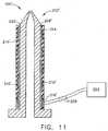
- the heater system 200comprises a layered heater 202 disposed around a body 203 of the hot runner nozzle 150', and a two-wire controller 204 in communication with the layered heater 202 through a single set of leads 205.
- the layered heater 202further comprises a substrate 206, which is configured to fit around the geometry of the hot runner nozzle 150' (shown as cylindrical).
- the layered heater 202further comprises a dielectric layer 208 disposed on the substrate 206, a resistive layer 210 disposed on the dielectric layer 208, and a protective layer 214 disposed on the resistive layer 210.
- terminal pads 216are disposed on the dielectric layer 208 and are in contact with the resistive layer 210. Accordingly, the electrical leads 205 are in contact with the terminal pads 216 and connect the resistive layer 210 to the two-wire controller 204. As a result, only one set of electrical leads 205 are required for the heater system 200, rather than one set for the layered heater 202 and another set for a separate temperature sensor.
- a layered heater 202'is disposed on an outer surface 220 of the hot runner nozzle 150' rather than on a separate substrate as previously described.
- the layered heater 202'comprises a dielectric layer 208' disposed on the outer surface 220, a resistive layer 210' disposed on the dielectric layer 208', and a protective layer 214' disposed on the resistive layer 210'.
- Terminal pads 216'are similarly disposed on the dielectric layer 208' and are in contact with the resistive layer 210'.
- the single set of leads 205'connect the heater 202' to the two-wire controller 204'.
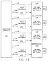
- a modular solution to retrofitting the heater system according to the present invention with existing controllers that use separate temperature sensors, e.g., thermocouples, RTDs, thermistors,is provided and illustrated in Figure 12 .
- two-wire modules 230are provided between layered heaters 232 and an existing temperature controller 234.
- the temperature controller 234comprises temperature sensor inputs 236 and power outputs 238.
- the two-wire modules 230thus contain the two-wire resistance measuring circuit as previously described, and the temperatures calculated within the two-wire modules 230 are transmitted to the temperature sensor inputs 236 of the existing temperature controller 234. Based on these temperature inputs, the temperature controller 234 controls the layered heaters 232 through the power outputs 238.
- power controlmay be a part of the temperature controller 234 or may be a separate power controller 240 as shown while remaining within the scope of the present invention. Accordingly, existing temperature controllers can be retrofitted with the two-wire modules 230 to implement the heater system of the present invention without substantial rework and modification of existing systems.
- the heater system 300comprises a layered heater 302 and a controller 304 that operate as previously described wherein a resistive layer (not shown) of the layered heater 302 is both a heating element and a temperature sensor.
- the heater system 300further comprises a power source 306, which is preferably low voltage in one form of the present invention, that provides power to the layered heater 302.
- the layered heater 302is connected to the controller 304 as shown through a single electrical lead 308 and through the body or structure of a device 310 (e.g., hot runner nozzle system mold) designated as a common return or neutral, wherein the common return device 310 provides an electrical return to the controller 304 from the layered heater 302.
- the heater system 300uses the electrically conductive nature of the device 310 materials to complete the electrical circuit, and thus a power source 306 is required to limit the current level travelling through the device 310. Therefore, since the device structure 310 is being used to connect the layered heater 302 to the controller 304, another electrical lead is eliminated such that the controller 304 is effectively a "single-wire controller.”
Landscapes
- Engineering & Computer Science (AREA)
- Manufacturing & Machinery (AREA)
- Mechanical Engineering (AREA)
- Control Of Resistance Heating (AREA)
- Moulds For Moulding Plastics Or The Like (AREA)
- Resistance Heating (AREA)
- Investigating Or Analyzing Materials By The Use Of Fluid Adsorption Or Reactions (AREA)
- Injection Moulding Of Plastics Or The Like (AREA)
- Control Of Temperature (AREA)
- Heat Treatment Of Strip Materials And Filament Materials (AREA)
Abstract
Description
- The present invention relates generally to electrical heaters and controllers and more particularly to temperature sensing for layered heaters.
- Layered heaters are typically used in applications where space is limited, when heat output needs vary across a surface, or in ultra-clean or aggressive chemical applications. A layered heater generally comprises layers of different materials, namely, a dielectric and a resistive material, which are applied to a substrate. The dielectric material is applied first to the substrate and provides electrical isolation between the substrate and the resistive material and also minimizes current leakage during operation. The resistive material is applied to the dielectric material in a predetermined pattern and provides a resistive heater circuit. The layered heater also includes leads that connect the resistive heater circuit to a heater controller and an over-mold material that protects the lead-to-resistive circuit interface. Accordingly, layered heaters are highly customizable for a variety of heating applications.
- Layered heaters may be "thick" film, "thin" film, or "thermally sprayed," among others, wherein the primary difference between these types of layered heaters is the method in which the layers are formed. For example, the layers for thick film heaters are typically formed using processes such as screen printing, decal application, or film printing heads, among others. The layers for thin film heaters are typically formed using deposition processes such as ion plating, sputtering, chemical vapor deposition (CVD), and physical vapor deposition (PVD), among others. Yet another process distinct from thin and thick film techniques is thermal spraying, which may include by way of example flame spraying, plasma spraying, wire arc spraying, and HVOF (High Velocity Oxygen Fuel), among others.
- Known systems that employ layered heaters typically include a separate temperature sensor, which is connected to the controller through another set of electrical leads in addition to the set of leads for the resistive heater circuit. The temperature sensor is often a thermocouple that is placed somewhere near the film heater and/or the process in order to provide the controller with temperature feedback for heater control. However, the thermocouple is relatively bulky, requires additional electrical leads, and fails relatively frequently. Alternately, an RTD (resistance temperature detector) may be incorporated within the layered heater as a separate layer in order to obtain more accurate temperature readings and to reduce the amount of space required as compared with a conventional thermocouple. Unfortunately, the RTD also communicates with the controller through an additional set of electrical leads. For systems that employ a large number of temperature sensors, the number of associated electrical leads for each sensor is substantial and results in added bulk and complexity to the overall heater system.
- For example, one such application where electrical leads add bulk and complexity to a heater system is with injection molding systems. Injection molding systems, and more specifically, hot runner systems, often include a large number of nozzles for higher cavitation molding, where multiple parts are molded in a single cycle, or shot. The nozzles are often heated to improve resin flow, and thus for each nozzle in the system, an associated set of electrical leads for a nozzle heater and a set of electrical leads for at least one temperature sensor (e.g., thermocouple) placed near the heater and/or the process must be routed from a control system to each nozzle. The routing of electrical leads is typically accomplished using an umbilical that runs from the control system to a hot runner mold system. Further, wiring channels are typically milled into plates of the mold system to route the leads to each nozzle, and therefore, an increased number of electrical leads adds cost and complexity to the hot runner mold system and adds bulk to the overall injection molding system.
- E.g.
DE 89 01 603 U1 relates to an electrical heater with a resistive layer.WO 97/21326 - The problem is solved by the invention with a heater system, a hot runner nozzle, and a method for operating a heater system according to the independent claims. Advantageous further developments are claimed in the dependent claims.
- A layered heater is provided that comprises at least one resistive layer, wherein the resistive layer has sufficient temperature coefficient of resistance characteristics such that the resistive layer is a heater element and a temperature sensor. The layered heater further comprises a two-wire controller connected to the resistive layer, wherein the two-wire controller determines temperature of the layered heater using the resistance of the resistive layer and controls heater temperature accordingly. In the various forms of the invention, the layered heater is a thick film heater, a thin film heater, a thermally sprayed heater, and a sol-gel heater.
- In yet another form, a hot runner nozzle heater system is provided that comprises at least one runner nozzle and at least one resistive layer disposed proximate the runner nozzle, wherein the resistive layer has sufficient temperature coefficient of resistance characteristics such that the resistive layer is a heater element and a temperature sensor. The heater system further comprises a two-wire controller connected to the resistive layer, wherein the two-wire controller determines temperature of the heater system using the resistance of the resistive layer and controls heater system temperature accordingly.
- According to a method of the present invention, operation of a layered heater is provided that comprises the steps of supplying power to the heater through a set of leads to a resistive element of the layered heater and calculating the temperature of the resistive element using a two-wire controller in communication with the layered heater through the set of leads, wherein the resistive element is a heater element and a temperature sensor. In another form, the method is used to operate a layered heater in conjunction with a hot runner nozzle.
- Further areas of applicability of the present invention will become apparent from the detailed description provided hereinafter.
- The present invention will become more fully understood from the detailed description and the accompanying drawings, wherein:
FIG. 1 is a block diagram of a heater system in accordance with the principles of the present invention;FIG. 2 is an enlarged cross-sectional view of a layered heater in accordance with the principles of the present invention;FIG. 3a is an enlarged cross-sectional view of a layered heater comprising a resistive layer and a protective layer in accordance with the principles of the present invention;FIG. 3b is an enlarged cross-sectional view of a layered heater comprising only a resistive layer in accordance with the principles of the present invention;FIG. 4a is a plan view of a resistive layer pattern constructed in accordance with the teachings of the present invention;FIG. 4b is a plan view of a second resistive layer pattern constructed in accordance with the principles of the present invention;FIG. 4c is a perspective view of a third resistive layer pattern constructed in accordance with the principles of the present invention;FIG. 5 is a block diagram illustrating a two-wire control system in accordance with the principles of the present invention;Figure 6 is a simplifed electrical schematic of a two-wire control system constructed in accordance with the teachings of the present invention;Figure 7 is a detailed electrical schematic of a two-wire control system constructed in accordance with the teachings of the present invention;Figure 8 is a perspective view of a high cavitation mold for an injection molding system having a heater system with hot runner nozzles and constructed in accordance with the teachings of the present invention;Figure 9 is a side view of a hot runner nozzle heater system constructed in accordance with the teachings of the present invention;Figure 10 is a side cross-sectional view of the hot runner nozzle heater system, taken along line A-A ofFigure 9 , in accordance with the principles of the present invention;Figure 11 is a side cross-sectional view of an alternate embodiment of the hot runner nozzle heater system constructed in accordance with the teachings of the present invention;Figure 12 is a schematic diagram of a modular heater system for retrofit into existing systems in accordance with the principles of the present invention; andFigure 13 is a block diagram of a heater system using a single wire in accordance with the principles of the present invention.- Corresponding reference numerals indicate corresponding parts throughout the several views of the drawings.
- The following description of the preferred embodiments is merely exemplary in nature and is in no way intended to limit the invention, its application, or uses.
- Referring to
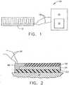
Figure 1 , a simplified heater system in block diagram format in accordance with one form of the present invention is illustrated and generally indicated byreference numeral 10. Theheater system 10 comprises alayered heater 12, a two-wire controller 14, which is preferably microprocessor based, and apower source 16 within or connected to the two-wire controller 14. The layeredheater 12 is connected to the two-wire controller 14 as shown through a single set of electrical leads 18. Power is provided to the layeredheater 12 through the electrical leads 18, and temperature information of the layeredheater 12 is provided on command to the two-wire controller 14 through the same set of electrical leads 18. More specifically, the two-wire controller 14 determines the temperature of the layeredheater 12 based on a calculated resistance, one technique of which is described in greater detail below. The two-wire controller 14 then sends signals to thepower source 16 to control the temperature of the layeredheater 12 accordingly. Therefore, only a single set ofelectrical leads 18 is required rather than one set for the heater and one set for a temperature sensor. - Referring now to
Figure 2 , in one form the layeredheater 12 comprises a number of layers disposed on asubstrate 20, wherein thesubstrate 20 may be a separate element disposed proximate the part or device to be heated, or the part or device itself. As shown, the layers preferably comprise adielectric layer 22, aresistive layer 24, and aprotective layer 26. Thedielectric layer 22 provides electrical isolation between thesubstrate 20 and theresistive layer 24 and is disposed on thesubstrate 20 in a thickness commensurate with the power output of the layeredheater 12. Theresistive layer 24 is disposed on thedielectric layer 22 and provides two primary functions in accordance with the present invention. First, theresistive layer 24 is a resistive heater circuit for the layeredheater 12, thereby providing the heat to thesubstrate 20. Second, theresistive layer 24 is also a temperature sensor, wherein the resistance of theresistive layer 24 is used to determine the temperature of the layeredheater 12 as described in greater detail below. Theprotective layer 26 is preferably an insulator, however other materials such as a conductive material may also be employed according to the requirements of a specific heating application while remaining within the scope of the present invention. - As further shown,
terminal pads 28 are disposed on thedielectric layer 22 and are in contact with theresistive layer 24. Accordingly, electrical leads 30 are in contact with theterminal pads 28 and connect theresistive layer 24 to the two-wire controller 14 (not shown) for power input and for transmission of heater temperature information to the two-wire controller 14. Further, theprotective layer 26 is disposed over theresistive layer 24 and is preferably a dielectric material for electrical isolation and protection of theresistive layer 24 from the operating environment. Since theresistive layer 24 functions as both a heating element and a temperature sensor, only one set ofelectrical leads 30, (e.g., two wires), are required for theheater system 10, rather than one set for the layeredheater 12 and another set for a separate temperature sensor. Thus, the number of electrical leads for any given heater system is reduced by 50% through the use of theheater system 10 according to the present invention. Additionally, since the entireresistive layer 24 is a temperature sensor in addition to a heater element, temperature is sensed throughout the entire heater element rather than at a single point as with many conventional temperature sensors such as a thermocouple. - In another form of the present invention as shown in
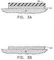
Figure 3a , theresistive layer 24 is disposed on thesubstrate 20 in the case where thesubstrate 20 is not conductive and electrical isolation is not required through a separate dielectric layer. As shown, theprotective layer 26 is disposed over theresistive layer 24 as previously described. In yet another form as shown inFigure 3b , theresistive layer 24 is disposed on thesubstrate 20 with nodielectric layer 22 and noprotective layer 26. Accordingly, theheater system 10 of the present invention is operable with at least one layer, namely, theresistive layer 24, wherein theresistive layer 24 is both a heating element and a temperature sensor. Other combinations of functional layers not illustrated herein may also be employed according to specific application requirements while remaining within the scope of the present invention. - Generally, the layered
heater 12 is configured for operation with any number of devices that require heating, one of which is hot runner nozzles for injection molding systems as described in greater detail below. Furthermore, the layeredheater 12 is preferably a thick film heater that is fabricated using a film printing head in one form of the present invention. Fabrication of the layers using this thick film process is shown and described-inU.S. Patent No. 5,973,296 , which is commonly assigned with the present application and the contents of which are incorporated herein by reference in their entirety. Additional thick film processes may include, by way of example, screen printing, spraying, rolling, and transfer printing, among others. - However, in another form, the layered
heater 12 is a thin film heater, wherein the layers are formed using thin film processes such, as ion plating, sputtering, chemical vapor deposition (CVD), and physical vapor deposition (PVD), among others. Thin film processes such as those disclosed inU.S. Patent Nos. 6,305,923 ,6,341,954 , and6,575,729 , which are incorporated herein by reference in their entirety, may be employed with theheater system 10 as described herein while remaining within the scope of the present invention. In yet another form, the layeredheater 12 is a thermal sprayed heater, wherein the layers are formed using thermal spraying processes such as flame spraying, plasma spraying, wire arc spraying, and HVOF (High Velocity Oxygen Fuel), among others. In still another form, the layeredheater 12 is a "sol-gel" heater, wherein the layers are formed using sol-gel materials. Generally, the sol-gel layers are formed using processes such as dipping, spinning, or painting, among others. Thus, as used herein, the term "layered heater" should be construed to include heaters that comprise at least one functional layer (e.g.,resistive layer 24 only,resistive layer 24 andprotective layer 26,dielectric layer 22 andresistive layer 24 andprotective layer 26, among others), wherein the layer is formed through application or accumulation of a material to a substrate or another layer using processes associated with thick film, thin film, thermal spraying, or sol-gel, among others. These processes are also referred to as "layered processes" or "layered heater processes." - In order for the
resistive layer 24 to serve both the function of a temperature sensor in addition to a heater element, theresistive layer 24 is preferably a material having a relatively high temperature coefficient of resistance (TCR). As the resistance of metals increases with temperature, the resistance at any temperaturet (°C) is:
where: R0 is the resistance at some reference temperature (often 0°C) and α is the temperature coefficient of resistance (TCR). Thus, to determine the temperature of the heater, a resistance of the heater is calculated by the two-wire controller 14 as described in greater detail below. In one form, the voltage across and the current through the heater is measured using the two-wire controller 14, and a resistance is calculated based on Ohm's law. UsingEquation 1, or similar equations known to those skilled in the art of temperature measurement using Resistance Temperature Detectors (RTDs), and the known TCR, temperature of theresistive layer 24 is then calculated and used for heater control. - Therefore, in one form of the present invention, a relatively high TCR is preferred such that a small temperature change results in a large resistance change. Therefore, formulations that include materials such as platinum (TCR = 0.0039 Ω/Ω/°C), nickel (TCR = 0.0041 Ω/Ω/°C), or copper (TCR = 0.0039 Ω/Ω/°C), and alloys thereof, are preferred for the
resistive layer 24. - However, in other forms of the present invention, a material for the
resistive layer 24 need not necessarily have a high TCR. For example, a negative TCR material, or a material having a non-linear TCR, would also fall within the scope of the present invention, as long as the TCR is predictable. If the TCR of a given material is known, if it can be measured with the necessary accuracy, and if it is repeatable or predictable, then the material could be used to determine temperature of theheater system 10. Such a TCR, including the relatively high TCR materials as described, are hereinafter referred to as having sufficient TCR characteristics. Accordingly, the materials described herein and their related high TCRs should not be construed as limiting the scope of the present invention. The relatively high TCR as described herein are preferred in one form of the present invention. - As another sufficient TCR characteristic, the material used for the
resistive layer 24 must not exhibit excessive "drift," which is a tendency of many resistive elements to change characteristics, such as bulk resistivity or TCR, over time. Therefore, the material for theresistive layer 24 is preferably stable or predictable in terms of drift, however, the drift can be compensated for over time through calibration of the two-wire controller 14 that is described in greater detail below. Additionally, drift can be reduced or eliminated through "burn-in" of the heater to induce any resistance shift that would occur over time. Accordingly, theresistive layer 24 is preferably a material that has a relatively high temperature coefficient of resistance and that is stable in terms of drift. However, if the drift is predictable, the material may be used for the resistive layer while remaining within the scope of the present invention. - In one form of the present invention, the
resistive layer 24 is formed by printing a resistive material on thedielectric layer 22 as previously set forth. -More specifically, two (2) resistive materials were.tested for use in the present invention, RI1 and RI2, wherein the TCR of RI1 was between approximately 0.0008 Ω/Ω/°C and approximately 0.0016 Ω/Ω/°C, and the TCR of RI2 was between approximately 0.0026/ /°C and approximately 0.0040//°C. Additionally, temperature drift was tested for RI1 and RI2, at various temperatures, and the drift varied from approximately 3% for RI1 to approximately 10% for RI2. With a "burn-in" as previously described, the drift was shown to have been reduced to approximately 2% for RI1 to approximately 4% for RI2. The materials for the
resistive layer 24 and their respective values for TCR and temperature drift as described herein are exemplary in nature and should not be construed as limiting the scope of the present invention. Any resistive material having sufficient TCR characteristics as previously set forth can be utilized for theresistive layer 24 while remaining within the scope of the present invention. - Since a plurality of layered heaters having temperature sensing capabilities are employed according to the present invention, the two-
wire controller 14 must be provided with TCR characteristics (TCR at a temperature and/or over a temperature range) about the heaters, and more specifically theresistive layers 24, in order to properly calibrate the overall heater system. Parameters that are necessary for such calibration further include the cold resistance, the temperature at which the cold resistance value was measured, in order to determine heater temperature from heater resistance calculations. Preferably, the system automatically calculates the cold resistance of eachlayered heater 12 based on the measured voltage and current using the two-wire controller 14 as described in greater detail below. Additionally, the TCR characteristics for eachlayered heater 12 must be entered into the system, e.g. the two-wire controller 14, using manual and/or electronic methods. - Such values may be entered individually or as a single value for all layered
heaters 12 depending on, for example, whether or not the material for theresistive layer 24 came from a common manufacturing lot. Regardless, the calibration data, namely, the cold resistance, cold resistance temperature, and TCR of eachlayered heater 12 is preferably entered into the two-wire controller 14 for more accurate and controlled operation of theheater system 10. - A variety of methods of providing the TCR characteristics and cold resistance data of each
layered heater 12 to the two-wire controller 14 may be employed while remaining within the scope of the present invention. For example, eachlayered heater 12 may include a bar-coded tag that would be scanned by an operator to download the cold resistance data and TCR characteristics to the two-wire controller 14. Alternately, a smart card chip or other electronic means may be attached to eachlayered heater 12, which would similarly be scanned by an operator to download the calibration data to the two-wire controller 14. In yet another form, the calibration data may be downloaded to the two-wire controller 14 via the Internet, for example, through a supplier website. Alternately, the TCR characteristics and cold resistance data may be pre-programmed into the two-wire controller 14. - In addition to calibration for resistance data and TCR, compensation for the resistance of
electrical leads 30 is also provided by theheater system 10 according to the present invention. Since the electrical leads 30 add resistance to the circuit, temperature errors would likely result if no compensation for the increase in resistance were provided. Additionally, the materials used for the electrical leads 30 may have a TCR higher than that of theresistive layer 24, which results in the portion of the electrical leads 30 that are exposed to higher temperatures contributing more resistance. Therefore, the two-wire controller 14 also provides for calibration of lead wire resistance. - The two-
wire controller 14 is preferably designed with temperature calibration capabilities, which further reduces long term temperature errors due to drift. One method of temperature calibration is accomplished by using one or more pre-existing thermocouples, or other pre-existing temperature sensors, to ascertain both the temperature and the stability of the temperature. The temperature data from the thermocouples is then transmitted to the two-wire controller 14 for the resistance calculations. Further, changes in the measured cold resistance of the layeredheater 12 may be used to calculate new TCR values as appropriate. In another form for temperature calibration, the two-wire controller 14 preferably comprises a calibration offset feature that provides for input of a temperature offset parameter. Such an offset is desirable when the location of the layeredheater 12 is some distance away from the optimum location for sensing temperature. Thus, the temperature offset parameter may be used such that theheater system 10 provides a temperature that more closely represents the actual temperature at the optimum location. - Turning now to the construction of the layered
heater 12 as shown inFigures 4a-4c , theresistive layer 24 is preferably disposed on thedielectric layer 22 in a pattern 40 that results in a desired temperature profile for the given substrate or element being heated.Figure 4a shows aresistive layer 24a in arectangular pattern 40a based on the rectangular profile of thesubstrate 20a.Figure 4b shows aresistive layer 24b in acircular pattern 40b based on the circular profile of thesubstrate 20b.Figure 4c shows aresistive layer 24c in aspiral pattern 40c based on a cylindrical.shape of thesubstrate 20c. Additionally, the width "W" and/or pitch "P" of thepatterns 40a-c may also be altered according to the specific heating requirements of the heater system. Therefore, the pattern of theresistive layer 24a is preferably customized for each application of theheater system 10. The patterns illustrated herein are exemplary only and are not intended to limit the scope of the present invention. - The layered
heater 12, including each of the layers and theterminal pads 28 may also be constructed in accordance withU.S. Pat. Nos. 6,410,894 ,6,222,166 ,6,037,574 ,5,973,296 , and5,714,738 . Accordingly, additional specificity with regard to further materials, manufacturing techniques, and construction approaches are not included herein for purposes of clarity and reference is thus made to the patents incorporated by reference herein for such additional information. - One form of the two-
wire controller 14 is illustrated in block diagram format inFIG. 5 . As shown, the two-wire controller 14 generally comprises apower source 50, a voltage andcurrent measurement component 52, apower regulator component 54, and amicroprocessor 56 in communication with the layeredheater 12. Themicroprocessor 56 is also in communication with acommunications component 58, where temperature readings from theheater system 10 is delivered and also where TCR characteristics and e.g. calibration data, temperature set points, resistance set points may be provided to theheater system 10. - Referring now to
FIG. 6 , thevoltage measurement component 52 of the two-wire controller 14 is illustrated in greater detail. Generally, the two-wire controller 14 applies a DC bias, or low level DC current, to the layeredheater 12 during an AC power cycle zero-cross interval so that the current value times a nominal heater resistance results in a voltage that is higher than the full wave voltage at the zero crossing for a time period on each side of the zero value. During the time interval, the voltage of the layeredheater 12 is amplified and compared to a reference voltage, and power to the layeredheater 12 is then controlled as further described herein. Application of the DC bias is further shown and described inU.S. Pat. No. 4,736,091 . In another form of the present invention, an AC current may be used for the bias instead of the DC bias to determine the resistance of the layeredheater 12. - As shown, the two-
wire controller 14 comprises atransistor 60, adiode 62, and afirst resistor 64, wherein thefirst resistor 64 together with the layeredheater 12 form a voltage divider. For the DC bias, thetransistor 60 is turned on for a short time period, e.g., 200 µs, during the zero cross interval and further prevents current flow through the power source 50 (not shown) during negative half cycles when the heater is receiving power. Additionally, thediode 62 prevents current flow through thepower source 50 during positive half cycles when the layeredheater 12 is receiving power. The output of the layeredheater 12 is then sent through asecond resistor 66 and into anopamp circuit 68 that comprises anamplifier 70 andresistors amplifier 70 is thus used to calculate resistance and determine the temperature of the layeredheater 12, wherein the output voltage of theamplifier 70 is read by an A/D converter within themicroprocessor 56. Further, during the DC bias time period, conversion of the output voltage of theamplifier 70 from an analog signal to a digital signal takes place, and a gating pulse from atriac 80 is delivered to the layeredheater 12 if the calculated resistance, or layeredheater 12 temperature, is such that a control algorithm has determined a need for additional power from the layeredheater 12. As further shown, afield effect transistor 82 clamps the input of theamplifier 70, thereby preventing theamplifier 70 from being over driven during both positive and negative half cycles when the heater is receiving line power. - The
microprocessor 56, which is described in greater detail below, generally communicates with the circuit shown through anoutput control 84, abias control 86, andheater input 88. Additionally, themicroprocessor 56 further comprisesfirmware 90, and/or software (not shown). Thefirmware 90 may be programmed for a variety of functions, including but not limited to, allowing half cycle delivery of power to improve controllability or full cycle power in accordance with IEEE 519. As a further example, thefirmware 90 may include control algorithms to compensate for thermal transient response and other calibration data as previously described. Therefore, themicroprocessor 56 is used in combination with the DC bias circuitry to determinelayered heater 12 temperature and to more efficiently control power to the layeredheater 12. - A further expansion of the two-
wire controller 14 is now shown in greater detail inFigure 7 . Thepower source 50 is preferably non-isolated and capacitively coupled with alinear regulator 100 as shown. Thepower source 50 thus regulates an alternating current down to a specified value as required for operation. As further shown, the sine wave for the zero-cross (DC biasing) from thepower source 50 is in communication with themicroprocessor 56. During the zero-cross interval, the DC bias is applied through thetransistor 102, diode 104, andresistor 106. The voltage across the layeredheater 12 is amplified and offset by theamplifier 108, and theamplifier 110 is used as a reference for the A/D converter within themicroprocessor 56 for temperature variances. - Measurement of the change in voltage across and current through the layered
heater 12 is accomplished using thedual amplifiers analog switches amplifier 112 andanalog switch 116, and the change in current is throughamplifier 114 andanalog switch 118. As further shown, the change in current is measured using ashunt resistor 116. Additionally, the two-wire controller 14 comprises atriac 120 that is out of conduction at the zero-cross and is conducting on each half cycle. During the DC biasing interval, an A/D conversion takes place and thetriac 120 delivers a pulse if the measured resistance is such that the control algorithm has determined a need for additional power from the layeredheater 12. Therefore, two methods of calculating resistance are provided by the circuit shown inFigure 7 , namely, the DC bias circuit and the shunt resistor circuit. Additionally, although the present invention preferably measures voltage and current to determine resistance, alternate methods of determining resistance such as a voltage gate or using a known current may also be employed while remaining within the scope of the present invention. - In yet another form, the
triac 120 is preferably a random fire triac such that the layeredheater 12 is fired at high conduction angles to reduce the amount of energy that is delivered to the layeredheater 12 during sampling. For example, firing the layeredheater 12 at conduction angles of 160° and 340° allows for sufficient sampling at 120Hz with reduced energy input to the layeredheater 12. Alternately, sampling at only 160° or only 340° would result in a sampling rate of 60Hz while reducing the energy input further in half. Additionally, when using a random fire triac, any rate function may be applied by delivering energy in smaller increments as the temperature (or resistance in another form) approaches the set point. Accordingly, the layeredheater 12 is fired at higher and higher conduction angles into a full line cycle. - As further shown, communications to and from the two-
wire controller 14 take place on the opposite side of themicroprocessor 56. Thecommunications component 58 comprises a series of opto-isolators line transceiver 128. Therefore, communications can be made through any number of protocols, including by way of example, RS-485 communications as illustrated herein. In addition to other functions, calibration data can be entered utilizing this communications interface. - The
firmware 90 is loaded into themicroprocessor 56 using the ISP (In-System Programming) connections as shown. Therefore, certain modifications to the settings within the two-wire controller 14, including entry of calibration data as previously described, can be accomplished in an efficient manner. - The specific circuit components, along with the values and configuration of the circuit components, (e.g., resistor values, capacitor values, among others), as detailed in
Figure 7 are exemplary of one form of the two-wire controller 14 and should not be construed as limiting the scope of the present invention. Accordingly, alternate circuit components, configurations, and values, and resistance measuring circuit topologies may be implemented in a two-wire configuration as defined herein while remaining within the scope of the present invention. - One known application for the
heater system 10 according to the principles of the present invention is for hot runner nozzles in injection molding systems as shown inFigure 8 . Thehot runner nozzles 150 are typically disposed within a hotrunner mold system 152, which further comprises a plurality ofmold wiring channels 154 that provide for routing of electrical leads (not shown) that run from heaters (not shown) disposed proximate thehot runner nozzles 150 to a two-wire controller (not shown) as described herein. Since each heater serves as both a heating element and as a temperature sensor, only one set of leads per heater is required rather than one set of leads for the heater and one set of leads for a temperature sensor. As a result, the amount of leads running through themold wiring channels 154 is reduced in half and the related bulk and complexity is drastically reduced. - Additionally, injection molding equipment typically includes an umbilical 164 that runs from the controller to the hot
runner mold system 152, wherein all of the leads and other related electrical components are disposed. With the drastic reduction in the number of leads provided by the present invention, the size and bulk of the umbilical 164 is also drastically reduced. Moreover, since the temperature is being sensed by the entire resistive layer of the heater, the temperature is being sensed over a length rather than at a point with a conventional thermocouple. - Referring now to
Figures 9 and10 , the heater system for a hot runner nozzle 150' is illustrated in greater detail. Theheater system 200 comprises alayered heater 202 disposed around abody 203 of the hot runner nozzle 150', and a two-wire controller 204 in communication with thelayered heater 202 through a single set of leads 205. Thelayered heater 202 further comprises asubstrate 206, which is configured to fit around the geometry of the hot runner nozzle 150' (shown as cylindrical). Thelayered heater 202 further comprises adielectric layer 208 disposed on thesubstrate 206, aresistive layer 210 disposed on thedielectric layer 208, and aprotective layer 214 disposed on theresistive layer 210. As further shown,terminal pads 216 are disposed on thedielectric layer 208 and are in contact with theresistive layer 210. Accordingly, theelectrical leads 205 are in contact with theterminal pads 216 and connect theresistive layer 210 to the two-wire controller 204. As a result, only one set ofelectrical leads 205 are required for theheater system 200, rather than one set for thelayered heater 202 and another set for a separate temperature sensor. - As shown in
Figure 11 , in an alternate form a layered heater 202' is disposed on anouter surface 220 of the hot runner nozzle 150' rather than on a separate substrate as previously described. Similarly, the layered heater 202' comprises a dielectric layer 208' disposed on theouter surface 220, a resistive layer 210' disposed on the dielectric layer 208', and a protective layer 214' disposed on the resistive layer 210'. Terminal pads 216' are similarly disposed on the dielectric layer 208' and are in contact with the resistive layer 210'. As further shown, the single set of leads 205' connect the heater 202' to the two-wire controller 204'. - In yet another form of the present invention, a modular solution to retrofitting the heater system according to the present invention with existing controllers that use separate temperature sensors, e.g., thermocouples, RTDs, thermistors, is provided and illustrated in
Figure 12 . As shown, two-wire modules 230 are provided betweenlayered heaters 232 and an existingtemperature controller 234. Thetemperature controller 234 comprisestemperature sensor inputs 236 and power outputs 238. The two-wire modules 230 thus contain the two-wire resistance measuring circuit as previously described, and the temperatures calculated within the two-wire modules 230 are transmitted to thetemperature sensor inputs 236 of the existingtemperature controller 234. Based on these temperature inputs, thetemperature controller 234 controls the layeredheaters 232 through the power outputs 238. It should be understood that power control may be a part of thetemperature controller 234 or may be aseparate power controller 240 as shown while remaining within the scope of the present invention. Accordingly, existing temperature controllers can be retrofitted with the two-wire modules 230 to implement the heater system of the present invention without substantial rework and modification of existing systems. - Referring now to
Figure 13 , another form of a heater system according the present invention that reduces the number of electrical leads is illustrated and generally indicated byreference numeral 300. Theheater system 300 comprises alayered heater 302 and acontroller 304 that operate as previously described wherein a resistive layer (not shown) of thelayered heater 302 is both a heating element and a temperature sensor. Theheater system 300 further comprises apower source 306, which is preferably low voltage in one form of the present invention, that provides power to thelayered heater 302. Thelayered heater 302 is connected to thecontroller 304 as shown through a singleelectrical lead 308 and through the body or structure of a device 310 (e.g., hot runner nozzle system mold) designated as a common return or neutral, wherein thecommon return device 310 provides an electrical return to thecontroller 304 from the layeredheater 302. Theheater system 300 uses the electrically conductive nature of thedevice 310 materials to complete the electrical circuit, and thus apower source 306 is required to limit the current level travelling through thedevice 310. Therefore, since thedevice structure 310 is being used to connect thelayered heater 302 to thecontroller 304, another electrical lead is eliminated such that thecontroller 304 is effectively a "single-wire controller."


Claims (11)
- A heater system (10; 200; 300) comprising: a layered heater (12; 202; 302) comprising at least one resistive layer (24; 210), wherein the layered heater (12; 202; 302) is selected from a group consisting of thick film, thin film, thermal spray, and sol-gel, and the resistive layer (24; 210) having sufficient temperature coefficient of resistance characteristics such that the resistive layer (24;210) is a heater element and a temperature sensor; two electrical lead wires (30) connected to the resistive layer (24; 210); and a two-wire controller (14; 204) connected to the resistive layer (24; 210) through the two electrical lead wires (30), wherein the two-wire controller (14; 204) determines temperature of the layered heater (12; 202; 302) using the resistance of the resistive layer (24; 210) and controls heater temperature accordingly through the two electrical lead wires (30), wherein the heater system (10; 200; 300) provides heat to a part to be heated;characterized in that the two-wire controller (14; 204) further comprises a microprocessor (56) and a communications component (58), the microprocessor being in communication with the communications component (58), where temperature readings from the heater system (10) is delivered and also where TCR characteristics are provided to the heater system (10).
- The heater system (10; 200; 300) according to claim 1, wherein the two-wire controller (14; 204) comprises a DC bias control, an AC bias control, or a shunt resistor for calculation of the resistance of the resistive layer (24; 210).
- The heater system (10; 200; 300) according to any of the preceding claims, wherein the two-wire controller (14; 204) comprises high conduction angle firing.
- The heater system (10; 200; 300) according to any of the preceding claims, wherein the resistive layer (24; 210) defines a pattern selected from the group consisting of spiral, rectangular, and circular.
- The heater system (10; 200; 300) according to any of the preceding claims, wherein the two-wire controller (14; 204) further comprises firmware.
- The heater system (10; 200; 300) according to any of the preceding claims, further comprising a substrate (20; 206) disposed proximate the part to be heated, and at least one dielectric layer (22; 208) disposed on the substrate 20; 206), the at least one resistive layer (24; 210) being disposed on the dielectric layer (22; 208).
- The heater system (10; 200; 300) according to any of the preceding claims, further comprising a protective layer (26, 214) that is disposed over the resistive layer (24; 210).
- A hot runner nozzle (150),characterized in that it comprises a heater system (10; 200; 300) according to any of the preceding claims, the part to be heated being the hot runner nozzle (150) and the resistive layer (24; 210) being disposed around the hot runner nozzle (150).
- The hot runner nozzle (150) according to claim 8, wherein the resistive layer (24; 210) is disposed proximate the hot runner nozzle (150).
- A method of operating a heater system (10; 200; 300) according to one of claims 1-7, comprising the steps of: supplying power to the layered heater (12; 202; 302) through a set of electrical leads (18; 205) to a resistive layer (24; 210) of the layered heater (12; 202; 302); and calculating the temperature of the resistive layer (24; 210) using a two-wire controller (14; 204) connected to the layered heater (12; 202; 302) through the set of electrical leads (18; 205), wherein the resistive layer (24; 210) is a heater element and a temperature sensor.
- The method according to claim 10, further comprising the step of resistance data calibration and/or lead wire calibration and/or temperature calibration and/or TCR calibration.
Priority Applications (1)
| Application Number | Priority Date | Filing Date | Title |
|---|---|---|---|
| PL04812091TPL1692920T3 (en) | 2003-11-21 | 2004-11-19 | Two-wire layered heater system |
Applications Claiming Priority (2)
| Application Number | Priority Date | Filing Date | Title |
|---|---|---|---|
| US10/719,327US7196295B2 (en) | 2003-11-21 | 2003-11-21 | Two-wire layered heater system |
| PCT/US2004/039500WO2005053360A2 (en) | 2003-11-21 | 2004-11-19 | Two-wire layered heater system |
Publications (4)
| Publication Number | Publication Date |
|---|---|
| EP1692920A2 EP1692920A2 (en) | 2006-08-23 |
| EP1692920A4 EP1692920A4 (en) | 2008-01-16 |
| EP1692920B1 EP1692920B1 (en) | 2009-06-03 |
| EP1692920B2true EP1692920B2 (en) | 2017-11-22 |
Family
ID=34591294
Family Applications (1)
| Application Number | Title | Priority Date | Filing Date |
|---|---|---|---|
| EP04812091.9AExpired - LifetimeEP1692920B2 (en) | 2003-11-21 | 2004-11-19 | Two-wire layered heater system |
Country Status (12)
| Country | Link |
|---|---|
| US (5) | US7196295B2 (en) |
| EP (1) | EP1692920B2 (en) |
| CN (1) | CN100556217C (en) |
| AT (1) | ATE433275T1 (en) |
| CA (1) | CA2546826C (en) |
| DE (1) | DE602004021420D1 (en) |
| ES (1) | ES2327934T5 (en) |
| MX (1) | MXPA06005752A (en) |
| PL (1) | PL1692920T3 (en) |
| PT (1) | PT1692920E (en) |
| TW (1) | TWI290004B (en) |
| WO (1) | WO2005053360A2 (en) |
Families Citing this family (117)
| Publication number | Priority date | Publication date | Assignee | Title |
|---|---|---|---|---|
| US6731925B2 (en)* | 2001-10-24 | 2004-05-04 | Mouhamad Ahmad Naboulsi | Safety control system for vehicles |
| US7196295B2 (en)* | 2003-11-21 | 2007-03-27 | Watlow Electric Manufacturing Company | Two-wire layered heater system |
| US8536496B2 (en)* | 2004-09-15 | 2013-09-17 | Watlow Electric Manufacturing Company | Adaptable layered heater system |
| EP1803328B1 (en)* | 2004-09-30 | 2012-04-11 | Watlow Electric Manufacturing Company | Modular layered heater system |
| TWI252813B (en)* | 2004-11-10 | 2006-04-11 | Benq Corp | Fluid injector device with sensors and method of manufacturing the same |
| US7465165B2 (en)* | 2005-04-07 | 2008-12-16 | Mold-Masters (2007) Limited | Configurable manifold |
| US20060289469A1 (en)* | 2005-04-21 | 2006-12-28 | Noble Fiber Technologies Llc | Flexible electrically conductive circuits |
| WO2007009232A1 (en)* | 2005-07-18 | 2007-01-25 | Datec Coating Corporation | Low temperature fired, lead-free thick film heating element |
| KR100645688B1 (en)* | 2005-08-30 | 2006-11-14 | 삼성에스디아이 주식회사 | Heater of evaporation apparatus and evaporation source employing same |
| US7280750B2 (en)* | 2005-10-17 | 2007-10-09 | Watlow Electric Manufacturing Company | Hot runner nozzle heater and methods of manufacture thereof |
| US9498277B2 (en)* | 2007-02-01 | 2016-11-22 | Conmed Corporation | Apparatus and method for rapid reliable electrothermal tissue fusion and simultaneous cutting |
| US9492220B2 (en)* | 2007-02-01 | 2016-11-15 | Conmed Corporation | Apparatus and method for rapid reliable electrothermal tissue fusion |
| US20080188845A1 (en)* | 2007-02-01 | 2008-08-07 | Mcgreevy Francis T | Tissue fusion instrument and method to reduce the adhesion of tissue to its working surfaces |
| CA2632093A1 (en)* | 2007-05-25 | 2008-11-25 | Mold-Masters (2007) Limited | Hot runner having temperature sensor for controlling nozzle heater and related method |
| US7800021B2 (en)* | 2007-06-30 | 2010-09-21 | Husky Injection Molding Systems Ltd. | Spray deposited heater element |
| US8557082B2 (en) | 2007-07-18 | 2013-10-15 | Watlow Electric Manufacturing Company | Reduced cycle time manufacturing processes for thick film resistive devices |
| US8089337B2 (en)* | 2007-07-18 | 2012-01-03 | Watlow Electric Manufacturing Company | Thick film layered resistive device employing a dielectric tape |
| KR101288665B1 (en)* | 2007-08-24 | 2013-07-22 | 허스키 인젝션 몰딩 시스템즈 리미티드 | An apparatus for controlling melt flow in a melt distribution network |
| DE202007014964U1 (en)* | 2007-10-25 | 2009-02-26 | Günther Heisskanaltechnik Gmbh | connecting device |
| US10159114B2 (en)* | 2008-03-18 | 2018-12-18 | Watlow Electric Manufacturing Company | Layered heater system with honeycomb core structure |
| US8061402B2 (en)* | 2008-04-07 | 2011-11-22 | Watlow Electric Manufacturing Company | Method and apparatus for positioning layers within a layered heater system |
| US20100025391A1 (en)* | 2008-07-31 | 2010-02-04 | Itherm Technologies, L.P. | Composite inductive heating assembly and method of heating and manufacture |
| WO2010045221A1 (en)* | 2008-10-13 | 2010-04-22 | Egc Enterprises, Incorporated | Temperature monitoring and control system for negative temperature coefficient heaters |
| US9345067B2 (en)* | 2008-10-13 | 2016-05-17 | ECG Operating Company LLC | Temperature monitoring and control system for negative temperature coefficient heaters |
| IT1392225B1 (en)* | 2008-12-12 | 2012-02-22 | Microglass S R L | METHOD OF REGULATION AND AUTOMATIC CONTROL OF THE HEATING AND HEATING TEMPERATURE OF HEATING COMPONENTS INTENDED TO HEAT SURFACES OR ROOMS IN PARTICULAR FOR HEATING EQUIPMENT AND FOR VARIOUS TYPES OF APPLICATION. |
| IT1392224B1 (en)* | 2008-12-12 | 2012-02-22 | Microglass S R L | ELECTRONIC CONTROL DEVICE FOR THE AUTOMATIC ADJUSTMENT OF THE HEATING POWER AND TEMPERATURE OF HEATING COMPONENTS INTENDED TO HEAT SURFACES OR ROOMS, IN PARTICULAR FOR HEATING EQUIPMENT AND FOR VARIOUS TYPES OF APPLICATION. |
| CA2806274C (en) | 2010-07-22 | 2017-01-17 | Watlow Electric Manufacturing Company | Combination fluid sensor system |
| US8840609B2 (en) | 2010-07-23 | 2014-09-23 | Conmed Corporation | Tissue fusion system and method of performing a functional verification test |
| US8927909B2 (en)* | 2010-10-11 | 2015-01-06 | Stmicroelectronics, Inc. | Closed loop temperature controlled circuit to improve device stability |
| US9062354B2 (en)* | 2011-02-24 | 2015-06-23 | General Electric Company | Surface treatment system, a surface treatment process and a system treated component |
| US8692605B2 (en)* | 2011-06-27 | 2014-04-08 | Mediatek Inc. | Receiving circuits for core circuits |
| WO2013033350A1 (en)* | 2011-08-30 | 2013-03-07 | Watlow Electric Manufacturing Company | Thermal array system |
| CN103959900B (en) | 2011-09-29 | 2016-08-24 | 沃特洛电气制造公司 | High dynamic temperature control system |
| CN102361520B (en)* | 2011-10-21 | 2013-11-27 | 无锡绿波新能源设备有限公司 | Temperature control feedback electric heating plate |
| DE102012103120B4 (en)* | 2012-04-11 | 2025-04-30 | Günther Heisskanaltechnik Gmbh | Tool insert with layer heating, mold plate with such a tool insert and method for operating such a tool insert |
| JP5536136B2 (en)* | 2012-04-19 | 2014-07-02 | 株式会社九州日昌 | Thermostatic device |
| US9224626B2 (en) | 2012-07-03 | 2015-12-29 | Watlow Electric Manufacturing Company | Composite substrate for layered heaters |
| US20140034628A1 (en)* | 2012-08-06 | 2014-02-06 | Chien-Chou Chen | Temperature control module for electric blankets |
| EP3000282A1 (en)* | 2013-05-21 | 2016-03-30 | Heat Trace Limited | Electrical heater |
| US9987782B2 (en)* | 2013-09-10 | 2018-06-05 | Otto Männer Innovation GmbH | Hot runner nozzle with a segmented heater |
| US9716022B2 (en) | 2013-12-17 | 2017-07-25 | Lam Research Corporation | Method of determining thermal stability of a substrate support assembly |
| DK2908036T3 (en)* | 2014-02-18 | 2016-05-30 | Möhlenhoff GmbH | Switching arrangement for setting a valve |
| JP6219227B2 (en) | 2014-05-12 | 2017-10-25 | 東京エレクトロン株式会社 | Heater feeding mechanism and stage temperature control method |
| US10440829B2 (en)* | 2014-07-03 | 2019-10-08 | United Technologies Corporation | Heating circuit assembly and method of manufacture |
| DE102014113482B4 (en)* | 2014-09-18 | 2019-01-03 | Bruker Daltonik Gmbh | Ionization chamber with tempered gas supply |
| WO2016069808A1 (en) | 2014-10-31 | 2016-05-06 | Watlow Electric Manufacturing Company | Thermal dynamic response sensing systems for heaters |
| GB2533137A (en)* | 2014-12-11 | 2016-06-15 | Nicoventures Holdings Ltd | Electronic vapour provision system |
| US11540358B2 (en)* | 2015-05-29 | 2022-12-27 | Watlow Electric Manufacturing Company | Modular heater assembly with interchangeable auxiliary sensing junctions |
| US9888526B2 (en)* | 2015-07-30 | 2018-02-06 | Edwards Vacuum Llc | Detecting heater failure in a group of electric heaters in a process equipment heating system |
| AU2016309552B2 (en)* | 2015-08-14 | 2020-09-24 | Mequ A/S | Infusion fluid warmer comprising printed circuit board heating elements |
| US10154542B2 (en) | 2015-10-19 | 2018-12-11 | Watlow Electric Manufacturing Company | Composite device with cylindrical anisotropic thermal conductivity |
| US9826574B2 (en) | 2015-10-28 | 2017-11-21 | Watlow Electric Manufacturing Company | Integrated heater and sensor system |
| US9812342B2 (en) | 2015-12-08 | 2017-11-07 | Watlow Electric Manufacturing Company | Reduced wire count heater array block |
| US10690414B2 (en)* | 2015-12-11 | 2020-06-23 | Lam Research Corporation | Multi-plane heater for semiconductor substrate support |
| EP3423689A1 (en) | 2016-03-02 | 2019-01-09 | Watlow Electric Manufacturing Company | Virtual sensing system |
| EP3933293A1 (en) | 2016-03-02 | 2022-01-05 | Watlow Electric Manufacturing Company | Bare heating elements for heating fluid flows |
| US10247445B2 (en) | 2016-03-02 | 2019-04-02 | Watlow Electric Manufacturing Company | Heater bundle for adaptive control |
| US10340171B2 (en) | 2016-05-18 | 2019-07-02 | Lam Research Corporation | Permanent secondary erosion containment for electrostatic chuck bonds |
| US10690705B2 (en) | 2016-06-15 | 2020-06-23 | Watlow Electric Manufacturing Company | Power converter for a thermal system |
| EP3482231B1 (en)* | 2016-07-05 | 2022-09-07 | Shenzhen Xpectvision Technology Co., Ltd. | Bonding of materials with dissimilar coefficients of thermal expansion |
| TWI664873B (en) | 2016-07-07 | 2019-07-01 | 美商瓦特洛威電子製造公司 | Heater bundle for adaptive control and method of reducing current leakage |
| US11069553B2 (en)* | 2016-07-07 | 2021-07-20 | Lam Research Corporation | Electrostatic chuck with features for preventing electrical arcing and light-up and improving process uniformity |
| EP3272259A1 (en)* | 2016-07-22 | 2018-01-24 | Duravit Aktiengesellschaft | Sanitary device and method for controlling an operation power provided by a power unit of a sanitary device |
| CN109476059A (en)* | 2016-10-17 | 2019-03-15 | 赫斯基注塑系统有限公司 | The device and method of heated side runner nozzle |
| JP6705063B2 (en)* | 2016-10-21 | 2020-06-03 | ワットロー・エレクトリック・マニュファクチャリング・カンパニー | Heater system |
| US10910195B2 (en) | 2017-01-05 | 2021-02-02 | Lam Research Corporation | Substrate support with improved process uniformity |
| CN110741141B (en) | 2017-06-16 | 2022-05-03 | 沃特洛电气制造公司 | Temperature-based control of reagent distribution |
| CN115468626A (en)* | 2017-07-27 | 2022-12-13 | 沃特洛电气制造公司 | Sensor system and integrated heater-sensor for measuring and controlling heater system performance |
| KR102670057B1 (en) | 2017-08-10 | 2024-05-29 | 와틀로 일렉트릭 매뉴팩츄어링 컴파니 | System and method for controlling power to a heater |
| US11236422B2 (en) | 2017-11-17 | 2022-02-01 | Lam Research Corporation | Multi zone substrate support for ALD film property correction and tunability |
| JP7303820B2 (en) | 2017-11-21 | 2023-07-05 | ワトロー エレクトリック マニュファクチュアリング カンパニー | Multi-zone pedestal heater with no vias |
| US11558933B2 (en) | 2018-03-08 | 2023-01-17 | Watlow Electric Manufacturing Company | Control system for controlling a heater |
| DE202018101634U1 (en)* | 2018-03-23 | 2018-04-03 | Türk & Hillinger GmbH | Device for converting electrical energy into heat and electrical heating device with such a device |
| JP7374922B2 (en) | 2018-04-11 | 2023-11-07 | ワットロー・エレクトリック・マニュファクチャリング・カンパニー | Resistive heater with temperature sensing power pin and auxiliary sensing junction |
| DE102018108573A1 (en)* | 2018-04-11 | 2019-10-17 | Deutsches Zentrum für Luft- und Raumfahrt e.V. | Method of operating a thermal human model, electronic assembly and thermal simulator assembly |
| US10633742B2 (en) | 2018-05-07 | 2020-04-28 | Lam Research Foundation | Use of voltage and current measurements to control dual zone ceramic pedestals |
| KR20250048603A (en) | 2018-07-05 | 2025-04-09 | 램 리써치 코포레이션 | Dynamic temperature control of substrate support in substrate processing system |
| US11183400B2 (en) | 2018-08-08 | 2021-11-23 | Lam Research Corporation | Progressive heating of components of substrate processing systems using TCR element-based heaters |
| US10872747B2 (en) | 2018-08-08 | 2020-12-22 | Lam Research Corporation | Controlling showerhead heating via resistive thermal measurements |
| CN112930709B (en) | 2018-09-14 | 2025-08-26 | 沃特洛电气制造公司 | System and method for closed-loop baking control |
| CN109862632A (en)* | 2019-01-24 | 2019-06-07 | 广西桂仪科技有限公司 | A kind of the plate thick film heater and its preparation process of new-energy automobile heat management |
| WO2020159991A1 (en) | 2019-01-29 | 2020-08-06 | Watlow Electric Manufacturing Company | Virtual sensing system |
| US11240881B2 (en) | 2019-04-08 | 2022-02-01 | Watlow Electric Manufacturing Company | Method of manufacturing and adjusting a resistive heater |
| JP2022526020A (en)* | 2019-04-09 | 2022-05-20 | ワットロー・エレクトリック・マニュファクチャリング・カンパニー | Thermal system with temperature limiting device |
| EP3981222B1 (en) | 2019-06-07 | 2024-03-20 | Watlow Electric Manufacturing Company | System and method for calibrating a control system operating an electric heater |
| CN114787839A (en) | 2019-11-04 | 2022-07-22 | 沃特洛电气制造公司 | Control and monitoring systems for gas delivery systems |
| CN115211228A (en) | 2020-02-24 | 2022-10-18 | 沃特洛电气制造公司 | Dynamic calibration of control system for controlling heater |
| TWI809369B (en) | 2020-04-06 | 2023-07-21 | 美商瓦特洛威電子製造公司 | Modular heater assembly with interchangeable auxiliary sensing junctions |
| CN115552230B (en) | 2020-05-02 | 2024-06-21 | 沃特洛电气制造公司 | Methods for monitoring the surface condition of components |
| WO2021226104A1 (en) | 2020-05-06 | 2021-11-11 | Watlow Electric Manufacturing Company | Isolated power converter for a thermal system |
| JP7731373B2 (en)* | 2020-05-19 | 2025-08-29 | ワトロー エレクトリック マニュファクチュアリング カンパニー | Passive and active calibration methods for resistive heaters |
| TWI841108B (en) | 2020-07-27 | 2024-05-01 | 美商瓦特洛威電子製造公司 | Method of controlling thermal system and process control system for controlling heater system |
| TWI809475B (en) | 2020-08-12 | 2023-07-21 | 美商瓦特洛威電子製造公司 | Method and system for providing variable ramp-down control for an electric heater |
| KR102799668B1 (en) | 2020-09-04 | 2025-04-22 | 와틀로 일렉트릭 매뉴팩츄어링 컴파니 | Method and system for controlling electric heater using energy control |
| CN220568626U (en) | 2020-09-18 | 2024-03-08 | 沃特洛电气制造公司 | Sensor and system for detecting material deposits in fluid flow conduits |
| KR20230132824A (en) | 2021-01-19 | 2023-09-18 | 와틀로 일렉트릭 매뉴팩츄어링 컴파니 | Method and system for detecting and diagnosing fluid line leaks for industrial systems |
| KR20220127171A (en) | 2021-03-10 | 2022-09-19 | 와틀로 일렉트릭 매뉴팩츄어링 컴파니 | Heater bundles having variable power output within zones |
| KR20220127173A (en) | 2021-03-10 | 2022-09-19 | 와틀로 일렉트릭 매뉴팩츄어링 컴파니 | Heater bundle with local power switch |
| KR20220127170A (en) | 2021-03-10 | 2022-09-19 | 와틀로 일렉트릭 매뉴팩츄어링 컴파니 | Heater bundle for thermal gradient compensation |
| KR20220127174A (en) | 2021-03-10 | 2022-09-19 | 와틀로 일렉트릭 매뉴팩츄어링 컴파니 | Hit bundles with virtual sensing for thermal gradient compensation |
| CN112949155B (en)* | 2021-03-24 | 2023-05-05 | 辽宁科技大学 | Numerical simulation method for full-period AC-HVAF thermal spraying sputtering and deposition behaviors |
| US20220316711A1 (en)* | 2021-04-05 | 2022-10-06 | Whirlpool Corporation | Heating apparatus |
| US12062565B2 (en) | 2021-06-29 | 2024-08-13 | Asm Ip Holding B.V. | Electrostatic chuck, assembly including the electrostatic chuck, and method of controlling temperature of the electrostatic chuck |
| CN113729501B (en)* | 2021-09-03 | 2024-06-14 | 宁波方太厨具有限公司 | Steam box control method and steam box |
| US11973409B2 (en)* | 2021-09-29 | 2024-04-30 | Chromalox, Inc. | Heating system and method of heating a process fluid |
| EP4410054A1 (en) | 2021-09-30 | 2024-08-07 | Watlow Electric Manufacturing Company | Method and system for calculating electrical characteristics of an electric heater |
| CA3238681A1 (en) | 2021-11-22 | 2023-05-25 | Watlow Electric Manufacturing Company | Method of generating a digital twin of the environment of industrial processes |
| US11796589B1 (en) | 2022-10-21 | 2023-10-24 | AEM Holdings Ltd. | Thermal head for independent control of zones |
| US11693051B1 (en) | 2022-10-21 | 2023-07-04 | AEM Holdings Ltd. | Thermal head for independent control of zones |
| US11828795B1 (en) | 2022-10-21 | 2023-11-28 | AEM Holdings Ltd. | Test system with a thermal head comprising a plurality of adapters for independent thermal control of zones |
| IL320336A (en) | 2022-10-21 | 2025-06-01 | Aem Holdings Ltd | Thermal head for independent control of zones |
| US11656272B1 (en) | 2022-10-21 | 2023-05-23 | AEM Holdings Ltd. | Test system with a thermal head comprising a plurality of adapters and one or more cold plates for independent control of zones |
| US11828796B1 (en) | 2023-05-02 | 2023-11-28 | AEM Holdings Ltd. | Integrated heater and temperature measurement |
| US12013432B1 (en) | 2023-08-23 | 2024-06-18 | Aem Singapore Pte. Ltd. | Thermal control wafer with integrated heating-sensing elements |
| US12085609B1 (en) | 2023-08-23 | 2024-09-10 | Aem Singapore Pte. Ltd. | Thermal control wafer with integrated heating-sensing elements |
| WO2025040957A1 (en)* | 2023-08-23 | 2025-02-27 | Aem Singapore Pte. Ltd. | Thermal control wafer with integrated heating-sensing elements |
| US12000885B1 (en) | 2023-12-20 | 2024-06-04 | Aem Singapore Pte. Ltd. | Multiplexed thermal control wafer and coldplate |
Citations (12)
| Publication number | Priority date | Publication date | Assignee | Title |
|---|---|---|---|---|
| US3789190A (en)† | 1972-10-17 | 1974-01-29 | A J Matlen | Temperature regulation for electrical heater |
| GB2072887A (en)† | 1980-03-24 | 1981-10-07 | Kenwood Mfg Co Ltd | Control of electrical heating elements |
| US5114439A (en)† | 1989-06-27 | 1992-05-19 | University Of Florida | Direct resistive heating and temperature measurement of metal-clad capillary columns in gas chromatography and related separation techniques |
| US5495093A (en)† | 1993-02-05 | 1996-02-27 | Edsyn, Inc. | Soldering apparatus processor having temperature selection, calibration and heating control of tip |
| WO1997021326A1 (en)† | 1995-12-04 | 1997-06-12 | Aktiebolaget Electrolux | A resistive heating element for a cooker |
| US5973296A (en)† | 1998-10-20 | 1999-10-26 | Watlow Electric Manufacturing Company | Thick film heater for injection mold runner nozzle |
| EP0963829A1 (en)† | 1998-06-12 | 1999-12-15 | Husky Injection Molding Systems Ltd. | Molding system using film heaters and/or sensors |
| US6222166B1 (en)† | 1999-08-09 | 2001-04-24 | Watlow Electric Manufacturing Co. | Aluminum substrate thick film heater |
| US20020155303A1 (en)† | 2001-04-17 | 2002-10-24 | Ytsen Wielstra | Insulating layer for a heating element |
| US20030033055A1 (en)† | 2001-07-31 | 2003-02-13 | Mcrae Douglas D. | Method and apparatus for generating a volatilized liquid |
| US6580050B1 (en)† | 2002-01-16 | 2003-06-17 | Pace, Incorporated | Soldering station with built-in self-calibration function |
| EP1341215A1 (en)† | 2000-11-29 | 2003-09-03 | Ibiden Co., Ltd. | Ceramic heater for semiconductor manufacturing and inspecting devices |
Family Cites Families (88)
| Publication number | Priority date | Publication date | Assignee | Title |
|---|---|---|---|---|
| US929473A (en)* | 1908-01-13 | 1909-07-27 | Johan Ludvig Nilsson | Soldering-tool. |
| US2072887A (en)* | 1932-07-22 | 1937-03-09 | Babcock & Wilcox Co | Forced flow generator and method of operating same |
| US3515850A (en)* | 1967-10-02 | 1970-06-02 | Ncr Co | Thermal printing head with diffused printing elements |
| US3544767A (en)* | 1969-03-27 | 1970-12-01 | Stevens & Co Inc J P | Heating control circuit with scr-unijunction transistor combination |
| US3609294A (en)* | 1969-10-10 | 1971-09-28 | Ncr Co | Thermal printing head with thin film printing elements |
| US3758844A (en)* | 1972-04-10 | 1973-09-11 | Waynco | Control circuit for load having measureable coefficient of resistance |
| US3869596A (en)* | 1973-09-28 | 1975-03-04 | Safeway Products Inc | Cookware heater |
| US3999040A (en)* | 1974-02-01 | 1976-12-21 | Delphic Research Laboratories, Inc. | Heating device containing electrically conductive composition |
| US4072516A (en)* | 1975-09-15 | 1978-02-07 | Fiber Materials, Inc. | Graphite fiber/metal composites |
| US4099046A (en)* | 1977-04-11 | 1978-07-04 | Northern Telecom Limited | Thermal printing device |
| US4241103A (en)* | 1977-05-31 | 1980-12-23 | Nippon Electric Co., Ltd. | Method of manufacturing an integrated thermal printing head |
| JPS604793B2 (en)* | 1977-05-31 | 1985-02-06 | 日本電気株式会社 | Method of manufacturing thick film thermal head |
| US4259564A (en)* | 1977-05-31 | 1981-03-31 | Nippon Electric Co., Ltd. | Integrated thermal printing head and method of manufacturing the same |
| CA1109927A (en)* | 1978-06-26 | 1981-09-29 | Edmund T. Marciniec | Manufacture of thin film thermal print head |
| CH638055A5 (en)* | 1979-06-07 | 1983-08-31 | Siv Soc Italiana Vetro | HEATING MIRROR FOR ESTABLISHING AN EXTERIOR MIRROR ELEMENT FOR A VEHICLE. |
| US4523084A (en)* | 1981-09-02 | 1985-06-11 | Oximetrix, Inc. | Controller for resistive heating element |
| US4549073A (en) | 1981-11-06 | 1985-10-22 | Oximetrix, Inc. | Current controller for resistive heating element |
| SE442079B (en)* | 1982-02-08 | 1985-11-25 | Tocksfors Verkstads Ab | CIRCUIT FOR CONTROL OF THE TEMPERATURE OF AN ELECTRIC HEATING ELEMENT |
| US4546239A (en)* | 1982-05-31 | 1985-10-08 | Hideo Sugimori | Non-continuous sensing apparatus for a temperature control |
| CA1171938A (en) | 1983-01-07 | 1984-07-31 | David Bensoussan | Automatic heating and air conditioning temperature, as well as humidity controller, dependent on the occupation of and lighting in locals |
| GB2148467B (en) | 1983-10-18 | 1988-04-13 | Gainsborough Electrical | Water heaters |
| US4713525A (en) | 1986-07-23 | 1987-12-15 | Kowah, Inc. | Microcomputer controlled instant electric water heating and delivery system |
| US4688547A (en) | 1986-07-25 | 1987-08-25 | Carrier Corporation | Method for providing variable output gas-fired furnace with a constant temperature rise and efficiency |
| US4736091A (en) | 1986-09-10 | 1988-04-05 | Watlow/Winona, Inc. | Integral sensor controller for an electrical heater |
| US4859858A (en)* | 1986-12-04 | 1989-08-22 | Cascadia Technology Corporation | Gas analyzers |
| US4859859A (en)* | 1986-12-04 | 1989-08-22 | Cascadia Technology Corporation | Gas analyzers |
| US4843084A (en) | 1987-02-12 | 1989-06-27 | Parker Electronics, Inc. | Thermostat control system |
| US4829447A (en) | 1987-06-22 | 1989-05-09 | Parker Electronics, Inc. | Bypass controller and bypass system |
| US4860030A (en)* | 1987-12-14 | 1989-08-22 | Xerox Corporation | Resistive printhead arrays for thermal transfer printing |
| US4853294A (en)* | 1988-06-28 | 1989-08-01 | United States Of America As Represented By The Secretary Of The Navy | Carbon fiber reinforced metal matrix composites |
| DE8901603U1 (en)* | 1989-02-11 | 1989-03-30 | Wilhelm Wetzel GmbH & Co., 40789 Monheim | Flexible electric heating device with reduced interference field influence |
| GB2229328B (en)* | 1989-03-14 | 1993-10-20 | Plantron Ab | Improvements in or relating to a heating arrangement for a seat |
| US5118983A (en)* | 1989-03-24 | 1992-06-02 | Mitsubishi Denki Kabushiki Kaisha | Thermionic electron source |
| US5105067A (en) | 1989-09-08 | 1992-04-14 | Environwear, Inc. | Electronic control system and method for cold weather garment |
| US5036181A (en) | 1990-02-22 | 1991-07-30 | Inductotherm Corp. | Method and apparatus for supplying and controlling power to a resistance furnace |
| US5072098A (en) | 1990-06-11 | 1991-12-10 | Chrysler Corporation | Electrically heated windshield controller |
| JP2745438B2 (en)* | 1990-07-13 | 1998-04-28 | 株式会社荏原製作所 | Heat transfer material and heating element for heating and heating device using the same |
| US5081471A (en)* | 1990-09-18 | 1992-01-14 | Dynamics Research Corporation | True edge thermal printhead |
| US5280422A (en) | 1990-11-05 | 1994-01-18 | Watlow/Winona, Inc. | Method and apparatus for calibrating and controlling multiple heaters |
| JP2986539B2 (en)* | 1990-11-30 | 1999-12-06 | 田中貴金属工業株式会社 | Thick film resistor composition |
| US5665262A (en)* | 1991-03-11 | 1997-09-09 | Philip Morris Incorporated | Tubular heater for use in an electrical smoking article |
| US5385785A (en)* | 1993-08-27 | 1995-01-31 | Tapeswitch Corporation Of America | Apparatus and method for providing high temperature conductive-resistant coating, medium and articles |
| US5522008A (en)* | 1994-03-16 | 1996-05-28 | Bernard; Costello J. | Device for heating and vaporizing a vaporizable module |
| WO1997023810A1 (en)* | 1994-06-27 | 1997-07-03 | Nippon Petrochemicals Co., Ltd. | Laminate structure for heating |
| GB9423900D0 (en)* | 1994-11-26 | 1995-01-11 | Pifco Ltd | Improvements to thick film elements |
| EP0745919A1 (en)* | 1995-05-30 | 1996-12-04 | Koch, Volker | Method for regulating the temperature of a heating element |
| GB9511618D0 (en)* | 1995-06-08 | 1995-08-02 | Deeman Product Dev Limited | Electrical heating elements |
| DE69731740T2 (en)* | 1996-05-05 | 2005-12-15 | Tateho Chemical Industries Co., Ltd., Akou | ELECTRIC HEATING ELEMENT AND THIS VERSION OF TENSIONING DEVICE |
| US5743251A (en)* | 1996-05-15 | 1998-04-28 | Philip Morris Incorporated | Aerosol and a method and apparatus for generating an aerosol |
| IT1291696B1 (en)* | 1996-07-18 | 1999-01-21 | Ennio Carlet | SELF-REGULATING ELECTRIC HEATING ELEMENT FOR CARTRIDGE OR TUBE HEATERS |
| US5994675A (en)* | 1997-03-07 | 1999-11-30 | Semitool, Inc. | Semiconductor processing furnace heating control system |
| AU7291398A (en)* | 1997-05-06 | 1998-11-27 | Thermoceramix, L.L.C. | Deposited resistive coatings |
| JP3469585B2 (en)* | 1997-05-23 | 2003-11-25 | ガメラ バイオサイエンス コーポレイション | Apparatus and method for using centripetal acceleration to drive flow motion in microfluidics systems |
| US6124579A (en)* | 1997-10-06 | 2000-09-26 | Watlow Electric Manufacturing | Molded polymer composite heater |
| US6337470B1 (en)* | 1997-10-06 | 2002-01-08 | Watlow Electric Manufacturing Company | Electrical components molded within a polymer composite |
| DE19745966C1 (en)* | 1997-10-17 | 1998-10-29 | Dresden Ev Inst Festkoerper | Low ohmic resistive layer of copper@-nickel@ alloy |
| US5951902A (en)* | 1997-12-29 | 1999-09-14 | Kerotest Manufacturing Corp. | Method and apparatus for electrofusing thermoplastic |
| US6011939A (en)* | 1998-07-30 | 2000-01-04 | Hewlett-Packard Company | Sensing print media size to temperature control a multi-heating element fixing device |
| US6884965B2 (en)* | 1999-01-25 | 2005-04-26 | Illinois Tool Works Inc. | Flexible heater device |
| US6512203B2 (en)* | 1999-05-06 | 2003-01-28 | Polymore Circuit Technologies | Polymer thick film heating element on a glass substrate |
| DE19941038A1 (en)* | 1999-08-28 | 2001-03-01 | Guenther Heiskanaltechnik Gmbh | Electric heater for hot runner systems and method for producing such a heater |
| US6225608B1 (en)* | 1999-11-30 | 2001-05-01 | White Consolidated Industries, Inc. | Circular film heater |
| US6580061B2 (en)* | 2000-02-01 | 2003-06-17 | Trebor International Inc | Durable, non-reactive, resistive-film heater |
| US6628498B2 (en)* | 2000-08-28 | 2003-09-30 | Steven J. Whitney | Integrated electrostatic discharge and overcurrent device |
| US20030121906A1 (en)* | 2000-11-29 | 2003-07-03 | Abbott Richard C. | Resistive heaters and uses thereof |
| JP3483544B2 (en)* | 2000-12-13 | 2004-01-06 | 株式会社東海ヒット | Transparent surface temperature sensor and transparent surface temperature control device |
| US6365880B1 (en)* | 2000-12-19 | 2002-04-02 | Delphi Technologies, Inc. | Heater patterns for planar gas sensors |
| US6489742B2 (en)* | 2000-12-26 | 2002-12-03 | John Lumsden | Efficiency maximizing motor controller and method |
| US20020118260A1 (en)* | 2001-02-23 | 2002-08-29 | Waggoner Karen Wytmans | Inkjet printing system |
| US6610964B2 (en)* | 2001-03-08 | 2003-08-26 | Stephen J. Radmacher | Multi-layer ceramic heater |
| US6770848B2 (en)* | 2001-04-19 | 2004-08-03 | William S. Haas | Thermal warming devices |
| US6479791B1 (en)* | 2001-05-11 | 2002-11-12 | Illinois Tool Works Inc. | Dynamic voltage sensing with failure indication |
| US7304276B2 (en)* | 2001-06-21 | 2007-12-04 | Watlow Electric Manufacturing Company | Thick film heater integrated with low temperature components and method of making the same |
| US6847018B2 (en)* | 2002-02-26 | 2005-01-25 | Chon Meng Wong | Flexible heating elements with patterned heating zones for heating of contoured objects powered by dual AC and DC voltage sources without transformer |
| US7638727B2 (en)* | 2002-05-08 | 2009-12-29 | Btu International Inc. | Plasma-assisted heat treatment |
| MXPA05002039A (en)* | 2002-08-21 | 2005-06-17 | Watlow Electric Mfg | Variable wattage control system. |
| US6911624B2 (en)* | 2002-08-23 | 2005-06-28 | Micron Technology, Inc. | Component installation, removal, and replacement apparatus and method |
| US20040074898A1 (en)* | 2002-10-21 | 2004-04-22 | Mariner John T. | Encapsulated graphite heater and process |
| US6974934B2 (en)* | 2002-12-30 | 2005-12-13 | Intel Corporation | Remote reference resistor |
| DE10314218A1 (en)* | 2003-03-28 | 2004-10-14 | Vacuumschmelze Gmbh & Co. Kg | Electric heating element |
| US6875940B2 (en)* | 2003-07-25 | 2005-04-05 | Leviton Manufacturing Co., Inc. | Robust rocker switch mechanism |
| US7196295B2 (en)* | 2003-11-21 | 2007-03-27 | Watlow Electric Manufacturing Company | Two-wire layered heater system |
| US7342206B2 (en)* | 2004-01-06 | 2008-03-11 | Watlow Electric Manufacturing Company | Tailored heat transfer layered heater system |
| US8680443B2 (en)* | 2004-01-06 | 2014-03-25 | Watlow Electric Manufacturing Company | Combined material layering technologies for electric heaters |
| US7132628B2 (en)* | 2004-03-10 | 2006-11-07 | Watlow Electric Manufacturing Company | Variable watt density layered heater |
| US7630855B2 (en)* | 2004-08-31 | 2009-12-08 | Watlow Electric Manufacturing Company | Method of temperature sensing |
| US7280750B2 (en)* | 2005-10-17 | 2007-10-09 | Watlow Electric Manufacturing Company | Hot runner nozzle heater and methods of manufacture thereof |
| CN103959900B (en)* | 2011-09-29 | 2016-08-24 | 沃特洛电气制造公司 | High dynamic temperature control system |
- 2003
- 2003-11-21USUS10/719,327patent/US7196295B2/ennot_activeExpired - Lifetime
- 2004
- 2004-11-19EPEP04812091.9Apatent/EP1692920B2/ennot_activeExpired - Lifetime
- 2004-11-19PTPT04812091Tpatent/PT1692920E/enunknown
- 2004-11-19MXMXPA06005752Apatent/MXPA06005752A/enactiveIP Right Grant
- 2004-11-19DEDE602004021420Tpatent/DE602004021420D1/ennot_activeExpired - Lifetime
- 2004-11-19PLPL04812091Tpatent/PL1692920T3/enunknown
- 2004-11-19ESES04812091.9Tpatent/ES2327934T5/ennot_activeExpired - Lifetime
- 2004-11-19ATAT04812091Tpatent/ATE433275T1/ennot_activeIP Right Cessation
- 2004-11-19WOPCT/US2004/039500patent/WO2005053360A2/enactiveApplication Filing
- 2004-11-19CNCNB2004800385649Apatent/CN100556217C/ennot_activeExpired - Lifetime
- 2004-11-19CACA2546826Apatent/CA2546826C/ennot_activeExpired - Lifetime
- 2004-11-19TWTW093135714Apatent/TWI290004B/ennot_activeIP Right Cessation
- 2006
- 2006-09-07USUS11/517,434patent/US7601935B2/ennot_activeExpired - Lifetime
- 2007
- 2007-02-13USUS11/705,884patent/US20070138166A1/ennot_activeAbandoned
- 2012
- 2012-07-02USUS13/540,094patent/US20120292308A1/ennot_activeAbandoned
- 2019
- 2019-11-25USUS16/694,252patent/US20200092951A1/ennot_activeAbandoned
Patent Citations (15)
| Publication number | Priority date | Publication date | Assignee | Title |
|---|---|---|---|---|
| US3789190A (en)† | 1972-10-17 | 1974-01-29 | A J Matlen | Temperature regulation for electrical heater |
| GB2072887A (en)† | 1980-03-24 | 1981-10-07 | Kenwood Mfg Co Ltd | Control of electrical heating elements |
| US5114439A (en)† | 1989-06-27 | 1992-05-19 | University Of Florida | Direct resistive heating and temperature measurement of metal-clad capillary columns in gas chromatography and related separation techniques |
| US5495093A (en)† | 1993-02-05 | 1996-02-27 | Edsyn, Inc. | Soldering apparatus processor having temperature selection, calibration and heating control of tip |
| WO1997021326A1 (en)† | 1995-12-04 | 1997-06-12 | Aktiebolaget Electrolux | A resistive heating element for a cooker |
| EP0963829A1 (en)† | 1998-06-12 | 1999-12-15 | Husky Injection Molding Systems Ltd. | Molding system using film heaters and/or sensors |
| US6305923B1 (en)† | 1998-06-12 | 2001-10-23 | Husky Injection Molding Systems Ltd. | Molding system using film heaters and/or sensors |
| US6341954B1 (en)† | 1998-06-12 | 2002-01-29 | Husky Injection Molding Systems Ltd. | Molding system using film heaters and/or sensors |
| US20020182285A1 (en)† | 1998-06-12 | 2002-12-05 | Harold Godwin | Molding system with integrated film heaters and sensors |
| US5973296A (en)† | 1998-10-20 | 1999-10-26 | Watlow Electric Manufacturing Company | Thick film heater for injection mold runner nozzle |
| US6222166B1 (en)† | 1999-08-09 | 2001-04-24 | Watlow Electric Manufacturing Co. | Aluminum substrate thick film heater |
| EP1341215A1 (en)† | 2000-11-29 | 2003-09-03 | Ibiden Co., Ltd. | Ceramic heater for semiconductor manufacturing and inspecting devices |
| US20020155303A1 (en)† | 2001-04-17 | 2002-10-24 | Ytsen Wielstra | Insulating layer for a heating element |
| US20030033055A1 (en)† | 2001-07-31 | 2003-02-13 | Mcrae Douglas D. | Method and apparatus for generating a volatilized liquid |
| US6580050B1 (en)† | 2002-01-16 | 2003-06-17 | Pace, Incorporated | Soldering station with built-in self-calibration function |
Also Published As
| Publication number | Publication date |
|---|---|
| US20120292308A1 (en) | 2012-11-22 |
| US20200092951A1 (en) | 2020-03-19 |
| DE602004021420D1 (en) | 2009-07-16 |
| EP1692920A2 (en) | 2006-08-23 |
| WO2005053360A2 (en) | 2005-06-09 |
| TWI290004B (en) | 2007-11-11 |
| ES2327934T3 (en) | 2009-11-05 |
| CA2546826A1 (en) | 2005-06-09 |
| EP1692920A4 (en) | 2008-01-16 |
| ATE433275T1 (en) | 2009-06-15 |
| TW200529690A (en) | 2005-09-01 |
| ES2327934T5 (en) | 2018-02-27 |
| PT1692920E (en) | 2009-09-03 |
| US7196295B2 (en) | 2007-03-27 |
| US20050109767A1 (en) | 2005-05-26 |
| PL1692920T3 (en) | 2009-12-31 |
| MXPA06005752A (en) | 2006-08-23 |
| CA2546826C (en) | 2011-02-15 |
| WO2005053360A3 (en) | 2007-04-19 |
| CN101077035A (en) | 2007-11-21 |
| CN100556217C (en) | 2009-10-28 |
| EP1692920B1 (en) | 2009-06-03 |
| US20070138166A1 (en) | 2007-06-21 |
| US7601935B2 (en) | 2009-10-13 |
| US20070000914A1 (en) | 2007-01-04 |
Similar Documents
| Publication | Publication Date | Title |
|---|---|---|
| EP1692920B2 (en) | Two-wire layered heater system | |
| US11533782B2 (en) | Resistive heater with temperature sensing power pins | |
| CN111108350B (en) | Sensor systems and integrated heater-sensors for measuring and controlling heater system performance | |
| US5258736A (en) | Temperature sensor or temperature sensor arrangement made from glass ceramic and bonding film resistors | |
| US20130248511A1 (en) | Temperature detection and control system for layered heaters | |
| CN112042265B (en) | Resistive heater with temperature sensing power pin and auxiliary sensing tab | |
| US11096248B2 (en) | Resistive heater with temperature sensing power pins and auxiliary sensing junction |
Legal Events
| Date | Code | Title | Description |
|---|---|---|---|
| PUAI | Public reference made under article 153(3) epc to a published international application that has entered the european phase | Free format text:ORIGINAL CODE: 0009012 | |
| 17P | Request for examination filed | Effective date:20060610 | |
| AK | Designated contracting states | Kind code of ref document:A2 Designated state(s):AT BE BG CH CY CZ DE DK EE ES FI FR GB GR HU IE IS IT LI LU MC NL PL PT RO SE SI SK TR | |
| AX | Request for extension of the european patent | Extension state:AL HR LT LV MK YU | |
| DAX | Request for extension of the european patent (deleted) | ||
| PUAK | Availability of information related to the publication of the international search report | Free format text:ORIGINAL CODE: 0009015 | |
| RIC1 | Information provided on ipc code assigned before grant | Ipc:H05B 3/06 20060101AFI20070523BHEP | |
| A4 | Supplementary search report drawn up and despatched | Effective date:20071218 | |
| RIC1 | Information provided on ipc code assigned before grant | Ipc:H05B 3/42 20060101ALI20071213BHEP Ipc:B29C 45/27 20060101ALI20071213BHEP Ipc:H05B 1/02 20060101ALI20071213BHEP Ipc:H05B 3/06 20060101AFI20070523BHEP | |
| 17Q | First examination report despatched | Effective date:20080422 | |
| GRAP | Despatch of communication of intention to grant a patent | Free format text:ORIGINAL CODE: EPIDOSNIGR1 | |
| GRAS | Grant fee paid | Free format text:ORIGINAL CODE: EPIDOSNIGR3 | |
| GRAA | (expected) grant | Free format text:ORIGINAL CODE: 0009210 | |
| AK | Designated contracting states | Kind code of ref document:B1 Designated state(s):AT BE BG CH CY CZ DE DK EE ES FI FR GB GR HU IE IS IT LI LU MC NL PL PT RO SE SI SK TR | |
| REG | Reference to a national code | Ref country code:GB Ref legal event code:FG4D | |
| REG | Reference to a national code | Ref country code:CH Ref legal event code:EP | |
| REG | Reference to a national code | Ref country code:IE Ref legal event code:FG4D | |
| REF | Corresponds to: | Ref document number:602004021420 Country of ref document:DE Date of ref document:20090716 Kind code of ref document:P | |
| REG | Reference to a national code | Ref country code:PT Ref legal event code:SC4A Free format text:AVAILABILITY OF NATIONAL TRANSLATION Effective date:20090827 | |
| REG | Reference to a national code | Ref country code:SE Ref legal event code:TRGR | |
| REG | Reference to a national code | Ref country code:CH Ref legal event code:NV Representative=s name:MICHELI & CIE SA | |
| PG25 | Lapsed in a contracting state [announced via postgrant information from national office to epo] | Ref country code:AT Free format text:LAPSE BECAUSE OF FAILURE TO SUBMIT A TRANSLATION OF THE DESCRIPTION OR TO PAY THE FEE WITHIN THE PRESCRIBED TIME-LIMIT Effective date:20090603 Ref country code:FI Free format text:LAPSE BECAUSE OF FAILURE TO SUBMIT A TRANSLATION OF THE DESCRIPTION OR TO PAY THE FEE WITHIN THE PRESCRIBED TIME-LIMIT Effective date:20090603 | |
| REG | Reference to a national code | Ref country code:ES Ref legal event code:FG2A Ref document number:2327934 Country of ref document:ES Kind code of ref document:T3 | |
| PG25 | Lapsed in a contracting state [announced via postgrant information from national office to epo] | Ref country code:SI Free format text:LAPSE BECAUSE OF FAILURE TO SUBMIT A TRANSLATION OF THE DESCRIPTION OR TO PAY THE FEE WITHIN THE PRESCRIBED TIME-LIMIT Effective date:20090603 | |
| REG | Reference to a national code | Ref country code:PL Ref legal event code:T3 | |
| PG25 | Lapsed in a contracting state [announced via postgrant information from national office to epo] | Ref country code:RO Free format text:LAPSE BECAUSE OF FAILURE TO SUBMIT A TRANSLATION OF THE DESCRIPTION OR TO PAY THE FEE WITHIN THE PRESCRIBED TIME-LIMIT Effective date:20090603 Ref country code:IS Free format text:LAPSE BECAUSE OF FAILURE TO SUBMIT A TRANSLATION OF THE DESCRIPTION OR TO PAY THE FEE WITHIN THE PRESCRIBED TIME-LIMIT Effective date:20091003 Ref country code:EE Free format text:LAPSE BECAUSE OF FAILURE TO SUBMIT A TRANSLATION OF THE DESCRIPTION OR TO PAY THE FEE WITHIN THE PRESCRIBED TIME-LIMIT Effective date:20090603 Ref country code:CZ Free format text:LAPSE BECAUSE OF FAILURE TO SUBMIT A TRANSLATION OF THE DESCRIPTION OR TO PAY THE FEE WITHIN THE PRESCRIBED TIME-LIMIT Effective date:20090603 | |
| PGFP | Annual fee paid to national office [announced via postgrant information from national office to epo] | Ref country code:IE Payment date:20091215 Year of fee payment:6 Ref country code:LU Payment date:20091127 Year of fee payment:6 Ref country code:MC Payment date:20091127 Year of fee payment:6 | |
| PG25 | Lapsed in a contracting state [announced via postgrant information from national office to epo] | Ref country code:BE Free format text:LAPSE BECAUSE OF FAILURE TO SUBMIT A TRANSLATION OF THE DESCRIPTION OR TO PAY THE FEE WITHIN THE PRESCRIBED TIME-LIMIT Effective date:20090603 Ref country code:SK Free format text:LAPSE BECAUSE OF FAILURE TO SUBMIT A TRANSLATION OF THE DESCRIPTION OR TO PAY THE FEE WITHIN THE PRESCRIBED TIME-LIMIT Effective date:20090603 | |
| PGFP | Annual fee paid to national office [announced via postgrant information from national office to epo] | Ref country code:PL Payment date:20091119 Year of fee payment:6 | |
| PLBI | Opposition filed | Free format text:ORIGINAL CODE: 0009260 | |
| PG25 | Lapsed in a contracting state [announced via postgrant information from national office to epo] | Ref country code:BG Free format text:LAPSE BECAUSE OF FAILURE TO SUBMIT A TRANSLATION OF THE DESCRIPTION OR TO PAY THE FEE WITHIN THE PRESCRIBED TIME-LIMIT Effective date:20090903 | |
| 26 | Opposition filed | Opponent name:CABINET LAURENT & CHARRAS Effective date:20100225 | |
| PLAX | Notice of opposition and request to file observation + time limit sent | Free format text:ORIGINAL CODE: EPIDOSNOBS2 | |
| PG25 | Lapsed in a contracting state [announced via postgrant information from national office to epo] | Ref country code:DK Free format text:LAPSE BECAUSE OF FAILURE TO SUBMIT A TRANSLATION OF THE DESCRIPTION OR TO PAY THE FEE WITHIN THE PRESCRIBED TIME-LIMIT Effective date:20090603 | |
| PLAF | Information modified related to communication of a notice of opposition and request to file observations + time limit | Free format text:ORIGINAL CODE: EPIDOSCOBS2 | |
| PLBB | Reply of patent proprietor to notice(s) of opposition received | Free format text:ORIGINAL CODE: EPIDOSNOBS3 | |
| PG25 | Lapsed in a contracting state [announced via postgrant information from national office to epo] | Ref country code:GR Free format text:LAPSE BECAUSE OF FAILURE TO SUBMIT A TRANSLATION OF THE DESCRIPTION OR TO PAY THE FEE WITHIN THE PRESCRIBED TIME-LIMIT Effective date:20090904 | |
| PG25 | Lapsed in a contracting state [announced via postgrant information from national office to epo] | Ref country code:IT Free format text:LAPSE BECAUSE OF NON-PAYMENT OF DUE FEES Effective date:20091119 | |
| PG25 | Lapsed in a contracting state [announced via postgrant information from national office to epo] | Ref country code:HU Free format text:LAPSE BECAUSE OF FAILURE TO SUBMIT A TRANSLATION OF THE DESCRIPTION OR TO PAY THE FEE WITHIN THE PRESCRIBED TIME-LIMIT Effective date:20091204 Ref country code:MC Free format text:LAPSE BECAUSE OF NON-PAYMENT OF DUE FEES Effective date:20101130 | |
| PGRI | Patent reinstated in contracting state [announced from national office to epo] | Ref country code:IT Effective date:20110616 | |
| PG25 | Lapsed in a contracting state [announced via postgrant information from national office to epo] | Ref country code:TR Free format text:LAPSE BECAUSE OF FAILURE TO SUBMIT A TRANSLATION OF THE DESCRIPTION OR TO PAY THE FEE WITHIN THE PRESCRIBED TIME-LIMIT Effective date:20090603 | |
| PG25 | Lapsed in a contracting state [announced via postgrant information from national office to epo] | Ref country code:CY Free format text:LAPSE BECAUSE OF FAILURE TO SUBMIT A TRANSLATION OF THE DESCRIPTION OR TO PAY THE FEE WITHIN THE PRESCRIBED TIME-LIMIT Effective date:20090603 | |
| APBM | Appeal reference recorded | Free format text:ORIGINAL CODE: EPIDOSNREFNO | |
| APBP | Date of receipt of notice of appeal recorded | Free format text:ORIGINAL CODE: EPIDOSNNOA2O | |
| APAH | Appeal reference modified | Free format text:ORIGINAL CODE: EPIDOSCREFNO | |
| PG25 | Lapsed in a contracting state [announced via postgrant information from national office to epo] | Ref country code:IE Free format text:LAPSE BECAUSE OF NON-PAYMENT OF DUE FEES Effective date:20101119 | |
| APBQ | Date of receipt of statement of grounds of appeal recorded | Free format text:ORIGINAL CODE: EPIDOSNNOA3O | |
| APAH | Appeal reference modified | Free format text:ORIGINAL CODE: EPIDOSCREFNO | |
| PG25 | Lapsed in a contracting state [announced via postgrant information from national office to epo] | Ref country code:PL Free format text:LAPSE BECAUSE OF NON-PAYMENT OF DUE FEES Effective date:20101119 | |
| REG | Reference to a national code | Ref country code:PL Ref legal event code:LAPE | |
| PG25 | Lapsed in a contracting state [announced via postgrant information from national office to epo] | Ref country code:LU Free format text:LAPSE BECAUSE OF NON-PAYMENT OF DUE FEES Effective date:20101119 | |
| REG | Reference to a national code | Ref country code:FR Ref legal event code:PLFP Year of fee payment:12 | |
| APBU | Appeal procedure closed | Free format text:ORIGINAL CODE: EPIDOSNNOA9O | |
| REG | Reference to a national code | Ref country code:FR Ref legal event code:PLFP Year of fee payment:13 | |
| PLAY | Examination report in opposition despatched + time limit | Free format text:ORIGINAL CODE: EPIDOSNORE2 | |
| PLBC | Reply to examination report in opposition received | Free format text:ORIGINAL CODE: EPIDOSNORE3 | |
| PUAH | Patent maintained in amended form | Free format text:ORIGINAL CODE: 0009272 | |
| STAA | Information on the status of an ep patent application or granted ep patent | Free format text:STATUS: PATENT MAINTAINED AS AMENDED | |
| 27A | Patent maintained in amended form | Effective date:20171122 | |
| AK | Designated contracting states | Kind code of ref document:B2 Designated state(s):AT BE BG CH CY CZ DE DK EE ES FI FR GB GR HU IE IS IT LI LU MC NL PL PT RO SE SI SK TR | |
| REG | Reference to a national code | Ref country code:DE Ref legal event code:R102 Ref document number:602004021420 Country of ref document:DE | |
| REG | Reference to a national code | Ref country code:FR Ref legal event code:PLFP Year of fee payment:14 | |
| REG | Reference to a national code | Ref country code:CH Ref legal event code:AELC | |
| REG | Reference to a national code | Ref country code:NL Ref legal event code:FP | |
| REG | Reference to a national code | Ref country code:ES Ref legal event code:DC2A Ref document number:2327934 Country of ref document:ES Kind code of ref document:T5 Effective date:20180227 | |
| REG | Reference to a national code | Ref country code:SE Ref legal event code:RPEO | |
| PG25 | Lapsed in a contracting state [announced via postgrant information from national office to epo] | Ref country code:PL Free format text:LAPSE BECAUSE OF FAILURE TO SUBMIT A TRANSLATION OF THE DESCRIPTION OR TO PAY THE FEE WITHIN THE PRESCRIBED TIME-LIMIT Effective date:20090603 | |
| PGFP | Annual fee paid to national office [announced via postgrant information from national office to epo] | Ref country code:PT Payment date:20191104 Year of fee payment:16 | |
| PGFP | Annual fee paid to national office [announced via postgrant information from national office to epo] | Ref country code:SE Payment date:20201125 Year of fee payment:17 Ref country code:CH Payment date:20201202 Year of fee payment:17 Ref country code:ES Payment date:20201201 Year of fee payment:17 Ref country code:IT Payment date:20201123 Year of fee payment:17 | |
| PG25 | Lapsed in a contracting state [announced via postgrant information from national office to epo] | Ref country code:PT Free format text:LAPSE BECAUSE OF NON-PAYMENT OF DUE FEES Effective date:20210519 | |
| REG | Reference to a national code | Ref country code:CH Ref legal event code:PL | |
| PG25 | Lapsed in a contracting state [announced via postgrant information from national office to epo] | Ref country code:SE Free format text:LAPSE BECAUSE OF NON-PAYMENT OF DUE FEES Effective date:20211120 | |
| PG25 | Lapsed in a contracting state [announced via postgrant information from national office to epo] | Ref country code:IT Free format text:LAPSE BECAUSE OF NON-PAYMENT OF DUE FEES Effective date:20211119 | |
| REG | Reference to a national code | Ref country code:ES Ref legal event code:FD2A Effective date:20230214 | |
| PG25 | Lapsed in a contracting state [announced via postgrant information from national office to epo] | Ref country code:ES Free format text:LAPSE BECAUSE OF NON-PAYMENT OF DUE FEES Effective date:20211120 | |
| P01 | Opt-out of the competence of the unified patent court (upc) registered | Effective date:20230526 | |
| PG25 | Lapsed in a contracting state [announced via postgrant information from national office to epo] | Ref country code:LI Free format text:LAPSE BECAUSE OF NON-PAYMENT OF DUE FEES Effective date:20220630 Ref country code:CH Free format text:LAPSE BECAUSE OF NON-PAYMENT OF DUE FEES Effective date:20220630 | |
| PGFP | Annual fee paid to national office [announced via postgrant information from national office to epo] | Ref country code:NL Payment date:20231126 Year of fee payment:20 | |
| PGFP | Annual fee paid to national office [announced via postgrant information from national office to epo] | Ref country code:GB Payment date:20231127 Year of fee payment:20 | |
| PGFP | Annual fee paid to national office [announced via postgrant information from national office to epo] | Ref country code:FR Payment date:20231127 Year of fee payment:20 Ref country code:DE Payment date:20231129 Year of fee payment:20 | |
| REG | Reference to a national code | Ref country code:DE Ref legal event code:R071 Ref document number:602004021420 Country of ref document:DE | |
| REG | Reference to a national code | Ref country code:NL Ref legal event code:MK Effective date:20241118 | |
| REG | Reference to a national code | Ref country code:GB Ref legal event code:PE20 Expiry date:20241118 | |
| PG25 | Lapsed in a contracting state [announced via postgrant information from national office to epo] | Ref country code:GB Free format text:LAPSE BECAUSE OF EXPIRATION OF PROTECTION Effective date:20241118 | |
| PG25 | Lapsed in a contracting state [announced via postgrant information from national office to epo] | Ref country code:GB Free format text:LAPSE BECAUSE OF EXPIRATION OF PROTECTION Effective date:20241118 |