EP1691882B1 - Apparatus for leak detection in blood processing systems - Google Patents
Apparatus for leak detection in blood processing systemsDownload PDFInfo
- Publication number
- EP1691882B1 EP1691882B1EP04810398AEP04810398AEP1691882B1EP 1691882 B1EP1691882 B1EP 1691882B1EP 04810398 AEP04810398 AEP 04810398AEP 04810398 AEP04810398 AEP 04810398AEP 1691882 B1EP1691882 B1EP 1691882B1
- Authority
- EP
- European Patent Office
- Prior art keywords
- blood
- flow
- actuator
- ports
- patient
- Prior art date
- Legal status (The legal status is an assumption and is not a legal conclusion. Google has not performed a legal analysis and makes no representation as to the accuracy of the status listed.)
- Expired - Lifetime
Links
- 239000008280bloodSubstances0.000titleclaimsabstractdescription109
- 210000004369bloodAnatomy0.000titleclaimsabstractdescription109
- 238000001514detection methodMethods0.000titleclaimsdescription20
- 238000012545processingMethods0.000titleclaimsdescription17
- 238000011282treatmentMethods0.000claimsabstractdescription40
- 230000017531blood circulationEffects0.000claimsabstractdescription16
- 230000002441reversible effectEffects0.000claimsabstractdescription15
- 239000012530fluidSubstances0.000claimsdescription39
- 238000004891communicationMethods0.000claimsdescription12
- 230000004044responseEffects0.000claimsdescription5
- 238000012360testing methodMethods0.000abstractdescription15
- 238000000034methodMethods0.000description13
- 238000013461designMethods0.000description6
- 206010016717FistulaDiseases0.000description5
- 238000013459approachMethods0.000description5
- 230000003890fistulaEffects0.000description5
- 230000008595infiltrationEffects0.000description5
- 238000001764infiltrationMethods0.000description5
- 230000037452primingEffects0.000description5
- 230000008569processEffects0.000description5
- 230000015271coagulationEffects0.000description3
- 238000005345coagulationMethods0.000description3
- 239000000306componentSubstances0.000description3
- 230000034994deathEffects0.000description3
- 231100000517deathToxicity0.000description3
- 238000002615hemofiltrationMethods0.000description3
- 238000003780insertionMethods0.000description3
- 230000037431insertionEffects0.000description3
- 208000003443UnconsciousnessDiseases0.000description2
- 230000008859changeEffects0.000description2
- 238000000502dialysisMethods0.000description2
- 230000000694effectsEffects0.000description2
- 238000000605extractionMethods0.000description2
- 238000001631haemodialysisMethods0.000description2
- 230000000322hemodialysisEffects0.000description2
- 238000005304joiningMethods0.000description2
- 238000004519manufacturing processMethods0.000description2
- 238000012544monitoring processMethods0.000description2
- 102220074220rs796051883Human genes0.000description2
- 206010053567CoagulopathiesDiseases0.000description1
- 241001465754MetazoaSpecies0.000description1
- 241000238367Mya arenariaSpecies0.000description1
- 230000001133accelerationEffects0.000description1
- 230000009471actionEffects0.000description1
- 230000009118appropriate responseEffects0.000description1
- 239000012503blood componentSubstances0.000description1
- 230000035602clottingEffects0.000description1
- 230000001010compromised effectEffects0.000description1
- 230000002950deficientEffects0.000description1
- 238000006073displacement reactionMethods0.000description1
- 238000005516engineering processMethods0.000description1
- 238000001914filtrationMethods0.000description1
- 238000001802infusionMethods0.000description1
- 238000007689inspectionMethods0.000description1
- 239000007788liquidSubstances0.000description1
- 230000007774longtermEffects0.000description1
- 230000007257malfunctionEffects0.000description1
- 238000013507mappingMethods0.000description1
- 239000000463materialSubstances0.000description1
- 230000007246mechanismEffects0.000description1
- 244000005700microbiomeSpecies0.000description1
- 230000007935neutral effectEffects0.000description1
- 230000003287optical effectEffects0.000description1
- 238000006213oxygenation reactionMethods0.000description1
- 238000002360preparation methodMethods0.000description1
- 238000002203pretreatmentMethods0.000description1
- 230000000750progressive effectEffects0.000description1
- 230000009467reductionEffects0.000description1
- 230000035945sensitivityEffects0.000description1
- 230000002269spontaneous effectEffects0.000description1
- 238000007920subcutaneous administrationMethods0.000description1
- 238000002560therapeutic procedureMethods0.000description1
- 238000012546transferMethods0.000description1
- 230000007704transitionEffects0.000description1
- 230000001960triggered effectEffects0.000description1
- 210000003462veinAnatomy0.000description1
Images


Classifications
- A—HUMAN NECESSITIES
- A61—MEDICAL OR VETERINARY SCIENCE; HYGIENE
- A61M—DEVICES FOR INTRODUCING MEDIA INTO, OR ONTO, THE BODY; DEVICES FOR TRANSDUCING BODY MEDIA OR FOR TAKING MEDIA FROM THE BODY; DEVICES FOR PRODUCING OR ENDING SLEEP OR STUPOR
- A61M1/00—Suction or pumping devices for medical purposes; Devices for carrying-off, for treatment of, or for carrying-over, body-liquids; Drainage systems
- A61M1/36—Other treatment of blood in a by-pass of the natural circulatory system, e.g. temperature adaptation, irradiation ; Extra-corporeal blood circuits
- A61M1/3621—Extra-corporeal blood circuits
- A61M1/367—Circuit parts not covered by the preceding subgroups of group A61M1/3621
- A—HUMAN NECESSITIES
- A61—MEDICAL OR VETERINARY SCIENCE; HYGIENE
- A61M—DEVICES FOR INTRODUCING MEDIA INTO, OR ONTO, THE BODY; DEVICES FOR TRANSDUCING BODY MEDIA OR FOR TAKING MEDIA FROM THE BODY; DEVICES FOR PRODUCING OR ENDING SLEEP OR STUPOR
- A61M1/00—Suction or pumping devices for medical purposes; Devices for carrying-off, for treatment of, or for carrying-over, body-liquids; Drainage systems
- A61M1/36—Other treatment of blood in a by-pass of the natural circulatory system, e.g. temperature adaptation, irradiation ; Extra-corporeal blood circuits
- A61M1/3621—Extra-corporeal blood circuits
- A61M1/3626—Gas bubble detectors
- A—HUMAN NECESSITIES
- A61—MEDICAL OR VETERINARY SCIENCE; HYGIENE
- A61M—DEVICES FOR INTRODUCING MEDIA INTO, OR ONTO, THE BODY; DEVICES FOR TRANSDUCING BODY MEDIA OR FOR TAKING MEDIA FROM THE BODY; DEVICES FOR PRODUCING OR ENDING SLEEP OR STUPOR
- A61M1/00—Suction or pumping devices for medical purposes; Devices for carrying-off, for treatment of, or for carrying-over, body-liquids; Drainage systems
- A61M1/36—Other treatment of blood in a by-pass of the natural circulatory system, e.g. temperature adaptation, irradiation ; Extra-corporeal blood circuits
- A61M1/3621—Extra-corporeal blood circuits
- A61M1/3653—Interfaces between patient blood circulation and extra-corporal blood circuit
- A61M1/3656—Monitoring patency or flow at connection sites; Detecting disconnections
- A—HUMAN NECESSITIES
- A61—MEDICAL OR VETERINARY SCIENCE; HYGIENE
- A61M—DEVICES FOR INTRODUCING MEDIA INTO, OR ONTO, THE BODY; DEVICES FOR TRANSDUCING BODY MEDIA OR FOR TAKING MEDIA FROM THE BODY; DEVICES FOR PRODUCING OR ENDING SLEEP OR STUPOR
- A61M39/00—Tubes, tube connectors, tube couplings, valves, access sites or the like, specially adapted for medical use
- A61M39/22—Valves or arrangement of valves
- A61M39/223—Multiway valves
- A—HUMAN NECESSITIES
- A61—MEDICAL OR VETERINARY SCIENCE; HYGIENE
- A61M—DEVICES FOR INTRODUCING MEDIA INTO, OR ONTO, THE BODY; DEVICES FOR TRANSDUCING BODY MEDIA OR FOR TAKING MEDIA FROM THE BODY; DEVICES FOR PRODUCING OR ENDING SLEEP OR STUPOR
- A61M2205/00—General characteristics of the apparatus
- A61M2205/15—Detection of leaks
- Y—GENERAL TAGGING OF NEW TECHNOLOGICAL DEVELOPMENTS; GENERAL TAGGING OF CROSS-SECTIONAL TECHNOLOGIES SPANNING OVER SEVERAL SECTIONS OF THE IPC; TECHNICAL SUBJECTS COVERED BY FORMER USPC CROSS-REFERENCE ART COLLECTIONS [XRACs] AND DIGESTS
- Y10—TECHNICAL SUBJECTS COVERED BY FORMER USPC
- Y10T—TECHNICAL SUBJECTS COVERED BY FORMER US CLASSIFICATION
- Y10T137/00—Fluid handling
- Y10T137/8593—Systems
- Y10T137/86493—Multi-way valve unit
- Y10T137/86831—Selective opening of plural ports
Definitions
- the present inventionrelates to the detection of leaks (including needle-disconnects and other causes of loss of integrity) in extracorporeal blood circuits and more particularly to the application of air infiltration detection techniques to the detection of leaks in positive pressure return lines.
- One technique for extracorporeal blood processingemploys a single "access,” for example a single needle in the vein of the patient or a fistula.
- a volume of bloodis cyclically drawn through the access at one time, processed, and then returned through the same access at another time.
- Single access systemsare uncommon because they limit the rate of processing to half the capacity permitted by the access.
- two-access systemsin which blood is drawn from a first access, called an arterial access, and returned through a second access, called a venous access, are much faster and more common.
- These accessesinclude catheters, catheters with subcutaneous ports, fistulas, and grafts.
- extraction of a needledisconnection of a luer
- poor manufacture of componentscuts in tubing, and leaks in a catheter.
- the most reliable solution to this riskthat of direct and constant trained supervision in a safe environment, has an enormous negative impact on the lifestyles of patients who require frequent treatment and on labor requirements of the institutions performing such therapies.
- ultra-safe systemsthat can be used in a non-clinical setting and/or without the need for highly trained and expensive staff.
- One of the risks for such systemsis the danger of leaks.
- a number of companieshave dedicated resources to the solution of the problem of leak detection.
- loss of blood through the patient access and blood circuitcan be indirectly detected by detecting the infiltration of air during the draw cycle.
- Airis typically detected using an ultrasonic air detector on the tubing line, which detects air bubbles in the blood. The detection of air bubbles triggers the system to halt the pump and clamp the line to prevent air bubbles from being injected into the patient. Examples of such systems are described in U.S. Pat. Nos. 3,985,134 , 4,614,590 , and 5,120,303 .
- the first level of protection against return line blood lossis the use of locking luers on all connections, as described in International Standard ISO 594-2 which help to minimize the possibility of spontaneous disconnection during treatment. Care in the connection.and taping of lines to the patient's bodies is also a known strategy for minimizing this risk.
- a higher level of protectionis the provision of venous pressure monitoring, which detects a precipitous decrease in the venous line pressure.
- This techniqueis outlined in International Standard IEC 60601-2-16.
- This approachalthough providing some additional protection, is not very robust, because most of the pressure loss in the venous line is in the needle used to access the patient.
- the pressure signalis very weak. The signal is no stronger for small leaks in the return line, where the pressure changes are too small to be detected with any reliability.
- One way to compensate for the low pressure signalis to make the system more sensitive, as described in U.S. Pat. No.
- U.S. Pat. No. 6,090,048Yet another device for checking for leaks in return lines is described in U.S. Pat. No. 6,090,048 .
- a pressure signalis sensed at the access and used to infer its integrity.
- the pressure wavemay be the patient's pulse or it may be artificially generated by the pump. This approach cannot detect small leaks and is not very sensitive unless powerful pressure waves are.used, in which case the effect can produce considerable discomfort in the patient.
- U.S. Pat. No. 6,177,049 B1suggests the idea of reversing the direction of blood flow for purposes of patency testing.
- the patentalso states that flow reversal may be used to improve patency by clearing obstructed flow.
- a leak detectoreffective to ensure detection of leaks in the venous blood line (the line returning blood to the patient) is provided by periodically generating a negative pressure, which may be brief or at a 50% duty cycle, in the blood return line. This draws air into the venous line which can be revealed by an air sensor in the blood treatment machine. During the negative pressure cycle, any air drawn in the venous blood line is detected, the system is shut down and an alarm generated.
- Hemofiltration, dialysis, hemodiafiltration, and other extracorporeal blood treatmentsmay employ flow selector valves such as Y-valves, four-way valves, and other such devices for redirecting the flow of blood and other fluids such as replacement fluids.
- flow selector valvessuch as Y-valves, four-way valves, and other such devices for redirecting the flow of blood and other fluids such as replacement fluids.
- the direction of the flow of blood through certain types of filtersmay be reversed repeatedly to prevent coagulation of blood in regions where the mean flow slows to very low rates.
- U.S. Pat. No. 5,605,630proposes occasionally reversing the flow of blood through the filter.
- a four-way valveis proposed for changing over the flow direction.
- Pat. No. 6,189,388 B1discusses reversing the flow direction of blood through the patient access occasionally in order to quantify an undesirable short-circuit effect that attends their long term use. Still another U.S. Pat. No. 6,177,049 B1 suggests reversing flow through the draw access before treatment while an observer is present to test the accesses for patency or to clear blockage in the accesses.
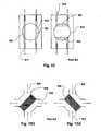
- FIGS. 1A through 1Ea number of alternative designs for four-way valves have been developed for blood circuits.
- U.S. Pat. No. 5,894,011discloses a valve that swaps the connections between pairs of lines 905 and 906 via a pair of rotatably connected disks 901 and 902, each of which supports one of the pairs of lines 905 and 906. A seal must be maintained between the disks 901 and 902 and between the respective lines.
- the deviceis intended to be operated manually.
- FIG. 1Banother four-way valve, disclosed in U.S. Pat. No. 5,605,630 , which has been proposed for use in blood lines, has a rotating wheel 910 with channels 911 and 912 defined between the wheel 910 and the inside of a housing 913. When the wheel is rotated, the channels 911 and 912 shift to join a different pair of lines. This device also has seals.
- FIG. 1Canother arrangement is proposed in U.S. Pat. No. 6,177,049 .
- This devicehas a rotating component 915 with channels 921 and 922 defined within it. As the rotating component 915 is rotated, the channels defined between pairs of lines 917 and 919 change from parallel lines joining one set of corresponding lines to U-shaped channels joining a different set.
- FIGS. 1D1 and 1D2a design, disclosed in U.S. Pat. No. 4,885,087 , is very similar to that of FIG. 1B .
- This designhas a rotator 925 that connects different pairs of lines depending on the position thereby defining two different sets of possible flow channels 926 and 929 or 927 and 931.
- valvesare not hermetically sealed. Any seal can be compromised, particularly by microorganisms. Thus, each of the foregoing designs suffers from that drawback. Also, many are expensive and do not lend themselves to automation.
- FIG. 1Eanother type of four-way valve is formed by interconnecting two tubes 937 and 938 with crossover lines 935 and 936.
- This designis disclosed in U.S. Pat. No. 6,189,388 (Hereafter, "U.S. Pat. No. '388").
- Tube pinching actuators 941-944are used to force fluid through different channels, depending on which actuators are closed.
- This deviceprovides a hermetic seal and can be fairly inexpensive, but in a given configuration, significant no-flow areas are defined. These dead spaces can lead to the coagulation of blood, which is undesirable. Also, the interconnection of tubes in this does not lend itself to automated manufacturing.
- the object of the inventionis a Glood Flow reversing device according to claim 1.
- Figs. 1A, 1B , 1C, 1D1, 1D2 , and 1Eillustrate various flow reversing devices according to the prior art.
- Fig. 2Aillustrates a flow circuit including a blood treatment machine and a sensor module.
- Fig. 2Billustrates a flow reversing portion of the blood treatment machine of Fig. 2A .
- Fig. 3Aillustrates a flow circuit including a blood treatment machine, a flow reversing module.
- Fig. 3Billustrates features of the flow reversing module of Fig. 3A .
- Fig. 3Cillustrates a flow circuit including a blood treatment machine, a flow reversing module, and a sensor module.
- Fig. 3Dillustrates details of a sensor module.
- Fig. 3Eillustrates a detail of a flow circuit with a flow reversing module and separate sensor modules.
- Fig. 4Aillustrates a portion of a fluid circuit that is interoperable with an actuator to form a flow reversing device.
- Fig. 4Billustrates an actuator interoperable with the fluid circuit portion illustrated in Fig. 4A .
- Figs 5A and 5Billustrate two operating modes of a flow reverser defined by the combination of the devices of Figs. 4A and 4B .
- Fig. 6illustrate a flow reversing actuator according to an alternative embodiment to that of Figs. 4A, 4B , 5A, and 5B .
- Fig. 7illustrates a flow reversing device according to an alternative embodiment to that of Figs. 4A, 4B , 5A, and 5B .
- Fig. 8Aillustrates a sensor module embedded in a soft outer casing.
- Fig. 8Billustrates a compact longitudinal reversing module.
- Figs. 9A-9Cillustrate a first embodiment of a fluid circuit portion and an actuator for providing a compact longitudinal flow reverser.
- Figs. 10A and 10Billustrate a second embodiment of an actuator for providing a compact longitudinal flow reverser.
- Fig. 11is a flow chart for describing a control embodiment in which blood flow is reversed according to multiple schedules.
- Fig. 12is a time plot of blood flow for use in describing the control regime of Fig. 11 .
- Fig. 13is an illustration of stagnant flow regions for illustrating the flow control regime of Figs. 11 and 12 .
- Figs. 14A and 14Billustrate control responses to air detection, according to an embodiment of the invention.
- a patient 130is connected by an access 139 to a blood processing machine 315.
- the latterdraws blood through an arterial blood line 305 and returns treated blood to the patient 130 through a venous blood line 307.
- the blood processing machine 315may be any treatment device such as a hemodialysis machine, a hemofiltration machine, an infusion pump (in which case no arterial line 305 would be present), etc.
- Access 139may consist of various devices such as a fistula (not shown) and catheter (not shown) combination or other type of access which may be disconnected by various means.
- a cathetermay be withdrawn from a fistula (not shown) and/or the catheter (not shown) disconnected from the arterial 307 and venous 305 lines by means of a luer connector (not shown).
- a luer connectornot shown
- One or more bubble or air sensorsare provided in a sensor module 311.
- the sensor module 311is connected to the blood processing machine 315 by means of a signal line 302.
- the signal line 302applies a signal indicating the presence of air or bubbles in one or both of the arterial 307 and venous 305 lines.
- the sensor module 311may be lightweight snap-on module that clamps onto the arterial 307 and venous 305 lines. As is common in blood treatment systems, the arterial 307 and venous 305 lines are clear plastic such as PVC.
- the sensor module 311may also include a sensor to indicate the presence of blood in the arterial 307 and venous 305 lines as well. The latter signal may be used for indicating and controlling a transition from a priming mode where the arterial 307 and venous 305 lines carry sterile fluid to a treatment mode where the arterial 307 and venous 305 lines carry blood.
- the blood processing machine 315includes, along with various other hardware elements, a flow reversing valve 327.
- the flow reversing valve 327is controlled by an electronic controller 323 to cause the flow through the arterial 307 and venous 305 lines to reverse.
- the flowmay be as indicated by arrows 301A and during a test mode, in which flow is reversed, blood flow may be as indicated by arrows 301B.
- the flow of blood on the other side of the reversing valve 327may remain as indicated by arrows 301C.
- the reversing valve 327is periodically actuated to place the reversing valve 327 in the test mode. This generates a negative gage pressure in the venous line 305. If any leaks are present in the venous line 305 between the patient 130 and the sensor module 311, air will infiltrate the venous line 305 and be detected by the air or bubble detector within the sensor module 311. The resulting signal may be applied to the controller 323.
- the controller 323may be configured to respond by controlling one or more line clamps as indicated at 317 to stop the flow of blood and trigger an over-pressure alarm in the blood processing machine 315 if the latter is provided with one. The controller may also activate an alarm (not shown).
- the controllermay alternatively maintain the test mode to continue flow in the reversed direction in which case, if the blood processing machine 315 is provided with an internal air or bubble detector (not shown), the latter will be triggered by the infiltrating air as if the air had been drawn by the arterial line in the first instance.
- a flow reversing valve 327is illustrated in Fig. 2B
- alternative mechanisms for generating a negative pressure in the venous line 305are discussed in the references in the instant specification.
- one line clamp 317is illustrated, more clamps may be employed to prevent the loss of blood.
- a clampmay be provided in the venous line 305.
- the use of a sensor module 311 as illustratedallows the sensors to be located close to the patient. Consequently, the system can respond quickly to a disconnection of the arterial 307 or venous 305 lines.
- One of the common types of leaks the system may protect againstis an improperly installed or defective connection between the venous 305 or arterial 307 line and the catheter (not shown).
- a combined flow reversing and sensor module 333houses a flow reversing valve 351 and at least one sensor 352A. Flow through venous 325 and arterial 327 lines may be reversed in portions 337 and 335, respectively, by reversing the flow reversing valve 351.
- the sensor 352Amay include a bubble or air sensor, a blood sensor, or both.
- the sensor module 333 or any of the other sensor modules described hereinmay include other types of sensors such as pressure sensors to detect a loss of patency at any point in the system.
- the blood or air (or bubble) sensorsmay include non-wetted conductivity sensors or non-wetted conductivity cells such as optical (opacity or hue) sensors or any sensor suitable for detecting the presence of air or blood in a clear liquid.
- the sensor modulemay also be used to detect other properties or conditions near the patient access such as a sudden acceleration (by means of an accelerometer) due to detachment and subsequent falling out of a catheter, for example.
- An additional sensor 352Bwhich may be identical to sensor 352A, may be employed to provide an indication of air infiltration during normal operation in a forward blood-flow direction.
- a controller 349may be provided to periodically control the flow reversing valve 351.
- the controllermay activate a line clamp 326.
- the controllermay respond to the detection of air in the same manner as described with respect to the foregoing embodiments or as described in the references incorporated in the instant specification, for example, by clamping the line.
- a signal line 329may be provided to transmit detector and/or controller signals to the blood processing machine 320.
- Blood processing machine 320may be similar to that described with reference to the previous embodiments (e.g. 315 in Figs. 2A and 2B ), but preferably it does not include the reversing valve 351.
- the flowin a normal treatment mode, the flow may be as indicated by arrows 301A and during a test mode, in which flow is reversed; blood flow may be as indicated by arrows 301B.
- blood flowmay be as indicated by arrows 301B.
- the flow of blood on the other side of the reversing valve 351may remain as indicated by arrows 301C.
- the blood processing machine 320is linked by venous 373 and arterial 375 blood lines to a flow reversing module 370.
- a sensor module 377is located close to the access 139 and is coupled to the reversing module 370 by a signal line 378.
- Venous 374A and arterial 376A lineslink the reversing module 370 to the access 139 for supply and return flows of blood (with reference to the patient 130), respectively.
- Portions of venous 374B and arterial 376B linespass through the sensor module 377 to the access 139.
- the configuration of Fig. 3Cas in the configuration of Figs.
- FIG. 2A and 2Ballows the sensor module 377 to be located close to the patient 130 and for the reversing module 370 to be retrofitted to a blood treatment machine 315 that is otherwise not configured for leak detection in the fashion described.
- Figs. 3A-3Care attractive for retrofit applications where leak detection capability is to be added to a blood processing machine 315 otherwise not configured for it.
- the flow reversing module 370may be identical to that shown in Fig. 3B .
- the sensor(s) 352may or may not be present to protect against leaks in the portions of the venous and arterial lines 374A and 376A as well as the portions 374B and 376B which are protected by sensors in the sensor module 377.
- signal line 378 or any of the foregoing signal linesmay represent wireless links, acoustical signal links, or any suitable means of communication.
- the various devicesmay be powered by battery or by electrical lines.
- a sensor module 380has features which may be employed in sensor modules 311 ( Fig. 2A ) and 377 ( Fig. 3C ) described above.
- Air detectors 401 and 407detect air passing through lines 374 and 376, respectively.
- Blood sensors 403 and 405may be included in the sensor module 380 to detect blood in lines 374 and 376, respectively.
- the sensor module 380only contains sensors for a single line 374, which is preferably the venous line of the foregoing embodiments.
- the entire sensor module 380is connected around a single line 374, which is preferably the venous line of the foregoing embodiments.
- both linesmay be provided with separate sensor modules 390A and 390B in an alternative embodiment as illustrated at Fig. 3E .
- two adjacent flow linesmay be protected by a single air detector or blood detector or both.
- a key 409 of any desired shapemay be placed on one of the lines 374 or 376 which fits into a slot 411 and engages a detector 410 to indicate its proper insertion into the slot 411.
- the key 409 and slot 411ensure that if only one line 374 is protected by air sensor 401, that it is the venous line. Otherwise the protection system wherein flow is reversed to indicate a leak would serve no purpose.
- the detector 410may send a signal along the signal line 378 to indicate proper insertion. A failure of proper insertion while attempting to operate the system may cause the system to generate an alarm.
- a door 406may be closed over the lines 374 and/or 376 to lock them in place. Electronic equivalents of key 409 and sensor 410 may also be provided.
- a portion of a fluid circuit 224includes a toroidal portion 226 with ports A, B, C, and D linked by segments 221A, 221B, 221C, and 221D as illustrated.
- Fluid lines 203, 205, 207, and 209connect with respective ones of ports A, B, C, and D.
- the toroidal portion and portions of fluid lines 203, 205, 207, and 209fit into channels 211, 215, 211, and 217 of an actuator 221.
- the actuator 221contains a rotatable clamp 222 with two edges 238 and 237 which selectively pinch segments 221A, 221B, 221C, and 221D between the edges 238 and 237 and edges 231, 229, 235, and 233 of the actuator 221, respectively as illustrated in Figs. 5A and 5B .
- the toroidal portion 226may be of a compliant and stretchable material that permits it to be forced into position in the actuator 221 and partly deformed as illustrated.
- the clamp 22may be in the neutral position illustrated in Fig. 4B when this is done.
- segments 221B and 221Dare clamped closed allowing a flow between line 209 to 207 and from line 205 to line 203 as indicated by arrows 225A and 227A.
- segment 221Bis pinched between edges 238 and 231 while segment 221D is pinched between edges 237 and 235.
- the path of lines 209 to 207may correspond to flow through the venous lines of the previous embodiments.
- line 209may correspond to line 325 and line 207 to line 337.
- the path of lines 205 to 203may correspond to flow through the arterial lines of the previous embodiments.
- line 205may correspond to line 335 and line 203 to line 329.
- the flowmay then provide for normal blood flow for treatment by allowing line 207 to flow blood to a patient and return through line 205 to pass through the flow reverser back to a blood treatment machine.
- Fig. 5Bwhen clamp 222 is in a first position indicated in Fig. 5B , segments 221A and 221C are clamped closed allowing a flow between line 209 to 205 and from line 207 to line 203 as indicated by arrows 225B and 227B.
- the flowmay then provide for reverse blood flow for testing by allowing line 205 to flow blood to a patient and return through line 207 to pass through the flow reverser back to a blood treatment machine.
- This results in a negative pressure in line 207whereupon if any disconnections or leaks occur, air will be drawn into line 207 which may be revealed by a sensor, as discussed with reference to the figures above.
- a clamp 427may be passively mounted on a door 424 and engaged with a drive bolt 443 in a chassis portion 421 of a flow reverser.
- the drive bolt 443may fit as a key in a recess 441 thereby driving the clamp.
- the closure of the door 424may be indicated by a detector which may send a signal to a controller permitting the drive bolt 443 to be operated according to the configuration of a controller (e.g., 349 of Fig. 3B ).
- respective clamps 451A, 451B, 451C, and 451Dmay pinch respective portions of the flow circuit toroidal portion 226 by means of a shaped boss 449 that fits into the center of the toroidal portion 226.
- the claims 451A, 451B, 451C, and 451Dmay be operated by respective drives such as solenoids (not shown) or coupled to be operable with one or two drives as desired.
- the flow reverser or sensor module 379may be fitted into a soft shell 501.
- the lattermay have a shape such as a teddy bear or other stuffed animal or ornament.
- the flow reverseris of a compact longitudinal shape with the lines 667 and 669 leading to the blood treatment machine stemming from one end and the lines and the lines 663 and 665 leading to the patient access stemming from the opposite end. This may allow the flow reverser 661 to lie close to the patient access and self-orient in a comfortable and unobtrusive manner.
- two Y-junctions 503 and 505may be connected to a patient access and two other Y-junctions may be connected to a blood treatment machine or remainder thereof.
- Two double-edged clamps 519 and 521are driven by a double-axis motor drive 527 that rotates one clamp 519 in one direction and the other clamp 521 in the opposite direction, for example by providing that one clamp is connected to the stator and one connected to the rotor of the motor. It is contemplated that a reduction drive would be employed to increase the torque of the primary motor within the drive 527 and allow a small motor (not shown separately) to be used.
- a support stalk 502holds the drive 527 so that it is free to rotate with respect to it, thereby providing a mounting to a housing such as illustrated in Fig. 8B .
- Each segment 511, 513, 515, and 517may be selectively pinched by as illustrated in Figs. 9B and 9C to provide for forward and reverse flow between one pair of junctions 505/503 or 509/507.
- the clampsmay be tapered to provide a high clamping pressure as indicated at 535, 533, 523, and 525 and similarly on portions opposite the edges indicated at 535, 533, 523, and 525.
- tubing structure of Fig. 9Awhich includes parallel segments 511, 513, 515, and 517, and the four Y-junctions 503 and 505, 507, and 509, is toroidal in shape, which can be confirmed by inspection.
- a planar projectionthat is, a mapping or projection, as of a shadow, onto a plane, as of a shadow onto a surface
- FIG. 10A and 10Banother flow reversing device using a fluid circuit portion as illustrated in Fig. 9A producing four parallel segments 511, 513, 515, and 517 is driven by a linear drive (not shown) that moves a stalk 607 along an axis thereof.
- a linear drive(not shown) that moves a stalk 607 along an axis thereof.
- Cams 617 and 619are forced into an opposing pair of tube segments 605 and 611 when a large diameter portion 627 of the stalk 607 is forced between the cams 617 and 619 by pushing the stalk 607 in a first direction (to the left).
- Cams 617 and 619are forced into an opposing pair of tube segments 633 and 635 when a large diameter portion 627 of the stalk 607 is forced between the cams 610 and 621 by pushing the stalk 607 in a second opposite direction (to the right).
- the segmentsmay be held in position by a frame of two portions 613 and 615 which close around a cam frame 607.
- Edges 609 and 611are provided to amplify the pinching stress and cooperative with cams 617 and 619 to clamp the tubes segments 603 and 609.
- an operating regimenbegins with a priming of a fluid circuit at step S10.
- the priming modeis initiated by a priming command being received by the flow reverser controller at step S10.
- the flow reverser controllerplaces the flow reverser in forward mode so that fluid is pumped in a single direction.
- the controllermay be configured to operate for flow in a single direction continuously as long as no blood is detected by blood sensors in the sensor module or in the blood treatment machine.
- the pumpmay be operated at step S20 for a desired period of time to prime the blood circuit and other portions of the fluid circuit used for treatment.
- the operatormay halt the pump, clamp various lines, and make certain connections in preparation for treatment and restart the pump. All these steps are assumed to fall within step S20.
- step S30When the flow reverser controller detects blood in step S25, control flow exits to step S30 and flow continues in the same direction for a specified period of time which may be proportional to the mass flow rate of blood.
- the bloodwill ordinarily be detected because of the connection changes of the operator who has determined that the system is adequately primed and has remade connections as required. This may also be an automated process as well depending on the blood processing system and the level of automation.
- the flow reverser controlmay go into an operating mode where it periodically reverses flow 830 for a fixed interval test cycle 820 to generate a temporary negative pressure and reverse flow to test the venous line and then returns to forward operation 835.
- test cycle 820 intervalwill be shorter than the normal forward treatment 825 interval.
- short duration reverse cycles 810are a higher frequency may be included to clear the dead legs of the flow reversing device.
- the shaded regions 855 in the embodiment of Figs. 5A and 5B in the normal flow directionrepresent areas with no flow. If the blood in these regions is allowed to stagnate for an extended time, clotting may occur. To help prevent this, the flow may be reversed for very short intervals to cause a flow in these otherwise continuously non-flow regions 855.
- a train of such dead-leg clearing cyclesis shown in Fig. 12 at 810.
- the cyclical operation of Fig. 12may continue until a treatment is completed or until air is detected (or some other malfunction causes treatment to be terminated).
- the flow reversing controllerit is desirable for the flow reversing controller to respond to air detection in a manner that ensures an appropriate response without some sort of control connection or control collaboration between the flow reversing module (e.g. 370, Fig. 3C ) and the blood treatment machine 320.
- the flow reversing module control's 349 responseshould ensure appropriate action.
- step S45Aa response S45A for step S45, when air is detected at step S40, the blood lines may be clamped at step S60 to induce a high pressure in the blood treatment machine which in most type of blood treatment machines would trigger a shutdown and error indication by the machine.
- Thismay be provided by means of a clamp as indicated at 326 or 317 in Figs. 3B and 2B respectively, for example.
- another response for step S45is step S45A in which a shutdown by the main processing machine is induced in step S65 to continue operating in reverse mode until the air that was detected by the flow reversing module triggers an air detection by the blood processing machine.
- the reverse cyclemay be kept to a minimum duration.
- this durationis established to provide the minimum volume displacement needed to cause any air bubbles leaking into the blood line to reach the air sensor in the sensor module.
- Thismay be established in the flow reverser by means of an input from a user or by calculating from a measured flow rate.
- a flow rate sensormay be included in the flow reversing module and the controller configured to calculate the amount of time, based on flow rate, to ensure the minimum volume is displaced.
Landscapes
- Health & Medical Sciences (AREA)
- Heart & Thoracic Surgery (AREA)
- Vascular Medicine (AREA)
- Animal Behavior & Ethology (AREA)
- Public Health (AREA)
- Biomedical Technology (AREA)
- Hematology (AREA)
- Life Sciences & Earth Sciences (AREA)
- Engineering & Computer Science (AREA)
- General Health & Medical Sciences (AREA)
- Anesthesiology (AREA)
- Veterinary Medicine (AREA)
- Cardiology (AREA)
- Pulmonology (AREA)
- External Artificial Organs (AREA)
- Infusion, Injection, And Reservoir Apparatuses (AREA)
- Investigating Or Analysing Biological Materials (AREA)
Abstract
Description
- The present invention relates to the detection of leaks (including needle-disconnects and other causes of loss of integrity) in extracorporeal blood circuits and more particularly to the application of air infiltration detection techniques to the detection of leaks in positive pressure return lines.
- Many medical procedures involve the extraction and replacement of flowing blood from, and back into, a donor or patient. The reasons for doing this vary, but generally, they involve subjecting the blood to some process that cannot be carried out inside the body. When the blood is outside the patient it is conducted through machinery that processes the blood. The various processes include, but are not limited to, hemodialysis, hemofiltration, hemodiafiltration, blood and blood component collection, plasmaphresis, aphresis, and blood oxygenation.
- One technique for extracorporeal blood processing employs a single "access," for example a single needle in the vein of the patient or a fistula. A volume of blood is cyclically drawn through the access at one time, processed, and then returned through the same access at another time. Single access systems are uncommon because they limit the rate of processing to half the capacity permitted by the access. As a result, two-access systems, in which blood is drawn from a first access, called an arterial access, and returned through a second access, called a venous access, are much faster and more common. These accesses include catheters, catheters with subcutaneous ports, fistulas, and grafts.
- The processes listed above, and others, often involve the movement of large amounts of blood at a very high rate. For example, 500 ml. of blood may be drawn out and replaced every minute, which is about 5% of the patient's entire supply. If a leak occurs in such a system, the patient could be drained of enough blood in a few minutes to cause loss of consciousness with death following soon thereafter. As a result, such extracorporeal blood circuits are normally used in very safe environments, such as hospitals and treatment centers, and attended by highly trained technicians and doctors nearby. Even with close supervision, a number of deaths occur in the United States every year due to undue blood loss from leaks.
- Leaks present a very real risk. Leaks can occur for various reasons, among them: extraction of a needle, disconnection of a luer, poor manufacture of components, cuts in tubing, and leaks in a catheter. However, in terms of current technology, the most reliable solution to this risk, that of direct and constant trained supervision in a safe environment, has an enormous negative impact on the lifestyles of patients who require frequent treatment and on labor requirements of the institutions performing such therapies. Thus, there is a perennial need in the art for ultra-safe systems that can be used in a non-clinical setting and/or without the need for highly trained and expensive staff. Currently, there is great interest in ways of providing systems for patients to use at home. One of the risks for such systems is the danger of leaks. As a result, a number of companies have dedicated resources to the solution of the problem of leak detection.
- In single-access systems, loss of blood through the patient access and blood circuit can be indirectly detected by detecting the infiltration of air during the draw cycle. Air is typically detected using an ultrasonic air detector on the tubing line, which detects air bubbles in the blood. The detection of air bubbles triggers the system to halt the pump and clamp the line to prevent air bubbles from being injected into the patient. Examples of such systems are described in
U.S. Pat. Nos. 3,985,134 ,4,614,590 , and5,120,303 . - While detection of air infiltration is a reliable technique for detecting leaks in single access systems, the more attractive two-access systems, in which blood is drawn continuously from one access and returned continuously through another, present problems. While a disconnection or leak in the draw line can be sensed by detecting air infiltration, just as with the single needle system, a leak in the return line cannot be so detected. This problem has been addressed in a number of different ways, some of which are generally accepted in the industry.
- The first level of protection against return line blood loss is the use of locking luers on all connections, as described in International Standard ISO 594-2 which help to minimize the possibility of spontaneous disconnection during treatment. Care in the connection.and taping of lines to the patient's bodies is also a known strategy for minimizing this risk.
- A higher level of protection is the provision of venous pressure monitoring, which detects a precipitous decrease in the venous line pressure. This technique is outlined in International Standard IEC 60601-2-16. This approach, although providing some additional protection, is not very robust, because most of the pressure loss in the venous line is in the needle used to access the patient. There is very little pressure change in the venous return line that can be detected in the event of a disconnection, so long as the needle remains attached to the return line. Thus, the pressure signal is very weak. The signal is no stronger for small leaks in the return line, where the pressure changes are too small to be detected with any reliability. One way to compensate for the low pressure signal is to make the system more sensitive, as described in
U.S. Pat. No. 6,221,040 , but this strategy can cause many false positives. It is inevitable that the sensitivity of the system will have to be traded against the burden of monitoring false alarms. Inevitably this leads to compromises in safety. In addition, pressure sensing methods cannot be used at all for detecting small leaks. - Yet another approach, described for example in
PCT application US98/19266 - Still another device for detecting leaks is described in
U.S. Pat. No. 6,044,691 . According to the description, the circuit is checked for leaks prior to the treatment operation. For example, a heated fluid may be run through the circuit and its leakage detected by means of a thermistor. The weakness of this approach is immediately apparent: there is no assurance that the system's integrity will persist, throughout the treatment cycle, as confirmed by the pre-treatment test. Thus, this method also fails to address the entire risk. - Yet another device for checking for leaks in return lines is described in
U.S. Pat. No. 6,090,048 . In the disclosed system, a pressure signal is sensed at the access and used to infer its integrity. The pressure wave may be the patient's pulse or it may be artificially generated by the pump. This approach cannot detect small leaks and is not very sensitive unless powerful pressure waves are.used, in which case the effect can produce considerable discomfort in the patient. - Clearly detection of leaks by prior art methods fails to reduce the risk of dangerous blood loss to an acceptable level. In general, the risk of leakage-related deaths increases with the decrease in medical staff per patient driven by the high cost of trained staff. Currently, with lower staffing levels comes the increased risk of unattended leaks. Thus, there has been, and continues to be, a need in the prior art for a foolproof approach to detection of a return line leak or disconnection.
- In an area unrelated to leak detection,
U.S. Pat. No. 6,177,049 B1 suggests the idea of reversing the direction of blood flow for purposes of patency testing. The patent also states that flow reversal may be used to improve patency by clearing obstructed flow. US Patent 6,572,576 discusses various embodiments of a blood treatment device where blood flow is reversed to provide leak detection. According to the inventions described, a leak detector effective to ensure detection of leaks in the venous blood line (the line returning blood to the patient) is provided by periodically generating a negative pressure, which may be brief or at a 50% duty cycle, in the blood return line. This draws air into the venous line which can be revealed by an air sensor in the blood treatment machine. During the negative pressure cycle, any air drawn in the venous blood line is detected, the system is shut down and an alarm generated.- Hemofiltration, dialysis, hemodiafiltration, and other extracorporeal blood treatments may employ flow selector valves such as Y-valves, four-way valves, and other such devices for redirecting the flow of blood and other fluids such as replacement fluids. For example, the direction of the flow of blood through certain types of filters may be reversed repeatedly to prevent coagulation of blood in regions where the mean flow slows to very low rates. For example, where blood is circulated through tubular media in the context of a dialysis filter, it has been proposed that blood may coagulate on the surface of the inlet header leading to the progressive coagulation of blood.
U.S. Pat. No. 5,605,630 , proposes occasionally reversing the flow of blood through the filter. A four-way valve is proposed for changing over the flow direction. - In other references, the idea of reversing the flow of blood through a tubular media filter is discussed in connection with other issues. For example, in
U.S. Pat. No. 5,894,011 , the known technique of switching access lines in the patient to improve the flow through an occluded fistula is automated by the addition of a four-way valve on the patient-side blood circuit. In single-access systems in general, for example as described inU.S. Pat. No. 5,120,303 , flow is conventionally reversed through the filter during each draw/return cycle. In the '303 reference, the specification observes that the efficiency of filtration is increased due to the double-passing of the same blood through the filter; that is, each volume of drawn blood is filtered twice. Yet another reference,U.S. Pat. No. 6,189,388 B1 , discusses reversing the flow direction of blood through the patient access occasionally in order to quantify an undesirable short-circuit effect that attends their long term use. Still anotherU.S. Pat. No. 6,177,049 B1 suggests reversing flow through the draw access before treatment while an observer is present to test the accesses for patency or to clear blockage in the accesses. - Referring to
FIGS. 1A through 1E , a number of alternative designs for four-way valves have been developed for blood circuits. Referring toFIG. 1A ,U.S. Pat. No. 5,894,011 , discloses a valve that swaps the connections between pairs oflines connected disks lines disks - Referring to
FIG. 1B , another four-way valve, disclosed inU.S. Pat. No. 5,605,630 , which has been proposed for use in blood lines, has arotating wheel 910 withchannels wheel 910 and the inside of ahousing 913. When the wheel is rotated, thechannels - Referring to
FIG. 1C , another arrangement is proposed inU.S. Pat. No. 6,177,049 . This device has arotating component 915 withchannels rotating component 915 is rotated, the channels defined between pairs oflines - Referring to
FIGS. 1D1 and 1D2 , a design, disclosed inU.S. Pat. No. 4,885,087 , is very similar to that ofFIG. 1B . This design has arotator 925 that connects different pairs of lines depending on the position thereby defining two different sets ofpossible flow channels - In all of the above designs, the valves are not hermetically sealed. Any seal can be compromised, particularly by microorganisms. Thus, each of the foregoing designs suffers from that drawback. Also, many are expensive and do not lend themselves to automation.
- Referring to
FIG. 1E , another type of four-way valve is formed by interconnecting twotubes crossover lines U.S. Pat. No. 6,189,388 (Hereafter, "U.S. Pat. No. '388"). Tube pinching actuators 941-944 are used to force fluid through different channels, depending on which actuators are closed. This device provides a hermetic seal and can be fairly inexpensive, but in a given configuration, significant no-flow areas are defined. These dead spaces can lead to the coagulation of blood, which is undesirable. Also, the interconnection of tubes in this does not lend itself to automated manufacturing.
The object of the invention is a Glood Flow reversing device according to claim 1. Figs. 1A, 1B ,1C, 1D1, 1D2 , and1E illustrate various flow reversing devices according to the prior art.Fig. 2A illustrates a flow circuit including a blood treatment machine and a sensor module.Fig. 2B illustrates a flow reversing portion of the blood treatment machine ofFig. 2A .Fig. 3A illustrates a flow circuit including a blood treatment machine, a flow reversing module.Fig. 3B illustrates features of the flow reversing module ofFig. 3A .Fig. 3C illustrates a flow circuit including a blood treatment machine, a flow reversing module, and a sensor module.Fig. 3D illustrates details of a sensor module.Fig. 3E illustrates a detail of a flow circuit with a flow reversing module and separate sensor modules.Fig. 4A illustrates a portion of a fluid circuit that is interoperable with an actuator to form a flow reversing device.Fig. 4B illustrates an actuator interoperable with the fluid circuit portion illustrated inFig. 4A .Figs 5A and 5B illustrate two operating modes of a flow reverser defined by the combination of the devices ofFigs. 4A and 4B .Fig. 6 illustrate a flow reversing actuator according to an alternative embodiment to that ofFigs. 4A, 4B ,5A, and 5B .Fig. 7 illustrates a flow reversing device according to an alternative embodiment to that ofFigs. 4A, 4B ,5A, and 5B .Fig. 8A illustrates a sensor module embedded in a soft outer casing.Fig. 8B illustrates a compact longitudinal reversing module.Figs. 9A-9C illustrate a first embodiment of a fluid circuit portion and an actuator for providing a compact longitudinal flow reverser.Figs. 10A and 10B illustrate a second embodiment of an actuator for providing a compact longitudinal flow reverser.Fig. 11 is a flow chart for describing a control embodiment in which blood flow is reversed according to multiple schedules.Fig. 12 is a time plot of blood flow for use in describing the control regime ofFig. 11 .Fig. 13 is an illustration of stagnant flow regions for illustrating the flow control regime ofFigs. 11 and12 .Figs. 14A and 14B illustrate control responses to air detection, according to an embodiment of the invention.- Referring now to
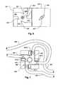
Fig. 2A , apatient 130 is connected by anaccess 139 to ablood processing machine 315. The latter draws blood through anarterial blood line 305 and returns treated blood to thepatient 130 through avenous blood line 307. Theblood processing machine 315 may be any treatment device such as a hemodialysis machine, a hemofiltration machine, an infusion pump (in which case noarterial line 305 would be present), etc. Access 139 may consist of various devices such as a fistula (not shown) and catheter (not shown) combination or other type of access which may be disconnected by various means. For example, a catheter (not shown) may be withdrawn from a fistula (not shown) and/or the catheter (not shown) disconnected from the arterial 307 and venous 305 lines by means of a luer connector (not shown). The above are conventional features of which a variety of alternatives are known.- One or more bubble or air sensors (not shown) are provided in a
sensor module 311. Thesensor module 311 is connected to theblood processing machine 315 by means of asignal line 302. Thesignal line 302 applies a signal indicating the presence of air or bubbles in one or both of the arterial 307 and venous 305 lines. Thesensor module 311 may be lightweight snap-on module that clamps onto the arterial 307 and venous 305 lines. As is common in blood treatment systems, the arterial 307 and venous 305 lines are clear plastic such as PVC. Thesensor module 311 may also include a sensor to indicate the presence of blood in the arterial 307 and venous 305 lines as well. The latter signal may be used for indicating and controlling a transition from a priming mode where the arterial 307 and venous 305 lines carry sterile fluid to a treatment mode where the arterial 307 and venous 305 lines carry blood. - Referring now also to
Fig. 2B , theblood processing machine 315 includes, along with various other hardware elements, aflow reversing valve 327. Theflow reversing valve 327 is controlled by anelectronic controller 323 to cause the flow through the arterial 307 and venous 305 lines to reverse. In a normal treatment mode, the flow may be as indicated byarrows 301A and during a test mode, in which flow is reversed, blood flow may be as indicated byarrows 301B. During both treatment and test modes, the flow of blood on the other side of the reversingvalve 327 may remain as indicated byarrows 301C. - During treatment, the reversing
valve 327 is periodically actuated to place the reversingvalve 327 in the test mode. This generates a negative gage pressure in thevenous line 305. If any leaks are present in thevenous line 305 between the patient 130 and thesensor module 311, air will infiltrate thevenous line 305 and be detected by the air or bubble detector within thesensor module 311. The resulting signal may be applied to thecontroller 323. Thecontroller 323 may be configured to respond by controlling one or more line clamps as indicated at 317 to stop the flow of blood and trigger an over-pressure alarm in theblood processing machine 315 if the latter is provided with one. The controller may also activate an alarm (not shown). The controller may alternatively maintain the test mode to continue flow in the reversed direction in which case, if theblood processing machine 315 is provided with an internal air or bubble detector (not shown), the latter will be triggered by the infiltrating air as if the air had been drawn by the arterial line in the first instance. - Although a
flow reversing valve 327 is illustrated inFig. 2B , alternative mechanisms for generating a negative pressure in thevenous line 305 are discussed in the references in the instant specification. Also, while oneline clamp 317 is illustrated, more clamps may be employed to prevent the loss of blood. For example, a clamp may be provided in thevenous line 305. Note that the use of asensor module 311 as illustrated allows the sensors to be located close to the patient. Consequently, the system can respond quickly to a disconnection of the arterial 307 or venous 305 lines. One of the common types of leaks the system may protect against is an improperly installed or defective connection between the venous 305 or arterial 307 line and the catheter (not shown). - Referring now to
Figs. 3A and 3B , a combined flow reversing andsensor module 333 houses aflow reversing valve 351 and at least onesensor 352A. Flow through venous 325 and arterial 327 lines may be reversed inportions flow reversing valve 351. Thesensor 352A may include a bubble or air sensor, a blood sensor, or both. Thesensor module 333 or any of the other sensor modules described herein may include other types of sensors such as pressure sensors to detect a loss of patency at any point in the system. In the foregoing embodiments, the blood or air (or bubble) sensors may include non-wetted conductivity sensors or non-wetted conductivity cells such as optical (opacity or hue) sensors or any sensor suitable for detecting the presence of air or blood in a clear liquid. The sensor module may also be used to detect other properties or conditions near the patient access such as a sudden acceleration (by means of an accelerometer) due to detachment and subsequent falling out of a catheter, for example. Anadditional sensor 352B, which may be identical tosensor 352A, may be employed to provide an indication of air infiltration during normal operation in a forward blood-flow direction. - A
controller 349 may be provided to periodically control theflow reversing valve 351. The controller may activate aline clamp 326. The controller may respond to the detection of air in the same manner as described with respect to the foregoing embodiments or as described in the references incorporated in the instant specification, for example, by clamping the line. Asignal line 329 may be provided to transmit detector and/or controller signals to theblood processing machine 320.Blood processing machine 320 may be similar to that described with reference to the previous embodiments (e.g. 315 inFigs. 2A and 2B ), but preferably it does not include the reversingvalve 351. As in previous embodiment, in a normal treatment mode, the flow may be as indicated byarrows 301A and during a test mode, in which flow is reversed; blood flow may be as indicated byarrows 301B. During both treatment and test modes, the flow of blood on the other side of the reversingvalve 351 may remain as indicated byarrows 301C. - Referring now to
Fig. 3C , theblood processing machine 320, the same as the one described with reference toFig. 3A , is linked by venous 373 and arterial 375 blood lines to aflow reversing module 370. Asensor module 377 is located close to theaccess 139 and is coupled to the reversingmodule 370 by asignal line 378. Venous 374A and arterial 376A lines link the reversingmodule 370 to theaccess 139 for supply and return flows of blood (with reference to the patient 130), respectively. Portions of venous 374B and arterial 376B lines pass through thesensor module 377 to theaccess 139. The configuration ofFig. 3C , as in the configuration ofFigs. 2A and 2B allows thesensor module 377 to be located close to thepatient 130 and for the reversingmodule 370 to be retrofitted to ablood treatment machine 315 that is otherwise not configured for leak detection in the fashion described. ThusFigs. 3A-3C are attractive for retrofit applications where leak detection capability is to be added to ablood processing machine 315 otherwise not configured for it. - Internally, the
flow reversing module 370 may be identical to that shown inFig. 3B . The sensor(s) 352 may or may not be present to protect against leaks in the portions of the venous andarterial lines portions sensor module 377. Note also thatsignal line 378 or any of the foregoing signal lines may represent wireless links, acoustical signal links, or any suitable means of communication. Also, the various devices may be powered by battery or by electrical lines. - Referring to
Fig. 3D , asensor module 380 has features which may be employed in sensor modules 311 (Fig. 2A ) and 377 (Fig. 3C ) described above.Air detectors lines Blood sensors sensor module 380 to detect blood inlines sensor module 380 only contains sensors for asingle line 374, which is preferably the venous line of the foregoing embodiments. In yet another embodiment, theentire sensor module 380 is connected around asingle line 374, which is preferably the venous line of the foregoing embodiments. In the latter case, only theupper part 380A is present and theother half 380B on the other side ofline 380C is not present. Note that alternatively, both lines may be provided withseparate sensor modules Fig. 3E . Note also that two adjacent flow lines may be protected by a single air detector or blood detector or both. - A key 409 of any desired shape may be placed on one of the
lines slot 411 and engages adetector 410 to indicate its proper insertion into theslot 411. The key 409 and slot 411 ensure that if only oneline 374 is protected byair sensor 401, that it is the venous line. Otherwise the protection system wherein flow is reversed to indicate a leak would serve no purpose. Thedetector 410 may send a signal along thesignal line 378 to indicate proper insertion. A failure of proper insertion while attempting to operate the system may cause the system to generate an alarm. Adoor 406 may be closed over thelines 374 and/or 376 to lock them in place. Electronic equivalents ofkey 409 andsensor 410 may also be provided. - Referring to
Figs. 4A and 4B , in an embodiment of a compact and reliable flow reversing device, a portion of afluid circuit 224 includes atoroidal portion 226 with ports A, B, C, and D linked bysegments Fluid lines fluid lines channels actuator 221. Theactuator 221 contains arotatable clamp 222 with twoedges segments edges edges actuator 221, respectively as illustrated inFigs. 5A and 5B . - Referring now to
Fig. 5A , thetoroidal portion 226 may be of a compliant and stretchable material that permits it to be forced into position in theactuator 221 and partly deformed as illustrated. The clamp 22 may be in the neutral position illustrated inFig. 4B when this is done. During operation, whenclamp 222 is in a first position indicated inFig. 5A ,segments line 209 to 207 and fromline 205 toline 203 as indicated byarrows segment 221B is pinched betweenedges segment 221D is pinched betweenedges lines 209 to 207 may correspond to flow through the venous lines of the previous embodiments. For example, with reference toFig. 3A ,line 209 may correspond toline 325 andline 207 toline 337. Similarly, the path oflines 205 to 203 may correspond to flow through the arterial lines of the previous embodiments. For example, with reference toFig. 3A ,line 205 may correspond toline 335 andline 203 toline 329. In the configuration ofFig. 5A , the flow may then provide for normal blood flow for treatment by allowingline 207 to flow blood to a patient and return throughline 205 to pass through the flow reverser back to a blood treatment machine. - Referring now to
Fig. 5B , whenclamp 222 is in a first position indicated inFig. 5B ,segments line 209 to 205 and fromline 207 toline 203 as indicated byarrows Fig. 5B , the flow may then provide for reverse blood flow for testing by allowingline 205 to flow blood to a patient and return throughline 207 to pass through the flow reverser back to a blood treatment machine. This results in a negative pressure inline 207 whereupon if any disconnections or leaks occur, air will be drawn intoline 207 which may be revealed by a sensor, as discussed with reference to the figures above. - Referring now to
Figs. 6 and 7 , in alternative embodiments of the flow reverser ofFigs. 5A and 5B aclamp 427 may be passively mounted on adoor 424 and engaged with adrive bolt 443 in achassis portion 421 of a flow reverser. Thedrive bolt 443 may fit as a key in arecess 441 thereby driving the clamp. The closure of thedoor 424 may be indicated by a detector which may send a signal to a controller permitting thedrive bolt 443 to be operated according to the configuration of a controller (e.g., 349 ofFig. 3B ). Instead of a single rotating clamp located at a center of a flow reverser,respective clamps toroidal portion 226 by means of ashaped boss 449 that fits into the center of thetoroidal portion 226. Theclaims - Referring to
Fig. 8A , to permit a flow reverser or sensor module to be placed close to the patient but allow for patient comfort, the flow reverser orsensor module 379 may be fitted into asoft shell 501. The latter may have a shape such as a teddy bear or other stuffed animal or ornament. - Referring to
Fig. 8B , preferably the flow reverser is of a compact longitudinal shape with thelines lines flow reverser 661 to lie close to the patient access and self-orient in a comfortable and unobtrusive manner. - Referring to
Figs. 9A, 9B, and 9C , two Y-junctions clamps axis motor drive 527 that rotates oneclamp 519 in one direction and theother clamp 521 in the opposite direction, for example by providing that one clamp is connected to the stator and one connected to the rotor of the motor. It is contemplated that a reduction drive would be employed to increase the torque of the primary motor within thedrive 527 and allow a small motor (not shown separately) to be used. Asupport stalk 502 holds thedrive 527 so that it is free to rotate with respect to it, thereby providing a mounting to a housing such as illustrated inFig. 8B . Eachsegment Figs. 9B and 9C to provide for forward and reverse flow between one pair ofjunctions 505/503 or 509/507. The clamps may be tapered to provide a high clamping pressure as indicated at 535, 533, 523, and 525 and similarly on portions opposite the edges indicated at 535, 533, 523, and 525. - Note that the tubing structure of
Fig. 9A which includesparallel segments junctions structure parallel segments parallel segments - Referring to
Figs. 10A and 10B , another flow reversing device using a fluid circuit portion as illustrated inFig. 9A producing fourparallel segments stalk 607 along an axis thereof.Cams tube segments large diameter portion 627 of thestalk 607 is forced between thecams stalk 607 in a first direction (to the left).Cams tube segments large diameter portion 627 of thestalk 607 is forced between thecams stalk 607 in a second opposite direction (to the right). The segments may be held in position by a frame of twoportions cam frame 607.Edges cams tubes segments - Referring to
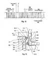
Fig. 11 , an operating regimen begins with a priming of a fluid circuit at step S10. The priming mode is initiated by a priming command being received by the flow reverser controller at step S10. The flow reverser controller places the flow reverser in forward mode so that fluid is pumped in a single direction. The controller may be configured to operate for flow in a single direction continuously as long as no blood is detected by blood sensors in the sensor module or in the blood treatment machine. The pump may be operated at step S20 for a desired period of time to prime the blood circuit and other portions of the fluid circuit used for treatment. At some point during the priming mode, the operator may halt the pump, clamp various lines, and make certain connections in preparation for treatment and restart the pump. All these steps are assumed to fall within step S20. - When the flow reverser controller detects blood in step S25, control flow exits to step S30 and flow continues in the same direction for a specified period of time which may be proportional to the mass flow rate of blood. The blood will ordinarily be detected because of the connection changes of the operator who has determined that the system is adequately primed and has remade connections as required. This may also be an automated process as well depending on the blood processing system and the level of automation. Referring now also to
Fig. 12 , once the initial forward operation period has elapsed at step S30, the flow reverser control may go into an operating mode where it periodically reversesflow 830 for a fixedinterval test cycle 820 to generate a temporary negative pressure and reverse flow to test the venous line and then returns to forwardoperation 835. Generally, thetest cycle 820 interval will be shorter than thenormal forward treatment 825 interval. In addition.to the test cycle, short durationreverse cycles 810 are a higher frequency may be included to clear the dead legs of the flow reversing device. Referring momentarily toFig. 13 , theshaded regions 855 in the embodiment ofFigs. 5A and 5B in the normal flow direction represent areas with no flow. If the blood in these regions is allowed to stagnate for an extended time, clotting may occur. To help prevent this, the flow may be reversed for very short intervals to cause a flow in these otherwise continuouslynon-flow regions 855. A train of such dead-leg clearing cycles is shown inFig. 12 at 810. - Returning to
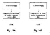
Fig. 11 , the cyclical operation ofFig. 12 may continue until a treatment is completed or until air is detected (or some other malfunction causes treatment to be terminated). For retrofit embodiments of the flow reversing leak detection system such as illustrated inFigs. 3A and3C for example, it is desirable for the flow reversing controller to respond to air detection in a manner that ensures an appropriate response without some sort of control connection or control collaboration between the flow reversing module (e.g. 370,Fig. 3C ) and theblood treatment machine 320. Thus, preferably the flow reversing module control's 349 response should ensure appropriate action. Referring now toFig. 14A , to that end a response S45A for step S45, when air is detected at step S40, the blood lines may be clamped at step S60 to induce a high pressure in the blood treatment machine which in most type of blood treatment machines would trigger a shutdown and error indication by the machine. This may be provided by means of a clamp as indicated at 326 or 317 inFigs. 3B and2B respectively, for example. Referring toFig. 14B , another response for step S45 is step S45A in which a shutdown by the main processing machine is induced in step S65 to continue operating in reverse mode until the air that was detected by the flow reversing module triggers an air detection by the blood processing machine. - Note that by placing the air sensor close to a patient as described in the foregoing embodiments, the reverse cycle may be kept to a minimum duration. Preferably this duration is established to provide the minimum volume displacement needed to cause any air bubbles leaking into the blood line to reach the air sensor in the sensor module. This may be established in the flow reverser by means of an input from a user or by calculating from a measured flow rate. Thus, a flow rate sensor may be included in the flow reversing module and the controller configured to calculate the amount of time, based on flow rate, to ensure the minimum volume is displaced.
Claims (9)
- A blood flow reversing device for blood processing, comprising:a reversing valve (327; 351) configured to reverse blood flow between a treatment apparatus (315; 320) and a patient access (139);a controller (323; 349) configured to control said reversing valve (327; 351) to reverse said blood flow for a first interval at a first frequency and for a second interval at a second frequency, said first frequency being greater than said second frequency.
- The device as in claim 1, wherein said second interval is longer than said first interval.
- The device as in claim 1 or 2, further comprising
a pair of patient-side ports for connection to the patient access (139); and
a pair of treatment-side ports for connection to the treatment apparatus (315; 320);
the reversing valve (327; 351) being configured to allow blood to flow between said patient-side and said treatment-side ports in two selected directions of flow in said patient-side ports, such that blood flow from said patient-side ports and said patient access (139) is selectively reversible. - The device as in claim 3, further comprising an air detector (401), said reversing valve (327; 351) being configured to block blood flow through said treatment-side ports and said controller (323; 349) being configured to control said reversing valve to block said blood flow in response to a detection of air in blood by said air detector (401).
- The device as in one of claims 1 to 4, wherein the reverse valve (327; 351) comprises:a flexible ring-shaped structure (226) defining a central opening surrounded by non-wetted surface thereof;said ring-shaped structure having a wetted surface therewithin in fluid communication with multiple fluid ports (A, B, C, D);an actuator (221) having a pivoting element (222) with two ends, that fits within said ring-shaped structure (226);said actuator (221) having fixed elements with edges (229, 231, 233, 235) that oppose said two ends on respective sides such that when said pivoting element (222) is pivoted in a first direction, it pinches a first two portions of said ring-shaped structure (226) against a first two of said edges (231, 235), said first two portions corresponding to a first two flow passages of said ring-shaped structure (226) and such that when said pivoting element (222) is pivoted in a second direction, it pinches a second two portions of said ring-shaped structure (226) against a second two of said edges (229, 233), said second two portions corresponding to a second two flow passages of said ring-shaped structure (226), a configuration of said ports (A, B, C, D) being such that communication between a first two of said fluid ports (A, B) is blocked while fluid communication between a second two of said fluid ports (B, C) is permitted when said pivoting element (222) is pivoted in said first direction while communication between the second two of said fluid ports (B, C) is blocked while fluid communication between the first two of said fluid ports (A, B) is permitted when said pivoting element (222) is pivoted in said second direction.
- The device as in claim 5, wherein said fixed and pivoting elements are arranged to define a ring-shaped recess into which said ring-shaped structure (226) fits.
- The device as in one of claims 1 to 4, wherein the reverse valve (327; 351) comprises:a flexible valve body (226; 633, 635) linking together, for fluid communication, fluid ports (A, B, C, D) fluidly connected by said valve body (226; 633, 635);said valve body (226; 633, 635) forming a structure that surrounds a first portion of an actuator with at least one first pinching element (222; 449; 627);a second portion of the actuator that slides relative to said first portion;said valve body (226; 633, 635) being at least partly confined within;the second portion of the actuator (221; 607, 613) having at least one second pinching element (229, 231, 233, 235; 451A, 451B, 451C, 451D; 609) opposing said at least one first pinching element (222; 449; 627);in a first configuration, said actuator (221; 607, 613) pinching said valve body (226; 633, 635) such that a first pair of said fluid ports (B, C) are linked for fluid communication while a second pair (A, B) is blocked;in a second configuration, said actuator (221; 607, 613) pinching said valve body (226; 633, 635) such that a second pair of said fluid ports (A, B) are linked for fluid communication while said first pair (B, C) is blocked.
- The device as in one of claims 1 to 4, wherein the reverse valve (327; 351) comprises:a flexible valve body (511, 513, 515, 517) linking together, for fluid communication, fluid ports fluidly connected by said valve body (511, 513, 515, 517);an actuator having first and second clamp elements (519, 521) that are mutually selectively movable in first and second directions;
said actuator pinching said valve body (511, 513, 515, 517) such that a first pair of said fluid ports are linked for fluid communication while a second pair is blocked when said first and second clamp elements (519, 521) are mutually moved in said first direction;
said actuator pinching said valve body (511, 513, 515, 517) such that a second pair of said fluid ports are linked for fluid communication while said first pair is blocked when said first and second clamp elements (519, 521) are mutually moved in said second direction. - The device as of one of claims 5 to 8, further comprising a housing having patient side ones of said fluid ports on a first end and treatment-side ones of said fluid ports on a second end, allowing the device to be located close to the patient access (139) and remote from the treatment apparatus (315; 320).
Applications Claiming Priority (2)
| Application Number | Priority Date | Filing Date | Title |
|---|---|---|---|
| US51812203P | 2003-11-07 | 2003-11-07 | |
| PCT/US2004/036933WO2005046439A2 (en) | 2003-11-07 | 2004-11-05 | Improved methods and apparatus for leak detection in blood processing systems |
Publications (3)
| Publication Number | Publication Date |
|---|---|
| EP1691882A2 EP1691882A2 (en) | 2006-08-23 |
| EP1691882A4 EP1691882A4 (en) | 2009-09-02 |
| EP1691882B1true EP1691882B1 (en) | 2010-09-08 |
Family
ID=34590220
Family Applications (1)
| Application Number | Title | Priority Date | Filing Date |
|---|---|---|---|
| EP04810398AExpired - LifetimeEP1691882B1 (en) | 2003-11-07 | 2004-11-05 | Apparatus for leak detection in blood processing systems |
Country Status (6)
| Country | Link |
|---|---|
| US (3) | US8002727B2 (en) |
| EP (1) | EP1691882B1 (en) |
| JP (1) | JP4416797B2 (en) |
| AT (1) | ATE480291T1 (en) |
| DE (1) | DE602004029077D1 (en) |
| WO (1) | WO2005046439A2 (en) |
Families Citing this family (72)
| Publication number | Priority date | Publication date | Assignee | Title |
|---|---|---|---|---|
| US20030128125A1 (en) | 2002-01-04 | 2003-07-10 | Burbank Jeffrey H. | Method and apparatus for machine error detection by combining multiple sensor inputs |
| US9717840B2 (en) | 2002-01-04 | 2017-08-01 | Nxstage Medical, Inc. | Method and apparatus for machine error detection by combining multiple sensor inputs |
| US10155082B2 (en) | 2002-04-10 | 2018-12-18 | Baxter International Inc. | Enhanced signal detection for access disconnection systems |
| US20040254513A1 (en) | 2002-04-10 | 2004-12-16 | Sherwin Shang | Conductive polymer materials and applications thereof including monitoring and providing effective therapy |
| US9055995B2 (en) | 2002-11-04 | 2015-06-16 | Aspire Bariatrics, Inc. | Method for treating obesity by extracting food |
| US7815629B2 (en) | 2002-11-04 | 2010-10-19 | Deka Products Limited Partnership | Apparatus for treating obesity by extracting food |
| US7740624B2 (en) | 2002-11-04 | 2010-06-22 | Aspiration Medical Technology, Llc | Method for treating obesity by extracting food |
| EP1691882B1 (en) | 2003-11-07 | 2010-09-08 | NxStage Medical, Inc. | Apparatus for leak detection in blood processing systems |
| US20070004996A1 (en)* | 2005-06-20 | 2007-01-04 | Lovejoy David A | Needle disengagement sensing mechanism |
| FR2889451A1 (en)* | 2005-08-08 | 2007-02-09 | Philippe Montillier | Human`s e.g. patient, extracorporeal fluid circulating device for realizing e.g. hemodialysis operation, has leads placed between ends of two tubes, and closing unit closing simultaneously additional tubes or two portions of former tubes |
| US8062285B2 (en)* | 2006-08-03 | 2011-11-22 | Aspire Bariatrics, Llc | Systems and methods for removing ingested material from a stomach |
| US8632513B2 (en) | 2006-08-03 | 2014-01-21 | Aspire Bariatrics, Inc. | Systems and methods for removing ingested material from a stomach |
| US10463778B2 (en) | 2007-02-09 | 2019-11-05 | Baxter International Inc. | Blood treatment machine having electrical heartbeat analysis |
| US8152751B2 (en) | 2007-02-09 | 2012-04-10 | Baxter International Inc. | Acoustic access disconnection systems and methods |
| US8597505B2 (en) | 2007-09-13 | 2013-12-03 | Fresenius Medical Care Holdings, Inc. | Portable dialysis machine |
| US9358331B2 (en) | 2007-09-13 | 2016-06-07 | Fresenius Medical Care Holdings, Inc. | Portable dialysis machine with improved reservoir heating system |
| US8240636B2 (en) | 2009-01-12 | 2012-08-14 | Fresenius Medical Care Holdings, Inc. | Valve system |
| US8535522B2 (en) | 2009-02-12 | 2013-09-17 | Fresenius Medical Care Holdings, Inc. | System and method for detection of disconnection in an extracorporeal blood circuit |
| US8105487B2 (en) | 2007-09-25 | 2012-01-31 | Fresenius Medical Care Holdings, Inc. | Manifolds for use in conducting dialysis |
| US8040493B2 (en) | 2007-10-11 | 2011-10-18 | Fresenius Medical Care Holdings, Inc. | Thermal flow meter |
| US9308307B2 (en) | 2007-09-13 | 2016-04-12 | Fresenius Medical Care Holdings, Inc. | Manifold diaphragms |
| US9011334B2 (en)* | 2007-09-27 | 2015-04-21 | Baxter International Inc. | Access disconnect detection |
| CA3057807C (en) | 2007-11-29 | 2021-04-20 | Thomas P. Robinson | System and method for conducting hemodialysis and hemofiltration |
| AU2008354310B2 (en) | 2008-04-01 | 2014-02-20 | Gambro Lundia Ab | An apparatus and a method for monitoring a vascular access |
| CN102006896B (en)* | 2008-04-15 | 2014-02-19 | 甘布罗伦迪亚股份公司 | blood processing device |
| EP2303356B1 (en) | 2008-06-26 | 2016-03-23 | Gambro Lundia AB | Methods and devices for monitoring the integrity of a fluid connection |
| EP3586946B1 (en) | 2008-10-07 | 2023-03-29 | Fresenius Medical Care Holdings, Inc. | Priming system and method for dialysis systems |
| AU2008363189B2 (en) | 2008-10-22 | 2014-01-16 | Debiotech S.A. | Mems fluid pump with integrated pressure sensor for dysfunction detection |
| EA024555B1 (en) | 2008-10-30 | 2016-09-30 | Фрезениус Медикал Кеа Холдингс, Инк. | Modular, portable dialysis system |
| WO2010114932A1 (en) | 2009-03-31 | 2010-10-07 | Xcorporeal, Inc. | Modular reservoir assembly for a hemodialysis and hemofiltration system |
| EP3689392B1 (en)* | 2009-04-23 | 2024-03-20 | Fresenius Medical Care Deutschland GmbH | Treatment apparatus for withdrawing blood from an extracorporeal blood circuit |
| KR101707701B1 (en) | 2009-06-26 | 2017-02-16 | 감브로 룬디아 아베 | Devices, a computer program product and a method for data extraction |
| DE102009052176A1 (en)* | 2009-11-06 | 2011-05-12 | Ulrich Gmbh & Co. Kg | Branch piece for a fluid delivery system |
| US8753515B2 (en) | 2009-12-05 | 2014-06-17 | Home Dialysis Plus, Ltd. | Dialysis system with ultrafiltration control |
| KR101720823B1 (en) | 2009-12-28 | 2017-03-28 | 감브로 룬디아 아베 | Apparatus and method for prediction of rapid symptomatic blood pressure decrease |
| WO2011122751A1 (en)* | 2010-04-02 | 2011-10-06 | Lee Sang Yub | Liquid medicine administering device for endoscopic surgery, medical controller for liquid medicine, and liquid medicine administering device for endoscopic surgery comprising same |
| US8501009B2 (en) | 2010-06-07 | 2013-08-06 | State Of Oregon Acting By And Through The State Board Of Higher Education On Behalf Of Oregon State University | Fluid purification system |
| EP2543404A1 (en) | 2011-07-04 | 2013-01-09 | Debiotech S.A. | Method and system for detecting malfunction of a mems micropump |
| JP6088499B2 (en) | 2011-06-23 | 2017-03-01 | デバイオテック・ソシエテ・アノニム | Method and system for malfunction detection of MEMS micropumps |
| DE112012003387T5 (en) | 2011-08-15 | 2014-04-30 | Nxstage Medical, Inc. | Devices, methods and systems for detecting leaks in medical devices |
| US9375561B2 (en)* | 2011-09-02 | 2016-06-28 | Carefusion 303, Inc. | Self-flushing valve |
| JP2014533133A (en) | 2011-10-07 | 2014-12-11 | ホーム・ダイアリシス・プラス・リミテッドHome DialysisPlus, Ltd. | Purification of heat exchange fluids for dialysis systems |
| ITRM20120013A1 (en)* | 2012-01-16 | 2013-07-17 | Nicola Grandolfo | EXTERNAL TERMINAL DEVICE FOR PERMANENT CATHETER WITH INSULATION OF A LIQUID FLOW |
| US9415151B2 (en)* | 2012-09-25 | 2016-08-16 | Fresenius Medical Care Holdings, Inc. | Blood flow reversal valves and related systems and methods |
| JP5869684B2 (en)* | 2012-09-26 | 2016-02-24 | テルモ株式会社 | Controller for life support apparatus and control method thereof |
| US9201036B2 (en) | 2012-12-21 | 2015-12-01 | Fresenius Medical Care Holdings, Inc. | Method and system of monitoring electrolyte levels and composition using capacitance or induction |
| US9157786B2 (en) | 2012-12-24 | 2015-10-13 | Fresenius Medical Care Holdings, Inc. | Load suspension and weighing system for a dialysis machine reservoir |
| US10085866B2 (en) | 2013-02-23 | 2018-10-02 | Aspire Bariatrics, Inc. | Apparatus and method for draining material from a stomach |
| AU2014234479B2 (en) | 2013-03-20 | 2018-08-02 | Gambro Lundia Ab | Monitoring of cardiac arrest in a patient connected to an extracorporeal blood processing apparatus |
| US9354640B2 (en) | 2013-11-11 | 2016-05-31 | Fresenius Medical Care Holdings, Inc. | Smart actuator for valve |
| JP6433132B2 (en)* | 2014-02-27 | 2018-12-05 | テルモ株式会社 | Extracorporeal circulation management device, extracorporeal circulation device, and control method for extracorporeal circulation management device |
| EP3838308A1 (en) | 2014-04-29 | 2021-06-23 | Outset Medical, Inc. | Dialysis system and methods |
| US10953215B2 (en)* | 2015-04-08 | 2021-03-23 | Dale Medical Products, Inc. | Non-luer compatible administration port |
| US9889244B2 (en) | 2015-12-17 | 2018-02-13 | Fresenius Medical Care Holdings, Inc. | System and method for controlling venous air recovery in a portable dialysis system |
| US10413654B2 (en) | 2015-12-22 | 2019-09-17 | Baxter International Inc. | Access disconnection system and method using signal metrics |
| CN108778361B (en) | 2016-03-08 | 2021-09-28 | 费森尤斯医疗保健控股公司 | Method and system for detecting an occlusion in a blood circuit of a dialysis system |
| US10987460B2 (en) | 2016-03-08 | 2021-04-27 | Fresenius Medical Care Holdings, Inc. | Methods and systems of generating rapidly varying pressure amplitudes in fluidic circuits in a dialysis treatment system |
| EP3500317B1 (en) | 2016-08-19 | 2022-02-23 | Outset Medical, Inc. | Peritoneal dialysis system and methods |
| JP6927232B2 (en)* | 2016-11-14 | 2021-08-25 | ニプロ株式会社 | Flow path switching device |
| US10561778B2 (en) | 2017-03-02 | 2020-02-18 | Fresenius Medical Care Holdings, Inc. | Split reservoir bags and method of using split reservoir bags to improve the heating and generation of dialysate |
| US11426504B2 (en) | 2017-03-29 | 2022-08-30 | Nxstage Medical, Inc. | Flow reversing device |
| US11110214B2 (en) | 2017-04-07 | 2021-09-07 | Fresenius Medical Care Holdings, Inc. | Methods and systems for measuring and heating dialysate |
| EP3799573B1 (en) | 2018-07-30 | 2023-05-10 | Fresenius Medical Care Holdings, Inc. | Valve actuation systems and related methods |
| CA3105974A1 (en) | 2018-07-31 | 2020-02-06 | Fresenius Medical Care Holdings, Inc. | Rotary valves for dialysis systems |
| US12201762B2 (en) | 2018-08-23 | 2025-01-21 | Outset Medical, Inc. | Dialysis system and methods |
| CN113423456B (en) | 2018-12-07 | 2024-03-19 | 费森尤斯医疗保健控股公司 | Rotary valve for managing fluid flow in a medical system |
| US11491007B2 (en) | 2019-02-19 | 2022-11-08 | Twelve, Inc. | Hydraulic delivery systems with flow diversion devices and associated methods |
| WO2020223500A1 (en) | 2019-04-30 | 2020-11-05 | Outset Medical, Inc. | Dialysis system and methods |
| CA3147446A1 (en) | 2019-08-05 | 2021-02-11 | Fresenius Medical Care Holdings, Inc. | Conductivity control systems |
| FR3104441B1 (en) | 2019-12-15 | 2024-10-04 | Ubiplug | Interface device between external equipment and tubes intended to be connected to a patient's system. |
| US11338072B2 (en)* | 2020-04-14 | 2022-05-24 | Fresenius Medical Care Holdings, Inc. | Blood treatment systems and related components and methods |
| IT202300015918A1 (en)* | 2023-07-27 | 2025-01-27 | Federico Nalesso | DEVICE FOR REVERSING BLOOD FLOW IN CENTRAL VENOUS CATHETERS FOR EXTRACORPOREAL PURIFICATION |
Family Cites Families (52)
| Publication number | Priority date | Publication date | Assignee | Title |
|---|---|---|---|---|
| US591870A (en)* | 1897-10-19 | Incubator | ||
| US3744524A (en)* | 1970-09-08 | 1973-07-10 | R Blau | Flexible pinch valve for conveying dry materials and slurries |
| NL158390B (en) | 1973-11-26 | 1978-11-15 | Rhone Poulenc Sa | DEVICE FOR EXTERNAL CIRCULAR DIALYSIS. |
| US4160727A (en) | 1976-02-21 | 1979-07-10 | Foremost-Mckesson, Inc. | Method and apparatus utilizing staged reverse osmosis units for purifying and dispensing water |
| SE423318B (en) | 1980-06-27 | 1982-05-03 | Gambro Ab | MEMO Filtration System |
| US4495067A (en) | 1980-12-02 | 1985-01-22 | Tracor, Inc. | Apparatus for preparation of infusion grade water |
| DE3335744C1 (en) | 1983-10-01 | 1984-12-13 | B. Braun Melsungen Ag, 3508 Melsungen | Dialysis machine |
| US4666598A (en) | 1985-06-25 | 1987-05-19 | Cobe Laboratories, Inc. | Apparatus for use with fluid flow transfer device |
| US4770787A (en) | 1985-06-25 | 1988-09-13 | Cobe Laboratories, Inc. | Method of operating a fluid flow transfer device |
| BE905615R (en) | 1986-09-10 | 1987-04-17 | Hombrouckx Remi O J | METHOD AND EQUIPMENT FOR SINGLE NEEDLE MODIALYSIS. |
| US4885087A (en) | 1986-11-26 | 1989-12-05 | Kopf Henry B | Apparatus for mass transfer involving biological/pharmaceutical media |
| US6835267B1 (en) | 1987-03-27 | 2004-12-28 | Avery Dennison Corporation | Dry paint transfer process and product |
| US4784763A (en) | 1987-07-13 | 1988-11-15 | Labconco Corporation | Water purification machine |
| US5004535A (en) | 1989-04-17 | 1991-04-02 | Aquatec Water Systems Incorporated | Water purification system |
| US5032205A (en) | 1989-05-05 | 1991-07-16 | Wisconsin Alumni Research Foundation | Plasma etching apparatus with surface magnetic fields |
| JPH0674849B2 (en) | 1989-12-21 | 1994-09-21 | 竜 川辺 | Method and device for opening and closing multi-way valve |
| US5032265A (en) | 1990-06-20 | 1991-07-16 | Millipore Corporation | Method and system for producing sterile aqueous solutions |
| EP0544839A4 (en) | 1990-08-20 | 1993-08-11 | Abbott Laboratories | Medical drug formulation and delivery system |
| US5498336A (en)* | 1991-02-22 | 1996-03-12 | Terumo Kabushiki Kaisha | Leukocyte-removing filter and leukocyte-removing apparatus furnished therewith |
| US5259954A (en) | 1991-12-16 | 1993-11-09 | Sepratech, Inc. | Portable intravenous solution preparation apparatus and method |
| DE4218115A1 (en) | 1992-06-02 | 1993-12-09 | Guenter Lauer | Process and treatment device for pure water production |
| GB2276566A (en) | 1993-03-24 | 1994-10-05 | Saitekku Kabushiki Kaisha | Haemodialyser unit |
| JP3254324B2 (en)* | 1994-03-09 | 2002-02-04 | 日本ファーネス工業株式会社 | 4-way flow switching device |
| DE19528907C1 (en) | 1995-08-05 | 1996-11-07 | Fresenius Ag | Haemodynamic parameter measurement equipment for extracorporeal blood circulation appts. |
| SE508374C2 (en) | 1995-09-12 | 1998-09-28 | Gambro Med Tech Ab | Method and apparatus for detecting the condition of a blood vessel access |
| US7144505B2 (en) | 1997-09-18 | 2006-12-05 | Baxter International Inc. | Melt-spun polysulfone semipermeable membranes and methods for making the same |
| US6218441B1 (en) | 1997-09-18 | 2001-04-17 | Timothy B. Meluch | Melt-spun polysulfone semipermeable membranes and methods for making the same |
| US5951870A (en) | 1997-10-21 | 1999-09-14 | Dsu Medical Corporation | Automatic priming of blood sets |
| US6187198B1 (en) | 1997-10-21 | 2001-02-13 | Dsu Medical Corporation | Automatic priming of connected blood sets |
| US6189388B1 (en) | 1997-11-12 | 2001-02-20 | Gambro, Inc. | Access flow monitoring using reversal of normal blood flow |
| US6582385B2 (en) | 1998-02-19 | 2003-06-24 | Nstage Medical, Inc. | Hemofiltration system including ultrafiltrate purification and re-infusion system |
| US6177049B1 (en) | 1998-06-10 | 2001-01-23 | Dsu Medical Corporation | Reversing flow blood processing system |
| US5894011A (en) | 1998-06-24 | 1999-04-13 | Prosl; Frank R. | Flow reversing device for hemodialysis |
| US6044691A (en) | 1998-08-26 | 2000-04-04 | Aksys, Ltd. | Blood tubing set integrity tests for extracorporeal circuits |
| DE19848235C1 (en) | 1998-10-20 | 2000-03-16 | Fresenius Medical Care De Gmbh | Method for monitoring supply to vessel and extra-corporeal blood treatment device for monitoring supply to vessel; inputs blood circulation pressure to computer to calculate values to identify errors in supply during dialysis |
| AUPP790898A0 (en) | 1998-12-23 | 1999-01-28 | Life Therapeutics Limited | Renal dialysis |
| US6319465B1 (en) | 1999-06-03 | 2001-11-20 | Dsu Medical Corporation | Reversing flow blood processing system having reduced clotting potential |
| DE10000186C2 (en) | 2000-01-05 | 2003-09-04 | Sartorius Gmbh | Device and system for crossflow filtration |
| US6515462B2 (en)* | 2000-02-10 | 2003-02-04 | Rohm Co., Ltd. | Power supply device |
| US6308737B1 (en) | 2000-03-10 | 2001-10-30 | Transonic Systems, Inc. | Method and apparatus for selectively reversing flow between a dialyzer and a patient access |
| US6585675B1 (en) | 2000-11-02 | 2003-07-01 | Chf Solutions, Inc. | Method and apparatus for blood withdrawal and infusion using a pressure controller |
| US6572576B2 (en) | 2001-07-07 | 2003-06-03 | Nxstage Medical, Inc. | Method and apparatus for leak detection in a fluid line |
| US6649063B2 (en)* | 2001-07-12 | 2003-11-18 | Nxstage Medical, Inc. | Method for performing renal replacement therapy including producing sterile replacement fluid in a renal replacement therapy unit |
| US20030085679A1 (en) | 2001-10-28 | 2003-05-08 | Bledin Anthony G. | Segmented capacitive closure obstruction sensor |
| US7040142B2 (en) | 2002-01-04 | 2006-05-09 | Nxstage Medical, Inc. | Method and apparatus for leak detection in blood circuits combining external fluid detection and air infiltration detection |
| US6679988B2 (en) | 2002-01-09 | 2004-01-20 | Mechanical Equipment Company, Inc. | Apparatus for producing USP or WFI purified water |
| US6695807B2 (en)* | 2002-01-18 | 2004-02-24 | Dsu Medical, Inc. | Blood flow reversing system |
| US6745903B2 (en) | 2002-03-14 | 2004-06-08 | Peter Grandics | Methods for the on-line, on-demand preparation of sterile, water-for-injection grade water |
| US20040186415A1 (en) | 2003-03-20 | 2004-09-23 | Burbank Jeffrey H. | Blood circuit with leak-safe features |
| EP1691882B1 (en) | 2003-11-07 | 2010-09-08 | NxStage Medical, Inc. | Apparatus for leak detection in blood processing systems |
| JP4869614B2 (en)* | 2005-03-28 | 2012-02-08 | 大日本スクリーン製造株式会社 | PRINT SYSTEM, CONTROLLER, PRINT JOB CREATION DEVICE, PRINT PROCESSING EXECUTION METHOD, AND PROGRAM |
| FR2908165A1 (en) | 2006-11-08 | 2008-05-09 | Fresenius Vial Soc Par Actions | METHOD FOR CONTROLLING THE FLOW OF A PERISTALTIC PUMP AND PERISTALTIC PUMP |
- 2004
- 2004-11-05EPEP04810398Apatent/EP1691882B1/ennot_activeExpired - Lifetime
- 2004-11-05WOPCT/US2004/036933patent/WO2005046439A2/enactiveApplication Filing
- 2004-11-05USUS10/578,600patent/US8002727B2/enactiveActive
- 2004-11-05ATAT04810398Tpatent/ATE480291T1/ennot_activeIP Right Cessation
- 2004-11-05DEDE602004029077Tpatent/DE602004029077D1/ennot_activeExpired - Lifetime
- 2004-11-05JPJP2006538506Apatent/JP4416797B2/ennot_activeExpired - Lifetime
- 2011
- 2011-03-30USUS13/075,454patent/US8480608B2/ennot_activeExpired - Fee Related
- 2013
- 2013-06-27USUS13/928,622patent/US9533088B2/ennot_activeExpired - Lifetime
Also Published As
| Publication number | Publication date |
|---|---|
| WO2005046439A3 (en) | 2006-01-12 |
| JP4416797B2 (en) | 2010-02-17 |
| DE602004029077D1 (en) | 2010-10-21 |
| ATE480291T1 (en) | 2010-09-15 |
| EP1691882A4 (en) | 2009-09-02 |
| JP2007510471A (en) | 2007-04-26 |
| US20130283891A1 (en) | 2013-10-31 |
| US9533088B2 (en) | 2017-01-03 |
| EP1691882A2 (en) | 2006-08-23 |
| US20080214979A1 (en) | 2008-09-04 |
| US20110218475A1 (en) | 2011-09-08 |
| WO2005046439A2 (en) | 2005-05-26 |
| US8480608B2 (en) | 2013-07-09 |
| US8002727B2 (en) | 2011-08-23 |
Similar Documents
| Publication | Publication Date | Title |
|---|---|---|
| EP1691882B1 (en) | Apparatus for leak detection in blood processing systems | |
| EP1425063B2 (en) | System for leak detection in a fluid line | |
| US7040142B2 (en) | Method and apparatus for leak detection in blood circuits combining external fluid detection and air infiltration detection | |
| US20240024553A1 (en) | Fluid Conveyance Safety Devices, Methods, and Systems | |
| WO2000074732A1 (en) | Reversing flow blood processing system having reduced clotting potential | |
| US20040186415A1 (en) | Blood circuit with leak-safe features | |
| CN108778361A (en) | The method and system of the obstruction in blood circuit for detecting dialysis system | |
| JPH0675504U (en) | Circuit clamp drive controller | |
| Malinauskas | Decreased hemodialysis circuit pressures indicating postpump tubing kinks: a retrospective investigation of hemolysis in five patients | |
| CN114917422B (en) | A hemodiafiltration device and a leakage detection method thereof | |
| CN219743507U (en) | Control system for ECMO system | |
| CN201551636U (en) | Disposable hemodialysis pipe pressure sensor | |
| EP4497454A1 (en) | Pump and pressure measurement arrangement | |
| EP4497453A1 (en) | Tubing connector | |
| JP2002035114A (en) | Blood circuit capable of coping with emergency | |
| HK40008478B (en) | Portable ultrafilter device | |
| HK40008478A (en) | Portable ultrafilter device |
Legal Events
| Date | Code | Title | Description |
|---|---|---|---|
| PUAI | Public reference made under article 153(3) epc to a published international application that has entered the european phase | Free format text:ORIGINAL CODE: 0009012 | |
| 17P | Request for examination filed | Effective date:20060607 | |
| AK | Designated contracting states | Kind code of ref document:A2 Designated state(s):AT BE BG CH CY CZ DE DK EE ES FI FR GB GR HU IE IS IT LI LU MC NL PL PT RO SE SI SK TR | |
| DAX | Request for extension of the european patent (deleted) | ||
| A4 | Supplementary search report drawn up and despatched | Effective date:20090730 | |
| RIC1 | Information provided on ipc code assigned before grant | Ipc:A61M 37/00 20060101AFI20060621BHEP Ipc:A61M 1/36 20060101ALI20090724BHEP | |
| GRAP | Despatch of communication of intention to grant a patent | Free format text:ORIGINAL CODE: EPIDOSNIGR1 | |
| RIC1 | Information provided on ipc code assigned before grant | Ipc:A61M 1/36 20060101ALI20091022BHEP Ipc:A61M 37/00 20060101AFI20091022BHEP | |
| RTI1 | Title (correction) | Free format text:APPARATUS FOR LEAK DETECTION IN BLOOD PROCESSING SYSTEMS | |
| GRAS | Grant fee paid | Free format text:ORIGINAL CODE: EPIDOSNIGR3 | |
| GRAA | (expected) grant | Free format text:ORIGINAL CODE: 0009210 | |
| AK | Designated contracting states | Kind code of ref document:B1 Designated state(s):AT BE BG CH CY CZ DE DK EE ES FI FR GB GR HU IE IS IT LI LU MC NL PL PT RO SE SI SK TR | |
| REG | Reference to a national code | Ref country code:GB Ref legal event code:FG4D | |
| REG | Reference to a national code | Ref country code:CH Ref legal event code:EP | |
| REG | Reference to a national code | Ref country code:IE Ref legal event code:FG4D | |
| REF | Corresponds to: | Ref document number:602004029077 Country of ref document:DE Date of ref document:20101021 Kind code of ref document:P | |
| REG | Reference to a national code | Ref country code:NL Ref legal event code:VDEP Effective date:20100908 | |
| PG25 | Lapsed in a contracting state [announced via postgrant information from national office to epo] | Ref country code:FI Free format text:LAPSE BECAUSE OF FAILURE TO SUBMIT A TRANSLATION OF THE DESCRIPTION OR TO PAY THE FEE WITHIN THE PRESCRIBED TIME-LIMIT Effective date:20100908 Ref country code:AT Free format text:LAPSE BECAUSE OF FAILURE TO SUBMIT A TRANSLATION OF THE DESCRIPTION OR TO PAY THE FEE WITHIN THE PRESCRIBED TIME-LIMIT Effective date:20100908 | |
| PG25 | Lapsed in a contracting state [announced via postgrant information from national office to epo] | Ref country code:CY Free format text:LAPSE BECAUSE OF FAILURE TO SUBMIT A TRANSLATION OF THE DESCRIPTION OR TO PAY THE FEE WITHIN THE PRESCRIBED TIME-LIMIT Effective date:20100908 Ref country code:SI Free format text:LAPSE BECAUSE OF FAILURE TO SUBMIT A TRANSLATION OF THE DESCRIPTION OR TO PAY THE FEE WITHIN THE PRESCRIBED TIME-LIMIT Effective date:20100908 Ref country code:PL Free format text:LAPSE BECAUSE OF FAILURE TO SUBMIT A TRANSLATION OF THE DESCRIPTION OR TO PAY THE FEE WITHIN THE PRESCRIBED TIME-LIMIT Effective date:20100908 | |
| PG25 | Lapsed in a contracting state [announced via postgrant information from national office to epo] | Ref country code:SE Free format text:LAPSE BECAUSE OF FAILURE TO SUBMIT A TRANSLATION OF THE DESCRIPTION OR TO PAY THE FEE WITHIN THE PRESCRIBED TIME-LIMIT Effective date:20100908 Ref country code:GR Free format text:LAPSE BECAUSE OF FAILURE TO SUBMIT A TRANSLATION OF THE DESCRIPTION OR TO PAY THE FEE WITHIN THE PRESCRIBED TIME-LIMIT Effective date:20101209 Ref country code:NL Free format text:LAPSE BECAUSE OF FAILURE TO SUBMIT A TRANSLATION OF THE DESCRIPTION OR TO PAY THE FEE WITHIN THE PRESCRIBED TIME-LIMIT Effective date:20100908 | |
| PG25 | Lapsed in a contracting state [announced via postgrant information from national office to epo] | Ref country code:EE Free format text:LAPSE BECAUSE OF FAILURE TO SUBMIT A TRANSLATION OF THE DESCRIPTION OR TO PAY THE FEE WITHIN THE PRESCRIBED TIME-LIMIT Effective date:20100908 Ref country code:RO Free format text:LAPSE BECAUSE OF FAILURE TO SUBMIT A TRANSLATION OF THE DESCRIPTION OR TO PAY THE FEE WITHIN THE PRESCRIBED TIME-LIMIT Effective date:20100908 Ref country code:SK Free format text:LAPSE BECAUSE OF FAILURE TO SUBMIT A TRANSLATION OF THE DESCRIPTION OR TO PAY THE FEE WITHIN THE PRESCRIBED TIME-LIMIT Effective date:20100908 Ref country code:PT Free format text:LAPSE BECAUSE OF FAILURE TO SUBMIT A TRANSLATION OF THE DESCRIPTION OR TO PAY THE FEE WITHIN THE PRESCRIBED TIME-LIMIT Effective date:20110110 Ref country code:IS Free format text:LAPSE BECAUSE OF FAILURE TO SUBMIT A TRANSLATION OF THE DESCRIPTION OR TO PAY THE FEE WITHIN THE PRESCRIBED TIME-LIMIT Effective date:20110108 Ref country code:CZ Free format text:LAPSE BECAUSE OF FAILURE TO SUBMIT A TRANSLATION OF THE DESCRIPTION OR TO PAY THE FEE WITHIN THE PRESCRIBED TIME-LIMIT Effective date:20100908 | |
| PG25 | Lapsed in a contracting state [announced via postgrant information from national office to epo] | Ref country code:BE Free format text:LAPSE BECAUSE OF FAILURE TO SUBMIT A TRANSLATION OF THE DESCRIPTION OR TO PAY THE FEE WITHIN THE PRESCRIBED TIME-LIMIT Effective date:20100908 Ref country code:ES Free format text:LAPSE BECAUSE OF FAILURE TO SUBMIT A TRANSLATION OF THE DESCRIPTION OR TO PAY THE FEE WITHIN THE PRESCRIBED TIME-LIMIT Effective date:20101219 Ref country code:MC Free format text:LAPSE BECAUSE OF NON-PAYMENT OF DUE FEES Effective date:20101130 | |
| REG | Reference to a national code | Ref country code:CH Ref legal event code:PL | |
| PLBE | No opposition filed within time limit | Free format text:ORIGINAL CODE: 0009261 | |
| STAA | Information on the status of an ep patent application or granted ep patent | Free format text:STATUS: NO OPPOSITION FILED WITHIN TIME LIMIT | |
| PG25 | Lapsed in a contracting state [announced via postgrant information from national office to epo] | Ref country code:LI Free format text:LAPSE BECAUSE OF NON-PAYMENT OF DUE FEES Effective date:20101130 Ref country code:CH Free format text:LAPSE BECAUSE OF NON-PAYMENT OF DUE FEES Effective date:20101130 | |
| 26N | No opposition filed | Effective date:20110609 | |
| PG25 | Lapsed in a contracting state [announced via postgrant information from national office to epo] | Ref country code:DK Free format text:LAPSE BECAUSE OF FAILURE TO SUBMIT A TRANSLATION OF THE DESCRIPTION OR TO PAY THE FEE WITHIN THE PRESCRIBED TIME-LIMIT Effective date:20100908 | |
| REG | Reference to a national code | Ref country code:DE Ref legal event code:R097 Ref document number:602004029077 Country of ref document:DE Effective date:20110609 | |
| PG25 | Lapsed in a contracting state [announced via postgrant information from national office to epo] | Ref country code:IE Free format text:LAPSE BECAUSE OF NON-PAYMENT OF DUE FEES Effective date:20101105 | |
| PG25 | Lapsed in a contracting state [announced via postgrant information from national office to epo] | Ref country code:HU Free format text:LAPSE BECAUSE OF FAILURE TO SUBMIT A TRANSLATION OF THE DESCRIPTION OR TO PAY THE FEE WITHIN THE PRESCRIBED TIME-LIMIT Effective date:20110309 Ref country code:LU Free format text:LAPSE BECAUSE OF NON-PAYMENT OF DUE FEES Effective date:20101105 Ref country code:BG Free format text:LAPSE BECAUSE OF FAILURE TO SUBMIT A TRANSLATION OF THE DESCRIPTION OR TO PAY THE FEE WITHIN THE PRESCRIBED TIME-LIMIT Effective date:20100908 | |
| PG25 | Lapsed in a contracting state [announced via postgrant information from national office to epo] | Ref country code:TR Free format text:LAPSE BECAUSE OF FAILURE TO SUBMIT A TRANSLATION OF THE DESCRIPTION OR TO PAY THE FEE WITHIN THE PRESCRIBED TIME-LIMIT Effective date:20100908 | |
| PG25 | Lapsed in a contracting state [announced via postgrant information from national office to epo] | Ref country code:BG Free format text:LAPSE BECAUSE OF FAILURE TO SUBMIT A TRANSLATION OF THE DESCRIPTION OR TO PAY THE FEE WITHIN THE PRESCRIBED TIME-LIMIT Effective date:20101208 | |
| REG | Reference to a national code | Ref country code:FR Ref legal event code:PLFP Year of fee payment:12 | |
| REG | Reference to a national code | Ref country code:FR Ref legal event code:PLFP Year of fee payment:13 | |
| REG | Reference to a national code | Ref country code:FR Ref legal event code:PLFP Year of fee payment:14 | |
| P01 | Opt-out of the competence of the unified patent court (upc) registered | Effective date:20230602 | |
| PGFP | Annual fee paid to national office [announced via postgrant information from national office to epo] | Ref country code:GB Payment date:20231019 Year of fee payment:20 | |
| PGFP | Annual fee paid to national office [announced via postgrant information from national office to epo] | Ref country code:IT Payment date:20231019 Year of fee payment:20 Ref country code:FR Payment date:20231020 Year of fee payment:20 Ref country code:DE Payment date:20231019 Year of fee payment:20 | |
| REG | Reference to a national code | Ref country code:DE Ref legal event code:R071 Ref document number:602004029077 Country of ref document:DE | |
| REG | Reference to a national code | Ref country code:GB Ref legal event code:PE20 Expiry date:20241104 | |
| PG25 | Lapsed in a contracting state [announced via postgrant information from national office to epo] | Ref country code:GB Free format text:LAPSE BECAUSE OF EXPIRATION OF PROTECTION Effective date:20241104 | |
| PG25 | Lapsed in a contracting state [announced via postgrant information from national office to epo] | Ref country code:GB Free format text:LAPSE BECAUSE OF EXPIRATION OF PROTECTION Effective date:20241104 |