EP1691720B1 - Stent graft retention system - Google Patents
Stent graft retention systemDownload PDFInfo
- Publication number
- EP1691720B1 EP1691720B1EP04794824AEP04794824AEP1691720B1EP 1691720 B1EP1691720 B1EP 1691720B1EP 04794824 AEP04794824 AEP 04794824AEP 04794824 AEP04794824 AEP 04794824AEP 1691720 B1EP1691720 B1EP 1691720B1
- Authority
- EP
- European Patent Office
- Prior art keywords
- stent
- stent graft
- capsule
- retention
- exposed
- Prior art date
- Legal status (The legal status is an assumption and is not a legal conclusion. Google has not performed a legal analysis and makes no representation as to the accuracy of the status listed.)
- Expired - Lifetime
Links
- 230000014759maintenance of locationEffects0.000titleclaimsabstractdescription58
- 239000002775capsuleSubstances0.000claimsabstractdescription81
- 239000000463materialSubstances0.000claimsdescription19
- 230000000717retained effectEffects0.000claimsdescription14
- 239000003356suture materialSubstances0.000claimsdescription11
- 102000010834Extracellular Matrix ProteinsHuman genes0.000claimsdescription5
- 108010037362Extracellular Matrix ProteinsProteins0.000claimsdescription5
- 210000002744extracellular matrixAnatomy0.000claimsdescription5
- 230000002028prematureEffects0.000claimsdescription5
- 239000012620biological materialSubstances0.000claimsdescription3
- 229920002994synthetic fiberPolymers0.000claimsdescription2
- 210000005166vasculatureAnatomy0.000description6
- 102000008186CollagenHuman genes0.000description4
- 108010035532CollagenProteins0.000description4
- 229920001436collagenPolymers0.000description4
- 238000000034methodMethods0.000description4
- 210000004876tela submucosaAnatomy0.000description4
- 210000000115thoracic cavityAnatomy0.000description4
- 210000001519tissueAnatomy0.000description4
- 230000003187abdominal effectEffects0.000description3
- 210000000709aortaAnatomy0.000description3
- 206010002329AneurysmDiseases0.000description2
- 208000002251Dissecting AneurysmDiseases0.000description2
- 241001465754MetazoaSpecies0.000description2
- 239000002473artificial bloodSubstances0.000description2
- 210000004204blood vesselAnatomy0.000description2
- 229920000295expanded polytetrafluoroethylenePolymers0.000description2
- 230000000968intestinal effectEffects0.000description2
- 229920004934Dacron®Polymers0.000description1
- 102000016942ElastinHuman genes0.000description1
- 108010014258ElastinProteins0.000description1
- 201000008982Thoracic Aortic AneurysmDiseases0.000description1
- 208000002223abdominal aortic aneurysmDiseases0.000description1
- 206010002895aortic dissectionDiseases0.000description1
- 210000001367arteryAnatomy0.000description1
- 210000002469basement membraneAnatomy0.000description1
- 238000005452bendingMethods0.000description1
- 239000000560biocompatible materialSubstances0.000description1
- 239000008280bloodSubstances0.000description1
- 210000004369bloodAnatomy0.000description1
- 230000017531blood circulationEffects0.000description1
- 239000002131composite materialSubstances0.000description1
- 230000007547defectEffects0.000description1
- 210000001951dura materAnatomy0.000description1
- 229920002549elastinPolymers0.000description1
- 230000002708enhancing effectEffects0.000description1
- 230000007717exclusionEffects0.000description1
- 239000012530fluidSubstances0.000description1
- 210000004185liverAnatomy0.000description1
- 238000004519manufacturing processMethods0.000description1
- 239000011159matrix materialSubstances0.000description1
- 210000004877mucosaAnatomy0.000description1
- 210000003516pericardiumAnatomy0.000description1
- 239000005020polyethylene terephthalateSubstances0.000description1
- 210000002784stomachAnatomy0.000description1
- 210000003932urinary bladderAnatomy0.000description1
- 210000002073venous valveAnatomy0.000description1
Images


Classifications
- A—HUMAN NECESSITIES
- A61—MEDICAL OR VETERINARY SCIENCE; HYGIENE
- A61F—FILTERS IMPLANTABLE INTO BLOOD VESSELS; PROSTHESES; DEVICES PROVIDING PATENCY TO, OR PREVENTING COLLAPSING OF, TUBULAR STRUCTURES OF THE BODY, e.g. STENTS; ORTHOPAEDIC, NURSING OR CONTRACEPTIVE DEVICES; FOMENTATION; TREATMENT OR PROTECTION OF EYES OR EARS; BANDAGES, DRESSINGS OR ABSORBENT PADS; FIRST-AID KITS
- A61F2/00—Filters implantable into blood vessels; Prostheses, i.e. artificial substitutes or replacements for parts of the body; Appliances for connecting them with the body; Devices providing patency to, or preventing collapsing of, tubular structures of the body, e.g. stents
- A61F2/02—Prostheses implantable into the body
- A61F2/04—Hollow or tubular parts of organs, e.g. bladders, tracheae, bronchi or bile ducts
- A61F2/06—Blood vessels
- A61F2/07—Stent-grafts
- A—HUMAN NECESSITIES
- A61—MEDICAL OR VETERINARY SCIENCE; HYGIENE
- A61F—FILTERS IMPLANTABLE INTO BLOOD VESSELS; PROSTHESES; DEVICES PROVIDING PATENCY TO, OR PREVENTING COLLAPSING OF, TUBULAR STRUCTURES OF THE BODY, e.g. STENTS; ORTHOPAEDIC, NURSING OR CONTRACEPTIVE DEVICES; FOMENTATION; TREATMENT OR PROTECTION OF EYES OR EARS; BANDAGES, DRESSINGS OR ABSORBENT PADS; FIRST-AID KITS
- A61F2/00—Filters implantable into blood vessels; Prostheses, i.e. artificial substitutes or replacements for parts of the body; Appliances for connecting them with the body; Devices providing patency to, or preventing collapsing of, tubular structures of the body, e.g. stents
- A61F2/95—Instruments specially adapted for placement or removal of stents or stent-grafts
- A—HUMAN NECESSITIES
- A61—MEDICAL OR VETERINARY SCIENCE; HYGIENE
- A61F—FILTERS IMPLANTABLE INTO BLOOD VESSELS; PROSTHESES; DEVICES PROVIDING PATENCY TO, OR PREVENTING COLLAPSING OF, TUBULAR STRUCTURES OF THE BODY, e.g. STENTS; ORTHOPAEDIC, NURSING OR CONTRACEPTIVE DEVICES; FOMENTATION; TREATMENT OR PROTECTION OF EYES OR EARS; BANDAGES, DRESSINGS OR ABSORBENT PADS; FIRST-AID KITS
- A61F2/00—Filters implantable into blood vessels; Prostheses, i.e. artificial substitutes or replacements for parts of the body; Appliances for connecting them with the body; Devices providing patency to, or preventing collapsing of, tubular structures of the body, e.g. stents
- A61F2/82—Devices providing patency to, or preventing collapsing of, tubular structures of the body, e.g. stents
- A61F2/86—Stents in a form characterised by the wire-like elements; Stents in the form characterised by a net-like or mesh-like structure
- A61F2/89—Stents in a form characterised by the wire-like elements; Stents in the form characterised by a net-like or mesh-like structure the wire-like elements comprising two or more adjacent rings flexibly connected by separate members
- A—HUMAN NECESSITIES
- A61—MEDICAL OR VETERINARY SCIENCE; HYGIENE
- A61F—FILTERS IMPLANTABLE INTO BLOOD VESSELS; PROSTHESES; DEVICES PROVIDING PATENCY TO, OR PREVENTING COLLAPSING OF, TUBULAR STRUCTURES OF THE BODY, e.g. STENTS; ORTHOPAEDIC, NURSING OR CONTRACEPTIVE DEVICES; FOMENTATION; TREATMENT OR PROTECTION OF EYES OR EARS; BANDAGES, DRESSINGS OR ABSORBENT PADS; FIRST-AID KITS
- A61F2/00—Filters implantable into blood vessels; Prostheses, i.e. artificial substitutes or replacements for parts of the body; Appliances for connecting them with the body; Devices providing patency to, or preventing collapsing of, tubular structures of the body, e.g. stents
- A61F2/95—Instruments specially adapted for placement or removal of stents or stent-grafts
- A61F2/9517—Instruments specially adapted for placement or removal of stents or stent-grafts handle assemblies therefor
- A—HUMAN NECESSITIES
- A61—MEDICAL OR VETERINARY SCIENCE; HYGIENE
- A61F—FILTERS IMPLANTABLE INTO BLOOD VESSELS; PROSTHESES; DEVICES PROVIDING PATENCY TO, OR PREVENTING COLLAPSING OF, TUBULAR STRUCTURES OF THE BODY, e.g. STENTS; ORTHOPAEDIC, NURSING OR CONTRACEPTIVE DEVICES; FOMENTATION; TREATMENT OR PROTECTION OF EYES OR EARS; BANDAGES, DRESSINGS OR ABSORBENT PADS; FIRST-AID KITS
- A61F2/00—Filters implantable into blood vessels; Prostheses, i.e. artificial substitutes or replacements for parts of the body; Appliances for connecting them with the body; Devices providing patency to, or preventing collapsing of, tubular structures of the body, e.g. stents
- A61F2/02—Prostheses implantable into the body
- A61F2/04—Hollow or tubular parts of organs, e.g. bladders, tracheae, bronchi or bile ducts
- A61F2/06—Blood vessels
- A61F2/07—Stent-grafts
- A61F2002/075—Stent-grafts the stent being loosely attached to the graft material, e.g. by stitching
- A—HUMAN NECESSITIES
- A61—MEDICAL OR VETERINARY SCIENCE; HYGIENE
- A61F—FILTERS IMPLANTABLE INTO BLOOD VESSELS; PROSTHESES; DEVICES PROVIDING PATENCY TO, OR PREVENTING COLLAPSING OF, TUBULAR STRUCTURES OF THE BODY, e.g. STENTS; ORTHOPAEDIC, NURSING OR CONTRACEPTIVE DEVICES; FOMENTATION; TREATMENT OR PROTECTION OF EYES OR EARS; BANDAGES, DRESSINGS OR ABSORBENT PADS; FIRST-AID KITS
- A61F2/00—Filters implantable into blood vessels; Prostheses, i.e. artificial substitutes or replacements for parts of the body; Appliances for connecting them with the body; Devices providing patency to, or preventing collapsing of, tubular structures of the body, e.g. stents
- A61F2/95—Instruments specially adapted for placement or removal of stents or stent-grafts
- A61F2002/9505—Instruments specially adapted for placement or removal of stents or stent-grafts having retaining means other than an outer sleeve, e.g. male-female connector between stent and instrument
- A61F2002/9511—Instruments specially adapted for placement or removal of stents or stent-grafts having retaining means other than an outer sleeve, e.g. male-female connector between stent and instrument the retaining means being filaments or wires
- A—HUMAN NECESSITIES
- A61—MEDICAL OR VETERINARY SCIENCE; HYGIENE
- A61F—FILTERS IMPLANTABLE INTO BLOOD VESSELS; PROSTHESES; DEVICES PROVIDING PATENCY TO, OR PREVENTING COLLAPSING OF, TUBULAR STRUCTURES OF THE BODY, e.g. STENTS; ORTHOPAEDIC, NURSING OR CONTRACEPTIVE DEVICES; FOMENTATION; TREATMENT OR PROTECTION OF EYES OR EARS; BANDAGES, DRESSINGS OR ABSORBENT PADS; FIRST-AID KITS
- A61F2/00—Filters implantable into blood vessels; Prostheses, i.e. artificial substitutes or replacements for parts of the body; Appliances for connecting them with the body; Devices providing patency to, or preventing collapsing of, tubular structures of the body, e.g. stents
- A61F2/95—Instruments specially adapted for placement or removal of stents or stent-grafts
- A61F2/962—Instruments specially adapted for placement or removal of stents or stent-grafts having an outer sleeve
- A61F2/966—Instruments specially adapted for placement or removal of stents or stent-grafts having an outer sleeve with relative longitudinal movement between outer sleeve and prosthesis, e.g. using a push rod
- A61F2002/9665—Instruments specially adapted for placement or removal of stents or stent-grafts having an outer sleeve with relative longitudinal movement between outer sleeve and prosthesis, e.g. using a push rod with additional retaining means
Definitions
- This inventionrelates to a medical device and more particularly a medical device for the deployment of a stent graft into the human or animal body.
- a stent graftcan be deployed into the vasculature of a patient to repair a defect in the vasculature such as an aortic dissection or an abdominal or thoracic aortic aneurism.
- Some stent grafts for the treatment of aortic dissections or an abdominal or thoracic aortic aneurysmsinclude an exposed stent extending distally or proximally from the stent graft.
- Such a stent graftcan include one of more barbs to assist with retention of the exposed stent into the vasculature of a patient and hence to prevent inadvertent or early engagement of the barbs with the vasculature when deploying the stent graft and introduction device for the stent graft may include a capsule which encompasses the exposed stent and the barbs. To release the exposed stent the capsule is moved relative to the stent graft and exposed stent.
- This arrangementdoes not prevent relative rotation of the stent graft with respect to the introduction device and capsule nor can it entirely prevent premature release. Rotation of the exposed stent within the capsule can also cause entanglement of the struts of the exposed stent which can cause problems on deployment.
- US-A-20030014103discloses an artificial blood vessel comprising a cover and wire rings, with an end ring having loop-shaped hooking means which can be engaged by strings.
- the artificial blood vesselis deployed from a catheter with the loops still engaged with the strings.
- WO-A-9853761discloses a release mechanism for a stent graft.
- US 2001/0037142discloses a stent graft assembly in which a trigger wire extends from a pusher body into a small aperture of a capsule through a loop at the joined proximal ends of struts of an exposed stent and then into a dilator.
- withdrawal of the trigger wirereleases the stent struts, and pushing the stent releases the stent struts to self-expand.
- the object of this inventionis to provide a safety release mechanism such as a stent graft retention system to at least prevent premature release of the stent graft and particularly the exposed stent from the capsule. It is a further object to prevent undesirable rotation of the stent graft with respect to its retention mechanism.
- distaI with respect to a portion of the aorta, a deployment device or a stent graft or prosthesis is the end of the aorta, deployment device or stent graft further away in the direction of blood flow away from the heart and the term proximal means the portion of the aorta, deployment device or end of the stent graft nearer to the heart.
- proximalmeans the portion of the aorta, deployment device or end of the stent graft nearer to the heart.
- a retention system according to the present inventionis defined in claim 1.
- Embodiments of the inventioninclude a retention system for retaining a stent graft onto a deployment device, the stent graft being of a type having an exposed stent at at least one end thereof and the deployment device including a capsule to receive the exposed stent during deployment and an arrangement to move the capsule with respect to the exposed stent to release the exposed stent when required.
- the retention systemfurther includes a release wire associated with the deployment device to engage a portion of the exposed stent within the capsule and hence retain the exposed stent in the capsule and at least one retention loop on the stent graft, the release wire passing through the retention loop to prevent removal of the capsule from the exposed stent until the release wire has been removed from its engagement with the exposed stent within the capsule and with the at least one retention loop.
- the release wirepassesthrough an aperture in the capsule and the at least one retention loop is engaged to the release wire where it passes through the aperture in the capsule.
- retention loopswhich are positioned on diametrically opposed sides of the stent graft whereby to also prevent relative rotation between the stent graft and deployment device as well as to prevent premature release.
- the exposed stent on the stent graftmay be a distally extending exposed stent. In an alternative embodiment the exposed stent may be a proximally extending exposed stent.
- the at least one retention looppreferably remains with the stent graft after deployment.
- the retention loopacts to prevent the stent graft from being prematurely pulled out of the capsule.
- the exposed stentmay be a distally extending exposed stent and in the case of a stent graft suitable for treatment of an abdominal aortic aneurism the exposed stent may be a proximally extending exposed stent.
- Embodiments of the inventioninclude a stent graft deployment device including a stent graft retained thereon, the stent graft deployment device comprising a deployment catheter, a proximally opening capsule at the proximal end of the deployment catheter with an exposed stent of the stent graft being received in the capsule, and a trigger wi re release mechanism including a trigger wire engaging the exposed stent of the stent graft in the capsule, a retention arrangement extending from the stent graft to engage the trigger wire at the ca psule, wherein the exposed stent of the stent graft ca nnot be removed from the capsule until the trigger wire has been removed and the retention arrangement released.
- the retention arrangement extending from the stent graft to the trigger wire at the capsulecomprises at least one loop of a suture material.
- itcomprises two loops of a suture material with the loops engaging the stent graft at diametrically opposed sides of the stent graft.
- Embodiments of the inventioninclude a stent graft deployment device including a stent graft retained thereon, the stent graft deployment device comprising a deployment catheter extending to a nose cone dilator at its proximal end, a distally opening capsule at the distal end of the nose cone dilator with a proximally extending exposed stent of the stent graft being received in the capsule, and a trigger wire release mechanism including a trigger wire engaging the exposed stent of the stent graft in the capsule, a retention arrangement extending from the stent graft to engage the trigger wire at the capsule, wherein the exposed stent of the stent graft cannot be removed from the capsule until the trigger wire has been removed and the retention arrangement released.
- the retention arrangement extending from the stent graft to the trigger wire at the capsulecomprises at least one loop of a suture material.
- itcomprises two loops of a suture material with the loops engaging the stent graft at diametrically opposed sides of the stent graft.
- the graft material from which the covering of the stent graft of the present invention may be formedmay be a commercially available synthetic material such as Dacron, expanded polytetrafluoroethylene (ePTFE), Thoralon TM material, or other synthetic biocompatible materials.
- a naturally occurring biomaterial, such as collagenis highly desirable, particularly a specially derived collagen material known as a collagenous extracellular matrix (ECM) material, such as small intestinal submucosa (SIS).
- ECMextracellular matrix
- examples of ECM'sinclude pericardium, stomach submucosa, liver basement membrane, urinary bladder submucosa, tissue mucosa, and dura mater.
- SISis particularly useful, and can be made in the fashion described in Badylak et al., US Patent 4,902,508 ; Intestinal Collagen Layerdescribed in US Patent 5,733,337 to Carr and in 17 Nature Biotechnology 1083 (Nov. 1999 ); Cook et al., WIPO Publication WO 98/22158 , dated 28 May 1998, which is the published application of PCT/US97/14855 .
- the materialcan be made thicker by making multilaminate constructs, for example SIS constructs as described in US Patents 5,968,096 ; 5,955,110 ; 5,885,619 ; and 5,711,969 .
- SISused in venous valves can be replaced by native tissue in as little as a month's time.
- autologous tissuecan be harvested as well.
- Elastin or Elastin-Like Polypetides (ELPs) and the likeoffer potential as a material to fabricate the covering or frame to form a device with exceptional biocompatibility.
- Another alternativewould be to use allographs such as harvested native valve tissue. Such tissue is commerci ally available in a cryopreserved state.
- US Patent No. 5,387,235 entitled “Endovascular Transluminal Prosthesis For Repair Of Aneurysms”discloses apparatus and methods of retaining grafts onto deployment devices. These features and other features disclosed in US Patent No. 5,387,235 could be used with the present invention.
- U.S. Patent No. 5,720,776 entitled “Barb and Expandable Transluminal Graft Prosthesis For Repair of Aneurysm”discloses improved barbs with various forms of mechanical attachment to a stent. These features and other features disclosed in U.S. Patent No. 5,720,776 could be used with the present invention.
- US Patent No. 6,206,931 entitled “Graft Prosthesis Materials”discloses graft prosthesis materials and a method for implanting, transplanting, replacing and repairing a part of a patient and particularly the manufacture and use of a purified, collagen based matrix structure removed from a submucosa tissue source. These features and otherfeatures disclosed in US Patent No. 6,206,931 could be used with the present invention.
- PCT Patent Publication No. WO 98/53761 entitled "A Prosthesis And A Method And Means Of Deploying A Prosthesis”discloses an introducer for a prosthesis which retains the prosthesis so that each end can be moved independently.
- PCT Patent Publication No. WO99/29262 entitled “Endoluminal Aortic Stents”discloses a fenestrated prosthesis for placement where there are intersecting arteries. This feature and other features disclosed in PCT Patent Publication No. WO99/29262 could be used with the present invention.
- PCT Patent Publication No. WO03/03494 entitled “Prostheses for Curved Lumens”discloses prostheses with arrangements for bending the prosthesis for placement into curved lumens. This feature and other features disclosed in PCT Patent Publication No. WO03/034948 could be used with the present invention.
- U.S. Patent Application Publication No. US-2003-0233140-A1 entitled “Trigger Wires”discloses release wires systems for the release of stent grafts retained on introducer devices. This featu re and other features disclosed in U.S. Patent Application Publication No. US-2003-0233140-A1 could be used with the present invention.
- US Patent Application Publication No. US-2004-0098079-A1 entitled “Thoracic Deployment Device”discloses introducer devices adapted for deployment of stent grafts particularly in the thoracic arch: This feature and other features disclosed in US Patent Application Publication No. US-2004-0098079-A1 could be used with the present invention.
- U.S. Patent Application Publication No. US-2004-0054396-A1 entitled “Stent-Graft Fastening”discloses arrangements for fastening stents onto grafts particularly for exposed stents. This feature and other features disclosed in U.S. Patent Application Publication No. US-2004-0054396-A1 could be used with the present invention.
- U.S. Patent Application Publication No. US-2004-0073289-A1 entitled "Asymmetric Stent Graft Attachment”discloses retention arrangements for retaining onto and releasing prostheses from introducer devices. This feature and other features disclosed in U.S. Patent Application Publication No. US-2004-0073289-A1 could be used with the present invention.
- PCT Patent Publication No. WO03/053287 entitled “Improving Graft Adhesion”discloses arrangements on stent grafts for enhancing the adhesion of such stent grafts into walls of vessels in which they are deployed. This feature and other features disclosed in PCT Patent Publication No. WO03/05328 could be used with the present invention.
- U.S. Patent Application Publication No. US-2004-0082990-A1 entitled “Composite Prostheses”discloses prostheses or stent grafts suitable for endoluminal deployment. These prostheses and other features disclosed in U.S. Patent Application Publication No. US-2004-0082990-A1 , could be used with the present invention
- a deployment devicegenerally shown as 1 includes a guide wire catheter 3 which extends through the deployment device 1.
- a nose cone dilator 2At the proximal end of the guide wire catheter 3 is a nose cone dilator 2 and at the distal end is a male Luer lock connector 6 through which radiographic fluids and the like may be administered.
- a capsule catheter 5which includes a capsule 7 at its proximal end has a longitudinally extending lumen 15 and the capsule catheter 5 is coaxially mounted onto the guide wire catheter 3 with the guide wire catheter 3 extending through the lumen 15.
- the capsule catheter 5extends from a distal handle 34 which in use remains outside a patient to the capsule 7 at its proximal end.
- the handle 34includes a trigger wire release mechanism generally shown as 32.
- the capsule 7has a proximally facing internal recess 9 (See Figure 3 ) into which is received a distally extending exposed stent 11 of the stent graft 13.
- the capsule catheter 5can move longitudinally with respect to the guide wire catheter 3 upon release of a pin vice 16.
- a sheath 10extends from a sheath manipulator 1 2 over the capsule catheter 5 and in the ready to deploy position extends to the nose cone dilator 2 and retains the stent graft 13 in a compressed state.
- the sheath 10has been withdrawn to distal of the capsule 7 to partially release the stent graft 13.
- the stent graft 13is, however, still retained by the distally extending exposed stent 11 of the stent graft 13 being retained within the capsule 7 and a proximal retention generally shown as 14.
- Figures 2 to 5show detail of the capsule region of the deployment device with Figures 3 to 5 being cross sectional views along the line 3 - 3' in Figure 2 .
- the stage of deployment of the stent graftis that at which the sheath 10 which is used to cover the stent graft 13 during introduction, has been retracted to release the stent graft 13 from a restricted condition except where it is still retained by the capsule 7.
- the stent graft 13is retained by the distally extending exposed stent 11 of the stent graft 13 being retained within the capsule 7.
- a release wire 17Passing through the lumen 15 of the catheter 5 is a release wire 17 which passes into the internal recess 9 and within the internal recess 9 in the capsule 7 the release wire 17 passes through a loop 19 of the exposed stent 11 and then through an aperture 21 in the capsule 7. The release wire 17 then passes through another aperture 23 back into the capsule internal recess 9 and terminates within the stent graft 13. At least one retention loop 25 of suture material or similar material is engaged into the material of the stent graft 13 and at its other end is looped around the release wire 17 where it passes into the aperture 23 in the capsule 7.
- FIG 2two retention loops 25 can be seen and these are placed substantially diametrically opposite to each other where the engage into the material on the distal end of the stent graft 13.
- the two retention loops 25By spacing the two retention loops 25 substantially diametrically opposite to each other on the stent graft 13 undesirable rotation of the stent graft 13 with respect to the capsule catheter may be prevented.
- the stent graft 13would be mounted onto the deployment device and the release wire 17 put in place and then a length of suture material would be stitched into the graft material of the stent graft and passed around the release wire 17 and then knotted to form the loop 25.
- the capsule catheter 5can be moved distally with respect to the guide wire catheter 3 so that the situation in Figure 5 occurs.
- the exposed stent 11exits the internal recess 9 and is partially freed from its engagement within the capsule 7 and the distal end of the stent graft 13 has started to expand under the action of the distal-most self expanding zig zag stent 30.
- the barbs 27 on the exposed stent 11are now exposed.
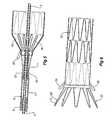
- Figure 6shows a portion of the fully expanded stent graft 13.
- the exposed stent 11has expanded such that the barbs 27 which were within the capsule 7 and hence not able to prematurely engage the vasculature of a patient have now been released and can engage the vasculature to hold the stent graft in the selected place.
- the retention loops 25are still engaged with the stent graft 13 and these remain with the stent graft. Being on the outside of the stent graft, however, they do not interfere with flow of blood through the stent graft.
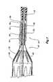
- This embodiment of the inventionhas been depicted in respect to a distally extending exposed stent on the stent graft and a capsule catheter with a proximal facing opening to the capsule on the capsule catheter. It will be realised, however, that in another embodiment the capsule may be distally opening and associated with the nose cone dilator and a proximally extending exposed stent on the stent graft. Such an arrangement is shown in Figure 7 .
- FIG. 7shows cross sectional detail of a proximal region of a deployment device.
- the deployment device 40has a guide wire catheter 42 with a nose cone dilator 44 at its proximal end. At the distal end of the nose cone dilator 44 is a distally opening capsule 46. The proximal end 47 stent graft 48 is restrained by its proximally extending exposed stent 50 being received in the capsule 46.
- a trigger release wire 52extends from a release mechanism (not shown) through the stent graft 48 and out of the capsule through an aperture 54 in the capsule and back in again through another aperture 56 where it passes through one of the loops 59 of the proximally extending exposed stent 50 before terminating within the nose cone dilator 44.
- a retention loop 58is engaged with the material of the stent graft 48 and around the trigger release wire 52 where it exits from the capsule 46 at aperture 54.
- the retention loop 58is preferably formed from a length of suture material. This retention loop 58 prevents the stent graft 48 from either moving longitudinally or undesirably rotating with respectto the capsule 46 until the trigger release wire 52 is removed.
Landscapes
- Health & Medical Sciences (AREA)
- Engineering & Computer Science (AREA)
- Biomedical Technology (AREA)
- Cardiology (AREA)
- Oral & Maxillofacial Surgery (AREA)
- Transplantation (AREA)
- Heart & Thoracic Surgery (AREA)
- Vascular Medicine (AREA)
- Life Sciences & Earth Sciences (AREA)
- Animal Behavior & Ethology (AREA)
- General Health & Medical Sciences (AREA)
- Public Health (AREA)
- Veterinary Medicine (AREA)
- Gastroenterology & Hepatology (AREA)
- Pulmonology (AREA)
- Prostheses (AREA)
- Surgical Instruments (AREA)
Abstract
Description
- This invention relates to a medical device and more particularly a medical device for the deployment of a stent graft into the human or animal body.
- A stent graft can be deployed into the vasculature of a patient to repair a defect in the vasculature such as an aortic dissection or an abdominal or thoracic aortic aneurism.
- Some stent grafts for the treatment of aortic dissections or an abdominal or thoracic aortic aneurysms include an exposed stent extending distally or proximally from the stent graft. Such a stent graft can include one of more barbs to assist with retention of the exposed stent into the vasculature of a patient and hence to prevent inadvertent or early engagement of the barbs with the vasculature when deploying the stent graft and introduction device for the stent graft may include a capsule which encompasses the exposed stent and the barbs. To release the exposed stent the capsule is moved relative to the stent graft and exposed stent.
- It is desirable, however, that premature release does not occur and hence it has been proposed to use a release wire which passes through an aperture in the capsule and engages part of the exposed stent within the capsule.
- This arrangement does not prevent relative rotation of the stent graft with respect to the introduction device and capsule nor can it entirely prevent premature release. Rotation of the exposed stent within the capsule can also cause entanglement of the struts of the exposed stent which can cause problems on deployment.
US-A-20030014103 discloses an artificial blood vessel comprising a cover and wire rings, with an end ring having loop-shaped hooking means which can be engaged by strings. The artificial blood vessel is deployed from a catheter with the loops still engaged with the strings.WO-A-9853761 US 2001/0037142 discloses a stent graft assembly in which a trigger wire extends from a pusher body into a small aperture of a capsule through a loop at the joined proximal ends of struts of an exposed stent and then into a dilator. To deploy the stent, withdrawal of the trigger wire releases the stent struts, and pushing the stent releases the stent struts to self-expand.- The object of this invention is to provide a safety release mechanism such as a stent graft retention system to at least prevent premature release of the stent graft and particularly the exposed stent from the capsule. It is a further object to prevent undesirable rotation of the stent graft with respect to its retention mechanism.
- Throughout this specification the term dista I with respect to a portion of the aorta, a deployment device or a stent graft or prosthesis is the end of the aorta, deployment device or stent graft further away in the direction of blood flow away from the heart and the term proximal means the portion of the aorta, deployment device or end of the stent graft nearer to the heart. When applied to other vessels similar terms such as caudal and cranial should be understood.
- A retention system according to the present invention is defined in claim 1.
- Embodiments of the invention include a retention system for retaining a stent graft onto a deployment device, the stent graft being of a type having an exposed stent at at least one end thereof and the deployment device including a capsule to receive the exposed stent during deployment and an arrangement to move the capsule with respect to the exposed stent to release the exposed stent when required. The retention system further includes a release wire associated with the deployment device to engage a portion of the exposed stent within the capsule and hence retain the exposed stent in the capsule and at least one retention loop on the stent graft, the release wire passing through the retention loop to prevent removal of the capsule from the exposed stent until the release wire has been removed from its engagement with the exposed stent within the capsule and with the at least one retention loop.
- Preferably the release wire passesthrough an aperture in the capsule and the at least one retention loop is engaged to the release wire where it passes through the aperture in the capsule.
- There may be provided two retention loops which are positioned on diametrically opposed sides of the stent graft whereby to also prevent relative rotation between the stent graft and deployment device as well as to prevent premature release.
- In one embodiment the exposed stent on the stent graft may be a distally extending exposed stent. In an alternative embodiment the exposed stent may be a proximally extending exposed stent.
- The at least one retention loop preferably remains with the stent graft after deployment.
- It will be noted that by this arrangement the retention loop acts to prevent the stent graft from being prematurely pulled out of the capsule.
- In the case of a stent graft suitable for treatment of a thoracic aortic aneurism the exposed stent may be a distally extending exposed stent and in the case of a stent graft suitable for treatment of an abdominal aortic aneurism the exposed stent may be a proximally extending exposed stent.
- Embodiments of the invention include a stent graft deployment device including a stent graft retained thereon, the stent graft deployment device comprising a deployment catheter, a proximally opening capsule at the proximal end of the deployment catheter with an exposed stent of the stent graft being received in the capsule, and a trigger wi re release mechanism including a trigger wire engaging the exposed stent of the stent graft in the capsule, a retention arrangement extending from the stent graft to engage the trigger wire at the ca psule, wherein the exposed stent of the stent graft ca nnot be removed from the capsule until the trigger wire has been removed and the retention arrangement released.
- In one embodiment the retention arrangement extending from the stent graft to the trigger wire at the capsule comprises at least one loop of a suture material. Alternatively it comprises two loops of a suture material with the loops engaging the stent graft at diametrically opposed sides of the stent graft.
- Embodiments of the invention include a stent graft deployment device including a stent graft retained thereon, the stent graft deployment device comprising a deployment catheter extending to a nose cone dilator at its proximal end, a distally opening capsule at the distal end of the nose cone dilator with a proximally extending exposed stent of the stent graft being received in the capsule, and a trigger wire release mechanism including a trigger wire engaging the exposed stent of the stent graft in the capsule, a retention arrangement extending from the stent graft to engage the trigger wire at the capsule, wherein the exposed stent of the stent graft cannot be removed from the capsule until the trigger wire has been removed and the retention arrangement released.
- In one embodiment the retention arrangement extending from the stent graft to the trigger wire at the capsule comprises at least one loop of a suture material. Alternatively it comprises two loops of a suture material with the loops engaging the stent graft at diametrically opposed sides of the stent graft.
- The graft material from which the covering of the stent graft of the present invention may be formed may be a commercially available synthetic material such as Dacron, expanded polytetrafluoroethylene (ePTFE), Thoralon™ material, or other synthetic biocompatible materials. Alternatively a naturally occurring biomaterial, such as collagen, is highly desirable, particularly a specially derived collagen material known as a collagenous extracellular matrix (ECM) material, such as small intestinal submucosa (SIS). Besides SIS, examples of ECM's include pericardium, stomach submucosa, liver basement membrane, urinary bladder submucosa, tissue mucosa, and dura mater.
- SIS is particularly useful, and can be made in the fashion described in
Badylak et al., US Patent 4,902,508 ; Intestinal Collagen Layerdescribed inUS Patent 5,733,337 to Carr and in17 Nature Biotechnology 1083 (Nov. 1999); Cook et al., WIPO PublicationWO 98/22158 PCT/US97/14855 US Patents 5,968,096 ;5,955,110 ;5,885,619 ; and5,711,969 . Animal data show that the SIS used in venous valves can be replaced by native tissue in as little as a month's time. In addition to xenogenic biomaterials, such as SIS, autologous tissue can be harvested as well. Additionally Elastin or Elastin-Like Polypetides (ELPs) and the like offer potential as a material to fabricate the covering or frame to form a device with exceptional biocompatibility. Another alternative would be to use allographs such as harvested native valve tissue. Such tissue is commerci ally available in a cryopreserved state. US Patent No. 5,387,235 entitled "Endovascular Transluminal Prosthesis For Repair Of Aneurysms" discloses apparatus and methods of retaining grafts onto deployment devices. These features and other features disclosed inUS Patent No. 5,387,235 could be used with the present invention.U.S. Patent No. 5,720,776 entitled "Barb and Expandable Transluminal Graft Prosthesis For Repair of Aneurysm" discloses improved barbs with various forms of mechanical attachment to a stent. These features and other features disclosed inU.S. Patent No. 5,720,776 could be used with the present invention.US Patent No. 6,206,931 entitled "Graft Prosthesis Materials" discloses graft prosthesis materials and a method for implanting, transplanting, replacing and repairing a part of a patient and particularly the manufacture and use of a purified, collagen based matrix structure removed from a submucosa tissue source. These features and otherfeatures disclosed inUS Patent No. 6,206,931 could be used with the present invention.PCT Patent Publication No. WO 98/53761 PCT Patent Publication No. WO 98/53761 PCT Patent Publication No. WO99/29262 PCT Patent Publication No. WO99/29262 PCT Patent Publication No. WO03/03494 PCT Patent Publication No. WO03/034948 - U.S. Patent Application Publication No.
US-2003-0233140-A1 entitled "Trigger Wires" discloses release wires systems for the release of stent grafts retained on introducer devices. This featu re and other features disclosed in U.S. Patent Application Publication No.US-2003-0233140-A1 could be used with the present invention. - US Patent Application Publication No.
US-2004-0098079-A1 entitled "Thoracic Deployment Device" discloses introducer devices adapted for deployment of stent grafts particularly in the thoracic arch: This feature and other features disclosed in US Patent Application Publication No.US-2004-0098079-A1 could be used with the present invention. - U.S. Patent Application Publication No.
US-2004-0054396-A1 entitled "Stent-Graft Fastening" discloses arrangements for fastening stents onto grafts particularly for exposed stents. This feature and other features disclosed in U.S. Patent Application Publication No.US-2004-0054396-A1 could be used with the present invention. - U.S. Patent Application Publication No.
US-2004-0073289-A1 entitled "Asymmetric Stent Graft Attachment" discloses retention arrangements for retaining onto and releasing prostheses from introducer devices. This feature and other features disclosed in U.S. Patent Application Publication No.US-2004-0073289-A1 could be used with the present invention. PCT Patent Publication No. WO03/053287 PCT Patent Publication No. WO03/05328 - U.S. Patent Application Publication No.
US-2004-0082990-A1 entitled "Composite Prostheses" discloses prostheses or stent grafts suitable for endoluminal deployment. These prostheses and other features disclosed in U.S. Patent Application Publication No.US-2004-0082990-A1 , could be used with the present invention - This then generally describes the invention but to assist with understanding, reference will now be made to the accompanying drawings which show a preferred embodiment of the invention.
In the drawings: Figure 1 shows a stent graft deployment device incorporating one embodiment of the present invention;Figure 2 shows a portion of a deployment device and stent graft at one stage during the deployment process;Figure 3 shows a cross-sectional view of the embodiment shown inFigure 1 ;Figure 4 shows the arrangement ofFigure 2 but with the release wire withdrawn;Figure 5 shows the embodiment ofFigure 3 with the capsule partially retracted;Figure 6 shows a portion of the deployed stent graft and particularly showing the retention loops still on the stent graft; andFigure 7 shows an alternative embodiment of the invention suitable for a proximally extending exposed stent on a stent graft.- Now looking more closely to the drawings and particularly
Figure 1 it will be seen that a deployment device generally shown as 1 includes aguide wire catheter 3 which extends through the deployment device 1. At the proximal end of theguide wire catheter 3 is anose cone dilator 2 and at the distal end is a maleLuer lock connector 6 through which radiographic fluids and the like may be administered. Acapsule catheter 5 which includes a capsule 7 at its proximal end has a longitudinally extendinglumen 15 and thecapsule catheter 5 is coaxially mounted onto theguide wire catheter 3 with theguide wire catheter 3 extending through thelumen 15. Thecapsule catheter 5 extends from adistal handle 34 which in use remains outside a patient to the capsule 7 at its proximal end. Thehandle 34 includes a trigger wire release mechanism generally shown as 32. - Between the
nose cone dilator 2 and the capsule 7 there is a region 8 into which astent graft 13 is retained for deployment. The capsule 7 has a proximally facing internal recess 9 (SeeFigure 3 ) into which is received a distally extending exposedstent 11 of thestent graft 13. Thecapsule catheter 5 can move longitudinally with respect to theguide wire catheter 3 upon release of apin vice 16. Asheath 10 extends from a sheath manipulator 1 2 over thecapsule catheter 5 and in the ready to deploy position extends to thenose cone dilator 2 and retains thestent graft 13 in a compressed state. As shown inFigure 1 , however, thesheath 10 has been withdrawn to distal of the capsule 7 to partially release thestent graft 13. Thestent graft 13 is, however, still retained by the distally extending exposedstent 11 of thestent graft 13 being retained within the capsule 7 and a proximal retention generally shown as 14. Figures 2 to 5 show detail of the capsule region of the deployment device withFigures 3 to 5 being cross sectional views along the line 3 - 3' inFigure 2 .- As depicted in
Figures 2 and 3 the stage of deployment of the stent graft is that at which thesheath 10 which is used to cover thestent graft 13 during introduction, has been retracted to release thestent graft 13 from a restricted condition except where it is still retained by the capsule 7. Thestent graft 13 is retained by the distally extending exposedstent 11 of thestent graft 13 being retained within the capsule 7. - Passing through the
lumen 15 of thecatheter 5 is arelease wire 17 which passes into theinternal recess 9 and within theinternal recess 9 in the capsule 7 therelease wire 17 passes through aloop 19 of the exposedstent 11 and then through anaperture 21 in the capsule 7. Therelease wire 17 then passes through anotheraperture 23 back into the capsuleinternal recess 9 and terminates within thestent graft 13. At least oneretention loop 25 of suture material or similar material is engaged into the material of thestent graft 13 and at its other end is looped around therelease wire 17 where it passes into theaperture 23 in the capsule 7. - In
Figure 2 tworetention loops 25 can be seen and these are placed substantially diametrically opposite to each other where the engage into the material on the distal end of thestent graft 13. By spacing the tworetention loops 25 substantially diametrically opposite to each other on thestent graft 13 undesirable rotation of thestent graft 13 with respect to the capsule catheter may be prevented. In practice thestent graft 13 would be mounted onto the deployment device and therelease wire 17 put in place and then a length of suture material would be stitched into the graft material of the stent graft and passed around therelease wire 17 and then knotted to form theloop 25. - As can be seen in
Figure 4 the release wire has been removed from the introducer device by actuation of the triggerwire release mechanism 32 on the handle 34 (seeFigure 1 ) and hence theloop 25 is no longer retained by the release wire and theloop 19 of the exposedstent 11 is also not retained. - At this stage, therefore, the
capsule catheter 5 can be moved distally with respect to theguide wire catheter 3 so that the situation inFigure 5 occurs. At this stage the exposedstent 11 exits theinternal recess 9 and is partially freed from its engagement within the capsule 7 and the distal end of thestent graft 13 has started to expand under the action of the distal-most self expandingzig zag stent 30. Thebarbs 27 on the exposedstent 11 are now exposed. Figure 6 shows a portion of the fully expandedstent graft 13. The exposedstent 11 has expanded such that thebarbs 27 which were within the capsule 7 and hence not able to prematurely engage the vasculature of a patient have now been released and can engage the vasculature to hold the stent graft in the selected place. It will be noted, too, that theretention loops 25 are still engaged with thestent graft 13 and these remain with the stent graft. Being on the outside of the stent graft, however, they do not interfere with flow of blood through the stent graft.- Generally it will be seen that by this arrangement the exposed stent on the stent graft is prevented from either moving longitudinally or rotating with respect to the capsule in which it is retained by use of the safety retention loops of the present invention.
- This embodiment of the invention has been depicted in respect to a distally extending exposed stent on the stent graft and a capsule catheter with a proximal facing opening to the capsule on the capsule catheter. It will be realised, however, that in another embodiment the capsule may be distally opening and associated with the nose cone dilator and a proximally extending exposed stent on the stent graft. Such an arrangement is shown in
Figure 7 . Figure 7 shows cross sectional detail of a proximal region of a deployment device. Thedeployment device 40 has aguide wire catheter 42 with anose cone dilator 44 at its proximal end. At the distal end of thenose cone dilator 44 is adistally opening capsule 46. Theproximal end 47stent graft 48 is restrained by its proximally extending exposedstent 50 being received in thecapsule 46. Atrigger release wire 52 extends from a release mechanism (not shown) through thestent graft 48 and out of the capsule through anaperture 54 in the capsule and back in again through anotheraperture 56 where it passes through one of theloops 59 of the proximally extending exposedstent 50 before terminating within thenose cone dilator 44. Aretention loop 58 is engaged with the material of thestent graft 48 and around thetrigger release wire 52 where it exits from thecapsule 46 ataperture 54. Theretention loop 58 is preferably formed from a length of suture material. Thisretention loop 58 prevents thestent graft 48 from either moving longitudinally or undesirably rotating with respectto thecapsule 46 until thetrigger release wire 52 is removed.- Throughout this specification various indications have been given as to the scope of this invention but the invention is not limited to any one of these but may reside in two or more of these combined together. The examples are given for illustration only and not for limitation.
- Throughout this specification and the claims that follow unless the context requires otherwise, the words 'comprise' and 'include' and variations such as 'comprising' and 'including' will be understood to imply the inclusion of a stated integer or group of integers but not the exclusion of any other integer or group of integers.
Claims (14)
- A retention system comprising a stent graft (13, 48) and a deployment device (1, 40), the retention system being suitable to retain the stent graft onto the deployment device, the stent graft having an exposed stent (11, 50) extending beyond at least one end of the stent graft material of the stent graft and the deployment device including a capsule (7, 46) to receive within its interior the exposed stent during deployment and an arrangement (5) to move the capsule with respect to the exposed stent to release the exposed stent, the retention system comprising a release wire (17, 52) associated with the deployment device to engage a portion of the exposed stent within the capsule whereby retaining the exposed stent in the capsule andcharacterised in that the release wire further engages a retention arrangement (25, 58) on the stent graft material, the release wire engaging with the retention arrangement to prevent the exposed stent from being released from the interior of the capsule until the release wire has been removed from its engagement with the exposed stent within the capsule and with the retention arrangement.
- A retention system according to Claim 1, wherein the retention arrangement comprises at least one retention loop (25, 58) through which the release wire passes.
- A retention system as in Claim 2 wherein the release wire passes through an aperture (23) in the capsule and the at least one retention loop (25) is engaged to the release wire where it passes through the aperture in the capsule.
- A retention system as in Claim 2 wherein there are two retention loops (25) which are positioned on diametrically opposed sides of the stent graft whereby to also prevent relative rotation between the stent graft and deployment device as well as to prevent premature release.
- A retention system as in Claim 2 wherein the exposed stent is a distally extending exposed stent (11).
- A retention system as in Claim 2 wherein the exposed stent is a proximally extending exposed stent (50).
- A retention system as in Claim 2 wherein at least one retention loop (25, 58) remains within the stent graft (13, 48) after deployment.
- A retention system as in Claim 2 wherein graft material from which a covering of the stent graft (13, 48) is formed is selected from the group comprising a biocompatible synthetic material, Thoralon™ material expanded ploytetrafluoroethylene (ePTFE), a naturally occurring biomaterial or collagenous extracellular matrix (ECM) material.
- A stent graft deployment device (1) including a retention system according to any preceding claim with the stent graft (13) retained thereon, the stent graft deployment device comprising a deployment catheter (5), a proximally opening capsule (7) at the proximal end of the deployment catheter, and a trigger wire release -mechanism including the release wire (17) engaging the exposed stent (11) of the stent graft in the capsule.
- A stent graft deployment device as in Claim 9 wherein the retention arrangement comprises at least one loop (25) of a suture material.
- A stent graft deployment device as in claim 9 wherein the retention arrangement comprises two loops (25) of a suture material with the loops engaging the stent graft at diametrically-opposed sides of the stent graft (13).
- A stent graft deployment device including a retention system according to any of claims 1 to 8 with the stent graft (48) retained thereon, the stent graft deployment device comprising a deployment catheter extending to a nose cone dilator (2) at its proximal end, a distally opening capsule (46) at the distal end of the nose cone dilator with a proximally extending exposed stent (50) of the stent graft being received in the capsule, and a trigger wire release mechanism including the release wire (52) engaging the exposed stent of the stent graft in the capsule.
- A stent graft deployment device as in Claim 12 where the retention arrangement comprises at least one loop (58) of a suture material.
- A stent graft deployment device as in Claim 12 wherein the retention arrangement comprises two loops of a suture material with the loops engaging the stent graft at diametrically opposed sides of the stent graft.
Applications Claiming Priority (2)
| Application Number | Priority Date | Filing Date | Title |
|---|---|---|---|
| US51022803P | 2003-10-10 | 2003-10-10 | |
| PCT/US2004/033572WO2005034811A1 (en) | 2003-10-10 | 2004-10-12 | Stent graft retention system |
Publications (2)
| Publication Number | Publication Date |
|---|---|
| EP1691720A1 EP1691720A1 (en) | 2006-08-23 |
| EP1691720B1true EP1691720B1 (en) | 2011-06-08 |
Family
ID=34435074
Family Applications (1)
| Application Number | Title | Priority Date | Filing Date |
|---|---|---|---|
| EP04794824AExpired - LifetimeEP1691720B1 (en) | 2003-10-10 | 2004-10-12 | Stent graft retention system |
Country Status (6)
| Country | Link |
|---|---|
| US (1) | US7335224B2 (en) |
| EP (1) | EP1691720B1 (en) |
| JP (1) | JP4850712B2 (en) |
| AU (1) | AU2004279461B2 (en) |
| CA (1) | CA2541807C (en) |
| WO (1) | WO2005034811A1 (en) |
Cited By (1)
| Publication number | Priority date | Publication date | Assignee | Title |
|---|---|---|---|---|
| US9238090B1 (en) | 2014-12-24 | 2016-01-19 | Fettech, Llc | Tissue-based compositions |
Families Citing this family (96)
| Publication number | Priority date | Publication date | Assignee | Title |
|---|---|---|---|---|
| US20100318174A1 (en)* | 1998-12-11 | 2010-12-16 | Endologix, Inc. | Implantable vascular graft |
| WO2002039888A2 (en)* | 2000-11-15 | 2002-05-23 | Endologix, Inc. | Implantable vascular graft |
| US8038708B2 (en)* | 2001-02-05 | 2011-10-18 | Cook Medical Technologies Llc | Implantable device with remodelable material and covering material |
| US20070027535A1 (en)* | 2005-07-28 | 2007-02-01 | Cook Incorporated | Implantable thromboresistant valve |
| WO2004049982A2 (en) | 2002-12-02 | 2004-06-17 | Gi Dynamics, Inc. | Bariatric sleeve |
| US7025791B2 (en) | 2002-12-02 | 2006-04-11 | Gi Dynamics, Inc. | Bariatric sleeve |
| US7608114B2 (en) | 2002-12-02 | 2009-10-27 | Gi Dynamics, Inc. | Bariatric sleeve |
| US11259945B2 (en) | 2003-09-03 | 2022-03-01 | Bolton Medical, Inc. | Dual capture device for stent graft delivery system and method for capturing a stent graft |
| US11596537B2 (en) | 2003-09-03 | 2023-03-07 | Bolton Medical, Inc. | Delivery system and method for self-centering a proximal end of a stent graft |
| US8500792B2 (en) | 2003-09-03 | 2013-08-06 | Bolton Medical, Inc. | Dual capture device for stent graft delivery system and method for capturing a stent graft |
| US8292943B2 (en) | 2003-09-03 | 2012-10-23 | Bolton Medical, Inc. | Stent graft with longitudinal support member |
| US20080264102A1 (en) | 2004-02-23 | 2008-10-30 | Bolton Medical, Inc. | Sheath Capture Device for Stent Graft Delivery System and Method for Operating Same |
| US20070198078A1 (en) | 2003-09-03 | 2007-08-23 | Bolton Medical, Inc. | Delivery system and method for self-centering a Proximal end of a stent graft |
| US7763063B2 (en) | 2003-09-03 | 2010-07-27 | Bolton Medical, Inc. | Self-aligning stent graft delivery system, kit, and method |
| US9198786B2 (en) | 2003-09-03 | 2015-12-01 | Bolton Medical, Inc. | Lumen repair device with capture structure |
| US7666219B2 (en)* | 2003-10-15 | 2010-02-23 | Cook Incorporated | Prosthesis deployment system retention device |
| AU2004305450B2 (en) | 2003-12-09 | 2009-01-08 | Gi Dynamics, Inc. | Intestinal sleeve |
| DE602005024585D1 (en) | 2004-09-28 | 2010-12-16 | Cook William Europ | DEVICE FOR TREATING AORTIAL DISEASE |
| CN1911188B (en)* | 2005-08-09 | 2010-10-13 | 微创医疗器械(上海)有限公司 | Stent prosthesis used for surgical operation, and delivery device therefor |
| JP5181211B2 (en)* | 2005-12-23 | 2013-04-10 | クック・メディカル・テクノロジーズ・リミテッド・ライアビリティ・カンパニー | Trigger wire release mechanism and introducer for prosthesis including the same |
| US8808346B2 (en)* | 2006-01-13 | 2014-08-19 | C. R. Bard, Inc. | Stent delivery system |
| US9375215B2 (en)* | 2006-01-20 | 2016-06-28 | W. L. Gore & Associates, Inc. | Device for rapid repair of body conduits |
| US9308105B2 (en)* | 2006-04-19 | 2016-04-12 | Cook Medical Technologies Llc | Delivery device for an endoluminal prosthesis |
| ES2382364T3 (en)* | 2006-09-28 | 2012-06-07 | St George Medical Inc | Thoracic aortic aneurysm repair device. |
| US8052732B2 (en)* | 2006-11-14 | 2011-11-08 | Medtronic Vascular, Inc. | Delivery system for stent-graft with anchoring pins |
| US9149379B2 (en)* | 2007-07-16 | 2015-10-06 | Cook Medical Technologies Llc | Delivery device |
| US8092510B2 (en)* | 2007-07-25 | 2012-01-10 | Cook Medical Technologies Llc | Retention wire for self-expanding stent |
| US10813779B2 (en)* | 2008-04-25 | 2020-10-27 | CARDINAL HEALTH SWITZERLAND 515 GmbH | Stent attachment and deployment mechanism |
| WO2009148607A1 (en)* | 2008-06-04 | 2009-12-10 | Gore Enterprise Holdings, Inc. | Controlled deployable medical device and method of making the same |
| CA2727000C (en) | 2008-06-04 | 2014-01-07 | Gore Enterprise Holdings, Inc. | Controlled deployable medical device and method of making the same |
| CN102076281B (en) | 2008-06-30 | 2014-11-05 | 波顿医疗公司 | Systems and methods for abdominal aortic aneurysm |
| US11376114B2 (en) | 2008-10-31 | 2022-07-05 | Cook Medical Technologies Llc | Introducer for deploying a stent graft in a curved lumen and stent graft therefor |
| GB2464977B (en) | 2008-10-31 | 2010-11-03 | William Cook Europe As | Introducer for deploying a stent graft in a curved lumen and stent graft therefor |
| EP2391309B1 (en)* | 2008-12-30 | 2018-04-04 | Cook Medical Technologies LLC | Delivery device |
| EP3284447B1 (en) | 2009-03-13 | 2020-05-20 | Bolton Medical Inc. | System for deploying an endoluminal prosthesis at a surgical site |
| US8771333B2 (en)* | 2009-06-23 | 2014-07-08 | Cordis Corporation | Stent-graft securement device |
| WO2011059707A1 (en)* | 2009-10-29 | 2011-05-19 | William A. Cook Australia Pty. Ltd. | Stent delivery system with nitinol trigger wire |
| JP5901538B2 (en)* | 2010-01-29 | 2016-04-13 | クック・メディカル・テクノロジーズ・リミテッド・ライアビリティ・カンパニーCook Medical Technologies Llc | Stent feeding device |
| US8926693B2 (en)* | 2010-02-17 | 2015-01-06 | Medtronic, Inc. | Heart valve delivery catheter with safety button |
| US9101455B2 (en) | 2010-08-13 | 2015-08-11 | Cook Medical Technologies Llc | Preloaded wire for endoluminal device |
| CA2747610C (en) | 2010-08-13 | 2014-09-16 | Cook Medical Technologies Llc | Precannulated fenestration |
| US9095466B2 (en) | 2010-11-16 | 2015-08-04 | W. L. Gore & Associates, Inc. | Apposition fiber for use in endoluminal deployment of expandable devices in tortuous anatomies |
| US9775982B2 (en) | 2010-12-29 | 2017-10-03 | Medtronic, Inc. | Implantable medical device fixation |
| US10112045B2 (en) | 2010-12-29 | 2018-10-30 | Medtronic, Inc. | Implantable medical device fixation |
| US9198787B2 (en) | 2010-12-31 | 2015-12-01 | Cook Medical Technologies Llc | Conformable prosthesis delivery system and method for deployment thereof |
| US9028540B2 (en)* | 2011-03-25 | 2015-05-12 | Covidien Lp | Vascular stent with improved vessel wall apposition |
| EP2535025A1 (en)* | 2011-06-17 | 2012-12-19 | Cook Medical Technologies LLC | Trigger wire release mechanism |
| EP2604232B1 (en) | 2011-12-14 | 2021-02-24 | Cook Medical Technologies LLC | Circumferential trigger wire for deploying an endoluminal prosthesis |
| EP2985007B1 (en) | 2011-12-22 | 2019-11-13 | Cook Medical Technologies LLC | Preloaded wire for endoluminal device |
| US9220906B2 (en)* | 2012-03-26 | 2015-12-29 | Medtronic, Inc. | Tethered implantable medical device deployment |
| US9833625B2 (en) | 2012-03-26 | 2017-12-05 | Medtronic, Inc. | Implantable medical device delivery with inner and outer sheaths |
| US9717421B2 (en) | 2012-03-26 | 2017-08-01 | Medtronic, Inc. | Implantable medical device delivery catheter with tether |
| US9339197B2 (en) | 2012-03-26 | 2016-05-17 | Medtronic, Inc. | Intravascular implantable medical device introduction |
| US10485435B2 (en) | 2012-03-26 | 2019-11-26 | Medtronic, Inc. | Pass-through implantable medical device delivery catheter with removeable distal tip |
| US9854982B2 (en) | 2012-03-26 | 2018-01-02 | Medtronic, Inc. | Implantable medical device deployment within a vessel |
| EP2846743B1 (en) | 2012-04-12 | 2016-12-14 | Bolton Medical Inc. | Vascular prosthetic delivery device |
| US9173756B2 (en) | 2012-06-13 | 2015-11-03 | Cook Medical Technologies Llc | Systems and methods for deploying a portion of a stent using at least one coiled member |
| US9144510B2 (en) | 2012-06-13 | 2015-09-29 | Cook Medical Technologies Llc | Systems and methods for deploying a portion of a stent using at least one coiled member |
| US9254205B2 (en) | 2012-09-27 | 2016-02-09 | Covidien Lp | Vascular stent with improved vessel wall apposition |
| EP2745813A1 (en) | 2012-12-18 | 2014-06-25 | Cook Medical Technologies LLC | Preloaded wire for endoluminal device |
| US9622893B2 (en) | 2012-12-20 | 2017-04-18 | Cook Medical Technologies Llc | Apparatus and method for improved deployment of endovascular grafts |
| US9687373B2 (en) | 2012-12-21 | 2017-06-27 | Cook Medical Technologies Llc | Systems and methods for securing and releasing a portion of a stent |
| US9655756B2 (en) | 2012-12-21 | 2017-05-23 | Cook Medical Technologies Llc | Systems and methods for deploying a portion of a stent using an auger-style device |
| US9308108B2 (en) | 2013-03-13 | 2016-04-12 | Cook Medical Technologies Llc | Controlled release and recapture stent-deployment device |
| US9439751B2 (en) | 2013-03-15 | 2016-09-13 | Bolton Medical, Inc. | Hemostasis valve and delivery systems |
| BR102013023069A2 (en)* | 2013-09-10 | 2015-08-11 | Abdo Farret Neto | Self-expanding ostial stent and method of application |
| CN106175985B (en)* | 2015-04-29 | 2018-08-24 | 上海微创心通医疗科技有限公司 | Drive handle for delivering an implant and delivery system |
| US10610393B2 (en) | 2016-03-24 | 2020-04-07 | Cook Medical Technologies Llc | Wire retention and release mechanisms |
| US10772751B2 (en) | 2016-09-09 | 2020-09-15 | Cook Medical Technologies Llc | Fenestrated endoluminal prosthesis and system and method of deployment thereof |
| US10603198B2 (en) | 2016-09-09 | 2020-03-31 | Cook Medical Technologies Llc | Prosthesis deployment system and method |
| CN115054413A (en) | 2016-09-29 | 2022-09-16 | 美国医疗设备有限公司 | Method of adjusting effective length of stent and prosthesis delivery catheter assembly |
| US11246727B2 (en) | 2016-10-31 | 2022-02-15 | Cook Medical Technologies Llc | Suture esophageal stent introducer |
| US10500080B2 (en)* | 2016-10-31 | 2019-12-10 | Cook Medical Technologies Llc | Suture esophageal stent introducer |
| US10849775B2 (en) | 2016-10-31 | 2020-12-01 | Cook Medical Technologies Llc | Suture esophageal stent introducer parallel handle |
| US10765545B2 (en) | 2016-10-31 | 2020-09-08 | Cook Medical Technologies Llc | Suture esophageal stent introducer |
| US10702408B2 (en) | 2016-10-31 | 2020-07-07 | Cook Medical Technologies Llc | Suture esophageal stent introducer |
| US11413175B2 (en) | 2016-10-31 | 2022-08-16 | Cook Medical Technologies Llc | Tube and suture stent introducer system |
| US11141299B2 (en) | 2016-10-31 | 2021-10-12 | Cook Medical Technologies Llc | Suture esophageal stent introducer |
| US11141298B2 (en) | 2016-10-31 | 2021-10-12 | Cook Medical Technologies Llc | Suture esophageal stent introducer |
| US10463517B2 (en)* | 2017-01-16 | 2019-11-05 | Cook Medical Technologies Llc | Controlled expansion stent graft delivery system |
| US10646324B2 (en) | 2017-01-31 | 2020-05-12 | Cook Medical Technologies, LLC | Bifurcated stent graft with hemodynamic blood flow dividing wall |
| EP4467111A3 (en) | 2017-03-15 | 2025-03-05 | Merit Medical Systems, Inc. | Transluminal stents |
| ES2982356T3 (en)* | 2017-04-21 | 2024-10-15 | Merit Medical Systems Inc | Deployable endoprostheses and devices, and related systems |
| US10709541B2 (en) | 2017-04-28 | 2020-07-14 | Cook Medical Technologies Llc | Systems and methods for adjusting the diameter of an endoluminal prosthesis and an endoluminal prosthesis configured for the same |
| US10441221B2 (en) | 2017-06-26 | 2019-10-15 | Cook Medical Technologies Llc | Graft prosthesis with pocket for microsystem |
| WO2019122944A1 (en) | 2017-12-19 | 2019-06-27 | Kardiozis Sas | Delivery device, delivery system, stent graft and a support structure |
| US10874850B2 (en) | 2018-09-28 | 2020-12-29 | Medtronic, Inc. | Impedance-based verification for delivery of implantable medical devices |
| US12151100B2 (en) | 2019-05-07 | 2024-11-26 | Medtronic, Inc. | Tether assemblies for medical device delivery systems |
| US11331475B2 (en) | 2019-05-07 | 2022-05-17 | Medtronic, Inc. | Tether assemblies for medical device delivery systems |
| CA3171343A1 (en)* | 2020-02-20 | 2021-08-26 | Major Medical Devices Inc | Systems and methods for introducing a stent-graft through a blood vessel located above a diaphragm |
| EP4585192A3 (en) | 2020-06-24 | 2025-10-15 | Bolton Medical, Inc. | Anti-backspin component for vascular prosthesis delivery device |
| EP4185239A4 (en) | 2020-07-24 | 2024-08-07 | Merit Medical Systems, Inc. | ESOPHAGEAL STENT PROSTHESES AND RELATED METHODS |
| CA3194910A1 (en) | 2020-10-26 | 2022-05-05 | Tiffany ETHRIDGE | Esophageal stents with helical thread |
| GB2605559B (en) | 2021-01-07 | 2023-04-05 | Cook Medical Technologies Llc | Stent graft |
| US20240225868A9 (en)* | 2021-02-22 | 2024-07-11 | W. L. Gore & Associates, Inc. | Multi-component delivery systems and methods |
| US20250032284A1 (en)* | 2023-07-25 | 2025-01-30 | Mavericks Endo, Inc. | Delivery systems for aortic arch repair devices, and associated devices and methods |
Citations (3)
| Publication number | Priority date | Publication date | Assignee | Title |
|---|---|---|---|---|
| US20010037142A1 (en)* | 2000-03-14 | 2001-11-01 | Cook Incorporated | Endovascular stent graft |
| US20040138734A1 (en)* | 2001-04-11 | 2004-07-15 | Trivascular, Inc. | Delivery system and method for bifurcated graft |
| EP1440673A1 (en)* | 2003-01-24 | 2004-07-28 | Medtronic Vascular, Inc. | Stent-graft delivery system |
Family Cites Families (6)
| Publication number | Priority date | Publication date | Assignee | Title |
|---|---|---|---|---|
| US5693083A (en)* | 1983-12-09 | 1997-12-02 | Endovascular Technologies, Inc. | Thoracic graft and delivery catheter |
| WO1996036297A1 (en)* | 1995-05-19 | 1996-11-21 | Kanji Inoue | Transplantation instrument, method of bending same and method of transplanting same |
| US5776142A (en)* | 1996-12-19 | 1998-07-07 | Medtronic, Inc. | Controllable stent delivery system and method |
| AUPO700897A0 (en)* | 1997-05-26 | 1997-06-19 | William A Cook Australia Pty Ltd | A method and means of deploying a graft |
| US6328755B1 (en)* | 1998-09-24 | 2001-12-11 | Scimed Life Systems, Inc. | Filter delivery device |
| EP1487380B1 (en)* | 2002-03-25 | 2008-02-27 | Cook Incorporated | Branched vessel prothesis |
- 2004
- 2004-10-12EPEP04794824Apatent/EP1691720B1/ennot_activeExpired - Lifetime
- 2004-10-12JPJP2006534460Apatent/JP4850712B2/ennot_activeExpired - Lifetime
- 2004-10-12AUAU2004279461Apatent/AU2004279461B2/ennot_activeExpired
- 2004-10-12USUS10/962,764patent/US7335224B2/ennot_activeExpired - Lifetime
- 2004-10-12CACA2541807Apatent/CA2541807C/ennot_activeExpired - Lifetime
- 2004-10-12WOPCT/US2004/033572patent/WO2005034811A1/enactiveApplication Filing
Patent Citations (3)
| Publication number | Priority date | Publication date | Assignee | Title |
|---|---|---|---|---|
| US20010037142A1 (en)* | 2000-03-14 | 2001-11-01 | Cook Incorporated | Endovascular stent graft |
| US20040138734A1 (en)* | 2001-04-11 | 2004-07-15 | Trivascular, Inc. | Delivery system and method for bifurcated graft |
| EP1440673A1 (en)* | 2003-01-24 | 2004-07-28 | Medtronic Vascular, Inc. | Stent-graft delivery system |
Cited By (2)
| Publication number | Priority date | Publication date | Assignee | Title |
|---|---|---|---|---|
| US9238090B1 (en) | 2014-12-24 | 2016-01-19 | Fettech, Llc | Tissue-based compositions |
| US11938246B2 (en) | 2014-12-24 | 2024-03-26 | Fettech, Llc | Tissue-based compositions and methods of use thereof |
Also Published As
| Publication number | Publication date |
|---|---|
| CA2541807C (en) | 2012-07-10 |
| US7335224B2 (en) | 2008-02-26 |
| CA2541807A1 (en) | 2005-04-21 |
| AU2004279461A1 (en) | 2005-04-21 |
| EP1691720A1 (en) | 2006-08-23 |
| US20050107862A1 (en) | 2005-05-19 |
| WO2005034811A1 (en) | 2005-04-21 |
| JP2007508069A (en) | 2007-04-05 |
| AU2004279461B2 (en) | 2010-06-03 |
| JP4850712B2 (en) | 2012-01-11 |
Similar Documents
| Publication | Publication Date | Title |
|---|---|---|
| EP1691720B1 (en) | Stent graft retention system | |
| EP2491892B1 (en) | Stent graft with valve arrangement and introducer assembly therefor | |
| AU2003293269B2 (en) | Method and device for treating aortic dissection | |
| EP1791498B1 (en) | Stent graft with integral side arm | |
| EP2007313B1 (en) | Stent graft | |
| EP2470114B1 (en) | Curve forming stent graft | |
| US8864813B2 (en) | Balloon/self-expanding stent graft | |
| US20060004433A1 (en) | Thoracic deployment device and stent graft | |
| EP2702960B1 (en) | Endoluminal prosthesis and delivery device |
Legal Events
| Date | Code | Title | Description |
|---|---|---|---|
| PUAI | Public reference made under article 153(3) epc to a published international application that has entered the european phase | Free format text:ORIGINAL CODE: 0009012 | |
| 17P | Request for examination filed | Effective date:20060410 | |
| AK | Designated contracting states | Kind code of ref document:A1 Designated state(s):DE DK GB IE IT NL | |
| DAX | Request for extension of the european patent (deleted) | ||
| RBV | Designated contracting states (corrected) | Designated state(s):DE DK GB IE IT NL | |
| 17Q | First examination report despatched | Effective date:20080505 | |
| GRAP | Despatch of communication of intention to grant a patent | Free format text:ORIGINAL CODE: EPIDOSNIGR1 | |
| RIC1 | Information provided on ipc code assigned before grant | Ipc:A61F 2/06 20060101ALI20100129BHEP Ipc:A61F 2/84 20060101AFI20100129BHEP | |
| GRAS | Grant fee paid | Free format text:ORIGINAL CODE: EPIDOSNIGR3 | |
| GRAA | (expected) grant | Free format text:ORIGINAL CODE: 0009210 | |
| AK | Designated contracting states | Kind code of ref document:B1 Designated state(s):DE DK GB IE IT NL | |
| REG | Reference to a national code | Ref country code:GB Ref legal event code:FG4D | |
| REG | Reference to a national code | Ref country code:IE Ref legal event code:FG4D | |
| REG | Reference to a national code | Ref country code:DE Ref legal event code:R096 Ref document number:602004033003 Country of ref document:DE Effective date:20110721 | |
| REG | Reference to a national code | Ref country code:NL Ref legal event code:T3 | |
| RAP2 | Party data changed (patent owner data changed or rights of a patent transferred) | Owner name:COOK MEDICAL TECHNOLOGIES LLC | |
| RAP2 | Party data changed (patent owner data changed or rights of a patent transferred) | Owner name:COOK MEDICAL TECHNOLOGIES LLC | |
| PLBE | No opposition filed within time limit | Free format text:ORIGINAL CODE: 0009261 | |
| STAA | Information on the status of an ep patent application or granted ep patent | Free format text:STATUS: NO OPPOSITION FILED WITHIN TIME LIMIT | |
| 26N | No opposition filed | Effective date:20120309 | |
| PG25 | Lapsed in a contracting state [announced via postgrant information from national office to epo] | Ref country code:DK Free format text:LAPSE BECAUSE OF FAILURE TO SUBMIT A TRANSLATION OF THE DESCRIPTION OR TO PAY THE FEE WITHIN THE PRESCRIBED TIME-LIMIT Effective date:20110608 | |
| REG | Reference to a national code | Ref country code:DE Ref legal event code:R097 Ref document number:602004033003 Country of ref document:DE Effective date:20120309 | |
| P01 | Opt-out of the competence of the unified patent court (upc) registered | Effective date:20230602 | |
| PGFP | Annual fee paid to national office [announced via postgrant information from national office to epo] | Ref country code:NL Payment date:20230919 Year of fee payment:20 Ref country code:IE Payment date:20230925 Year of fee payment:20 Ref country code:GB Payment date:20230914 Year of fee payment:20 | |
| PGFP | Annual fee paid to national office [announced via postgrant information from national office to epo] | Ref country code:IT Payment date:20231011 Year of fee payment:20 Ref country code:DE Payment date:20230915 Year of fee payment:20 | |
| REG | Reference to a national code | Ref country code:DE Ref legal event code:R071 Ref document number:602004033003 Country of ref document:DE | |
| REG | Reference to a national code | Ref country code:NL Ref legal event code:MK Effective date:20241011 | |
| REG | Reference to a national code | Ref country code:GB Ref legal event code:PE20 Expiry date:20241011 | |
| REG | Reference to a national code | Ref country code:IE Ref legal event code:MK9A | |
| PG25 | Lapsed in a contracting state [announced via postgrant information from national office to epo] | Ref country code:GB Free format text:LAPSE BECAUSE OF EXPIRATION OF PROTECTION Effective date:20241011 | |
| PG25 | Lapsed in a contracting state [announced via postgrant information from national office to epo] | Ref country code:IE Free format text:LAPSE BECAUSE OF EXPIRATION OF PROTECTION Effective date:20241012 | |
| PG25 | Lapsed in a contracting state [announced via postgrant information from national office to epo] | Ref country code:IE Free format text:LAPSE BECAUSE OF EXPIRATION OF PROTECTION Effective date:20241012 Ref country code:GB Free format text:LAPSE BECAUSE OF EXPIRATION OF PROTECTION Effective date:20241011 |