EP1691277B1 - Context menu providing dependency relationships for objects of different type - Google Patents
Context menu providing dependency relationships for objects of different typeDownload PDFInfo
- Publication number
- EP1691277B1 EP1691277B1EP05100979AEP05100979AEP1691277B1EP 1691277 B1EP1691277 B1EP 1691277B1EP 05100979 AEP05100979 AEP 05100979AEP 05100979 AEP05100979 AEP 05100979AEP 1691277 B1EP1691277 B1EP 1691277B1
- Authority
- EP
- European Patent Office
- Prior art keywords
- relationship
- objects
- types
- relationships
- type
- Prior art date
- Legal status (The legal status is an assumption and is not a legal conclusion. Google has not performed a legal analysis and makes no representation as to the accuracy of the status listed.)
- Expired - Lifetime
Links
Images


Classifications
- G—PHYSICS
- G06—COMPUTING OR CALCULATING; COUNTING
- G06F—ELECTRIC DIGITAL DATA PROCESSING
- G06F16/00—Information retrieval; Database structures therefor; File system structures therefor
- G06F16/10—File systems; File servers
- G06F16/16—File or folder operations, e.g. details of user interfaces specifically adapted to file systems
- G06F16/168—Details of user interfaces specifically adapted to file systems, e.g. browsing and visualisation, 2d or 3d GUIs
- G—PHYSICS
- G06—COMPUTING OR CALCULATING; COUNTING
- G06F—ELECTRIC DIGITAL DATA PROCESSING
- G06F3/00—Input arrangements for transferring data to be processed into a form capable of being handled by the computer; Output arrangements for transferring data from processing unit to output unit, e.g. interface arrangements
- G06F3/01—Input arrangements or combined input and output arrangements for interaction between user and computer
- G06F3/048—Interaction techniques based on graphical user interfaces [GUI]
- G06F3/0481—Interaction techniques based on graphical user interfaces [GUI] based on specific properties of the displayed interaction object or a metaphor-based environment, e.g. interaction with desktop elements like windows or icons, or assisted by a cursor's changing behaviour or appearance
- G06F3/04817—Interaction techniques based on graphical user interfaces [GUI] based on specific properties of the displayed interaction object or a metaphor-based environment, e.g. interaction with desktop elements like windows or icons, or assisted by a cursor's changing behaviour or appearance using icons
- G—PHYSICS
- G06—COMPUTING OR CALCULATING; COUNTING
- G06F—ELECTRIC DIGITAL DATA PROCESSING
- G06F3/00—Input arrangements for transferring data to be processed into a form capable of being handled by the computer; Output arrangements for transferring data from processing unit to output unit, e.g. interface arrangements
- G06F3/01—Input arrangements or combined input and output arrangements for interaction between user and computer
- G06F3/048—Interaction techniques based on graphical user interfaces [GUI]
- G06F3/0481—Interaction techniques based on graphical user interfaces [GUI] based on specific properties of the displayed interaction object or a metaphor-based environment, e.g. interaction with desktop elements like windows or icons, or assisted by a cursor's changing behaviour or appearance
- G06F3/0482—Interaction with lists of selectable items, e.g. menus
- G—PHYSICS
- G06—COMPUTING OR CALCULATING; COUNTING
- G06F—ELECTRIC DIGITAL DATA PROCESSING
- G06F3/00—Input arrangements for transferring data to be processed into a form capable of being handled by the computer; Output arrangements for transferring data from processing unit to output unit, e.g. interface arrangements
- G06F3/01—Input arrangements or combined input and output arrangements for interaction between user and computer
- G06F3/048—Interaction techniques based on graphical user interfaces [GUI]
- G06F3/0481—Interaction techniques based on graphical user interfaces [GUI] based on specific properties of the displayed interaction object or a metaphor-based environment, e.g. interaction with desktop elements like windows or icons, or assisted by a cursor's changing behaviour or appearance
- G06F3/0483—Interaction with page-structured environments, e.g. book metaphor
- G—PHYSICS
- G06—COMPUTING OR CALCULATING; COUNTING
- G06F—ELECTRIC DIGITAL DATA PROCESSING
- G06F3/00—Input arrangements for transferring data to be processed into a form capable of being handled by the computer; Output arrangements for transferring data from processing unit to output unit, e.g. interface arrangements
- G06F3/01—Input arrangements or combined input and output arrangements for interaction between user and computer
- G06F3/048—Interaction techniques based on graphical user interfaces [GUI]
- G06F3/0484—Interaction techniques based on graphical user interfaces [GUI] for the control of specific functions or operations, e.g. selecting or manipulating an object, an image or a displayed text element, setting a parameter value or selecting a range
- G06F3/04842—Selection of displayed objects or displayed text elements
- Y—GENERAL TAGGING OF NEW TECHNOLOGICAL DEVELOPMENTS; GENERAL TAGGING OF CROSS-SECTIONAL TECHNOLOGIES SPANNING OVER SEVERAL SECTIONS OF THE IPC; TECHNICAL SUBJECTS COVERED BY FORMER USPC CROSS-REFERENCE ART COLLECTIONS [XRACs] AND DIGESTS
- Y10—TECHNICAL SUBJECTS COVERED BY FORMER USPC
- Y10S—TECHNICAL SUBJECTS COVERED BY FORMER USPC CROSS-REFERENCE ART COLLECTIONS [XRACs] AND DIGESTS
- Y10S715/00—Data processing: presentation processing of document, operator interface processing, and screen saver display processing
- Y10S715/975—Pop-up dialog box for entry
Definitions
- the present inventionrelates generally to the field of electronic data processing and specifically to provision of user interfaces to a user.
- the computer systemsare able to support complex computer programs.
- the complex computer programsprovide also complex user interfaces to a user of the complex computer programs.
- a complex user interfaceallows for the exchange of different kinds of information between the computer program and the user. Frequently, the exchanged information is dependent from other information and a dependency may not be obvious to the user.
- the complex user interfaceprovides a graphical user interface that displays many different objects.
- the complex user interfacemay provide one or more devices to the user to select an object and to determine a function which is applied to the selected object.
- a deviceis a graphical pointer which is controlled by the user with a handheld pointing device, for example a computer mouse.
- Displayed objects and applicable functionsdepend on the computer program.
- An exampleis an operating system that allows for a selection of displayed files by the computer mouse and a selection of a function from a menu that is applied to the selected file.
- the number of optional activities that the user can execute with the user interface by combining inputsis typically large. In case an activity requires more than one input it is convenient to support the user by providing additional information to him.
- a context menuOne way to support the user executing an activity is provided by a context menu.
- the userselects an object displayed by the user interface and requests the context menu.
- the context menumay have for example entries of functions that can be applied to the selected object.
- the usermay select one of the listed functions and the selected function is executed for the selected object.
- United States Patent, patent number 5664133discloses a method to support the user by providing the context menu.
- the userselects a first displayed computer resource and a second displayed computer resource and may request a context menu.
- the context menuhas selectable entries associated with a transfer of the first computer resource to the second computer resource.
- the selectable entriesmay be operations that can be executed by the computer program based on the relationship of the first computer resource, that is a file, and the second computer resource, that is a folder.
- United States Patent, patent number 5524246discloses a graphic program configuration system that displays optional objects to a user in a window.
- the optional objectsmay be connection types that are selectable by the user in accordance to previously selected objects, that is, a selected outlet object and a selected subprogram.
- the subprogrammay be connected to outlet objects through pointers and that an outlet object may be connected to connection types also through pointers.
- United States Patent, patent number 5903478discloses a method of displaying an architecture visual model in a symbol based table.
- the architecture visual modelhas visual objects each of which is linked to at least a further visual object.
- the visual objectsare arranged as columns or rows of the symbol based table according to object types of the visual objects.
- a visual symbolindicates a relationship between a visual object arranged as a column and a further visual object arranged as a row.
- displayed objectsmay be numerous and the displayed objects have different object types. Furthermore, relationships may also be numerous and the relationships have one or more relationship types. It is convenient to provide a context menu for such computer programs.
- An example for such a computer programis an operating system displaying a first object which is a file of an object type computer resource and a second object which is a file conversion program of an object type computer program.
- a relationshipmay be of a type file transfer and a further relationship may be of a type application.
- An embodiment of the inventionis disclosed according to features of claim 1.
- the embodimentis a method for providing a context menu with relationships that are of one or more relationship types.
- a relationship of the context menuis applicable to relate two objects that have been selected previously from a set of objects.
- the objects of the set of objectshave a plurality of object types.
- the embodimentis fast and memory efficient because the relationships in the context menu are generated by identifying object types and determining relationship types. Frequently, in a computer program a number of object types is smaller than a number of objects and a number of relationship types is smaller than a number of relationships. Accordingly, it requires less data processing to determine the applicable relationships by using types instead of using objects and relationships.
- the context menuhas only entries with applicable relationships. Relationships that are not applicable to the selected objects are not displayed and are not processed by the computer program. Therefore, the amount of data being processed is reduced contributing to a fast and memory efficient execution of a computer program.
- the embodimentmay prevent errors such as creating a relationship that is not applicable to the selected objects. Such an error may happen when for example a first object is selected, then a relationship applicable to the object is selected and then a second object is selected. In case the second object cannot be related by the selected relationship to the first object the system may try to create an invalid relationship. Even if a following check notices an error it is more efficient to prevent such an error as early as possible. An aspect of error prevention therefore also contributes to the fast execution of the computer program.
- the embodimentalso contributes to the fast execution of the computer program by providing selectable context menu entries which the user may not be aware of in a current situation. By providing such knowledge, the embodiment may prevent unnecessary activities of the user.
- a further embodiment of the inventionis disclosed according to features of claim 14.
- the further embodimentis a computer system for providing a context menu with relationships.
- Features of the further embodimentcorrespond to features of the embodiment.
- aspects of the further embodimentcorrespond to aspects of the embodiment.
- Fig. 1shows method steps of a method of the invention.
- Fig. 2illustrates three successive situations displayed to a user by a user interface.
- Fig. 3shows exemplary assignments and negative assignments for determining applicable relationships.
- Fig. 4shows components of a computer system of the invention.
- Fig. 5illustrates an exemplary situation with two selected objects and a context menu an entry for creating a relationship.
- Fig. 6illustrates an exemplary situation with two selected objects and a context menu with entries for maintaining a relationship.
- Fig. 7illustrates an exemplary situation with three selected objects and a context menu with relationships applicable to the selected objects.
- Fig. 8illustrates an exemplary situation with three selected objects and a context menu with multiple relationships applicable to the selected objects.
- Fig. 9illustrates an exemplary situation with two selected objects and a context menu with a reduced number of entries.
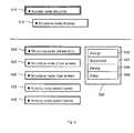
- Fig. 1shows method steps of a method of the invention. Optional method steps of the method are indicated by boxes with dashed lines.
- the methodprovides entries for a context menu.
- the context menuis provided to a user that may select an entry of the context menu.
- the entriesrepresent optional activities with respect to relationships.
- the methoduses available information about a situation of the user to provide the entries. For example, the entries may represent relationships that can be applied to relate previously selected objects, that is, the relationships are applicable to the selected objects. In this way, the method supports the user in an interaction with a computer program.
- the objects and the applicable relationshipsdepend on the computer program.
- An example for the computer programis an operating system that displays files of different types and allows for relating the files.
- the computer programmay display a set of objects that may be related by applicable relationships.
- the display of an objectmay involve the display of an icon representing the object.
- dependenciesthere are dependencies between the objects and between the applicable relationships. According to the dependencies, it may not be possible to use a specific relationship to relate two objects.
- the usermay not be aware of the dependencies and may not know if the specific relationship is applicable to the two objects.
- the usermay request a context menu with the applicable relationships that may be selected from the context menu and are conforming to the dependencies.
- a first method stepis receiving 110 a first identification of a first object which is selected by the user from a set of objects.
- the set of objectsmay be defined by objects that are displayed to the user and selectable by the user.
- the usermay use a graphical pointer device to point to the first object and a button for selecting the first object.
- An example for such a graphical pointer deviceis a computer mouse.
- a request of a context menumay be done by using a further button. The selection of an entry from the context menu may be possible by using again the button which is used for selecting the objects. It depends on the computer program if a selection and the request of the context menu can be done by using the graphical pointer device. Frequently, the computer program supports the graphical pointer device.
- the computer programmay also support selecting a displayed object by pressing repeatedly a first button to navigate an object indicator to the first object and by using a second button to select the first object.
- a user interfacemay register the selection of the first object and the computer program may provide the first identification to the method.
- the first objectwill be marked so that a selection of the first object is visible.
- a following method stepis receiving 120 a second identification of a second object which is selected by the user from the set of objects.
- the selection of the second objectmay be done in an analogous way to the selection the first object.
- An optional method stepis receiving 180 one or more further object identifications from the set of objects.
- a relationship or more than two objects by a relationshipAn example is an operating system which allows for relating a file transformation program with a first file and a second file. Relating the three files may result in transformation of the first file into the format of the second file using the file transformation program. If the computer program allows for relating only two objects it may still be convenient to receive identifications of more than two selected objects because the selected objects can possibly be related by more than one relationship.
- An optional method step checking 190 an object type conditionis related to providing context menu entries for multiple relationships. Multiple relationships require that a condition is fulfilled that an object of the selected objects is of a first object type and residual objects of the selected objects are of a second object type. The multiple relationships may be created between the object of the first object type and each object of the residual objects by creating one relationship multiple times. Creating multiple relationships gives a same result as creating a single relationship separately between the object of the first object type and the each object of the residual objects. Creating the multiple relationships leads to a fast and efficient execution of the computer program.
- a following optional method stepis identifying 160 an existing relationship, that is, a relationship that has been created previously between the selected objects. In case that such a relationship is identified and that no further relationship may be created between the selected objects it may be possible to skip some of the following method steps.
- a following method stepis identifying 130 object types of the selected objects, wherein the object types are from a plurality of object types.
- the file conversion programmay have an object type application program.
- the first file and the second filemay have object type computer resource.
- Other object typesmay be possible which type the objects from the set of objects.
- the determining stepinvolves the identified object types and does not require an identification of a selected object. Accordingly, the determining step is independent of the number of the objects in the set of objects and the number of available relationships. The determining step depends on the number of object types of objects of the set and relationship types. It may be possible to define the object types and the relationship types so that the dependencies between the objects and the applicable relationships can directly be described. As an example, it may be possible to define an object type for file conversion programs that require one file and a further object type for file conversion programs that require two files.
- selecting a file and the file conversion program requiring two filesmay not give an entry in the context menu for applying the file conversion program to the file: a relationship type for applying the file conversion program may not be determined because the object type of the file conversion program requires two file object types.
- the object types and the relationship typesmay be defined by the computer program and may not directly be used to describe the dependencies. In such cases, a following optional step may be conveniently executed.
- the entryrepresents a relationship of the one or more determined relationship types.
- the relationshipis selectable by the user so that it is created between the selected objects.
- Generating step 150may optionally include a step of deleting 210 a relationship.
- the relationshipmay be of the one or more relationship types that have been determined but may have an attribute and the attribute may not fulfill a restriction. No entry for the context menu is generated for a deleted relationship.
- the optional deleting step 210may be useful when object types and relationship types are insufficient to describe the dependencies between the objects and the applicable relationships. In such cases, restrictions applicable to relationship attributes may be used to describe the dependencies in further detail. As an example, it may be possible that a first file conversion program which is applied to one file and a second file conversion program which is applied to two files are of the same relationship type.
- an apply relationship which applies a file conversion programmay be determined even if the second file conversion program and one file have been selected, that is, the apply relationship is not applicable to the selected objects.
- the apply relationshipmay have an attribute specifying the number of the files to which the file conversion program is applied.
- the attributemay have the value one because only one file has been selected.
- a restriction depending on the file conversion programis applied to the attribute of the relationship.
- the restriction for the second file conversion programmay be that two files are to be selected. Accordingly, the restriction is not fulfilled by the apply relationship and the apply relationship is deleted.
- step generating 170 an entry for the context menuwherein the entry is selectable to maintain an identified relationship.
- This method steprequires previously executing the step identifying 160 a created relationship. Maintaining the relationship may mean deleting the relationship or modifying an attribute of the relationship.
- the step generating 170 a maintaining relationship entrymay be executed previously to the step generating 150 the creating relationship entry because the two steps are independent from each other.
- step generating 200for the context menu an entry representing multiple relationships of the one or more relationship types.
- This method steprequires previously executing the step checking 190 the object type condition.
- the multiple relationshipsare selectable by the user to be created between the one object of the first object type and the residual objects of the second object type.
- the step generating 170 the multiple relationships entrymay be executed previously to the step generating 150 the creating relationship entry and previously to the step generating 170 a maintaining relationship entry.
- Fig. 2illustrates three successive situations displayed to the user by a user interface.
- the three situationsillustrate a typical sequence of displays that result from an interaction of the user with the computer program.
- Fig. 2Ashows a set of objects 231-237 having three different object types.
- Objects 231, 232, 233are of a first object type as indicated by a square shape
- objects 234, 235are of a second object type as indicated by a circle shape
- objects 236, 237are of a third object type as indicated by a triangle shape.
- the objectsare identified by letters A to G.
- Fig. 2Bshows the set of objects 231-237 after the user has selected a first object 231 and a second object 237.
- the selected objectsare visibly marked by double lines.
- Fig. 2Cshows the display of the user interface after the user has requested the context menu 240.
- the context menu 240has two entries 241, 242.
- the entries 241, 242represent two different relationships that are applicable to relate the first object 231 and the second object 237. It may be possible that the two relationships are of one relationship type or of two relationship types. Frequently, the user may not be aware of such differences.
- Fig. 3shows exemplary assignments and negative assignments for determining applicable relationships.
- a table of assignments 250contains exemplary assignments 252-258.
- the assignments 252-258assign relationship types to a plurality of object types signifying that a relationship of the relationship types is applicable to relate a plurality of objects having object types that are specified by the assignments.
- assignment 252relates a relationship type RST1 to two object types OT1 and OT2.
- Objects of object type OT1may be for example the objects 231-233 ( Fig. 2 ) with the square shape and objects of object type OT2 may be for example the objects 234 and 235 ( Fig. 2 ) with the circle shape.
- the assignment 252specifies that a relationship having relationship type RST1 is applicable to relate an object having object type OT1 and a further object having object type OT2. Having for example a plurality of identified object types OT1 and OT2 from selected objects it follows from assignment 252 that relations of relationship type RST1 are applicable to relate the selected objects.
- Assignments 254-258specify different object type combinations and assign the combinations to a relationship type RST2. In case that more than one assignment specifies one combination of object types it follows that a combination of objects having object types specified by the one combination can be related by one or more relationships of more than one relationship type.
- a table of negative assignments 260contains exemplary negative assignments 262-268.
- the negative assignments 262-268assign a relationship type to a plurality of object types signifying that a relationship of the relationship type is not applicable to relate a plurality of objects having object types that are specified by the negative assignments.
- negative assignment 262relates a relationship type RST2 to two object types OT1 and OT2.
- the assignment 262specifies that a relationship having relationship type RST1 is not applicable to relate an object having object type OT1 and a further object having object type OT2.
- the negative assignmentmay be used in case that a number of assignments is large because objects of many object types may be related by relationships of many relationship types. In such a case a number of negative assignments may be small.
- Determining 140 one or more relationship typesmay include for example determining a set of all relationship types available to the computer program and use the negative assignments to delete a relationship type from the set. Depending on the computer program this may result in a low memory requirement and a fast execution of the method.
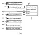
- Fig. 4shows components of a computer system of the invention. Optional components of the computer system are indicated by boxes with dashed lines.
- the computer systemprovides entries for the context menu with relationships that are applicable to relate the selected objects.
- a boxrepresents a component and a line represents an interface for exchanging data between two components.
- the computer systemincludes a receiver component 310 that is configured to receive the identifications of the selected objects.
- An optional relationship identifier component 350is configured to identify an existing relationship between the selected objects, that is, the objects of which the identifications have been received by the receiver component. The identifications of the selected objects are transferred with an interface between the receiver component 310 and the relationship identifier component 350.
- the systemfurther includes a type identifier component 320 that is configured to identify the object types of the selected objects. The identifications are again transferred with an interface between the receiver component 310 and the type identifier component 320.
- the interface between the receiver component 310 and the type identifier component 320may include the interface between the receiver component 310 and the relationship identifier component 350 and the interface between the relationship identifier component 350 and the type identifier component 320.
- the interface between the receiver component 310 and the type identifier component 320may directly connect the receiver component 310 and the type identifier component 320.
- a determiner component 330 of the systemis configured to determine a relationship type of a relationship that is applicable to the selected objects.
- the relationship typeis determined by using the object types identified by the type identifier component.
- the determiner component 330may be further configured in case more than two objects have been selected to determine a relationship type of multiple relationships.
- the multiple relationshipsare applicable to the selected objects and they relate one object of the selected objects having a first object type to residual objects of the selected objects having a second object type by creating multiple times a relationship.
- the determiner component 330may further be configured to select the relationship type from the one or more assignments that specify the identified object types.
- a generator component 340is configured to generate for the context menu an entry representing a relationship of the one or more relationship types determined by the determiner component 350. Accordingly, the relationship is selectable by the user to be applied to the selected objects.
- the generator component 340may be further configured to delete a relationship from the relationships of the one or more relationship types in case that the relationship has an attribute and that the attribute does not fulfill a restriction applicable to the relationship attribute.
- An optional further generator component 360is configured to generate for the context menu an entry which is selectable by user to maintain the identified relationship.
- Fig. 5illustrates an exemplary situation with two selected objects and a context menu.
- the exemplary situationis provided by an exemplary program for creating and maintaining an enhanced bill of material.
- a bill of materialdescribes a finished product and components of the finished product.
- the enhanced bill of materialmay further include a description of manufacturing processes for assembling the finished product.
- the bill of materialmay also refer to the enhanced bill of material.
- the exemplary programmodels the enhanced bill of material, EBOM, using nodes which represent relevant elements of a production process.
- a usage of nodesrenders a construction of the EBOM fast and flexible because nodes and substructure of nodes can be used for different EBOM.
- the usage of nodesrenders the EBOM more complex because further rules apply to the usage of nodes.
- the rulesmay or may not depend on the relevant elements that are assigned to the nodes. Providing a context menu for relationships between the EBOM may be helpful to the user.
- Examples for nodes of the EBOMare as follows: an access node to which one or more finished products are assigned, a structure node to which one or more components of a finished product are assigned, and an activity node representing a manufacturing process.
- Examples for relationships for the nodes of the EBOMare as follows: an assemble relationship which may for example describe that a component is used for an assembly of a further component, an assign relationship which may be used to assign a structure node to an access node, a process relation which may relate for example an activity node to a structure node.
- Fig. 5there are two areas separated by line.
- a first areathere is an access node 510 which represents the finished product of a bicycle.
- a structure node 515which represents the component of a frame of the bicycle is assigned to the access node 510.
- the first areais an EBOM construction and maintenance area.
- the access node 510 and the structure node 515represent a part of an EBOM.
- the second areathere are further nodes: a structure node 520 which represents a wheel fork, a structure node 525 which represents a front wheel, a structure node 530 which represents a rear wheel, an activity node 535 which represents a process to weld a frame, and an activity node 540 which represents a process to paint a frame.
- the second arearepresents a loading area from which objects for the EBOM are selected. It may be that the two areas are not separated from each other. It may also be that more than one EBOM are in the first area and one or more EBOM
- Fig. 5illustrates a situation in which the user has selected the access node 510 and the structure node 525.
- the contexthas entries generated according to an embodiment of the invention.
- the assign relationshipassigns the structure node 520 to the access node 510, that is, the structure node 520 is added to the EBOM in the first area.
- the substitute relationshipsubstitutes the access node 510 by the structure node 520.
- the substitute relationshipmay have a different relationship type than the assign relationship because a substitute relationship may for example relate all different kinds of nodes and the assign relationship may for example only relate an access node and a structure node.
- a delete relationship entry 556which deletes the selected nodes.
- There is further a copy relationship entry 558which copies the selected nodes into a separate buffer from which the selected nodes may be retrieved again.
- the delete relationship and the copy relationshipmay have an identical relationship type that is different from any one of the relationship types of the assign and substitute relationship. The reason is that the delete and copy relationships are independent from the selected nodes and the object types of the selected nodes. According to the entries of the context menu the user may select an activity.
- Fig. 6illustrates a further exemplary situation with two selected objects and a context menu.
- the displayed nodes 510 - 540 and their positionsare identical to the previous situation illustrated in Fig. 5 .
- the userhas selected the access node 510 and the structure node 515 previously to requesting the context menu 550.
- the context menuhas delete relationship entry 562, modify relationship entry 564, delete entry 566, and copy entry 568. Because the selected nodes are related by a previously created assign relationship and the embodiment of the invention has identified the relationship two entries for maintaining the identified relationship have been generated: the delete relationship entry 562 and the modify relationship entry 564. Selecting the delete relationship may delete the structure node 515 from the EBOM and add the structure node to the second area.
- Selecting the modify relationship the programmay create a further user interface so that the user can enter new data with respect to the identified relationship.
- Examples for such dataare one of the following: an attribute of the identified relationship, a multiplication value determining how many frames are related to the bicycle.
- the delete 566 and the copy 568 relationship entriesrepresent the same activities as in Fig. 5 .
- Fig. 7illustrates an exemplary situation with three selected objects and a context menu.
- the displayed nodes 510 - 540 and their positionsare identical to the previous situations illustrated in Fig. 5 and Fig. 6 .
- the userhas selected the access node 510, the structure node 520, and the activity node 540 previously to requesting the context menu 550.
- the context menuhas assign entry 572, delete entry 574, and copy entry 576.
- the assign relationship represented by entry 572is an example of a relationship that relates three selected objects. Selecting the assign entry 572 the program may assign the structure node 520 to the access node 510 and assign the activity node 540 to the structure node 520.
- the EBOMmay include two further nodes: the structure node 520 and the activity node 540.
- the structure nodes 515 and 520may be assigned as components to the access node 510 and the activity node 540 may be assigned to the structure node 520.
- the delete 574 and the copy 576 relationship entriesrepresent the same activities as in Fig. 5 and Fig. 6 .
- Fig. 8illustrates a further exemplary situation with three selected objects and a context menu.
- the displayed nodes 510 - 540 and their positionsare identical to the previous situations illustrated in Fig. 5 - 7 .
- the userhas selected the access node 510, the structure node 520, and the activity node 540 previously to requesting the context menu 550.
- the context menuhas assign entry 582, delete entry 584, and copy entry 586.
- the assign entry 582represents a multiple relationship that relates the three selected nodes with two separate assign relationships.
- the programmay create two relationships: a first assign relationship between the access node 510 and the structure node 520 and a second assign relationship between the access node 510 and the structure node 525.
- the identical resultcan be achieved in two steps by selecting the access node 510 and the structure node 520 and creating the assign relationship between the two nodes and further selecting the access node 510 and the structure node 525 and creating the assign relationship between the two nodes.
- the two stepsway is less efficient with respect to computer resources such as computation time.
- Fig. 9illustrates an exemplary situation with two selected objects and a context menu with a reduced number of entries.
- the displayed nodes 510 - 540are identical to the previous situations illustrated in Fig. 5 - 8 .
- the userhas selected the structure node 515 and the activity node 540 previously to requesting the context menu 550.
- the context menuhas delete entry 592 and copy entry 594.
- a reason for thismay be for example that only one activity node may be assigned to a structure node, that is, a cardinality attribute of an assign relationship between a structure node and an activity is zero to one.
- no further activity nodemay be assigned to the structure node 515 because the activity node 535 is already assigned to the structure node 515.
- a further assign relationship of the activity node 540does not fulfill a restriction applicable to the cardinality attribute. Accordingly the further assign relationship is deleted from the applicable relationships for which the context menu entries are generated.
- a further reasonmay be for example that the user has an authorization to add structure nodes which represent a product aspect to the EBOM but not to add activity nodes which represent a production process aspect to the EBOM.
- an authority restrictionwhich applies to the authority attribute of the assign relationship between the structure node 515 and the activity node 540 the assign relationship is deleted from the applicable relationships.
- the embodiments of the inventioncan be implemented in digital electronic circuitry, or in computer hardware, firmware, software, or in combinations of them.
- the inventioncan be implemented as a computer program product, for example, a computer program tangibly embodied in an information carrier, for example, in a machine-readable storage device or in a propagated signal, for execution by, or to control the operation of, data processing apparatus, for example, a programmable processor, a computer, or multiple computers.
- a computer programcan be written in any form of programming language, including compiled or interpreted languages, and it can be deployed in any form, including as a stand-alone program or as a module, component, subroutine, or other unit suitable for use in a computing environment.
- a computer programcan be deployed to be executed on one computer or on multiple computers at one site or distributed across multiple sites and interconnected by a communication network.
- Method steps of the embodiment of the inventioncan be performed by one or more programmable processors executing a computer program to perform functions of the invention by operating on input data and generating output. Method steps can also be performed by, and apparatus of the invention can be implemented as, special purpose logic circuitry, for example, an FPGA (field programmable gate array) or an ASIC (application-specific integrated circuit).
- FPGAfield programmable gate array
- ASICapplication-specific integrated circuit
- processors suitable for the execution of a computer programinclude, by way of example, both general and special purpose microprocessors, and any one or more processors of any kind of digital computer.
- a processorwill receive instructions and data from a read-only memory or a random access memory or both.
- the essential elements of a computerare a processor for executing instructions and one or more memory devices for storing instructions and data.
- a computerwill also include, or be operatively coupled to receive data from or transfer data to, or both, one or more mass storage devices for storing data, e.g., magnetic, magneto-optical disks, or optical disks.
- Information carriers suitable for embodying computer program instructions and datainclude all forms of non-volatile memory, including by way of example semiconductor memory devices, for example, EPROM, EEPROM, and flash memory devices; magnetic disks, for example, internal hard disks or removable disks; magneto-optical disks; and CD-ROM and DVD-ROM disks.
- semiconductor memory devicesfor example, EPROM, EEPROM, and flash memory devices
- magnetic disksfor example, internal hard disks or removable disks
- magneto-optical disksand CD-ROM and DVD-ROM disks.
- the processor and the memorycan be supplemented by, or incorporated in special purpose logic circuitry.
Landscapes
- Engineering & Computer Science (AREA)
- Theoretical Computer Science (AREA)
- General Engineering & Computer Science (AREA)
- Human Computer Interaction (AREA)
- Physics & Mathematics (AREA)
- General Physics & Mathematics (AREA)
- Data Mining & Analysis (AREA)
- Databases & Information Systems (AREA)
- User Interface Of Digital Computer (AREA)
- Table Devices Or Equipment (AREA)
- Input From Keyboards Or The Like (AREA)
Abstract
Description
- The present invention relates generally to the field of electronic data processing and specifically to provision of user interfaces to a user.
- The performance of modern computer systems has reached a high level. Accordingly, the computer systems are able to support complex computer programs. Frequently, the complex computer programs provide also complex user interfaces to a user of the complex computer programs. A complex user interface allows for the exchange of different kinds of information between the computer program and the user. Frequently, the exchanged information is dependent from other information and a dependency may not be obvious to the user.
- Typically, the complex user interface provides a graphical user interface that displays many different objects. Furthermore, the complex user interface may provide one or more devices to the user to select an object and to determine a function which is applied to the selected object. One example for such a device is a graphical pointer which is controlled by the user with a handheld pointing device, for example a computer mouse. Displayed objects and applicable functions depend on the computer program. An example is an operating system that allows for a selection of displayed files by the computer mouse and a selection of a function from a menu that is applied to the selected file.
- The number of optional activities that the user can execute with the user interface by combining inputs is typically large. In case an activity requires more than one input it is convenient to support the user by providing additional information to him.
- One way to support the user executing an activity is provided by a context menu. Typically, the user selects an object displayed by the user interface and requests the context menu. The context menu may have for example entries of functions that can be applied to the selected object. The user may select one of the listed functions and the selected function is executed for the selected object.
United States Patent, patent number 5664133 , discloses a method to support the user by providing the context menu. The user selects a first displayed computer resource and a second displayed computer resource and may request a context menu. The context menu has selectable entries associated with a transfer of the first computer resource to the second computer resource. The selectable entries may be operations that can be executed by the computer program based on the relationship of the first computer resource, that is a file, and the second computer resource, that is a folder.United States Patent, patent number 5524246 , discloses a graphic program configuration system that displays optional objects to a user in a window. The optional objects may be connection types that are selectable by the user in accordance to previously selected objects, that is, a selected outlet object and a selected subprogram. Furthermore, it is disclosed that the subprogram may be connected to outlet objects through pointers and that an outlet object may be connected to connection types also through pointers.United States Patent, patent number 5903478 , discloses a method of displaying an architecture visual model in a symbol based table. The architecture visual model has visual objects each of which is linked to at least a further visual object. The visual objects are arranged as columns or rows of the symbol based table according to object types of the visual objects. A visual symbol indicates a relationship between a visual object arranged as a column and a further visual object arranged as a row.- In computer programs displayed objects may be numerous and the displayed objects have different object types. Furthermore, relationships may also be numerous and the relationships have one or more relationship types. It is convenient to provide a context menu for such computer programs. An example for such a computer program is an operating system displaying a first object which is a file of an object type computer resource and a second object which is a file conversion program of an object type computer program. In the example, a relationship may be of a type file transfer and a further relationship may be of a type application.
- An embodiment of the invention is disclosed according to features of
claim 1. The embodiment is a method for providing a context menu with relationships that are of one or more relationship types. A relationship of the context menu is applicable to relate two objects that have been selected previously from a set of objects. The objects of the set of objects have a plurality of object types. - The embodiment is fast and memory efficient because the relationships in the context menu are generated by identifying object types and determining relationship types. Frequently, in a computer program a number of object types is smaller than a number of objects and a number of relationship types is smaller than a number of relationships. Accordingly, it requires less data processing to determine the applicable relationships by using types instead of using objects and relationships.
- The context menu has only entries with applicable relationships. Relationships that are not applicable to the selected objects are not displayed and are not processed by the computer program. Therefore, the amount of data being processed is reduced contributing to a fast and memory efficient execution of a computer program.
- The embodiment may prevent errors such as creating a relationship that is not applicable to the selected objects. Such an error may happen when for example a first object is selected, then a relationship applicable to the object is selected and then a second object is selected. In case the second object cannot be related by the selected relationship to the first object the system may try to create an invalid relationship. Even if a following check notices an error it is more efficient to prevent such an error as early as possible. An aspect of error prevention therefore also contributes to the fast execution of the computer program.
- The embodiment also contributes to the fast execution of the computer program by providing selectable context menu entries which the user may not be aware of in a current situation. By providing such knowledge, the embodiment may prevent unnecessary activities of the user.
- A further embodiment of the invention is disclosed according to features of claim 14. The further embodiment is a computer system for providing a context menu with relationships. Features of the further embodiment correspond to features of the embodiment.
- Accordingly, aspects of the further embodiment correspond to aspects of the embodiment.
Fig. 1 shows method steps of a method of the invention.Fig. 2 illustrates three successive situations displayed to a user by a user interface.Fig. 3 shows exemplary assignments and negative assignments for determining applicable relationships.Fig. 4 shows components of a computer system of the invention.Fig. 5 illustrates an exemplary situation with two selected objects and a context menu an entry for creating a relationship.Fig. 6 illustrates an exemplary situation with two selected objects and a context menu with entries for maintaining a relationship.Fig. 7 illustrates an exemplary situation with three selected objects and a context menu with relationships applicable to the selected objects.Fig. 8 illustrates an exemplary situation with three selected objects and a context menu with multiple relationships applicable to the selected objects.Fig. 9 illustrates an exemplary situation with two selected objects and a context menu with a reduced number of entries.- The following description contains examples and embodiments of the invention that are not limiting the scope of the invention.
Fig. 1 shows method steps of a method of the invention. Optional method steps of the method are indicated by boxes with dashed lines. The method provides entries for a context menu. The context menu is provided to a user that may select an entry of the context menu. The entries represent optional activities with respect to relationships. The method uses available information about a situation of the user to provide the entries. For example, the entries may represent relationships that can be applied to relate previously selected objects, that is, the relationships are applicable to the selected objects. In this way, the method supports the user in an interaction with a computer program. The objects and the applicable relationships depend on the computer program. An example for the computer program is an operating system that displays files of different types and allows for relating the files.- The computer program may display a set of objects that may be related by applicable relationships. The display of an object may involve the display of an icon representing the object. Frequently, there are dependencies between the objects and between the applicable relationships. According to the dependencies, it may not be possible to use a specific relationship to relate two objects. The user may not be aware of the dependencies and may not know if the specific relationship is applicable to the two objects. In the example, the user may request a context menu with the applicable relationships that may be selected from the context menu and are conforming to the dependencies.
- A first method step is receiving 110 a first identification of a first object which is selected by the user from a set of objects. The set of objects may be defined by objects that are displayed to the user and selectable by the user. The user may use a graphical pointer device to point to the first object and a button for selecting the first object. An example for such a graphical pointer device is a computer mouse. A request of a context menu may be done by using a further button. The selection of an entry from the context menu may be possible by using again the button which is used for selecting the objects. It depends on the computer program if a selection and the request of the context menu can be done by using the graphical pointer device. Frequently, the computer program supports the graphical pointer device. The computer program may also support selecting a displayed object by pressing repeatedly a first button to navigate an object indicator to the first object and by using a second button to select the first object. A user interface may register the selection of the first object and the computer program may provide the first identification to the method. Typically, the first object will be marked so that a selection of the first object is visible.
- A following method step is receiving 120 a second identification of a second object which is selected by the user from the set of objects. The selection of the second object may be done in an analogous way to the selection the first object.
- An optional method step is receiving 180 one or more further object identifications from the set of objects. Depending on the computer program it may be feasible to relate two objects by a relationship or more than two objects by a relationship. An example is an operating system which allows for relating a file transformation program with a first file and a second file. Relating the three files may result in transformation of the first file into the format of the second file using the file transformation program. If the computer program allows for relating only two objects it may still be convenient to receive identifications of more than two selected objects because the selected objects can possibly be related by more than one relationship.
- An optional method step checking 190 an object type condition is related to providing context menu entries for multiple relationships. Multiple relationships require that a condition is fulfilled that an object of the selected objects is of a first object type and residual objects of the selected objects are of a second object type. The multiple relationships may be created between the object of the first object type and each object of the residual objects by creating one relationship multiple times. Creating multiple relationships gives a same result as creating a single relationship separately between the object of the first object type and the each object of the residual objects. Creating the multiple relationships leads to a fast and efficient execution of the computer program.
- A following optional method step is identifying 160 an existing relationship, that is, a relationship that has been created previously between the selected objects. In case that such a relationship is identified and that no further relationship may be created between the selected objects it may be possible to skip some of the following method steps.
- A following method step is identifying 130 object types of the selected objects, wherein the object types are from a plurality of object types. In the example, the file conversion program may have an object type application program. The first file and the second file may have object type computer resource. Other object types may be possible which type the objects from the set of objects.
- It follows determining 140 one or more relationship types of which a relationship is applicable to the selected objects. The determining step involves the identified object types and does not require an identification of a selected object. Accordingly, the determining step is independent of the number of the objects in the set of objects and the number of available relationships. The determining step depends on the number of object types of objects of the set and relationship types. It may be possible to define the object types and the relationship types so that the dependencies between the objects and the applicable relationships can directly be described. As an example, it may be possible to define an object type for file conversion programs that require one file and a further object type for file conversion programs that require two files. In the example, selecting a file and the file conversion program requiring two files may not give an entry in the context menu for applying the file conversion program to the file: a relationship type for applying the file conversion program may not be determined because the object type of the file conversion program requires two file object types. In a further example, the object types and the relationship types may be defined by the computer program and may not directly be used to describe the dependencies. In such cases, a following optional step may be conveniently executed.
- It follows method step generating 150 an entry for the context menu. The entry represents a relationship of the one or more determined relationship types. The relationship is selectable by the user so that it is created between the selected objects.
- Generating
step 150 may optionally include a step of deleting 210 a relationship. The relationship may be of the one or more relationship types that have been determined but may have an attribute and the attribute may not fulfill a restriction. No entry for the context menu is generated for a deleted relationship. The optional deletingstep 210 may be useful when object types and relationship types are insufficient to describe the dependencies between the objects and the applicable relationships. In such cases, restrictions applicable to relationship attributes may be used to describe the dependencies in further detail. As an example, it may be possible that a first file conversion program which is applied to one file and a second file conversion program which is applied to two files are of the same relationship type. Accordingly, an apply relationship which applies a file conversion program may be determined even if the second file conversion program and one file have been selected, that is, the apply relationship is not applicable to the selected objects. In such a case the apply relationship may have an attribute specifying the number of the files to which the file conversion program is applied. In the example, the attribute may have the value one because only one file has been selected. A restriction depending on the file conversion program is applied to the attribute of the relationship. The restriction for the second file conversion program may be that two files are to be selected. Accordingly, the restriction is not fulfilled by the apply relationship and the apply relationship is deleted. - It follows an optional step generating 170 an entry for the context menu, wherein the entry is selectable to maintain an identified relationship. This method step requires previously executing the step identifying 160 a created relationship. Maintaining the relationship may mean deleting the relationship or modifying an attribute of the relationship. The step generating 170 a maintaining relationship entry may be executed previously to the step generating 150 the creating relationship entry because the two steps are independent from each other.
- It follows optional step generating 200 for the context menu an entry representing multiple relationships of the one or more relationship types. This method step requires previously executing the step checking 190 the object type condition. The multiple relationships are selectable by the user to be created between the one object of the first object type and the residual objects of the second object type. The step generating 170 the multiple relationships entry may be executed previously to the step generating 150 the creating relationship entry and previously to the step generating 170 a maintaining relationship entry.
Fig. 2 illustrates three successive situations displayed to the user by a user interface. The three situations illustrate a typical sequence of displays that result from an interaction of the user with the computer program.Fig. 2A shows a set of objects 231-237 having three different object types.Objects Fig. 2B shows the set of objects 231-237 after the user has selected afirst object 231 and asecond object 237. The selected objects are visibly marked by double lines.Fig. 2C shows the display of the user interface after the user has requested thecontext menu 240. Thecontext menu 240 has twoentries entries first object 231 and thesecond object 237. It may be possible that the two relationships are of one relationship type or of two relationship types. Frequently, the user may not be aware of such differences.Fig. 3 shows exemplary assignments and negative assignments for determining applicable relationships. A table ofassignments 250 contains exemplary assignments 252-258. The assignments 252-258 assign relationship types to a plurality of object types signifying that a relationship of the relationship types is applicable to relate a plurality of objects having object types that are specified by the assignments. In the example,assignment 252 relates a relationship type RST1 to two object types OT1 and OT2. Objects of object type OT1 may be for example the objects 231-233 (Fig. 2 ) with the square shape and objects of object type OT2 may be for example theobjects 234 and 235 (Fig. 2 ) with the circle shape. Theassignment 252 specifies that a relationship having relationship type RST1 is applicable to relate an object having object type OT1 and a further object having object type OT2. Having for example a plurality of identified object types OT1 and OT2 from selected objects it follows fromassignment 252 that relations of relationship type RST1 are applicable to relate the selected objects. Assignments 254-258 specify different object type combinations and assign the combinations to a relationship type RST2. In case that more than one assignment specifies one combination of object types it follows that a combination of objects having object types specified by the one combination can be related by one or more relationships of more than one relationship type.- A table of
negative assignments 260 contains exemplary negative assignments 262-268. The negative assignments 262-268 assign a relationship type to a plurality of object types signifying that a relationship of the relationship type is not applicable to relate a plurality of objects having object types that are specified by the negative assignments. In the example,negative assignment 262 relates a relationship type RST2 to two object types OT1 and OT2. Theassignment 262 specifies that a relationship having relationship type RST1 is not applicable to relate an object having object type OT1 and a further object having object type OT2. The negative assignment may be used in case that a number of assignments is large because objects of many object types may be related by relationships of many relationship types. In such a case a number of negative assignments may be small. Determining 140 one or more relationship types may include for example determining a set of all relationship types available to the computer program and use the negative assignments to delete a relationship type from the set. Depending on the computer program this may result in a low memory requirement and a fast execution of the method. Fig. 4 shows components of a computer system of the invention. Optional components of the computer system are indicated by boxes with dashed lines. The computer system provides entries for the context menu with relationships that are applicable to relate the selected objects. InFig. 4 , a box represents a component and a line represents an interface for exchanging data between two components. The computer system includes areceiver component 310 that is configured to receive the identifications of the selected objects. An optionalrelationship identifier component 350 is configured to identify an existing relationship between the selected objects, that is, the objects of which the identifications have been received by the receiver component. The identifications of the selected objects are transferred with an interface between thereceiver component 310 and therelationship identifier component 350. The system further includes atype identifier component 320 that is configured to identify the object types of the selected objects. The identifications are again transferred with an interface between thereceiver component 310 and thetype identifier component 320. The interface between thereceiver component 310 and thetype identifier component 320 may include the interface between thereceiver component 310 and therelationship identifier component 350 and the interface between therelationship identifier component 350 and thetype identifier component 320. In a further example, the interface between thereceiver component 310 and thetype identifier component 320 may directly connect thereceiver component 310 and thetype identifier component 320. Adeterminer component 330 of the system is configured to determine a relationship type of a relationship that is applicable to the selected objects. The relationship type is determined by using the object types identified by the type identifier component. Thedeterminer component 330 may be further configured in case more than two objects have been selected to determine a relationship type of multiple relationships. The multiple relationships are applicable to the selected objects and they relate one object of the selected objects having a first object type to residual objects of the selected objects having a second object type by creating multiple times a relationship. Thedeterminer component 330 may further be configured to select the relationship type from the one or more assignments that specify the identified object types. Agenerator component 340 is configured to generate for the context menu an entry representing a relationship of the one or more relationship types determined by thedeterminer component 350. Accordingly, the relationship is selectable by the user to be applied to the selected objects. Thegenerator component 340 may be further configured to delete a relationship from the relationships of the one or more relationship types in case that the relationship has an attribute and that the attribute does not fulfill a restriction applicable to the relationship attribute. An optionalfurther generator component 360 is configured to generate for the context menu an entry which is selectable by user to maintain the identified relationship.Fig. 5 illustrates an exemplary situation with two selected objects and a context menu. The exemplary situation is provided by an exemplary program for creating and maintaining an enhanced bill of material. A bill of material describes a finished product and components of the finished product. The enhanced bill of material may further include a description of manufacturing processes for assembling the finished product. The bill of material may also refer to the enhanced bill of material. The exemplary program models the enhanced bill of material, EBOM, using nodes which represent relevant elements of a production process. A usage of nodes renders a construction of the EBOM fast and flexible because nodes and substructure of nodes can be used for different EBOM. On the other hand, the usage of nodes renders the EBOM more complex because further rules apply to the usage of nodes. The rules may or may not depend on the relevant elements that are assigned to the nodes. Providing a context menu for relationships between the EBOM may be helpful to the user.- Examples for nodes of the EBOM are as follows: an access node to which one or more finished products are assigned, a structure node to which one or more components of a finished product are assigned, and an activity node representing a manufacturing process. Examples for relationships for the nodes of the EBOM are as follows: an assemble relationship which may for example describe that a component is used for an assembly of a further component, an assign relationship which may be used to assign a structure node to an access node, a process relation which may relate for example an activity node to a structure node.
- In
Fig. 5 there are two areas separated by line. In a first area there is anaccess node 510 which represents the finished product of a bicycle. Astructure node 515 which represents the component of a frame of the bicycle is assigned to theaccess node 510. The first area is an EBOM construction and maintenance area. Theaccess node 510 and thestructure node 515 represent a part of an EBOM. In the second area there are further nodes: astructure node 520 which represents a wheel fork, astructure node 525 which represents a front wheel, astructure node 530 which represents a rear wheel, anactivity node 535 which represents a process to weld a frame, and anactivity node 540 which represents a process to paint a frame. The second area represents a loading area from which objects for the EBOM are selected. It may be that the two areas are not separated from each other. It may also be that more than one EBOM are in the first area and one or more EBOM are in the second area. Fig. 5 illustrates a situation in which the user has selected theaccess node 510 and thestructure node 525. Upon the selection of the two nodes the user has requested acontext menu 550. The context has entries generated according to an embodiment of the invention. There are an assignrelationship entry 552, asubstitute relationship entry 554, adelete relationship entry 556, and acopy relationship entry 558. The assign relationship assigns thestructure node 520 to theaccess node 510, that is, thestructure node 520 is added to the EBOM in the first area. The substitute relationship substitutes theaccess node 510 by thestructure node 520. The substitute relationship may have a different relationship type than the assign relationship because a substitute relationship may for example relate all different kinds of nodes and the assign relationship may for example only relate an access node and a structure node. In thecontext menu 550 there is adelete relationship entry 556 which deletes the selected nodes. There is further acopy relationship entry 558 which copies the selected nodes into a separate buffer from which the selected nodes may be retrieved again. The delete relationship and the copy relationship may have an identical relationship type that is different from any one of the relationship types of the assign and substitute relationship. The reason is that the delete and copy relationships are independent from the selected nodes and the object types of the selected nodes. According to the entries of the context menu the user may select an activity.Fig. 6 illustrates a further exemplary situation with two selected objects and a context menu. The displayed nodes 510 - 540 and their positions are identical to the previous situation illustrated inFig. 5 . However, the user has selected theaccess node 510 and thestructure node 515 previously to requesting thecontext menu 550. According to the embodiment of the invention the context menu has deleterelationship entry 562, modifyrelationship entry 564, deleteentry 566, andcopy entry 568. Because the selected nodes are related by a previously created assign relationship and the embodiment of the invention has identified the relationship two entries for maintaining the identified relationship have been generated: thedelete relationship entry 562 and the modifyrelationship entry 564. Selecting the delete relationship may delete thestructure node 515 from the EBOM and add the structure node to the second area. Selecting the modify relationship the program may create a further user interface so that the user can enter new data with respect to the identified relationship. Examples for such data are one of the following: an attribute of the identified relationship, a multiplication value determining how many frames are related to the bicycle. The delete 566 and thecopy 568 relationship entries represent the same activities as inFig. 5 .Fig. 7 illustrates an exemplary situation with three selected objects and a context menu. The displayed nodes 510 - 540 and their positions are identical to the previous situations illustrated inFig. 5 andFig. 6 . However, the user has selected theaccess node 510, thestructure node 520, and theactivity node 540 previously to requesting thecontext menu 550. According to the embodiment of the invention the context menu has assignentry 572, deleteentry 574, andcopy entry 576. The assign relationship represented byentry 572 is an example of a relationship that relates three selected objects. Selecting the assignentry 572 the program may assign thestructure node 520 to theaccess node 510 and assign theactivity node 540 to thestructure node 520. Therefore, after the assign the EBOM may include two further nodes: thestructure node 520 and theactivity node 540. After the assign, thestructure nodes access node 510 and theactivity node 540 may be assigned to thestructure node 520. The delete 574 and thecopy 576 relationship entries represent the same activities as inFig. 5 andFig. 6 .Fig. 8 illustrates a further exemplary situation with three selected objects and a context menu. The displayed nodes 510 - 540 and their positions are identical to the previous situations illustrated inFig. 5 - 7 . However, the user has selected theaccess node 510, thestructure node 520, and theactivity node 540 previously to requesting thecontext menu 550. According to the embodiment of the invention the context menu has assignentry 582, deleteentry 584, andcopy entry 586. The assignentry 582 represents a multiple relationship that relates the three selected nodes with two separate assign relationships. Selecting the multiple assignrelationship entry 572 the program may create two relationships: a first assign relationship between theaccess node 510 and thestructure node 520 and a second assign relationship between theaccess node 510 and thestructure node 525. The identical result can be achieved in two steps by selecting theaccess node 510 and thestructure node 520 and creating the assign relationship between the two nodes and further selecting theaccess node 510 and thestructure node 525 and creating the assign relationship between the two nodes. However, the two steps way is less efficient with respect to computer resources such as computation time.Fig. 9 illustrates an exemplary situation with two selected objects and a context menu with a reduced number of entries. The displayed nodes 510 - 540 are identical to the previous situations illustrated inFig. 5 - 8 . The user has selected thestructure node 515 and theactivity node 540 previously to requesting thecontext menu 550. According to the embodiment of the invention the context menu has deleteentry 592 andcopy entry 594. There is no entry for representing an assign relationship. A reason for this may be for example that only one activity node may be assigned to a structure node, that is, a cardinality attribute of an assign relationship between a structure node and an activity is zero to one. Therefore, no further activity node may be assigned to thestructure node 515 because theactivity node 535 is already assigned to thestructure node 515. A further assign relationship of theactivity node 540 does not fulfill a restriction applicable to the cardinality attribute. Accordingly the further assign relationship is deleted from the applicable relationships for which the context menu entries are generated. A further reason may be for example that the user has an authorization to add structure nodes which represent a product aspect to the EBOM but not to add activity nodes which represent a production process aspect to the EBOM. According to an authority restriction which applies to the authority attribute of the assign relationship between thestructure node 515 and theactivity node 540 the assign relationship is deleted from the applicable relationships.- The embodiments of the invention can be implemented in digital electronic circuitry, or in computer hardware, firmware, software, or in combinations of them. The invention can be implemented as a computer program product, for example, a computer program tangibly embodied in an information carrier, for example, in a machine-readable storage device or in a propagated signal, for execution by, or to control the operation of, data processing apparatus, for example, a programmable processor, a computer, or multiple computers. A computer program can be written in any form of programming language, including compiled or interpreted languages, and it can be deployed in any form, including as a stand-alone program or as a module, component, subroutine, or other unit suitable for use in a computing environment. A computer program can be deployed to be executed on one computer or on multiple computers at one site or distributed across multiple sites and interconnected by a communication network.
- Method steps of the embodiment of the invention can be performed by one or more programmable processors executing a computer program to perform functions of the invention by operating on input data and generating output. Method steps can also be performed by, and apparatus of the invention can be implemented as, special purpose logic circuitry, for example, an FPGA (field programmable gate array) or an ASIC (application-specific integrated circuit).
- Processors suitable for the execution of a computer program include, by way of example, both general and special purpose microprocessors, and any one or more processors of any kind of digital computer. Generally, a processor will receive instructions and data from a read-only memory or a random access memory or both. The essential elements of a computer are a processor for executing instructions and one or more memory devices for storing instructions and data. Generally, a computer will also include, or be operatively coupled to receive data from or transfer data to, or both, one or more mass storage devices for storing data, e.g., magnetic, magneto-optical disks, or optical disks. Information carriers suitable for embodying computer program instructions and data include all forms of non-volatile memory, including by way of example semiconductor memory devices, for example, EPROM, EEPROM, and flash memory devices; magnetic disks, for example, internal hard disks or removable disks; magneto-optical disks; and CD-ROM and DVD-ROM disks. The processor and the memory can be supplemented by, or incorporated in special purpose logic circuitry.
Claims (17)
- A computer implemented method for providing to a user a context menu (240) with entries representing relationships (241, 242), wherein the relationships (241, 242) are applicable to relate objects (231, 237) selected from a set of objects; the method comprising:receiving (110) a first identification of a first selected object (231) from the set of objects;receiving (120) a second identification of a second selected object (237) from the set of objects;identifying (130) object types of the selected objects (231, 237) in a plurality of object types;determining (140) one or more relationship types of which one or more relationships are applicable to the selected objects (231, 237) by using the identified object types and by selecting the one or more relationship types from one or more assignments (252-258) that specify the identified object types, an assignment which assigns a relationship type to a plurality ofobject types signifying that a relationship of the relationship type is applicable to relate a plurality of objects having object types that are specified by the assignment; andgenerating (150) for the context menu an entry (241, 242) representing a relationship of the one or more relationship types, wherein the relationship is selectable by the user to be created between the selected objects (231, 237).
- The method of claim 1 further comprising:identifying (160) a relationship that has been created previously between the selected objects (510, 515);generating (170) for the context menu (550) an entry (562, 564) which is selectable by the user to maintain the identified relationship.
- The method of claim 2 wherein maintaining the identified relationship means deleting (562) the identified relationship.
- The method of claim 2 wherein maintaining the identified relationship means modifying (564) an attribute of the identified relationship.
- The method of any one of the previous claims further comprising: upon having received (120) the second identification of the second object, receiving (180) one or more further identifications of selected objects from the set of objects.
- The method of claim 5 further comprising:checking (190) if one object (510) of the selected objects (510, 520, 525) is of a first object type and if residual objects (520, 525) of the selected objects are of a second object type;generating (200) for the context menu (550) an entry (582) representing multiple relationships of the one or more relationship types, wherein the multiple relationships are selectable by the user to create multiple times a relationship between the one object (510) of the first object type and the residual objects (520, 525) of the second object type.
- The method of any one of the claims 1 to 6 wherein determining the one or more relationship types comprises:selecting the one or more relationship types from a set of relationship types; anddeleting a selected relationship type that is specified by a negative assignment (262-268), wherein the negative assignment which assigns a relationship type to a plurality of object types signifies that a relationship of the relationship type is not applicable to relate a plurality of objects having object types that are specified by the negative assignment.
- The method of any one of the previous claims wherein generating the entry for the context menu further comprises deleting (210) a relationship of the one or more relationship types in case that the relationship has an attribute and that the attribute does not fulfill a restriction applicable to the attribute.
- The method of any one of the previous claims wherein the objects comprise nodes (510-540) representing items of a bill of material and the relationships comprise relationships between the nodes.
- The method of claim 9 wherein a node (510-540) is any one of the following nodes: an access node (510) to which one or more finished products are assigned, a structure node (515-530) to which one or more components of a finished product are assigned, an activity node (535, 540) representing a manufacturing process.
- The method of claim 9 or 10 wherein a relationship is any one of the following relationships: assemble, assign, process, substitute.
- The method of any one of the claims 9 to 11 wherein an attribute of a relationship is one of the following attributes: cardinality specifying a number or a range of numbers for relationships to a node, authority requirement for creation of a relationship.
- A computer system for providing to a user a context menu (240) with relationships (241, 242), wherein the relationships (241, 242) are applicable to relate objects (231, 237) selected from a set of objects; the system comprising:a receiver component (310) configured to receive identifications of selected objects (231, 237) from the set of objects;a type identifier component (320) configured to identify object types of the selected objects (231, 237) of which identifications have been received by the receiver component;a determiner component (330) configured to determine one or more relationship types of one or more relationships that are applicable to the selected objects(231, 237), the one or more relationship types being determined by using the object types identified by the type identifier component and by selecting the one or more relationship types from one or more assignments (252-258) that specify the object types identified by the type identifier component, an assignment which assigns a relationship type to a plurality of object types signifying that a relationship of the relationship type is applicable to relate a plurality of objects having object types that are specified by the assignment; anda generator component (340) configured to generate for the context menu an entry (241, 242) representing a relationship of the one or more relationship types, wherein the relationship is selectable by the user.
- The system of claim 13 further comprising:a relationship identifier component (350) configured to identify an existing relationship between the selected objects (510, 515);a further generator component (360) configured to generate for the context (550) menu an entry (562, 564) which is selectable by user to maintain the identified relationship.
- The system of claim 13 or 14 wherein the determiner component is configured in case that more than two objects have been selected to determine a relationship type of multiple relationships that are applicable to the selected objects, wherein the multiple relationships relate one object of the selected objects having a first object type to residual objects of the selected objects having a second object type by creating multiple times a relationship.
- The system of any one of the claims 13 to 15 wherein the generator component is further configured to delete a relationship from the relationships of the one or more relationship types in case that the relationship has an attribute and that the attribute does not fulfill a restriction applicable to a relationship attribute.
- A computer program product with computer instructions that cause a computer system to perform any one of the method claims 1 to 12 when the computer system executes the computer instructions.
Priority Applications (4)
| Application Number | Priority Date | Filing Date | Title |
|---|---|---|---|
| EP05100979AEP1691277B1 (en) | 2005-02-11 | 2005-02-11 | Context menu providing dependency relationships for objects of different type |
| DE602005015076TDE602005015076D1 (en) | 2005-02-11 | 2005-02-11 | Context menu that provides dependency relationships for items of various kinds |
| AT05100979TATE434787T1 (en) | 2005-02-11 | 2005-02-11 | CONTEXT MENU PROVIDING DEPENDENCY RELATIONSHIPS FOR ITEMS OF DIFFERENT TYPES |
| US11/351,397US8782554B2 (en) | 2005-02-11 | 2006-02-10 | Context menu dependency on many objects of different type |
Applications Claiming Priority (1)
| Application Number | Priority Date | Filing Date | Title |
|---|---|---|---|
| EP05100979AEP1691277B1 (en) | 2005-02-11 | 2005-02-11 | Context menu providing dependency relationships for objects of different type |
Publications (2)
| Publication Number | Publication Date |
|---|---|
| EP1691277A1 EP1691277A1 (en) | 2006-08-16 |
| EP1691277B1true EP1691277B1 (en) | 2009-06-24 |
Family
ID=34938699
Family Applications (1)
| Application Number | Title | Priority Date | Filing Date |
|---|---|---|---|
| EP05100979AExpired - LifetimeEP1691277B1 (en) | 2005-02-11 | 2005-02-11 | Context menu providing dependency relationships for objects of different type |
Country Status (4)
| Country | Link |
|---|---|
| US (1) | US8782554B2 (en) |
| EP (1) | EP1691277B1 (en) |
| AT (1) | ATE434787T1 (en) |
| DE (1) | DE602005015076D1 (en) |
Families Citing this family (13)
| Publication number | Priority date | Publication date | Assignee | Title |
|---|---|---|---|---|
| US7783672B2 (en)* | 2003-04-09 | 2010-08-24 | Microsoft Corporation | Support mechanisms for improved group policy management user interface |
| USD615546S1 (en)* | 2008-03-28 | 2010-05-11 | Sprint Communications Company L.P. | Mobile device user interface |
| KR100980683B1 (en)* | 2008-09-01 | 2010-09-08 | 삼성전자주식회사 | Method and apparatus for providing a user interface for generating a menu list of a mobile terminal |
| KR20110121888A (en)* | 2010-05-03 | 2011-11-09 | 삼성전자주식회사 | Apparatus and method for checking a pop-up menu on a portable terminal |
| US10248439B2 (en)* | 2011-11-10 | 2019-04-02 | Microsoft Technology Licensing, Llc | Format object task pane |
| CA2918459C (en)* | 2013-07-16 | 2019-06-04 | Pinterest, Inc. | Object based contextual menu controls |
| US9558017B2 (en) | 2014-03-18 | 2017-01-31 | Sap Se | Software dependency management through declarative constraints |
| USD749115S1 (en)* | 2015-02-20 | 2016-02-09 | Translate Abroad, Inc. | Mobile device with graphical user interface |
| US10353541B1 (en)* | 2015-03-27 | 2019-07-16 | Open Text Corporation | Context menu fragment management |
| GB2559530B (en)* | 2015-11-30 | 2021-11-03 | Jpmorgan Chase Bank Na | Systems and methods for software security scanning employing a scan quality index |
| CN111367918B (en)* | 2020-03-05 | 2022-08-19 | 西南交通大学 | Subway vehicle maintenance BOM generation method based on EBOM |
| US12147643B2 (en) | 2020-06-10 | 2024-11-19 | Snap Inc. | Contextual action bar |
| US11368373B2 (en)* | 2020-06-16 | 2022-06-21 | Citrix Systems, Inc. | Invoking microapp actions from user applications |
Family Cites Families (62)
| Publication number | Priority date | Publication date | Assignee | Title |
|---|---|---|---|---|
| US4905162A (en)* | 1987-03-30 | 1990-02-27 | Digital Equipment Corporation | Evaluation system for determining analogy and symmetric comparison among objects in model-based computation systems |
| US4905163A (en)* | 1988-10-03 | 1990-02-27 | Minnesota Mining & Manufacturing Company | Intelligent optical navigator dynamic information presentation and navigation system |
| WO1991002304A1 (en)* | 1989-08-03 | 1991-02-21 | International Business Machines Corporation | Data processing system |
| US5295242A (en)* | 1990-11-02 | 1994-03-15 | Consilium, Inc. | Apparatus and method for viewing relationships in a factory management system |
| US5539870A (en)* | 1992-10-05 | 1996-07-23 | International Business Machines Corporation | Computerized system and process for interactively managing a distributed database system |
| CA2128387C (en)* | 1993-08-23 | 1999-12-28 | Daniel F. Hurley | Method and apparatus for configuring computer programs from available subprograms |
| US6606101B1 (en)* | 1993-10-25 | 2003-08-12 | Microsoft Corporation | Information pointers |
| US5664133A (en)* | 1993-12-13 | 1997-09-02 | Microsoft Corporation | Context sensitive menu system/menu behavior |
| US5491783A (en)* | 1993-12-30 | 1996-02-13 | International Business Machines Corporation | Method and apparatus for facilitating integrated icon-based operations in a data processing system |
| US5831606A (en)* | 1994-12-13 | 1998-11-03 | Microsoft Corporation | Shell extensions for an operating system |
| US5838317A (en)* | 1995-06-30 | 1998-11-17 | Microsoft Corporation | Method and apparatus for arranging displayed graphical representations on a computer interface |
| US6493006B1 (en)* | 1996-05-10 | 2002-12-10 | Apple Computer, Inc. | Graphical user interface having contextual menus |
| US5796401A (en)* | 1996-08-09 | 1998-08-18 | Winer; Peter W. | System for designing dynamic layouts adaptable to various display screen sizes and resolutions |
| US5818444A (en)* | 1996-08-14 | 1998-10-06 | International Business Machines Corporation | Method, apparatus and application for object selective but global attribute modification |
| US5903478A (en)* | 1997-03-10 | 1999-05-11 | Ncr Corporation | Method for displaying an IT (Information Technology) architecture visual model in a symbol-based decision rational table |
| US6035342A (en)* | 1997-03-19 | 2000-03-07 | Microsoft Corporation | Method and computer program product for implementing object relationships |
| US6956574B1 (en)* | 1997-07-10 | 2005-10-18 | Paceworks, Inc. | Methods and apparatus for supporting and implementing computer based animation |
| US5995973A (en)* | 1997-08-29 | 1999-11-30 | International Business Machines Corporation | Storing relationship tables identifying object relationships |
| US6097382A (en)* | 1998-05-12 | 2000-08-01 | Silverstream Software, Inc. | Method and apparatus for building an application interface |
| US6370537B1 (en)* | 1999-01-14 | 2002-04-09 | Altoweb, Inc. | System and method for the manipulation and display of structured data |
| US6401096B1 (en)* | 1999-03-26 | 2002-06-04 | Paul Zellweger | Method and apparatus for generating user profile reports using a content menu |
| US7272815B1 (en)* | 1999-05-17 | 2007-09-18 | Invensys Systems, Inc. | Methods and apparatus for control configuration with versioning, security, composite blocks, edit selection, object swapping, formulaic values and other aspects |
| US6978269B1 (en)* | 1999-07-13 | 2005-12-20 | International Business Machines Corporation | Apparatus and method for generating and displaying a schema diagram for a database |
| US6957229B1 (en)* | 2000-01-10 | 2005-10-18 | Matthew Graham Dyor | System and method for managing personal information |
| US20010042099A1 (en)* | 2000-02-02 | 2001-11-15 | Doongo Technologies, Inc. | Apparatus and methods for optimizing traffic volume in wireless email communications |
| US6829615B2 (en)* | 2000-02-25 | 2004-12-07 | International Business Machines Corporation | Object type relationship graphical user interface |
| US6636250B1 (en)* | 2000-04-12 | 2003-10-21 | Emc Corp | Methods and apparatus for presenting information to a user of a computer system |
| US6842748B1 (en)* | 2000-04-14 | 2005-01-11 | Rightnow Technologies, Inc. | Usage based strength between related information in an information retrieval system |
| US7730072B2 (en)* | 2000-04-14 | 2010-06-01 | Rightnow Technologies, Inc. | Automated adaptive classification system for knowledge networks |
| US6640221B1 (en)* | 2000-07-10 | 2003-10-28 | Sas Institute Inc. | System and method for configuring, sequencing and viewing joins in a query |
| US7017123B2 (en)* | 2000-12-27 | 2006-03-21 | National Instruments Corporation | Graphical user interface including palette windows with an improved search function |
| US6744451B1 (en)* | 2001-01-25 | 2004-06-01 | Handspring, Inc. | Method and apparatus for aliased item selection from a list of items |
| US7158971B1 (en)* | 2001-03-07 | 2007-01-02 | Thomas Layne Bascom | Method for searching document objects on a network |
| US6957389B2 (en)* | 2001-04-09 | 2005-10-18 | Microsoft Corp. | Animation on-object user interface |
| EP1331553A1 (en)* | 2001-06-08 | 2003-07-30 | Sap Ag | Method and computer system for graphical assignments in hierarchies |
| US6950988B1 (en)* | 2001-06-11 | 2005-09-27 | Handspring, Inc. | Multi-context iterative directory filter |
| KR100405048B1 (en)* | 2001-09-10 | 2003-11-07 | 주식회사 케이티프리텔 | System and method for modifying display formation of mobile phone |
| US20030065488A1 (en)* | 2001-09-25 | 2003-04-03 | Lockheed Martin Corporation | Distributed system and method for computer aided multi-component system design |
| US7620912B1 (en)* | 2001-10-25 | 2009-11-17 | Adobe Systems Incorporated | Graphical assignment of object behaviors |
| CA2360645C (en)* | 2001-10-31 | 2006-03-07 | Ibm Canada Limited-Ibm Canada Limitee | Dynamic generic framework for distributed tooling |
| US7058902B2 (en)* | 2002-07-30 | 2006-06-06 | Microsoft Corporation | Enhanced on-object context menus |
| US6871108B2 (en)* | 2002-11-19 | 2005-03-22 | Qssolutions, Inc. | System and method for creating a representation of an assembly |
| AU2002953500A0 (en)* | 2002-12-20 | 2003-01-09 | Redbank Manor Pty Ltd | A system and method of requesting, viewing and acting on search results in a time-saving manner |
| US7523133B2 (en)* | 2002-12-20 | 2009-04-21 | Oracle International Corporation | Data model and applications |
| US7103600B2 (en)* | 2003-03-06 | 2006-09-05 | Thought Inc. | Displayable presentation page and SQL searchable relational data source implementation of a system, method and software for creating or maintaining distributed transparent persistence of complex data objects and their data relationships |
| US7167862B2 (en)* | 2003-03-10 | 2007-01-23 | Ward Mullins | Session bean implementation of a system, method and software for creating or maintaining distributed transparent persistence of complex data objects and their data relationships |
| US7627552B2 (en)* | 2003-03-27 | 2009-12-01 | Microsoft Corporation | System and method for filtering and organizing items based on common elements |
| US7290219B2 (en)* | 2003-04-28 | 2007-10-30 | International Business Machines Corporation | System and method for selection based action bar |
| US6983187B2 (en)* | 2003-08-14 | 2006-01-03 | Sap Aktiengesellschaft | Method and system for automatically generating selection conditions in a product configuration system |
| US8051389B2 (en)* | 2003-08-26 | 2011-11-01 | Hewlett-Packard Development Company, L.P. | Methods of displaying resources of overlapping but separate hierarchies |
| US7181463B2 (en)* | 2003-10-24 | 2007-02-20 | Microsoft Corporation | System and method for managing data using static lists |
| US20050108620A1 (en)* | 2003-11-19 | 2005-05-19 | Microsoft Corporation | Method and system for selecting and manipulating multiple objects |
| US7900160B2 (en)* | 2003-12-29 | 2011-03-01 | International Business Machines Corporation | System and method for illustrating a menu of insights associated with visualizations |
| US7346621B2 (en)* | 2004-05-14 | 2008-03-18 | Microsoft Corporation | Method and system for ranking objects based on intra-type and inter-type relationships |
| JP4579030B2 (en)* | 2004-06-02 | 2010-11-10 | 株式会社リコー | Information processing apparatus, file processing method, file processing program, and recording medium |
| US8595687B2 (en)* | 2004-06-23 | 2013-11-26 | Broadcom Corporation | Method and system for providing text information in an application framework for a wireless device |
| US7475384B2 (en)* | 2004-10-19 | 2009-01-06 | Microsoft Corporation | Binding to types |
| US20060149731A1 (en)* | 2005-01-05 | 2006-07-06 | Schirmer Andrew L | System and method for deriving affinity relationships between objects |
| US7475350B2 (en)* | 2005-02-02 | 2009-01-06 | International Business Machines Corporation | Method and system to layout topology objects |
| EP1691262A1 (en)* | 2005-02-11 | 2006-08-16 | Sap Ag | Extending context awareness to support multi-file operations |
| US7571387B1 (en)* | 2005-09-21 | 2009-08-04 | Emc Corporation | Methods and apparatus facilitating management of a SAN |
| US7503009B2 (en)* | 2005-12-29 | 2009-03-10 | Sap Ag | Multifunctional icon in icon-driven computer system |
- 2005
- 2005-02-11EPEP05100979Apatent/EP1691277B1/ennot_activeExpired - Lifetime
- 2005-02-11ATAT05100979Tpatent/ATE434787T1/ennot_activeIP Right Cessation
- 2005-02-11DEDE602005015076Tpatent/DE602005015076D1/ennot_activeExpired - Lifetime
- 2006
- 2006-02-10USUS11/351,397patent/US8782554B2/enactiveActive
Also Published As
| Publication number | Publication date |
|---|---|
| ATE434787T1 (en) | 2009-07-15 |
| EP1691277A1 (en) | 2006-08-16 |
| US8782554B2 (en) | 2014-07-15 |
| US20060184898A1 (en) | 2006-08-17 |
| DE602005015076D1 (en) | 2009-08-06 |
Similar Documents
| Publication | Publication Date | Title |
|---|---|---|
| US8782554B2 (en) | Context menu dependency on many objects of different type | |
| US9275029B2 (en) | Automated form layout based upon usage patterns | |
| TWI531953B (en) | Temporary formatting and charting of selected data | |
| US20070250295A1 (en) | Multidimensional modeling system and related method | |
| US11693873B2 (en) | Systems and methods for using entity/relationship model data to enhance user interface engine | |
| US20050268280A1 (en) | Encapsulating changes to a software application | |
| US20120124492A1 (en) | Display and Resolution of Incompatible Layout Constraints | |
| US20140380178A1 (en) | Displaying interactive charts on devices with limited resources | |
| CN113986426B (en) | Image detection method and device, readable medium and electronic equipment | |
| US20080104529A1 (en) | Draggable legends for sql driven graphs | |
| EP1691262A1 (en) | Extending context awareness to support multi-file operations | |
| CN112748923A (en) | Method and device for creating visual billboard, electronic equipment and storage medium | |
| US7673245B2 (en) | Converting user interface panels | |
| WO2016099317A1 (en) | Method and system for the visual management of data | |
| CN113849175A (en) | A code generation method, device, device and storage medium | |
| CN111797125A (en) | Report creating method and device, electronic equipment and computer readable storage medium | |
| US20180004374A1 (en) | Process visualization toolkit | |
| TW200406692A (en) | Semiconductor test data analysis system | |
| JPH06348766A (en) | Method and device for incorporating tool | |
| CN117215556A (en) | Modularized page rapid construction method, system, equipment and medium | |
| US20040169684A1 (en) | Linking images for navigation | |
| US9864739B1 (en) | Automatic layout of graphical user interface screens from object data | |
| JP2007293785A (en) | Program specification-defining method | |
| CN115455876B (en) | Method for debugging logic system design and electronic equipment | |
| US12154195B2 (en) | Visualization of relationships among order components |
Legal Events
| Date | Code | Title | Description |
|---|---|---|---|
| PUAI | Public reference made under article 153(3) epc to a published international application that has entered the european phase | Free format text:ORIGINAL CODE: 0009012 | |
| AK | Designated contracting states | Kind code of ref document:A1 Designated state(s):AT BE BG CH CY CZ DE DK EE ES FI FR GB GR HU IE IS IT LI LT LU MC NL PL PT RO SE SI SK TR | |
| AX | Request for extension of the european patent | Extension state:AL BA HR LV MK YU | |
| 17P | Request for examination filed | Effective date:20070216 | |
| AKX | Designation fees paid | Designated state(s):AT BE BG CH CY CZ DE DK EE ES FI FR GB GR HU IE IS IT LI LT LU MC NL PL PT RO SE SI SK TR | |
| 17Q | First examination report despatched | Effective date:20070601 | |
| GRAP | Despatch of communication of intention to grant a patent | Free format text:ORIGINAL CODE: EPIDOSNIGR1 | |
| GRAS | Grant fee paid | Free format text:ORIGINAL CODE: EPIDOSNIGR3 | |
| GRAA | (expected) grant | Free format text:ORIGINAL CODE: 0009210 | |
| AK | Designated contracting states | Kind code of ref document:B1 Designated state(s):AT BE BG CH CY CZ DE DK EE ES FI FR GB GR HU IE IS IT LI LT LU MC NL PL PT RO SE SI SK TR | |
| REG | Reference to a national code | Ref country code:GB Ref legal event code:FG4D | |
| REG | Reference to a national code | Ref country code:CH Ref legal event code:EP | |
| REG | Reference to a national code | Ref country code:IE Ref legal event code:FG4D | |
| REF | Corresponds to: | Ref document number:602005015076 Country of ref document:DE Date of ref document:20090806 Kind code of ref document:P | |
| PG25 | Lapsed in a contracting state [announced via postgrant information from national office to epo] | Ref country code:LT Free format text:LAPSE BECAUSE OF FAILURE TO SUBMIT A TRANSLATION OF THE DESCRIPTION OR TO PAY THE FEE WITHIN THE PRESCRIBED TIME-LIMIT Effective date:20090624 Ref country code:FI Free format text:LAPSE BECAUSE OF FAILURE TO SUBMIT A TRANSLATION OF THE DESCRIPTION OR TO PAY THE FEE WITHIN THE PRESCRIBED TIME-LIMIT Effective date:20090624 Ref country code:AT Free format text:LAPSE BECAUSE OF FAILURE TO SUBMIT A TRANSLATION OF THE DESCRIPTION OR TO PAY THE FEE WITHIN THE PRESCRIBED TIME-LIMIT Effective date:20090624 | |
| PG25 | Lapsed in a contracting state [announced via postgrant information from national office to epo] | Ref country code:SI Free format text:LAPSE BECAUSE OF FAILURE TO SUBMIT A TRANSLATION OF THE DESCRIPTION OR TO PAY THE FEE WITHIN THE PRESCRIBED TIME-LIMIT Effective date:20090624 Ref country code:SE Free format text:LAPSE BECAUSE OF FAILURE TO SUBMIT A TRANSLATION OF THE DESCRIPTION OR TO PAY THE FEE WITHIN THE PRESCRIBED TIME-LIMIT Effective date:20090924 Ref country code:PL Free format text:LAPSE BECAUSE OF FAILURE TO SUBMIT A TRANSLATION OF THE DESCRIPTION OR TO PAY THE FEE WITHIN THE PRESCRIBED TIME-LIMIT Effective date:20090624 | |
| NLV1 | Nl: lapsed or annulled due to failure to fulfill the requirements of art. 29p and 29m of the patents act | ||
| PG25 | Lapsed in a contracting state [announced via postgrant information from national office to epo] | Ref country code:IS Free format text:LAPSE BECAUSE OF FAILURE TO SUBMIT A TRANSLATION OF THE DESCRIPTION OR TO PAY THE FEE WITHIN THE PRESCRIBED TIME-LIMIT Effective date:20091024 Ref country code:ES Free format text:LAPSE BECAUSE OF FAILURE TO SUBMIT A TRANSLATION OF THE DESCRIPTION OR TO PAY THE FEE WITHIN THE PRESCRIBED TIME-LIMIT Effective date:20091005 Ref country code:EE Free format text:LAPSE BECAUSE OF FAILURE TO SUBMIT A TRANSLATION OF THE DESCRIPTION OR TO PAY THE FEE WITHIN THE PRESCRIBED TIME-LIMIT Effective date:20090624 Ref country code:CZ Free format text:LAPSE BECAUSE OF FAILURE TO SUBMIT A TRANSLATION OF THE DESCRIPTION OR TO PAY THE FEE WITHIN THE PRESCRIBED TIME-LIMIT Effective date:20090624 | |
| PG25 | Lapsed in a contracting state [announced via postgrant information from national office to epo] | Ref country code:BE Free format text:LAPSE BECAUSE OF FAILURE TO SUBMIT A TRANSLATION OF THE DESCRIPTION OR TO PAY THE FEE WITHIN THE PRESCRIBED TIME-LIMIT Effective date:20090624 Ref country code:NL Free format text:LAPSE BECAUSE OF FAILURE TO SUBMIT A TRANSLATION OF THE DESCRIPTION OR TO PAY THE FEE WITHIN THE PRESCRIBED TIME-LIMIT Effective date:20090624 Ref country code:SK Free format text:LAPSE BECAUSE OF FAILURE TO SUBMIT A TRANSLATION OF THE DESCRIPTION OR TO PAY THE FEE WITHIN THE PRESCRIBED TIME-LIMIT Effective date:20090624 | |
| PG25 | Lapsed in a contracting state [announced via postgrant information from national office to epo] | Ref country code:PT Free format text:LAPSE BECAUSE OF FAILURE TO SUBMIT A TRANSLATION OF THE DESCRIPTION OR TO PAY THE FEE WITHIN THE PRESCRIBED TIME-LIMIT Effective date:20091024 Ref country code:BG Free format text:LAPSE BECAUSE OF FAILURE TO SUBMIT A TRANSLATION OF THE DESCRIPTION OR TO PAY THE FEE WITHIN THE PRESCRIBED TIME-LIMIT Effective date:20090924 | |
| PG25 | Lapsed in a contracting state [announced via postgrant information from national office to epo] | Ref country code:DK Free format text:LAPSE BECAUSE OF FAILURE TO SUBMIT A TRANSLATION OF THE DESCRIPTION OR TO PAY THE FEE WITHIN THE PRESCRIBED TIME-LIMIT Effective date:20090624 | |
| PLBE | No opposition filed within time limit | Free format text:ORIGINAL CODE: 0009261 | |
| STAA | Information on the status of an ep patent application or granted ep patent | Free format text:STATUS: NO OPPOSITION FILED WITHIN TIME LIMIT | |
| 26N | No opposition filed | Effective date:20100325 | |
| REG | Reference to a national code | Ref country code:CH Ref legal event code:PL | |
| PG25 | Lapsed in a contracting state [announced via postgrant information from national office to epo] | Ref country code:MC Free format text:LAPSE BECAUSE OF NON-PAYMENT OF DUE FEES Effective date:20100301 Ref country code:GR Free format text:LAPSE BECAUSE OF FAILURE TO SUBMIT A TRANSLATION OF THE DESCRIPTION OR TO PAY THE FEE WITHIN THE PRESCRIBED TIME-LIMIT Effective date:20090925 Ref country code:CH Free format text:LAPSE BECAUSE OF NON-PAYMENT OF DUE FEES Effective date:20100228 Ref country code:LI Free format text:LAPSE BECAUSE OF NON-PAYMENT OF DUE FEES Effective date:20100228 | |
| PG25 | Lapsed in a contracting state [announced via postgrant information from national office to epo] | Ref country code:IE Free format text:LAPSE BECAUSE OF NON-PAYMENT OF DUE FEES Effective date:20100211 | |
| PG25 | Lapsed in a contracting state [announced via postgrant information from national office to epo] | Ref country code:IT Free format text:LAPSE BECAUSE OF FAILURE TO SUBMIT A TRANSLATION OF THE DESCRIPTION OR TO PAY THE FEE WITHIN THE PRESCRIBED TIME-LIMIT Effective date:20090624 | |
| PG25 | Lapsed in a contracting state [announced via postgrant information from national office to epo] | Ref country code:CY Free format text:LAPSE BECAUSE OF FAILURE TO SUBMIT A TRANSLATION OF THE DESCRIPTION OR TO PAY THE FEE WITHIN THE PRESCRIBED TIME-LIMIT Effective date:20090624 | |
| PG25 | Lapsed in a contracting state [announced via postgrant information from national office to epo] | Ref country code:LU Free format text:LAPSE BECAUSE OF NON-PAYMENT OF DUE FEES Effective date:20100211 Ref country code:HU Free format text:LAPSE BECAUSE OF FAILURE TO SUBMIT A TRANSLATION OF THE DESCRIPTION OR TO PAY THE FEE WITHIN THE PRESCRIBED TIME-LIMIT Effective date:20091225 | |
| PG25 | Lapsed in a contracting state [announced via postgrant information from national office to epo] | Ref country code:TR Free format text:LAPSE BECAUSE OF FAILURE TO SUBMIT A TRANSLATION OF THE DESCRIPTION OR TO PAY THE FEE WITHIN THE PRESCRIBED TIME-LIMIT Effective date:20090624 | |
| PG25 | Lapsed in a contracting state [announced via postgrant information from national office to epo] | Ref country code:RO Free format text:LAPSE BECAUSE OF FAILURE TO SUBMIT A TRANSLATION OF THE DESCRIPTION OR TO PAY THE FEE WITHIN THE PRESCRIBED TIME-LIMIT Effective date:20090624 | |
| REG | Reference to a national code | Ref country code:DE Ref legal event code:R082 Ref document number:602005015076 Country of ref document:DE Representative=s name:MUELLER-BORE & PARTNER PATENTANWAELTE PARTG MB, DE | |
| REG | Reference to a national code | Ref country code:DE Ref legal event code:R082 Ref document number:602005015076 Country of ref document:DE Representative=s name:MUELLER-BORE & PARTNER PATENTANWAELTE PARTG MB, DE Effective date:20141210 Ref country code:DE Ref legal event code:R081 Ref document number:602005015076 Country of ref document:DE Owner name:SAP SE, DE Free format text:FORMER OWNER: SAP AG, 69190 WALLDORF, DE Effective date:20141210 | |
| REG | Reference to a national code | Ref country code:FR Ref legal event code:PLFP Year of fee payment:12 | |
| REG | Reference to a national code | Ref country code:FR Ref legal event code:PLFP Year of fee payment:13 | |
| REG | Reference to a national code | Ref country code:FR Ref legal event code:PLFP Year of fee payment:14 | |
| PGFP | Annual fee paid to national office [announced via postgrant information from national office to epo] | Ref country code:DE Payment date:20240219 Year of fee payment:20 Ref country code:GB Payment date:20240219 Year of fee payment:20 | |
| PGFP | Annual fee paid to national office [announced via postgrant information from national office to epo] | Ref country code:FR Payment date:20240220 Year of fee payment:20 | |
| REG | Reference to a national code | Ref country code:DE Ref legal event code:R071 Ref document number:602005015076 Country of ref document:DE | |
| REG | Reference to a national code | Ref country code:GB Ref legal event code:PE20 Expiry date:20250210 | |
| PG25 | Lapsed in a contracting state [announced via postgrant information from national office to epo] | Ref country code:GB Free format text:LAPSE BECAUSE OF EXPIRATION OF PROTECTION Effective date:20250210 |