EP1690437B1 - Microphone comprising integral multi-level quantizer and single-bit conversion means - Google Patents
Microphone comprising integral multi-level quantizer and single-bit conversion meansDownload PDFInfo
- Publication number
- EP1690437B1 EP1690437B1EP04762899AEP04762899AEP1690437B1EP 1690437 B1EP1690437 B1EP 1690437B1EP 04762899 AEP04762899 AEP 04762899AEP 04762899 AEP04762899 AEP 04762899AEP 1690437 B1EP1690437 B1EP 1690437B1
- Authority
- EP
- European Patent Office
- Prior art keywords
- digital
- signal
- converter
- analog
- microphone according
- Prior art date
- Legal status (The legal status is an assumption and is not a legal conclusion. Google has not performed a legal analysis and makes no representation as to the accuracy of the status listed.)
- Expired - Lifetime
Links
Images

Classifications
- H—ELECTRICITY
- H04—ELECTRIC COMMUNICATION TECHNIQUE
- H04R—LOUDSPEAKERS, MICROPHONES, GRAMOPHONE PICK-UPS OR LIKE ACOUSTIC ELECTROMECHANICAL TRANSDUCERS; DEAF-AID SETS; PUBLIC ADDRESS SYSTEMS
- H04R3/00—Circuits for transducers, loudspeakers or microphones
- H—ELECTRICITY
- H03—ELECTRONIC CIRCUITRY
- H03M—CODING; DECODING; CODE CONVERSION IN GENERAL
- H03M7/00—Conversion of a code where information is represented by a given sequence or number of digits to a code where the same, similar or subset of information is represented by a different sequence or number of digits
- H03M7/30—Compression; Expansion; Suppression of unnecessary data, e.g. redundancy reduction
- H03M7/3002—Conversion to or from differential modulation
- H03M7/3004—Digital delta-sigma modulation
- H03M7/3015—Structural details of digital delta-sigma modulators
- H—ELECTRICITY
- H04—ELECTRIC COMMUNICATION TECHNIQUE
- H04R—LOUDSPEAKERS, MICROPHONES, GRAMOPHONE PICK-UPS OR LIKE ACOUSTIC ELECTROMECHANICAL TRANSDUCERS; DEAF-AID SETS; PUBLIC ADDRESS SYSTEMS
- H04R1/00—Details of transducers, loudspeakers or microphones
- H04R1/02—Casings; Cabinets ; Supports therefor; Mountings therein
- H04R1/04—Structural association of microphone with electric circuitry therefor
- H—ELECTRICITY
- H03—ELECTRONIC CIRCUITRY
- H03M—CODING; DECODING; CODE CONVERSION IN GENERAL
- H03M7/00—Conversion of a code where information is represented by a given sequence or number of digits to a code where the same, similar or subset of information is represented by a different sequence or number of digits
- H03M7/30—Compression; Expansion; Suppression of unnecessary data, e.g. redundancy reduction
- H03M7/3002—Conversion to or from differential modulation
- H03M7/3004—Digital delta-sigma modulation
- H03M7/3015—Structural details of digital delta-sigma modulators
- H03M7/3031—Structural details of digital delta-sigma modulators characterised by the order of the loop filter, e.g. having a first order loop filter in the feedforward path
- H03M7/3033—Structural details of digital delta-sigma modulators characterised by the order of the loop filter, e.g. having a first order loop filter in the feedforward path the modulator having a higher order loop filter in the feedforward path, e.g. with distributed feedforward inputs
- H03M7/3035—Structural details of digital delta-sigma modulators characterised by the order of the loop filter, e.g. having a first order loop filter in the feedforward path the modulator having a higher order loop filter in the feedforward path, e.g. with distributed feedforward inputs with provisions for rendering the modulator inherently stable, e.g. by restricting the swing within the loop, by removing part of the zeroes using local feedback loops, by positioning zeroes outside the unit circle causing the modulator to operate in a chaotic regime
- H—ELECTRICITY
- H04—ELECTRIC COMMUNICATION TECHNIQUE
- H04R—LOUDSPEAKERS, MICROPHONES, GRAMOPHONE PICK-UPS OR LIKE ACOUSTIC ELECTROMECHANICAL TRANSDUCERS; DEAF-AID SETS; PUBLIC ADDRESS SYSTEMS
- H04R25/00—Deaf-aid sets, i.e. electro-acoustic or electro-mechanical hearing aids; Electric tinnitus maskers providing an auditory perception
- H04R25/50—Customised settings for obtaining desired overall acoustical characteristics
- H04R25/505—Customised settings for obtaining desired overall acoustical characteristics using digital signal processing
Definitions
- the inventionrelates to a digital microphone comprising an integral analog-to-digital converter based on a multi-level quantizer in cascade with a digital signal converter which is adapted to provide a single-bit output signal.
- Digital microphones in accordance with the inventionare particulary well adapted for use in mobile terminals and compact portable communication equipment such as mobile or cellular phones, headsets, hearing prostheses etc.
- Microphones with integral analag-to-digital converters, or digital microphonesare known in the art.
- EP 1 052880 , WO 021062101 , US 5,769,848 and GB 2319922discloses several digital microphones for utilization in diverse applications such as professional audio, hearing instruments and mobile phones.
- WO 02/062101discloses a microphone assembly comprising an electro-acoustical transducer coupled to a preamplifier.
- An amplified signalis coupled to an analog-to-digital converter which in one embodiment comprises a single-bit delta-sigma modulator.
- a disclosed embodiment of the microphone assemblycomprises a formatting circuit that converts signal samples generated by the delta-sigma modulator into digital signals in accordance with a standardized digital audio transmission protocol such as S/PDIF, 12S or AES/EBU.
- US 6,326,912discloses an analog-to-digital converter comprising a front-end multi-bit delta-sigma modulator coupled directly, or indirectly, to a back-end single-bit delta-sigma modulator for professional audio applications such as Super Audio Compact Discs that are based on a bit stream format or DVD Audio Discs that are based on a 24-bit PCM format.
- the inventionrelates to a digital microphone comprising:
- multi-level quantizerdesignates a signal quantizer that comprises more than 2 quantization levels such as 3 or 5 or 7 discrete quantization levels.
- the present inventiontherefore provides a digital microphone which benefits from the multi-level quantizer to provide a digitized version of the transducer signal of improved quality but still maintains a simple and versatile unformatted data output which previously have been a unique feature of analog-to-digital converters based on single bit quantizers.
- microprocessors or signal processorsare readily interfaced to digital microphones in accordance with the present invention without any need to contain dedicated audio data interface circuitry compatible with several digital audio data protocols.
- the multilevel quantizercomprises between 3 and 64 quantization levels such as between 5 and 16 quantization levels to provide multi-bit samples representative thereof.
- the quantization levelsmay be selected so as to provide linear or equidistant amplitude spacing, or logarithmic amplitude spacing, or any other desired amplitude spacing
- the multi-level quantizerprovides several benefits in comparison with a single bit quantizer. These improvements include, but are not limited to, lower power consumption for a given signal/noise ratio, improved signal/noise ratio for a given sampling frequency and improved suppression of annoying tonal noise components in the multi-bit samples or quantized signal.
- the digital microphonecomprises an external input dock terminal for receipt of an externally generated clock signal such as a clock signal generated by an associated microprocessor or digital signal processor.
- an externally generated clock signalsuch as a clock signal generated by an associated microprocessor or digital signal processor.
- power losses associated with driving external parasitic capacitances on a clock lineare reduced proportionally with the frequency of the externally generated clock signal.
- the digital microphonecomprises a pre-amplifier inserted between the transducer element and the analog-to-digital converter.
- the input capacitance of the pre-amplifiermay advantageously be selected or designed to be suitable for coupling the pre-amplifier input to a miniature transducer element, said input capacitance being smaller than 10 pF or smaller than 5 pF or 2 pF or 1 pF, or even more preferably less than 0 5 pF. This latter range of input capacitance values will optimize coupling of the pre-amplifier to miniature electret or condenser based transducer elements as commonly used in miniature microphones for hearing aid or mobile terminal applications.
- a DC blocking filtersuch as a band pass or high pass filter may advantageously be operatively coupled 10 a preamplifier output providing an amplified transducer signal so as to prevent DC bias point fluctuations and/or low frequency signals at the preamplifier output are conveyed to the analog-to-digital converter.
- the digital microphonemay comprise a dynamic transducer element or condenser transducer element.
- the dynamic transducer elementmay comprise a diaphragm with an attached voice coil suspended in a permanent magnetic field.
- the condenser transducer elementmay comprise a pair of closely spaced and suitably biased plates, such as a polymer diaphragm having an electrically conductive layer disposed thereon and an adjacently positioned perforated backplate.
- the transducer meansmay be formed in a semiconductor substrate such as silicon or any other suitable material using Micro Electro Mechanical Systems (MEMS) technologies.
- MEMSMicro Electro Mechanical Systems
- the preamplifier, the analog-to-digital converter, the digital signal converter and, optionally, clock generating meansmay advantageously be formed on a common integrated circuit substrate.
- the preamplifiermay be electrically coupled to the transducer means or element by utilization of flip-chip or wire-bonding techniques.
- the analog-to-digital converterpreferably comprises an oversampled delta-sigma modulator adapted to sample the transducer signal or preamplifier signal with a clock signal frequency between 64 kHz and 512 kHz. For a desired or target audio bandwidth of 8 kHz, this clock signal frequency span corresponds to oversampling ratios of 4 and 32, respectively.
- the digital microphonecomprises an integral clock generator adapted to generate a clock signal which is operatively coupled to the analog-to-digital converter to provide a sampling clock for the multi-level quantizer.
- An advantageous feature of this embodimentis a possibility to provide a digital microphone with no requirement for an externally accessible clock input terminal.
- the sampling clock signal of the analog-to-digital converter and, optionally, internal logic circuitrymay be operated in by the internally generated clock signal or clock signal derived there from.
- the housing of the digital microphonemay comprise a second externally accessible terminal for receipt of an external clock signal.
- the external clock signalis operatively coupled to the analog-to-digital converter to directly or indirectly control the sampling of the transducer signal.
- the external clock signalis operatively coupled to DC voltage generating means disposed within the microphone housing and used to derive power for an internal DC supply voltage.
- the internal DC supply voltagemay power at least the analog-to-digital converter and, optionally, all circuitry within the digital microphone such as a preamplifier, interpolation and decimation filters. This latter embodiment of the invention is therefore operative without a separate power supply terminal or pad on the microphone housing.
- the lack of the separate power supply terminalis particularly advantageous for miniature low-power digital microphones such as digital hearing aid microphones that may have a nominal current consumption of less than 250 ⁇ A or less than 150 ⁇ A at 1.0 Volt supply voltage.
- the digital microphoneis adapted to operate on a supply voltage lower than 2.9 V or lower than 1.8 Volt such as lower than 1.5 Volt or lower than 1.2 Volt.
- interpolation means or an interpolatoris inserted between the analog-to-digital converter and the digital signal converter to interface between different sample rates of the multi-bit samples and the single-bit output signal.
- the interpolatormay advantageously comprise a low pass filter and be adapted to raise the sample rate with a factor of 2 - 32.
- the multi-bit samples provided by the analog-to-digital convertermay be represented by a two's complement data format and conveyed to an interpolator or decimator in that format.
- the multi-bit samples provided by the analog-to-digital converterare represented by a set of corresponding symbols wherein each symbol comprises a number of one signs proportional with a magnitude of the corresponding multi-bit sample.
- This symbol representationis particularly advantageous in connection with three and five level modulators since an efficient and direct mapping between multi-bit samples and the single bit output is possible, but generally a multi-level quantizer comprising N discrete quantization levels may utilize corresponding symbols that comprises N-1 bits to represent each of the N levels with a unique symbol.
- a portable communication devicecomprises a digital microphone according to the present invention.
- the portable communication devicemay be powered by disposable or rechargeable batteries and optimized for low-power operation.
- the portable communication devicemay comprise a mobile terminal, a cellular phone, a headset, a hearing prosthesis or instrument etc.
- a monolithic integrated circuit of the microphonecomprises a preamplifier adapted to provide an amplified transducer signal and comprising an input section couplable to a miniature electret or condenser transducer element and an analog-to-digital converter comprising a multi-level-quantizer operatively coupled to the amplified transducer signal and adapted to convert the amplified transducer signal into multi-bit samples representative of the amplified transducer signal and a digital signal converter adapted to convert the multi-bit samples into a single-bit output signal.
- An integrated circuit padis finally adapted to provide the single-bit output signal.
- the monolithic integrated circuitmay be fabricated in a standard CMOS process such as 0.5 ⁇ m or 0.35 ⁇ m CMOS.
- the input impedance of the preamplifier of the monolithic circuitis preferably substantially capacitive and corresponding to a capacitance less than 2 pF, or less than 1 pF, or even more preferably less than 0.5 pF to support interfacing or coupling 10 a miniature electret element without introducing unacceptable signal losses by source loading effects.
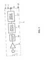
- FIG. 1shows a preferred embodiment of a digital microphone according to the invention.
- the digital microphonecomprises a housing or casing 2 with a sound inlet port 3.
- An electret transducer element 1is electrically coupled to an integrated circuit and both arranged inside the housing 2.
- the integrated circuitcomprises preamplifier 20, high pass filter 30, analog multilevel converter 40 and a digital signal converter 50.
- the integrated circuitis mounted on, and supported by, a ceramic substrate carrier (not shown) while electrical connectivity between devices is established by wire-bonding techniques that are well-known in the art.
- the present embodiment of the inventionis implemented as a sub-miniature electret microphone capable of operating on supply voltages down to 1.0 Volt and with a typical power consumption of about 100 - 200 ⁇ W.
- the present embodimentis therefore particularly well adapted for hearing instrument applications where low-voltage and low-power requirements are essential to conserve battery power.
- the digital microphoneadditionally comprises a set of externally accessible terminals in form of an output signal terminal 60, a clock input terminal 61, a power supply terminal 62 and a ground terminal 59.
- the clock input terminal 61is adapted for receipt of an externally generated clock signal which controls timing and clock rate of the single-bit output signal on output signal terminal 60 to provide a simple and synchronous interface between the digital microphone and the external processor.
- the single-bit output signalmay be transmitted asynchronously or synchronously to the external processor through a single data line.
- the processormust include appropriate data receipt and clock retrieval means.
- the single-bit output signal or output datamay advantageously comprise an embedded or coded clock signal such as a Manchester coded composite clock/data line wherein the embedded clock signal is derived from an integral clock generator means disposed on the integrated circuit.
- the electret transducer element 1comprises a displaceable diaphragm adapted to receive an acoustical signal through the sound inlet 3 and generate a transducer signal representative of the acoustical signal.
- the transducer signalis conveyed to a low-power and low-noise CMOS based preamplifier 20 adapted to amplify and buffer the transducer signal and provide an amplified transducer signal to the analog multilevel converter 40 or sigma-delta (SD) modulator, which comprises a multilevel-quantizer so as to convert the amplified transducer signal into a multi-bit samples representative of the transducer signal.
- SDSigma-delta
- the multi-level quantizercomprises three discrete levels represented as +1, 0 and -1.
- Other embodimentsmay comprise a larger number of discrete quantization levels such as 5 levels or 8 levels or 16 - 64 levels depending on factors such as performance, tolerable complexity and size of the integrated circuit itself.
- the multi-bit samples provided by SD modulator 40are operatively coupled to the digital signal converter 50 adapted to convert the multi-level digital signal into a single-bit output signal.
- the single-bit output signalis made accessible to an external programmable processor such as a signal processor or microprocessor through an externally accessible terminal 60 placed on the ceramic hybrid substrate and electrically connected to a corresponding terminal of the integrated circuit.
- the integrated circuit of the present embodiment of the inventionis preferably manufactured by 0.35 ⁇ m CMOS that provides low-noise and high performance analog PMOS transistors for application in the preamplifier 20 combined with high-density and low power digital logic circuitry for application in the digital logic circuitry of digital signal converter 50.
- CMOS processeshaving larger or smaller feature sizes as well as BiCMOS process could alternatively be utilized.
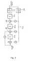
- FIG. 2is a detailed block diagram of a first embodiment of the digital signal converter 50 illustrating individual parts or components of the converter 50 in more detail.
- the digital signal converter 50is compatible with an analog multilevel converter or delta-sigma multi-level quantizer in which multi-bit samples are represented in a conventional two's complement format.
- a forward signal pathcomprises three cascaded discrete two's complement integrators 51 a, 51 b, 51 c located in front of single-bit quantizer or comparator 55 that quantizes incoming 16 bit digital signal samples into a bi-level, or single-bit, output signal.
- the input signal to the converter 50is a 2 bit signal provided in two's complement format.
- a feedback loopextends around the forward signal path and comprises a single-bit decision circuit or comparator 56 that feeds a MSB value, or sign, of the single-bit output signal back to three separate feedback loops with respective feedback coefficients, a 0 , a 1 , a 2 , These three separate feedback loops feed respective feedback signals into respective summing junctions or 16 bit adders 52-54 to provide error or noise shaping in the digital signal converter 50.
- the noise shapingoperates to move or transpose low-frequency noise components, introduced as a result of signal quantization of the multi-bit input signal, to a high-frequency range above audibility.
- a feed-forward loop with a predetermined feed-forward coefficient, b 0 , around the first adder 51may as illustrated optionally be added to the digital signal converter 50 to improve its dynamic range and stability.
- Internal state variables or signals e.g. at summing nodes 52-54are preferably represented by respective 16 bit two's complement numbers.
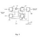
- Figure 3illustrates another embodiment of the digital signal converter 50 based on direct symbol mapping.
- This implementation of the digital signal converter 50requires a minimum of logic circuitry and therefore represents a very attractive option for low-power and/or low cost applications like hearing instruments and mobile phones.
- the operationis based on a novel coding of the two bit samples ⁇ D0, D1 ⁇ provided in standard two's complement format by the tri-level sigma-delta (SD) modulator 40 ( Fig. 1 ).
- SDtri-level sigma-delta
- quantization level +1is coded as symbol ⁇ 11 ⁇ , while level 0 is represented by symbol ⁇ 01 ⁇ , and level -1 is finally represented by symbol ⁇ 00 ⁇ . Accordingly, a symbol associated with a particular quantization level directly represents the average signal value of that quantization level by the coding mechanism of the digital signal converter 50.
- This coding formmakes it possible to generate the single-bit output signal in a very efficient manner by a collection of four D-type Flip Flops 21, 22, 25 and 26, a dual-input multiplexer 26 and XOR gate 27.
- D-FF 25is operative to halve a clock frequency provided on the clock input 25a wherein the clock frequency signal may have been derived from the external clock signal terminal 61 ( Fig. 1 ).
- D-type FFs 21 and 22operates on half the clock frequency of D-type FF 26 that generates the single bit output signal or bit-stream and the Nyquist criterion is exactly complied with by direct coding and conversion of incoming multi-bit samples.
- a different coding of the symbols or multi-bit samplesis possible within the general inventive concept such as representing level +1 by symbol ⁇ 1111 ⁇ or ⁇ 111111 ⁇ and the other quantization levels in a corresponding manner.
- the symbols that represent +1 and -1can both be inverted and/or the 0 level coded "01 ⁇ or "10 ⁇ .
- several efficient coding formats of quantization levels provided by a five-level SD modulatoralso exist, e.g. by using a collection symbols that each comprises four bits to represent the corresponding quantization level, such as below-mentioned exemplary format:
- FIG. 4is a detailed block diagram of the analog multi-level SD modulator 40 or SD modulator illustrating individual components of the modulator 40.
- the amplified transducer signalis provided as an analog input signal to the SD modulator, which converts received input signals into a multi-bit samples output representative of the transducer signal.
- a cascade of three integrators, 41a-41cis located in a forward signal path of the SD modulator 40.
- An output of a last integrator 41 cis operatively coupled to a three-level quantizer 45 that quantizes amplitude values of a continuous-time signal at the output of integrator 41 b into a dual-bit digital signal samples in two's complement format.
- a feedback loop around the SD modulatorcomprises a multilevel digital-to-analog converter 46 that feeds a value of the multi-bit samples output signal back to three separate feedback loops with respective feedback coefficients, a 0 , a 1 and a 2 .
- These three separate feedback loopsfeed respective feedback signals into respective summing junctions 42 - 44 to provide error shaping in the SD modulator 40 and transpose or push a substantial portion of quantization noise generated by the three-level quantizer 45 to a frequency range above audibility, i.e. above about 16 or 20 kHz.
- An optional feed-forward loop with a predetermined feed-forward coefficient, b 0around the first integrator 41 a has been added to the SD modulator 40 as illustrated to improve its dynamic range and stability.
- the present SD modulator 40is preferably operated with a sampling clock frequency of 1.024 MHz while the digital signal converter 50 is operated with a 2.048 MHz output data rate of the single-bit output signal.
- an interpolatoris inserted between the SD modulator 40 and the digital signal converter 50, in accordance with Fig. 2 , to raise the sampling rate of the multi-bit samples provided by the SD modulator to a target rate of 2.048 MHz required by the digital signal converter 50.
- sample rate conversion meansmay comprise a cascade of a decimator 65 and an interpolator 66. Inclusion of appropriate sample rate conversion means may be advantageous in some embodiments of the invention to interface a certain sample rate of signals from the SD modulator 40 to a standardized data output rate required by the digital signal converter 50.
Landscapes
- Engineering & Computer Science (AREA)
- Physics & Mathematics (AREA)
- Acoustics & Sound (AREA)
- Signal Processing (AREA)
- Theoretical Computer Science (AREA)
- Compression, Expansion, Code Conversion, And Decoders (AREA)
Abstract
Description
- The invention relates to a digital microphone comprising an integral analog-to-digital converter based on a multi-level quantizer in cascade with a digital signal converter which is adapted to provide a single-bit output signal. Digital microphones in accordance with the invention are particulary well adapted for use in mobile terminals and compact portable communication equipment such as mobile or cellular phones, headsets, hearing prostheses etc.
- Microphones with integral analag-to-digital converters, or digital microphones, are known in the art.
EP 1 052880 ,WO 021062101 US 5,769,848 andGB 2319922 WO 02/062101 US 6,326,912 discloses an analog-to-digital converter comprising a front-end multi-bit delta-sigma modulator coupled directly, or indirectly, to a back-end single-bit delta-sigma modulator for professional audio applications such as Super Audio Compact Discs that are based on a bit stream format or DVD Audio Discs that are based on a 24-bit PCM format.- While single-bit sigma-delta modulators have been successfully incorporated in a commercially available miniature microphone for hearing aid applications, there is a need for digital microphones employing integral analog-to-digital converters of improved performance. The improved digital microphones could advantageously be backward compatible with existing single-bit output devices. Improved performance analog-to-digital converters can be obtained by replacing conventional single-bit, or dual-level, quantizers with a multi-level quantizer in sigma-delta converter architectures.
- The invention relates to a digital microphone comprising:
- a microphone housing having a sound inlet and comprising:
- a transducer element comprising a displaceable diaphragm and adapted to generate a transducer signal representative of sound received through the sound inlet,
- an analog-to-digital converter comprising a multi-level quantizer operatively coupled to the transducer means to convert the transducer signal into multi-bit samples representative of the transducer signal, the multi-level quantizer comprising between 3 and 64 quantization levels, wherein the multi-bit samples generated by the multi-level quantizer are represented by a set of corresponding symbols wherein each symbol comprises a number of one signs proportional with the magnitude of the corresponding multi-bit sample,
- a digital signal converter adapted to convert the multi-bit samples into a single-bit output signal, and
- an externally accessible terminal adapted to provide the single-bit output signal.
- In the present description and claims, the term "multi-level quantizer" designates a signal quantizer that comprises more than 2 quantization levels such as 3 or 5 or 7 discrete quantization levels.
- A significant advantage of the invention provided by the multilevel quantizer operatively coupled to the digital signal converter which converts the multibit samples into a single-bit output signal. The present invention therefore provides a digital microphone which benefits from the multi-level quantizer to provide a digitized version of the transducer signal of improved quality but still maintains a simple and versatile unformatted data output which previously have been a unique feature of analog-to-digital converters based on single bit quantizers. By virtue of the unformatted single-bit output signal, microprocessors or signal processors are readily interfaced to digital microphones in accordance with the present invention without any need to contain dedicated audio data interface circuitry compatible with several digital audio data protocols.
- Finally, designers of products that incorporate digital microphones in accordance with the invention enjoy a considerable flexibility in choosing an optimum performance versus complexity trade-oft in for example decimation filter design.
- The multilevel quantizer comprises between 3 and 64 quantization levels such as between 5 and 16 quantization levels to provide multi-bit samples representative thereof. The quantization levels may be selected so as to provide linear or equidistant amplitude spacing, or logarithmic amplitude spacing, or any other desired amplitude spacing The multi-level quantizer provides several benefits in comparison with a single bit quantizer. These improvements include, but are not limited to, lower power consumption for a given signal/noise ratio, improved signal/noise ratio for a given sampling frequency and improved suppression of annoying tonal noise components in the multi-bit samples or quantized signal.
- For a desired or target signal-to-noise ratio or dynamic range of the quantized signal, it is possible to reduce a clock frequency driving the analog-to-digital converter. This latter advantage is particularly beneficial when the digital microphone comprises an external input dock terminal for receipt of an externally generated clock signal such as a clock signal generated by an associated microprocessor or digital signal processor. In this latter embodiment of the invention, power losses associated with driving external parasitic capacitances on a clock line are reduced proportionally with the frequency of the externally generated clock signal.
- Preferably the digital microphone comprises a pre-amplifier inserted between the transducer element and the analog-to-digital converter. The input capacitance of the pre-amplifier may advantageously be selected or designed to be suitable for coupling the pre-amplifier input to a miniature transducer element, said input capacitance being smaller than 10 pF or smaller than 5 pF or 2 pF or 1 pF, or even more preferably less than 0 5 pF. This latter range of input capacitance values will optimize coupling of the pre-amplifier to miniature electret or condenser based transducer elements as commonly used in miniature microphones for hearing aid or mobile terminal applications.
- A DC blocking filter, such as a band pass or high pass filter may advantageously be operatively coupled 10 a preamplifier output providing an amplified transducer signal so as to prevent DC bias point fluctuations and/or low frequency signals at the preamplifier output are conveyed to the analog-to-digital converter.
- The digital microphone may comprise a dynamic transducer element or condenser transducer element. The dynamic transducer element may comprise a diaphragm with an attached voice coil suspended in a permanent magnetic field. The condenser transducer element may comprise a pair of closely spaced and suitably biased plates, such as a polymer diaphragm having an electrically conductive layer disposed thereon and an adjacently positioned perforated backplate.
- Alternatively, the transducer means may be formed in a semiconductor substrate such as silicon or any other suitable material using Micro Electro Mechanical Systems (MEMS) technologies. In the above-mentioned embodiments of the invention, the preamplifier, the analog-to-digital converter, the digital signal converter and, optionally, clock generating means may advantageously be formed on a common integrated circuit substrate. The preamplifier may be electrically coupled to the transducer means or element by utilization of flip-chip or wire-bonding techniques.
- The analog-to-digital converter preferably comprises an oversampled delta-sigma modulator adapted to sample the transducer signal or preamplifier signal with a clock signal frequency between 64 kHz and 512 kHz. For a desired or target audio bandwidth of 8 kHz, this clock signal frequency span corresponds to oversampling ratios of 4 and 32, respectively.
- According to one embodiment of the invention, the digital microphone comprises an integral clock generator adapted to generate a clock signal which is operatively coupled to the analog-to-digital converter to provide a sampling clock for the multi-level quantizer. An advantageous feature of this embodiment is a possibility to provide a digital microphone with no requirement for an externally accessible clock input terminal. The sampling clock signal of the analog-to-digital converter and, optionally, internal logic circuitry may be operated in by the internally generated clock signal or clock signal derived there from.
- Alternatively, the housing of the digital microphone may comprise a second externally accessible terminal for receipt of an external clock signal. The external clock signal is operatively coupled to the analog-to-digital converter to directly or indirectly control the sampling of the transducer signal. In an advantageous version of this latter embodiment of the digital microphone, the external clock signal is operatively coupled to DC voltage generating means disposed within the microphone housing and used to derive power for an internal DC supply voltage. The internal DC supply voltage may power at least the analog-to-digital converter and, optionally, all circuitry within the digital microphone such as a preamplifier, interpolation and decimation filters. This latter embodiment of the invention is therefore operative without a separate power supply terminal or pad on the microphone housing. The lack of the separate power supply terminal is particularly advantageous for miniature low-power digital microphones such as digital hearing aid microphones that may have a nominal current consumption of less than 250 µA or less than 150 µA at 1.0 Volt supply voltage. In a preferred embodiment of the invention, the digital microphone is adapted to operate on a supply voltage lower than 2.9 V or lower than 1.8 Volt such as lower than 1.5 Volt or lower than 1.2 Volt.
- According to a preferred embodiment of the invention, interpolation means or an interpolator is inserted between the analog-to-digital converter and the digital signal converter to interface between different sample rates of the multi-bit samples and the single-bit output signal. The interpolator may advantageously comprise a low pass filter and be adapted to raise the sample rate with a factor of 2 - 32.
- The multi-bit samples provided by the analog-to-digital converter may be represented by a two's complement data format and conveyed to an interpolator or decimator in that format. In contrast, in accordance with a particularly advantageous embodiment of the invention, the multi-bit samples provided by the analog-to-digital converter are represented by a set of corresponding symbols wherein each symbol comprises a number of one signs proportional with a magnitude of the corresponding multi-bit sample. This symbol representation is particularly advantageous in connection with three and five level modulators since an efficient and direct mapping between multi-bit samples and the single bit output is possible, but generally a multi-level quantizer comprising N discrete quantization levels may utilize corresponding symbols that comprises N-1 bits to represent each of the N levels with a unique symbol.
- According to a second aspect of the invention, a portable communication device comprises a digital microphone according to the present invention. The portable communication device may be powered by disposable or rechargeable batteries and optimized for low-power operation. The portable communication device may comprise a mobile terminal, a cellular phone, a headset, a hearing prosthesis or instrument etc.
- According to an aspect of the invention, a monolithic integrated circuit of the microphone comprises a preamplifier adapted to provide an amplified transducer signal and comprising an input section couplable to a miniature electret or condenser transducer element and an analog-to-digital converter comprising a multi-level-quantizer operatively coupled to the amplified transducer signal and adapted to convert the amplified transducer signal into multi-bit samples representative of the amplified transducer signal and a digital signal converter adapted to convert the multi-bit samples into a single-bit output signal. An integrated circuit pad is finally adapted to provide the single-bit output signal.
- The monolithic integrated circuit may be fabricated in a standard CMOS process such as 0.5 µm or 0.35 µm CMOS. The input impedance of the preamplifier of the monolithic circuit is preferably substantially capacitive and corresponding to a capacitance less than 2 pF, or less than 1 pF, or even more preferably less than 0.5 pF to support interfacing or coupling 10 a miniature electret element without introducing unacceptable signal losses by source loading effects.
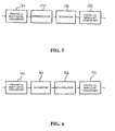
FIG. 1 is a block diagram of a digital microphone assembly according to a preferred embodiment of the present invention,FIG. 2 is a block diagram of a first digital signal converter for use in the digital microphone assembly illustrated inFIG. 1 ,FIG 3 is a block diagram of a second alternative digital signal converter for use in the digital microphone assembly illustrated inFig. 1 ,FIG. 4 is a block diagram of a three-level sigma-delta based AD converter,FIG. 5 is a block diagram of a first interface processing circuitry between the three-level sigma-delta based AD converter and the digital signal converter,- Fig 8 is a block diagram of a second interface processing circuitry between the three-level sigma-delta based AD converter and the digital signal converter.
Figure 1 shows a preferred embodiment of a digital microphone according to the invention. The digital microphone comprises a housing orcasing 2 with a sound inlet port 3. An electret transducer element 1 is electrically coupled to an integrated circuit and both arranged inside thehousing 2. The integrated circuit comprisespreamplifier 20,high pass filter 30, analogmultilevel converter 40 and adigital signal converter 50. The integrated circuit is mounted on, and supported by, a ceramic substrate carrier (not shown) while electrical connectivity between devices is established by wire-bonding techniques that are well-known in the art.- The present embodiment of the invention is implemented as a sub-miniature electret microphone capable of operating on supply voltages down to 1.0 Volt and with a typical power consumption of about 100 - 200 µW. The present embodiment is therefore particularly well adapted for hearing instrument applications where low-voltage and low-power requirements are essential to conserve battery power. The digital microphone additionally comprises a set of externally accessible terminals in form of an
output signal terminal 60, aclock input terminal 61, apower supply terminal 62 and aground terminal 59. Theclock input terminal 61 is adapted for receipt of an externally generated clock signal which controls timing and clock rate of the single-bit output signal onoutput signal terminal 60 to provide a simple and synchronous interface between the digital microphone and the external processor. - Alternatively, in respect of applications wherein a key concern is to minimize the number of external terminals, the single-bit output signal may be transmitted asynchronously or synchronously to the external processor through a single data line. The processor must include appropriate data receipt and clock retrieval means. In an embodiment of the invention wherein the single-bit output signal is transmitted synchronously to the external processor through a single data line, the single-bit output signal or output data may advantageously comprise an embedded or coded clock signal such as a Manchester coded composite clock/data line wherein the embedded clock signal is derived from an integral clock generator means disposed on the integrated circuit.
- The electret transducer element 1 comprises a displaceable diaphragm adapted to receive an acoustical signal through the sound inlet 3 and generate a transducer signal representative of the acoustical signal. The transducer signal is conveyed to a low-power and low-noise CMOS based
preamplifier 20 adapted to amplify and buffer the transducer signal and provide an amplified transducer signal to the analogmultilevel converter 40 or sigma-delta (SD) modulator, which comprises a multilevel-quantizer so as to convert the amplified transducer signal into a multi-bit samples representative of the transducer signal. According to the present embodiment of the invention, the multi-level quantizer comprises three discrete levels represented as +1, 0 and -1. Other embodiments may comprise a larger number of discrete quantization levels such as 5 levels or 8 levels or 16 - 64 levels depending on factors such as performance, tolerable complexity and size of the integrated circuit itself. - The multi-bit samples provided by
SD modulator 40 are operatively coupled to thedigital signal converter 50 adapted to convert the multi-level digital signal into a single-bit output signal. Finally, the single-bit output signal is made accessible to an external programmable processor such as a signal processor or microprocessor through an externallyaccessible terminal 60 placed on the ceramic hybrid substrate and electrically connected to a corresponding terminal of the integrated circuit. The integrated circuit of the present embodiment of the invention is preferably manufactured by 0.35 µm CMOS that provides low-noise and high performance analog PMOS transistors for application in thepreamplifier 20 combined with high-density and low power digital logic circuitry for application in the digital logic circuitry ofdigital signal converter 50. However, other CMOS processes having larger or smaller feature sizes as well as BiCMOS process could alternatively be utilized. Figure 2 is a detailed block diagram of a first embodiment of thedigital signal converter 50 illustrating individual parts or components of theconverter 50 in more detail. Thedigital signal converter 50 is compatible with an analog multilevel converter or delta-sigma multi-level quantizer in which multi-bit samples are represented in a conventional two's complement format.- A forward signal path comprises three cascaded discrete two's
complement integrators 51 a, 51 b, 51 c located in front of single-bit quantizer orcomparator 55 that quantizes incoming 16 bit digital signal samples into a bi-level, or single-bit, output signal. The input signal to theconverter 50 is a 2 bit signal provided in two's complement format. A feedback loop extends around the forward signal path and comprises a single-bit decision circuit orcomparator 56 that feeds a MSB value, or sign, of the single-bit output signal back to three separate feedback loops with respective feedback coefficients, a0, a1, a2, These three separate feedback loops feed respective feedback signals into respective summing junctions or 16 bit adders 52-54 to provide error or noise shaping in thedigital signal converter 50. The noise shaping operates to move or transpose low-frequency noise components, introduced as a result of signal quantization of the multi-bit input signal, to a high-frequency range above audibility. A feed-forward loop with a predetermined feed-forward coefficient, b0, around the first adder 51 may as illustrated optionally be added to thedigital signal converter 50 to improve its dynamic range and stability. Internal state variables or signals e.g. at summing nodes 52-54 are preferably represented by respective 16 bit two's complement numbers. Figure 3 illustrates another embodiment of thedigital signal converter 50 based on direct symbol mapping. This implementation of thedigital signal converter 50 requires a minimum of logic circuitry and therefore represents a very attractive option for low-power and/or low cost applications like hearing instruments and mobile phones. The operation is based on a novel coding of the two bit samples {D0, D1} provided in standard two's complement format by the tri-level sigma-delta (SD) modulator 40 (Fig. 1 ).- In the present embodiment, quantization level +1 is coded as symbol {11}, while level 0 is represented by symbol {01}, and level -1 is finally represented by symbol {00}. Accordingly, a symbol associated with a particular quantization level directly represents the average signal value of that quantization level by the coding mechanism of the
digital signal converter 50. This coding form makes it possible to generate the single-bit output signal in a very efficient manner by a collection of four D-type Flip Flops 21, 22, 25 and 26, a dual-input multiplexer 26 andXOR gate 27. D-FF 25 is operative to halve a clock frequency provided on the clock input 25a wherein the clock frequency signal may have been derived from the external clock signal terminal 61 (Fig. 1 ). D-type FFs type FF 26 that generates the single bit output signal or bit-stream and the Nyquist criterion is exactly complied with by direct coding and conversion of incoming multi-bit samples. - Clearly, a different coding of the symbols or multi-bit samples is possible within the general inventive concept such as representing level +1 by symbol {1111} or {111111} and the other quantization levels in a corresponding manner. Likewise, the symbols that represent +1 and -1 can both be inverted and/or the 0 level coded "01} or "10}. Likewise, several efficient coding formats of quantization levels provided by a five-level SD modulator also exist, e.g. by using a collection symbols that each comprises four bits to represent the corresponding quantization level, such as below-mentioned exemplary format:
Level + 2 is represented by symbol {1111},- Level +1 is represented by symbol {1110},
- Level 0 is represented by symbol {1010},
- Level -1 is represented by symbol {0001},
- Level -2 is represented by symbol {0000}.
Figure 4 is a detailed block diagram of the analogmulti-level SD modulator 40 or SD modulator illustrating individual components of themodulator 40. The amplified transducer signal is provided as an analog input signal to the SD modulator, which converts received input signals into a multi-bit samples output representative of the transducer signal. A cascade of three integrators, 41a-41c is located in a forward signal path of theSD modulator 40. An output of a last integrator 41 c is operatively coupled to a three-level quantizer 45 that quantizes amplitude values of a continuous-time signal at the output of integrator 41 b into a dual-bit digital signal samples in two's complement format. A feedback loop around the SD modulator comprises a multilevel digital-to-analog converter 46 that feeds a value of the multi-bit samples output signal back to three separate feedback loops with respective feedback coefficients, a0, a1 and a2. These three separate feedback loops feed respective feedback signals into respective summing junctions 42 - 44 to provide error shaping in theSD modulator 40 and transpose or push a substantial portion of quantization noise generated by the three-level quantizer 45 to a frequency range above audibility, i.e. above about 16 or 20 kHz. An optional feed-forward loop with a predetermined feed-forward coefficient, b0, around thefirst integrator 41 a has been added to theSD modulator 40 as illustrated to improve its dynamic range and stability.- The
present SD modulator 40 is preferably operated with a sampling clock frequency of 1.024 MHz while thedigital signal converter 50 is operated with a 2.048 MHz output data rate of the single-bit output signal. In the present embodiment of the invention, an interpolator is inserted between theSD modulator 40 and thedigital signal converter 50, in accordance withFig. 2 , to raise the sampling rate of the multi-bit samples provided by the SD modulator to a target rate of 2.048 MHz required by thedigital signal converter 50. - As illustrated in
Figure 5 and Figure 6 various types of sample rate conversion may be provided in-between theSD modulator 40 and thedigital signal converter 50. According toFigure 5 , aninterpolator 55 anddecimator 56 may be cascaded to provide flexible sample rate conversion between the sample rate of signals provided by theSD modulator 40 and the sample rate of the output signal ofdigital signal converter 50 wherein a ratio between the sample rates may be an integer or fractional number such as 4, 8, 16, 32 or 1.5 or 32/44.1 or 16/44.1 etc. According toFigure 6 , the sample rate conversion means may comprise a cascade of adecimator 65 and aninterpolator 66. Inclusion of appropriate sample rate conversion means may be advantageous in some embodiments of the invention to interface a certain sample rate of signals from theSD modulator 40 to a standardized data output rate required by thedigital signal converter 50.
Claims (15)
- A digital microphone comprising:a microphone housing having a sound inlet and comprising:- a transducer element comprising a displaceable diaphragm and adapted to generate a transducer signal representative of sound received through the sound inlet,- an analog-to-digital converter comprising a multi-level quantizer operatively coupled to the transducer means to convert the transducer signal into multi-bit samples representative of the transducer signal, the multi-level quantizer comprising between 3 and 64 quantization levels, wherein the multi-bit samples generated by the multi-level quantizer are represented by a set of corresponding symbols wherein each symbol comprises a number of one signs proportional with the magnitude of the corresponding multi-bit sample,- a digital signal converter adapted to convert the multi-bit samples into a single-bit output signal, and- an externally accessible terminal adapted to provide the single-bit output signal.
- A digital microphone according to claim 1, wherein the digital signal converter is a sigma-delta signal converter.
- A digital microphone according to claim 1 or 2, wherein the analog-to-digital converter (40) comprises an oversampled delta-sigma modulator.
- A digital microphone according to any of claims 1-3, comprising an integral clock generator operatively coupled to the analog-to-digital converter (40) and the digital signal converter (50).
- A digital microphone according to any of claims 1-4, wherein the microphone housing (2) comprises a second externally accessible terminal (61) for receipt of an external clock signal.
- A digital microphone according to claim 5, comprising DC voltage generating means disposed within the microphone housing (2) and operatively coupled to the external clock signal so as to derive a DC voltage supply for operating at least the analog-to-digital converter (40).
- A digital microphone according to any of the preceding claims, such that the multi-bit samples provided by the analog-to-digital converter (40) are represented in two's complement format.
- A digital microphone according to claim 1, wherein the multi-level quantizer (45) comprises 3 or 5 discrete quantization levels.
- A digital microphone according to claim 1, wherein the multi-level quantizer (45) comprises N discrete quantization levels and each corresponding symbol comprises N-1 bits; N being an integer between 3 and 17.
- A digital microphone according to any of claims 1-9, wherein the digital signal converter (50) comprises a delay circuit in cascade with an integer ratio upsampler.
- A digital microphone according to any of the preceding claims, comprising an interpolator (55) operatively coupled between the multi-bit samples provided by the analog-to-digital converter (40) and the digital signal converter (50).
- A digital microphone according to claim 1, wherein the analog-to-digital converter (40) comprises an oversampled delta-sigma modulator.
- A portable communication device comprising a digital microphone according to any of the preceding claims.
- A digital microphone according to any of the preceding claims, comprising a monolithic integrated circuit, the circuit comprising- a preamplifier adapted to provide an amplified transducer signal and comprising an input section coupled to a miniature electret or condenser transducer element,- the analog-to-digital converter comprising a multilevel-quantizer operatively coupled to the amplified transducer signal,- the digital signal converter, and- the terminal pad adapted to provide the single-bit output signal.
- The digital microphone according to claim 14, wherein the multi-level quantizer (45) of the analog-to-digital converter (40) comprises 3 or 5 discrete quantization levels.
Applications Claiming Priority (2)
| Application Number | Priority Date | Filing Date | Title |
|---|---|---|---|
| US52503903P | 2003-11-24 | 2003-11-24 | |
| PCT/DK2004/000680WO2005009072A2 (en) | 2003-11-24 | 2004-10-08 | Microphone comprising integral multi-level quantizer and single-bit conversion means |
Publications (2)
| Publication Number | Publication Date |
|---|---|
| EP1690437A2 EP1690437A2 (en) | 2006-08-16 |
| EP1690437B1true EP1690437B1 (en) | 2011-01-12 |
Family
ID=34079506
Family Applications (1)
| Application Number | Title | Priority Date | Filing Date |
|---|---|---|---|
| EP04762899AExpired - LifetimeEP1690437B1 (en) | 2003-11-24 | 2004-10-08 | Microphone comprising integral multi-level quantizer and single-bit conversion means |
Country Status (6)
| Country | Link |
|---|---|
| US (1) | US7630504B2 (en) |
| EP (1) | EP1690437B1 (en) |
| CN (1) | CN1879446B (en) |
| AT (1) | ATE495625T1 (en) |
| DE (1) | DE602004031044D1 (en) |
| WO (1) | WO2005009072A2 (en) |
Cited By (1)
| Publication number | Priority date | Publication date | Assignee | Title |
|---|---|---|---|---|
| WO2014023363A1 (en)* | 2012-08-10 | 2014-02-13 | Epcos Ag | Mems microphone and method of operating the mems microphone |
Families Citing this family (53)
| Publication number | Priority date | Publication date | Assignee | Title |
|---|---|---|---|---|
| EP1690437B1 (en)* | 2003-11-24 | 2011-01-12 | Epcos Pte Ltd | Microphone comprising integral multi-level quantizer and single-bit conversion means |
| US8041066B2 (en) | 2007-01-03 | 2011-10-18 | Starkey Laboratories, Inc. | Wireless system for hearing communication devices providing wireless stereo reception modes |
| US9774961B2 (en) | 2005-06-05 | 2017-09-26 | Starkey Laboratories, Inc. | Hearing assistance device ear-to-ear communication using an intermediate device |
| CN101288337B (en) | 2005-07-19 | 2012-11-21 | 美国亚德诺半导体公司 | Programmable microphone |
| DE202006002942U1 (en)* | 2006-02-22 | 2007-07-05 | Brauner, Dirk | Adapter for microphones |
| GB2437772B8 (en)* | 2006-04-12 | 2008-09-17 | Wolfson Microelectronics Plc | Digital circuit arrangements for ambient noise-reduction. |
| WO2007144808A2 (en)* | 2006-06-15 | 2007-12-21 | Nxp B.V. | A method of providing a clock frequency for a processor |
| US8208642B2 (en) | 2006-07-10 | 2012-06-26 | Starkey Laboratories, Inc. | Method and apparatus for a binaural hearing assistance system using monaural audio signals |
| US8542850B2 (en)* | 2007-09-12 | 2013-09-24 | Epcos Pte Ltd | Miniature microphone assembly with hydrophobic surface coating |
| DE102007058951B4 (en)* | 2007-12-07 | 2020-03-26 | Snaptrack, Inc. | MEMS package |
| US7889108B2 (en)* | 2008-05-09 | 2011-02-15 | Asahi Kasei Microdevices Corporation | Hybrid delta-sigma ADC |
| US8411603B2 (en)* | 2008-06-19 | 2013-04-02 | Broadcom Corporation | Method and system for dual digital microphone processing in an audio CODEC |
| US8873769B2 (en)* | 2008-12-05 | 2014-10-28 | Invensense, Inc. | Wind noise detection method and system |
| KR101201198B1 (en)* | 2008-12-16 | 2012-11-15 | 한국전자통신연구원 | Apparatus and method for amplifying signal, and wireless transmitter therewith |
| US8345888B2 (en)* | 2009-04-28 | 2013-01-01 | Bose Corporation | Digital high frequency phase compensation |
| US8085946B2 (en)* | 2009-04-28 | 2011-12-27 | Bose Corporation | ANR analysis side-chain data support |
| US9083288B2 (en)* | 2009-06-11 | 2015-07-14 | Invensense, Inc. | High level capable audio amplification circuit |
| CN101924525B (en)* | 2009-06-11 | 2016-06-22 | 应美盛股份有限公司 | High performance voice frequency amplifying circuit |
| US8737653B2 (en) | 2009-12-30 | 2014-05-27 | Starkey Laboratories, Inc. | Noise reduction system for hearing assistance devices |
| DE102010006132B4 (en) | 2010-01-29 | 2013-05-08 | Epcos Ag | Miniaturized electrical component with a stack of a MEMS and an ASIC |
| US20130129117A1 (en)* | 2011-11-21 | 2013-05-23 | Henrik Thomsen | Audio amplification circuit |
| CN103138687B (en)* | 2011-11-22 | 2017-04-12 | 应美盛股份有限公司 | Distortion inhibition in high level audio frequency amplifying circuit |
| EP2608569B1 (en)* | 2011-12-22 | 2014-07-23 | ST-Ericsson SA | Digital microphone device with extended dynamic range |
| US9467774B2 (en) | 2012-02-10 | 2016-10-11 | Infineon Technologies Ag | System and method for a PCM interface for a capacitive signal source |
| US9374646B2 (en)* | 2012-08-31 | 2016-06-21 | Starkey Laboratories, Inc. | Binaural enhancement of tone language for hearing assistance devices |
| US20140301571A1 (en) | 2013-04-09 | 2014-10-09 | Cirrus Logic, Inc. | Systems and methods for generating a digital output signal in a digital microphone system |
| US9711166B2 (en)* | 2013-05-23 | 2017-07-18 | Knowles Electronics, Llc | Decimation synchronization in a microphone |
| US20180317019A1 (en) | 2013-05-23 | 2018-11-01 | Knowles Electronics, Llc | Acoustic activity detecting microphone |
| US10028054B2 (en)* | 2013-10-21 | 2018-07-17 | Knowles Electronics, Llc | Apparatus and method for frequency detection |
| US10020008B2 (en) | 2013-05-23 | 2018-07-10 | Knowles Electronics, Llc | Microphone and corresponding digital interface |
| US9712923B2 (en) | 2013-05-23 | 2017-07-18 | Knowles Electronics, Llc | VAD detection microphone and method of operating the same |
| CN104348484B (en)* | 2013-07-31 | 2018-08-21 | 钰太芯微电子科技(上海)有限公司 | A kind of more bit moduli converters of continuous time for digital microphone |
| US9502028B2 (en) | 2013-10-18 | 2016-11-22 | Knowles Electronics, Llc | Acoustic activity detection apparatus and method |
| US9147397B2 (en) | 2013-10-29 | 2015-09-29 | Knowles Electronics, Llc | VAD detection apparatus and method of operating the same |
| US10003379B2 (en) | 2014-05-06 | 2018-06-19 | Starkey Laboratories, Inc. | Wireless communication with probing bandwidth |
| US10812900B2 (en) | 2014-06-02 | 2020-10-20 | Invensense, Inc. | Smart sensor for always-on operation |
| US9626981B2 (en) | 2014-06-25 | 2017-04-18 | Cirrus Logic, Inc. | Systems and methods for compressing a digital signal |
| WO2016112113A1 (en) | 2015-01-07 | 2016-07-14 | Knowles Electronics, Llc | Utilizing digital microphones for low power keyword detection and noise suppression |
| US9830080B2 (en) | 2015-01-21 | 2017-11-28 | Knowles Electronics, Llc | Low power voice trigger for acoustic apparatus and method |
| US10121472B2 (en) | 2015-02-13 | 2018-11-06 | Knowles Electronics, Llc | Audio buffer catch-up apparatus and method with two microphones |
| CN104796145A (en)* | 2015-04-23 | 2015-07-22 | 西安电子科技大学 | High-precision and low-distortion digital-analog converter |
| US9478234B1 (en) | 2015-07-13 | 2016-10-25 | Knowles Electronics, Llc | Microphone apparatus and method with catch-up buffer |
| US9894437B2 (en)* | 2016-02-09 | 2018-02-13 | Knowles Electronics, Llc | Microphone assembly with pulse density modulated signal |
| US10281485B2 (en)* | 2016-07-29 | 2019-05-07 | Invensense, Inc. | Multi-path signal processing for microelectromechanical systems (MEMS) sensors |
| JP6787158B2 (en)* | 2017-01-31 | 2020-11-18 | 株式会社富士通ゼネラル | Motor control device |
| CN107221335B (en)* | 2017-05-27 | 2020-07-14 | 大连理工大学 | Digitization device and method for monitoring audio signal |
| US11108988B2 (en)* | 2017-07-03 | 2021-08-31 | Sony Semiconductor Solutions Corporation | Transmitter and transmission method and receiver and reception method |
| US10348326B2 (en)* | 2017-10-23 | 2019-07-09 | Infineon Technologies Ag | Digital silicon microphone with interpolation |
| US11646725B2 (en)* | 2017-10-28 | 2023-05-09 | Solos Technology Limited | Fractional time delay structures in digitally oversampled microphone systems, circuits, and methods |
| US11637546B2 (en) | 2018-12-14 | 2023-04-25 | Synaptics Incorporated | Pulse density modulation systems and methods |
| GB2607505A (en)* | 2020-02-20 | 2022-12-07 | Cirrus Logic Int Semiconductor Ltd | Audio system with digital microphone |
| US11683624B1 (en)* | 2020-05-12 | 2023-06-20 | Qualcomm Technologies, Inc. | Transducer with analog and digital modulators |
| US11139820B1 (en)* | 2020-07-17 | 2021-10-05 | Infineon Technologies Ag | Efficient digital gain implementation in digital microphones |
Family Cites Families (16)
| Publication number | Priority date | Publication date | Assignee | Title |
|---|---|---|---|---|
| US5051799A (en)* | 1989-02-17 | 1991-09-24 | Paul Jon D | Digital output transducer |
| DE69527790D1 (en)* | 1995-09-29 | 2002-09-19 | St Microelectronics Srl | Digital microphone device |
| DE19606261C2 (en)* | 1996-02-06 | 1998-04-09 | Stage Tec Entwicklungsgesellsc | Microphone with assigned amplifier |
| US5769848A (en) | 1996-05-14 | 1998-06-23 | Wattanasirichaigoon; Somkiat | Endoscopic instrument |
| GB2319922B (en) | 1996-11-27 | 2000-05-03 | Sony Uk Ltd | Microphone |
| US6198417B1 (en)* | 1998-01-29 | 2001-03-06 | Massachusetts Institute Of Technology | Pipelined oversampling A/D converter |
| US6449370B1 (en)* | 1998-02-16 | 2002-09-10 | Matsushita Electric Industrial Co., Ltd. | Digital electro-acoustic transducer |
| EP1052880A3 (en) | 1998-10-07 | 2001-10-24 | Knowles Electronics, LLC | Digital hearing aid microphone |
| US6326912B1 (en)* | 1999-09-24 | 2001-12-04 | Akm Semiconductor, Inc. | Analog-to-digital conversion using a multi-bit analog delta-sigma modulator combined with a one-bit digital delta-sigma modulator |
| US20020106091A1 (en) | 2001-02-02 | 2002-08-08 | Furst Claus Erdmann | Microphone unit with internal A/D converter |
| WO2003023970A2 (en)* | 2001-09-07 | 2003-03-20 | Microsemi Corporation | Serial data interface with reduced power consumption |
| GB2386280B (en)* | 2002-03-07 | 2005-09-14 | Zarlink Semiconductor Inc | Digital microphone |
| WO2003088709A1 (en)* | 2002-04-10 | 2003-10-23 | Sonion A/S | Microphone assembly with auxiliary analog input |
| US7274716B2 (en)* | 2003-06-18 | 2007-09-25 | Texas Instruments Incorporated | Multiplexed sigma-delta interface |
| US6958717B1 (en)* | 2003-08-25 | 2005-10-25 | Analog Devices, Inc. | Method and apparatus for interconnecting analog and digital sections of A/D and D/A converters |
| EP1690437B1 (en)* | 2003-11-24 | 2011-01-12 | Epcos Pte Ltd | Microphone comprising integral multi-level quantizer and single-bit conversion means |
- 2004
- 2004-10-08EPEP04762899Apatent/EP1690437B1/ennot_activeExpired - Lifetime
- 2004-10-08WOPCT/DK2004/000680patent/WO2005009072A2/ennot_activeApplication Discontinuation
- 2004-10-08USUS10/580,505patent/US7630504B2/enactiveActive
- 2004-10-08ATAT04762899Tpatent/ATE495625T1/ennot_activeIP Right Cessation
- 2004-10-08DEDE602004031044Tpatent/DE602004031044D1/ennot_activeExpired - Lifetime
- 2004-10-08CNCN2004800332228Apatent/CN1879446B/ennot_activeExpired - Fee Related
Cited By (3)
| Publication number | Priority date | Publication date | Assignee | Title |
|---|---|---|---|---|
| WO2014023363A1 (en)* | 2012-08-10 | 2014-02-13 | Epcos Ag | Mems microphone and method of operating the mems microphone |
| JP2015530024A (en)* | 2012-08-10 | 2015-10-08 | エプコス アクチエンゲゼルシャフトEpcos Ag | MEMS microphone and method for driving MEMS microphone |
| US9673767B2 (en) | 2012-08-10 | 2017-06-06 | Tdk Corporation | MEMS microphone and method of operating the MEMS microphone |
Also Published As
| Publication number | Publication date |
|---|---|
| CN1879446B (en) | 2011-02-16 |
| WO2005009072A3 (en) | 2005-03-24 |
| WO2005009072A2 (en) | 2005-01-27 |
| ATE495625T1 (en) | 2011-01-15 |
| EP1690437A2 (en) | 2006-08-16 |
| US7630504B2 (en) | 2009-12-08 |
| CN1879446A (en) | 2006-12-13 |
| US20070127761A1 (en) | 2007-06-07 |
| DE602004031044D1 (en) | 2011-02-24 |
Similar Documents
| Publication | Publication Date | Title |
|---|---|---|
| EP1690437B1 (en) | Microphone comprising integral multi-level quantizer and single-bit conversion means | |
| EP1449404B1 (en) | A high efficiency driver for miniature loudspeakers | |
| TWI224935B (en) | Digital microphone | |
| CN112770226B (en) | Capacitive sensor assembly and semiconductor die | |
| US7619551B1 (en) | Audio codec, digital device and voice processing method | |
| EP1142127B1 (en) | Circuits, systems and methods for processing data in a one-bit format | |
| US9479865B2 (en) | Transducer amplification circuit | |
| EP3166330A1 (en) | Systems and methods for compressing a digital signal in a digital microphone system | |
| CN109698701B (en) | Digital silicon microphone with interpolation | |
| CN104969475B (en) | Digital-to-analog is converted | |
| US20070252736A1 (en) | Low power sigma delta modulator | |
| US6803869B1 (en) | Circuits, Systems, and methods for volume in low noise 1-bit digital audio systems | |
| CN114446311A (en) | Digital sound reconstruction method, system, device and medium | |
| US5886656A (en) | Digital microphone device | |
| KR20220066220A (en) | SDM encoder and related signal processing system | |
| CN110636407B (en) | All-digital loudspeaker system and working method thereof | |
| US7183954B1 (en) | Circuits, systems and methods for volume control in low noise 1-bit digital audio systems | |
| CN112929780B (en) | Audio chip and earphone of noise reduction processing |
Legal Events
| Date | Code | Title | Description |
|---|---|---|---|
| PUAI | Public reference made under article 153(3) epc to a published international application that has entered the european phase | Free format text:ORIGINAL CODE: 0009012 | |
| 17P | Request for examination filed | Effective date:20060626 | |
| AK | Designated contracting states | Kind code of ref document:A2 Designated state(s):AT BE BG CH CY CZ DE DK EE ES FI FR GB GR HU IE IT LI LU MC NL PL PT RO SE SI SK TR | |
| 17Q | First examination report despatched | Effective date:20061212 | |
| DAX | Request for extension of the european patent (deleted) | ||
| GRAP | Despatch of communication of intention to grant a patent | Free format text:ORIGINAL CODE: EPIDOSNIGR1 | |
| RIC1 | Information provided on ipc code assigned before grant | Ipc:H04M 3/04 20060101AFI20100706BHEP Ipc:H04R 1/04 20060101ALI20100706BHEP Ipc:H04R 3/00 20060101ALI20100706BHEP | |
| GRAS | Grant fee paid | Free format text:ORIGINAL CODE: EPIDOSNIGR3 | |
| GRAA | (expected) grant | Free format text:ORIGINAL CODE: 0009210 | |
| AK | Designated contracting states | Kind code of ref document:B1 Designated state(s):AT BE BG CH CY CZ DE DK EE ES FI FR GB GR HU IE IT LI LU MC NL PL PT RO SE SI SK TR | |
| REG | Reference to a national code | Ref country code:GB Ref legal event code:FG4D | |
| REG | Reference to a national code | Ref country code:CH Ref legal event code:EP | |
| REG | Reference to a national code | Ref country code:IE Ref legal event code:FG4D | |
| REF | Corresponds to: | Ref document number:602004031044 Country of ref document:DE Date of ref document:20110224 Kind code of ref document:P | |
| REG | Reference to a national code | Ref country code:DE Ref legal event code:R096 Ref document number:602004031044 Country of ref document:DE Effective date:20110224 | |
| REG | Reference to a national code | Ref country code:NL Ref legal event code:VDEP Effective date:20110112 | |
| PG25 | Lapsed in a contracting state [announced via postgrant information from national office to epo] | Ref country code:ES Free format text:LAPSE BECAUSE OF FAILURE TO SUBMIT A TRANSLATION OF THE DESCRIPTION OR TO PAY THE FEE WITHIN THE PRESCRIBED TIME-LIMIT Effective date:20110423 Ref country code:GR Free format text:LAPSE BECAUSE OF FAILURE TO SUBMIT A TRANSLATION OF THE DESCRIPTION OR TO PAY THE FEE WITHIN THE PRESCRIBED TIME-LIMIT Effective date:20110413 Ref country code:SE Free format text:LAPSE BECAUSE OF FAILURE TO SUBMIT A TRANSLATION OF THE DESCRIPTION OR TO PAY THE FEE WITHIN THE PRESCRIBED TIME-LIMIT Effective date:20110112 Ref country code:PT Free format text:LAPSE BECAUSE OF FAILURE TO SUBMIT A TRANSLATION OF THE DESCRIPTION OR TO PAY THE FEE WITHIN THE PRESCRIBED TIME-LIMIT Effective date:20110512 | |
| PG25 | Lapsed in a contracting state [announced via postgrant information from national office to epo] | Ref country code:CY Free format text:LAPSE BECAUSE OF FAILURE TO SUBMIT A TRANSLATION OF THE DESCRIPTION OR TO PAY THE FEE WITHIN THE PRESCRIBED TIME-LIMIT Effective date:20110112 Ref country code:PL Free format text:LAPSE BECAUSE OF FAILURE TO SUBMIT A TRANSLATION OF THE DESCRIPTION OR TO PAY THE FEE WITHIN THE PRESCRIBED TIME-LIMIT Effective date:20110112 Ref country code:FI Free format text:LAPSE BECAUSE OF FAILURE TO SUBMIT A TRANSLATION OF THE DESCRIPTION OR TO PAY THE FEE WITHIN THE PRESCRIBED TIME-LIMIT Effective date:20110112 Ref country code:BG Free format text:LAPSE BECAUSE OF FAILURE TO SUBMIT A TRANSLATION OF THE DESCRIPTION OR TO PAY THE FEE WITHIN THE PRESCRIBED TIME-LIMIT Effective date:20110412 Ref country code:NL Free format text:LAPSE BECAUSE OF FAILURE TO SUBMIT A TRANSLATION OF THE DESCRIPTION OR TO PAY THE FEE WITHIN THE PRESCRIBED TIME-LIMIT Effective date:20110112 Ref country code:AT Free format text:LAPSE BECAUSE OF FAILURE TO SUBMIT A TRANSLATION OF THE DESCRIPTION OR TO PAY THE FEE WITHIN THE PRESCRIBED TIME-LIMIT Effective date:20110112 Ref country code:SI Free format text:LAPSE BECAUSE OF FAILURE TO SUBMIT A TRANSLATION OF THE DESCRIPTION OR TO PAY THE FEE WITHIN THE PRESCRIBED TIME-LIMIT Effective date:20110112 Ref country code:BE Free format text:LAPSE BECAUSE OF FAILURE TO SUBMIT A TRANSLATION OF THE DESCRIPTION OR TO PAY THE FEE WITHIN THE PRESCRIBED TIME-LIMIT Effective date:20110112 | |
| PG25 | Lapsed in a contracting state [announced via postgrant information from national office to epo] | Ref country code:EE Free format text:LAPSE BECAUSE OF FAILURE TO SUBMIT A TRANSLATION OF THE DESCRIPTION OR TO PAY THE FEE WITHIN THE PRESCRIBED TIME-LIMIT Effective date:20110112 Ref country code:DK Free format text:LAPSE BECAUSE OF FAILURE TO SUBMIT A TRANSLATION OF THE DESCRIPTION OR TO PAY THE FEE WITHIN THE PRESCRIBED TIME-LIMIT Effective date:20110112 | |
| PLBE | No opposition filed within time limit | Free format text:ORIGINAL CODE: 0009261 | |
| STAA | Information on the status of an ep patent application or granted ep patent | Free format text:STATUS: NO OPPOSITION FILED WITHIN TIME LIMIT | |
| PG25 | Lapsed in a contracting state [announced via postgrant information from national office to epo] | Ref country code:RO Free format text:LAPSE BECAUSE OF FAILURE TO SUBMIT A TRANSLATION OF THE DESCRIPTION OR TO PAY THE FEE WITHIN THE PRESCRIBED TIME-LIMIT Effective date:20110112 Ref country code:CZ Free format text:LAPSE BECAUSE OF FAILURE TO SUBMIT A TRANSLATION OF THE DESCRIPTION OR TO PAY THE FEE WITHIN THE PRESCRIBED TIME-LIMIT Effective date:20110112 Ref country code:SK Free format text:LAPSE BECAUSE OF FAILURE TO SUBMIT A TRANSLATION OF THE DESCRIPTION OR TO PAY THE FEE WITHIN THE PRESCRIBED TIME-LIMIT Effective date:20110112 | |
| 26N | No opposition filed | Effective date:20111013 | |
| PG25 | Lapsed in a contracting state [announced via postgrant information from national office to epo] | Ref country code:IT Free format text:LAPSE BECAUSE OF FAILURE TO SUBMIT A TRANSLATION OF THE DESCRIPTION OR TO PAY THE FEE WITHIN THE PRESCRIBED TIME-LIMIT Effective date:20110112 | |
| REG | Reference to a national code | Ref country code:DE Ref legal event code:R097 Ref document number:602004031044 Country of ref document:DE Effective date:20111013 | |
| PG25 | Lapsed in a contracting state [announced via postgrant information from national office to epo] | Ref country code:MC Free format text:LAPSE BECAUSE OF NON-PAYMENT OF DUE FEES Effective date:20111031 | |
| REG | Reference to a national code | Ref country code:CH Ref legal event code:PL | |
| GBPC | Gb: european patent ceased through non-payment of renewal fee | Effective date:20111008 | |
| REG | Reference to a national code | Ref country code:FR Ref legal event code:ST Effective date:20120629 | |
| PG25 | Lapsed in a contracting state [announced via postgrant information from national office to epo] | Ref country code:LI Free format text:LAPSE BECAUSE OF NON-PAYMENT OF DUE FEES Effective date:20111031 Ref country code:CH Free format text:LAPSE BECAUSE OF NON-PAYMENT OF DUE FEES Effective date:20111031 | |
| REG | Reference to a national code | Ref country code:IE Ref legal event code:MM4A | |
| PG25 | Lapsed in a contracting state [announced via postgrant information from national office to epo] | Ref country code:FR Free format text:LAPSE BECAUSE OF NON-PAYMENT OF DUE FEES Effective date:20111102 Ref country code:GB Free format text:LAPSE BECAUSE OF NON-PAYMENT OF DUE FEES Effective date:20111008 | |
| PG25 | Lapsed in a contracting state [announced via postgrant information from national office to epo] | Ref country code:IE Free format text:LAPSE BECAUSE OF NON-PAYMENT OF DUE FEES Effective date:20111008 | |
| PG25 | Lapsed in a contracting state [announced via postgrant information from national office to epo] | Ref country code:LU Free format text:LAPSE BECAUSE OF NON-PAYMENT OF DUE FEES Effective date:20111008 | |
| PG25 | Lapsed in a contracting state [announced via postgrant information from national office to epo] | Ref country code:TR Free format text:LAPSE BECAUSE OF FAILURE TO SUBMIT A TRANSLATION OF THE DESCRIPTION OR TO PAY THE FEE WITHIN THE PRESCRIBED TIME-LIMIT Effective date:20110112 | |
| PG25 | Lapsed in a contracting state [announced via postgrant information from national office to epo] | Ref country code:HU Free format text:LAPSE BECAUSE OF FAILURE TO SUBMIT A TRANSLATION OF THE DESCRIPTION OR TO PAY THE FEE WITHIN THE PRESCRIBED TIME-LIMIT Effective date:20110112 | |
| REG | Reference to a national code | Ref country code:DE Ref legal event code:R082 Ref document number:602004031044 Country of ref document:DE Representative=s name:EPPING HERMANN FISCHER, PATENTANWALTSGESELLSCH, DE Ref country code:DE Ref legal event code:R081 Ref document number:602004031044 Country of ref document:DE Owner name:TDK CORP., JP Free format text:FORMER OWNER: EPCOS PTE LTD, SINGAPORE, SG Ref country code:DE Ref legal event code:R082 Ref document number:602004031044 Country of ref document:DE Representative=s name:EPPING HERMANN FISCHER PATENTANWALTSGESELLSCHA, DE | |
| P01 | Opt-out of the competence of the unified patent court (upc) registered | Effective date:20230706 | |
| PGFP | Annual fee paid to national office [announced via postgrant information from national office to epo] | Ref country code:DE Payment date:20230830 Year of fee payment:20 | |
| REG | Reference to a national code | Ref country code:DE Ref legal event code:R071 Ref document number:602004031044 Country of ref document:DE |