EP1689266B1 - Adjustable reclining chair - Google Patents
Adjustable reclining chairDownload PDFInfo
- Publication number
- EP1689266B1 EP1689266B1EP04768871AEP04768871AEP1689266B1EP 1689266 B1EP1689266 B1EP 1689266B1EP 04768871 AEP04768871 AEP 04768871AEP 04768871 AEP04768871 AEP 04768871AEP 1689266 B1EP1689266 B1EP 1689266B1
- Authority
- EP
- European Patent Office
- Prior art keywords
- chair
- lift
- seat
- seat portion
- base portion
- Prior art date
- Legal status (The legal status is an assumption and is not a legal conclusion. Google has not performed a legal analysis and makes no representation as to the accuracy of the status listed.)
- Expired - Lifetime
Links
- 210000000629knee jointAnatomy0.000claimsdescription4
- 239000002184metalSubstances0.000description24
- 230000007246mechanismEffects0.000description6
- 210000002414legAnatomy0.000description5
- 230000008901benefitEffects0.000description4
- 239000000463materialSubstances0.000description3
- 230000009471actionEffects0.000description2
- 238000012986modificationMethods0.000description2
- 230000004048modificationEffects0.000description2
- 241001274197Scatophagus argusSpecies0.000description1
- 230000003213activating effectEffects0.000description1
- 230000004913activationEffects0.000description1
- 230000000712assemblyEffects0.000description1
- 238000000429assemblyMethods0.000description1
- 238000010276constructionMethods0.000description1
- 238000012217deletionMethods0.000description1
- 230000037430deletionEffects0.000description1
- 230000000694effectsEffects0.000description1
- 210000003414extremityAnatomy0.000description1
- 230000002452interceptive effectEffects0.000description1
- 239000004033plasticSubstances0.000description1
- 239000011120plywoodSubstances0.000description1
- 230000002787reinforcementEffects0.000description1
- 239000002023woodSubstances0.000description1
Images


Classifications
- A—HUMAN NECESSITIES
- A47—FURNITURE; DOMESTIC ARTICLES OR APPLIANCES; COFFEE MILLS; SPICE MILLS; SUCTION CLEANERS IN GENERAL
- A47C—CHAIRS; SOFAS; BEDS
- A47C1/00—Chairs adapted for special purposes
- A47C1/02—Reclining or easy chairs
- A47C1/022—Reclining or easy chairs having independently-adjustable supporting parts
- A47C1/024—Reclining or easy chairs having independently-adjustable supporting parts the parts, being the back-rest, or the back-rest and seat unit, having adjustable and lockable inclination
- A47C1/0242—Reclining or easy chairs having independently-adjustable supporting parts the parts, being the back-rest, or the back-rest and seat unit, having adjustable and lockable inclination by electric motors
- A—HUMAN NECESSITIES
- A47—FURNITURE; DOMESTIC ARTICLES OR APPLIANCES; COFFEE MILLS; SPICE MILLS; SUCTION CLEANERS IN GENERAL
- A47C—CHAIRS; SOFAS; BEDS
- A47C1/00—Chairs adapted for special purposes
- A47C1/02—Reclining or easy chairs
- A47C1/022—Reclining or easy chairs having independently-adjustable supporting parts
- A47C1/024—Reclining or easy chairs having independently-adjustable supporting parts the parts, being the back-rest, or the back-rest and seat unit, having adjustable and lockable inclination
- A—HUMAN NECESSITIES
- A47—FURNITURE; DOMESTIC ARTICLES OR APPLIANCES; COFFEE MILLS; SPICE MILLS; SUCTION CLEANERS IN GENERAL
- A47C—CHAIRS; SOFAS; BEDS
- A47C7/00—Parts, details, or accessories of chairs or stools
- A47C7/50—Supports for the feet or the legs
- A47C7/506—Supports for the feet or the legs of adjustable type
- A—HUMAN NECESSITIES
- A61—MEDICAL OR VETERINARY SCIENCE; HYGIENE
- A61G—TRANSPORT, PERSONAL CONVEYANCES, OR ACCOMMODATION SPECIALLY ADAPTED FOR PATIENTS OR DISABLED PERSONS; OPERATING TABLES OR CHAIRS; CHAIRS FOR DENTISTRY; FUNERAL DEVICES
- A61G5/00—Chairs or personal conveyances specially adapted for patients or disabled persons, e.g. wheelchairs
- A61G5/10—Parts, details or accessories
- A61G5/14—Standing-up or sitting-down aids
- Y—GENERAL TAGGING OF NEW TECHNOLOGICAL DEVELOPMENTS; GENERAL TAGGING OF CROSS-SECTIONAL TECHNOLOGIES SPANNING OVER SEVERAL SECTIONS OF THE IPC; TECHNICAL SUBJECTS COVERED BY FORMER USPC CROSS-REFERENCE ART COLLECTIONS [XRACs] AND DIGESTS
- Y10—TECHNICAL SUBJECTS COVERED BY FORMER USPC
- Y10S—TECHNICAL SUBJECTS COVERED BY FORMER USPC CROSS-REFERENCE ART COLLECTIONS [XRACs] AND DIGESTS
- Y10S297/00—Chairs and seats
- Y10S297/10—Occupant-arising assist
Definitions
- This inventionrelates to powered furniture and in particular concerns powered recliner chairs and lift-recliner chairs.
- a typical recliner chaircomprises a base that sits on the floor, a seat portion that supports a generally horizontal seat cushion and a back portion that may be fixed to the seat or pivotally connected to it.
- Recliner chairsare also usually provided with a footrest at the front of the chair which is movable between a vertical orientation when the chair is in a generally upright configuration for sitting, and a generally horizontal orientation when the chair is reconfigured for reclining.
- Recliner chairsare known where the seat portion moves during the reclining operation to tilt the seat slightly downwards at the rear edge and raise the front edge of the seat.
- Other types of recliner seatare known where the seat is fixed with respect to the base and only the back and footrest are moved when the seat is reclined.
- actuating arrangements of known recliner and lift-recliner chairsare generally mechanically complex adding significantly to the cost, weight and complexity of the chair.
- the seat and back portion of the chairare typically lifted off of the base support structure (typically a metal frame) when the chair is raised towards the standing position creating entrapment points between the underside of the seat and the base, and in particular in between the levers and links of the actuating arrangement that are exposed between the seat and the base support structure when the chair is raised.
- a power operated lift-recliner chaircomprising a base portion, a seat portion pivotally connected to the base portion, a back portion pivotally connected to the seat portion and powered actuator means for moving the seat portion with respect to the base portion and the back portion with respect to the seat portion to alter the configuration of the chair, wherein the base portion includes a pair of substantially vertical side panels and a rear panel extending between the said side panels at the rear of the chair, and the said seat portion includes a seat frame having a pair of substantially vertical side panels arranged substantially parallel with and adjacent to the respective base portion side panels, the said actuator means is substantially enclosed within the base portion in all configurations of the chair and the seat portion is movable between a substantially horizontal position in which at least part of the seat portion is nested with the base portion and an inclined position in which the seat is telescopically extended from the base.
- the lift-recliner chair according to the above aspect of the inventionhas the advantage that the actuator means is enclosed within the base portion of the chair, thereby providing a chair in which the actuator means is wholly integrated within the structure of the chair. This can substantially eliminate the risk of entrapment when the chair is moved from one configuration to another, for example when raised or lowered.
- the lift-recliner chair according to this aspect of the inventionalso enables all moving parts of the actuating mechanism to be enclosed within the base portion of an upholstered chair.
- the seat portion of the chairis movable between a substantially horizontal position in which at least part of the seat portion is nested with the base portion and an inclined position in which the seat is extended telescopically from the base.
- the nested arrangement of the seat portion and the basereadily enables the actuator means to be enclosed within the base on the underside of the seat cushion part of the seat portion so that the actuator means is guarded by the base and seat structure and also hidden from view so that the aesthetic appearance of the chair is also significantly improved. It will be readily apparent to the skilled person that by carefully selecting the clearance dimensions between the nested parts of the chair entrapment points can be substantially eliminated.
- the seat portionis nested within and extendable from the base portion.
- the base portioncomprises a front and a back panel and a pair of substantially vertical side panels between the front and back panels, and the said scat portion comprises a seat panel and pair of substantially vertical side panels arranged substantially parallel with and adjacent to the respective base portion side panels.
- the base portionhas a rectangular shape with the side and back panels comprise part of the structural framework of the chair with the front panel being movable with respect to the other panels of the base to a horizontal orientation to provide a foot rest.
- the seat portionis pivoted to the base portion about a pivot axis positioned towards the front of the base portion, that is to say towards the front panel of the base.
- a pivot axispositioned towards the front of the base portion, that is to say towards the front panel of the base.
- the seat portionBy positioning the pivot axis towards the front of the chair the person seated in the chair can be gently raised towards the standing position with substantially no effort since the movement of the seat gently straightens the legs of the person seated since the knee joints of the user's legs are substantially coincident with the pivot axis as the seat is pivoted and raised.
- the back portioncomprises a generally rectangular frame and a pair of pivot arms which extend from the frame and pivotal ly connect the frame to the seat portion.
- the pivot armsmay comprise part of a bell-crank arrangement for moving the back portion about a pivot axis spaced from the rectangular frame of the seat back.
- the extended pivot armsreadily enable the back portion to be moved by actuator means enclosed within the enclosed region on the underside of the seat or at the rear of the seat cushion. This is possible in embodiments where the pivot arms extend into the region on the underside of the seat panel, or into the region at the rear of the seat cushion, where they can be connected to an actuator without interfering with other parts of the seat.
- pivot armsextend parallel with and adjacent to the respective vertical side panels of the seat, and preferably the pivot arms are positioned on the interior side of the vertical side panels of the seat.
- the back portionpivots away from the seat portion when the seat is moved to an inclined position, that is to say the angle between the seat panel and the seat back is increased.
- the back portionpivots away from the seat portion when the seat is moved to a half raised position.
- the seat and back portions of the chairare moved independently of each other by dedicated first and second actuators, including a first actuator for moving the seat portion and a second actuator for moving the back portion.
- the first and second actuatorsare preferably controlled by a microprocessor or the like so that the movements of the seat and back portions of the chair are co-ordinated.
- the first and second actuatorsare mounted in fixed relation to the base portion of the chair.
- the actuatorsarc fixed to a structural, preferably metal, frame on which the side and rear panels of the base are mounted,
- the first actuator for moving the seat portionis fixed to the base and the second actuator for moving the back portion is fixed relative to the seat portion.
- the front panel of the base portionis preferably pivotally mounted with respect to the side and rear panels of the base so that it may be moved from a generally vertical orientation in the normal seated configuration of the chair to a generally horizontal orientation in a reclined configuration of the chair.
- a third actuatoris provided for moving the front panel about its pivot axis. It is preferred that the third actuator is fixed in relation to the side panels of the base and preferably mounted to the same metal frame as the first and second actuators.
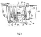
- FIG 1shows the structural frame of a lift-recliner chair 10 according to an embodiment of the present invention.
- the frameand hence the chair, comprises three main sections including a base portion 12 a seat portion 14 and a back portion 16.
- the base portionincludes a pair of lateral side panels 18 and a rear panel 20 secured to the respective sides of the rectangular metal frame 22 on the underside of the chair.
- the panels 18 and 20 and the other panels of the frame of the chair shown in Figures 1 to 5are preferably of MDF type board material but the invention also contemplates other board material such as wood, plywood or plastic etc. as is typically used in the furniture industry for upholstered and non-upholstered furniture
- the metal frame 22comprises a pair of lateral side members 24, a front cross member 26 extending between the side members 24 at the front of the chair and a pair of intermediate cross members 28 and 30 which extend between the side members 24 at a point midway along the length of the side member and towards the rear of the chair respectively.
- the side panels 18are secured to the side members 24 of the frame with the rear panel 20 secured to the ends of the respective side panels at the rear of the chair to provide a box-type structure for supporting the other parts of the chair.
- the base portion 12further comprises a front panel 32 which is pivotally mounted to the lateral side panels 18 of the base by a linkage arrangement 34 at both ends of the panel 32 adjacent to the respective side panels 18.
- the linkage arrangement 34is of a known arrangement and enables the front panel 32 to be moved from the position shown in Figure 1 , where it has a generally vertical orientation, to the position shown in Figure 2 , where it has a substantially horizontal configuration.
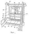
- the seat portion 14comprises a similar box-type panel frame secured to a further metal rectangular frame 36, as can best be seen in the view of Figure 3 .
- the metal frame 3 6includes a pair of lateral side members 3 8 to which the lateral side panels 40 of the seat are attached, a front cross member 42 at the front of the seat portion, a rear cross member 44 at the rear of the seat and an intermediate cross member 46 approximately midway between the front member 42 and rear member 44.
- the cross membersextend between the side members 38.
- the rectangular frame section between the cross members 44 and 46 at the rear of the seathas a slightly reduced width dimension to that of the rectangular frame section between the front cross member 36 and intermediate member 46. For reasons that will become apparent later in this description this reduced width dimension provides a clearance between the side members 38 of the frame and the respective side panels 40 of the seat towards the rear of the chair.
- the clearance dimensionis approximately equal to the width dimension of the metal tubes that constitute the metal frame.
- the seat portion 14is nested within the base portion 12 and pivotally connected to the base portion about a pivot axis perpendicular to the lateral sides 40 at the front of the chair.
- the seat portionis pivotally mounted to the base portion by pivot pins (not shown) which extend from pivot plates 48 through corresponding apertures in the side panels 40 and 18 towards the front of the chair.
- the rear most ends of the side panels 40are arcuate having a centre of curvature defined by the pivot axis of the mounting pins so that the rear part of the seat portion can move freely with respect to the base end panel 20 when the seat portion is pivoted about its axis in use.
- an end panel 50as seen in Figure 4 which extends between the side panels 40 at the rear of the chair also has a curvature which follows the curvature of the arcuate end faces 49, that is to say it has the pivot axis of the seat portion as its centre of curvature.
- the width dimension of the seat portion between the side panels 40is slightly less than the width dimension between the base side panels 18 so that the seat portion nests between the side panels 18 when in the sitting configuration shown in Figure 1 and is extendable telescopically there from when pivoted about its pivot axis to the lift position shown in Figure 5 .
- the back portion of the chair framealso comprises a rectangular frame in which a pair of a pair of elongate pivot arms 52 on the lateral sides of the back portion 16.
- the arms 52are joined together by a pair of cross members 54 and 55 towards the top and the bottom part of the back portion 16.
- the back portion 16is pivotally connected to the seat portion 14 in the same way that the seat portion is pivotally connected to the base 12, that is to say by means of a pair of pivot pins 56 secured to pivot pin plates 58 on the respective side panels 40.
- the pins 56pass through corresponding apertures in the respective panels 40 and pivot arms 52.
- the pivot arms 52extends beyond the pivot pins S6 into the interior region of the base portion 12.
- the lower part of the pivot arms 52pass through the gaps created between the undersize frame part towards the rear of the frame 36 and the side panels 40 on the seat.
- the ends of the pivot armsextend beyond the metal seat frame 36 into the region on the underside of the frame 36 and are joined together at their remote ends by a metal cross bar member 60.
- the pivot arms 52are free to rotate with respect to the seat portion, and hence the base portion, in a manner that enables the back portion to be reclined with respect to the seat portion either for altering the configuration of the chair from an upright configuration to a reclined configuration or to a raised configuration as shown in Figure 5 .
- Three linear actuators 62, 64 and 66are mounted on the metal frame 22 in the interior of the base portion 12 on the underside of the seat frame 36.
- a first of the actuators 62is mounted on the intermediate cross member 28 with the end of the actuator ram 63 fixed to the rear face of the front panel 32 adjacent to the upper edge 70 of the front panel.
- Extension of the actuator arm 63moves the front panel from its generally vertical orientation as shown in Figure 1 to the horizontal orientation shown in Figure 2 to provide a footrest support.
- Actuator 64is mounted to the front cross member 26 of the frame 22.
- the actuator arm 65 of the actuator 64is connected at its extendable end to the cross member 46 of the metal seat frame 36 so that extension of the actuator arm 65 moves the seat portion 14 about its pivot access to tilt the seat portion between the positions shown in Figures 1 and 5 .
- the third actuator 66is also mounted to the cross member 26 of the metal frame 22 with the extendable end of its actuator arm 67 connected to the cross member 60 extending between the pivot arms 52. Extension of the actuator arm 67 by the actuator 66 moves the back portion 16 about its pivot access to alter the tilt angle of the back portion 16 with respect to the seat portion 14. Retraction of the actuator arm 67 causes the angle between the back portion and seat portion to increase, for example when the chair is reclined or when the seat portion 14 is raised to the standing position. Extension of the actuator arm 67 reverses this operation and when fully retracted the back portion is moved to its upright position with respect to the seat portion.
- Actuators 62, 64 and 66are of a known type, for example Dewart type 34931 linear actuators, that comprise electrical motors controlled by control electronics which may be in the form of a microprocessor suitably programmed to provide co-ordinated control of the actuators for co-ordinated movement of the moveable sections of the chair, both for reclining and lifting movements.
- control electronicswhich may be in the form of a microprocessor suitably programmed to provide co-ordinated control of the actuators for co-ordinated movement of the moveable sections of the chair, both for reclining and lifting movements.
- the configuration of the chair shown in Figures 1 to 5may be changed from the upright configuration shown in Figure 1 to a reclined configuration where the back portion 16 is reclined with respect to the remainder of the chair and the front panel 32 is raised to provide a foot rest with or without movement of the seat portion 14, and that the configuration may be changed from the upright configuration to the raised configuration shown in Figure 5 for assisting the seated user out of the chair.
- the seat portion 14is tilted to the raised configuration shown in Figure 5 with the back portion 16 remaining in its upright configuration this could cause problems by dictating or even forcing an individual to move out of the chair directly from a seated position. Adjusting from a seated position to a standing position as the seat portion tilts forward may not be possible or desirable for all users. If the back portion 16 is moved to its reclined position prior to or during movement of the seat portion 16 then a user can be placed into a standing position by the chair by the time the seat portion 16 has tilted to the point at which the user leaves the chair. The chair may therefore have the facility to provide co-ordinated pivotal movement of the seat portion 14 and the back portion 16 in which the back portion 16 reclines as the seat portion 14 lifts.
- the back portionbegins to tilt rearwards when the seat portion is pivoted, or raised, at a point half way between its lowered and raised positions, preferably the movement of the seat and back rest - portion is co-ordinated by control signals generated by software implemented in the microprocessor controller.
- a recliner chaircomprises an operating mechanism as shown in the drawing of Figure 6.
- Figure 6is a cross section view through the base portion of a recliner chair with an operating mechanism 71 housed substantially within the interior of the base of the chair.
- the base of the chair shown in Figure 6is similar to the base of the chair described with reference to Figures 1 to 5 in that it comprises a generally rectangular box-type structural framework including a metal base frame 72, of a tubular metal construction, and a pair of lateral side panels 74, preferably but not necessarily of MDF board material, bolted to the side members of the frame 72 on respective sides of the chair.
- a front panel 76is pivotally mounted to the side panels 74 by respective link assemblies 78 mounted on the interior side of the side panels 74 on both sides of the chair.
- the link assembly 78 and front panel 76are substantially identical to the linkage system 34 and front panel 32 of the chair described with reference to Figures 1 to 5 .
- the link assembly 78 on each side of the chairincludes four link elements that are pivotally connected together, including a first link element 80 which is pivoted at one end to the side panel 74 and at its other end to one end of a second link element 82.
- the other end of the link element 82is pivotally connected to a bracket 83 secured to the interior facing surface of the front panel 76 towards the top edge of the panel when configured in its vertical orientation as shown in Figure 6 .
- a third link element 84is pivotally connected at one end thereof to the side panel 74 between the link element 80 and the front panel 76 and at the other end thereof to one end of a fourth link element 86, the other end of which is also pivotally connected to the bracket 83 at a position spaced from the link 82 and approximately one third along the depth of the front panel 76.
- the second and third link elements 82 and 84are also pivotally connected together at the point of their mutual intersection (not shown).
- the front panel 76is deployed from its vertical orientation shown in Figure 6 to a generally horizontal orientation to provide a foot rest by activation of a linear actuator 88 located within the interior of the base of the chair.
- the linear actuator 88may be a Dewart type 34931 linear actuator comprising an electric motor 90 at one end thereof and a piston arm 92 at the other end thereof which is extendable from a housing 94.
- the end of the actuator 88 nearest the motor section 90is pivotally connected to a bracket 96 integral with and upstanding from the base frame 72 at the front of the frame 72.
- the extendable arm 92is pivotally connected at its end to a bracket 98 extending on one side of a square cross section metal tube member 100 to which extends along the width of the chair and is welded to respective metal bell-crank plates 102 at opposite sides of the chair, only one of which is shown in the cross-section view of Figure 6 .
- the bell-crank plates 102are substantially parallel with the respective side panels 74 and perpendicular to the metal tube which connects the bell-crank plates 102 on either side of the chair together.
- Each bell-crank plate 102is pivotally connected to its respective side panel 74 by a pin type mounting 104 positioned towards the top edge 106 of the side panel 74.
- Each bell-crank plate 102is provided with an upstanding engagement pin 108 extending perpendicular to the plane of the plate.
- the pin 108constitutes a cam engagement means and is engaged within respective first and second cam slots 110 and 112 provided in the respective cam plates 114 and 116 pivotally mounted to the respective side-panels 74 towards the rear of the chair on both sides thereof.
- the first and second cam plates 114 and 116are pivotally mounted on a common pivot pin 118 which extends into the interior of the base portion from the side panel 74.
- the cam plates 114 and 116are generally planar and parallel with the bell-crank 102 and the side panel 74.
- the first cam plate 114constitutes a seat back cam for determining the movement path of the back portion of the chair (not shown) with respect to the base.
- the second cam plate 116constitutes a footrest cam for determining the movement path of the front panel 76 with respect to the side panels of the base.
- the seat back cam 114has a shallow V-shape with the mounting pin 118 positioned at the apex of the V.
- the upper arm of the Vi.e. the arm shown towards the top of the drawing in Figure 6 , constitutes a lever for connecting the seat back cam plate to the back portion of the chair, while the cam slot 110 is formed in the lower arm of the V.
- the cam slot 110includes a linear portion 120 and an arcuate portion 122 with the linear portion 120 extending towards the extremity of the V and the arcuate portion disposed towards the middle part of the V in the lower arm.
- the curvature of the arcuate portion 122is such that the side of the slot facing the front of the chair in the view of Figure 6 is concave.
- the cam plate 116is generally arcuate and is pivotally connected at one end of the arc to the mounting pin 118 and at its other end to a linear push rod link element 124.
- the cam slot 112 in the cam plate 116also comprises a linear section 126 and a longer arcuate section 128.
- the arcuate section 128 of the slotextends along the majority of the arcuate length of the cam plate from the lower end of the plate that is connected to the push rod 124 along approximately 75% of the arc of the plate where the remainder of the slot is linear.
- the linear push rod 124connects the link assembly 78 to the cam plate 116.
- One end of the push rod 124is pivotally connected to the first link 80 at a point substantially midway along its length, and the other end is pivotally connected to the cam plate 116.
- the operating mechanism described with reference to Figure 6provides for simultaneous co-ordinated pivotal movement of the back of the chair and the foot rest front panel 76.
- the operating mechanismis shown configured for a chair in an upright configuration with the front panel foot rest 76 retracted to the vertical position at the front of the chair and the back portion of the chair substantially upright with respect to the base and seat.
- the actuator 88By activating the actuator 88 to retract the arm 92 into the housing 94 the bell crank 102 is caused to rotate about the pin 104.
- This movementcauses the cam engagement pin 108 to follow a circular path about the centre of the pin 104, in a clockwise direction when viewed in the plane of the drawing of Figure 6 .
- the fixed relationship between the position of the pin 118 and the end of the push rod 124 connected to the plate 116causes the push rod link 124 to move in a general direction towards the front panel of the chair pivoting the links 80 and 84 of the link assembly also in a clockwise direction so that the front panel 76 is moved from the vertical position shown in Figure 6 towards its deployed horizontal position to provide a foot rest.
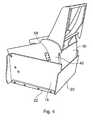
- FIGS 7 to 13show a lift-recliner chair 210 according to an alternative embodiment of the present invention.
- the chair 210is similar to the chair 10 shown in Figures 1 to 5 .
- the chair 210comprises a base portion 212, a seat portion 214 and a back portion 216.
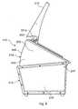
- the seat portion 214is pivoted with respect to the base portion 212 and is movable between the lowered position shown in Figure 7 and the raised position shown in Figures 8 and 9 .
- the back portion 216is pivoted with respect to the seat portion 214 and is movable between the raised position shown in Figure 7 and the reclined position shown in Figure 10 ; in addition a front panel 232 is pivoted with respect to the base portion 212 and can be moved from the vertical position of Figure 7 , and best shown in Figure 13 , to the horizontal position shown in Figure 10 .
- the base portion 212includes a pair of lateral side panels 218 and a rear panel 220 is secured to the rear of the side panels 218. Together with the front panel 232 the base portion 212 comprises a box-type structure.
- the side panels 218are joined at their lower edges to a metal base frame 222 comprising a pair of lateral side members 224, a front cross member 226 extending between the side members 224 at the front of the chair and an intermediate cross member 230 which extends between the side members 224 towards the rear of the chair.
- the seat portion 214comprises a pair of lateral side panels 240 joined by a central, mainly wooden, rectangular frame 236.
- the frame 236comprises a pair of side members 23 8 and front and rear cross members 242, 244 extending between the front and rear side members 238.
- the side members 238are attached to the side panels 240 by a pair of metal reinforcement brackets 241.
- a metal cross member 237is attached to and extends between the panels 240 and is also attached to the frame side members 238.
- a further cross member 219is attached to and extends between the side panels 240 directly below the cross member 237 at the lower rear corners of the panels 240.
- the seat portion 214is nested within the base portion 212 and is pivotally connected to the base portion 212 about a pivot axis perpendicular to the side panels 240 by pivot pins 247.
- the pins 247extend from pivot pin mounting plates 248 positioned at the respective upper front corners of the side panels 240 and extend through the panels 240 and through the side panels 218 of the base portion 212.
- the rear ends of the side panels 240are arcuate and an end panel 250 extending between the side panels 240 is correspondingly curved.
- the centre of curvature of the rear ends of the side panels 240 and the end panel 250is determined by the pivot axis 247 of the seat portion so that the seat portion 214 can extend and retract telescopically, with minimum clearance, within the base portion 212 between the lowered position shown in Figure 7 and the raised position shown in Figures 8 and 9 .
- the back portion 216comprises a pair of elongate pivot arms 252 joined by a top cross member 254, an intermediate cross member 257 and a bottom cross member 255.
- Two outer arms 259lie outwardly spaced from and parallel to the pivot arms 252.
- the arms 259are connected by the top cross member 254 and the intermediate cross member 257, and terminate slightly below the bottom of the pivot arms 252.
- the three cross members 254, 255, 257aid in the attachment of webbing (not shown) in the upholstering of the chair 210.
- the pivot arms 252are provided with metal brackets 203 for mounting the back portion 216 on corresponding interlocking bracket parts 201 a of L-shape bell crank members 201.
- a metal cross member 260extends between and is fixed to the L-shape members 201.
- the pivot arms 252thereby slot into the respective leg 201 a portions of the L-shape member 201.
- the other leg portions 201b of the L-shaped brackets 201connect the brackets to respective pivot pins 256 extending through the panels 240.
- the back portion 216is thereby pivotally connected to the seat portion 214.
- three linear actuators 262, 264, 266are provided within the base portion for movement of the front panel 232, the seat portion 214 and the back portion 216 respectively.
- the actuator 262is mounted centrally on the rear cross member 230 with the actuator ram 263 fixed to the rear face of the front panel 232 via a bracket 235.
- the actuator 263is of the 'push only' type in which the piston is not attached to the screw jack (not shown). Accordingly the actuator 262 can move the panel 232 from the vertical position shown in Figure 7 to the horizontal position shown in Figure 10 .
- the return actionis provided not by the actuator 262, but by the weight of the panel 232 and by a lightly tensioned elastic cord 234 strung between bolts 234a, 234b which extend from the points of connection of the two ends of the actuator 262 to the panel 232 and the cross member 228 respectively. Because the actuator 262 is not involved in the return movement of the panel, if an object, such as a leg or arm, becomes trapped by the panel 232 as it moves towards the vertical position then the object is held only by the weight of the panel 232 and the tension of the cord 234. Accordingly the force applied to the object by the panel 232 is minimised and can easily be overcome compared to a system using an actuator to effect the return action.
- the panel 232is connected to the base portion 212 via two hinges 233, one at either side of the panel 232.
- Each hinge 233comprises an arcuate quarter circle plate 233a connected at one of its circumferential ends to the panel 232 and at its other circumferential end to a linear radially extending plate 233b.
- the linear plate 233bis pivotally connected to the base side panels of the chair by the pivot pins 247 extending from the base portion side panels 218 through the linear plates and through the side panels 240 of the seat section to the mounting plates 248.
- pivot pins 247thereby defines the pivot axis for both the panel 232 and the seat portion 214.
- This arrangementalso means that the hinges 233 slide between the side panels 240 of the seat portion 214 and the side panels 218 of the base portion 212 when extended and retracted.
- the panel 232is connected to the base portion 212 via hinges 233 the panel 232 can undergo only a rotation movement with no radial extension. As a result the position of the panel 232 may not extend away from the chair sufficiently to suit all users. Accordingly, in other embodiments (not shown) the chair may have some means of increasing the distance the panel extends away from the seat portion 214.
- the panel 232 or a part thereofmay be telescopic so that it moves to a position further away from the seat portion 214 during or following the pivoting movement.
- a 'flipper board' arrangementcould be used, in which a further panel is pivotally attached to the main foot panel 232 and can be flipped over from a position in which it rests on the panel 232 to a position in which it is coextensive with the panel 232 to increase the length of the panel.
- the actuator 264is mounted centrally on the front cross member 226.
- the actuator ram 265is fixed centrally to a cross member 237 which spans between and is attached to the side panels 240 and supports the rear of the seat section frame 236.
- the front of the seat section frame 236is carried on a pair of brackets 241 attached to the frame members 238 and to the inner faces of the side panels 240.
- the side panels 240are pivotally connected to the main pivot points so that the seat portion 214 pivots about the pivot points under the control of the actuator 264 as shown in Figures 8 and 9 .
- the actuator 266is mounted centrally on a cross member 219 which extends between and is fixed to the side panels 240 of the seat portion.
- the actuator ram 267 of actuator 266is connected centrally to the cross member 260 at a point offset from the pivot axis 256 to provide a bell crank type lever.
- the bell crank arrangementmeans that the back portion 216 can be lowered to the position shown in Figure 10 by retracting the ram 267, or raised to the position shown in Figure 7 by extending the ram 267.
- the back portion 216can be moved at the same time as movement of the seat portion 214 and/or the footrest panel 232 or independently thereof as previously described with reference to the embodiment of Figures 1 to 5 .
- the lift recliner chair described with reference to Figures 1 to 5may be modified to provide a reclining function only in the sense that the base portion of the chair is provided with only two actuators, one for reclining the back portion of the chair with respect to the base and a fixed seat, and another for deploying the front panel from its vertical position to its horizontal position to provide a foot rest for the chair.
Landscapes
- Health & Medical Sciences (AREA)
- Dentistry (AREA)
- General Health & Medical Sciences (AREA)
- Chairs For Special Purposes, Such As Reclining Chairs (AREA)
- Lubricants (AREA)
- Table Devices Or Equipment (AREA)
- Lock And Its Accessories (AREA)
- Seats For Vehicles (AREA)
- Valve-Gear Or Valve Arrangements (AREA)
- Steroid Compounds (AREA)
- Chair Legs, Seat Parts, And Backrests (AREA)
Abstract
Description
- This invention relates to powered furniture and in particular concerns powered recliner chairs and lift-recliner chairs.
- A typical recliner chair comprises a base that sits on the floor, a seat portion that supports a generally horizontal seat cushion and a back portion that may be fixed to the seat or pivotally connected to it. Recliner chairs are also usually provided with a footrest at the front of the chair which is movable between a vertical orientation when the chair is in a generally upright configuration for sitting, and a generally horizontal orientation when the chair is reconfigured for reclining. Recliner chairs are known where the seat portion moves during the reclining operation to tilt the seat slightly downwards at the rear edge and raise the front edge of the seat. Other types of recliner seat are known where the seat is fixed with respect to the base and only the back and footrest are moved when the seat is reclined.
- Various types of lift-recliner chairs have been developed, principally for the elderly and less physically able people, to provide assistance when moving out of the chair to a standing position. Typical lift recliner chairs are described in
US-A-4,852,939 ,US-A-4,993,777 andUS-A-5,265,935 which describe various arrangements of levers, links and motors for raising the chair from a seated to a standing position. - The actuating arrangements of known recliner and lift-recliner chairs are generally mechanically complex adding significantly to the cost, weight and complexity of the chair. In addition, in known lift-recliner chairs the seat and back portion of the chair are typically lifted off of the base support structure (typically a metal frame) when the chair is raised towards the standing position creating entrapment points between the underside of the seat and the base, and in particular in between the levers and links of the actuating arrangement that are exposed between the seat and the base support structure when the chair is raised.
- There is a requirement to provide a simple actuating arrangement for recliner and lift-recliner chairs which requires fewer moving components than hitherto known designs, and also an actuating arrangement that is relatively simple to construct and to integrate within the structure of a recliner or lift recliner chair.
- According to an aspect of the present invention there is provided a power operated lift-recliner chair comprising a base portion, a seat portion pivotally connected to the base portion, a back portion pivotally connected to the seat portion and powered actuator means for moving the seat portion with respect to the base portion and the back portion with respect to the seat portion to alter the configuration of the chair, wherein the base portion includes a pair of substantially vertical side panels and a rear panel extending between the said side panels at the rear of the chair, and the said seat portion includes a seat frame having a pair of substantially vertical side panels arranged substantially parallel with and adjacent to the respective base portion side panels, the said actuator means is substantially enclosed within the base portion in all configurations of the chair and the seat portion is movable between a substantially horizontal position in which at least part of the seat portion is nested with the base portion and an inclined position in which the seat is telescopically extended from the base.
- The lift-recliner chair according to the above aspect of the invention has the advantage that the actuator means is enclosed within the base portion of the chair, thereby providing a chair in which the actuator means is wholly integrated within the structure of the chair. This can substantially eliminate the risk of entrapment when the chair is moved from one configuration to another, for example when raised or lowered. The lift-recliner chair according to this aspect of the invention also enables all moving parts of the actuating mechanism to be enclosed within the base portion of an upholstered chair.
- The seat portion of the chair is movable between a substantially horizontal position in which at least part of the seat portion is nested with the base portion and an inclined position in which the seat is extended telescopically from the base. The nested arrangement of the seat portion and the base readily enables the actuator means to be enclosed within the base on the underside of the seat cushion part of the seat portion so that the actuator means is guarded by the base and seat structure and also hidden from view so that the aesthetic appearance of the chair is also significantly improved. It will be readily apparent to the skilled person that by carefully selecting the clearance dimensions between the nested parts of the chair entrapment points can be substantially eliminated. This is a significant advantage when considered in relation to known types of lift recliner chair where a significant risk of entrapment exists between the moving parts on the underside of the seat portion of the chair between the seat and the base and between the seat and the base parts when the seat is moved.
- In preferred embodiments the seat portion is nested within and extendable from the base portion.
- The base portion comprises a front and a back panel and a pair of substantially vertical side panels between the front and back panels, and the said scat portion comprises a seat panel and pair of substantially vertical side panels arranged substantially parallel with and adjacent to the respective base portion side panels.
- Preferably, the base portion has a rectangular shape with the side and back panels comprise part of the structural framework of the chair with the front panel being movable with respect to the other panels of the base to a horizontal orientation to provide a foot rest.
- Preferably, the seat portion is pivoted to the base portion about a pivot axis positioned towards the front of the base portion, that is to say towards the front panel of the base. In this way it is possible to raise and lower the seat portion of the chair by tilting the seat portion about its pivot axis to provide the lifting function of the chair. By positioning the pivot axis towards the front of the chair the person seated in the chair can be gently raised towards the standing position with substantially no effort since the movement of the seat gently straightens the legs of the person seated since the knee joints of the user's legs are substantially coincident with the pivot axis as the seat is pivoted and raised.
- In preferred embodiments the back portion comprises a generally rectangular frame and a pair of pivot arms which extend from the frame and pivotal ly connect the frame to the seat portion. In this way the pivot arms may comprise part of a bell-crank arrangement for moving the back portion about a pivot axis spaced from the rectangular frame of the seat back. The extended pivot arms readily enable the back portion to be moved by actuator means enclosed within the enclosed region on the underside of the seat or at the rear of the seat cushion. This is possible in embodiments where the pivot arms extend into the region on the underside of the seat panel, or into the region at the rear of the seat cushion, where they can be connected to an actuator without interfering with other parts of the seat.
- In preferred embodiments the pivot arms extend parallel with and adjacent to the respective vertical side panels of the seat, and preferably the pivot arms are positioned on the interior side of the vertical side panels of the seat.
- Preferably the back portion pivots away from the seat portion when the seat is moved to an inclined position, that is to say the angle between the seat panel and the seat back is increased. Preferably, the back portion pivots away from the seat portion when the seat is moved to a half raised position.
- In preferred embodiments the seat and back portions of the chair are moved independently of each other by dedicated first and second actuators, including a first actuator for moving the seat portion and a second actuator for moving the back portion. The first and second actuators are preferably controlled by a microprocessor or the like so that the movements of the seat and back portions of the chair are co-ordinated.
- Preferably, the first and second actuators are mounted in fixed relation to the base portion of the chair. In preferred embodiments the actuators arc fixed to a structural, preferably metal, frame on which the side and rear panels of the base are mounted, In other embodiments the first actuator for moving the seat portion is fixed to the base and the second actuator for moving the back portion is fixed relative to the seat portion.
- The front panel of the base portion is preferably pivotally mounted with respect to the side and rear panels of the base so that it may be moved from a generally vertical orientation in the normal seated configuration of the chair to a generally horizontal orientation in a reclined configuration of the chair. In this embodiment a third actuator is provided for moving the front panel about its pivot axis. It is preferred that the third actuator is fixed in relation to the side panels of the base and preferably mounted to the same metal frame as the first and second actuators.
- Various embodiments of the present invention will now be more particular described, by way of example only, with reference to the accompanying drawings, in which:
Figure 1 is a perspective view from the front of the frame of the lift-recliner chair according to an embodiment of the present invention;Figure 2 is the perspective view of the frame of the chair shown inFigure 1 viewed from the underside of the chair frame;Figure 3 is a perspective view of a chair ofFigure 1 from above;Figure 4 is a perspective view of the frame of the chair ofFigure 1 viewed from the side showing the rear of the chair with the frame in a partly raised configuration;Figure 5 is a perspective view similar to that ofFigure 1 of the frame of the chair shown in a fully raised configuration;Figure 6 is a cross-section view through the base of a lift-recliner chair according to another embodiment of the invention;Figure 7 is a side view of a lift-recliner chair according to a further embodiment of the invention;Figure 8 is a side view of the chair ofFigure 7 shown with a seat portion in a raised configuration;Figure 9 is a perspective view of the rear of the chair ofFigure 8 ;Figure 10 is a side view of the chair ofFigure 7 shown with a back portion in a reclined configuration and a foot panel in a raised configuration;Figure 11 is a diagrammatic view of the back section of the chair ofFigures 7 to 10 ;Figure 12 is a diagrammatic perspective view showing the underneath of the chair ofFigures 7 to 11 ; andFigure 13 is a diagrammatic side view showing the working mechanisms of the chair ofFigures 7 to 12 .Figure 1 shows the structural frame of a lift-recliner chair 10 according to an embodiment of the present invention. The frame, and hence the chair, comprises three main sections including a base portion 12 aseat portion 14 and aback portion 16. The base portion includes a pair oflateral side panels 18 and arear panel 20 secured to the respective sides of therectangular metal frame 22 on the underside of the chair. Thepanels Figures 1 to 5 are preferably of MDF type board material but the invention also contemplates other board material such as wood, plywood or plastic etc. as is typically used in the furniture industry for upholstered and non-upholstered furniture- The
metal frame 22, best seen in the view ofFigure 2 , comprises a pair oflateral side members 24, afront cross member 26 extending between theside members 24 at the front of the chair and a pair ofintermediate cross members side members 24 at a point midway along the length of the side member and towards the rear of the chair respectively. Theside panels 18 are secured to theside members 24 of the frame with therear panel 20 secured to the ends of the respective side panels at the rear of the chair to provide a box-type structure for supporting the other parts of the chair. - The
base portion 12 further comprises afront panel 32 which is pivotally mounted to thelateral side panels 18 of the base by alinkage arrangement 34 at both ends of thepanel 32 adjacent to therespective side panels 18. Thelinkage arrangement 34 is of a known arrangement and enables thefront panel 32 to be moved from the position shown inFigure 1 , where it has a generally vertical orientation, to the position shown inFigure 2 , where it has a substantially horizontal configuration. - The
seat portion 14 comprises a similar box-type panel frame secured to a further metalrectangular frame 36, as can best be seen in the view ofFigure 3 . The metal frame 3 6 includes a pair of lateral side members 3 8 to which thelateral side panels 40 of the seat are attached, afront cross member 42 at the front of the seat portion, arear cross member 44 at the rear of the seat and anintermediate cross member 46 approximately midway between thefront member 42 andrear member 44. The cross members extend between theside members 38. The rectangular frame section between thecross members front cross member 36 andintermediate member 46. For reasons that will become apparent later in this description this reduced width dimension provides a clearance between theside members 38 of the frame and therespective side panels 40 of the seat towards the rear of the chair. The clearance dimension is approximately equal to the width dimension of the metal tubes that constitute the metal frame. - The
seat portion 14 is nested within thebase portion 12 and pivotally connected to the base portion about a pivot axis perpendicular to the lateral sides 40 at the front of the chair. The seat portion is pivotally mounted to the base portion by pivot pins (not shown) which extend frompivot plates 48 through corresponding apertures in theside panels - The rear most ends of the
side panels 40 are arcuate having a centre of curvature defined by the pivot axis of the mounting pins so that the rear part of the seat portion can move freely with respect to thebase end panel 20 when the seat portion is pivoted about its axis in use. Similarly, anend panel 50, as seen inFigure 4 which extends between theside panels 40 at the rear of the chair also has a curvature which follows the curvature of the arcuate end faces 49, that is to say it has the pivot axis of the seat portion as its centre of curvature. - The width dimension of the seat portion between the
side panels 40 is slightly less than the width dimension between thebase side panels 18 so that the seat portion nests between theside panels 18 when in the sitting configuration shown inFigure 1 and is extendable telescopically there from when pivoted about its pivot axis to the lift position shown inFigure 5 . - The back portion of the chair frame also comprises a rectangular frame in which a pair of a pair of
elongate pivot arms 52 on the lateral sides of theback portion 16. Thearms 52 are joined together by a pair ofcross members back portion 16. Theback portion 16 is pivotally connected to theseat portion 14 in the same way that the seat portion is pivotally connected to thebase 12, that is to say by means of a pair of pivot pins 56 secured to pivotpin plates 58 on therespective side panels 40. Thepins 56 pass through corresponding apertures in therespective panels 40 and pivotarms 52. As can best be seen in the view ofFigure 2 thepivot arms 52 extends beyond the pivot pins S6 into the interior region of thebase portion 12. The lower part of thepivot arms 52 pass through the gaps created between the undersize frame part towards the rear of theframe 36 and theside panels 40 on the seat. The ends of the pivot arms extend beyond themetal seat frame 36 into the region on the underside of theframe 36 and are joined together at their remote ends by a metalcross bar member 60. - The
pivot arms 52 are free to rotate with respect to the seat portion, and hence the base portion, in a manner that enables the back portion to be reclined with respect to the seat portion either for altering the configuration of the chair from an upright configuration to a reclined configuration or to a raised configuration as shown inFigure 5 . - Three
linear actuators metal frame 22 in the interior of thebase portion 12 on the underside of theseat frame 36. A first of theactuators 62 is mounted on theintermediate cross member 28 with the end of theactuator ram 63 fixed to the rear face of thefront panel 32 adjacent to theupper edge 70 of the front panel. Extension of theactuator arm 63 moves the front panel from its generally vertical orientation as shown inFigure 1 to the horizontal orientation shown inFigure 2 to provide a footrest support.Actuator 64 is mounted to thefront cross member 26 of theframe 22. Theactuator arm 65 of theactuator 64 is connected at its extendable end to thecross member 46 of themetal seat frame 36 so that extension of theactuator arm 65 moves theseat portion 14 about its pivot access to tilt the seat portion between the positions shown inFigures 1 and5 . Thethird actuator 66 is also mounted to thecross member 26 of themetal frame 22 with the extendable end of itsactuator arm 67 connected to thecross member 60 extending between thepivot arms 52. Extension of theactuator arm 67 by theactuator 66 moves theback portion 16 about its pivot access to alter the tilt angle of theback portion 16 with respect to theseat portion 14. Retraction of theactuator arm 67 causes the angle between the back portion and seat portion to increase, for example when the chair is reclined or when theseat portion 14 is raised to the standing position. Extension of theactuator arm 67 reverses this operation and when fully retracted the back portion is moved to its upright position with respect to the seat portion. Actuators - It will be understood that the configuration of the chair shown in
Figures 1 to 5 may be changed from the upright configuration shown inFigure 1 to a reclined configuration where theback portion 16 is reclined with respect to the remainder of the chair and thefront panel 32 is raised to provide a foot rest with or without movement of theseat portion 14, and that the configuration may be changed from the upright configuration to the raised configuration shown inFigure 5 for assisting the seated user out of the chair. - If the
seat portion 14 is tilted to the raised configuration shown inFigure 5 with theback portion 16 remaining in its upright configuration this could cause problems by dictating or even forcing an individual to move out of the chair directly from a seated position. Adjusting from a seated position to a standing position as the seat portion tilts forward may not be possible or desirable for all users. If theback portion 16 is moved to its reclined position prior to or during movement of theseat portion 16 then a user can be placed into a standing position by the chair by the time theseat portion 16 has tilted to the point at which the user leaves the chair. The chair may therefore have the facility to provide co-ordinated pivotal movement of theseat portion 14 and theback portion 16 in which theback portion 16 reclines as theseat portion 14 lifts. In this way an individual is moved from a seated to a standing position by the chair to avoid the possibility of them being pushed out of the chair whilst still in a seated position. In a preferred embodiment of the invention the back portion begins to tilt rearwards when the seat portion is pivoted, or raised, at a point half way between its lowered and raised positions, preferably the movement of the seat and back rest - portion is co-ordinated by control signals generated by software implemented in the microprocessor controller. - A recliner chair according to another aspect of the present invention comprises an operating mechanism as shown in the drawing of
Figure 6. Figure 6 is a cross section view through the base portion of a recliner chair with an operating mechanism 71 housed substantially within the interior of the base of the chair. The base of the chair shown inFigure 6 is similar to the base of the chair described with reference toFigures 1 to 5 in that it comprises a generally rectangular box-type structural framework including ametal base frame 72, of a tubular metal construction, and a pair oflateral side panels 74, preferably but not necessarily of MDF board material, bolted to the side members of theframe 72 on respective sides of the chair. - A front panel 76 is pivotally mounted to the
side panels 74 by respective link assemblies 78 mounted on the interior side of theside panels 74 on both sides of the chair. The link assembly 78 and front panel 76 are substantially identical to thelinkage system 34 andfront panel 32 of the chair described with reference toFigures 1 to 5 . The link assembly 78 on each side of the chair includes four link elements that are pivotally connected together, including afirst link element 80 which is pivoted at one end to theside panel 74 and at its other end to one end of asecond link element 82. The other end of thelink element 82 is pivotally connected to abracket 83 secured to the interior facing surface of the front panel 76 towards the top edge of the panel when configured in its vertical orientation as shown inFigure 6 . Athird link element 84 is pivotally connected at one end thereof to theside panel 74 between thelink element 80 and the front panel 76 and at the other end thereof to one end of afourth link element 86, the other end of which is also pivotally connected to thebracket 83 at a position spaced from thelink 82 and approximately one third along the depth of the front panel 76. The second andthird link elements - The front panel 76 is deployed from its vertical orientation shown in
Figure 6 to a generally horizontal orientation to provide a foot rest by activation of alinear actuator 88 located within the interior of the base of the chair. Thelinear actuator 88 may be a Dewart type 34931 linear actuator comprising anelectric motor 90 at one end thereof and apiston arm 92 at the other end thereof which is extendable from ahousing 94. The end of the actuator 88 nearest themotor section 90 is pivotally connected to abracket 96 integral with and upstanding from thebase frame 72 at the front of theframe 72. At the other end of the actuator theextendable arm 92 is pivotally connected at its end to abracket 98 extending on one side of a square cross sectionmetal tube member 100 to which extends along the width of the chair and is welded to respective metal bell-crankplates 102 at opposite sides of the chair, only one of which is shown in the cross-section view ofFigure 6 . The bell-crankplates 102 are substantially parallel with therespective side panels 74 and perpendicular to the metal tube which connects the bell-crankplates 102 on either side of the chair together. Each bell-crankplate 102 is pivotally connected to itsrespective side panel 74 by a pin type mounting 104 positioned towards thetop edge 106 of theside panel 74. Each bell-crankplate 102 is provided with anupstanding engagement pin 108 extending perpendicular to the plane of the plate. Thepin 108 constitutes a cam engagement means and is engaged within respective first andsecond cam slots respective cam plates panels 74 towards the rear of the chair on both sides thereof. The first andsecond cam plates common pivot pin 118 which extends into the interior of the base portion from theside panel 74. Thecam plates side panel 74. - The
first cam plate 114 constitutes a seat back cam for determining the movement path of the back portion of the chair (not shown) with respect to the base. Thesecond cam plate 116 constitutes a footrest cam for determining the movement path of the front panel 76 with respect to the side panels of the base. The seat backcam 114 has a shallow V-shape with the mountingpin 118 positioned at the apex of the V. The upper arm of the V, i.e. the arm shown towards the top of the drawing inFigure 6 , constitutes a lever for connecting the seat back cam plate to the back portion of the chair, while thecam slot 110 is formed in the lower arm of the V. Thecam slot 110 includes alinear portion 120 and anarcuate portion 122 with thelinear portion 120 extending towards the extremity of the V and the arcuate portion disposed towards the middle part of the V in the lower arm. The curvature of thearcuate portion 122 is such that the side of the slot facing the front of the chair in the view ofFigure 6 is concave. - The
cam plate 116 is generally arcuate and is pivotally connected at one end of the arc to the mountingpin 118 and at its other end to a linear pushrod link element 124. Thecam slot 112 in thecam plate 116 also comprises alinear section 126 and a longerarcuate section 128. Thearcuate section 128 of the slot extends along the majority of the arcuate length of the cam plate from the lower end of the plate that is connected to thepush rod 124 along approximately 75% of the arc of the plate where the remainder of the slot is linear. - The
linear push rod 124 connects the link assembly 78 to thecam plate 116. One end of thepush rod 124 is pivotally connected to thefirst link 80 at a point substantially midway along its length, and the other end is pivotally connected to thecam plate 116. - The operating mechanism described with reference to
Figure 6 provides for simultaneous co-ordinated pivotal movement of the back of the chair and the foot rest front panel 76. In the drawing ofFigure 6 the operating mechanism is shown configured for a chair in an upright configuration with the front panel foot rest 76 retracted to the vertical position at the front of the chair and the back portion of the chair substantially upright with respect to the base and seat. By activating theactuator 88 to retract thearm 92 into thehousing 94 the bell crank 102 is caused to rotate about thepin 104. This movement causes thecam engagement pin 108 to follow a circular path about the centre of thepin 104, in a clockwise direction when viewed in the plane of the drawing ofFigure 6 . This then causes thecam plate 114 to follow thepin 108 so that the cam plate rotates about the mountingpin 118 in a clockwise direction, as viewed in the plane of the drawing ofFigure 6 , thereby causing the back of the chair to rotate towards a reclined position with respect to the seat. Simultaneously, theslot 112 in thecam plate 116 is constrained to follow the movement of thecam pin 108 so that theplate 116 also rotates in a clockwise direction about the mountingpin 118. The fixed relationship between the position of thepin 118 and the end of thepush rod 124 connected to theplate 116 causes thepush rod link 124 to move in a general direction towards the front panel of the chair pivoting thelinks Figure 6 towards its deployed horizontal position to provide a foot rest. Figures 7 to 13 show a lift-recliner chair 210 according to an alternative embodiment of the present invention. Thechair 210 is similar to thechair 10 shown inFigures 1 to 5 .- The
chair 210 comprises abase portion 212, aseat portion 214 and aback portion 216. Theseat portion 214 is pivoted with respect to thebase portion 212 and is movable between the lowered position shown inFigure 7 and the raised position shown inFigures 8 and9 . Theback portion 216 is pivoted with respect to theseat portion 214 and is movable between the raised position shown inFigure 7 and the reclined position shown inFigure 10 ; in addition afront panel 232 is pivoted with respect to thebase portion 212 and can be moved from the vertical position ofFigure 7 , and best shown inFigure 13 , to the horizontal position shown inFigure 10 . - The
base portion 212 includes a pair oflateral side panels 218 and arear panel 220 is secured to the rear of theside panels 218. Together with thefront panel 232 thebase portion 212 comprises a box-type structure. - As shown in
Figures 12 and13 theside panels 218 are joined at their lower edges to ametal base frame 222 comprising a pair oflateral side members 224, afront cross member 226 extending between theside members 224 at the front of the chair and anintermediate cross member 230 which extends between theside members 224 towards the rear of the chair. - The
seat portion 214 comprises a pair oflateral side panels 240 joined by a central, mainly wooden,rectangular frame 236. Theframe 236 comprises a pair of side members 23 8 and front andrear cross members rear side members 238. - At the front of the
seat section frame 236 theside members 238 are attached to theside panels 240 by a pair ofmetal reinforcement brackets 241. At the rear of the seat section frame 236 ametal cross member 237 is attached to and extends between thepanels 240 and is also attached to theframe side members 238. Afurther cross member 219 is attached to and extends between theside panels 240 directly below thecross member 237 at the lower rear corners of thepanels 240. - The
seat portion 214 is nested within thebase portion 212 and is pivotally connected to thebase portion 212 about a pivot axis perpendicular to theside panels 240 by pivot pins 247. Thepins 247 extend from pivotpin mounting plates 248 positioned at the respective upper front corners of theside panels 240 and extend through thepanels 240 and through theside panels 218 of thebase portion 212. - The rear ends of the
side panels 240 are arcuate and anend panel 250 extending between theside panels 240 is correspondingly curved. As is the case for thechair 10 ofFigures 1 to 5 , the centre of curvature of the rear ends of theside panels 240 and theend panel 250 is determined by thepivot axis 247 of the seat portion so that theseat portion 214 can extend and retract telescopically, with minimum clearance, within thebase portion 212 between the lowered position shown inFigure 7 and the raised position shown inFigures 8 and9 . - As shown best in
Figure 11 , theback portion 216 comprises a pair ofelongate pivot arms 252 joined by atop cross member 254, anintermediate cross member 257 and abottom cross member 255. Twoouter arms 259 lie outwardly spaced from and parallel to thepivot arms 252. Thearms 259 are connected by thetop cross member 254 and theintermediate cross member 257, and terminate slightly below the bottom of thepivot arms 252. The threecross members chair 210. As can be seen inFigure 7 and8 thepivot arms 252 are provided withmetal brackets 203 for mounting theback portion 216 on corresponding interlockingbracket parts 201 a of L-shape bell crank members 201. - A
metal cross member 260 extends between and is fixed to the L-shape members 201. Thepivot arms 252 thereby slot into therespective leg 201 a portions of the L-shape member 201. Theother leg portions 201b of the L-shaped brackets 201 connect the brackets to respective pivot pins 256 extending through thepanels 240. Theback portion 216 is thereby pivotally connected to theseat portion 214. - As shown best in
Figures 12 and13 , threelinear actuators front panel 232, theseat portion 214 and theback portion 216 respectively. - The
actuator 262 is mounted centrally on therear cross member 230 with theactuator ram 263 fixed to the rear face of thefront panel 232 via abracket 235. Theactuator 263 is of the 'push only' type in which the piston is not attached to the screw jack (not shown). Accordingly theactuator 262 can move thepanel 232 from the vertical position shown inFigure 7 to the horizontal position shown inFigure 10 . - The return action is provided not by the
actuator 262, but by the weight of thepanel 232 and by a lightly tensionedelastic cord 234 strung betweenbolts actuator 262 to thepanel 232 and the cross member 228 respectively. Because theactuator 262 is not involved in the return movement of the panel, if an object, such as a leg or arm, becomes trapped by thepanel 232 as it moves towards the vertical position then the object is held only by the weight of thepanel 232 and the tension of thecord 234. Accordingly the force applied to the object by thepanel 232 is minimised and can easily be overcome compared to a system using an actuator to effect the return action. - The
panel 232 is connected to thebase portion 212 via twohinges 233, one at either side of thepanel 232. Eachhinge 233 comprises an arcuatequarter circle plate 233a connected at one of its circumferential ends to thepanel 232 and at its other circumferential end to a linearradially extending plate 233b. Thelinear plate 233b is pivotally connected to the base side panels of the chair by the pivot pins 247 extending from the baseportion side panels 218 through the linear plates and through theside panels 240 of the seat section to the mountingplates 248. - The main pivot point provided by
pivot pins 247 thereby defines the pivot axis for both thepanel 232 and theseat portion 214. This arrangement also means that thehinges 233 slide between theside panels 240 of theseat portion 214 and theside panels 218 of thebase portion 212 when extended and retracted. - The positioning of the combined main pivot points of the
foot rest 232 and the seat portion provided by the pivot pins 247 approximately at the upper front corners of thebase portion 212 andseat portion 214, coincides with the natural position of the seated user's knee joint which brings ergonomic advantages. The same advantage could, of course, be achieved if the pivot points for the front panel and the seat portion were slightly spaced apart but still in the same general area so that they are roughly coincident with the seated user's knee joint. - Because the
panel 232 is connected to thebase portion 212 viahinges 233 thepanel 232 can undergo only a rotation movement with no radial extension. As a result the position of thepanel 232 may not extend away from the chair sufficiently to suit all users. Accordingly, in other embodiments (not shown) the chair may have some means of increasing the distance the panel extends away from theseat portion 214. For example, thepanel 232 or a part thereof may be telescopic so that it moves to a position further away from theseat portion 214 during or following the pivoting movement. Alternatively a 'flipper board' arrangement could be used, in which a further panel is pivotally attached to themain foot panel 232 and can be flipped over from a position in which it rests on thepanel 232 to a position in which it is coextensive with thepanel 232 to increase the length of the panel. - The
actuator 264 is mounted centrally on thefront cross member 226. Theactuator ram 265 is fixed centrally to across member 237 which spans between and is attached to theside panels 240 and supports the rear of theseat section frame 236. The front of theseat section frame 236 is carried on a pair ofbrackets 241 attached to theframe members 238 and to the inner faces of theside panels 240. - As discussed above, the
side panels 240 are pivotally connected to the main pivot points so that theseat portion 214 pivots about the pivot points under the control of theactuator 264 as shown inFigures 8 and9 . Theactuator 266 is mounted centrally on across member 219 which extends between and is fixed to theside panels 240 of the seat portion. Theactuator ram 267 ofactuator 266 is connected centrally to thecross member 260 at a point offset from thepivot axis 256 to provide a bell crank type lever. The bell crank arrangement means that theback portion 216 can be lowered to the position shown inFigure 10 by retracting theram 267, or raised to the position shown inFigure 7 by extending theram 267. Theback portion 216 can be moved at the same time as movement of theseat portion 214 and/or thefootrest panel 232 or independently thereof as previously described with reference to the embodiment ofFigures 1 to 5 . - Although aspects of the invention have been described with reference to the embodiments shown in the accompanying drawings, it is to be understood that the invention is not so limited to those precise embodiments and that various changes and modifications may be effected without further inventive skill and effort. For example, the lift recliner chair described with reference to
Figures 1 to 5 may be modified to provide a reclining function only in the sense that the base portion of the chair is provided with only two actuators, one for reclining the back portion of the chair with respect to the base and a fixed seat, and another for deploying the front panel from its vertical position to its horizontal position to provide a foot rest for the chair. It will be appreciated that various changes and modifications may be made to the chairs described herein with any of the integers described in one embodiment being interchangeable with integers in another embodiment, and that the embodiments maybe modified by deletion or addition of any of the integers described with reference to any of the embodiments described herein, within the scope of the appended claims.
Claims (21)
- A power operated lift-recliner chair comprising a base portion (12), a seat portion (14) pivotally connected to the base portion, a back portion (16) pivotally connected to the seat portion and powered actuator means (64) for moving the seat portion with respect to the base portion and the back portion with respect to the seat portion to alter the configuration of the chair, wherein the base portion includes a pair of substantially vertical side panels (18) and a rear panel (20) extending between the said side panels at the rear of the chair, and the said seat portion (14) includes a seat frame (36) having a pair of substantially vertical side panel (40) arranged substantially parallel with and adjacent to the respective base portion side panels (18), wherein said actuator means (64) is substantially enclosed within the base portion (12) in all configurations of the chair, and the seat portion (14) is movable between a substantially horizontal position in which at least part of the seat portion is nested with the base portion and an inclined position in which the seat is telescopically extended from the base.
- A lift recliner chair as claimed in Claim 1 wherein the seat portion is nested within and extendable from the base portion
- A lift-recliner chair as claimed in Claim 1 or Claim 2 wherein the seat portion is pivoted with respect to the base portion about a pivot axis positioned towards the front of the base portion.
- A lift recliner chair as claimed in any preceding claim wherein the seat portion is pivotally connected to, and at least partially supported by, the said side panels of the base portion.
- A lift-recliner chair as claimed in any preceding claim wherein the back portion comprises a generally rectangular frame and a pair of pivot arms which extend from the frame and pivotally connect the frame to the seat portion.
- A lift recliner chair as claimed in Claim 5 wherein the pivot arms pivotally connect the back portion to the side panels of the seat portion.
- A lift-recliner chair as claimed in Claim 5 or Claim 6 wherein the pivot arms comprise part of a bell-crank arrangement for moving the back portion about a pivot axis spaced from the said rectangular frame.
- A lift-recliner chair as claimed in any one of Claims 5 to 7 wherein the pivot arms extend parallel with and adjacent to respective vertical side panels of the seat portion on an interior side thereof.
- A lift-recliner chair as claimed in any preceding claim wherein the said back portion pivots away from the seat portion when the seat portion is moved towards said raised inclined position.
- A lift recliner chair as claimed in Claim 9 wherein the said back portion is arranged to pivot away from the seat portion once the seat portion is moved to a predetermined position between its lowered and raised inclined positions.
- A lift-recliner chair as claimed in any preceding claim wherein the said powered actuator means comprises a first actuator for moving the said seat portion and a second actuator for moving the back portion.
- A lift-recliner chair as claimed in Claim 11 wherein the said first and second actuators are mounted in fixed relation to the base portion.
- A lift-recliner chair as claimed in Claim 11 wherein the said first actuator is fixed in relation to the base portion and the said second actuator is fixed in relation to the seat portion.
- A lift-recliner chair as claimed in any preceding claim wherein the base portion further comprises a front panel which is pivotally movable with respect to the side and rear panels of the base for movement from a generally vertical position to a generally horizontal position to provide a retractable foot rest.
- A lift-recliner chair as claimed in Claim 14 wherein the said actuator means comprises a third actuator fixed in relation to the fixed side panels of base for moving the said front panel about its pivot axis.
- A lift-recliner chair as claimed in Claim 14 or Claim 15 wherein the said front panel is pivotally moveable with respect to the base portion about a pivot axis corresponding substantially to the position of the seated user's knee joint.
- A lift recliner chair as claimed in any one of Claims 14 to 16 wherein the pivot axis of the said front panel is substantially coincident with the pivot axis of the seat portion with respect to the base portion.
- A lift-recliner chair as claimed in any preceding claim wherein the seat portion is pivotally connected to the said base portion about a first pivot axis and pivotally connected to the said back portion about a second pivot axis, and wherein the said rear panel of the said seat portion is curved having a centre of curvature substantially coincident with the said first pivot axis.
- A lift-recliner chair as claimed in Claim 18 wherein said seat portion rear panel comprises a rigid panel.
- A lift-recliner chair as claimed in any preceding claim wherein said base portion rear panel comprises a rigid panel.
- A lift-recliner chair as claimed in any preceding claim wherein the said base portion and seat portion side panels are rigid.
Applications Claiming Priority (2)
| Application Number | Priority Date | Filing Date | Title |
|---|---|---|---|
| GBGB0325358.0AGB0325358D0 (en) | 2003-10-30 | 2003-10-30 | Powered furniture |
| PCT/GB2004/004340WO2005051128A1 (en) | 2003-10-30 | 2004-10-13 | Adjustable reclining chair |
Publications (2)
| Publication Number | Publication Date |
|---|---|
| EP1689266A1 EP1689266A1 (en) | 2006-08-16 |
| EP1689266B1true EP1689266B1 (en) | 2008-06-25 |
Family
ID=29725655
Family Applications (1)
| Application Number | Title | Priority Date | Filing Date |
|---|---|---|---|
| EP04768871AExpired - LifetimeEP1689266B1 (en) | 2003-10-30 | 2004-10-13 | Adjustable reclining chair |
Country Status (17)
| Country | Link |
|---|---|
| US (4) | US7575279B2 (en) |
| EP (1) | EP1689266B1 (en) |
| JP (1) | JP4874804B2 (en) |
| CN (1) | CN1893857B (en) |
| AT (1) | ATE398949T1 (en) |
| AU (1) | AU2004292373B2 (en) |
| CA (4) | CA2748615C (en) |
| DE (1) | DE602004014637D1 (en) |
| DK (1) | DK1689266T3 (en) |
| ES (1) | ES2309559T3 (en) |
| GB (5) | GB0325358D0 (en) |
| MX (1) | MXPA06004682A (en) |
| MY (1) | MY137993A (en) |
| NZ (1) | NZ547258A (en) |
| TW (1) | TWI346533B (en) |
| WO (1) | WO2005051128A1 (en) |
| ZA (1) | ZA200604326B (en) |
Families Citing this family (84)
| Publication number | Priority date | Publication date | Assignee | Title |
|---|---|---|---|---|
| GB0325358D0 (en) | 2003-10-30 | 2003-12-03 | Peter Cook Internat Plc | Powered furniture |
| NL1026420C2 (en)* | 2004-06-15 | 2005-12-19 | Frencken Tristan | Device and method for moving persons between a sitting and a standing position. |
| GB2417895B (en) | 2004-09-13 | 2008-12-17 | Golden Technologies Inc | Lift chair and recliner |
| US20070096524A1 (en)* | 2005-11-01 | 2007-05-03 | Shang-Wei Chou | Corrective chair |
| US7461896B2 (en)* | 2006-06-30 | 2008-12-09 | Intel Corporation | System and device for monitoring and assisting human gross motor skills |
| US7492638B2 (en)* | 2006-11-20 | 2009-02-17 | Macronix International Co., Ltd. | Gated diode nonvolatile memory operation |
| US7766421B2 (en)* | 2006-12-21 | 2010-08-03 | L & P Property Management Company | Recliner lift chair with power lift and reclining units |
| GB0708053D0 (en) | 2007-04-26 | 2007-06-06 | Leuven | Adjustable furniture |
| GB2463076B (en)* | 2008-09-02 | 2013-05-08 | Brandvital Ltd | Articulated chairs |
| US7681945B1 (en)* | 2008-10-02 | 2010-03-23 | L & P Property Management Company | Wall-avoiding convertible ottoman |
| US8113574B2 (en)* | 2008-11-24 | 2012-02-14 | Ultra-Mek, Inc. | Rocking-reclining seating unit with power actuator |
| US20100205321A1 (en)* | 2009-02-12 | 2010-08-12 | Qualcomm Incorporated | Negotiable and adaptable periodic link status monitoring |
| WO2011021002A2 (en) | 2009-08-18 | 2011-02-24 | Integrated Furniture Technologies Limited | Adjustable furniture |
| US20110121625A1 (en)* | 2009-11-23 | 2011-05-26 | Safety Lift Chair Associates, LLC | Lift chair |
| US20110143043A1 (en)* | 2009-12-15 | 2011-06-16 | United Technologies Corporation | Plasma application of thermal barrier coatings with reduced thermal conductivity on combustor hardware |
| US8398165B2 (en)* | 2010-01-15 | 2013-03-19 | L & P Property Management Company | Powered rocker recliner linkage mechanism |
| US8398168B2 (en)* | 2010-01-15 | 2013-03-19 | L & P Property Management Company | Powered glider recliner linkage mechanism |
| EP2523578B1 (en)* | 2010-01-15 | 2015-06-17 | L&P Property Management Company | Powered rocker and glider recliner linkage mechanisms |
| US8356861B2 (en)* | 2010-01-26 | 2013-01-22 | Bose Corporation | Active suspension seat skirt |
| US8308228B2 (en)* | 2010-02-11 | 2012-11-13 | L & P Property Management Company | Zero-wall clearance linkage mechanism for a lifting recliner |
| US8696053B2 (en) | 2010-04-13 | 2014-04-15 | La-Z-Boy Incorporated | Furniture member having powered rocking motion |
| US8459732B2 (en) | 2010-04-13 | 2013-06-11 | La-Z-Boy Incorporated | Power actuated rocking furniture mechanism |
| US8783764B2 (en) | 2010-05-26 | 2014-07-22 | Ultra-Mek, Inc. | Power-assisted reclining lift chair with single power actuator |
| US10004334B2 (en) | 2010-09-09 | 2018-06-26 | Integrated Furniture Technologies Limited | Lift-recliner chair |
| GB201317259D0 (en)* | 2013-09-30 | 2013-11-13 | Integrated Furniture Technologies Ltd | Lift-recliner chair |
| GB201015084D0 (en) | 2010-09-09 | 2010-10-27 | Integrated Furniture Technologies Ltd | Lift-recliner chair |
| US8911009B2 (en) | 2010-11-08 | 2014-12-16 | Ultra-Mek, Inc. | Rocking-reclining seating unit |
| US8967718B2 (en) | 2010-11-08 | 2015-03-03 | Ultra-Mek, Inc. | Rocking-reclining seating unit |
| US20120126601A1 (en)* | 2010-11-18 | 2012-05-24 | Smith Vincent J | System, method and apparatus for assisting with standing from a seat |
| US9603453B2 (en)* | 2010-12-29 | 2017-03-28 | Ultra-Mek, Inc. | Reclining chair with tilting action to provide heart-rest position |
| US8973997B2 (en)* | 2011-07-19 | 2015-03-10 | Skip's Patents, Llc | Seat structure with sit-to-stand feature |
| US8608240B2 (en) | 2011-09-09 | 2013-12-17 | La-Z-Boy Incorporated | Mechanism and chair for powered combined and independent seat back and leg rest motion |
| US8944498B2 (en) | 2012-01-05 | 2015-02-03 | L & Property Management Company | Linkage mechanism for a dual-motor lifting recliner |
| US9050231B2 (en) | 2012-07-18 | 2015-06-09 | L&P Property Management Company | Seat-lift assembly |
| US9241855B2 (en) | 2012-09-12 | 2016-01-26 | La-Z-Boy Incorporated | Furniture member and power recline and lift mechanism |
| US8991925B2 (en) | 2012-09-12 | 2015-03-31 | La-Z-Boy Incorporated | Furniture member and power lift mechanism |
| WO2014152550A2 (en) | 2013-03-15 | 2014-09-25 | Stryker Corporation | Medical support apparatus |
| GB2518394A (en) | 2013-09-20 | 2015-03-25 | Sherborne Upholstery Ltd | Adjustable bed |
| US9743770B1 (en) | 2013-10-01 | 2017-08-29 | Golden Technologies, Inc. | Multi-positioning recliner chair |
| US9839292B2 (en) | 2014-04-08 | 2017-12-12 | John Hart Miller | Rotating and non-rotating reclining chairs w/tilting mechanisms |
| US9277822B1 (en) | 2014-09-02 | 2016-03-08 | La-Z-Boy Incorporated | Furniture member with powered mechanism providing lift and zero gravity positions |
| EP3193668A4 (en) | 2014-09-02 | 2018-05-02 | LA-Z-BOY Incorporated | Furniture member and power recline and lift mechanism |
| TWM490808U (en)* | 2014-09-09 | 2014-12-01 | chang-zhen Lin | Recreation chair structure |
| US9357847B2 (en)* | 2014-09-26 | 2016-06-07 | Ultra-Mek, Inc. | Reclining seating unit with power actuators |
| US10045621B1 (en)* | 2014-10-20 | 2018-08-14 | James Norbert Welter | Eternal chair |
| EP3229647A1 (en) | 2014-12-11 | 2017-10-18 | Integrated Furniture Technologies Limited | Adjustable furniture |
| GB201504140D0 (en) | 2015-03-11 | 2015-04-22 | Motus Mechanics Ltd | Adjustable bed |
| GB201610212D0 (en) | 2016-06-13 | 2016-07-27 | Motus Mech Ltd | Adjustable bed |
| US10236643B2 (en) | 2015-11-19 | 2019-03-19 | The Lovesac Company | Electrical hub for furniture assemblies |
| US11832039B2 (en) | 2021-04-12 | 2023-11-28 | The Lovesac Company | Tuning calibration technology for systems and methods for acoustically correcting sound loss through fabric |
| US11178486B2 (en) | 2015-11-19 | 2021-11-16 | The Lovesac Company | Modular furniture speaker assembly with reconfigurable transverse members |
| US10143307B2 (en) | 2015-11-19 | 2018-12-04 | The Lovesac Company | Furniture system with recliner assembly |
| US10212519B2 (en) | 2015-11-19 | 2019-02-19 | The Lovesac Company | Electronic furniture systems with integrated internal speakers |
| US10123621B2 (en) | 2015-11-19 | 2018-11-13 | The Lovesac Company | Furniture system recliner assembly with sled rails |
| US11178487B2 (en) | 2015-11-19 | 2021-11-16 | The Lovesac Company | Electronic furniture systems with integrated induction charger |
| US10979241B2 (en) | 2015-11-19 | 2021-04-13 | The Lovesac Company | Electronic furniture systems with integrated artificial intelligence |
| US11689856B2 (en) | 2015-11-19 | 2023-06-27 | The Lovesac Company | Electronic furniture systems with integrated induction charger |
| US9809131B2 (en)* | 2015-12-04 | 2017-11-07 | Ford Global Technologies, Llc | Anthropomorphic pivotable upper seatback support |
| US11020295B2 (en) | 2015-12-22 | 2021-06-01 | Stryker Corporation | Patient support systems and methods for assisting caregivers with patient care |
| US10021979B2 (en) | 2016-02-22 | 2018-07-17 | John Hart Miller | Rotating and non-rotating reclining chairs with tilting mechanisms |
| US10245195B2 (en)* | 2016-04-15 | 2019-04-02 | J&D Furniture LLC | Reclining armchair with lifting seat and extending footrest |
| US10813806B2 (en) | 2016-05-24 | 2020-10-27 | Stryker Corporation | Medical support apparatus with stand assistance |
| WO2018017540A1 (en) | 2016-07-19 | 2018-01-25 | Adient Luxembourg Holding S.à.r.l. | A vehicle seat including an adaptive lateral occupant support structure |
| CN106617858A (en)* | 2016-11-17 | 2017-05-10 | 嘉兴意合机电有限公司 | Electric adjustable seat system for old people |
| EP3987979B1 (en)* | 2017-02-10 | 2025-09-24 | Golden Technologies, Inc. | Recliner or lift and recliner chair with variable lift profile |
| SE542449C2 (en) | 2017-03-31 | 2020-05-05 | Permobil Ab | Tilt assembly for a powered wheelchair and a powered wheelchair comprising the same |
| DE202017103410U1 (en)* | 2017-06-07 | 2017-07-05 | Ciar S.P.A. | Seating and reclining furniture |
| GB201813009D0 (en) | 2018-08-09 | 2018-09-26 | Eevolv Ltd | A drive mechanism |
| US10632031B2 (en)* | 2018-08-21 | 2020-04-28 | Pride Mobility Products Corporation | Adjustable lift chair frame |
| US11382423B2 (en)* | 2018-09-18 | 2022-07-12 | Aim Design, Llc | Locker with reclining seat and roll-up door |
| US12167793B2 (en)* | 2018-11-14 | 2024-12-17 | Ohad Paz | Tilting/lifting chair |
| DE202019100213U1 (en)* | 2019-01-15 | 2019-01-31 | Ciar S.P.A. | armchair |
| GB201901010D0 (en) | 2019-01-24 | 2019-03-13 | Eevolv Ltd | Lay-flat chair |
| US11350803B2 (en)* | 2019-06-17 | 2022-06-07 | Medic, Inc. | Toilet with user weight-driven seat lift profile |
| US12376678B1 (en) | 2019-07-18 | 2025-08-05 | Aim Design, Llc | Locker with reclining seat and roll-up door |
| TWM589493U (en)* | 2019-09-05 | 2020-01-21 | 林長貞 | Seat composition structure |
| US11406190B2 (en)* | 2020-03-05 | 2022-08-09 | Direct Supply, Inc. | Recliner with extending stabilizer arms |
| US11805908B2 (en)* | 2020-03-05 | 2023-11-07 | Direct Supply, Inc. | Recliner with force-limited stabilizer arms |
| CN112691022B (en)* | 2020-12-08 | 2023-10-10 | 奥佳华智能健康科技集团股份有限公司 | Chair frame and sauna cabin |
| US11647840B2 (en) | 2021-06-16 | 2023-05-16 | The Lovesac Company | Furniture console and methods of using the same |
| CN216932489U (en)* | 2021-12-30 | 2022-07-12 | 常州匠心独具智能家居股份有限公司 | Horizontal armrest and sofa |
| US12396557B2 (en) | 2022-04-11 | 2025-08-26 | The Lovesac Company | Modular furniture and reclining assemblies |
| US12022949B2 (en) | 2022-10-13 | 2024-07-02 | Hidden Lake 822, Llc | Drive motor-linear actuator system for powered lift or powered reclining chairs |
| CN116350434A (en)* | 2023-02-28 | 2023-06-30 | 浙江联宜电机有限公司 | Auxiliary rising seat |
Citations (1)
| Publication number | Priority date | Publication date | Assignee | Title |
|---|---|---|---|---|
| US4852939A (en)* | 1987-10-23 | 1989-08-01 | Orthokinetics, Inc. | Device for converting a recliner chair to a recliner-lift chair |
Family Cites Families (38)
| Publication number | Priority date | Publication date | Assignee | Title |
|---|---|---|---|---|
| GB436475A (en) | 1934-07-25 | 1935-10-11 | Fred Robinson | Improvements in or relating to apparatus for weighing live animals |
| GB847170A (en) | 1957-06-19 | 1960-09-07 | Anton Lorenz | Reclining chairs |
| US3138402A (en)* | 1961-11-01 | 1964-06-23 | American Metal Prod | Invalid chair |
| US3302969A (en) | 1965-01-11 | 1967-02-07 | Pontiac Design Corp | Reclining platform rocking chair |
| US3338632A (en)* | 1966-02-09 | 1967-08-29 | Carl T Kleinsorge | Reclining chair |
| US3343871A (en)* | 1966-03-03 | 1967-09-26 | George H Yates | Automatically operated invalid chair |
| DE1729984B2 (en) | 1968-01-20 | 1975-12-18 | Himolla Polstermoebelwerk Gmbh, 8252 Taufkirchen | Lever adjustment gear for reclining chairs |
| US3588170A (en)* | 1969-07-03 | 1971-06-28 | La Z Boy Chair Co | Motor-operated reclining chair |
| US4007960A (en)* | 1975-04-30 | 1977-02-15 | Gaffney Edward J | Reclining elevator chair |
| US4077663A (en)* | 1976-05-05 | 1978-03-07 | Mohasco Corporation | Recliner loungers |
| US4367895A (en)* | 1980-05-29 | 1983-01-11 | La-Z-Boy Chair Company | Reclinable chair |
| US4386803A (en)* | 1981-11-05 | 1983-06-07 | Gilderbloom Clarence W | Motorized reclining chair |
| SE449164B (en)* | 1984-03-12 | 1987-04-13 | Henning Bergenwall | MOBILE INCLUDING A STAND, ONE SEAT AND RELATIVELY SET SWINGABLE SEAT |
| FR2586914B1 (en)* | 1985-09-09 | 1987-12-04 | Erton | REST SEAT WITH INDEPENDENT CONTROLS |
| IT1200176B (en)* | 1986-07-18 | 1989-01-05 | Castellini Spa | STRUCTURE FOR ARMCHAIRS WITH SEAT AND MOBILE BACK, IN PARTICULAR FOR DENTAL USE |
| US5098158A (en)* | 1989-08-17 | 1992-03-24 | Palarski Timothy D | Articulated relaxation chair |
| US5024486A (en)* | 1990-04-03 | 1991-06-18 | Auel Carl C | All-purpose rocking, swiveling, reclining, and lifting chair |
| US5312153A (en)* | 1990-07-23 | 1994-05-17 | Ortho-Kinetics, Inc. | Recline lift wall hugger chair |
| ATE168336T1 (en)* | 1990-11-14 | 1998-08-15 | Invacare Corp | TILTABLE WHEELCHAIR WITH OPERATED OR SELF-PROPELLED MODE |
| CA2029917C (en)* | 1990-11-14 | 2003-01-21 | Richard Eakins | Adjustable chair |
| US5165753A (en)* | 1991-01-02 | 1992-11-24 | Henderson Eldred D | Elevator chair apparatus |
| US5222286A (en)* | 1991-10-11 | 1993-06-29 | La-Z-Boy Chair Co. | Modular reclining/tilt chair and method of making |
| US5806920A (en)* | 1994-11-17 | 1998-09-15 | Blount; Eric D. | Fully reclinable elevator lift chair with ottoman |
| JPH08257062A (en)* | 1995-03-27 | 1996-10-08 | Koichi Suzumori | Structure of chair allowing to stand from sitting state |
| US5730494A (en)* | 1995-06-07 | 1998-03-24 | La-Z-Boy Incorporated | Linear actuation drive mechanism for power-assisted chairs |
| US5823621A (en)* | 1996-11-12 | 1998-10-20 | Invacare Corporation | Reduced shear assembly for recline seat back of a wheelchair |
| US5971475A (en)* | 1996-12-05 | 1999-10-26 | Omega Motion Llc | Three-way incliner |
| US5931532A (en)* | 1997-02-03 | 1999-08-03 | Kemmerer; Kenneth | Lift recliner chair with safety system |
| JPH11318620A (en)* | 1998-03-18 | 1999-11-24 | Masaki Suzumori | Mechanism of functional chair |
| DE29812276U1 (en)* | 1998-07-10 | 1998-10-01 | Gregersen, Hans-Henning, 24975 Maasbüll | Christmas tree stand |
| DE29812763U1 (en) | 1998-07-17 | 1998-09-10 | Ferdinand Lusch GmbH & Co. KG, 33649 Bielefeld | Armchair changeable in its seating position by a lifting device |
| JP2001178779A (en)* | 1999-12-22 | 2001-07-03 | Matsushita Electric Works Ltd | Stand-up assisting chair |
| JP3729714B2 (en)* | 2000-07-31 | 2005-12-21 | フランスベッド株式会社 | Chair |
| US6702378B2 (en)* | 2001-02-08 | 2004-03-09 | L & P Property Management Company | Lift chair skirt |
| JP2002240598A (en)* | 2001-02-21 | 2002-08-28 | Minebea Co Ltd | Electrically operated seat for vehicle and its adjusting method |
| GB2380399B (en) | 2001-04-03 | 2005-02-02 | Graham Taylor | A powered lift recliner chair |
| GB0119132D0 (en) | 2001-08-03 | 2001-09-26 | Seminar Components Uk Ltd | Imrovements in and relating to adjustable chairs and beds |
| GB0325358D0 (en) | 2003-10-30 | 2003-12-03 | Peter Cook Internat Plc | Powered furniture |
- 2003
- 2003-10-30GBGBGB0325358.0Apatent/GB0325358D0/ennot_activeCeased
- 2004
- 2004-10-13MXMXPA06004682Apatent/MXPA06004682A/enactiveIP Right Grant
- 2004-10-13CACA2748615Apatent/CA2748615C/ennot_activeExpired - Lifetime
- 2004-10-13CACA2849590Apatent/CA2849590C/ennot_activeExpired - Lifetime
- 2004-10-13DKDK04768871Tpatent/DK1689266T3/enactive
- 2004-10-13CNCN200480037198.5Apatent/CN1893857B/ennot_activeExpired - Lifetime
- 2004-10-13AUAU2004292373Apatent/AU2004292373B2/ennot_activeCeased
- 2004-10-13USUS10/577,674patent/US7575279B2/ennot_activeExpired - Lifetime
- 2004-10-13EPEP04768871Apatent/EP1689266B1/ennot_activeExpired - Lifetime
- 2004-10-13ATAT04768871Tpatent/ATE398949T1/ennot_activeIP Right Cessation
- 2004-10-13NZNZ547258Apatent/NZ547258A/ennot_activeIP Right Cessation
- 2004-10-13WOPCT/GB2004/004340patent/WO2005051128A1/enactiveIP Right Grant
- 2004-10-13CACA2857310Apatent/CA2857310C/ennot_activeExpired - Lifetime
- 2004-10-13DEDE602004014637Tpatent/DE602004014637D1/ennot_activeExpired - Lifetime
- 2004-10-13JPJP2006537396Apatent/JP4874804B2/ennot_activeExpired - Lifetime
- 2004-10-13ESES04768871Tpatent/ES2309559T3/ennot_activeExpired - Lifetime
- 2004-10-13CACA2544386Apatent/CA2544386C/ennot_activeExpired - Lifetime
- 2004-10-26GBGB0709918Apatent/GB2436474B/ennot_activeExpired - Lifetime
- 2004-10-26GBGB0709921Apatent/GB2436475B/ennot_activeExpired - Fee Related
- 2004-10-26GBGB0423690Apatent/GB2407493B/ennot_activeExpired - Lifetime
- 2004-10-29MYMYPI20044467Apatent/MY137993A/enunknown
- 2004-10-29TWTW093133084Apatent/TWI346533B/ennot_activeIP Right Cessation
- 2006
- 2006-05-25ZAZA200604326Apatent/ZA200604326B/enunknown
- 2007
- 2007-05-24GBGB0709920Apatent/GB2436749B/ennot_activeExpired - Fee Related
- 2008
- 2008-12-18USUS12/338,725patent/US7735912B2/ennot_activeExpired - Lifetime
- 2008-12-18USUS12/338,790patent/US7699389B2/ennot_activeExpired - Lifetime
- 2008-12-18USUS12/338,762patent/US7631937B2/ennot_activeExpired - Lifetime
Patent Citations (1)
| Publication number | Priority date | Publication date | Assignee | Title |
|---|---|---|---|---|
| US4852939A (en)* | 1987-10-23 | 1989-08-01 | Orthokinetics, Inc. | Device for converting a recliner chair to a recliner-lift chair |
Also Published As
Similar Documents
| Publication | Publication Date | Title |
|---|---|---|
| EP1689266B1 (en) | Adjustable reclining chair | |
| CN106163333B (en) | Zero-wall clearance linkage mechanism for dual-motor lifting recliner | |
| US7261367B2 (en) | Method and apparatus for a three position wall-avoiding reclining chair | |
| CA3046631C (en) | Power-assisted reclining lift chair with split seat | |
| EP3682860A1 (en) | Armchair | |
| TW201919523A (en) | Furniture member with adjustable seat height | |
| US20110121625A1 (en) | Lift chair | |
| GB2380399A (en) | Power operated lift reclining chair | |
| EP4000573B1 (en) | Seating furniture with stand-up aid | |
| WO2002021973A1 (en) | Method and apparatus for a three position wall-avoiding reclining chair | |
| GB2414172A (en) | Footrest raising mechanism for a chair | |
| WO1999018822A2 (en) | Improvements in or relating to chairs |
Legal Events
| Date | Code | Title | Description |
|---|---|---|---|
| PUAI | Public reference made under article 153(3) epc to a published international application that has entered the european phase | Free format text:ORIGINAL CODE: 0009012 | |
| 17P | Request for examination filed | Effective date:20060526 | |
| AK | Designated contracting states | Kind code of ref document:A1 Designated state(s):AT BE BG CH CY CZ DE DK EE ES FI FR GB GR HU IE IT LI LU MC NL PL PT RO SE SI SK TR | |
| AX | Request for extension of the european patent | Extension state:AL HR MK | |
| RAX | Requested extension states of the european patent have changed | Extension state:HR Payment date:20060524 Extension state:AL Payment date:20060524 Extension state:MK Payment date:20060524 | |
| 17Q | First examination report despatched | Effective date:20070214 | |
| RIN1 | Information on inventor provided before grant (corrected) | Inventor name:ROBERTSON, DALE | |
| GRAP | Despatch of communication of intention to grant a patent | Free format text:ORIGINAL CODE: EPIDOSNIGR1 | |
| RBV | Designated contracting states (corrected) | Designated state(s):AT BE BG CH CY CZ DE DK EE ES FI FR GR HU IE IT LI LU MC NL PL PT RO SE SI SK TR | |
| GRAS | Grant fee paid | Free format text:ORIGINAL CODE: EPIDOSNIGR3 | |
| GRAA | (expected) grant | Free format text:ORIGINAL CODE: 0009210 | |
| AK | Designated contracting states | Kind code of ref document:B1 Designated state(s):AT BE BG CH CY CZ DE DK EE ES FI FR GR HU IE IT LI LU MC NL PL PT RO SE SI SK TR | |
| AX | Request for extension of the european patent | Extension state:AL HR MK | |
| REG | Reference to a national code | Ref country code:CH Ref legal event code:EP | |
| REF | Corresponds to: | Ref document number:602004014637 Country of ref document:DE Date of ref document:20080807 Kind code of ref document:P | |
| REG | Reference to a national code | Ref country code:IE Ref legal event code:FG4D | |
| PG25 | Lapsed in a contracting state [announced via postgrant information from national office to epo] | Ref country code:SI Free format text:LAPSE BECAUSE OF FAILURE TO SUBMIT A TRANSLATION OF THE DESCRIPTION OR TO PAY THE FEE WITHIN THE PRESCRIBED TIME-LIMIT Effective date:20080625 Ref country code:FI Free format text:LAPSE BECAUSE OF FAILURE TO SUBMIT A TRANSLATION OF THE DESCRIPTION OR TO PAY THE FEE WITHIN THE PRESCRIBED TIME-LIMIT Effective date:20080625 | |
| REG | Reference to a national code | Ref country code:CH Ref legal event code:NV Representative=s name:KIRKER & CIE S.A. | |
| PG25 | Lapsed in a contracting state [announced via postgrant information from national office to epo] | Ref country code:PL Free format text:LAPSE BECAUSE OF FAILURE TO SUBMIT A TRANSLATION OF THE DESCRIPTION OR TO PAY THE FEE WITHIN THE PRESCRIBED TIME-LIMIT Effective date:20080625 Ref country code:AT Free format text:LAPSE BECAUSE OF FAILURE TO SUBMIT A TRANSLATION OF THE DESCRIPTION OR TO PAY THE FEE WITHIN THE PRESCRIBED TIME-LIMIT Effective date:20080625 | |
| REG | Reference to a national code | Ref country code:ES Ref legal event code:FG2A Ref document number:2309559 Country of ref document:ES Kind code of ref document:T3 | |
| PG25 | Lapsed in a contracting state [announced via postgrant information from national office to epo] | Ref country code:PT Free format text:LAPSE BECAUSE OF FAILURE TO SUBMIT A TRANSLATION OF THE DESCRIPTION OR TO PAY THE FEE WITHIN THE PRESCRIBED TIME-LIMIT Effective date:20081125 Ref country code:CZ Free format text:LAPSE BECAUSE OF FAILURE TO SUBMIT A TRANSLATION OF THE DESCRIPTION OR TO PAY THE FEE WITHIN THE PRESCRIBED TIME-LIMIT Effective date:20080625 Ref country code:SE Free format text:LAPSE BECAUSE OF FAILURE TO SUBMIT A TRANSLATION OF THE DESCRIPTION OR TO PAY THE FEE WITHIN THE PRESCRIBED TIME-LIMIT Effective date:20080925 | |
| PG25 | Lapsed in a contracting state [announced via postgrant information from national office to epo] | Ref country code:SK Free format text:LAPSE BECAUSE OF FAILURE TO SUBMIT A TRANSLATION OF THE DESCRIPTION OR TO PAY THE FEE WITHIN THE PRESCRIBED TIME-LIMIT Effective date:20080625 Ref country code:RO Free format text:LAPSE BECAUSE OF FAILURE TO SUBMIT A TRANSLATION OF THE DESCRIPTION OR TO PAY THE FEE WITHIN THE PRESCRIBED TIME-LIMIT Effective date:20080625 | |
| PG25 | Lapsed in a contracting state [announced via postgrant information from national office to epo] | Ref country code:EE Free format text:LAPSE BECAUSE OF FAILURE TO SUBMIT A TRANSLATION OF THE DESCRIPTION OR TO PAY THE FEE WITHIN THE PRESCRIBED TIME-LIMIT Effective date:20080625 Ref country code:BG Free format text:LAPSE BECAUSE OF FAILURE TO SUBMIT A TRANSLATION OF THE DESCRIPTION OR TO PAY THE FEE WITHIN THE PRESCRIBED TIME-LIMIT Effective date:20080925 | |
| PLBE | No opposition filed within time limit | Free format text:ORIGINAL CODE: 0009261 | |
| STAA | Information on the status of an ep patent application or granted ep patent | Free format text:STATUS: NO OPPOSITION FILED WITHIN TIME LIMIT | |
| 26N | No opposition filed | Effective date:20090326 | |
| PG25 | Lapsed in a contracting state [announced via postgrant information from national office to epo] | Ref country code:IT Free format text:LAPSE BECAUSE OF NON-PAYMENT OF DUE FEES Effective date:20081013 | |
| PG25 | Lapsed in a contracting state [announced via postgrant information from national office to epo] | Ref country code:IE Free format text:LAPSE BECAUSE OF NON-PAYMENT OF DUE FEES Effective date:20081013 | |
| PG25 | Lapsed in a contracting state [announced via postgrant information from national office to epo] | Ref country code:CY Free format text:LAPSE BECAUSE OF FAILURE TO SUBMIT A TRANSLATION OF THE DESCRIPTION OR TO PAY THE FEE WITHIN THE PRESCRIBED TIME-LIMIT Effective date:20080625 Ref country code:HU Free format text:LAPSE BECAUSE OF FAILURE TO SUBMIT A TRANSLATION OF THE DESCRIPTION OR TO PAY THE FEE WITHIN THE PRESCRIBED TIME-LIMIT Effective date:20081226 | |
| PG25 | Lapsed in a contracting state [announced via postgrant information from national office to epo] | Ref country code:TR Free format text:LAPSE BECAUSE OF FAILURE TO SUBMIT A TRANSLATION OF THE DESCRIPTION OR TO PAY THE FEE WITHIN THE PRESCRIBED TIME-LIMIT Effective date:20080625 | |
| PG25 | Lapsed in a contracting state [announced via postgrant information from national office to epo] | Ref country code:GR Free format text:LAPSE BECAUSE OF FAILURE TO SUBMIT A TRANSLATION OF THE DESCRIPTION OR TO PAY THE FEE WITHIN THE PRESCRIBED TIME-LIMIT Effective date:20080926 | |
| PGRI | Patent reinstated in contracting state [announced from national office to epo] | Ref country code:IT Effective date:20110616 | |
| REG | Reference to a national code | Ref country code:CH Ref legal event code:PUE Owner name:INTEGRATED FURNITURE TECHNOLOGIES LIMITED, GB Free format text:FORMER OWNER: ROBCO DESIGNS LTD., GB | |
| REG | Reference to a national code | Ref country code:FR Ref legal event code:PLFP Year of fee payment:12 | |
| PGFP | Annual fee paid to national office [announced via postgrant information from national office to epo] | Ref country code:LU Payment date:20151023 Year of fee payment:12 | |
| REG | Reference to a national code | Ref country code:ES Ref legal event code:PC2A Owner name:INTEGRATED FURNITURE TECHNOLOGIES LIMITED Effective date:20151127 | |
| REG | Reference to a national code | Ref country code:DE Ref legal event code:R081 Ref document number:602004014637 Country of ref document:DE Owner name:DEWERTOKIN GMBH, DE Free format text:FORMER OWNER: ROBCO DESIGNS LTD., LONDON, GB Ref country code:DE Ref legal event code:R082 Ref document number:602004014637 Country of ref document:DE Representative=s name:SCHUHMANN, ALBRECHT, DE Ref country code:DE Ref legal event code:R081 Ref document number:602004014637 Country of ref document:DE Owner name:DEWERTOKIN TECHNOLOGY GROUP CO., LTD., JIAXING, CN Free format text:FORMER OWNER: ROBCO DESIGNS LTD., LONDON, GB Ref country code:DE Ref legal event code:R082 Ref document number:602004014637 Country of ref document:DE Representative=s name:DENNEMEYER & ASSOCIATES S.A., DE Ref country code:DE Ref legal event code:R081 Ref document number:602004014637 Country of ref document:DE Owner name:INTEGRATED FURNITURE TECHNOLOGIES LTD., CHELTE, GB Free format text:FORMER OWNER: ROBCO DESIGNS LTD., LONDON, GB | |
| PGFP | Annual fee paid to national office [announced via postgrant information from national office to epo] | Ref country code:CH Payment date:20151021 Year of fee payment:12 | |
| REG | Reference to a national code | Ref country code:NL Ref legal event code:PD Owner name:INTEGRATED FURNITURE TECHNOLOGIES LIMITED; GB Free format text:DETAILS ASSIGNMENT: VERANDERING VAN EIGENAAR(S), OVERDRACHT; FORMER OWNER NAME: ROBCO DESIGNS LTD. Effective date:20151020 | |
| REG | Reference to a national code | Ref country code:FR Ref legal event code:TP Owner name:INTEGRATED FURNITURE TECHNOLOGIES LIMITED, GB Effective date:20160121 | |
| PGFP | Annual fee paid to national office [announced via postgrant information from national office to epo] | Ref country code:MC Payment date:20151014 Year of fee payment:12 | |
| REG | Reference to a national code | Ref country code:FR Ref legal event code:PLFP Year of fee payment:13 | |
| REG | Reference to a national code | Ref country code:CH Ref legal event code:PL | |
| PG25 | Lapsed in a contracting state [announced via postgrant information from national office to epo] | Ref country code:MC Free format text:LAPSE BECAUSE OF NON-PAYMENT OF DUE FEES Effective date:20161031 | |
| PG25 | Lapsed in a contracting state [announced via postgrant information from national office to epo] | Ref country code:LI Free format text:LAPSE BECAUSE OF NON-PAYMENT OF DUE FEES Effective date:20161031 Ref country code:CH Free format text:LAPSE BECAUSE OF NON-PAYMENT OF DUE FEES Effective date:20161031 | |
| PG25 | Lapsed in a contracting state [announced via postgrant information from national office to epo] | Ref country code:LU Free format text:LAPSE BECAUSE OF NON-PAYMENT OF DUE FEES Effective date:20161013 | |
| REG | Reference to a national code | Ref country code:FR Ref legal event code:PLFP Year of fee payment:14 | |
| PGFP | Annual fee paid to national office [announced via postgrant information from national office to epo] | Ref country code:ES Payment date:20171128 Year of fee payment:14 Ref country code:BE Payment date:20171025 Year of fee payment:14 | |
| REG | Reference to a national code | Ref country code:FR Ref legal event code:PLFP Year of fee payment:15 | |
| REG | Reference to a national code | Ref country code:BE Ref legal event code:MM Effective date:20181031 Ref country code:BE Ref legal event code:PD Owner name:INTEGRATED FURNITURE TECHNOLOGIES LIMITED; GB Free format text:DETAILS ASSIGNMENT: CHANGE OF OWNER(S), AFFECTATION / CESSION; FORMER OWNER NAME: ROBCO DESIGNS LTD. Effective date:20151020 | |
| REG | Reference to a national code | Ref country code:DE Ref legal event code:R082 Ref document number:602004014637 Country of ref document:DE Representative=s name:SCHUHMANN, ALBRECHT, DE Ref country code:DE Ref legal event code:R081 Ref document number:602004014637 Country of ref document:DE Owner name:DEWERTOKIN GMBH, DE Free format text:FORMER OWNER: INTEGRATED FURNITURE TECHNOLOGIES LTD., CHELTENHAM, GLOUCESTERSHIRE, GB Ref country code:DE Ref legal event code:R081 Ref document number:602004014637 Country of ref document:DE Owner name:DEWERTOKIN TECHNOLOGY GROUP CO., LTD., JIAXING, CN Free format text:FORMER OWNER: INTEGRATED FURNITURE TECHNOLOGIES LTD., CHELTENHAM, GLOUCESTERSHIRE, GB | |
| PG25 | Lapsed in a contracting state [announced via postgrant information from national office to epo] | Ref country code:BE Free format text:LAPSE BECAUSE OF NON-PAYMENT OF DUE FEES Effective date:20181031 | |
| REG | Reference to a national code | Ref country code:NL Ref legal event code:PD Owner name:DEWERTOKIN GMBH; DE Free format text:DETAILS ASSIGNMENT: CHANGE OF OWNER(S), ASSIGNMENT; FORMER OWNER NAME: ROBCO DESIGNS LTD. Effective date:20190913 | |
| REG | Reference to a national code | Ref country code:ES Ref legal event code:FD2A Effective date:20191202 | |
| PG25 | Lapsed in a contracting state [announced via postgrant information from national office to epo] | Ref country code:ES Free format text:LAPSE BECAUSE OF NON-PAYMENT OF DUE FEES Effective date:20181014 | |
| REG | Reference to a national code | Ref country code:DE Ref legal event code:R081 Ref document number:602004014637 Country of ref document:DE Owner name:DEWERTOKIN TECHNOLOGY GROUP CO., LTD., JIAXING, CN Free format text:FORMER OWNER: DEWERTOKIN GMBH, 32278 KIRCHLENGERN, DE | |
| REG | Reference to a national code | Ref country code:NL Ref legal event code:PD Owner name:DEWERTOKIN TECHNOLOGY GROUP CO., LTD; CN Free format text:DETAILS ASSIGNMENT: CHANGE OF OWNER(S), ASSIGNMENT; FORMER OWNER NAME: ROBCO DESIGNS LTD. Effective date:20220128 | |
| P01 | Opt-out of the competence of the unified patent court (upc) registered | Effective date:20230524 | |
| PGFP | Annual fee paid to national office [announced via postgrant information from national office to epo] | Ref country code:NL Payment date:20230926 Year of fee payment:20 | |
| PGFP | Annual fee paid to national office [announced via postgrant information from national office to epo] | Ref country code:DK Payment date:20230927 Year of fee payment:20 | |
| PGFP | Annual fee paid to national office [announced via postgrant information from national office to epo] | Ref country code:IT Payment date:20231009 Year of fee payment:20 Ref country code:FR Payment date:20231023 Year of fee payment:20 Ref country code:DE Payment date:20231011 Year of fee payment:20 | |
| REG | Reference to a national code | Ref country code:DE Ref legal event code:R071 Ref document number:602004014637 Country of ref document:DE | |
| REG | Reference to a national code | Ref country code:DK Ref legal event code:EUP Expiry date:20241013 | |
| REG | Reference to a national code | Ref country code:NL Ref legal event code:MK Effective date:20241012 |