EP1686903B1 - Vascular occlusion devices - Google Patents
Vascular occlusion devicesDownload PDFInfo
- Publication number
- EP1686903B1 EP1686903B1EP04812374.9AEP04812374AEP1686903B1EP 1686903 B1EP1686903 B1EP 1686903B1EP 04812374 AEP04812374 AEP 04812374AEP 1686903 B1EP1686903 B1EP 1686903B1
- Authority
- EP
- European Patent Office
- Prior art keywords
- occlusion device
- occlusion
- anchoring member
- vessel
- occluder body
- Prior art date
- Legal status (The legal status is an assumption and is not a legal conclusion. Google has not performed a legal analysis and makes no representation as to the accuracy of the status listed.)
- Expired - Lifetime
Links
- 206010053648Vascular occlusionDiseases0.000titleclaimsdescription10
- 208000021331vascular occlusion diseaseDiseases0.000titleclaimsdescription10
- 239000000463materialSubstances0.000claimsdescription61
- 238000004873anchoringMethods0.000claimsdescription36
- 210000002744extracellular matrixAnatomy0.000claimsdescription29
- 102000010834Extracellular Matrix ProteinsHuman genes0.000claimsdescription26
- 108010037362Extracellular Matrix ProteinsProteins0.000claimsdescription26
- 230000002792vascularEffects0.000claimsdescription26
- 210000004876tela submucosaAnatomy0.000claimsdescription23
- 239000011159matrix materialSubstances0.000claimsdescription11
- 239000000126substanceSubstances0.000claimsdescription5
- 210000001519tissueAnatomy0.000claimsdescription5
- 102000008186CollagenHuman genes0.000claimsdescription3
- 108010035532CollagenProteins0.000claimsdescription3
- 229920001436collagenPolymers0.000claimsdescription3
- 239000003102growth factorSubstances0.000claimsdescription3
- 230000000968intestinal effectEffects0.000claimsdescription3
- 210000001951dura materAnatomy0.000claimsdescription2
- 230000002500effect on skinEffects0.000claimsdescription2
- 230000005012migrationEffects0.000claimsdescription2
- 238000013508migrationMethods0.000claimsdescription2
- 210000003516pericardiumAnatomy0.000claimsdescription2
- 210000004303peritoneumAnatomy0.000claimsdescription2
- 238000000034methodMethods0.000description71
- 210000003752saphenous veinAnatomy0.000description42
- 210000003462veinAnatomy0.000description31
- 210000002414legAnatomy0.000description25
- 206010046996Varicose veinDiseases0.000description13
- 239000008280bloodSubstances0.000description8
- 210000004369bloodAnatomy0.000description8
- 210000003127kneeAnatomy0.000description7
- 230000006978adaptationEffects0.000description6
- 230000000975bioactive effectEffects0.000description6
- 208000007536ThrombosisDiseases0.000description5
- 210000004013groinAnatomy0.000description5
- 238000010992refluxMethods0.000description5
- 239000004952PolyamideSubstances0.000description4
- 239000006260foamSubstances0.000description4
- BASFCYQUMIYNBI-UHFFFAOYSA-NplatinumChemical compound[Pt]BASFCYQUMIYNBI-UHFFFAOYSA-N0.000description4
- 229920002647polyamidePolymers0.000description4
- 229920001343polytetrafluoroethylenePolymers0.000description4
- 239000004810polytetrafluoroethyleneSubstances0.000description4
- IAYPIBMASNFSPL-UHFFFAOYSA-NEthylene oxideChemical compoundC1CO1IAYPIBMASNFSPL-UHFFFAOYSA-N0.000description3
- 210000003423ankleAnatomy0.000description3
- 210000001367arteryAnatomy0.000description3
- 230000008901benefitEffects0.000description3
- 239000012620biological materialSubstances0.000description3
- 230000006835compressionEffects0.000description3
- 238000007906compressionMethods0.000description3
- 238000002716delivery methodMethods0.000description3
- 238000004108freeze dryingMethods0.000description3
- 238000012986modificationMethods0.000description3
- 230000004048modificationEffects0.000description3
- 229910001220stainless steelInorganic materials0.000description3
- 239000010935stainless steelSubstances0.000description3
- 208000027185varicose diseaseDiseases0.000description3
- 201000002282venous insufficiencyDiseases0.000description3
- HTTJABKRGRZYRN-UHFFFAOYSA-NHeparinChemical compoundOC1C(NC(=O)C)C(O)OC(COS(O)(=O)=O)C1OC1C(OS(O)(=O)=O)C(O)C(OC2C(C(OS(O)(=O)=O)C(OC3C(C(O)C(O)C(O3)C(O)=O)OS(O)(=O)=O)C(CO)O2)NS(O)(=O)=O)C(C(O)=O)O1HTTJABKRGRZYRN-UHFFFAOYSA-N0.000description2
- 239000004677NylonSubstances0.000description2
- KFSLWBXXFJQRDL-UHFFFAOYSA-NPeracetic acidChemical compoundCC(=O)OOKFSLWBXXFJQRDL-UHFFFAOYSA-N0.000description2
- 102000010780Platelet-Derived Growth FactorHuman genes0.000description2
- 108010038512Platelet-Derived Growth FactorProteins0.000description2
- 239000004698PolyethyleneSubstances0.000description2
- 239000004809TeflonSubstances0.000description2
- 229920006362Teflon®Polymers0.000description2
- 102000004887Transforming Growth Factor betaHuman genes0.000description2
- 108090001012Transforming Growth Factor betaProteins0.000description2
- 238000007605air dryingMethods0.000description2
- 210000002469basement membraneAnatomy0.000description2
- 230000009286beneficial effectEffects0.000description2
- 230000015572biosynthetic processEffects0.000description2
- 238000010586diagramMethods0.000description2
- 229940088679drug related substanceDrugs0.000description2
- 239000002158endotoxinSubstances0.000description2
- 210000003191femoral veinAnatomy0.000description2
- 230000006870functionEffects0.000description2
- 238000003384imaging methodMethods0.000description2
- 238000002690local anesthesiaMethods0.000description2
- 229920001778nylonPolymers0.000description2
- 238000004806packaging method and processMethods0.000description2
- 229910052697platinumInorganic materials0.000description2
- -1polyethylenePolymers0.000description2
- 229920000573polyethylenePolymers0.000description2
- 229920002635polyurethanePolymers0.000description2
- 239000004814polyurethaneSubstances0.000description2
- 238000003825pressingMethods0.000description2
- 230000008569processEffects0.000description2
- 230000001737promoting effectEffects0.000description2
- 108090000623proteins and genesProteins0.000description2
- 102000004169proteins and genesHuman genes0.000description2
- 229910052715tantalumInorganic materials0.000description2
- GUVRBAGPIYLISA-UHFFFAOYSA-Ntantalum atomChemical compound[Ta]GUVRBAGPIYLISA-UHFFFAOYSA-N0.000description2
- ZRKFYGHZFMAOKI-QMGMOQQFSA-NtgfbetaChemical compoundC([C@H](NC(=O)[C@H](C(C)C)NC(=O)CNC(=O)[C@H](CCC(O)=O)NC(=O)[C@H](CCCNC(N)=N)NC(=O)[C@H](CC(N)=O)NC(=O)[C@H](CC(C)C)NC(=O)[C@H]([C@@H](C)O)NC(=O)[C@H](CCC(O)=O)NC(=O)[C@H]([C@@H](C)O)NC(=O)[C@H](CC(C)C)NC(=O)CNC(=O)[C@H](C)NC(=O)[C@H](CO)NC(=O)[C@H](CCC(N)=O)NC(=O)[C@@H](NC(=O)[C@H](C)NC(=O)[C@H](C)NC(=O)[C@@H](NC(=O)[C@H](CC(C)C)NC(=O)[C@@H](N)CCSC)C(C)C)[C@@H](C)CC)C(=O)N[C@@H]([C@@H](C)O)C(=O)N[C@@H](C(C)C)C(=O)N[C@@H](CC=1C=CC=CC=1)C(=O)N[C@@H](C)C(=O)N1[C@@H](CCC1)C(=O)N[C@@H]([C@@H](C)O)C(=O)N[C@@H](CC(N)=O)C(=O)N[C@@H](CCC(O)=O)C(=O)N[C@@H](C)C(=O)N[C@@H](CC=1C=CC=CC=1)C(=O)N[C@@H](CCCNC(N)=N)C(=O)N[C@@H](C)C(=O)N[C@@H](CC(C)C)C(=O)N1[C@@H](CCC1)C(=O)N1[C@@H](CCC1)C(=O)N[C@@H](CCCNC(N)=N)C(=O)N[C@@H](CCC(O)=O)C(=O)N[C@@H](CCCNC(N)=N)C(=O)N[C@@H](CO)C(=O)N[C@@H](CCCNC(N)=N)C(=O)N[C@@H](CC(C)C)C(=O)N[C@@H](CC(C)C)C(O)=O)C1=CC=C(O)C=C1ZRKFYGHZFMAOKI-QMGMOQQFSA-N0.000description2
- 210000002073venous valveAnatomy0.000description2
- 238000003466weldingMethods0.000description2
- KIUKXJAPPMFGSW-DNGZLQJQSA-N(2S,3S,4S,5R,6R)-6-[(2S,3R,4R,5S,6R)-3-Acetamido-2-[(2S,3S,4R,5R,6R)-6-[(2R,3R,4R,5S,6R)-3-acetamido-2,5-dihydroxy-6-(hydroxymethyl)oxan-4-yl]oxy-2-carboxy-4,5-dihydroxyoxan-3-yl]oxy-5-hydroxy-6-(hydroxymethyl)oxan-4-yl]oxy-3,4,5-trihydroxyoxane-2-carboxylic acidChemical compoundCC(=O)N[C@H]1[C@H](O)O[C@H](CO)[C@@H](O)[C@@H]1O[C@H]1[C@H](O)[C@@H](O)[C@H](O[C@H]2[C@@H]([C@@H](O[C@H]3[C@@H]([C@@H](O)[C@H](O)[C@H](O3)C(O)=O)O)[C@H](O)[C@@H](CO)O2)NC(C)=O)[C@@H](C(O)=O)O1KIUKXJAPPMFGSW-DNGZLQJQSA-N0.000description1
- 108010049003FibrinogenProteins0.000description1
- 102000008946FibrinogenHuman genes0.000description1
- 102000018233Fibroblast Growth FactorHuman genes0.000description1
- 108050007372Fibroblast Growth FactorProteins0.000description1
- 102000003974Fibroblast growth factor 2Human genes0.000description1
- 108090000379Fibroblast growth factor 2Proteins0.000description1
- 102000016359FibronectinsHuman genes0.000description1
- 108010067306FibronectinsProteins0.000description1
- 241000233866FungiSpecies0.000description1
- 229920002971Heparan sulfatePolymers0.000description1
- 102000003839Human ProteinsHuman genes0.000description1
- 108090000144Human ProteinsProteins0.000description1
- 241001465754MetazoaSpecies0.000description1
- 241000282887SuidaeSpecies0.000description1
- 206010042618Surgical procedure repeatedDiseases0.000description1
- 108090000190ThrombinProteins0.000description1
- 208000025865UlcerDiseases0.000description1
- 241000700605VirusesSpecies0.000description1
- 238000002679ablationMethods0.000description1
- 230000002730additional effectEffects0.000description1
- 230000004075alterationEffects0.000description1
- 230000003872anastomosisEffects0.000description1
- 210000003484anatomyAnatomy0.000description1
- 239000003242anti bacterial agentSubstances0.000description1
- 229940088710antibiotic agentDrugs0.000description1
- 229940030225antihemorrhagicsDrugs0.000description1
- 238000013459approachMethods0.000description1
- 230000001174ascending effectEffects0.000description1
- 230000000712assemblyEffects0.000description1
- 238000000429assemblyMethods0.000description1
- 229910052788bariumInorganic materials0.000description1
- DSAJWYNOEDNPEQ-UHFFFAOYSA-Nbarium atomChemical compound[Ba]DSAJWYNOEDNPEQ-UHFFFAOYSA-N0.000description1
- 210000004763bicuspidAnatomy0.000description1
- 230000003115biocidal effectEffects0.000description1
- 230000002201biotropic effectEffects0.000description1
- 229910052797bismuthInorganic materials0.000description1
- JCXGWMGPZLAOME-UHFFFAOYSA-Nbismuth atomChemical compound[Bi]JCXGWMGPZLAOME-UHFFFAOYSA-N0.000description1
- 230000017531blood circulationEffects0.000description1
- 239000003114blood coagulation factorSubstances0.000description1
- 210000004204blood vesselAnatomy0.000description1
- 239000002775capsuleSubstances0.000description1
- 229960001139cefazolinDrugs0.000description1
- MLYYVTUWGNIJIB-BXKDBHETSA-NcefazolinChemical compoundS1C(C)=NN=C1SCC1=C(C(O)=O)N2C(=O)[C@@H](NC(=O)CN3N=NN=C3)[C@H]2SC1MLYYVTUWGNIJIB-BXKDBHETSA-N0.000description1
- 210000004027cellAnatomy0.000description1
- 230000010261cell growthEffects0.000description1
- 230000001413cellular effectEffects0.000description1
- 230000036755cellular responseEffects0.000description1
- 230000008859changeEffects0.000description1
- 239000003795chemical substances by applicationSubstances0.000description1
- 201000002816chronic venous insufficiencyDiseases0.000description1
- 230000001332colony forming effectEffects0.000description1
- 230000008602contractionEffects0.000description1
- 238000001816coolingMethods0.000description1
- 238000005520cutting processMethods0.000description1
- 238000002845discolorationMethods0.000description1
- 229940079593drugDrugs0.000description1
- 239000003814drugSubstances0.000description1
- 238000001035dryingMethods0.000description1
- 230000010102embolizationEffects0.000description1
- 238000005516engineering processMethods0.000description1
- 238000000605extractionMethods0.000description1
- 239000004744fabricSubstances0.000description1
- 239000000835fiberSubstances0.000description1
- 229940012952fibrinogenDrugs0.000description1
- 229940126864fibroblast growth factorDrugs0.000description1
- 230000009969flowable effectEffects0.000description1
- 239000012530fluidSubstances0.000description1
- 230000014509gene expressionEffects0.000description1
- PCHJSUWPFVWCPO-UHFFFAOYSA-NgoldChemical compound[Au]PCHJSUWPFVWCPO-UHFFFAOYSA-N0.000description1
- 229910052737goldInorganic materials0.000description1
- 239000010931goldSubstances0.000description1
- 230000012010growthEffects0.000description1
- 230000000025haemostatic effectEffects0.000description1
- 238000010438heat treatmentMethods0.000description1
- 229920000669heparinPolymers0.000description1
- 229960002897heparinDrugs0.000description1
- 229920002674hyaluronanPolymers0.000description1
- 229960003160hyaluronic acidDrugs0.000description1
- 238000003780insertionMethods0.000description1
- 230000037431insertionEffects0.000description1
- 230000009545invasionEffects0.000description1
- PNDPGZBMCMUPRI-UHFFFAOYSA-NiodineChemical compoundIIPNDPGZBMCMUPRI-UHFFFAOYSA-N0.000description1
- 230000001788irregularEffects0.000description1
- 238000002430laser surgeryMethods0.000description1
- 210000004185liverAnatomy0.000description1
- 238000011068loading methodMethods0.000description1
- 210000004379membraneAnatomy0.000description1
- 239000012528membraneSubstances0.000description1
- 102000039446nucleic acidsHuman genes0.000description1
- 108020004707nucleic acidsProteins0.000description1
- 150000007523nucleic acidsChemical class0.000description1
- 239000007800oxidant agentSubstances0.000description1
- 230000036407painEffects0.000description1
- 230000000149penetrating effectEffects0.000description1
- 150000004965peroxy acidsChemical class0.000description1
- 210000003513popliteal veinAnatomy0.000description1
- 239000011148porous materialSubstances0.000description1
- 239000000843powderSubstances0.000description1
- 238000002360preparation methodMethods0.000description1
- 238000012545processingMethods0.000description1
- 230000035755proliferationEffects0.000description1
- 238000002694regional anesthesiaMethods0.000description1
- 238000007634remodelingMethods0.000description1
- 239000008152sclerosing solutionSubstances0.000description1
- 238000007632sclerotherapyMethods0.000description1
- 238000002791soakingMethods0.000description1
- 239000000243solutionSubstances0.000description1
- 241000894007speciesSpecies0.000description1
- 230000000087stabilizing effectEffects0.000description1
- 230000001954sterilising effectEffects0.000description1
- 238000004659sterilization and disinfectionMethods0.000description1
- 210000002784stomachAnatomy0.000description1
- 238000001356surgical procedureMethods0.000description1
- 229920002994synthetic fiberPolymers0.000description1
- 239000012209synthetic fiberSubstances0.000description1
- 229920001059synthetic polymerPolymers0.000description1
- 229960004072thrombinDrugs0.000description1
- 238000011282treatmentMethods0.000description1
- 230000036269ulcerationEffects0.000description1
- 238000002604ultrasonographyMethods0.000description1
- 210000003932urinary bladderAnatomy0.000description1
- VBEQCZHXXJYVRD-GACYYNSASA-NuroantheloneChemical compoundC([C@@H](C(=O)N[C@H](C(=O)N[C@@H](CS)C(=O)N[C@@H](CC(N)=O)C(=O)N[C@@H](CS)C(=O)N[C@H](C(=O)N[C@@H]([C@@H](C)CC)C(=O)NCC(=O)N[C@@H](CC=1C=CC(O)=CC=1)C(=O)N[C@@H](CO)C(=O)NCC(=O)N[C@@H](CC(O)=O)C(=O)N[C@@H](CCCNC(N)=N)C(=O)N[C@@H](CS)C(=O)N[C@@H](CCC(N)=O)C(=O)N[C@@H]([C@@H](C)O)C(=O)N[C@@H](CCCNC(N)=N)C(=O)N[C@@H](CC(O)=O)C(=O)N[C@@H](CC(C)C)C(=O)N[C@@H](CCCNC(N)=N)C(=O)N[C@@H](CC=1C2=CC=CC=C2NC=1)C(=O)N[C@@H](CC=1C2=CC=CC=C2NC=1)C(=O)N[C@@H](CCC(O)=O)C(=O)N[C@@H](CC(C)C)C(=O)N[C@@H](CCCNC(N)=N)C(O)=O)C(C)C)[C@@H](C)O)NC(=O)[C@H](CO)NC(=O)[C@H](CC(O)=O)NC(=O)[C@H](CC(C)C)NC(=O)[C@H](CO)NC(=O)[C@H](CCC(O)=O)NC(=O)[C@@H](NC(=O)[C@H](CC=1NC=NC=1)NC(=O)[C@H](CCSC)NC(=O)[C@H](CS)NC(=O)[C@@H](NC(=O)CNC(=O)CNC(=O)[C@H](CC(N)=O)NC(=O)[C@H](CC(C)C)NC(=O)[C@H](CS)NC(=O)[C@H](CC=1C=CC(O)=CC=1)NC(=O)CNC(=O)[C@H](CC(O)=O)NC(=O)[C@H](CC=1C=CC(O)=CC=1)NC(=O)[C@H](CO)NC(=O)[C@H](CO)NC(=O)[C@H]1N(CCC1)C(=O)[C@H](CS)NC(=O)CNC(=O)[C@H]1N(CCC1)C(=O)[C@H](CC=1C=CC(O)=CC=1)NC(=O)[C@H](CO)NC(=O)[C@@H](N)CC(N)=O)C(C)C)[C@@H](C)CC)C1=CC=C(O)C=C1VBEQCZHXXJYVRD-GACYYNSASA-N0.000description1
- 238000001291vacuum dryingMethods0.000description1
- 208000037997venous diseaseDiseases0.000description1
- 125000000391vinyl groupChemical group[H]C([*])=C([H])[H]0.000description1
- 229920002554vinyl polymerPolymers0.000description1
- 238000012800visualizationMethods0.000description1
Images


Classifications
- A—HUMAN NECESSITIES
- A61—MEDICAL OR VETERINARY SCIENCE; HYGIENE
- A61B—DIAGNOSIS; SURGERY; IDENTIFICATION
- A61B17/00—Surgical instruments, devices or methods
- A61B17/12—Surgical instruments, devices or methods for ligaturing or otherwise compressing tubular parts of the body, e.g. blood vessels or umbilical cord
- A61B17/12022—Occluding by internal devices, e.g. balloons or releasable wires
- A61B17/12099—Occluding by internal devices, e.g. balloons or releasable wires characterised by the location of the occluder
- A61B17/12109—Occluding by internal devices, e.g. balloons or releasable wires characterised by the location of the occluder in a blood vessel
- A—HUMAN NECESSITIES
- A61—MEDICAL OR VETERINARY SCIENCE; HYGIENE
- A61B—DIAGNOSIS; SURGERY; IDENTIFICATION
- A61B17/00—Surgical instruments, devices or methods
- A61B17/12—Surgical instruments, devices or methods for ligaturing or otherwise compressing tubular parts of the body, e.g. blood vessels or umbilical cord
- A61B17/12022—Occluding by internal devices, e.g. balloons or releasable wires
- A61B17/12131—Occluding by internal devices, e.g. balloons or releasable wires characterised by the type of occluding device
- A61B17/12181—Occluding by internal devices, e.g. balloons or releasable wires characterised by the type of occluding device formed by fluidized, gelatinous or cellular remodelable materials, e.g. embolic liquids, foams or extracellular matrices
- A—HUMAN NECESSITIES
- A61—MEDICAL OR VETERINARY SCIENCE; HYGIENE
- A61B—DIAGNOSIS; SURGERY; IDENTIFICATION
- A61B17/00—Surgical instruments, devices or methods
- A61B17/00008—Vein tendon strippers
- A—HUMAN NECESSITIES
- A61—MEDICAL OR VETERINARY SCIENCE; HYGIENE
- A61B—DIAGNOSIS; SURGERY; IDENTIFICATION
- A61B17/00—Surgical instruments, devices or methods
- A61B17/32—Surgical cutting instruments
- A61B17/3205—Excision instruments
- A61B17/32053—Punch like cutting instruments, e.g. using a cylindrical or oval knife
- A—HUMAN NECESSITIES
- A61—MEDICAL OR VETERINARY SCIENCE; HYGIENE
- A61B—DIAGNOSIS; SURGERY; IDENTIFICATION
- A61B17/00—Surgical instruments, devices or methods
- A61B17/12—Surgical instruments, devices or methods for ligaturing or otherwise compressing tubular parts of the body, e.g. blood vessels or umbilical cord
- A61B17/12022—Occluding by internal devices, e.g. balloons or releasable wires
- A61B2017/1205—Introduction devices
- A61B2017/12054—Details concerning the detachment of the occluding device from the introduction device
- A—HUMAN NECESSITIES
- A61—MEDICAL OR VETERINARY SCIENCE; HYGIENE
- A61L—METHODS OR APPARATUS FOR STERILISING MATERIALS OR OBJECTS IN GENERAL; DISINFECTION, STERILISATION OR DEODORISATION OF AIR; CHEMICAL ASPECTS OF BANDAGES, DRESSINGS, ABSORBENT PADS OR SURGICAL ARTICLES; MATERIALS FOR BANDAGES, DRESSINGS, ABSORBENT PADS OR SURGICAL ARTICLES
- A61L2430/00—Materials or treatment for tissue regeneration
- A61L2430/36—Materials or treatment for tissue regeneration for embolization or occlusion, e.g. vaso-occlusive compositions or devices
Definitions
- the present inventionresides generally in the field of devices useful for the occlusion of vascular vessels, and in a particular aspect relates to devices for the occlusion of the greater or lessor saphenous vein to treat complications, such as varicose vein condition, resultant of venous reflux.
- the human venous systemgenerally includes a superficial venous system and a deep venous system, with perforating veins connecting the two systems.
- the superficial systemincludes the great saphenous vein and the short saphenous vein.
- the deep system of the legsincludes the anterior and posterior tibial veins which join to form the popliteal vein, which becomes the femoral vein when united with the short saphenous vein.
- Such venous systemsare designed to carry blood back to the heart.
- the venous systemscontain one-way valves, which are typically bicuspid.
- the failure of venous valvesleads to retrograde flow or reflux within the venous system.
- Thiscan result in various venous diseases which include varicose veins and chronic venous insufficiency.
- varicose vein conditionthe superficial veins of the leg become dilated and tortuous and can result in discoloration, pain and ulceration.
- the varicose vein conditioncommonly involves the incompetence of one or more venous valves which allow reflux of blood from the deep venous system to the superficial venous system or reflux within the superficial system.
- blood from the deep vein systemrefluxes back down the greater saphenous vein leading to varicosity within superficial veins below the greater saphenous vein.
- Surgical stripping of the greater saphenous veinis an extensively practiced technique for treating the varicose vein condition.
- an incisionis made in the groin to expose the sapheno-femoral junction, where the great saphenous vein and its branches are ligated.
- the distal portion of the greater saphenous veinhas been exposed by incision interior to the medial inalleolus, and a stripping device is introduced to exit from the proximal saphenous vein.
- the veinis stripped from the ankle to the groin.
- the small saphenous veinis also incompetent, it is stripped at the same time from an incision posterior to the lateral malleolus to the popliteal space.
- the legis held vertically for a time to permit vessel ends to retract, constrict and clot.
- the stripping procedureis commonly followed by the removal of collateral veins working through small incisions using an avulsion-extraction technique.
- RFradiofrequency
- Another technique which has been developedis the endovenous laser technique. This technique is typically performed under local or regional anesthesia. A bare laser fiber is inserted into the diseased vein and delivers laser light in a pulsed fashion to heat the vein to cause damage and constriction. See, e.g., Gorisch et al., "Heat Induced Contraction of Blood Vessels", Laser Surgery Medicine 2(1), 1-13(1982 ).
- Other techniques for treating the varicose vein conditionincludes sclerotherapy, in which a sclerosing solution is injected into the vein to damage the interior of the vein, followed by compression wrapping to facilitate permanent closure of the damaged vein. Phlebectomy is a procedure also utilized to treat varicose veins, typically medium sized and larger veins. In this procedure, small stab incisions are made in the skin and a tool is used to hook and pull the vein out through the incision.
- WO 03/043506discloses an occlusion device for occluding a vascular vessel of a human.
- the devicecomprises an occlusion body having a length of, for example, 60 cm and the occlusion body is configured for percutaneous delivery into the vascular vessel to be occluded.
- the occlusion bodyis comprised of a cylindrical, elongated knitted fabric.
- a delivery devicefor engaging the occlusion body in order to introduce the occlusion device percutaneously into the vascular vessel.
- the two-part form of independent claim 1is based on this document.
- WO 03/009764discloses a closure member and delivery system for closing vessels in the body of a patient.
- the closure membermay be a haemostatic closure member having a cylindrical shape and an expandable volume on contact with fluids.
- WO 00/45691discloses a kit for endovascular venous surgery for the removal of anatomical structures such as vascular structures under endoscopic visualisation.
- WO 01/70091discloses an anastomosis delivery system for delivering a connector having at least one backwards spike having a bent tip.
- the delivery systemcomprises a needle punch suitable for passage through, and providing percutaneous exit from, a vascular vessel, an outer punch tube having a lumen for receiving the needle punch, and a guiding catheter passable over the punch tube.
- an occlusion deviceuseful for occluding a vascular vessel of a human according to claim 1.
- Preferred embodiments of the occlusion deviceare defined in claims 2 to 9 and 11 to 26.
- a medical kit for vascular occlusionaccording to claim 10.
- the present inventionprovides improved devices for occluding venous and other vascular vessels. Additional embodiments as well as features and advantages of the invention will be apparent from the further descriptions herein.
- the present inventionprovides devices for achieving occlusion of a vascular vessel such as a saphenous vein.
- Devices of the inventioncan be used in methods performed, for instance, in order to treat venous reflux through the greater saphenous vein such as that involved in the varicose vein condition.
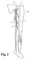
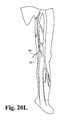
- FIG. 1shown in Figure 1 is a diagram of a human leg showing certain venous structures therein.
- human leg 200having greater saphenous vein 10 and the femoral vein 11 which adjoin at the sapheno-femoral junction 12.
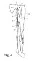
- Devices in accordance with the present inventionmay be used to occlude the greater saphenous vein 10 in a region constituting substantially all of the passage between a point 13 occuring near the medial side of the knee to a point 14 occuring prior to the sapheno-femoral junction 12, as illustrated by the shaded area in Figure 2 .
- such occlusionis effective to prevent reflux of venous blood from the sapheno-femoral junction 12 in a direction down toward the medial side of the knee (e.g. at point 13).
- Such occlusionis effective to treat varicosities that commonly occur in lower portions of the leg, e.g. portions occurring below the knee.
- occlusion of the passage of the greater saphenous vein occurring between points 13 and 14is achieved by an example of an elongate occlusion device 15 that extends from point 13 to point 14, and that may include end portions 16 and 17 that traverse the wall of the greater saphenous vein 10. This may be achieved by deploying occlusion device 15 during a through-and-through percutaneous procedure, e.g. as described hereinbelow. It will be understood, however, that other occlusion devices may be used, including those others disclosed herein.
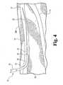
- FIG. 4shown is an enlarged view of that portion of the human leg occurring generally between points 13 and 14 of Figure 1 .
- percutaneous access to the greater saphenous vein 10is achieved at point 13 using the Seldinger or any other suitable technique.
- an access needlecan be passed through the skin to access greater saphenous vein 10
- a wire guide 20can be passed through the access needle and into the vein 10.
- wire guide 20Prior to deployment of an occlusion device, wire guide 20 can be used for any number of conventional procedures including catheterization and imaging procedures in order to locate the sapheno-femoral junction 12 and discern a desired exit point 14 for a through-and-through percutaneous procedure. After any such preliminary procedures that are performed, wire guide 20 can be used in a deployment procedure for an occlusion device.
- an example of deployment assembly 21includes a flexible catheter 22, such as a 5 French radiopaque Teflon catheter, a guide sheath 23, such as a 7 French radiopaque guide sheath, a stiffening cannula received within guide sheath 23 (not shown in Fig. 4 ), and a delivery sheath 24 received over guide sheath 23.
- Guide sheath 23includes a tapered distal end 25 and a bend 26 adjacent the distal end 25, generally corresponding to a bend in the stiffening cannula.
- Deployment assembly 21is preassembled and threaded along guide wire 20 for the deployment procedure.
- deployment assembly 21now received within greater saphenous vein 10 from point 13 to point 14, with the tapered distal end 25 of the guide sheath 23 positioned against the wall of greater saphenous vein 10 using the bend 26 to achieve rotation and placement of the end 25 of the guide sheath 23.
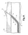
- FIG. 6provide enlarged cross-sectional views in and around exit point 14 of greater saphenous vein 10 and illustrate various stages of a percutaneous exit procedure.
- FIG. 6is a cross-sectional view of the stage of the procedure illustrated in Figure 5 .
- Tapered end 25 of guide sheath 23is shown positioned against the wall of greater saphenous vein 10 at point 14.
- Received immediately within guide sheath 23is stiffening cannula 28, which for example may be made from 14 gauge stainless steel.
- Received immediately within stiffening cannula 28is guide catheter 22; and, received within guide catheter 22 is guide wire 20.
- guide wire 20 and guide catheter 22are withdrawn from the deployment assembly leaving a condition as illustrated in Figure 7 with guide sheath 23 and stiffening cannula 28 remaining in place.
- a guide catheter 30 and long needle 31are threaded through the interior of stiffening cannula 28, and needle 31 is used to penetrate the wall of greater saphenous vein 10 as illustrated.
- Needle 31is advanced through the adjacent tissue toward the surface of the skin. Needle 31 may have a needle point of such a sharpness that the needle does not exit the skin, but rather creates a visible bump 32 in the skin from which the location of the needle 31 can be visibly discerned.
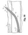
- the skincan be nicked at or near the apex of the bump 32 with a scalpel or other suitable instrument, to allow exit of the needle 31, as illustrated in Figure 9 .
- needle 31is grasped with forceps or any other suitable means and used to pull deployment assembly 21 through the skin with guide sheath 23 and elements internal thereof exiting first, during which tapered end 25 serves as a dilator to ease exit (see Fig. 10 ), and eventually exposing end 34 of delivery sheath 24 externally of the skin (see Fig. 11 ).
- all components except for delivery sheath 24are withdrawn, leaving in place delivery sheath 24 with its internal cannula open 35 (see Fig. 12 ) for use in delivering an occlusion device, for example as described below.
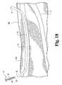
- FIG. 13shown is a diagram including greater saphenous vein 10 from points 13-14, at the same stage of the procedure as that shown in Figure 12 .
- Delivery sheath 24is in place in a through-and-through fashion, having a first end 34 exposed through the skin at point 14 occurring near the groin of the patient adjacent the sapheno-femoral junction, and a second end 36 exposed through the skin adjacent the medial portion of the knee of the patient.
- internal cannula 35 of delivery sheath 24is open and available for use in delivering a vascular occlusion device.
- a relatively stiff guide wire 37can be threaded through delivery sheath 24.
- Guide wire 37has an engaging end 38 including a hooked portion 39 or other suitable adaptation for connection to an example occlusion device 40.
- Occlusion device 40includes a looped structure 41 or any other suitable connection structure at an end thereof. Hooked portion 39 can be connected to looped structure 41, and guide wire 37 can thereafter be used to draw occlusion device 40 through delivery sheath 24, as generally shown in Figure 15 .
- Figure 15illustrates occlusion device 40 having been drawn through delivery sheath 24 to expose an end 27 adjacent looped structure 41 from the skin near the groin of the patient, leaving an end 42 exposed through the skin near the knee of the patient.
- delivery sheath 24can be withdrawn, leaving in place only occlusion device 40 in a through-and-through condition with the first end 27 and the second end 42 remaining external of the skin of the patient (see Figure 16 ). Subsequently, the ends of the occlusion device 40 can be trimmed, and any excess length of device 40 remaining external of the patient can be tucked underneath the skin.
- the percutaneous access and exit sitescan be closed by suturing or any other suitable technique, if necessary.
- a second guide wire 37can be threaded through sheath such that guide wire 37 and device 40 are both received through sheath 24.
- Sheath 24can then be withdrawn, leaving in place device 40 and guide wire 37 each in a through-and-through condition.
- the remaining guide wire 37can then be used to guide a subsequent deployment assembly 21, and the overall procedure repeated one or more times as described above to place a second device 40, a third device 40, etc.
- occlusion device 40 or devices 40Upon being positioned within greater saphenous vein 10, occlusion device 40 or devices 40 restrict blood flow in the greater saphenous vein 10 so as to occlude or exclude the same. It is desired that occlusion device 40 be of such a dimension that the material comprising device 40 substantially blocks the internal lumen of greater saphenous vein 10. To this end, the device 40 can have a compressed condition and be adapted to convert to an altered physical configuration after deployment. For example, all or a portion of device 40 may be adapted to expand, unfold, unroll, untwist, harden, or otherwise progress to a condition other than that which it had during deployment and which aids in occluding the vessel.
- occlusion device 40can cause localized thrombus to cause or assist in occluding the lumen of greater saphenous vein 10.
- expandable occlusion devicescan comprise a porous sponge extracellular matrix (ECM) structure and/or a collagenous foam.
- ECMextracellular matrix
- suitable sponge matrix materials and their preparationreference can be made, for example, to U.S. Pat. No. 6,666,892 and International Publication No. WO03/002168 .
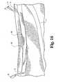
- Occlusion assembly 43includes example occlusion device 44 received within an external cannula such as a sheath 45, for coaxial style delivery through delivery sheath 24.
- sheath 24can be a 12 French sheath and sheath 45 can be a 10 French sheath.
- Sheath 45 or other external cannuladesirably has an elongate slit 46 therein or another opening or openings along its length.
- opening or openingsare beneficial, for example, in that the device 44 can be sterilized after loading within the sheath 45 using gaseous agents such as ethylene oxide (EO) which penetrate through the opening or openings to contact and sterilize device 44.
- gaseous agentssuch as ethylene oxide (EO) which penetrate through the opening or openings to contact and sterilize device 44.
- EOethylene oxide
- occlusion assembly 43is threaded into and through delivery sheath 24 to achieve a through-and-through condition, whereafter sheaths 24 and 45 are withdrawn leaving occlusion device 44 in place in a through-and-through condition as generally described above.
- Device 44can then be trimmed and tucked, and the procedure completed as generally described above.
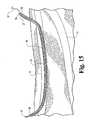
- FIG. 18shown is a view similar to that depicted in Figure 14 , except showing an alternative example occlusion device and delivery system.
- delivery sheath 24is in place in a through-and-through condition.
- An occlusion assembly 47includes an example elongate occlusion device 48 received concentrically around an internal guide member 49, such as a guide wire, and if desired is provided with an end piece 50 with a tapered end to assist in traversal of the occlusion device 48 through the delivery sheath 24.
- an internal guide member 49such as a guide wire
- the assembly 47 including occlusion device 48, guide member 49, and end piece 50has sufficient column strength and integrity to be pushed through delivery sheath 24 from end 36 to end 34, leaving occlusion device 48 in a through-and-through condition. Internal guide member 49 with end piece 50 and sheath 24 can then be withdrawn, and the occlusion device 48 trimmed and tucked prior to completing the procedure as described above.
- Figure 19Aillustrates initial access to a vascular vessel 60 through the skin 61 via introducer needle 62, which is used to deliver guide wire 63 to the vessel 60.
- Guide wire 63is used to guide an assembly including a dilator 64 and an outer sheath 65 into the vessel 60, as shown in Figure 19B .
- the guide wire 63 and dilator 64are withdrawn, leaving in place sheath 65 as shown in Fig. 19C.
- FIG. 19Dshows a stage of the procedure in which a second percutaneous access is provided via introducer needle 66, with the needle 66 penetrating sheath 65.
- a guide wire 68is introduced through needle 66 and traverses sheath 65 thus exiting the initial percutaneous access site.
- sheath 65is withdrawn over guide wire 68 leaving in place guide wire 68 in a through-and-through condition as shown in Fig. 19F .
- An assembly including dilator 69 and sheath 70is then introduced over guide wire 68 as shown in Fig. 19G , and the dilator 69 and guide wire 68 are withdrawn thereby leaving in place sheath 70 in a through-and-through condition as shown in Fig. 19H .
- Sheath 70can then be used for the introduction of an occlusion device in a suitable manner including those described hereinabove.
- FIG. 20Aillustrates an early stage in the procedure wherein access to vascular vessel 70 is provided through skin 71 at two locations.
- introducer needle 72accesses vessel 70 and is used to deliver a "J" guide wire 73 into vessel 70.
- introducer needle 74is used to access vessel 70 and deliver guide wire 75 to vessel 70.
- a catheter 76is advanced over the "J" guide wire 73, and an assembly including catheter 77 and overlying sheath 78 is advanced over guide wire 75.
- catheter 76can optionally have a segment (e.g. about 3 to 10 cm in length) proximal to the distal tip that tapers to a slightly enlarged external diameter.
- Fig. 20Eshows the sheath 78 thereafter established in a through-and-through condition after withdrawal of the catheter 76 and "J" guide wire 73 from the sheath 78. Sheath 78 can then be used for the deployment of an occlusion device in any suitable manner including those described above.
- occlusion devicesAlthough certain exemplary procedures have been described above for the delivery of occlusion devices, it will be understood that other modes of delivery of occlusion devices are suitable in the present invention. For example, procedures involving only a single point of percutaneous access can be conducted, for instance wherein a delivery sheath is established through a percutaneous access site and into the vascular vessel to be occluded, and an occlusion device is delivered from the sheath using any suitable technique including pushing the occlusion device from the end of the sheath, e.g. as the sheath is withdrawn. In situations where needed, techniques and/or device adaptations can be employed to help to prevent withdrawal of the occlusion device as the sheath is being withdrawn from the patient over the occlusion device. These include the use of anchoring portions connected to the occlusion device that forcibly contact vessel walls and resist migration.
- FIGS 20F-20Iis one descending delivery method involving only a single point of access.
- a guide wire 51such as a J-wire is established in the greater saphenous vein via a percutaneous entry 52 near the groin.
- a cannulated device 53such as a catheter or sheath is established in the vein ( Figure 20G ), and an example occluder device 54 is delivered to the vein through the cannulated device 53 ( Figure 20H ), e.g. by pushing or otherwise delivering the occluder device 54 out of the cannulated device 53 and withdrawing the cannulated device 53, potentially in a simultaneous operation.
- the occluder device 54can have a length sufficient to extend from the vein and out of the percutanous exit 52, as shown in Figure 20H .
- the occluder devicecan then be trimmed and if desired secured at the site of percutaneous entry 52 ( Figure 20I ).
- Figures 20J-20Millustrate a similar one-site percutaneous delivery, except using an ascending approach with entry just above the knee.
- the occlusion device 186 in accordance with the inventioncomprises a ribbon or band 172 attached to a fixation device 174, such as a flexible tube or rod, using one or more sutures 180, or other suitable securing means.
- a fixation device 174such as a flexible tube or rod
- sutures 180or other suitable securing means.
- each end of the fixation device 176, 178can terminate with one or more barbs, or other suitable anchoring means.
- the occlusion device 186can be deployed by first locating a deployment sheath 182 in a vascular vessel 170.
- the ribbon 172 portion of the occlusion device 186can be loaded into a delivery sheath 184 while leaving the fixation device 174 external to the distal end 185 of the delivery sheath 184.
- the delivery sheath 184, containing the occlusion device 186can be placed inside the deployment sheath 182 in a manner that compresses or flexes the fixation device 174 and the delivery sheath 184 can be pushed through the deployment sheath 182.
- the fixation device 174breaches the distal end of the deployment sheath 183, it will expand, thereby anchoring itself into the wall of the vessel 170 (see Fig. 200).
- the deployment sheath 182 and delivery sheath 184can be retracted to deploy the ribbon 172 into the vessel (see Fig. 20P ).
- a plurality of occlusion devices 186can be deployed in the same vascular vessel 170 according to the above exemplary method to achieve suitable occlusion and/or thrombosis of the vascular vessel 170.
- the ribbon 172can be folded over and secured to the fixation device 174, thereby forming two legs or bands for achieving occlusion.
- Figures 21 to 35Billustrate various reference embodiments and examples of vascular occlusion devices.
- Fig. 21shows vascular occlusion device 80 having an occlusion body 81, and first end 82, and a second end 83.
- Device 80has a length "L" sufficient to occlude the length of the passage for which occlusion or ablation is desired.
- the device 80may have a length sufficient and may be positioned so as to traverse at least one vessel that branches from the vessel to be occluded, for instance a perforator or communicator vein branching from a larger vein to be occluded such as a saphenous vein, e.g. the greater saphenous vein.
- length "L"will be sufficient to traverse the greater saphenous vein from position 13 to position 14, desirably having sufficient excess length to exit percutaneous access sites at those locations for processing as described.
- Fig. 22shows a reference exemplary occlusion device 84 having an occlusion body 85, with first and second ribbons 86 and 87 of occlusion material. Ribbons 86 and 87 are adjoined to one another integrally by an area 88 of occlusion material.
- Fig. 23shows a reference exemplary occlusion device 89 having an occlusion body 90 with first and second legs or ribbons of material 91 and 92. Ribbons 91 and 92 are formed.by creating a fold 93 in an integral longer sheet of material. If desired, a wire loop 94 or any other suitable tethering adaptation can be positioned around fold 93 or otherwise connected to the occlusion body 90.
- a reference exemplary occlusion device 95having occlusion body 96 with a first end 97 and a second end 98 thereof.
- Occlusion body 96includes a plurality of cuts or slits along the length thereof to form flares or legs 99 which increase the surface area for contact with blood after deployment and enhance the occlusive character of the device 95, e.g. by promoting thrombus.
- Fig. 25shows a reference exemplary occlusion device 100 having a plurality of ribbons 101, 102, 103, and 104 connected by an element 105 such as a wire loop threaded through ends of the ribbons.
- occlusion device 106formed as a roll of occlusion material to provide a generally cylindrical occlusion body 107. Additionally, occlusion body 107 could be partially or completely slit along plane 108 and potentially additional planes, to provide modified configurations having increased surface area for blood contact.
- a reference exemplary occlusion device 109having an occlusion body 110, formed by creating multiple folds 111 in a sheet of occlusion material.
- this folded adaptation and other adaptations described hereincan be designed to render the occlusion devices more compact and less voluminous for delivery, but which devices expand, unfold, or otherwise take on an increased dimension after delivery to facilitate the occlusion function.
- Fig. 28shows a reference exemplary occlusion device 112 having an occlusion body 113 formed as a roll 114 of occlusion material.
- the external surface of occlusion body 113has been contoured to create a plurality of bumps, flares or other protuberances 115 along the length thereof.
- Fig. 29A and 29Billustrate additional reference exemplary occlusion devices.
- Fig. 29Ashows occlusion device 116 having an occlusion body 117 formed of an occlusion material.
- Body 117includes a plurality of cuts or slits 118, for example to provide a mesh configuration, to increase surface area for blood contact. Additionally, occlusion body 117 can be rolled (see arrows) in order to form an alternate occlusion device 119 shown in Figure 29B .
- Device 119includes a generally cylindrical occlusion body 120 having irregular, raised loops or others portions of material 121 flaring from its surface.
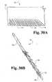
- FIG. 30Ashows an occlusion device 122 including an occlusion body 123 having a plurality of legs or ribbons of material 124 established along an edge thereof by cutting or slitting material. If desired, occlusion body 123 can be rolled diagonally from a corner thereof (see arrows) in order to provide occlusion device 125 illustrated in Fig. 30B .
- Device 125includes a generally cylindrical body 126 and in its rolled configuration ribbons 124 extend or flare from the surface thereof for increased blood contact.
- occlusion materialin any suitable form, such as a ribbon, band, foam, cylinder, or the like, can be combined with elements for anchoring one or both ends of the occlusion device within a vascular vessel.
- a vascular vesselIllustratively, shown in Fig. 31 is an occlusion device 127 having an occlusion body 128 made out of an occlusion material, and an elongate wire or other element 129 received within occlusion body 128. Wire or other element 129 exits the ends of the occlusion body 128, and provides coils 130 and 131 which can be configured to expand and provide points of securement of device 127 within a vascular vessel.
- coils 130 and 131may have synthetic fibers attached thereto to facilitate thrombus formation, for example as conventionally incorporated on commercial platinum or stainless steel embolization and occlusion coils.
- the occlusion body 128is shown in tubular form, it can occupy any suitable shape or form, such as a ribbon, band, foam, or the like.
- occlusion device 132similar to that depicted in Figure 31 , including an occlusion body 133, and an internal wire or other element, and securement adaptations 134 and 135 provided by a plurality of diverging filaments or wire elements such as those found in vascular filters.
- occlusion devices of the inventionincluding occlusion bodies and self-expanding or forcibly (e.g. balloon) expandable stents secured to the ends of the occlusion bodies for providing points of securement within a vascular vessel.
- Fig. 33shows device 136 having occlusion body 137, such as a strip or tube of occlusion material, having first and second square stents 138 and 139 attached to the ends thereof.
- Square-shaped stents 138 and 139can, for example, be constructed as described in U.S. Patent Nos. 6,200,336 and 6,508,833 .
- vascular occlusion device 140having an occlusion body 141 such as a strip or tube of occlusion material having secured at the ends thereof stents such as those ZILVER® stents sold by Cook, Inc., Bloomington, Indiana (elements 142 and 143).
- Fig. 35Ashows an occlusion device 144A having an occlusion body 145A such as a strip or tube of occlusion material having attached to ends thereof Z-stents 146A and 147A such as those sold by Cook, Inc.
- Fig. 35Bdiscloses an occlusion device 144B similar to that depicted in Fig.
- attachment of the occluder material to the anchor devicemay be achieved by suturing, bonding, heat-induced welding (including laser welding), or any other suitable technique.
- any lumen of the stent(s)may be spanned and closed by a biomaterial, including a remodelable biomaterial as described herein, to facilitate the occlusion procedure.
- the material used in the formation of vascular occlusion devices of the inventioncan be any material suitable for occluding a vascular vessel of interest.
- the occluder body of the occlusion device in accordance with the inventioncomprises an extracellular matrix material.
- Bioremodelable materialsmay be used in this context to promote cellular growth within the lumen of the occluded vessel. This helps to guard against reestablishment of patency of the vessel through biologic processes after the occlusion procedure is completed.
- Suitable bioremodelable materialscan be provided by collagenous extracellular matrix materials (ECMs) possessing biotropic properties. These can be delivered to the vessel in a lyophilized or otherwise dried, or hydrated state, or additionally or alternatively in a gel or otherwise flowable (and optionally hardenable) state.
- ECMsinclude submucosa, renal capsule membrane, dermal collagen, dura mater, pericardium, serosa, peritoneum or basement membrane layers, including liver basement membrane.
- Suitable submucosa materials for these purposesinclude, for instance, intestinal submucosa including small intestinal submucosa, stomach submucosa, urinary bladder submucosa, and uterine submucosa.
- the submucosa material and any other ECM usedmay optionally retain growth factors or other bioactive components native to the source tissue.
- the submucosa or other ECMmay include one or more growth factors such as basic fibroblast growth factor (FGF-2), transforming growth factor beta (TGF-beta), epidermal growth factor (EGF), and/or platelet derived growth factor (PDGF).
- FGF-2basic fibroblast growth factor
- TGF-betatransforming growth factor beta
- EGFepidermal growth factor
- PDGFplatelet derived growth factor
- submucosa or other ECM used in the inventionmay include other biological materials such as heparin, heparin sulfate, hyaluronic acid, fibronectin and the like.
- the submucosa or other ECM materialmay include a bioactive component that induces, directly or indirectly, a cellular response such as a change in cell morphology, proliferation, growth, protein or gene expression.
- non-native bioactive componentssuch as those synthetically produced by recombinant technology or other methods, may be incorporated into the submucosa tissue.
- These non-native bioactive componentsmay be naturally-derived or recombinantly produced proteins that correspond to those natively occuring in the ECM tissue, but perhaps of a different species (e.g. human proteins applied to collagenous ECMs from other animals, such as pigs).
- the non-native bioactive componentsmay also be drug substances.
- Illustrative drug substances that may be incorporated into and/or onto the occlusion devicesinclude, for example, antibiotics, thrombus-promoting substances such as blood clotting factors, e.g.
- thrombinthrombin, fibrinogen, and the like.
- These substancesmay be applied to the occlusion device as a premanufactured step, immediately prior to the procedure (e.g. by soaking the material in a solution containing a suitable antibiotic such as cefazolin), or during or after deployment of the occlusion device in the patient.
- Submucosa or other ECM tissue used in the inventionis preferably highly purified, for example, as described in U.S. Patent No. 6,206,931 to Cook et al.
- preferred ECM materialwill exhibit an endotoxin level of less than about 12 endotoxin units (EU) per gram, more preferably less than about 5 EU per gram, and most preferably less than about 1 EU per gram.
- EUendotoxin units
- the submucosa or other ECM materialmay have a bioburden of less than about 1 colony forming units (CFU) per gram, more preferably less than about 0.5 CFU per gram.
- CFUcolony forming units
- Fungus levelsare desirably similarly low, for example less than about 1 CFU per gram, more preferably less than about 0.5 CFU per gram.
- Nucleic acid levelsare preferably less than about 5 ⁇ g/mg, more preferably less than about 2 ⁇ g/mg, and virus levels are preferably less than about 50 plaque forming units (PFU) per gram, more preferably less than about 5 PFU per gram.
- the ECM material used in the inventionis preferably disinfected with an oxidizing agent, particularly a peracid, such as peracetic acid.
- ECMscan be in a hydrated or dried state in the product as packaged and/or when delivered. Suitable drying techniques include, for example, air drying, lyophilization techniques including freeze-drying and evaporative cooling, and vacuum-drying e.g. as occurs in vacuum pressing processes.
- occluder devices of the inventioninclude ECM materials, a portion of which have been dried by one technique and another portion of which have been dried by another, differing technique.
- an occluder devicemay be provided with a more pliant portion that has been dried under lyophilization conditions, and a less pliant portion that has been dried by air-drying or under vacuum pressing conditions.
- a reference exemplary occluder device 150that includes a relatively pliant, lyophilized, fan-folded portion 151 attached at one end to a more rigid vacuum-pressed portion 152 which may be formed as a cord or rope.
- the device 150can be advanced into a vein or other vessel (e.g. from a sheath or other cannulated device) with the fan-folded portion 151 as the leading end, while using the more rigid vacuum-pressed portion 152 to push the fan-folded portion 151.
- the vacuum-pressed portion 152can optionally be sufficiently long to extend out of the percutaneous entry site and effectively serve as a pusher rod. After withdrawal of the sheath, the vacuum-pressed portion can be trimmed at the skin and tucked into the percutaneous access site.
- FIG 37shows another reference exemplary occluder device including a collagenous material such as an ECM, and a more rigid component.
- Occluder device 153includes an elongate body 154 of ECM or other collagenous material, and a more rigid elongate element 155 connected to the body 154.
- element 155can be connected to the body 154 at least at or near the distal end 156 of the body 154, which will serve as the leading end of the device 153 during delivery, e.g. from a sheath or other cannulated device.
- Element 155may be connected to body 154 at multiple points or continuously along the length of body 154.
- Element 155can have a length sufficient to extend from the cannulated device.
- element 155can be held in place during withdrawal of the cannulated device, to facilitate maintaining the position of the distal end 156 of body 154 in the vein or other vessel during such withdrawal.
- a splitable sheath or other cannulated devicecan be employed during delivery, and split around rigid element 155 as the sheath is withdrawn from the patient.
- element 155is made from a permanently implantable material, element 155 can be trimmed and left implanted in the patient along with body 154.
- element 155may be comprised of a bioresorbable and/or bioremodelable material such as a synthetic polymer or collagen, including an ECM material.
- element 155 and body 154each comprise an ECM such as submucosa or another collagenous material
- element 155may for example be air-dried or vacuum pressed to be more rigid than body 154, which may be lyophilized.
- element 155 and body 154may be formed of a single piece of material, or multiple pieces of material attached together, e.g. by bonding or suturing with a bioresorbable or other material.
- Distal anchoring end 159is configured to expand and contact the walls of the vein or other vessel after delivery from the end of a cannulated device, sufficiently to facilitate maintaining the end 159 and connected body 158 in place during withdrawal of the cannulated device.
- Distal anchoring end 159may be made from the same material or a different material as elongate body 158.
- body 158 and distal anchoring end 159may both be made of an ECM such as submucosa, with anchoring end 159 being comprised of a relatively highly expandable porous material such as sponge or foam, and body 158 being comprised of a less expandable ribbon.
- the anchoring end 159 and body 158may for example be integrally formed, or may be separate pieces attached to one another by bonding, sutures or other means.
- the ribbon or other body 158may be sufficiently long to extend to the percutaneous exit site, where it can be trimmed after delivery.
- an anchoring end 159Ais provided by a coiled portion that is collapsed during receipt within the cannulated delivery device, and which radially expands upon exiting the device.
- the materialcan be lyophilized, vacuum-pressed or otherwise dried in the coiled or other radially-expanding configuration, to set a shape memory to the material.
- devices 157 and 157Amay be delivered in a dual-sheath system 160, in which an inner sheath 161 extends to the trailing edge 162 of the anchoring end 159,159A, and an outer sheath 163 extends over the anchoring end 159,159A.
- outer sheath 163can be withdrawn to release anchoring end 159,159A to expand and contact the vessel walls, whereafter inner sheath 161 can be withdrawn while anchoring end 159,159A resists withdrawal of the device 157,157A from the vessel.
- a dual-sheath systemmay be used in conjunction with any similar occluder device having an expandable anchoring feature and an elongate portion, including expandable features such as stents, filter-type baskets, coils, and the like.
- devices similar to those shown in Figures 38 and 39except having more than one anchoring portion, e.g. having anchoring ends at both ends, are also contemplated as being within the invention.
- Such devices having an anchoring portion at each endmay be deployed fully into the lumen of the vein or other vessel to be occluded, with the anchoring ends contacting the vessel walls and stabilizing the position of the devices in the vessel.
- Occlusion devices of the inventionwill generally be of sufficient dimension to achieve occlusion of the desired stretch of vascular vessel, either alone or in combination with other similar or differing devices.
- the occluder body of the occlusion device in accordance with the inventionwill have a length of at least about 10 cm, and in many situations at least about 20 cm. Indeed, for preferred occlusion procedures involving a significant stretch of an artery or vein, occlusion devices having bodies with lengths greater than 30 cm will be used.
- occlusion devices having bodies with lengths of at least about 40 cm or 50 cmcan be used.
- the greater saphenous veinmay also be accessed at a lower level, e.g. near the ankle. During such access, any or all of the greater saphenous vein occurring between the ankle and the sapheno-femoral junction may be subjected to occlusion.
- Other veins in the leg(s) that may be involved in the varicose vein conditionmay also be occluded, alternatively or in addition to the greater saphenous vein.
- the lesser saphenous vein, or varicose veins themselvesmay be occluded and obliterated using occlusion devices in accordance with the invention.
- other veins or arteries in the leg(s) or elsewhere in the bodymay be occluded using occlusion devices in accordance with the present invention.
- Percutaneously-conducted occlusion procedureswill typically be performed under local anesthesia.
- it may be beneficial to use graduated compression stockings in the occluded areafor example for a week or more. Compression of the occluded area may serve to facilitate permanent closure of the occluded vessel, for example when applied during a remodeling period during which tissue ingrowth into the occluded lumen occurs.
- Sheaths, dilator, wire guides and needles used in the exemplary procedures disclosedcan all be conventional marketed products or modifications thereof.
- sheathscan be formed from PTFE (e.g. Teflon) or polyamide (e.g. Nylon) material, or a combination of materials such as an assembly including an inner layer of PTFE, a flat wire coil over the PTFE for kink resistance, and a polyamide (Nylon) outer layer to provide integrity to the overall structure and a smooth surface (e.g. as in the Flexor sheath, Cook, Inc.).
- Dilatorscan be made from conventional dilator/catheter type materials such as polyethylene, polyamide, polyurethane or vinyl, or any combination of these materials.
- Fittings provided for sheath/dilator assembliescan be conventional elements such as luer locks, and the dilator can have a fitting allowing it to be locked to the sheath during insertion and manipulation.
- Catheterscan be made from conventional materials such as polyethylene, polyamide, PTFE, polyurethane, and other materials.
- Delivery sheaths used in the exemplary procedures disclosedwill have a lumen diameter sized to allow for the introduction of a sufficient amount of occlusion material to occlude the artery or vein of interest.
- the inner diameter (I.D.) of the final delivery sheathcan range from about 8 French up to about 40 French.
- the distal ends of the catheters, sheaths, dilators, wires or other components used in percutaneous procedurescan include markers that can be X-ray, sonographically, or otherwise non-invasively visualized to identify their location during the procedure.
- Metallic bands of stainless steel, tantalum, platinum, gold, or other suitable materials, which include a dimple pattern,can serve the purpose for both ultrasound and X-ray identification.
- distal and/or proximal ends and/or other locations on occluder devices of the inventionmay include markers for non-invasive imaging, including imageable materials such as those discussed above as well as substances that can be applied to ECMs, e.g. substances containing tantalum, barium, iodine, or bismuth, e.g. in powder form.
- the inventionalso encompasses medical kits, such as, for example, an elongate puncture device, a cannulated guiding device, a sheath, a guide wire configured for engagement of an occlusion device, and an inventive occlusion device, that may be sealed within sterile medical packaging.
- the final, packaged productsmay be provided in a sterile condition. This may be achieved, for example, by gamma, e.-beam or other irradiation techniques, ethylene oxide gas, or any other suitable sterilization technique, and the materials and other properties of the medical packaging will be selected accordingly.
- the occlusion devicemay be packaged wet or after it is dried.
Landscapes
- Health & Medical Sciences (AREA)
- Surgery (AREA)
- Life Sciences & Earth Sciences (AREA)
- Heart & Thoracic Surgery (AREA)
- Molecular Biology (AREA)
- Vascular Medicine (AREA)
- Engineering & Computer Science (AREA)
- Biomedical Technology (AREA)
- Reproductive Health (AREA)
- Medical Informatics (AREA)
- Nuclear Medicine, Radiotherapy & Molecular Imaging (AREA)
- Animal Behavior & Ethology (AREA)
- General Health & Medical Sciences (AREA)
- Public Health (AREA)
- Veterinary Medicine (AREA)
- Surgical Instruments (AREA)
- Medicines Containing Plant Substances (AREA)
- Materials For Medical Uses (AREA)
- Prostheses (AREA)
Description
- The present invention resides generally in the field of devices useful for the occlusion of vascular vessels, and in a particular aspect relates to devices for the occlusion of the greater or lessor saphenous vein to treat complications, such as varicose vein condition, resultant of venous reflux.
- As further background, the human venous system generally includes a superficial venous system and a deep venous system, with perforating veins connecting the two systems. In human legs, the superficial system includes the great saphenous vein and the short saphenous vein. The deep system of the legs includes the anterior and posterior tibial veins which join to form the popliteal vein, which becomes the femoral vein when united with the short saphenous vein.
- Such venous systems are designed to carry blood back to the heart. To facilitate this function, the venous systems contain one-way valves, which are typically bicuspid. The failure of venous valves leads to retrograde flow or reflux within the venous system. This can result in various venous diseases which include varicose veins and chronic venous insufficiency. In the varicose vein condition, the superficial veins of the leg become dilated and tortuous and can result in discoloration, pain and ulceration. The varicose vein condition commonly involves the incompetence of one or more venous valves which allow reflux of blood from the deep venous system to the superficial venous system or reflux within the superficial system. In many cases, blood from the deep vein system refluxes back down the greater saphenous vein leading to varicosity within superficial veins below the greater saphenous vein.
- Surgical stripping of the greater saphenous vein is an extensively practiced technique for treating the varicose vein condition. In this technique, an incision is made in the groin to expose the sapheno-femoral junction, where the great saphenous vein and its branches are ligated. The distal portion of the greater saphenous vein has been exposed by incision interior to the medial inalleolus, and a stripping device is introduced to exit from the proximal saphenous vein. After holding the leg vertical for a time to empty the venous tree, the vein is stripped from the ankle to the groin. In cases wherein the small saphenous vein is also incompetent, it is stripped at the same time from an incision posterior to the lateral malleolus to the popliteal space. After stripping, the leg is held vertically for a time to permit vessel ends to retract, constrict and clot. The stripping procedure is commonly followed by the removal of collateral veins working through small incisions using an avulsion-extraction technique.
- More recently, techniques have been developed to try to avoid the invasive stripping procedure and its associated complications. For example, techniques and devices have been developed to treat the varicose vein condition with radiofrequency (RF) energy. In these techniques a catheter having an electrode tip is used to deliver RF energy within the vein to be treated. The RF energy causes localized heating and shrinkage of the venous tissue. The electrodes can be drawn through or repositioned within the vein to treat different sections or segments of the vein. For additional information on RF treatments and devices, reference can be made for example to
US Patent Nos. 6,200,312 ,6,179,832 ,6,165,172 ,6,152,899 ,6,071,277 ,6,036,687 ,6,033,398 ,6,014,589 , and5,609,598 . - Another technique which has been developed is the endovenous laser technique. This technique is typically performed under local or regional anesthesia. A bare laser fiber is inserted into the diseased vein and delivers laser light in a pulsed fashion to heat the vein to cause damage and constriction. See, e.g.,Gorisch et al., "Heat Induced Contraction of Blood Vessels", Laser Surgery Medicine 2(1), 1-13(1982). Other techniques for treating the varicose vein condition includes sclerotherapy, in which a sclerosing solution is injected into the vein to damage the interior of the vein, followed by compression wrapping to facilitate permanent closure of the damaged vein. Phlebectomy is a procedure also utilized to treat varicose veins, typically medium sized and larger veins. In this procedure, small stab incisions are made in the skin and a tool is used to hook and pull the vein out through the incision.
WO 03/043506 WO 03/009764 WO 00/45691 WO 01/70091 - In view of this background, the need remains for improved and alternative devices for affecting the venous system to treat venous conditions. The present invention is addressed to these needs.
- According to a first aspect of the present invention there is provided an occlusion device useful for occluding a vascular vessel of a human according to claim 1.
- Preferred embodiments of the occlusion device are defined in claims 2 to 9 and 11 to 26.
- According to a second aspect of the present invention there is provided a medical kit for vascular occlusion according to
claim 10. - The present invention provides improved devices for occluding venous and other vascular vessels. Additional embodiments as well as features and advantages of the invention will be apparent from the further descriptions herein.
FIG. 1 depicts a human leg showing certain venous structures therein.FIG. 2 depicts a human leg showing certain venous structures therein.FIG. 3 depicts an illustrative configuration of a human leg having an occlusion device located in the greater saphenous vein.FIG. 4 depicts an illustrative deployment system in that portion of the human leg occurring generally betweenpoints FIG. 1 .FIG. 5 depicts an illustrative deployment system in that portion of the human leg occurring generally betweenpoints FIG. 1 .FIG. 6 depicts an illustrative deployment method.FIG. 7 depicts an illustrative deployment method.FIG. 8 depicts an illustrative deployment method.FIG. 9 depicts an illustrative deployment method.FIG. 10 depicts an illustrative deployment method.FIG. 11 depicts an illustrative deployment method.FIG. 12 depicts an illustrative deployment method.FIG. 13 depicts an illustrative deployment system in that portion of the human leg occurring generally betweenpoints FIG. 1 .FIG. 14 depicts an illustrative deployment system in that portion of the human leg occurring generally betweenpoints FIG. 1 .FIG. 15 depicts an illustrative deployment system in that portion of the human leg occurring generally betweenpoints FIG. 1 .FIG. 16 depicts a reference configuration of vascular occlusion device in an illustrative deployment system.FIG. 17 depicts an illustrative deployment system in that portion of the human leg occurring generally betweenpoints FIG. 1 .FIG. 18 depicts an illustrative deployment system in that portion of the human leg occurring generally betweenpoints FIG. 1 .FIGS. 19A-19H depict an illustrative deployment system.FIGS. 20A-20E depict an illustrative deployment system.FIGS. 20F-20I depict an illustrative deployment system.FIGS. 20J-20M depict an illustrative deployment system.FIGS. 20N-20P depict an illustrative occlusion device and an illustrative deployment embodiment of the invention.FIG. 21 depicts a reference exemplary occlusion device.FIG. 22 depicts a reference exemplary occlusion device.FIG. 23 depicts a reference exemplary occlusion device.FIG. 24 depicts a reference exemplary occlusion device.FIG. 25 depicts a reference exemplary occlusion device.FIG. 26 depicts a reference exemplary occlusion device.FIG. 27 depicts a reference exemplary occlusion device.FIG. 28 depicts a reference exemplary occlusion device.FIG. 29A depicts a reference exemplary occlusion device.FIG. 29B depicts a reference exemplary occlusion device.FIG. 30A depicts a reference exemplary occlusion device.FIG. 30B depicts a reference exemplary occlusion device.FIG. 31 depicts an illustrative occlusion device of the invention.FIG. 32 depicts an illustrative occlusion device of the invention.FIG. 33 depicts an illustrative occlusion device of the invention.FIG. 34 depicts an illustrative occlusion device of the invention.FIG. 35A depicts an illustrative occlusion device of the invention.FIG. 35B depicts an illustrative occlusion device of the invention.FIG. 36 depicts a reference exemplary occlusion device.FIG. 37 depicts a reference exemplary occlusion device.FIG. 38 depicts an illustrative occlusion device pf the invention.FIG. 39 depicts an illustrative occlusion device of the invention.FIG. 40 depicts an illustrative deployment of an occlusion device of the invention.- For the purposes of promoting an understanding of the principles of the invention, reference will now be made to the embodiments and examples illustrated in the drawings and specific language will be used to describe the same. It will nevertheless be understood that no limitation of the scope of the invention is thereby intended, and alterations and modifications in the illustrated devices, and further applications of the principles of the invention as illustrated therein are herein contemplated as would normally occur to one skilled in the art to which the invention relates that come within the scope of the appended claims.
- As disclosed above, the present invention provides devices for achieving occlusion of a vascular vessel such as a saphenous vein. Devices of the invention can be used in methods performed, for instance, in order to treat venous reflux through the greater saphenous vein such as that involved in the varicose vein condition.
- With reference now more particularly to the figures, shown in
Figure 1 is a diagram of a human leg showing certain venous structures therein. In particular, shown ishuman leg 200 having greatersaphenous vein 10 and thefemoral vein 11 which adjoin at the sapheno-femoral junction 12. Devices in accordance with the present invention may be used to occlude the greatersaphenous vein 10 in a region constituting substantially all of the passage between apoint 13 occuring near the medial side of the knee to apoint 14 occuring prior to the sapheno-femoral junction 12, as illustrated by the shaded area inFigure 2 . Desirably, such occlusion is effective to prevent reflux of venous blood from the sapheno-femoral junction 12 in a direction down toward the medial side of the knee (e.g. at point 13). Such occlusion is effective to treat varicosities that commonly occur in lower portions of the leg, e.g. portions occurring below the knee. - With reference now to
Figure 3 , occlusion of the passage of the greater saphenous vein occurring betweenpoints elongate occlusion device 15 that extends frompoint 13 to point 14, and that may includeend portions saphenous vein 10. This may be achieved by deployingocclusion device 15 during a through-and-through percutaneous procedure, e.g. as described hereinbelow. It will be understood, however, that other occlusion devices may be used, including those others disclosed herein. - With reference now to
Figure 4 , shown is an enlarged view of that portion of the human leg occurring generally betweenpoints Figure 1 . In an illustrative deployment procedure, percutaneous access to the greatersaphenous vein 10 is achieved atpoint 13 using the Seldinger or any other suitable technique. For instance, an access needle can be passed through the skin to access greatersaphenous vein 10, and awire guide 20 can be passed through the access needle and into thevein 10. Prior to deployment of an occlusion device, wire guide 20 can be used for any number of conventional procedures including catheterization and imaging procedures in order to locate the sapheno-femoral junction 12 and discern a desiredexit point 14 for a through-and-through percutaneous procedure. After any such preliminary procedures that are performed, wire guide 20 can be used in a deployment procedure for an occlusion device. - Specifically, referring still to
Figure 4 , an example ofdeployment assembly 21 includes aflexible catheter 22, such as a 5 French radiopaque Teflon catheter, aguide sheath 23, such as a 7 French radiopaque guide sheath, a stiffening cannula received within guide sheath 23 (not shown inFig. 4 ), and adelivery sheath 24 received overguide sheath 23.Guide sheath 23 includes a tapereddistal end 25 and abend 26 adjacent thedistal end 25, generally corresponding to a bend in the stiffening cannula.Deployment assembly 21 is preassembled and threaded alongguide wire 20 for the deployment procedure. - With reference now to
Figure 5 , shown isdeployment assembly 21 now received within greatersaphenous vein 10 frompoint 13 to point 14, with the tapereddistal end 25 of theguide sheath 23 positioned against the wall of greatersaphenous vein 10 using thebend 26 to achieve rotation and placement of theend 25 of theguide sheath 23. - Reference will now be made to
Figure 6-12 , which provide enlarged cross-sectional views in and aroundexit point 14 of greatersaphenous vein 10 and illustrate various stages of a percutaneous exit procedure. Particularly, shown inFigure 6 is a cross-sectional view of the stage of the procedure illustrated inFigure 5 .Tapered end 25 ofguide sheath 23 is shown positioned against the wall of greatersaphenous vein 10 atpoint 14. Received immediately withinguide sheath 23 is stiffeningcannula 28, which for example may be made from 14 gauge stainless steel. Received immediately within stiffeningcannula 28 isguide catheter 22; and, received withinguide catheter 22 isguide wire 20. In a next stage of the procedure,guide wire 20 and guidecatheter 22 are withdrawn from the deployment assembly leaving a condition as illustrated inFigure 7 withguide sheath 23 and stiffeningcannula 28 remaining in place. - With reference now to
Figure 8 , aguide catheter 30 andlong needle 31 are threaded through the interior of stiffeningcannula 28, andneedle 31 is used to penetrate the wall of greatersaphenous vein 10 as illustrated.Needle 31 is advanced through the adjacent tissue toward the surface of the skin.Needle 31 may have a needle point of such a sharpness that the needle does not exit the skin, but rather creates avisible bump 32 in the skin from which the location of theneedle 31 can be visibly discerned. The skin can be nicked at or near the apex of thebump 32 with a scalpel or other suitable instrument, to allow exit of theneedle 31, as illustrated inFigure 9 . Subsequently,needle 31 is grasped with forceps or any other suitable means and used to pulldeployment assembly 21 through the skin withguide sheath 23 and elements internal thereof exiting first, during whichtapered end 25 serves as a dilator to ease exit (seeFig. 10 ), and eventually exposingend 34 ofdelivery sheath 24 externally of the skin (seeFig. 11 ). Subsequently, all components except fordelivery sheath 24 are withdrawn, leaving inplace delivery sheath 24 with its internal cannula open 35 (seeFig. 12 ) for use in delivering an occlusion device, for example as described below. - With reference now to
Figure 13 shown is a diagram including greatersaphenous vein 10 from points 13-14, at the same stage of the procedure as that shown inFigure 12 .Delivery sheath 24 is in place in a through-and-through fashion, having afirst end 34 exposed through the skin atpoint 14 occurring near the groin of the patient adjacent the sapheno-femoral junction, and asecond end 36 exposed through the skin adjacent the medial portion of the knee of the patient. In this fashion,internal cannula 35 ofdelivery sheath 24 is open and available for use in delivering a vascular occlusion device. - Referring now to
Figure 14 , a relativelystiff guide wire 37 can be threaded throughdelivery sheath 24.Guide wire 37 has anengaging end 38 including a hookedportion 39 or other suitable adaptation for connection to anexample occlusion device 40.Occlusion device 40 includes a loopedstructure 41 or any other suitable connection structure at an end thereof.Hooked portion 39 can be connected to loopedstructure 41, and guidewire 37 can thereafter be used to drawocclusion device 40 throughdelivery sheath 24, as generally shown inFigure 15 . In particular,Figure 15 illustratesocclusion device 40 having been drawn throughdelivery sheath 24 to expose anend 27 adjacent loopedstructure 41 from the skin near the groin of the patient, leaving anend 42 exposed through the skin near the knee of the patient. After this,delivery sheath 24 can be withdrawn, leaving in place onlyocclusion device 40 in a through-and-through condition with thefirst end 27 and thesecond end 42 remaining external of the skin of the patient (seeFigure 16 ). Subsequently, the ends of theocclusion device 40 can be trimmed, and any excess length ofdevice 40 remaining external of the patient can be tucked underneath the skin. The percutaneous access and exit sites can be closed by suturing or any other suitable technique, if necessary. - In some cases, it may be desirable to place more than one
occlusion device 40 within the greatersaphenous vein 10 of the patient. With reference again toFigures 14-15 , if such is desired, more than oneguide wire 37 may be passed throughdelivery sheath 24 to pull through a corresponding number ofdevices 40, or alternatively, sequential passes can be made of one ormore guide wires 37 in order to pulladditional devices 40 through the sheath. On the other hand, ifsheath 24 has insufficient internal diameter to accommodate more than onedevice 40 at a time, again referring toFigure 15 , at this stage, asecond guide wire 37 can be threaded through sheath such thatguide wire 37 anddevice 40 are both received throughsheath 24.Sheath 24 can then be withdrawn, leaving inplace device 40 andguide wire 37 each in a through-and-through condition. The remainingguide wire 37 can then be used to guide asubsequent deployment assembly 21, and the overall procedure repeated one or more times as described above to place asecond device 40, athird device 40, etc. - Upon being positioned within greater
saphenous vein 10,occlusion device 40 ordevices 40 restrict blood flow in the greatersaphenous vein 10 so as to occlude or exclude the same. It is desired thatocclusion device 40 be of such a dimension that thematerial comprising device 40 substantially blocks the internal lumen of greatersaphenous vein 10. To this end, thedevice 40 can have a compressed condition and be adapted to convert to an altered physical configuration after deployment. For example, all or a portion ofdevice 40 may be adapted to expand, unfold, unroll, untwist, harden, or otherwise progress to a condition other than that which it had during deployment and which aids in occluding the vessel. Alternatively or in addition,occlusion device 40 can cause localized thrombus to cause or assist in occluding the lumen of greatersaphenous vein 10. Illustrative such expandable occlusion devices can comprise a porous sponge extracellular matrix (ECM) structure and/or a collagenous foam. For additional information concerning suitable sponge matrix materials and their preparation, reference can be made, for example, toU.S. Pat. No. 6,666,892 and International Publication No.WO03/002168 - With reference now to
Figure 17 , shown is another view similar to that depicted inFigure 14 , except illustrating an alternative technique for delivering an occlusion device.Occlusion assembly 43 includesexample occlusion device 44 received within an external cannula such as asheath 45, for coaxial style delivery throughdelivery sheath 24. For these purposes, illustratively,sheath 24 can be a 12 French sheath andsheath 45 can be a 10 French sheath.Sheath 45 or other external cannula desirably has anelongate slit 46 therein or another opening or openings along its length. Such opening or openings are beneficial, for example, in that thedevice 44 can be sterilized after loading within thesheath 45 using gaseous agents such as ethylene oxide (EO) which penetrate through the opening or openings to contact and sterilizedevice 44. Procedurally,occlusion assembly 43 is threaded into and throughdelivery sheath 24 to achieve a through-and-through condition, whereaftersheaths occlusion device 44 in place in a through-and-through condition as generally described above.Device 44 can then be trimmed and tucked, and the procedure completed as generally described above. - With reference now to
Figure 18 , shown is a view similar to that depicted inFigure 14 , except showing an alternative example occlusion device and delivery system. Particularly,delivery sheath 24 is in place in a through-and-through condition. Anocclusion assembly 47 includes an exampleelongate occlusion device 48 received concentrically around aninternal guide member 49, such as a guide wire, and if desired is provided with anend piece 50 with a tapered end to assist in traversal of theocclusion device 48 through thedelivery sheath 24. Theassembly 47 includingocclusion device 48,guide member 49, andend piece 50 has sufficient column strength and integrity to be pushed throughdelivery sheath 24 fromend 36 to end 34, leavingocclusion device 48 in a through-and-through condition.Internal guide member 49 withend piece 50 andsheath 24 can then be withdrawn, and theocclusion device 48 trimmed and tucked prior to completing the procedure as described above. - With reference to
Figures 19 and20 , illustrated are alternative exemplary methods for delivering example occlusion devices by through-and-through percutaneous procedures. Taking firstFigure 19 ,Figure 19A illustrates initial access to avascular vessel 60 through theskin 61 viaintroducer needle 62, which is used to deliverguide wire 63 to thevessel 60.Guide wire 63 is used to guide an assembly including adilator 64 and anouter sheath 65 into thevessel 60, as shown inFigure 19B . Theguide wire 63 anddilator 64 are withdrawn, leaving inplace sheath 65 as shown inFig. 19C. Fig. 19D shows a stage of the procedure in which a second percutaneous access is provided viaintroducer needle 66, with theneedle 66 penetratingsheath 65. Aguide wire 68 is introduced throughneedle 66 and traversessheath 65 thus exiting the initial percutaneous access site. As shown inFig. 19E ,sheath 65 is withdrawn overguide wire 68 leaving inplace guide wire 68 in a through-and-through condition as shown inFig. 19F . Anassembly including dilator 69 andsheath 70 is then introduced overguide wire 68 as shown inFig. 19G , and thedilator 69 andguide wire 68 are withdrawn thereby leaving inplace sheath 70 in a through-and-through condition as shown inFig. 19H .Sheath 70 can then be used for the introduction of an occlusion device in a suitable manner including those described hereinabove. - With reference now to
Figs. 20A-20E , shown is an alternative procedure for establishing a through-and-through sheath for delivery of an occlusion device.Fig. 20A illustrates an early stage in the procedure wherein access tovascular vessel 70 is provided throughskin 71 at two locations. At a first location,introducer needle 72accesses vessel 70 and is used to deliver a "J"guide wire 73 intovessel 70. At another location,introducer needle 74 is used to accessvessel 70 and deliverguide wire 75 tovessel 70. As illustrated inFig. 20B , acatheter 76 is advanced over the "J"guide wire 73, and anassembly including catheter 77 and overlyingsheath 78 is advanced overguide wire 75. After introduction of thesheath 78 intovessel 70,guide wire 75 andcatheter 77 are withdrawn fromsheath 78. At this stage, as illustrated inFig. 20C , "J"guide wire 73 and its accompanyingcatheter 76 are advanced into the cannula ofsheath 78. Advancement is continued untilcatheter 76 and "J"guide wire 73 exit the opposite end ofsheath 78 as shown inFig. 20D .Catheter 76 can optionally have a segment (e.g. about 3 to 10 cm in length) proximal to the distal tip that tapers to a slightly enlarged external diameter. This segment would fit snugly into thesheath 78, and would create a transitioning external diameter that would ease exit of thesheath 78 from the second puncture site.Fig. 20E shows thesheath 78 thereafter established in a through-and-through condition after withdrawal of thecatheter 76 and "J"guide wire 73 from thesheath 78.Sheath 78 can then be used for the deployment of an occlusion device in any suitable manner including those described above. - Although certain exemplary procedures have been described above for the delivery of occlusion devices, it will be understood that other modes of delivery of occlusion devices are suitable in the present invention. For example, procedures involving only a single point of percutaneous access can be conducted, for instance wherein a delivery sheath is established through a percutaneous access site and into the vascular vessel to be occluded, and an occlusion device is delivered from the sheath using any suitable technique including pushing the occlusion device from the end of the sheath, e.g. as the sheath is withdrawn. In situations where needed, techniques and/or device adaptations can be employed to help to prevent withdrawal of the occlusion device as the sheath is being withdrawn from the patient over the occlusion device. These include the use of anchoring portions connected to the occlusion device that forcibly contact vessel walls and resist migration.
- To illustrate further exemplary percutaneous delivery methods, shown in
Figures 20F-20I is one descending delivery method involving only a single point of access. As shown inFigure 20F , aguide wire 51 such as a J-wire is established in the greater saphenous vein via apercutaneous entry 52 near the groin. Subsequently, using thewire 51, a cannulateddevice 53 such as a catheter or sheath is established in the vein (Figure 20G ), and anexample occluder device 54 is delivered to the vein through the cannulated device 53 (Figure 20H ), e.g. by pushing or otherwise delivering theoccluder device 54 out of the cannulateddevice 53 and withdrawing the cannulateddevice 53, potentially in a simultaneous operation. In one mode of practice, theoccluder device 54 can have a length sufficient to extend from the vein and out of thepercutanous exit 52, as shown inFigure 20H . The occluder device can then be trimmed and if desired secured at the site of percutaneous entry 52 (Figure 20I ).Figures 20J-20M illustrate a similar one-site percutaneous delivery, except using an ascending approach with entry just above the knee. - To illustrate an exemplary percutaneous delivery methods and occlusion devices, shown in
Figures 20N-20P is an occlusion device in accordance with the invention utilizing a single point of access. In this embodiment, turning toFigure 20N , theocclusion device 186 in accordance with the invention comprises a ribbon orband 172 attached to afixation device 174, such as a flexible tube or rod, using one ormore sutures 180, or other suitable securing means. Optionally, each end of thefixation device occlusion device 186 can be deployed by first locating adeployment sheath 182 in avascular vessel 170. Next, theribbon 172 portion of theocclusion device 186 can be loaded into adelivery sheath 184 while leaving thefixation device 174 external to thedistal end 185 of thedelivery sheath 184. Next, thedelivery sheath 184, containing theocclusion device 186, can be placed inside thedeployment sheath 182 in a manner that compresses or flexes thefixation device 174 and thedelivery sheath 184 can be pushed through thedeployment sheath 182. As thefixation device 174 breaches the distal end of thedeployment sheath 183, it will expand, thereby anchoring itself into the wall of the vessel 170 (see Fig. 200). After thefixation device 174 anchors, thedeployment sheath 182 anddelivery sheath 184 can be retracted to deploy theribbon 172 into the vessel (seeFig. 20P ). Alternatively, a plurality ofocclusion devices 186 can be deployed in the samevascular vessel 170 according to the above exemplary method to achieve suitable occlusion and/or thrombosis of thevascular vessel 170. Still alternatively, theribbon 172 can be folded over and secured to thefixation device 174, thereby forming two legs or bands for achieving occlusion. Figures 21 to 35B illustrate various reference embodiments and examples of vascular occlusion devices.Fig. 21 showsvascular occlusion device 80 having anocclusion body 81, andfirst end 82, and asecond end 83.Device 80 has a length "L" sufficient to occlude the length of the passage for which occlusion or ablation is desired. Thedevice 80 may have a length sufficient and may be positioned so as to traverse at least one vessel that branches from the vessel to be occluded, for instance a perforator or communicator vein branching from a larger vein to be occluded such as a saphenous vein, e.g. the greater saphenous vein. In the context of greater saphenous vein occlusion procedures as described above, length "L" will be sufficient to traverse the greater saphenous vein fromposition 13 toposition 14, desirably having sufficient excess length to exit percutaneous access sites at those locations for processing as described. These same considerations may be applied to the other vascular occlusion devices described herein.Fig. 22 shows a referenceexemplary occlusion device 84 having anocclusion body 85, with first andsecond ribbons Ribbons area 88 of occlusion material.Fig. 23 shows a referenceexemplary occlusion device 89 having anocclusion body 90 with first and second legs or ribbons ofmaterial Ribbons fold 93 in an integral longer sheet of material. If desired, awire loop 94 or any other suitable tethering adaptation can be positioned aroundfold 93 or otherwise connected to theocclusion body 90.- Illustrated in
Fig. 24 is a referenceexemplary occlusion device 95 havingocclusion body 96 with afirst end 97 and asecond end 98 thereof.Occlusion body 96 includes a plurality of cuts or slits along the length thereof to form flares orlegs 99 which increase the surface area for contact with blood after deployment and enhance the occlusive character of thedevice 95, e.g. by promoting thrombus. Fig. 25 shows a referenceexemplary occlusion device 100 having a plurality ofribbons element 105 such as a wire loop threaded through ends of the ribbons.- Shown in
Fig. 26 is a referenceexemplary occlusion device 106 formed as a roll of occlusion material to provide a generallycylindrical occlusion body 107. Additionally,occlusion body 107 could be partially or completely slit alongplane 108 and potentially additional planes, to provide modified configurations having increased surface area for blood contact. - Referring now to
Fig. 27 , shown is a referenceexemplary occlusion device 109 having anocclusion body 110, formed by creatingmultiple folds 111 in a sheet of occlusion material. In this regard, it will be understood that this folded adaptation and other adaptations described herein can be designed to render the occlusion devices more compact and less voluminous for delivery, but which devices expand, unfold, or otherwise take on an increased dimension after delivery to facilitate the occlusion function. Fig. 28 shows a reference exemplary occlusion device 112 having anocclusion body 113 formed as aroll 114 of occlusion material. The external surface ofocclusion body 113 has been contoured to create a plurality of bumps, flares orother protuberances 115 along the length thereof.Fig. 29A and 29B illustrate additional reference exemplary occlusion devices.Fig. 29A showsocclusion device 116 having anocclusion body 117 formed of an occlusion material.Body 117 includes a plurality of cuts orslits 118, for example to provide a mesh configuration, to increase surface area for blood contact. Additionally,occlusion body 117 can be rolled (see arrows) in order to form analternate occlusion device 119 shown inFigure 29B .Device 119 includes a generallycylindrical occlusion body 120 having irregular, raised loops or others portions ofmaterial 121 flaring from its surface.- Additional reference exemplary occlusion devices are shown in
Figs. 30A and 30B. Fig. 30A shows anocclusion device 122 including anocclusion body 123 having a plurality of legs or ribbons ofmaterial 124 established along an edge thereof by cutting or slitting material. If desired,occlusion body 123 can be rolled diagonally from a corner thereof (see arrows) in order to provideocclusion device 125 illustrated inFig. 30B .Device 125 includes a generallycylindrical body 126 and in its rolledconfiguration ribbons 124 extend or flare from the surface thereof for increased blood contact. - In occlusion devices of the invention, it is contemplated that occlusion material in any suitable form, such as a ribbon, band, foam, cylinder, or the like, can be combined with elements for anchoring one or both ends of the occlusion device within a vascular vessel. Illustratively, shown in
Fig. 31 is anocclusion device 127 having anocclusion body 128 made out of an occlusion material, and an elongate wire orother element 129 received withinocclusion body 128. Wire orother element 129 exits the ends of theocclusion body 128, and providescoils device 127 within a vascular vessel. As well, if desired, coils 130 and 131 may have synthetic fibers attached thereto to facilitate thrombus formation, for example as conventionally incorporated on commercial platinum or stainless steel embolization and occlusion coils. Further, while theocclusion body 128 is shown in tubular form, it can occupy any suitable shape or form, such as a ribbon, band, foam, or the like. - Shown in
Fig. 32 isocclusion device 132 similar to that depicted inFigure 31 , including anocclusion body 133, and an internal wire or other element, andsecurement adaptations - With reference to
Fig. 33-35B , shown are various occlusion devices of the invention including occlusion bodies and self-expanding or forcibly (e.g. balloon) expandable stents secured to the ends of the occlusion bodies for providing points of securement within a vascular vessel.Fig. 33 showsdevice 136 havingocclusion body 137, such as a strip or tube of occlusion material, having first and secondsquare stents stents U.S. Patent Nos. 6,200,336 and6,508,833 .Fig. 34 discloses avascular occlusion device 140 having anocclusion body 141 such as a strip or tube of occlusion material having secured at the ends thereof stents such as those ZILVER® stents sold by Cook, Inc., Bloomington, Indiana (elements 142 and 143).Fig. 35A shows anocclusion device 144A having anocclusion body 145A such as a strip or tube of occlusion material having attached to ends thereof Z-stents Fig. 35B discloses anocclusion device 144B similar to that depicted inFig. 35A but further comprisingbarbs 148 attached to the struts of thestents U.S. Pat. No. 5,720,776 and PublishedUS Patent Spec. No 2001/0039450 . - In the above-described embodiments incorporating stents, coils, filter-like elements or other anchor devices, attachment of the occluder material to the anchor device may be achieved by suturing, bonding, heat-induced welding (including laser welding), or any other suitable technique. As well, where stents are utilized, any lumen of the stent(s) may be spanned and closed by a biomaterial, including a remodelable biomaterial as described herein, to facilitate the occlusion procedure.
- The material used in the formation of vascular occlusion devices of the invention can be any material suitable for occluding a vascular vessel of interest.
- The occluder body of the occlusion device in accordance with the invention comprises an extracellular matrix material.
- Such materials that are at least bioresorbable will provide advantage in the present invention, with materials that are bioremodelable and promote cellular invasion and ingrowth providing particular advantage. Bioremodelable materials may be used in this context to promote cellular growth within the lumen of the occluded vessel. This helps to guard against reestablishment of patency of the vessel through biologic processes after the occlusion procedure is completed.
- Suitable bioremodelable materials can be provided by collagenous extracellular matrix materials (ECMs) possessing biotropic properties. These can be delivered to the vessel in a lyophilized or otherwise dried, or hydrated state, or additionally or alternatively in a gel or otherwise flowable (and optionally hardenable) state. For example, suitable ECMs include submucosa, renal capsule membrane, dermal collagen, dura mater, pericardium, serosa, peritoneum or basement membrane layers, including liver basement membrane. Suitable submucosa materials for these purposes include, for instance, intestinal submucosa including small intestinal submucosa, stomach submucosa, urinary bladder submucosa, and uterine submucosa.
- As prepared and used, the submucosa material and any other ECM used, may optionally retain growth factors or other bioactive components native to the source tissue. For example, the submucosa or other ECM may include one or more growth factors such as basic fibroblast growth factor (FGF-2), transforming growth factor beta (TGF-beta), epidermal growth factor (EGF), and/or platelet derived growth factor (PDGF). As well, submucosa or other ECM used in the invention may include other biological materials such as heparin, heparin sulfate, hyaluronic acid, fibronectin and the like. Thus, generally speaking, the submucosa or other ECM material may include a bioactive component that induces, directly or indirectly, a cellular response such as a change in cell morphology, proliferation, growth, protein or gene expression.
- Further, in addition or as an alternative to the inclusion of such native bioactive components, non-native bioactive components such as those synthetically produced by recombinant technology or other methods, may be incorporated into the submucosa tissue. These non-native bioactive components may be naturally-derived or recombinantly produced proteins that correspond to those natively occuring in the ECM tissue, but perhaps of a different species (e.g. human proteins applied to collagenous ECMs from other animals, such as pigs). The non-native bioactive components may also be drug substances. Illustrative drug substances that may be incorporated into and/or onto the occlusion devices include, for example, antibiotics, thrombus-promoting substances such as blood clotting factors, e.g. thrombin, fibrinogen, and the like. These substances may be applied to the occlusion device as a premanufactured step, immediately prior to the procedure (e.g. by soaking the material in a solution containing a suitable antibiotic such as cefazolin), or during or after deployment of the occlusion device in the patient.
- Submucosa or other ECM tissue used in the invention is preferably highly purified, for example, as described in
U.S. Patent No. 6,206,931 to Cook et al. Thus, preferred ECM material will exhibit an endotoxin level of less than about 12 endotoxin units (EU) per gram, more preferably less than about 5 EU per gram, and most preferably less than about 1 EU per gram. As additional preferences, the submucosa or other ECM material may have a bioburden of less than about 1 colony forming units (CFU) per gram, more preferably less than about 0.5 CFU per gram. Fungus levels are desirably similarly low, for example less than about 1 CFU per gram, more preferably less than about 0.5 CFU per gram. Nucleic acid levels are preferably less than about 5 µg/mg, more preferably less than about 2 µg/mg, and virus levels are preferably less than about 50 plaque forming units (PFU) per gram, more preferably less than about 5 PFU per gram. The ECM material used in the invention is preferably disinfected with an oxidizing agent, particularly a peracid, such as peracetic acid. These and additional properties of submucosa or other ECM tissue taught inU.S. Patent No. 6,206,931 may be characteristic of the submucosa tissue used in the present invention. - As used in the invention, ECMs can be in a hydrated or dried state in the product as packaged and/or when delivered. Suitable drying techniques include, for example, air drying, lyophilization techniques including freeze-drying and evaporative cooling, and vacuum-drying e.g. as occurs in vacuum pressing processes. In addition, occluder devices of the invention include ECM materials, a portion of which have been dried by one technique and another portion of which have been dried by another, differing technique. Illustratively, an occluder device may be provided with a more pliant portion that has been dried under lyophilization conditions, and a less pliant portion that has been dried by air-drying or under vacuum pressing conditions. For instance, shown in
Figure 36 is a referenceexemplary occluder device 150 that includes a relatively pliant, lyophilized, fan-foldedportion 151 attached at one end to a more rigid vacuum-pressedportion 152 which may be formed as a cord or rope. In this manner, thedevice 150 can be advanced into a vein or other vessel (e.g. from a sheath or other cannulated device) with the fan-foldedportion 151 as the leading end, while using the more rigid vacuum-pressedportion 152 to push the fan-foldedportion 151. The vacuum-pressedportion 152 can optionally be sufficiently long to extend out of the percutaneous entry site and effectively serve as a pusher rod. After withdrawal of the sheath, the vacuum-pressed portion can be trimmed at the skin and tucked into the percutaneous access site. Figure 37 shows another reference exemplary occluder device including a collagenous material such as an ECM, and a more rigid component.Occluder device 153 includes anelongate body 154 of ECM or other collagenous material, and a more rigidelongate element 155 connected to thebody 154. For example,element 155 can be connected to thebody 154 at least at or near thedistal end 156 of thebody 154, which will serve as the leading end of thedevice 153 during delivery, e.g. from a sheath or other cannulated device.Element 155 may be connected tobody 154 at multiple points or continuously along the length ofbody 154.Element 155 can have a length sufficient to extend from the cannulated device. Thereby,element 155 can be held in place during withdrawal of the cannulated device, to facilitate maintaining the position of thedistal end 156 ofbody 154 in the vein or other vessel during such withdrawal. In this regard, a splitable sheath or other cannulated device can be employed during delivery, and split aroundrigid element 155 as the sheath is withdrawn from the patient.- If
element 155 is made from a permanently implantable material,element 155 can be trimmed and left implanted in the patient along withbody 154. For example,element 155 may be comprised of a bioresorbable and/or bioremodelable material such as a synthetic polymer or collagen, including an ECM material. Whenelement 155 andbody 154 each comprise an ECM such as submucosa or another collagenous material,element 155 may for example be air-dried or vacuum pressed to be more rigid thanbody 154, which may be lyophilized. In these reference examples,element 155 andbody 154 may be formed of a single piece of material, or multiple pieces of material attached together, e.g. by bonding or suturing with a bioresorbable or other material. - Shown in
Figure 38 is another occluder device embodiment is 157 in accordance with the invention having anelongate body 158 and adistal anchoring end 159. Distal anchoringend 159 is configured to expand and contact the walls of the vein or other vessel after delivery from the end of a cannulated device, sufficiently to facilitate maintaining theend 159 andconnected body 158 in place during withdrawal of the cannulated device. Distal anchoringend 159 may be made from the same material or a different material aselongate body 158. For example,body 158 anddistal anchoring end 159 may both be made of an ECM such as submucosa, with anchoringend 159 being comprised of a relatively highly expandable porous material such as sponge or foam, andbody 158 being comprised of a less expandable ribbon. The anchoringend 159 andbody 158 may for example be integrally formed, or may be separate pieces attached to one another by bonding, sutures or other means. As in certain other embodiments described herein, the ribbon orother body 158 may be sufficiently long to extend to the percutaneous exit site, where it can be trimmed after delivery. - As illustrated in
Figure 39 , in anotherembodiment 157A similar to that described in conjunction withFigure 38 , an anchoringend 159A is provided by a coiled portion that is collapsed during receipt within the cannulated delivery device, and which radially expands upon exiting the device. When an ECM-containing or other collagenous material is used for anchoringend 159A, the material can be lyophilized, vacuum-pressed or otherwise dried in the coiled or other radially-expanding configuration, to set a shape memory to the material. - As shown in
Figure 40 ,devices sheath system 160, in which aninner sheath 161 extends to the trailingedge 162 of the anchoring end 159,159A, and anouter sheath 163 extends over the anchoring end 159,159A. In this manner, after advancement into the vessel to be occluded,outer sheath 163 can be withdrawn to release anchoring end 159,159A to expand and contact the vessel walls, whereafterinner sheath 161 can be withdrawn while anchoring end 159,159A resists withdrawal of the device 157,157A from the vessel. It will be understood that such a dual-sheath system may be used in conjunction with any similar occluder device having an expandable anchoring feature and an elongate portion, including expandable features such as stents, filter-type baskets, coils, and the like. - It will be also understood that devices similar to those shown in
Figures 38 and39 , except having more than one anchoring portion, e.g. having anchoring ends at both ends, are also contemplated as being within the invention. Such devices having an anchoring portion at each end may be deployed fully into the lumen of the vein or other vessel to be occluded, with the anchoring ends contacting the vessel walls and stabilizing the position of the devices in the vessel. - Occlusion devices of the invention will generally be of sufficient dimension to achieve occlusion of the desired stretch of vascular vessel, either alone or in combination with other similar or differing devices. The occluder body of the occlusion device in accordance with the invention will have a length of at least about 10 cm, and in many situations at least about 20 cm. Indeed, for preferred occlusion procedures involving a significant stretch of an artery or vein, occlusion devices having bodies with lengths greater than 30 cm will be used. Illustratively, in the occlusion of the greater saphenous vein in human adolescents or adults, occlusion devices having bodies with lengths of at least about 40 cm or 50 cm can be used.
- While discussions above focus upon occluding the greater saphenous vein via access at the knee level, the greater saphenous vein may also be accessed at a lower level, e.g. near the ankle. During such access, any or all of the greater saphenous vein occurring between the ankle and the sapheno-femoral junction may be subjected to occlusion. Other veins in the leg(s) that may be involved in the varicose vein condition may also be occluded, alternatively or in addition to the greater saphenous vein. For example, the lesser saphenous vein, or varicose veins themselves, may be occluded and obliterated using occlusion devices in accordance with the invention. Further, other veins or arteries in the leg(s) or elsewhere in the body may be occluded using occlusion devices in accordance with the present invention.
- Percutaneously-conducted occlusion procedures will typically be performed under local anesthesia. In addition, after completion of the procedure, it may be beneficial to use graduated compression stockings in the occluded area, for example for a week or more. Compression of the occluded area may serve to facilitate permanent closure of the occluded vessel, for example when applied during a remodeling period during which tissue ingrowth into the occluded lumen occurs.
- Sheaths, dilator, wire guides and needles used in the exemplary procedures disclosed can all be conventional marketed products or modifications thereof. For example, sheaths can be formed from PTFE (e.g. Teflon) or polyamide (e.g. Nylon) material, or a combination of materials such as an assembly including an inner layer of PTFE, a flat wire coil over the PTFE for kink resistance, and a polyamide (Nylon) outer layer to provide integrity to the overall structure and a smooth surface (e.g. as in the Flexor sheath, Cook, Inc.). Dilators can be made from conventional dilator/catheter type materials such as polyethylene, polyamide, polyurethane or vinyl, or any combination of these materials. Fittings provided for sheath/dilator assemblies can be conventional elements such as luer locks, and the dilator can have a fitting allowing it to be locked to the sheath during insertion and manipulation. Catheters can be made from conventional materials such as polyethylene, polyamide, PTFE, polyurethane, and other materials.
- Delivery sheaths used in the exemplary procedures disclosed will have a lumen diameter sized to allow for the introduction of a sufficient amount of occlusion material to occlude the artery or vein of interest. Illustratively, the inner diameter (I.D.) of the final delivery sheath can range from about 8 French up to about 40 French.
- As is conventional, the distal ends of the catheters, sheaths, dilators, wires or other components used in percutaneous procedures can include markers that can be X-ray, sonographically, or otherwise non-invasively visualized to identify their location during the procedure. Metallic bands of stainless steel, tantalum, platinum, gold, or other suitable materials, which include a dimple pattern, can serve the purpose for both ultrasound and X-ray identification. As well, distal and/or proximal ends and/or other locations on occluder devices of the invention may include markers for non-invasive imaging, including imageable materials such as those discussed above as well as substances that can be applied to ECMs, e.g. substances containing tantalum, barium, iodine, or bismuth, e.g. in powder form.
- The invention also encompasses medical kits, such as, for example, an elongate puncture device, a cannulated guiding device, a sheath, a guide wire configured for engagement of an occlusion device, and an inventive occlusion device, that may be sealed within sterile medical packaging. The final, packaged products may be provided in a sterile condition. This may be achieved, for example, by gamma, e.-beam or other irradiation techniques, ethylene oxide gas, or any other suitable sterilization technique, and the materials and other properties of the medical packaging will be selected accordingly. The occlusion device may be packaged wet or after it is dried.
- While the invention has been illustrated and described in detail in the foregoing description, the same is to be considered as illustrative and not restrictive in character, it being understood that only preferred examples and embodiments have been described and that all changes and modifications that come within the scope of the claims are desired to be protected.
Claims (26)
- An occlusion device (127, 132, 136, 140, 144A, 144B, 157, 157A, 186) useful for occluding a vascular vessel (10) of a human, comprising:an occluder body (128, 133, 137, 141, 145A, 145B, 158) having a length of at least about 10 cm,the occlusion device being percutaneously deliverable to the vascular vessel (10) so as to cause occlusion of the vascular vessel,characterized in that the occluder body (128, 133, 137, 141, 145A, 145B, 158) comprises an extracellular matrix material,in that the occlusion device incorporates at its distal end an expandable anchoring member (130/1, 134/5, 138/9, 142/3, 146A/7A, 146B/47B, 159, 159A, 174),in that the occluder body extends away from the anchoring member, andin that the anchoring member is deliverable to the vessel in a compressed first condition and thereafter being expandable inside the vessel (10) to an expanded second condition in which the anchoring member forcibly contacts an inside wall of the vessel so as to become anchored in the vessel and inhibit migration of the occluder body in the vessel.
- An occlusion device (127, 132, 136, 140, 144A, 144B, 157, 157A, 186) according to claim 1, wherein the occluder body has a length of at least about 20 cm.
- An occlusion device (127, 132, 136, 140, 144A, 144B, 157, 157A, 186) according to claim 1, wherein the occluder body has a length of at least about 30 cm.
- An occlusion device (127, 132, 136, 140, 144A, 144B, 157, 157A, 186) according to claim 1, wherein the occluder body has a length of at least about 40 cm.
- An occlusion device (127, 132, 136, 140, 144A, 144B, 157, 157A, 186) according,to any one of claims 1 to 4, wherein the extracellular matrix material is prepared so as to retain growth factors which are native to the source tissue for the extracellular matrix material.
- An occlusion device (127, 132, 136, 140, 144A, 144B, 157, 157A, 186) according to any one of claims 1 to 5, wherein the extracellular matrix material is dried.
- An occlusion device (127, 132, 136, 140, 144A, 144B, 157, 157A, 186) according to claim 6, wherein the extracellular matrix material is lyophilized.
- An occlusion device (127, 132, 136, 140, 144A, 144B, 157, 157A, 186) according to any one of claims 1 to 7, wherein the extracellular matrix material comprises submucosa, serosa, pericardium, dura mater, peritoneum, or dermal collagen.
- An occlusion device (127, 132, 136, 140, 144A, 144B, 157, 157A, 186) according to claim 8, wherein the extracellular matrix material comprises submucosa.
- A medical kit for vascular occlusion, comprising:an occlusion device (127, 132, 136, 140, 144A, 144B, 157, 157A, 186) according to any one of claims 1 to 9; anda delivery device for percutaneous passage into the vascular vessel (10) for delivering the occlusion device into the vascular vessel wherein the delivery device comprises a lumen, and wherein the occlusion device is receivable in and deliverable from the lumen.
- The occlusion device (186) of claim 1, wherein the occluder body comprises a ribbon or band (172) of material, and wherein the expandable anchoring member (174) is a flexible tube or rod secured to the ribbon or band of material.
- The occlusion device (140, 144A, 144B) of claim 1, wherein the expandable anchoring member comprises a stent (142, 143, 146A, 147A, 146B, 147B).
- The occlusion device (144b) of claim 12, wherein the stent (146B, 147B) includes barbs(148).
- The occlusion device of claim 12, wherein the stent is self expandable.
- The occlusion device of claim 12, wherein the stent is forcibly expandable.
- The occlusion device of claim 15, wherein the stent is a balloon-expandable stent.
- The occlusion device of claim 9, wherein the submucosa comprises intestinal submucosa.
- The occlusion device of claim 1, wherein the expandable anchoring member is made from a different material than the occluder body.
- The occlusion device (157) of claim 1, wherein the expandable anchoring member (159) is made from the same material as the occluder body (158).
- The occlusion device (157) of claim 1, wherein the expandable anchoring member (159) and the occluder body (158) comprise a resorbable substance.
- The occlusion device (157) of claim 20, wherein the expandable anchoring member (159) and the occluder body (158) comprise a collagenous material.
- The occlusion device (157) of claim 21, wherein the expandable anchoring member (159) and the occluder body (158) comprise an extracellular matrix material.
- The occlusion device (157) of claim 22, wherein the expandable anchoring member (159) and the occluder body (158) comprise submucosa.
- The occlusion device (157) of claim 1, wherein the expandable anchoring member (159) and the occluder body (158) are integrally formed.
- The occlusion device of claim 1, wherein the expandable anchoring member and the occluder body are separate pieces attached to one another.
- The occlusion device (127) of claim 1, wherein the expandable anchoring member (130, 131) includes a coiled portion (130, 131).
Applications Claiming Priority (3)
| Application Number | Priority Date | Filing Date | Title |
|---|---|---|---|
| US52579303P | 2003-11-28 | 2003-11-28 | |
| US55724804P | 2004-03-29 | 2004-03-29 | |
| PCT/US2004/039840WO2005053547A2 (en) | 2003-11-28 | 2004-11-29 | Vascular occlusion methods, systems and devices |
Publications (2)
| Publication Number | Publication Date |
|---|---|
| EP1686903A2 EP1686903A2 (en) | 2006-08-09 |
| EP1686903B1true EP1686903B1 (en) | 2014-07-30 |
Family
ID=34657195
Family Applications (1)
| Application Number | Title | Priority Date | Filing Date |
|---|---|---|---|
| EP04812374.9AExpired - LifetimeEP1686903B1 (en) | 2003-11-28 | 2004-11-29 | Vascular occlusion devices |
Country Status (6)
| Country | Link |
|---|---|
| US (1) | US9414843B2 (en) |
| EP (1) | EP1686903B1 (en) |
| JP (1) | JP2007528237A (en) |
| AU (1) | AU2004294990B2 (en) |
| CA (1) | CA2547088C (en) |
| WO (1) | WO2005053547A2 (en) |
Cited By (2)
| Publication number | Priority date | Publication date | Assignee | Title |
|---|---|---|---|---|
| US11109867B2 (en) | 2018-03-16 | 2021-09-07 | Boston Scientific Scimed, Inc. | Devices and methods for vein closure |
| EP3291747B1 (en)* | 2015-04-23 | 2021-12-22 | Wierzbicki, Mark A. | Biocompatible biomedical occlusion device |
Families Citing this family (87)
| Publication number | Priority date | Publication date | Assignee | Title |
|---|---|---|---|---|
| US8845711B2 (en) | 2007-10-19 | 2014-09-30 | Coherex Medical, Inc. | Medical device for modification of left atrial appendage and related systems and methods |
| US20050107867A1 (en)* | 2003-11-17 | 2005-05-19 | Taheri Syde A. | Temporary absorbable venous occlusive stent and superficial vein treatment method |
| US8048080B2 (en) | 2004-10-15 | 2011-11-01 | Baxano, Inc. | Flexible tissue rasp |
| US7887538B2 (en) | 2005-10-15 | 2011-02-15 | Baxano, Inc. | Methods and apparatus for tissue modification |
| US9247952B2 (en) | 2004-10-15 | 2016-02-02 | Amendia, Inc. | Devices and methods for tissue access |
| US7938830B2 (en) | 2004-10-15 | 2011-05-10 | Baxano, Inc. | Powered tissue modification devices and methods |
| US8613745B2 (en) | 2004-10-15 | 2013-12-24 | Baxano Surgical, Inc. | Methods, systems and devices for carpal tunnel release |
| US7857813B2 (en) | 2006-08-29 | 2010-12-28 | Baxano, Inc. | Tissue access guidewire system and method |
| US8062300B2 (en) | 2006-05-04 | 2011-11-22 | Baxano, Inc. | Tissue removal with at least partially flexible devices |
| US20110190772A1 (en) | 2004-10-15 | 2011-08-04 | Vahid Saadat | Powered tissue modification devices and methods |
| US20100331883A1 (en) | 2004-10-15 | 2010-12-30 | Schmitz Gregory P | Access and tissue modification systems and methods |
| JP5243034B2 (en) | 2004-10-15 | 2013-07-24 | バクサノ,インク. | Tissue removal device |
| US7959577B2 (en) | 2007-09-06 | 2011-06-14 | Baxano, Inc. | Method, system, and apparatus for neural localization |
| US7963915B2 (en) | 2004-10-15 | 2011-06-21 | Baxano, Inc. | Devices and methods for tissue access |
| US7738969B2 (en) | 2004-10-15 | 2010-06-15 | Baxano, Inc. | Devices and methods for selective surgical removal of tissue |
| US8430881B2 (en) | 2004-10-15 | 2013-04-30 | Baxano, Inc. | Mechanical tissue modification devices and methods |
| US8221397B2 (en) | 2004-10-15 | 2012-07-17 | Baxano, Inc. | Devices and methods for tissue modification |
| US7578819B2 (en) | 2005-05-16 | 2009-08-25 | Baxano, Inc. | Spinal access and neural localization |
| US20080103504A1 (en)* | 2006-10-30 | 2008-05-01 | Schmitz Gregory P | Percutaneous spinal stenosis treatment |
| US9101386B2 (en) | 2004-10-15 | 2015-08-11 | Amendia, Inc. | Devices and methods for treating tissue |
| US8257356B2 (en) | 2004-10-15 | 2012-09-04 | Baxano, Inc. | Guidewire exchange systems to treat spinal stenosis |
| WO2006062862A1 (en)* | 2004-12-06 | 2006-06-15 | Cook Incorporated | Inflatable occlusion devices, methods, and systems |
| US8066732B2 (en) | 2004-12-30 | 2011-11-29 | Cook Incorporated | Inverting occlusion devices, methods, and systems |
| CN102525591B (en) | 2005-01-25 | 2014-12-10 | 泰科医疗集团有限合伙公司 | Structures for permanent occlusion of a hollow anatomical structure |
| CA2833585C (en) | 2005-04-29 | 2017-06-20 | Cook Biotech Incorporated | Volumetric grafts for treatment of fistulae and related methods and systems |
| US8366712B2 (en) | 2005-10-15 | 2013-02-05 | Baxano, Inc. | Multiple pathways for spinal nerve root decompression from a single access point |
| US8092456B2 (en) | 2005-10-15 | 2012-01-10 | Baxano, Inc. | Multiple pathways for spinal nerve root decompression from a single access point |
| US8062298B2 (en) | 2005-10-15 | 2011-11-22 | Baxano, Inc. | Flexible tissue removal devices and methods |
| WO2007058877A2 (en)* | 2005-11-10 | 2007-05-24 | Mayo Foundation For Medical Education And Research | Vein closure and injection kits and methods |
| US9017361B2 (en) | 2006-04-20 | 2015-04-28 | Covidien Lp | Occlusive implant and methods for hollow anatomical structure |
| US9511214B2 (en) | 2006-05-02 | 2016-12-06 | Vascular Access Technologies, Inc. | Methods of transvascular retrograde access placement and devices for facilitating therein |
| US9307995B2 (en) | 2006-06-15 | 2016-04-12 | Cook Medical Technologies Llc | Methods, systems and devices for the delivery of endoluminal prostheses |
| US20080215072A1 (en)* | 2007-02-15 | 2008-09-04 | Graham Kelly | Methods and apparatus for utilization of barbed sutures in human tissue including a method for eliminating or improving blood flow in veins |
| WO2008124361A2 (en)* | 2007-04-06 | 2008-10-16 | Cook Biotech Incorporated | Fistula plugs having increased column strength and fistula plug delivery apparatuses and methods |
| JP2008284107A (en)* | 2007-05-16 | 2008-11-27 | Olympus Corp | Intracavitary insertion implement guiding instrument and intracavitary insertion implement guiding system |
| US20090069843A1 (en)* | 2007-09-10 | 2009-03-12 | Agnew Charles W | Fistula plugs including a hydration resistant component |
| WO2009036250A1 (en)* | 2007-09-12 | 2009-03-19 | Cook Incorporated | Enhanced remodelable materials for occluding bodily vessels and related methods and systems |
| US8192436B2 (en) | 2007-12-07 | 2012-06-05 | Baxano, Inc. | Tissue modification devices |
| US20100256661A1 (en)* | 2009-04-06 | 2010-10-07 | Zeev Brandeis | Apparatus and method for enabling perforating vein ablation |
| US8864741B2 (en)* | 2008-05-19 | 2014-10-21 | Jean-Pierre Lilley | Varicose vein treatment |
| US8409206B2 (en) | 2008-07-01 | 2013-04-02 | Baxano, Inc. | Tissue modification devices and methods |
| US9314253B2 (en) | 2008-07-01 | 2016-04-19 | Amendia, Inc. | Tissue modification devices and methods |
| US8398641B2 (en) | 2008-07-01 | 2013-03-19 | Baxano, Inc. | Tissue modification devices and methods |
| AU2009271047B2 (en) | 2008-07-14 | 2014-04-17 | Baxano Surgical, Inc. | Tissue modification devices |
| EP2358280A4 (en)* | 2008-12-19 | 2015-05-06 | Covidien Lp | Method and apparatus for storage and/or introduction of implant for hollow anatomical structure |
| WO2010081039A1 (en) | 2009-01-08 | 2010-07-15 | Coherex Medical, Inc. | Medical device for modification of left atrial appendage and related systems and methods |
| EP2405823A4 (en) | 2009-03-13 | 2012-07-04 | Baxano Inc | Flexible neural localization devices and methods |
| US9649115B2 (en) | 2009-06-17 | 2017-05-16 | Coherex Medical, Inc. | Medical device for modification of left atrial appendage and related systems and methods |
| US9693781B2 (en) | 2009-06-17 | 2017-07-04 | Coherex Medical, Inc. | Medical device for modification of left atrial appendage and related systems and methods |
| US10631969B2 (en) | 2009-06-17 | 2020-04-28 | Coherex Medical, Inc. | Medical device for modification of left atrial appendage and related systems and methods |
| US10064628B2 (en) | 2009-06-17 | 2018-09-04 | Coherex Medical, Inc. | Medical device for modification of left atrial appendage and related systems and methods |
| US9351716B2 (en) | 2009-06-17 | 2016-05-31 | Coherex Medical, Inc. | Medical device and delivery system for modification of left atrial appendage and methods thereof |
| CA2765682C (en) | 2009-06-17 | 2018-07-24 | Coherex Medical, Inc. | Medical device for modification of left atrial appendage and related systems and methods |
| US8394102B2 (en) | 2009-06-25 | 2013-03-12 | Baxano, Inc. | Surgical tools for treatment of spinal stenosis |
| US8409236B2 (en) | 2009-08-21 | 2013-04-02 | Vascular Access Technologies, Inc. | Methods of transvascular retrograde access placement and devices for facilitating the placement |
| US9314595B2 (en) | 2009-12-03 | 2016-04-19 | John Gurley | Central venous access system |
| US8518064B2 (en)* | 2009-12-17 | 2013-08-27 | Cook Medical Technologies Llc | Method for anchoring occlusion plug |
| EP2560722A2 (en) | 2010-04-21 | 2013-02-27 | The Regents of the University of Michigan | Fluoroscopy-independent, endovascular aortic occlusion system |
| CA2812012C (en)* | 2010-09-10 | 2018-01-02 | Medina Medical, Inc. | Devices and methods for the treatment of vascular defects |
| US12070222B2 (en)* | 2011-01-11 | 2024-08-27 | Amsel Medical Corporation | Apparatus and method for temporary occlusion of blood vessels |
| US8758427B2 (en) | 2011-12-02 | 2014-06-24 | Vascular Solutions, Inc. | Elongated expandable member for occluding varicose veins |
| US8895304B2 (en)* | 2011-12-09 | 2014-11-25 | Acell, Inc. | Hemostatic device |
| US10092726B2 (en) | 2012-02-09 | 2018-10-09 | Bluegrass Vascular Technologies, Inc. | Occlusion access system |
| US9220874B2 (en) | 2012-05-30 | 2015-12-29 | Vascular Access Technologies, Inc. | Transvascular access device and method |
| US9623217B2 (en) | 2012-05-30 | 2017-04-18 | Vascular Access Techonlogies, Inc. | Transvascular access methods |
| US10569062B2 (en) | 2013-09-09 | 2020-02-25 | Prytime Medical Devices, Inc. | Low profile occlusion catheter |
| US9282970B2 (en)* | 2013-09-30 | 2016-03-15 | Covidien Lp | Systems and methods for positioning and compacting a bodily implant |
| US20150238196A1 (en)* | 2014-02-27 | 2015-08-27 | Vascular Solutions, Inc. | Elongate expandable member for occluding vascular vessel |
| US10232142B2 (en) | 2014-06-10 | 2019-03-19 | Prytime Medical Devices, Inc. | Conduit guiding tip |
| CN107920718B (en) | 2015-02-23 | 2019-12-17 | 阿特里柯雷股份有限公司 | medical equipment |
| CA2980018C (en) | 2015-03-19 | 2018-02-20 | Prytime Medical Devices, Inc. | System and method for low-profile occlusion balloon catheter |
| US9943314B2 (en) | 2015-04-14 | 2018-04-17 | Teleflex Innovations S.À.R.L. | Magnetically-driven delivery assembly and method |
| US11357488B2 (en) | 2015-04-23 | 2022-06-14 | The Texas A&M University System | Biocompatible biomedical occlusion device |
| CN112890904B (en) | 2015-09-04 | 2024-10-18 | 得克萨斯农业及机械体系综合大学 | Shape memory polymer vascular occlusion device |
| US10856892B2 (en) | 2016-02-29 | 2020-12-08 | Bluegrass Vascular Technologies, Inc. | Catheter systems, kits, and methods for gaining access to a vessel |
| US10368872B2 (en) | 2016-06-02 | 2019-08-06 | Prytime Medical Devices, Inc. | System and method for low profile occlusion balloon catheter |
| US12053602B2 (en) | 2016-12-09 | 2024-08-06 | Vascular Access Technologies, Inc. | Methods and devices for vascular access |
| US10617854B2 (en) | 2016-12-09 | 2020-04-14 | Vascular Access Technologies, Inc. | Trans-jugular carotid artery access methods |
| US11654224B2 (en) | 2016-12-30 | 2023-05-23 | Vascular Access Technologies, Inc. | Methods and devices for percutaneous implantation of arterio-venous grafts |
| EP4327732A3 (en) | 2017-01-12 | 2024-04-24 | The Regents of The University of California | Endovascular perfusion augmentation for critical care |
| DE102017201440B3 (en)* | 2017-01-30 | 2018-05-30 | Fresenius Medical Care Deutschland Gmbh | Cannulation automat for the detection and manipulation of a blood vessel, and corresponding method |
| CA3060519A1 (en) | 2017-04-21 | 2018-10-25 | The Regents Of The University Of California | Aortic flow meter and pump for partial-aortic occlusion |
| EP3833273A4 (en) | 2018-08-06 | 2022-06-29 | Prytime Medical Devices, Inc. | System and method for low profile occlusion balloon catheter |
| US11369355B2 (en) | 2019-06-17 | 2022-06-28 | Coherex Medical, Inc. | Medical device and system for occluding a tissue opening and method thereof |
| EP4121159A2 (en) | 2020-03-16 | 2023-01-25 | Certus Critical Care, Inc. | Blood flow control devices, systems, and methods and error detection thereof |
| US11812969B2 (en) | 2020-12-03 | 2023-11-14 | Coherex Medical, Inc. | Medical device and system for occluding a tissue opening and method thereof |
| WO2022197895A1 (en) | 2021-03-18 | 2022-09-22 | Prytime Medical Devices, Inc. | Vascular occlusion catheter |
Family Cites Families (55)
| Publication number | Priority date | Publication date | Assignee | Title |
|---|---|---|---|---|
| DK229077A (en) | 1977-05-25 | 1978-11-26 | Biocoating Aps | HEARTBALL PROSTHET AND PROCEDURE FOR MANUFACTURING IT |
| US4585458A (en) | 1981-06-10 | 1986-04-29 | Kurland Kenneth Z | Means and method of implanting bioprosthetics |
| US5061245A (en)* | 1990-01-19 | 1991-10-29 | Waldvogel Chester W | Arterial bypass tool |
| US5411552A (en) | 1990-05-18 | 1995-05-02 | Andersen; Henning R. | Valve prothesis for implantation in the body and a catheter for implanting such valve prothesis |
| DK124690D0 (en) | 1990-05-18 | 1990-05-18 | Henning Rud Andersen | FAT PROTECTION FOR IMPLEMENTATION IN THE BODY FOR REPLACEMENT OF NATURAL FLEET AND CATS FOR USE IN IMPLEMENTING A SUCH FAT PROTECTION |
| US5156620A (en) | 1991-02-04 | 1992-10-20 | Pigott John P | Intraluminal graft/stent and balloon catheter for insertion thereof |
| US5720776A (en) | 1991-10-25 | 1998-02-24 | Cook Incorporated | Barb and expandable transluminal graft prosthesis for repair of aneurysm |
| WO1994017841A1 (en) | 1993-02-01 | 1994-08-18 | Baxter International Inc. | Biological grafts having regionalized differences in cross-link density and their methods of manufacture |
| ATE199490T1 (en) | 1993-12-14 | 2001-03-15 | Sante Camilli | PERCUTANEOUSLY IMPLANTABLE VALVE FOR BLOOD VESSELS |
| US5609598A (en) | 1994-12-30 | 1997-03-11 | Vnus Medical Technologies, Inc. | Method and apparatus for minimally invasive treatment of chronic venous insufficiency |
| GB9721585D0 (en) | 1997-10-10 | 1997-12-10 | Geistlich Soehne Ag | Chemical product |
| US6036687A (en) | 1996-03-05 | 2000-03-14 | Vnus Medical Technologies, Inc. | Method and apparatus for treating venous insufficiency |
| WO1997032532A1 (en) | 1996-03-05 | 1997-09-12 | Vnus Medical Technologies, Inc. | Vascular catheter-based system for heating tissue |
| US6152899A (en) | 1996-03-05 | 2000-11-28 | Vnus Medical Technologies, Inc. | Expandable catheter having improved electrode design, and method for applying energy |
| WO1997037668A1 (en) | 1996-04-05 | 1997-10-16 | Family Health International | Use of macrolide antibiotics for nonsurgical female sterilization and endometrial ablation |
| US5755791A (en) | 1996-04-05 | 1998-05-26 | Purdue Research Foundation | Perforated submucosal tissue graft constructs |
| PL331765A1 (en) | 1996-08-23 | 1999-08-02 | Cook Biotech Inc | Trnsplant prosthesis, materials and methods |
| US6666892B2 (en) | 1996-08-23 | 2003-12-23 | Cook Biotech Incorporated | Multi-formed collagenous biomaterial medical device |
| CA2272097C (en) | 1996-12-10 | 2007-02-20 | Purdue Research Foundation | Artificial vascular valves |
| US7073504B2 (en)* | 1996-12-18 | 2006-07-11 | Ams Research Corporation | Contraceptive system and method of use |
| NL1004827C2 (en) | 1996-12-18 | 1998-06-19 | Surgical Innovations Vof | Device for regulating blood circulation. |
| US6179832B1 (en) | 1997-09-11 | 2001-01-30 | Vnus Medical Technologies, Inc. | Expandable catheter having two sets of electrodes |
| US6200312B1 (en) | 1997-09-11 | 2001-03-13 | Vnus Medical Technologies, Inc. | Expandable vein ligator catheter having multiple electrode leads |
| US6014589A (en) | 1997-11-12 | 2000-01-11 | Vnus Medical Technologies, Inc. | Catheter having expandable electrodes and adjustable stent |
| US7452371B2 (en)* | 1999-06-02 | 2008-11-18 | Cook Incorporated | Implantable vascular device |
| EP1087727B1 (en) | 1998-06-02 | 2004-11-10 | Cook Incorporated | Multiple-sided intraluminal medical device |
| US6530956B1 (en) | 1998-09-10 | 2003-03-11 | Kevin A. Mansmann | Resorbable scaffolds to promote cartilage regeneration |
| CA2319447C (en) | 1998-12-01 | 2010-01-26 | Washington University | Embolization device |
| AU763132B2 (en)* | 1999-02-04 | 2003-07-17 | Antonio Carlos Netto Da Silva Branco | Kit for endovascular venous surgery |
| US6110201A (en) | 1999-02-18 | 2000-08-29 | Venpro | Bifurcated biological pulmonary valved conduit |
| US6299637B1 (en) | 1999-08-20 | 2001-10-09 | Samuel M. Shaolian | Transluminally implantable venous valve |
| HK1050470A1 (en) | 1999-09-10 | 2003-06-27 | E. Thorpe Patricia | Endovascular treatment for chronic venous insufficiency |
| US6440164B1 (en) | 1999-10-21 | 2002-08-27 | Scimed Life Systems, Inc. | Implantable prosthetic valve |
| MXPA02007426A (en) | 2000-01-31 | 2003-10-14 | Cook Biotech Inc | Stent valves and uses of same. |
| AU4543201A (en) | 2000-03-03 | 2001-09-17 | Patricia E Thorpe | Bulbous valve and stent for treating vascular reflux |
| AU2001228774A1 (en)* | 2000-03-20 | 2001-10-03 | By-Pass, Inc. | Graft delivery system |
| FR2813518B1 (en)* | 2000-09-04 | 2002-10-31 | Claude Mialhe | VASCULAR OCCLUSION DEVICE, APPARATUS AND METHOD OF USE |
| US20020103542A1 (en) | 2000-09-18 | 2002-08-01 | Bilbo Patrick R. | Methods for treating a patient using a bioengineered flat sheet graft prostheses |
| US6585761B2 (en) | 2001-03-01 | 2003-07-01 | Syde A. Taheri | Prosthetic vein valve and method |
| AU2002254758A1 (en) | 2001-04-30 | 2002-11-11 | Francisco J. Osse | Replacement venous valve |
| AU2002320182B2 (en) | 2001-06-29 | 2008-02-21 | Cook Biotech Incorporated | Porous sponge matrix medical devices and methods |
| US9861517B2 (en)* | 2001-07-26 | 2018-01-09 | Cook Medical Technologies Llc | Vessel closure member, delivery apparatus, and method of inserting the member |
| FR2832307B1 (en)* | 2001-11-19 | 2004-08-27 | Sofradim Production | DEVICE FOR OCCLUSIONING A BODILY CONDUIT, IN PARTICULAR A VARIOUS VEIN |
| US6723116B2 (en)* | 2002-01-14 | 2004-04-20 | Syde A. Taheri | Exclusion of ascending/descending aorta and/or aortic arch aneurysm |
| CA2477244A1 (en) | 2002-02-20 | 2003-08-28 | Francisco J. Osse | Venous bi-valve |
| US6716241B2 (en) | 2002-03-05 | 2004-04-06 | John G. Wilder | Venous valve and graft combination |
| US6752828B2 (en) | 2002-04-03 | 2004-06-22 | Scimed Life Systems, Inc. | Artificial valve |
| DE60330860D1 (en) | 2002-06-12 | 2010-02-25 | Boston Scient Ltd The Corporat | MEDICAL SLING |
| US7166133B2 (en) | 2002-06-13 | 2007-01-23 | Kensey Nash Corporation | Devices and methods for treating defects in the tissue of a living being |
| US7175652B2 (en)* | 2002-08-20 | 2007-02-13 | Cook Incorporated | Stent graft with improved proximal end |
| GB2423934B (en) | 2003-09-04 | 2007-11-28 | Cook Biotech Inc | Extracellular matrix composite materials, and manufacture and use thereof |
| US20050090860A1 (en)* | 2003-10-23 | 2005-04-28 | Paprocki Loran J. | Segmented plug for tissue tracts |
| US7347869B2 (en)* | 2003-10-31 | 2008-03-25 | Cordis Corporation | Implantable valvular prosthesis |
| US20050137677A1 (en) | 2003-12-17 | 2005-06-23 | Rush Scott L. | Endovascular graft with differentiable porosity along its length |
| JP2008513159A (en) | 2004-09-21 | 2008-05-01 | マサチューセッツ・インスティチュート・オブ・テクノロジー | Gradient frame and its creation method |
- 2004
- 2004-11-29EPEP04812374.9Apatent/EP1686903B1/ennot_activeExpired - Lifetime
- 2004-11-29WOPCT/US2004/039840patent/WO2005053547A2/ennot_activeApplication Discontinuation
- 2004-11-29CACA2547088Apatent/CA2547088C/ennot_activeExpired - Lifetime
- 2004-11-29JPJP2006541479Apatent/JP2007528237A/enactivePending
- 2004-11-29AUAU2004294990Apatent/AU2004294990B2/ennot_activeExpired
- 2006
- 2006-05-26USUS11/442,687patent/US9414843B2/enactiveActive
Cited By (2)
| Publication number | Priority date | Publication date | Assignee | Title |
|---|---|---|---|---|
| EP3291747B1 (en)* | 2015-04-23 | 2021-12-22 | Wierzbicki, Mark A. | Biocompatible biomedical occlusion device |
| US11109867B2 (en) | 2018-03-16 | 2021-09-07 | Boston Scientific Scimed, Inc. | Devices and methods for vein closure |
Also Published As
| Publication number | Publication date |
|---|---|
| AU2004294990B2 (en) | 2010-11-11 |
| CA2547088A1 (en) | 2005-06-16 |
| WO2005053547A2 (en) | 2005-06-16 |
| CA2547088C (en) | 2011-10-18 |
| EP1686903A2 (en) | 2006-08-09 |
| US9414843B2 (en) | 2016-08-16 |
| JP2007528237A (en) | 2007-10-11 |
| US20070166345A1 (en) | 2007-07-19 |
| WO2005053547A3 (en) | 2005-09-01 |
| AU2004294990A1 (en) | 2005-06-16 |
Similar Documents
| Publication | Publication Date | Title |
|---|---|---|
| EP1686903B1 (en) | Vascular occlusion devices | |
| AU2002310364B2 (en) | Method and apparatus for sealing access | |
| US9980732B2 (en) | Methods, systems, and devices for the delivery of endoluminal prostheses | |
| US8540760B2 (en) | Tubular devices having reversible components for deployment of endoluminal occluders and related methods and systems | |
| US20170007258A1 (en) | Method and apparatus for treating varicose veins | |
| US10631870B2 (en) | Method and apparatus for occluding a blood vessel | |
| US20060004408A1 (en) | Method and apparatus for sealing access | |
| AU2002310364A1 (en) | Method and apparatus for sealing access | |
| US20090069838A1 (en) | Inflatable occlusion devices, methods, and systems | |
| JP2004535883A (en) | Vascular obstruction member and its distribution device | |
| JP2005520627A (en) | Method and apparatus for attaching an unsupported surgical component | |
| WO2012170538A2 (en) | Vascular occlusion devices and methods | |
| US8974493B2 (en) | Method and apparatus for sealing access | |
| US7993365B2 (en) | Method and apparatus for sealing access |
Legal Events
| Date | Code | Title | Description |
|---|---|---|---|
| PUAI | Public reference made under article 153(3) epc to a published international application that has entered the european phase | Free format text:ORIGINAL CODE: 0009012 | |
| 17P | Request for examination filed | Effective date:20060605 | |
| AK | Designated contracting states | Kind code of ref document:A2 Designated state(s):AT BE BG CH CY CZ DE DK EE ES FI FR GB GR HU IE IS IT LI LU MC NL PL PT RO SE SI SK TR | |
| DAX | Request for extension of the european patent (deleted) | ||
| 17Q | First examination report despatched | Effective date:20101129 | |
| RAP1 | Party data changed (applicant data changed or rights of an application transferred) | Owner name:COOK BIOTECH INCORPORATED Owner name:COOK MEDICAL TECHNOLOGIES LLC | |
| RAP1 | Party data changed (applicant data changed or rights of an application transferred) | Owner name:COOK MEDICAL TECHNOLOGIES LLC Owner name:COOK BIOTECH INCORPORATED | |
| GRAP | Despatch of communication of intention to grant a patent | Free format text:ORIGINAL CODE: EPIDOSNIGR1 | |
| INTG | Intention to grant announced | Effective date:20140422 | |
| GRAS | Grant fee paid | Free format text:ORIGINAL CODE: EPIDOSNIGR3 | |
| GRAA | (expected) grant | Free format text:ORIGINAL CODE: 0009210 | |
| AK | Designated contracting states | Kind code of ref document:B1 Designated state(s):AT BE BG CH CY CZ DE DK EE ES FI FR GB GR HU IE IS IT LI LU MC NL PL PT RO SE SI SK TR | |
| REG | Reference to a national code | Ref country code:GB Ref legal event code:FG4D | |
| REG | Reference to a national code | Ref country code:CH Ref legal event code:EP | |
| REG | Reference to a national code | Ref country code:AT Ref legal event code:REF Ref document number:679551 Country of ref document:AT Kind code of ref document:T Effective date:20140815 | |
| REG | Reference to a national code | Ref country code:IE Ref legal event code:FG4D | |
| REG | Reference to a national code | Ref country code:DE Ref legal event code:R096 Ref document number:602004045571 Country of ref document:DE Effective date:20140904 | |
| REG | Reference to a national code | Ref country code:AT Ref legal event code:MK05 Ref document number:679551 Country of ref document:AT Kind code of ref document:T Effective date:20140730 | |
| REG | Reference to a national code | Ref country code:NL Ref legal event code:VDEP Effective date:20140730 | |
| PG25 | Lapsed in a contracting state [announced via postgrant information from national office to epo] | Ref country code:PT Free format text:LAPSE BECAUSE OF FAILURE TO SUBMIT A TRANSLATION OF THE DESCRIPTION OR TO PAY THE FEE WITHIN THE PRESCRIBED TIME-LIMIT Effective date:20141202 Ref country code:BG Free format text:LAPSE BECAUSE OF FAILURE TO SUBMIT A TRANSLATION OF THE DESCRIPTION OR TO PAY THE FEE WITHIN THE PRESCRIBED TIME-LIMIT Effective date:20141030 Ref country code:GR Free format text:LAPSE BECAUSE OF FAILURE TO SUBMIT A TRANSLATION OF THE DESCRIPTION OR TO PAY THE FEE WITHIN THE PRESCRIBED TIME-LIMIT Effective date:20141031 Ref country code:ES Free format text:LAPSE BECAUSE OF FAILURE TO SUBMIT A TRANSLATION OF THE DESCRIPTION OR TO PAY THE FEE WITHIN THE PRESCRIBED TIME-LIMIT Effective date:20140730 Ref country code:SE Free format text:LAPSE BECAUSE OF FAILURE TO SUBMIT A TRANSLATION OF THE DESCRIPTION OR TO PAY THE FEE WITHIN THE PRESCRIBED TIME-LIMIT Effective date:20140730 Ref country code:FI Free format text:LAPSE BECAUSE OF FAILURE TO SUBMIT A TRANSLATION OF THE DESCRIPTION OR TO PAY THE FEE WITHIN THE PRESCRIBED TIME-LIMIT Effective date:20140730 | |
| PG25 | Lapsed in a contracting state [announced via postgrant information from national office to epo] | Ref country code:CY Free format text:LAPSE BECAUSE OF FAILURE TO SUBMIT A TRANSLATION OF THE DESCRIPTION OR TO PAY THE FEE WITHIN THE PRESCRIBED TIME-LIMIT Effective date:20140730 Ref country code:IS Free format text:LAPSE BECAUSE OF FAILURE TO SUBMIT A TRANSLATION OF THE DESCRIPTION OR TO PAY THE FEE WITHIN THE PRESCRIBED TIME-LIMIT Effective date:20141130 Ref country code:AT Free format text:LAPSE BECAUSE OF FAILURE TO SUBMIT A TRANSLATION OF THE DESCRIPTION OR TO PAY THE FEE WITHIN THE PRESCRIBED TIME-LIMIT Effective date:20140730 Ref country code:NL Free format text:LAPSE BECAUSE OF FAILURE TO SUBMIT A TRANSLATION OF THE DESCRIPTION OR TO PAY THE FEE WITHIN THE PRESCRIBED TIME-LIMIT Effective date:20140730 Ref country code:PL Free format text:LAPSE BECAUSE OF FAILURE TO SUBMIT A TRANSLATION OF THE DESCRIPTION OR TO PAY THE FEE WITHIN THE PRESCRIBED TIME-LIMIT Effective date:20140730 | |
| PG25 | Lapsed in a contracting state [announced via postgrant information from national office to epo] | Ref country code:DK Free format text:LAPSE BECAUSE OF FAILURE TO SUBMIT A TRANSLATION OF THE DESCRIPTION OR TO PAY THE FEE WITHIN THE PRESCRIBED TIME-LIMIT Effective date:20140730 Ref country code:RO Free format text:LAPSE BECAUSE OF FAILURE TO SUBMIT A TRANSLATION OF THE DESCRIPTION OR TO PAY THE FEE WITHIN THE PRESCRIBED TIME-LIMIT Effective date:20140730 Ref country code:EE Free format text:LAPSE BECAUSE OF FAILURE TO SUBMIT A TRANSLATION OF THE DESCRIPTION OR TO PAY THE FEE WITHIN THE PRESCRIBED TIME-LIMIT Effective date:20140730 Ref country code:IT Free format text:LAPSE BECAUSE OF FAILURE TO SUBMIT A TRANSLATION OF THE DESCRIPTION OR TO PAY THE FEE WITHIN THE PRESCRIBED TIME-LIMIT Effective date:20140730 Ref country code:SK Free format text:LAPSE BECAUSE OF FAILURE TO SUBMIT A TRANSLATION OF THE DESCRIPTION OR TO PAY THE FEE WITHIN THE PRESCRIBED TIME-LIMIT Effective date:20140730 Ref country code:CZ Free format text:LAPSE BECAUSE OF FAILURE TO SUBMIT A TRANSLATION OF THE DESCRIPTION OR TO PAY THE FEE WITHIN THE PRESCRIBED TIME-LIMIT Effective date:20140730 | |
| REG | Reference to a national code | Ref country code:DE Ref legal event code:R097 Ref document number:602004045571 Country of ref document:DE | |
| PLBE | No opposition filed within time limit | Free format text:ORIGINAL CODE: 0009261 | |
| STAA | Information on the status of an ep patent application or granted ep patent | Free format text:STATUS: NO OPPOSITION FILED WITHIN TIME LIMIT | |
| PG25 | Lapsed in a contracting state [announced via postgrant information from national office to epo] | Ref country code:MC Free format text:LAPSE BECAUSE OF FAILURE TO SUBMIT A TRANSLATION OF THE DESCRIPTION OR TO PAY THE FEE WITHIN THE PRESCRIBED TIME-LIMIT Effective date:20140730 Ref country code:BE Free format text:LAPSE BECAUSE OF NON-PAYMENT OF DUE FEES Effective date:20141130 Ref country code:LU Free format text:LAPSE BECAUSE OF FAILURE TO SUBMIT A TRANSLATION OF THE DESCRIPTION OR TO PAY THE FEE WITHIN THE PRESCRIBED TIME-LIMIT Effective date:20141129 | |
| REG | Reference to a national code | Ref country code:CH Ref legal event code:PL | |
| 26N | No opposition filed | Effective date:20150504 | |
| PG25 | Lapsed in a contracting state [announced via postgrant information from national office to epo] | Ref country code:CH Free format text:LAPSE BECAUSE OF NON-PAYMENT OF DUE FEES Effective date:20141130 Ref country code:LI Free format text:LAPSE BECAUSE OF NON-PAYMENT OF DUE FEES Effective date:20141130 | |
| REG | Reference to a national code | Ref country code:FR Ref legal event code:ST Effective date:20150731 | |
| PG25 | Lapsed in a contracting state [announced via postgrant information from national office to epo] | Ref country code:FR Free format text:LAPSE BECAUSE OF NON-PAYMENT OF DUE FEES Effective date:20141201 Ref country code:SI Free format text:LAPSE BECAUSE OF FAILURE TO SUBMIT A TRANSLATION OF THE DESCRIPTION OR TO PAY THE FEE WITHIN THE PRESCRIBED TIME-LIMIT Effective date:20140730 | |
| PG25 | Lapsed in a contracting state [announced via postgrant information from national office to epo] | Ref country code:HU Free format text:LAPSE BECAUSE OF FAILURE TO SUBMIT A TRANSLATION OF THE DESCRIPTION OR TO PAY THE FEE WITHIN THE PRESCRIBED TIME-LIMIT; INVALID AB INITIO Effective date:20041129 Ref country code:TR Free format text:LAPSE BECAUSE OF FAILURE TO SUBMIT A TRANSLATION OF THE DESCRIPTION OR TO PAY THE FEE WITHIN THE PRESCRIBED TIME-LIMIT Effective date:20140730 Ref country code:BE Free format text:LAPSE BECAUSE OF FAILURE TO SUBMIT A TRANSLATION OF THE DESCRIPTION OR TO PAY THE FEE WITHIN THE PRESCRIBED TIME-LIMIT Effective date:20140730 | |
| P01 | Opt-out of the competence of the unified patent court (upc) registered | Effective date:20230602 | |
| PGFP | Annual fee paid to national office [announced via postgrant information from national office to epo] | Ref country code:GB Payment date:20231013 Year of fee payment:20 | |
| PGFP | Annual fee paid to national office [announced via postgrant information from national office to epo] | Ref country code:IE Payment date:20231026 Year of fee payment:20 Ref country code:DE Payment date:20231010 Year of fee payment:20 | |
| REG | Reference to a national code | Ref country code:DE Ref legal event code:R071 Ref document number:602004045571 Country of ref document:DE | |
| REG | Reference to a national code | Ref country code:GB Ref legal event code:PE20 Expiry date:20241128 | |
| REG | Reference to a national code | Ref country code:IE Ref legal event code:MK9A | |
| PG25 | Lapsed in a contracting state [announced via postgrant information from national office to epo] | Ref country code:GB Free format text:LAPSE BECAUSE OF EXPIRATION OF PROTECTION Effective date:20241128 | |
| PG25 | Lapsed in a contracting state [announced via postgrant information from national office to epo] | Ref country code:IE Free format text:LAPSE BECAUSE OF EXPIRATION OF PROTECTION Effective date:20241129 | |
| PG25 | Lapsed in a contracting state [announced via postgrant information from national office to epo] | Ref country code:IE Free format text:LAPSE BECAUSE OF EXPIRATION OF PROTECTION Effective date:20241129 Ref country code:GB Free format text:LAPSE BECAUSE OF EXPIRATION OF PROTECTION Effective date:20241128 |