EP1685870B1 - Guidewire with superelastic core - Google Patents
Guidewire with superelastic coreDownload PDFInfo
- Publication number
- EP1685870B1 EP1685870B1EP06250408AEP06250408AEP1685870B1EP 1685870 B1EP1685870 B1EP 1685870B1EP 06250408 AEP06250408 AEP 06250408AEP 06250408 AEP06250408 AEP 06250408AEP 1685870 B1EP1685870 B1EP 1685870B1
- Authority
- EP
- European Patent Office
- Prior art keywords
- guidewire
- corewire
- diameter portion
- constant diameter
- flexible
- Prior art date
- Legal status (The legal status is an assumption and is not a legal conclusion. Google has not performed a legal analysis and makes no representation as to the accuracy of the status listed.)
- Ceased
Links
- 239000000463materialSubstances0.000claimsabstractdescription19
- 239000011248coating agentSubstances0.000claimsabstractdescription7
- 238000000576coating methodMethods0.000claimsabstractdescription7
- 229920000642polymerPolymers0.000claimsabstractdescription4
- 229910001220stainless steelInorganic materials0.000claimsdescription6
- 239000010935stainless steelSubstances0.000claimsdescription5
- 239000000853adhesiveSubstances0.000claimsdescription3
- 230000001070adhesive effectEffects0.000claimsdescription3
- 239000004593EpoxySubstances0.000claimsdescription2
- 238000005219brazingMethods0.000claimsdescription2
- 210000004204blood vesselAnatomy0.000description14
- HLXZNVUGXRDIFK-UHFFFAOYSA-Nnickel titaniumChemical compound[Ti].[Ti].[Ti].[Ti].[Ti].[Ti].[Ti].[Ti].[Ti].[Ti].[Ti].[Ni].[Ni].[Ni].[Ni].[Ni].[Ni].[Ni].[Ni].[Ni].[Ni].[Ni].[Ni].[Ni].[Ni]HLXZNVUGXRDIFK-UHFFFAOYSA-N0.000description9
- 229910001000nickel titaniumInorganic materials0.000description9
- 229910045601alloyInorganic materials0.000description3
- 239000000956alloySubstances0.000description3
- 230000017531blood circulationEffects0.000description3
- 210000004351coronary vesselAnatomy0.000description3
- 238000000034methodMethods0.000description3
- 238000002560therapeutic procedureMethods0.000description3
- 239000004809TeflonSubstances0.000description2
- 229920006362Teflon®Polymers0.000description2
- 210000000748cardiovascular systemAnatomy0.000description2
- 238000003780insertionMethods0.000description2
- 230000037431insertionEffects0.000description2
- 230000002792vascularEffects0.000description2
- 229910001020Au alloyInorganic materials0.000description1
- 238000010420art techniqueMethods0.000description1
- 210000001367arteryAnatomy0.000description1
- 239000011324beadSubstances0.000description1
- 239000002131composite materialSubstances0.000description1
- 238000010276constructionMethods0.000description1
- 238000007887coronary angioplastyMethods0.000description1
- 238000007598dipping methodMethods0.000description1
- 239000000835fiberSubstances0.000description1
- 239000003353gold alloySubstances0.000description1
- 238000003384imaging methodMethods0.000description1
- 239000003550markerSubstances0.000description1
- 238000012544monitoring processMethods0.000description1
- 238000001356surgical procedureMethods0.000description1
- 230000001225therapeutic effectEffects0.000description1
- 210000005166vasculatureAnatomy0.000description1
Images

Classifications
- A—HUMAN NECESSITIES
- A61—MEDICAL OR VETERINARY SCIENCE; HYGIENE
- A61M—DEVICES FOR INTRODUCING MEDIA INTO, OR ONTO, THE BODY; DEVICES FOR TRANSDUCING BODY MEDIA OR FOR TAKING MEDIA FROM THE BODY; DEVICES FOR PRODUCING OR ENDING SLEEP OR STUPOR
- A61M25/00—Catheters; Hollow probes
- A61M25/01—Introducing, guiding, advancing, emplacing or holding catheters
- A61M25/09—Guide wires
- A61M2025/09058—Basic structures of guide wires
- A61M2025/09083—Basic structures of guide wires having a coil around a core
- A61M2025/09091—Basic structures of guide wires having a coil around a core where a sheath surrounds the coil at the distal part
- A—HUMAN NECESSITIES
- A61—MEDICAL OR VETERINARY SCIENCE; HYGIENE
- A61M—DEVICES FOR INTRODUCING MEDIA INTO, OR ONTO, THE BODY; DEVICES FOR TRANSDUCING BODY MEDIA OR FOR TAKING MEDIA FROM THE BODY; DEVICES FOR PRODUCING OR ENDING SLEEP OR STUPOR
- A61M25/00—Catheters; Hollow probes
- A61M25/01—Introducing, guiding, advancing, emplacing or holding catheters
- A61M25/09—Guide wires
- A61M2025/09133—Guide wires having specific material compositions or coatings; Materials with specific mechanical behaviours, e.g. stiffness, strength to transmit torque
- A—HUMAN NECESSITIES
- A61—MEDICAL OR VETERINARY SCIENCE; HYGIENE
- A61M—DEVICES FOR INTRODUCING MEDIA INTO, OR ONTO, THE BODY; DEVICES FOR TRANSDUCING BODY MEDIA OR FOR TAKING MEDIA FROM THE BODY; DEVICES FOR PRODUCING OR ENDING SLEEP OR STUPOR
- A61M25/00—Catheters; Hollow probes
- A61M25/01—Introducing, guiding, advancing, emplacing or holding catheters
- A61M25/09—Guide wires
- A61M2025/09175—Guide wires having specific characteristics at the distal tip
Definitions
- the present inventionrelates to a flexible elongated guidewire which may be used to position a catheter within a patient or may be used in a therapeutic procedure, such as to remove an occlusion within a vessel.
- Percutaneous coronary angioplastyis a therapeutic medical procedure used to increase blood flow through the coronary artery and can often be used as an alternative to coronary by-pass surgery.
- An elongated catheter having a deflated balloon at its distal endis guided through a patient's cardiovascular system to the coronary artery of the heart.
- the balloonis inflated to compress or crack deposits that have accumulated along the inner walls of the coronary artery to widen the artery lumen and increase blood flow.
- One prior art technique for positioning the balloon catheteruses an elongated guidewire that is inserted into the patient and passed through the cardiovascular system as guidewire progress is viewed on an x-ray imaging screen.
- the path the guidewire follows as it is insertedis tortuous.
- the distal tipis flexible to avoid damaging inner walls of the blood vessels that the guidewire tip contacts along the tortuous path.
- the distal tipis often pre-bent to a desired configuration so that the guidewire can be inserted into the branching blood vessels along the path. When the tip is pre-bent the physician must be able to orient the tip so it can be pushed into these branching blood vessels.
- some guidewireshave been formed from a superelastic material, such as Nitinol, which exhibits the property of being extremely flexible, particularly when the Nitinol material becomes warmed as a result of passage through the vasculature of the human body.
- a superelastic materialsuch as Nitinol
- Representative prior art patents that disclose guidewires formed from a super elastic alloy, such as Nitinolis US-5069226 to Yamauchi , et al.
- One disadvantage of guidewires formed from Nitinolis that such guidewires have reduced so-called "torqueability," or the ability to rotate or orient the distal tip of the guidewire by rotating the proximal end of the guidewire.
- EP-A-0868924discusses a guidewire with a shapeable tip. It comprises a corewire preferably made from a superelastic material. The core wire has a uniform diameter portion that tapers to a second uniform diameter at its distal end. A spring surrounds the distal end of the guidewire.
- US-5749837defines the closest prior art and discusses a guidewire that may be a composite in which a distal portion of the core is a super-elastic alloy and the more proximal section is of another material or configuration, e.g. stainless steel wire or rod, stainless steel hypotube, super elastic alloy tubing or carbon-fibre tubing.
- a guidewiremay be a composite in which a distal portion of the core is a super-elastic alloy and the more proximal section is of another material or configuration, e.g. stainless steel wire or rod, stainless steel hypotube, super elastic alloy tubing or carbon-fibre tubing.
- the present inventionrelates to an elongated flexible guidewire designed for insertion into blood vessels to aid in positioning a catheter within the vessel or alternatively, to aid in a therapeutic procedure such as the removal of an obstruction in a vessel.
- an elongated flexible guidewire as defined in appended claim 1including a flexible corewire formed from a superelastic material and having a first constant diameter portion that tapers distally along a first tapered portion.
- a proximal section of the first constant diameter portionhas a reduced diameter from that of the first diameter portion.
- a hypotubeextends over the proximal section of the first constant diameter portion and is bonded to the proximal section.
- a flexible coilsurrounds a portion of the corewire and is attached to the distal tip of the first tapered portion, and a polymer coating covers an outer surface of the guidewire and extends over a major portion of the length of the guidewire.
- This guidewire constructionresults in a flexible distal guidewire portion which can be pre-bent into a desired orientation and easily oriented by the physician while inserting the guidewire into a vessel of the body.
- an elongated flexible guidewireis constructed from a flexible corewire having a first constant diameter that extends over a major portion of the guidewire from a proximal end to a distal region of the guidewire.
- the coretapers uniformly along a first tapered portion to a second lesser constant diameter portion that is shorter than the first constant diameter portion.
- the corewirethen tapers along a second tapered portion in a uniform manner to a final flattened distal portion of the corewire.
- a flexible coiled wire springis attached to the corewire along the length of the lesser constant diameter portion and extends distally and separates from the corewire as the corewire tapers along the second tapered portion.
- the coiled wire springis attached to the distal tip of the flattened distal portion of the corewire by, for example brazing, to form the tip of the guidewire.
- the corewireis preferably formed of a superelastic material, such as Nitinol, which extends for the entire length of the guidewire.
- Nitinola superelastic material
- the proximal portion of the Nitinol corewireis ground down to a reduced diameter and a stainless steel hypotube is placed over this portion of the core.
- an elongated flexible guidewirewhich includes a flexible corewire formed from a superelastic material, such as Nitinol, having a first constant diameter portion that tapers distally along a first tapered portion to a second lesser constant diameter portion shorter than the first diameter portion and that again tapers distally along a second tapered portion to a flattened distal portion of the guidewire.
- the first constant diameter portionincludes a proximal section having a reduced diameter section.
- a hypotubeextends over the reduced diameter section of the first constant diameter section and is bonded to the reduced diameter section.
- a flexible coilsurrounds the corewire and is attached to the corewire along a length of the second lesser constant diameter portion of the corewire and is also attached to a distal end of the flattened distal portion of the corewire.
- a polymer coatingis applied to the outer surface of the guidewire and extends over a major portion of the guidewire.
- the hypotubeis formed of a flexible material but a material which has excellent torque characteristics, such as stainless steel.
- the hypotubepreferably extends over the corewire from the proximal end of the corewire for a length of at least about half the length of the corewire in order to in part improve torque characteristic to the corewire which is formed of a superelastic material, such as Nitinol.
- Figure 1illustrates a distal portion of a flexible, small diameter guidewire 10 that can be guided through a patient's vascular system.
- a distal end of the guidewireis approaching a region in a blood vessel 12 having an occlusion 14 which has restricted blood flow through the blood vessel 12.
- the guidewire 10is long enough to be routed from an entry point of the patient through the vessels of the patient to the obstructed blood vessel region.
- an attending physician conducting the proceduremonitors progress of the guidewire 10 on a fluorographic viewing screen.
- the Figure 1 depictionillustrates use of a guidewire for routing a balloon catheter 20 to the vicinity of the occlusion 14.
- the balloon catheter 20includes a first passageway or lumen which extends from a proximal location outside the patient's body to a distally located balloon 22.
- a distal tip portion 24 of the catheter 20includes a marker band 26 to aid the attending physician in monitoring balloon catheter progress as it is positioned within the patient.
- a second, center passageway or lumen in the catheter 20has a diameter sufficient to accommodate the guidewire 10 so that once the guidewire is properly positioned the catheter 20 can be slid over the guidewire to a desired location.
- the distal tip portion of the guidewire 10is flexible and can be bent to a predetermined configuration to facilitate routing the guidewire 10 along the vascular system.
- the pre-bent tipcan be oriented by the physician. Torque applied to the proximal end of the guidewire is transmitted along the length of the guidewire to orient or rotate the distal tip of the guidewire in order to direct the distal tip in a desired direction.
- a distal end of the guidewire 10is routed through a narrow passageway in the occlusion 14 and the balloon catheter 20 slipped over the guidewire until the balloon 22 bridges the occlusion 14 within the blood vessel 12.
- the balloon 22is then pressurized from a pressure source and as the balloon outer surface contacts the occlusion 14, inner walls of the obstruction are compressed and a wider lumen or passageway is created in the blood vessel 12.
- a guidewire constructed in accordance with the inventionhas utility with angiographic catheters or any application requiring the routing of a tubular device within a patient, or alternatively, may be used with certain therapeutic procedures, such as the removal of an obstruction within a vessel.
- the guidewire 10includes a corewire 40 formed from a superelastic material, such as Nitinol, having a first uniform diameter proximal portion 42 extending well over half the length of the guidewire.
- a superelastic materialsuch as Nitinol
- the proximal portion 42a of the uniform diameter portion 42is ground down to a reduced diameter and a stainless steel hypotube 43a is placed over the reduced diameter portion of the proximal portion 42a and is bonded to the proximal portion 42a by use of an adhesive, such as epoxy.
- the proximal portion 42a of the uniform diameter portion of the corewire 40extends for a length "V" which is preferably about 120 cm.
- the total length of the guidewire 10is approximately 150 centimeters.
- the outer surface of a most proximal segment 45a of the guidewire having a length indicated as "U”is not covered with a lubricious coating, but the remaining length "T” of the guidewire 10 up to a distal tip portion 44a is covered with a thin Teflon coating 44.
- the exposed segment 45amay be more easily grasped by the attending physician in order to rotate the proximal end of the guidewire 10.
- the Teflon coating which is applied to the guidewire 10preferably has a thickness of approximately 0.016 mm (0.00065 inch) and is applied by a hot dipping process.
- the corewire 40tapers along a portion 50 in a uniform manner to a second reduced constant diameter portion 52.
- the reduced constant diameter portion 52is bounded by a coiled wire spring 60.
- the proximal portion 60a of the spring 60is comprised of coil turns having a rectangular cross-section and the distal portion 60b of the spring 60 is comprised of coil turns having a circular cross-section.
- the spring 60separates from the corewire 40 where the core begins to taper in a uniform manner along a portion 62.
- a distal portion 64 of the corewire 40is flattened and surrounded by the less tightly coiled portion of the spring 60.
- This distal portion of the guidewire 10may be pre-bent to a particular configuration by the attending physician to facilitate insertion of the guidewire within the vessels of a patient.
- braze material 70is used to attach the distal portion of the spring 60 to the flattened portion 64 of the corewire 40.
- a preferred braze materialis a gold alloy which upon being applied defines a hemispherical bead which covers several coils and is polished to a smooth shape so that it does not damage the inner lining of the blood vessels as the tip comes in contact with those linings.
- the dimensions shownare for a preferred embodiment in the invention for use in small diameter blood vessels. These dimensions are representative of this use and are not intended to limit the invention, but rather define a small diameter guidewire whose characteristics are particularly advantageous.
Landscapes
- Health & Medical Sciences (AREA)
- Life Sciences & Earth Sciences (AREA)
- Biophysics (AREA)
- Pulmonology (AREA)
- Engineering & Computer Science (AREA)
- Anesthesiology (AREA)
- Biomedical Technology (AREA)
- Heart & Thoracic Surgery (AREA)
- Hematology (AREA)
- Animal Behavior & Ethology (AREA)
- General Health & Medical Sciences (AREA)
- Public Health (AREA)
- Veterinary Medicine (AREA)
- Media Introduction/Drainage Providing Device (AREA)
- Package Frames And Binding Bands (AREA)
- Ultra Sonic Daignosis Equipment (AREA)
Abstract
Description
- The present invention relates to a flexible elongated guidewire which may be used to position a catheter within a patient or may be used in a therapeutic procedure, such as to remove an occlusion within a vessel.
- Percutaneous coronary angioplasty (PTA) is a therapeutic medical procedure used to increase blood flow through the coronary artery and can often be used as an alternative to coronary by-pass surgery. An elongated catheter having a deflated balloon at its distal end is guided through a patient's cardiovascular system to the coronary artery of the heart. The balloon is inflated to compress or crack deposits that have accumulated along the inner walls of the coronary artery to widen the artery lumen and increase blood flow.
- One prior art technique for positioning the balloon catheter uses an elongated guidewire that is inserted into the patient and passed through the cardiovascular system as guidewire progress is viewed on an x-ray imaging screen. The path the guidewire follows as it is inserted is tortuous. The distal tip is flexible to avoid damaging inner walls of the blood vessels that the guidewire tip contacts along the tortuous path. The distal tip is often pre-bent to a desired configuration so that the guidewire can be inserted into the branching blood vessels along the path. When the tip is pre-bent the physician must be able to orient the tip so it can be pushed into these branching blood vessels.
- Representative prior art patents that disclose flexible, elongated guidewires are
US-4545390 to Leary ;US-4538622 to Samson , et al.,US-3906938 to Fleischhacker . The Leary '390 patent discloses a narrow flexible guidewire having a distal portion which tapers and includes a flexible coiled spring at its distal end. - In order to increase the flexibility of guidewires, some guidewires have been formed from a superelastic material, such as Nitinol, which exhibits the property of being extremely flexible, particularly when the Nitinol material becomes warmed as a result of passage through the vasculature of the human body. Representative prior art patents that disclose guidewires formed from a super elastic alloy, such as Nitinol, is
US-5069226 to Yamauchi , et al. One disadvantage of guidewires formed from Nitinol is that such guidewires have reduced so-called "torqueability," or the ability to rotate or orient the distal tip of the guidewire by rotating the proximal end of the guidewire. EP-A-0868924 discusses a guidewire with a shapeable tip. It comprises a corewire preferably made from a superelastic material. The core wire has a uniform diameter portion that tapers to a second uniform diameter at its distal end. A spring surrounds the distal end of the guidewire.US-5749837 defines the closest prior art and discusses a guidewire that may be a composite in which a distal portion of the core is a super-elastic alloy and the more proximal section is of another material or configuration, e.g. stainless steel wire or rod, stainless steel hypotube, super elastic alloy tubing or carbon-fibre tubing.- The present invention relates to an elongated flexible guidewire designed for insertion into blood vessels to aid in positioning a catheter within the vessel or alternatively, to aid in a therapeutic procedure such as the removal of an obstruction in a vessel.
- According to the present invention, there is provided an elongated flexible guidewire as defined in appended claim 1 including a flexible corewire formed from a superelastic material and having a first constant diameter portion that tapers distally along a first tapered portion. A proximal section of the first constant diameter portion has a reduced diameter from that of the first diameter portion. A hypotube extends over the proximal section of the first constant diameter portion and is bonded to the proximal section. In addition, a flexible coil surrounds a portion of the corewire and is attached to the distal tip of the first tapered portion, and a polymer coating covers an outer surface of the guidewire and extends over a major portion of the length of the guidewire.
- This guidewire construction results in a flexible distal guidewire portion which can be pre-bent into a desired orientation and easily oriented by the physician while inserting the guidewire into a vessel of the body.
- In one embodiment an elongated flexible guidewire is constructed from a flexible corewire having a first constant diameter that extends over a major portion of the guidewire from a proximal end to a distal region of the guidewire. At this distal region, the core tapers uniformly along a first tapered portion to a second lesser constant diameter portion that is shorter than the first constant diameter portion. The corewire then tapers along a second tapered portion in a uniform manner to a final flattened distal portion of the corewire. A flexible coiled wire spring is attached to the corewire along the length of the lesser constant diameter portion and extends distally and separates from the corewire as the corewire tapers along the second tapered portion. At the extreme distal tip of the guidewire, the coiled wire spring is attached to the distal tip of the flattened distal portion of the corewire by, for example brazing, to form the tip of the guidewire. The corewire is preferably formed of a superelastic material, such as Nitinol, which extends for the entire length of the guidewire. In order to increase the "torqueability," or the ability of the distal tip to be oriented by twisting the proximal end of the guidewire, the proximal portion of the Nitinol corewire is ground down to a reduced diameter and a stainless steel hypotube is placed over this portion of the core.
- In another embodiment there is provided an elongated flexible guidewire which includes a flexible corewire formed from a superelastic material, such as Nitinol, having a first constant diameter portion that tapers distally along a first tapered portion to a second lesser constant diameter portion shorter than the first diameter portion and that again tapers distally along a second tapered portion to a flattened distal portion of the guidewire. The first constant diameter portion includes a proximal section having a reduced diameter section. A hypotube extends over the reduced diameter section of the first constant diameter section and is bonded to the reduced diameter section. In addition, a flexible coil surrounds the corewire and is attached to the corewire along a length of the second lesser constant diameter portion of the corewire and is also attached to a distal end of the flattened distal portion of the corewire. Preferably, a polymer coating is applied to the outer surface of the guidewire and extends over a major portion of the guidewire.
- In accordance with another aspect of the present invention, the hypotube is formed of a flexible material but a material which has excellent torque characteristics, such as stainless steel. The hypotube preferably extends over the corewire from the proximal end of the corewire for a length of at least about half the length of the corewire in order to in part improve torque characteristic to the corewire which is formed of a superelastic material, such as Nitinol.
- Embodiments of the invention will now be described by way of example with reference to the accompanying drawings, in which:
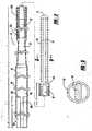
Figure 1 is a diagrammatic view showing a blood vessel that has been occluded with deposits along an inner wall and illustrating the positioning of a flexible guidewire within a blood vessel;Figure 2 is partially sectioned, elevation segmented view of a flexible guidewire constructed in accordance with the invention; andFigure 3 is an enlarged sectioned view as seen from the plane defined by the lines 3-3 inFigure 2 .- Turning now to the drawings,
Figure 1 illustrates a distal portion of a flexible,small diameter guidewire 10 that can be guided through a patient's vascular system. A distal end of the guidewire is approaching a region in ablood vessel 12 having anocclusion 14 which has restricted blood flow through theblood vessel 12. Theguidewire 10 is long enough to be routed from an entry point of the patient through the vessels of the patient to the obstructed blood vessel region. As theguidewire 10 is inserted along the tortuous path to the obstructed blood vessel region, an attending physician conducting the procedure monitors progress of theguidewire 10 on a fluorographic viewing screen. - The
Figure 1 depiction illustrates use of a guidewire for routing aballoon catheter 20 to the vicinity of theocclusion 14. Theballoon catheter 20 includes a first passageway or lumen which extends from a proximal location outside the patient's body to a distally locatedballoon 22. Adistal tip portion 24 of thecatheter 20 includes amarker band 26 to aid the attending physician in monitoring balloon catheter progress as it is positioned within the patient. A second, center passageway or lumen in thecatheter 20 has a diameter sufficient to accommodate theguidewire 10 so that once the guidewire is properly positioned thecatheter 20 can be slid over the guidewire to a desired location. - The distal tip portion of the
guidewire 10 is flexible and can be bent to a predetermined configuration to facilitate routing theguidewire 10 along the vascular system. The pre-bent tip can be oriented by the physician. Torque applied to the proximal end of the guidewire is transmitted along the length of the guidewire to orient or rotate the distal tip of the guidewire in order to direct the distal tip in a desired direction. - In use, a distal end of the
guidewire 10 is routed through a narrow passageway in theocclusion 14 and theballoon catheter 20 slipped over the guidewire until theballoon 22 bridges theocclusion 14 within theblood vessel 12. Theballoon 22 is then pressurized from a pressure source and as the balloon outer surface contacts theocclusion 14, inner walls of the obstruction are compressed and a wider lumen or passageway is created in theblood vessel 12. - Although the
Figure 1 depiction has been used to illustrate one use of the guidewire, it should be appreciated that a guidewire constructed in accordance with the invention has utility with angiographic catheters or any application requiring the routing of a tubular device within a patient, or alternatively, may be used with certain therapeutic procedures, such as the removal of an obstruction within a vessel. - Turning now to
Figure 2 , theguidewire 10 includes acorewire 40 formed from a superelastic material, such as Nitinol, having a first uniform diameter proximal portion 42 extending well over half the length of the guidewire. To increase the "torqueability," or torque characteristics of theguidewire 10, theproximal portion 42a of the uniform diameter portion 42 is ground down to a reduced diameter and astainless steel hypotube 43a is placed over the reduced diameter portion of theproximal portion 42a and is bonded to theproximal portion 42a by use of an adhesive, such as epoxy. Theproximal portion 42a of the uniform diameter portion of thecorewire 40 extends for a length "V" which is preferably about 120 cm. - Preferably, the total length of the
guidewire 10 is approximately 150 centimeters. The outer surface of a most proximal segment 45a of the guidewire having a length indicated as "U" is not covered with a lubricious coating, but the remaining length "T" of theguidewire 10 up to adistal tip portion 44a is covered with a thin Teflon coating 44. The exposed segment 45a may be more easily grasped by the attending physician in order to rotate the proximal end of theguidewire 10. - The Teflon coating which is applied to the
guidewire 10 preferably has a thickness of approximately 0.016 mm (0.00065 inch) and is applied by a hot dipping process. Thecorewire 40 tapers along aportion 50 in a uniform manner to a second reducedconstant diameter portion 52. The reducedconstant diameter portion 52 is bounded by a coiledwire spring 60. Theproximal portion 60a of thespring 60 is comprised of coil turns having a rectangular cross-section and the distal portion 60b of thespring 60 is comprised of coil turns having a circular cross-section. - The
spring 60 separates from thecorewire 40 where the core begins to taper in a uniform manner along aportion 62. Adistal portion 64 of thecorewire 40 is flattened and surrounded by the less tightly coiled portion of thespring 60. This distal portion of theguidewire 10 may be pre-bent to a particular configuration by the attending physician to facilitate insertion of the guidewire within the vessels of a patient. - At the extreme distal tip portion of the
guidewire 10,braze material 70 is used to attach the distal portion of thespring 60 to the flattenedportion 64 of thecorewire 40. A preferred braze material is a gold alloy which upon being applied defines a hemispherical bead which covers several coils and is polished to a smooth shape so that it does not damage the inner lining of the blood vessels as the tip comes in contact with those linings. - The dimensions shown are for a preferred embodiment in the invention for use in small diameter blood vessels. These dimensions are representative of this use and are not intended to limit the invention, but rather define a small diameter guidewire whose characteristics are particularly advantageous.
Claims (8)
- An elongated flexible guidewire (10) having a proximal end, the guidewire (10) comprising:a flexible corewire (40) formed from a superelastic material and having a first constant diameter portion (42) that tapers distally along a first tapered portion (50), a proximal section (42a) of said first constant diameter portion (42) having a reduced diameter section from that of said first diameter portion;a hypotube (43a) extending over said proximal section (42a) of said first constant diameter portion (42) and being bonded to said proximal section (42a);a flexible coil (60) surrounding a portion of the corewire (40) and attached to a distal tip of said first tapered portion (50); and,a polymer coating (44) covering an outer surface of said guidewire (10) extending over a major portion of the guidewire (10);characterised in that the proximal section (42a) extends-from said proximal end of said guidewire (10),
- An elongated flexible guidewire (10) according to claim 1 wherein:the first constant diameter portion (42) of the flexible corewire (40) tapers distally along a first tapered portion (50) to a second lesser constant diameter portion (52) shorter than said first diameter portion (42) and that again tapers distally along a second tapered portion (62) to a flattened distal portion (64) of said corewire (40); and the flexible coil (60) surrounding the corewire (40) is attached to the corewire (40) along a length of the second lesser constant diameter portion (52) of the corewire (40) and attached to a distal end of the flattened distal portion (64) of the corewire (40).
- An elongated flexible guidewire (10) as defined in Claim 2, wherein the coil (60) is attached to the distal end of the flattened distal portion (64) of the corewire (40) with a brazing material (70) which forms a rounded distal tip of the guidewire.
- An elongated flexible guidewire (10) as defined in Claim 3, wherein an outer diameter of said hypotube (43a) is approximately equal to a diameter of the first constant diameter portion (42).
- An elongated flexible guidewire (10) as defined in Claim 1 or 2, wherein said hypotube (43a) is formed of stainless steel.
- An elongated flexible guidewire (10) as defined in Claim 5, wherein said hypotube (43a) is bonded to said reduced diameter section (42a) with an adhesive material.
- An elongated flexible guidewire (10) as defined in Claim 6, wherein said adhesive material is an epoxy.
- An elongated flexible guidewire (10) as defined in Claim 1 or 2, wherein said hypotube (43a) extends from the proximal section of the guidewire for at least one-half the length of the guidewire.
Applications Claiming Priority (1)
| Application Number | Priority Date | Filing Date | Title |
|---|---|---|---|
| US11/047,220US20060173382A1 (en) | 2005-01-31 | 2005-01-31 | Guidewire with superelastic core |
Publications (2)
| Publication Number | Publication Date |
|---|---|
| EP1685870A1 EP1685870A1 (en) | 2006-08-02 |
| EP1685870B1true EP1685870B1 (en) | 2008-12-10 |
Family
ID=36001102
Family Applications (1)
| Application Number | Title | Priority Date | Filing Date |
|---|---|---|---|
| EP06250408ACeasedEP1685870B1 (en) | 2005-01-31 | 2006-01-25 | Guidewire with superelastic core |
Country Status (6)
| Country | Link |
|---|---|
| US (1) | US20060173382A1 (en) |
| EP (1) | EP1685870B1 (en) |
| JP (1) | JP2006212428A (en) |
| AT (1) | ATE416814T1 (en) |
| CA (1) | CA2534610C (en) |
| DE (1) | DE602006004081D1 (en) |
Families Citing this family (50)
| Publication number | Priority date | Publication date | Assignee | Title |
|---|---|---|---|---|
| DE10105592A1 (en) | 2001-02-06 | 2002-08-08 | Achim Goepferich | Placeholder for drug release in the frontal sinus |
| US8317816B2 (en) | 2002-09-30 | 2012-11-27 | Acclarent, Inc. | Balloon catheters and methods for treating paranasal sinuses |
| US7591813B2 (en) | 2003-10-01 | 2009-09-22 | Micrus Endovascular Corporation | Long nose manipulatable catheter |
| US8414524B2 (en) | 2003-10-01 | 2013-04-09 | Micrus Endovascular Corporation | Long nose manipulatable catheter |
| US8864787B2 (en) | 2004-04-21 | 2014-10-21 | Acclarent, Inc. | Ethmoidotomy system and implantable spacer devices having therapeutic substance delivery capability for treatment of paranasal sinusitis |
| US20060063973A1 (en) | 2004-04-21 | 2006-03-23 | Acclarent, Inc. | Methods and apparatus for treating disorders of the ear, nose and throat |
| US20190314620A1 (en) | 2004-04-21 | 2019-10-17 | Acclarent, Inc. | Apparatus and methods for dilating and modifying ostia of paranasal sinuses and other intranasal or paranasal structures |
| US8932276B1 (en) | 2004-04-21 | 2015-01-13 | Acclarent, Inc. | Shapeable guide catheters and related methods |
| US9089258B2 (en) | 2004-04-21 | 2015-07-28 | Acclarent, Inc. | Endoscopic methods and devices for transnasal procedures |
| US7654997B2 (en) | 2004-04-21 | 2010-02-02 | Acclarent, Inc. | Devices, systems and methods for diagnosing and treating sinusitus and other disorders of the ears, nose and/or throat |
| US10188413B1 (en) | 2004-04-21 | 2019-01-29 | Acclarent, Inc. | Deflectable guide catheters and related methods |
| US8702626B1 (en) | 2004-04-21 | 2014-04-22 | Acclarent, Inc. | Guidewires for performing image guided procedures |
| US7361168B2 (en) | 2004-04-21 | 2008-04-22 | Acclarent, Inc. | Implantable device and methods for delivering drugs and other substances to treat sinusitis and other disorders |
| US9554691B2 (en) | 2004-04-21 | 2017-01-31 | Acclarent, Inc. | Endoscopic methods and devices for transnasal procedures |
| US7559925B2 (en) | 2006-09-15 | 2009-07-14 | Acclarent Inc. | Methods and devices for facilitating visualization in a surgical environment |
| US8747389B2 (en) | 2004-04-21 | 2014-06-10 | Acclarent, Inc. | Systems for treating disorders of the ear, nose and throat |
| US7462175B2 (en) | 2004-04-21 | 2008-12-09 | Acclarent, Inc. | Devices, systems and methods for treating disorders of the ear, nose and throat |
| US7803150B2 (en) | 2004-04-21 | 2010-09-28 | Acclarent, Inc. | Devices, systems and methods useable for treating sinusitis |
| US8764729B2 (en) | 2004-04-21 | 2014-07-01 | Acclarent, Inc. | Frontal sinus spacer |
| US8894614B2 (en) | 2004-04-21 | 2014-11-25 | Acclarent, Inc. | Devices, systems and methods useable for treating frontal sinusitis |
| US9351750B2 (en) | 2004-04-21 | 2016-05-31 | Acclarent, Inc. | Devices and methods for treating maxillary sinus disease |
| US20070208252A1 (en) | 2004-04-21 | 2007-09-06 | Acclarent, Inc. | Systems and methods for performing image guided procedures within the ear, nose, throat and paranasal sinuses |
| US9399121B2 (en) | 2004-04-21 | 2016-07-26 | Acclarent, Inc. | Systems and methods for transnasal dilation of passageways in the ear, nose or throat |
| US20060004323A1 (en) | 2004-04-21 | 2006-01-05 | Exploramed Nc1, Inc. | Apparatus and methods for dilating and modifying ostia of paranasal sinuses and other intranasal or paranasal structures |
| US9101384B2 (en) | 2004-04-21 | 2015-08-11 | Acclarent, Inc. | Devices, systems and methods for diagnosing and treating sinusitis and other disorders of the ears, Nose and/or throat |
| US8146400B2 (en) | 2004-04-21 | 2012-04-03 | Acclarent, Inc. | Endoscopic methods and devices for transnasal procedures |
| US20070167682A1 (en) | 2004-04-21 | 2007-07-19 | Acclarent, Inc. | Endoscopic methods and devices for transnasal procedures |
| US7410480B2 (en) | 2004-04-21 | 2008-08-12 | Acclarent, Inc. | Devices and methods for delivering therapeutic substances for the treatment of sinusitis and other disorders |
| US7419497B2 (en) | 2004-04-21 | 2008-09-02 | Acclarent, Inc. | Methods for treating ethmoid disease |
| US8951225B2 (en) | 2005-06-10 | 2015-02-10 | Acclarent, Inc. | Catheters with non-removable guide members useable for treatment of sinusitis |
| US8114113B2 (en) | 2005-09-23 | 2012-02-14 | Acclarent, Inc. | Multi-conduit balloon catheter |
| US8190389B2 (en) | 2006-05-17 | 2012-05-29 | Acclarent, Inc. | Adapter for attaching electromagnetic image guidance components to a medical device |
| US9820688B2 (en) | 2006-09-15 | 2017-11-21 | Acclarent, Inc. | Sinus illumination lightwire device |
| US8439687B1 (en) | 2006-12-29 | 2013-05-14 | Acclarent, Inc. | Apparatus and method for simulated insertion and positioning of guidewares and other interventional devices |
| US8118757B2 (en) | 2007-04-30 | 2012-02-21 | Acclarent, Inc. | Methods and devices for ostium measurement |
| US8485199B2 (en) | 2007-05-08 | 2013-07-16 | Acclarent, Inc. | Methods and devices for protecting nasal turbinate during surgery |
| US10206821B2 (en) | 2007-12-20 | 2019-02-19 | Acclarent, Inc. | Eustachian tube dilation balloon with ventilation path |
| US8182432B2 (en) | 2008-03-10 | 2012-05-22 | Acclarent, Inc. | Corewire design and construction for medical devices |
| RU2500337C2 (en) | 2008-07-30 | 2013-12-10 | Аккларент, Инк. | Device and methods of identifying orifice of paranasal sinus |
| BRPI0919195A2 (en) | 2008-09-18 | 2019-09-24 | Acclarent Inc | Methods and Apparatus for the Treatment of Ear, Nose, and Throat Disorders |
| US20100241155A1 (en) | 2009-03-20 | 2010-09-23 | Acclarent, Inc. | Guide system with suction |
| US7978742B1 (en) | 2010-03-24 | 2011-07-12 | Corning Incorporated | Methods for operating diode lasers |
| US8435290B2 (en) | 2009-03-31 | 2013-05-07 | Acclarent, Inc. | System and method for treatment of non-ventilating middle ear by providing a gas pathway through the nasopharynx |
| US9155492B2 (en) | 2010-09-24 | 2015-10-13 | Acclarent, Inc. | Sinus illumination lightwire device |
| US9433437B2 (en) | 2013-03-15 | 2016-09-06 | Acclarent, Inc. | Apparatus and method for treatment of ethmoid sinusitis |
| US9629684B2 (en) | 2013-03-15 | 2017-04-25 | Acclarent, Inc. | Apparatus and method for treatment of ethmoid sinusitis |
| WO2015080948A1 (en)* | 2013-11-26 | 2015-06-04 | Boston Scientific Scimed, Inc. | Medical devices for accessing body lumens |
| WO2017147493A1 (en) | 2016-02-24 | 2017-08-31 | Incept, Llc | Enhanced flexibility neurovascular catheter |
| US20190060618A1 (en)* | 2017-08-25 | 2019-02-28 | Acclarent, Inc. | Core wire assembly for guidewire |
| CN114340713B (en) | 2019-09-13 | 2025-02-25 | 史赛克公司 | Image guided surgical system guidewire and method of manufacture and use |
Family Cites Families (28)
| Publication number | Priority date | Publication date | Assignee | Title |
|---|---|---|---|---|
| US3789841A (en)* | 1971-09-15 | 1974-02-05 | Becton Dickinson Co | Disposable guide wire |
| US3906938A (en)* | 1974-09-03 | 1975-09-23 | Lake Region Manufacturing Comp | Coil spring wire guide |
| US4545390A (en)* | 1982-09-22 | 1985-10-08 | C. R. Bard, Inc. | Steerable guide wire for balloon dilatation procedure |
| US4538622A (en)* | 1983-11-10 | 1985-09-03 | Advanced Cardiovascular Systems, Inc. | Guide wire for catheters |
| US4813434A (en)* | 1987-02-17 | 1989-03-21 | Medtronic Versaflex, Inc. | Steerable guidewire with deflectable tip |
| US4815478A (en)* | 1987-02-17 | 1989-03-28 | Medtronic Versaflex, Inc. | Steerable guidewire with deflectable tip |
| US4846186A (en)* | 1988-01-12 | 1989-07-11 | Cordis Corporation | Flexible guidewire |
| US4940062A (en)* | 1988-05-26 | 1990-07-10 | Advanced Cardiovascular Systems, Inc. | Guiding member with deflectable tip |
| US5203772A (en)* | 1989-01-09 | 1993-04-20 | Pilot Cardiovascular Systems, Inc. | Steerable medical device |
| US5037391A (en)* | 1989-01-09 | 1991-08-06 | Pilot Cardiovascular Systems, Inc. | Steerable angioplasty device |
| US5372587A (en)* | 1989-01-09 | 1994-12-13 | Pilot Cariovascular Systems, Inc. | Steerable medical device |
| EP0395098B1 (en)* | 1989-04-28 | 1994-04-06 | Tokin Corporation | Readily operable catheter guide wire using shape memory alloy with pseudo elasticity |
| US5147317A (en)* | 1990-06-04 | 1992-09-15 | C.R. Bard, Inc. | Low friction varied radiopacity guidewire |
| US5069217A (en)* | 1990-07-09 | 1991-12-03 | Lake Region Manufacturing Co., Inc. | Steerable guide wire |
| US5341818A (en)* | 1992-12-22 | 1994-08-30 | Advanced Cardiovascular Systems, Inc. | Guidewire with superelastic distal portion |
| US5749837A (en)* | 1993-05-11 | 1998-05-12 | Target Therapeutics, Inc. | Enhanced lubricity guidewire |
| US5402799A (en)* | 1993-06-29 | 1995-04-04 | Cordis Corporation | Guidewire having flexible floppy tip |
| US5404887A (en)* | 1993-11-04 | 1995-04-11 | Scimed Life Systems, Inc. | Guide wire having an unsmooth exterior surface |
| US5636641A (en)* | 1994-07-25 | 1997-06-10 | Advanced Cardiovascular Systems, Inc. | High strength member for intracorporeal use |
| US6488637B1 (en)* | 1996-04-30 | 2002-12-03 | Target Therapeutics, Inc. | Composite endovascular guidewire |
| US5876356A (en)* | 1997-04-02 | 1999-03-02 | Cordis Corporation | Superelastic guidewire with a shapeable tip |
| US6059739A (en)* | 1998-05-29 | 2000-05-09 | Medtronic, Inc. | Method and apparatus for deflecting a catheter or lead |
| US6165140A (en)* | 1998-12-28 | 2000-12-26 | Micrus Corporation | Composite guidewire |
| US6464650B2 (en)* | 1998-12-31 | 2002-10-15 | Advanced Cardiovascular Systems, Inc. | Guidewire with smoothly tapered segment |
| US6146338A (en)* | 1999-04-23 | 2000-11-14 | Medtronic, Inc. | Apparatus for deflecting a catheter or lead |
| US6126649A (en)* | 1999-06-10 | 2000-10-03 | Transvascular, Inc. | Steerable catheter with external guidewire as catheter tip deflector |
| US6638267B1 (en)* | 2000-12-01 | 2003-10-28 | Advanced Cardiovascular Systems, Inc. | Guidewire with hypotube and internal insert |
| US7182735B2 (en)* | 2003-02-26 | 2007-02-27 | Scimed Life Systems, Inc. | Elongated intracorporal medical device |
- 2005
- 2005-01-31USUS11/047,220patent/US20060173382A1/ennot_activeAbandoned
- 2006
- 2006-01-25ATAT06250408Tpatent/ATE416814T1/ennot_activeIP Right Cessation
- 2006-01-25EPEP06250408Apatent/EP1685870B1/ennot_activeCeased
- 2006-01-25DEDE602006004081Tpatent/DE602006004081D1/enactiveActive
- 2006-01-30JPJP2006021226Apatent/JP2006212428A/ennot_activeWithdrawn
- 2006-01-30CACA2534610Apatent/CA2534610C/enactiveActive
Also Published As
| Publication number | Publication date |
|---|---|
| CA2534610A1 (en) | 2006-07-31 |
| EP1685870A1 (en) | 2006-08-02 |
| JP2006212428A (en) | 2006-08-17 |
| US20060173382A1 (en) | 2006-08-03 |
| CA2534610C (en) | 2014-03-25 |
| ATE416814T1 (en) | 2008-12-15 |
| DE602006004081D1 (en) | 2009-01-22 |
Similar Documents
| Publication | Publication Date | Title |
|---|---|---|
| EP1685870B1 (en) | Guidewire with superelastic core | |
| US4846186A (en) | Flexible guidewire | |
| US6139511A (en) | Guidewire with variable coil configuration | |
| EP0868924B1 (en) | Superelastic guidewire with a shapeable tip | |
| EP0812600B1 (en) | Guidewire having a distal tip with variable flexibility | |
| US6409683B1 (en) | Medical guidewire with improved coil attachment | |
| CA2195484C (en) | Stiff catheter guidewire with flexible distal portion | |
| US6132389A (en) | Proximally tapered guidewire tip coil | |
| EP0823261B1 (en) | Guidewire having a distal tip that can change its shape within a vessel | |
| US5174302A (en) | Variable radiopacity guidewire with spaced highly radiopaque regions | |
| EP0832664B1 (en) | Guidewire having radiopaque distal tip | |
| CA1309634C (en) | Guiding member with deflectable tip | |
| CA2228346C (en) | Guidewire having a distal tip that can change its shape within a vessel | |
| US5368049A (en) | Superelastic formable guidewire with malleable cladding | |
| US5406960A (en) | Guidewire with integral core and marker bands | |
| US5267574A (en) | Guidewire with spring and a heat shrinkable connection | |
| US6056702A (en) | Guidewire with outer sheath | |
| US8226577B2 (en) | Composite guidewire withdrawn and filled tube construction | |
| US20030216668A1 (en) | Metal composite guide wire | |
| JP2006519058A (en) | Guide wire with multiple diameters | |
| JPH04231071A (en) | Arrangement of guide wire to be used with catheter and catheter | |
| JP4860657B2 (en) | Guide wire with outer sheath | |
| JP2024504978A (en) | Guidewire and instructions for use |
Legal Events
| Date | Code | Title | Description |
|---|---|---|---|
| PUAI | Public reference made under article 153(3) epc to a published international application that has entered the european phase | Free format text:ORIGINAL CODE: 0009012 | |
| AK | Designated contracting states | Kind code of ref document:A1 Designated state(s):AT BE BG CH CY CZ DE DK EE ES FI FR GB GR HU IE IS IT LI LT LU LV MC NL PL PT RO SE SI SK TR | |
| AX | Request for extension of the european patent | Extension state:AL BA HR MK YU | |
| 17P | Request for examination filed | Effective date:20070123 | |
| 17Q | First examination report despatched | Effective date:20070226 | |
| AKX | Designation fees paid | Designated state(s):AT BE BG CH CY CZ DE DK EE ES FI FR GB GR HU IE IS IT LI LT LU LV MC NL PL PT RO SE SI SK TR | |
| GRAP | Despatch of communication of intention to grant a patent | Free format text:ORIGINAL CODE: EPIDOSNIGR1 | |
| GRAS | Grant fee paid | Free format text:ORIGINAL CODE: EPIDOSNIGR3 | |
| GRAA | (expected) grant | Free format text:ORIGINAL CODE: 0009210 | |
| AK | Designated contracting states | Kind code of ref document:B1 Designated state(s):AT BE BG CH CY CZ DE DK EE ES FI FR GB GR HU IE IS IT LI LT LU LV MC NL PL PT RO SE SI SK TR | |
| REG | Reference to a national code | Ref country code:GB Ref legal event code:FG4D | |
| REG | Reference to a national code | Ref country code:CH Ref legal event code:EP | |
| REG | Reference to a national code | Ref country code:IE Ref legal event code:FG4D | |
| REF | Corresponds to: | Ref document number:602006004081 Country of ref document:DE Date of ref document:20090122 Kind code of ref document:P | |
| PG25 | Lapsed in a contracting state [announced via postgrant information from national office to epo] | Ref country code:LT Free format text:LAPSE BECAUSE OF FAILURE TO SUBMIT A TRANSLATION OF THE DESCRIPTION OR TO PAY THE FEE WITHIN THE PRESCRIBED TIME-LIMIT Effective date:20081210 | |
| PG25 | Lapsed in a contracting state [announced via postgrant information from national office to epo] | Ref country code:LV Free format text:LAPSE BECAUSE OF FAILURE TO SUBMIT A TRANSLATION OF THE DESCRIPTION OR TO PAY THE FEE WITHIN THE PRESCRIBED TIME-LIMIT Effective date:20081210 Ref country code:SI Free format text:LAPSE BECAUSE OF FAILURE TO SUBMIT A TRANSLATION OF THE DESCRIPTION OR TO PAY THE FEE WITHIN THE PRESCRIBED TIME-LIMIT Effective date:20081210 Ref country code:PL Free format text:LAPSE BECAUSE OF FAILURE TO SUBMIT A TRANSLATION OF THE DESCRIPTION OR TO PAY THE FEE WITHIN THE PRESCRIBED TIME-LIMIT Effective date:20081210 Ref country code:FI Free format text:LAPSE BECAUSE OF FAILURE TO SUBMIT A TRANSLATION OF THE DESCRIPTION OR TO PAY THE FEE WITHIN THE PRESCRIBED TIME-LIMIT Effective date:20081210 | |
| PG25 | Lapsed in a contracting state [announced via postgrant information from national office to epo] | Ref country code:RO Free format text:LAPSE BECAUSE OF FAILURE TO SUBMIT A TRANSLATION OF THE DESCRIPTION OR TO PAY THE FEE WITHIN THE PRESCRIBED TIME-LIMIT Effective date:20081210 Ref country code:ES Free format text:LAPSE BECAUSE OF FAILURE TO SUBMIT A TRANSLATION OF THE DESCRIPTION OR TO PAY THE FEE WITHIN THE PRESCRIBED TIME-LIMIT Effective date:20090321 Ref country code:BE Free format text:LAPSE BECAUSE OF FAILURE TO SUBMIT A TRANSLATION OF THE DESCRIPTION OR TO PAY THE FEE WITHIN THE PRESCRIBED TIME-LIMIT Effective date:20081210 Ref country code:BG Free format text:LAPSE BECAUSE OF FAILURE TO SUBMIT A TRANSLATION OF THE DESCRIPTION OR TO PAY THE FEE WITHIN THE PRESCRIBED TIME-LIMIT Effective date:20090310 Ref country code:EE Free format text:LAPSE BECAUSE OF FAILURE TO SUBMIT A TRANSLATION OF THE DESCRIPTION OR TO PAY THE FEE WITHIN THE PRESCRIBED TIME-LIMIT Effective date:20081210 | |
| PG25 | Lapsed in a contracting state [announced via postgrant information from national office to epo] | Ref country code:MC Free format text:LAPSE BECAUSE OF NON-PAYMENT OF DUE FEES Effective date:20090131 Ref country code:SE Free format text:LAPSE BECAUSE OF FAILURE TO SUBMIT A TRANSLATION OF THE DESCRIPTION OR TO PAY THE FEE WITHIN THE PRESCRIBED TIME-LIMIT Effective date:20090310 Ref country code:PT Free format text:LAPSE BECAUSE OF FAILURE TO SUBMIT A TRANSLATION OF THE DESCRIPTION OR TO PAY THE FEE WITHIN THE PRESCRIBED TIME-LIMIT Effective date:20090511 Ref country code:AT Free format text:LAPSE BECAUSE OF FAILURE TO SUBMIT A TRANSLATION OF THE DESCRIPTION OR TO PAY THE FEE WITHIN THE PRESCRIBED TIME-LIMIT Effective date:20081210 Ref country code:IS Free format text:LAPSE BECAUSE OF FAILURE TO SUBMIT A TRANSLATION OF THE DESCRIPTION OR TO PAY THE FEE WITHIN THE PRESCRIBED TIME-LIMIT Effective date:20090410 Ref country code:CZ Free format text:LAPSE BECAUSE OF FAILURE TO SUBMIT A TRANSLATION OF THE DESCRIPTION OR TO PAY THE FEE WITHIN THE PRESCRIBED TIME-LIMIT Effective date:20081210 | |
| PG25 | Lapsed in a contracting state [announced via postgrant information from national office to epo] | Ref country code:SK Free format text:LAPSE BECAUSE OF FAILURE TO SUBMIT A TRANSLATION OF THE DESCRIPTION OR TO PAY THE FEE WITHIN THE PRESCRIBED TIME-LIMIT Effective date:20081210 | |
| PLBE | No opposition filed within time limit | Free format text:ORIGINAL CODE: 0009261 | |
| STAA | Information on the status of an ep patent application or granted ep patent | Free format text:STATUS: NO OPPOSITION FILED WITHIN TIME LIMIT | |
| PG25 | Lapsed in a contracting state [announced via postgrant information from national office to epo] | Ref country code:DK Free format text:LAPSE BECAUSE OF FAILURE TO SUBMIT A TRANSLATION OF THE DESCRIPTION OR TO PAY THE FEE WITHIN THE PRESCRIBED TIME-LIMIT Effective date:20081210 | |
| 26N | No opposition filed | Effective date:20090911 | |
| PG25 | Lapsed in a contracting state [announced via postgrant information from national office to epo] | Ref country code:IE Free format text:LAPSE BECAUSE OF NON-PAYMENT OF DUE FEES Effective date:20090125 | |
| REG | Reference to a national code | Ref country code:CH Ref legal event code:PL | |
| PG25 | Lapsed in a contracting state [announced via postgrant information from national office to epo] | Ref country code:LI Free format text:LAPSE BECAUSE OF NON-PAYMENT OF DUE FEES Effective date:20100131 Ref country code:GR Free format text:LAPSE BECAUSE OF FAILURE TO SUBMIT A TRANSLATION OF THE DESCRIPTION OR TO PAY THE FEE WITHIN THE PRESCRIBED TIME-LIMIT Effective date:20090311 Ref country code:CH Free format text:LAPSE BECAUSE OF NON-PAYMENT OF DUE FEES Effective date:20100131 | |
| PG25 | Lapsed in a contracting state [announced via postgrant information from national office to epo] | Ref country code:IT Free format text:LAPSE BECAUSE OF FAILURE TO SUBMIT A TRANSLATION OF THE DESCRIPTION OR TO PAY THE FEE WITHIN THE PRESCRIBED TIME-LIMIT Effective date:20081210 | |
| PG25 | Lapsed in a contracting state [announced via postgrant information from national office to epo] | Ref country code:LU Free format text:LAPSE BECAUSE OF NON-PAYMENT OF DUE FEES Effective date:20090125 | |
| PG25 | Lapsed in a contracting state [announced via postgrant information from national office to epo] | Ref country code:HU Free format text:LAPSE BECAUSE OF FAILURE TO SUBMIT A TRANSLATION OF THE DESCRIPTION OR TO PAY THE FEE WITHIN THE PRESCRIBED TIME-LIMIT Effective date:20090611 | |
| PG25 | Lapsed in a contracting state [announced via postgrant information from national office to epo] | Ref country code:TR Free format text:LAPSE BECAUSE OF FAILURE TO SUBMIT A TRANSLATION OF THE DESCRIPTION OR TO PAY THE FEE WITHIN THE PRESCRIBED TIME-LIMIT Effective date:20081210 | |
| PG25 | Lapsed in a contracting state [announced via postgrant information from national office to epo] | Ref country code:CY Free format text:LAPSE BECAUSE OF FAILURE TO SUBMIT A TRANSLATION OF THE DESCRIPTION OR TO PAY THE FEE WITHIN THE PRESCRIBED TIME-LIMIT Effective date:20081210 | |
| REG | Reference to a national code | Ref country code:FR Ref legal event code:PLFP Year of fee payment:11 | |
| REG | Reference to a national code | Ref country code:FR Ref legal event code:PLFP Year of fee payment:12 | |
| REG | Reference to a national code | Ref country code:FR Ref legal event code:PLFP Year of fee payment:13 | |
| REG | Reference to a national code | Ref country code:GB Ref legal event code:732E Free format text:REGISTERED BETWEEN 20180614 AND 20180620 | |
| REG | Reference to a national code | Ref country code:DE Ref legal event code:R082 Ref document number:602006004081 Country of ref document:DE Representative=s name:PROCK, THOMAS, DR., GB | |
| REG | Reference to a national code | Ref country code:NL Ref legal event code:PD Owner name:CARDINAL HEALTH SWITZERLAND 515 GMBH; CH Free format text:DETAILS ASSIGNMENT: CHANGE OF OWNER(S), ASSIGNMENT; FORMER OWNER NAME: CORDIS CORPORATION Effective date:20200708 | |
| REG | Reference to a national code | Ref country code:GB Ref legal event code:732E Free format text:REGISTERED BETWEEN 20201126 AND 20201202 | |
| REG | Reference to a national code | Ref country code:DE Ref legal event code:R082 Ref document number:602006004081 Country of ref document:DE Representative=s name:PROCK, THOMAS, DR., GB Ref country code:DE Ref legal event code:R081 Ref document number:602006004081 Country of ref document:DE Owner name:CARDINAL HEALTH SWITZERLAND 515 GMBH, CH Free format text:FORMER OWNER: CORDIS CORP., MIAMI LAKES, FLA., US | |
| PGFP | Annual fee paid to national office [announced via postgrant information from national office to epo] | Ref country code:GB Payment date:20220127 Year of fee payment:17 Ref country code:DE Payment date:20220127 Year of fee payment:17 | |
| PGFP | Annual fee paid to national office [announced via postgrant information from national office to epo] | Ref country code:NL Payment date:20220126 Year of fee payment:17 Ref country code:FR Payment date:20220125 Year of fee payment:17 | |
| REG | Reference to a national code | Ref country code:DE Ref legal event code:R119 Ref document number:602006004081 Country of ref document:DE | |
| REG | Reference to a national code | Ref country code:NL Ref legal event code:MM Effective date:20230201 | |
| GBPC | Gb: european patent ceased through non-payment of renewal fee | Effective date:20230125 | |
| PG25 | Lapsed in a contracting state [announced via postgrant information from national office to epo] | Ref country code:NL Free format text:LAPSE BECAUSE OF NON-PAYMENT OF DUE FEES Effective date:20230201 Ref country code:GB Free format text:LAPSE BECAUSE OF NON-PAYMENT OF DUE FEES Effective date:20230125 Ref country code:DE Free format text:LAPSE BECAUSE OF NON-PAYMENT OF DUE FEES Effective date:20230801 | |
| PG25 | Lapsed in a contracting state [announced via postgrant information from national office to epo] | Ref country code:FR Free format text:LAPSE BECAUSE OF NON-PAYMENT OF DUE FEES Effective date:20230131 |