EP1685366B1 - Method and apparatus for performing optical imaging using frequency-domain interferometry - Google Patents
Method and apparatus for performing optical imaging using frequency-domain interferometryDownload PDFInfo
- Publication number
- EP1685366B1 EP1685366B1EP04788614AEP04788614AEP1685366B1EP 1685366 B1EP1685366 B1EP 1685366B1EP 04788614 AEP04788614 AEP 04788614AEP 04788614 AEP04788614 AEP 04788614AEP 1685366 B1EP1685366 B1EP 1685366B1
- Authority
- EP
- European Patent Office
- Prior art keywords
- radiation
- frequency
- sample
- electro
- signal
- Prior art date
- Legal status (The legal status is an assumption and is not a legal conclusion. Google has not performed a legal analysis and makes no representation as to the accuracy of the status listed.)
- Expired - Lifetime
Links
Images


Classifications
- H—ELECTRICITY
- H01—ELECTRIC ELEMENTS
- H01S—DEVICES USING THE PROCESS OF LIGHT AMPLIFICATION BY STIMULATED EMISSION OF RADIATION [LASER] TO AMPLIFY OR GENERATE LIGHT; DEVICES USING STIMULATED EMISSION OF ELECTROMAGNETIC RADIATION IN WAVE RANGES OTHER THAN OPTICAL
- H01S5/00—Semiconductor lasers
- H01S5/50—Amplifier structures not provided for in groups H01S5/02 - H01S5/30
- H01S5/5045—Amplifier structures not provided for in groups H01S5/02 - H01S5/30 the arrangement having a frequency filtering function
- G—PHYSICS
- G01—MEASURING; TESTING
- G01J—MEASUREMENT OF INTENSITY, VELOCITY, SPECTRAL CONTENT, POLARISATION, PHASE OR PULSE CHARACTERISTICS OF INFRARED, VISIBLE OR ULTRAVIOLET LIGHT; COLORIMETRY; RADIATION PYROMETRY
- G01J9/00—Measuring optical phase difference; Determining degree of coherence; Measuring optical wavelength
- G01J9/02—Measuring optical phase difference; Determining degree of coherence; Measuring optical wavelength by interferometric methods
- A—HUMAN NECESSITIES
- A61—MEDICAL OR VETERINARY SCIENCE; HYGIENE
- A61B—DIAGNOSIS; SURGERY; IDENTIFICATION
- A61B5/00—Measuring for diagnostic purposes; Identification of persons
- A—HUMAN NECESSITIES
- A61—MEDICAL OR VETERINARY SCIENCE; HYGIENE
- A61B—DIAGNOSIS; SURGERY; IDENTIFICATION
- A61B5/00—Measuring for diagnostic purposes; Identification of persons
- A61B5/0059—Measuring for diagnostic purposes; Identification of persons using light, e.g. diagnosis by transillumination, diascopy, fluorescence
- A61B5/0062—Arrangements for scanning
- A61B5/0066—Optical coherence imaging
- G—PHYSICS
- G01—MEASURING; TESTING
- G01B—MEASURING LENGTH, THICKNESS OR SIMILAR LINEAR DIMENSIONS; MEASURING ANGLES; MEASURING AREAS; MEASURING IRREGULARITIES OF SURFACES OR CONTOURS
- G01B9/00—Measuring instruments characterised by the use of optical techniques
- G01B9/02—Interferometers
- G—PHYSICS
- G01—MEASURING; TESTING
- G01B—MEASURING LENGTH, THICKNESS OR SIMILAR LINEAR DIMENSIONS; MEASURING ANGLES; MEASURING AREAS; MEASURING IRREGULARITIES OF SURFACES OR CONTOURS
- G01B9/00—Measuring instruments characterised by the use of optical techniques
- G01B9/02—Interferometers
- G01B9/02001—Interferometers characterised by controlling or generating intrinsic radiation properties
- G01B9/02002—Interferometers characterised by controlling or generating intrinsic radiation properties using two or more frequencies
- G01B9/02004—Interferometers characterised by controlling or generating intrinsic radiation properties using two or more frequencies using frequency scans
- G—PHYSICS
- G01—MEASURING; TESTING
- G01B—MEASURING LENGTH, THICKNESS OR SIMILAR LINEAR DIMENSIONS; MEASURING ANGLES; MEASURING AREAS; MEASURING IRREGULARITIES OF SURFACES OR CONTOURS
- G01B9/00—Measuring instruments characterised by the use of optical techniques
- G01B9/02—Interferometers
- G01B9/02041—Interferometers characterised by particular imaging or detection techniques
- G01B9/02043—Imaging of the Fourier or pupil or back focal plane, i.e. angle resolved imaging
- G—PHYSICS
- G01—MEASURING; TESTING
- G01B—MEASURING LENGTH, THICKNESS OR SIMILAR LINEAR DIMENSIONS; MEASURING ANGLES; MEASURING AREAS; MEASURING IRREGULARITIES OF SURFACES OR CONTOURS
- G01B9/00—Measuring instruments characterised by the use of optical techniques
- G01B9/02—Interferometers
- G01B9/02055—Reduction or prevention of errors; Testing; Calibration
- G01B9/02075—Reduction or prevention of errors; Testing; Calibration of particular errors
- G01B9/02078—Caused by ambiguity
- G01B9/02079—Quadrature detection, i.e. detecting relatively phase-shifted signals
- G01B9/02081—Quadrature detection, i.e. detecting relatively phase-shifted signals simultaneous quadrature detection, e.g. by spatial phase shifting
- G—PHYSICS
- G01—MEASURING; TESTING
- G01B—MEASURING LENGTH, THICKNESS OR SIMILAR LINEAR DIMENSIONS; MEASURING ANGLES; MEASURING AREAS; MEASURING IRREGULARITIES OF SURFACES OR CONTOURS
- G01B9/00—Measuring instruments characterised by the use of optical techniques
- G01B9/02—Interferometers
- G01B9/02083—Interferometers characterised by particular signal processing and presentation
- G01B9/02084—Processing in the Fourier or frequency domain when not imaged in the frequency domain
- G—PHYSICS
- G01—MEASURING; TESTING
- G01B—MEASURING LENGTH, THICKNESS OR SIMILAR LINEAR DIMENSIONS; MEASURING ANGLES; MEASURING AREAS; MEASURING IRREGULARITIES OF SURFACES OR CONTOURS
- G01B9/00—Measuring instruments characterised by the use of optical techniques
- G01B9/02—Interferometers
- G01B9/0209—Low-coherence interferometers
- G01B9/02091—Tomographic interferometers, e.g. based on optical coherence
- G—PHYSICS
- G01—MEASURING; TESTING
- G01J—MEASUREMENT OF INTENSITY, VELOCITY, SPECTRAL CONTENT, POLARISATION, PHASE OR PULSE CHARACTERISTICS OF INFRARED, VISIBLE OR ULTRAVIOLET LIGHT; COLORIMETRY; RADIATION PYROMETRY
- G01J3/00—Spectrometry; Spectrophotometry; Monochromators; Measuring colours
- G01J3/02—Details
- G01J3/0205—Optical elements not provided otherwise, e.g. optical manifolds, diffusers, windows
- G01J3/0208—Optical elements not provided otherwise, e.g. optical manifolds, diffusers, windows using focussing or collimating elements, e.g. lenses or mirrors; performing aberration correction
- G—PHYSICS
- G01—MEASURING; TESTING
- G01J—MEASUREMENT OF INTENSITY, VELOCITY, SPECTRAL CONTENT, POLARISATION, PHASE OR PULSE CHARACTERISTICS OF INFRARED, VISIBLE OR ULTRAVIOLET LIGHT; COLORIMETRY; RADIATION PYROMETRY
- G01J3/00—Spectrometry; Spectrophotometry; Monochromators; Measuring colours
- G01J3/02—Details
- G01J3/0205—Optical elements not provided otherwise, e.g. optical manifolds, diffusers, windows
- G01J3/021—Optical elements not provided otherwise, e.g. optical manifolds, diffusers, windows using plane or convex mirrors, parallel phase plates, or particular reflectors
- G—PHYSICS
- G01—MEASURING; TESTING
- G01J—MEASUREMENT OF INTENSITY, VELOCITY, SPECTRAL CONTENT, POLARISATION, PHASE OR PULSE CHARACTERISTICS OF INFRARED, VISIBLE OR ULTRAVIOLET LIGHT; COLORIMETRY; RADIATION PYROMETRY
- G01J3/00—Spectrometry; Spectrophotometry; Monochromators; Measuring colours
- G01J3/02—Details
- G01J3/0205—Optical elements not provided otherwise, e.g. optical manifolds, diffusers, windows
- G01J3/0218—Optical elements not provided otherwise, e.g. optical manifolds, diffusers, windows using optical fibers
- G—PHYSICS
- G01—MEASURING; TESTING
- G01J—MEASUREMENT OF INTENSITY, VELOCITY, SPECTRAL CONTENT, POLARISATION, PHASE OR PULSE CHARACTERISTICS OF INFRARED, VISIBLE OR ULTRAVIOLET LIGHT; COLORIMETRY; RADIATION PYROMETRY
- G01J3/00—Spectrometry; Spectrophotometry; Monochromators; Measuring colours
- G01J3/02—Details
- G01J3/0264—Electrical interface; User interface
- G—PHYSICS
- G01—MEASURING; TESTING
- G01J—MEASUREMENT OF INTENSITY, VELOCITY, SPECTRAL CONTENT, POLARISATION, PHASE OR PULSE CHARACTERISTICS OF INFRARED, VISIBLE OR ULTRAVIOLET LIGHT; COLORIMETRY; RADIATION PYROMETRY
- G01J3/00—Spectrometry; Spectrophotometry; Monochromators; Measuring colours
- G01J3/28—Investigating the spectrum
- G01J3/45—Interferometric spectrometry
- G01J3/453—Interferometric spectrometry by correlation of the amplitudes
- G—PHYSICS
- G01—MEASURING; TESTING
- G01J—MEASUREMENT OF INTENSITY, VELOCITY, SPECTRAL CONTENT, POLARISATION, PHASE OR PULSE CHARACTERISTICS OF INFRARED, VISIBLE OR ULTRAVIOLET LIGHT; COLORIMETRY; RADIATION PYROMETRY
- G01J9/00—Measuring optical phase difference; Determining degree of coherence; Measuring optical wavelength
- G—PHYSICS
- G01—MEASURING; TESTING
- G01N—INVESTIGATING OR ANALYSING MATERIALS BY DETERMINING THEIR CHEMICAL OR PHYSICAL PROPERTIES
- G01N21/00—Investigating or analysing materials by the use of optical means, i.e. using sub-millimetre waves, infrared, visible or ultraviolet light
- G01N21/17—Systems in which incident light is modified in accordance with the properties of the material investigated
- G01N21/47—Scattering, i.e. diffuse reflection
- G01N21/4795—Scattering, i.e. diffuse reflection spatially resolved investigating of object in scattering medium
- G—PHYSICS
- G02—OPTICS
- G02B—OPTICAL ELEMENTS, SYSTEMS OR APPARATUS
- G02B26/00—Optical devices or arrangements for the control of light using movable or deformable optical elements
- G02B26/08—Optical devices or arrangements for the control of light using movable or deformable optical elements for controlling the direction of light
- G02B26/10—Scanning systems
- G02B26/12—Scanning systems using multifaceted mirrors
- G—PHYSICS
- G02—OPTICS
- G02B—OPTICAL ELEMENTS, SYSTEMS OR APPARATUS
- G02B27/00—Optical systems or apparatus not provided for by any of the groups G02B1/00 - G02B26/00, G02B30/00
- G02B27/48—Laser speckle optics
- G—PHYSICS
- G02—OPTICS
- G02B—OPTICAL ELEMENTS, SYSTEMS OR APPARATUS
- G02B6/00—Light guides; Structural details of arrangements comprising light guides and other optical elements, e.g. couplings
- G02B6/24—Coupling light guides
- G02B6/36—Mechanical coupling means
- G02B6/3604—Rotary joints allowing relative rotational movement between opposing fibre or fibre bundle ends
- G—PHYSICS
- G02—OPTICS
- G02F—OPTICAL DEVICES OR ARRANGEMENTS FOR THE CONTROL OF LIGHT BY MODIFICATION OF THE OPTICAL PROPERTIES OF THE MEDIA OF THE ELEMENTS INVOLVED THEREIN; NON-LINEAR OPTICS; FREQUENCY-CHANGING OF LIGHT; OPTICAL LOGIC ELEMENTS; OPTICAL ANALOGUE/DIGITAL CONVERTERS
- G02F1/00—Devices or arrangements for the control of the intensity, colour, phase, polarisation or direction of light arriving from an independent light source, e.g. switching, gating or modulating; Non-linear optics
- G02F1/01—Devices or arrangements for the control of the intensity, colour, phase, polarisation or direction of light arriving from an independent light source, e.g. switching, gating or modulating; Non-linear optics for the control of the intensity, phase, polarisation or colour
- G02F1/09—Devices or arrangements for the control of the intensity, colour, phase, polarisation or direction of light arriving from an independent light source, e.g. switching, gating or modulating; Non-linear optics for the control of the intensity, phase, polarisation or colour based on magneto-optical elements, e.g. exhibiting Faraday effect
- G02F1/093—Devices or arrangements for the control of the intensity, colour, phase, polarisation or direction of light arriving from an independent light source, e.g. switching, gating or modulating; Non-linear optics for the control of the intensity, phase, polarisation or colour based on magneto-optical elements, e.g. exhibiting Faraday effect used as non-reciprocal devices, e.g. optical isolators, circulators
- G—PHYSICS
- G02—OPTICS
- G02F—OPTICAL DEVICES OR ARRANGEMENTS FOR THE CONTROL OF LIGHT BY MODIFICATION OF THE OPTICAL PROPERTIES OF THE MEDIA OF THE ELEMENTS INVOLVED THEREIN; NON-LINEAR OPTICS; FREQUENCY-CHANGING OF LIGHT; OPTICAL LOGIC ELEMENTS; OPTICAL ANALOGUE/DIGITAL CONVERTERS
- G02F1/00—Devices or arrangements for the control of the intensity, colour, phase, polarisation or direction of light arriving from an independent light source, e.g. switching, gating or modulating; Non-linear optics
- G02F1/01—Devices or arrangements for the control of the intensity, colour, phase, polarisation or direction of light arriving from an independent light source, e.g. switching, gating or modulating; Non-linear optics for the control of the intensity, phase, polarisation or colour
- G02F1/11—Devices or arrangements for the control of the intensity, colour, phase, polarisation or direction of light arriving from an independent light source, e.g. switching, gating or modulating; Non-linear optics for the control of the intensity, phase, polarisation or colour based on acousto-optical elements, e.g. using variable diffraction by sound or like mechanical waves
- H—ELECTRICITY
- H01—ELECTRIC ELEMENTS
- H01S—DEVICES USING THE PROCESS OF LIGHT AMPLIFICATION BY STIMULATED EMISSION OF RADIATION [LASER] TO AMPLIFY OR GENERATE LIGHT; DEVICES USING STIMULATED EMISSION OF ELECTROMAGNETIC RADIATION IN WAVE RANGES OTHER THAN OPTICAL
- H01S3/00—Lasers, i.e. devices using stimulated emission of electromagnetic radiation in the infrared, visible or ultraviolet wave range
- H01S3/005—Optical devices external to the laser cavity, specially adapted for lasers, e.g. for homogenisation of the beam or for manipulating laser pulses, e.g. pulse shaping
- H01S3/0071—Beam steering, e.g. whereby a mirror outside the cavity is present to change the beam direction
- H—ELECTRICITY
- H01—ELECTRIC ELEMENTS
- H01S—DEVICES USING THE PROCESS OF LIGHT AMPLIFICATION BY STIMULATED EMISSION OF RADIATION [LASER] TO AMPLIFY OR GENERATE LIGHT; DEVICES USING STIMULATED EMISSION OF ELECTROMAGNETIC RADIATION IN WAVE RANGES OTHER THAN OPTICAL
- H01S3/00—Lasers, i.e. devices using stimulated emission of electromagnetic radiation in the infrared, visible or ultraviolet wave range
- H01S3/005—Optical devices external to the laser cavity, specially adapted for lasers, e.g. for homogenisation of the beam or for manipulating laser pulses, e.g. pulse shaping
- H01S3/0078—Frequency filtering
- H—ELECTRICITY
- H01—ELECTRIC ELEMENTS
- H01S—DEVICES USING THE PROCESS OF LIGHT AMPLIFICATION BY STIMULATED EMISSION OF RADIATION [LASER] TO AMPLIFY OR GENERATE LIGHT; DEVICES USING STIMULATED EMISSION OF ELECTROMAGNETIC RADIATION IN WAVE RANGES OTHER THAN OPTICAL
- H01S5/00—Semiconductor lasers
- H01S5/005—Optical components external to the laser cavity, specially adapted therefor, e.g. for homogenisation or merging of the beams or for manipulating laser pulses, e.g. pulse shaping
- H01S5/0071—Optical components external to the laser cavity, specially adapted therefor, e.g. for homogenisation or merging of the beams or for manipulating laser pulses, e.g. pulse shaping for beam steering, e.g. using a mirror outside the cavity to change the beam direction
- H—ELECTRICITY
- H01—ELECTRIC ELEMENTS
- H01S—DEVICES USING THE PROCESS OF LIGHT AMPLIFICATION BY STIMULATED EMISSION OF RADIATION [LASER] TO AMPLIFY OR GENERATE LIGHT; DEVICES USING STIMULATED EMISSION OF ELECTROMAGNETIC RADIATION IN WAVE RANGES OTHER THAN OPTICAL
- H01S5/00—Semiconductor lasers
- H01S5/005—Optical components external to the laser cavity, specially adapted therefor, e.g. for homogenisation or merging of the beams or for manipulating laser pulses, e.g. pulse shaping
- H01S5/0078—Optical components external to the laser cavity, specially adapted therefor, e.g. for homogenisation or merging of the beams or for manipulating laser pulses, e.g. pulse shaping for frequency filtering
- H—ELECTRICITY
- H01—ELECTRIC ELEMENTS
- H01S—DEVICES USING THE PROCESS OF LIGHT AMPLIFICATION BY STIMULATED EMISSION OF RADIATION [LASER] TO AMPLIFY OR GENERATE LIGHT; DEVICES USING STIMULATED EMISSION OF ELECTROMAGNETIC RADIATION IN WAVE RANGES OTHER THAN OPTICAL
- H01S5/00—Semiconductor lasers
- H01S5/10—Construction or shape of the optical resonator, e.g. extended or external cavity, coupled cavities, bent-guide, varying width, thickness or composition of the active region
- H01S5/1025—Extended cavities
- H—ELECTRICITY
- H01—ELECTRIC ELEMENTS
- H01S—DEVICES USING THE PROCESS OF LIGHT AMPLIFICATION BY STIMULATED EMISSION OF RADIATION [LASER] TO AMPLIFY OR GENERATE LIGHT; DEVICES USING STIMULATED EMISSION OF ELECTROMAGNETIC RADIATION IN WAVE RANGES OTHER THAN OPTICAL
- H01S5/00—Semiconductor lasers
- H01S5/10—Construction or shape of the optical resonator, e.g. extended or external cavity, coupled cavities, bent-guide, varying width, thickness or composition of the active region
- H01S5/14—External cavity lasers
- A—HUMAN NECESSITIES
- A61—MEDICAL OR VETERINARY SCIENCE; HYGIENE
- A61B—DIAGNOSIS; SURGERY; IDENTIFICATION
- A61B5/00—Measuring for diagnostic purposes; Identification of persons
- A61B5/72—Signal processing specially adapted for physiological signals or for diagnostic purposes
- A61B5/7235—Details of waveform analysis
- A61B5/7253—Details of waveform analysis characterised by using transforms
- A61B5/7257—Details of waveform analysis characterised by using transforms using Fourier transforms
- G—PHYSICS
- G01—MEASURING; TESTING
- G01B—MEASURING LENGTH, THICKNESS OR SIMILAR LINEAR DIMENSIONS; MEASURING ANGLES; MEASURING AREAS; MEASURING IRREGULARITIES OF SURFACES OR CONTOURS
- G01B2290/00—Aspects of interferometers not specifically covered by any group under G01B9/02
- G01B2290/45—Multiple detectors for detecting interferometer signals
- G—PHYSICS
- G01—MEASURING; TESTING
- G01B—MEASURING LENGTH, THICKNESS OR SIMILAR LINEAR DIMENSIONS; MEASURING ANGLES; MEASURING AREAS; MEASURING IRREGULARITIES OF SURFACES OR CONTOURS
- G01B2290/00—Aspects of interferometers not specifically covered by any group under G01B9/02
- G01B2290/70—Using polarization in the interferometer
- G—PHYSICS
- G01—MEASURING; TESTING
- G01J—MEASUREMENT OF INTENSITY, VELOCITY, SPECTRAL CONTENT, POLARISATION, PHASE OR PULSE CHARACTERISTICS OF INFRARED, VISIBLE OR ULTRAVIOLET LIGHT; COLORIMETRY; RADIATION PYROMETRY
- G01J9/00—Measuring optical phase difference; Determining degree of coherence; Measuring optical wavelength
- G01J9/02—Measuring optical phase difference; Determining degree of coherence; Measuring optical wavelength by interferometric methods
- G01J9/0215—Measuring optical phase difference; Determining degree of coherence; Measuring optical wavelength by interferometric methods by shearing interferometric methods
- H—ELECTRICITY
- H01—ELECTRIC ELEMENTS
- H01S—DEVICES USING THE PROCESS OF LIGHT AMPLIFICATION BY STIMULATED EMISSION OF RADIATION [LASER] TO AMPLIFY OR GENERATE LIGHT; DEVICES USING STIMULATED EMISSION OF ELECTROMAGNETIC RADIATION IN WAVE RANGES OTHER THAN OPTICAL
- H01S3/00—Lasers, i.e. devices using stimulated emission of electromagnetic radiation in the infrared, visible or ultraviolet wave range
- H01S3/05—Construction or shape of optical resonators; Accommodation of active medium therein; Shape of active medium
- H01S3/08—Construction or shape of optical resonators or components thereof
- H01S3/08004—Construction or shape of optical resonators or components thereof incorporating a dispersive element, e.g. a prism for wavelength selection
- H01S3/08009—Construction or shape of optical resonators or components thereof incorporating a dispersive element, e.g. a prism for wavelength selection using a diffraction grating
- H—ELECTRICITY
- H01—ELECTRIC ELEMENTS
- H01S—DEVICES USING THE PROCESS OF LIGHT AMPLIFICATION BY STIMULATED EMISSION OF RADIATION [LASER] TO AMPLIFY OR GENERATE LIGHT; DEVICES USING STIMULATED EMISSION OF ELECTROMAGNETIC RADIATION IN WAVE RANGES OTHER THAN OPTICAL
- H01S3/00—Lasers, i.e. devices using stimulated emission of electromagnetic radiation in the infrared, visible or ultraviolet wave range
- H01S3/05—Construction or shape of optical resonators; Accommodation of active medium therein; Shape of active medium
- H01S3/08—Construction or shape of optical resonators or components thereof
- H01S3/08059—Constructional details of the reflector, e.g. shape
- H01S3/08063—Graded reflectivity, e.g. variable reflectivity mirror
- H—ELECTRICITY
- H01—ELECTRIC ELEMENTS
- H01S—DEVICES USING THE PROCESS OF LIGHT AMPLIFICATION BY STIMULATED EMISSION OF RADIATION [LASER] TO AMPLIFY OR GENERATE LIGHT; DEVICES USING STIMULATED EMISSION OF ELECTROMAGNETIC RADIATION IN WAVE RANGES OTHER THAN OPTICAL
- H01S3/00—Lasers, i.e. devices using stimulated emission of electromagnetic radiation in the infrared, visible or ultraviolet wave range
- H01S3/10—Controlling the intensity, frequency, phase, polarisation or direction of the emitted radiation, e.g. switching, gating, modulating or demodulating
- H01S3/105—Controlling the intensity, frequency, phase, polarisation or direction of the emitted radiation, e.g. switching, gating, modulating or demodulating by controlling the mutual position or the reflecting properties of the reflectors of the cavity, e.g. by controlling the cavity length
- H—ELECTRICITY
- H01—ELECTRIC ELEMENTS
- H01S—DEVICES USING THE PROCESS OF LIGHT AMPLIFICATION BY STIMULATED EMISSION OF RADIATION [LASER] TO AMPLIFY OR GENERATE LIGHT; DEVICES USING STIMULATED EMISSION OF ELECTROMAGNETIC RADIATION IN WAVE RANGES OTHER THAN OPTICAL
- H01S3/00—Lasers, i.e. devices using stimulated emission of electromagnetic radiation in the infrared, visible or ultraviolet wave range
- H01S3/10—Controlling the intensity, frequency, phase, polarisation or direction of the emitted radiation, e.g. switching, gating, modulating or demodulating
- H01S3/106—Controlling the intensity, frequency, phase, polarisation or direction of the emitted radiation, e.g. switching, gating, modulating or demodulating by controlling devices placed within the cavity
- H01S3/1068—Controlling the intensity, frequency, phase, polarisation or direction of the emitted radiation, e.g. switching, gating, modulating or demodulating by controlling devices placed within the cavity using an acousto-optical device
- H—ELECTRICITY
- H01—ELECTRIC ELEMENTS
- H01S—DEVICES USING THE PROCESS OF LIGHT AMPLIFICATION BY STIMULATED EMISSION OF RADIATION [LASER] TO AMPLIFY OR GENERATE LIGHT; DEVICES USING STIMULATED EMISSION OF ELECTROMAGNETIC RADIATION IN WAVE RANGES OTHER THAN OPTICAL
- H01S5/00—Semiconductor lasers
- H01S5/10—Construction or shape of the optical resonator, e.g. extended or external cavity, coupled cavities, bent-guide, varying width, thickness or composition of the active region
- H01S5/14—External cavity lasers
- H01S5/141—External cavity lasers using a wavelength selective device, e.g. a grating or etalon
- H—ELECTRICITY
- H01—ELECTRIC ELEMENTS
- H01S—DEVICES USING THE PROCESS OF LIGHT AMPLIFICATION BY STIMULATED EMISSION OF RADIATION [LASER] TO AMPLIFY OR GENERATE LIGHT; DEVICES USING STIMULATED EMISSION OF ELECTROMAGNETIC RADIATION IN WAVE RANGES OTHER THAN OPTICAL
- H01S5/00—Semiconductor lasers
- H01S5/10—Construction or shape of the optical resonator, e.g. extended or external cavity, coupled cavities, bent-guide, varying width, thickness or composition of the active region
- H01S5/14—External cavity lasers
- H01S5/146—External cavity lasers using a fiber as external cavity
Definitions
- the present inventionrelates generally optical imaging, and more particularly to method and apparatus for performing optical imaging using frequency-domain interferometry.
- optical interferometric reflectometryis a powerful tool for performing non-invasive, high-resolution ( ⁇ 10 ⁇ m), cross-sectional imaging of a biological or other sample, to visualize micro-structural optical properties such as reflection, absorption, scattering, attenuation, birefringence, and spectroscopic analysis.
- interferometric imaging techniquesThere are a number of interferometric imaging techniques that are known in the art. These techniques in general can be divided into two major categories: (i) time-domain technique, and (ii) frequency-domain technique.
- LCILow coherence interferometry
- This techniqueuses a scanning system to vary the reference arm length and acquire the interference signal at a detector. Then, the fringe pattern is demodulated to obtain the coherence envelope of the source cross correlation function.
- Optical coherence tomographyis a technique for obtaining two- or three-dimensional images using LCI. OCT is described in U.S. Pat. No. 5,321,501 issued to Swanson et al. Multiple variants of the OCT techniques have been described, but many suffer from less than optimal signal to noise ratio (“SNR”), resulting in non-optimal resolution, low imaging frame rates, and poor depth of penetration. Power usage is a factor in such imaging techniques.
- SNRsignal to noise ratio
- Insufficient SNRcan also prevent the OCT technique from being used at a high frame rate which is important to avoid motion artifacts and overcome the short measurement time window available, for example, for in-vivo vascular imaging. Therefore, a way to improve SNR and imaging speed (e.g., the frame rate) is desired.
- Spectral interferometryis one of the frequency-domain imaging techniques.
- spectral radarthe real part of the cross spectral density of sample and reference arm light is measured with a spectrometer. Depth profile information can be encoded on the cross-spectral density modulation.
- spectral radar conceptsto increase SNR of LGI and OCT has been described previously.
- This techniqueuses a charge coupled device ("CCD") with a large number of pixels (an order of 1,000) to reach scan ranges on the order of a millimeter.
- CCDcharge coupled device
- the fast readout of the CCD devicemakes high-speed imaging possible.
- CCD devicesare relatively expensive compared to a single-element photo-receiver.
- the previously described methoduses a single CCD to acquire the data. Since the charge storage capacity is limited, it requires a reduction of the reference arm power to approximately the same level as the sample arm power, giving rise to auto correlation noise on the sample arm light. In addition, since no carrier is generated, the 1/f noise will dominate the noise in this system.
- phase instabilities in the interferometerreduce fringe visibility of the cross spectral density modulation. This shortcoming makes the technique vulnerable to motion artifacts.
- C-FMCWCoherent frequency-modulated continuous-wave reflectometry
- U.S. Patent Nos. 5,956,355 and 6,160,826 issued to Swanson et al.describes an optical imaging method and apparatus using this technique.
- the previously described imaging methodis based on using a continuously-tuned single-frequency laser as an optical source.
- the tuning wavelength rangeis required to be several tens of nanometers to achieve ranging resolution of less than 100 microns.
- the instantaneous linewidth of the lasermust be less than approximately 0.1 nm to achieve a detection range on the order of 1.0 mm.
- the tuning rateshould be greater than 10 kHz for high speed (e.g., video-rate) imaging.
- an external-cavity semiconductor lasercan be configured to achieve mode-hop-free single-frequency tuning over several tens of nanometer, the tuning rate has been less than 1 Hz due to stringent requirement on mechanical stability. A way to overcome this speed difficulty is preferable.
- WO 98/ 52021US 2003/0137669 A1 and WO 98/38907 relate to optical imaging.
- An exemplary optical frequency domain imaging (“OFDI”) systemcan include a multiple-frequency-mode (or multiple longitudinal or axial-mode) wavelength-swept laser source optically coupled to an interferometer containing a sample under study.
- the systemcan further include an arrangement which is configured to produce interferometric signals in quadrature between light reflected from a sample and a reference light and a detector disposed to receive the interferometric signals.
- an OFDI systemwhich can operate with source powers that are relatively low compared with source powers of conventional systems and/or which operate at acquisition rates which are relatively high compared with acquisition rates of conventional systems may be provided.
- the use of a swept sourceresults in an imaging system having reduced shot noise and other forms of noise which allows for much lower source powers, or much higher acquisition rates than conventional systems. This can lead to an increased detection sensitivity which results in the ability to provide real time imaging.
- imaging speedcan assist practitioners in gastrointestinal, ophthalmic and arterial imaging fields, where motion artifacts are a continuing problem. By increasing a frame rate while maintaining or improving the signal to noise ratio such artifacts can be minimized or in some cases eliminated.
- Exemplary embodimentsmay also enable the screening of large areas of tissues with OFDI and allows enables the use of clinically viable screening protocols.
- the wavelength-swept lasercan be provided that may use an optical band-pass scanning filter in the laser cavity to produce a rapidly-swept multiple-frequency-mode output.
- an optical band-pass scanning filter in the laser cavityit is not necessary to tune the laser cavity length to provide synchronous tuning of the laser spectrum. In other words, it does not require tuning the longitudinal cavity mode of the laser at the same rate as the center wavelength of the laser.
- the detectorcan be a dual-balanced receiver disposed to accept interferometric signals and to suppress the relative intensity noise in the interferometric signals.
- the gain in signal-to-noise ratio ("SNR") according 10 an exemplary embodimentis advantageous over time-domain approaches such as OCT via a performance of the signal processing in the Fourier-domain.
- the SNR enhancementis by a factor of N, the ratio of the depth range to the spatial resolution.
- the enhancement factor Ncan reach a few hundreds to several thousand. This increase in SNR enables the imaging by a factor of N times faster, or alternatively allows imaging at the same speed with a source that has N times lower power.
- the exemplary embodimentovercomes two important shortcomings of conventional LCI and OCT, e.g., source availability and scan speed.
- the factor Nmay reach more than 1,000, and allows construction of OFDI systems that can be more than three orders of magnitude improved from OCT and LCI technology currently in practice.
- the gain in SNRis achieved because, e.g., the shot noise has a white noise spectrum.
- the signal intensity present at the detector at frequency ⁇contributes only to the signal at frequency ⁇ , but the shot noise is generated at all frequencies.
- the shot noise contribution at each frequencycan be reduced, while the signal component remains the same.
- Exemplary embodimentsimprove current data acquisition speeds and availability of sources compared with OCT.
- Shot noiseis due to the statistical fluctuations of the current that are due to the quantized or discrete electric charges. The reduction of shot noise allows for much lower source powers or much higher acquisition rates. Limitations in current data acquisition rates ( ⁇ 4 frames/sec) are imposed by available source power and availability of fast mechanisms for scanning delay. An increase in the sensitivity of the detection by a factor of 8 would allow real time imaging at a speed of about 30 frames per second. An increase of the sensitivity by a factor of about 1,000-2,000 allows for the use of sources with much lower powers and higher spectral bandwidths which are readily available, cheaper to produce, and can generate higher resolution OFDI images.
- efficient detectionpreferably allows for a significant increase of acquisition speed.
- One limitation in ophthalmic applicationsis the power that is allowed to enter the eye according to the ANSI standards (approximately 700 microwatts at 830 nm).
- Current data acquisition speed in ophthalmic applicationsis approximately 100-500 A-lines per second.
- the power efficient detection techniquewould allow for A-line acquisition rates on the order of about 100,000 A-lines per second, or video rate imaging at about 3,000 A-lines per image.
- an apparatus and method according to claim 1 and claim 17is presented.
- at least one first electro-magnetic radiationis provided to a sample and at least one second electro-magnetic radiation is provided to a reference.
- a frequency of the first and/or second radiationsvaries over time.
- An interferenceis detected between at least one third radiation associated with the first radiation and at least one fourth radiation associated with the second radiation.
- the first electro-magnetic radiation and/or second electro-magnetic radiationhave a spectrum which changes over time. The spectrum may contain multiple frequencies at a particular time.
- the first and/or second electro-magnetic radiationshave a spectrum whose mean frequency changes substantially continuously over time at a tuning speed that is greater than 100 Tera Hertz per millisecond.
- the third radiationis a radiation coming from the sample
- the at least one fourth radiationis a radiation coming from the reference.
- the frequency of the first, second, third and/or fourth radiationmay be shifted.
- An imagecan be generated based on the detected interference.
- a probemay be used which scans a transverse location of the sample to generate scanning data, and provides the scanning data to the third arrangement so as to generate the image.
- the scanning datamay include the detected interference obtained at multiple transverse locations on the sample.
- At least one photodetector and at least one electrical filtermay be used which follow a photodetector, which is followed by an electrical filter.
- the electric filtermay be a bandpass filter having a center frequency that is approximately the same as a magnitude of the frequency shift by the frequency shifting arrangement.
- a transmission profile of the electrical filtercan vary substantially over its passband.
- the probemay include a rotary junction and a fiber-optic catheter. The catheter can be rotated at a speed higher than 30 revolutions per second. At least one
- At least one polarization diverse receive and/or a polarization diverse and dual balanced receivermay be used. It is further possible to track the phase difference between:
- first and second electro-magnetic radiationsare emitted, at least one of which has a spectrum whose mean frequency changes substantially continuously over time at a tuning speed that is greater than 100 Tera Hertz per millisecond.
- An apparatusmay include at least one first arrangement providing at least one first electro-magnetic radiation to a sample and at least one second electro-magnetic radiation to a reference.
- the apparatusmay also include at least one second arrangement adapted for shifting the frequency of the first electro-magnetic radiation and the second electromagnetic radiation, and an interferometer interfering the first and second electro-magnetic radiations to produce an interference signal.
- the apparatusmay include at least one second arrangement detecting the interference between the first and second electro-magnetic radiations.
- a system, method, software arrangement and storage mediumcan be provided for determining particular data associated with at least one of a structure and composition of a tissue.
- information associated with an interferometric signalis received which is formed from at least one first electro-magnetic radiation obtained from a sample and at least one second electro-magnetic radiation obtained from a reference.
- the first and/or second electro-magnetic radiationsis/are frequency-shifted.
- the informationis sampled to generate sampled data in a first format. Further, the sampled data is transformed into the particular data that is in a second format, the first and second format being different from one another.
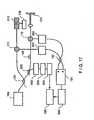
- FIG. 1shows an exemplary prior art time domain optical coherence tomography (“OCT") system 10 which includes a broadband source 12 that provides a signal to a first arm 14a of two-by-two splitter 14.
- the splitterdivides the signal provided thereto at port 14a, and provides a first portion of the signal at a port 14b coupled to a reference arm 16.
- the splitter 14also provides a second portion of the signal at a port 14c coupled to a sample arm 18.
- the sample arm 18terminates at a sample volume 19 and an arrangement 22 for providing a lateral scan of the sample volume is disposed in the sample arm 18 prior to the sample volume 19.
- the reference arm 16terminates in an arrangement 20 for providing an axial scan.
- the arrangements 20 and 22operate as is generally known in the art.
- interference fringesare formed corresponding to positions that match the distance to the three structures 19a, 19b, 19c in the sample volume 19.
- the single detector 24is used to detect the interference fringes.
- an image 26is constructed that maps tissue reflectivity to a given location.
- an exemplary embodiment of the present inventionrelates to a system which utilizes a detection principle based upon Spectral Radar concepts (further referred to as Spectral Domain OCT) and/or a hybrid method between Spectral Domain and Time Domain OCT that is preferably more sensitive than current state of the art Time Domain OCT, allowing a substantial increase in the acquisition speed to resolution ratio.
- Spectral Domain OCTSpectral Domain OCT
- thermal noiseis generated by the feedback resistor
- shot noiseis related to the finite nature of the charge quantum resulting in statistical fluctuations on the current
- relative intensity noiseis related to the temporal fluctuations due to chaotic character of classical light sources.
- N noise f4 ⁇ kT R fb + 2 ⁇ ⁇ e 2 ⁇ P ref E v + 2 ⁇ ⁇ eP ref E v 2 ⁇ ⁇ coh
- kis Boltzmann's constant
- Tthe temperature in Kelvin
- R fbthe value of the feedback resistor
- ⁇ cohthe coherence time of the source.
- SNRS N noise f ⁇ BW , with BW the signal bandwidth, and parameters S and N noise ( f ) as described above.
- the best signal to noise performance of Time Domain OCT systemsis obtained when the noise is shot noise limited. Shot noise can be reduced significantly by replacing the single element detector with a multi-element array detector. When the detection arm light is spectrally dispersed on the array detector, each element of the array detects a small wavelength fraction of the spectral width of the source. The shot noise is preferably reduced by a factor equal to the number of elements of the array.
- the principle of the signal to noise improvementis based on the white noise characteristic of shot noise and the observation that only electromagnetic waves of the same wavelength produce interference fringes.
- the shot noise power density N noise ( f )(in units [ W / Hz], [ A 2 / Hz ] or [ V 2 / Hz ]) is proportional to the current (or equivalently the optical power times the quantum efficiency) generated in the detector.
- the shot noiseis proportional to the power (or spectral density S( ⁇ ) ) at wavelength ⁇ I .
- a second wavelength ⁇ 2is preferably coupled into the interferometer.
- the shot noise at this second frequencyis preferably the sum of the shot noise generated by the optical power at wavelength ⁇ 1 and ⁇ 2 .
- the shot noiseis the sum of the shot noise generated by the optical power at wavelength ⁇ 1 and ⁇ 2 .
- a cross-shot noise termis generated by the simultaneous presence of both wavelengths at the detector.
- the cross shot noise termcan be eliminated. In this way, Spectral Domain OCT offers a significant improvement of signal to noise ratio over Time Domain OCT systems.
- the interference term of the OCT signalis proportional to the real part of the Fourier transform of the source spectrum S( ⁇ ), I ⁇ ⁇ z ⁇ oc Re ⁇ exp ik ⁇ ⁇ ⁇ z ⁇ S k ⁇ dk , with ⁇ z the path length difference between sample and reference arm and k the wave vector.
- the OCT signalis given by, I t ⁇ oc Re ⁇ exp 2 ⁇ i ⁇ rv / c ⁇ S ⁇ ⁇ d ⁇ , with v the reference arm mirror velocity.
- the frequency spectrum of the signalis given by a Fourier transform of the signal in the time domain, resulting in a complex function.
- Eq. (9)also preferably directly relates the absolute value of the frequency spectrum,
- each angular frequency of the light source or equivalently each wavelength of the sourceis represented at its own frequency in the measured interferometric signal.
- the depth profile information I(t)can be obtained from the complex cross spectral density,
- the complex cross spectral densitycan also be obtained by splitting the signal I(t) in several spectral bands using a dispersive or interferometric element. At each detector, only part of the complex cross spectral density is determined. Combining the cross spectral densities of each detector, the full spectral density of the signal are retrieved. Thus, the same information can be obtained by separating spectral components to individual detectors. Combining the signal of all detectors in software or hardware would result in the same signal as obtained with a single detector.
- the spectrumcan be split into two equal halves, where two detectors each detect one half of the spectrum.
- S( ⁇ fc / v ) for f ⁇ f 0
- I 1 ( f )0 for f > f 0
- I 2 (f)0 for f ⁇ f 0
- S( ⁇ fc / v ) for f > f 0 , respectively.
- N noise SD ⁇ oc P ref 1 ⁇ x 0.5 ⁇ BW + P ref 2 ⁇ x 0.5 ⁇ BW0.5 ⁇ P ref ⁇ BW , which may compared with the shot noise of a single detector in time domain OCT, N noise TD ⁇ oc P ref ⁇ BW .
- the signalremains the same, while the noise is reduced by a factor of 2, resulting in a net SNR gain by a factor of 2.
- N noise2 ⁇ ⁇ e 2 ⁇ P ref E v ⁇ BW N .
- Spectral Domain OCTenables a SNR improvement over Time Domain OCT of a hundred to a thousand fold, depending on the number of detector elements N.
- a charge coupled array or an integrating deviceas a detector, such as, but not limited to, a line scan camera
- FIG. 2shows an exemplary Spectral Domain OCT system 100 which includes an interferometer 102 with a source arm 104, a sample arm 106, a reference arm 108, and a detection arm 110 with a spectral separating unit 112, a detector array 114 comprised of a plurality of detectors and a like plurality of amplifiers 116.
- the amplifiers 116are coupled through optional analog processing electronics (not shown, but known to those having ordinary skill in the art), and A/D converters (not shown, but known to those skilled in the art) for conversion of signals and through digital band pass filtering ("BPF") units 122 to a processing and display unit 124.
- BPFdigital band pass filtering
- the processing and display unit 124executes data processing and display techniques, and can optionally include the digital band pass filtering ("BPF") units 122 as well as Digital Fast Fourier Transforms (“'DFFTs”) circuits (not shown), in order to provide coherent combination of signals and to perform the data processing and display functions.
- the detector array 114may be 1 x N for simple intensity ranging and imaging and/or Doppler sensitive detection, 2 x N for dual balanced detection, 2 x N for simple intensity ranging and/or polarization and/or Doppler sensitive detection, or 4 x N for combined dual balanced and polarization and/or Doppler sensitive detection.
- an M x N arraymay be used for arbitrary number "M" of detectors 114 to allow detection of transverse spatial information on the sample 130.
- Electro-magnetic radiation(e.g., light) is transmitted from the source along the source ann 104 to the splitting unit via and is split between the reference arm 108 and the sample arm 106.
- the lightpropagates along the sample arm to the tissue sample 130 and through the reference arm 108 to a wavelength dependent phase arrangement.
- the lightis reflected from the sample and the wavelength dependent phase arrangement back toward the splitting unit where at least portions of the reflected light are directed toward the spectral separating unit 112 (which may be provided as a grating for example).
- the detection arm lightis dispersed by the spectral separating unit 112 and the spectrum is imaged onto the detector array 114.
- the cross spectral density of reference arm 108 and sample arm 106 lightcan be determined.
- the processing and display unitreceived the signals fed thereto and performs a Fourier transform of the cross spectral density to generate depth profile information.
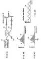
- FIG. 3Ashows a block diagram of an exemplary system which illustrates basic principles of a coherent frequency modulated continuous Wave (“C-FMCW”) system using a single-frequency tuning source.
- a monochromatic laser light 70 operable as a frequency chirped laserprovides a light signal to an input 72a of a coupler 72.
- the coupler 72divides the light signal into a reference arm 80 which terminates in a reference mirror 82 and a sample arm 84 which terminates in a sample 86.
- the lightpropagates down paths 80, 84 and reflects from the reference mirror 82 and sample mirror 86 to provide, via coupler 72, interference signals which are detected by a photo-detector 88.
- a beat signal 94(see FIG. 3D ) having a frequency f may be detected at the photo detector 88.
- the interferenceconsists of beat notes having frequencies which are proportional to the optical delay difference between the reflection (scatter) point in the sample and the reference mirror.
- the power of each beat frequency componentis proportional to the reflectivity of the scatter. Therefore, the image of the sample can be constructed by Fourier transform of the interference data.
- an optical frequency domain imaging (“OFDI”) systemincludes a wavelength-swept laser source 95 (also referred to herein as a frequency swept source 95) which provides a laser output spectrum comprised of multiple longitudinal modes to an input of a coupler 72.
- the coupler 72divides the signal fed thereto into the reference arm 80 which terminates in the reference mirror 82 and the sample arm 84 which terminates in the sample 86.
- the optical signalsreflect from the reference mirror 82 and the sample 86 to provide, via coupler 72, a spectrum of signals which are detected by a photo-detector 88.
- the center (or mean) wavelength of the signal spectrumis tuned in time by the creation of new longitudinal modes at the leading side of the spectrum and the annihilation of the modes at the trailing side of the spectrum.
- a beat signal 94can be produced.
- the beat signal 94can be generated having a beat frequency f which corresponds to the difference in the center frequency of the lights, 96 and 98, from the reference and sample, respectively.
- the frequency spacing between longitudinal modesshould be substantially larger than the detection bandwidth.
- the mode beat frequency(relative intensity noise peaks) can be removed by a proper electronic filter, such as low pass filter, prior to digitization.
- the interference signal 94contains a frequency component that is proportional to the optical delay.
- the image of the samplecan be constructed by Fourier transform of the digitized interference data.
- the wavelength-swept laser 95can be provided which utilizes an optical band-pass scanning filter in the laser cavity to produce a rapidly-swept multiple-frequency-mode output.
- Exemplary filters according to the present inventionis described below in conjunction with FIGS. 6 and 9A .
- a single pixel of the imagecan be constructed from the signal that is recorded as a function of time over the duration of one A-scan through Fourier transform. This is different from the TD OCT where a single pixel is constructed from the data measured at a short period time within one A-scan.
- the detection bandwidth to acquire the same number of data within the same A-scan periodis approximately the same for both TD and FD OCT.
- the Fourier transform used for the OFDI techniqueeffectively improves the signal-to-noise ratio compared to TD OCT by constructing a single image pixel from many data points acquired over the whole A-scan period. This effect can result in an ⁇ effective" detection bandwidth that is N-times larger than the actual detection bandwidth.
- the relative intensity noisecan be significantly higher than that of a CW broadband light source.
- a laser lightresults from different statistics and therefore has a different value than the thermal light.
- a wavelength-swept laser with a low RIN levelis preferred.
- the laser light with multiple longitudinal modesmay have a similar RIN level as the thermal light with the same linewidth. In this case, a means to suppress the RIN is critical to have sufficient SNR, such as the dual balanced detection.
- a swept sourceresults in a system having reduced shot noise and other forms of noise which allows for much lower source powers, or much higher acquisition rates than current systems.
- the increased detection sensitivityallows for real time imaging.
- imaging speedcan assist with a problem of motion artifacts, such as in gastrointestinal, ophthalmic and arterial imaging environments.
- By increasing the frame rate while maintaining or improving the signal to noise ratiosuch artifacts can be minimized.
- the present inventionalso enables one to screen large areas of tissues with the OFDI technique, and allows clinical viable screening protocols using this method.
- the efficient detectionpreferably allows for a significant increase of acquisition speed.
- a possible limitation in ophthalmic applicationsis the power that is allowed to enter the eye according to the ANSI standards (approximately 700 microwatts at 830 nm).
- Current data acquisition speed in ophthalmic applicationsis approximately 100-500 A-lines per second.
- the power efficient detectionwould allow for A-line acquisition rates on the order of about 100,000 A-lines per second, or video rate imaging at about 3,000 A-lines per image.
- the gain in SNRis achieved because the shot noise has a white noise spectrum.
- the signal intensity present at the detector at frequency ⁇(or wavelength ⁇ ) contributes only to the signal at frequency ⁇ , but the shot noise is generated at all frequencies.
- the shot noise contribution at each frequencycan be reduced, while the signal component remains the same.
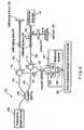
- FIG. 5shows an exemplary embodiment of a system 99 for performing optical imaging using frequency-domain interferometry ("OFDI") which includes a frequency swept source 100 that emits a narrowband spectrum of which the center wavelength is tuned continuously and repeatedly in time across the bandwidth of the gain medium in the source.
- the instantaneous emission spectrumconsists of a plurality of frequency modes of the light source.
- the frequency swept source 100may be provided in a variety of different ways, some of which are described below.
- the source 100may, for example, be provided from various gain media, tunable wavelength filters, cavity configurations.
- Devices and methodsare known in the art to provide a rapidly-tuned wavelength-swept laser source, such as solid-state lasers, active-ion-doped waveguide lasers, and fiber lasers.
- a wavelength-swept laser in a mode-locked regimecan also be used with potential advantage of a lower relative intensity noise (RIN) in a frequency region between harmonics of longitudinal-mode beat frequencies.
- RINrelative intensity noise
- An optical saturable absorbermay be incorporated inside a laser cavity or after the output port of the source to lower RIN level.
- the light provided from swept source 100is directed toward a fiber-optic coupler 102 which divides the light fed thereto into a reference arm 103 and a sample arm 104.
- the coupler 102has a 90:10 power splitting ratio with 90% of the power being directed toward the sample arm.
- the particular coupling ratio to use in any particular applicationshould be selected such that an amount of power is provided to both the reference arm and the sample arm to allow for proper operation of the exemplary system according to the present invention.
- the power provided to the sample armpasses though a circulator 111, and illuminates a sample 136 to be imaged through a transverse-scanning imaging probe.
- the reference armprovides preferably a fixed optical delay.
- the lights reflected from a reference mirror 124 and from within the sample 136can be directed through the respective circulators 110, 111 toward a fiber-optic beam splitter (or fused coupler) 150 and interfere between each other to produce interference signals.
- the combining coupler 150have an equal splitting ratio with minimal polarization dependence and wavelength dependence over the wavelength tuning range of the source. A deviation from equal splitting results in reduction of common mode rejection ratio ("CMRR") of the dual balanced detection.
- CMRRcommon mode rejection ratio
- the combining coupler 150is preferably provided as a bulk broadband beam splitter. Those of ordinary skill in the art would understand that other types of couplers (including but not limited to wavelength-flattened fiber fused couplers) may also be used.
- the interference signalsare received by a dual balanced receiver 151.
- Output of the receiver 151is provided to a computing arrangement (e.g., a data acquisition board and computer 160), such that the output is digitized and processed by the computer arrangement to produce an image.
- the data acquisition, transverse scanning, and wavelength tuningare synchronously controlled.
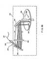
- FIG. 6shows an exemplary light source 100' which may, for example, be adapted for use as a frequency swept source (such as frequency swept source 100 described above with reference to FIG. 5 ) is provided from an optical filter 170, coupled through a lens 172 and a light path 174 to a light source/controller 176 (hereinafter referred to as "light controller 176").
- the light controller 176may, in turn, be coupled to one or more applications 178.
- the applications 178may, for example, correspond to optical imaging processes and/or optical imaging systems, laser machining processes and systems, photolithography and photolithographic systems, laser topography systems, telecommunications processes and systems.
- the exemplary light source 100' provided from the filter 170 and the light controller 176may be used in a wide variety of different applications, certain general examples of which are described herein.
- the filter 170allows the light source 100' to operate as a frequency swept source which emits a spectrum of which the center wavelength can be tuned continuously and repeatedly in time across the bandwidth of the light controller 176.
- light source 100'may have an instantaneous emission spectrum comprised of a plurality of frequency modes of the light source/controller 176.
- the optical wavelength filter 170is configured as a reflection-type filter in that the input and output ports are identical.
- light path 174may be provided, for example, as an input/output optical fiber and lens 172 may correspond to a collimating lens.
- the light controller 176can include a number of systems that are specifically adapted to transmit a beam of light (in one embodiment, a collimated beam of light) having a broad frequency (f) spectrum.
- the beam of lightcan include a plurality of wavelengths, within the visible light spectrum (e.g., red, blue, green).
- the beam of light provided by the light controllercan also include a plurality of wavelengths that are defined outside of the visible spectrum (e.g., infrared).
- the light controller 176can include a unidirectional light transmission ring.
- the light controller 176can include a linear resonator system.
- the filter 170includes a wavelength dispersing element 180 adapted to receive the beam of light from the light controller 176 and to separate the beam of light into a plurality of different wavelengths of light each directed along a light path as is known.
- the wavelength dispersing element 180can include one or more elements adapted to receive the beam of light from the light controller 176, and to separate the beam of light into a plurality of wavelengths of light each directed along a light path.
- the wavelength dispersing element 180is further operative to direct the plurality of wavelengths of light in a plurality of angular directions or displacements with respect to an optical axis 182.
- the wavelength dispersing element 180can include a light dispersion element, such as a reflection grating 184.
- the wavelength dispersing element 180could alternatively be provided as a transmission grating (e.g. a transmission type grating such as Dickson-type holographic grating), a prism, a diffraction grating, an acousto-optic diffraction cell or combinations of one or more of these elements.
- the wavelength dispersing element 180directs light at each wavelength towards a lens system 186 along paths which are at an angle with respect to the optical axis 182. Each angle is determined by the wavelength dispersing element 180.
- the lens system 186can include one or more optical elements adapted to receive the separated wavelengths of light from the wavelength dispersing element 180 and to direct or steer and/or focus the wavelengths of light to a predetermined position located on a beam deflection device 188.
- the beam deflection device 188can be controlled to receive and selectively redirect one or more discrete wavelengths of light back along the optical axis 182 through the lens system 186 to the wavelength dispersing element 180 and back to the light controller 176.
- the beam deflecting device 188can be formed and/or arranged in a number of ways.
- the beam deflecting device 188can be provided from elements including, but not limited to, a polygonal mirror, a planar minor disposed on a rotating shaft, a minor disposed on a galvanometer, or an acousto-optic modulator.
- the dispersing element 186includes a diffraction grating 184, a lens system 186 (which has first and second lenses 190, 192 to form a telescope 193), and the beam deflecting device 188 which is shown as a polygon mirror scanner 194.
- the telescope 193is provided from the first and second lenses 190, 192 with 4- f configuration.
- the first and second lenses 190, 192 of the telescope 193are each substantially centered on the optical axis 182.
- the first lens 190is located at a first distance from the wavelength dispensing element 180 (e.g., diffraction grating 184), which is approximately equal to the focal length F1 of the first lens 190.
- the second lens 192is located a second distance from the first lens 190, which is approximately equal to the sum of the focal length F1 of the first lens 190 and the focal length F2 of the second lens 192.
- the first lens 190can receive the collimated discrete wavelengths of light from the wavelength dispersing element 180, and may effectively perform a Fourier Transform on each one of the collimated one or more discrete wavelengths of light to provide an equal one or more converging beams projected onto an image plane (see designated IP of FIG. 6 ).
- the image plane IPis located between the first and second lenses and at a predetermined distance from the first lens, which predetermined distance is defined by the focal length F1 of the first lens.
- the converging beam(s)After propagating through the image plane IP, the converging beam(s) form an equal one or more diverging beams that are received by the second lens.
- the second lensoperates to receive the one or more diverging beams and to provide an equal number of collimated beams having predetermined angular displacements with respect to the optical axis 182 for directing or steering the collimated beams to predefined portions of the beam deflection device 188.
- the telescope 193is configured to provide a number of features, as described above, and further to convert diverging angular dispersion from the grating into converging angular dispersion after the second lens 192, which is desired for proper operation of the filter 170.
- the telescope 193provides a useful degree of freedom, which controls the tuning range and reduces the beam size at the polygon mirror 194 to avoid a beam clipping.
- the polygon mirror 194reflects back preferably only the spectral component within a narrow passband as a function of the angle of the front mirror facet of the polygon with respect to the optic axis.
- the reflected narrowband lightis diffracted and received by the optical fiber 174.
- the orientation of the incident beam with respect to the optic axis and the rotation direction 198 of the polygon mirror 194determine the direction of wavelength tuning: wavelength up (positive) scan or down (negative) scan.
- the arrangement in FIG. 6produces a positive wavelength sweep.
- the mirror 194is shown in FIG. 6 as having twelve facets, fewer or more than twelve facets can also be used. The particular number of facets to use in any application depends upon the desired scanning rate and scanning range for a particular application. Furthermore, the size of the mirror is selected in accordance with the needs of a particular application taking into account factors including, but not limited to, manufacturability and weight of the mirror 194. It should also be appreciated that lenses 190, 192 may be provided having different focal lengths. The lenses 190, 192 should be selected to provide a focal point at approximately the center point 200 of the mirror 194.
- ⁇p ⁇ (sin ⁇ + sin ⁇ ) where ⁇ is the optical wavelength, p is the grating pitch, and ⁇ and ⁇ are the incident and diffracted angles of the beam with respect to a nominal axis 202 of the grating, respectively.
- Tuning range of the filteris fundamentally limited by the finite numerical aperture of lens1 20.
- An importance design parameter of the filter, originated from multiple facet nature of the polygon mirror,is the free spectral range, which is described in the following.
- the tuning range of the lasercannot exceed the free spectral range if the gain medium has homogenous broadening, since the laser chooses the wavelength of highest gain.
- the duty cycle of laser tuning by the filtercan be, in principle, 100% with no excess loss caused by beam clipping if two necessary conditions are met as follows: W ⁇ cos ⁇ F 1 cos ⁇ 0 ⁇ F 2 ⁇ L and W ⁇ cos ⁇ cos ⁇ 0 ⁇ F 2 - S ⁇ ⁇
- the first equationis derived from the condition that the beamwidth after lens 192 should be smaller than the facet width.
- the second equationis from that the two beams at the lowest and highest wavelengths 204, 206 respectively of the tuning range should not overlap each other at the polygon mirror S in Equation (1) denotes the distance between the lens 192 and the front mirror of the polygon.
- the characteristics of the filterwere measured using broadband amplifier spontaneous emission light from a semiconductor optical amplifier (SOA) and an optical spectrum analyzer.
- SOAsemiconductor optical amplifier
- the optical spectrum analyzerrecorded the nonnalized throughput (reflected) spectrum in peak-hold mode while the polygon mirror was spinning at its maximum speed of 15.7 kHz.
- the measured tuning rangewas 90nm which is substantially smaller than the theoretical value of 126nm.
- the discrepancywas due to the aberration of the telescope, primarily field curvature, associated with relatively large angular divergence of the beam from the grating. It is expected that the aberration would be improved by using optimized lenses.
- the free spectral rangewas 73.5nm in agreement with the theoretical calculation.
- the FWHM bandwidthwas measured to be 0.12nm. The discrepancy with theoretical limit of 0.11nm may be reasonable considering the aberration and imperfection of the optical elements.
- FIG. 7shows an extended-cavity semiconductor laser 208 according to an exemplary embodiment of the present invention which can include a filter 210 that may, for example, be similar to the filter 170 described above with reference to FIG. 6 .
- the filter 210is coupled through a light directing element 212 and a light path 214 to a Faraday circulator 216.
- the filter 210includes a grating 232 and a polygonal mirror 236.
- the filter 210may correspond to a polygon-based filter.
- a motor 234drives the mirror.
- the Faraday circulator 216 of this exemplary embodimentis coupled through polarization controllers 220, 222 to a gain medium 224 which in one exemplary embodiment can be a semiconductor optical amplifier (e.g., SOA, Philips, CQF 882/e) having coupled thereto a current source 226 which provides an injection current to the SOA 224.
- the intracavity elementsmay be connected by single-mode optical fibers, for example.
- the two polarization controllers 220, 222can align the polarization states of the intracavity light to align to the axes of maximum efficiency of the grating 232 and of maximum gain of the SOA 224.
- a laser output 228may be obtained through a 90% port of a fiber-optic fused coupler 230.
- 5% of the laser outputmay be coupled through a variable wavelength filter 237 having a bandwidth of 0.12nm and is directed toward a photodetector 238.
- the center wavelength of the filtermay be fixed at 1290nm.
- the detector signalgenerates short pulses when the output wavelength of the laser is swept through the narrowband passband of the fixed-wavelength filter. The timing of the sync pulse is controlled by changing the center wavelength of the filter.
- FIG. 8Ashows a graph 240 of an output spectrum of a laser of the type described above with reference to FIG. 7 as measured by an optical spectrum analyzer in peak-hold mode, when the polygon mirror (i.e. mirror 236 in FIG. 7 ) spins at a rate of 15.7 kHz.
- the edge-to-edge sweep rangemay be from 1282nm to 1355nm over 73nm-width equal to the free-spectral range of the filter.
- the Gaussian-like profile of the measured spectrum, rather than a square profile,is likely due to the polarization-dependent cavity loss caused by polarization sensitivity of the filter and the birefringence in the cavity. It is preferable to adjust the polarization controllers to obtain the maximum sweep range and output power.
- FIG. 8Bshows a curve 242 of a laser output in a time domain.
- the upper trace 244corresponds to a sync signal obtained through the fixed-wavelength filter.
- the amplitude of power variation from facet to facetwas less than 3.5%.
- the peak and average output powerwas 9mW and 6mW, respectively. It should be mentioned that the y-axis scale of curve 240 had to be calibrated from the time-domain measurement, because the optical spectrum analyzer only recorded a time-averaged spectrum due to the laser tuning speed much faster than the sweep speed of the spectrum analyzer.
- a frequency downshift in the optical spectrum of the intracavity laser lightmay arise as the light passes through an SOA gain medium (e.g. SOA 224 in FIG. 7 ), as a result of intraband four-wave mixing phenomenon.
- the positive wavelength scancan facilitate tuning of the laser spectrum, and thereby produce higher output powers.
- the peak power of the laser outputcan be measured as a function of the tuning speed.
- the negative tuning speedmay be obtained by flipping the position of the collimator and the orientation of the grating with respect to an optic axis (e.g., axis 182 in FIG. 6 ). It is preferable to make the physical parameters of the filter approximately identical in both tuning directions.
- the combined action of self-frequency shift and positive tuningallows higher output to be obtained and enables the laser to be operated at higher tuning speed. Therefore, the positive wavelength scan may be the preferred operation.
- the output powermay decrease with increasing tuning speed.
- a short cavity lengthmay be desired to reduce the sensitivity of the output power to the tuning speed. In this case, a free-space laser cavity is preferred.
- FIG. 9Ashows an exemplary embodiment of a free-space extended-cavity semiconductor tunable laser 250 according to an exemplary embodiment of the present invention that includes a semiconductor waveguide 252 fabricated on a substrate chip 254 coupled to a polygon scanning filter 255 through a collimating lens 256.
- a front facet 258may be anti-reflection coated, and an output facet 260 is cleaved or preferably coated with dielectrics to have an optimal reflectivity.
- An output 262 of the laseris obtained through the output coupling lens 264.
- the collimating lenses 256, 264are preferably provided as aspheric lenses.
- the filter 255includes a wavelength dispersing element 180' adapted to receive the beam directed thereto from the lens 256.
- the wavelength dispersing element 180'may be similar to wavelength dispersing element 180 described above with reference to FIG. 6 .
- a lens system 186'can be disposed between the wavelength dispersing element 180' and a beam deflection device 188'.
- the wavelength dispersing element 180' and a beam deflection device 188'may be similar to wavelength dispersing element 180 and a beam deflection device 188 described above with reference to FIG. 6 .
- the lens systems 186'includes a pair of lenses 187a, 187b which are preferably provided as achromats having low aberration particularly in field curvature and coma.
- a sync outputmay be obtained by using a lens 266, a pinhole 268, and a photodetector 270 positioned on the 0-th order diffraction path for the light which is on retro-reflection from a polygon scanner 272.
- the detectorgenerates a short pulse when the focus of the optical beam of a particular wavelength sweeps through the pinhole 268.
- Other types of gain mediummay include, but are not limited to, rare-earth-ion doped fiber, Ti:Al 2 O 3 , and Cr 4+ :forsterite.
- FIG. 9Bshows another exemplary embodiment of a wavelength tunable filter 280 according to the present invention which may include an optical fiber 281 coupled to an input collimating lens 282, optically coupled to a diffraction grating 284, a focusing lens 286, and a spinning disk 288.
- the diffraction grating 284may be replaced by other angular dispersive elements such as a prism.
- the diffraction grating 284can have a concave curvature with a focal length selected such the focusing lens 286 is not needed.
- the reflectors 290may be deposited on a surface 288a of the spinning disk 288.
- the reflectors 290comprise multiple narrow stripes periodically and radially patterned.
- the material for the reflectorsis preferably gold.
- the disk 288can be composed of a lightweight plastic or silicon substrate. Instead of the reflectors deposited on the top surface of the disk, the disk can have a series of through holes followed by a single reflector attached to the back surface of the disk.
- the optical beams of different wavelengthsmay be illuminated on the surface of the disk into a line after being diffracted by the grating and focused by the lens 286 (in those systems which include lens 286).
- the lens 286in those systems which include lens 286).
- only the beam that impacts the reflectors of the spinning diskmay be retro-reflected and received by the optical fiber 281.
- a mirror 292may be used to facilitate the access of the beam onto the disk.
- filter bandwidthbecomes greater, and for w ⁇ w s , the efficiency (reflectivity) of the filter is decreased by beam clipping.
- the orientation of an incident beam 294 with respect to the optic axis of the lens 286 and the spinning direction 288preferably determines the sense of wavelength tuning.
- the positive wavelength scanis preferable, which is achieved by spinning the disk 288 in a clockwise direction as shown in FIG. 9B .
- FIG. 10Ashows an exemplary embodiment of an OFDI system 300 for performing optical imaging using frequency-domain interferometry includes a frequency swept source 301 which emits a light signal having an instantaneous emission spectrum comprised of a plurality of frequency modes of the light source.
- Source 301may, for example, be provided as one of the sources described above with reference to FIGS. 4A , 5 , 6 , 7 , 9 and 9B .
- the light from source 301can be directed toward a fiber-optic coupler 302 which divides the light fed thereto into a reference arm 303 and a sample arm 304.
- the reference arm 303preferably includes a polarization circuit 306 and a circulator 308.
- the optional motion artifact circuit 309may be provided from a lens 310 which directs the light toward a frequency shifter 311, a phase tracker 312 and a dispersion compensator 314. The light passes through optional circuit 309 and is incident upon a reference mirror 316.
- circuit 309functions to remove or reduce motion artifacts.
- circuit 309may include all of the elements 310-314, and/or one or more of the circuit elements 310-314.
- the sample arm 304may include a circulator 318.
- a light signal transmitted from the source 301propagates from source 301 through the coupler 302 and the circulator 308 to a lens 320 which directs the light toward a scanning mirror 322.
- the scanning mirror 322may be provided from a wide variety of optical elements including but not limited to, a galvanometer, a piezoelectric actuator or another functionally equivalent device.
- a transverse scanner 324is coupled to the scanning mirror 322 and a data acquisition board and computer 326. The data acquisition board and computer 326 is also coupled to the frequency swept source 301.
- the OFDI system 300 shown in FIG 10Acan also include a polarization diversity balanced detection (“PDBD”) circuit 334 configured to receive signals from the reference arm 303 and/or the sample arm 304.
- PDBDpolarization diversity balanced detection
- the reference arm 303is connected through circulator 308 and polarization control circuit 330 to a reference port of the PDBD circuit 334.
- sample arm 304is connected through circulator 318 and polarization control circuit 332 to a sample port of the PDBD circuit 334.
- the sample arm 304collects light reflected from a tissue sample 328 and is combined with the light from the reference arm 303 in the polarization diversity balanced detection (PDBD) circuit 334 to form interference fringes.
- PDBDpolarization diversity balanced detection
- the OFDI techniquedoes not require that the optical path length in the reference arm be scanned in time.
- Such fixed delay reference armsmay have various configurations that are known to those having ordinary skill in the art.
- the reference arm 303can be either of reflective and/or transmission type, and can return light back from the mirror 316. The returned light is directed toward the polarization control circuit 330 via the circulator 308. Similarly, the reflected light from the sample 338 can be directed toward a polarization control circuit 332 via the circulator 318. The reference arm can also be transmission with no reflection.
- the polarization control circuit 330can be used to match the polarization state of the reference-arm light to that of the sample-arm. The total birefringence in the interferometer should be minimized not to induce wavelength-dependent birefringence.
- the polarization controllermay include, but is not limited to, a fiber-optic polarization controller based on bending-induced birefringence or squeezing.
- the chromatic dispersionshould be matched substantially between the reference and sample arm.
- the result of strong dispersion mismatchmay be a loss in the axial resolution.
- Any residual dispersioncan likely be compensated by appropriate signal processing, such as nonlinear mapping based on interpolation of the detector data before the Fourier transform. This mapping may also be accomplished, at least in part, by adjusting the optical layout of the wavelength-swept source.
- the source 301includes a polygon scanner and a telescope
- the distance between the polygon scanner and the telescopecan be adjusted to convert wavelength space to wave vector space prior to Fourier transformation.
- the sample armmay be terminated by an optical probe comprising a cleaved (angled, flat, or polished) optical fiber or free space beam.
- a lens 336(such as, but not limited to, aspherical, gradient index, spherical, diffractive, ball, drum or the like) may be used to focus the beam on or within the sample.
- Beam directing elements(such as, but not limited to, mirror, prism, diffractive optical element or the like) may also be contained within the probe to direct the focused beam to a desired position on the sample.
- the position of the beammay be changed on the sample as a function of time, allowing reconstruction of a two-dimensional image. Altering the position of the focused beam on the sample may be accomplished by the scanning mirror 322.
- the scanning mirror 322may be provided, for example, from a number of different devices including, but not limited to, a galvanometer, piezoelectric actuator, an electro-optic actuator or the like.
- the sample arm probemay be a fiber optic probe that has an internally moving element, such that the motion is initiated at a proximal end of the probe and the motion is conveyed by a motion transducing arrangement (such as, but not limited to, wire, guidewire, speedometer cable, spring, optical fiber and the like) to the distal end.
- the fiber optic probemay be enclosed in a stationary sheath which is optically transparent where the light exits the probe at the distal end.
- scanning wayalso be accomplished by moving the optical fiber. For example, by rotating the optical fiber, or linearly translating the optical fiber.
- 10Bshows an exemplary embodiment of the probe 359 which includes an inner cable 360 (that may rotate or linearly translate along the axis of the probe), an outer transparent or semi-transparent sheath 362, distal optics 364, and remitted light 366 (which may be at any angle with respect to axis of catheter).
- the detectors 370may preferably include photodiodes (such as, but not limited to, silicon, InGaAs, extended InGaAs, and the like). Balanced detection can be implemented by subtracting diode signals that are exactly out of phase with respect to the maxima and minima pattern. The difference between two detector signals is obtained by a differential circuit included in PDBD circuit 334 and amplified by trans-impedance amplifiers ("TIA") 360.
- TIAtrans-impedance amplifiers
- the dual balanced receivermay be further followed by a low-pass or band-pass filter to reject noise outside the detection bandwidth.
- the dual balanced detectioncan be implemented as follows.
- the polarization beam splitter 362receives signals from the reference and sample arms and provides two output signals.
- the two output signalsare further split by two non-polarizing beam splitters 364a, 364b, respectively.
- the outputs from each beam splitter 364a, 364bare detected by a dual balanced receiver provided from the four detectors 370.
- the two outputs of the dual balanced receiversare digitized and processed in a computer arrangement to obtain a polarization diversity.
- the receiver outputis provided to circuit 326 which acquires and digitizes the signals fed thereto via A/D converters, and stores the digitized signals in a computer for further processing.
- the bandwidth of the TIAis preferably matched to half the sampling rate.
- Gain of the TIAis preferably selected such that the maximum receiver output range is matched to the voltage range of the A/D converter.
- the signalscan be selectively subtracted and complex spectral density can be obtained.
- the complex cross spectral densitycan be converted to a depth profile in the tissue.
- Several methods to process the complex spectral density to obtain depth profile informationare known to those skilled in the art, such as, but not limited to, by obtaining at least two signals with a Pi/2 phase shift in the reference arm and then reconnecting the complex spectral density by some linear combination of the two signals, or by squaring the spectral density.
- analog processingcan include a trans-impedance amplifier, low pass (band pass) filter, and digitization of the signal. This signal may then be converted to reflectivity as a function of depth by the Fourier transform operation.
- Digital processingincludes digitization, digital band pass filtering in either the frequency domain or time domain (FIR or IIR filter) and inverse Fourier transformation to recover the tissue reflectivity as a function of depth.
- the detected non-linear wavelength coordinatesis preferably converted to regularly sampled wave-vector space.
- zero padding the signal, Fourier transformation, and inverse Fourier transformation with re-samplingcan be utilized for remapping.
- Other interpolation methods known in the art, such as linear, bi-linear, and cubic spline interpolation of the datamay also be used to convert wavelength space into regularly sampled k space. This mapping may also be accomplished in part by adjusting the optical layout of the wavelength-swept source. In one example, the distance between the polygon scanner and the telescope may be adjusted to convert wavelength space to wavevector space prior to Fourier transformation.
- Another exemplary embodiment of the present inventioncan utilize one or more techniques described below to further enhance the performance and functionality of imaging. These techniques are not limited to the OFDI techniques that use a multiple-frequency-mode tuned source, but can be applied in the OFDI technique using a single-frequency tuned source.
- polarization diversity schemeFor an application where polarization fading is a problem, a polarization diversity scheme may be used. Various configurations for polarization diversity are known in the art.
- the polarization diversity circuitoperates as follows.
- the polarization beam splitter 362separates the reference-arm and sample-arm light signals depending upon their polarization states.
- the polarization controller 330is preferably adjusted so that the reference-arm power is split with an equal magnitude by the polarization controller.
- the polarization state of the sample arm powercan be assumed to vary randomly due to the probe or sample motion, therefore the separating ratio of the sample arm power by the polarization splitter can vary in time.
- the two output signals at the two output ports of the polarization beam splitter 362can be detected by a photo receiver, e.g., squared and summed. The resulting signal is independent of the polarization state of the sample arm light.
- the frequency shiftercan be, but not limited to, an acousto-optic frequency shifter. In the detection, a proper electronics should be used to demodulate the carrier frequency.
- FIG. 10Cshows a graph 380 depicts the fringe visibility curve given by the instantaneous output spectrum of the source.
- the visibility curvehas a Gaussian profile if the source's instantaneous spectrum is Gaussian.
- a curve 390depicts the transmission efficiency profile of an electrical filter, which is optimized for a given Nyquist frequency defined as the half of the sampling frequency.
- Section (a) of FIG. 10Cshows a typical case where there is no frequency shifter in the interferometer and the electrical filter is a low pass filter.
- the transmission efficiency curve of the filter, 390has an exponentially-rising (falling) slope in its low frequency band.
- This filtermay be useful in which attenuation is significant and the resulting signal strength decays with depth.
- the slope filtercan improve the dynamic range of the detection by effectively suppressing the large signal from the surface relative to that at greater depths.
- a fixed-delay reference armcan be made in various configurations that are known to those having ordinary skill in the art.
- the reference armcan be of either reflective or transmission type.
- the capability of varying the optical delay in the reference armmay be useful when a larger ranging depth is desired, without increasing the data acquisition rate or reducing the instantaneous linewidth of the optical source.
- Such abilityis useful in a clinical study where the distance from the imaging lens and the front surface of the sample can varies significantly. Such variation can result from the motion or from the uncontrolled position of a probing catheter.
- a rotating catheter inside a blood vesselcan have distance variation by a couple of millimeter over a single A-scan.
- a mechanism in the reference arm 303may allow for scanning the group delay of the reference arm 303.
- This group delaycan be produced by any of a number of techniques known to those having ordinary skill in the art, such as, but not limited to, stretching an optical fiber, free space translational scanning using a piezoelectric transducer, or via a grating based pulse shaping optical delay line.
- the delaycan be introduced by a non-mechanical or motionless arrangement.
- non-mechanicalwhat is meant is that there are no mechanically moving parts being utilized. The absence of the mechanically moving parts is believed to reduce the known deficiencies of using mechanical devices to introduce delay.
- the reference arm 303does not necessarily need to scan over the full ranging depth in the sample, and can preferably scan over at least a fraction of the ranging depth equal to one over the number of detectors (1/N). This scanning feature is different from the conventional delay scanning schemes used in the known LCI and OCT systems.
- the reference arm 303optionally has a phase modulator mechanism, such as but not limited to, an acoustooptic modulator, electro-optic phase modulator or the like, for generating a carrier frequency.
- Phase trackingis preferable performed to eliminate phase instabilities in the interferometer.
- Phase instabilitiescan cause individual interferometric fringes to shift in location. If detection is slow relative to the shifting of the fringes, the resulting averaging results in chirping of the interference signal.
- A-scan rate of 10 to 40 kHzresults in an effective integration time of 100 to 25 ⁇ s. Phase instabilities arising on a time frame shorter than the integration time should be compensated.
- Phase locking circuitryis commonly used in electronics, and is frequently used in radar and ultrasound. Active phase tracking can be implemented by modulating the interferometer path length difference at 10 MHz with an electro-optic phase modulator in the reference arm over a fraction of the wavelength.
- an error signalBy demodulating the intensity measured by one detector at the output of the interferometer at the frequency of the path length modulation, an error signal can be generated indicating in which direction the phase modulator should shift to lock onto a fringe amplitude maximum. By adding an offset to the phase modulator as determined by the error signal, the phase tracker actively locks onto a fringe maximum.
- the phase modulatorcan modulate the path length difference over a few wavelengths.
- the processing unitcan determine if the phase modulator has reached its range limit, and jump by a full wave in phase to maintain lock on a different fringe maximum. This approach exploits the fact that phase should be controlled only modulo 2 ⁇ .
- the processingdrives a slower component (e.g., the Rapid Scanning Optical Delay ("RSOD") line) to extend the path length range of the phase modulator/RSOD combination over several millimeters.
- RSODRapid Scanning Optical Delay
- Phase lockingcan be performed on a fringe maximum, minimum, or zero crossing, based on the type of mixing performed in the demodulation circuit.
- the autoranging mechanismmay, in one exemplary embodiment, include a processor unit for (a) obtaining a first scan line; (b) locating a surface location "S" of a sample; (c) locating an optimal scan range "R" of the sample; (d) modifying a reference arm delay waveform to provide an output; (e) outputting the output to a reference arm; (f) determining whether the image is complete; and/or (g) moving to the next scan line if the image is not complete or remapping the image using the surface S data and the waveform data stored in the memory storage device if the image is complete.
- a separate, preferably monochromatic, light sourcecan be transmitted into the interferometer.
- the separate source wavelengthmay be within the wavelength tuning range of the OFDI source or may be centered at a different wavelength than the OFDI source spectrum.
- the separate sourceis preferably of higher power, and may be combined with the source arm (using wavelength division, multiplexer, grating, prism, filter or the like) travel to the reference and sample arms and return back to the beam recombining element.
- the returned separate source lightcan then be separated from the OFDI light following transmission back through the beam recombining element (i.e. beam splitter output).
- a separation arrangementcan perform spectral separation by a dispersing element, such as a dichroic mirror, filter, grating, prism, wavelength division multiplexer or the like.
- the separate sourcewill be detected separately from the OFDI light using one or more detectors.
- the higher power provided by this separate sourcecan enable detection of a higher amplitude interference pattern, and provide an improved input to the phase tracker, thus enabling more stable phase tracking.
- FIG. 11an in vivo image of a subject's fingertip (300*500 pixels) acquired at an A-line scan rate of 15.7 kHz is shown using the exemplary embodiment of the system and process according to the present invention.
- the optical sensitivitywas measured to be about -100 dB.
- the SNRis superior to an equivalent TD OCT of the same A-line scan rate.
- the vertical line noisearises due to an un-optimized detection when there is a strong mirror-like reflection from the surface of the tissue, but should preferably be eliminated substantially by a detection optimization and/or an appropriate signal processing.
- FIG. 12shows another exemplary embodiment of a phase tracker system 600 having an extended phase lock range is provided. This done by combining a fast element 602 (which may be provided, for example, as an electro-optic (EO) phase modulator 602) to modulate the path length difference over a small range, and a slower element 604 (which may, for example, be provided as a Rapid Scanning Optical Delay (RSOD) line 604) to modulate the path length over an extended range.
- the detector 606 signalcan be mixed with the phase modulator modulation frequency 608 by a mixer 610 and low pass filtered (filter not shown) to generate an error signal.
- the processing unit 612preferably processes the error signal to generate an offset voltage, and adds this offset voltage to the modulation signal 608, so as to generate the output for the phase modulator driver 614.
- the processing unit 612can generate a signal to the RSOD 604 to provide extended range tracking of the phase over distances of several millimeters.
- Light source 616, fiber splitter 618, sample arm 620 and reference arm 622are shown, and are described herein.
- MixerS tsin ⁇ ⁇ ⁇ t ⁇ * cos ⁇ + ⁇ sin ⁇ ⁇ ⁇ ⁇ t ⁇ ;
- Mixer ⁇ 2 ⁇ ⁇ ⁇ C tcos 2 ⁇ ⁇ ⁇ t * cos ⁇ + ⁇ sin ⁇ ⁇ t ;
- Mixer ⁇ 2 ⁇ ⁇ ⁇ S tsin 2 ⁇ ⁇ ⁇ t * cos ⁇ + ⁇ sin ⁇ ⁇ t .
- the signal MixerS(t) and Mixer2 ⁇ C ( t )are proportional to sin( ⁇ ) and cos( ⁇ ), respectively, with ⁇ the position within a single oscillation of the fringe pattern.
- the mixer outputs MixerS ( t ) and Mixer2 ⁇ C ( t )are used as an error signal to generate an offset voltage to steer the phase modulator to a new center position that minimizes the error signal, and locks the interferometer output on a fringe maximum or minimum, or a zero crossing, respectively.
- the complex spectral densitycan now be determined by two consecutive tuning scans, one where the error signal sin( ⁇ ) is minimized, and the next where the error signal cos( ⁇ ) is minimized, resulting in a 90 degrees phase shift between the two interference patterns. Using this mixing arrangement, the complex spectral density can be obtained rapidly and without resorting to an additional mechanical arrangement for changing the phase of the reference arm light.
- Fig. 13shows a further exemplary embodiment of an OFDI system 700 which includes a phase tracker for providing balanced detection according to the present invention.
- a source 702provides an electro-magnetic radiation (e.g., light) which passes through a splitter 704, that sends part of the light to a sample probe 706 and the remainder of the light to a Rapid Scanning Optical Delay ("RSOD") line 708.
- RSODRapid Scanning Optical Delay
- phase modulator PM 710Light from the phase modulator PM 710 is transmitted through a splitter 712, and then through two additional splitters 714 and 716, a portion of the output of which is sent as balanced detection outputs to spectral detection units (not shown, but as described elsewhere herein) and the remainder of the output is sent to the phase tracker assembly 720.
- phase tracker detectors D 1 and D 2 , 722 and 724receive the partial output of the pair of splitters 714 and 716, which in turn send signal to a mixer 726 to generate an error signal.
- a processing unit 728processes the error signal, where the sum generation of offset voltage and adds this to the modulation signal 730 to generate the output for the phase modulator driver 732.
- Modulation signalshown at box 730, is forwarded to the mixer 726 and the processing unit 726.
- the fringe amplitudecould be too small for the phase tracker to lock.
- a secondary source with longer coherence lengthcan be coupled to the system 700, e.g., to provide a larger fringe amplitude to the phase tracker.
- FIGS. 14A-14Cshow an exemplary embodiment of a method for tracking phase in an imaging system begins in processing blocks 750 and 752 according to the present invention by measuring a signal received from the sample arm and then increasing a phase of the signal. Processing of this exemplary method then proceeds to block 754, in which a first signal partition of the signal defined as x 1 is measured at least one peak of the signal. In decision block 756, a determination is as to whether the signal defined as x 1 has been measured at least one peak of the signal. If in decision block 756, it is determined that the signal defined as x 1 has been measured at at least one peak of the signal, then processing returns to block 754 and the signal is again measured.
- decision block 756it is determined that the signal defined as x 1 has not been measured at at least one peak of the signal, then processing flows to a decision block 758, where a determination is made as to whether to adjust the signal.
- the adjustmentmay be, e.g., an increase or a decrease in the phase of the signal by an incremental amount as shown in blocks 760 and 762. Regardless of whether an increase or a decrease in the phase of the signal is made, processing returns to processing block 754, where a second signal partition of the signal is measured at its peak. Blocks 756-762 are then repeated for such measured signal. It should be noted that the functions of blocks 750-762 may be performed in parallel and/or series with other imaging processes.
- the adjustment of phase " ⁇ "can be defined as A(x 2 -x 1 ), where "A" is a constant and that the process of determining whether to increase or decrease the phase of the signal by an incremental amount may further comprise the substeps of (1) determining whether A(x 2 -x 1 ) is within range of the phase modulator; and (2) changing ⁇ by an amount equal to A(x 2 -x 1 ) if A(x 2 -x 1 ) is within the range or changing ⁇ by an amount equal to A(x 2 -x 1 )-m2 ⁇ if A(x 2 -x 1 ) is outside of the range, where M is an integer greater than 1.
- the methodmay optionally further comprise a substep (3) re-measuring signal x 1 .
- the data recorded by the detector in timemay not be sampled as a strictly linear function of the optical frequency ⁇ or wave number k.
- the Fourier transformcan link z and k space (or t and ⁇ ). Because of the non-linear sampling in k, the acquired spectrum is interpolated to create evenly spaced samples in the k domain.
- the tuning slope of the lasercould be adjusted in such a way that the light is samples in equal intervals in k space, such that the interpolation becomes obsolete.
- the detection timingcould be designed to sample the light evenly spread in the k domain, such that the interpolation becomes obsolete.
- dispersion in the sample and reference arm of the interferometershould preferably be balanced.
- Dispersion imbalancecan also be corrected by digital processing.
- Phase chirping induced by motionscan also be corrected by digital processing.
- the motion artifact correctionthe axial movement of the sample is measured, and a proper nonlinear mapping can be calculated from the velocity of the movement.
- interpolation techniquesare known to those having ordinary skill in the art. This includes, but is not limited to, simple two-point interpolation, FFT zero-padding followed by two-point interpolation, and rigorous interpolation with the sinc function dictated by the Nyquist theorem.
- An exemplary embodiment of the present inventionmay also provide a probe for locating atherosclerotic plaque in a blood vessel, comprising: an interferometer; a spectral separating unit which splits signal received from the interferometer into a plurality of optical frequencies; and a detector arrangement capable of detecting at least a portion of the optical frequencies received from the spectral separating unit.
- the maximum ranging depthcan likely be limited by the finite width of the coherence function of the laser output because the coherence length is often compromised to obtain higher tuning speed, higher output power, or wider tuning range.
- the finite coherence lengthmay cause the visibility of the interference fringe to decrease as the path length difference of the interferometer increases. This result in the degradation of SNR, and therefore limits the maximum ranging depth.
- the inability to distinguish between a positive and negative electrical frequency in a conventional interferometrymay lead to the ambiguity between positive and negative depths.
- the reference delay of the interferometershould be adjusted so that the image presents at only either positive or negative depth. This further may limit the ranging depth for a given coherence length of the source.
- quadrature interference signalshave been measured based on active or passive phase biasing using a piezoelectric actuator, birefringence plate or 3x3 coupler. These techniques may provide otherwise overlapping images associated with positive and negative depths, but tended to leave significant residual artifacts due to the difficulty of producing stable quadrature signals. In this paper, we propose and demonstrate a simple technique that effectively eliminates the ambiguity between positive and negative depths.
- the exemplary technique according to the exemplary embodiment of the present inventionuses an optical frequency shifter in the interferometer to provide a constant frequency shift of the detector signal. This allows both sides of the coherence range to be used without crosstalk, and can double the ranging depth.
- the same concepthas been described above in the context of 1-dimensional optical frequency domain reflectometry using rotating birefringence plates at 58 Hz or a recirculating frequency shifting loop.
- an acousto-optic frequency shifteris used, and the technique is applied to high-speed OFDI with several orders of magnitude faster ranging speed.
- a signal processing technique according to a further exemplary embodiment of the present inventionis provided to accommodate a nonlinear tuning slope of the swept source in the frequency shifting technique.
- FIG. 15shows a high level diagram of an OFDI system which includes a wavelength-swept source 95, singlemode-fiber interferometer employing an optical frequency shifter 311 in a reference arm 80, a photodetector 88, and a signal processor 160.
- FIGS. 16(a) and 16(b)illustrate the effect of the frequency shift.
- the fringe visibility or the coherence functionhas a peak value at the zero depth and decrease as the depth increases.
- the coherence length Zcindicates the depth where the visibility drops to 0.5 and thereby the SNR drops by 6 dB.
- a single side of the coherence rangecan be used due to the sign ambiguity of the signal frequency (hatched region).
- both sides of the coherence range from -z c to z ccan be utilized without any image crosstalk between the negative and positive depths.
- Nonlinearity in v(t) with respect to timeresults in frequency chirping of the signal at a constant depth and causes the degradation of axial resolution.
- the detector signalmay be sampled with nonlinear time interval compensating for the frequency chirping.
- the detector signalcan be sampled with a constant time interval, and then the sampled data be mapped to a uniform v-space by interpolation prior to discrete Fourier transform ("DFT"). Both methods have been demonstrated to yield a transform-limited axial resolution. However, these methods are not applicable directly in the frequency shifting technique. Both the nonlinear sampling and interpolation method can result in artificial chirping of the frequency shift, leading to sub optimal axial resolution.
- a modified interpolation methodcan be used to achieve nearly transform-limited axial resolution over the entire ranging depth.
- the exemplary techniquemay be as follows:
- FIG. 17depicts the experimental setup of an exemplary OFDI system employing two acousto-optic frequency shifters (FS1 800 and FS2 802, Brimrose Inc. AMF-25-1.3) according to an exemplary embodiment of the present invention.
- the use of two frequency shiftersbalanced the material dispersion of the acousto-optic crystals automatically.
- the insertion loss of each device including fiber couplingmay be less than 2.5 dB.
- the sampling rate of the digitizercan be 10 MHz.
- the probe 810may include a galvanometer mirror and an imaging lens produced a probe beam with a confocal parameter of 1.1 mm.
- An optical tap coupler 820can be used in conjunction with a narrowband filter 830 and a photodetector 834 to generate a TTL trigger signal in an electrical circuit 836.
- the TTL signalmay be used as a trigger in analog to digital conversion.
- the interference signalcan be measured using a dual balanced receiver 151.
- the detector signalwas further processed prior to digitization using a low pass electrical filter 840.
- Other types of electrical filterssuch as a band pass filter and a slope filter.
- the transmission of the slope filtermay have an exponentially-rising (falling) slope in its low frequency band. This filter may be useful in which attenuation is significant and the resulting signal strength decays with depth.
- the slope filtercan improve the dynamic range of the detection by effectively suppressing the large signal from the surface relative to that at greater depths.
- the sampled data acquired at each depthwas processed with and without the mapping process.
- FIGS. 18(a) and 18(b)show exemplary results, where the y-axis represents the square of the DFT amplitudes normalized to the value at zero frequency, and the bottom and top x-axes represent the signal frequency and the depth z, respectively.
- the point spread functionsuffers from significant broadening and large degradation of the peak power as the depth increases, because of the nonlinearity of our swept laser [see FIG.
- 18(c) and 18(d)show the point spread functions measured with and without the mapping process, respectively.
- the peak of the signal power occurring at the zero depth present at a frequency of 2.5 MHzis at least approximately equal to the net acousto-optic frequency shift.
- the nearly transform-limited axial resolution observed in FIG. 18(d)validates the mapping technique.
- the reduction in the signal poweris less than 5 dB over the entire depth span of 5.8 mm, demonstrating the benefit of the frequency shifting technique in terms of extending the ranging depth.
- Each imagewas obtained using the mapping technique described above.
- the surface of the tissuewas placed with an angle with respect to the probe beam axis, and the reference mirror was positioned such that the signal was present at both positive and negative depths in the image.
- the tissue imageis contained within the effective ranging depth of 2.8 mm, i.e. the top half of the total depth span.
- the relatively large variation in the sample locationresulted in the imaging folding artifact.
- Bthe entire positive and negative depths could be displayed without ambiguity taking advantage of the ranging depth increased to 5.8 mm by the frequency shifting technique.
Landscapes
- Physics & Mathematics (AREA)
- General Physics & Mathematics (AREA)
- Spectroscopy & Molecular Physics (AREA)
- Health & Medical Sciences (AREA)
- Optics & Photonics (AREA)
- Life Sciences & Earth Sciences (AREA)
- Engineering & Computer Science (AREA)
- Electromagnetism (AREA)
- General Health & Medical Sciences (AREA)
- Nonlinear Science (AREA)
- Pathology (AREA)
- Condensed Matter Physics & Semiconductors (AREA)
- Animal Behavior & Ethology (AREA)
- Veterinary Medicine (AREA)
- Heart & Thoracic Surgery (AREA)
- Public Health (AREA)
- Surgery (AREA)
- Biomedical Technology (AREA)
- Medical Informatics (AREA)
- Molecular Biology (AREA)
- Biophysics (AREA)
- Radiology & Medical Imaging (AREA)
- Nuclear Medicine, Radiotherapy & Molecular Imaging (AREA)
- Signal Processing (AREA)
- Plasma & Fusion (AREA)
- Power Engineering (AREA)
- Analytical Chemistry (AREA)
- Human Computer Interaction (AREA)
- Chemical & Material Sciences (AREA)
- Biochemistry (AREA)
- Immunology (AREA)
- Mathematical Physics (AREA)
- Investigating Or Analysing Materials By Optical Means (AREA)
- Instruments For Measurement Of Length By Optical Means (AREA)
Abstract
Description
- This application claims priority from
U.S. provisional application no. 60/514,769 filed on October 23, 2003 - The present invention relates generally optical imaging, and more particularly to method and apparatus for performing optical imaging using frequency-domain interferometry.
- As is known in the art, optical interferometric reflectometry is a powerful tool for performing non-invasive, high-resolution (∼10 µm), cross-sectional imaging of a biological or other sample, to visualize micro-structural optical properties such as reflection, absorption, scattering, attenuation, birefringence, and spectroscopic analysis. There are a number of interferometric imaging techniques that are known in the art. These techniques in general can be divided into two major categories: (i) time-domain technique, and (ii) frequency-domain technique.
- Low coherence interferometry ("LCI") is one of the time-domain techniques. This technique uses a scanning system to vary the reference arm length and acquire the interference signal at a detector. Then, the fringe pattern is demodulated to obtain the coherence envelope of the source cross correlation function. Optical coherence tomography ("OCT") is a technique for obtaining two- or three-dimensional images using LCI. OCT is described in
U.S. Pat. No. 5,321,501 issued to Swanson et al. Multiple variants of the OCT techniques have been described, but many suffer from less than optimal signal to noise ratio ("SNR"), resulting in non-optimal resolution, low imaging frame rates, and poor depth of penetration. Power usage is a factor in such imaging techniques. For example in ophthalmic uses, only a certain number of milliwatts of power are tolerable before thermal damage can occur. Thus, boosting power is not feasible to increase SNR in such environments. Nevertheless, it would be desirable to have an imaging method with superior SNR without appreciably increasing power requirements. - Insufficient SNR can also prevent the OCT technique from being used at a high frame rate which is important to avoid motion artifacts and overcome the short measurement time window available, for example, for in-vivo vascular imaging. Therefore, a way to improve SNR and imaging speed (e.g., the frame rate) is desired.
- Spectral interferometry, or spectral radar, is one of the frequency-domain imaging techniques. In spectral radar, the real part of the cross spectral density of sample and reference arm light is measured with a spectrometer. Depth profile information can be encoded on the cross-spectral density modulation.
- The use of spectral radar concepts to increase SNR of LGI and OCT has been described previously. This technique uses a charge coupled device ("CCD") with a large number of pixels (an order of 1,000) to reach scan ranges on the order of a millimeter. The fast readout of the CCD device makes high-speed imaging possible.
- There are, however, a number of disadvantages associated with using a CCD device. First, CCD devices are relatively expensive compared to a single-element photo-receiver. Secondly, the previously described method uses a single CCD to acquire the data. Since the charge storage capacity is limited, it requires a reduction of the reference arm power to approximately the same level as the sample arm power, giving rise to auto correlation noise on the sample arm light. In addition, since no carrier is generated, the 1/f noise will dominate the noise in this system. Thirdly, even with the short integration times of state of the art CCD technology, phase instabilities in the interferometer reduce fringe visibility of the cross spectral density modulation. This shortcoming makes the technique vulnerable to motion artifacts.
- Coherent frequency-modulated continuous-wave reflectometry (C-FMCW) is another frequency domain technique known in the art.
U.S. Patent Nos. 5,956,355 and6,160,826 issued to Swanson et al. describes an optical imaging method and apparatus using this technique. The previously described imaging method is based on using a continuously-tuned single-frequency laser as an optical source. The tuning wavelength range is required to be several tens of nanometers to achieve ranging resolution of less than 100 microns. The instantaneous linewidth of the laser must be less than approximately 0.1 nm to achieve a detection range on the order of 1.0 mm. The tuning rate should be greater than 10 kHz for high speed (e.g., video-rate) imaging. Although an external-cavity semiconductor laser can be configured to achieve mode-hop-free single-frequency tuning over several tens of nanometer, the tuning rate has been less than 1 Hz due to stringent requirement on mechanical stability. A way to overcome this speed difficulty is preferable. - It would, therefore, be desirable to provide a system and method to overcome the source availability and scan speed shortcomings of conventional LCI and OCT.
WO 98/35203WO 97/32182 WO 03/06 2802 A2 - An exemplary optical frequency domain imaging ("OFDI") system can include a multiple-frequency-mode (or multiple longitudinal or axial-mode) wavelength-swept laser source optically coupled to an interferometer containing a sample under study. The system can further include an arrangement which is configured to produce interferometric signals in quadrature between light reflected from a sample and a reference light and a detector disposed to receive the interferometric signals.
- With such exemplary particular arrangement, an OFDI system which can operate with source powers that are relatively low compared with source powers of conventional systems and/or which operate at acquisition rates which are relatively high compared with acquisition rates of conventional systems may be provided. The use of a swept source results in an imaging system having reduced shot noise and other forms of noise which allows for much lower source powers, or much higher acquisition rates than conventional systems. This can lead to an increased detection sensitivity which results in the ability to provide real time imaging. Such imaging speed can assist practitioners in gastrointestinal, ophthalmic and arterial imaging fields, where motion artifacts are a continuing problem. By increasing a frame rate while maintaining or improving the signal to noise ratio such artifacts can be minimized or in some cases eliminated. Exemplary embodiments may also enable the screening of large areas of tissues with OFDI and allows enables the use of clinically viable screening protocols.
- In one exemplary embodiment, the wavelength-swept laser can be provided that may use an optical band-pass scanning filter in the laser cavity to produce a rapidly-swept multiple-frequency-mode output. By using an optical band-pass scanning filter in the laser cavity, it is not necessary to tune the laser cavity length to provide synchronous tuning of the laser spectrum. In other words, it does not require tuning the longitudinal cavity mode of the laser at the same rate as the center wavelength of the laser.
- In another exemplary embodiment, the detector can be a dual-balanced receiver disposed to accept interferometric signals and to suppress the relative intensity noise in the interferometric signals.
- The gain in signal-to-noise ratio ("SNR") according 10 an exemplary embodiment is advantageous over time-domain approaches such as OCT via a performance of the signal processing in the Fourier-domain. The SNR enhancement is by a factor of N, the ratio of the depth range to the spatial resolution. The enhancement factor N can reach a few hundreds to several thousand. This increase in SNR enables the imaging by a factor of N times faster, or alternatively allows imaging at the same speed with a source that has N times lower power. As a result, the exemplary embodiment overcomes two important shortcomings of conventional LCI and OCT, e.g., source availability and scan speed. The factor N may reach more than 1,000, and allows construction of OFDI systems that can be more than three orders of magnitude improved from OCT and LCI technology currently in practice.
- The gain in SNR is achieved because, e.g., the shot noise has a white noise spectrum. The signal intensity present at the detector at frequency ω (or wavelength λ) contributes only to the signal at frequency ω, but the shot noise is generated at all frequencies. By narrowing the optical band width per detector, the shot noise contribution at each frequency can be reduced, while the signal component remains the same.
- Exemplary embodiments improve current data acquisition speeds and availability of sources compared with OCT. Shot noise is due to the statistical fluctuations of the current that are due to the quantized or discrete electric charges. The reduction of shot noise allows for much lower source powers or much higher acquisition rates. Limitations in current data acquisition rates (∼4 frames/sec) are imposed by available source power and availability of fast mechanisms for scanning delay. An increase in the sensitivity of the detection by a factor of 8 would allow real time imaging at a speed of about 30 frames per second. An increase of the sensitivity by a factor of about 1,000-2,000 allows for the use of sources with much lower powers and higher spectral bandwidths which are readily available, cheaper to produce, and can generate higher resolution OFDI images.
- For ophthalmic applications of OFDI, efficient detection preferably allows for a significant increase of acquisition speed. One limitation in ophthalmic applications is the power that is allowed to enter the eye according to the ANSI standards (approximately 700 microwatts at 830 nm). Current data acquisition speed in ophthalmic applications is approximately 100-500 A-lines per second. The power efficient detection technique would allow for A-line acquisition rates on the order of about 100,000 A-lines per second, or video rate imaging at about 3,000 A-lines per image.
- To achieve at least some of the goals of the resent invention, an apparatus and method according to
claim 1 and claim 17 is presented. For example, at least one first electro-magnetic radiation is provided to a sample and at least one second electro-magnetic radiation is provided to a reference. A frequency of the first and/or second radiations varies over time. An interference is detected between at least one third radiation associated with the first radiation and at least one fourth radiation associated with the second radiation. Alternatively, the first electro-magnetic radiation and/or second electro-magnetic radiation have a spectrum which changes over time. The spectrum may contain multiple frequencies at a particular time. In addition, it is possible to detect the interference signal between the third radiation and the fourth radiation in a first polarization state. Further, it may be preferable to detect a further interference signal between the third and fourth radiations in a second polarization state which is different from the first polarization state. The first and/or second electro-magnetic radiations have a spectrum whose mean frequency changes substantially continuously over time at a tuning speed that is greater than 100 Tera Hertz per millisecond. - Also, the third radiation is a radiation coming from the sample, and the at least one fourth radiation is a radiation coming from the reference. The frequency of the first, second, third and/or fourth radiation may be shifted. An image can be generated based on the detected interference. A probe may be used which scans a transverse location of the sample to generate scanning data, and provides the scanning data to the third arrangement so as to generate the image. The scanning data may include the detected interference obtained at multiple transverse locations on the sample. At least one photodetector and at least one electrical filter may be used which follow a photodetector, which is followed by an electrical filter. The electric filter may be a bandpass filter having a center frequency that is approximately the same as a magnitude of the frequency shift by the frequency shifting arrangement. A transmission profile of the electrical filter can vary substantially over its passband. The probe may include a rotary junction and a fiber-optic catheter. The catheter can be rotated at a speed higher than 30 revolutions per second. At least one polarization modulator may be provided.
- At least one polarization diverse receive and/or a polarization diverse and dual balanced receiver may be used. It is further possible to track the phase difference between:
- the first electromagnetic radiation and the second electromagnetic radiation, and/or
- the third electromagnetic radiation and the fourth electromagnetic radiation.
- Further, the first and second electro-magnetic radiations are emitted, at least one of which has a spectrum whose mean frequency changes substantially continuously over time at a tuning speed that is greater than 100 Tera Hertz per millisecond.
- An apparatus may include at least one first arrangement providing at least one first electro-magnetic radiation to a sample and at least one second electro-magnetic radiation to a reference. The apparatus may also include at least one second arrangement adapted for shifting the frequency of the first electro-magnetic radiation and the second electromagnetic radiation, and an interferometer interfering the first and second electro-magnetic radiations to produce an interference signal. Further, the apparatus may include at least one second arrangement detecting the interference between the first and second electro-magnetic radiations.
- Further, a system, method, software arrangement and storage medium can be provided for determining particular data associated with at least one of a structure and composition of a tissue. In particular, information associated with an interferometric signal is received which is formed from at least one first electro-magnetic radiation obtained from a sample and at least one second electro-magnetic radiation obtained from a reference. The first and/or second electro-magnetic radiations is/are frequency-shifted. The information is sampled to generate sampled data in a first format. Further, the sampled data is transformed into the particular data that is in a second format, the first and second format being different from one another.
- For a more complete understanding of the present invention and its advantages, reference is now made to the following description, taken in conjunction with the accompanying drawings, in which:
FIG. 1 is a block diagram of a time-domain optical coherence tomography ("OCT") system;FIG. 2 is a block diagram of a system which performs frequency-domain imaging using a spectral radar technique;FIG. 3A is a block diagram of a system which performs frequency-domain imaging using a coherent single-frequency tuning source according to one exemplary embodiment ;FIGS. 3B and 3C are graphs of wavelength versus amplitude which taken together illustrate the occurrence of a frequency shift generated by the system ofFig. 3A ;FIG. 3D is a graph of a beat signal generated by the system ofFIG. 3A ;FIG. 4A is a block diagram of a system which performs frequency-domain imaging using a multiple-longitudinal-mode wavelength-swept source according to another exemplary embodiment ;FIGS. 4B and 4C are graphs of a wavelength spectrum which taken together illustrate the occurrence of a shift in the spectrum generated by the system ofFig. 4A ;FIG. 4D is a graph of a beat signal generated by the system ofFIG. 4A ;FIG. 5 is a block diagram of a system which performs frequency-domain imaging using a wavelength-swept source according to another exemplary embodiment ;FIG. 6 is a block diagram of an optical wavelength tunable filter arrangement according to an exemplary embodiment of the present invention;FIG. 7 is a block diagram of a wavelength-swept laser arrangement according to an exemplary embodiment of the present invention;FIG. 8A is an exemplary graph of a laser output spectrum as measured at an output of the wavelength-swept laser arrangement ofFIG. 7 ;FIG. 8B is an exemplary graph of a laser output as measured at an output of the wavelength-swept laser ofFIG. 7 ;FIG. 9A is a block diagram of a wavelength tunable filter arrangement bearing a polygonal mirror according to yet another exemplary embodiment of the present invention;FIG. 9B is a block diagram of a wavelength tunable filter arrangement having reflective disk according to still another exemplary embodiment of the present invention;FIG. 10A is a block diagram of an optical frequency domain imaging ("OFDI") system which includes a wavelength-swept laser and a polarization diversity-balanced detection ("PDBD") circuit according to a further exemplary embodiment;FIG. 10B is a block diagram of an exemplary probe arrangement shown inFIG. 10A ;FIG. 10C is a plurality of graphs illustrating exemplary outputs of a carrier-frequency heterodyne detection using the system ofFIG. 10A ;FIG. 11 is an exemplary in-vivo image of a human finger tip obtained using exemplary embodiments;FIG. 12 is a block diagram of a phase tracker arrangement according to an exemplary embodiment;FIG. 13 is a block diagram of an exemplary embodiment of the OFDI system according to the present invention having the phase tracker;FIGS. 14A-14C are flow diagrams which illustrate an exemplary technique for a phase tracker operation according to the present invention;FIG. 15 is a simplified diagram of the OFDI system according to another exemplary embodiment;FIGS. 16(a) and 16(b) are graphs of effects of a frequency shift according to the present invention, i.e., depth versus signal frequency;FIG. 17 is a block diagram of the OFDI system employing two acousto-optic frequency shifters according to still another exemplary embodiment ;FIGS. 18(a) and 18(c) are graphs of point spread functions measured without a mapping process; andFIGS. 18(b) and 18(d) are graphs of point spread functions measured with a mapping process.- Throughout the drawings, the same reference numerals and characters, unless otherwise stated, are used to denote like features, elements, components, or portions of the illustrated embodiments. Moreover, while the present invention will now be described in detail with reference to the Figures, it is done so in connection with the illustrative embodiments.
FIG. 1 shows an exemplary prior art time domain optical coherence tomography ("OCT")system 10 which includes abroadband source 12 that provides a signal to afirst arm 14a of two-by-twosplitter 14. The splitter divides the signal provided thereto atport 14a, and provides a first portion of the signal at aport 14b coupled to areference arm 16. Thesplitter 14 also provides a second portion of the signal at aport 14c coupled to asample arm 18.- The
sample arm 18 terminates at asample volume 19 and anarrangement 22 for providing a lateral scan of the sample volume is disposed in thesample arm 18 prior to thesample volume 19. Thereference arm 16 terminates in anarrangement 20 for providing an axial scan. Thearrangements - Signals reflected from the
means 20 andsample volume 19 back along the reference and samplearms respective ports splitter 14 and are coupled to adetector 24 which producesaxial scan data 26 as is generally known.U.S. Patent 6,341,036 , describes systems similar to the one described above and shown inFIG. 1 . - In general, on scanning the reference
arm path length 16, interference fringes are formed corresponding to positions that match the distance to the threestructures sample volume 19. Thesingle detector 24 is used to detect the interference fringes. By envelope detection of the fringe patterns, animage 26 is constructed that maps tissue reflectivity to a given location. - As will be apparent from certain exemplary embodiments described herein below, an exemplary embodiment of the present invention relates to a system which utilizes a detection principle based upon Spectral Radar concepts (further referred to as Spectral Domain OCT) and/or a hybrid method between Spectral Domain and Time Domain OCT that is preferably more sensitive than current state of the art Time Domain OCT, allowing a substantial increase in the acquisition speed to resolution ratio.
- Analysis of the Signal to Noise Ratio ("SNR") in Time Domain OCT has been previously described in related publications. The interference fringe peak amplitude in time domain OCT is given by


- Assuming that the reference and sample spectral densities are equal to the source spectral densityS(ω), where the sample arm spectral density is attenuated by a large factor, i.e.,Sref(ω)=S(ω), Ssamp/e (ω)=αS(ω)with α 〈〈1, and inserting the above expression of reference and sample arm into the original definition of the signal gives,

- Three contributions to the total noise of OCT signals are: (i) thermal noise, (ii) shot noise and (iii) relative intensity noise. Thermal noise is generated by the feedback resistor, shot noise is related to the finite nature of the charge quantum resulting in statistical fluctuations on the current, and relative intensity noise is related to the temporal fluctuations due to chaotic character of classical light sources. These three contributions to the noise density in units [A2/Hz] are given by,


- The signal to noise ratio (SNR) is given by

- The best signal to noise performance of Time Domain OCT systems is obtained when the noise is shot noise limited. Shot noise can be reduced significantly by replacing the single element detector with a multi-element array detector. When the detection arm light is spectrally dispersed on the array detector, each element of the array detects a small wavelength fraction of the spectral width of the source. The shot noise is preferably reduced by a factor equal to the number of elements of the array. The principle of the signal to noise improvement is based on the white noise characteristic of shot noise and the observation that only electromagnetic waves of the same wavelength produce interference fringes.
- The shot noise power densityNnoise (f) (in units [W /Hz], [A2 /Hz ] or [V2 /Hz]) is proportional to the current (or equivalently the optical power times the quantum efficiency) generated in the detector. For a monochromatic beam of wavelength λI entering the interferometer, the fringe frequency or carrierf at the detector is determined by the velocityv of the mirror,f1, = 2v /λ1. The shot noise is proportional to the power (or spectral densityS(ω)) at wavelength λI. A second wavelength λ2 is preferably coupled into the interferometer. A second fringe frequency or carrier at frequencyf2= 2v/λ2 is simultaneously present. The shot noise at this second frequency is preferably the sum of the shot noise generated by the optical power at wavelength λ1 and λ2. Also, at frequencyf1 the shot noise is the sum of the shot noise generated by the optical power at wavelength λ1 and λ2. Thus, at both frequencies a cross-shot noise term is generated by the simultaneous presence of both wavelengths at the detector. By spectrally dispersing each wavelength to a separate detector, the cross shot noise term can be eliminated. In this way, Spectral Domain OCT offers a significant improvement of signal to noise ratio over Time Domain OCT systems.
- The OCT signal is most easily described in the space domain. For a single object in the sample arm, the interference term of the OCT signal is proportional to the real part of the Fourier transform of the source spectrumS(ω),


- The complex cross spectral density can also be obtained by splitting the signal I(t) in several spectral bands using a dispersive or interferometric element. At each detector, only part of the complex cross spectral density is determined. Combining the cross spectral densities of each detector, the full spectral density of the signal are retrieved. Thus, the same information can be obtained by separating spectral components to individual detectors. Combining the signal of all detectors in software or hardware would result in the same signal as obtained with a single detector.
- In the detection arm, the spectrum can be split into two equal halves, where two detectors each detect one half of the spectrum. According to Eq. (9), the frequency spectra at
detectors
|I1(f)| = S(πfc /v)for f <f0, I1 (f)=0 for f > f0 and
I2(f) = 0for f < f0,|I2 (f)| =S(πfc /v)for f > f0, respectively. The frequency spectrum as would be acquired by a single detector in time domain OCT is given by the sum ofI1 (f) andI2(f); I(f)= I1 (f)+ I2 (f). Thus, the signal S after combining the spectra is equal, howeverI1 (f)=0 forf > f0 andI2 (f)=0 forf <f0, the bandwidth BW per detector can be reduced by a factor of 2. - The noise is determined by the sum of the shot noise contributions at detectors one and two. From Eqs. (5) and (6), the shot noise per detector is proportional to the reference arm power at the detector times the bandwidth for the detector. Since the spectrum was split in equal halves, the reference power at
detectors 
- The sum of the shot noise contribution for the two detectors is,


- Thus, by spectrally dispersing the detection and light over two separate detectors, the signal remains the same, while the noise is reduced by a factor of 2, resulting in a net SNR gain by a factor of 2.
- Extending the above analysis, it can be demonstrated that the shot noise contribution is reduced by a factor equal to the number of detectors. The sum of shot noises for N detector elements, where each detector element receives one Nth of the total reference power, is given

- The signal is the same as in Time Domain OCT, and the SNR ratio for Spectral Domain OCT is given by,

- Thus Spectral Domain OCT enables a SNR improvement over Time Domain OCT of a hundred to a thousand fold, depending on the number of detector elements N. Using a charge coupled array or an integrating device as a detector, such as, but not limited to, a line scan camera, the ratio N/BCW is replaced by the integration time τi of the array, which results in,

FIG. 2 shows an exemplary SpectralDomain OCT system 100 which includes aninterferometer 102 with asource arm 104, asample arm 106, areference arm 108, and adetection arm 110 with aspectral separating unit 112, adetector array 114 comprised of a plurality of detectors and a like plurality ofamplifiers 116. Theamplifiers 116 are coupled through optional analog processing electronics (not shown, but known to those having ordinary skill in the art), and A/D converters (not shown, but known to those skilled in the art) for conversion of signals and through digital band pass filtering ("BPF")units 122 to a processing anddisplay unit 124.- The processing and
display unit 124 executes data processing and display techniques, and can optionally include the digital band pass filtering ("BPF")units 122 as well as Digital Fast Fourier Transforms ("'DFFTs") circuits (not shown), in order to provide coherent combination of signals and to perform the data processing and display functions. Thedetector array 114 may be 1 x N for simple intensity ranging and imaging and/or Doppler sensitive detection, 2 x N for dual balanced detection, 2 x N for simple intensity ranging and/or polarization and/or Doppler sensitive detection, or 4 x N for combined dual balanced and polarization and/or Doppler sensitive detection. Alternatively, an M x N array may be used for arbitrary number "M" ofdetectors 114 to allow detection of transverse spatial information on thesample 130. - Electro-magnetic radiation (e.g., light) is transmitted from the source along the
source ann 104 to the splitting unit via and is split between thereference arm 108 and thesample arm 106. The light propagates along the sample arm to thetissue sample 130 and through thereference arm 108 to a wavelength dependent phase arrangement. The light is reflected from the sample and the wavelength dependent phase arrangement back toward the splitting unit where at least portions of the reflected light are directed toward the spectral separating unit 112 (which may be provided as a grating for example). The detection arm light is dispersed by thespectral separating unit 112 and the spectrum is imaged onto thedetector array 114. By stepping thereference arm 108 length over a distance λ//8, the cross spectral density ofreference arm 108 andsample arm 106 light can be determined. The processing and display unit received the signals fed thereto and performs a Fourier transform of the cross spectral density to generate depth profile information. FIG. 3A shows a block diagram of an exemplary system which illustrates basic principles of a coherent frequency modulated continuous Wave ("C-FMCW") system using a single-frequency tuning source. Amonochromatic laser light 70 operable as a frequency chirped laser provides a light signal to an input 72a of acoupler 72. Thecoupler 72 divides the light signal into areference arm 80 which terminates in areference mirror 82 and asample arm 84 which terminates in asample 86. The light propagates downpaths reference mirror 82 andsample mirror 86 to provide, viacoupler 72, interference signals which are detected by a photo-detector 88.- As shown in graphs of
FIGS. 3B-3D , when there is an optical delay between two reflected light signals 90 (FIG. 3B ) and 92 (FIG. 3C ), respectively, a beat signal 94 (seeFIG. 3D ) having a frequencyf may be detected at thephoto detector 88. Where there are multiple reflection points in the sample along the axis, the interference consists of beat notes having frequencies which are proportional to the optical delay difference between the reflection (scatter) point in the sample and the reference mirror. The power of each beat frequency component is proportional to the reflectivity of the scatter. Therefore, the image of the sample can be constructed by Fourier transform of the interference data. - Referring now to
FIGS. 4A-4D , in which like elements described above and shown inFIGS 3A-3D are provided having the same reference designations, an optical frequency domain imaging ("OFDI") system according to an exemplary embodiment includes a wavelength-swept laser source 95 (also referred to herein as a frequency swept source 95) which provides a laser output spectrum comprised of multiple longitudinal modes to an input of acoupler 72. Thecoupler 72 divides the signal fed thereto into thereference arm 80 which terminates in thereference mirror 82 and thesample arm 84 which terminates in thesample 86. The optical signals reflect from thereference mirror 82 and thesample 86 to provide, viacoupler 72, a spectrum of signals which are detected by a photo-detector 88. - The center (or mean) wavelength of the signal spectrum is tuned in time by the creation of new longitudinal modes at the leading side of the spectrum and the annihilation of the modes at the trailing side of the spectrum.
- The same principles described above with reference to
FIGS. 3A-3D also apply to the OFDI technique using a wavelength-sweptlaser source 95. Similar to the case of a C-FMCW system (e.g., the system ofFIG. 3A described above), abeat signal 94 can be produced. In the case of the OFDI system that uses a wavelength-swept laser source, thebeat signal 94 can be generated having a beat frequencyf which corresponds to the difference in the center frequency of the lights, 96 and 98, from the reference and sample, respectively. - The frequency spacing between longitudinal modes should be substantially larger than the detection bandwidth. The mode beat frequency (relative intensity noise peaks) can be removed by a proper electronic filter, such as low pass filter, prior to digitization. The
interference signal 94 contains a frequency component that is proportional to the optical delay. Furthermore, the image of the sample can be constructed by Fourier transform of the digitized interference data. - In one exemplary embodiment of the present invention, the wavelength-swept
laser 95 can be provided which utilizes an optical band-pass scanning filter in the laser cavity to produce a rapidly-swept multiple-frequency-mode output. Exemplary filters according to the present invention is described below in conjunction withFIGS. 6 and9A . By using an optical band-pass scanning filter in the laser cavity, it is not necessary to tune the laser cavity length to provide synchronous tuning of the laser spectrum. Indeed, such arrangement does not require tuning the longitudinal cavity mode of the laser at the same rate as the center wavelength of the laser. - Using the OFDI techniques, a single pixel of the image can be constructed from the signal that is recorded as a function of time over the duration of one A-scan through Fourier transform. This is different from the TD OCT where a single pixel is constructed from the data measured at a short period time within one A-scan. The detection bandwidth to acquire the same number of data within the same A-scan period is approximately the same for both TD and FD OCT. However, the Fourier transform used for the OFDI technique effectively improves the signal-to-noise ratio compared to TD OCT by constructing a single image pixel from many data points acquired over the whole A-scan period. This effect can result in an ``effective" detection bandwidth that is N-times larger than the actual detection bandwidth. Therefore, the SNR may be improved by N times, where N is the number of (digitized) data points in the Fourier transform. It can be shown that SNR in a shot noise limited case is given by:

- Due to the narrowband output spectrum of the wavelength-swept source, however, the relative intensity noise (RIN) can be significantly higher than that of a CW broadband light source. For a thermal light, RIN is given by 1/Δv where Δv=c·Δλ/λ2 is the optical bandwidth of the (instantaneous) source output. For a laser light, RIN results from different statistics and therefore has a different value than the thermal light. For FD-OCT, a wavelength-swept laser with a low RIN level is preferred. The laser light with multiple longitudinal modes may have a similar RIN level as the thermal light with the same linewidth. In this case, a means to suppress the RIN is critical to have sufficient SNR, such as the dual balanced detection.
- Use of a swept source results in a system having reduced shot noise and other forms of noise which allows for much lower source powers, or much higher acquisition rates than current systems. The increased detection sensitivity allows for real time imaging. Such imaging speed can assist with a problem of motion artifacts, such as in gastrointestinal, ophthalmic and arterial imaging environments. By increasing the frame rate while maintaining or improving the signal to noise ratio such artifacts can be minimized. The present invention also enables one to screen large areas of tissues with the OFDI technique, and allows clinical viable screening protocols using this method.
- For ophthalmic applications of OFDI, the efficient detection preferably allows for a significant increase of acquisition speed. A possible limitation in ophthalmic applications is the power that is allowed to enter the eye according to the ANSI standards (approximately 700 microwatts at 830 nm). Current data acquisition speed in ophthalmic applications is approximately 100-500 A-lines per second. The power efficient detection would allow for A-line acquisition rates on the order of about 100,000 A-lines per second, or video rate imaging at about 3,000 A-lines per image.
- The gain in SNR is achieved because the shot noise has a white noise spectrum. The signal intensity present at the detector at frequency ω (or wavelength λ) contributes only to the signal at frequency ω, but the shot noise is generated at all frequencies. By narrowing the optical band width per detector, the shot noise contribution at each frequency can be reduced, while the signal component remains the same.
FIG. 5 shows an exemplary embodiment of asystem 99 for performing optical imaging using frequency-domain interferometry ("OFDI") which includes a frequency sweptsource 100 that emits a narrowband spectrum of which the center wavelength is tuned continuously and repeatedly in time across the bandwidth of the gain medium in the source. The instantaneous emission spectrum consists of a plurality of frequency modes of the light source. The frequency sweptsource 100, may be provided in a variety of different ways, some of which are described below. Thesource 100 may, for example, be provided from various gain media, tunable wavelength filters, cavity configurations. Devices and methods are known in the art to provide a rapidly-tuned wavelength-swept laser source, such as solid-state lasers, active-ion-doped waveguide lasers, and fiber lasers. A wavelength-swept laser in a mode-locked regime can also be used with potential advantage of a lower relative intensity noise (RIN) in a frequency region between harmonics of longitudinal-mode beat frequencies. An optical saturable absorber may be incorporated inside a laser cavity or after the output port of the source to lower RIN level.- The light provided from swept
source 100 is directed toward a fiber-optic coupler 102 which divides the light fed thereto into areference arm 103 and asample arm 104. In this exemplary embodiment, thecoupler 102 has a 90:10 power splitting ratio with 90% of the power being directed toward the sample arm. Those of ordinary skill in the art would understand, however, that other coupling ratios for thecoupler 102 may also be used. The particular coupling ratio to use in any particular application should be selected such that an amount of power is provided to both the reference arm and the sample arm to allow for proper operation of the exemplary system according to the present invention. - The power provided to the sample arm passes though a
circulator 111, and illuminates asample 136 to be imaged through a transverse-scanning imaging probe. The reference arm provides preferably a fixed optical delay. The lights reflected from areference mirror 124 and from within thesample 136 can be directed through therespective circulators - It is desirable that the combining
coupler 150 have an equal splitting ratio with minimal polarization dependence and wavelength dependence over the wavelength tuning range of the source. A deviation from equal splitting results in reduction of common mode rejection ratio ("CMRR") of the dual balanced detection. In one embodiment, the combiningcoupler 150 is preferably provided as a bulk broadband beam splitter. Those of ordinary skill in the art would understand that other types of couplers (including but not limited to wavelength-flattened fiber fused couplers) may also be used. - The interference signals are received by a dual
balanced receiver 151. Output of thereceiver 151 is provided to a computing arrangement (e.g., a data acquisition board and computer 160), such that the output is digitized and processed by the computer arrangement to produce an image. The data acquisition, transverse scanning, and wavelength tuning are synchronously controlled. FIG. 6 shows an exemplary light source 100' which may, for example, be adapted for use as a frequency swept source (such as frequency sweptsource 100 described above with reference toFIG. 5 ) is provided from anoptical filter 170, coupled through alens 172 and alight path 174 to a light source/controller 176 (hereinafter referred to as "light controller 176"). Thelight controller 176 may, in turn, be coupled to one ormore applications 178. Theapplications 178 may, for example, correspond to optical imaging processes and/or optical imaging systems, laser machining processes and systems, photolithography and photolithographic systems, laser topography systems, telecommunications processes and systems. Thus, the exemplary light source 100' provided from thefilter 170 and thelight controller 176 may be used in a wide variety of different applications, certain general examples of which are described herein.- As shall be described in further detail below, the
filter 170 allows the light source 100' to operate as a frequency swept source which emits a spectrum of which the center wavelength can be tuned continuously and repeatedly in time across the bandwidth of thelight controller 176. Thus, light source 100' may have an instantaneous emission spectrum comprised of a plurality of frequency modes of the light source/controller 176. In this exemplary embodiment, theoptical wavelength filter 170 is configured as a reflection-type filter in that the input and output ports are identical. Thus,light path 174 may be provided, for example, as an input/output optical fiber andlens 172 may correspond to a collimating lens. Although thefilter 170 inFIG. 6 is shown coupled to one or all ofapplications 178 through thelight controller 176, it is possible to directly couple thefilter 170 to one or more of theapplications 178. Alternatively, it is possible to couple thefilter 170 to one or more of theapplications 178 through a device other than a light controller. - In the exemplary embodiment according to the present invention, the
light controller 176 can include a number of systems that are specifically adapted to transmit a beam of light (in one embodiment, a collimated beam of light) having a broad frequency (f) spectrum. In particular, the beam of light can include a plurality of wavelengths, within the visible light spectrum (e.g., red, blue, green). The beam of light provided by the light controller can also include a plurality of wavelengths that are defined outside of the visible spectrum (e.g., infrared). - As shall be described in greater detail below with reference to
FIG. 7 , in one exemplary embodiment of the present invention, thelight controller 176 can include a unidirectional light transmission ring. In another exemplary embodiment to be described in detail in conjunction withFIG. 9 below, thelight controller 176 can include a linear resonator system. Thefilter 170 includes awavelength dispersing element 180 adapted to receive the beam of light from thelight controller 176 and to separate the beam of light into a plurality of different wavelengths of light each directed along a light path as is known. Thewavelength dispersing element 180 can include one or more elements adapted to receive the beam of light from thelight controller 176, and to separate the beam of light into a plurality of wavelengths of light each directed along a light path. Thewavelength dispersing element 180 is further operative to direct the plurality of wavelengths of light in a plurality of angular directions or displacements with respect to anoptical axis 182. In one exemplary embodiment of the present invention, thewavelength dispersing element 180 can include a light dispersion element, such as a reflection grating 184. Thewavelength dispersing element 180 could alternatively be provided as a transmission grating (e.g. a transmission type grating such as Dickson-type holographic grating), a prism, a diffraction grating, an acousto-optic diffraction cell or combinations of one or more of these elements. - The
wavelength dispersing element 180 directs light at each wavelength towards alens system 186 along paths which are at an angle with respect to theoptical axis 182. Each angle is determined by thewavelength dispersing element 180. Thelens system 186 can include one or more optical elements adapted to receive the separated wavelengths of light from thewavelength dispersing element 180 and to direct or steer and/or focus the wavelengths of light to a predetermined position located on abeam deflection device 188. Thebeam deflection device 188 can be controlled to receive and selectively redirect one or more discrete wavelengths of light back along theoptical axis 182 through thelens system 186 to thewavelength dispersing element 180 and back to thelight controller 176. Thereafter, thelight controller 176 can selectively direct the received discrete wavelengths of light to anyone or more of theapplications 178. Thebeam deflecting device 188 can be formed and/or arranged in a number of ways. For example, thebeam deflecting device 188 can be provided from elements including, but not limited to, a polygonal mirror, a planar minor disposed on a rotating shaft, a minor disposed on a galvanometer, or an acousto-optic modulator. - In the exemplary embodiment shown in
FIG. 6 , the dispersingelement 186 includes adiffraction grating 184, a lens system 186 (which has first andsecond lenses beam deflecting device 188 which is shown as apolygon mirror scanner 194. Thetelescope 193 is provided from the first andsecond lenses second lenses telescope 193 are each substantially centered on theoptical axis 182. Thefirst lens 190 is located at a first distance from the wavelength dispensing element 180 (e.g., diffraction grating 184), which is approximately equal to the focal length F1 of thefirst lens 190. Thesecond lens 192 is located a second distance from thefirst lens 190, which is approximately equal to the sum of the focal length F1 of thefirst lens 190 and the focal length F2 of thesecond lens 192. In this exemplary arrangement, thefirst lens 190 can receive the collimated discrete wavelengths of light from thewavelength dispersing element 180, and may effectively perform a Fourier Transform on each one of the collimated one or more discrete wavelengths of light to provide an equal one or more converging beams projected onto an image plane (see designated IP ofFIG. 6 ). The image plane IP is located between the first and second lenses and at a predetermined distance from the first lens, which predetermined distance is defined by the focal length F1 of the first lens. After propagating through the image plane IP, the converging beam(s) form an equal one or more diverging beams that are received by the second lens. The second lens operates to receive the one or more diverging beams and to provide an equal number of collimated beams having predetermined angular displacements with respect to theoptical axis 182 for directing or steering the collimated beams to predefined portions of thebeam deflection device 188. - The
telescope 193 is configured to provide a number of features, as described above, and further to convert diverging angular dispersion from the grating into converging angular dispersion after thesecond lens 192, which is desired for proper operation of thefilter 170. In addition, thetelescope 193 provides a useful degree of freedom, which controls the tuning range and reduces the beam size at thepolygon mirror 194 to avoid a beam clipping. - As is illustrated in
FIG. 6 , thepolygon mirror 194 reflects back preferably only the spectral component within a narrow passband as a function of the angle of the front mirror facet of the polygon with respect to the optic axis. The reflected narrowband light is diffracted and received by theoptical fiber 174. - The orientation of the incident beam with respect to the optic axis and the
rotation direction 198 of thepolygon mirror 194 determine the direction of wavelength tuning: wavelength up (positive) scan or down (negative) scan. The arrangement inFIG. 6 produces a positive wavelength sweep. It should be understood that while themirror 194 is shown inFIG. 6 as having twelve facets, fewer or more than twelve facets can also be used. The particular number of facets to use in any application depends upon the desired scanning rate and scanning range for a particular application. Furthermore, the size of the mirror is selected in accordance with the needs of a particular application taking into account factors including, but not limited to, manufacturability and weight of themirror 194. It should also be appreciated thatlenses lenses center point 200 of themirror 194. - Consider a Gaussian beam with a broad optical spectrum incident to the grating from the
fiber collimator 172. The well-known grating equation is expressed as λ =p·(sin α+ sin β) where λ is the optical wavelength,p is the grating pitch, and α and β are the incident and diffracted angles of the beam with respect to anominal axis 202 of the grating, respectively. The center wavelength of tuning range of the filter is given by λ0 =p· (sin α +sin β0) where λ0 is the angle between the optic axis 38 of the telescope and the grating normal axis. It can be shown that FWHM bandwidth of the filter is given by (δλ)FWHM /λ0 =A·(p /m)cosα /W where

- Tuning range of the filter is fundamentally limited by the finite numerical aperture of
lens1 20. The acceptance angle of lens1 without beam clipping is given by Δβ= (D1-Wcosβ0 / cos α)l F1, whereD1 andF1 are the diameter and focal length of lens1. It relates to the filter tuning range via Δλ =p cosβ0·Δβ. An importance design parameter of the filter, originated from multiple facet nature of the polygon mirror, is the free spectral range, which is described in the following. A spectral component after propagating throughlens1 20 andlens2 22 will have a beam propagation axis at an angle β' with respect to the optic axis 38: β'=-(β-β0)·(F1/F2) whereF1 andF2 are the focal lengths of lens1 and lens2, respectively. The polygon has a facet-to-facet polar angle given byθ = 2πlN≈L/R whereL is the facet width,R is the radius of the polygon, and N is the number of facets. If the range of β' of incident spectrum is greater than the facet angle, i.e. Δβ'=Δβ·(F1/F2)>θ, the polygon minor could retro-reflect more than one spectral component at a given time. The spacing of the multiple spectral components simultaneously reflected, or the free spectral range, can be shown to be (Δλ)FSR=pcosβ0(F2/F1)·θ. - In the application as an intracavity scanning filter, the tuning range of the laser cannot exceed the free spectral range if the gain medium has homogenous broadening, since the laser chooses the wavelength of highest gain. The duty cycle of laser tuning by the filter can be, in principle, 100% with no excess loss caused by beam clipping if two necessary conditions are met as follows:

- The first equation is derived from the condition that the beamwidth after
lens 192 should be smaller than the facet width. The second equation is from that the two beams at the lowest andhighest wavelengths 204, 206 respectively of the tuning range should not overlap each other at the polygon mirror S in Equation (1) denotes the distance between thelens 192 and the front mirror of the polygon. - In one experiment, optical components with the following parameters were selected:W=1.9mm,p=1/1200mm, α=1.2rad, β0=0.71rad, m=1,D1=D2=25mm,F1=100mm,F2=45mm,N=24,R=25mm,L=6.54,S=5mm, θ=0.26rad, λ0=1320nm. From the parameters, the theoretical FWHM bandwidth, tuning range and free spectral range of the filter could be calculated: (δλ)FWHM=0.09nm, Δλ=126nm and (Δλ)FSR=74nm. Both conditions in (1) are satisfied with margins. The characteristics of the filter were measured using broadband amplifier spontaneous emission light from a semiconductor optical amplifier (SOA) and an optical spectrum analyzer. The optical spectrum analyzer recorded the nonnalized throughput (reflected) spectrum in peak-hold mode while the polygon mirror was spinning at its maximum speed of 15.7 kHz. The measured tuning range was 90nm which is substantially smaller than the theoretical value of 126nm. The discrepancy was due to the aberration of the telescope, primarily field curvature, associated with relatively large angular divergence of the beam from the grating. It is expected that the aberration would be improved by using optimized lenses. The free spectral range was 73.5nm in agreement with the theoretical calculation. The FWHM bandwidth was measured to be 0.12nm. The discrepancy with theoretical limit of 0.11nm may be reasonable considering the aberration and imperfection of the optical elements.
FIG. 7 shows an extended-cavity semiconductor laser 208 according to an exemplary embodiment of the present invention which can include afilter 210 that may, for example, be similar to thefilter 170 described above with reference toFIG. 6 . Thefilter 210 is coupled through alight directing element 212 and alight path 214 to aFaraday circulator 216. In this exemplary embodiment, thefilter 210 includes a grating 232 and apolygonal mirror 236. Thus, thefilter 210 may correspond to a polygon-based filter. Amotor 234 drives the mirror.- The Faraday circulator 216 of this exemplary embodiment is coupled through
polarization controllers gain medium 224 which in one exemplary embodiment can be a semiconductor optical amplifier (e.g., SOA, Philips, CQF 882/e) having coupled thereto acurrent source 226 which provides an injection current to theSOA 224. The intracavity elements may be connected by single-mode optical fibers, for example. The twopolarization controllers SOA 224. - A
laser output 228 may be obtained through a 90% port of a fiber-optic fusedcoupler 230. To generate a sync signal useful for potential applications, 5% of the laser output may be coupled through avariable wavelength filter 237 having a bandwidth of 0.12nm and is directed toward aphotodetector 238. In one exemplary embodiment, the center wavelength of the filter may be fixed at 1290nm. The detector signal generates short pulses when the output wavelength of the laser is swept through the narrowband passband of the fixed-wavelength filter. The timing of the sync pulse is controlled by changing the center wavelength of the filter. FIG. 8A shows agraph 240 of an output spectrum of a laser of the type described above with reference toFIG. 7 as measured by an optical spectrum analyzer in peak-hold mode, when the polygon mirror (i.e.mirror 236 inFIG. 7 ) spins at a rate of 15.7 kHz. The edge-to-edge sweep range may be from 1282nm to 1355nm over 73nm-width equal to the free-spectral range of the filter. The Gaussian-like profile of the measured spectrum, rather than a square profile, is likely due to the polarization-dependent cavity loss caused by polarization sensitivity of the filter and the birefringence in the cavity. It is preferable to adjust the polarization controllers to obtain the maximum sweep range and output power.FIG. 8B shows acurve 242 of a laser output in a time domain. Theupper trace 244 corresponds to a sync signal obtained through the fixed-wavelength filter. The amplitude of power variation from facet to facet was less than 3.5%. The peak and average output power was 9mW and 6mW, respectively. It should be mentioned that the y-axis scale ofcurve 240 had to be calibrated from the time-domain measurement, because the optical spectrum analyzer only recorded a time-averaged spectrum due to the laser tuning speed much faster than the sweep speed of the spectrum analyzer.- A frequency downshift in the optical spectrum of the intracavity laser light may arise as the light passes through an SOA gain medium (
e.g. SOA 224 inFIG. 7 ), as a result of intraband four-wave mixing phenomenon. In the presence of the frequency downshift, the positive wavelength scan can facilitate tuning of the laser spectrum, and thereby produce higher output powers. The peak power of the laser output can be measured as a function of the tuning speed. The negative tuning speed may be obtained by flipping the position of the collimator and the orientation of the grating with respect to an optic axis (e.g.,axis 182 inFIG. 6 ). It is preferable to make the physical parameters of the filter approximately identical in both tuning directions. Thus, the combined action of self-frequency shift and positive tuning allows higher output to be obtained and enables the laser to be operated at higher tuning speed. Therefore, the positive wavelength scan may be the preferred operation. The output power may decrease with increasing tuning speed. Thus, a short cavity length may be desired to reduce the sensitivity of the output power to the tuning speed. In this case, a free-space laser cavity is preferred. FIG. 9A shows an exemplary embodiment of a free-space extended-cavitysemiconductor tunable laser 250 according to an exemplary embodiment of the present invention that includes asemiconductor waveguide 252 fabricated on asubstrate chip 254 coupled to apolygon scanning filter 255 through acollimating lens 256. Afront facet 258 may be anti-reflection coated, and anoutput facet 260 is cleaved or preferably coated with dielectrics to have an optimal reflectivity. Anoutput 262 of the laser is obtained through theoutput coupling lens 264. Thecollimating lenses - The
filter 255 includes a wavelength dispersing element 180' adapted to receive the beam directed thereto from thelens 256. The wavelength dispersing element 180' may be similar towavelength dispersing element 180 described above with reference toFIG. 6 . A lens system 186' can be disposed between the wavelength dispersing element 180' and a beam deflection device 188'. The wavelength dispersing element 180' and a beam deflection device 188' may be similar towavelength dispersing element 180 and abeam deflection device 188 described above with reference toFIG. 6 . The lens systems 186' includes a pair oflenses - A sync output may be obtained by using a
lens 266, apinhole 268, and aphotodetector 270 positioned on the 0-th order diffraction path for the light which is on retro-reflection from apolygon scanner 272. The detector generates a short pulse when the focus of the optical beam of a particular wavelength sweeps through thepinhole 268. Other types of gain medium may include, but are not limited to, rare-earth-ion doped fiber, Ti:Al2O3, and Cr4+:forsterite. FIG. 9B , shows another exemplary embodiment of a wavelengthtunable filter 280 according to the present invention which may include anoptical fiber 281 coupled to aninput collimating lens 282, optically coupled to adiffraction grating 284, a focusinglens 286, and aspinning disk 288. Thediffraction grating 284 may be replaced by other angular dispersive elements such as a prism. In one exemplary embodiment, thediffraction grating 284 can have a concave curvature with a focal length selected such the focusinglens 286 is not needed.- Preferably more than one
reflector 290 may be deposited on asurface 288a of thespinning disk 288. Preferably, thereflectors 290 comprise multiple narrow stripes periodically and radially patterned. The material for the reflectors is preferably gold. Thedisk 288 can be composed of a lightweight plastic or silicon substrate. Instead of the reflectors deposited on the top surface of the disk, the disk can have a series of through holes followed by a single reflector attached to the back surface of the disk. Incident from theoptical fiber 281, the optical beams of different wavelengths may be illuminated on the surface of the disk into a line after being diffracted by the grating and focused by the lens 286 (in those systems which include lens 286). Preferably, only the beam that impacts the reflectors of the spinning disk may be retro-reflected and received by theoptical fiber 281. Amirror 292 may be used to facilitate the access of the beam onto the disk. - The distance from the
lens 286 to the reflectors of thedisk 288 is equal to the focal length,F, of the lens. It can be shown from the grating equation that the tuning range of the filter is given by Δλ =pcos β0 (DlF) whereD denotes the distance between the stripes. The width of the strip,w, is preferably made to be substantially equal to the beam spot sizews, at the surface of the disk:

incident beam 294 with respect to the optic axis of thelens 286 and thespinning direction 288 preferably determines the sense of wavelength tuning. The positive wavelength scan is preferable, which is achieved by spinning thedisk 288 in a clockwise direction as shown inFIG. 9B . FIG. 10A shows an exemplary embodiment of anOFDI system 300 for performing optical imaging using frequency-domain interferometry includes a frequency sweptsource 301 which emits a light signal having an instantaneous emission spectrum comprised of a plurality of frequency modes of the light source.Source 301 may, for example, be provided as one of the sources described above with reference toFIGS. 4A ,5 ,6 ,7 ,9 and9B . The light fromsource 301 can be directed toward a fiber-optic coupler 302 which divides the light fed thereto into areference arm 303 and asample arm 304.- The
reference arm 303 preferably includes apolarization circuit 306 and acirculator 308. Thus, light propagates fromsource 301 through thecoupler 302, thepolarization circuit 306 and thecirculator 308 to an optionalmotion artifact circuit 309. The optionalmotion artifact circuit 309 may be provided from alens 310 which directs the light toward afrequency shifter 311, aphase tracker 312 and adispersion compensator 314. The light passes throughoptional circuit 309 and is incident upon areference mirror 316. It should be appreciated thatcircuit 309 functions to remove or reduce motion artifacts. It should also be appreciated thatcircuit 309 may include all of the elements 310-314, and/or one or more of the circuit elements 310-314. - The
sample arm 304 may include acirculator 318. Thus, a light signal transmitted from thesource 301 propagates fromsource 301 through thecoupler 302 and thecirculator 308 to alens 320 which directs the light toward ascanning mirror 322. Thescanning mirror 322 may be provided from a wide variety of optical elements including but not limited to, a galvanometer, a piezoelectric actuator or another functionally equivalent device. Atransverse scanner 324 is coupled to thescanning mirror 322 and a data acquisition board andcomputer 326. The data acquisition board andcomputer 326 is also coupled to the frequency sweptsource 301. - The
OFDI system 300 shown inFIG 10A can also include a polarization diversity balanced detection ("PDBD")circuit 334 configured to receive signals from thereference arm 303 and/or thesample arm 304. In particular, thereference arm 303 is connected throughcirculator 308 andpolarization control circuit 330 to a reference port of thePDBD circuit 334. Similarly,sample arm 304 is connected throughcirculator 318 andpolarization control circuit 332 to a sample port of thePDBD circuit 334. - The
sample arm 304 collects light reflected from atissue sample 328 and is combined with the light from thereference arm 303 in the polarization diversity balanced detection (PDBD)circuit 334 to form interference fringes. - For example, the OFDI technique does not require that the optical path length in the reference arm be scanned in time. Thus, in certain exemplary embodiments of the present invention, it may be preferable to provide the reference arm as a fixed delay reference arm. Such fixed delay reference arms may have various configurations that are known to those having ordinary skill in the art.
- The
reference arm 303 can be either of reflective and/or transmission type, and can return light back from themirror 316. The returned light is directed toward thepolarization control circuit 330 via thecirculator 308. Similarly, the reflected light from the sample 338 can be directed toward apolarization control circuit 332 via thecirculator 318. The reference arm can also be transmission with no reflection. Thepolarization control circuit 330 can be used to match the polarization state of the reference-arm light to that of the sample-arm. The total birefringence in the interferometer should be minimized not to induce wavelength-dependent birefringence. The polarization controller may include, but is not limited to, a fiber-optic polarization controller based on bending-induced birefringence or squeezing. - Preferably, the chromatic dispersion should be matched substantially between the reference and sample arm. The result of strong dispersion mismatch may be a loss in the axial resolution. Any residual dispersion can likely be compensated by appropriate signal processing, such as nonlinear mapping based on interpolation of the detector data before the Fourier transform. This mapping may also be accomplished, at least in part, by adjusting the optical layout of the wavelength-swept source. In one example in which the
source 301 includes a polygon scanner and a telescope, the distance between the polygon scanner and the telescope can be adjusted to convert wavelength space to wave vector space prior to Fourier transformation. - For certain OFDI applications, the sample arm may be terminated by an optical probe comprising a cleaved (angled, flat, or polished) optical fiber or free space beam. A lens 336 (such as, but not limited to, aspherical, gradient index, spherical, diffractive, ball, drum or the like) may be used to focus the beam on or within the sample. Beam directing elements (such as, but not limited to, mirror, prism, diffractive optical element or the like) may also be contained within the probe to direct the focused beam to a desired position on the sample. The position of the beam may be changed on the sample as a function of time, allowing reconstruction of a two-dimensional image. Altering the position of the focused beam on the sample may be accomplished by the
scanning mirror 322. Thescanning mirror 322 may be provided, for example, from a number of different devices including, but not limited to, a galvanometer, piezoelectric actuator, an electro-optic actuator or the like. - The sample arm probe may be a fiber optic probe that has an internally moving element, such that the motion is initiated at a proximal end of the probe and the motion is conveyed by a motion transducing arrangement (such as, but not limited to, wire, guidewire, speedometer cable, spring, optical fiber and the like) to the distal end. The fiber optic probe may be enclosed in a stationary sheath which is optically transparent where the light exits the probe at the distal end. Thus, scanning way also be accomplished by moving the optical fiber. For example, by rotating the optical fiber, or linearly translating the optical fiber.
FIG. 10B shows an exemplary embodiment of theprobe 359 which includes an inner cable 360 (that may rotate or linearly translate along the axis of the probe), an outer transparent orsemi-transparent sheath 362,distal optics 364, and remitted light 366 (which may be at any angle with respect to axis of catheter). - The
PDBD circuit 334 may include a plurality of detectors 370 disposed to provide dual balanced detection. Dual balanced detection may be preferred in certain applications for the following reasons. First, most light sources generate 1/f noise (f = frequency) at relatively low frequencies and balanced detection will eliminate 1/f source noise. Second, an interference term of the sample arm light with itself (i.e. an auto-correlation term) can be present on top of the true signal term, which is preferably the interference between sample and reference arm. Such auto-correlation term can be eliminated by a differential technique and balanced detection may eliminate this auto-correlation term from the measured signal. Third, RIN can be reduced. - The detectors 370 may preferably include photodiodes (such as, but not limited to, silicon, InGaAs, extended InGaAs, and the like). Balanced detection can be implemented by subtracting diode signals that are exactly out of phase with respect to the maxima and minima pattern. The difference between two detector signals is obtained by a differential circuit included in
PDBD circuit 334 and amplified by trans-impedance amplifiers ("TIA") 360. The dual balanced receiver may be further followed by a low-pass or band-pass filter to reject noise outside the detection bandwidth. - In this exemplary embodiment of the present invention, the dual balanced detection can be implemented as follows. The
polarization beam splitter 362 receives signals from the reference and sample arms and provides two output signals. The two output signals are further split by twonon-polarizing beam splitters beam splitter - The receiver output is provided to
circuit 326 which acquires and digitizes the signals fed thereto via A/D converters, and stores the digitized signals in a computer for further processing. The bandwidth of the TIA is preferably matched to half the sampling rate. Gain of the TIA is preferably selected such that the maximum receiver output range is matched to the voltage range of the A/D converter. - If more than two detectors are used, the signals can be selectively subtracted and complex spectral density can be obtained. Using the Fourier transform, the complex cross spectral density can be converted to a depth profile in the tissue. Several methods to process the complex spectral density to obtain depth profile information are known to those skilled in the art, such as, but not limited to, by obtaining at least two signals with a Pi/2 phase shift in the reference arm and then reconnecting the complex spectral density by some linear combination of the two signals, or by squaring the spectral density.
- Following the detection, analog processing can include a trans-impedance amplifier, low pass (band pass) filter, and digitization of the signal. This signal may then be converted to reflectivity as a function of depth by the Fourier transform operation. Digital processing includes digitization, digital band pass filtering in either the frequency domain or time domain (FIR or IIR filter) and inverse Fourier transformation to recover the tissue reflectivity as a function of depth.
- Prior to the Fourier transformation, the detected non-linear wavelength coordinates is preferably converted to regularly sampled wave-vector space. Typically zero padding the signal, Fourier transformation, and inverse Fourier transformation with re-sampling can be utilized for remapping. Other interpolation methods known in the art, such as linear, bi-linear, and cubic spline interpolation of the data may also be used to convert wavelength space into regularly sampled k space. This mapping may also be accomplished in part by adjusting the optical layout of the wavelength-swept source. In one example, the distance between the polygon scanner and the telescope may be adjusted to convert wavelength space to wavevector space prior to Fourier transformation.
- Another exemplary embodiment of the present invention can utilize one or more techniques described below to further enhance the performance and functionality of imaging. These techniques are not limited to the OFDI techniques that use a multiple-frequency-mode tuned source, but can be applied in the OFDI technique using a single-frequency tuned source.
- For an application where polarization fading is a problem, a polarization diversity scheme may be used. Various configurations for polarization diversity are known in the art.
- In the system shown in
FIG. 10A , the polarization diversity circuit operates as follows. Thepolarization beam splitter 362 separates the reference-arm and sample-arm light signals depending upon their polarization states. Thepolarization controller 330 is preferably adjusted so that the reference-arm power is split with an equal magnitude by the polarization controller. The polarization state of the sample arm power can be assumed to vary randomly due to the probe or sample motion, therefore the separating ratio of the sample arm power by the polarization splitter can vary in time. However, the two output signals at the two output ports of thepolarization beam splitter 362 can be detected by a photo receiver, e.g., squared and summed. The resulting signal is independent of the polarization state of the sample arm light. - The
optical frequency shifter 311 may be situated in thereference arm 303 to shift the optical frequency for carrier-frequency heterodyne detection. As a result, the signal frequency band is shifted by the magnitude of the frequency shift. In this manner, relatively large 1/f noise (f = frequency) and RIN around DC can be avoided. The frequency shifter can be, but not limited to, an acousto-optic frequency shifter. In the detection, a proper electronics should be used to demodulate the carrier frequency. - One of the benefits of using the
frequency shifter 311 is that the effective ranging depth can be doubled. This can be illustrated in the electrical frequency domain, as shown inFIG. 10C in which agraph 380 depicts the fringe visibility curve given by the instantaneous output spectrum of the source. The visibility curve has a Gaussian profile if the source's instantaneous spectrum is Gaussian. Acurve 390 depicts the transmission efficiency profile of an electrical filter, which is optimized for a given Nyquist frequency defined as the half of the sampling frequency. Section (a) ofFIG. 10C shows a typical case where there is no frequency shifter in the interferometer and the electrical filter is a low pass filter. Because the positive and negative frequency band is not differentiable, the images associated with the positive and negative frequency band, respectively, are overlapped. Because of this ambiguity, only half of the frequency range (zero tofN) or (zero to-fN) is usable in this case. However, using a frequency shifter results in a shift of the visibility curve byfFS, as shown in portion (b) ofFIG. 10C . With a bandpass filter (or a low pass filter), both sides of the frequency band centered atfFS produce images without ambiguity, resulting in a twice larger ranging depth compared to section (a) ofFIG. 10C . - Instead of a square-top bandpass filter, it is possible to use a slope filter. In an example shown in
FIG. 10C section (c), the transmission efficiency curve of the filter, 390, has an exponentially-rising (falling) slope in its low frequency band. This filter may be useful in which attenuation is significant and the resulting signal strength decays with depth. The slope filter can improve the dynamic range of the detection by effectively suppressing the large signal from the surface relative to that at greater depths. - As described above, the OFDI technique does not :require the optical path length in the reference arm to be scanned in time. A fixed-delay reference arm can be made in various configurations that are known to those having ordinary skill in the art. The reference arm can be of either reflective or transmission type.
- In certain applications, the capability of varying the optical delay in the reference arm may be useful when a larger ranging depth is desired, without increasing the data acquisition rate or reducing the instantaneous linewidth of the optical source. Such ability is useful in a clinical study where the distance from the imaging lens and the front surface of the sample can varies significantly. Such variation can result from the motion or from the uncontrolled position of a probing catheter. For example, a rotating catheter inside a blood vessel can have distance variation by a couple of millimeter over a single A-scan.
- A mechanism in the
reference arm 303 may allow for scanning the group delay of thereference arm 303. This group delay can be produced by any of a number of techniques known to those having ordinary skill in the art, such as, but not limited to, stretching an optical fiber, free space translational scanning using a piezoelectric transducer, or via a grating based pulse shaping optical delay line. Preferably, the delay can be introduced by a non-mechanical or motionless arrangement. By the term "non-mechanical", what is meant is that there are no mechanically moving parts being utilized. The absence of the mechanically moving parts is believed to reduce the known deficiencies of using mechanical devices to introduce delay. In contrast to traditional LCI or OCT systems, thereference arm 303 according to an exemplary embodiment of the present invention does not necessarily need to scan over the full ranging depth in the sample, and can preferably scan over at least a fraction of the ranging depth equal to one over the number of detectors (1/N). This scanning feature is different from the conventional delay scanning schemes used in the known LCI and OCT systems. Thereference arm 303 optionally has a phase modulator mechanism, such as but not limited to, an acoustooptic modulator, electro-optic phase modulator or the like, for generating a carrier frequency. - Phase tracking is preferable performed to eliminate phase instabilities in the interferometer. Phase instabilities can cause individual interferometric fringes to shift in location. If detection is slow relative to the shifting of the fringes, the resulting averaging results in chirping of the interference signal. A-scan rate of 10 to 40 kHz results in an effective integration time of 100 to 25 µs. Phase instabilities arising on a time frame shorter than the integration time should be compensated. Phase locking circuitry is commonly used in electronics, and is frequently used in radar and ultrasound. Active phase tracking can be implemented by modulating the interferometer path length difference at 10 MHz with an electro-optic phase modulator in the reference arm over a fraction of the wavelength. By demodulating the intensity measured by one detector at the output of the interferometer at the frequency of the path length modulation, an error signal can be generated indicating in which direction the phase modulator should shift to lock onto a fringe amplitude maximum. By adding an offset to the phase modulator as determined by the error signal, the phase tracker actively locks onto a fringe maximum.
- The phase modulator can modulate the path length difference over a few wavelengths. The processing unit can determine if the phase modulator has reached its range limit, and jump by a full wave in phase to maintain lock on a different fringe maximum. This approach exploits the fact that phase should be controlled only modulo 2π. In addition, the processing drives a slower component (e.g., the Rapid Scanning Optical Delay ("RSOD") line) to extend the path length range of the phase modulator/RSOD combination over several millimeters. Phase locking can be performed on a fringe maximum, minimum, or zero crossing, based on the type of mixing performed in the demodulation circuit.
- Another exemplary embodiment of the present invention can also use autoranging techniques and technology, including processing techniques described in
U.S. patent application publication no. 2002/0198457 . The autoranging mechanism may, in one exemplary embodiment, include a processor unit for (a) obtaining a first scan line; (b) locating a surface location "S" of a sample; (c) locating an optimal scan range "R" of the sample; (d) modifying a reference arm delay waveform to provide an output; (e) outputting the output to a reference arm; (f) determining whether the image is complete; and/or (g) moving to the next scan line if the image is not complete or remapping the image using the surface S data and the waveform data stored in the memory storage device if the image is complete. - If the light signal returned from the sample has a low amplitude, phase locking may be unstable due to the presence of noise. In another exemplary embodiment of the present invention, a separate, preferably monochromatic, light source can be transmitted into the interferometer. The separate source wavelength may be within the wavelength tuning range of the OFDI source or may be centered at a different wavelength than the OFDI source spectrum. The separate source is preferably of higher power, and may be combined with the source arm (using wavelength division, multiplexer, grating, prism, filter or the like) travel to the reference and sample arms and return back to the beam recombining element. The returned separate source light can then be separated from the OFDI light following transmission back through the beam recombining element (i.e. beam splitter output). A separation arrangement can perform spectral separation by a dispersing element, such as a dichroic mirror, filter, grating, prism, wavelength division multiplexer or the like. The separate source will be detected separately from the OFDI light using one or more detectors. The higher power provided by this separate source can enable detection of a higher amplitude interference pattern, and provide an improved input to the phase tracker, thus enabling more stable phase tracking.
- Referring now to
FIG. 11 , anin vivo image of a subject's fingertip (300*500 pixels) acquired at an A-line scan rate of 15.7 kHz is shown using the exemplary embodiment of the system and process according to the present invention. The optical sensitivity was measured to be about -100 dB. The SNR is superior to an equivalent TD OCT of the same A-line scan rate. The vertical line noise arises due to an un-optimized detection when there is a strong mirror-like reflection from the surface of the tissue, but should preferably be eliminated substantially by a detection optimization and/or an appropriate signal processing. FIG. 12 shows another exemplary embodiment of aphase tracker system 600 having an extended phase lock range is provided. This done by combining a fast element 602 (which may be provided, for example, as an electro-optic (EO) phase modulator 602) to modulate the path length difference over a small range, and a slower element 604 (which may, for example, be provided as a Rapid Scanning Optical Delay (RSOD) line 604) to modulate the path length over an extended range. Thedetector 606 signal can be mixed with the phasemodulator modulation frequency 608 by amixer 610 and low pass filtered (filter not shown) to generate an error signal. The processing unit 612 preferably processes the error signal to generate an offset voltage, and adds this offset voltage to themodulation signal 608, so as to generate the output for thephase modulator driver 614. In addition, the processing unit 612 can generate a signal to theRSOD 604 to provide extended range tracking of the phase over distances of several millimeters.Light source 616,fiber splitter 618,sample arm 620 andreference arm 622 are shown, and are described herein.- The intensity I(t) at the detector at a given moment within a single oscillation of the fringe pattern is given by


- The time average over a single oscillation of the carrier frequency ω of MixerC, MixerS, Mixer2ωC and Mixer2ωS is given by,
MixerC(t) = 0 ;MixerS(t) = sin(α)*J1 (β);Mixer2ωC(t) = cos(α)*J2(β);Mixer2wS(t) = 0, whereJ1(β) andJ2(β) are a Bessel functions of the first kind; its value depends on β, the amplitude of the phase modulation. Thus, the signalMixerS(t) andMixer2ωC(t) are proportional to sin(α) and cos(α), respectively, with α the position within a single oscillation of the fringe pattern. The mixer outputsMixerS(t) andMixer2ωC(t) are used as an error signal to generate an offset voltage to steer the phase modulator to a new center position that minimizes the error signal, and locks the interferometer output on a fringe maximum or minimum, or a zero crossing, respectively. The complex spectral density can now be determined by two consecutive tuning scans, one where the error signal sin(α) is minimized, and the next where the error signal cos(α) is minimized, resulting in a 90 degrees phase shift between the two interference patterns. Using this mixing arrangement, the complex spectral density can be obtained rapidly and without resorting to an additional mechanical arrangement for changing the phase of the reference arm light. Fig. 13 shows a further exemplary embodiment of anOFDI system 700 which includes a phase tracker for providing balanced detection according to the present invention. In this exemplary embodiment, asource 702 provides an electro-magnetic radiation (e.g., light) which passes through asplitter 704, that sends part of the light to asample probe 706 and the remainder of the light to a Rapid Scanning Optical Delay ("RSOD")line 708. Light is passed from theRSOD 708 to thephase modulator PM 710. Light from thephase modulator PM 710 is transmitted through asplitter 712, and then through twoadditional splitters phase tracker assembly 720. In thephase tracker assembly 720, phase tracker detectors D1 and D2, 722 and 724, receive the partial output of the pair ofsplitters mixer 726 to generate an error signal. Aprocessing unit 728 processes the error signal, where the sum generation of offset voltage and adds this to themodulation signal 730 to generate the output for thephase modulator driver 732. Modulation signal, shown atbox 730, is forwarded to themixer 726 and theprocessing unit 726. In addition, the fringe amplitude could be too small for the phase tracker to lock. Alternatively, a secondary source with longer coherence length can be coupled to thesystem 700, e.g., to provide a larger fringe amplitude to the phase tracker.FIGS. 14A-14C show an exemplary embodiment of a method for tracking phase in an imaging system begins in processing blocks 750 and 752 according to the present invention by measuring a signal received from the sample arm and then increasing a phase of the signal. Processing of this exemplary method then proceeds to block 754, in which a first signal partition of the signal defined as x1 is measured at least one peak of the signal. Indecision block 756, a determination is as to whether the signal defined as x1 has been measured at least one peak of the signal. If indecision block 756, it is determined that the signal defined as x1 has been measured at at least one peak of the signal, then processing returns to block 754 and the signal is again measured.- On the other hand, if in
decision block 756, it is determined that the signal defined as x1 has not been measured at at least one peak of the signal, then processing flows to adecision block 758, where a determination is made as to whether to adjust the signal. The adjustment may be, e.g., an increase or a decrease in the phase of the signal by an incremental amount as shown inblocks - The adjustment of phase "ϕ" can be defined as A(x2-x1), where "A" is a constant and that the process of determining whether to increase or decrease the phase of the signal by an incremental amount may further comprise the substeps of (1) determining whether A(x2-x1) is within range of the phase modulator; and (2) changing ϕ by an amount equal to A(x2-x1) if A(x2-x1) is within the range or changing ϕ by an amount equal to A(x2-x1)-m2π if A(x2-x1) is outside of the range, where M is an integer greater than 1. The method may optionally further comprise a substep (3) re-measuring signal x1.
- In general, the data recorded by the detector in time may not be sampled as a strictly linear function of the optical frequency ω or wave number k. The Fourier transform, however, can link z and k space (or t and ω). Because of the non-linear sampling in k, the acquired spectrum is interpolated to create evenly spaced samples in the k domain. Alternatively, the tuning slope of the laser could be adjusted in such a way that the light is samples in equal intervals in k space, such that the interpolation becomes obsolete. Alternatively, the detection timing could be designed to sample the light evenly spread in the k domain, such that the interpolation becomes obsolete. To achieve the optimal point spread function, dispersion in the sample and reference arm of the interferometer should preferably be balanced. Dispersion imbalance can also be corrected by digital processing. Phase chirping induced by motions can also be corrected by digital processing. For the motion artifact correction, the axial movement of the sample is measured, and a proper nonlinear mapping can be calculated from the velocity of the movement.
- Various interpolation techniques are known to those having ordinary skill in the art. This includes, but is not limited to, simple two-point interpolation, FFT zero-padding followed by two-point interpolation, and rigorous interpolation with the sinc function dictated by the Nyquist theorem.
- An exemplary embodiment of the present invention may also provide a probe for locating atherosclerotic plaque in a blood vessel, comprising: an interferometer; a spectral separating unit which splits signal received from the interferometer into a plurality of optical frequencies; and a detector arrangement capable of detecting at least a portion of the optical frequencies received from the spectral separating unit.
- For high-speed OFDI techniques, the maximum ranging depth can likely be limited by the finite width of the coherence function of the laser output because the coherence length is often compromised to obtain higher tuning speed, higher output power, or wider tuning range. The finite coherence length may cause the visibility of the interference fringe to decrease as the path length difference of the interferometer increases. This result in the degradation of SNR, and therefore limits the maximum ranging depth. Furthermore, the inability to distinguish between a positive and negative electrical frequency in a conventional interferometry may lead to the ambiguity between positive and negative depths. To avoid the imaging folding artifact, the reference delay of the interferometer should be adjusted so that the image presents at only either positive or negative depth. This further may limit the ranging depth for a given coherence length of the source.
- To avoid such possible limitation, quadrature interference signals have been measured based on active or passive phase biasing using a piezoelectric actuator, birefringence plate or 3x3 coupler. These techniques may provide otherwise overlapping images associated with positive and negative depths, but tended to leave significant residual artifacts due to the difficulty of producing stable quadrature signals. In this paper, we propose and demonstrate a simple technique that effectively eliminates the ambiguity between positive and negative depths.
- The exemplary technique according to the exemplary embodiment of the present invention uses an optical frequency shifter in the interferometer to provide a constant frequency shift of the detector signal. This allows both sides of the coherence range to be used without crosstalk, and can double the ranging depth. The same concept has been described above in the context of 1-dimensional optical frequency domain reflectometry using rotating birefringence plates at 58 Hz or a recirculating frequency shifting loop. In this exemplary embodiment, an acousto-optic frequency shifter is used, and the technique is applied to high-speed OFDI with several orders of magnitude faster ranging speed. Furthermore, a signal processing technique according to a further exemplary embodiment of the present invention is provided to accommodate a nonlinear tuning slope of the swept source in the frequency shifting technique.
FIG. 15 shows a high level diagram of an OFDI system which includes a wavelength-sweptsource 95, singlemode-fiber interferometer employing anoptical frequency shifter 311 in areference arm 80, aphotodetector 88, and asignal processor 160. With a roundtrip frequency shift of Δf in the reference arm, the photocurrent associated with the interference between the reference and sample light can be expressed as

- The zero signal frequency corresponds to a depth z = cΔf/(2 v1). Therefore, by choosing the direction of frequency shifting same as the tuning direction of the swept source, the zero signal frequency can be made to point to a negative depth.
FIGS. 16(a) and 16(b) illustrate the effect of the frequency shift. The fringe visibility or the coherence function has a peak value at the zero depth and decrease as the depth increases. The coherence length Zc indicates the depth where the visibility drops to 0.5 and thereby the SNR drops by 6 dB. One may arguably define the effective ranging depth as the maximum depth span where the SNR penalty is less than 6 dB. For example, inFIG. 16(a) , a single side of the coherence range can be used due to the sign ambiguity of the signal frequency (hatched region). In contrast, as shown inFIG. 16(b) , with an appropriate frequency shift, both sides of the coherence range from -zc to zc can be utilized without any image crosstalk between the negative and positive depths. - Nonlinearity in v(t) with respect to time results in frequency chirping of the signal at a constant depth and causes the degradation of axial resolution. As a solution to this problem, the detector signal may be sampled with nonlinear time interval compensating for the frequency chirping. Alternatively, the detector signal can be sampled with a constant time interval, and then the sampled data be mapped to a uniform v-space by interpolation prior to discrete Fourier transform ("DFT"). Both methods have been demonstrated to yield a transform-limited axial resolution. However, these methods are not applicable directly in the frequency shifting technique. Both the nonlinear sampling and interpolation method can result in artificial chirping of the frequency shift, leading to sub optimal axial resolution. Thus, a modified interpolation method can be used to achieve nearly transform-limited axial resolution over the entire ranging depth. The exemplary technique may be as follows:
Step 1.- Obtain N samples of the signal with uniform time interval during each wavelength sweep of the source.
Step 2.- Produce DFT of N data points in the electrical frequency domain.
Step 3.- Separate two frequency bands below and above Δf corresponding to negative and positive depths, respectively.
Step 4.- Shift each frequency band such that the zero depth is aligned to the zero electrical frequency.
Step 5.- Apply zero-padding to each frequency band and perform inverse DFT resulting in an array of increased number of samples in the time domain with smaller time interval for each frequency band.
Step 6.- Interpolate each array in the time domain into a uniformv space using a proper mapping function given by the nonlinearity of the swept source.
- Step 7.
- Conduct DFT of each interpolated array.
Step 8.- Combine the two arrays (images) by shifting the array index. As a result, the zero depth lies at the electrical frequency of Δf.
FIG. 17 depicts the experimental setup of an exemplary OFDI system employing two acousto-optic frequency shifters (FS1 800 andFS2 802, Brimrose Inc. AMF-25-1.3) according to an exemplary embodiment of the present invention. The two frequency shifters may be driven with voltage controlled oscillators to produce a net shift of Δf= FS2 -FS 1. The use of two frequency shifters balanced the material dispersion of the acousto-optic crystals automatically. The insertion loss of each device including fiber coupling may be less than 2.5 dB. The sampling rate of the digitizer can be 10 MHz. The sweptlaser 100 may be constructed to provide a tuning range of 108 nm centered swept from 1271 nm to 1379 nm (v1 = 135 GHz/µs). Although a repetition rate up to 36 kHz could be achieved, the laser was operated at a reduced rate of 7 kHz and 1300 samples were acquired during a single wavelength sweep. This resulted in a depth span of 5.8 mm in the image corresponding to the Nyquist frequency of 5 MHz. Theprobe 810 may include a galvanometer mirror and an imaging lens produced a probe beam with a confocal parameter of 1.1 mm. Anoptical tap coupler 820 can be used in conjunction with anarrowband filter 830 and aphotodetector 834 to generate a TTL trigger signal in anelectrical circuit 836. The TTL signal may be used as a trigger in analog to digital conversion.- The interference signal can be measured using a dual
balanced receiver 151. The detector signal was further processed prior to digitization using a low passelectrical filter 840. Other types of electrical filters such as a band pass filter and a slope filter. The transmission of the slope filter may have an exponentially-rising (falling) slope in its low frequency band. This filter may be useful in which attenuation is significant and the resulting signal strength decays with depth. The slope filter can improve the dynamic range of the detection by effectively suppressing the large signal from the surface relative to that at greater depths. - To characterize the coherence function of the swept
laser 100, the point spread function of the system may be measured at Δf = 0 (FS 1 = -25 MHz, FS2 = -25 MHz) with a partial reflector at various locations of the reference mirror. For comparison, the sampled data acquired at each depth was processed with and without the mapping process.FIGS. 18(a) and 18(b) show exemplary results, where the y-axis represents the square of the DFT amplitudes normalized to the value at zero frequency, and the bottom and top x-axes represent the signal frequency and the depth z, respectively. Without mapping, the point spread function suffers from significant broadening and large degradation of the peak power as the depth increases, because of the nonlinearity of our swept laser [seeFIG. 18(a) ]. With the mapping process, however, the spread function exhibits nearly transform-limited axial resolution as shown inFIG. 18(b) . The finite coherence length of the laser output accounts for the decrease of the signal power depth. Over the entire depth span of 5.8 mm, the SNR is reduced by more than 11 dB. According to the criterion for the effective ranging depth introduced earlier, the depth corresponding to the coherence length may be only 2.9 mm, a half the total in the image. The same experiment was conducted with a nonzero frequency shift of Δf = -2.5 MHz (FS1= -22.5 MHz, FS2 = -25 MHz).FIGS. 18(c) and 18(d) show the point spread functions measured with and without the mapping process, respectively. As shown in these figures, the peak of the signal power occurring at the zero depth present at a frequency of 2.5 MHz is at least approximately equal to the net acousto-optic frequency shift. The nearly transform-limited axial resolution observed inFIG. 18(d) validates the mapping technique. The reduction in the signal power is less than 5 dB over the entire depth span of 5.8 mm, demonstrating the benefit of the frequency shifting technique in terms of extending the ranging depth. - Exemplary imaging of a human lung tissue ex vivo was conducted with the OFDI system.
FIG. 19 depicts two images, A and B, obtained under identical experimental conditions except that Δf = 0 for A and Δf = -2.5 MHz for B. Each image was obtained using the mapping technique described above. The surface of the tissue was placed with an angle with respect to the probe beam axis, and the reference mirror was positioned such that the signal was present at both positive and negative depths in the image. In A, the tissue image is contained within the effective ranging depth of 2.8 mm, i.e. the top half of the total depth span. However, the relatively large variation in the sample location resulted in the imaging folding artifact. In contrast, in B the entire positive and negative depths could be displayed without ambiguity taking advantage of the ranging depth increased to 5.8 mm by the frequency shifting technique.


Claims (17)
- An apparatus for optical frequency domain interferometry comprising:at least one first arrangement (702) providing at least one first electro-magnetic radiation to a sample (706) and at least one second electro-magnetic radiation to a reference (708) in a reference arm, wherein a frequency of radiation provided by the at least one first arrangement varies over time,wherein the reference arm is a transmission type reference armwhere a delay is introduced without mechanically moving parts,at least one second arrangement detecting an interference between at least one third radiation associated with the at least one first radiation and at least one fourth radiation associated with the at least one second radiation,wherein the at least one third radiation is a radiation coming from the sample, and the at least one fourth radiation is a radiation coming from the reference, andwherein the first and/or second electro-magnetic radiations have a spectrum whose mean frequency changes continuously over time at a tuning speed greater than 100 Tera Hertz per millisecond.
- The apparatus according to claim 1, further comprising a third arrangement which shifts the frequency of at least one of the at least one first electro-magnetic radiation, the at least one second electromagnetic radiation, the at least one third electro-magnetic radiation or the at least one fourth electro-magnetic radiation.
- The apparatus according to claim 1,
further comprising at least one fourth arrangement generating an image based on the detected interference. - The apparatus according to claim 3,
further comprising a probe which scans a transverse location of the sample to generate scanning data, and which provides the scanning data to the fourth arrangement so as to generate the image. - The apparatus according to claim 4
wherein the scanning data includes the detected interference obtained at multiple transverse locations on the sample. - The apparatus according to claim 1 or 2
wherein the at least one second arrangement comprises at least one photodetector and at least one electrical analog filter which follows the at least one photodetector. - The apparatus according to claim 6,
wherein the at least one electric analog filter is a bandpass filter having a center frequency that is approximately the same as a magnitude of the frequency shift by the frequency shifting arrangement. - The apparatus according to claim 7,
wherein a transmission profile of the at least one electrical analog filter varies substantially over its passband. - The apparatus according to claim 4, wherein the probe comprises a rotary junction and a fiber-optic catheter.
- The apparatus according to claim 9,
wherein the catheter is rotated at a speed higher than 30 revolutions per second. - The apparatus according to claim 1,
further comprising at least one polarization modulator which is configured to modulate a polarization of the electro-magnetic radiation. - The apparatus according to claim 1,
wherein the at least one second arrangement is configured to detect a polarization state of at least one of the first and second electromagnetic radiation. - The apparatus according to claim 1,
wherein the at least one second arrangement comprises at least one dual balanced receiver which is configured to remove or reduce an auto-correlation associated with the at least one third radiation. - The apparatus according to claim 1,
wherein the at least one second arrangement comprises at least one polarization diverse receiver. - The apparatus according to claim 1,
wherein the at least one second arrangement comprises at least one polarization diverse and dual balanced receiver which is configured to remove or reduce an auto-correlation associated with the at least one third radiation. - The apparatus according to claim 1,
further comprising at least one fifth arrangement (720) which is specifically configured to track the phase difference between at least one of:• the at least one first electromagnetic radiation and the at least one second electromagnetic radiation, or• the at least one third electromagnetic radiation and the at least one fourth electromagnetic radiation. - A method for optical frequency domain interferometry, comprising the steps of:providing at least one first electro-magnetic radiation to a sample and at least one second electro-magnetic radiation to a reference in a reference arm, wherein a frequency of the at least one of the first and second radiations varies over time;wherein the reference arm is a transmission type reference arm, introducing a delay without using mechanically moving parts;detecting an interference between at least one third radiation associated with the at least one first radiation and at least one fourth radiation associated with the at least one second radiation ,wherein the at least one third radiation is radiation coming from the sample, and the at least one fourth radiation is radiation coming from the reference; andwherein a mean frequency of a spectrum of the first and/or second electro-magnetic radiations changes continuously over time at a tuning speed greater than 100 Tera Hertz per millisecond.
Priority Applications (6)
| Application Number | Priority Date | Filing Date | Title |
|---|---|---|---|
| EP10182424AEP2270447A1 (en) | 2003-10-27 | 2004-09-08 | Method and apparatus for performing optical imaging using frequency-domain interferometry |
| EP10182442.3AEP2270448B1 (en) | 2003-10-27 | 2004-09-08 | Method and apparatus for performing optical imaging using frequency-domain interferometry |
| EP10182341.7AEP2278287B1 (en) | 2003-10-27 | 2004-09-08 | Method and apparatus for performing optical imaging using frequency-domain interferometry |
| EP10182394.6AEP2293031B8 (en) | 2003-10-27 | 2004-09-08 | Method and apparatus for performing optical imaging using frequency-domain interferometry |
| EP15190655.9AEP3009815B1 (en) | 2003-10-27 | 2004-09-08 | Method and apparatus for performing optical imaging using frequency-domain interferometry |
| EP10182358.1AEP2280256B1 (en) | 2003-10-27 | 2004-09-08 | Method and apparatus for performing optical imaging using frequency-domain interferometry |
Applications Claiming Priority (2)
| Application Number | Priority Date | Filing Date | Title |
|---|---|---|---|
| US51476903P | 2003-10-27 | 2003-10-27 | |
| PCT/US2004/029148WO2005047813A1 (en) | 2003-10-27 | 2004-09-08 | Method and apparatus for performing optical imaging using frequency-domain interferometry |
Related Child Applications (10)
| Application Number | Title | Priority Date | Filing Date |
|---|---|---|---|
| EP10182341.7ADivisionEP2278287B1 (en) | 2003-10-27 | 2004-09-08 | Method and apparatus for performing optical imaging using frequency-domain interferometry |
| EP10182394.6ADivisionEP2293031B8 (en) | 2003-10-27 | 2004-09-08 | Method and apparatus for performing optical imaging using frequency-domain interferometry |
| EP15190655.9ADivisionEP3009815B1 (en) | 2003-10-27 | 2004-09-08 | Method and apparatus for performing optical imaging using frequency-domain interferometry |
| EP10182358.1ADivisionEP2280256B1 (en) | 2003-10-27 | 2004-09-08 | Method and apparatus for performing optical imaging using frequency-domain interferometry |
| EP10182442.3ADivisionEP2270448B1 (en) | 2003-10-27 | 2004-09-08 | Method and apparatus for performing optical imaging using frequency-domain interferometry |
| EP10182394.6Division-Into | 2010-09-29 | ||
| EP10182341.7Division-Into | 2010-09-29 | ||
| EP10182442.3Division-Into | 2010-09-29 | ||
| EP10182358.1Division-Into | 2010-09-29 | ||
| EP10182424.1Division-Into | 2010-09-29 |
Publications (2)
| Publication Number | Publication Date |
|---|---|
| EP1685366A1 EP1685366A1 (en) | 2006-08-02 |
| EP1685366B1true EP1685366B1 (en) | 2011-06-15 |
Family
ID=34590115
Family Applications (7)
| Application Number | Title | Priority Date | Filing Date |
|---|---|---|---|
| EP10182358.1AExpired - LifetimeEP2280256B1 (en) | 2003-10-27 | 2004-09-08 | Method and apparatus for performing optical imaging using frequency-domain interferometry |
| EP10182341.7AExpired - LifetimeEP2278287B1 (en) | 2003-10-27 | 2004-09-08 | Method and apparatus for performing optical imaging using frequency-domain interferometry |
| EP15190655.9AExpired - LifetimeEP3009815B1 (en) | 2003-10-27 | 2004-09-08 | Method and apparatus for performing optical imaging using frequency-domain interferometry |
| EP10182442.3AExpired - LifetimeEP2270448B1 (en) | 2003-10-27 | 2004-09-08 | Method and apparatus for performing optical imaging using frequency-domain interferometry |
| EP04788614AExpired - LifetimeEP1685366B1 (en) | 2003-10-27 | 2004-09-08 | Method and apparatus for performing optical imaging using frequency-domain interferometry |
| EP10182424AWithdrawnEP2270447A1 (en) | 2003-10-27 | 2004-09-08 | Method and apparatus for performing optical imaging using frequency-domain interferometry |
| EP10182394.6AExpired - LifetimeEP2293031B8 (en) | 2003-10-27 | 2004-09-08 | Method and apparatus for performing optical imaging using frequency-domain interferometry |
Family Applications Before (4)
| Application Number | Title | Priority Date | Filing Date |
|---|---|---|---|
| EP10182358.1AExpired - LifetimeEP2280256B1 (en) | 2003-10-27 | 2004-09-08 | Method and apparatus for performing optical imaging using frequency-domain interferometry |
| EP10182341.7AExpired - LifetimeEP2278287B1 (en) | 2003-10-27 | 2004-09-08 | Method and apparatus for performing optical imaging using frequency-domain interferometry |
| EP15190655.9AExpired - LifetimeEP3009815B1 (en) | 2003-10-27 | 2004-09-08 | Method and apparatus for performing optical imaging using frequency-domain interferometry |
| EP10182442.3AExpired - LifetimeEP2270448B1 (en) | 2003-10-27 | 2004-09-08 | Method and apparatus for performing optical imaging using frequency-domain interferometry |
Family Applications After (2)
| Application Number | Title | Priority Date | Filing Date |
|---|---|---|---|
| EP10182424AWithdrawnEP2270447A1 (en) | 2003-10-27 | 2004-09-08 | Method and apparatus for performing optical imaging using frequency-domain interferometry |
| EP10182394.6AExpired - LifetimeEP2293031B8 (en) | 2003-10-27 | 2004-09-08 | Method and apparatus for performing optical imaging using frequency-domain interferometry |
Country Status (8)
| Country | Link |
|---|---|
| US (8) | US7733497B2 (en) |
| EP (7) | EP2280256B1 (en) |
| JP (7) | JP5567246B2 (en) |
| KR (2) | KR101384553B1 (en) |
| CN (6) | CN103293126B (en) |
| AT (1) | ATE513181T1 (en) |
| TW (2) | TWI463177B (en) |
| WO (1) | WO2005047813A1 (en) |
Families Citing this family (503)
| Publication number | Priority date | Publication date | Assignee | Title |
|---|---|---|---|---|
| US7231243B2 (en) | 2000-10-30 | 2007-06-12 | The General Hospital Corporation | Optical methods for tissue analysis |
| US9295391B1 (en) | 2000-11-10 | 2016-03-29 | The General Hospital Corporation | Spectrally encoded miniature endoscopic imaging probe |
| AT503309B1 (en) | 2001-05-01 | 2011-08-15 | Gen Hospital Corp | DEVICE FOR DETERMINING ATHEROSCLEROTIC BEARING BY MEASURING OPTICAL TISSUE PROPERTIES |
| US7355716B2 (en)* | 2002-01-24 | 2008-04-08 | The General Hospital Corporation | Apparatus and method for ranging and noise reduction of low coherence interferometry LCI and optical coherence tomography OCT signals by parallel detection of spectral bands |
| US8054468B2 (en) | 2003-01-24 | 2011-11-08 | The General Hospital Corporation | Apparatus and method for ranging and noise reduction of low coherence interferometry LCI and optical coherence tomography OCT signals by parallel detection of spectral bands |
| EP2436307B1 (en) | 2003-03-31 | 2015-10-21 | The General Hospital Corporation | Speckle reduction in optical coherence tomography by path length encoded angular compounding |
| US7515626B2 (en)* | 2003-05-29 | 2009-04-07 | Novera Optics, Inc. | Light source capable of lasing that is wavelength locked by an injected light signal |
| KR101386971B1 (en) | 2003-06-06 | 2014-04-18 | 더 제너럴 하스피탈 코포레이션 | Process and apparatus for a wavelength tunning source |
| EP2280256B1 (en) | 2003-10-27 | 2016-11-16 | The General Hospital Corporation | Method and apparatus for performing optical imaging using frequency-domain interferometry |
| JP5214883B2 (en) | 2003-11-28 | 2013-06-19 | ザ ジェネラル ホスピタル コーポレイション | Method and apparatus for three-dimensional spectrally encoded imaging |
| JP2005331866A (en)* | 2004-05-21 | 2005-12-02 | Alps Electric Co Ltd | Hologram apparatus |
| KR101239250B1 (en) | 2004-05-29 | 2013-03-05 | 더 제너럴 하스피탈 코포레이션 | Process, system and software arrangement for a chromatic dispersion compensation using reflective layers in optical coherence tomography (oct) imaging |
| AU2005270037B2 (en) | 2004-07-02 | 2012-02-09 | The General Hospital Corporation | Endoscopic imaging probe comprising dual clad fibre |
| US7573627B2 (en)* | 2004-07-27 | 2009-08-11 | The George Washington University | Amplified bimorph scanning mirror, optical system and method of scanning |
| EP1782020B1 (en) | 2004-08-06 | 2012-10-03 | The General Hospital Corporation | Process, system and software arrangement for determining at least one location in a sample using an optical coherence tomography |
| WO2006024014A2 (en) | 2004-08-24 | 2006-03-02 | The General Hospital Corporation | Process, system and software arrangement for measuring a mechanical strain and elastic properties of a sample |
| EP2272421A1 (en) | 2004-08-24 | 2011-01-12 | The General Hospital Corporation | Method and apparatus for imaging of vessel segments |
| US7365859B2 (en) | 2004-09-10 | 2008-04-29 | The General Hospital Corporation | System and method for optical coherence imaging |
| KR101257100B1 (en) | 2004-09-29 | 2013-04-22 | 더 제너럴 하스피탈 코포레이션 | System and Method for Optical Coherence Imaging |
| US20060088068A1 (en)* | 2004-10-13 | 2006-04-27 | Intune Technologies | Low noise swept wavelength laser system and method |
| WO2006050453A1 (en) | 2004-11-02 | 2006-05-11 | The General Hospital Corporation | Fiber-optic rotational device, optical system and method for imaging a sample |
| WO2006058049A1 (en) | 2004-11-24 | 2006-06-01 | The General Hospital Corporation | Common-path interferometer for endoscopic oct |
| WO2006058346A1 (en) | 2004-11-29 | 2006-06-01 | The General Hospital Corporation | Arrangements, devices, endoscopes, catheters and methods for performing optical imaging by simultaneously illuminating and detecting multiple points on a sample |
| US7493227B2 (en) | 2005-03-17 | 2009-02-17 | The Board Of Trustees Of The Leland Stanford Junior University | Method for determining the complex scattering function of an optical coherence tomography sample |
| US7369953B2 (en)* | 2005-03-17 | 2008-05-06 | The Board Of Trustees Of The Leland Stanford Junior University | Femtosecond spectroscopy using minimum phase functions |
| US7643952B2 (en) | 2005-04-05 | 2010-01-05 | The Board Of Trustees Of The Leland Stanford Junior University | Optical image processing using minimum phase functions |
| ES2337497T3 (en) | 2005-04-28 | 2010-04-26 | The General Hospital Corporation | EVALUATION OF CHARACTERISTICS OF THE IMAGE OF AN ANATOMICAL STRUCTURE IN IMAGES OF TOMOGRAPHY OF OPTICAL COHERENCE. |
| US7859679B2 (en) | 2005-05-31 | 2010-12-28 | The General Hospital Corporation | System, method and arrangement which can use spectral encoding heterodyne interferometry techniques for imaging |
| US9060689B2 (en)* | 2005-06-01 | 2015-06-23 | The General Hospital Corporation | Apparatus, method and system for performing phase-resolved optical frequency domain imaging |
| US7391520B2 (en)* | 2005-07-01 | 2008-06-24 | Carl Zeiss Meditec, Inc. | Fourier domain optical coherence tomography employing a swept multi-wavelength laser and a multi-channel receiver |
| JP2007010589A (en)* | 2005-07-01 | 2007-01-18 | Nidek Co Ltd | Object measuring apparatus |
| JP4804820B2 (en)* | 2005-07-15 | 2011-11-02 | サンテック株式会社 | Optical tomographic image display system |
| EP1744119A1 (en) | 2005-07-15 | 2007-01-17 | Proximion Fiber Systems AB | Swept-source optical coherence tomography |
| WO2007016296A2 (en)* | 2005-07-28 | 2007-02-08 | Bioptigen, Inc. | Optical coherence imaging systems having a reduced effective linewidth and methods of using the same |
| EP2267404B1 (en) | 2005-08-09 | 2016-10-05 | The General Hospital Corporation | Apparatus and method for performing polarization-based quadrature demodulation in optical coherence tomography |
| WO2007022220A2 (en) | 2005-08-16 | 2007-02-22 | The General Hospital Corporation | Arrangements and methods for imaging in vessels |
| US7843572B2 (en) | 2005-09-29 | 2010-11-30 | The General Hospital Corporation | Method and apparatus for optical imaging via spectral encoding |
| US7450241B2 (en) | 2005-09-30 | 2008-11-11 | Infraredx, Inc. | Detecting vulnerable plaque |
| JP2007101262A (en)* | 2005-09-30 | 2007-04-19 | Fujifilm Corp | Optical tomographic imaging system |
| JP2007101263A (en)* | 2005-09-30 | 2007-04-19 | Fujifilm Corp | Optical tomographic imaging system |
| US7889348B2 (en) | 2005-10-14 | 2011-02-15 | The General Hospital Corporation | Arrangements and methods for facilitating photoluminescence imaging |
| US7295293B2 (en)* | 2005-10-21 | 2007-11-13 | Hewlett-Packard Development Company, L.P. | Apparatus and method for testing a reflector coating |
| GB2432066A (en)* | 2005-11-02 | 2007-05-09 | Oti Ophthalmic Technologies | Optical coherence tomography imaging using repeated scan at slowly changing wavelength |
| EP1785690A1 (en)* | 2005-11-10 | 2007-05-16 | Haag-Streit Ag | Method and device for determining an object s geometric characteristics |
| DE602005016283D1 (en)* | 2005-12-01 | 2009-10-08 | Pergam Suisse Ag | Mobile remote detection of fluids by laser |
| WO2007065670A2 (en)* | 2005-12-06 | 2007-06-14 | Carl Zeiss Meditec Ag | Interferometric sample measurement |
| JP4642653B2 (en)* | 2005-12-27 | 2011-03-02 | 富士フイルム株式会社 | Optical tomographic imaging system |
| EP1971848B1 (en) | 2006-01-10 | 2019-12-04 | The General Hospital Corporation | Systems and methods for generating data based on one or more spectrally-encoded endoscopy techniques |
| US8145018B2 (en) | 2006-01-19 | 2012-03-27 | The General Hospital Corporation | Apparatus for obtaining information for a structure using spectrally-encoded endoscopy techniques and methods for producing one or more optical arrangements |
| DK1973466T3 (en) | 2006-01-19 | 2021-02-01 | Massachusetts Gen Hospital | BALLOON IMAGING CATHETER |
| JP2009537024A (en) | 2006-02-01 | 2009-10-22 | ザ ジェネラル ホスピタル コーポレイション | Apparatus for controlling at least one of at least two sites of at least one fiber |
| JP5680829B2 (en) | 2006-02-01 | 2015-03-04 | ザ ジェネラル ホスピタル コーポレイション | A device that irradiates a sample with multiple electromagnetic radiations |
| WO2007149602A2 (en) | 2006-02-01 | 2007-12-27 | The General Hospital Corporation | Methods and systems for providing electromagnetic radiation to at least one portion of a sample using conformal laser therapy procedures |
| US9777053B2 (en) | 2006-02-08 | 2017-10-03 | The General Hospital Corporation | Methods, arrangements and systems for obtaining information associated with an anatomical sample using optical microscopy |
| EP2982929A1 (en) | 2006-02-24 | 2016-02-10 | The General Hospital Corporation | Methods and systems for performing angle-resolved fourier-domain optical coherence tomography |
| JP4755934B2 (en)* | 2006-03-31 | 2011-08-24 | 富士フイルム株式会社 | Tunable laser device and optical tomographic imaging apparatus |
| JP4804977B2 (en)* | 2006-03-22 | 2011-11-02 | 富士フイルム株式会社 | Tunable laser device and optical tomographic imaging apparatus |
| JP4838029B2 (en)* | 2006-03-30 | 2011-12-14 | テルモ株式会社 | Diagnostic imaging apparatus and processing method thereof |
| JP4838032B2 (en)* | 2006-03-31 | 2011-12-14 | テルモ株式会社 | Diagnostic imaging apparatus and processing method thereof |
| JP5135324B2 (en)* | 2006-04-05 | 2013-02-06 | ザ ジェネラル ホスピタル コーポレイション | Method, arrangement and system for polarization sensitive optical frequency domain imaging of samples |
| WO2007133961A2 (en) | 2006-05-10 | 2007-11-22 | The General Hospital Corporation | Processes, arrangements and systems for providing frequency domain imaging of a sample |
| US7782464B2 (en) | 2006-05-12 | 2010-08-24 | The General Hospital Corporation | Processes, arrangements and systems for providing a fiber layer thickness map based on optical coherence tomography images |
| US7835650B2 (en)* | 2006-07-11 | 2010-11-16 | Drexel University | Optical domain frequency down-conversion of microwave signals |
| US7742174B2 (en)* | 2006-07-17 | 2010-06-22 | Bioptigen, Inc. | Methods, systems and computer program products for removing undesired artifacts in fourier domain optical coherence tomography (FDOCT) systems using continuous phase modulation and related phase modulators |
| US9867530B2 (en) | 2006-08-14 | 2018-01-16 | Volcano Corporation | Telescopic side port catheter device with imaging system and method for accessing side branch occlusions |
| EP1892501A3 (en) | 2006-08-23 | 2009-10-07 | Heliotis AG | Colorimetric three-dimensional microscopy |
| US7920271B2 (en) | 2006-08-25 | 2011-04-05 | The General Hospital Corporation | Apparatus and methods for enhancing optical coherence tomography imaging using volumetric filtering techniques |
| US8838213B2 (en)* | 2006-10-19 | 2014-09-16 | The General Hospital Corporation | Apparatus and method for obtaining and providing imaging information associated with at least one portion of a sample, and effecting such portion(s) |
| US20080097158A1 (en)* | 2006-10-20 | 2008-04-24 | Infraredx, Inc. | Noise Suppression System and Method in Catheter Pullback and Rotation System |
| JP5406427B2 (en)* | 2006-11-17 | 2014-02-05 | 株式会社トプコン | Tomographic image processing method, apparatus and program, and optical tomographic imaging system using the same |
| JP4869895B2 (en)* | 2006-12-07 | 2012-02-08 | 富士フイルム株式会社 | Optical tomographic imaging system |
| JP2008145375A (en)* | 2006-12-13 | 2008-06-26 | Fujifilm Corp | Optical tomographic imaging system |
| JP4996918B2 (en)* | 2006-12-26 | 2012-08-08 | 株式会社トプコン | Optical image measurement device and program for controlling optical image measurement device |
| JP4996917B2 (en)* | 2006-12-26 | 2012-08-08 | 株式会社トプコン | Optical image measurement device and program for controlling optical image measurement device |
| EP3785615B1 (en)* | 2007-01-10 | 2024-12-04 | Lightlab Imaging, Inc. | Methods and apparatus for swept-source optical coherence tomography |
| WO2008089406A2 (en)* | 2007-01-19 | 2008-07-24 | The General Hospital Corporation | Apparatus and method for simultaneous inspection at different depths based on the principle of frequency domain optical coherence tomography |
| EP2104968A1 (en)* | 2007-01-19 | 2009-09-30 | The General Hospital Corporation | Rotating disk reflection for fast wavelength scanning of dispersed broadband light |
| US8209128B1 (en)* | 2007-02-21 | 2012-06-26 | Paul L. Gourley | Nanolaser spectroscopy and micro-optical resonators for detecting, analyzing, and manipulating bioparticles |
| US9063117B2 (en) | 2007-02-21 | 2015-06-23 | Paul L. Gourley | Micro-optical cavity with fluidic transport chip for bioparticle analysis |
| US8094982B2 (en)* | 2007-03-08 | 2012-01-10 | Oclaro (North America), Inc. | Fiber lens assembly for optical device |
| US9176319B2 (en) | 2007-03-23 | 2015-11-03 | The General Hospital Corporation | Methods, arrangements and apparatus for utilizing a wavelength-swept laser using angular scanning and dispersion procedures |
| US10534129B2 (en) | 2007-03-30 | 2020-01-14 | The General Hospital Corporation | System and method providing intracoronary laser speckle imaging for the detection of vulnerable plaque |
| JP4933336B2 (en)* | 2007-04-13 | 2012-05-16 | サンテック株式会社 | Optical tomographic image display system and optical tomographic image display method |
| US8045177B2 (en) | 2007-04-17 | 2011-10-25 | The General Hospital Corporation | Apparatus and methods for measuring vibrations using spectrally-encoded endoscopy |
| WO2008137637A2 (en) | 2007-05-04 | 2008-11-13 | The General Hospital Corporation | Methods, arrangements and systems for obtaining information associated with a sample using brillouin microscopy |
| WO2009009802A1 (en) | 2007-07-12 | 2009-01-15 | Volcano Corporation | Oct-ivus catheter for concurrent luminal imaging |
| US8395781B2 (en) | 2007-07-12 | 2013-03-12 | Volcano Corporation | Automatic calibration systems and methods of use |
| US9596993B2 (en) | 2007-07-12 | 2017-03-21 | Volcano Corporation | Automatic calibration systems and methods of use |
| EP2178442B1 (en) | 2007-07-12 | 2017-09-06 | Volcano Corporation | Catheter for in vivo imaging |
| WO2009009801A1 (en) | 2007-07-12 | 2009-01-15 | Volcano Corporation | Apparatus and methods for uniform frequency sample clocking |
| US7999945B2 (en)* | 2007-07-18 | 2011-08-16 | The George Washington University | Optical coherence tomography / acoustic radiation force imaging probe |
| JP5183989B2 (en)* | 2007-07-19 | 2013-04-17 | 株式会社ミツトヨ | Shape measuring device |
| US20090040527A1 (en)* | 2007-07-20 | 2009-02-12 | Paul Dan Popescu | Method and apparatus for speckle noise reduction in electromagnetic interference detection |
| US8210682B2 (en)* | 2007-07-26 | 2012-07-03 | Manouchehr Motamedi | Method and apparatus for early diagnosis of Alzheimer's using non-invasive eye tomography by Teraherts |
| US9375158B2 (en) | 2007-07-31 | 2016-06-28 | The General Hospital Corporation | Systems and methods for providing beam scan patterns for high speed doppler optical frequency domain imaging |
| WO2009029843A1 (en) | 2007-08-31 | 2009-03-05 | The General Hospital Corporation | System and method for self-interference fluoresence microscopy, and computer-accessible medium associated therewith |
| EP2037214A1 (en)* | 2007-09-14 | 2009-03-18 | Leica Geosystems AG | Method and measuring device for measuring surfaces |
| DE102007046507B4 (en) | 2007-09-28 | 2024-10-31 | Carl Zeiss Meditec Ag | short-coherence interferometer |
| WO2009049296A2 (en)* | 2007-10-12 | 2009-04-16 | The General Hospital Corporation | Systems and processes for optical imaging of luminal anatomic structures |
| US7787112B2 (en)* | 2007-10-22 | 2010-08-31 | Visiongate, Inc. | Depth of field extension for optical tomography |
| US7933021B2 (en) | 2007-10-30 | 2011-04-26 | The General Hospital Corporation | System and method for cladding mode detection |
| US8582934B2 (en)* | 2007-11-12 | 2013-11-12 | Lightlab Imaging, Inc. | Miniature optical elements for fiber-optic beam shaping |
| KR100926039B1 (en)* | 2007-11-13 | 2009-11-11 | 한국표준과학연구원 | Ultra precision and high resolution terahertz spectrometer and measuring method thereof |
| CN101214145B (en)* | 2008-01-03 | 2010-08-04 | 中国科学院上海光学精密机械研究所 | Frequency domain optical coherence tomography method and system with large detection depth |
| US11123047B2 (en) | 2008-01-28 | 2021-09-21 | The General Hospital Corporation | Hybrid systems and methods for multi-modal acquisition of intravascular imaging data and counteracting the effects of signal absorption in blood |
| US9332942B2 (en) | 2008-01-28 | 2016-05-10 | The General Hospital Corporation | Systems, processes and computer-accessible medium for providing hybrid flourescence and optical coherence tomography imaging |
| KR100947464B1 (en)* | 2008-02-13 | 2010-03-17 | 에스엔유 프리시젼 주식회사 | Thickness measuring device |
| JP2009218511A (en)* | 2008-03-12 | 2009-09-24 | Optical Comb Inc | Wavelength tunable optical system and light source using the same |
| US8062316B2 (en) | 2008-04-23 | 2011-11-22 | Avinger, Inc. | Catheter system and method for boring through blocked vascular passages |
| US8696695B2 (en) | 2009-04-28 | 2014-04-15 | Avinger, Inc. | Guidewire positioning catheter |
| US9788790B2 (en)* | 2009-05-28 | 2017-10-17 | Avinger, Inc. | Optical coherence tomography for biological imaging |
| US9125562B2 (en) | 2009-07-01 | 2015-09-08 | Avinger, Inc. | Catheter-based off-axis optical coherence tomography imaging system |
| US7898656B2 (en) | 2008-04-30 | 2011-03-01 | The General Hospital Corporation | Apparatus and method for cross axis parallel spectroscopy |
| EP2274572A4 (en) | 2008-05-07 | 2013-08-28 | Gen Hospital Corp | SYSTEM, METHOD AND COMPUTER MEDIUM FOR MONITORING THE MOVEMENT OF VESSELS DURING A THREE-DIMENSIONAL MICROSCOPY EXAMINATION OF CORONARY ARTERIES |
| US20090289833A1 (en)* | 2008-05-23 | 2009-11-26 | Johnson Paul A | Sparse array millimeter wave imaging system |
| CN102046071B (en) | 2008-06-02 | 2013-11-06 | 光学实验室成像公司 | Quantitative methods for obtaining tissue characteristics from optical coherence tomography images |
| US8861910B2 (en) | 2008-06-20 | 2014-10-14 | The General Hospital Corporation | Fused fiber optic coupler arrangement and method for use thereof |
| WO2010009136A2 (en) | 2008-07-14 | 2010-01-21 | The General Hospital Corporation | Apparatus and methods for color endoscopy |
| US20110255561A1 (en)* | 2008-07-14 | 2011-10-20 | The General Hospital Corporation | Apparatus configured to provide a wavelength-swept electro-magnetic radiation |
| CN101660945B (en) | 2008-08-27 | 2013-02-20 | 中国科学院光电技术研究所 | Rapid image reconstruction method |
| AU2009305771B2 (en) | 2008-10-14 | 2013-08-15 | Lightlab Imaging, Inc. | Methods for stent strut detection and related measurement and display using optical coherence tomography |
| US8275226B2 (en)* | 2008-12-09 | 2012-09-25 | Spectral Applied Research Ltd. | Multi-mode fiber optically coupling a radiation source module to a multi-focal confocal microscope |
| JP5731394B2 (en) | 2008-12-10 | 2015-06-10 | ザ ジェネラル ホスピタル コーポレイション | System, apparatus and method for extending imaging depth range of optical coherence tomography through optical subsampling |
| DE102008063225A1 (en)* | 2008-12-23 | 2010-07-01 | Carl Zeiss Meditec Ag | Device for Swept Source Optical Coherence Domain Reflectometry |
| JP5479047B2 (en)* | 2008-12-26 | 2014-04-23 | キヤノン株式会社 | Imaging apparatus and imaging method |
| JP5373389B2 (en) | 2008-12-26 | 2013-12-18 | カール ツァイス メディテック インコーポレイテッド | Optical structure information acquisition apparatus and optical interference signal processing method thereof |
| US20100171960A1 (en)* | 2009-01-07 | 2010-07-08 | Nxtar Technologies, Inc. | For path imbalance measurement of the two arms fiber optic interferometer |
| JP2012515576A (en) | 2009-01-20 | 2012-07-12 | ザ ジェネラル ホスピタル コーポレイション | Endoscopic biopsy device, system, and method |
| US8097864B2 (en) | 2009-01-26 | 2012-01-17 | The General Hospital Corporation | System, method and computer-accessible medium for providing wide-field superresolution microscopy |
| CA2749670A1 (en) | 2009-02-04 | 2010-08-12 | The General Hospital Corporation | Apparatus and method for utilization of a high-speed optical wavelength tuning source |
| US8749874B2 (en) | 2009-03-10 | 2014-06-10 | Lockheed Martin Corporation | Optical integration system and method |
| WO2010105197A2 (en) | 2009-03-12 | 2010-09-16 | The General Hospital Corporation | Non-contact optical system, computer-accessible medium and method for measuring at least one mechanical property of tissue using coherent speckle techniques(s) |
| US8625650B2 (en) | 2009-04-03 | 2014-01-07 | Exalos Ag | Light source, and optical coherence tomography module |
| US8693745B2 (en) | 2009-05-04 | 2014-04-08 | Duke University | Methods and computer program products for quantitative three-dimensional image correction and clinical parameter computation in optical coherence tomography |
| WO2011003006A2 (en) | 2009-07-01 | 2011-01-06 | Avinger, Inc. | Atherectomy catheter with laterally-displaceable tip |
| JP5819823B2 (en) | 2009-07-14 | 2015-11-24 | ザ ジェネラル ホスピタル コーポレイション | Device for measuring the flow and pressure inside a blood vessel and method of operating the device |
| EP2470886A4 (en)* | 2009-08-26 | 2016-11-02 | Tomophase Inc | Optical tissue imaging based on optical frequency domain imaging |
| US8643829B2 (en)* | 2009-08-27 | 2014-02-04 | Anthony Brown | System and method for Brillouin analysis |
| CN102770087A (en) | 2009-09-14 | 2012-11-07 | 纪念斯隆-凯特林癌症中心 | Device, system and method for providing laser guidance and focusing for cutting, resection and ablation of tissue in minimally invasive surgery |
| CA2765410C (en)* | 2009-09-23 | 2015-05-05 | Lightlab Imaging, Inc. | Apparatus, systems, and methods of in-vivo blood clearing in a lumen |
| EP2742858B1 (en) | 2009-09-23 | 2024-06-05 | Light-Lab Imaging Inc. | Lumen morphology and vascular resistance measurements data collection systems, apparatus and methods |
| US12426789B2 (en) | 2009-09-23 | 2025-09-30 | Lightlab Imaging, Inc. | Blood vessel lumen morphology and minimum lumen area measurements data collection by intravascular imaging systems for stenosis or stent planning |
| US8193966B2 (en)* | 2009-10-15 | 2012-06-05 | The Boeing Company | Wire detection systems and methods |
| JP5852300B2 (en)* | 2009-12-02 | 2016-02-03 | オリンパス株式会社 | Photodetector, microscope and endoscope |
| WO2011072068A2 (en) | 2009-12-08 | 2011-06-16 | Avinger, Inc. | Devices and methods for predicting and preventing restenosis |
| US8514284B2 (en) | 2009-12-17 | 2013-08-20 | Raytheon Company | Textured pattern sensing and detection, and using a charge-scavenging photodiode array for the same |
| KR20130004326A (en) | 2010-03-05 | 2013-01-09 | 더 제너럴 하스피탈 코포레이션 | Systems, methods and computer-accessible medium which provide microscopic images of at least one anatomical structure at a particular resolution |
| US8660324B2 (en)* | 2010-03-29 | 2014-02-25 | Raytheon Company | Textured pattern sensing using partial-coherence speckle interferometry |
| US8780182B2 (en)* | 2010-03-31 | 2014-07-15 | Raytheon Company | Imaging system and method using partial-coherence speckle interference tomography |
| KR101011575B1 (en)* | 2010-04-13 | 2011-01-27 | 경북대학교 산학협력단 | Non-invasive fine seed selection method and device |
| US8218927B2 (en)* | 2010-04-19 | 2012-07-10 | National Research Council Of Canada | Optical catheter with rotary optical cap |
| US9069130B2 (en) | 2010-05-03 | 2015-06-30 | The General Hospital Corporation | Apparatus, method and system for generating optical radiation from biological gain media |
| US11105686B2 (en) | 2010-05-10 | 2021-08-31 | University of Pittshurgh-Of the Commonwealth System of Higher Education | Spatial-domain low-coherence quantitative phase microscopy |
| EP2575598A2 (en) | 2010-05-25 | 2013-04-10 | The General Hospital Corporation | Apparatus, systems, methods and computer-accessible medium for spectral analysis of optical coherence tomography images |
| EP2575597B1 (en) | 2010-05-25 | 2022-05-04 | The General Hospital Corporation | Apparatus for providing optical imaging of structures and compositions |
| US20120022338A1 (en) | 2010-05-28 | 2012-01-26 | The General Hospital Corporation | Apparatus, systems, methods and computer-accessible medium for analyzing information regarding cardiovascular diseases and functions |
| JP6066901B2 (en) | 2010-06-03 | 2017-01-25 | ザ ジェネラル ホスピタル コーポレイション | Method for apparatus and device for imaging structures in or in one or more luminal organs |
| US10401793B2 (en)* | 2010-06-17 | 2019-09-03 | Purdue Research Foundation | Digital holographic method of measuring cellular activity and measuring apparatus with improved stability |
| CN102142892B (en)* | 2010-06-30 | 2014-12-17 | 华为技术有限公司 | Method for producing probe pulse and coherent light time-domain reflector |
| US10548478B2 (en) | 2010-07-01 | 2020-02-04 | Avinger, Inc. | Balloon atherectomy catheters with imaging |
| US9345510B2 (en) | 2010-07-01 | 2016-05-24 | Avinger, Inc. | Atherectomy catheters with longitudinally displaceable drive shafts |
| US11382653B2 (en) | 2010-07-01 | 2022-07-12 | Avinger, Inc. | Atherectomy catheter |
| WO2014039096A1 (en) | 2012-09-06 | 2014-03-13 | Avinger, Inc. | Re-entry stylet for catheter |
| US8279437B2 (en)* | 2010-07-14 | 2012-10-02 | Hewlett-Packard Development Company, L.P. | Multi-wavelength Raman light detection for detecting a species |
| KR20120025234A (en)* | 2010-09-07 | 2012-03-15 | 경북대학교 산학협력단 | Apparatus and method for defect detect of led device |
| WO2012058381A2 (en) | 2010-10-27 | 2012-05-03 | The General Hospital Corporation | Apparatus, systems and methods for measuring blood pressure within at least one vessel |
| US8593644B2 (en)* | 2010-12-13 | 2013-11-26 | Southwest Research Institute | White light optical profilometer for measuring complex surfaces |
| US11141063B2 (en) | 2010-12-23 | 2021-10-12 | Philips Image Guided Therapy Corporation | Integrated system architectures and methods of use |
| US10371499B2 (en) | 2010-12-27 | 2019-08-06 | Axsun Technologies, Inc. | Laser swept source with controlled mode locking for OCT medical imaging |
| US20120162662A1 (en)* | 2010-12-27 | 2012-06-28 | Axsun Technologies, Inc. | Actively Mode Locked Laser Swept Source for OCT Medical Imaging |
| US8437007B2 (en) | 2010-12-30 | 2013-05-07 | Axsun Technologies, Inc. | Integrated optical coherence tomography system |
| US9046337B2 (en)* | 2010-12-30 | 2015-06-02 | Volcano Corporation | Integrated OCT detector system with transimpedance amplifier |
| US11040140B2 (en) | 2010-12-31 | 2021-06-22 | Philips Image Guided Therapy Corporation | Deep vein thrombosis therapeutic methods |
| US9279659B2 (en)* | 2011-01-21 | 2016-03-08 | Duke University | Systems and methods for complex conjugate artifact resolved optical coherence tomography |
| JP2012183152A (en)* | 2011-03-04 | 2012-09-27 | Tomey Corporation | Method and device for measuring light interference |
| US9234840B2 (en) | 2011-03-22 | 2016-01-12 | Mark Brezinski | Determination of a material characteristic with the use of second-order photon correlation |
| WO2012127880A1 (en)* | 2011-03-24 | 2012-09-27 | 株式会社ニコン | Observation device and observation method |
| US9949754B2 (en) | 2011-03-28 | 2018-04-24 | Avinger, Inc. | Occlusion-crossing devices |
| EP2691038B1 (en) | 2011-03-28 | 2016-07-20 | Avinger, Inc. | Occlusion-crossing devices, imaging, and atherectomy devices |
| US9179843B2 (en) | 2011-04-21 | 2015-11-10 | Hassan Ghaderi MOGHADDAM | Method and system for optically evaluating proximity to the inferior alveolar nerve in situ |
| US20120274783A1 (en)* | 2011-04-29 | 2012-11-01 | Optovue, Inc. | Imaging with real-time tracking using optical coherence tomography |
| JP6240064B2 (en) | 2011-04-29 | 2017-11-29 | ザ ジェネラル ホスピタル コーポレイション | Method for determining depth-resolved physical and / or optical properties of a scattering medium |
| US9297702B2 (en)* | 2011-05-10 | 2016-03-29 | Phase Sensitive Innovations, Inc. | Coherence switching |
| US8913248B2 (en) | 2011-06-06 | 2014-12-16 | Carl Zeiss Meditec, Inc. | Systems and methods for improved balanced detection in optical coherence tomography imaging |
| US8873066B2 (en)* | 2011-07-14 | 2014-10-28 | Insight Photonic Solutions, Inc. | System and method for improved resolution, higher scan speeds and reduced processing time in scans involving swept-wavelength interferometry |
| US9330092B2 (en) | 2011-07-19 | 2016-05-03 | The General Hospital Corporation | Systems, methods, apparatus and computer-accessible-medium for providing polarization-mode dispersion compensation in optical coherence tomography |
| US8582109B1 (en) | 2011-08-01 | 2013-11-12 | Lightlab Imaging, Inc. | Swept mode-hopping laser system, methods, and devices for frequency-domain optical coherence tomography |
| CN102322880B (en)* | 2011-08-18 | 2013-06-05 | 天津大学 | Polarization sensitive distributive optical frequency domain reflection disturbance sensor and demodulation method |
| EP3835718B1 (en) | 2011-08-25 | 2023-07-26 | The General Hospital Corporation | Apparatus for providing micro-optical coherence tomography inside a respiratory system |
| US9360630B2 (en) | 2011-08-31 | 2016-06-07 | Volcano Corporation | Optical-electrical rotary joint and methods of use |
| JP2013075035A (en)* | 2011-09-30 | 2013-04-25 | Canon Inc | Ophthalmic apparatus, ophthalmic image processing method, and recording medium |
| US9400246B2 (en) | 2011-10-11 | 2016-07-26 | Kla-Tencor Corporation | Optical metrology tool equipped with modulated illumination sources |
| EP3653151A1 (en) | 2011-10-17 | 2020-05-20 | Avinger, Inc. | Atherectomy catheters and non-contact actuation mechanism for catheters |
| JP2015502562A (en) | 2011-10-18 | 2015-01-22 | ザ ジェネラル ホスピタル コーポレイション | Apparatus and method for generating and / or providing recirculating optical delay |
| US8748805B2 (en)* | 2011-11-07 | 2014-06-10 | Gooch And Housego Plc | Polarization diversity detector with birefringent diversity element |
| US8831321B1 (en) | 2011-11-07 | 2014-09-09 | Lightlab Imaging, Inc. | Side branch detection methods, systems and devices |
| US9345406B2 (en) | 2011-11-11 | 2016-05-24 | Avinger, Inc. | Occlusion-crossing devices, atherectomy devices, and imaging |
| US20130169971A1 (en)* | 2011-11-23 | 2013-07-04 | Wasatch Photonics, Inc. | Oct imaging system for curved samples |
| KR101258557B1 (en) | 2011-11-24 | 2013-05-02 | 고려대학교 산학협력단 | Information processing apparatus and method for fd-oct |
| EP3597100B1 (en) | 2011-12-05 | 2024-10-23 | Leica Microsystems NC, Inc. | Optical imaging systems having input beam shape control and path length control |
| JP5900950B2 (en)* | 2012-01-05 | 2016-04-06 | 国立大学法人 筑波大学 | Wavelength scanning optical coherence tomography and its phase stabilization program |
| DE102012000702B3 (en)* | 2012-01-16 | 2013-02-21 | Karlsruher Institut für Technologie | Optical coherence tomography with extended dynamic range |
| JP5938926B2 (en) | 2012-01-31 | 2016-06-22 | 株式会社ニデック | Optical tomography apparatus and noise removal method |
| US9237851B2 (en) | 2012-02-03 | 2016-01-19 | Ninepoint Medical, Inc. | Imaging system producing multiple registered images of a body lumen |
| JP5936893B2 (en)* | 2012-03-21 | 2016-06-22 | 株式会社トプコン | Optical image measuring device and polarization controller |
| WO2013141112A1 (en)* | 2012-03-23 | 2013-09-26 | 住友電気工業株式会社 | Interference measuring apparatus |
| WO2013148306A1 (en) | 2012-03-30 | 2013-10-03 | The General Hospital Corporation | Imaging system, method and distal attachment for multidirectional field of view endoscopy |
| US8777412B2 (en) | 2012-04-05 | 2014-07-15 | Bioptigen, Inc. | Surgical microscopes using optical coherence tomography and related methods |
| EP2662661A1 (en)* | 2012-05-07 | 2013-11-13 | Leica Geosystems AG | Measuring device with an interferometer and an absorption medium defining a thick line spectrum |
| US9557156B2 (en) | 2012-05-14 | 2017-01-31 | Avinger, Inc. | Optical coherence tomography with graded index fiber for biological imaging |
| EP2849660B1 (en) | 2012-05-14 | 2021-08-25 | Avinger, Inc. | Atherectomy catheter drive assemblies |
| CN103427334B (en) | 2012-05-14 | 2018-09-25 | 三星电子株式会社 | The method and apparatus for scanning light for launch wavelength |
| WO2013172970A1 (en) | 2012-05-14 | 2013-11-21 | Avinger, Inc. | Atherectomy catheters with imaging |
| US9441944B2 (en) | 2012-05-16 | 2016-09-13 | Axsun Technologies Llc | Regenerative mode locked laser swept source for OCT medical imaging |
| JP2015517387A (en) | 2012-05-21 | 2015-06-22 | ザ ジェネラル ホスピタル コーポレイション | Apparatus, device and method for capsule microscopy |
| WO2013180516A1 (en)* | 2012-06-01 | 2013-12-05 | 한국생산기술연구원 | Pulse laser generator and optical fiber sensor system using same |
| DE102012211549B3 (en)* | 2012-07-03 | 2013-07-04 | Polytec Gmbh | Apparatus and method for interferometric measurement of an object |
| WO2014018939A2 (en)* | 2012-07-27 | 2014-01-30 | Thorlabs, Inc. | Amplified widely tunable short cavity laser |
| JP6227652B2 (en) | 2012-08-22 | 2017-11-08 | ザ ジェネラル ホスピタル コーポレイション | System, method, and computer-accessible medium for fabricating a miniature endoscope using soft lithography |
| US8687201B2 (en) | 2012-08-31 | 2014-04-01 | Lightlab Imaging, Inc. | Optical coherence tomography control systems and methods |
| US9498247B2 (en) | 2014-02-06 | 2016-11-22 | Avinger, Inc. | Atherectomy catheters and occlusion crossing devices |
| US11284916B2 (en) | 2012-09-06 | 2022-03-29 | Avinger, Inc. | Atherectomy catheters and occlusion crossing devices |
| US10568586B2 (en) | 2012-10-05 | 2020-02-25 | Volcano Corporation | Systems for indicating parameters in an imaging data set and methods of use |
| US9367965B2 (en) | 2012-10-05 | 2016-06-14 | Volcano Corporation | Systems and methods for generating images of tissue |
| US9324141B2 (en) | 2012-10-05 | 2016-04-26 | Volcano Corporation | Removal of A-scan streaking artifact |
| US9858668B2 (en) | 2012-10-05 | 2018-01-02 | Volcano Corporation | Guidewire artifact removal in images |
| CA2887421A1 (en) | 2012-10-05 | 2014-04-10 | David Welford | Systems and methods for amplifying light |
| US11272845B2 (en) | 2012-10-05 | 2022-03-15 | Philips Image Guided Therapy Corporation | System and method for instant and automatic border detection |
| US9292918B2 (en) | 2012-10-05 | 2016-03-22 | Volcano Corporation | Methods and systems for transforming luminal images |
| US20140100454A1 (en) | 2012-10-05 | 2014-04-10 | Volcano Corporation | Methods and systems for establishing parameters for three-dimensional imaging |
| US10070827B2 (en) | 2012-10-05 | 2018-09-11 | Volcano Corporation | Automatic image playback |
| US9286673B2 (en) | 2012-10-05 | 2016-03-15 | Volcano Corporation | Systems for correcting distortions in a medical image and methods of use thereof |
| US9307926B2 (en) | 2012-10-05 | 2016-04-12 | Volcano Corporation | Automatic stent detection |
| JP5772783B2 (en) | 2012-10-17 | 2015-09-02 | 住友電気工業株式会社 | Optical tomographic image acquisition device |
| US9840734B2 (en) | 2012-10-22 | 2017-12-12 | Raindance Technologies, Inc. | Methods for analyzing DNA |
| TWI493507B (en)* | 2012-11-07 | 2015-07-21 | Univ Nat Taiwan | An ultrasound imaging system |
| US20140149018A1 (en)* | 2012-11-29 | 2014-05-29 | Ford Global Technologies, Llc | Engine with laser ignition and measurement |
| US20140149023A1 (en)* | 2012-11-29 | 2014-05-29 | Ford Global Technologies, Llc | Method and system for engine position control |
| US20140153083A1 (en)* | 2012-11-30 | 2014-06-05 | Massachusetts Institute Of Technology | Rin reduced optical source for optical coherence tomography |
| CN102934986B (en)* | 2012-12-04 | 2014-08-27 | 天津迈达医学科技股份有限公司 | Ophthalmologic frequency-domain optical coherence tomography (OCT) system based on graphics processing unit (GPU) platform and processing method |
| EP2929327B1 (en) | 2012-12-05 | 2019-08-14 | Perimeter Medical Imaging, Inc. | System and method for wide field oct imaging |
| US9400169B2 (en) | 2012-12-06 | 2016-07-26 | Lehigh University | Apparatus and method for space-division multiplexing optical coherence tomography |
| EP2931115B1 (en) | 2012-12-12 | 2017-07-26 | Lightlab Imaging, Inc. | Apparatus for automated determination of a lumen contour of a blood vessel |
| EP2931132B1 (en) | 2012-12-13 | 2023-07-05 | Philips Image Guided Therapy Corporation | System for targeted cannulation |
| US10942022B2 (en) | 2012-12-20 | 2021-03-09 | Philips Image Guided Therapy Corporation | Manual calibration of imaging system |
| US10939826B2 (en) | 2012-12-20 | 2021-03-09 | Philips Image Guided Therapy Corporation | Aspirating and removing biological material |
| WO2014113188A2 (en) | 2012-12-20 | 2014-07-24 | Jeremy Stigall | Locating intravascular images |
| EP2934310A4 (en) | 2012-12-20 | 2016-10-12 | Nathaniel J Kemp | Optical coherence tomography system that is reconfigurable between different imaging modes |
| US11406498B2 (en) | 2012-12-20 | 2022-08-09 | Philips Image Guided Therapy Corporation | Implant delivery system and implants |
| EP2934311B1 (en) | 2012-12-20 | 2020-04-15 | Volcano Corporation | Smooth transition catheters |
| US10332228B2 (en) | 2012-12-21 | 2019-06-25 | Volcano Corporation | System and method for graphical processing of medical data |
| JP2016507892A (en) | 2012-12-21 | 2016-03-10 | デイビッド ウェルフォード, | System and method for narrowing the wavelength emission of light |
| US10413317B2 (en) | 2012-12-21 | 2019-09-17 | Volcano Corporation | System and method for catheter steering and operation |
| EP2936241B1 (en) | 2012-12-21 | 2020-10-21 | Nathaniel J. Kemp | Power-efficient optical buffering using a polarisation-maintaining active optical switch |
| EP2934323A4 (en) | 2012-12-21 | 2016-08-17 | Andrew Hancock | SYSTEM AND METHOD FOR MULTIPLE PROCESSING OF IMAGE SIGNALS |
| US9612105B2 (en) | 2012-12-21 | 2017-04-04 | Volcano Corporation | Polarization sensitive optical coherence tomography system |
| US10058284B2 (en) | 2012-12-21 | 2018-08-28 | Volcano Corporation | Simultaneous imaging, monitoring, and therapy |
| CA2895769A1 (en) | 2012-12-21 | 2014-06-26 | Douglas Meyer | Rotational ultrasound imaging catheter with extended catheter body telescope |
| JP2016501625A (en) | 2012-12-21 | 2016-01-21 | ジェローム マイ, | Ultrasound imaging with variable line density |
| US9486143B2 (en) | 2012-12-21 | 2016-11-08 | Volcano Corporation | Intravascular forward imaging device |
| JP6338597B2 (en)* | 2013-01-09 | 2018-06-06 | ザ リージェンツ オブ ザ ユニバーシティ オブ カリフォルニアThe Regents Of The University Of California | Apparatus and method for fluorescence imaging using radio frequency multiplex excitation |
| JP6053138B2 (en)* | 2013-01-24 | 2016-12-27 | 株式会社日立エルジーデータストレージ | Optical tomographic observation apparatus and optical tomographic observation method |
| US9968261B2 (en) | 2013-01-28 | 2018-05-15 | The General Hospital Corporation | Apparatus and method for providing diffuse spectroscopy co-registered with optical frequency domain imaging |
| WO2014120773A1 (en)* | 2013-01-29 | 2014-08-07 | The General Hospital Corporation | Apparatus and method for mesoskopic tomography |
| WO2014120791A1 (en) | 2013-01-29 | 2014-08-07 | The General Hospital Corporation | Apparatus, systems and methods for providing information regarding the aortic valve |
| US11179028B2 (en) | 2013-02-01 | 2021-11-23 | The General Hospital Corporation | Objective lens arrangement for confocal endomicroscopy |
| CN103190956A (en)* | 2013-02-27 | 2013-07-10 | 胡建明 | Laser therapeutic instrument based on OCT (optical coherence tomography) imaging system |
| TWI486615B (en)* | 2013-03-06 | 2015-06-01 | Ind Tech Res Inst | Measurement apparatus and optical component thereof and operation method thereof |
| SG10201707238QA (en) | 2013-03-07 | 2017-10-30 | Univ Nanyang Tech | Optical imaging device and method for imaging a sample |
| US10226597B2 (en) | 2013-03-07 | 2019-03-12 | Volcano Corporation | Guidewire with centering mechanism |
| WO2014138555A1 (en) | 2013-03-07 | 2014-09-12 | Bernhard Sturm | Multimodal segmentation in intravascular images |
| US9173591B2 (en) | 2013-03-08 | 2015-11-03 | Lightlab Imaging, Inc. | Stent visualization and malapposition detection systems, devices, and methods |
| EP2967391A4 (en) | 2013-03-12 | 2016-11-02 | Donna Collins | SYSTEMS AND METHODS FOR DIAGNOSING CORONARY MICROVASCULAR DISEASE |
| US20140276923A1 (en) | 2013-03-12 | 2014-09-18 | Volcano Corporation | Vibrating catheter and methods of use |
| WO2014159819A1 (en) | 2013-03-13 | 2014-10-02 | Jinhyoung Park | System and methods for producing an image from a rotational intravascular ultrasound device |
| US11026591B2 (en) | 2013-03-13 | 2021-06-08 | Philips Image Guided Therapy Corporation | Intravascular pressure sensor calibration |
| US9301687B2 (en) | 2013-03-13 | 2016-04-05 | Volcano Corporation | System and method for OCT depth calibration |
| US20160030151A1 (en) | 2013-03-14 | 2016-02-04 | Volcano Corporation | Filters with echogenic characteristics |
| US10219887B2 (en) | 2013-03-14 | 2019-03-05 | Volcano Corporation | Filters with echogenic characteristics |
| US10292677B2 (en) | 2013-03-14 | 2019-05-21 | Volcano Corporation | Endoluminal filter having enhanced echogenic properties |
| US12343198B2 (en) | 2013-03-14 | 2025-07-01 | Philips Image Guided Therapy Corporation | Delivery catheter having imaging capabilities |
| CN105228514B (en) | 2013-03-15 | 2019-01-22 | 阿维格公司 | Optical Pressure Sensor Assembly |
| US11096717B2 (en) | 2013-03-15 | 2021-08-24 | Avinger, Inc. | Tissue collection device for catheter |
| US8922782B2 (en)* | 2013-03-15 | 2014-12-30 | Axsun Technologies, Inc. | OCT medical imaging system using gain waveguide array swept source |
| US10478072B2 (en) | 2013-03-15 | 2019-11-19 | The General Hospital Corporation | Methods and system for characterizing an object |
| EP2967319B1 (en) | 2013-03-15 | 2019-12-11 | Amo Wavefront Sciences, LLC | Angular multiplexed optical coherence tomography systems and methods |
| WO2014143064A1 (en) | 2013-03-15 | 2014-09-18 | Avinger, Inc. | Chronic total occlusion crossing devices with imaging |
| JP6039493B2 (en)* | 2013-04-25 | 2016-12-07 | キヤノン株式会社 | Optical frequency calibration method and program for wavelength-swept light source, storage medium, optical frequency calibration apparatus, and optical coherence tomography measurement apparatus |
| EP2997354A4 (en) | 2013-05-13 | 2017-01-18 | The General Hospital Corporation | Detecting self-interefering fluorescence phase and amplitude |
| US10092189B2 (en) | 2013-05-17 | 2018-10-09 | Ninepoint Medical, Inc. | Determining angular orientation for imaging |
| EP2996546B1 (en)* | 2013-05-17 | 2023-06-28 | NinePoint Medical, Inc. | Frequency-domain optical coherence tomography with extended field-of-view and reduction of aliasing artifacts |
| WO2014197553A2 (en) | 2013-06-04 | 2014-12-11 | Bioptigen, Inc. | Hybrid telescope for optical beam delivery and related systems and methods |
| US9683928B2 (en)* | 2013-06-23 | 2017-06-20 | Eric Swanson | Integrated optical system and components utilizing tunable optical sources and coherent detection and phased array for imaging, ranging, sensing, communications and other applications |
| US9464883B2 (en) | 2013-06-23 | 2016-10-11 | Eric Swanson | Integrated optical coherence tomography systems and methods |
| EP3019096B1 (en) | 2013-07-08 | 2023-07-05 | Avinger, Inc. | System for identification of elastic lamina to guide interventional therapy |
| US9829721B2 (en)* | 2013-07-18 | 2017-11-28 | Essilor Internaional (Compagnie Générale d'Optique) | Method for determining a visual effect of an ophthalmic lens |
| US9425860B2 (en)* | 2013-07-19 | 2016-08-23 | Biosense Webster (Israel), Ltd. | Two wire signal transmission |
| WO2015009932A1 (en) | 2013-07-19 | 2015-01-22 | The General Hospital Corporation | Imaging apparatus and method which utilizes multidirectional field of view endoscopy |
| EP3021735A4 (en) | 2013-07-19 | 2017-04-19 | The General Hospital Corporation | Determining eye motion by imaging retina. with feedback |
| WO2015013651A2 (en) | 2013-07-26 | 2015-01-29 | The General Hospital Corporation | System, apparatus and method utilizing optical dispersion for fourier-domain optical coherence tomography |
| CN105592829B (en) | 2013-07-29 | 2018-11-16 | 拜尔普泰戈恩公司 | Surgical optical coherence tomography (OCT) and its related system and method for surgical operation |
| DE102013215422B4 (en)* | 2013-08-06 | 2022-02-24 | Olympus Winter & Ibe Gmbh | Optical system of a stereo video endoscope with side view and stereo video endoscope with side view |
| CN105474637B (en) | 2013-08-16 | 2018-02-06 | 杜比实验室特许公司 | Systems and methods for light field modeling techniques for multi-modulation displays |
| EP3039474A1 (en) | 2013-08-28 | 2016-07-06 | Bioptigen, Inc. | Heads up displays for optical coherence tomography integrated surgical microscopes |
| US9404800B2 (en)* | 2013-10-11 | 2016-08-02 | The University Of Hong Kong | Wavelength-encoded tomography |
| WO2015058395A1 (en) | 2013-10-25 | 2015-04-30 | Microsoft Technology Licensing, Llc | Hash-based block matching in video and image coding |
| CN105684409B (en) | 2013-10-25 | 2019-08-13 | 微软技术许可有限责任公司 | Hash values are used to represent blocks in video and image encoding and decoding |
| US20150133778A1 (en)* | 2013-11-04 | 2015-05-14 | Medlumics S.L. | Diagnostic Device for Dermatology with Merged OCT and Epiluminescence Dermoscopy |
| US9377362B2 (en)* | 2013-12-04 | 2016-06-28 | Microtech Instruments, Inc. | Systems and methods for high-contrast, near-real-time acquisition of terahertz images |
| WO2015105870A1 (en) | 2014-01-08 | 2015-07-16 | The General Hospital Corporation | Method and apparatus for microscopic imaging |
| US9291500B2 (en)* | 2014-01-29 | 2016-03-22 | Raytheon Company | Configurable combination spectrometer and polarizer |
| EP3111833B1 (en) | 2014-01-31 | 2024-11-27 | The General Hospital Corporation | Method and apparatus for performing multidimensional velocity measurements based on amplitude and phase signals in the field of optical interferometry |
| US10736494B2 (en) | 2014-01-31 | 2020-08-11 | The General Hospital Corporation | System and method for facilitating manual and/or automatic volumetric imaging with real-time tension or force feedback using a tethered imaging device |
| MX2016010141A (en) | 2014-02-06 | 2017-04-06 | Avinger Inc | Atherectomy catheters and occlusion crossing devices. |
| GB2523097B (en)* | 2014-02-12 | 2016-09-28 | Jaguar Land Rover Ltd | Vehicle terrain profiling system with image enhancement |
| CN105556971B (en) | 2014-03-04 | 2019-07-30 | 微软技术许可有限责任公司 | It stirs for the block in intra block duplication prediction and determines with the coder side of dancing mode |
| CN105393537B (en)* | 2014-03-04 | 2019-08-27 | 微软技术许可有限责任公司 | Hash table building and availability inspection for the Block- matching based on hash |
| EP3120130B1 (en) | 2014-03-18 | 2023-07-26 | The Regents of the University of California | Parallel flow cytometer using radiofrequency mulitplexing, and method |
| WO2015153982A1 (en) | 2014-04-04 | 2015-10-08 | The General Hospital Corporation | Apparatus and method for controlling propagation and/or transmission of electromagnetic radiation in flexible waveguide(s) |
| JP6261450B2 (en)* | 2014-05-30 | 2018-01-17 | 株式会社トーメーコーポレーション | Ophthalmic equipment |
| JP2017522066A (en) | 2014-06-10 | 2017-08-10 | カール ツァイス メディテック インコーポレイテッドCarl Zeiss Meditec Inc. | Imaging system and method with improved frequency domain interferometry |
| CN105706450B (en) | 2014-06-23 | 2019-07-16 | 微软技术许可有限责任公司 | It is determined according to the encoder of the result of the Block- matching based on hash |
| US10357277B2 (en) | 2014-07-08 | 2019-07-23 | Avinger, Inc. | High speed chronic total occlusion crossing devices |
| JP6682526B2 (en) | 2014-07-24 | 2020-04-15 | ライトラボ・イメージング・インコーポレーテッド | Method of operating a processor-based automated system for assessing endovascular stent deployment and processor-based automated system for assessing intravascular stent deployment |
| US10912462B2 (en) | 2014-07-25 | 2021-02-09 | The General Hospital Corporation | Apparatus, devices and methods for in vivo imaging and diagnosis |
| RU2679981C2 (en) | 2014-09-30 | 2019-02-14 | МАЙКРОСОФТ ТЕКНОЛОДЖИ ЛАЙСЕНСИНГ, ЭлЭлСи | Hash-based encoder decisions for video coding |
| US10716476B2 (en)* | 2014-10-07 | 2020-07-21 | Nanyang Technological University | Methods to improve axial resolution in optical coherence tomography |
| JP6469413B2 (en)* | 2014-10-20 | 2019-02-13 | 株式会社トプコン | Data processing method and OCT apparatus |
| CN104280139A (en)* | 2014-10-27 | 2015-01-14 | 广州飞拓优视光电科技有限公司 | Dynamic phase measuring device and method |
| CN104345168A (en)* | 2014-11-07 | 2015-02-11 | 中国工程物理研究院激光聚变研究中心 | Scanning frequency domain interferometer |
| EP3229663B1 (en) | 2014-12-12 | 2021-02-24 | Lightlab Imaging, Inc. | Method to detect and display endovascular features |
| CN104568842B (en)* | 2015-01-12 | 2017-08-29 | 南京理工大学 | Device and method for measuring group delay dispersion of biological tissue combined with FDOCT |
| CN104570545B (en)* | 2015-01-22 | 2017-07-14 | 上海交通大学 | The generation device of all-optical, tunable wideband correlation |
| JP6435349B2 (en)* | 2015-02-06 | 2018-12-05 | オリンパス株式会社 | Optical fiber scanner and scanning endoscope apparatus |
| JP2016151524A (en) | 2015-02-18 | 2016-08-22 | ソニー株式会社 | Speckle imaging device, speckle imaging system, and speckle imaging method |
| WO2016145212A1 (en) | 2015-03-10 | 2016-09-15 | The General Hospital Corporation | Apparatus, method and computer-accessible medium for obtaining tissue samples |
| US10211587B2 (en)* | 2015-03-31 | 2019-02-19 | Versitech Limited | Spatial chirped cavity for temporally stretching/compressing optical pulses |
| EP4035586A1 (en) | 2015-04-16 | 2022-08-03 | Gentuity LLC | Micro-optic probes for neurology |
| US20160357007A1 (en) | 2015-05-05 | 2016-12-08 | Eric Swanson | Fixed distal optics endoscope employing multicore fiber |
| KR101731728B1 (en)* | 2015-05-12 | 2017-05-02 | 한국과학기술원 | Apparatus and method for high-speed scanning device of coronary artery |
| US10222956B2 (en) | 2015-05-17 | 2019-03-05 | Lightlab Imaging, Inc. | Intravascular imaging user interface systems and methods |
| US10109058B2 (en) | 2015-05-17 | 2018-10-23 | Lightlab Imaging, Inc. | Intravascular imaging system interfaces and stent detection methods |
| US10646198B2 (en) | 2015-05-17 | 2020-05-12 | Lightlab Imaging, Inc. | Intravascular imaging and guide catheter detection methods and systems |
| US10140712B2 (en) | 2015-05-17 | 2018-11-27 | Lightlab Imaging, Inc. | Detection of stent struts relative to side branches |
| US9996921B2 (en) | 2015-05-17 | 2018-06-12 | LIGHTLAB IMAGING, lNC. | Detection of metal stent struts |
| CN104848928B (en)* | 2015-05-27 | 2018-04-03 | 深圳市生强科技有限公司 | Vibration at high speed measuring system and method based on wide spectrum light source principle of interference |
| CN104856652B (en)* | 2015-06-01 | 2017-06-09 | 南京沃福曼医疗科技有限公司 | A kind of Ink vessel transfusing computed tomography (SPECT) system |
| CN105096445B (en) | 2015-06-26 | 2017-12-22 | 广州广电运通金融电子股份有限公司 | A kind of ticket image capturing system |
| CN105092037B (en)* | 2015-06-29 | 2017-08-25 | 杭州路弘科技有限公司 | A kind of method for obtaining measure spectrum |
| US10568520B2 (en) | 2015-07-13 | 2020-02-25 | Avinger, Inc. | Micro-molded anamorphic reflector lens for image guided therapeutic/diagnostic catheters |
| EP3324830B1 (en) | 2015-07-25 | 2023-01-04 | Lightlab Imaging, Inc. | Intravascular data visualization method and device |
| DK3136143T3 (en)* | 2015-08-26 | 2020-05-18 | Max Planck Gesellschaft | Hollow-Core Fibre and Method of Manufacturing Thereof |
| US10631718B2 (en) | 2015-08-31 | 2020-04-28 | Gentuity, Llc | Imaging system includes imaging probe and delivery devices |
| WO2017049085A1 (en) | 2015-09-16 | 2017-03-23 | The General Hospital Corporation | Apparatus and methods for mirror tunnel imaging device and for providing pseudo-bessel beams in a miniaturized optical system for imaging |
| KR102711298B1 (en) | 2015-10-13 | 2024-09-30 | 벡톤 디킨슨 앤드 컴퍼니 | Multi-modal fluorescence imaging flow cytometry system |
| KR101712890B1 (en)* | 2015-10-13 | 2017-03-08 | 한국표준과학연구원 | High-speed 3D imaging system using continuous-wave THz beam scan |
| WO2017082830A1 (en) | 2015-11-13 | 2017-05-18 | Heptagon Micro Optics Pte. Ltd. | Acquisition of distance data with optical ranging systems |
| EP3871589B1 (en) | 2015-11-18 | 2025-03-05 | Lightlab Imaging, Inc. | Detection of stent struts relative to side branches |
| US9787405B2 (en)* | 2015-11-19 | 2017-10-10 | Elenion Advanced Technology, LLC | Optical dual resonator modulation system and method, and optical dual resonator modulator therefor |
| ES2851548T3 (en) | 2015-11-23 | 2021-09-07 | Lightlab Imaging Inc | Shadow detection and validation in intravascular images |
| CN105588847B (en)* | 2016-01-05 | 2019-02-26 | 佛山科学技术学院 | A large depth OCT scanning device and method for near transparent minerals |
| US9846128B2 (en)* | 2016-01-19 | 2017-12-19 | Applied Materials Israel Ltd. | Inspection system and a method for evaluating an exit pupil of an inspection system |
| JP6927986B2 (en) | 2016-01-25 | 2021-09-01 | アビンガー・インコーポレイテッドAvinger, Inc. | OCT imaging catheter with delay compensation |
| US10551245B2 (en)* | 2016-02-12 | 2020-02-04 | Canon U.S.A., Inc. | Simple monolithic optical element for forward-viewing spectrally encoded endoscopy |
| JP2017142192A (en) | 2016-02-12 | 2017-08-17 | 株式会社トーメーコーポレーション | Optical coherence tomography |
| US10852121B2 (en)* | 2016-02-12 | 2020-12-01 | The General Hospital Corporation | Apparatus and methods for high-speed and long depth range imaging using optical coherence tomography |
| JP6358277B2 (en)* | 2016-03-04 | 2018-07-18 | 沖電気工業株式会社 | Optical fiber strain and temperature measuring device and optical fiber strain and temperature measuring method |
| BR112018068866B1 (en) | 2016-03-17 | 2022-11-29 | Bd Biosciences | CELL SORTING USING A HIGH-THROUGH FLUORESCENCE FLOW CYTOMETER |
| US10996402B2 (en) | 2016-03-24 | 2021-05-04 | Canon U.S.A., Inc. | Multi-channel optical fiber rotary junction |
| EP3435892B1 (en) | 2016-04-01 | 2024-04-03 | Avinger, Inc. | Atherectomy catheter with serrated cutter |
| CN105699980B (en)* | 2016-04-11 | 2017-11-28 | 中国科学院光电研究院 | A kind of high-precision laser range-finding device and measuring method |
| JP7027331B2 (en) | 2016-04-14 | 2022-03-01 | ライトラボ・イメージング・インコーポレーテッド | Identification of blood vessel branches |
| US10067055B1 (en)* | 2016-05-11 | 2018-09-04 | Pendar Technologies, Llc | Devices and methods for coherent detection using chirped laser pulses |
| US10631754B2 (en) | 2016-05-16 | 2020-04-28 | Lightlab Imaging, Inc. | Intravascular absorbable stent detection and diagnostic methods and systems |
| US10969571B2 (en)* | 2016-05-30 | 2021-04-06 | Eric Swanson | Few-mode fiber endoscope |
| US11344327B2 (en) | 2016-06-03 | 2022-05-31 | Avinger, Inc. | Catheter device with detachable distal end |
| WO2018006041A1 (en) | 2016-06-30 | 2018-01-04 | Avinger, Inc. | Atherectomy catheter with shapeable distal tip |
| WO2018009529A1 (en) | 2016-07-05 | 2018-01-11 | The General Hospital Corporation | Systems and methods for an actively controlled optical imaging device |
| US10401610B2 (en) | 2016-07-15 | 2019-09-03 | Canon Usa, Inc. | Spectrally encoded probe with multiple diffraction orders |
| TWI583123B (en)* | 2016-07-28 | 2017-05-11 | 國立中央大學 | Spectrum division device |
| JP6730124B2 (en)* | 2016-08-01 | 2020-07-29 | 株式会社ディスコ | Thickness measuring device |
| JP6730125B2 (en)* | 2016-08-01 | 2020-07-29 | 株式会社ディスコ | Measuring device |
| CN106251292B (en)* | 2016-08-09 | 2019-04-16 | 央视国际网络无锡有限公司 | A kind of photo resolution method for improving |
| CN106289090B (en)* | 2016-08-24 | 2018-10-09 | 广东工业大学 | A kind of measuring device of dental resin planted agent variable field |
| US10390039B2 (en) | 2016-08-31 | 2019-08-20 | Microsoft Technology Licensing, Llc | Motion estimation for screen remoting scenarios |
| JP7431578B2 (en) | 2016-09-28 | 2024-02-15 | ライトラボ・イメージング・インコーポレーテッド | How to use the stent planning system and vessel representation |
| CN107894204B (en) | 2016-10-04 | 2020-02-21 | 财团法人工业技术研究院 | Interferometer and its imaging method |
| TWI639809B (en)* | 2016-10-04 | 2018-11-01 | 財團法人工業技術研究院 | Interferometer and imaging method therefor |
| CN109845193B (en)* | 2016-10-19 | 2021-01-29 | 华为技术有限公司 | Detection method, device and system |
| US10898068B2 (en) | 2016-11-01 | 2021-01-26 | Canon U.S.A., Inc. | Multi-bandwidth spectrally encoded endoscope |
| US10554961B2 (en)* | 2016-11-08 | 2020-02-04 | Kevin Vora | Three-dimensional volumetric display using photoluminescent materials |
| WO2018086115A1 (en)* | 2016-11-14 | 2018-05-17 | 宁波傲视智绘光电科技有限公司 | Laser scanning method and apparatus |
| US11095877B2 (en) | 2016-11-30 | 2021-08-17 | Microsoft Technology Licensing, Llc | Local hash-based motion estimation for screen remoting scenarios |
| JP7019700B2 (en) | 2016-12-21 | 2022-02-15 | アキュセラ インコーポレイテッド | Optical coherence tomography (OCT) system for measuring retina thickness |
| WO2018122916A1 (en)* | 2016-12-26 | 2018-07-05 | オリンパス株式会社 | Optical fiber scanning device and endoscope |
| US11543232B2 (en)* | 2017-01-05 | 2023-01-03 | Dental Imaging Technologies Corporation | 3D intraoral camera using frequency modulation |
| JP6648891B2 (en)* | 2017-01-18 | 2020-02-14 | 公立大学法人大阪 | Apparatus and method for tomographically visualizing substance content |
| US11007080B2 (en)* | 2017-01-30 | 2021-05-18 | Alcon Inc. | System and method for cutting a flap using polarization sensitive optical coherence tomography |
| EP3373034B1 (en)* | 2017-03-06 | 2020-02-26 | Nxp B.V. | Apparatus for detection and ranging |
| CN108572142B (en)* | 2017-03-09 | 2020-09-22 | 清华大学 | Optical computing optical coherent imaging system with high signal-to-noise ratio |
| WO2018173031A1 (en)* | 2017-03-24 | 2018-09-27 | Ariel Scientific Innovations Ltd. | System and method for compensating diffraction |
| CN107170692B (en)* | 2017-05-02 | 2020-04-21 | 河北大学 | A kind of solar cell texturing quality detection method |
| CN106990120B (en)* | 2017-05-02 | 2020-04-21 | 河北大学 | A kind of quality detection method of solar cell and detection device thereof |
| GB201707239D0 (en)* | 2017-05-05 | 2017-06-21 | Univ Edinburgh | Optical system and method |
| US10895692B2 (en) | 2017-06-01 | 2021-01-19 | Canon U.S.A., Inc. | Fiber optic rotary joints and methods of using and manufacturing same |
| US11084097B2 (en)* | 2017-06-23 | 2021-08-10 | Applied Materials, Inc. | Additive manufacturing with cell processing recipes |
| DE102017115922C5 (en)* | 2017-07-14 | 2023-03-23 | Precitec Gmbh & Co. Kg | Method and device for measuring and setting a distance between a machining head and a workpiece and associated method for regulation |
| WO2019014767A1 (en) | 2017-07-18 | 2019-01-24 | Perimeter Medical Imaging, Inc. | Sample container for stabilizing and aligning excised biological tissue samples for ex vivo analysis |
| US20190021601A1 (en)* | 2017-07-19 | 2019-01-24 | Colgate-Palmolive Company | Compact Imaging System and Method Therefor |
| CN107402029B (en)* | 2017-08-08 | 2019-08-20 | 电子科技大学 | Method and system for improving measurement speed of distributed optical fiber sensing using orthogonal signals |
| RU2672794C1 (en)* | 2017-08-22 | 2018-11-19 | Общество с ограниченной ответственностью "Лаборатория электронных и оптических систем" | Physical effects distributed control method and device |
| US11259702B2 (en)* | 2017-08-29 | 2022-03-01 | Canon U.S.A., Inc. | Fiber optic imaging probe having cladding mode pullback trigger, and control method therefor |
| US10825152B2 (en) | 2017-09-14 | 2020-11-03 | Canon U.S.A., Inc. | Distortion measurement and correction for spectrally encoded endoscopy |
| US20190101489A1 (en)* | 2017-09-29 | 2019-04-04 | Michael John Darwin | Method and Apparatus for Simultaneously Measuring 3Dimensional Structures and Spectral Content of Said Structures |
| CN107655821B (en)* | 2017-11-14 | 2024-06-04 | 苏州市职业大学 | Frequency modulation balancing device for changing free attenuation frequency on low-frequency mechanical spectrometer |
| JP7160935B2 (en) | 2017-11-28 | 2022-10-25 | ジェンテュイティ・リミテッド・ライアビリティ・カンパニー | Imaging system |
| US10529096B2 (en)* | 2018-03-02 | 2020-01-07 | Synaptive Medical (Barbados) Inc. | System and method for characterizing tissue organization using polarization sensitive optical coherence tomography |
| KR102080786B1 (en)* | 2018-03-13 | 2020-02-24 | 주식회사 에이아이인사이트 | Fluorescein angiography with a polarizing beam splitter and a linear polarizing filter |
| WO2019194283A1 (en)* | 2018-04-04 | 2019-10-10 | 株式会社ニコン | Ophthalmic device and concave reflecting member |
| US12167867B2 (en) | 2018-04-19 | 2024-12-17 | Avinger, Inc. | Occlusion-crossing devices |
| WO2019202732A1 (en)* | 2018-04-20 | 2019-10-24 | 株式会社東陽テクニカ | Radiation interference wave measurement method and radiation interference wave measurement system |
| US10942259B2 (en)* | 2018-04-27 | 2021-03-09 | Tdk Corporation | Light scanning sensor capable of steering both transmit and receive signals |
| US10948733B2 (en)* | 2018-05-09 | 2021-03-16 | The Regents Of The University Of California | Systems, methods, and devices for detecting magneto-optic Kerr effect |
| US10732354B2 (en) | 2018-06-06 | 2020-08-04 | Boston Medical Center Corporation | Systems and methods for fiber-based visible and near infrared optical coherence tomography |
| DE112018007623B4 (en)* | 2018-06-19 | 2021-12-16 | Mitsubishi Electric Corporation | OPTICAL DISTANCE MEASURING DEVICE AND PROCESSING DEVICE |
| CN112638233B (en) | 2018-06-20 | 2024-06-14 | 奥克塞拉有限公司 | Miniature mobile low cost optical coherence tomography system for home-based ophthalmic applications |
| CN112424560B (en)* | 2018-07-16 | 2023-10-17 | 马克思-普朗克科学促进协会 | Interference method using achromatic interference superposition of electromagnetic fields |
| JP6935370B2 (en)* | 2018-07-24 | 2021-09-15 | アンリツ株式会社 | Signal generator and frequency characteristic display method using the device |
| JP7314250B2 (en)* | 2018-07-30 | 2023-07-25 | ザ ジェネラル ホスピタル コーポレイション | Active Quadrature Demodulation for Subsampling/Circular Ranging Optical Coherence Tomography |
| KR102122350B1 (en)* | 2018-11-08 | 2020-06-12 | 세종대학교 산학협력단 | Geometric phase scanning holography system |
| WO2020061001A1 (en) | 2018-09-17 | 2020-03-26 | Gentuity, Llc | Imaging system with optical pathway |
| CN109171659B (en)* | 2018-09-28 | 2024-07-30 | 南京航空航天大学 | Optical fiber type sweep-frequency polarization sensitive OCT imaging method and system based on North matrix |
| DE102018007757A1 (en) | 2018-10-02 | 2020-04-02 | Carl Zeiss Meditec Ag | Method for compensating the artifacts generated by moving measurement objects in measurement signals from swept source OCT systems |
| CN109793496A (en)* | 2018-12-04 | 2019-05-24 | 苏州大学 | A device and application for measuring intraocular pressure combining sensor and SS-OCT technology |
| US11045075B2 (en) | 2018-12-10 | 2021-06-29 | Covidien Lp | System and method for generating a three-dimensional model of a surgical site |
| US11172184B2 (en) | 2018-12-13 | 2021-11-09 | Covidien Lp | Systems and methods for imaging a patient |
| US11801113B2 (en) | 2018-12-13 | 2023-10-31 | Covidien Lp | Thoracic imaging, distance measuring, and notification system and method |
| US11617493B2 (en) | 2018-12-13 | 2023-04-04 | Covidien Lp | Thoracic imaging, distance measuring, surgical awareness, and notification system and method |
| CN109459611B (en)* | 2018-12-16 | 2020-01-10 | 华中科技大学 | Anti-interference spectrum measurement method of terahertz short pulse signal based on interferometer |
| TWI682150B (en) | 2018-12-27 | 2020-01-11 | 財團法人工業技術研究院 | Automatic calibration optical interferometer and automatic calibration method of optical interferometer |
| CN109633196B (en)* | 2019-01-15 | 2022-02-08 | 中国工程物理研究院激光聚变研究中心 | All-fiber chirped pulse velocity interferometer |
| US11175126B2 (en)* | 2019-04-08 | 2021-11-16 | Canon U.S.A., Inc. | Automated polarization control |
| US11119039B2 (en)* | 2019-04-16 | 2021-09-14 | Hi Llc | Interferometric parallel detection using analog data compression |
| US11060843B2 (en)* | 2019-04-16 | 2021-07-13 | Hi Llc | Interferometric parallel detection using digital rectification and integration |
| US11448496B2 (en)* | 2019-04-16 | 2022-09-20 | Hi Llc | Non-invasive optical detection system and method using partially balanced interferometric parallel detection |
| US12364385B2 (en) | 2019-04-30 | 2025-07-22 | Gentuity, Llc | Imaging probe with fluid pressurization element |
| CN110176709A (en)* | 2019-05-10 | 2019-08-27 | 中国科学院半导体研究所 | Integrated Fourier mode locking optical-electronic oscillator and application and communication system |
| US12239412B2 (en) | 2019-05-21 | 2025-03-04 | Spryte Medical, Inc. | Systems and methods for OCT-guided treatment of a patient |
| JP7276444B2 (en)* | 2019-06-10 | 2023-05-18 | 株式会社ニコン | Measuring device |
| EP3983765A4 (en)* | 2019-06-11 | 2023-06-21 | Université Laval | POLARIMETER AND METHOD FOR DETERMINING A STATE OF POLARIZATION OF AN INCOMING LIGHT BEAM |
| US11707186B2 (en) | 2019-06-14 | 2023-07-25 | Canon U.S.A., Inc. | Fluorescence or auto-fluorescence trigger or triggers |
| US11913886B2 (en)* | 2019-06-17 | 2024-02-27 | Georgia Tech Research Corporation | Low-aberration high-speed-compatible optical delay lines and methods thereof |
| US11704918B2 (en) | 2019-07-10 | 2023-07-18 | Becton, Dickinson And Company | Reconfigurable integrated circuits for adjusting cell sorting classification |
| CN114746033B (en) | 2019-10-18 | 2025-01-10 | 阿维格公司 | Blocking crossing device |
| US11469571B2 (en)* | 2019-11-21 | 2022-10-11 | Kla Corporation | Fast phase-shift interferometry by laser frequency shift |
| US12059230B2 (en)* | 2019-12-03 | 2024-08-13 | Massachusetts Institute Of Technology | Extending fluorescent assays in vivo for biomedical sensing: wavelength modulation spectroscopy |
| IT201900023229A1 (en)* | 2019-12-06 | 2021-06-06 | Adige Spa | Procedure and system for determining the position of an element of an optical system in a machining or measuring complex of an object by means of parallel interferometric measurements |
| EP4081096A4 (en) | 2019-12-26 | 2024-01-10 | Acucela Inc. | Optical coherence tomography patient alignment system for home based ophthalmic applications |
| US11579176B2 (en) | 2019-12-30 | 2023-02-14 | Industrial Technology Research Institute | Sensing system and sensing signal measuring method thereof |
| US10880014B1 (en)* | 2020-01-03 | 2020-12-29 | Cisco Technology, Inc. | Active relative intensity noise mitigation using nested interferometers, and trans-impedance amplifier |
| US11156894B2 (en)* | 2020-02-28 | 2021-10-26 | Taiwan Semiconductor Manufacturing Co., Ltd. | Apparatus, circuits and methods for reducing mismatch in an electro-optic modulator |
| EP3879644B1 (en)* | 2020-03-09 | 2025-09-17 | Thorlabs Quantum Electronics, Inc. | Tunable laser assembly |
| CN111609819B (en)* | 2020-04-10 | 2022-03-25 | 桂林电子科技大学 | Super-smooth surface roughness measuring system |
| EP3900609B1 (en)* | 2020-04-23 | 2022-10-05 | Optos PLC | Swept source optical coherence tomography imaging system |
| US11681093B2 (en) | 2020-05-04 | 2023-06-20 | Eric Swanson | Multicore fiber with distal motor |
| US11802759B2 (en) | 2020-05-13 | 2023-10-31 | Eric Swanson | Integrated photonic chip with coherent receiver and variable optical delay for imaging, sensing, and ranging applications |
| CN111637846B (en)* | 2020-05-26 | 2022-02-08 | 太原理工大学 | Multipoint parallel high-speed chaotic Brillouin dynamic strain monitoring device and method |
| JP7411913B2 (en) | 2020-06-03 | 2024-01-12 | パナソニックIpマネジメント株式会社 | OCT measurement device and OCT measurement method |
| US11202085B1 (en) | 2020-06-12 | 2021-12-14 | Microsoft Technology Licensing, Llc | Low-cost hash table construction and hash-based block matching for variable-size blocks |
| KR102714841B1 (en)* | 2020-07-30 | 2024-10-08 | 주식회사 앤서레이 | Spectrometer |
| US10959613B1 (en) | 2020-08-04 | 2021-03-30 | Acucela Inc. | Scan pattern and signal processing for optical coherence tomography |
| US11972561B2 (en) | 2020-08-06 | 2024-04-30 | Canon U.S.A., Inc. | Auto-pullback triggering method for intracoronary imaging apparatuses or systems using blood clearing |
| US11747204B2 (en)* | 2020-08-07 | 2023-09-05 | The Johns Hopkins University | High sensitivity frequency-domain spectroscopy system |
| JP2023538542A (en) | 2020-08-14 | 2023-09-08 | アキュセラ インコーポレイテッド | Systems and methods for optical coherence tomography A-scan decarving |
| CN112066901B (en)* | 2020-08-27 | 2022-03-08 | 中国科学院上海光学精密机械研究所 | Ultrasonic adjustable spectrum interference measuring device and measuring method |
| US11393094B2 (en) | 2020-09-11 | 2022-07-19 | Acucela Inc. | Artificial intelligence for evaluation of optical coherence tomography images |
| GB2615429B (en)* | 2020-09-11 | 2024-04-24 | Associated Univ Inc | Geometric tools and methods to measure closure phase for robust feature recognition in interferometric images |
| CN112197941B (en)* | 2020-09-17 | 2022-06-21 | 暨南大学 | In-situ loss measuring device and method on-chip waveguide |
| JP2023544704A (en) | 2020-09-30 | 2023-10-25 | アキュセラ インコーポレイテッド | Myopia prediction, diagnosis, planning, and monitoring devices |
| KR102790004B1 (en) | 2020-10-12 | 2025-04-03 | 삼성전자주식회사 | Method of testing image sensor using frequency domain and test system performing the same |
| CN112327270B (en)* | 2020-11-04 | 2024-10-29 | 国科光芯(海宁)科技股份有限公司 | On-chip integrated chaotic radar chip and preparation method thereof |
| US12078526B2 (en)* | 2020-11-10 | 2024-09-03 | Nec Corporation | Reduced complexity polarization combining method for coherent DAS |
| EP4029430A1 (en)* | 2021-01-13 | 2022-07-20 | Optos PLC | Optical coherence tomography instrument and optical coherence tomography method |
| CN113433688B (en)* | 2021-01-29 | 2023-03-24 | 中国科学院长春光学精密机械与物理研究所 | Interference imaging method and system based on micro-lens array and photonic integrated chip |
| JP7609660B2 (en)* | 2021-03-05 | 2025-01-07 | 株式会社トプコン | Optical distance meter and method for calculating optical noise signal |
| US20220285032A1 (en)* | 2021-03-08 | 2022-09-08 | Castle Biosciences, Inc. | Determining Prognosis and Treatment based on Clinical-Pathologic Factors and Continuous Multigene-Expression Profile Scores |
| US12137976B2 (en)* | 2021-03-13 | 2024-11-12 | Optos Plc | Optical coherence tomography instrument and alignment method |
| US11497396B2 (en) | 2021-03-24 | 2022-11-15 | Acucela Inc. | Axial length measurement monitor |
| JP7738410B2 (en)* | 2021-06-01 | 2025-09-12 | 株式会社ディスコ | Laser processing equipment |
| CN113259007B (en)* | 2021-06-24 | 2022-05-17 | 上海交通大学 | Cascaded optical frequency transfer device and method |
| US20240350015A1 (en) | 2021-08-16 | 2024-10-24 | Spectrawave, Inc. | Multi modality rotary optical systems and methods of their use |
| US12101123B2 (en)* | 2021-12-13 | 2024-09-24 | Shanghai Jiao Tong University | Distributed optical millimeter wave terahertz transfer system and transfer method |
| CN114252476B (en)* | 2021-12-14 | 2022-08-05 | 华中科技大学 | Optical device and method for measuring in-plane thermal conductivity of submillimeter-level sample |
| US12216051B2 (en) | 2022-01-21 | 2025-02-04 | Onto Innovation Inc. | Dynamic phase-shift interferometer utilizing a synchronous optical frequency-shift |
| CN114964329B (en)* | 2022-05-22 | 2023-03-14 | 上海交通大学 | Double-sideband optical frequency domain reflectometer |
| CN115102630B (en)* | 2022-08-29 | 2022-11-04 | 北京中科国光量子科技有限公司 | Self-coherent receiving device based on polarization-independent delay interferometer |
| CN115523948B (en)* | 2022-10-09 | 2024-08-02 | 广东感芯激光科技有限公司 | Interferometer absolute displacement demodulation system and method using gas absorption spectrum reference |
| KR102741580B1 (en)* | 2022-11-09 | 2024-12-12 | 부산대학교 산학협력단 | Optical interferometer measuring device that improves the measuring distance by using a multiple-generation optical delay reference stage |
| WO2024158772A1 (en)* | 2023-01-23 | 2024-08-02 | Ipg Photonics Corporation | Swept-source optical coherence tomography with enhanced signal detection |
| US12085387B1 (en) | 2023-09-23 | 2024-09-10 | Hamamatsu Photonics K.K. | Optical coherence tomography system for subsurface inspection |
| CN117572444B (en)* | 2024-01-17 | 2024-03-15 | 赛丽科技(苏州)有限公司 | A frequency modulated continuous wave lidar ranging and speed measurement system and method |
| CN117647900B (en)* | 2024-01-30 | 2024-04-02 | 中国科学院长春光学精密机械与物理研究所 | Phase modulated optical limiter and its design method |
| KR102763593B1 (en)* | 2024-07-11 | 2025-02-07 | 동원산업 주식회사 | Frequency modulated continuous wave multi-channel lidar, generation method thereof and autonomous vehicle driving method using frequency modulated continuous wave multi-channel lidar |
Citations (4)
| Publication number | Priority date | Publication date | Assignee | Title |
|---|---|---|---|---|
| WO1998038907A1 (en)* | 1997-03-06 | 1998-09-11 | Massachusetts Institute Of Technology | Instrument for optically scanning of living tissue |
| WO1998052021A1 (en)* | 1997-05-16 | 1998-11-19 | Massachusetts Institute Of Technology | Grating based phase control optical delay line |
| US20030137669A1 (en)* | 2001-08-03 | 2003-07-24 | Rollins Andrew M. | Aspects of basic OCT engine technologies for high speed optical coherence tomography and light source and other improvements in optical coherence tomography |
| WO2003062802A2 (en)* | 2002-01-24 | 2003-07-31 | The General Hospital Corporation | Apparatus and method for rangings and noise reduction of low coherence interferometry lci and optical coherence tomography (oct) signals by parallel detection of spectral bands |
Family Cites Families (566)
| Publication number | Priority date | Publication date | Assignee | Title |
|---|---|---|---|---|
| US54268A (en)* | 1866-04-24 | Improvement in mode of ventilating millstones | ||
| US2650A (en)* | 1842-05-28 | Improvement in cultivators fob vines | ||
| US86347A (en)* | 1869-02-02 | Improvement in the manufacture of tin-lined lead pipes | ||
| US273777A (en)* | 1883-03-13 | Purifying water | ||
| US38040A (en)* | 1863-03-31 | Improvement in treating phosphatic guanos | ||
| US75841A (en)* | 1868-03-24 | Samuel n | ||
| US28114A (en)* | 1860-05-01 | Vfagon-shaft shackle | ||
| US146339A (en)* | 1874-01-13 | Improvement in machines for cutting and cooking fish | ||
| US35295A (en)* | 1862-05-20 | Improvement in water-elevators | ||
| US164639A (en)* | 1875-06-22 | Improvement in combined cradles and bedsteads | ||
| US188855A (en)* | 1877-03-27 | Improvement in can-jackets | ||
| US65421A (en)* | 1867-06-04 | Peter paradis and robert reillt | ||
| US77949A (en)* | 1868-05-19 | Emory barnes | ||
| US86013A (en)* | 1869-01-19 | Improvement in wash-boilers | ||
| US52547A (en)* | 1866-02-13 | Improvement in breech-loading fire-arms | ||
| US150829A (en)* | 1874-05-12 | Improvement in machines for cleaning cog-wheels | ||
| US24015A (en)* | 1859-05-17 | John l | ||
| US91322A (en)* | 1869-06-15 | Improvement in velocipede | ||
| US53673A (en)* | 1866-04-03 | Improved railway-frog | ||
| US236700A (en)* | 1881-01-18 | Machine for cleaning cotton | ||
| US2339754A (en) | 1941-03-04 | 1944-01-25 | Westinghouse Electric & Mfg Co | Supervisory apparatus |
| US3030816A (en)* | 1960-06-03 | 1962-04-24 | Specialties Dev Corp | Control device |
| US3090753A (en) | 1960-08-02 | 1963-05-21 | Exxon Research Engineering Co | Ester oil compositions containing acid anhydride |
| US3082105A (en)* | 1960-09-29 | 1963-03-19 | Bethlehem Steel Corp | Chrome silica brick |
| US3120137A (en)* | 1961-01-03 | 1964-02-04 | Ingersoll Rand Canada | Apparatus for forming varying shaped bores in hollow members |
| GB1257778A (en) | 1967-12-07 | 1971-12-22 | ||
| US3601480A (en) | 1968-07-10 | 1971-08-24 | Physics Int Co | Optical tunnel high-speed camera system |
| JPS4932484U (en) | 1972-06-19 | 1974-03-20 | ||
| US3872407A (en) | 1972-09-01 | 1975-03-18 | Us Navy | Rapidly tunable laser |
| JPS584481Y2 (en) | 1973-06-23 | 1983-01-26 | オリンパス光学工業株式会社 | Naishikiyoushiyahenkankogakkei |
| FR2253410A5 (en) | 1973-12-03 | 1975-06-27 | Inst Nat Sante Rech Med | |
| US4002650A (en)* | 1973-12-10 | 1977-01-11 | The Standard Oil Company (Ohio) | Preparation of maleic anhydride from n-butane |
| US3941121A (en) | 1974-12-20 | 1976-03-02 | The University Of Cincinnati | Focusing fiber-optic needle endoscope |
| US3983507A (en) | 1975-01-06 | 1976-09-28 | Research Corporation | Tunable laser systems and method |
| US3973219A (en) | 1975-04-24 | 1976-08-03 | Cornell Research Foundation, Inc. | Very rapidly tuned cw dye laser |
| US4030831A (en)* | 1976-03-22 | 1977-06-21 | The United States Of America As Represented By The Secretary Of The Navy | Phase detector for optical figure sensing |
| US4141362A (en) | 1977-05-23 | 1979-02-27 | Richard Wolf Gmbh | Laser endoscope |
| US4224929A (en) | 1977-11-08 | 1980-09-30 | Olympus Optical Co., Ltd. | Endoscope with expansible cuff member and operation section |
| GB2047894B (en) | 1978-03-09 | 1982-11-03 | Nat Res Dev | Speckle interferometric measurement of small oscillatory movements |
| GB2030313A (en) | 1978-06-29 | 1980-04-02 | Wolf Gmbh Richard | Endoscopes |
| FR2448728A1 (en) | 1979-02-07 | 1980-09-05 | Thomson Csf | ROTATING JOINT DEVICE FOR OPTICAL CONDUCTOR CONNECTION AND SYSTEM COMPRISING SUCH A DEVICE |
| US4263843A (en)* | 1979-07-30 | 1981-04-28 | Aluminum Company Of America | Method and apparatus for controlled removal of excess slurry from organic foam |
| US4295738A (en) | 1979-08-30 | 1981-10-20 | United Technologies Corporation | Fiber optic strain sensor |
| US4300816A (en) | 1979-08-30 | 1981-11-17 | United Technologies Corporation | Wide band multicore optical fiber |
| JPS6019334Y2 (en) | 1979-09-25 | 1985-06-11 | 日本バ−ンデイ株式会社 | Wire connection device |
| US4428643A (en) | 1981-04-08 | 1984-01-31 | Xerox Corporation | Optical scanning system with wavelength shift correction |
| US5065331A (en) | 1981-05-18 | 1991-11-12 | Vachon Reginald I | Apparatus and method for determining the stress and strain in pipes, pressure vessels, structural members and other deformable bodies |
| GB2106736B (en) | 1981-09-03 | 1985-06-12 | Standard Telephones Cables Ltd | Optical transmission system |
| US4479499A (en) | 1982-01-29 | 1984-10-30 | Alfano Robert R | Method and apparatus for detecting the presence of caries in teeth using visible light |
| US5302025A (en) | 1982-08-06 | 1994-04-12 | Kleinerman Marcos Y | Optical systems for sensing temperature and other physical parameters |
| US4601036A (en)* | 1982-09-30 | 1986-07-15 | Honeywell Inc. | Rapidly tunable laser |
| HU187188B (en) | 1982-11-25 | 1985-11-28 | Koezponti Elelmiszeripari | Device for generating radiation of controllable spectral structure |
| CH663466A5 (en) | 1983-09-12 | 1987-12-15 | Battelle Memorial Institute | METHOD AND DEVICE FOR DETERMINING THE POSITION OF AN OBJECT IN RELATION TO A REFERENCE. |
| US4639999A (en) | 1984-11-02 | 1987-02-03 | Xerox Corporation | High resolution, high efficiency I.R. LED printing array fabrication method |
| GB8427744D0 (en)* | 1984-11-02 | 1996-11-13 | Plessey Co Plc | Improvements in or relating to hydrophones |
| US4763977A (en) | 1985-01-09 | 1988-08-16 | Canadian Patents And Development Limited-Societe | Optical fiber coupler with tunable coupling ratio and method of making |
| EP0590268B1 (en) | 1985-03-22 | 1998-07-01 | Massachusetts Institute Of Technology | Fiber Optic Probe System for Spectrally Diagnosing Tissue |
| US5318024A (en) | 1985-03-22 | 1994-06-07 | Massachusetts Institute Of Technology | Laser endoscope for spectroscopic imaging |
| DE3610165A1 (en) | 1985-03-27 | 1986-10-02 | Olympus Optical Co., Ltd., Tokio/Tokyo | OPTICAL SCAN MICROSCOPE |
| US4607622A (en) | 1985-04-11 | 1986-08-26 | Charles D. Fritch | Fiber optic ocular endoscope |
| US4631498A (en) | 1985-04-26 | 1986-12-23 | Hewlett-Packard Company | CW Laser wavemeter/frequency locking technique |
| US4650327A (en) | 1985-10-28 | 1987-03-17 | Oximetrix, Inc. | Optical catheter calibrating assembly |
| US5040889A (en) | 1986-05-30 | 1991-08-20 | Pacific Scientific Company | Spectrometer with combined visible and ultraviolet sample illumination |
| CA1290019C (en)* | 1986-06-20 | 1991-10-01 | Hideo Kuwahara | Dual balanced optical signal receiver |
| US4770492A (en) | 1986-10-28 | 1988-09-13 | Spectran Corporation | Pressure or strain sensitive optical fiber |
| JPH0824665B2 (en) | 1986-11-28 | 1996-03-13 | オリンパス光学工業株式会社 | Endoscope device |
| US4744656A (en) | 1986-12-08 | 1988-05-17 | Spectramed, Inc. | Disposable calibration boot for optical-type cardiovascular catheter |
| US4751706A (en) | 1986-12-31 | 1988-06-14 | The United States Of America As Represented By The Secretary Of The Army | Laser for providing rapid sequence of different wavelengths |
| US4834111A (en) | 1987-01-12 | 1989-05-30 | The Trustees Of Columbia University In The City Of New York | Heterodyne interferometer |
| CA1339426C (en) | 1987-09-01 | 1997-09-02 | Michael R. Layton | Hydrophone demodulator circuit and method |
| US5202931A (en)* | 1987-10-06 | 1993-04-13 | Cell Analysis Systems, Inc. | Methods and apparatus for the quantitation of nuclear protein |
| JPH01167898A (en)* | 1987-12-04 | 1989-07-03 | Internatl Business Mach Corp <Ibm> | Voice recognition equipment |
| US4909631A (en) | 1987-12-18 | 1990-03-20 | Tan Raul Y | Method for film thickness and refractive index determination |
| US4890901A (en) | 1987-12-22 | 1990-01-02 | Hughes Aircraft Company | Color corrector for embedded prisms |
| US4892406A (en) | 1988-01-11 | 1990-01-09 | United Technologies Corporation | Method of and arrangement for measuring vibrations |
| FR2626367B1 (en) | 1988-01-25 | 1990-05-11 | Thomson Csf | MULTI-POINT FIBER OPTIC TEMPERATURE SENSOR |
| FR2626383B1 (en) | 1988-01-27 | 1991-10-25 | Commissariat Energie Atomique | EXTENDED FIELD SCAN AND DEPTH CONFOCAL OPTICAL MICROSCOPY AND DEVICES FOR CARRYING OUT THE METHOD |
| US4925302A (en) | 1988-04-13 | 1990-05-15 | Hewlett-Packard Company | Frequency locking device |
| US4998972A (en) | 1988-04-28 | 1991-03-12 | Thomas J. Fogarty | Real time angioscopy imaging system |
| US5730731A (en) | 1988-04-28 | 1998-03-24 | Thomas J. Fogarty | Pressure-based irrigation accumulator |
| US4905169A (en)* | 1988-06-02 | 1990-02-27 | The United States Of America As Represented By The United States Department Of Energy | Method and apparatus for simultaneously measuring a plurality of spectral wavelengths present in electromagnetic radiation |
| US5242437A (en) | 1988-06-10 | 1993-09-07 | Trimedyne Laser Systems, Inc. | Medical device applying localized high intensity light and heat, particularly for destruction of the endometrium |
| DE02012428T1 (en) | 1988-07-13 | 2005-12-15 | Optiscan Pty. Ltd., Toorak | Confocal scanning microscope |
| GB8817672D0 (en) | 1988-07-25 | 1988-09-01 | Sira Ltd | Optical apparatus |
| US5214538A (en) | 1988-07-25 | 1993-05-25 | Keymed (Medical And Industrial Equipment) Limited | Optical apparatus |
| US4868834A (en) | 1988-09-14 | 1989-09-19 | The United States Of America As Represented By The Secretary Of The Army | System for rapidly tuning a low pressure pulsed laser |
| DE3833602A1 (en) | 1988-10-03 | 1990-02-15 | Krupp Gmbh | SPECTROMETER FOR SIMULTANEOUS INTENSITY MEASUREMENT IN DIFFERENT SPECTRAL AREAS |
| US4940328A (en) | 1988-11-04 | 1990-07-10 | Georgia Tech Research Corporation | Optical sensing apparatus and method |
| US4966589A (en) | 1988-11-14 | 1990-10-30 | Hemedix International, Inc. | Intravenous catheter placement device |
| DE68925586T2 (en) | 1988-12-21 | 1996-10-24 | Massachusetts Inst Technology | METHOD FOR LASER-INDUCED FLUORESCENCE OF TISSUE |
| US5046501A (en) | 1989-01-18 | 1991-09-10 | Wayne State University | Atherosclerotic identification |
| US5085496A (en) | 1989-03-31 | 1992-02-04 | Sharp Kabushiki Kaisha | Optical element and optical pickup device comprising it |
| US5317389A (en) | 1989-06-12 | 1994-05-31 | California Institute Of Technology | Method and apparatus for white-light dispersed-fringe interferometric measurement of corneal topography |
| US4965599A (en) | 1989-11-13 | 1990-10-23 | Eastman Kodak Company | Scanning apparatus for halftone image screen writing |
| US5133035A (en) | 1989-11-14 | 1992-07-21 | Hicks John W | Multifiber endoscope with multiple scanning modes to produce an image free of fixed pattern noise |
| US4984888A (en)* | 1989-12-13 | 1991-01-15 | Imo Industries, Inc. | Two-dimensional spectrometer |
| KR930003307B1 (en) | 1989-12-14 | 1993-04-24 | 주식회사 금성사 | Stereoscopic projector |
| US5251009A (en) | 1990-01-22 | 1993-10-05 | Ciba-Geigy Corporation | Interferometric measuring arrangement for refractive index measurements in capillary tubes |
| US5033829A (en) | 1990-02-15 | 1991-07-23 | Dara Faroughy | Overlapping polarizer panels capable of generating light and dark and colored patterns |
| DD293205B5 (en) | 1990-03-05 | 1995-06-29 | Zeiss Carl Jena Gmbh | Optical fiber guide for a medical observation device |
| US5039193A (en) | 1990-04-03 | 1991-08-13 | Focal Technologies Incorporated | Fibre optic single mode rotary joint |
| US5262644A (en) | 1990-06-29 | 1993-11-16 | Southwest Research Institute | Remote spectroscopy for raman and brillouin scattering |
| US5197470A (en) | 1990-07-16 | 1993-03-30 | Eastman Kodak Company | Near infrared diagnostic method and instrument |
| GB9015793D0 (en) | 1990-07-18 | 1990-09-05 | Medical Res Council | Confocal scanning optical microscope |
| US5127730A (en) | 1990-08-10 | 1992-07-07 | Regents Of The University Of Minnesota | Multi-color laser scanning confocal imaging system |
| US5845639A (en) | 1990-08-10 | 1998-12-08 | Board Of Regents Of The University Of Washington | Optical imaging methods |
| JP3104984B2 (en) | 1990-09-27 | 2000-10-30 | オリンパス光学工業株式会社 | Optical scanning device for tomographic image observation |
| JPH04135551A (en) | 1990-09-27 | 1992-05-11 | Olympus Optical Co Ltd | Optical three-dimensional image observing device |
| US5305759A (en) | 1990-09-26 | 1994-04-26 | Olympus Optical Co., Ltd. | Examined body interior information observing apparatus by using photo-pulses controlling gains for depths |
| US5241364A (en) | 1990-10-19 | 1993-08-31 | Fuji Photo Film Co., Ltd. | Confocal scanning type of phase contrast microscope and scanning microscope |
| US5250186A (en) | 1990-10-23 | 1993-10-05 | Cetus Corporation | HPLC light scattering detector for biopolymers |
| US5202745A (en) | 1990-11-07 | 1993-04-13 | Hewlett-Packard Company | Polarization independent optical coherence-domain reflectometry |
| US5275594A (en)* | 1990-11-09 | 1994-01-04 | C. R. Bard, Inc. | Angioplasty system having means for identification of atherosclerotic plaque |
| JP3035336B2 (en) | 1990-11-27 | 2000-04-24 | 興和株式会社 | Blood flow measurement device |
| US5228001A (en) | 1991-01-23 | 1993-07-13 | Syracuse University | Optical random access memory |
| US5956335A (en) | 1991-01-25 | 1999-09-21 | Cabletron Systems, Inc. | Many to few group address translation through a network bridge |
| US5784162A (en) | 1993-08-18 | 1998-07-21 | Applied Spectral Imaging Ltd. | Spectral bio-imaging methods for biological research, medical diagnostics and therapy |
| US6198532B1 (en) | 1991-02-22 | 2001-03-06 | Applied Spectral Imaging Ltd. | Spectral bio-imaging of the eye |
| FR2673568A1 (en) | 1991-03-08 | 1992-09-11 | Atochem | DEVICE FOR AN EXTRUDER FOR STITCHING AT LEAST TWO AMES BY A MATERIAL OF THE SAME NATURE. METHOD OF RESULTING GAINING. |
| US5293872A (en) | 1991-04-03 | 1994-03-15 | Alfano Robert R | Method for distinguishing between calcified atherosclerotic tissue and fibrous atherosclerotic tissue or normal cardiovascular tissue using Raman spectroscopy |
| US6501551B1 (en) | 1991-04-29 | 2002-12-31 | Massachusetts Institute Of Technology | Fiber optic imaging endoscope interferometer with at least one faraday rotator |
| US6485413B1 (en) | 1991-04-29 | 2002-11-26 | The General Hospital Corporation | Methods and apparatus for forward-directed optical scanning instruments |
| US5748598A (en) | 1995-12-22 | 1998-05-05 | Massachusetts Institute Of Technology | Apparatus and methods for reading multilayer storage media using short coherence length sources |
| US6134003A (en)* | 1991-04-29 | 2000-10-17 | Massachusetts Institute Of Technology | Method and apparatus for performing optical measurements using a fiber optic imaging guidewire, catheter or endoscope |
| US6111645A (en) | 1991-04-29 | 2000-08-29 | Massachusetts Institute Of Technology | Grating based phase control optical delay line |
| US6564087B1 (en) | 1991-04-29 | 2003-05-13 | Massachusetts Institute Of Technology | Fiber optic needle probes for optical coherence tomography imaging |
| JP3479069B2 (en)* | 1991-04-29 | 2003-12-15 | マサチューセッツ・インステチュート・オブ・テクノロジー | Method and apparatus for optical imaging and measurement |
| US5465147A (en) | 1991-04-29 | 1995-11-07 | Massachusetts Institute Of Technology | Method and apparatus for acquiring images using a ccd detector array and no transverse scanner |
| US5956355A (en)* | 1991-04-29 | 1999-09-21 | Massachusetts Institute Of Technology | Method and apparatus for performing optical measurements using a rapidly frequency-tuned laser |
| US5441053A (en) | 1991-05-03 | 1995-08-15 | University Of Kentucky Research Foundation | Apparatus and method for multiple wavelength of tissue |
| US5281811A (en) | 1991-06-17 | 1994-01-25 | Litton Systems, Inc. | Digital wavelength division multiplex optical transducer having an improved decoder |
| US5208651A (en)* | 1991-07-16 | 1993-05-04 | The Regents Of The University Of California | Apparatus and method for measuring fluorescence intensities at a plurality of wavelengths and lifetimes |
| WO1993003672A1 (en) | 1991-08-20 | 1993-03-04 | Redd Douglas C B | Optical histochemical analysis, in vivo detection and real-time guidance for ablation of abnormal tissues using a raman spectroscopic detection system |
| DE4128744C1 (en) | 1991-08-29 | 1993-04-22 | Siemens Ag, 8000 Muenchen, De | |
| ATE150573T1 (en) | 1991-12-30 | 1997-04-15 | Philips Electronics Nv | OPTICAL DEVICE AND DEVICE PROVIDED WITH SUCH AN OPTICAL DEVICE FOR SCANNING AN INFORMATION PLANE |
| US5353790A (en) | 1992-01-17 | 1994-10-11 | Board Of Regents, The University Of Texas System | Method and apparatus for optical measurement of bilirubin in tissue |
| US5212667A (en) | 1992-02-03 | 1993-05-18 | General Electric Company | Light imaging in a scattering medium, using ultrasonic probing and speckle image differencing |
| US5217456A (en) | 1992-02-24 | 1993-06-08 | Pdt Cardiovascular, Inc. | Device and method for intra-vascular optical radial imaging |
| US5283795A (en) | 1992-04-21 | 1994-02-01 | Hughes Aircraft Company | Diffraction grating driven linear frequency chirped laser |
| US5248876A (en) | 1992-04-21 | 1993-09-28 | International Business Machines Corporation | Tandem linear scanning confocal imaging system with focal volumes at different heights |
| US5486701A (en) | 1992-06-16 | 1996-01-23 | Prometrix Corporation | Method and apparatus for measuring reflectance in two wavelength bands to enable determination of thin film thickness |
| US5716324A (en) | 1992-08-25 | 1998-02-10 | Fuji Photo Film Co., Ltd. | Endoscope with surface and deep portion imaging systems |
| US5348003A (en) | 1992-09-03 | 1994-09-20 | Sirraya, Inc. | Method and apparatus for chemical analysis |
| US5698397A (en) | 1995-06-07 | 1997-12-16 | Sri International | Up-converting reporters for biological and other assays using laser excitation techniques |
| US5772597A (en) | 1992-09-14 | 1998-06-30 | Sextant Medical Corporation | Surgical tool end effector |
| US5383467A (en) | 1992-11-18 | 1995-01-24 | Spectrascience, Inc. | Guidewire catheter and apparatus for diagnostic imaging |
| ATE151615T1 (en) | 1992-11-18 | 1997-05-15 | Spectrascience Inc | DIAGNOSTIC IMAGE DEVICE |
| JPH06178776A (en) | 1992-12-14 | 1994-06-28 | Toshiba Corp | Ultrasonic diagnostic equipment |
| JPH06222242A (en)* | 1993-01-27 | 1994-08-12 | Shin Etsu Chem Co Ltd | Optical fiber coupler and manufacturing method thereof |
| US5987346A (en) | 1993-02-26 | 1999-11-16 | Benaron; David A. | Device and method for classification of tissue |
| JP3112595B2 (en) | 1993-03-17 | 2000-11-27 | 安藤電気株式会社 | Optical fiber strain position measuring device using optical frequency shifter |
| FI93781C (en) | 1993-03-18 | 1995-05-26 | Wallac Oy | Biospecific multiparametric method of determination |
| DE4309056B4 (en) | 1993-03-20 | 2006-05-24 | Häusler, Gerd, Prof. Dr. | Method and device for determining the distance and scattering intensity of scattering points |
| DE4310209C2 (en) | 1993-03-29 | 1996-05-30 | Bruker Medizintech | Optical stationary imaging in strongly scattering media |
| US5485079A (en) | 1993-03-29 | 1996-01-16 | Matsushita Electric Industrial Co., Ltd. | Magneto-optical element and optical magnetic field sensor |
| US5424827A (en)* | 1993-04-30 | 1995-06-13 | Litton Systems, Inc. | Optical system and method for eliminating overlap of diffraction spectra |
| SE501932C2 (en) | 1993-04-30 | 1995-06-26 | Ericsson Telefon Ab L M | Apparatus and method for dispersion compensation in a fiber optic transmission system |
| DE4314189C1 (en) | 1993-04-30 | 1994-11-03 | Bodenseewerk Geraetetech | Device for the examination of optical fibres made of glass by means of heterodyne Brillouin spectroscopy |
| US5454807A (en) | 1993-05-14 | 1995-10-03 | Boston Scientific Corporation | Medical treatment of deeply seated tissue using optical radiation |
| EP0627643B1 (en) | 1993-06-03 | 1999-05-06 | Hamamatsu Photonics K.K. | Laser scanning optical system using axicon |
| JP3234353B2 (en) | 1993-06-15 | 2001-12-04 | 富士写真フイルム株式会社 | Tomographic information reader |
| GB9320500D0 (en)* | 1993-10-05 | 1993-11-24 | Rensihaw Plc | Interferometric distance measuring apparatus |
| US5803082A (en) | 1993-11-09 | 1998-09-08 | Staplevision Inc. | Omnispectramammography |
| US5983125A (en) | 1993-12-13 | 1999-11-09 | The Research Foundation Of City College Of New York | Method and apparatus for in vivo examination of subcutaneous tissues inside an organ of a body using optical spectroscopy |
| US5450203A (en) | 1993-12-22 | 1995-09-12 | Electroglas, Inc. | Method and apparatus for determining an objects position, topography and for imaging |
| US5411016A (en) | 1994-02-22 | 1995-05-02 | Scimed Life Systems, Inc. | Intravascular balloon catheter for use in combination with an angioscope |
| US5590660A (en) | 1994-03-28 | 1997-01-07 | Xillix Technologies Corp. | Apparatus and method for imaging diseased tissue using integrated autofluorescence |
| DE4411017C2 (en) | 1994-03-30 | 1995-06-08 | Alexander Dr Knuettel | Optical stationary spectroscopic imaging in strongly scattering objects through special light focusing and signal detection of light of different wavelengths |
| TW275570B (en) | 1994-05-05 | 1996-05-11 | Boehringer Mannheim Gmbh | |
| US5459325A (en) | 1994-07-19 | 1995-10-17 | Molecular Dynamics, Inc. | High-speed fluorescence scanner |
| US6159445A (en) | 1994-07-20 | 2000-12-12 | Nycomed Imaging As | Light imaging contrast agents |
| EP1231496B1 (en) | 1994-08-18 | 2004-12-29 | Carl Zeiss AG | Optical coherence tomography assisted surgical apparatus |
| JPH0886746A (en) | 1994-09-14 | 1996-04-02 | Naohiro Tanno | High-sensitivity light wave reflection measuring apparatus and light wave echography apparatus using the same |
| US5491524A (en) | 1994-10-05 | 1996-02-13 | Carl Zeiss, Inc. | Optical coherence tomography corneal mapping apparatus |
| US5740808A (en) | 1996-10-28 | 1998-04-21 | Ep Technologies, Inc | Systems and methods for guilding diagnostic or therapeutic devices in interior tissue regions |
| US5817144A (en) | 1994-10-25 | 1998-10-06 | Latis, Inc. | Method for contemporaneous application OF laser energy and localized pharmacologic therapy |
| US6033721A (en) | 1994-10-26 | 2000-03-07 | Revise, Inc. | Image-based three-axis positioner for laser direct write microchemical reaction |
| US5566267A (en) | 1994-12-15 | 1996-10-15 | Ceram Optec Industries Inc. | Flat surfaced optical fibers and diode laser medical delivery devices |
| US5600486A (en) | 1995-01-30 | 1997-02-04 | Lockheed Missiles And Space Company, Inc. | Color separation microlens |
| US5648848A (en) | 1995-02-01 | 1997-07-15 | Nikon Precision, Inc. | Beam delivery apparatus and method for interferometry using rotatable polarization chucks |
| GB9503016D0 (en) | 1995-02-16 | 1995-04-05 | Smiths Industries Plc | Ventilation control |
| DE19506484C2 (en) | 1995-02-24 | 1999-09-16 | Stiftung Fuer Lasertechnologie | Method and device for selective non-invasive laser myography (LMG) |
| RU2100787C1 (en) | 1995-03-01 | 1997-12-27 | Геликонов Валентин Михайлович | Fibre-optical interferometer and fiber-optical piezoelectric transducer |
| WO1996028212A1 (en) | 1995-03-09 | 1996-09-19 | Innotech Usa, Inc. | Laser surgical device and method of its use |
| US5526338A (en) | 1995-03-10 | 1996-06-11 | Yeda Research & Development Co. Ltd. | Method and apparatus for storage and retrieval with multilayer optical disks |
| US5697373A (en) | 1995-03-14 | 1997-12-16 | Board Of Regents, The University Of Texas System | Optical method and apparatus for the diagnosis of cervical precancers using raman and fluorescence spectroscopies |
| US5735276A (en) | 1995-03-21 | 1998-04-07 | Lemelson; Jerome | Method and apparatus for scanning and evaluating matter |
| DE19681304T1 (en) | 1995-03-24 | 1998-04-16 | Optiscan Pty Ltd | Confocal imaging system with optical fiber and variable close confocal control |
| US5565983A (en) | 1995-05-26 | 1996-10-15 | The Perkin-Elmer Corporation | Optical spectrometer for detecting spectra in separate ranges |
| US5785651A (en) | 1995-06-07 | 1998-07-28 | Keravision, Inc. | Distance measuring confocal microscope |
| US5621830A (en) | 1995-06-07 | 1997-04-15 | Smith & Nephew Dyonics Inc. | Rotatable fiber optic joint |
| WO1997001167A1 (en) | 1995-06-21 | 1997-01-09 | Massachusetts Institute Of Technology | Apparatus and method for accessing data on multilayered optical media |
| ATA107495A (en) | 1995-06-23 | 1996-06-15 | Fercher Adolf Friedrich Dr | COHERENCE BIOMETRY AND TOMOGRAPHY WITH DYNAMIC COHERENT FOCUS |
| AU1130797A (en) | 1995-08-24 | 1997-03-19 | Purdue Research Foundation | Fluorescence lifetime-based imaging and spectroscopy in tissues and other random media |
| US6016197A (en)* | 1995-08-25 | 2000-01-18 | Ceramoptec Industries Inc. | Compact, all-optical spectrum analyzer for chemical and biological fiber optic sensors |
| FR2738343B1 (en) | 1995-08-30 | 1997-10-24 | Cohen Sabban Joseph | OPTICAL MICROSTRATIGRAPHY DEVICE |
| US6763261B2 (en)* | 1995-09-20 | 2004-07-13 | Board Of Regents, The University Of Texas System | Method and apparatus for detecting vulnerable atherosclerotic plaque |
| WO1997010748A1 (en) | 1995-09-20 | 1997-03-27 | Texas Heart Institute | Detecting thermal discrepancies in vessel walls |
| US6615071B1 (en) | 1995-09-20 | 2003-09-02 | Board Of Regents, The University Of Texas System | Method and apparatus for detecting vulnerable atherosclerotic plaque |
| DE19542955C2 (en) | 1995-11-17 | 1999-02-18 | Schwind Gmbh & Co Kg Herbert | endoscope |
| US5719399A (en) | 1995-12-18 | 1998-02-17 | The Research Foundation Of City College Of New York | Imaging and characterization of tissue based upon the preservation of polarized light transmitted therethrough |
| JP3699761B2 (en) | 1995-12-26 | 2005-09-28 | オリンパス株式会社 | Epifluorescence microscope |
| US5748318A (en) | 1996-01-23 | 1998-05-05 | Brown University Research Foundation | Optical stress generator and detector |
| US5840023A (en) | 1996-01-31 | 1998-11-24 | Oraevsky; Alexander A. | Optoacoustic imaging for medical diagnosis |
| US5642194A (en) | 1996-02-05 | 1997-06-24 | The Regents Of The University Of California | White light velocity interferometer |
| US5862273A (en) | 1996-02-23 | 1999-01-19 | Kaiser Optical Systems, Inc. | Fiber optic probe with integral optical filtering |
| EP0888546A1 (en) | 1996-03-19 | 1999-01-07 | University Of Utah Research Foundation | Oscillation apparatus and methods for multi-analyte homogeneous fluoro-immunoassays |
| US5843000A (en) | 1996-05-07 | 1998-12-01 | The General Hospital Corporation | Optical biopsy forceps and method of diagnosing tissue |
| ATA84696A (en) | 1996-05-14 | 1998-03-15 | Adolf Friedrich Dr Fercher | METHOD AND ARRANGEMENTS FOR INCREASING CONTRAST IN OPTICAL COHERENCE TOMOGRAPHY |
| US6020963A (en) | 1996-06-04 | 2000-02-01 | Northeastern University | Optical quadrature Interferometer |
| US5883717A (en)* | 1996-06-04 | 1999-03-16 | Northeastern University | Optical quadrature interferometry utilizing polarization to obtain in-phase and quadrature information |
| US5795295A (en) | 1996-06-25 | 1998-08-18 | Carl Zeiss, Inc. | OCT-assisted surgical microscope with multi-coordinate manipulator |
| US5842995A (en) | 1996-06-28 | 1998-12-01 | Board Of Regents, The Univerisity Of Texas System | Spectroscopic probe for in vivo measurement of raman signals |
| US6296608B1 (en) | 1996-07-08 | 2001-10-02 | Boston Scientific Corporation | Diagnosing and performing interventional procedures on tissue in vivo |
| US6245026B1 (en) | 1996-07-29 | 2001-06-12 | Farallon Medsystems, Inc. | Thermography catheter |
| US5840075A (en) | 1996-08-23 | 1998-11-24 | Eclipse Surgical Technologies, Inc. | Dual laser device for transmyocardial revascularization procedures |
| US6396941B1 (en) | 1996-08-23 | 2002-05-28 | Bacus Research Laboratories, Inc. | Method and apparatus for internet, intranet, and local viewing of virtual microscope slides |
| US6544193B2 (en) | 1996-09-04 | 2003-04-08 | Marcio Marc Abreu | Noninvasive measurement of chemical substances |
| JPH1090603A (en) | 1996-09-18 | 1998-04-10 | Olympus Optical Co Ltd | Endscopic optical system |
| US5801831A (en) | 1996-09-20 | 1998-09-01 | Institute For Space And Terrestrial Science | Fabry-Perot spectrometer for detecting a spatially varying spectral signature of an extended source |
| US6249349B1 (en) | 1996-09-27 | 2001-06-19 | Vincent Lauer | Microscope generating a three-dimensional representation of an object |
| DE19640495C2 (en) | 1996-10-01 | 1999-12-16 | Leica Microsystems | Device for confocal surface measurement |
| US5843052A (en) | 1996-10-04 | 1998-12-01 | Benja-Athon; Anuthep | Irrigation kit for application of fluids and chemicals for cleansing and sterilizing wounds |
| US5752518A (en) | 1996-10-28 | 1998-05-19 | Ep Technologies, Inc. | Systems and methods for visualizing interior regions of the body |
| US6044288A (en) | 1996-11-08 | 2000-03-28 | Imaging Diagnostics Systems, Inc. | Apparatus and method for determining the perimeter of the surface of an object being scanned |
| US5872879A (en) | 1996-11-25 | 1999-02-16 | Boston Scientific Corporation | Rotatable connecting optical fibers |
| US6517532B1 (en)* | 1997-05-15 | 2003-02-11 | Palomar Medical Technologies, Inc. | Light energy delivery head |
| US6437867B2 (en) | 1996-12-04 | 2002-08-20 | The Research Foundation Of The City University Of New York | Performing selected optical measurements with optical coherence domain reflectometry |
| US6249630B1 (en) | 1996-12-13 | 2001-06-19 | Imra America, Inc. | Apparatus and method for delivery of dispersion-compensated ultrashort optical pulses with high peak power |
| US5871449A (en) | 1996-12-27 | 1999-02-16 | Brown; David Lloyd | Device and method for locating inflamed plaque in an artery |
| US5991697A (en) | 1996-12-31 | 1999-11-23 | The Regents Of The University Of California | Method and apparatus for optical Doppler tomographic imaging of fluid flow velocity in highly scattering media |
| US5760901A (en) | 1997-01-28 | 1998-06-02 | Zetetic Institute | Method and apparatus for confocal interference microscopy with background amplitude reduction and compensation |
| US5801826A (en) | 1997-02-18 | 1998-09-01 | Williams Family Trust B | Spectrometric device and method for recognizing atomic and molecular signatures |
| US5836877A (en) | 1997-02-24 | 1998-11-17 | Lucid Inc | System for facilitating pathological examination of a lesion in tissue |
| US5968064A (en) | 1997-02-28 | 1999-10-19 | Lumend, Inc. | Catheter system for treating a vascular occlusion |
| US6120516A (en) | 1997-02-28 | 2000-09-19 | Lumend, Inc. | Method for treating vascular occlusion |
| US6010449A (en) | 1997-02-28 | 2000-01-04 | Lumend, Inc. | Intravascular catheter system for treating a vascular occlusion |
| US6201989B1 (en) | 1997-03-13 | 2001-03-13 | Biomax Technologies Inc. | Methods and apparatus for detecting the rejection of transplanted tissue |
| US6078047A (en) | 1997-03-14 | 2000-06-20 | Lucent Technologies Inc. | Method and apparatus for terahertz tomographic imaging |
| US5994690A (en) | 1997-03-17 | 1999-11-30 | Kulkarni; Manish D. | Image enhancement in optical coherence tomography using deconvolution |
| GB9707414D0 (en) | 1997-04-11 | 1997-05-28 | Imperial College | Anatomical probe |
| JP2001526650A (en) | 1997-04-29 | 2001-12-18 | ニユコメド・イメージング・アクシエセルカペト | Optical contrast agent |
| DE69820867T2 (en) | 1997-04-29 | 2004-11-18 | Amersham Health As | LIGHT IMAGING CONTRAST AGENTS |
| US6117128A (en) | 1997-04-30 | 2000-09-12 | Kenton W. Gregory | Energy delivery catheter and method for the use thereof |
| US5887009A (en) | 1997-05-22 | 1999-03-23 | Optical Biopsy Technologies, Inc. | Confocal optical scanning system employing a fiber laser |
| US6381015B1 (en)* | 1997-05-26 | 2002-04-30 | Hitachi, Ltd. | Inspection apparatus using optical interferometer |
| JP3332802B2 (en)* | 1997-05-30 | 2002-10-07 | 武晃 吉村 | Optical frequency sweep type tomographic image measurement system |
| JP4138027B2 (en)* | 1997-06-02 | 2008-08-20 | イザット,ジョーゼフ,エイ. | Imaging Doppler flow using optical coherence tomography |
| US6002480A (en) | 1997-06-02 | 1999-12-14 | Izatt; Joseph A. | Depth-resolved spectroscopic optical coherence tomography |
| US6208415B1 (en)* | 1997-06-12 | 2001-03-27 | The Regents Of The University Of California | Birefringence imaging in biological tissue using polarization sensitive optical coherent tomography |
| US5920390A (en) | 1997-06-26 | 1999-07-06 | University Of North Carolina | Fiberoptic interferometer and associated method for analyzing tissue |
| US6048349A (en) | 1997-07-09 | 2000-04-11 | Intraluminal Therapeutics, Inc. | Systems and methods for guiding a medical instrument through a body |
| US6058352A (en) | 1997-07-25 | 2000-05-02 | Physical Optics Corporation | Accurate tissue injury assessment using hybrid neural network analysis |
| US5921926A (en) | 1997-07-28 | 1999-07-13 | University Of Central Florida | Three dimensional optical imaging colposcopy |
| US6014214A (en) | 1997-08-21 | 2000-01-11 | Li; Ming-Chiang | High speed inspection of a sample using coherence processing of scattered superbroad radiation |
| US5892583A (en) | 1997-08-21 | 1999-04-06 | Li; Ming-Chiang | High speed inspection of a sample using superbroad radiation coherent interferometer |
| US6069698A (en) | 1997-08-28 | 2000-05-30 | Olympus Optical Co., Ltd. | Optical imaging apparatus which radiates a low coherence light beam onto a test object, receives optical information from light scattered by the object, and constructs therefrom a cross-sectional image of the object |
| US6297018B1 (en) | 1998-04-17 | 2001-10-02 | Ljl Biosystems, Inc. | Methods and apparatus for detecting nucleic acid polymorphisms |
| US5920373A (en) | 1997-09-24 | 1999-07-06 | Heidelberg Engineering Optische Messysteme Gmbh | Method and apparatus for determining optical characteristics of a cornea |
| US6193676B1 (en) | 1997-10-03 | 2001-02-27 | Intraluminal Therapeutics, Inc. | Guide wire assembly |
| US5951482A (en) | 1997-10-03 | 1999-09-14 | Intraluminal Therapeutics, Inc. | Assemblies and methods for advancing a guide wire through body tissue |
| US6091984A (en) | 1997-10-10 | 2000-07-18 | Massachusetts Institute Of Technology | Measuring tissue morphology |
| US5955737A (en) | 1997-10-27 | 1999-09-21 | Systems & Processes Engineering Corporation | Chemometric analysis for extraction of individual fluorescence spectrum and lifetimes from a target mixture |
| US6486997B1 (en)* | 1997-10-28 | 2002-11-26 | 3M Innovative Properties Company | Reflective LCD projection system using wide-angle Cartesian polarizing beam splitter |
| US6052186A (en)* | 1997-11-05 | 2000-04-18 | Excel Precision, Inc. | Dual laser system for extended heterodyne interferometry |
| US6134010A (en) | 1997-11-07 | 2000-10-17 | Lucid, Inc. | Imaging system using polarization effects to enhance image quality |
| US6037579A (en) | 1997-11-13 | 2000-03-14 | Biophotonics Information Laboratories, Ltd. | Optical interferometer employing multiple detectors to detect spatially distorted wavefront in imaging of scattering media |
| US6107048A (en) | 1997-11-20 | 2000-08-22 | Medical College Of Georgia Research Institute, Inc. | Method of detecting and grading dysplasia in epithelial tissue |
| GB2349730B (en) | 1998-01-28 | 2003-04-09 | Ht Medical Systems Inc | Interface device and method for interfacing instruments to medical procedure simulation system |
| US6165170A (en) | 1998-01-29 | 2000-12-26 | International Business Machines Corporation | Laser dermablator and dermablation |
| US6831781B2 (en) | 1998-02-26 | 2004-12-14 | The General Hospital Corporation | Confocal microscopy with multi-spectral encoding and system and apparatus for spectroscopically encoded confocal microscopy |
| JP4709969B2 (en) | 1998-02-26 | 2011-06-29 | ザ ジェネラル ホスピタル コーポレイション | Confocal microscopy using multispectral coding |
| US6134033A (en) | 1998-02-26 | 2000-10-17 | Tyco Submarine Systems Ltd. | Method and apparatus for improving spectral efficiency in wavelength division multiplexed transmission systems |
| US6048742A (en) | 1998-02-26 | 2000-04-11 | The United States Of America As Represented By The Secretary Of The Air Force | Process for measuring the thickness and composition of thin semiconductor films deposited on semiconductor wafers |
| US6066102A (en) | 1998-03-09 | 2000-05-23 | Spectrascience, Inc. | Optical biopsy forceps system and method of diagnosing tissue |
| US6174291B1 (en) | 1998-03-09 | 2001-01-16 | Spectrascience, Inc. | Optical biopsy system and methods for tissue diagnosis |
| US6151522A (en) | 1998-03-16 | 2000-11-21 | The Research Foundation Of Cuny | Method and system for examining biological materials using low power CW excitation raman spectroscopy |
| CN1201901A (en)* | 1998-03-20 | 1998-12-16 | 清华大学 | Wave-length scanning and interfering system and signal process method therefor |
| US6384915B1 (en) | 1998-03-30 | 2002-05-07 | The Regents Of The University Of California | Catheter guided by optical coherence domain reflectometry |
| US6175669B1 (en) | 1998-03-30 | 2001-01-16 | The Regents Of The Universtiy Of California | Optical coherence domain reflectometry guidewire |
| DE19814057B4 (en) | 1998-03-30 | 2009-01-02 | Carl Zeiss Meditec Ag | Arrangement for optical coherence tomography and coherence topography |
| JP3023674B2 (en) | 1998-04-17 | 2000-03-21 | セイコーインスツルメンツ株式会社 | Micro oscillating mirror element and laser scanning device using the same |
| US6996549B2 (en)* | 1998-05-01 | 2006-02-07 | Health Discovery Corporation | Computer-aided image analysis |
| WO1999057507A1 (en) | 1998-05-01 | 1999-11-11 | Board Of Regents, The University Of Texas System | Method and apparatus for subsurface imaging |
| JPH11326826A (en) | 1998-05-13 | 1999-11-26 | Sony Corp | Illuminating method and illuminator |
| US6053613A (en) | 1998-05-15 | 2000-04-25 | Carl Zeiss, Inc. | Optical coherence tomography with new interferometer |
| US5995223A (en) | 1998-06-01 | 1999-11-30 | Power; Joan Fleurette | Apparatus for rapid phase imaging interferometry and method therefor |
| KR20010083041A (en) | 1998-06-02 | 2001-08-31 | 추후 | Methods and apparatus for confocal interference microscopy using wavenumber domain reflectometry and background amplitude reduction and compensation |
| JPH11352409A (en) | 1998-06-05 | 1999-12-24 | Olympus Optical Co Ltd | Fluorescence detector |
| US20020052002A1 (en) | 1998-06-10 | 2002-05-02 | Niehaus Gary D. | Detection and amplification of ligands |
| US6549801B1 (en) | 1998-06-11 | 2003-04-15 | The Regents Of The University Of California | Phase-resolved optical coherence tomography and optical doppler tomography for imaging fluid flow in tissue with fast scanning speed and high velocity sensitivity |
| AU5101699A (en) | 1998-07-15 | 2000-02-07 | Corazon Technologies, Inc. | Methods and devices for reducing the mineral content of vascular calcified lesions |
| US6166373A (en) | 1998-07-21 | 2000-12-26 | The Institute For Technology Development | Focal plane scanner with reciprocating spatial window |
| WO2000019889A1 (en) | 1998-10-08 | 2000-04-13 | University Of Kentucky Research Foundation | Methods and apparatus for in vivo identification and characterization of vulnerable atherosclerotic plaques |
| US6274871B1 (en) | 1998-10-22 | 2001-08-14 | Vysis, Inc. | Method and system for performing infrared study on a biological sample |
| US6324419B1 (en) | 1998-10-27 | 2001-11-27 | Nejat Guzelsu | Apparatus and method for non-invasive measurement of stretch |
| US6516014B1 (en) | 1998-11-13 | 2003-02-04 | The Research And Development Institute, Inc. | Programmable frequency reference for laser frequency stabilization, and arbitrary optical clock generator, using persistent spectral hole burning |
| DE69932485T2 (en) | 1998-11-20 | 2007-01-11 | Fuji Photo Film Co. Ltd., Minamiashigara | Blood vessel imaging system |
| US5975697A (en) | 1998-11-25 | 1999-11-02 | Oti Ophthalmic Technologies, Inc. | Optical mapping apparatus with adjustable depth resolution |
| US6352502B1 (en) | 1998-12-03 | 2002-03-05 | Lightouch Medical, Inc. | Methods for obtaining enhanced spectroscopic information from living tissue, noninvasive assessment of skin condition and detection of skin abnormalities |
| US6191862B1 (en) | 1999-01-20 | 2001-02-20 | Lightlab Imaging, Llc | Methods and apparatus for high speed longitudinal scanning in imaging systems |
| US6272376B1 (en) | 1999-01-22 | 2001-08-07 | Cedars-Sinai Medical Center | Time-resolved, laser-induced fluorescence for the characterization of organic material |
| US6445944B1 (en) | 1999-02-01 | 2002-09-03 | Scimed Life Systems | Medical scanning system and related method of scanning |
| US6615072B1 (en) | 1999-02-04 | 2003-09-02 | Olympus Optical Co., Ltd. | Optical imaging device |
| US6185271B1 (en) | 1999-02-16 | 2001-02-06 | Richard Estyn Kinsinger | Helical computed tomography with feedback scan control |
| DE19908883A1 (en) | 1999-03-02 | 2000-09-07 | Rainer Heintzmann | Process for increasing the resolution of optical imaging |
| CA2367804A1 (en)* | 1999-03-29 | 2000-10-05 | Mark A. Hamm | Single mode optical fiber coupling systems |
| US6859275B2 (en)* | 1999-04-09 | 2005-02-22 | Plain Sight Systems, Inc. | System and method for encoded spatio-spectral information processing |
| US6208841B1 (en)* | 1999-05-03 | 2001-03-27 | Qualcomm Incorporated | Environmental simulator for a wireless communication device |
| US6264610B1 (en) | 1999-05-05 | 2001-07-24 | The University Of Connecticut | Combined ultrasound and near infrared diffused light imaging system |
| US6353693B1 (en) | 1999-05-31 | 2002-03-05 | Sanyo Electric Co., Ltd. | Optical communication device and slip ring unit for an electronic component-mounting apparatus |
| US6993170B2 (en) | 1999-06-23 | 2006-01-31 | Icoria, Inc. | Method for quantitative analysis of blood vessel structure |
| US6611833B1 (en) | 1999-06-23 | 2003-08-26 | Tissueinformatics, Inc. | Methods for profiling and classifying tissue using a database that includes indices representative of a tissue population |
| US6208887B1 (en) | 1999-06-24 | 2001-03-27 | Richard H. Clarke | Catheter-delivered low resolution Raman scattering analyzing system for detecting lesions |
| US7426409B2 (en) | 1999-06-25 | 2008-09-16 | Board Of Regents, The University Of Texas System | Method and apparatus for detecting vulnerable atherosclerotic plaque |
| GB9915082D0 (en) | 1999-06-28 | 1999-08-25 | Univ London | Optical fibre probe |
| US6359692B1 (en) | 1999-07-09 | 2002-03-19 | Zygo Corporation | Method and system for profiling objects having multiple reflective surfaces using wavelength-tuning phase-shifting interferometry |
| CA2381223C (en) | 1999-07-30 | 2009-11-24 | Ceramoptec Industries, Inc. | Dual wavelength medical diode laser system |
| DE60020566T2 (en) | 1999-07-30 | 2006-05-04 | Boston Scientific Ltd., St. Michael | CATHETER WITH DRIVE AND CLUTCH FOR TURNING AND LENGTH SHIFTING |
| KR100329042B1 (en)* | 1999-08-03 | 2002-03-18 | 윤덕용 | Fiber ortic strain sensing system |
| US6445939B1 (en) | 1999-08-09 | 2002-09-03 | Lightlab Imaging, Llc | Ultra-small optical probes, imaging optics, and methods for using same |
| JP2001046321A (en) | 1999-08-09 | 2001-02-20 | Asahi Optical Co Ltd | Endoscope device |
| JP3869589B2 (en) | 1999-09-02 | 2007-01-17 | ペンタックス株式会社 | Fiber bundle and endoscope apparatus |
| US6687010B1 (en) | 1999-09-09 | 2004-02-03 | Olympus Corporation | Rapid depth scanning optical imaging device |
| US6198956B1 (en) | 1999-09-30 | 2001-03-06 | Oti Ophthalmic Technologies Inc. | High speed sector scanning apparatus having digital electronic control |
| US6308092B1 (en) | 1999-10-13 | 2001-10-23 | C. R. Bard Inc. | Optical fiber tissue localization device |
| US6393312B1 (en) | 1999-10-13 | 2002-05-21 | C. R. Bard, Inc. | Connector for coupling an optical fiber tissue localization device to a light source |
| WO2001027679A1 (en) | 1999-10-15 | 2001-04-19 | Cellavision Ab | Microscope and method for manufacturing a composite image with a high resolution |
| US6538817B1 (en) | 1999-10-25 | 2003-03-25 | Aculight Corporation | Method and apparatus for optical coherence tomography with a multispectral laser source |
| JP2001125009A (en) | 1999-10-28 | 2001-05-11 | Asahi Optical Co Ltd | Endoscope device |
| CA2392228A1 (en) | 1999-11-19 | 2001-05-25 | Ming Xiao | Compact spectrofluorometer |
| US7236637B2 (en) | 1999-11-24 | 2007-06-26 | Ge Medical Systems Information Technologies, Inc. | Method and apparatus for transmission and display of a compressed digitized image |
| WO2001038820A1 (en) | 1999-11-24 | 2001-05-31 | Haag-Streit Ag | Method and device for measuring the optical properties of at least two regions located at a distance from one another in a transparent and/or diffuse object |
| EP1240476A1 (en) | 1999-12-09 | 2002-09-18 | Oti Ophthalmic Technologies Inc. | Optical mapping apparatus with adjustable depth resolution |
| US6738144B1 (en) | 1999-12-17 | 2004-05-18 | University Of Central Florida | Non-invasive method and low-coherence apparatus system analysis and process control |
| US6680780B1 (en) | 1999-12-23 | 2004-01-20 | Agere Systems, Inc. | Interferometric probe stabilization relative to subject movement |
| US6445485B1 (en) | 2000-01-21 | 2002-09-03 | At&T Corp. | Micro-machine polarization-state controller |
| AU2001229916A1 (en) | 2000-01-27 | 2001-08-07 | National Research Council Of Canada | Visible-near infrared spectroscopy in burn injury assessment |
| US6475210B1 (en) | 2000-02-11 | 2002-11-05 | Medventure Technology Corp | Light treatment of vulnerable atherosclerosis plaque |
| US6556305B1 (en) | 2000-02-17 | 2003-04-29 | Veeco Instruments, Inc. | Pulsed source scanning interferometer |
| US6618143B2 (en) | 2000-02-18 | 2003-09-09 | Idexx Laboratories, Inc. | High numerical aperture flow cytometer and method of using same |
| US6751490B2 (en)* | 2000-03-01 | 2004-06-15 | The Board Of Regents Of The University Of Texas System | Continuous optoacoustic monitoring of hemoglobin concentration and hematocrit |
| AU2001251114A1 (en) | 2000-03-28 | 2001-10-08 | Board Of Regents, The University Of Texas System | Enhancing contrast in biological imaging |
| US6687013B2 (en)* | 2000-03-28 | 2004-02-03 | Hitachi, Ltd. | Laser interferometer displacement measuring system, exposure apparatus, and electron beam lithography apparatus |
| US6567585B2 (en) | 2000-04-04 | 2003-05-20 | Optiscan Pty Ltd | Z sharpening for fibre confocal microscopes |
| US6692430B2 (en) | 2000-04-10 | 2004-02-17 | C2Cure Inc. | Intra vascular imaging apparatus |
| AU2001259188A1 (en) | 2000-04-27 | 2001-11-07 | Iridex Corporation | Method and apparatus for real-time detection, control and recording of sub-clinical therapeutic laser lesions during ocular laser photocoagulation |
| AU2001259435A1 (en) | 2000-05-03 | 2001-11-12 | Stephen T Flock | Optical imaging of subsurface anatomical structures and biomolecules |
| US6301048B1 (en) | 2000-05-19 | 2001-10-09 | Avanex Corporation | Tunable chromatic dispersion and dispersion slope compensator utilizing a virtually imaged phased array |
| US6441959B1 (en) | 2000-05-19 | 2002-08-27 | Avanex Corporation | Method and system for testing a tunable chromatic dispersion, dispersion slope, and polarization mode dispersion compensator utilizing a virtually imaged phased array |
| US6560259B1 (en) | 2000-05-31 | 2003-05-06 | Applied Optoelectronics, Inc. | Spatially coherent surface-emitting, grating coupled quantum cascade laser with unstable resonance cavity |
| JP4460117B2 (en) | 2000-06-29 | 2010-05-12 | 独立行政法人理化学研究所 | Grism |
| US6757467B1 (en) | 2000-07-25 | 2004-06-29 | Optical Air Data Systems, Lp | Optical fiber system |
| US6441356B1 (en) | 2000-07-28 | 2002-08-27 | Optical Biopsy Technologies | Fiber-coupled, high-speed, angled-dual-axis optical coherence scanning microscopes |
| US6882432B2 (en)* | 2000-08-08 | 2005-04-19 | Zygo Corporation | Frequency transform phase shifting interferometry |
| AU2001279603A1 (en) | 2000-08-11 | 2002-02-25 | Crystal Fibre A/S | Optical wavelength converter |
| US7625335B2 (en) | 2000-08-25 | 2009-12-01 | 3Shape Aps | Method and apparatus for three-dimensional optical scanning of interior surfaces |
| DE10042840A1 (en) | 2000-08-30 | 2002-03-14 | Leica Microsystems | Device and method for exciting fluorescence microscope markers in multiphoton scanning microscopy |
| US6459487B1 (en) | 2000-09-05 | 2002-10-01 | Gang Paul Chen | System and method for fabricating components of precise optical path length |
| JP3564373B2 (en)* | 2000-09-08 | 2004-09-08 | 独立行政法人 科学技術振興機構 | Optical measurement system |
| JP2002095634A (en) | 2000-09-26 | 2002-04-02 | Fuji Photo Film Co Ltd | Endoscope system |
| US7231243B2 (en) | 2000-10-30 | 2007-06-12 | The General Hospital Corporation | Optical methods for tissue analysis |
| AU1210502A (en) | 2000-10-31 | 2002-05-15 | Forskningsct Riso | Optical amplification in coherent optical frequency modulated continuous wave reflectometry |
| JP3842101B2 (en) | 2000-10-31 | 2006-11-08 | 富士写真フイルム株式会社 | Endoscope device |
| US6687036B2 (en) | 2000-11-03 | 2004-02-03 | Nuonics, Inc. | Multiplexed optical scanner technology |
| US9295391B1 (en) | 2000-11-10 | 2016-03-29 | The General Hospital Corporation | Spectrally encoded miniature endoscopic imaging probe |
| AU2002216035A1 (en)* | 2000-11-13 | 2002-05-21 | Gnothis Holding Sa | Detection of nucleic acid polymorphisms |
| US6665075B2 (en) | 2000-11-14 | 2003-12-16 | Wm. Marshurice University | Interferometric imaging system and method |
| DE10057539B4 (en) | 2000-11-20 | 2008-06-12 | Robert Bosch Gmbh | Interferometric measuring device |
| US6558324B1 (en) | 2000-11-22 | 2003-05-06 | Siemens Medical Solutions, Inc., Usa | System and method for strain image display |
| US6856712B2 (en) | 2000-11-27 | 2005-02-15 | University Of Washington | Micro-fabricated optical waveguide for use in scanning fiber displays and scanned fiber image acquisition |
| US7027633B2 (en)* | 2000-11-30 | 2006-04-11 | Foran David J | Collaborative diagnostic systems |
| JP4786027B2 (en) | 2000-12-08 | 2011-10-05 | オリンパス株式会社 | Optical system and optical apparatus |
| US6501878B2 (en) | 2000-12-14 | 2002-12-31 | Nortel Networks Limited | Optical fiber termination |
| US6687007B1 (en) | 2000-12-14 | 2004-02-03 | Kestrel Corporation | Common path interferometer for spectral image generation |
| WO2002054046A1 (en) | 2000-12-28 | 2002-07-11 | Dmitri Olegovich Lapotko | Method and device for photothermal examination of microinhomogeneities |
| EP1700573A3 (en) | 2000-12-28 | 2010-12-01 | Palomar Medical Technologies, Inc. | Apparatus for therapeutic EMR treatment of the skin |
| US6515752B2 (en) | 2000-12-28 | 2003-02-04 | Coretek, Inc. | Wavelength monitoring system |
| EP1221581A1 (en) | 2001-01-04 | 2002-07-10 | Universität Stuttgart | Interferometer |
| CA2433797A1 (en)* | 2001-01-11 | 2002-07-18 | The Johns Hopkins University | Assessment of tooth structure using laser based ultrasonics |
| US7177491B2 (en) | 2001-01-12 | 2007-02-13 | Board Of Regents The University Of Texas System | Fiber-based optical low coherence tomography |
| US6697652B2 (en) | 2001-01-19 | 2004-02-24 | Massachusetts Institute Of Technology | Fluorescence, reflectance and light scattering spectroscopy for measuring tissue |
| EP1358443A2 (en) | 2001-01-22 | 2003-11-05 | Jonathan E. Roth | Method and apparatus for polarization-sensitive optical coherence tomography |
| US6775007B2 (en) | 2001-01-29 | 2004-08-10 | Joseph A. Izatt | Frequency-encoded parallel OCT and associated systems and methods |
| US20020140942A1 (en) | 2001-02-17 | 2002-10-03 | Fee Michale Sean | Acousto-optic monitoring and imaging in a depth sensitive manner |
| US6654127B2 (en) | 2001-03-01 | 2003-11-25 | Carl Zeiss Ophthalmic Systems, Inc. | Optical delay line |
| US6721094B1 (en)* | 2001-03-05 | 2004-04-13 | Sandia Corporation | Long working distance interference microscope |
| IL142773A (en) | 2001-03-08 | 2007-10-31 | Xtellus Inc | Fiber optical attenuator |
| US6563995B2 (en) | 2001-04-02 | 2003-05-13 | Lightwave Electronics | Optical wavelength filtering apparatus with depressed-index claddings |
| US6552796B2 (en) | 2001-04-06 | 2003-04-22 | Lightlab Imaging, Llc | Apparatus and method for selective data collection and signal to noise ratio enhancement using optical coherence tomography |
| US7139598B2 (en) | 2002-04-04 | 2006-11-21 | Veralight, Inc. | Determination of a measure of a glycation end-product or disease state using tissue fluorescence |
| US20020158211A1 (en) | 2001-04-16 | 2002-10-31 | Dakota Technologies, Inc. | Multi-dimensional fluorescence apparatus and method for rapid and highly sensitive quantitative analysis of mixtures |
| DE10118760A1 (en) | 2001-04-17 | 2002-10-31 | Med Laserzentrum Luebeck Gmbh | Procedure for determining the runtime distribution and arrangement |
| WO2002088684A1 (en) | 2001-04-30 | 2002-11-07 | The General Hospital Corporation | Method and apparatus for improving image clarity and sensitivity in optical coherence tomography using dynamic feedback to control focal properties and coherence gating |
| US7616986B2 (en) | 2001-05-07 | 2009-11-10 | University Of Washington | Optical fiber scanner for performing multimodal optical imaging |
| US6615062B2 (en)* | 2001-05-31 | 2003-09-02 | Infraredx, Inc. | Referencing optical catheters |
| US6701181B2 (en) | 2001-05-31 | 2004-03-02 | Infraredx, Inc. | Multi-path optical catheter |
| DE60219627T2 (en) | 2001-06-04 | 2008-02-07 | The General Hospital Corp., Boston | IDENTIFICATION AND THERAPY OF SENSITIVE PLAQUE WITH PHOTODYNAMIC COMPOUNDS |
| US6879851B2 (en) | 2001-06-07 | 2005-04-12 | Lightlab Imaging, Llc | Fiber optic endoscopic gastrointestinal probe |
| DE10129651B4 (en) | 2001-06-15 | 2010-07-08 | Carl Zeiss Jena Gmbh | Method for compensation of the dispersion in signals of short-coherence and / or OCT interferometers |
| US6702744B2 (en) | 2001-06-20 | 2004-03-09 | Advanced Cardiovascular Systems, Inc. | Agents that stimulate therapeutic angiogenesis and techniques and devices that enable their delivery |
| US6685885B2 (en) | 2001-06-22 | 2004-02-03 | Purdue Research Foundation | Bio-optical compact dist system |
| US20040166593A1 (en) | 2001-06-22 | 2004-08-26 | Nolte David D. | Adaptive interferometric multi-analyte high-speed biosensor |
| JP3502067B2 (en)* | 2001-06-29 | 2004-03-02 | 富士写真フイルム株式会社 | Measurement device of refractive index distribution information of light scattering medium |
| DE10137530A1 (en) | 2001-08-01 | 2003-02-13 | Presens Prec Sensing Gmbh | Arrangement and method for multiple fluorescence measurement |
| US20030030816A1 (en)* | 2001-08-11 | 2003-02-13 | Eom Tae Bong | Nonlinearity error correcting method and phase angle measuring method for displacement measurement in two-freqency laser interferometer and displacement measurement system using the same |
| US6900899B2 (en) | 2001-08-20 | 2005-05-31 | Agilent Technologies, Inc. | Interferometers with coated polarizing beam splitters that are rotated to optimize extinction ratios |
| US20030045798A1 (en) | 2001-09-04 | 2003-03-06 | Richard Hular | Multisensor probe for tissue identification |
| JP3502076B2 (en)* | 2001-09-10 | 2004-03-02 | 富士写真フイルム株式会社 | Light scattering medium absorption measurement device |
| EP1293925A1 (en) | 2001-09-18 | 2003-03-19 | Agfa-Gevaert | Radiographic scoring method |
| US6961123B1 (en) | 2001-09-28 | 2005-11-01 | The Texas A&M University System | Method and apparatus for obtaining information from polarization-sensitive optical coherence tomography |
| DE10150934A1 (en) | 2001-10-09 | 2003-04-10 | Zeiss Carl Jena Gmbh | Depth resolved measurement and imaging of biological samples using laser scanning microscopy, whereby heterodyne detection and optical modulation is used to allow imaging of deep sample regions |
| US6980299B1 (en) | 2001-10-16 | 2005-12-27 | General Hospital Corporation | Systems and methods for imaging a sample |
| US6658278B2 (en) | 2001-10-17 | 2003-12-02 | Terumo Cardiovascular Systems Corporation | Steerable infrared imaging catheter having steering fins |
| US7006231B2 (en) | 2001-10-18 | 2006-02-28 | Scimed Life Systems, Inc. | Diffraction grating based interferometric systems and methods |
| JP2003199701A (en)* | 2001-10-31 | 2003-07-15 | Olympus Optical Co Ltd | Optical scanning type observation apparatus, method of setting optical scanning type observation apparatus, and optical scanning probe apparatus |
| US6661513B1 (en) | 2001-11-21 | 2003-12-09 | Roygbiv, Llc | Refractive-diffractive spectrometer |
| EP1463441A4 (en) | 2001-12-11 | 2009-01-21 | C2Cure Inc | Apparatus, method and system for intravascular photographic imaging |
| US20030216719A1 (en) | 2001-12-12 | 2003-11-20 | Len Debenedictis | Method and apparatus for treating skin using patterns of optical energy |
| CN1424570A (en)* | 2001-12-12 | 2003-06-18 | 周坤 | Phase rotary angle test devices |
| US20040246583A1 (en) | 2001-12-14 | 2004-12-09 | Emmerich Mueller | Retro-reflecting device in particular for tunable lasers |
| US7365858B2 (en)* | 2001-12-18 | 2008-04-29 | Massachusetts Institute Of Technology | Systems and methods for phase measurements |
| US7736301B1 (en) | 2001-12-18 | 2010-06-15 | Advanced Cardiovascular Systems, Inc. | Rotatable ferrules and interfaces for use with an optical guidewire |
| US6975891B2 (en) | 2001-12-21 | 2005-12-13 | Nir Diagnostics Inc. | Raman spectroscopic system with integrating cavity |
| US6947787B2 (en) | 2001-12-21 | 2005-09-20 | Advanced Cardiovascular Systems, Inc. | System and methods for imaging within a body lumen |
| EP1324051A1 (en) | 2001-12-26 | 2003-07-02 | Kevin R. Forrester | Motion measuring device |
| US20080154090A1 (en) | 2005-01-04 | 2008-06-26 | Dune Medical Devices Ltd. | Endoscopic System for In-Vivo Procedures |
| EP1468245B1 (en) | 2002-01-11 | 2011-03-30 | The General Hospital Corporation | Apparatus for OCT imaging with axial line focus for improved resolution and depth of field |
| US7072045B2 (en) | 2002-01-16 | 2006-07-04 | The Regents Of The University Of California | High resolution optical coherence tomography with an improved depth range using an axicon lens |
| US7355716B2 (en) | 2002-01-24 | 2008-04-08 | The General Hospital Corporation | Apparatus and method for ranging and noise reduction of low coherence interferometry LCI and optical coherence tomography OCT signals by parallel detection of spectral bands |
| EP1475606A4 (en) | 2002-02-14 | 2007-04-04 | Imalux Corp | Method for studying an object and an optical interferometer for carrying out said method |
| US20030165263A1 (en) | 2002-02-19 | 2003-09-04 | Hamer Michael J. | Histological assessment |
| US7116887B2 (en) | 2002-03-19 | 2006-10-03 | Nufern | Optical fiber |
| US7006232B2 (en)* | 2002-04-05 | 2006-02-28 | Case Western Reserve University | Phase-referenced doppler optical coherence tomography |
| US7113818B2 (en) | 2002-04-08 | 2006-09-26 | Oti Ophthalmic Technologies Inc. | Apparatus for high resolution imaging of moving organs |
| US7016048B2 (en) | 2002-04-09 | 2006-03-21 | The Regents Of The University Of California | Phase-resolved functional optical coherence tomography: simultaneous imaging of the stokes vectors, structure, blood flow velocity, standard deviation and birefringence in biological samples |
| US20030236443A1 (en) | 2002-04-19 | 2003-12-25 | Cespedes Eduardo Ignacio | Methods and apparatus for the identification and stabilization of vulnerable plaque |
| US7503904B2 (en) | 2002-04-25 | 2009-03-17 | Cardiac Pacemakers, Inc. | Dual balloon telescoping guiding catheter |
| JP4135551B2 (en) | 2002-05-07 | 2008-08-20 | 松下電工株式会社 | Position sensor |
| JP3834789B2 (en) | 2002-05-17 | 2006-10-18 | 独立行政法人科学技術振興機構 | Autonomous ultra-short optical pulse compression, phase compensation, waveform shaping device |
| US7272252B2 (en) | 2002-06-12 | 2007-09-18 | Clarient, Inc. | Automated system for combining bright field and fluorescent microscopy |
| WO2003105678A2 (en) | 2002-06-12 | 2003-12-24 | Advanced Research And Technology Institute, Inc. | Method and apparatus for improving both lateral and axial resolution in ophthalmoscopy |
| WO2004006751A2 (en) | 2002-07-12 | 2004-01-22 | Volker Westphal | Method and device for quantitative image correction for optical coherence tomography |
| JP3950378B2 (en) | 2002-07-19 | 2007-08-01 | 新日本製鐵株式会社 | Synchronous machine |
| US7283247B2 (en) | 2002-09-25 | 2007-10-16 | Olympus Corporation | Optical probe system |
| US20040110206A1 (en) | 2002-09-26 | 2004-06-10 | Bio Techplex Corporation | Waveform modulated light emitting diode (LED) light source for use in a method of and apparatus for screening to identify drug candidates |
| US6842254B2 (en)* | 2002-10-16 | 2005-01-11 | Fiso Technologies Inc. | System and method for measuring an optical path difference in a sensing interferometer |
| EP1551273A4 (en) | 2002-10-18 | 2011-04-06 | Arieh Sher | Atherectomy system with imaging guidewire |
| JP4246986B2 (en) | 2002-11-18 | 2009-04-02 | 株式会社町田製作所 | Vibration object observation system and vocal cord observation processing apparatus |
| US6847449B2 (en) | 2002-11-27 | 2005-01-25 | The United States Of America As Represented By The Secretary Of The Navy | Method and apparatus for reducing speckle in optical coherence tomography images |
| EP1426799A3 (en) | 2002-11-29 | 2005-05-18 | Matsushita Electric Industrial Co., Ltd. | Optical demultiplexer, optical multi-/demultiplexer, and optical device |
| DE10260256B9 (en) | 2002-12-20 | 2007-03-01 | Carl Zeiss | Interferometer system and measuring / machining tool |
| GB0229734D0 (en)* | 2002-12-23 | 2003-01-29 | Qinetiq Ltd | Grading oestrogen and progesterone receptors expression |
| JP4148771B2 (en) | 2002-12-27 | 2008-09-10 | 株式会社トプコン | Laser device for medical machine |
| US7123363B2 (en) | 2003-01-03 | 2006-10-17 | Rose-Hulman Institute Of Technology | Speckle pattern analysis method and system |
| CA2514189A1 (en) | 2003-01-24 | 2004-08-12 | The General Hospital Corporation | System and method for identifying tissue using low-coherence interferometry |
| US8054468B2 (en) | 2003-01-24 | 2011-11-08 | The General Hospital Corporation | Apparatus and method for ranging and noise reduction of low coherence interferometry LCI and optical coherence tomography OCT signals by parallel detection of spectral bands |
| US7075658B2 (en) | 2003-01-24 | 2006-07-11 | Duke University | Method for optical coherence tomography imaging with molecular contrast |
| US6943892B2 (en) | 2003-01-29 | 2005-09-13 | Sarnoff Corporation | Instrument having a multi-mode optical element and method |
| JP4338412B2 (en) | 2003-02-24 | 2009-10-07 | Hoya株式会社 | Confocal probe and confocal microscope |
| US7271918B2 (en) | 2003-03-06 | 2007-09-18 | Zygo Corporation | Profiling complex surface structures using scanning interferometry |
| EP2436307B1 (en) | 2003-03-31 | 2015-10-21 | The General Hospital Corporation | Speckle reduction in optical coherence tomography by path length encoded angular compounding |
| US7110109B2 (en) | 2003-04-18 | 2006-09-19 | Ahura Corporation | Raman spectroscopy system and method and specimen holder therefor |
| JP4135550B2 (en) | 2003-04-18 | 2008-08-20 | 日立電線株式会社 | Semiconductor light emitting device |
| WO2004098396A2 (en)* | 2003-05-01 | 2004-11-18 | The Cleveland Clinic Foundation | Method and apparatus for measuring a retinal sublayer characteristic |
| JP4571625B2 (en)* | 2003-05-05 | 2010-10-27 | ディーフォーディー テクノロジーズ エルエルシー | Imaging by optical tomography |
| CN100522043C (en) | 2003-05-12 | 2009-08-05 | 富士能株式会社 | Air bag type endoscope |
| US7376455B2 (en) | 2003-05-22 | 2008-05-20 | Scimed Life Systems, Inc. | Systems and methods for dynamic optical imaging |
| WO2004111929A2 (en) | 2003-05-28 | 2004-12-23 | Duke University | Improved system for fourier domain optical coherence tomography |
| WO2004111661A2 (en) | 2003-05-30 | 2004-12-23 | Duke University | System and method for low coherence broadband quadrature interferometry |
| US6943881B2 (en) | 2003-06-04 | 2005-09-13 | Tomophase Corporation | Measurements of optical inhomogeneity and other properties in substances using propagation modes of light |
| US7263394B2 (en) | 2003-06-04 | 2007-08-28 | Tomophase Corporation | Coherence-gated optical glucose monitor |
| KR101386971B1 (en)* | 2003-06-06 | 2014-04-18 | 더 제너럴 하스피탈 코포레이션 | Process and apparatus for a wavelength tunning source |
| US7458683B2 (en) | 2003-06-16 | 2008-12-02 | Amo Manufacturing Usa, Llc | Methods and devices for registering optical measurement datasets of an optical system |
| US7170913B2 (en) | 2003-06-19 | 2007-01-30 | Multiwave Photonics, Sa | Laser source with configurable output beam characteristics |
| US20040260182A1 (en) | 2003-06-23 | 2004-12-23 | Zuluaga Andres F. | Intraluminal spectroscope with wall contacting probe |
| US7307734B2 (en) | 2003-08-14 | 2007-12-11 | University Of Central Florida | Interferometric sensor for characterizing materials |
| US7539530B2 (en) | 2003-08-22 | 2009-05-26 | Infraredx, Inc. | Method and system for spectral examination of vascular walls through blood during cardiac motion |
| US20050083534A1 (en) | 2003-08-28 | 2005-04-21 | Riza Nabeel A. | Agile high sensitivity optical sensor |
| JP2005077964A (en) | 2003-09-03 | 2005-03-24 | Fujitsu Ltd | Spectroscope apparatus |
| US20050059894A1 (en) | 2003-09-16 | 2005-03-17 | Haishan Zeng | Automated endoscopy device, diagnostic method, and uses |
| US20050057680A1 (en) | 2003-09-16 | 2005-03-17 | Agan Martin J. | Method and apparatus for controlling integration time in imagers |
| US7935055B2 (en) | 2003-09-19 | 2011-05-03 | Siemens Medical Solutions Usa, Inc. | System and method of measuring disease severity of a patient before, during and after treatment |
| US6949072B2 (en) | 2003-09-22 | 2005-09-27 | Infraredx, Inc. | Devices for vulnerable plaque detection |
| US7142835B2 (en) | 2003-09-29 | 2006-11-28 | Silicon Laboratories, Inc. | Apparatus and method for digital image correction in a receiver |
| EP2280256B1 (en)* | 2003-10-27 | 2016-11-16 | The General Hospital Corporation | Method and apparatus for performing optical imaging using frequency-domain interferometry |
| DE10351319B4 (en) | 2003-10-31 | 2005-10-20 | Med Laserzentrum Luebeck Gmbh | Interferometer for optical coherence tomography |
| US7130320B2 (en) | 2003-11-13 | 2006-10-31 | Mitutoyo Corporation | External cavity laser with rotary tuning element |
| JP5214883B2 (en) | 2003-11-28 | 2013-06-19 | ザ ジェネラル ホスピタル コーポレイション | Method and apparatus for three-dimensional spectrally encoded imaging |
| US7359062B2 (en) | 2003-12-09 | 2008-04-15 | The Regents Of The University Of California | High speed spectral domain functional optical coherence tomography and optical doppler tomography for in vivo blood flow dynamics and tissue structure |
| DE10358735B4 (en) | 2003-12-15 | 2011-04-21 | Siemens Ag | Catheter device comprising a catheter, in particular an intravascular catheter |
| EP1722669A4 (en) | 2004-02-27 | 2009-05-27 | Optiscan Pty Ltd | Optical element |
| US7242480B2 (en) | 2004-05-14 | 2007-07-10 | Medeikon Corporation | Low coherence interferometry for detecting and characterizing plaques |
| US7190464B2 (en) | 2004-05-14 | 2007-03-13 | Medeikon Corporation | Low coherence interferometry for detecting and characterizing plaques |
| KR101239250B1 (en) | 2004-05-29 | 2013-03-05 | 더 제너럴 하스피탈 코포레이션 | Process, system and software arrangement for a chromatic dispersion compensation using reflective layers in optical coherence tomography (oct) imaging |
| AU2005270037B2 (en) | 2004-07-02 | 2012-02-09 | The General Hospital Corporation | Endoscopic imaging probe comprising dual clad fibre |
| DE102004035269A1 (en) | 2004-07-21 | 2006-02-16 | Rowiak Gmbh | Laryngoscope with OCT |
| US7365859B2 (en) | 2004-09-10 | 2008-04-29 | The General Hospital Corporation | System and method for optical coherence imaging |
| KR101257100B1 (en) | 2004-09-29 | 2013-04-22 | 더 제너럴 하스피탈 코포레이션 | System and Method for Optical Coherence Imaging |
| US7113625B2 (en) | 2004-10-01 | 2006-09-26 | U.S. Pathology Labs, Inc. | System and method for image analysis of slides |
| SE0402435L (en) | 2004-10-08 | 2006-04-09 | Trajan Badju | Process and system for generating three-dimensional images |
| WO2006050320A2 (en) | 2004-10-29 | 2006-05-11 | The General Hospital Corporation | Polarization-sensitive optical coherence tomography |
| WO2006050453A1 (en) | 2004-11-02 | 2006-05-11 | The General Hospital Corporation | Fiber-optic rotational device, optical system and method for imaging a sample |
| US7417740B2 (en) | 2004-11-12 | 2008-08-26 | Medeikon Corporation | Single trace multi-channel low coherence interferometric sensor |
| GB0425419D0 (en) | 2004-11-18 | 2004-12-22 | Sira Ltd | Interference apparatus and method and probe |
| WO2006058187A2 (en) | 2004-11-23 | 2006-06-01 | Robert Eric Betzig | Optical lattice microscopy |
| GB0426609D0 (en) | 2004-12-03 | 2005-01-05 | Ic Innovations Ltd | Analysis |
| JP2006162366A (en) | 2004-12-06 | 2006-06-22 | Fujinon Corp | Optical tomographic imaging system |
| US7450242B2 (en) | 2004-12-10 | 2008-11-11 | Fujifilm Corporation | Optical tomography apparatus |
| US7336366B2 (en) | 2005-01-20 | 2008-02-26 | Duke University | Methods and systems for reducing complex conjugate ambiguity in interferometric data |
| US7330270B2 (en) | 2005-01-21 | 2008-02-12 | Carl Zeiss Meditec, Inc. | Method to suppress artifacts in frequency-domain optical coherence tomography |
| US7342659B2 (en)* | 2005-01-21 | 2008-03-11 | Carl Zeiss Meditec, Inc. | Cross-dispersed spectrometer in a spectral domain optical coherence tomography system |
| HU227859B1 (en) | 2005-01-27 | 2012-05-02 | E Szilveszter Vizi | Real-time 3d nonlinear microscope measuring system and its application |
| US7267494B2 (en) | 2005-02-01 | 2007-09-11 | Finisar Corporation | Fiber stub for cladding mode coupling reduction |
| US7860555B2 (en) | 2005-02-02 | 2010-12-28 | Voyage Medical, Inc. | Tissue visualization and manipulation system |
| US7664300B2 (en)* | 2005-02-03 | 2010-02-16 | Sti Medical Systems, Llc | Uterine cervical cancer computer-aided-diagnosis (CAD) |
| WO2006090320A1 (en) | 2005-02-23 | 2006-08-31 | Lyncee Tec S.A. | Wave front sensing method and apparatus |
| JP4628820B2 (en) | 2005-02-25 | 2011-02-09 | サンテック株式会社 | Wavelength scanning fiber laser light source |
| US7530948B2 (en)* | 2005-02-28 | 2009-05-12 | University Of Washington | Tethered capsule endoscope for Barrett's Esophagus screening |
| KR20080013919A (en) | 2005-04-22 | 2008-02-13 | 더 제너럴 하스피탈 코포레이션 | Apparatus, Systems and Methods for Providing Spectral Domain Polarization Sensitive Optical Coherence Tomography |
| US9599611B2 (en) | 2005-04-25 | 2017-03-21 | Trustees Of Boston University | Structured substrates for optical surface profiling |
| JP2008541096A (en) | 2005-05-13 | 2008-11-20 | ザ ジェネラル ホスピタル コーポレイション | Apparatus, system, and method capable of performing spectral domain optical coherence reflectometry for sensitive detection of chemical and biological samples |
| EP1883705A4 (en) | 2005-05-25 | 2009-02-25 | Expression Pathology Inc | Multiplex method for increased proteomic coverage from histopathologically processed biological samples using liquid tissue preparations |
| US7859679B2 (en) | 2005-05-31 | 2010-12-28 | The General Hospital Corporation | System, method and arrangement which can use spectral encoding heterodyne interferometry techniques for imaging |
| US9060689B2 (en) | 2005-06-01 | 2015-06-23 | The General Hospital Corporation | Apparatus, method and system for performing phase-resolved optical frequency domain imaging |
| US7391520B2 (en) | 2005-07-01 | 2008-06-24 | Carl Zeiss Meditec, Inc. | Fourier domain optical coherence tomography employing a swept multi-wavelength laser and a multi-channel receiver |
| JP4376837B2 (en) | 2005-08-05 | 2009-12-02 | サンテック株式会社 | Wavelength scanning laser light source |
| US7668342B2 (en) | 2005-09-09 | 2010-02-23 | Carl Zeiss Meditec, Inc. | Method of bioimage data processing for revealing more meaningful anatomic features of diseased tissues |
| KR100743591B1 (en)* | 2005-09-23 | 2007-07-27 | 한국과학기술원 | Confocal self-interference microscope with side lobe removed |
| US7843572B2 (en) | 2005-09-29 | 2010-11-30 | The General Hospital Corporation | Method and apparatus for optical imaging via spectral encoding |
| US7400410B2 (en) | 2005-10-05 | 2008-07-15 | Carl Zeiss Meditec, Inc. | Optical coherence tomography for eye-length measurement |
| US7545504B2 (en) | 2005-10-07 | 2009-06-09 | Biotigen, Inc. | Imaging systems using unpolarized light and related methods and controllers |
| CA2967964A1 (en) | 2005-10-11 | 2007-04-19 | Duke University | Systems and method for endoscopic angle-resolved low coherence interferometry |
| US7636168B2 (en)* | 2005-10-11 | 2009-12-22 | Zygo Corporation | Interferometry method and system including spectral decomposition |
| US7408649B2 (en) | 2005-10-26 | 2008-08-05 | Kla-Tencor Technologies Corporation | Method and apparatus for optically analyzing a surface |
| US20070223006A1 (en) | 2006-01-19 | 2007-09-27 | The General Hospital Corporation | Systems and methods for performing rapid fluorescence lifetime, excitation and emission spectral measurements |
| US8145018B2 (en) | 2006-01-19 | 2012-03-27 | The General Hospital Corporation | Apparatus for obtaining information for a structure using spectrally-encoded endoscopy techniques and methods for producing one or more optical arrangements |
| DK1973466T3 (en) | 2006-01-19 | 2021-02-01 | Massachusetts Gen Hospital | BALLOON IMAGING CATHETER |
| US20090217952A1 (en) | 2006-01-20 | 2009-09-03 | David William Moar | Paint Brush Cleaner |
| GB0601183D0 (en) | 2006-01-20 | 2006-03-01 | Perkinelmer Ltd | Improvements in and relating to imaging |
| US9777053B2 (en) | 2006-02-08 | 2017-10-03 | The General Hospital Corporation | Methods, arrangements and systems for obtaining information associated with an anatomical sample using optical microscopy |
| US8184367B2 (en) | 2006-02-15 | 2012-05-22 | University Of Central Florida Research Foundation | Dynamically focused optical instrument |
| DE102006008990B4 (en) | 2006-02-23 | 2008-05-21 | Atmos Medizintechnik Gmbh & Co. Kg | Method and arrangement for generating a signal corresponding to the opening state of the vocal folds of the larynx |
| JP2007271761A (en) | 2006-03-30 | 2007-10-18 | Fujitsu Ltd | Spectroscopic device and wavelength dispersion control device |
| JP5135324B2 (en) | 2006-04-05 | 2013-02-06 | ザ ジェネラル ホスピタル コーポレイション | Method, arrangement and system for polarization sensitive optical frequency domain imaging of samples |
| WO2007127395A2 (en) | 2006-04-28 | 2007-11-08 | Bioptigen, Inc. | Methods, systems and computer program products for optical coherence tomography (oct) using automatic dispersion compensation |
| US7782464B2 (en) | 2006-05-12 | 2010-08-24 | The General Hospital Corporation | Processes, arrangements and systems for providing a fiber layer thickness map based on optical coherence tomography images |
| EP1859727A1 (en) | 2006-05-26 | 2007-11-28 | Stichting voor de Technische Wetenschappen | optical triggering system for stroboscopy and a stroboscopic system |
| US7599074B2 (en)* | 2006-06-19 | 2009-10-06 | The Board Of Trustees Of The Leland Stanford Junior University | Grating angle magnification enhanced angular sensor and scanner |
| US20070291277A1 (en) | 2006-06-20 | 2007-12-20 | Everett Matthew J | Spectral domain optical coherence tomography system |
| EP2057582A4 (en)* | 2006-08-28 | 2011-08-31 | Thermo Electron Scient Instr | Spectroscopic Microscopy with Image Controlled Analysis |
| US8838213B2 (en) | 2006-10-19 | 2014-09-16 | The General Hospital Corporation | Apparatus and method for obtaining and providing imaging information associated with at least one portion of a sample, and effecting such portion(s) |
| US8554035B2 (en) | 2006-10-26 | 2013-10-08 | Cornell Research Foundation, Inc. | Production of optical pulses at a desired wavelength using soliton self-frequency shift in higher-order-mode fiber |
| US20080204762A1 (en) | 2007-01-17 | 2008-08-28 | Duke University | Methods, systems, and computer program products for removing undesired artifacts in fourier domain optical coherence tomography (FDOCT) systems using integrating buckets |
| GB0701812D0 (en)* | 2007-01-31 | 2007-03-14 | Qinetiq Ltd | Antenna system and radar system incorporating the same |
| EP2133423B1 (en) | 2007-03-26 | 2013-01-09 | National University Corporation Tokyo University of Marine Science And Technology | Germ cell marker using fish vasa gene |
| JP5683946B2 (en) | 2007-04-10 | 2015-03-11 | ユニヴァーシティー オブ サザン カリフォルニア | Method and system for blood flow measurement using Doppler optical coherence tomography |
| US9332942B2 (en) | 2008-01-28 | 2016-05-10 | The General Hospital Corporation | Systems, processes and computer-accessible medium for providing hybrid flourescence and optical coherence tomography imaging |
| JP5192247B2 (en) | 2008-01-29 | 2013-05-08 | 並木精密宝石株式会社 | OCT probe |
| US7898656B2 (en) | 2008-04-30 | 2011-03-01 | The General Hospital Corporation | Apparatus and method for cross axis parallel spectroscopy |
| US8184298B2 (en) | 2008-05-21 | 2012-05-22 | The Board Of Trustees Of The University Of Illinois | Spatial light interference microscopy and fourier transform light scattering for cell and tissue characterization |
| JP5324839B2 (en) | 2008-06-19 | 2013-10-23 | 株式会社トプコン | Optical image measuring device |
| JP5546112B2 (en) | 2008-07-07 | 2014-07-09 | キヤノン株式会社 | Ophthalmic imaging apparatus and ophthalmic imaging method |
| US8133127B1 (en) | 2008-07-21 | 2012-03-13 | Synder Terrance W | Sports training device and methods of use |
| KR101522850B1 (en) | 2010-01-14 | 2015-05-26 | 삼성전자주식회사 | Method and apparatus for encoding/decoding motion vector |
| US9872864B2 (en) | 2011-08-12 | 2018-01-23 | Ascendis Pharma A/S | Sustained release composition of prostacyclin |
- 2004
- 2004-09-08EPEP10182358.1Apatent/EP2280256B1/ennot_activeExpired - Lifetime
- 2004-09-08KRKR1020137003757Apatent/KR101384553B1/ennot_activeExpired - Lifetime
- 2004-09-08CNCN201310023630.6Apatent/CN103293126B/ennot_activeExpired - Lifetime
- 2004-09-08JPJP2006536622Apatent/JP5567246B2/ennot_activeExpired - Lifetime
- 2004-09-08KRKR1020067010382Apatent/KR101321413B1/ennot_activeExpired - Lifetime
- 2004-09-08EPEP10182341.7Apatent/EP2278287B1/ennot_activeExpired - Lifetime
- 2004-09-08CNCN2013100269850Apatent/CN103082996A/enactivePending
- 2004-09-08CNCN201310022851.1Apatent/CN103181753B/ennot_activeExpired - Lifetime
- 2004-09-08CNCN201310023749.3Apatent/CN103284691B/ennot_activeExpired - Lifetime
- 2004-09-08EPEP15190655.9Apatent/EP3009815B1/ennot_activeExpired - Lifetime
- 2004-09-08CNCNA2004800317730Apatent/CN1875242A/enactivePending
- 2004-09-08EPEP10182442.3Apatent/EP2270448B1/ennot_activeExpired - Lifetime
- 2004-09-08EPEP04788614Apatent/EP1685366B1/ennot_activeExpired - Lifetime
- 2004-09-08EPEP10182424Apatent/EP2270447A1/ennot_activeWithdrawn
- 2004-09-08USUS10/577,562patent/US7733497B2/enactiveActive
- 2004-09-08ATAT04788614Tpatent/ATE513181T1/ennot_activeIP Right Cessation
- 2004-09-08EPEP10182394.6Apatent/EP2293031B8/ennot_activeExpired - Lifetime
- 2004-09-08WOPCT/US2004/029148patent/WO2005047813A1/enactiveApplication Filing
- 2004-09-08CNCN2013100234300Apatent/CN103181754A/enactivePending
- 2004-09-09TWTW101113267Apatent/TWI463177B/ennot_activeIP Right Cessation
- 2004-09-09TWTW093127328Apatent/TWI397715B/ennot_activeIP Right Cessation
- 2008
- 2008-06-13USUS12/139,314patent/US7969578B2/ennot_activeExpired - Lifetime
- 2010
- 2010-06-07USUS12/795,529patent/US8384909B2/enactiveActive
- 2011
- 2011-07-27USUS13/191,885patent/US8355138B2/ennot_activeExpired - Lifetime
- 2011-08-01JPJP2011168802Apatent/JP5755966B2/ennot_activeExpired - Lifetime
- 2011-08-01JPJP2011168738Apatent/JP5667007B2/ennot_activeExpired - Lifetime
- 2011-08-01JPJP2011168745Apatent/JP2011215164A/enactivePending
- 2011-08-01JPJP2011168804Apatent/JP5681060B2/ennot_activeExpired - Lifetime
- 2011-08-01JPJP2011168731Apatent/JP5411216B2/ennot_activeExpired - Lifetime
- 2012
- 2012-12-19USUS13/720,507patent/US8705046B2/ennot_activeExpired - Lifetime
- 2014
- 2014-04-08JPJP2014079364Apatent/JP5795658B2/ennot_activeExpired - Lifetime
- 2014-04-18USUS14/256,361patent/US9377290B2/ennot_activeExpired - Lifetime
- 2016
- 2016-04-27USUS15/140,125patent/US9812846B2/ennot_activeExpired - Lifetime
- 2017
- 2017-09-21USUS15/711,873patent/US20180226773A1/ennot_activeAbandoned
Patent Citations (4)
| Publication number | Priority date | Publication date | Assignee | Title |
|---|---|---|---|---|
| WO1998038907A1 (en)* | 1997-03-06 | 1998-09-11 | Massachusetts Institute Of Technology | Instrument for optically scanning of living tissue |
| WO1998052021A1 (en)* | 1997-05-16 | 1998-11-19 | Massachusetts Institute Of Technology | Grating based phase control optical delay line |
| US20030137669A1 (en)* | 2001-08-03 | 2003-07-24 | Rollins Andrew M. | Aspects of basic OCT engine technologies for high speed optical coherence tomography and light source and other improvements in optical coherence tomography |
| WO2003062802A2 (en)* | 2002-01-24 | 2003-07-31 | The General Hospital Corporation | Apparatus and method for rangings and noise reduction of low coherence interferometry lci and optical coherence tomography (oct) signals by parallel detection of spectral bands |
Also Published As
Similar Documents
| Publication | Publication Date | Title |
|---|---|---|
| EP1685366B1 (en) | Method and apparatus for performing optical imaging using frequency-domain interferometry |
Legal Events
| Date | Code | Title | Description |
|---|---|---|---|
| PUAI | Public reference made under article 153(3) epc to a published international application that has entered the european phase | Free format text:ORIGINAL CODE: 0009012 | |
| 17P | Request for examination filed | Effective date:20060522 | |
| AK | Designated contracting states | Kind code of ref document:A1 Designated state(s):AT BE BG CH CY CZ DE DK EE ES FI FR GB GR HU IE IT LI LU MC NL PL PT RO SE SI SK TR | |
| AX | Request for extension of the european patent | Extension state:AL LT LV MK | |
| 17Q | First examination report despatched | Effective date:20061109 | |
| RAX | Requested extension states of the european patent have changed | Extension state:LV Payment date:20060522 Extension state:LT Payment date:20060522 Extension state:AL Payment date:20060522 Extension state:MK Payment date:20060522 | |
| DAX | Request for extension of the european patent (deleted) | ||
| GRAP | Despatch of communication of intention to grant a patent | Free format text:ORIGINAL CODE: EPIDOSNIGR1 | |
| RIN1 | Information on inventor provided before grant (corrected) | Inventor name:BOER, JOHANNES FITZGERALD, PH. D. Inventor name:TEARNEY, GUILLERMO J., MD, PH. D. Inventor name:BOUMA, BRETT EUGENE, PH. D. Inventor name:YUN, SEOK HYUN, PH. D. | |
| GRAS | Grant fee paid | Free format text:ORIGINAL CODE: EPIDOSNIGR3 | |
| GRAA | (expected) grant | Free format text:ORIGINAL CODE: 0009210 | |
| AK | Designated contracting states | Kind code of ref document:B1 Designated state(s):AT BE BG CH CY CZ DE DK EE ES FI FR GB GR HU IE IT LI LU MC NL PL PT RO SE SI SK TR | |
| REG | Reference to a national code | Ref country code:GB Ref legal event code:FG4D Ref country code:CH Ref legal event code:EP | |
| REG | Reference to a national code | Ref country code:IE Ref legal event code:FG4D | |
| REG | Reference to a national code | Ref country code:DE Ref legal event code:R096 Ref document number:602004033109 Country of ref document:DE Effective date:20110721 | |
| REG | Reference to a national code | Ref country code:NL Ref legal event code:T3 | |
| PG25 | Lapsed in a contracting state [announced via postgrant information from national office to epo] | Ref country code:SE Free format text:LAPSE BECAUSE OF FAILURE TO SUBMIT A TRANSLATION OF THE DESCRIPTION OR TO PAY THE FEE WITHIN THE PRESCRIBED TIME-LIMIT Effective date:20110615 | |
| PG25 | Lapsed in a contracting state [announced via postgrant information from national office to epo] | Ref country code:CY Free format text:LAPSE BECAUSE OF FAILURE TO SUBMIT A TRANSLATION OF THE DESCRIPTION OR TO PAY THE FEE WITHIN THE PRESCRIBED TIME-LIMIT Effective date:20110615 Ref country code:AT Free format text:LAPSE BECAUSE OF FAILURE TO SUBMIT A TRANSLATION OF THE DESCRIPTION OR TO PAY THE FEE WITHIN THE PRESCRIBED TIME-LIMIT Effective date:20110615 Ref country code:SI Free format text:LAPSE BECAUSE OF FAILURE TO SUBMIT A TRANSLATION OF THE DESCRIPTION OR TO PAY THE FEE WITHIN THE PRESCRIBED TIME-LIMIT Effective date:20110615 Ref country code:GR Free format text:LAPSE BECAUSE OF FAILURE TO SUBMIT A TRANSLATION OF THE DESCRIPTION OR TO PAY THE FEE WITHIN THE PRESCRIBED TIME-LIMIT Effective date:20110916 Ref country code:FI Free format text:LAPSE BECAUSE OF FAILURE TO SUBMIT A TRANSLATION OF THE DESCRIPTION OR TO PAY THE FEE WITHIN THE PRESCRIBED TIME-LIMIT Effective date:20110615 | |
| PG25 | Lapsed in a contracting state [announced via postgrant information from national office to epo] | Ref country code:BE Free format text:LAPSE BECAUSE OF FAILURE TO SUBMIT A TRANSLATION OF THE DESCRIPTION OR TO PAY THE FEE WITHIN THE PRESCRIBED TIME-LIMIT Effective date:20110615 | |
| PG25 | Lapsed in a contracting state [announced via postgrant information from national office to epo] | Ref country code:CZ Free format text:LAPSE BECAUSE OF FAILURE TO SUBMIT A TRANSLATION OF THE DESCRIPTION OR TO PAY THE FEE WITHIN THE PRESCRIBED TIME-LIMIT Effective date:20110615 Ref country code:PT Free format text:LAPSE BECAUSE OF FAILURE TO SUBMIT A TRANSLATION OF THE DESCRIPTION OR TO PAY THE FEE WITHIN THE PRESCRIBED TIME-LIMIT Effective date:20111017 Ref country code:EE Free format text:LAPSE BECAUSE OF FAILURE TO SUBMIT A TRANSLATION OF THE DESCRIPTION OR TO PAY THE FEE WITHIN THE PRESCRIBED TIME-LIMIT Effective date:20110615 | |
| PG25 | Lapsed in a contracting state [announced via postgrant information from national office to epo] | Ref country code:SK Free format text:LAPSE BECAUSE OF FAILURE TO SUBMIT A TRANSLATION OF THE DESCRIPTION OR TO PAY THE FEE WITHIN THE PRESCRIBED TIME-LIMIT Effective date:20110615 Ref country code:RO Free format text:LAPSE BECAUSE OF FAILURE TO SUBMIT A TRANSLATION OF THE DESCRIPTION OR TO PAY THE FEE WITHIN THE PRESCRIBED TIME-LIMIT Effective date:20110615 Ref country code:PL Free format text:LAPSE BECAUSE OF FAILURE TO SUBMIT A TRANSLATION OF THE DESCRIPTION OR TO PAY THE FEE WITHIN THE PRESCRIBED TIME-LIMIT Effective date:20110615 | |
| PLBE | No opposition filed within time limit | Free format text:ORIGINAL CODE: 0009261 | |
| STAA | Information on the status of an ep patent application or granted ep patent | Free format text:STATUS: NO OPPOSITION FILED WITHIN TIME LIMIT | |
| PG25 | Lapsed in a contracting state [announced via postgrant information from national office to epo] | Ref country code:MC Free format text:LAPSE BECAUSE OF NON-PAYMENT OF DUE FEES Effective date:20110930 | |
| REG | Reference to a national code | Ref country code:CH Ref legal event code:PL | |
| 26N | No opposition filed | Effective date:20120316 | |
| PG25 | Lapsed in a contracting state [announced via postgrant information from national office to epo] | Ref country code:IT Free format text:LAPSE BECAUSE OF FAILURE TO SUBMIT A TRANSLATION OF THE DESCRIPTION OR TO PAY THE FEE WITHIN THE PRESCRIBED TIME-LIMIT Effective date:20110615 | |
| REG | Reference to a national code | Ref country code:IE Ref legal event code:MM4A | |
| PG25 | Lapsed in a contracting state [announced via postgrant information from national office to epo] | Ref country code:DK Free format text:LAPSE BECAUSE OF FAILURE TO SUBMIT A TRANSLATION OF THE DESCRIPTION OR TO PAY THE FEE WITHIN THE PRESCRIBED TIME-LIMIT Effective date:20110615 | |
| REG | Reference to a national code | Ref country code:DE Ref legal event code:R097 Ref document number:602004033109 Country of ref document:DE Effective date:20120316 | |
| PG25 | Lapsed in a contracting state [announced via postgrant information from national office to epo] | Ref country code:IE Free format text:LAPSE BECAUSE OF NON-PAYMENT OF DUE FEES Effective date:20110908 Ref country code:CH Free format text:LAPSE BECAUSE OF NON-PAYMENT OF DUE FEES Effective date:20110930 Ref country code:LI Free format text:LAPSE BECAUSE OF NON-PAYMENT OF DUE FEES Effective date:20110930 | |
| PG25 | Lapsed in a contracting state [announced via postgrant information from national office to epo] | Ref country code:ES Free format text:LAPSE BECAUSE OF FAILURE TO SUBMIT A TRANSLATION OF THE DESCRIPTION OR TO PAY THE FEE WITHIN THE PRESCRIBED TIME-LIMIT Effective date:20110926 | |
| PG25 | Lapsed in a contracting state [announced via postgrant information from national office to epo] | Ref country code:LU Free format text:LAPSE BECAUSE OF NON-PAYMENT OF DUE FEES Effective date:20110908 | |
| PG25 | Lapsed in a contracting state [announced via postgrant information from national office to epo] | Ref country code:BG Free format text:LAPSE BECAUSE OF FAILURE TO SUBMIT A TRANSLATION OF THE DESCRIPTION OR TO PAY THE FEE WITHIN THE PRESCRIBED TIME-LIMIT Effective date:20110915 | |
| PG25 | Lapsed in a contracting state [announced via postgrant information from national office to epo] | Ref country code:TR Free format text:LAPSE BECAUSE OF FAILURE TO SUBMIT A TRANSLATION OF THE DESCRIPTION OR TO PAY THE FEE WITHIN THE PRESCRIBED TIME-LIMIT Effective date:20110615 | |
| PG25 | Lapsed in a contracting state [announced via postgrant information from national office to epo] | Ref country code:HU Free format text:LAPSE BECAUSE OF FAILURE TO SUBMIT A TRANSLATION OF THE DESCRIPTION OR TO PAY THE FEE WITHIN THE PRESCRIBED TIME-LIMIT Effective date:20110615 | |
| REG | Reference to a national code | Ref country code:FR Ref legal event code:PLFP Year of fee payment:13 | |
| REG | Reference to a national code | Ref country code:FR Ref legal event code:PLFP Year of fee payment:14 | |
| REG | Reference to a national code | Ref country code:FR Ref legal event code:PLFP Year of fee payment:15 | |
| P01 | Opt-out of the competence of the unified patent court (upc) registered | Effective date:20230526 | |
| PGFP | Annual fee paid to national office [announced via postgrant information from national office to epo] | Ref country code:NL Payment date:20230926 Year of fee payment:20 Ref country code:GB Payment date:20230927 Year of fee payment:20 | |
| PGFP | Annual fee paid to national office [announced via postgrant information from national office to epo] | Ref country code:FR Payment date:20230925 Year of fee payment:20 Ref country code:DE Payment date:20230927 Year of fee payment:20 | |
| REG | Reference to a national code | Ref country code:DE Ref legal event code:R071 Ref document number:602004033109 Country of ref document:DE | |
| REG | Reference to a national code | Ref country code:NL Ref legal event code:MK Effective date:20240907 | |
| REG | Reference to a national code | Ref country code:GB Ref legal event code:PE20 Expiry date:20240907 | |
| PG25 | Lapsed in a contracting state [announced via postgrant information from national office to epo] | Ref country code:GB Free format text:LAPSE BECAUSE OF EXPIRATION OF PROTECTION Effective date:20240907 | |
| PG25 | Lapsed in a contracting state [announced via postgrant information from national office to epo] | Ref country code:GB Free format text:LAPSE BECAUSE OF EXPIRATION OF PROTECTION Effective date:20240907 |