EP1684641B1 - Endoscopic hemoscopic clipping apparatus - Google Patents
Endoscopic hemoscopic clipping apparatusDownload PDFInfo
- Publication number
- EP1684641B1 EP1684641B1EP04796722AEP04796722AEP1684641B1EP 1684641 B1EP1684641 B1EP 1684641B1EP 04796722 AEP04796722 AEP 04796722AEP 04796722 AEP04796722 AEP 04796722AEP 1684641 B1EP1684641 B1EP 1684641B1
- Authority
- EP
- European Patent Office
- Prior art keywords
- clip
- distal
- clips
- magazine
- proximal
- Prior art date
- Legal status (The legal status is an assumption and is not a legal conclusion. Google has not performed a legal analysis and makes no representation as to the accuracy of the status listed.)
- Expired - Lifetime
Links
- 230000033001locomotionEffects0.000claimsdescription29
- 238000000926separation methodMethods0.000claimsdescription4
- 238000005452bendingMethods0.000claimsdescription3
- 238000006073displacement reactionMethods0.000claims1
- 230000006835compressionEffects0.000abstractdescription5
- 238000007906compressionMethods0.000abstractdescription5
- 230000002439hemostatic effectEffects0.000description53
- 239000002775capsuleSubstances0.000description50
- 239000000463materialSubstances0.000description13
- 238000000034methodMethods0.000description10
- 208000032843HemorrhageDiseases0.000description8
- 230000000740bleeding effectEffects0.000description8
- 230000007246mechanismEffects0.000description8
- 208000027418Wounds and injuryDiseases0.000description6
- 229910001220stainless steelInorganic materials0.000description6
- 239000010935stainless steelSubstances0.000description6
- 238000010276constructionMethods0.000description5
- 230000006378damageEffects0.000description5
- 238000003780insertionMethods0.000description5
- 230000037431insertionEffects0.000description5
- 229920000642polymerPolymers0.000description5
- 239000000560biocompatible materialSubstances0.000description4
- 238000013461designMethods0.000description4
- -1for exampleSubstances0.000description4
- 229910052751metalInorganic materials0.000description4
- 239000002184metalSubstances0.000description4
- 230000036316preloadEffects0.000description4
- 230000000903blocking effectEffects0.000description3
- 239000004743PolypropyleneSubstances0.000description2
- 239000004809TeflonSubstances0.000description2
- RTAQQCXQSZGOHL-UHFFFAOYSA-NTitaniumChemical compound[Ti]RTAQQCXQSZGOHL-UHFFFAOYSA-N0.000description2
- 229920001903high density polyethylenePolymers0.000description2
- 239000004700high-density polyethyleneSubstances0.000description2
- 230000003993interactionEffects0.000description2
- 239000000314lubricantSubstances0.000description2
- 238000004519manufacturing processMethods0.000description2
- 229910001000nickel titaniumInorganic materials0.000description2
- HLXZNVUGXRDIFK-UHFFFAOYSA-Nnickel titaniumChemical compound[Ti].[Ti].[Ti].[Ti].[Ti].[Ti].[Ti].[Ti].[Ti].[Ti].[Ti].[Ni].[Ni].[Ni].[Ni].[Ni].[Ni].[Ni].[Ni].[Ni].[Ni].[Ni].[Ni].[Ni].[Ni]HLXZNVUGXRDIFK-UHFFFAOYSA-N0.000description2
- 239000004033plasticSubstances0.000description2
- 229920003023plasticPolymers0.000description2
- 229920001155polypropylenePolymers0.000description2
- 230000008569processEffects0.000description2
- 238000001356surgical procedureMethods0.000description2
- 239000010936titaniumSubstances0.000description2
- 230000002792vascularEffects0.000description2
- 0C1C*2=CC2C1Chemical compoundC1C*2=CC2C10.000description1
- 229910001200FerrotitaniumInorganic materials0.000description1
- 208000012671Gastrointestinal haemorrhagesDiseases0.000description1
- 239000004696Poly ether ether ketoneSubstances0.000description1
- 239000000853adhesiveSubstances0.000description1
- 230000001070adhesive effectEffects0.000description1
- 230000000712assemblyEffects0.000description1
- 238000000429assemblyMethods0.000description1
- 230000003190augmentative effectEffects0.000description1
- 230000009286beneficial effectEffects0.000description1
- JUPQTSLXMOCDHR-UHFFFAOYSA-Nbenzene-1,4-diol;bis(4-fluorophenyl)methanoneChemical compoundOC1=CC=C(O)C=C1.C1=CC(F)=CC=C1C(=O)C1=CC=C(F)C=C1JUPQTSLXMOCDHR-UHFFFAOYSA-N0.000description1
- 210000003445biliary tractAnatomy0.000description1
- 229920000249biocompatible polymerPolymers0.000description1
- 230000005540biological transmissionEffects0.000description1
- 238000001574biopsyMethods0.000description1
- 230000008859changeEffects0.000description1
- 239000012141concentrateSubstances0.000description1
- 238000007796conventional methodMethods0.000description1
- 230000000694effectsEffects0.000description1
- 238000001861endoscopic biopsyMethods0.000description1
- 238000001125extrusionMethods0.000description1
- 239000002783friction materialSubstances0.000description1
- 230000002496gastric effectEffects0.000description1
- 208000030304gastrointestinal bleedingDiseases0.000description1
- 238000007373indentationMethods0.000description1
- 238000002347injectionMethods0.000description1
- 239000007924injectionSubstances0.000description1
- 238000001746injection mouldingMethods0.000description1
- 208000014674injuryDiseases0.000description1
- 238000005304joiningMethods0.000description1
- 238000012986modificationMethods0.000description1
- 230000004048modificationEffects0.000description1
- 239000000178monomerSubstances0.000description1
- 230000007170pathologyEffects0.000description1
- 229920002530polyetherether ketonePolymers0.000description1
- 229920001296polysiloxanePolymers0.000description1
- 230000002028prematureEffects0.000description1
- 238000003825pressingMethods0.000description1
- 230000001681protective effectEffects0.000description1
- 230000002685pulmonary effectEffects0.000description1
- 239000012858resilient materialSubstances0.000description1
- 230000000717retained effectEffects0.000description1
- 239000011435rockSubstances0.000description1
- 230000037390scarringEffects0.000description1
- 238000006748scratchingMethods0.000description1
- 230000002393scratching effectEffects0.000description1
- 230000007480spreadingEffects0.000description1
- 238000003892spreadingMethods0.000description1
- 229920001187thermosetting polymerPolymers0.000description1
- 229910052719titaniumInorganic materials0.000description1
- 230000007704transitionEffects0.000description1
- 238000012800visualizationMethods0.000description1
Images


Classifications
- A—HUMAN NECESSITIES
- A61—MEDICAL OR VETERINARY SCIENCE; HYGIENE
- A61B—DIAGNOSIS; SURGERY; IDENTIFICATION
- A61B17/00—Surgical instruments, devices or methods
- A61B17/12—Surgical instruments, devices or methods for ligaturing or otherwise compressing tubular parts of the body, e.g. blood vessels or umbilical cord
- A61B17/128—Surgical instruments, devices or methods for ligaturing or otherwise compressing tubular parts of the body, e.g. blood vessels or umbilical cord for applying or removing clamps or clips
- A61B17/1285—Surgical instruments, devices or methods for ligaturing or otherwise compressing tubular parts of the body, e.g. blood vessels or umbilical cord for applying or removing clamps or clips for minimally invasive surgery
- A—HUMAN NECESSITIES
- A61—MEDICAL OR VETERINARY SCIENCE; HYGIENE
- A61B—DIAGNOSIS; SURGERY; IDENTIFICATION
- A61B17/00—Surgical instruments, devices or methods
- A61B17/12—Surgical instruments, devices or methods for ligaturing or otherwise compressing tubular parts of the body, e.g. blood vessels or umbilical cord
- A61B17/122—Clamps or clips, e.g. for the umbilical cord
- A—HUMAN NECESSITIES
- A61—MEDICAL OR VETERINARY SCIENCE; HYGIENE
- A61B—DIAGNOSIS; SURGERY; IDENTIFICATION
- A61B17/00—Surgical instruments, devices or methods
- A61B17/12—Surgical instruments, devices or methods for ligaturing or otherwise compressing tubular parts of the body, e.g. blood vessels or umbilical cord
- A61B17/128—Surgical instruments, devices or methods for ligaturing or otherwise compressing tubular parts of the body, e.g. blood vessels or umbilical cord for applying or removing clamps or clips
- A—HUMAN NECESSITIES
- A61—MEDICAL OR VETERINARY SCIENCE; HYGIENE
- A61B—DIAGNOSIS; SURGERY; IDENTIFICATION
- A61B17/00—Surgical instruments, devices or methods
- A61B17/00234—Surgical instruments, devices or methods for minimally invasive surgery
- A61B2017/00292—Surgical instruments, devices or methods for minimally invasive surgery mounted on or guided by flexible, e.g. catheter-like, means
- A61B2017/00296—Surgical instruments, devices or methods for minimally invasive surgery mounted on or guided by flexible, e.g. catheter-like, means mounted on an endoscope
- A—HUMAN NECESSITIES
- A61—MEDICAL OR VETERINARY SCIENCE; HYGIENE
- A61B—DIAGNOSIS; SURGERY; IDENTIFICATION
- A61B17/00—Surgical instruments, devices or methods
- A61B17/12—Surgical instruments, devices or methods for ligaturing or otherwise compressing tubular parts of the body, e.g. blood vessels or umbilical cord
- A61B2017/12004—Surgical instruments, devices or methods for ligaturing or otherwise compressing tubular parts of the body, e.g. blood vessels or umbilical cord for haemostasis, for prevention of bleeding
Definitions
- Endoscopic procedures to treat pathologies of the gastro-intestinal (“Gl”) system, the biliary tree, the vascular system and other body lumensare becoming increasingly common.
- the endoscopewhich is basically a hollow tube placed at a desired location within the body to facilitate access to body ducts and lumens, etc. is unable to carry out many procedures on its own. Additional devices are often inserted to the target site through lumens or working channels of the endoscope to perform the desired treatment via controls which remain outside the body.
- a hemostatic clipping toolis one of the devices which may be inserted through an endoscope to deploy a clip to stop internal bleeding by clamping together the edges of a wound.
- a clipping tool complete with a clip attached to its distal endis inserted through the endoscope to the location of the wound and the clip is then remotely manipulated into position over the site of the bleeding, clamped over the wound and detached from the tool. After a number of clips sufficient to stop the bleeding has been deployed, the tool is withdrawn through the endoscope.
- the size and shape of the clips and clipping toolare limited by the inner diameter of the lumen(s) of the endoscope placing constraints on the design of clip positioning and release mechanisms which may be employed.
- Document US 5,366,459 Adiscloses a surgical clip and clip application apparatus comprising a plurality of clips, a control member, and a magazine containing the clip chain made of the plurality of clips.
- the apparatuscomprises an applicator including an elongated sheath consisting of the tubular members. These three elongated members are slidably attached to each other, where the relation between the different tubular members is biased by the handle, the curved spring member, and the finger grip. Within the tubular members, the chain of clips is disposed. The most proximal clip is coupled to a control member defined by a pusher member and a spring member, which biases the chain of clips to be pushed distally. Similar apparatuses are shown in documents US 4 512 345 A and US 4 557 263 .
- the present inventionis directed to an apparatus for applying clips to tissue, comprising a plurality of clips, each of the clips including a proximal end having a pair of opposed jaws and a distal end including a linking feature, where the clips are linked to one another to form a clip chain with a linking feature of a distal-most one of the clips being gripped between the jaws of an immediately proximal one of the clips and a control linkage coupled to a proximal-most one of the clips for applying tension and compression to the clip chain in combination with a magazine containing the clip chain, the magazine including an abutment surface sized to prevent passage distally therebeyond of a clip having received between its jaws a linking feature of an immediately distal clip and an opening location within which the jaws of a clip are permitted to open to release a linking feature therefrom.
- a method of deploying hemostatic clipscomprising inserting to a target site in a body a magazine including a plurality of hemostatic clips connected in a clip chain, translating the clip chain distally to extend a distal-most one of the clips out of a distal end of the magazine to open clip arms of the distal-most clip into a tissue receiving configuration and positioning the distal-most clip to receive a first target portion of tissue between the clip arms thereof in combination with translating the clip chain proximally to draw the distal-most clip back into the magazine and close the clip arms of the distal-most clip over the first target portion of tissue and translating the clip chain further proximally to detach the distal-most clip from a next most distal clip of the clip chain. Then, the magazine is moved to a second target location to deploy the next most distal clip over a second target portion of tissue.
- Hemostatic clipsare routinely used to stop internal bleeding. In the simplest form, these clips grasp tissue surrounding a bleeding opening and bring the edges together to allow the natural scarring process to close the opening. Specialized endoscopic hemostatic clipping devices are used to bring clips to desired locations within the body and to position and deploy clips at appropriate places on the tissue. The clipping device is then withdrawn, leaving the clip(s) within the patient.
- One such hemostatic clipping devicesis described in U.S. Patent Application Serial No. 10/647,512, filed on September 30, 2003 , and entitled THROUGH THE SCOPE TENSION MEMBER RELEASE CLIP, assigned to the assignee of the present application.
- endoscopic hemostatic clipping devicesare designed to reach affected tissues deep within a patient's body, such as within the Gl tract, the pulmonary system, the vascular system or within other lumens and ducts.
- an endoscopeis generally used to provide access to and visualization of the tissue which is to be treated.
- the clipping devicemay, for example, be introduced through a working lumen of the endoscope.
- the design and construction of such a "through the scope" endoscopic hemostatic clipping devicepresents several challenges.
- the endoscopic clipping devicehas to be sufficiently small to fit in the lumen of an endoscope and, at the same time, must be designed to provide for the positive placement and actuation of the hemostatic clip. Feedback to the operator is preferably also provided so that the operator will not be confused as to whether the hemostatic clip has been properly locked in place on the tissue and released from the device before the device itself is withdrawn through the endoscope.
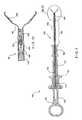
- FIG. 1shows a side elevation view of a through the scope hemostatic clipping device according to an exemplary embodiment of the present invention.
- This deviceis a hand operated tool that is used to insert a hemostatic clip through an endoscope lumen, position the clip over a wound, clamp it and deploy it over the affected tissue.
- the toolis further designed to release the hemostatic clip once it has been clamped in place, and to be withdrawn through the endoscope.
- the hemostatic clipping device 100comprises a handle assembly 102, a shaft section 104, and a clip assembly 106.
- the clip assembly 106is shown more clearly in Fig. 1A .
- the handle assembly 102forms the component that supplies a mechanical actuation force to deploy and clamp the clip.
- the deviceis hand operated (i.e., the user's hands provide the force required to carry out all the functions related to the hemostatic clip).
- the handle assembly 102may include or be coupled to a power source such as a motor or hydraulic pump which may be connected to the distal end of the shaft section 104 by known mechanisms to effect operation of the device.
- the handle assembly 102may be constructed in a manner similar to conventional handle assemblies of the type generally employed in endoscopic biopsy devices or in similar applications.
- the handle assembly 102allows the user to move a control wire 118 or other force transmission member, which extends through the shaft section 104 to the clip assembly 106 at a distal end of the device 100.
- the handle assembly 102comprises a handle body 108 which can be grasped by the user to stabilize the device and apply a force to it.
- a sliding spool 110is connected to control wire 118, so that the user can easily pull or push said wire 106 as desired.
- a sliding spool 110is mounted on the handle body 108 so that it may slide along a slot 116, which maintains its position within the handle assembly 102. Because the sliding spool 110 is connected to the control wire 118, the user may manipulate the control wire 118 by grasping the handle body 108 and moving the sliding spool 110 along the slot 116.
- a return spring 112may be provided within the handle body 108 to bias the sliding spool 110, and thus the control wire 118 toward a desired position. In the present embodiment, the sliding spool 110 is biased to the proximal position.
- the handle assembly 102also includes a connection portion 114, which receives the control wire 118 and attaches the shaft section 104 to the handle assembly 102.
- the shaft section 104mechanically connects the handle assembly 102 to the clip assembly 106 and, together with the clip assembly 106, is designed to be inserted to a target site within a body via a lumen of an endoscope.
- the shaft section 104comprises an outer flexible coil 130 designed to transmit a torque from the proximal end to the distal end of the device 100 and to provide structural strength to the shaft section 104.
- the coil 130may be a conventional coil used in biopsy devices and may, for example, comprise a single, coiled wire.
- the coiled wiremay have a round, square or a rectangular cross section, and is preferably composed of a biocompatible material such as, for example, stainless steel. Additional protective and low friction outer layers may be included on the shaft section 104, according to known methods of construction
- the control wire 118transmits mechanical force applied to the handle 102 to the clip assembly 106.
- the control wire 118has a proximal end attached to a movable part of the handle 102, such as the sliding spool 110, using known methods.
- Stainless steel or other high yield biocompatible materialsmay be used to manufacture the control wire 118, so that the structural integrity of the assembly is maintained. It is also important to prevent stretching of the control wire 118 when under tension since, if the wire stretches, the handle 102 will have to travel a greater distance to carry out a desired operation.
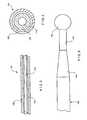
- the distal end of the control wire 118ends in a ball 140 which is used to connect the control wire 118 to the appropriate elements of the clip assembly 106, as will be described below.
- the diameter of the control wire 118is substantially constant from a proximal end thereof to a proximal end of a distal tapered section 144.
- the ball 140preferably has a diameter greater than a diameter of a reduced diameter section 142 coupled to a distal end of the distal tapered section 144 and more preferably has a diameter greater than the proximal portion of the control wire 118, to facilitate attachment to a yoke 204.
- the control wire 118extends the length of the device 100, from the yoke 204 to the sliding spool 110, and is designed to slide longitudinally along the device 100.
- the control wire 118also preferably includes a selected failure zone (e.g., reduced diameter section 142) designed to fail when a predetermined tension is applied thereto through the handle assembly 102.
- the tapered section 144may be used to transition between the main body of the control wire 118 and the reduced diameter section 142, without steps or other discontinuities which may concentrate stress and make the fracture point more unpredictable.
- one purpose of the reduced diameter section 142is to facilitate the release of a hemostatic clip from the hemostatic clipping device 100 once the clip has been properly deployed. It will be apparent to those of skill in the art that the location of the reduced diameter section 142 the along control wire 118 may be varied to take into account specific requirements of the device 100.
- An inner sheath 132may be used in the construction of the shaft section 104, as shown in Figs. 3 and 4 .
- the inner sheath 132provides a low friction bearing surface disposed between the outer diameter of the control wire 118, and the inner diameter of the shaft section 104.
- the inner sheath 132may be formed of a low friction material such as, for example, Teflon TM , HDPE or Polypropylene.
- the inner sheath 132is slidable within the shaft section 104, and the control wire 118 is slidable within the inner sheath 132 forming a low friction system of multiple bearing surfaces.
- a bio-compatible lubricantmay be applied to the inner and outer surfaces of the inner sheath 132, along the length of the shaft section 104.
- silicone lubricantsmay be used for this purpose.
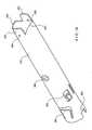
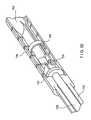
- a slidable over-sheath 150may be included in the design of the shaft section 104, as shown in Figs. 1 and 2 .
- the over-sheath 150is designed to protect the inner lumen of the endoscope from the metal clip assembly 106 and from the metal coil 130 while the hemostatic clipping device 100 passes through the endoscope's lumen. After the clipping device 100 and, more specifically, after the clip assembly 106 has passed through the endoscope, the over-sheath 150 may be withdrawn to expose the distal portion of the clipping device 100.
- the over-sheath 150may be formed, for example, as a single lumen plastic extrusion element slidable over the distal portions of the clipping device 100 to selectively cover and uncover the clip assembly 106.
- the over-sheath 150is formed of a low friction polymer such as, for example, Teflon TM , HDPE, Polypropylene, or similar materials.
- the over-sheath 150may include a grip portion 152 and an elongated body 154.
- the grip portion 152is designed as a handle making it easier for the user to slide the over-sheath 150 over the shaft of the clipping device 100.
- the grip portion 152is made of a rubber-like material to provide a good gripping surface for the user.
- an injection moldable polymersuch as TPE may be used to construct the grip portion 152.
- the elongated body 154may be formed as a substantially cylindrical shell surrounding the shaft of the clipping device 100. The elongated body 154 may be attached to the grip portion 152 using conventional methods as would be understood by those skilled in the art.
- an exemplary grip portion 152comprises a central hollow channel 160 that may be used to receive the shaft of the clipping device 100.
- the central hollow channel 160is aligned with the elongated body 154 to provide a continuous channel containing the shaft of the clipping device 100.
- the material of the grip portion 152preferably has a high coefficient of friction, so that an interference fit is possible between the central hollow channel 160 and the shaft of the clipping device 100 without the use of adhesives or mechanical fastening devices.
- friction bosses 158are provided on an inner diameter of the hollow channel 160 to provide additional friction between the shaft of the clipping device 100 and the over-sheath 150 assembly.
- the friction bosses 158may be formed, for example, as protrusions extending from the inner diameter of the over-sheath 150 and may have a variety of stubby or elongated shapes. The amount of friction between these two components may be balanced so that no unwanted relative movement takes place while, at the same time, making it relatively easy for the user to slide the over-sheath 150 proximally and distally when necessary.
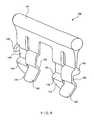
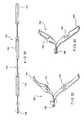
- a sheath stop 156may be provided to prevent the over-sheath 150 from sliding away from the distal end while the clipping device 100 is inserted in the endoscope. As shown in the exemplary embodiment of Figures 2 and 8 , the sheath stop 156 physically blocks the grip portion 152 from sliding proximally to prevent the over-sheath 150 from being withdrawn and exposing the clip assembly 106.
- the sheath stop 156is designed to easily snap into place near the proximal end of the s haft section 104 where it can be reached and manipulated by the operator during the surgical procedure. Once the clip assembly 106 has been inserted through the endoscope to the desired location in the body, the sheath stop 156 may be removed from the shaft section 104 so that the user can move the grip portion 152 proximally to uncover the clip assembly 106.
- the connection between the sheath stop 156 and the shaft section 104may include, for example, pairs of opposing fingers 162, 164 that are designed to snap over the shaft section 104.
- the fingers 162, 164cooperate to securely and releasably hold the body of the shaft section 104 therebetween.
- the fingers 162, 164respectively comprise guide portions 170, 172; shaft channel portions 166, 168; and blocking portions 174, 176. Insertion of the sheath stop 156 on the elongated body 154 is accomplished by pressing the body of the shaft section 104 between the guide portions 170, 172, to spread the fingers 162, 164 and allow further insertion of the shaft 104 between the fingers 162, 164.
- the guide portions 170, 172 and the blocking portions 174, 176are shaped so that insertion of the shaft section 104 towards the channel portions 166, 168 requires less effort than moving the shaft section 104 in the opposite direction.
- the fingers 162, 164snap back to their non-spread position and retain the shaft section 104 in place therebetween.
- the shaft section 104is removed by pulling the sheath stop 156 away from the shaft section 104. Due to the shape of the blocking portions 174, 176, removing the shaft section 104 requires the application of more force than does insertion thereinto. Stops 180 may also be provided on the sheath stop 156 to limit the movement of the shaft section 104 towards the grasping portion 161 to prevent damage to the device that may be caused by excessive spreading of the fingers 162, 164.
- the sheath stop 156is preferably formed of a resilient material, such as a polymer, and may be manufactured, for example, by injection molding.
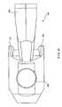
- the clip assembly 106is disposed at the distal end of the clipping device 100, and contains the mechanism that converts the proximal and distal movement of the control wire 118 into the actions necessary to deploy and release a hemostatic clip 90.
- Figures 9, 10 and 11show, respectively, side, top and perspective views of the distal end of the clipping device 100, including the clip assembly 106 having clips in the folded configuration. This configuration is used, for example, to ship the clipping device 100 and to insert the clipping device 100 through the lumen of an endoscope.
- Some of the components of the clip assembly 106include a capsule 200 which provides a structural shell for the clip assembly 106, the clip arms 208 which move between open and closed positions, a bushing 202 attached to the distal end of the control wire 118, and a yoke 204 adapted to connect the capsule 200 to the control wire 118.
- the proximal end of the capsule 200slides over the distal end of the bushing 202.
- a locking arrangement between these two componentsis provided by capsule tabs 212, which lock into the bushing 202 so that mechanical integrity is temporarily maintained between the capsule 200 and the bushing 202.
- Within the capsule 200are a yoke 204 and a tension member 206 which transmit forces applied by the control wire 118 to the clip arms 208.
- the ball 140 formed at the distal end of the control wire 118is mated to a receiving socket 210 formed at the proximal end of the yoke 204.
- a male C-section 214 extending from the tension member 206is received in a corresponding female C-section 216 formed in the yoke 204, so that the two components are releasably connected to one another, as will be described below.
- the clip arms 208 in the closed configurationhave a radius section 300 which is partially contained within the capsule 200 to prevent opening of the arms.
- Each of the clip arms 208goes over the tension member 206 and has a proximal end 222 which slips under a yoke overhang 254, to further control movement of the arms 208.
- Figures 12 and 13show, respectively, top and perspective views of one exemplary embodiment of the clip assembly 106 in an open configuration with the clip arms 208 in a fully open position.
- the open configurationis obtained when the sliding spool 110 shown in Fig. 1 is moved distally so that the ball 140 of the control wire 118 pushes the assembly containing the yoke 204 and the tension member 206 distally, sliding within the capsule 200.
- the distal ends of the clip arms 208are biased toward the open position and revert to this position whenever they are not constrained by the capsule 200.
- a maximum opening of the clip arms 208occurs when the clip arms 208 ride over the folded distal folding tabs 220 which extend from the distal end of the capsule 200, as shown in Figs. 14 and 15 .
- the tabs 220provide a cam surface, and the clip arms 208 act as cam followers, being deflected by the tabs 220.
- the folding tabs 220may also provide a distal stop for the tension member 206, to retain it within the capsule 200.
- the assembly within the capsule 200also moves proximally and the clip arms 208 are withdrawn within the capsule 200.
- clip stop shoulders (CSS) 222contact a distal portion of the capsule 200, for example, the folded tabs 220.
- This interaction of the CSS 222 with the capsule 200provides to the user a first tactile feedback in the form of increased resistance to movement of the sliding spool 110.
- This feedbackgives to the operator a positive indication that further movement of the handle control will cause the hemostatic clip 90 to be deployed from the clip assembly 106. The operator may then decide whether the current position of the clip 90 is acceptable or not.
- the operatorcan deploy the clip 90 by continuing to move the sliding spool 110 with increased proximal pressure to cause the clip arms 208 to close on the tissue. If not, the operator can move the sliding spool 110 distally to re-open the clip arms 208 and extend them out of the capsule 200, reposition the clip 90, and repeat the above steps to close the clip 90 at a more appropriate location.
- the proximal pressure on the sliding spool 110may be increased to continue deployment of the hemostatic clip 90 from the clip assembly 106.
- Figures 16 and 17show respectively a top and side view of the clipping device 100 in this condition.
- the control cable 118pulls the yoke 204 proximally, away from the tension member 206.
- the tension member 206is firmly attached to the clip arms 208 which are prevented from moving proximally by the interaction of the CSS 222 with the folded tabs 220.
- the male C section 214 of the tension member 206yields and loses integrity with the female C section 216 of the yoke 204. This can occur because, in the exemplary embodiment, the tension member 206 is formed of a material with a lower yield strength than the material of the yoke 204.
- the force required to break the tension member 206 away from the yoke 204may be tailored to achieve a desired feedback that can be perceived by the user.
- the minimum force required to break the tension member 206 free of the yoke 204may be selected so that a tactile feedback is felt by the user, to prevent premature deployment of the hemostatic clip 90 while a maximum force may be selected so that other components of the linkage between the sliding spool 110 and the clip arms 208 do not fail before the male C section 214 and the female C section 216 disconnect from one another.
- the tension force necessary to disconnect the two componentsmay be in the range of approximately 4 lbf to about 12 lbf. This range may vary depending on the size of the device and the specific application. To obtain this force at the interface of the male and female C sections 214, 216 a larger force will be applied by the user at the sliding spool 110, since friction within the device may cause losses along the long flexible shaft.
- the clip latches 302are free to engage the latch windows 304 of the capsule 200, thus maintaining the integrity of the capsule-clip arms combination after deployment Details of one exemplary embodiment of the capsule 200 are shown in Figs. 14 , 15 and details of the clip arms 208 are shown in Figs. 18 , 19 and 20 .
- the capsule tabs 306are bent away from the centerline of the capsule 200 by the cam surfaces of the yoke 204. As a result, the capsule tabs 306 are no longer engaged to the corresponding bushing undercuts 350, shown in the side and perspective views of the bushing 202 depicted in Figures 21, 22 . Since the capsule 200 and the bushing 202 (which is securely connected to shaft section 104) are no longer connected, the clip assembly 106 is prevented from being released from the shaft section 104 only by its connection to the ball 140 of the control wire 118.
- a further result of moving the yoke 204 against the distal bushing shoulder 250 of the bushing 202is that the distal end of the wire stop 360 (shown in Figs. 12 , 16 ) is placed near the proximal bushing shoulder 364 (shown in Fig. 22 ).
- the flared fingers 362 located at the distal end of the wire stop 360are compressed as they pass through the central ID of the bushing 202, but return to their normally biased open position (shown in Fig. 23 ) after passing past the proximal bushing shoulder 364. Further distal movement of the sliding spool 110 is thus prevented since that movement would engage the fingers 362 of the wire stop 360 with the proximal bushing shoulder 364.
- This featureprevents the clip assembly 106 from being pushed away from the bushing 202 before the ball 140 is separated from the control wire 118, as will be described below.
- the wire stop 360comprises a tube with a first slotted and flared end attached to the control wire 118 by conventional means. As shown in Fig. 23 , the slots impart flexibility to the device so it can easily pass through the central lumen of the bushing 202. Flared fingers 362 are formed by the slots, and engage the proximal bushing shoulder 364.
- the wire stop 360is made of a material that is biocompatible and that has enough resilience so that the fingers 362 re-open after passage through the bushing 202. For example, stainless steel may be used for this application.
- One feature of the exemplary embodiment of the invention described aboveis that the user receives both tactile and auditory feedback as the clip assembly 106 is deployed and released.
- the separation of the tension member 206 from the yoke 204produces a small clicking noise and a tactile feel that is perceptible while holding the handle assembly 102.
- the change in axial position of the sliding spool 110is thus augmented by the changes in resistance to its movement and by the clicking sound and feel through the start and stop of the movement.
- the useris always aware of the status of the clip assembly 106, and the inadvertent deployment of a hemostatic clip 90 in an incorrect location is less likely. It will be apparent to those of skill in the art that the order of male and female connectors in the device may be reversed or changed without affecting the operation of the device.
- the usermay be certain that the clip assembly 106 has been deployed before the rest of the clipping device 100 is removed from the endoscope. Damage to the tissue being treated could result if the clipping device 100 is removed from the operative site while the hemostatic clip 90 is only partially deployed. Accordingly, clear tactile feedback is preferably incorporated, to augment the auditory and tactile feedback stemming from the separation of the yoke 204 from the tension member 206.
- Figure 24depicts the point at which the clip assembly 106 separates from the rest of the clipping device 100. According to the described embodiment, this second user feedback is obtained by designing the control wire 118 so that it will separate from the end ball 140 only when a predetermined tension is applied to it.
- the ball 140 of the control wire 118is mechanically programmed to yield and separate from the body of the control wire 118 when a tension applied thereto reaches a pre-set level.
- the size of the reduced diameter section 142may be selected so that, when the user continues to move the sliding spool 110 proximally, this reduced diameter section 142 fails as the programmed yield tension is reached to detach the ball 140 from the tapered section 144. The failure of this reduced diameter section 142 provides an additional and clear tactile feedback to the operator indicating that the clip assembly 106 has been completely deployed.
- the sliding spool 110bottoms out at the proximal end of the handle 108, such that a full stroke of the handle assembly 102 is reached.
- the tension required to cause the reduced diameter section 142 to yield and release the ball 140may be selected at any desired point within a wide range of values. However, this force will preferably be greater than the tension force required for the male C section member 214 to separate from the yoke 204. If this condition is not satisfied, a situation may occur where the clip assembly 106 is locked in place on the patient's tissue, but cannot be released from the clipping device 100. It will be apparent that this situation should be avoided.
- the tension force required to separate the ball 140 from the body of the control wire 118is in the range of between about 10 lbf and 20 lbf at the distal end of the control wire 118.
- losses along the elongated flexible shaftmay require the user to apply a force substantially greater than this to the handle body 102.
- the usermay pull the rest of the clipping device 100 from the endoscope.
- the yoke 204is retained within the capsule 200 by the spring and frictional forces of various features of the capsule 200, such as the capsule tabs 306.
- the over-sheath 150may be moved distally by the user over the entire remaining portions of the shaft section 104 to prevent damage to the endoscope as the clipping device 100 is withdrawn therethrough.
- the sheath stop 156may also be placed on the shaft section 104 proximally of the over-sheath grip 152 to prevent inadvertent sliding of the over-sheath 150 from the distal end of the device 100.
- the clip arms 208are shown in detail in Figures 18 , 19 and 20 ; the tension member 206 is shown in side and top views in Figures 25, 26 ; while top and side views of the yoke 204 are shown respectively in Figures 27 and 28 .
- the clip arms 208are preferably formed of a biocompatible material such as Nitinol, Titanium or stainless steel. Maximum spring properties may be obtained by using materials such as 400 series stainless or 17-7 PH.
- a tear drop keyway 400is formed in the clip arm 208 to mate with a corresponding tear drop key 402 formed on the tension member 206. This feature maintains the relative positions of these two components and of the yoke 204 substantially constant.
- the shape of the keyways 400may be varied.
- the keyway 400may be oval or elliptical.
- Central portions of the clip arms 208define a spring section 404.
- the clip arms 208are allowed to pivot over the tension member 206, which in turn biases the distal ends 252 towards the open configuration so that, when the distal ends of the clip arms 208 are moved distally beyond the distal end of the capsule 200, they move to the open position.
- the proximal ends 252 of the clip arms 208spring outward to engage the corresponding latch windows 304 in the capsule 200.
- the clip arms 208also comprise a radius section 300 that adds strength to the clip assembly 106 and reduces system friction.
- the radius of the radius section 300preferably approximately matches an inner diameter of the capsule 200 and has a smooth profile to avoid scratching the inner surface of the capsule 200.
- a pre-load angle ⁇is defined between the radius section 300 and the spring section 404.
- the pre-load angle ⁇determines how much interference (pre-load) exists between the two opposing clip arms 208 at their distal ends when closed. The greater the pre-load angle ⁇ , the greater the engaging force that is applied by the clip arms 208. However, this condition also causes the greatest system friction when the hemostatic clip 90 is closed.
- the clip arms 208also comprise interlocking teeth 408 disposed at their distal ends.
- the teeth 408are identical so that the arms may be interchangeable and will mesh smoothly with the set facing them.
- the teeth 408are disposed at a nose angle ⁇ which is preferably between approximately 90 and 135 degrees, but in other applications may be greater or lesser than the described range.
- One exemplary embodiment of the capsule 200is shown in detail in Figures 14 and 15 and comprises alignment keyways 500 designed to mate with corresponding features on the bushing 202 to rotationally align the two components.
- the capsule tabs 306may be bent towards the centerline of the capsule 200 to engage the bushing undercuts 350. The engagement maintains the integrity of the connection between the capsule assembly 200 and the rest of the clipping device 100 until the yoke is pulled into the distal bushing shoulder.
- the capsule overhangs 502provide added clamping strength to the deployed clip arms 208. This is achieved by reducing the length of the portion of each clip arm 208 not supported by a portion of the capsule 200. This feature does not affect the amount of tissue that may be captured by the clip arms 208 since the capsule overhangs 502 extend on a plane substantially parallel to the plane of the clip arms 208.
- Additional features of the capsule 200include an assembly aid port which may be used to assist in aligning the components of the clip assembly 106.
- Bending aids 506facilitate a smooth bend when the distal folding tabs 220 are bent inward, as described above.
- the bending aids 506, as shown,are holes aligned with the folding line of the tabs 220, but may also include a crease, a linear indentation, or other type of stress concentrator.
- the capsule 200may be formed from any of a variety of biocompatible materials. For example, stainless steel, Titanium or Nitinol or any combination thereof may be used. High strength polymers like PEEK TM or Ultem TM may also be used to form the capsule 200, with a heat set treatment being used to adjust positionable elements.
- Figures 25 and 26depict additional details of the tension member 206.
- tear drop keys 402are designed to engage the tear drop keyways 400 of the clip arms 208, as described above.
- Clip follower planes 508are shaped to form a fulcrum which allows the clip arms 208 to rock between the open and closed configurations.
- the tension member 206comprises a distal stop face 510 which abuts the distal folding tabs 220 of the capsule 200 to stop the distal motion of the capsule assembly 106.
- all surfaces and edges of the tension member 206 that are in contact with the inner surfaces of the capsule 200preferably have a radius substantially similar to an inner radius of the capsule 200 to provide a sliding fit therein.
- the tension member 206is preferably formed of a biocompatible polymer, monomer or thermoset.
- the type of mechanism selected to release the tension member 206 from the yoke 204may determine the type of material used since a release due to fracture of the male C section 214 requires a relatively brittle material while release due to yielding without fracture calls for a softer material.
- Figs. 27-29Additional details of the yoke 204 are shown in Figs. 27-29 .
- the ball cavity 602has a diameter sufficiently large to allow the ball 140 to pass therethrough while the wire cavity 604 is large enough to allow the control wire 118 to pass therethrough, but not large enough to allow the ball 140 pass therethrough.
- the proximal end of wire 140is inserted into the ball cavity 602 until the ball bottoms out, and then the control wire 118 is rotated until it is seated in the control wire cavity 604. This constrains further movement of the ball 140.
- the yoke 204is preferably made of a biocompatible metal such as stainless steel or a high strength polymer such as Ultem TM .
- the clipping device 100may be scaled to fit the requirements of different surgical procedures.
- the clipping device 100is sized to fit through an endoscope having a working channel diameter of approximately 0.110 inches.
- the exemplary bushinghas a length of about 0.22 inches and an OD of approximately 0.085 inches.
- the exemplary capsule 200has a length of about 0.5 inches, an OD of about 0.085 inches, and a wall thickness of about 0.003 inches.
- the rigid length of the exemplary capsule 200 and the bushing 202is approximately 0.625 inches. It is important to maintain this length short enough so that the assembly will not have difficulty passing through bends of the flexible endoscope.
- the outer sheathhas an ID of approximately 0.088 inches and an OD of about 0.102 inches.
- the overall length of the exemplary clipping deviceis approximately 160 inches, while the tissue grasping portion of the clip arms 208 is approximately 0.4 inches long.
- a multiclip endoscopic hemostatic devicemay be used to discharge multiple hemostatic clips without removing the device from the endoscope.
- This multiclip deviceachieves equal or better results than conventional single deployment clipping devices, while greatly facilitating the placement of multiple hemostatic clips.
- the clips used by the multiclip device according to the present inventionare substantially similar in size to conventional hemostatic clips, and thus can be used with conventional endoscopes. According to the invention, the cost of manufacturing the multiclip apparatus is sufficiently low to permit the units to be disposable after use on a single patient.
- the multiclip hemostatic clipping apparatusis used in a minimally invasive environment, such that it is applied to the surgical site through an endoscope.
- the distal end of the hemostatic multiclip deviceis inserted through the working lumen of the endoscope, and is brought in the vicinity of the surgical site where the bleeding occurs.
- an endoscope having a working channel of about 1.8 mm inner diameter or greatermay be used to reach the surgical site.
- the proximal ends of the endoscope and of the hemostatic multiclip deviceare provided with hand controls used by the user/physician to operate the devices.
- the hemostatic multiclip deviceuses a magazine containing a plurality of hemostatic clips that is advanced through the endoscope's working lumen, to a location near the surgical site.
- the magazinemay be attached to a sheath which protects the inner surfaces of the endoscope from damage caused by, for example, contact with sharp edges of the magazine and clip assembly, and which extends beyond the magazine through the length of the endoscope.
- the hemostatic clipsare joined in a clip chain which is inserted in the magazine and is free to translate in the magazine within certain limits as will be described below.
- Each of the clipsmay be formed, for example, of sheet metal or of another material having appropriate mechanical and bio-compatibility properties. The material of the clips is selected to resist plastic deformation while constrained in the closed configuration, so that the hemostatic clips will return to the open configuration when not otherwise restrained.
- a modified version of the clipping device 100may be used with the clip magazine and clip chain described above.
- a clip magazine containing multiple hemostatic clipsmay be inserted into the proximal end of the shaft section 104, such that the clips are deployed from the distal end thereof.
- a handle 108 and sliding spool 110, or similar implements,may be used in conjunction with a control linkage to operate the multiclip dispensing apparatus, as will be described in detail below.
- Fig. 31shows an exemplary embodiment of a hemostatic clip according to the present invention.
- An exemplary clip 702comprises two clip arms 704 which have inner surfaces facing one another for grasping and retaining tissue therebetween when placed in a closed configuration.
- Fig. 31shows the clip arms 704 in an open configuration assumed by the clip 702 in an early phase of deployment, before the tissue is clamped thereby.
- the clip 702may be formed of two parts joined at a common portion 705, or may be of a single piece construction.
- the clip 702is biased toward the open configuration as shown in Fig. 31 .
- a sliding lock ring 706is used to lock the clip arms 704 in the closed configuration assumed by the clip 702 as it is clamped on tissue.
- the sliding locking ring 706may be replaced by different devices adapted to lock the clip arms 704 in the closed configuration.
- a plurality of protrusions with catches 710may be formed on each of the clip arms 704' of the clip 703 to retain the device in the closed configuration once the clip 703 has been clamped in place on tissue.
- Fig. 34shows another exemplary embodiment of a locking mechanism for the hemostatic clip 705 in which a single snap 712 extends from each of the clip arms 704" to lock with a corresponding snap 712 extending from an opposing clip arm 704".
- the specific mechanism used to lock the clip arms 704 in the closed configurationmay be selected depending, for example, on the desired size of the device and on the strength of the desired clamping force.
- a distal portion of the magazine containing the clip chainmay be shaped to close the clip arms 704', 704" so that the snaps 710, 712 lock in the closed configuration.
- a plurality of clipsmay be loaded in the magazine for use with the hemostatic multiclip device according to the present invention.
- Fig. 32shows an exemplary embodiment of a clip chain 700 according to the invention.
- the clip chain 700is formed by joining hemostatic clips 702 to one another head to tail using, for example, a linking feature 708.
- the linking feature 708comprises an attachment which binds two adjacent clips 702 to one another for so long as there is no movement of the joined clip ends in a direction perpendicular to a longitudinal axis of the clips. In this manner, the clip chain 700 remains intact as long as the clips are translated in a direction generally along the longitudinal axis of the clips.
- a clip 702is released from the adjacent clip 702 by moving the joined ends of the clips 702 relative to one another in a direction perpendicular to the longitudinal axis of the clip chain 700.
- the linking feature lining feature 708is clamped between distal ends of clip arms 704 which are held in the closed configuration.
- the linking feature 708may be formed integrally with the body of hemostatic clip 702, or may be an optional addition that may be attached to more conventional clips.
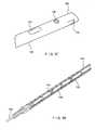
- FIG. 36An exemplary clip magazine 720 is shown in perspective view in Fig. 36 .
- the clip chain 700(shown in perspective view in Fig. 35 ) is inserted longitudinally into a hollow channel 722 of the magazine 720, as shown in Fig. 38 .
- the magazine 720according to this embodiment is a generally cylindrical structure located at the distal end of the hemostatic multiclip device, which contains a portion or all of the clips 702 within the clip chain 700.
- the magazine 720, together with the clip chain 700forms a capsule having dimensions and sufficient flexibility to comply with the curvature of the endoscope's working channel.
- Optional compliance features 723are included to impart flexibility to the body of the magazine 720 and may, for example, comprise a plurality of partially circumferential slits formed in the magazine 720.
- the most proximal of the clips 702is releasably connected to a control link 726.
- the control link 726carries compression and tension loads, so that clip chain 700 may be translated in both directions through forces transmitted via the control link 726.
- the control link 726according to the exemplary embodiment of the invention may be formed, for example, as a rigid tube, a semi rigid wire, or by any other structural element capable of transmitting tension and compression loads along the length of the hemostatic multiclip device.
- the control link 726is connected to a control handle at the proximal end, to give to the surgeon control of the deployment of the clips 702.
- Figure 30shows a detail of the connection between the control link 726 and the most proximal hemostatic clip 702.
- the control link 726is formed as a rod or tube which terminates in a connector portion 727 adapted to push against the lining feature 708.
- a connector portion 727may also be designed to apply a tension force to the lining feature 708, in a known manner.
- An optional sheath 725is used to encapsulate the control link 726, to protect the working channel of the endoscope from damage and to reduce friction between the moving control link 726 and the clip magazine 720.
- a control handle portion of the hemostatic multiclip device(not shown) is provided at the proximal end of the device, extending outside of the proximal end of the endoscope to form a clip deployment control element.
- the control portionmay be similar to that shown in Fig. 1 comprising hand controls which operate the control link 726 to cause the deployment and release of successive clips 702.
- hand movements of the surgeonmay be transformed within the control portion into longitudinal movements of the control link 726 along the working channel of the endoscope.
- the clip chain 700is rigid in compression and supports tensile loads, at least while contained with in the clip magazine 720. The clip chain 700 can therefore be translated along the magazine 720 via movement of the control link 726.
- the clip chain 700is formed of a plurality of hemostatic clips 702 which remain attached to one another while they are within the cylindrical containment of the clip magazine 720 which supports and constrains the clips 702 of the clip chain 700 in the radial direction through a large portion of its length. This prevents pairs of adjacent clips 702 from disconnecting from one another by preventing relative radial movement between the clips 702. In particular, the radial movement of the substantially closed clip arms 704 of a first hemostatic clip is prevented, so that the linking feature 708 of a second clip, adjacent to the first clip, is not released.
- the exemplary clip chain 700minimizes the width of the device, as the clip chain 700 is no wider than the clips 702 themselves.
- the diameter of the clip chain 700works in conjunction with the shape of the distal end 724 of the clip magazine 720 to control the position of the distal portion of the clip chain 700 therethrough.
- the magazine 720has a reduced cross-section portion 730 limiting the diameter of items passing therethrough.
- the reduced cross-section portion 730is sized to allow passage therethrough of only a single clip 702 unattached to another clip at its distal end.
- the diameter of two connected clips 702is slightly greater than the diameter of a single, unattached clip 702 as the clip arms 704 are not fully closed when they are locked onto the linking feature 708 of another clip 702.
- an inner diameter of the reduced cross-section portion 730is selected to be slightly greater than the outer diameter of a single, unattached clip 702 and slightly less than the outer diameter of a clip 702 which is attached to an adjacent clip 702.
- the function of the clip chain 700is better shown in Figs. 39, 40 , where a clip 702' is placed to lead the clip chain 700 through the distal end 724 and through the reduced cross-section portion 730.
- the clip chain 700is pushed distally until further distal movement of a next most distal clip 702 coupled to the proximal end of the most distal clip 702 is stopped by the reduced cross-section portion 730.
- the most distal clip 702'extends out of the magazine 720 with the clip arms 704 moved to the open position by their bias.
- a camming mechanismmay be employed to ensure that the clip arms 704 move to the open configuration when the clip 702 is pushed distally from the magazine 720.
- Fig. 39shows a configuration wherein the most distal hemostatic clip 702' has been pushed distally out of the clip magazine 720, past the distal end 724 thereof.
- the clip arms 704 of the next most distal clip 702 of the chain 700abut the reduced cross-section portion 730 ( Fig. 40 ).
- the control link 726is pulled proximally in a proximal stroke, so that the clip chain 700 (including the most distal clip 702') is pulled proximally into the magazine 720, as shown in Fig. 41 .
- the clip sliding lock ring 706is held distally by lock ring anti-pull back tabs 734 as the most distal clip 702' is pulled proximally. This causes the lock ring 706 to move partially over the clip arms 704' locking them in the closed configuration and firmly grasping therewithin. At this point the most distal clip 702' is clamped securely over the tissue, but is still attached to the clip chain 700 via the linking feature 708.
- the pull back distance of the most distal clip 702'may be controlled, for example by selecting a position of the additional feature 733 so that the link between the most distal clip 702' and the next most distal clip 702 is located in a relief portion 732 of the distal end 724.
- the relief portion 732includes a movable tab or opening which allows local diametrical expansion of a clip 702 within that portion of the magazine 720.
- the clip arms 704 of the next most distal clip 702are pushed diametrically outward over the linking feature 708 of the most distal hemostatic clip 702', which now acts as a cam surface.
- the relief portion 732 of the clip magazine 720allows outward expansion of the clip arms 704 over the linking feature 708 to permit the clip arms 704 to continue moving proximally and separate from the most distal clip 702'.
- the distal most clip 702'is still prevented from moving further proximally by the additional feature 733 described above, but is now free to move distally and exit the magazine 720.
- the most distal clip 702'after release from clip chain 700, exits the clip magazine 720 due to the tension applied to it by the tissue clamped thereby.
- the clip 702'may be pushed out of the magazine 720 by distal movement of the clip chain 700 as the next most distal clip 702 is pushed toward the distal end 724.
- Fig. 42depicts a configuration in which the "former" most distal clip 702' has been ejected from the clip magazine 720, and is clamped securely to the target tissue.
- a "new" most distal clip 702is now positioned partially out of the magazine 720 with its clip arms 704 in the open configuration.
- the "new" most distal clip 702is still connected to the clip 702 immediately proximal to it which is positioned fully inside of the clip magazine 720 and which forms part of the clip chain 700.
- the usermay position the open clip arms 704 over a new portion of desired tissue and repeat the process described above to clamp the clip arms 704 over the tissue, lock them closed, and release the new distal-most clip 702 from the clip chain 700 and eject the clip 702 from the clip magazine 720.
Landscapes
- Health & Medical Sciences (AREA)
- Surgery (AREA)
- Life Sciences & Earth Sciences (AREA)
- Heart & Thoracic Surgery (AREA)
- Nuclear Medicine, Radiotherapy & Molecular Imaging (AREA)
- Vascular Medicine (AREA)
- Engineering & Computer Science (AREA)
- Biomedical Technology (AREA)
- Reproductive Health (AREA)
- Medical Informatics (AREA)
- Molecular Biology (AREA)
- Animal Behavior & Ethology (AREA)
- General Health & Medical Sciences (AREA)
- Public Health (AREA)
- Veterinary Medicine (AREA)
- Surgical Instruments (AREA)
Abstract
Description
- Endoscopic procedures to treat pathologies of the gastro-intestinal ("Gl") system, the biliary tree, the vascular system and other body lumens are becoming increasingly common. The endoscope, which is basically a hollow tube placed at a desired location within the body to facilitate access to body ducts and lumens, etc. is unable to carry out many procedures on its own. Additional devices are often inserted to the target site through lumens or working channels of the endoscope to perform the desired treatment via controls which remain outside the body.
- A hemostatic clipping tool is one of the devices which may be inserted through an endoscope to deploy a clip to stop internal bleeding by clamping together the edges of a wound. A clipping tool complete with a clip attached to its distal end is inserted through the endoscope to the location of the wound and the clip is then remotely manipulated into position over the site of the bleeding, clamped over the wound and detached from the tool. After a number of clips sufficient to stop the bleeding has been deployed, the tool is withdrawn through the endoscope. The size and shape of the clips and clipping tool are limited by the inner diameter of the lumen(s) of the endoscope placing constraints on the design of clip positioning and release mechanisms which may be employed.
- At times it may be difficult to properly position hemostatic clips over a wound. When clips are Improperly deployed, additional clips may be required to stop the bleeding, extending the time required for and the complexity of the procedure while leaving additional medical devices within the patient. It is also important that the device operator be certain of the status of the clip during the deployment operation. For example, before withdrawing the tool from the endoscope, the operator should have a positive indication that a clip has fully deployed and has been released from the tool. At the same time the design of the tool should ensure that clips are fully released after they have been closed over the tissue.
- Document
US 5,366,459 A discloses a surgical clip and clip application apparatus comprising a plurality of clips, a control member, and a magazine containing the clip chain made of the plurality of clips. The apparatus comprises an applicator including an elongated sheath consisting of the tubular members. These three elongated members are slidably attached to each other, where the relation between the different tubular members is biased by the handle, the curved spring member, and the finger grip. Within the tubular members, the chain of clips is disposed. The most proximal clip is coupled to a control member defined by a pusher member and a spring member, which biases the chain of clips to be pushed distally. Similar apparatuses are shown in documentsUS 4 512 345 A andUS 4 557 263 . - In one aspect, the present invention is directed to an apparatus for applying clips to tissue, comprising a plurality of clips, each of the clips including a proximal end having a pair of opposed jaws and a distal end including a linking feature, where the clips are linked to one another to form a clip chain with a linking feature of a distal-most one of the clips being gripped between the jaws of an immediately proximal one of the clips and a control linkage coupled to a proximal-most one of the clips for applying tension and compression to the clip chain in combination with a magazine containing the clip chain, the magazine including an abutment surface sized to prevent passage distally therebeyond of a clip having received between its jaws a linking feature of an immediately distal clip and an opening location within which the jaws of a clip are permitted to open to release a linking feature therefrom.
- Further, a method of deploying hemostatic clips is described, comprising inserting to a target site in a body a magazine including a plurality of hemostatic clips connected in a clip chain, translating the clip chain distally to extend a distal-most one of the clips out of a distal end of the magazine to open clip arms of the distal-most clip into a tissue receiving configuration and positioning the distal-most clip to receive a first target portion of tissue between the clip arms thereof in combination with translating the clip chain proximally to draw the distal-most clip back into the magazine and close the clip arms of the distal-most clip over the first target portion of tissue and translating the clip chain further proximally to detach the distal-most clip from a next most distal clip of the clip chain. Then, the magazine is moved to a second target location to deploy the next most distal clip over a second target portion of tissue.
Figure 1 is a schematic side view of a clipping device according to an embodiment of the present invention, with a detail view of an exemplary clip assembly;Figure 2 is a schematic side view of the embodiment shown inFig. 1 , with a outer sheath;Figure 3 is a cut away side view of the shaft section according to an embodiment of the present invention;Figure 4 is a cross sectional view of the shaft section shown inFig. 3 ;Figure 5 is a detail view of the distal end of the control wire according to an embodiment of the present invention;Figure 6 is a perspective view of an outer sheath according to an embodiment of the present invention;Figure 7 is an cross sectional exploded view of the handle of the outer sheath shown inFigure 6 ;Figure 8 is a perspective view of an outer sheath lock accord ing to an embodiment of the present invention;Figure 9 is a cross sectional side view of a distal end of a clipping device according to an embodiment of the present invention;Figure 10 is a cross sectional top view of a distal end of the clipping device shown inFig 9 ;Figure 11 is a perspective view of the distal end of the clipping device shown inFig. 9 ;Figure 12 is a top view of the clip arms according to an embodiment of the present invention;Figure 13 is a perspective view of the clip arms shown inFig. 12 , according to an embodiment of the present invention;Figure 14 is a perspective view of a capsule according to an embodiment of the present invention;Figure 15 is a cross sectional side view of the of the capsule shown inFig. 14 ;Figure 16 is a top view of the distal end of a clipping device according to an embodiment of the present invention;Figure 17 is a side view of the distal end shown inFig. 16 ;Figure 18 is a perspective view of a clip arm according to an embodiment of the present invention;Figure 19 is a side view of the clip arm shown inFig. 18 ;Figure 20 is a top view of the clip arm shown inFig. 18 ;Figure 21 is a perspective view of a bushing according to an embodiment of the present invention;Figure 22 is a cross sectional side view of the bushing shown inFig. 21 ;Figure 23 is a perspective view of a wire stop according to an embodiment of the present invention;Figure 24 is a schematic side view of a clip assembly detached from a bushing, according to an embodiment of the present invention;Figure 25 is a side view of a tension member according to an embodiment of the present invention;Figure 26 is a top view of the tension member shown inFig. 25 ;Figure 27 is a top view of a yoke according to an embodiment of the present invention;Figure 28 is a perspective view of the yoke shown inFig. 27 ;Figure 29 is a top view of a yoke with a control wire according to an embodiment of the present invention;Figure 30 shows a detail of a connection between a control link and a clip chain according to an embodiment of the invention;Figure 31 shows a perspective view of an individual hemostatic clip of a clip chain according to an embodiment of the invention;Figure 32 shows a side elevation view of a clip chain according to an embodiment of the invention;Figure 33 shows a perspective view of a second embodiment of a clip for a clip chain according to the invention;Figure 34 shows a perspective view of a third embodiment of a clip for a clip chain according to the invention;Figure 35 shows a perspective view of the clip chain shown inFig. 32 ;Figure 36 shows a perspective view of a clip magazine according to an embodiment of the invention;Figure 37 shows a distal end detail of the clip magazine shown inFig. 36 ;Figure 38 shows a cut away perspective view of a clip chain loaded in a clip magazine according to an embodiment of the invention;Figure 39 shows the clip chain ofFig. 38 being pushed out of the clip magazine;Figure 40 shows the clip chain ofFig 38 yet further out of the clip magazine with one clip deployed;Figure 41 shows a distal end detail of the clip magazine shown inFig. 39 ; andFigure 42 shows the clip chain ofFig. 38 with a clip deployed and released from the clip chain.- Hemostatic clips are routinely used to stop internal bleeding. In the simplest form, these clips grasp tissue surrounding a bleeding opening and bring the edges together to allow the natural scarring process to close the opening. Specialized endoscopic hemostatic clipping devices are used to bring clips to desired locations within the body and to position and deploy clips at appropriate places on the tissue. The clipping device is then withdrawn, leaving the clip(s) within the patient. One such hemostatic clipping devices is described in
U.S. Patent Application Serial No. 10/647,512, filed on September 30, 2003 - As described above, endoscopic hemostatic clipping devices are designed to reach affected tissues deep within a patient's body, such as within the Gl tract, the pulmonary system, the vascular system or within other lumens and ducts. During the procedures to treat those areas, an endoscope is generally used to provide access to and visualization of the tissue which is to be treated. The clipping device may, for example, be introduced through a working lumen of the endoscope. The design and construction of such a "through the scope" endoscopic hemostatic clipping device presents several challenges. The endoscopic clipping device has to be sufficiently small to fit in the lumen of an endoscope and, at the same time, must be designed to provide for the positive placement and actuation of the hemostatic clip. Feedback to the operator is preferably also provided so that the operator will not be confused as to whether the hemostatic clip has been properly locked in place on the tissue and released from the device before the device itself is withdrawn through the endoscope.
Figure 1 shows a side elevation view of a through the scope hemostatic clipping device according to an exemplary embodiment of the present invention. This device is a hand operated tool that is used to insert a hemostatic clip through an endoscope lumen, position the clip over a wound, clamp it and deploy it over the affected tissue. The tool is further designed to release the hemostatic clip once it has been clamped in place, and to be withdrawn through the endoscope. To more clearly explain the operation and construction of the exemplary device, it may be divided into three principal components. As shown, thehemostatic clipping device 100 comprises ahandle assembly 102, ashaft section 104, and aclip assembly 106. Theclip assembly 106 is shown more clearly inFig. 1A .- The
handle assembly 102 forms the component that supplies a mechanical actuation force to deploy and clamp the clip. In this embodiment, the device is hand operated (i.e., the user's hands provide the force required to carry out all the functions related to the hemostatic clip). However, those skilled in the art will understand that thehandle assembly 102 may include or be coupled to a power source such as a motor or hydraulic pump which may be connected to the distal end of theshaft section 104 by known mechanisms to effect operation of the device. Thehandle assembly 102 may be constructed in a manner similar to conventional handle assemblies of the type generally employed in endoscopic biopsy devices or in similar applications. Thehandle assembly 102 allows the user to move acontrol wire 118 or other force transmission member, which extends through theshaft section 104 to theclip assembly 106 at a distal end of thedevice 100. Thehandle assembly 102 comprises ahandle body 108 which can be grasped by the user to stabilize the device and apply a force to it. A slidingspool 110 is connected to controlwire 118, so that the user can easily pull or push saidwire 106 as desired. - As shown in
Figures 1 and2 , a slidingspool 110 is mounted on thehandle body 108 so that it may slide along aslot 116, which maintains its position within thehandle assembly 102. Because the slidingspool 110 is connected to thecontrol wire 118, the user may manipulate thecontrol wire 118 by grasping thehandle body 108 and moving the slidingspool 110 along theslot 116. Areturn spring 112 may be provided within thehandle body 108 to bias the slidingspool 110, and thus thecontrol wire 118 toward a desired position. In the present embodiment, the slidingspool 110 is biased to the proximal position. Thehandle assembly 102 also includes aconnection portion 114, which receives thecontrol wire 118 and attaches theshaft section 104 to thehandle assembly 102. - The
shaft section 104 mechanically connects thehandle assembly 102 to theclip assembly 106 and, together with theclip assembly 106, is designed to be inserted to a target site within a body via a lumen of an endoscope. As shown inFigures 3 and 4 , theshaft section 104 comprises an outerflexible coil 130 designed to transmit a torque from the proximal end to the distal end of thedevice 100 and to provide structural strength to theshaft section 104. Thecoil 130 may be a conventional coil used in biopsy devices and may, for example, comprise a single, coiled wire. The coiled wire may have a round, square or a rectangular cross section, and is preferably composed of a biocompatible material such as, for example, stainless steel. Additional protective and low friction outer layers may be included on theshaft section 104, according to known methods of construction - The
control wire 118 transmits mechanical force applied to thehandle 102 to theclip assembly 106. Thecontrol wire 118 has a proximal end attached to a movable part of thehandle 102, such as the slidingspool 110, using known methods. Stainless steel or other high yield biocompatible materials may be used to manufacture thecontrol wire 118, so that the structural integrity of the assembly is maintained. It is also important to prevent stretching of thecontrol wire 118 when under tension since, if the wire stretches, thehandle 102 will have to travel a greater distance to carry out a desired operation. As shown inFigure 5 , the distal end of thecontrol wire 118 ends in aball 140 which is used to connect thecontrol wire 118 to the appropriate elements of theclip assembly 106, as will be described below. In this embodiment, the diameter of thecontrol wire 118 is substantially constant from a proximal end thereof to a proximal end of a distaltapered section 144. Theball 140 preferably has a diameter greater than a diameter of a reduceddiameter section 142 coupled to a distal end of the distaltapered section 144 and more preferably has a diameter greater than the proximal portion of thecontrol wire 118, to facilitate attachment to ayoke 204. Thecontrol wire 118 extends the length of thedevice 100, from theyoke 204 to the slidingspool 110, and is designed to slide longitudinally along thedevice 100. - The
control wire 118 also preferably includes a selected failure zone (e.g., reduced diameter section 142) designed to fail when a predetermined tension is applied thereto through thehandle assembly 102. The taperedsection 144 may be used to transition between the main body of thecontrol wire 118 and the reduceddiameter section 142, without steps or other discontinuities which may concentrate stress and make the fracture point more unpredictable. As will be described in greater detail below, one purpose of the reduceddiameter section 142 is to facilitate the release of a hemostatic clip from thehemostatic clipping device 100 once the clip has been properly deployed. It will be apparent to those of skill in the art that the location of the reduceddiameter section 142 the alongcontrol wire 118 may be varied to take into account specific requirements of thedevice 100. - An
inner sheath 132 may be used in the construction of theshaft section 104, as shown inFigs. 3 and 4 . Theinner sheath 132 provides a low friction bearing surface disposed between the outer diameter of thecontrol wire 118, and the inner diameter of theshaft section 104. Theinner sheath 132 may be formed of a low friction material such as, for example, Teflon™, HDPE or Polypropylene. In one exemplary embodiment, theinner sheath 132 is slidable within theshaft section 104, and thecontrol wire 118 is slidable within theinner sheath 132 forming a low friction system of multiple bearing surfaces. To further reduce friction, a bio-compatible lubricant may be applied to the inner and outer surfaces of theinner sheath 132, along the length of theshaft section 104. For example, silicone lubricants may be used for this purpose. - A slidable over-sheath 150 may be included in the design of the
shaft section 104, as shown inFigs. 1 and2 . The over-sheath 150 is designed to protect the inner lumen of the endoscope from themetal clip assembly 106 and from themetal coil 130 while thehemostatic clipping device 100 passes through the endoscope's lumen. After theclipping device 100 and, more specifically, after theclip assembly 106 has passed through the endoscope, the over-sheath 150 may be withdrawn to expose the distal portion of theclipping device 100. The over-sheath 150 may be formed, for example, as a single lumen plastic extrusion element slidable over the distal portions of theclipping device 100 to selectively cover and uncover theclip assembly 106. In one embodiment, the over-sheath 150 is formed of a low friction polymer such as, for example, Teflon™, HDPE, Polypropylene, or similar materials. - The over-sheath 150 may include a
grip portion 152 and anelongated body 154. Thegrip portion 152 is designed as a handle making it easier for the user to slide the over-sheath 150 over the shaft of theclipping device 100. In one exemplary embodiment, thegrip portion 152 is made of a rubber-like material to provide a good gripping surface for the user. For example, an injection moldable polymer such as TPE may be used to construct thegrip portion 152. Theelongated body 154 may be formed as a substantially cylindrical shell surrounding the shaft of theclipping device 100. Theelongated body 154 may be attached to thegrip portion 152 using conventional methods as would be understood by those skilled in the art. - As shown in
Figures 6 and 7 , anexemplary grip portion 152 comprises a centralhollow channel 160 that may be used to receive the shaft of theclipping device 100. The centralhollow channel 160 is aligned with theelongated body 154 to provide a continuous channel containing the shaft of theclipping device 100. The material of thegrip portion 152 preferably has a high coefficient of friction, so that an interference fit is possible between the centralhollow channel 160 and the shaft of theclipping device 100 without the use of adhesives or mechanical fastening devices. In one embodiment,friction bosses 158 are provided on an inner diameter of thehollow channel 160 to provide additional friction between the shaft of theclipping device 100 and the over-sheath 150 assembly. Thefriction bosses 158 may be formed, for example, as protrusions extending from the inner diameter of the over-sheath 150 and may have a variety of stubby or elongated shapes. The amount of friction between these two components may be balanced so that no unwanted relative movement takes place while, at the same time, making it relatively easy for the user to slide the over-sheath 150 proximally and distally when necessary. - A
sheath stop 156 may be provided to prevent the over-sheath 150 from sliding away from the distal end while theclipping device 100 is inserted in the endoscope. As shown in the exemplary embodiment ofFigures 2 and8 , the sheath stop 156 physically blocks thegrip portion 152 from sliding proximally to prevent the over-sheath 150 from being withdrawn and exposing theclip assembly 106. Thesheath stop 156 is designed to easily snap into place near the proximal end of thes haft section 104 where it can be reached and manipulated by the operator during the surgical procedure. Once theclip assembly 106 has been inserted through the endoscope to the desired location in the body, thesheath stop 156 may be removed from theshaft section 104 so that the user can move thegrip portion 152 proximally to uncover theclip assembly 106. - The connection between the
sheath stop 156 and theshaft section 104 may include, for example, pairs of opposingfingers shaft section 104. Thefingers shaft section 104 therebetween. Thefingers guide portions shaft channel portions portions elongated body 154 is accomplished by pressing the body of theshaft section 104 between theguide portions fingers shaft 104 between thefingers guide portions portions shaft section 104 towards thechannel portions shaft section 104 in the opposite direction. - Once
shaft section 104 has been placed within thechannel portions fingers shaft section 104 in place therebetween. Theshaft section 104 is removed by pulling thesheath stop 156 away from theshaft section 104. Due to the shape of the blockingportions shaft section 104 requires the application of more force than does insertion thereinto.Stops 180 may also be provided on the sheath stop 156 to limit the movement of theshaft section 104 towards the graspingportion 161 to prevent damage to the device that may be caused by excessive spreading of thefingers sheath stop 156 is preferably formed of a resilient material, such as a polymer, and may be manufactured, for example, by injection molding. - The
clip assembly 106 is disposed at the distal end of theclipping device 100, and contains the mechanism that converts the proximal and distal movement of thecontrol wire 118 into the actions necessary to deploy and release ahemostatic clip 90.Figures 9, 10 and11 show, respectively, side, top and perspective views of the distal end of theclipping device 100, including theclip assembly 106 having clips in the folded configuration. This configuration is used, for example, to ship theclipping device 100 and to insert theclipping device 100 through the lumen of an endoscope. Some of the components of theclip assembly 106 include acapsule 200 which provides a structural shell for theclip assembly 106, theclip arms 208 which move between open and closed positions, abushing 202 attached to the distal end of thecontrol wire 118, and ayoke 204 adapted to connect thecapsule 200 to thecontrol wire 118. - As depicted, the proximal end of the
capsule 200 slides over the distal end of thebushing 202. A locking arrangement between these two components is provided bycapsule tabs 212, which lock into thebushing 202 so that mechanical integrity is temporarily maintained between thecapsule 200 and thebushing 202. Within thecapsule 200 are ayoke 204 and atension member 206 which transmit forces applied by thecontrol wire 118 to theclip arms 208. Theball 140 formed at the distal end of thecontrol wire 118 is mated to a receivingsocket 210 formed at the proximal end of theyoke 204. A male C-section 214 extending from thetension member 206 is received in a corresponding female C-section 216 formed in theyoke 204, so that the two components are releasably connected to one another, as will be described below. Theclip arms 208 in the closed configuration have aradius section 300 which is partially contained within thecapsule 200 to prevent opening of the arms. Each of theclip arms 208 goes over thetension member 206 and has aproximal end 222 which slips under ayoke overhang 254, to further control movement of thearms 208. Figures 12 and13 show, respectively, top and perspective views of one exemplary embodiment of theclip assembly 106 in an open configuration with theclip arms 208 in a fully open position. The open configuration is obtained when the slidingspool 110 shown inFig. 1 is moved distally so that theball 140 of thecontrol wire 118 pushes the assembly containing theyoke 204 and thetension member 206 distally, sliding within thecapsule 200. As will be described below, the distal ends of theclip arms 208 are biased toward the open position and revert to this position whenever they are not constrained by thecapsule 200. In the exemplary embodiment, a maximum opening of theclip arms 208 occurs when theclip arms 208 ride over the foldeddistal folding tabs 220 which extend from the distal end of thecapsule 200, as shown inFigs. 14 and15 . In this embodiment, thetabs 220 provide a cam surface, and theclip arms 208 act as cam followers, being deflected by thetabs 220. In addition, thefolding tabs 220 may also provide a distal stop for thetension member 206, to retain it within thecapsule 200. Thus, by moving the slidingspool 110 distally, the user opens theclip arms 208 to prepare to grasp tissue therebetween.- When the sliding
spool 110 is moved proximally by the user, the assembly within thecapsule 200 also moves proximally and theclip arms 208 are withdrawn within thecapsule 200. As theclip arms 208 move proximally within thecapsule 200, clip stop shoulders (CSS) 222 contact a distal portion of thecapsule 200, for example, the foldedtabs 220. This interaction of theCSS 222 with thecapsule 200 provides to the user a first tactile feedback in the form of increased resistance to movement of the slidingspool 110. This feedback gives to the operator a positive indication that further movement of the handle control will cause thehemostatic clip 90 to be deployed from theclip assembly 106. The operator may then decide whether the current position of theclip 90 is acceptable or not. If the position is acceptable, the operator can deploy theclip 90 by continuing to move the slidingspool 110 with increased proximal pressure to cause theclip arms 208 to close on the tissue. If not, the operator can move the slidingspool 110 distally to re-open theclip arms 208 and extend them out of thecapsule 200, reposition theclip 90, and repeat the above steps to close theclip 90 at a more appropriate location. - When the user determines that the
clipping device 100 is positioned correctly, the proximal pressure on the slidingspool 110 may be increased to continue deployment of thehemostatic clip 90 from theclip assembly 106.Figures 16 and 17 show respectively a top and side view of theclipping device 100 in this condition. As the proximal tension on slidingspool 110 is increased, thecontrol cable 118 pulls theyoke 204 proximally, away from thetension member 206. Thetension member 206 is firmly attached to theclip arms 208 which are prevented from moving proximally by the interaction of theCSS 222 with the foldedtabs 220. If sufficient pulling force is applied to theyoke 204, themale C section 214 of thetension member 206 yields and loses integrity with thefemale C section 216 of theyoke 204. This can occur because, in the exemplary embodiment, thetension member 206 is formed of a material with a lower yield strength than the material of theyoke 204. - The force required to break the
tension member 206 away from theyoke 204 may be tailored to achieve a desired feedback that can be perceived by the user. The minimum force required to break thetension member 206 free of theyoke 204 may be selected so that a tactile feedback is felt by the user, to prevent premature deployment of thehemostatic clip 90 while a maximum force may be selected so that other components of the linkage between the slidingspool 110 and theclip arms 208 do not fail before themale C section 214 and thefemale C section 216 disconnect from one another. In one exemplary embodiment, the tension force necessary to disconnect the two components may be in the range of approximately 4 lbf to about 12 lbf. This range may vary depending on the size of the device and the specific application. To obtain this force at the interface of the male andfemale C sections 214, 216 a larger force will be applied by the user at the slidingspool 110, since friction within the device may cause losses along the long flexible shaft. - When the
male C section 214 oftension member 206 yields, several events take place within theexemplary device 100 nearly simultaneously. More specifically, theyoke 204 is no longer constrained from moving proximally by theCSS 222 abutting thecapsule 200. Thus theyoke 204 travels proximally until it comes to rest against adistal bushing shoulder 250. Thetension member 206 is not affected by this movement since it is no longer connected to theyoke 204. The proximal ends 252 of theclip arms 208 are normally biased away from a center line of thedevice 100 and are no longer constrained by the yoke overhangs 254. Accordingly, the clip latches 302 are free to engage thelatch windows 304 of thecapsule 200, thus maintaining the integrity of the capsule-clip arms combination after deployment Details of one exemplary embodiment of thecapsule 200 are shown inFigs. 14 ,15 and details of theclip arms 208 are shown inFigs. 18 ,19 and 20 . - As the
yoke 204 moves proximally to abut against thebushing 202, thecapsule tabs 306 are bent away from the centerline of thecapsule 200 by the cam surfaces of theyoke 204. As a result, thecapsule tabs 306 are no longer engaged to the corresponding bushing undercuts 350, shown in the side and perspective views of thebushing 202 depicted inFigures 21, 22 . Since thecapsule 200 and the bushing 202 (which is securely connected to shaft section 104) are no longer connected, theclip assembly 106 is prevented from being released from theshaft section 104 only by its connection to theball 140 of thecontrol wire 118. - A further result of moving the
yoke 204 against thedistal bushing shoulder 250 of thebushing 202 is that the distal end of the wire stop 360 (shown inFigs. 12 ,16 ) is placed near the proximal bushing shoulder 364 (shown inFig. 22 ). The flaredfingers 362 located at the distal end of thewire stop 360, better shown inFig. 23 , are compressed as they pass through the central ID of thebushing 202, but return to their normally biased open position (shown inFig. 23 ) after passing past theproximal bushing shoulder 364. Further distal movement of the slidingspool 110 is thus prevented since that movement would engage thefingers 362 of the wire stop 360 with theproximal bushing shoulder 364. This feature prevents theclip assembly 106 from being pushed away from thebushing 202 before theball 140 is separated from thecontrol wire 118, as will be described below. - The
wire stop 360 comprises a tube with a first slotted and flared end attached to thecontrol wire 118 by conventional means. As shown inFig. 23 , the slots impart flexibility to the device so it can easily pass through the central lumen of thebushing 202. Flaredfingers 362 are formed by the slots, and engage theproximal bushing shoulder 364. Thewire stop 360 is made of a material that is biocompatible and that has enough resilience so that thefingers 362 re-open after passage through thebushing 202. For example, stainless steel may be used for this application. - One feature of the exemplary embodiment of the invention described above is that the user receives both tactile and auditory feedback as the
clip assembly 106 is deployed and released. The separation of thetension member 206 from theyoke 204 produces a small clicking noise and a tactile feel that is perceptible while holding thehandle assembly 102. The change in axial position of the slidingspool 110 is thus augmented by the changes in resistance to its movement and by the clicking sound and feel through the start and stop of the movement. As a result the user is always aware of the status of theclip assembly 106, and the inadvertent deployment of ahemostatic clip 90 in an incorrect location is less likely. It will be apparent to those of skill in the art that the order of male and female connectors in the device may be reversed or changed without affecting the operation of the device. - It may be beneficial for the user to be certain that the
clip assembly 106 has been deployed before the rest of theclipping device 100 is removed from the endoscope. Injury to the tissue being treated could result if theclipping device 100 is removed from the operative site while thehemostatic clip 90 is only partially deployed. Accordingly, clear tactile feedback is preferably incorporated, to augment the auditory and tactile feedback stemming from the separation of theyoke 204 from thetension member 206.Figure 24 depicts the point at which theclip assembly 106 separates from the rest of theclipping device 100. According to the described embodiment, this second user feedback is obtained by designing thecontrol wire 118 so that it will separate from theend ball 140 only when a predetermined tension is applied to it. In other words, theball 140 of thecontrol wire 118 is mechanically programmed to yield and separate from the body of thecontrol wire 118 when a tension applied thereto reaches a pre-set level. To achieve this, the size of the reduceddiameter section 142 may be selected so that, when the user continues to move the slidingspool 110 proximally, this reduceddiameter section 142 fails as the programmed yield tension is reached to detach theball 140 from the taperedsection 144. The failure of this reduceddiameter section 142 provides an additional and clear tactile feedback to the operator indicating that theclip assembly 106 has been completely deployed. - As the
ball 140 detaches, the slidingspool 110 bottoms out at the proximal end of thehandle 108, such that a full stroke of thehandle assembly 102 is reached. The tension required to cause the reduceddiameter section 142 to yield and release theball 140 may be selected at any desired point within a wide range of values. However, this force will preferably be greater than the tension force required for the maleC section member 214 to separate from theyoke 204. If this condition is not satisfied, a situation may occur where theclip assembly 106 is locked in place on the patient's tissue, but cannot be released from theclipping device 100. It will be apparent that this situation should be avoided. In one exemplary embodiment, the tension force required to separate theball 140 from the body of thecontrol wire 118 is in the range of between about 10 lbf and 20 lbf at the distal end of thecontrol wire 118. As discussed above, losses along the elongated flexible shaft may require the user to apply a force substantially greater than this to thehandle body 102. - Once the
ball 140 has separated from the rest of thecontrol wire 118, the user may pull the rest of theclipping device 100 from the endoscope. As this is done, theyoke 204 is retained within thecapsule 200 by the spring and frictional forces of various features of thecapsule 200, such as thecapsule tabs 306. Prior to withdrawing theclipping device 100, the over-sheath 150 may be moved distally by the user over the entire remaining portions of theshaft section 104 to prevent damage to the endoscope as theclipping device 100 is withdrawn therethrough. Thesheath stop 156 may also be placed on theshaft section 104 proximally of theover-sheath grip 152 to prevent inadvertent sliding of the over-sheath 150 from the distal end of thedevice 100. - A more detailed description of several components of the
clipping device 100 follows. Theclip arms 208 are shown in detail inFigures 18 ,19 and 20 ; thetension member 206 is shown in side and top views inFigures 25, 26 ; while top and side views of theyoke 204 are shown respectively inFigures 27 and28 . Theclip arms 208 are preferably formed of a biocompatible material such as Nitinol, Titanium or stainless steel. Maximum spring properties may be obtained by using materials such as 400 series stainless or 17-7 PH. As shown, atear drop keyway 400 is formed in theclip arm 208 to mate with a corresponding tear drop key 402 formed on thetension member 206. This feature maintains the relative positions of these two components and of theyoke 204 substantially constant. The shape of thekeyways 400 may be varied. For example, thekeyway 400 may be oval or elliptical. Central portions of theclip arms 208 define aspring section 404. When the proximal ends 252 of theclip arms 208 are under the yoke overhangs 254, theclip arms 208 are allowed to pivot over thetension member 206, which in turn biases the distal ends 252 towards the open configuration so that, when the distal ends of theclip arms 208 are moved distally beyond the distal end of thecapsule 200, they move to the open position. In addition, when not restrained by the yoke overhangs 254, the proximal ends 252 of theclip arms 208 spring outward to engage thecorresponding latch windows 304 in thecapsule 200. - The
clip arms 208 also comprise aradius section 300 that adds strength to theclip assembly 106 and reduces system friction. The radius of theradius section 300 preferably approximately matches an inner diameter of thecapsule 200 and has a smooth profile to avoid scratching the inner surface of thecapsule 200. A pre-load angle α is defined between theradius section 300 and thespring section 404. The pre-load angle α determines how much interference (pre-load) exists between the two opposingclip arms 208 at their distal ends when closed. The greater the pre-load angle α, the greater the engaging force that is applied by theclip arms 208. However, this condition also causes the greatest system friction when thehemostatic clip 90 is closed. Theclip arms 208 also comprise interlockingteeth 408 disposed at their distal ends. In the exemplary embodiment, theteeth 408 are identical so that the arms may be interchangeable and will mesh smoothly with the set facing them. Theteeth 408 are disposed at a nose angle β which is preferably between approximately 90 and 135 degrees, but in other applications may be greater or lesser than the described range. - One exemplary embodiment of the
capsule 200 is shown in detail inFigures 14 and15 and comprisesalignment keyways 500 designed to mate with corresponding features on thebushing 202 to rotationally align the two components. Thecapsule tabs 306 may be bent towards the centerline of thecapsule 200 to engage the bushing undercuts 350. The engagement maintains the integrity of the connection between thecapsule assembly 200 and the rest of theclipping device 100 until the yoke is pulled into the distal bushing shoulder. The capsule overhangs 502 provide added clamping strength to the deployedclip arms 208. This is achieved by reducing the length of the portion of eachclip arm 208 not supported by a portion of thecapsule 200. This feature does not affect the amount of tissue that may be captured by theclip arms 208 since the capsule overhangs 502 extend on a plane substantially parallel to the plane of theclip arms 208. - Additional features of the
capsule 200 include an assembly aid port which may be used to assist in aligning the components of theclip assembly 106. Bending aids 506 facilitate a smooth bend when thedistal folding tabs 220 are bent inward, as described above. The bending aids 506, as shown, are holes aligned with the folding line of thetabs 220, but may also include a crease, a linear indentation, or other type of stress concentrator. Thecapsule 200 may be formed from any of a variety of biocompatible materials. For example, stainless steel, Titanium or Nitinol or any combination thereof may be used. High strength polymers like PEEK™ or Ultem™ may also be used to form thecapsule 200, with a heat set treatment being used to adjust positionable elements. Figures 25 and 26 depict additional details of thetension member 206. As shown,tear drop keys 402 are designed to engage thetear drop keyways 400 of theclip arms 208, as described above. Clip follower planes 508 are shaped to form a fulcrum which allows theclip arms 208 to rock between the open and closed configurations. Thetension member 206 comprises adistal stop face 510 which abuts thedistal folding tabs 220 of thecapsule 200 to stop the distal motion of thecapsule assembly 106. In general, all surfaces and edges of thetension member 206 that are in contact with the inner surfaces of thecapsule 200 preferably have a radius substantially similar to an inner radius of thecapsule 200 to provide a sliding fit therein. Thetension member 206 is preferably formed of a biocompatible polymer, monomer or thermoset. The type of mechanism selected to release thetension member 206 from theyoke 204 may determine the type of material used since a release due to fracture of themale C section 214 requires a relatively brittle material while release due to yielding without fracture calls for a softer material.- Additional details of the
yoke 204 are shown inFigs. 27-29 . When thecontrol wire 118 is seated in theyoke 204, it is desirable to prevent inadvertent removal of thecontrol wire 118 from thecontrol wire slot 600. Accordingly, in the present embodiment theball cavity 602 has a diameter sufficiently large to allow theball 140 to pass therethrough while thewire cavity 604 is large enough to allow thecontrol wire 118 to pass therethrough, but not large enough to allow theball 140 pass therethrough. To assemble thecontrol wire 118 with theyoke 204 according to the exemplary embodiment, the proximal end ofwire 140 is inserted into theball cavity 602 until the ball bottoms out, and then thecontrol wire 118 is rotated until it is seated in thecontrol wire cavity 604. This constrains further movement of theball 140. According to the present embodiment, theyoke 204 is preferably made of a biocompatible metal such as stainless steel or a high strength polymer such as Ultem™. - According to embodiments of the present invention, the
clipping device 100 may be scaled to fit the requirements of different surgical procedures. In one exemplary embodiment, theclipping device 100 is sized to fit through an endoscope having a working channel diameter of approximately 0.110 inches. The exemplary bushing has a length of about 0.22 inches and an OD of approximately 0.085 inches. Theexemplary capsule 200 has a length of about 0.5 inches, an OD of about 0.085 inches, and a wall thickness of about 0.003 inches. When assembled, the rigid length of theexemplary capsule 200 and thebushing 202 is approximately 0.625 inches. It is important to maintain this length short enough so that the assembly will not have difficulty passing through bends of the flexible endoscope. In the exemplary clipping device, the outer sheath has an ID of approximately 0.088 inches and an OD of about 0.102 inches. The overall length of the exemplary clipping device is approximately 160 inches, while the tissue grasping portion of theclip arms 208 is approximately 0.4 inches long. - When treating internal bleeding and, in particular, when treating gastrointestinal bleeding, it is often necessary to apply more than one hemostatic clip. Conventional treatment methods involve repeatedly utilizations of single clip deployment apparatus. With these devices, either a new device has to be inserted to the target site for each new clip to be applied or the same device must be removed and reloaded with a clip before being reinserted to the target site. After insertion through the endoscope to the target site, the device has to be re-positioned over the target site tissue before the new clip may be deployed.
- In a further embodiment of the present invention, a multiclip endoscopic hemostatic device may be used to discharge multiple hemostatic clips without removing the device from the endoscope. This multiclip device achieves equal or better results than conventional single deployment clipping devices, while greatly facilitating the placement of multiple hemostatic clips. In one embodiment, the clips used by the multiclip device according to the present invention are substantially similar in size to conventional hemostatic clips, and thus can be used with conventional endoscopes. According to the invention, the cost of manufacturing the multiclip apparatus is sufficiently low to permit the units to be disposable after use on a single patient.
- According to the invention, the multiclip hemostatic clipping apparatus is used in a minimally invasive environment, such that it is applied to the surgical site through an endoscope. The distal end of the hemostatic multiclip device is inserted through the working lumen of the endoscope, and is brought in the vicinity of the surgical site where the bleeding occurs. For example, an endoscope having a working channel of about 1.8 mm inner diameter or greater may be used to reach the surgical site. The proximal ends of the endoscope and of the hemostatic multiclip device are provided with hand controls used by the user/physician to operate the devices.
- The hemostatic multiclip device according to an exemplary embodiment of the present invention uses a magazine containing a plurality of hemostatic clips that is advanced through the endoscope's working lumen, to a location near the surgical site. The magazine may be attached to a sheath which protects the inner surfaces of the endoscope from damage caused by, for example, contact with sharp edges of the magazine and clip assembly, and which extends beyond the magazine through the length of the endoscope. The hemostatic clips are joined in a clip chain which is inserted in the magazine and is free to translate in the magazine within certain limits as will be described below. Each of the clips may be formed, for example, of sheet metal or of another material having appropriate mechanical and bio-compatibility properties. The material of the clips is selected to resist plastic deformation while constrained in the closed configuration, so that the hemostatic clips will return to the open configuration when not otherwise restrained.
- A modified version of the
clipping device 100, shown inFigs. 1 and2 , may be used with the clip magazine and clip chain described above. A clip magazine containing multiple hemostatic clips may be inserted into the proximal end of theshaft section 104, such that the clips are deployed from the distal end thereof. Ahandle 108 and slidingspool 110, or similar implements, may be used in conjunction with a control linkage to operate the multiclip dispensing apparatus, as will be described in detail below. Fig. 31 shows an exemplary embodiment of a hemostatic clip according to the present invention. Anexemplary clip 702 comprises twoclip arms 704 which have inner surfaces facing one another for grasping and retaining tissue therebetween when placed in a closed configuration.Fig. 31 shows theclip arms 704 in an open configuration assumed by theclip 702 in an early phase of deployment, before the tissue is clamped thereby. Theclip 702 may be formed of two parts joined at acommon portion 705, or may be of a single piece construction. In the exemplary embodiment, theclip 702 is biased toward the open configuration as shown inFig. 31 . A slidinglock ring 706 is used to lock theclip arms 704 in the closed configuration assumed by theclip 702 as it is clamped on tissue.- In different exemplary embodiments, the sliding
locking ring 706 may be replaced by different devices adapted to lock theclip arms 704 in the closed configuration. For example, as shown inFig. 33 , a plurality of protrusions withcatches 710 may be formed on each of the clip arms 704' of theclip 703 to retain the device in the closed configuration once theclip 703 has been clamped in place on tissue.Fig. 34 shows another exemplary embodiment of a locking mechanism for thehemostatic clip 705 in which asingle snap 712 extends from each of theclip arms 704" to lock with acorresponding snap 712 extending from an opposingclip arm 704". The specific mechanism used to lock theclip arms 704 in the closed configuration may be selected depending, for example, on the desired size of the device and on the strength of the desired clamping force. In addition, a distal portion of the magazine containing the clip chain may be shaped to close theclip arms 704', 704" so that thesnaps - As indicated above, a plurality of clips may be loaded in the magazine for use with the hemostatic multiclip device according to the present invention.
Fig. 32 shows an exemplary embodiment of aclip chain 700 according to the invention. Theclip chain 700 is formed by joininghemostatic clips 702 to one another head to tail using, for example, a linkingfeature 708. The linkingfeature 708 comprises an attachment which binds twoadjacent clips 702 to one another for so long as there is no movement of the joined clip ends in a direction perpendicular to a longitudinal axis of the clips. In this manner, theclip chain 700 remains intact as long as the clips are translated in a direction generally along the longitudinal axis of the clips. Aclip 702 is released from theadjacent clip 702 by moving the joined ends of theclips 702 relative to one another in a direction perpendicular to the longitudinal axis of theclip chain 700. For example, the linkingfeature lining feature 708 is clamped between distal ends ofclip arms 704 which are held in the closed configuration. The linkingfeature 708 may be formed integrally with the body ofhemostatic clip 702, or may be an optional addition that may be attached to more conventional clips. - An
exemplary clip magazine 720 is shown in perspective view inFig. 36 . The clip chain 700 (shown in perspective view inFig. 35 ) is inserted longitudinally into ahollow channel 722 of themagazine 720, as shown inFig. 38 . Themagazine 720 according to this embodiment is a generally cylindrical structure located at the distal end of the hemostatic multiclip device, which contains a portion or all of theclips 702 within theclip chain 700. Themagazine 720, together with theclip chain 700, forms a capsule having dimensions and sufficient flexibility to comply with the curvature of the endoscope's working channel. Optional compliance features 723 are included to impart flexibility to the body of themagazine 720 and may, for example, comprise a plurality of partially circumferential slits formed in themagazine 720. - The most proximal of the
clips 702 is releasably connected to acontrol link 726. The control link 726 carries compression and tension loads, so thatclip chain 700 may be translated in both directions through forces transmitted via thecontrol link 726. The control link 726 according to the exemplary embodiment of the invention may be formed, for example, as a rigid tube, a semi rigid wire, or by any other structural element capable of transmitting tension and compression loads along the length of the hemostatic multiclip device. The control link 726 is connected to a control handle at the proximal end, to give to the surgeon control of the deployment of theclips 702. Figure 30 shows a detail of the connection between thecontrol link 726 and the most proximalhemostatic clip 702. In this embodiment, thecontrol link 726 is formed as a rod or tube which terminates in aconnector portion 727 adapted to push against thelining feature 708. Aconnector portion 727 may also be designed to apply a tension force to thelining feature 708, in a known manner. Anoptional sheath 725 is used to encapsulate thecontrol link 726, to protect the working channel of the endoscope from damage and to reduce friction between the movingcontrol link 726 and theclip magazine 720.- A control handle portion of the hemostatic multiclip device (not shown) is provided at the proximal end of the device, extending outside of the proximal end of the endoscope to form a clip deployment control element. The control portion may be similar to that shown in
Fig. 1 comprising hand controls which operate thecontrol link 726 to cause the deployment and release ofsuccessive clips 702. For example, hand movements of the surgeon may be transformed within the control portion into longitudinal movements of thecontrol link 726 along the working channel of the endoscope. In an exemplary embodiment, theclip chain 700 is rigid in compression and supports tensile loads, at least while contained with in theclip magazine 720. Theclip chain 700 can therefore be translated along themagazine 720 via movement of thecontrol link 726. - As shown in
Fig. 38 , theclip chain 700 is formed of a plurality ofhemostatic clips 702 which remain attached to one another while they are within the cylindrical containment of theclip magazine 720 which supports and constrains theclips 702 of theclip chain 700 in the radial direction through a large portion of its length. This prevents pairs ofadjacent clips 702 from disconnecting from one another by preventing relative radial movement between theclips 702. In particular, the radial movement of the substantially closedclip arms 704 of a first hemostatic clip is prevented, so that the linkingfeature 708 of a second clip, adjacent to the first clip, is not released. Theexemplary clip chain 700 minimizes the width of the device, as theclip chain 700 is no wider than theclips 702 themselves. - The diameter of the
clip chain 700 works in conjunction with the shape of thedistal end 724 of theclip magazine 720 to control the position of the distal portion of theclip chain 700 therethrough. As shown inFig. 37 , themagazine 720 has a reducedcross-section portion 730 limiting the diameter of items passing therethrough. Specifically, the reducedcross-section portion 730 is sized to allow passage therethrough of only asingle clip 702 unattached to another clip at its distal end. The diameter of twoconnected clips 702 is slightly greater than the diameter of a single,unattached clip 702 as theclip arms 704 are not fully closed when they are locked onto the linkingfeature 708 of anotherclip 702. Thus, in the exemplary embodiment, an inner diameter of the reducedcross-section portion 730 is selected to be slightly greater than the outer diameter of a single,unattached clip 702 and slightly less than the outer diameter of aclip 702 which is attached to anadjacent clip 702. - The function of the
clip chain 700 is better shown inFigs. 39, 40 , where a clip 702' is placed to lead theclip chain 700 through thedistal end 724 and through the reducedcross-section portion 730. As thecontrol element 726 is pushed distally in a distal stroke, theclip chain 700 is pushed distally until further distal movement of a next mostdistal clip 702 coupled to the proximal end of the mostdistal clip 702 is stopped by the reducedcross-section portion 730. In this position, the most distal clip 702' extends out of themagazine 720 with theclip arms 704 moved to the open position by their bias. Those skilled in the art will understand that other mechanisms (e.g., a camming mechanism) may be employed to ensure that theclip arms 704 move to the open configuration when theclip 702 is pushed distally from themagazine 720. Fig. 39 shows a configuration wherein the most distal hemostatic clip 702' has been pushed distally out of theclip magazine 720, past thedistal end 724 thereof. As thecontrol link 726 continues to push distally during the distal stroke, theclip arms 704 of the next mostdistal clip 702 of thechain 700 abut the reduced cross-section portion 730 (Fig. 40 ). Once the user has placed the open most distal clip 702' over the desired portion of tissue, thecontrol link 726 is pulled proximally in a proximal stroke, so that the clip chain 700 (including the most distal clip 702') is pulled proximally into themagazine 720, as shown inFig. 41 . The clip slidinglock ring 706 is held distally by lock ring anti-pullback tabs 734 as the most distal clip 702' is pulled proximally. This causes thelock ring 706 to move partially over the clip arms 704' locking them in the closed configuration and firmly grasping therewithin. At this point the most distal clip 702' is clamped securely over the tissue, but is still attached to theclip chain 700 via thelinking feature 708.- After deployment and clamping of the most distal clip 702' has been achieved, further proximal movement of the
control linkage 726 during the proximal stroke causes separation of clip 702' from theclip chain 700. Additional features may be formed on the clip 702' or on thelock ring 706 to cooperate with thedistal end 724 and prevent further proximal movement of the distal clip 702' relative to themagazine 720. The pull back distance of the most distal clip 702' may be controlled, for example by selecting a position of theadditional feature 733 so that the link between the most distal clip 702' and the next mostdistal clip 702 is located in arelief portion 732 of thedistal end 724. Therelief portion 732 includes a movable tab or opening which allows local diametrical expansion of aclip 702 within that portion of themagazine 720. - As continued proximal tension force is applied by the
control link 726 during the proximal stroke of thecontrol link 726, theclip arms 704 of the next mostdistal clip 702 are pushed diametrically outward over the linkingfeature 708 of the most distal hemostatic clip 702', which now acts as a cam surface. Therelief portion 732 of theclip magazine 720 allows outward expansion of theclip arms 704 over the linkingfeature 708 to permit theclip arms 704 to continue moving proximally and separate from the most distal clip 702'. The distal most clip 702' is still prevented from moving further proximally by theadditional feature 733 described above, but is now free to move distally and exit themagazine 720. - The most distal clip 702', after release from
clip chain 700, exits theclip magazine 720 due to the tension applied to it by the tissue clamped thereby. Alternatively, the clip 702' may be pushed out of themagazine 720 by distal movement of theclip chain 700 as the next mostdistal clip 702 is pushed toward thedistal end 724.Fig. 42 depicts a configuration in which the "former" most distal clip 702' has been ejected from theclip magazine 720, and is clamped securely to the target tissue. A "new" mostdistal clip 702 is now positioned partially out of themagazine 720 with itsclip arms 704 in the open configuration. The "new" mostdistal clip 702 is still connected to theclip 702 immediately proximal to it which is positioned fully inside of theclip magazine 720 and which forms part of theclip chain 700. At this point, the user may position theopen clip arms 704 over a new portion of desired tissue and repeat the process described above to clamp theclip arms 704 over the tissue, lock them closed, and release the newdistal-most clip 702 from theclip chain 700 and eject theclip 702 from theclip magazine 720. - The present invention has been described with reference to specific exemplary embodiments. Those skilled in the art will understand that changes may be made in details, particularly in matters of shape, size, material and arrangement of parts without departing from the teaching of the invention. For example, different shapes of the clip chain and clip magazine may be employed. Accordingly, various modifications and changes may be made to the embodiments without departing from the broadest scope of the invention. The specifications and drawings are, therefore, to be regarded in an illustrative rather than a restrictive sense.
Claims (13)
- An apparatus for applying clips to tissue within a body, comprising:an elongate body (154) extending from a proximal end which, when in an operative position, remains outside the body to a distal end which, when in the operative position extends into the body to a location adjacent to a target portion of tissue to which one or more clips are to be applied;a control element (118; 726) extending through the elongate body to the distal end thereof; anda magazine (720) formed at the distal end of the elongate body, the magazine housing therein a chain of clips (700) , each of the clips including a pair of opposed jaws moveable between open and closed positions, the magazine further including a clip limiting feature distally past which only a distal-most one (702') of the clips may pass, a relief portion (732) of the magazine permitting separation of the most distal clip from the clip chain when the distal end of a clip immediately proximal to the distal-most clip is located therein,characterized in that a proximal-most one of the clips (702) is coupled to the control element to transmit a compressing force and a tensioning force applied by the control element to the clip chain.
- The apparatus according to claim 1, wherein the magazine is flexible for bending with respect to a longitudinal axis thereof.
- The apparatus according to claim 1, wherein each of the clips comprises a proximal linking feature (708) graspable by the jaws of an immediately proximal clip.
- The apparatus according to claim 3, wherein the distal-most clip is releasable by opening the jaws of the immediately proximal clip when the immediately proximal clip is located in the relief portion of the magazine.
- The apparatus according to claim 4, wherein the relief portion comprises one of a cutout in a wall of the magazine, a flexible portion of the wall of the magazine and a moveable tab formed in the wall of the magazine.
- The apparatus according to claim 1, wherein the clip limiting feature comprises a reduced cross section portion (730) of the magazine.
- The apparatus according to claim 6, wherein the reduced cross section portion is sized to allow translation therethrough of a clip with closed jaws and to prevent translation therethrough of a clip with partially open jaws.
- The apparatus according to claim 1, wherein the magazine comprises an anti-pull back tab (734) limiting proximal movement of the distal-most clip.
- The apparatus according to claim 8, wherein the anti-pull back tab limits proximal movement of a lock ring (706) of the distal-most clip.
- The apparatus according to claim 9, wherein the anti-pull back tab cooperates with the lock ring to lock the distal-most clip in a closed configuration.
- The apparatus according to claim 1, wherein the clip limiting feature sets a maximum distal displacement of the clip chain.
- The apparatus according to claim 1, wherein the relief portion (732), during a proximal movement of the control element, causes proximal movement of the clip arms of the clip immediately proximal to the distal-most clip of the clip chain, the proximal movement separating the distal-most clip from the immediately proximal clip coupled thereto.
- The apparatus according to claim 12, wherein the proximal movement of the clip arms of the clip immediately proximal to the distal-most clip of the clip chain release the distal-most clip from the clip chain.
Applications Claiming Priority (3)
| Application Number | Priority Date | Filing Date | Title |
|---|---|---|---|
| US51816703P | 2003-11-07 | 2003-11-07 | |
| PCT/US2004/035953WO2005046489A1 (en) | 2003-11-07 | 2004-10-29 | Endoscopic hemoscopic clipping apparatus |
| US10/977,598US8062311B2 (en) | 2003-11-07 | 2004-10-29 | Endoscopic hemostatic clipping apparatus |
Publications (2)
| Publication Number | Publication Date |
|---|---|
| EP1684641A1 EP1684641A1 (en) | 2006-08-02 |
| EP1684641B1true EP1684641B1 (en) | 2012-02-15 |
Family
ID=34576823
Family Applications (1)
| Application Number | Title | Priority Date | Filing Date |
|---|---|---|---|
| EP04796722AExpired - LifetimeEP1684641B1 (en) | 2003-11-07 | 2004-10-29 | Endoscopic hemoscopic clipping apparatus |
Country Status (6)
| Country | Link |
|---|---|
| US (4) | US8062311B2 (en) |
| EP (1) | EP1684641B1 (en) |
| AT (1) | ATE545373T1 (en) |
| AU (1) | AU2004289214B2 (en) |
| CA (1) | CA2541210C (en) |
| WO (1) | WO2005046489A1 (en) |
Cited By (4)
| Publication number | Priority date | Publication date | Assignee | Title |
|---|---|---|---|---|
| US9375218B2 (en) | 2006-05-03 | 2016-06-28 | Datascope Corp. | Systems and methods of tissue closure |
| WO2019135474A1 (en)* | 2018-01-08 | 2019-07-11 | 주식회사 인코아 | Medical clip provision device |
| US10485545B2 (en) | 2013-11-19 | 2019-11-26 | Datascope Corp. | Fastener applicator with interlock |
| US11653928B2 (en) | 2018-03-28 | 2023-05-23 | Datascope Corp. | Device for atrial appendage exclusion |
Families Citing this family (234)
| Publication number | Priority date | Publication date | Assignee | Title |
|---|---|---|---|---|
| US7232445B2 (en) | 2000-12-06 | 2007-06-19 | Id, Llc | Apparatus for the endoluminal treatment of gastroesophageal reflux disease (GERD) |
| US6716226B2 (en)* | 2001-06-25 | 2004-04-06 | Inscope Development, Llc | Surgical clip |
| US7727246B2 (en)* | 2000-12-06 | 2010-06-01 | Ethicon Endo-Surgery, Inc. | Methods for endoluminal treatment |
| US20020138086A1 (en)* | 2000-12-06 | 2002-09-26 | Robert Sixto | Surgical clips particularly useful in the endoluminal treatment of gastroesophageal reflux disease (GERD) |
| US8062314B2 (en) | 2000-12-06 | 2011-11-22 | Ethicon Endo-Surgery, Inc. | Methods for the endoluminal treatment of gastroesophageal reflux disease (GERD) |
| US6808491B2 (en)* | 2001-05-21 | 2004-10-26 | Syntheon, Llc | Methods and apparatus for on-endoscope instruments having end effectors and combinations of on-endoscope and through-endoscope instruments |
| EP1608272B1 (en) | 2003-03-11 | 2017-01-25 | Covidien LP | Clip applying apparatus with angled jaw |
| EP1670365B1 (en)* | 2003-09-30 | 2018-12-05 | Boston Scientific Scimed, Inc. | Apparatus for deployment of a hemostatic clip |
| US7494461B2 (en)* | 2003-09-30 | 2009-02-24 | Boston Scientific Scimed, Inc. | Through the scope tension member release clip |
| AU2004289214B2 (en) | 2003-11-07 | 2011-05-19 | Scimed Life Systems, Inc. | Endoscopic hemoscopic clipping apparatus |
| US7819886B2 (en) | 2004-10-08 | 2010-10-26 | Tyco Healthcare Group Lp | Endoscopic surgical clip applier |
| US8409222B2 (en) | 2004-10-08 | 2013-04-02 | Covidien Lp | Endoscopic surgical clip applier |
| CA2809110A1 (en) | 2004-10-08 | 2006-04-20 | Tyco Healthcare Group Lp | Apparatus for applying surgical clips |
| US9763668B2 (en) | 2004-10-08 | 2017-09-19 | Covidien Lp | Endoscopic surgical clip applier |
| EP2641548B1 (en) | 2004-10-08 | 2015-08-19 | Covidien LP | Endoscopic surgical clip applier |
| JP4758173B2 (en)* | 2004-12-24 | 2011-08-24 | オリンパス株式会社 | Ligation device |
| US8080021B2 (en)* | 2005-01-11 | 2011-12-20 | Boston Scientific Scimed, Inc. | Multiple clip deployment magazine |
| US20100228096A1 (en)* | 2009-03-06 | 2010-09-09 | Ethicon Endo-Surgery, Inc. | Methods and devices for providing access into a body cavity |
| US8911496B2 (en)* | 2006-07-11 | 2014-12-16 | Refocus Group, Inc. | Scleral prosthesis for treating presbyopia and other eye disorders and related devices and methods |
| CA2605135C (en) | 2006-10-17 | 2014-12-30 | Tyco Healthcare Group Lp | Apparatus for applying surgical clips |
| JP4716513B2 (en)* | 2006-11-09 | 2011-07-06 | Hoya株式会社 | Endoscopic clip device |
| US8062306B2 (en)* | 2006-12-14 | 2011-11-22 | Ethicon Endo-Surgery, Inc. | Manually articulating devices |
| US7655004B2 (en) | 2007-02-15 | 2010-02-02 | Ethicon Endo-Surgery, Inc. | Electroporation ablation apparatus, system, and method |
| US8845658B2 (en)* | 2007-02-26 | 2014-09-30 | Boston Scientific Scimed, Inc. | Hemostatic clip and delivery system |
| EP2157920B1 (en) | 2007-03-26 | 2017-09-27 | Covidien LP | Endoscopic surgical clip applier |
| CN102327136B (en) | 2007-04-11 | 2014-04-23 | 柯惠Lp公司 | Surgical clip applier |
| US8162959B2 (en)* | 2007-05-03 | 2012-04-24 | Boston Scientific Scimed, Inc. | Single stage hemostasis clipping device |
| US8579897B2 (en) | 2007-11-21 | 2013-11-12 | Ethicon Endo-Surgery, Inc. | Bipolar forceps |
| US20090112059A1 (en) | 2007-10-31 | 2009-04-30 | Nobis Rudolph H | Apparatus and methods for closing a gastrotomy |
| EP2098176A3 (en)* | 2008-03-06 | 2009-10-07 | FUJIFILM Corporation | Magazine type clipping device |
| EP2113208A3 (en)* | 2008-05-02 | 2010-01-20 | Fujifilm Corporation | Multiple clip device and multiple clip application apparatus |
| EP2291127A4 (en)* | 2008-05-05 | 2015-06-24 | Niti Surgical Solutions Ltd | Endoscopic compression clip and system and method for use thereof |
| US8771260B2 (en) | 2008-05-30 | 2014-07-08 | Ethicon Endo-Surgery, Inc. | Actuating and articulating surgical device |
| EP2130503B1 (en)* | 2008-06-03 | 2011-04-13 | FUJIFILM Corporation | Successive clipping device and manipulating handle |
| US8906035B2 (en) | 2008-06-04 | 2014-12-09 | Ethicon Endo-Surgery, Inc. | Endoscopic drop off bag |
| US8403926B2 (en) | 2008-06-05 | 2013-03-26 | Ethicon Endo-Surgery, Inc. | Manually articulating devices |
| EP3061413B1 (en)* | 2008-06-19 | 2022-01-19 | Boston Scientific Scimed, Inc. | Tissue clipping apparatus |
| US8888792B2 (en) | 2008-07-14 | 2014-11-18 | Ethicon Endo-Surgery, Inc. | Tissue apposition clip application devices and methods |
| EP2145589A2 (en)* | 2008-07-17 | 2010-01-20 | FUJIFILM Corporation | Manipulating handle for successive clipping device, successive clipping device, manipulating handle for clipping device, and clipping device |
| JP2010035853A (en)* | 2008-08-06 | 2010-02-18 | Fujifilm Corp | Successive clipping device |
| US8465502B2 (en) | 2008-08-25 | 2013-06-18 | Covidien Lp | Surgical clip applier and method of assembly |
| US8056565B2 (en) | 2008-08-25 | 2011-11-15 | Tyco Healthcare Group Lp | Surgical clip applier and method of assembly |
| US20110208212A1 (en) | 2010-02-19 | 2011-08-25 | Zergiebel Earl M | Surgical clip applier |
| US8267944B2 (en) | 2008-08-29 | 2012-09-18 | Tyco Healthcare Group Lp | Endoscopic surgical clip applier with lock out |
| US9358015B2 (en) | 2008-08-29 | 2016-06-07 | Covidien Lp | Endoscopic surgical clip applier with wedge plate |
| US8585717B2 (en) | 2008-08-29 | 2013-11-19 | Covidien Lp | Single stroke endoscopic surgical clip applier |
| US8409223B2 (en) | 2008-08-29 | 2013-04-02 | Covidien Lp | Endoscopic surgical clip applier with clip retention |
| US8157834B2 (en) | 2008-11-25 | 2012-04-17 | Ethicon Endo-Surgery, Inc. | Rotational coupling device for surgical instrument with flexible actuators |
| US9095328B2 (en) | 2008-12-12 | 2015-08-04 | Boston Scientific Scimed, Inc. | Endoscopes having multiple lumens for tissue acquisition and removal and related methods of use |
| US8361066B2 (en) | 2009-01-12 | 2013-01-29 | Ethicon Endo-Surgery, Inc. | Electrical ablation devices |
| US9737334B2 (en) | 2009-03-06 | 2017-08-22 | Ethicon Llc | Methods and devices for accessing a body cavity |
| US9474540B2 (en) | 2009-10-08 | 2016-10-25 | Ethicon-Endo-Surgery, Inc. | Laparoscopic device with compound angulation |
| US8734469B2 (en) | 2009-10-13 | 2014-05-27 | Covidien Lp | Suture clip applier |
| US20110098704A1 (en) | 2009-10-28 | 2011-04-28 | Ethicon Endo-Surgery, Inc. | Electrical ablation devices |
| US8608652B2 (en) | 2009-11-05 | 2013-12-17 | Ethicon Endo-Surgery, Inc. | Vaginal entry surgical devices, kit, system, and method |
| US9186136B2 (en) | 2009-12-09 | 2015-11-17 | Covidien Lp | Surgical clip applier |
| US8545486B2 (en) | 2009-12-15 | 2013-10-01 | Covidien Lp | Surgical clip applier |
| US8496574B2 (en) | 2009-12-17 | 2013-07-30 | Ethicon Endo-Surgery, Inc. | Selectively positionable camera for surgical guide tube assembly |
| US8506564B2 (en) | 2009-12-18 | 2013-08-13 | Ethicon Endo-Surgery, Inc. | Surgical instrument comprising an electrode |
| US9028483B2 (en) | 2009-12-18 | 2015-05-12 | Ethicon Endo-Surgery, Inc. | Surgical instrument comprising an electrode |
| US10010336B2 (en) | 2009-12-22 | 2018-07-03 | Cook Medical Technologies, Inc. | Medical devices with detachable pivotable jaws |
| CN102762157B (en) | 2009-12-22 | 2015-04-01 | 库克医学技术有限责任公司 | Medical device with detachable pivotable caliper |
| US9005198B2 (en) | 2010-01-29 | 2015-04-14 | Ethicon Endo-Surgery, Inc. | Surgical instrument comprising an electrode |
| US8403945B2 (en) | 2010-02-25 | 2013-03-26 | Covidien Lp | Articulating endoscopic surgical clip applier |
| US9226760B2 (en) | 2010-05-07 | 2016-01-05 | Ethicon Endo-Surgery, Inc. | Laparoscopic devices with flexible actuation mechanisms |
| US8562592B2 (en) | 2010-05-07 | 2013-10-22 | Ethicon Endo-Surgery, Inc. | Compound angle laparoscopic methods and devices |
| US8460337B2 (en) | 2010-06-09 | 2013-06-11 | Ethicon Endo-Surgery, Inc. | Selectable handle biasing |
| US8403946B2 (en) | 2010-07-28 | 2013-03-26 | Covidien Lp | Articulating clip applier cartridge |
| US8968337B2 (en) | 2010-07-28 | 2015-03-03 | Covidien Lp | Articulating clip applier |
| EP2627264B1 (en) | 2010-10-11 | 2015-06-17 | Cook Medical Technologies LLC | Medical devices with detachable pivotable jaws |
| BR112013008763B1 (en) | 2010-10-11 | 2021-02-17 | Cook Medical Technologies LLC. | medical device for engaging a tissue |
| US9011464B2 (en) | 2010-11-02 | 2015-04-21 | Covidien Lp | Self-centering clip and jaw |
| US10092291B2 (en) | 2011-01-25 | 2018-10-09 | Ethicon Endo-Surgery, Inc. | Surgical instrument with selectively rigidizable features |
| US9186153B2 (en) | 2011-01-31 | 2015-11-17 | Covidien Lp | Locking cam driver and jaw assembly for clip applier |
| US9314620B2 (en) | 2011-02-28 | 2016-04-19 | Ethicon Endo-Surgery, Inc. | Electrical ablation devices and methods |
| US9233241B2 (en) | 2011-02-28 | 2016-01-12 | Ethicon Endo-Surgery, Inc. | Electrical ablation devices and methods |
| US9254169B2 (en) | 2011-02-28 | 2016-02-09 | Ethicon Endo-Surgery, Inc. | Electrical ablation devices and methods |
| US9049987B2 (en) | 2011-03-17 | 2015-06-09 | Ethicon Endo-Surgery, Inc. | Hand held surgical device for manipulating an internal magnet assembly within a patient |
| US9775623B2 (en) | 2011-04-29 | 2017-10-03 | Covidien Lp | Surgical clip applier including clip relief feature |
| EP2755566B1 (en)* | 2011-09-14 | 2020-07-01 | Boston Scientific Scimed, Inc. | Endoscopic hemostasis closure device and delivery system |
| JP5343113B2 (en)* | 2011-09-15 | 2013-11-13 | 富士フイルム株式会社 | Clip unit and ligating apparatus using the same |
| US20130131697A1 (en) | 2011-11-21 | 2013-05-23 | Covidien Lp | Surgical clip applier |
| US9364239B2 (en) | 2011-12-19 | 2016-06-14 | Covidien Lp | Jaw closure mechanism for a surgical clip applier |
| US9364216B2 (en) | 2011-12-29 | 2016-06-14 | Covidien Lp | Surgical clip applier with integrated clip counter |
| US9408610B2 (en) | 2012-05-04 | 2016-08-09 | Covidien Lp | Surgical clip applier with dissector |
| US9427255B2 (en) | 2012-05-14 | 2016-08-30 | Ethicon Endo-Surgery, Inc. | Apparatus for introducing a steerable camera assembly into a patient |
| US9532787B2 (en) | 2012-05-31 | 2017-01-03 | Covidien Lp | Endoscopic clip applier |
| US9078662B2 (en) | 2012-07-03 | 2015-07-14 | Ethicon Endo-Surgery, Inc. | Endoscopic cap electrode and method for using the same |
| CN102727276B (en)* | 2012-07-05 | 2014-04-23 | 安瑞医疗器械(杭州)有限公司 | A tissue hemostatic clamping device |
| US9545290B2 (en) | 2012-07-30 | 2017-01-17 | Ethicon Endo-Surgery, Inc. | Needle probe guide |
| US9572623B2 (en) | 2012-08-02 | 2017-02-21 | Ethicon Endo-Surgery, Inc. | Reusable electrode and disposable sheath |
| US10314649B2 (en) | 2012-08-02 | 2019-06-11 | Ethicon Endo-Surgery, Inc. | Flexible expandable electrode and method of intraluminal delivery of pulsed power |
| US9277957B2 (en) | 2012-08-15 | 2016-03-08 | Ethicon Endo-Surgery, Inc. | Electrosurgical devices and methods |
| US9113892B2 (en) | 2013-01-08 | 2015-08-25 | Covidien Lp | Surgical clip applier |
| US9968362B2 (en) | 2013-01-08 | 2018-05-15 | Covidien Lp | Surgical clip applier |
| US9750500B2 (en) | 2013-01-18 | 2017-09-05 | Covidien Lp | Surgical clip applier |
| US10098527B2 (en) | 2013-02-27 | 2018-10-16 | Ethidcon Endo-Surgery, Inc. | System for performing a minimally invasive surgical procedure |
| US20140276727A1 (en)* | 2013-03-14 | 2014-09-18 | Medtronic Ardian Luxembourg S.A.R.L. | Reliable Low Profile Junction for Electrode Array |
| US11426176B2 (en) | 2013-05-14 | 2022-08-30 | Mubashir H. Khan | Cartridge with multi-clip dispensing provisions |
| US10524786B2 (en) | 2013-05-14 | 2020-01-07 | Mubashir H. Khan | Spring-closing endoscopic clip where the spring action can also reverse the clip prior anytime before full ejection |
| US20150374392A1 (en) | 2013-05-14 | 2015-12-31 | Mubashir H. Khan | Endoscopic snare combined with a clip applier |
| US9775624B2 (en) | 2013-08-27 | 2017-10-03 | Covidien Lp | Surgical clip applier |
| AU2014322657B2 (en)* | 2013-09-18 | 2018-11-08 | Cliptip Medical Ltd | A laparoscopic clip applier |
| CN104546055A (en)* | 2013-10-25 | 2015-04-29 | 常州乐奥医疗科技有限公司 | Novel digestive tract hemostatic clamp capable of being repeatedly closed |
| US10702278B2 (en) | 2014-12-02 | 2020-07-07 | Covidien Lp | Laparoscopic surgical ligation clip applier |
| US9931124B2 (en) | 2015-01-07 | 2018-04-03 | Covidien Lp | Reposable clip applier |
| CN107205747B (en) | 2015-01-15 | 2020-09-08 | 柯惠有限合伙公司 | Reusable endoscopic surgical clip applier |
| CN104605910A (en)* | 2015-01-23 | 2015-05-13 | 沈阳尚贤科技股份有限公司 | Soft tissues clip for clamping soft tissue in digestive tract |
| US10292712B2 (en) | 2015-01-28 | 2019-05-21 | Covidien Lp | Surgical clip applier with integrated cutter |
| US10159491B2 (en) | 2015-03-10 | 2018-12-25 | Covidien Lp | Endoscopic reposable surgical clip applier |
| EP4563066A2 (en)* | 2015-05-27 | 2025-06-04 | Olympus Corporation | Device for endoscope |
| EP3302306B1 (en) | 2015-05-27 | 2020-07-22 | Coloplast A/S | Grasping tool |
| US10335159B2 (en)* | 2015-07-20 | 2019-07-02 | Boston Scientific Scimed, Inc. | Reloadable mechanical device for ligating living tissue and achieving hemostasis |
| WO2017017587A2 (en) | 2015-07-24 | 2017-02-02 | Cliptip Medical Ltd | Thickness-adjustable hemostatic clips, clip appliers, and applications thereof |
| US10978079B2 (en) | 2015-08-25 | 2021-04-13 | Dolby Laboratories Licensing Corporation | Audio encoding and decoding using presentation transform parameters |
| US10470775B2 (en)* | 2015-10-23 | 2019-11-12 | Hangzhou Ags Medtech Co., Ltd. | Ligation device |
| CN108348259B (en) | 2015-11-03 | 2020-12-11 | 柯惠有限合伙公司 | Endoscopic Surgical Fixture Applicator |
| US10905425B2 (en) | 2015-11-10 | 2021-02-02 | Covidien Lp | Endoscopic reposable surgical clip applier |
| US10390831B2 (en) | 2015-11-10 | 2019-08-27 | Covidien Lp | Endoscopic reposable surgical clip applier |
| US10702280B2 (en) | 2015-11-10 | 2020-07-07 | Covidien Lp | Endoscopic reposable surgical clip applier |
| JP2018537168A (en)* | 2015-11-20 | 2018-12-20 | クリップティップ メディカル リミテッド | Surgical clip and its placement control |
| CN108472044B (en) | 2016-01-11 | 2021-04-16 | 柯惠有限合伙公司 | endoscope-reserved surgical clip applier |
| AU2016388454A1 (en) | 2016-01-18 | 2018-07-19 | Covidien Lp | Endoscopic surgical clip applier |
| CA2958160A1 (en) | 2016-02-24 | 2017-08-24 | Covidien Lp | Endoscopic reposable surgical clip applier |
| EP3410959A1 (en)* | 2016-05-18 | 2018-12-12 | Boston Scientific Scimed, Inc. | Wide hemostasis clip |
| WO2018027788A1 (en) | 2016-08-11 | 2018-02-15 | Covidien Lp | Endoscopic surgical clip applier and clip applying systems |
| EP3487422B1 (en)* | 2016-08-22 | 2021-11-03 | Boston Scientific Limited | Hemostasis reloadable clipping device with sleeve engagement |
| CN109640844B (en) | 2016-08-25 | 2021-08-06 | 柯惠Lp公司 | Endoscopic Surgical Clip Appliers and Applicator Systems |
| US10820903B2 (en)* | 2016-09-22 | 2020-11-03 | Boston Scientific Scimed, Inc. | Hemostasis clip with reloadable clipping mechanism |
| EP3457953A1 (en)* | 2016-09-29 | 2019-03-27 | Boston Scientific Limited | Sacrificial coupler for reloadable hemostasis clipping device |
| CN109803592B (en)* | 2016-10-06 | 2022-07-15 | 波士顿科学国际有限公司 | Partially Oval Balloons for Reloadable Hemostatic Clamps |
| US10660651B2 (en) | 2016-10-31 | 2020-05-26 | Covidien Lp | Endoscopic reposable surgical clip applier |
| US10639044B2 (en) | 2016-10-31 | 2020-05-05 | Covidien Lp | Ligation clip module and clip applier |
| US10492795B2 (en) | 2016-11-01 | 2019-12-03 | Covidien Lp | Endoscopic surgical clip applier |
| US10426489B2 (en) | 2016-11-01 | 2019-10-01 | Covidien Lp | Endoscopic reposable surgical clip applier |
| US10610236B2 (en) | 2016-11-01 | 2020-04-07 | Covidien Lp | Endoscopic reposable surgical clip applier |
| AU2017353766B2 (en)* | 2016-11-03 | 2019-05-16 | Boston Scientific Scimed, Inc. | User actuated reloadable clip cartridge |
| CA3031692C (en)* | 2016-11-22 | 2021-01-19 | Boston Scientific Limited | Hemostasis reloadable clip release mechanism |
| WO2018106710A1 (en) | 2016-12-06 | 2018-06-14 | Boston Scientific Scimed, Inc. | Compressive coupler for reloadable hemostasis clipping device |
| US10709455B2 (en) | 2017-02-02 | 2020-07-14 | Covidien Lp | Endoscopic surgical clip applier |
| US11116514B2 (en) | 2017-02-06 | 2021-09-14 | Covidien Lp | Surgical clip applier with user feedback feature |
| US10758244B2 (en) | 2017-02-06 | 2020-09-01 | Covidien Lp | Endoscopic surgical clip applier |
| US10660725B2 (en) | 2017-02-14 | 2020-05-26 | Covidien Lp | Endoscopic surgical clip applier including counter assembly |
| US10603038B2 (en) | 2017-02-22 | 2020-03-31 | Covidien Lp | Surgical clip applier including inserts for jaw assembly |
| US10548602B2 (en) | 2017-02-23 | 2020-02-04 | Covidien Lp | Endoscopic surgical clip applier |
| US11583291B2 (en) | 2017-02-23 | 2023-02-21 | Covidien Lp | Endoscopic surgical clip applier |
| CN110461254B (en)* | 2017-03-22 | 2022-09-16 | 富士胶片株式会社 | Clamp treatment tool |
| US10675043B2 (en) | 2017-05-04 | 2020-06-09 | Covidien Lp | Reposable multi-fire surgical clip applier |
| US10722235B2 (en) | 2017-05-11 | 2020-07-28 | Covidien Lp | Spring-release surgical clip |
| US10660723B2 (en) | 2017-06-30 | 2020-05-26 | Covidien Lp | Endoscopic reposable surgical clip applier |
| US10639032B2 (en) | 2017-06-30 | 2020-05-05 | Covidien Lp | Endoscopic surgical clip applier including counter assembly |
| US10675112B2 (en) | 2017-08-07 | 2020-06-09 | Covidien Lp | Endoscopic surgical clip applier including counter assembly |
| US10932790B2 (en) | 2017-08-08 | 2021-03-02 | Covidien Lp | Geared actuation mechanism and surgical clip applier including the same |
| US10863992B2 (en) | 2017-08-08 | 2020-12-15 | Covidien Lp | Endoscopic surgical clip applier |
| US10786262B2 (en) | 2017-08-09 | 2020-09-29 | Covidien Lp | Endoscopic reposable surgical clip applier |
| US10786263B2 (en) | 2017-08-15 | 2020-09-29 | Covidien Lp | Endoscopic reposable surgical clip applier |
| US10966720B2 (en)* | 2017-09-01 | 2021-04-06 | RevMedica, Inc. | Surgical stapler with removable power pack |
| US10695060B2 (en) | 2017-09-01 | 2020-06-30 | RevMedica, Inc. | Loadable power pack for surgical instruments |
| US11331099B2 (en) | 2017-09-01 | 2022-05-17 | Rev Medica, Inc. | Surgical stapler with removable power pack and interchangeable battery pack |
| US10835341B2 (en) | 2017-09-12 | 2020-11-17 | Covidien Lp | Endoscopic surgical clip applier and handle assemblies for use therewith |
| US10653429B2 (en) | 2017-09-13 | 2020-05-19 | Covidien Lp | Endoscopic surgical clip applier |
| US10835260B2 (en) | 2017-09-13 | 2020-11-17 | Covidien Lp | Endoscopic surgical clip applier and handle assemblies for use therewith |
| US10758245B2 (en) | 2017-09-13 | 2020-09-01 | Covidien Lp | Clip counting mechanism for surgical clip applier |
| US10905434B2 (en) | 2017-09-28 | 2021-02-02 | Boston Scientific Scimed, Inc. | Reloadable and rotatable clip |
| US10993719B2 (en)* | 2017-10-11 | 2021-05-04 | Boston Scientific Scimed, Inc. | Reinforced mechanical hemostasis clip |
| US11116513B2 (en) | 2017-11-03 | 2021-09-14 | Covidien Lp | Modular surgical clip cartridge |
| US10828036B2 (en) | 2017-11-03 | 2020-11-10 | Covidien Lp | Endoscopic surgical clip applier and handle assemblies for use therewith |
| US11376015B2 (en) | 2017-11-03 | 2022-07-05 | Covidien Lp | Endoscopic surgical clip applier and handle assemblies for use therewith |
| US10945734B2 (en) | 2017-11-03 | 2021-03-16 | Covidien Lp | Rotation knob assemblies and surgical instruments including the same |
| US10932791B2 (en) | 2017-11-03 | 2021-03-02 | Covidien Lp | Reposable multi-fire surgical clip applier |
| US10722236B2 (en) | 2017-12-12 | 2020-07-28 | Covidien Lp | Endoscopic reposable surgical clip applier |
| US10959737B2 (en) | 2017-12-13 | 2021-03-30 | Covidien Lp | Reposable multi-fire surgical clip applier |
| US10849630B2 (en) | 2017-12-13 | 2020-12-01 | Covidien Lp | Reposable multi-fire surgical clip applier |
| US10743887B2 (en) | 2017-12-13 | 2020-08-18 | Covidien Lp | Reposable multi-fire surgical clip applier |
| US11051827B2 (en) | 2018-01-16 | 2021-07-06 | Covidien Lp | Endoscopic surgical instrument and handle assemblies for use therewith |
| CN108158617A (en)* | 2018-01-18 | 2018-06-15 | 张建国 | The operation folder that Microendoscopic uses |
| WO2019148450A1 (en)* | 2018-02-02 | 2019-08-08 | 杭州安杰思医学科技有限公司 | Clipping device |
| US10993721B2 (en) | 2018-04-25 | 2021-05-04 | Covidien Lp | Surgical clip applier |
| US10786273B2 (en) | 2018-07-13 | 2020-09-29 | Covidien Lp | Rotation knob assemblies for handle assemblies |
| US11259887B2 (en) | 2018-08-10 | 2022-03-01 | Covidien Lp | Feedback mechanisms for handle assemblies |
| US11033256B2 (en) | 2018-08-13 | 2021-06-15 | Covidien Lp | Linkage assembly for reusable surgical handle assemblies |
| US11344316B2 (en) | 2018-08-13 | 2022-05-31 | Covidien Lp | Elongated assemblies for surgical clip appliers and surgical clip appliers incorporating the same |
| US11278267B2 (en) | 2018-08-13 | 2022-03-22 | Covidien Lp | Latch assemblies and surgical instruments including the same |
| US11219463B2 (en) | 2018-08-13 | 2022-01-11 | Covidien Lp | Bilateral spring for surgical instruments and surgical instruments including the same |
| US11051828B2 (en) | 2018-08-13 | 2021-07-06 | Covidien Lp | Rotation knob assemblies and surgical instruments including same |
| US11246601B2 (en) | 2018-08-13 | 2022-02-15 | Covidien Lp | Elongated assemblies for surgical clip appliers and surgical clip appliers incorporating the same |
| US11253267B2 (en) | 2018-08-13 | 2022-02-22 | Covidien Lp | Friction reduction mechanisms for handle assemblies |
| CN108969050B (en)* | 2018-09-06 | 2023-12-08 | 诸暨市鹏天医疗器械有限公司 | Big wound face anastomosis clamp |
| US11147566B2 (en) | 2018-10-01 | 2021-10-19 | Covidien Lp | Endoscopic surgical clip applier |
| US20210378675A1 (en)* | 2018-11-08 | 2021-12-09 | Cedars-Sinai Medical Center | A novel tool for hemostasis and tissue approximation |
| JP7201703B2 (en)* | 2018-11-09 | 2023-01-10 | オリンパス株式会社 | endoscope clip |
| CN109350171B (en) | 2018-11-29 | 2024-04-12 | 张强 | Conjoined double-sided clip for hemostasis and suturing through-digestive endoscope duct and operation method |
| CN109394291A (en)* | 2018-12-17 | 2019-03-01 | 江苏常美医疗器械有限公司 | Stop blooding clip assembly |
| CN109394294A (en)* | 2018-12-17 | 2019-03-01 | 江苏常美医疗器械有限公司 | Can running fire hemostasis clamp apparatus |
| WO2020141345A1 (en)* | 2019-01-03 | 2020-07-09 | Olympus Corporation | A clipping device for large defects, perforations and fistulas |
| US11524398B2 (en) | 2019-03-19 | 2022-12-13 | Covidien Lp | Gear drive mechanisms for surgical instruments |
| EP3725242B1 (en)* | 2019-04-17 | 2023-11-29 | Micro-Tech (Nanjing) Co., Ltd. | Medical device for causing the hemostasis of a blood vessel |
| US12167857B2 (en)* | 2019-04-17 | 2024-12-17 | Micro-Tech (Nanjing) Co., Ltd. | Clamp device for hemostasis or closure of tissue and medical instrument for hemostasis or closure of tissue |
| EP3763298B1 (en)* | 2019-07-10 | 2023-11-29 | Micro-Tech (Nanjing) Co., Ltd. | Medical device for causing the hemostasis of a blood vessel |
| CN110123408B (en)* | 2019-04-25 | 2025-05-13 | 安徽医科大学第一附属医院 | A chuck for a soft tissue clamp |
| CN109953800B (en) | 2019-05-05 | 2023-10-10 | 南微医学科技股份有限公司 | Chute type multi-arm clamp |
| US11147564B2 (en) | 2019-05-14 | 2021-10-19 | Boston Scientific Scimed, Inc. | Tissue clip devices, systems, and traction methods |
| EP3968866A1 (en) | 2019-05-16 | 2022-03-23 | Boston Scientific Scimed, Inc. | Tissue traction bands and methods for tissue traction |
| EP4505967A3 (en)* | 2019-05-28 | 2025-05-07 | Boston Scientific Scimed Inc. | Hemostasis clip deployment |
| EP3897406B1 (en)* | 2019-05-28 | 2025-06-11 | Boston Scientific Scimed, Inc. | Hemostasis clip with collapsible capsule |
| CN113966188B (en) | 2019-06-14 | 2025-09-09 | 波士顿科学国际有限公司 | Traction system for endoscopic surgery and method of use thereof |
| EP4137068A1 (en)* | 2019-06-19 | 2023-02-22 | Boston Scientific Scimed, Inc. | Hemostasis clip reduced length deployment mechanism |
| CN110464410B (en) | 2019-07-03 | 2024-05-10 | 安瑞医疗器械(杭州)有限公司 | Clip device for endoscope and clamping part thereof |
| JP7241917B2 (en) | 2019-07-16 | 2023-03-17 | ボストン サイエンティフィック サイムド,インコーポレイテッド | Crimp attachment of clips for reloadable hemostatic devices |
| CN119606473A (en)* | 2019-07-16 | 2025-03-14 | 波士顿科学国际有限公司 | Reloadable clip with flared capsule deformation |
| US12357307B2 (en) | 2022-05-13 | 2025-07-15 | RevMedica, Inc. | Power pack for activating surgical instruments and providing user feedback |
| US12290257B2 (en) | 2019-07-19 | 2025-05-06 | RevMedica, Inc. | Surgical clip applier with removable power pack |
| US12279770B2 (en) | 2019-07-19 | 2025-04-22 | RevMedica, Inc. | Power pack for activating surgical instruments and providing user feedback |
| US12279771B2 (en) | 2019-07-19 | 2025-04-22 | RevMedica, Inc. | Power pack for activating surgical instruments and providing user feedback |
| EP3998960A4 (en) | 2019-07-19 | 2022-12-14 | Revmedica, Inc. | Surgical stapler with removable power pack |
| WO2021015916A1 (en)* | 2019-07-22 | 2021-01-28 | Boston Scientific Scimed, Inc. | Spring loaded mechanism for the deployment of a hemostatic clip |
| ES2939069T3 (en)* | 2019-07-24 | 2023-04-18 | Boston Scient Scimed Inc | Two-stage deployment mechanism of hemostat to remove detached parts |
| CN110613495B (en)* | 2019-10-29 | 2025-09-16 | 南微医学科技股份有限公司 | Medical hemostatic clamp |
| EP3818950B1 (en) | 2019-11-11 | 2025-08-06 | Beijing Donglin Fushi Medical Devices Co., Ltd. | Hemostatic clamp |
| US11779340B2 (en) | 2020-01-02 | 2023-10-10 | Covidien Lp | Ligation clip loading device |
| US11723669B2 (en) | 2020-01-08 | 2023-08-15 | Covidien Lp | Clip applier with clip cartridge interface |
| US12114866B2 (en) | 2020-03-26 | 2024-10-15 | Covidien Lp | Interoperative clip loading device |
| DE112021001209T5 (en)* | 2020-06-12 | 2022-12-22 | Micro-Tech (Nanjing) Co., Ltd. | Hemostatic clamp and locking mechanism |
| CN111544075B (en)* | 2020-06-12 | 2024-10-01 | 南微医学科技股份有限公司 | Novel hemostatic clamp |
| CN111568494B (en)* | 2020-06-16 | 2024-10-11 | 苏州市倍咏医疗科技有限公司 | Clamping device capable of being continuously released and operation method |
| US11986186B2 (en) | 2020-11-02 | 2024-05-21 | Boston Scientific Scimed, Inc. | Fastening devices and related methods of use |
| CN114431918B (en)* | 2020-11-06 | 2025-01-10 | 微创优通医疗科技(嘉兴)有限公司 | A hemostatic clip |
| WO2022136983A1 (en) | 2020-12-24 | 2022-06-30 | Boston Scientific Limited | Devices, systems, and methods for tissue traction |
| US12178535B2 (en) | 2021-03-01 | 2024-12-31 | RevMedica, Inc. | Power pack for activating surgical instruments |
| CN117500446A (en)* | 2021-04-07 | 2024-02-02 | 波士顿科学国际有限公司 | Medical devices including hemostatic clips |
| EP4304491A1 (en)* | 2021-05-04 | 2024-01-17 | Boston Scientific Scimed, Inc. | Repositionable tissue-engagement member and associated systems and methods |
| JP2023131763A (en)* | 2022-03-09 | 2023-09-22 | 株式会社カネカ | Endoscopic treatment instrument |
| US12419648B2 (en) | 2022-09-26 | 2025-09-23 | Covidien Lp | Two-part fasteners for surgical clip appliers and surgical clip appliers for deploying the same |
| CN115944347A (en)* | 2023-01-04 | 2023-04-11 | 浙江首鼎医学科技有限公司 | Hemostatic clamp with split type structure |
Family Cites Families (23)
| Publication number | Priority date | Publication date | Assignee | Title |
|---|---|---|---|---|
| US4492232A (en)* | 1982-09-30 | 1985-01-08 | United States Surgical Corporation | Surgical clip applying apparatus having fixed jaws |
| US4512345A (en)* | 1982-09-30 | 1985-04-23 | United States Surgical Corporation | Surgical clip applying apparatus, and clips and clip train for use therein |
| US4733664A (en)* | 1983-12-01 | 1988-03-29 | University Of New Mexico | Surgical clip, applier, and method |
| US4557263A (en)* | 1984-01-23 | 1985-12-10 | United States Surgical Corporation | Apparatus for applying surgical clips |
| US4627444A (en)* | 1985-06-20 | 1986-12-09 | Regents Of The University Of Minnesota | Device for sampling tissues and fluids from bodily cavities |
| US5366459A (en)* | 1987-05-14 | 1994-11-22 | Inbae Yoon | Surgical clip and clip application procedures |
| US5049152A (en)* | 1989-03-07 | 1991-09-17 | Richard-Allan Medical Industries | Hemostatic clip applicator |
| US4944741A (en)* | 1988-12-09 | 1990-07-31 | Hasson Harrith M | Laproscopic instrument with pivotable support arm |
| US5049153A (en)* | 1989-12-26 | 1991-09-17 | Nakao Naomi L | Endoscopic stapling device and method |
| US5156609A (en)* | 1989-12-26 | 1992-10-20 | Nakao Naomi L | Endoscopic stapling device and method |
| DE19752331C1 (en)* | 1997-11-26 | 1999-09-30 | Aesculap Ag & Co Kg | Magazine for a surgical clip applier |
| US6506910B1 (en)* | 2000-08-07 | 2003-01-14 | Novartis Ag | Process for preparing discodermolide and analogues thereof |
| JP4472217B2 (en)* | 2000-10-16 | 2010-06-02 | オリンパス株式会社 | Biological tissue clip device |
| US6599298B1 (en)* | 2000-10-23 | 2003-07-29 | Vitalitec International, S.A. | Automatic surgical clip applier |
| US6716226B2 (en)* | 2001-06-25 | 2004-04-06 | Inscope Development, Llc | Surgical clip |
| JP4097924B2 (en)* | 2001-02-05 | 2008-06-11 | オリンパス株式会社 | Biological tissue clip device |
| JP4827304B2 (en)* | 2001-03-14 | 2011-11-30 | オリンパス株式会社 | Biological tissue clip device |
| DE10120367A1 (en) | 2001-04-25 | 2002-10-31 | Arnold Pier | Surgical clip applicator |
| US6808491B2 (en)* | 2001-05-21 | 2004-10-26 | Syntheon, Llc | Methods and apparatus for on-endoscope instruments having end effectors and combinations of on-endoscope and through-endoscope instruments |
| US6991634B2 (en)* | 2001-05-23 | 2006-01-31 | Pentax Corporation | Clip device of endoscope |
| US7094245B2 (en)* | 2001-10-05 | 2006-08-22 | Scimed Life Systems, Inc. | Device and method for through the scope endoscopic hemostatic clipping |
| DE10334083A1 (en) | 2003-07-26 | 2005-02-24 | Carl Stahl Gmbh | Method and device for endoscopic application of closing medical clips |
| AU2004289214B2 (en) | 2003-11-07 | 2011-05-19 | Scimed Life Systems, Inc. | Endoscopic hemoscopic clipping apparatus |
- 2004
- 2004-10-29AUAU2004289214Apatent/AU2004289214B2/ennot_activeCeased
- 2004-10-29WOPCT/US2004/035953patent/WO2005046489A1/enactiveApplication Filing
- 2004-10-29EPEP04796722Apatent/EP1684641B1/ennot_activeExpired - Lifetime
- 2004-10-29CACA2541210Apatent/CA2541210C/ennot_activeExpired - Lifetime
- 2004-10-29USUS10/977,598patent/US8062311B2/enactiveActive
- 2004-10-29ATAT04796722Tpatent/ATE545373T1/enactive
- 2011
- 2011-11-21USUS13/301,180patent/US9084604B2/enactiveActive
- 2015
- 2015-06-22USUS14/746,094patent/US10470777B2/enactiveActive
- 2019
- 2019-09-30USUS16/587,747patent/US11172936B2/ennot_activeExpired - Lifetime
Cited By (9)
| Publication number | Priority date | Publication date | Assignee | Title |
|---|---|---|---|---|
| US9375218B2 (en) | 2006-05-03 | 2016-06-28 | Datascope Corp. | Systems and methods of tissue closure |
| US10595861B2 (en) | 2006-05-03 | 2020-03-24 | Datascope Corp. | Systems and methods of tissue closure |
| US11369374B2 (en) | 2006-05-03 | 2022-06-28 | Datascope Corp. | Systems and methods of tissue closure |
| US11992211B2 (en) | 2006-05-03 | 2024-05-28 | Datascope Corp. | Systems and methods of tissue closure |
| US10485545B2 (en) | 2013-11-19 | 2019-11-26 | Datascope Corp. | Fastener applicator with interlock |
| US11564689B2 (en) | 2013-11-19 | 2023-01-31 | Datascope Corp. | Fastener applicator with interlock |
| US12396729B2 (en) | 2013-11-19 | 2025-08-26 | Datascope Corporation | Fastener applicator with interlock |
| WO2019135474A1 (en)* | 2018-01-08 | 2019-07-11 | 주식회사 인코아 | Medical clip provision device |
| US11653928B2 (en) | 2018-03-28 | 2023-05-23 | Datascope Corp. | Device for atrial appendage exclusion |
Also Published As
| Publication number | Publication date |
|---|---|
| US20120065647A1 (en) | 2012-03-15 |
| AU2004289214A1 (en) | 2005-05-26 |
| US8062311B2 (en) | 2011-11-22 |
| AU2004289214B2 (en) | 2011-05-19 |
| US20150282813A1 (en) | 2015-10-08 |
| US10470777B2 (en) | 2019-11-12 |
| ATE545373T1 (en) | 2012-03-15 |
| WO2005046489A1 (en) | 2005-05-26 |
| EP1684641A1 (en) | 2006-08-02 |
| US9084604B2 (en) | 2015-07-21 |
| CA2541210A1 (en) | 2005-05-26 |
| US11172936B2 (en) | 2021-11-16 |
| US20050107809A1 (en) | 2005-05-19 |
| CA2541210C (en) | 2012-12-11 |
| US20200022705A1 (en) | 2020-01-23 |
Similar Documents
| Publication | Publication Date | Title |
|---|---|---|
| US11172936B2 (en) | Endoscopic hemostatic clipping apparatus | |
| US12016571B2 (en) | Through the scope tension member release clip | |
| US9763669B2 (en) | Multiple clip deployment magazine | |
| EP3443915B1 (en) | Apparatus for deployment of a hemostatic clip |
Legal Events
| Date | Code | Title | Description |
|---|---|---|---|
| PUAI | Public reference made under article 153(3) epc to a published international application that has entered the european phase | Free format text:ORIGINAL CODE: 0009012 | |
| 17P | Request for examination filed | Effective date:20060331 | |
| AK | Designated contracting states | Kind code of ref document:A1 Designated state(s):AT BE BG CH CY CZ DE DK EE ES FI FR GB GR HU IE IT LI LU MC NL PL PT RO SE SI SK TR | |
| RIN1 | Information on inventor provided before grant (corrected) | Inventor name:TURTURRO, VINCENT Inventor name:SULLIVAN, ROY Inventor name:LITSCHER, ERIC | |
| DAX | Request for extension of the european patent (deleted) | ||
| 17Q | First examination report despatched | Effective date:20100429 | |
| GRAP | Despatch of communication of intention to grant a patent | Free format text:ORIGINAL CODE: EPIDOSNIGR1 | |
| GRAS | Grant fee paid | Free format text:ORIGINAL CODE: EPIDOSNIGR3 | |
| GRAA | (expected) grant | Free format text:ORIGINAL CODE: 0009210 | |
| AK | Designated contracting states | Kind code of ref document:B1 Designated state(s):AT BE BG CH CY CZ DE DK EE ES FI FR GB GR HU IE IT LI LU MC NL PL PT RO SE SI SK TR | |
| REG | Reference to a national code | Ref country code:GB Ref legal event code:FG4D Ref country code:CH Ref legal event code:EP | |
| REG | Reference to a national code | Ref country code:IE Ref legal event code:FG4D | |
| REG | Reference to a national code | Ref country code:AT Ref legal event code:REF Ref document number:545373 Country of ref document:AT Kind code of ref document:T Effective date:20120315 | |
| REG | Reference to a national code | Ref country code:DE Ref legal event code:R096 Ref document number:602004036541 Country of ref document:DE Effective date:20120412 | |
| REG | Reference to a national code | Ref country code:NL Ref legal event code:VDEP Effective date:20120215 | |
| PG25 | Lapsed in a contracting state [announced via postgrant information from national office to epo] | Ref country code:NL Free format text:LAPSE BECAUSE OF FAILURE TO SUBMIT A TRANSLATION OF THE DESCRIPTION OR TO PAY THE FEE WITHIN THE PRESCRIBED TIME-LIMIT Effective date:20120215 | |
| PG25 | Lapsed in a contracting state [announced via postgrant information from national office to epo] | Ref country code:PT Free format text:LAPSE BECAUSE OF FAILURE TO SUBMIT A TRANSLATION OF THE DESCRIPTION OR TO PAY THE FEE WITHIN THE PRESCRIBED TIME-LIMIT Effective date:20120615 Ref country code:PL Free format text:LAPSE BECAUSE OF FAILURE TO SUBMIT A TRANSLATION OF THE DESCRIPTION OR TO PAY THE FEE WITHIN THE PRESCRIBED TIME-LIMIT Effective date:20120215 Ref country code:BE Free format text:LAPSE BECAUSE OF FAILURE TO SUBMIT A TRANSLATION OF THE DESCRIPTION OR TO PAY THE FEE WITHIN THE PRESCRIBED TIME-LIMIT Effective date:20120215 Ref country code:GR Free format text:LAPSE BECAUSE OF FAILURE TO SUBMIT A TRANSLATION OF THE DESCRIPTION OR TO PAY THE FEE WITHIN THE PRESCRIBED TIME-LIMIT Effective date:20120516 Ref country code:FI Free format text:LAPSE BECAUSE OF FAILURE TO SUBMIT A TRANSLATION OF THE DESCRIPTION OR TO PAY THE FEE WITHIN THE PRESCRIBED TIME-LIMIT Effective date:20120215 | |
| REG | Reference to a national code | Ref country code:AT Ref legal event code:MK05 Ref document number:545373 Country of ref document:AT Kind code of ref document:T Effective date:20120215 | |
| PG25 | Lapsed in a contracting state [announced via postgrant information from national office to epo] | Ref country code:CY Free format text:LAPSE BECAUSE OF FAILURE TO SUBMIT A TRANSLATION OF THE DESCRIPTION OR TO PAY THE FEE WITHIN THE PRESCRIBED TIME-LIMIT Effective date:20120215 | |
| PG25 | Lapsed in a contracting state [announced via postgrant information from national office to epo] | Ref country code:EE Free format text:LAPSE BECAUSE OF FAILURE TO SUBMIT A TRANSLATION OF THE DESCRIPTION OR TO PAY THE FEE WITHIN THE PRESCRIBED TIME-LIMIT Effective date:20120215 Ref country code:RO Free format text:LAPSE BECAUSE OF FAILURE TO SUBMIT A TRANSLATION OF THE DESCRIPTION OR TO PAY THE FEE WITHIN THE PRESCRIBED TIME-LIMIT Effective date:20120215 Ref country code:CZ Free format text:LAPSE BECAUSE OF FAILURE TO SUBMIT A TRANSLATION OF THE DESCRIPTION OR TO PAY THE FEE WITHIN THE PRESCRIBED TIME-LIMIT Effective date:20120215 Ref country code:DK Free format text:LAPSE BECAUSE OF FAILURE TO SUBMIT A TRANSLATION OF THE DESCRIPTION OR TO PAY THE FEE WITHIN THE PRESCRIBED TIME-LIMIT Effective date:20120215 Ref country code:SI Free format text:LAPSE BECAUSE OF FAILURE TO SUBMIT A TRANSLATION OF THE DESCRIPTION OR TO PAY THE FEE WITHIN THE PRESCRIBED TIME-LIMIT Effective date:20120215 Ref country code:SE Free format text:LAPSE BECAUSE OF FAILURE TO SUBMIT A TRANSLATION OF THE DESCRIPTION OR TO PAY THE FEE WITHIN THE PRESCRIBED TIME-LIMIT Effective date:20120215 | |
| PG25 | Lapsed in a contracting state [announced via postgrant information from national office to epo] | Ref country code:IT Free format text:LAPSE BECAUSE OF FAILURE TO SUBMIT A TRANSLATION OF THE DESCRIPTION OR TO PAY THE FEE WITHIN THE PRESCRIBED TIME-LIMIT Effective date:20120215 Ref country code:SK Free format text:LAPSE BECAUSE OF FAILURE TO SUBMIT A TRANSLATION OF THE DESCRIPTION OR TO PAY THE FEE WITHIN THE PRESCRIBED TIME-LIMIT Effective date:20120215 | |
| PLBE | No opposition filed within time limit | Free format text:ORIGINAL CODE: 0009261 | |
| STAA | Information on the status of an ep patent application or granted ep patent | Free format text:STATUS: NO OPPOSITION FILED WITHIN TIME LIMIT | |
| 26N | No opposition filed | Effective date:20121116 | |
| PG25 | Lapsed in a contracting state [announced via postgrant information from national office to epo] | Ref country code:AT Free format text:LAPSE BECAUSE OF FAILURE TO SUBMIT A TRANSLATION OF THE DESCRIPTION OR TO PAY THE FEE WITHIN THE PRESCRIBED TIME-LIMIT Effective date:20120215 | |
| REG | Reference to a national code | Ref country code:DE Ref legal event code:R097 Ref document number:602004036541 Country of ref document:DE Effective date:20121116 | |
| PG25 | Lapsed in a contracting state [announced via postgrant information from national office to epo] | Ref country code:ES Free format text:LAPSE BECAUSE OF FAILURE TO SUBMIT A TRANSLATION OF THE DESCRIPTION OR TO PAY THE FEE WITHIN THE PRESCRIBED TIME-LIMIT Effective date:20120526 | |
| PG25 | Lapsed in a contracting state [announced via postgrant information from national office to epo] | Ref country code:MC Free format text:LAPSE BECAUSE OF NON-PAYMENT OF DUE FEES Effective date:20121031 | |
| REG | Reference to a national code | Ref country code:CH Ref legal event code:PL | |
| PG25 | Lapsed in a contracting state [announced via postgrant information from national office to epo] | Ref country code:CH Free format text:LAPSE BECAUSE OF NON-PAYMENT OF DUE FEES Effective date:20121031 Ref country code:BG Free format text:LAPSE BECAUSE OF FAILURE TO SUBMIT A TRANSLATION OF THE DESCRIPTION OR TO PAY THE FEE WITHIN THE PRESCRIBED TIME-LIMIT Effective date:20120515 Ref country code:LI Free format text:LAPSE BECAUSE OF NON-PAYMENT OF DUE FEES Effective date:20121031 | |
| PG25 | Lapsed in a contracting state [announced via postgrant information from national office to epo] | Ref country code:TR Free format text:LAPSE BECAUSE OF FAILURE TO SUBMIT A TRANSLATION OF THE DESCRIPTION OR TO PAY THE FEE WITHIN THE PRESCRIBED TIME-LIMIT Effective date:20120215 | |
| PG25 | Lapsed in a contracting state [announced via postgrant information from national office to epo] | Ref country code:LU Free format text:LAPSE BECAUSE OF NON-PAYMENT OF DUE FEES Effective date:20121029 | |
| PG25 | Lapsed in a contracting state [announced via postgrant information from national office to epo] | Ref country code:HU Free format text:LAPSE BECAUSE OF FAILURE TO SUBMIT A TRANSLATION OF THE DESCRIPTION OR TO PAY THE FEE WITHIN THE PRESCRIBED TIME-LIMIT Effective date:20041029 | |
| REG | Reference to a national code | Ref country code:FR Ref legal event code:PLFP Year of fee payment:13 | |
| REG | Reference to a national code | Ref country code:FR Ref legal event code:PLFP Year of fee payment:14 | |
| REG | Reference to a national code | Ref country code:FR Ref legal event code:PLFP Year of fee payment:15 | |
| PGFP | Annual fee paid to national office [announced via postgrant information from national office to epo] | Ref country code:FR Payment date:20180913 Year of fee payment:15 | |
| PGFP | Annual fee paid to national office [announced via postgrant information from national office to epo] | Ref country code:SE Payment date:20181113 Year of fee payment:15 | |
| PG25 | Lapsed in a contracting state [announced via postgrant information from national office to epo] | Ref country code:IE Free format text:LAPSE BECAUSE OF NON-PAYMENT OF DUE FEES Effective date:20191029 Ref country code:FR Free format text:LAPSE BECAUSE OF NON-PAYMENT OF DUE FEES Effective date:20191031 | |
| PGFP | Annual fee paid to national office [announced via postgrant information from national office to epo] | Ref country code:GB Payment date:20230920 Year of fee payment:20 | |
| PGFP | Annual fee paid to national office [announced via postgrant information from national office to epo] | Ref country code:DE Payment date:20230920 Year of fee payment:20 | |
| REG | Reference to a national code | Ref country code:DE Ref legal event code:R071 Ref document number:602004036541 Country of ref document:DE | |
| REG | Reference to a national code | Ref country code:GB Ref legal event code:PE20 Expiry date:20241028 | |
| PG25 | Lapsed in a contracting state [announced via postgrant information from national office to epo] | Ref country code:GB Free format text:LAPSE BECAUSE OF EXPIRATION OF PROTECTION Effective date:20241028 | |
| PG25 | Lapsed in a contracting state [announced via postgrant information from national office to epo] | Ref country code:GB Free format text:LAPSE BECAUSE OF EXPIRATION OF PROTECTION Effective date:20241028 |