EP1684564A1 - Liquid cooled thermosiphon for electronic components - Google Patents
Liquid cooled thermosiphon for electronic componentsDownload PDFInfo
- Publication number
- EP1684564A1 EP1684564A1EP06075006AEP06075006AEP1684564A1EP 1684564 A1EP1684564 A1EP 1684564A1EP 06075006 AEP06075006 AEP 06075006AEP 06075006 AEP06075006 AEP 06075006AEP 1684564 A1EP1684564 A1EP 1684564A1
- Authority
- EP
- European Patent Office
- Prior art keywords
- coolant
- assembly
- flow
- set forth
- lower portion
- Prior art date
- Legal status (The legal status is an assumption and is not a legal conclusion. Google has not performed a legal analysis and makes no representation as to the accuracy of the status listed.)
- Granted
Links
- 239000007788liquidSubstances0.000titleclaimsabstractdescription28
- 239000002826coolantSubstances0.000claimsabstractdescription73
- 238000005192partitionMethods0.000claimsabstractdescription28
- 238000012546transferMethods0.000claimsabstractdescription22
- 239000012530fluidSubstances0.000claimsabstractdescription21
- 239000003507refrigerantSubstances0.000claimsabstractdescription16
- 230000009466transformationEffects0.000claimsabstractdescription7
- 230000031070response to heatEffects0.000claimsabstractdescription5
- 238000001816coolingMethods0.000claimsdescription15
- 238000000034methodMethods0.000claimsdescription5
- 230000002708enhancing effectEffects0.000claimsdescription2
- 239000002184metalSubstances0.000claims1
- 239000012809cooling fluidSubstances0.000abstractdescription7
- 238000009835boilingMethods0.000description7
- 230000000712assemblyEffects0.000description5
- 238000000429assemblyMethods0.000description5
- 230000001965increasing effectEffects0.000description4
- 238000005219brazingMethods0.000description3
- 230000004907fluxEffects0.000description3
- XLYOFNOQVPJJNP-UHFFFAOYSA-NwaterSubstancesOXLYOFNOQVPJJNP-UHFFFAOYSA-N0.000description3
- 230000008901benefitEffects0.000description2
- 230000008569processEffects0.000description2
- 238000003466weldingMethods0.000description2
- 230000008859changeEffects0.000description1
- 238000007600chargingMethods0.000description1
- 239000011248coating agentSubstances0.000description1
- 238000000576coating methodMethods0.000description1
- 238000009833condensationMethods0.000description1
- 230000005494condensationEffects0.000description1
- 230000008602contractionEffects0.000description1
- 239000000110cooling liquidSubstances0.000description1
- 238000005260corrosionMethods0.000description1
- 230000007797corrosionEffects0.000description1
- 230000007423decreaseEffects0.000description1
- 230000003247decreasing effectEffects0.000description1
- 230000000694effectsEffects0.000description1
- 238000001125extrusionMethods0.000description1
- 230000005484gravityEffects0.000description1
- 238000007689inspectionMethods0.000description1
- 238000011835investigationMethods0.000description1
- 238000003754machiningMethods0.000description1
- 238000012986modificationMethods0.000description1
- 230000004048modificationEffects0.000description1
- 230000000737periodic effectEffects0.000description1
- 230000002787reinforcementEffects0.000description1
- 238000011160researchMethods0.000description1
- 230000004044responseEffects0.000description1
- 238000007789sealingMethods0.000description1
- 238000003860storageMethods0.000description1
- 238000012360testing methodMethods0.000description1
- 230000008016vaporizationEffects0.000description1
Images


Classifications
- H—ELECTRICITY
- H01—ELECTRIC ELEMENTS
- H01L—SEMICONDUCTOR DEVICES NOT COVERED BY CLASS H10
- H01L23/00—Details of semiconductor or other solid state devices
- H01L23/34—Arrangements for cooling, heating, ventilating or temperature compensation ; Temperature sensing arrangements
- H01L23/42—Fillings or auxiliary members in containers or encapsulations selected or arranged to facilitate heating or cooling
- H01L23/427—Cooling by change of state, e.g. use of heat pipes
- H—ELECTRICITY
- H01—ELECTRIC ELEMENTS
- H01L—SEMICONDUCTOR DEVICES NOT COVERED BY CLASS H10
- H01L2924/00—Indexing scheme for arrangements or methods for connecting or disconnecting semiconductor or solid-state bodies as covered by H01L24/00
- H01L2924/0001—Technical content checked by a classifier
- H01L2924/0002—Not covered by any one of groups H01L24/00, H01L24/00 and H01L2224/00
Definitions
- a fluid heat exchanger assembly for cooling an electronic devicefor cooling an electronic device.
- Heat exchangers and heat sink assemblieshave been used that apply natural or forced convection cooling methods to cool the electronic devices. These heat exchangers typically use air to directly remove heat from the electronic devices. However, air has a relatively low heat capacity. Such heat sink assemblies are suitable for removing heat from relatively low power heat sources with power density in the range of 5 to 15 W/cm 2 . The increased computing speeds result in corresponding increases in the power density of the electronic devices in the order of 20 to 35 W/cm 2 thus requiring more effective heat sink assemblies.
- liquid-cooled unitscalled LCUs employing a cold plate in conjunction with high heat capacity fluids, like water and water-glycol solutions, have been used to remove heat from these types of high power density heat sources.
- LCUliquid-cooled units
- One type of LCUcirculates the cooling liquid so that the liquid removes heat from the heat source, like a computer chip, affixed to the cold plate, and is then transferred to a remote location where the heat is easily dissipated into a flowing air stream with the use of a liquid-to-air heat exchanger and an air moving device such as a fan or a blower.
- LCUsare characterized as indirect cooling units since they remove heat from the heat source indirectly by a secondary working fluid, generally a single-phase liquid, which first removes heat from the heat source and then dissipates it into the air stream flowing through the remotely located liquid-to-air heat exchanger.
- secondary working fluidgenerally a single-phase liquid
- thermosiphon cooling unitssuchTCUs perform better than LCUs above 45 W/cm 2 heat flux at the cold plate.
- a typical TCUabsorbs heat generated by the electronic device by vaporizing the captive working fluid on a boiler plate of the unit. The boiling of the working fluid constitutes a phase change from liquid-to-vapor state and as such the working fluid of the TCU is considered to be a two-phase fluid.
- the vapor generated during boiling of the working fluidis then transferred to an air-cooled condenser, in close proximity to the boiler plate, where it is liquefied by the process of film condensation over the condensing surface of the TCU.
- the heatis rejected into an air stream flowing over a finned external surface of the condenser.
- the condensed liquidis returned back to the boiler plate by gravity to continue the boiling-condensing cycle.
- heat generated by an electronic deviceis transferred to the lower portion of a housing having a refrigerant therein for liquid-to-vapor transformation as liquid coolant flows above a partition defining a coolant passage in the upper portion of the housing.
- Flow interruptersare disposed in the coolant passage for interrupting thermal boundary layer to enhance thermal heat transfer to the liquid coolant flowing through the coolant passage of the coolant passage in the upper portion in response to heat transferred by an electronic device to the lower portion of the housing.
- the inventionemploys a partition to separate the secondary two-phase fluid from the single-phase working fluid of the TCU with flow interrupters in the coolant passage to augment the heat transfer coefficient.
- the present inventionutilizes a captive secondary fluid capable of undergoing liquid-to-vapor transformation within the boiling chamber to remove heat by ebullition from the cold plate.
- the resulting vaporfills the lower portion or boiling chamber under the partition, which separates the working fluid of the upper portion from the secondary fluid vapor in the lower portion or boiling chamber.
- the secondary fluid vaporis condensed by the working fluid flowing over the partition surface.
- the lower portion or boiling chamber with the secondary two-phase fluidfunctions as a thermosiphon with superincumbent cooling chamber defined by the partition serving as the condenser partition.
- the liquid cooled condenser of the subject inventionis more effective in condensing the refrigerant vapor due to the higher heat capacity of the liquid coolant.
- a fluid heat exchanger assemblycomprises a housing 20 having an inlet 22 and an outlet 24 and an upper portion 26 defining a top or upper wall 27 and a lower portion 28 extending between the inlet 22 and the outlet 24 for establishing a direction of flow from the inlet 22 to the outlet 24.
- the assemblyis used to cool an electronic device 30 engaging or secured to the lower portion 28 of the housing 20.
- the electronic device 30 or componentis preferably adhesively secured in a recess 29 in the bottom of the housing 20.
- a partition 32divides the housing 20 into the upper portion 26 and the lower portion 28 for establishing a direction of flow of liquid coolant in a coolant passage 33 defined between the upper wall 27 and the partition 32 from the inlet 22 to the outlet 24 in the upper portion 26.
- the housing 20is hermetically sealed about the partition 32 to contain a refrigerant in the lower portion 28 for liquid-to-vapor transformation.
- the partition 32separates the refrigerant in the lower portion 28 from the liquid coolant in the coolant passage 33 of the upper portion 26.
- the partition 32 and the upper wall 27are undulated or corrugated transversely to the direction of flow from the inlet 22 to the outlet 24 to define the flow passage 33.
- the partition 32defines a bottom of the coolant passage 33 in the upper portion 26 and the upper wall 27 of the upper portion 26 defines a top of the coolant passage 33, which top or upper wall 27 is also undulated transversely to the direction of flow from the inlet 22 to the outlet 24 to define the coolant passage 33.
- Disposed inside the coolant passage 33are the flow interrupters 34 extending vertically upward into the coolant stream. The purpose of the flow interrupters 34 is to interrupt the thermal boundary layer growing from the upper corrugated wall 27 and the lower corrugated wall 32 of the coolant passage 33.
- the interruption of the thermal boundary layercauses the heat transfer coefficient h to attain higher value at the point of interruption as indicated in Figure 2, which shows two flow interrupters each located distance L apart. As the thermal boundary layer grows the heat transfer coefficient h decreases. If the flow interrupters 34 are not provided the heat transfer coefficient attains extremely low value undermining the thermal performance of the thermosiphon 20.
- the V-shaped crests defining the top (upper wall 27) and the bottom (partition 32) of the coolant passage 33are vertically aligned to parallel one another so that the coolant passage 33 has a constant gap or cross sectional area therealong, i.e., the vertical dimension between the top and bottom of the upper portion 26 remains constant between the inlet 22 to the outlet 24.
- the V-shaped crests defining the top and the bottom of the coolant passage 33are vertically offset so that the coolant passage 33 has a variable gap or cross sectional area therealong.
- the top and bottom V-shaped crestsmay be either but are spaced vertically farther apart adjacent the inlet 22 and the outlet 24 than between the inlet 22 and the outlet 24 for narrowing the volume of the coolant passage 33 between the inlet 22 and the outlet 24.
- the advantage of a coolant passage 33 having a variable gap between the undulationsis that it provides additional heat transfer enhancement because of the periodic expansion and contraction of the liquid coolant flow.
- the top and the bottomsag into the lower portion 28 between the inlet 22 and the outlet 24 so that the coolant passage 33 is closer to the electronic device 30 between the ends thereof.
- the partition 32sags into the lower portion 28 so that the coolant passage 33 is closer to the electronic device 30 between the inlet 22 and the outlet 24.
- the undulated partition 32 and the undulated upper wall 27define V-shaped crests and the flow interrupters (34) extend from the apex of the V-shaped crests spaced apart a distance L.
- a plurality of fins 36extend from the bottom of the housing 20 for increasing heat transfer from the electronic device 30 to the interior of the lower portion 28 of the housing 20.
- the fins 36extend linearly across the direction of flow under the partition 32 and between the inlet 22 and the outlet 24 in the upper portion 26.
- the heat transfer fins 36are disposed in the lower portion 28 of the housing 20 for transferring heat from the electronic device 30 disposed on the exterior of the lower portion 28 of the housing 20.
- the fins 36vary in height and, more specifically, the fins 36 are of the greatest height midway between the inlet 22 and the outlet 24 and are of progressively lesser height from the midpoint toward the inlet 22 and the outlet 24 respectively.
- the middle fin 36may extend all the way to the lower corrugated wall 32 and be brazed to it to provide reinforcement to the vapor chamber below the lower corrugated wall 32.
- the embodiment of Figure 3illustrates that the partition 32 may sag into the lower portion 28 toward the fins 36.
- the fins 36may take the form of those disclosed in U.S. Patent 6,588,498.
- heat transfer surfaces 38may extend upwardly from the upper portion 26 for enhancing heat transfer between the liquid coolant and the environment surrounding the upper portion 26.
- the upper portion 26 of the housing 20is generally rectangular and the lower portion 28 of the housing 20 is generally rectangular and generally coextensive with the upper portion 26.
- a recess 29extends into the lower portion 28 of the housing 20 for receiving the electronic device 30.
- the entire housing 20, including the flow passage 33 with upper corrugated wall 27 and lower corrugated wall 32 along with end sections defining tanks 42, and the pan-shaped lower portion 28 having integrally formed therewith the fins 36 and the recess 29 for the electronic device 30,may be extruded as a single or integral piece thereby obviating the need for various brazing operations. Sections of the extrusion are cut and end plates 44 with braze coating are stamped out of sheet stock.
- various groovesare formed in the end plates 44 to receive and facilitate bonding to the edges of the extruded sections, thereby hermetically sealing the upper portion 26 and lower portions 28 of the housing 20.
- a simple machining operationis used to drill holes in one end plate 44 and in the tanks 42 of the coolant passage 33. After welding a refrigerant charge tube 46 to the hole drilled in the end plate 44, and welding the inlet 22 and outlet 24 to the tanks 42, the entire assembly is wired together for a brazing operation in a furnace. After the brazing operation, the assembly is ready for inspection, testing, charging and connection to a cooling system, as illustrated in Figure 8.
- the liquid cooling system illustrated in Figure 8incorporates the heat exchanger housing 20 for cooling an electronic device 30.
- the electronic device 30generates an amount of heat to be dissipated and the heat is transferred from the electronic device 30 to the bottom of the heat exchanger housing 20. The heat is then conducted from the bottom to the fins 36 and thence to the refrigerant.
- a working fluid moversuch as a pump P, moves a cooling fluid, usually a liquid, through a cooling fluid storage vessel T, that stores excess cooling fluid.
- the pump Pmoves the cooling fluid through a heat extractor or radiator assembly to dissipate heat from the cooling fluid, the heat extractor or radiator assembly including a fan F and radiator R.
- the radiator Rcan be of the well known type including tubes with cooling sheets between the tubes to exchange heat between the cooling fluid passing through the tubes and air forced through the radiator by the fan F.
- the electronic device 30generates heat that is transferred through the fins 36 to the captive refrigerant sealed in the lower portion 28 of the housing 20 to boil and vaporize the refrigerant.
- the vaporized refrigerantrises in the lower portion 28 of the housing 20 and into the V-shaped cavities between the crests of the coolant flow passage 33.
- the liquid coolant flowing through the undulating coolant passage 33absorbs heat from the refrigerant vapor thereby condensing the vapor back into liquid refrigerant pooled in the lower portion 28 where it again absorbs heat from the electronic device 30 to repeat the cycle.
- the parameters of the coolant passage 33are very important.
- the flow interruption length Lis given by the relation L ⁇ 0.032 m ⁇ ( c p k ) ( s cos ⁇ w ) where w is the depth of the thermosiphon perpendicular to the plane of the paper and the remaining symbols are previously defined.
- the flow interrupters 34interrupt the growth of the thermal boundary layer on the undulated top and bottom walls of the upper portion 26. If the thermal boundary layer is allowed to grow uninterrupted, the resistance to heat transfer progressively increases and results in progressively smaller values of the heat transfer coefficient h as indicated in Figure 2. By interrupting the thermal boundary layer growth, the thermal boundary layer is forced to restart at the point of interruption with lower thermal resistance and consequently a higher heat transfer coefficient. Accordingly, the flow interrupters 34 give rise to a saw-tooth wave variation of the heat transfer coefficient instead of a monotonically decreasing heat transfer coefficient along the flow passage as indicated in Figure 2.
- the inventiontherefore provides a method of cooling an electronic device 30 by disposing a refrigerant in the lower portion 28 of the housing 20 for liquid-to-vapor transformation and transferring the heat generated by the electronic device 30 to the lower portion 28 of a housing 20.
- the methodis distinguished by flowing liquid coolant over the flow interrupters 34 disposed in the coolant flow passage 33 for interrupting thermal boundary layer to enhance heat transfer to the flow of liquid coolant through the upper portion 26 in response to heat transferred by an electronic device 30 to the lower portion 28 of the housing 20.
Landscapes
- Physics & Mathematics (AREA)
- Condensed Matter Physics & Semiconductors (AREA)
- General Physics & Mathematics (AREA)
- Engineering & Computer Science (AREA)
- Computer Hardware Design (AREA)
- Microelectronics & Electronic Packaging (AREA)
- Power Engineering (AREA)
- Cooling Or The Like Of Electrical Apparatus (AREA)
- Cooling Or The Like Of Semiconductors Or Solid State Devices (AREA)
Abstract
Description
- A fluid heat exchanger assembly for cooling an electronic device.
- Research activities have focused on developing assemblies to efficiently dissipate heat from electronic devices that are highly concentrated heat sources, such as microprocessors and computer chips. These electronic devices typically have power densities in the range of about 5 to 35 W/cm2 and relatively small available space for placement of fans, heat exchangers, heat sink assemblies and the like. However, these electronic devices are increasingly being miniaturized and designed to achieve increased computing speeds that generate heat up to 200 W/cm2.
- Heat exchangers and heat sink assemblies have been used that apply natural or forced convection cooling methods to cool the electronic devices. These heat exchangers typically use air to directly remove heat from the electronic devices. However, air has a relatively low heat capacity. Such heat sink assemblies are suitable for removing heat from relatively low power heat sources with power density in the range of 5 to 15 W/cm2. The increased computing speeds result in corresponding increases in the power density of the electronic devices in the order of 20 to 35 W/cm2 thus requiring more effective heat sink assemblies.
- In response to the increased heat to be dissipated, liquid-cooled units called LCUs employing a cold plate in conjunction with high heat capacity fluids, like water and water-glycol solutions, have been used to remove heat from these types of high power density heat sources. One type of LCU circulates the cooling liquid so that the liquid removes heat from the heat source, like a computer chip, affixed to the cold plate, and is then transferred to a remote location where the heat is easily dissipated into a flowing air stream with the use of a liquid-to-air heat exchanger and an air moving device such as a fan or a blower. These types of LCUs are characterized as indirect cooling units since they remove heat from the heat source indirectly by a secondary working fluid, generally a single-phase liquid, which first removes heat from the heat source and then dissipates it into the air stream flowing through the remotely located liquid-to-air heat exchanger. Such LCUs are satisfactory for moderate heat flux less than 35 to 45 W/cm2 at the cold plate.
- In the prior art heat sinks, such as those disclosed in U.S. Patents 6,422,307 and 5,304,846, the single-phase working fluid of the liquid cooled unit (LCU) flows directly over the cold plate causing cold plate corrosion and leakage problems.
- As computing speeds continue to increase even more dramatically, the corresponding power densities of the devices rise up to 200 W/cm2. The constraints of the miniaturization coupled with high heat flux generated by such devices call for extremely efficient, compact, and reliable thermosiphon cooling units called TCUs. SuchTCUs perform better than LCUs above 45 W/cm2 heat flux at the cold plate. A typical TCU absorbs heat generated by the electronic device by vaporizing the captive working fluid on a boiler plate of the unit. The boiling of the working fluid constitutes a phase change from liquid-to-vapor state and as such the working fluid of the TCU is considered to be a two-phase fluid. The vapor generated during boiling of the working fluid is then transferred to an air-cooled condenser, in close proximity to the boiler plate, where it is liquefied by the process of film condensation over the condensing surface of the TCU. The heat is rejected into an air stream flowing over a finned external surface of the condenser. The condensed liquid is returned back to the boiler plate by gravity to continue the boiling-condensing cycle. These TCUs require boiling and condensing processes to occur in close proximity to each other thereby imposing conflicting thermal conditions in a relatively small volume.
- Examples of cooling systems for electronic devices are disclosed in U. S. Patents 4,704,658 to Yokouchi et al; 5,529,115 to Paterson and 5,704,416 to Larson et al.
- In accordance with the subject invention, heat generated by an electronic device is transferred to the lower portion of a housing having a refrigerant therein for liquid-to-vapor transformation as liquid coolant flows above a partition defining a coolant passage in the upper portion of the housing. Flow interrupters are disposed in the coolant passage for interrupting thermal boundary layer to enhance thermal heat transfer to the liquid coolant flowing through the coolant passage of the coolant passage in the upper portion in response to heat transferred by an electronic device to the lower portion of the housing.
- The invention employs a partition to separate the secondary two-phase fluid from the single-phase working fluid of the TCU with flow interrupters in the coolant passage to augment the heat transfer coefficient.
- The present invention utilizes a captive secondary fluid capable of undergoing liquid-to-vapor transformation within the boiling chamber to remove heat by ebullition from the cold plate. The resulting vapor fills the lower portion or boiling chamber under the partition, which separates the working fluid of the upper portion from the secondary fluid vapor in the lower portion or boiling chamber. The secondary fluid vapor is condensed by the working fluid flowing over the partition surface. Thus, the lower portion or boiling chamber with the secondary two-phase fluid functions as a thermosiphon with superincumbent cooling chamber defined by the partition serving as the condenser partition. Unlike the air cooled condensers of the prior art, the liquid cooled condenser of the subject invention is more effective in condensing the refrigerant vapor due to the higher heat capacity of the liquid coolant.
- Other advantages of the present invention will be readily appreciated, as the same becomes better understood by reference to the following detailed description when considered in connection with the accompanying drawings wherein:
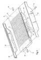
- Figure 1 is an exploded perspective view of the heat exchanger of the subject invention;
- Figure 2 is a cross sectional view of the heat exchanger shown in Figure 1;
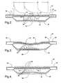
- Figure 3 is a second embodiment of the invention;
- Figure 4 is a third embodiment;
- Figure 5 is a fourth embodiment;
- Figure 6 is a fifth embodiment;
- Figure 7 is a sixth embodiment;
- Figure 8 is a fragmentary enlarged view of Figure 5 to clearly show the position of the flow interrupter at the apex of an undulation; and
- Figure 9 is a schematic of a liquid cooling system in which the heat exchanger of the subject invention may be utilized.
- A fluid heat exchanger assembly comprises a
housing 20 having aninlet 22 and anoutlet 24 and anupper portion 26 defining a top orupper wall 27 and alower portion 28 extending between theinlet 22 and theoutlet 24 for establishing a direction of flow from theinlet 22 to theoutlet 24. The assembly is used to cool anelectronic device 30 engaging or secured to thelower portion 28 of thehousing 20. As shown in Figure 3, theelectronic device 30 or component is preferably adhesively secured in arecess 29 in the bottom of thehousing 20. - A
partition 32 divides thehousing 20 into theupper portion 26 and thelower portion 28 for establishing a direction of flow of liquid coolant in acoolant passage 33 defined between theupper wall 27 and thepartition 32 from theinlet 22 to theoutlet 24 in theupper portion 26. Thehousing 20 is hermetically sealed about thepartition 32 to contain a refrigerant in thelower portion 28 for liquid-to-vapor transformation. In other words, thepartition 32 separates the refrigerant in thelower portion 28 from the liquid coolant in thecoolant passage 33 of theupper portion 26. - The
partition 32 and theupper wall 27 are undulated or corrugated transversely to the direction of flow from theinlet 22 to theoutlet 24 to define theflow passage 33. Thepartition 32 defines a bottom of thecoolant passage 33 in theupper portion 26 and theupper wall 27 of theupper portion 26 defines a top of thecoolant passage 33, which top orupper wall 27 is also undulated transversely to the direction of flow from theinlet 22 to theoutlet 24 to define thecoolant passage 33. Disposed inside thecoolant passage 33 are theflow interrupters 34 extending vertically upward into the coolant stream. The purpose of theflow interrupters 34 is to interrupt the thermal boundary layer growing from the uppercorrugated wall 27 and the lowercorrugated wall 32 of thecoolant passage 33. The interruption of the thermal boundary layer causes the heat transfer coefficient h to attain higher value at the point of interruption as indicated in Figure 2, which shows two flow interrupters each located distance L apart. As the thermal boundary layer grows the heat transfer coefficient h decreases. If theflow interrupters 34 are not provided the heat transfer coefficient attains extremely low value undermining the thermal performance of thethermosiphon 20. - In the embodiments of Figures 1-5, the V-shaped crests defining the top (upper wall27) and the bottom (partition32) of the
coolant passage 33 are vertically aligned to parallel one another so that thecoolant passage 33 has a constant gap or cross sectional area therealong, i.e., the vertical dimension between the top and bottom of theupper portion 26 remains constant between theinlet 22 to theoutlet 24. On the other hand, in the embodiment of Figure 6 the V-shaped crests defining the top and the bottom of thecoolant passage 33 are vertically offset so that thecoolant passage 33 has a variable gap or cross sectional area therealong. In the embodiment of Figure 7, the top and bottom V-shaped crests may be either but are spaced vertically farther apart adjacent theinlet 22 and theoutlet 24 than between theinlet 22 and theoutlet 24 for narrowing the volume of thecoolant passage 33 between theinlet 22 and theoutlet 24. The advantage of acoolant passage 33 having a variable gap between the undulations is that it provides additional heat transfer enhancement because of the periodic expansion and contraction of the liquid coolant flow. In the embodiment of Figure 3, the top and the bottom sag into thelower portion 28 between theinlet 22 and theoutlet 24 so that thecoolant passage 33 is closer to theelectronic device 30 between the ends thereof. Said another way, thepartition 32 sags into thelower portion 28 so that thecoolant passage 33 is closer to theelectronic device 30 between theinlet 22 and theoutlet 24. The undulatedpartition 32 and the undulatedupper wall 27 define V-shaped crests and the flow interrupters(34) extend from the apex of the V-shaped crests spaced apart a distance L. - A plurality of
fins 36 extend from the bottom of thehousing 20 for increasing heat transfer from theelectronic device 30 to the interior of thelower portion 28 of thehousing 20. Thefins 36 extend linearly across the direction of flow under thepartition 32 and between theinlet 22 and theoutlet 24 in theupper portion 26. Theheat transfer fins 36 are disposed in thelower portion 28 of thehousing 20 for transferring heat from theelectronic device 30 disposed on the exterior of thelower portion 28 of thehousing 20. Thefins 36 vary in height and, more specifically, thefins 36 are of the greatest height midway between theinlet 22 and theoutlet 24 and are of progressively lesser height from the midpoint toward theinlet 22 and theoutlet 24 respectively. Themiddle fin 36 may extend all the way to the lowercorrugated wall 32 and be brazed to it to provide reinforcement to the vapor chamber below the lowercorrugated wall 32. The embodiment of Figure 3 illustrates that thepartition 32 may sag into thelower portion 28 toward thefins 36. Thefins 36 may take the form of those disclosed in U.S. Patent 6,588,498. - In addition, heat transfer surfaces38 may extend upwardly from the
upper portion 26 for enhancing heat transfer between the liquid coolant and the environment surrounding theupper portion 26. - The
upper portion 26 of thehousing 20 is generally rectangular and thelower portion 28 of thehousing 20 is generally rectangular and generally coextensive with theupper portion 26. Arecess 29 extends into thelower portion 28 of thehousing 20 for receiving theelectronic device 30. Theentire housing 20, including theflow passage 33 with uppercorrugated wall 27 and lowercorrugated wall 32 along with endsections defining tanks 42, and the pan-shapedlower portion 28 having integrally formed therewith thefins 36 and therecess 29 for theelectronic device 30, may be extruded as a single or integral piece thereby obviating the need for various brazing operations. Sections of the extrusion are cut andend plates 44 with braze coating are stamped out of sheet stock. During the stamping of theend plates 44, various grooves are formed in theend plates 44 to receive and facilitate bonding to the edges of the extruded sections, thereby hermetically sealing theupper portion 26 andlower portions 28 of thehousing 20. A simple machining operation is used to drill holes in oneend plate 44 and in thetanks 42 of thecoolant passage 33. After welding arefrigerant charge tube 46 to the hole drilled in theend plate 44, and welding theinlet 22 andoutlet 24 to thetanks 42, the entire assembly is wired together for a brazing operation in a furnace. After the brazing operation, the assembly is ready for inspection, testing, charging and connection to a cooling system, as illustrated in Figure 8. - The liquid cooling system illustrated in Figure 8 incorporates the
heat exchanger housing 20 for cooling anelectronic device 30. Theelectronic device 30 generates an amount of heat to be dissipated and the heat is transferred from theelectronic device 30 to the bottom of theheat exchanger housing 20. The heat is then conducted from the bottom to thefins 36 and thence to the refrigerant. A working fluid mover, such as a pumpP, moves a cooling fluid, usually a liquid, through a cooling fluid storage vesselT, that stores excess cooling fluid. The pumpP moves the cooling fluid through a heat extractor or radiator assembly to dissipate heat from the cooling fluid, the heat extractor or radiator assembly including a fanF and radiatorR. The radiatorR can be of the well known type including tubes with cooling sheets between the tubes to exchange heat between the cooling fluid passing through the tubes and air forced through the radiator by the fanF. Theelectronic device 30 generates heat that is transferred through thefins 36 to the captive refrigerant sealed in thelower portion 28 of thehousing 20 to boil and vaporize the refrigerant. The vaporized refrigerant rises in thelower portion 28 of thehousing 20 and into the V-shaped cavities between the crests of thecoolant flow passage 33. The liquid coolant flowing through the undulatingcoolant passage 33 absorbs heat from the refrigerant vapor thereby condensing the vapor back into liquid refrigerant pooled in thelower portion 28 where it again absorbs heat from theelectronic device 30 to repeat the cycle. - As illustrated in Figure 2, the parameters of the
coolant passage 33 are very important. In accordance with the subject invention, the optimum value of the passage gap s is established to be given by the following relation in terms of the transport properties of the coolant as embodied in the dimensionless Prandtl number Pr, the mass flow rate ṁ and the dynamic viscosity µ of the coolant:
where the dimensionless Prandtl number is defined as
where µ is the dynamic viscosity of the coolant, cp is the isobaric specific heat of the coolant and k is the thermal conductivity of the coolant. - Knowing the flow passage gap s from Equation (1), the corrugation pitch p and the flow interrupter height a, shown in Figure 2 are determined using the following relations:


where φ is the corrugation angle shown in Figure 2. - According to the subject invention, the flow interruption length L, shown in Figure 2, is given by the relation

where w is the depth of the thermosiphon perpendicular to the plane of the paper and the remaining symbols are previously defined. - By way of an example we calculate the dimensions of the
thermosiphon 20 with a corrugation angle φ = 30° and depth w = 50 mm using the foregoing relations. Let the coolant be water flowing through theflow passage 33 at the rate ṁ= 30 gm/sec at 40 °C. At this temperature the transport properties of liquid water are µ = 6.7918 × 10⁻³ gm/cm·sec, cp = 0.999 cal/gm·°C, k = 1.4963 × 10⁻³ cal/cm·sec·°C and Pr = 4.53. Introducing the aforementioned values of ṁ = 30 gm/sec, µ = 6.7918 × 10⁻³ gm/cm·sec and Pr = 4.53 into Equation (1), we obtain the passage gap s = 0.31 mm. Next, introducing the calculated value of s = 0.31 mm together with the given value of the corrugation angle φ = 30° into Equations (2) and (3), we obtain the corrugation pitch p = 0.31 mm and theflow interrupter 34 height a ≤ 0.27 mm. Finally, introducing the calculated value of s = 0.31 mm together with the aforementioned values of φ = 30°, w = 50 mm, Pr = 4.53,ṁ = 30 gm/sec and µ =6.7918 × 10⁻³ gm/cm·sec into Equation (5), we obtain the flow interruption length L ≤ 43 mm. - Based on extensive investigation of the cooling of electronics, it is established that the most useful ranges of s, φ and L are given by the following relations:


- Consistent with these ranges of s and φ, the useful ranges of p and a can be calculated using Equations (3) and (4).
- The flow interrupters34 interrupt the growth of the thermal boundary layer on the undulated top and bottom walls of the
upper portion 26. If the thermal boundary layer is allowed to grow uninterrupted, the resistance to heat transfer progressively increases and results in progressively smaller values of the heat transfer coefficient h as indicated in Figure 2. By interrupting the thermal boundary layer growth, the thermal boundary layer is forced to restart at the point of interruption with lower thermal resistance and consequently a higher heat transfer coefficient. Accordingly, theflow interrupters 34 give rise to a saw-tooth wave variation of the heat transfer coefficient instead of a monotonically decreasing heat transfer coefficient along the flow passage as indicated in Figure 2. - The invention therefore provides a method of cooling an
electronic device 30 by disposing a refrigerant in thelower portion 28 of thehousing 20 for liquid-to-vapor transformation and transferring the heat generated by theelectronic device 30 to thelower portion 28 of ahousing 20. The method is distinguished by flowing liquid coolant over theflow interrupters 34 disposed in thecoolant flow passage 33 for interrupting thermal boundary layer to enhance heat transfer to the flow of liquid coolant through theupper portion 26 in response to heat transferred by anelectronic device 30 to thelower portion 28 of thehousing 20. - Obviously, many modifications and variations of the present invention are possible in light of the above teachings. The invention may be practiced otherwise than as specifically described within the scope of the appended claims, wherein recitations should be interpreted to cover any combination in which the incentive novelty exercises its utility.


Claims (23)
- A fluid heat exchanger assembly for cooling an electronic device(30) with a liquid coolant supplied from a heat extractor(R, F) and comprising;
a housing(20) having an inlet(22) and an outlet(24) and an upper portion(26) and a lower portion(28) with said inlet(22) and said outlet(24) being in said upper portion(26),
a partition(32) dividing said housing(20) into said upper portion(26) having an upper wall(27) and said lower portion(28) for establishing a direction of flow in a coolant passage(33) from said inlet(22) to said outlet(24) in said upper portion(26) between said partition(32) and said upper wall(27),
a refrigerant disposed in said lower portion(28) of said housing(20) for liquid-to-vapor transformation,
said housing(20) being hermetically sealed about said partition(32) to separate said refrigerant in said lower portion(28) from the liquid coolant in said upper portion(26), and
flow interrupters(34) disposed in said coolant passage(33) for interrupting thermal boundary layer to enhance thermal heat transfer to the flow of liquid coolant through said coolant passage(33) of said upper portion(26) in response to heat transferred by an electronic device(30) to said lower portion(28) of said housing(20). - An assembly as set forth in claim 1 including a projection into said coolant passage(33) defining said flow interrupters(34).
- An assembly as set forth in claim 2 wherein said partition(32) and said upper wall(27) comprise a thin gage metal.
- An assembly as set forth in claim 2 wherein said partition(32) is undulated transversely to said direction of flow from said inlet(22) to said outlet(24).
- An assembly as set forth in claim 4 wherein said undulated partition(32) comprise V-shaped crests and said flow interrupters(34) extend from V-shaped crests.
- An assembly as set forth in claim 4 wherein said partition(32) defines a bottom of said coolant passage(33) in said upper portion(26) and said upper wall(27) defines the top of said coolant passage(33), said upper wall(27) also being undulated transversely to said direction of flow from said inlet(22) to said outlet(24).
- An assembly as set forth in claim 6 wherein said undulated partition(32) and said undulated upper wall(27) define V-shaped crests and said flow interrupters(34) extend from said V-shaped crests.
- An assembly as set forth in claim 7 wherein said V-shaped crests defining said top and said bottom of said coolant passage(33) are vertically aligned to parallel one another so that said coolant passage(33) has a constant gap therealong.
- An assembly as set forth in claim 8 wherein said top and said bottom sag into said lower portion(28) between said inlet(22) and said outlet(24).
- An assembly as set forth in claim 7 wherein said V-shaped crests defining said top and said bottom of said coolant passage(33) are vertically offset so that said coolant passage(33) has a variable cross sectional area therealong.
- An assembly as set forth in claim 7 wherein said V-shaped crests defining said top and said bottom of said coolant passage(33) are spaced vertically farther apart adjacent said inlet(22) and said outlet(24) than between said inlet(22) and said outlet(24) for narrowing the volume of said coolant passage(33) between said inlet(22) and said outlet(24).
- An assembly as set forth in claim 1 wherein said partition(32) sags into said lower portion(28) so that said coolant passage(33) is closer to the electronic device(30) between said inlet(22) and said outlet(24).
- An assembly as set forth in claim 6 including heat transfer fins(36) disposed in said lower portion(28) of said housing(20) for transferring heat from an electronic device(30) disposed on the exterior of said lower portion(28) of said housing(20).
- An assembly as set forth in claim 13 wherein said fins(36) vary in height.
- An assembly as set forth in claim 14 wherein the middle fin(36) extends vertically all the way to the partion wall(32) to reinforce the said lower portion(28).
- An assembly as set forth in claim 14 wherein said fins(36) are of the greatest height midway between said inlet(22) and said outlet(24) and are of progressively lesser height toward said inlet(22) and said outlet(24) respectively.
- An assembly as set forth in claim 15 wherein said partition(32) sags into said lower portion(28) toward said fins(36).
- An assembly as set forth in claim 6 including heat transfer surfaces(38) extending upwardly from said upper wall(27) of said upper portion(26) for enhancing heat transfer between said liquid coolant and the environment surrounding said upper portion(26).
- An assembly as set forth in claim 17 including a recess(29) in said lower portion(28) for receiving the electronic device(30).
- An assembly as set forth in claim 1 wherein said upper portion(26) of said housing(20) is generally rectangular and said lower portion(28) of said housing(20) is generally coextensive with said upper portion(26).
- An assembly as set forth in claim 8 wherein the optimum dimensions are calculable using the relations

where s is the flow passage gap, ṁ is the mass flow rate of the coolant passage(33), µ is the dynamic viscosity of the coolant and the dimensionless Prandtl number Pr is defined as
where µ is the dynamic viscosity of the coolant, cp is the isobaric specific heat of the coolant and k is the thermal conductivity of the coolant.
where p is the corrugation pitch, s is the flow passage(33) gap calculable using Equation (1) and φ is the corrugation angle.
where a is the flow interrupter(34) height, s is the flow passage(33) gap calculable using Equation (1) and φ is the corrugation angle.
where L is the flow interruption length, ṁ is the mass flow rate of the coolant passage(33), cp is the isobaric specific heat of the coolant, k is the thermal conductivity of the coolant, s is the flow passage(33) gap calculable using Equation (1), φ is the corrugation angle and w is the depth of the thermosiphon perpendicular to the plane of the paper. - An assembly as set forth in claim 8 wherein


with p being the corrugation pitch in the upper flow passage wall(27) and the lower corrugation wall(32) of the coolant flow passage(33), s being the flow passage gap between the top and bottom of the coolant passage(33), φ the corrugation angle of the V-shaped passage wall(33) and L being the flow interruption length in the flow passage(33)marked by the flow interrupters(34). - A method of cooling an electronic device(30) comprising the steps of; generating heat by an electronic device(30),
transferring the heat generated by the electronic device(30) to the lower portion(28) of a housing(20),
disposing a refrigerant in the lower portion(28) of the housing(20) for liquid-to-vapor transformation, and
flowing liquid coolant over flow interrupters(34) disposed in an upper portion(26) of the housing(20) for interrupting thermal boundary layer to enhance thermal heat transfer to the flow of liquid coolant through the upper portion(26) in response to heat transferred by an electronic device(30) to the lower portion(28) of the housing(20).


Applications Claiming Priority (1)
| Application Number | Priority Date | Filing Date | Title |
|---|---|---|---|
| US11/040,989US7506682B2 (en) | 2005-01-21 | 2005-01-21 | Liquid cooled thermosiphon for electronic components |
Publications (2)
| Publication Number | Publication Date |
|---|---|
| EP1684564A1true EP1684564A1 (en) | 2006-07-26 |
| EP1684564B1 EP1684564B1 (en) | 2007-11-21 |
Family
ID=36123542
Family Applications (1)
| Application Number | Title | Priority Date | Filing Date |
|---|---|---|---|
| EP06075006ANot-in-forceEP1684564B1 (en) | 2005-01-21 | 2006-01-04 | Liquid cooled thermosiphon for electronic components |
Country Status (3)
| Country | Link |
|---|---|
| US (1) | US7506682B2 (en) |
| EP (1) | EP1684564B1 (en) |
| DE (1) | DE602006000243T2 (en) |
Cited By (4)
| Publication number | Priority date | Publication date | Assignee | Title |
|---|---|---|---|---|
| CN111352490A (en)* | 2020-02-29 | 2020-06-30 | 苏州浪潮智能科技有限公司 | A liquid cooling device for a server with a central jet and an adjustable return tank |
| CN112888267A (en)* | 2021-02-05 | 2021-06-01 | 华南理工大学 | Ultrathin flexible vapor chamber and manufacturing method |
| WO2022015228A1 (en)* | 2020-07-15 | 2022-01-20 | Telefonaktiebolaget Lm Ericsson (Publ) | Heat sink with bulk heat isolation |
| TWI786674B (en)* | 2021-06-09 | 2022-12-11 | 英業達股份有限公司 | Electronic device and heat dissipation assembly |
Families Citing this family (27)
| Publication number | Priority date | Publication date | Assignee | Title |
|---|---|---|---|---|
| US20060196640A1 (en)* | 2004-12-01 | 2006-09-07 | Convergence Technologies Limited | Vapor chamber with boiling-enhanced multi-wick structure |
| US20070227701A1 (en)* | 2006-03-31 | 2007-10-04 | Bhatti Mohinder S | Thermosiphon with flexible boiler plate |
| US8528628B2 (en)* | 2007-02-08 | 2013-09-10 | Olantra Fund X L.L.C. | Carbon-based apparatus for cooling of electronic devices |
| US20090139698A1 (en)* | 2007-12-03 | 2009-06-04 | Watronx, Inc. (Aka Onscreen Technologies, Inc.) | Carbon-based waterlock with attached heat-exchanger for cooling of electronic devices |
| US20100002392A1 (en)* | 2008-07-07 | 2010-01-07 | I-Ming Liu | Assembled Heat Sink Structure |
| TWI359635B (en)* | 2008-08-07 | 2012-03-01 | Inventec Corp | Wind-guiding cover |
| US7796389B2 (en)* | 2008-11-26 | 2010-09-14 | General Electric Company | Method and apparatus for cooling electronics |
| CN102042777B (en)* | 2009-10-15 | 2013-06-05 | 富准精密工业(深圳)有限公司 | Flat plate type heat pipe |
| CN102062553B (en)* | 2009-11-12 | 2013-12-04 | 富准精密工业(深圳)有限公司 | Flat plate type heat pipe |
| JP6216964B2 (en)* | 2011-08-09 | 2017-10-25 | 三菱アルミニウム株式会社 | Clad material for cooler and cooler for heating element |
| EP2605345B1 (en)* | 2011-12-13 | 2021-04-28 | Alcatel Lucent | Thermal management of photonics assemblies |
| ES2638857T3 (en)* | 2012-03-28 | 2017-10-24 | Abb Research Ltd. | Heat exchanger for traction converters |
| JP6403664B2 (en) | 2012-05-07 | 2018-10-10 | フォノニック デバイセズ、インク | Thermoelectric heat exchanger components including protective heat spreading lid and optimal thermal interface resistance |
| US20130291555A1 (en) | 2012-05-07 | 2013-11-07 | Phononic Devices, Inc. | Thermoelectric refrigeration system control scheme for high efficiency performance |
| US20140054009A1 (en)* | 2012-08-27 | 2014-02-27 | Asustek Computer Inc. | Cooling plate and water cooling device having the same |
| US9593871B2 (en) | 2014-07-21 | 2017-03-14 | Phononic Devices, Inc. | Systems and methods for operating a thermoelectric module to increase efficiency |
| US10458683B2 (en) | 2014-07-21 | 2019-10-29 | Phononic, Inc. | Systems and methods for mitigating heat rejection limitations of a thermoelectric module |
| NL2014466B1 (en)* | 2015-03-16 | 2017-01-13 | Nerdalize B V | Module for cooling a heat generating component. |
| CN110024500B (en)* | 2017-02-03 | 2020-11-17 | 惠普发展公司,有限责任合伙企业 | Thermal management using steam and isolation chambers |
| DE102017215952B3 (en) | 2017-09-11 | 2019-02-07 | F & S Prozessautomation GmbH | Heat sink with two hollow bodies and cooling arrangement |
| US11435144B2 (en)* | 2019-08-05 | 2022-09-06 | Asia Vital Components (China) Co., Ltd. | Heat dissipation device |
| JP7305512B2 (en)* | 2019-10-17 | 2023-07-10 | 新光電気工業株式会社 | Loop type heat pipe and its manufacturing method |
| US11259447B2 (en)* | 2019-12-27 | 2022-02-22 | Baidu Usa Llc | Composite liquid cooling device |
| CN113242680A (en) | 2021-05-28 | 2021-08-10 | 惠州汉旭五金塑胶科技有限公司 | Liquid cooling radiator capable of improving radiating effect |
| CN115443025B (en)* | 2021-06-02 | 2025-06-06 | 英业达科技有限公司 | Electronic devices and heat dissipation components |
| US12341082B2 (en)* | 2021-08-06 | 2025-06-24 | Baidu Usa Llc | Chip cooling package with multiple fluid paths |
| CN114126371B (en)* | 2021-11-30 | 2025-09-05 | 经纬恒润(天津)研究开发有限公司 | Enhanced heat exchange control method and device |
Citations (3)
| Publication number | Priority date | Publication date | Assignee | Title |
|---|---|---|---|---|
| US4704658A (en)* | 1985-04-30 | 1987-11-03 | Fujitsu Limited | Evaporation cooling module for semiconductor devices |
| US6588498B1 (en)* | 2002-07-18 | 2003-07-08 | Delphi Technologies, Inc. | Thermosiphon for electronics cooling with high performance boiling and condensing surfaces |
| US20040163798A1 (en)* | 2003-02-25 | 2004-08-26 | Debashis Ghosh | Compact thermosiphon for dissipating heat generated by electronic components |
Family Cites Families (26)
| Publication number | Priority date | Publication date | Assignee | Title |
|---|---|---|---|---|
| US2083611A (en) | 1931-12-05 | 1937-06-15 | Carrier Corp | Cooling system |
| US3415315A (en) | 1966-06-29 | 1968-12-10 | Borg Warner | Heat exchanger |
| US3511310A (en) | 1968-04-15 | 1970-05-12 | Varian Associates | Integral vapor cooling system |
| US3512582A (en)* | 1968-07-15 | 1970-05-19 | Ibm | Immersion cooling system for modularly packaged components |
| DE2102254B2 (en)* | 1971-01-19 | 1973-05-30 | Robert Bosch Gmbh, 7000 Stuttgart | COOLING DEVICE FOR POWER SEMICONDUCTOR COMPONENTS |
| US3800868A (en)* | 1972-04-14 | 1974-04-02 | Curtiss Wright Corp | Heat exchanger |
| US3906261A (en) | 1973-06-12 | 1975-09-16 | Mitsubishi Electric Corp | Linear acceleration apparatus with cooling system |
| JPS5512740B2 (en) | 1974-03-15 | 1980-04-03 | ||
| US4138692A (en) | 1977-09-12 | 1979-02-06 | International Business Machines Corporation | Gas encapsulated cooling module |
| US4173996A (en) | 1978-09-05 | 1979-11-13 | General Electric Company | Heat exchanger arrangement for vaporization cooled transfomers |
| US4260014A (en) | 1979-04-09 | 1981-04-07 | International Telephone And Telegraph Corporation | Ebullient cooled power devices |
| US4246597A (en) | 1979-06-29 | 1981-01-20 | International Business Machines Corporation | Air cooled multi-chip module having a heat conductive piston spring loaded against the chips |
| US4381032A (en)* | 1981-04-23 | 1983-04-26 | Cutchaw John M | Apparatus for cooling high-density integrated circuit packages |
| JPS60125203A (en) | 1983-12-13 | 1985-07-04 | Nitto Electric Ind Co Ltd | Thermoparation device |
| US4884630A (en)* | 1988-07-14 | 1989-12-05 | Microelectronics And Computer Technology Corporation | End fed liquid heat exchanger for an electronic component |
| DE4121534C2 (en) | 1990-06-30 | 1998-10-08 | Toshiba Kawasaki Kk | Cooler |
| JP2724033B2 (en) | 1990-07-11 | 1998-03-09 | 株式会社日立製作所 | Semiconductor module |
| EP0552538B1 (en) | 1991-12-16 | 1996-03-13 | AT&T Corp. | Narrow channel finned heat sinking for cooling high power electronic components |
| US5168921A (en) | 1991-12-23 | 1992-12-08 | Thermacore, Inc. | Cooling plate with internal expandable heat pipe |
| US5704416A (en)* | 1993-09-10 | 1998-01-06 | Aavid Laboratories, Inc. | Two phase component cooler |
| US5529115A (en) | 1994-07-14 | 1996-06-25 | At&T Global Information Solutions Company | Integrated circuit cooling device having internal cooling conduit |
| US6062302A (en) | 1997-09-30 | 2000-05-16 | Lucent Technologies Inc. | Composite heat sink |
| US6410982B1 (en) | 1999-11-12 | 2002-06-25 | Intel Corporation | Heatpipesink having integrated heat pipe and heat sink |
| US6808015B2 (en)* | 2000-03-24 | 2004-10-26 | Denso Corporation | Boiling cooler for cooling heating element by heat transfer with boiling |
| US6422307B1 (en) | 2001-07-18 | 2002-07-23 | Delphi Technologies, Inc. | Ultra high fin density heat sink for electronics cooling |
| JP2003060371A (en) | 2001-08-16 | 2003-02-28 | Nec Corp | Radiating structure of communication apparatus cabinet |
- 2005
- 2005-01-21USUS11/040,989patent/US7506682B2/ennot_activeExpired - Fee Related
- 2006
- 2006-01-04EPEP06075006Apatent/EP1684564B1/ennot_activeNot-in-force
- 2006-01-04DEDE602006000243Tpatent/DE602006000243T2/enactiveActive
Patent Citations (3)
| Publication number | Priority date | Publication date | Assignee | Title |
|---|---|---|---|---|
| US4704658A (en)* | 1985-04-30 | 1987-11-03 | Fujitsu Limited | Evaporation cooling module for semiconductor devices |
| US6588498B1 (en)* | 2002-07-18 | 2003-07-08 | Delphi Technologies, Inc. | Thermosiphon for electronics cooling with high performance boiling and condensing surfaces |
| US20040163798A1 (en)* | 2003-02-25 | 2004-08-26 | Debashis Ghosh | Compact thermosiphon for dissipating heat generated by electronic components |
Cited By (5)
| Publication number | Priority date | Publication date | Assignee | Title |
|---|---|---|---|---|
| CN111352490A (en)* | 2020-02-29 | 2020-06-30 | 苏州浪潮智能科技有限公司 | A liquid cooling device for a server with a central jet and an adjustable return tank |
| CN111352490B (en)* | 2020-02-29 | 2021-04-27 | 苏州浪潮智能科技有限公司 | A liquid cooling device for a server with a central jet and an adjustable return tank |
| WO2022015228A1 (en)* | 2020-07-15 | 2022-01-20 | Telefonaktiebolaget Lm Ericsson (Publ) | Heat sink with bulk heat isolation |
| CN112888267A (en)* | 2021-02-05 | 2021-06-01 | 华南理工大学 | Ultrathin flexible vapor chamber and manufacturing method |
| TWI786674B (en)* | 2021-06-09 | 2022-12-11 | 英業達股份有限公司 | Electronic device and heat dissipation assembly |
Also Published As
| Publication number | Publication date |
|---|---|
| DE602006000243D1 (en) | 2008-01-03 |
| EP1684564B1 (en) | 2007-11-21 |
| DE602006000243T2 (en) | 2008-10-02 |
| US7506682B2 (en) | 2009-03-24 |
| US20060162904A1 (en) | 2006-07-27 |
Similar Documents
| Publication | Publication Date | Title |
|---|---|---|
| EP1684564B1 (en) | Liquid cooled thermosiphon for electronic components | |
| US7604040B2 (en) | Integrated liquid cooled heat sink for electronic components | |
| US7077189B1 (en) | Liquid cooled thermosiphon with flexible coolant tubes | |
| US7509995B2 (en) | Heat dissipation element for cooling electronic devices | |
| US20060162903A1 (en) | Liquid cooled thermosiphon with flexible partition | |
| US7204299B2 (en) | Cooling assembly with sucessively contracting and expanding coolant flow | |
| EP1383170B1 (en) | Thermosiphon for electronics cooling with nonuniform airflow | |
| US7556086B2 (en) | Orientation-independent thermosyphon heat spreader | |
| US6714413B1 (en) | Compact thermosiphon with enhanced condenser for electronics cooling | |
| US7650928B2 (en) | High performance compact thermosiphon with integrated boiler plate | |
| US5737923A (en) | Thermoelectric device with evaporating/condensing heat exchanger | |
| US7106589B2 (en) | Heat sink, assembly, and method of making | |
| US7556089B2 (en) | Liquid cooled thermosiphon with condenser coil running in and out of liquid refrigerant | |
| US20070246193A1 (en) | Orientation insensitive thermosiphon of v-configuration | |
| EP1860523A2 (en) | Orientation insensitive thermosiphon capable of operation in upside down position | |
| EP1519646A2 (en) | Use of graphite foam materials in pumped liquid, two phase cooling, cold plates | |
| US20070227701A1 (en) | Thermosiphon with flexible boiler plate | |
| US7556088B2 (en) | Thermosiphon for laptop computer | |
| CN111818756B (en) | Heat exchanger with integrated two-phase radiator | |
| CN100582637C (en) | Micro heat pipe with wedge capillaries | |
| US20070151275A1 (en) | Methods and apparatus for microelectronic cooling using a miniaturized vapor compression system | |
| KR200337381Y1 (en) | cooling equipments using a separated type heatpipes | |
| JPH07176662A (en) | Boiling/cooling unit |
Legal Events
| Date | Code | Title | Description |
|---|---|---|---|
| PUAI | Public reference made under article 153(3) epc to a published international application that has entered the european phase | Free format text:ORIGINAL CODE: 0009012 | |
| AK | Designated contracting states | Kind code of ref document:A1 Designated state(s):AT BE BG CH CY CZ DE DK EE ES FI FR GB GR HU IE IS IT LI LT LU LV MC NL PL PT RO SE SI SK TR | |
| AX | Request for extension of the european patent | Extension state:AL BA HR MK YU | |
| 17P | Request for examination filed | Effective date:20070126 | |
| AKX | Designation fees paid | Designated state(s):AT BE BG CH CY CZ DE DK EE ES FI FR GB GR HU IE IS IT LI LT LU LV MC NL PL PT RO SE SI SK TR | |
| GRAP | Despatch of communication of intention to grant a patent | Free format text:ORIGINAL CODE: EPIDOSNIGR1 | |
| GRAS | Grant fee paid | Free format text:ORIGINAL CODE: EPIDOSNIGR3 | |
| GRAA | (expected) grant | Free format text:ORIGINAL CODE: 0009210 | |
| AK | Designated contracting states | Kind code of ref document:B1 Designated state(s):AT BE BG CH CY CZ DE DK EE ES FI FR GB GR HU IE IS IT LI LT LU LV MC NL PL PT RO SE SI SK TR | |
| REG | Reference to a national code | Ref country code:GB Ref legal event code:FG4D | |
| REG | Reference to a national code | Ref country code:IE Ref legal event code:FG4D | |
| REG | Reference to a national code | Ref country code:CH Ref legal event code:EP | |
| REF | Corresponds to: | Ref document number:602006000243 Country of ref document:DE Date of ref document:20080103 Kind code of ref document:P | |
| PG25 | Lapsed in a contracting state [announced via postgrant information from national office to epo] | Ref country code:SE Free format text:LAPSE BECAUSE OF FAILURE TO SUBMIT A TRANSLATION OF THE DESCRIPTION OR TO PAY THE FEE WITHIN THE PRESCRIBED TIME-LIMIT Effective date:20080221 Ref country code:NL Free format text:LAPSE BECAUSE OF FAILURE TO SUBMIT A TRANSLATION OF THE DESCRIPTION OR TO PAY THE FEE WITHIN THE PRESCRIBED TIME-LIMIT Effective date:20071121 Ref country code:ES Free format text:LAPSE BECAUSE OF FAILURE TO SUBMIT A TRANSLATION OF THE DESCRIPTION OR TO PAY THE FEE WITHIN THE PRESCRIBED TIME-LIMIT Effective date:20080304 Ref country code:CH Free format text:LAPSE BECAUSE OF FAILURE TO SUBMIT A TRANSLATION OF THE DESCRIPTION OR TO PAY THE FEE WITHIN THE PRESCRIBED TIME-LIMIT Effective date:20071121 Ref country code:LI Free format text:LAPSE BECAUSE OF FAILURE TO SUBMIT A TRANSLATION OF THE DESCRIPTION OR TO PAY THE FEE WITHIN THE PRESCRIBED TIME-LIMIT Effective date:20071121 | |
| NLV1 | Nl: lapsed or annulled due to failure to fulfill the requirements of art. 29p and 29m of the patents act | ||
| PG25 | Lapsed in a contracting state [announced via postgrant information from national office to epo] | Ref country code:IS Free format text:LAPSE BECAUSE OF FAILURE TO SUBMIT A TRANSLATION OF THE DESCRIPTION OR TO PAY THE FEE WITHIN THE PRESCRIBED TIME-LIMIT Effective date:20080321 Ref country code:FI Free format text:LAPSE BECAUSE OF FAILURE TO SUBMIT A TRANSLATION OF THE DESCRIPTION OR TO PAY THE FEE WITHIN THE PRESCRIBED TIME-LIMIT Effective date:20071121 Ref country code:BG Free format text:LAPSE BECAUSE OF FAILURE TO SUBMIT A TRANSLATION OF THE DESCRIPTION OR TO PAY THE FEE WITHIN THE PRESCRIBED TIME-LIMIT Effective date:20080221 Ref country code:SI Free format text:LAPSE BECAUSE OF FAILURE TO SUBMIT A TRANSLATION OF THE DESCRIPTION OR TO PAY THE FEE WITHIN THE PRESCRIBED TIME-LIMIT Effective date:20071121 Ref country code:PL Free format text:LAPSE BECAUSE OF FAILURE TO SUBMIT A TRANSLATION OF THE DESCRIPTION OR TO PAY THE FEE WITHIN THE PRESCRIBED TIME-LIMIT Effective date:20071121 Ref country code:LV Free format text:LAPSE BECAUSE OF FAILURE TO SUBMIT A TRANSLATION OF THE DESCRIPTION OR TO PAY THE FEE WITHIN THE PRESCRIBED TIME-LIMIT Effective date:20071121 Ref country code:LT Free format text:LAPSE BECAUSE OF FAILURE TO SUBMIT A TRANSLATION OF THE DESCRIPTION OR TO PAY THE FEE WITHIN THE PRESCRIBED TIME-LIMIT Effective date:20071121 | |
| REG | Reference to a national code | Ref country code:CH Ref legal event code:PL | |
| PG25 | Lapsed in a contracting state [announced via postgrant information from national office to epo] | Ref country code:AT Free format text:LAPSE BECAUSE OF FAILURE TO SUBMIT A TRANSLATION OF THE DESCRIPTION OR TO PAY THE FEE WITHIN THE PRESCRIBED TIME-LIMIT Effective date:20071121 | |
| ET | Fr: translation filed | ||
| PG25 | Lapsed in a contracting state [announced via postgrant information from national office to epo] | Ref country code:CZ Free format text:LAPSE BECAUSE OF FAILURE TO SUBMIT A TRANSLATION OF THE DESCRIPTION OR TO PAY THE FEE WITHIN THE PRESCRIBED TIME-LIMIT Effective date:20071121 Ref country code:DK Free format text:LAPSE BECAUSE OF FAILURE TO SUBMIT A TRANSLATION OF THE DESCRIPTION OR TO PAY THE FEE WITHIN THE PRESCRIBED TIME-LIMIT Effective date:20071121 | |
| PG25 | Lapsed in a contracting state [announced via postgrant information from national office to epo] | Ref country code:SK Free format text:LAPSE BECAUSE OF FAILURE TO SUBMIT A TRANSLATION OF THE DESCRIPTION OR TO PAY THE FEE WITHIN THE PRESCRIBED TIME-LIMIT Effective date:20071121 Ref country code:RO Free format text:LAPSE BECAUSE OF FAILURE TO SUBMIT A TRANSLATION OF THE DESCRIPTION OR TO PAY THE FEE WITHIN THE PRESCRIBED TIME-LIMIT Effective date:20071121 Ref country code:BE Free format text:LAPSE BECAUSE OF FAILURE TO SUBMIT A TRANSLATION OF THE DESCRIPTION OR TO PAY THE FEE WITHIN THE PRESCRIBED TIME-LIMIT Effective date:20071121 Ref country code:MC Free format text:LAPSE BECAUSE OF NON-PAYMENT OF DUE FEES Effective date:20080131 | |
| PLBE | No opposition filed within time limit | Free format text:ORIGINAL CODE: 0009261 | |
| STAA | Information on the status of an ep patent application or granted ep patent | Free format text:STATUS: NO OPPOSITION FILED WITHIN TIME LIMIT | |
| PG25 | Lapsed in a contracting state [announced via postgrant information from national office to epo] | Ref country code:PT Free format text:LAPSE BECAUSE OF FAILURE TO SUBMIT A TRANSLATION OF THE DESCRIPTION OR TO PAY THE FEE WITHIN THE PRESCRIBED TIME-LIMIT Effective date:20080421 | |
| 26N | No opposition filed | Effective date:20080822 | |
| PG25 | Lapsed in a contracting state [announced via postgrant information from national office to epo] | Ref country code:IE Free format text:LAPSE BECAUSE OF NON-PAYMENT OF DUE FEES Effective date:20080104 Ref country code:GR Free format text:LAPSE BECAUSE OF FAILURE TO SUBMIT A TRANSLATION OF THE DESCRIPTION OR TO PAY THE FEE WITHIN THE PRESCRIBED TIME-LIMIT Effective date:20080222 Ref country code:EE Free format text:LAPSE BECAUSE OF FAILURE TO SUBMIT A TRANSLATION OF THE DESCRIPTION OR TO PAY THE FEE WITHIN THE PRESCRIBED TIME-LIMIT Effective date:20071121 | |
| PG25 | Lapsed in a contracting state [announced via postgrant information from national office to epo] | Ref country code:CY Free format text:LAPSE BECAUSE OF FAILURE TO SUBMIT A TRANSLATION OF THE DESCRIPTION OR TO PAY THE FEE WITHIN THE PRESCRIBED TIME-LIMIT Effective date:20071121 | |
| PGFP | Annual fee paid to national office [announced via postgrant information from national office to epo] | Ref country code:FR Payment date:20100208 Year of fee payment:5 | |
| PGFP | Annual fee paid to national office [announced via postgrant information from national office to epo] | Ref country code:DE Payment date:20091231 Year of fee payment:5 | |
| PG25 | Lapsed in a contracting state [announced via postgrant information from national office to epo] | Ref country code:LU Free format text:LAPSE BECAUSE OF NON-PAYMENT OF DUE FEES Effective date:20080104 Ref country code:HU Free format text:LAPSE BECAUSE OF FAILURE TO SUBMIT A TRANSLATION OF THE DESCRIPTION OR TO PAY THE FEE WITHIN THE PRESCRIBED TIME-LIMIT Effective date:20080522 | |
| PG25 | Lapsed in a contracting state [announced via postgrant information from national office to epo] | Ref country code:TR Free format text:LAPSE BECAUSE OF FAILURE TO SUBMIT A TRANSLATION OF THE DESCRIPTION OR TO PAY THE FEE WITHIN THE PRESCRIBED TIME-LIMIT Effective date:20071121 | |
| GBPC | Gb: european patent ceased through non-payment of renewal fee | Effective date:20100104 | |
| PG25 | Lapsed in a contracting state [announced via postgrant information from national office to epo] | Ref country code:GB Free format text:LAPSE BECAUSE OF NON-PAYMENT OF DUE FEES Effective date:20100104 | |
| PG25 | Lapsed in a contracting state [announced via postgrant information from national office to epo] | Ref country code:IT Free format text:LAPSE BECAUSE OF NON-PAYMENT OF DUE FEES Effective date:20080131 | |
| REG | Reference to a national code | Ref country code:FR Ref legal event code:ST Effective date:20110930 | |
| PG25 | Lapsed in a contracting state [announced via postgrant information from national office to epo] | Ref country code:FR Free format text:LAPSE BECAUSE OF NON-PAYMENT OF DUE FEES Effective date:20110131 | |
| REG | Reference to a national code | Ref country code:DE Ref legal event code:R119 Ref document number:602006000243 Country of ref document:DE Effective date:20110802 | |
| PG25 | Lapsed in a contracting state [announced via postgrant information from national office to epo] | Ref country code:DE Free format text:LAPSE BECAUSE OF NON-PAYMENT OF DUE FEES Effective date:20110802 |