EP1684544B1 - Eletroacoustic transducer mounting in shells of personal communication devices - Google Patents
Eletroacoustic transducer mounting in shells of personal communication devicesDownload PDFInfo
- Publication number
- EP1684544B1 EP1684544B1EP06000287AEP06000287AEP1684544B1EP 1684544 B1EP1684544 B1EP 1684544B1EP 06000287 AEP06000287 AEP 06000287AEP 06000287 AEP06000287 AEP 06000287AEP 1684544 B1EP1684544 B1EP 1684544B1
- Authority
- EP
- European Patent Office
- Prior art keywords
- miniature
- housing
- transducer
- compartment
- loudspeaker
- Prior art date
- Legal status (The legal status is an assumption and is not a legal conclusion. Google has not performed a legal analysis and makes no representation as to the accuracy of the status listed.)
- Not-in-force
Links
- 238000004891communicationMethods0.000titleclaimsabstractdescription31
- 238000000034methodMethods0.000claimsdescription20
- 239000000725suspensionSubstances0.000claimsdescription15
- 230000008878couplingEffects0.000claimsdescription8
- 238000010168coupling processMethods0.000claimsdescription8
- 238000005859coupling reactionMethods0.000claimsdescription8
- 230000013011matingEffects0.000claimsdescription8
- 238000007789sealingMethods0.000description10
- 239000012528membraneSubstances0.000description7
- 239000004020conductorSubstances0.000description6
- 210000000613ear canalAnatomy0.000description6
- 238000005516engineering processMethods0.000description6
- 229910000679solderInorganic materials0.000description6
- 230000008901benefitEffects0.000description3
- 238000013016dampingMethods0.000description3
- 239000000463materialSubstances0.000description3
- 230000008439repair processEffects0.000description3
- VYPSYNLAJGMNEJ-UHFFFAOYSA-NSilicium dioxideChemical compoundO=[Si]=OVYPSYNLAJGMNEJ-UHFFFAOYSA-N0.000description2
- 239000000853adhesiveSubstances0.000description2
- 238000010276constructionMethods0.000description2
- 230000002950deficientEffects0.000description2
- 230000000694effectsEffects0.000description2
- 239000006260foamSubstances0.000description2
- 239000011521glassSubstances0.000description2
- 238000004519manufacturing processMethods0.000description2
- 230000008569processEffects0.000description2
- 239000011347resinSubstances0.000description2
- 229920005989resinPolymers0.000description2
- 229910052814silicon oxideInorganic materials0.000description2
- 238000003466weldingMethods0.000description2
- JBRZTFJDHDCESZ-UHFFFAOYSA-NAsGaChemical compound[As]#[Ga]JBRZTFJDHDCESZ-UHFFFAOYSA-N0.000description1
- RYGMFSIKBFXOCR-UHFFFAOYSA-NCopperChemical compound[Cu]RYGMFSIKBFXOCR-UHFFFAOYSA-N0.000description1
- 239000004593EpoxySubstances0.000description1
- 229910001218Gallium arsenideInorganic materials0.000description1
- 229910052581Si3N4Inorganic materials0.000description1
- 230000009471actionEffects0.000description1
- 238000004026adhesive bondingMethods0.000description1
- 230000001070adhesive effectEffects0.000description1
- 229910052782aluminiumInorganic materials0.000description1
- 239000004411aluminiumSubstances0.000description1
- XAGFODPZIPBFFR-UHFFFAOYSA-NaluminiumChemical compound[Al]XAGFODPZIPBFFR-UHFFFAOYSA-N0.000description1
- 230000004888barrier functionEffects0.000description1
- 230000015572biosynthetic processEffects0.000description1
- 230000000903blocking effectEffects0.000description1
- 210000002939cerumenAnatomy0.000description1
- 238000011109contaminationMethods0.000description1
- 229910052802copperInorganic materials0.000description1
- 239000010949copperSubstances0.000description1
- 230000006378damageEffects0.000description1
- 230000000994depressogenic effectEffects0.000description1
- 238000013461designMethods0.000description1
- 238000001514detection methodMethods0.000description1
- 239000000428dustSubstances0.000description1
- -1for preventing dirtSubstances0.000description1
- 239000007788liquidSubstances0.000description1
- 238000001459lithographyMethods0.000description1
- 230000007257malfunctionEffects0.000description1
- 238000005259measurementMethods0.000description1
- 230000010355oscillationEffects0.000description1
- 229910021420polycrystalline siliconInorganic materials0.000description1
- 230000009467reductionEffects0.000description1
- 239000012858resilient materialSubstances0.000description1
- 239000004065semiconductorSubstances0.000description1
- 230000035939shockEffects0.000description1
- 229910052710siliconInorganic materials0.000description1
- 239000010703siliconSubstances0.000description1
- HQVNEWCFYHHQES-UHFFFAOYSA-Nsilicon nitrideChemical compoundN12[Si]34N5[Si]62N3[Si]51N64HQVNEWCFYHHQES-UHFFFAOYSA-N0.000description1
- 238000005476solderingMethods0.000description1
- 239000007787solidSubstances0.000description1
- 238000012549trainingMethods0.000description1
- 238000013519translationMethods0.000description1
Images


Classifications
- H—ELECTRICITY
- H04—ELECTRIC COMMUNICATION TECHNIQUE
- H04R—LOUDSPEAKERS, MICROPHONES, GRAMOPHONE PICK-UPS OR LIKE ACOUSTIC ELECTROMECHANICAL TRANSDUCERS; DEAF-AID SETS; PUBLIC ADDRESS SYSTEMS
- H04R9/00—Transducers of moving-coil, moving-strip, or moving-wire type
- H04R9/06—Loudspeakers
- H04R9/063—Loudspeakers using a plurality of acoustic drivers
- H—ELECTRICITY
- H04—ELECTRIC COMMUNICATION TECHNIQUE
- H04R—LOUDSPEAKERS, MICROPHONES, GRAMOPHONE PICK-UPS OR LIKE ACOUSTIC ELECTROMECHANICAL TRANSDUCERS; DEAF-AID SETS; PUBLIC ADDRESS SYSTEMS
- H04R11/00—Transducers of moving-armature or moving-core type
- H04R11/02—Loudspeakers
- H—ELECTRICITY
- H04—ELECTRIC COMMUNICATION TECHNIQUE
- H04R—LOUDSPEAKERS, MICROPHONES, GRAMOPHONE PICK-UPS OR LIKE ACOUSTIC ELECTROMECHANICAL TRANSDUCERS; DEAF-AID SETS; PUBLIC ADDRESS SYSTEMS
- H04R25/00—Deaf-aid sets, i.e. electro-acoustic or electro-mechanical hearing aids; Electric tinnitus maskers providing an auditory perception
- H04R25/48—Deaf-aid sets, i.e. electro-acoustic or electro-mechanical hearing aids; Electric tinnitus maskers providing an auditory perception using constructional means for obtaining a desired frequency response
- H—ELECTRICITY
- H04—ELECTRIC COMMUNICATION TECHNIQUE
- H04R—LOUDSPEAKERS, MICROPHONES, GRAMOPHONE PICK-UPS OR LIKE ACOUSTIC ELECTROMECHANICAL TRANSDUCERS; DEAF-AID SETS; PUBLIC ADDRESS SYSTEMS
- H04R25/00—Deaf-aid sets, i.e. electro-acoustic or electro-mechanical hearing aids; Electric tinnitus maskers providing an auditory perception
- H04R25/60—Mounting or interconnection of hearing aid parts, e.g. inside tips, housings or to ossicles
- H04R25/604—Mounting or interconnection of hearing aid parts, e.g. inside tips, housings or to ossicles of acoustic or vibrational transducers
- B—PERFORMING OPERATIONS; TRANSPORTING
- B33—ADDITIVE MANUFACTURING TECHNOLOGY
- B33Y—ADDITIVE MANUFACTURING, i.e. MANUFACTURING OF THREE-DIMENSIONAL [3-D] OBJECTS BY ADDITIVE DEPOSITION, ADDITIVE AGGLOMERATION OR ADDITIVE LAYERING, e.g. BY 3-D PRINTING, STEREOLITHOGRAPHY OR SELECTIVE LASER SINTERING
- B33Y80/00—Products made by additive manufacturing
- H—ELECTRICITY
- H04—ELECTRIC COMMUNICATION TECHNIQUE
- H04R—LOUDSPEAKERS, MICROPHONES, GRAMOPHONE PICK-UPS OR LIKE ACOUSTIC ELECTROMECHANICAL TRANSDUCERS; DEAF-AID SETS; PUBLIC ADDRESS SYSTEMS
- H04R2209/00—Details of transducers of the moving-coil, moving-strip, or moving-wire type covered by H04R9/00 but not provided for in any of its subgroups
- H04R2209/026—Transducers having separately controllable opposing diaphragms, e.g. for ring-tone and voice
- H—ELECTRICITY
- H04—ELECTRIC COMMUNICATION TECHNIQUE
- H04R—LOUDSPEAKERS, MICROPHONES, GRAMOPHONE PICK-UPS OR LIKE ACOUSTIC ELECTROMECHANICAL TRANSDUCERS; DEAF-AID SETS; PUBLIC ADDRESS SYSTEMS
- H04R25/00—Deaf-aid sets, i.e. electro-acoustic or electro-mechanical hearing aids; Electric tinnitus maskers providing an auditory perception
- H04R25/45—Prevention of acoustic reaction, i.e. acoustic oscillatory feedback
- H04R25/456—Prevention of acoustic reaction, i.e. acoustic oscillatory feedback mechanically
Definitions
- the present inventionrelates to improvements in personal communication devices, such as hearing aids or in ear monitors, and especially in miniature hearing aids or monitors, such as ITE/CIC/ITC hearing aids or monitors, which require extremely small components and which need to be adapted to the dimensions of the ear canal of the user.
- Hearing aid receivers or loudspeakershave conventionally been mounted in both BTE and ITE hearing aids with the use of resilient suspensions to suppress or attenuate mechanical vibrations of the receivers and prevent that these were transmitted to a microphone of the hearing aid. Due to the requirements of very large acoustical gain between proximately located microphone and receiver components, the utilisation of the resilient suspension has been required to avoid feedback oscillation caused by coupling of mechanical vibrations between the receiver and microphone.
- Conventional or prior art resilient suspensionsinclude elastomeric rubber boots and elastomeric strips or ribbons mounted to partly or fully encircle the receiver housing and optionally were provided with shock absorbing protrusions and several other types of resilient supports. Through careful design of the resilient properties of these prior art resilient suspensions these have been adapted to attenuate or decouple mechanical vibrations of the receiver so as to prevent these from being coupled to the housings of the BTE and ITE hearing aids.
- electrical signals from a hearing aid amplifier to the receiverhave conventionally been provided through for exampie a pair of flexible electrical leads such as multi-core litze wires soldered to respective terminals of the receiver.
- One problem associated with the above-mentioned hearing aid construction techniquesis the space requirement inside the hearing aid shell to accommodate the resilient suspension and flexible leads.
- small hearing aidssuch as the ITE type of hearing aids and in particular in ITC and CIC type of hearing aids
- the available space for the resilient suspension at a tip of the hearing aid shellis typically very limited since the shell tip must be dimensioned for placement deeply inside the ear canal of the user or patient.
- Another problemis that even if adequate space for the resilient suspension Is available at the tip of the hearing aid shell, the correct placement of the resilient suspension can be very difficult and therefore time consuming for the assembly technician because it must be ensured that the resiliently suspended receiver is allowed substantially unrestricted vibration and is without contact to one of the walls of the hearing aid shell.
- the correct placement of the resiliently suspended receiveris subjected to additional difficulties by the presence of the pair of flexible electrical leads which tends to pull or push the receiver away from the correct position due to the stiffness of the leads and the low weight and resilient suspension of the receiver.
- the receiverhas only been replaceable from a rear portion or so-called faceplate portion of the aid where a substantially plane premanufactured plastic plate has been glued to the upper circumferential portion of the hearing aid shell so as to isolate the interior of the hearing aid from the surrounding environment. Accordingly, to replace the defective receiver, the faceplate portion of the aid had to be reopened with a substantial risk of damaging the customized ITE shell and/or mechanical or electronic components housed within the shell.
- US 4,109,116discloses a miniature dual-diaphragm moving armature receiver for hearing aid applications.
- the dual-diaphragm receiveris formed as a back-to-back mounted assembly of a pair of conventional single diaphragm moving armature receiver to achieve cancellation of mechanical vibrations of the receiver.
- the dual-diaphragm receiveris mounted inside an earphone and the earphone may be inserted into and acoustically coupled to an earmold that is insertable in the ear canal of a hearing aid user.
- the disclosed dual-diaphragm moving armature receiverdoes not comprise a common front chamber or a common back chamber but has separate chambers coupled exclusively to each single diaphragm receiver.
- WO 2004/049756discloses a single diaphragm moving armature receiver that comprises a motion reversing arrangement or linkage assembly coupled between a diaphragm and the moving armature. If the effective moving masses of the armature assembly and the diaphragm assembly are made identical, some cancellation of mechanical vibrations of the receiver can be achieved.
- US2003/0048920describes a receiver having two sound outputs for different frequency intervals. These outputs are derived from the front and back chamber, respectively, of the receiver and output from different outputs of a housing.
- the miniature loudspeakermay e.g. be based on a moving coil transducer technology or a moving armature transducer technology.
- a first aspect of the inventionrelates to a device according to claim 1.
- a "miniature loudspeaker” or “miniature transducer”will be a loudspeaker/transducer having extend, in the plane of the diaphragm, over an area of less than 4.0x4.0 mm, such as 3.5x3.5 mm, or even more preferably less than 3.0x3.0 mm.
- a miniature loudspeaker/transducercomprises a so-called MEMS based transducer element which is a transducer element wholly or at least partly fabricated by application of Micro Mechanical System Technology.
- the miniature loudspeaker elementmay comprise a semiconductor material such as Silicon or Gallium Arsenide in combination with conductive and/or isolating materials such as silicon nitride, polycrystalline silicon, silicon oxide and glass.
- the miniature transducer elementmay comprise solely conductive materials such as aluminium, copper etc. optionally in combination with isolating material like glass and/or silicon oxide.
- the miniature transducermay be a sound producing miniature loudspeaker or a sound detecting receiver.
- hearing aidsare normally divided into ITE/ITC/CIC hearing aids.
- an in ear monitormay be denoted in the same manner and dimensioned in the same manner. Therefore, these denotations will be used for both types of apparatus.
- Such communication devicesmay be provided that could comprise a single- or dual-diaphragm receiver or loudspeaker that is replaceable through a front opening located at the tip of the communication device.
- an interesting assemblyis related to a receiver assembly that comprises a lid with a sound outlet port and a wax guard or barrier disposed across the sound outlet port. The receiver assembly and the communication device with the tip replaceable receiver according to the present invention effectively solve a number of the previously-mentioned problems associated with service and repair replacements of a defective receiver.
- the housingmay have an inner space having the first compartment and another compartment acoustically separated from the first compartment.
- the electrically conducting contact means of the first compartmentare provided on a surface opposite to the sound outlet port, and the electrically conducting contact means of the miniature transducer are provided on an outer surface thereof substantially opposite to the sound outlet.
- the miniature transducermay comprise a pair of diaphragms, the first sides of which are oppositely directed. Then, the housing and miniature transducer may be mechanically coupled/attached to each other without a resilient suspension.
- an embodimentis obtained being a dual-diaphragm miniature transducer for a communication device and which comprises a first and a second electrical biasing/engaging/abutting contact adapted to contact respective corresponding electrical pads placed on a suitable wall portion of the communication device shell.
- the dual-diaphragm miniature transducer with biasing/abutting/engaging contactsmay be based on moving armature or moving coil operating principles.
- the vibration cancellation effect provided by the present dual-diaphragm miniature loudspeakerallows it to be hard-mounted directly in a communication device shell without the resilient suspension and the engaging/abutting/biasing contacts replace the conventional flexible electrical leads to simplify the communication device assembly process.
- the housing and the miniature tranducermay comprise mating detachable fixing means adapted to position the miniature transducer in a predetermined position in the first compartment, the mating detachable fixing means being operable by engaging the housing and/or miniature tranducer from outside the housing and/or miniature loudspeaker.
- the fixing meanscould comprise one or more of a snap lock, a thread, a bayonet coupling, a key way, and snap taps.
- the first and second electrically conducting contact meanscould be adapted to provide a resilient electrically conducting contact means, where the other then may have any shape, such as a simple fixed surface or element which may protrude from or be depressed into a surface of the housing or miniature loudspeaker.
- the resilient electrically conducting contact meanscomprises an electrically conducting spring (such as a helical, torsion, and/or leaf spring), or be an electrically conducting foam, web, or the like.
- the miniature loudspeakercould comprise one or more diaphragms positioned in the miniature loudspeaker for producing the sound, each diaphragm having a first side and a second, opposite side, where an acoustic path/opening/tunnel/channel exists between the first side(s) and the sound outlet, the miniature loudspeaker further comprising an acoustic path/opening/tunnel/channel between the second side(s) of the diaphragm(s) and the at least substantially sealed first compartment of the housing.
- substantially sealedis to be interpreted with the acoustic properties in mind.
- a small gas passagemay be allowed in order to provide a DC passage of gas for pressure equalization when the atmospheric pressure of the surroundings of the communication device changes. Then, a biasing of the diaphragm would exist, if an equalization of the back chamber was not performed.
- This DC gas passageis so small that it does not affect the acoustic properties of the chamber to any significant degree at audible frequencies.
- the path and couplingmay be provided by an open channel or via e.g. a membrane, if that is desired. Again, the path and coupling may be adapted to provide predetermined acoustic properties - normally in the audible area.
- the first compartmentmay be acoustically connected to any of the front or back chamber of the miniature loudspeaker.
- the miniature transducer/loudspeakermight further comprise one or more of:
- the mounting ringmay act to keep the miniature transducer/loudspeaker in place and may seal any gaps present between the miniature transducer/loudspeaker and the opening in the housing.
- This ringmay be more easily operable and engageable than the miniature transducer/loudspeaker, whereby it is ensured that the miniature transducer/loudspeaker is not harmed during assembly/disassembly.
- the removal of the mounting ringmay require destruction of the ring without harming the more expensive and sensitive miniature transducer/loudspeaker.
- the biasingcould be a biasing against resilient means for providing electrical contact between the miniature transducer/loudspeaker and the first chamber. This biasing also will prevent the miniature transducer/loudspeaker from moving from a predetermined position.
- the wax guardmay be provided on the outside of the housing at the sound inlet/outlet in order to prevent wax and dirt from entering the housing and miniature transducer/loudspeaker.
- This wax guardwhich may be a membrane, preferably is removable and may be provided on the biasing means or the mounting ring In order to make attachment/assembly and disassembly faster and easier.
- the housingcould comprise cured photopolymer resin suitable for SLA formation of the housing.
- SLAStep lithography Apparatus
- a computer systemreceives data from a CAD model of the communication device shell contour and cures a liquid photopolymer resin with a laser beam to form a solid three-dimensional object.
- the rapid prototyping technologymakes it cost-effective and straight-forward to build the closed acoustic chamber integrally with the communication device shell at the time of manufacture.
- the housingmay be made as a single piece, which may especially be advantageous with the above-mentioned tip-mounting of the miniature transducer/loudspeaker.
- the housingmay be a customized ITE/ITC/CIC housing. These housings must have very small dimensions of the parts positioned in the ear canal of the user.
- the present inventionfacilitates the providing of very small communication devices.
- the housingmay comprise the first compartment and a second compartment which are separated by a wall part comprising a plurality of through-going electrical conductors.
- the miniature transducer/loudspeakercould be positioned in the first compartment and the second compartment could comprise battery, amplifier, other miniature transducer/loudspeakers etc.
- any electrical contacts and any fixing meanscould be attached to or integral with this wall part separating the two compartments.
- the housingcould have outer dimensions adapted to the dimensions of an ear canal of a specific person and wherein inner dimensions of the first compartment are adapted to the person's hearing problems.
- the inventionrelates to a method of mounting a miniature transducer in a housing having a first compartment and an opening or sound inlet/outlet port thereof toward the surroundings of the housing, the method comprising the steps of:
- the step of providing the miniature transducercomprises providing a miniature transducer comprising one or more diaphragms positioned in the miniature transducer for producing or receiving the sound, each diaphragm having a first side and a second, opposite side, where an acoustic path/opening/tunnel/channel exists between the first side(s) and the sound inlet/outlet, the method further comprising the step of providing an acoustic path/opening/tunnel/channel between the second side(s) of the diaphragm(s) and the at least substantially sealed first compartment of the housing.
- the vibration reduction/dampingmay be obtained when the miniature transducer comprises at least two diaphragms, the first sides of which are oppositely directed.
- the fixing stepcould comprise fixing the housing and the miniature transducer directly to each other, such as without resilient suspension.
- the fixing steppreferably comprises releasably fixing the miniature transducer in a predetermined position in the first compartment, the fixing step comprising engaging the housing and/or miniature transducer from outside the housing and/or miniature transducer.
- the methodcould further comprise the step of detaching the fixed miniature transducer from the housing, the detaching step comprising operating or engaging the housing and/or the miniature transducer from outside the housing and/or the miniature transducer.
- the fixing stepcould comprise using one or more of a snap lock, a thread, a bayonet coupling, a key way, and snap taps.
- the step of providing electrical contactcomprises mating first electrically conducting contact means of the first compartment and second conducting contact means of the miniature transducer so as to provide solderless/solderfree, electrical conduction between the contact means of the first compartment and the miniature transducer.
- the mating steppreferably comprises having at least one of the first and second electrically conducting contact means provide a resilient electrically conducting contact means.
- resilient electrically conducting contact meanscould comprise an electrically conducting spring (such as a helical, torsion, and/or leaf spring), a foam, a web or the like.
- the step of providing the housingcomprises providing a housing having the first and a second compartment acoustically shielded from each other by a wall part.
- the second compartmentcould be used for housing a battery, an amplifier, and/or other miniature transducers.
- electrical contacts and fixing meansmay be attached to or integral with a wall part separating the first and second compartments.
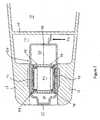
- FIG. 1the overall structure of a preferred embodiment of a personal communication device, here in the form of a hearing aid 10, is seen, having a housing 12 in which is mounted a hearing aid receiver or loudspeaker 20.
- the present inventionis able to reduce the overall dimensions of the system so that it is useful even in CIC, ITE, and ITC hearing aids.
- larger systems and dimensionsmay be provided, as may systems comprising multiple microphones/loudspeakers for increasing the volume or directional properties of the sound emission/detection.
- the housing 12has an inner space that is divided into first and second inner compartments 14 and 15, respectively.
- the first inner compartment 14is delimited by the housing walls 17 and an intermediate wall 16 providing an acoustic sealing between the compartments 14 and 15.
- the transducer element 20is mounted in the space 14 so as to close or seal an opening 18 in the housing 12.
- the transducer element 20is adapted to receive or generate sound and has a sound inlet/outlet 22 exposed to the surroundings of the hearing aid 10 in the sound inlet/outlet port or opening 18.
- the inner structure of the hearing aid receiver or transducer element 20will be described in further detail further below, primarily as a sound generator even though the present structure is also useful as a sound receiver.
- the receiver/transducer element 20comprises one or more acoustical apertures or openings 24, the operation of which will be described further below.
- the sound generation or reception of the transducer element 20is controlled or assisted using electronics 30 provided inside the housing 12 and which is electrically connected to the element 20 via electrical conductors 32 contacting solder bumps 34 on the element 20.
- the element 20comprises two diaphragms 42 and 44.
- the diaphragmshave a first side pointing away from each other and a second side facing each other.
- the volume or space between the outlet 22 and the diaphragms 42/44is denoted a front chamber 48, and the space on the other side of (between) the diaphragm(s) 42/44 is denoted the back chamber 50.
- the two diaphragms 42/44may have separate back chambers, as it is described in relation to Figures 3 and 4 , or share a single or common back chamber, as it is illustrated in Figure 2 .
- This systemmay be similar to that described in US2003/0048920 and may have the advantage that it is automatically vibration damped compared to single diaphragm systems.
- Soundis generated by the diaphragms 42/44 by a driver system illustrated by 46, which drives the diaphragms to generate sound.
- the driver systemmay be as that illustrated in the above US application. Other drive systems are well known in the art.
- the direction of the soundmay also be reversed so that sound is received by entering the inlet 22, exiting the diaphragms 42/44, which then drive the means 46 which now generates a voltage/current/frequency or the like and transmits it to the means 30 which will process the signal further.
- the common back chamber 50is sealed by the diaphragms 42/44 and walls 52 and 54 which support the diaphragms 42/44 in known manners.
- the front chamber 48when the element 20 is provided inside the space 14, is acoustically connected to the space 14 via the opening 46.
- the acoustic properties of the front chamber 48, and thereby of the hearing aid 10may be determined by the dimensions also of the openings 24, the number of and positions thereof, as well as the dimensions of the space 14.
- the size of the chamber 48may now be drastically reduced in that the space 14 is now also brought into use.
- FIG. 3Another embodiment is illustrated in Figure 3 , wherein the openings 24 are provided into the back chamber 50. Then, this affects the acoustic properties of the back chamber 50, the element 20, and therefore of the hearing aid 10.
- back chamber 50may be divided between the diaphragms 42/44 and each of the back chambers 50 may be connected to the space 14 via one or more openings 24.
- FIG 4illustrates yet another embodiment in which the front chamber 48 now extends between the diaphragms 42/44 which now have their first sides facing toward each other and their second sides facing away from each other.
- walls 52/54separate the front and back chambers 48/50.
- the hatched lineillustrates that the back chamber 50 may be divided in order to provide a separate back chamber for each diaphragm.
- the openings 24connect the back chamber to the space 14.
- the openingsmay equally well be provided so as to connect the space 14 with the front chamber 48.
- solder bumps 34have been replaced with the springs 32 in order to have these resilient means provided on the element 20.
- the mounting of the element 20 in the housing 12is provided by sliding or translating the element 20 through the opening 18 in such a manner that the element 20, optionally using a sealing element, blocks the opening 18.
- this blockingalso facilitates a fixing of the element 20 in the housing 12.
- the element 20has a circumferential shoulder 60 either adapted to the inner dimensions of the opening 18 or adapted to engage the opening 18 via a sealing member 62, such as an 0-ring or the like.
- a sealing member 62such as an 0-ring or the like.
- this shouldermay be adapted to enter a cut-out part 61 (see Figure 5 ) of the housing. This provides more surfaces and more space for providing the fixing means desired.
- This shouldermay have the means for fixing the element 20 in the space 14.
- Such meansmay be snap fixing means, a thread, key way, bayonet socket, or any other manner in which one element may be removably fixed on/with/in another.
- this manneris one with which the element 20 may be brought into engagement with and out of engagement with solely by operating or handling the housing 10 and element 20 from the outside thereof, such as using a translation or a rotation of one element in relation to the other.
- vibration damped element 20actually facilitates a hard mounting where no vibration damping is provided between the element 20 and the housing 12.
- This hard mountingmay be provided by suitable adhesive agents such as an epoxy based UV curable adhesive, or by welding.
- the shoulder 60may be dispensed with, as is seen in Figure 4 illustrating an element 20 without the shoulder 60.
- the opening 18 or the sealing means 62would then instead abut or engage the outer surface of the element 20.
- the fixing meanscould be provided also at other positions, such as at the sides of the element 20 or at the bottom thereof close to the wall 16,
- FIG. 6One alternative is seen in Figure 6 , wherein an external fixing member 64 is provided which is able to be releasably fixed to the housing 12.
- This fixing member 64is adapted to engage or abut the transducer/receiver 20 and force It toward the compartment 14, such as against the springs 32, in order to fix the receiver/transducer 20 in a predetermined position (such as defined by a cavity in the means 64) and in order to ensure the electrical connection between the means 32 and 34, if these are positioned as illustrated in Figure 1 .
- This means 64may also serve other purposes, such as provide a sealing member, such as a membrane, for preventing dirt, dust, wax etc. from entering the opening 22.
- the member 62may also simply provide a grating or guard preventing physical contact from the outside to the receiver/transducer 20.
- the means 64may be fixed in any of the above-mentioned manners in order for it to be releasably fixed to the housing 12.
- the sealing means 62may be provided after positioning of the element 20 in the space 14, so that the circumference of the element 20 need not be fully adapted to the inner circumference of the opening 18. Also, in that situation, the circumference of the element 20 need not be the largest at the position closest to the opening 18, when the element 20 is in position in the space 14. Thus, the solder bumps 34 may be positioned on the side of the element 20 as illustrated in Figures 2 and 3 , even If no shoulder 60 is present.
- the largest outer contour circumscribing the outer surface of the transducer elementwhen projected onto a plane perpendicular to the direction of introduction (see the fat arrow), is positioned at the position also abutting/engaging the opening 18 or the sealing means 62. In that manner, it is ensured that the element 20 is introducible through the opening 18 and that a sufficient sealing is obtainable.
- solder bumps 34 and the conductors 32provide an electrical connection using only abutment and no adhesion/welding/soldering/gluing or the like. In that manner, connection is automatically obtained when the element 20 is in the correct position and no additional steps are required.
- solder bumps 34 and the conductors 32are provided at the bottom of the space 14 at the opposite end of the element 20 than the opening 22.
- the element 20may be biased toward the conductors 32, which may themselves provide a spring action by e.g. forming a torsion spring, leaf spring, a resilient material or the like. This biasing may be provided by the hard mounting or vibration damping mounting or by other means.
- Figure 7illustrates another embodiment in which a transducer 20 is positioned in a housing 12 to form an assembly for a hearing aid 10.
- the transducer 20comprises two oppositely positioned membranes 42 and 44 driven by a driver 43 or which feed a detecting means 43 detecting movements of the membranes 42/44.
- the sound from the diaphragms 42/44may also be transported via openings radially (seen in the figure), if suitable openings or sound ports are provided in the housing 12.
- the transducer 20may extend slightly out of the housing 12 in order for the sound to exit in that direction.
- the transducer 20has, in addition to the back chambers defined on the "inner" sides of the diaphragms 42/44, a built-in common back chamber 50, which is connected to the second sides (facing each other and the means 43) of the membranes 42/44 via openings 45.
- the housing 12comprises, as does that of Fig. 1 , a first chamber 14 In which the transducer is positioned, and a second chamber 15, separated from the chamber 14 by a wall 16.
- electronicsamplifier or the like
- batteriesetc. may be positioned in the second chamber 15 in order to have as large a volume as possible in the first chamber 14.
- the transducer 20is fixed inside the housing 12 by two interlocking hooks 70, one of which is fixed to the wall 16 and one of which is fixed to the transducer 20. Introducing the transducer 20 through the opening in the housing 12 will make the hooks 70 engage and thereby fix the transducer 20 in the housing 12.
- fixing meansmay be used, and in general, it may be preferred that the fixing means are detachable in order to easily have these disengage In order to be able to remove the transducer 20 from the housing 12.
- the hooks 70may be used for providing electrical connection to the driving means 43, preferably comprising two coils in the present transducer 20.
- connection means as described in the other drawingsmay be used in order to obtain a solder-less or solder-free, electrical connection to the driving means or detecting means of the transducer.
- Fig. 7may be used equally well in all types of communication systems having a part for introduction into the ear of a person. It is not important from where the signal for a driver (to generate sound) or to where a signal (if sound is detected, is transmitted. Thus, this set-up is useful in both hearing aids, where the signal stems from a microphone) as well as in ear monitors, where the signal may be transmitted over a wireless connection from a remote source.
Landscapes
- Physics & Mathematics (AREA)
- Engineering & Computer Science (AREA)
- Acoustics & Sound (AREA)
- Signal Processing (AREA)
- General Health & Medical Sciences (AREA)
- Health & Medical Sciences (AREA)
- Neurosurgery (AREA)
- Otolaryngology (AREA)
- Electromagnetism (AREA)
- Telephone Set Structure (AREA)
- Audible-Bandwidth Dynamoelectric Transducers Other Than Pickups (AREA)
- Electrostatic, Electromagnetic, Magneto- Strictive, And Variable-Resistance Transducers (AREA)
- Details Of Audible-Bandwidth Transducers (AREA)
- Piezo-Electric Transducers For Audible Bands (AREA)
- Adornments (AREA)
Abstract
Description
- The present invention relates to improvements in personal communication devices, such as hearing aids or in ear monitors, and especially in miniature hearing aids or monitors, such as ITE/CIC/ITC hearing aids or monitors, which require extremely small components and which need to be adapted to the dimensions of the ear canal of the user.
- Hearing aid receivers or loudspeakers have conventionally been mounted in both BTE and ITE hearing aids with the use of resilient suspensions to suppress or attenuate mechanical vibrations of the receivers and prevent that these were transmitted to a microphone of the hearing aid. Due to the requirements of very large acoustical gain between proximately located microphone and receiver components, the utilisation of the resilient suspension has been required to avoid feedback oscillation caused by coupling of mechanical vibrations between the receiver and microphone.
- Conventional or prior art resilient suspensions include elastomeric rubber boots and elastomeric strips or ribbons mounted to partly or fully encircle the receiver housing and optionally were provided with shock absorbing protrusions and several other types of resilient supports. Through careful design of the resilient properties of these prior art resilient suspensions these have been adapted to attenuate or decouple mechanical vibrations of the receiver so as to prevent these from being coupled to the housings of the BTE and ITE hearing aids.
- Furthermore, electrical signals from a hearing aid amplifier to the receiver have conventionally been provided through for exampie a pair of flexible electrical leads such as multi-core litze wires soldered to respective terminals of the receiver.
- These prior art hearing aid constructions incurred a number of technical problems that are overcome by the present inventions.
- One problem associated with the above-mentioned hearing aid construction techniques is the space requirement inside the hearing aid shell to accommodate the resilient suspension and flexible leads. In small hearing aids such as the ITE type of hearing aids and in particular in ITC and CIC type of hearing aids, the available space for the resilient suspension at a tip of the hearing aid shell is typically very limited since the shell tip must be dimensioned for placement deeply inside the ear canal of the user or patient. Another problem is that even if adequate space for the resilient suspension Is available at the tip of the hearing aid shell, the correct placement of the resilient suspension can be very difficult and therefore time consuming for the assembly technician because it must be ensured that the resiliently suspended receiver is allowed substantially unrestricted vibration and is without contact to one of the walls of the hearing aid shell. Finally, the correct placement of the resiliently suspended receiver is subjected to additional difficulties by the presence of the pair of flexible electrical leads which tends to pull or push the receiver away from the correct position due to the stiffness of the leads and the low weight and resilient suspension of the receiver.
- These problems are firstly encountered during manufacture of the hearing aid but unfortunately resurface if the hearing aid receiver malfunctions or fails in the field and needs replacement in a service and repair shop. This is unfortunately a very common situation because the receiver is placed at a very exposed position deeply inside in the user's ear canal where it is subjected to moisture and cerumen contamination. In this latter repair situation, it may be an even more difficult task for the service technician to ensure correct positioning of the replacement receiver inside its resilient suspension and the shell part(s) because he may lack adequate instructions, measurement equipment or training to complete the task. Furthermore, in prior art of ITE hearing aids the receiver has only been replaceable from a rear portion or so-called faceplate portion of the aid where a substantially plane premanufactured plastic plate has been glued to the upper circumferential portion of the hearing aid shell so as to isolate the interior of the hearing aid from the surrounding environment. Accordingly, to replace the defective receiver, the faceplate portion of the aid had to be reopened with a substantial risk of damaging the customized ITE shell and/or mechanical or electronic components housed within the shell.
US 4,109,116 discloses a miniature dual-diaphragm moving armature receiver for hearing aid applications. The dual-diaphragm receiver is formed as a back-to-back mounted assembly of a pair of conventional single diaphragm moving armature receiver to achieve cancellation of mechanical vibrations of the receiver. The dual-diaphragm receiver is mounted inside an earphone and the earphone may be inserted into and acoustically coupled to an earmold that is insertable in the ear canal of a hearing aid user. The disclosed dual-diaphragm moving armature receiver does not comprise a common front chamber or a common back chamber but has separate chambers coupled exclusively to each single diaphragm receiver.WO 2004/049756 discloses a single diaphragm moving armature receiver that comprises a motion reversing arrangement or linkage assembly coupled between a diaphragm and the moving armature. If the effective moving masses of the armature assembly and the diaphragm assembly are made identical, some cancellation of mechanical vibrations of the receiver can be achieved.US2003/0048920 describes a receiver having two sound outputs for different frequency intervals. These outputs are derived from the front and back chamber, respectively, of the receiver and output from different outputs of a housing.- Other technologies may be seen in
US-A-6,549,634 6,813,364 , and6,891,956 ,EP 1257147 ,WO2004/103018 , andDE 35 02 178 . - Also, in general, the miniature loudspeaker may e.g. be based on a moving coil transducer technology or a moving armature transducer technology.
- A first aspect of the invention relates to a device according to claim 1.
- Thus, the below-mentioned advantages of the abutting/engaging electrical contact are obtained.
- In this context, a "miniature loudspeaker" or "miniature transducer" will be a loudspeaker/transducer having extend, in the plane of the diaphragm, over an area of less than 4.0x4.0 mm, such as 3.5x3.5 mm, or even more preferably less than 3.0x3.0 mm. Alternatively or additionally, a miniature loudspeaker/transducer comprises a so-called MEMS based transducer element which is a transducer element wholly or at least partly fabricated by application of Micro Mechanical System Technology. The miniature loudspeaker element may comprise a semiconductor material such as Silicon or Gallium Arsenide in combination with conductive and/or isolating materials such as silicon nitride, polycrystalline silicon, silicon oxide and glass. Alternatively, the miniature transducer element may comprise solely conductive materials such as aluminium, copper etc. optionally in combination with isolating material like glass and/or silicon oxide.
- The miniature transducer may be a sound producing miniature loudspeaker or a sound detecting receiver.
- According to this aspect of the present invention, hearing aids are normally divided into ITE/ITC/CIC hearing aids. Naturally, an in ear monitor may be denoted in the same manner and dimensioned in the same manner. Therefore, these denotations will be used for both types of apparatus. Such communication devices may be provided that could comprise a single- or dual-diaphragm receiver or loudspeaker that is replaceable through a front opening located at the tip of the communication device. As will be clear further below, an interesting assembly is related to a receiver assembly that comprises a lid with a sound outlet port and a wax guard or barrier disposed across the sound outlet port. The receiver assembly and the communication device with the tip replaceable receiver according to the present invention effectively solve a number of the previously-mentioned problems associated with service and repair replacements of a defective receiver.
- Naturally, the housing may have an inner space having the first compartment and another compartment acoustically separated from the first compartment.
- Preferably, the electrically conducting contact means of the first compartment are provided on a surface opposite to the sound outlet port, and the electrically conducting contact means of the miniature transducer are provided on an outer surface thereof substantially opposite to the sound outlet.
- In this manner, engagement is obtained forcing or biasing the miniature loudspeaker into the first chamber in a direction away from the outlet port. Naturally, however, these electrically conducting elements may be provided in other positions, whereby the biasing is then obtained along other directions.
- Also, as vibrations are normally not desired, the miniature transducer may comprise a pair of diaphragms, the first sides of which are oppositely directed. Then, the housing and miniature transducer may be mechanically coupled/attached to each other without a resilient suspension.
- Then, an embodiment is obtained being a dual-diaphragm miniature transducer for a communication device and which comprises a first and a second electrical biasing/engaging/abutting contact adapted to contact respective corresponding electrical pads placed on a suitable wall portion of the communication device shell. The dual-diaphragm miniature transducer with biasing/abutting/engaging contacts may be based on moving armature or moving coil operating principles. The vibration cancellation effect provided by the present dual-diaphragm miniature loudspeaker allows it to be hard-mounted directly in a communication device shell without the resilient suspension and the engaging/abutting/biasing contacts replace the conventional flexible electrical leads to simplify the communication device assembly process.
- Also, in order to facilitate assembly and disassembly, the housing and the miniature tranducer may comprise mating detachable fixing means adapted to position the miniature transducer in a predetermined position in the first compartment, the mating detachable fixing means being operable by engaging the housing and/or miniature tranducer from outside the housing and/or miniature loudspeaker.
- Thus, the fixing means could comprise one or more of a snap lock, a thread, a bayonet coupling, a key way, and snap taps.
- In addition, at least one of the first and second electrically conducting contact means could be adapted to provide a resilient electrically conducting contact means, where the other then may have any shape, such as a simple fixed surface or element which may protrude from or be depressed into a surface of the housing or miniature loudspeaker. Then, the resilient electrically conducting contact means comprises an electrically conducting spring (such as a helical, torsion, and/or leaf spring), or be an electrically conducting foam, web, or the like.
- Finally, in order to be able to use at least part of the first chamber for acoustic purposes, the miniature loudspeaker could comprise one or more diaphragms positioned in the miniature loudspeaker for producing the sound, each diaphragm having a first side and a second, opposite side, where an acoustic path/opening/tunnel/channel exists between the first side(s) and the sound outlet, the miniature loudspeaker further comprising an acoustic path/opening/tunnel/channel between the second side(s) of the diaphragm(s) and the at least substantially sealed first compartment of the housing.
- In this connection, "substantially sealed" is to be interpreted with the acoustic properties in mind. Thus, a small gas passage may be allowed in order to provide a DC passage of gas for pressure equalization when the atmospheric pressure of the surroundings of the communication device changes. Then, a biasing of the diaphragm would exist, if an equalization of the back chamber was not performed. This DC gas passage, however, is so small that it does not affect the acoustic properties of the chamber to any significant degree at audible frequencies.
- The same interpretation is made of the "acoustic path/opening/tunnel/channel" and the "acoustic coupling", which again are at audible frequencies. The path and coupling may be provided by an open channel or via e.g. a membrane, if that is desired. Again, the path and coupling may be adapted to provide predetermined acoustic properties - normally in the audible area.
- The first compartment may be acoustically connected to any of the front or back chamber of the miniature loudspeaker.
- In addition, the miniature transducer/loudspeaker might further comprise one or more of:
- a mounting ring for providing a sealing between the opening or sound inlet/outlet port and the miniature transducer/loudspeaker, the ring having predetermined dimensions,
- an element adapted to engage the housing at the sound inlet/outlet port or the opening and to bias the miniature transducer/loudspeaker inwardly into the first chamber, and
- a wax guard sealing provided between the opening or sound outlet port and the surroundings.
- The mounting ring may act to keep the miniature transducer/loudspeaker in place and may seal any gaps present between the miniature transducer/loudspeaker and the opening in the housing. This ring may be more easily operable and engageable than the miniature transducer/loudspeaker, whereby it is ensured that the miniature transducer/loudspeaker is not harmed during assembly/disassembly. In addition, the removal of the mounting ring may require destruction of the ring without harming the more expensive and sensitive miniature transducer/loudspeaker.
- The biasing could be a biasing against resilient means for providing electrical contact between the miniature transducer/loudspeaker and the first chamber. This biasing also will prevent the miniature transducer/loudspeaker from moving from a predetermined position.
- The wax guard may be provided on the outside of the housing at the sound inlet/outlet in order to prevent wax and dirt from entering the housing and miniature transducer/loudspeaker. This wax guard, which may be a membrane, preferably is removable and may be provided on the biasing means or the mounting ring In order to make attachment/assembly and disassembly faster and easier.
- In general, the housing could comprise cured photopolymer resin suitable for SLA formation of the housing. SLA (Stereo lithography Apparatus) is a rapid prototyping technology wherein a computer system receives data from a CAD model of the communication device shell contour and cures a liquid photopolymer resin with a laser beam to form a solid three-dimensional object. The rapid prototyping technology makes it cost-effective and straight-forward to build the closed acoustic chamber integrally with the communication device shell at the time of manufacture.
- In addition, the housing may be made as a single piece, which may especially be advantageous with the above-mentioned tip-mounting of the miniature transducer/loudspeaker.
- Also, the housing may be a customized ITE/ITC/CIC housing. These housings must have very small dimensions of the parts positioned in the ear canal of the user. The present invention facilitates the providing of very small communication devices.
- In addition, the housing may comprise the first compartment and a second compartment which are separated by a wall part comprising a plurality of through-going electrical conductors. Thus, the miniature transducer/loudspeaker could be positioned in the first compartment and the second compartment could comprise battery, amplifier, other miniature transducer/loudspeakers etc. Then, also, any electrical contacts and any fixing means could be attached to or integral with this wall part separating the two compartments.
- Finally, the housing could have outer dimensions adapted to the dimensions of an ear canal of a specific person and wherein inner dimensions of the first compartment are adapted to the person's hearing problems. This is due to the fact that miniature transducer/loudspeakers may be made so small that excess space is available when no resilient mounting is required of the miniature transducer/loudspeaker in the housing. This space may be used for acoustically adapting the communication device to the particular person and the particular hearing problems of that user.
- In a final aspect, the invention relates to a method of mounting a miniature transducer in a housing having a first compartment and an opening or sound inlet/outlet port thereof toward the surroundings of the housing, the method comprising the steps of:
- providing a miniature transducer having a sound inlet or outlet positioned in a predetermined area or part thereof,
- translating the miniature transducer through the opening and at least partly into the first compartment,
- providing electrical contact between electrically conducting means of the miniature transducer and electrically conducting means of the first compartment,
- fixing the miniature transducer in a releasable manner so that the opening and first compartment are at least substantially sealed and so that sound is able to enter or exit the sound inlet/outlet from or to the surroundings of the housing.
- This is the above-mentioned tip-mounting where the miniature transducer is provided in the housing at the position where the sound enters/exits the housing. The advantages of this aspect have been mentioned above.
- In one situation, the step of providing the miniature transducer comprises providing a miniature transducer comprising one or more diaphragms positioned in the miniature transducer for producing or receiving the sound, each diaphragm having a first side and a second, opposite side, where an acoustic path/opening/tunnel/channel exists between the first side(s) and the sound inlet/outlet,
the method further comprising the step of providing an acoustic path/opening/tunnel/channel between the second side(s) of the diaphragm(s) and the at least substantially sealed first compartment of the housing. - Then, the vibration reduction/damping may be obtained when the miniature transducer comprises at least two diaphragms, the first sides of which are oppositely directed. Then, the fixing step could comprise fixing the housing and the miniature transducer directly to each other, such as without resilient suspension.
- Also, the fixing step preferably comprises releasably fixing the miniature transducer in a predetermined position in the first compartment, the fixing step comprising engaging the housing and/or miniature transducer from outside the housing and/or miniature transducer. Then, the method could further comprise the step of detaching the fixed miniature transducer from the housing, the detaching step comprising operating or engaging the housing and/or the miniature transducer from outside the housing and/or the miniature transducer.
- The fixing step could comprise using one or more of a snap lock, a thread, a bayonet coupling, a key way, and snap taps.
- Preferably, the step of providing electrical contact comprises mating first electrically conducting contact means of the first compartment and second conducting contact means of the miniature transducer so as to provide solderless/solderfree, electrical conduction between the contact means of the first compartment and the miniature transducer. Thus, the mating step preferably comprises having at least one of the first and second electrically conducting contact means provide a resilient electrically conducting contact means. Such resilient electrically conducting contact means could comprise an electrically conducting spring (such as a helical, torsion, and/or leaf spring), a foam, a web or the like.
- In one preferred embodiment, the step of providing the housing comprises providing a housing having the first and a second compartment acoustically shielded from each other by a wall part. As mentioned above, the second compartment could be used for housing a battery, an amplifier, and/or other miniature transducers. Then, electrical contacts and fixing means may be attached to or integral with a wall part separating the first and second compartments.
- In the following, the invention will be described with reference to the drawings, wherein:
Fig. 1 illustrates an embodiment of a communication device with a receiver/transducer element therein,Fig. 2 illustrates a first embodiment of a receiver/transducer element,Fig. 3 illustrates a second embodiment of a receiver/transducer element,Fig. 4 illustrates a third embodiment of a receiver/transducer element,Fig. 5 illustrates a manner of fixing the receiver/transducer element to the housing,Fig. 6 illustrates the use of an external biasing element, andFig. 7 illustrates another embodiment using a particular type of transducer.- In
Figure 1 , the overall structure of a preferred embodiment of a personal communication device, here in the form of ahearing aid 10, is seen, having ahousing 12 in which is mounted a hearing aid receiver orloudspeaker 20. - The present invention is able to reduce the overall dimensions of the system so that it is useful even in CIC, ITE, and ITC hearing aids. Naturally, also larger systems and dimensions may be provided, as may systems comprising multiple microphones/loudspeakers for increasing the volume or directional properties of the sound emission/detection.
- The
housing 12 has an inner space that is divided into first and secondinner compartments inner compartment 14 is delimited by thehousing walls 17 and anintermediate wall 16 providing an acoustic sealing between thecompartments transducer element 20 is mounted in thespace 14 so as to close or seal anopening 18 in thehousing 12. - The
transducer element 20 is adapted to receive or generate sound and has a sound inlet/outlet 22 exposed to the surroundings of thehearing aid 10 in the sound inlet/outlet port oropening 18. - The inner structure of the hearing aid receiver or
transducer element 20 will be described in further detail further below, primarily as a sound generator even though the present structure is also useful as a sound receiver. - In addition to the
sound outlet 22, the receiver/transducer element 20 comprises one or more acoustical apertures oropenings 24, the operation of which will be described further below. - The sound generation or reception of the
transducer element 20 is controlled or assisted usingelectronics 30 provided inside thehousing 12 and which is electrically connected to theelement 20 viaelectrical conductors 32 contacting solder bumps 34 on theelement 20. - One embodiment of the inner structure of the
element 20 may be seen inFigure 2 , wherein theelement 20 comprises twodiaphragms outlet 22 and thediaphragms 42/44 is denoted afront chamber 48, and the space on the other side of (between) the diaphragm(s) 42/44 is denoted theback chamber 50. The twodiaphragms 42/44 may have separate back chambers, as it is described in relation toFigures 3 and 4 , or share a single or common back chamber, as it is illustrated inFigure 2 . - This system may be similar to that described in
US2003/0048920 and may have the advantage that it is automatically vibration damped compared to single diaphragm systems. - Sound is generated by the
diaphragms 42/44 by a driver system illustrated by 46, which drives the diaphragms to generate sound. The driver system may be as that illustrated in the above US application. Other drive systems are well known in the art. - It should be noted that the direction of the sound may also be reversed so that sound is received by entering the
inlet 22, exiting thediaphragms 42/44, which then drive themeans 46 which now generates a voltage/current/frequency or the like and transmits it to themeans 30 which will process the signal further. - The
common back chamber 50 is sealed by thediaphragms 42/44 andwalls diaphragms 42/44 in known manners. - In this embodiment, the
front chamber 48, when theelement 20 is provided inside thespace 14, is acoustically connected to thespace 14 via theopening 46. Thus, the acoustic properties of thefront chamber 48, and thereby of thehearing aid 10, may be determined by the dimensions also of theopenings 24, the number of and positions thereof, as well as the dimensions of thespace 14. In addition, the size of thechamber 48 may now be drastically reduced in that thespace 14 is now also brought into use. - Another embodiment is illustrated in
Figure 3 , wherein theopenings 24 are provided into theback chamber 50. Then, this affects the acoustic properties of theback chamber 50, theelement 20, and therefore of thehearing aid 10. - In
Figure 3 , it is also illustrated that theback chamber 50 may be divided between thediaphragms 42/44 and each of theback chambers 50 may be connected to thespace 14 via one ormore openings 24. Figure 4 illustrates yet another embodiment in which thefront chamber 48 now extends between thediaphragms 42/44 which now have their first sides facing toward each other and their second sides facing away from each other.- Again,
walls 52/54 separate the front andback chambers 48/50. Also, the hatched line illustrates that theback chamber 50 may be divided in order to provide a separate back chamber for each diaphragm. In this embodiment, theopenings 24 connect the back chamber to thespace 14. However, the openings may equally well be provided so as to connect thespace 14 with thefront chamber 48. - In this figure, however, the solder bumps 34 have been replaced with the
springs 32 in order to have these resilient means provided on theelement 20. - The mounting of the
element 20 in thehousing 12 is provided by sliding or translating theelement 20 through theopening 18 in such a manner that theelement 20, optionally using a sealing element, blocks theopening 18. Preferably, this blocking also facilitates a fixing of theelement 20 in thehousing 12. - Preferably, the
element 20 has acircumferential shoulder 60 either adapted to the inner dimensions of theopening 18 or adapted to engage theopening 18 via a sealingmember 62, such as an 0-ring or the like. - Alternatively, this shoulder may be adapted to enter a cut-out part 61 (see
Figure 5 ) of the housing. This provides more surfaces and more space for providing the fixing means desired. - This shoulder may have the means for fixing the
element 20 in thespace 14. Such means may be snap fixing means, a thread, key way, bayonet socket, or any other manner in which one element may be removably fixed on/with/in another. Preferably, this manner is one with which theelement 20 may be brought into engagement with and out of engagement with solely by operating or handling thehousing 10 andelement 20 from the outside thereof, such as using a translation or a rotation of one element in relation to the other. - The use of a vibration damped
element 20 actually facilitates a hard mounting where no vibration damping is provided between theelement 20 and thehousing 12. This hard mounting may be provided by suitable adhesive agents such as an epoxy based UV curable adhesive, or by welding. - The
shoulder 60 may be dispensed with, as is seen inFigure 4 illustrating anelement 20 without theshoulder 60. Theopening 18 or the sealing means 62 would then instead abut or engage the outer surface of theelement 20. - Naturally, the fixing means could be provided also at other positions, such as at the sides of the
element 20 or at the bottom thereof close to thewall 16, - One alternative is seen in
Figure 6 , wherein anexternal fixing member 64 is provided which is able to be releasably fixed to thehousing 12. This fixingmember 64 is adapted to engage or abut the transducer/receiver 20 and force It toward thecompartment 14, such as against thesprings 32, in order to fix the receiver/transducer 20 in a predetermined position (such as defined by a cavity in the means 64) and in order to ensure the electrical connection between themeans Figure 1 . - This means 64 may also serve other purposes, such as provide a sealing member, such as a membrane, for preventing dirt, dust, wax etc. from entering the
opening 22. Themember 62 may also simply provide a grating or guard preventing physical contact from the outside to the receiver/transducer 20. - Naturally, the
means 64 may be fixed in any of the above-mentioned manners in order for it to be releasably fixed to thehousing 12. - The sealing means 62 may be provided after positioning of the
element 20 in thespace 14, so that the circumference of theelement 20 need not be fully adapted to the inner circumference of theopening 18. Also, in that situation, the circumference of theelement 20 need not be the largest at the position closest to theopening 18, when theelement 20 is in position in thespace 14. Thus, the solder bumps 34 may be positioned on the side of theelement 20 as illustrated inFigures 2 and 3 , even If noshoulder 60 is present. - However, it is preferred that the largest outer contour circumscribing the outer surface of the transducer element, when projected onto a plane perpendicular to the direction of introduction (see the fat arrow), is positioned at the position also abutting/engaging the
opening 18 or the sealing means 62. In that manner, it is ensured that theelement 20 is introducible through theopening 18 and that a sufficient sealing is obtainable. - The solder bumps 34 and the
conductors 32 provide an electrical connection using only abutment and no adhesion/welding/soldering/gluing or the like. In that manner, connection is automatically obtained when theelement 20 is in the correct position and no additional steps are required. - Different positions are possible for the solder bumps 34 and the
conductors 32. InFigures 1 and 4 , these elements are provided at the bottom of thespace 14 at the opposite end of theelement 20 than theopening 22. In that manner, theelement 20 may be biased toward theconductors 32, which may themselves provide a spring action by e.g. forming a torsion spring, leaf spring, a resilient material or the like. This biasing may be provided by the hard mounting or vibration damping mounting or by other means. - Other positions may be at sides of the
element 20, but the biasing effect may be the same. - Naturally, other manners of providing the pressure contacts or abutting contacts may be used, such as electrically conducting areas of the surface of the
element 20 replacing solder bumps. The resilient parts may be provided on theelement 20 Instead in thehousing 12. Figure 7 illustrates another embodiment in which atransducer 20 is positioned in ahousing 12 to form an assembly for ahearing aid 10.- The
transducer 20 comprises two oppositely positionedmembranes driver 43 or which feed a detectingmeans 43 detecting movements of themembranes 42/44. Side facing openings 49 are provided between the first (outer) sides of themembranes 42/44, where also small front chambers are defined, and a common, or second,front chamber 48 of the transducer. The sound inlet/output 22 of thetransducer 20 being directly connected to thecommon front chamber 48.- Naturally, the sound from the
diaphragms 42/44 may also be transported via openings radially (seen in the figure), if suitable openings or sound ports are provided in thehousing 12. Alternatively, thetransducer 20 may extend slightly out of thehousing 12 in order for the sound to exit in that direction. - The
transducer 20 has, in addition to the back chambers defined on the "inner" sides of thediaphragms 42/44, a built-incommon back chamber 50, which is connected to the second sides (facing each other and the means 43) of themembranes 42/44 viaopenings 45. - The
housing 12 comprises, as does that ofFig. 1 , afirst chamber 14 In which the transducer is positioned, and asecond chamber 15, separated from thechamber 14 by awall 16. As mentioned, electronics (amplifier or the like) and batteries, etc. may be positioned in thesecond chamber 15 in order to have as large a volume as possible in thefirst chamber 14. - In the present embodiment, the
transducer 20 is fixed inside thehousing 12 by two interlocking hooks 70, one of which is fixed to thewall 16 and one of which is fixed to thetransducer 20. Introducing thetransducer 20 through the opening in thehousing 12 will make thehooks 70 engage and thereby fix thetransducer 20 in thehousing 12. - Naturally, other fixing means may be used, and in general, it may be preferred that the fixing means are detachable in order to easily have these disengage In order to be able to remove the
transducer 20 from thehousing 12. - In addition or alternatively, the
hooks 70 may be used for providing electrical connection to the driving means 43, preferably comprising two coils in thepresent transducer 20. Alternatively, connection means as described in the other drawings may be used in order to obtain a solder-less or solder-free, electrical connection to the driving means or detecting means of the transducer. - It should be noted that the set-up of
Fig. 7 may be used equally well in all types of communication systems having a part for introduction into the ear of a person. It is not important from where the signal for a driver (to generate sound) or to where a signal (if sound is detected, is transmitted. Thus, this set-up is useful in both hearing aids, where the signal stems from a microphone) as well as in ear monitors, where the signal may be transmitted over a wireless connection from a remote source.
Claims (21)
- A personal communication device comprising a housing and a miniature loudspeaker, wherein:- the housing has a first compartment and a sound outlet port toward the surroundings of the housing,- the miniature loudspeaker is removably receivable in the first compartment so that the sound outlet port is at least substantially sealed around a predetermined portion of the miniature loudspeaker,- the miniature loudspeaker comprises a sound outlet acoustically coupled to the sound outlet port, and- the first compartment and the miniature loudspeaker comprise mating first and second electrically conducting contact means adapted to provide solderless/solderfree, electrical conduction between the contact means of the first compartment and the miniature loudspeaker,characterized in that the sound outlet port has a predetermined inner contour in a predetermined plane, and the miniature loudspeaker has an outer contour, in a plane perpendicular to an axis of the miniature loudspeaker through the miniature loudspeaker and the sound outlet thereof, and over a majority of its length from a position farthest from the outlet and toward the outlet, which outer contour may be circumscribed by the inner contour of the sound outlet port.
- A personal communication device according to claim 1, wherein the electrically conducting contact means of the first compartment are provided on a surface opposite to the sound outlet and wherein the electrically conducting contact means of the miniature loudspeaker are provided on an outer surface thereof substantially opposite to the sound outlet.
- A personal communication device according to claim 1 or 2, wherein the miniature loudspeaker comprises a pair of diaphragms, the first sides of which are oppositely directed.
- A personal communication device according to claim 3, wherein the housing and miniature loudspeaker are mechanically coupled without a resilient suspension.
- A personal communication device according to any of claims 1-4, wherein the housing and the miniature loudspeaker comprise mating detachable fixing means adapted to position the miniature loudspeaker in a predetermined position in the first compartment, the mating detachable fixing means being operable by engaging the housing and/or miniature loudspeaker from outside the housing and/or miniatures loudspeaker
- A personal communication device according to claim 5, wherein the fixing means comprise one or more of a snap lock, a thread, a bayonet coupling, a key way, and snap taps.
- A personal communication device according to any of claims 1-6, wherein at least one of the first and second electrically conducting contact means are adapted to provide a resilient electrically conducting contact means.
- A personal communication device according to claim 7, wherein the resilient electrically conducting contact means comprises an electrically conducting spring.
- A personal communication device according to any of claims 1-8, wherein the miniature loudspeaker comprises one or more diaphragms positioned in the miniature loudspeaker producing sound, each diaphragm having a first side and a second, opposite side, where an acoustic path/opening/tunnel/channel exists between the first side(s) and the sound outlet, the miniature loudspeaker further comprising an acoustic path/opening/tunnel/channel between the second side(s) of the diaphragm(s) and the at least substantially sealed first compartment of the housing.
- A personal communication device according to any of claims 1-9, which is a hearing aid or an in ear monitor.
- A personal communication device according to any of claims 1-10, wherein the miniature loudspeaker is a moving coil transducer or a moving armature transducer.
- A personal communication device according to any of claims 1-11, wherein the sound outlet of the miniature transducer is positioned in the predetermined portion.
- A method of mounting a miniature transducer in a housing of a personal communication device, the housing having a first compartment with an opening or sound inlet/outlet port toward the surroundings, the method comprising the steps of:- providing a miniature transducer having a sound inlet or outlet positioned in a predetermined area or part thereof,- translating the miniature transducer through the opening and at least partly into the first compartment,- providing electrical contact between electrically conducting means of the miniature transducer and electrically conducting means of the first compartment,- fixing the miniature transducer in a releasable manner so that the opening and first compartment are at least substantially sealed and so that sound is able to enter or exit the sound inlet/outlet from or to the surroundings of the housing.
- method according to claim 13, wherein the step of providing the miniature transducer comprises providing a miniature transducer comprising one or more diaphragms positioned in the miniature transducer for producing or receiving the sound, each diaphragm having a first side and a second, opposite side, where an acoustic path/opening/tunnel/channel exists between the first side(s) and the sound inlet/outlet,
the method further comprising the step of providing an acoustic path/opening/tunnel/channel between the second side(s) of the diaphragm(s) and the at least substantially sealed first compartment of the housing. - A method according to claim 14, wherein the miniature transducer comprises at least two diaphragms, the first sides of which are oppositely directed.
- A method according to claim 15, wherein the fixing step comprises fixing the housing and the miniature transducer directly to each other, such as without resilient suspension.
- A method according to claim any of claims 13-16, wherein the fixing step comprises releasably fixing the miniature transducer in a predetermined position in the first compartment, the fixing step comprising engaging the housing and/or miniature transducer from outside the housing and/or miniature transducer.
- A method according to any of claims 13-17, wherein the fixing step comprises using one or more of a snap lock, a thread, a bayonet coupling, a key way, and snap taps.
- A method according to any of claims 13-18, wherein the step of providing electrical contact comprises mating first electrically conducting contact means of the first compartment and second conducting contact means of the miniature transducer so as to provide solderless/solderfree, electrical conduction between the contact means of the first compartment and the miniature transducer.
- A method according to any of claims 13-17, wherein the step of providing the housing comprises providing a housing having the first and a second compartment acoustically shielded from each other by a wall part.
- A method of handling a miniature transducer, the method comprising mounting the miniature transducer in the housing according to claim 17, the method further comprising the step of detaching the fixed miniature transducer from the housing, the detaching step comprising operating or engaging the housing and/or the miniature transducer from outside the housing and/or the miniature transducer.
Priority Applications (2)
| Application Number | Priority Date | Filing Date | Title |
|---|---|---|---|
| EP07114753AEP1853091B9 (en) | 2005-01-10 | 2006-01-09 | Hearing aid with miniature loudspeaker |
| DK07114753.2TDK1853091T3 (en) | 2005-01-10 | 2006-01-09 | Hearing aid with miniature speaker |
Applications Claiming Priority (1)
| Application Number | Priority Date | Filing Date | Title |
|---|---|---|---|
| US64264105P | 2005-01-10 | 2005-01-10 |
Related Child Applications (2)
| Application Number | Title | Priority Date | Filing Date |
|---|---|---|---|
| EP07114753ADivisionEP1853091B9 (en) | 2005-01-10 | 2006-01-09 | Hearing aid with miniature loudspeaker |
| EP07114753.2Division-Into | 2007-08-22 |
Publications (3)
| Publication Number | Publication Date |
|---|---|
| EP1684544A2 EP1684544A2 (en) | 2006-07-26 |
| EP1684544A3 EP1684544A3 (en) | 2006-08-23 |
| EP1684544B1true EP1684544B1 (en) | 2011-03-16 |
Family
ID=35457526
Family Applications (2)
| Application Number | Title | Priority Date | Filing Date |
|---|---|---|---|
| EP06000287ANot-in-forceEP1684544B1 (en) | 2005-01-10 | 2006-01-09 | Eletroacoustic transducer mounting in shells of personal communication devices |
| EP07114753ANot-in-forceEP1853091B9 (en) | 2005-01-10 | 2006-01-09 | Hearing aid with miniature loudspeaker |
Family Applications After (1)
| Application Number | Title | Priority Date | Filing Date |
|---|---|---|---|
| EP07114753ANot-in-forceEP1853091B9 (en) | 2005-01-10 | 2006-01-09 | Hearing aid with miniature loudspeaker |
Country Status (6)
| Country | Link |
|---|---|
| US (1) | US7822218B2 (en) |
| EP (2) | EP1684544B1 (en) |
| CN (1) | CN1838834B (en) |
| AT (2) | ATE515897T1 (en) |
| DE (1) | DE602006020645D1 (en) |
| DK (2) | DK1853091T3 (en) |
Families Citing this family (101)
| Publication number | Priority date | Publication date | Assignee | Title |
|---|---|---|---|---|
| DE102007023055A1 (en) | 2007-05-16 | 2008-11-27 | Siemens Medical Instruments Pte. Ltd. | Earpiece for a hearing aid with bayonet lock |
| WO2009023738A2 (en)* | 2007-08-14 | 2009-02-19 | Insound Medical, Inc. | Combined microphone and receiver assembly for extended wear canal hearing devices |
| US8135163B2 (en)* | 2007-08-30 | 2012-03-13 | Klipsch Group, Inc. | Balanced armature with acoustic low pass filter |
| US8160290B2 (en) | 2007-09-04 | 2012-04-17 | Sonion A/S | Electroacoustic transducer having a slotted terminal structure for connection to a flexible wire, and an assembly of the same |
| US8238596B2 (en)* | 2007-12-10 | 2012-08-07 | Klipsch Group, Inc. | In-ear headphones |
| US20090296971A1 (en)* | 2008-05-29 | 2009-12-03 | Siemens Hearing Instruments, Inc. | Hearing Instrument Receiver With Improved Low-Frequency Efficiency |
| US8774435B2 (en)* | 2008-07-23 | 2014-07-08 | Asius Technologies, Llc | Audio device, system and method |
| DE102008038213B8 (en)* | 2008-08-18 | 2010-02-11 | Siemens Medical Instruments Pte. Ltd. | Hearing aid with a transformer protection device |
| DE102009008376A1 (en)* | 2009-02-11 | 2010-08-12 | Sennheiser Electronic Gmbh & Co. Kg | receiver |
| WO2010151492A1 (en) | 2009-06-22 | 2010-12-29 | Shure Acquisition Holdings, Inc. | Earphone sleeve assembly having integral barrier |
| EP2285136B1 (en)* | 2009-07-15 | 2015-10-14 | Siemens Medical Instruments Pte. Ltd. | Hearing aid with replaceable earpiece |
| EP2293600B1 (en)* | 2009-07-27 | 2017-04-26 | Sivantos Pte. Ltd. | A processing unit and a receiving unit for a hearing aid device and a hearing aid device |
| WO2012006383A1 (en)* | 2010-07-08 | 2012-01-12 | Siemens Hearing Instruments, Inc. | Receiver pocket for an in-the-ear hearing instrument |
| US8538061B2 (en) | 2010-07-09 | 2013-09-17 | Shure Acquisition Holdings, Inc. | Earphone driver and method of manufacture |
| US8549733B2 (en)* | 2010-07-09 | 2013-10-08 | Shure Acquisition Holdings, Inc. | Method of forming a transducer assembly |
| US8548186B2 (en)* | 2010-07-09 | 2013-10-01 | Shure Acquisition Holdings, Inc. | Earphone assembly |
| US8712084B2 (en) | 2010-12-07 | 2014-04-29 | Sonion Nederland Bv | Motor assembly |
| US20120161258A1 (en)* | 2010-12-28 | 2012-06-28 | Loeppert Peter V | Package with a cmos die positioned underneath a mems die |
| WO2012103935A1 (en) | 2011-02-01 | 2012-08-09 | Phonak Ag | Hearing device with a receiver module and method for manufacturing a receiver module |
| WO2013004623A1 (en) | 2011-07-07 | 2013-01-10 | Sonion Nederland Bv | A multiple receiver assembly and a method for assembly thereof |
| NL2007136C2 (en) | 2011-07-18 | 2013-01-21 | Exsilent Res Bv | LISTENING SUPPORT DEVICE, IN PARTICULAR A HEARING DEVICE, AND A COMPRESSIBLE HOSE FOR USE THEREOF. |
| WO2013050183A1 (en)* | 2011-10-05 | 2013-04-11 | Siemens Medical Instruments Pte. Ltd. | A hearing instrument adapted to hold an exchangeable receiver into the housing and a method for making the hearing instrument |
| US8761423B2 (en) | 2011-11-23 | 2014-06-24 | Insound Medical, Inc. | Canal hearing devices and batteries for use with same |
| US8682016B2 (en) | 2011-11-23 | 2014-03-25 | Insound Medical, Inc. | Canal hearing devices and batteries for use with same |
| WO2013091724A1 (en)* | 2011-12-23 | 2013-06-27 | Phonak Ag | Tip-plate assembly, hearing device with a tip-plate assembly and method of manufacturing a hearing device with a tip-plate assembly |
| DK2654322T3 (en)* | 2012-04-20 | 2016-12-05 | Sivantos Pte Ltd | A hearing instrument with the sound tube connector |
| EP2723098B1 (en) | 2012-10-18 | 2016-12-14 | Sonion Nederland B.V. | A dual transducer with shared diaphragm |
| US9247359B2 (en) | 2012-10-18 | 2016-01-26 | Sonion Nederland Bv | Transducer, a hearing aid comprising the transducer and a method of operating the transducer |
| US8942399B2 (en) | 2012-11-19 | 2015-01-27 | Starkey Laboratories, Inc. | Methods for wideband receiver and module for a hearing assistance device |
| DK2747459T3 (en) | 2012-12-21 | 2018-12-17 | Sonion Nederland Bv | RIC unit with Thuras tube |
| EP2750413B1 (en) | 2012-12-28 | 2017-02-22 | Sonion Nederland B.V. | Hearing aid device |
| US9401575B2 (en) | 2013-05-29 | 2016-07-26 | Sonion Nederland Bv | Method of assembling a transducer assembly |
| TWI558224B (en)* | 2013-09-13 | 2016-11-11 | 宏碁股份有限公司 | Microphone module and electronic device |
| DK2849463T3 (en)* | 2013-09-16 | 2018-06-25 | Sonion Nederland Bv | Transducer with moisture transporting element |
| DK3550852T3 (en) | 2014-02-14 | 2021-02-01 | Sonion Nederland Bv | A joiner for a receiver assembly |
| DK2908559T3 (en) | 2014-02-18 | 2017-01-16 | Sonion As | Process for manufacturing devices for hearing aids |
| DK2914018T3 (en) | 2014-02-26 | 2017-01-30 | Sonion Nederland Bv | Speaker, luminaire and method |
| US9432774B2 (en) | 2014-04-02 | 2016-08-30 | Sonion Nederland B.V. | Transducer with a bent armature |
| US9578430B2 (en) | 2014-04-10 | 2017-02-21 | Gn Hearing A/S | Hearing aid |
| US9386383B2 (en) | 2014-04-10 | 2016-07-05 | Gn Resound A/S | Hearing aid receiver and a hearing aid comprising such a receiver |
| DK201470199A1 (en)* | 2014-04-10 | 2015-10-26 | Gn Resound As | A hearing aid with replacable receiver |
| US9392385B2 (en) | 2014-04-10 | 2016-07-12 | Gn Resound A/S | Hearing aid |
| EP2953380A1 (en) | 2014-06-04 | 2015-12-09 | Sonion Nederland B.V. | Acoustical crosstalk compensation |
| DK3041263T3 (en) | 2014-12-30 | 2022-04-11 | Sonion Nederland Bv | Hybrid receiver module |
| EP3051841B1 (en) | 2015-01-30 | 2020-10-07 | Sonion Nederland B.V. | A receiver having a suspended motor assembly |
| DK3057339T3 (en) | 2015-02-10 | 2021-01-04 | Sonion Nederland Bv | Microphone module with common middle audio input device |
| US9980029B2 (en) | 2015-03-25 | 2018-05-22 | Sonion Nederland B.V. | Receiver-in-canal assembly comprising a diaphragm and a cable connection |
| EP3073764B1 (en) | 2015-03-25 | 2021-04-21 | Sonion Nederland B.V. | A hearing aid comprising an insert member |
| DK3133829T3 (en)* | 2015-08-19 | 2020-06-22 | Sonion Nederland Bv | AUDIO UNIT WITH IMPROVED FREQUENCY RESPONSE |
| EP3139627B1 (en) | 2015-09-02 | 2019-02-13 | Sonion Nederland B.V. | Ear phone with multi-way speakers |
| US9668065B2 (en) | 2015-09-18 | 2017-05-30 | Sonion Nederland B.V. | Acoustical module with acoustical filter |
| EP3157270B1 (en) | 2015-10-14 | 2021-03-31 | Sonion Nederland B.V. | Hearing device with vibration sensitive transducer |
| DK3160157T3 (en) | 2015-10-21 | 2018-12-17 | Sonion Nederland Bv | Vibration-compensated vibroacoustic device |
| US10582303B2 (en) | 2015-12-04 | 2020-03-03 | Sonion Nederland B.V. | Balanced armature receiver with bi-stable balanced armature |
| EP3185584B1 (en) | 2015-12-21 | 2020-04-22 | Sonion Nederland B.V. | Receiver assembly having a distinct longitudinal direction |
| DK3197046T3 (en) | 2016-01-25 | 2021-07-05 | Sonion Nederland Bv | Self-biased output booster amplifier as well as its use |
| US10687148B2 (en) | 2016-01-28 | 2020-06-16 | Sonion Nederland B.V. | Assembly comprising an electrostatic sound generator and a transformer |
| EP3232685B1 (en) | 2016-04-13 | 2021-03-03 | Sonion Nederland B.V. | A dome for a personal audio device |
| EP3252444B1 (en) | 2016-06-01 | 2023-12-20 | Sonion Nederland B.V. | Vibration or acceleration sensor applying squeeze film damping |
| EP3279621B2 (en) | 2016-08-26 | 2025-04-09 | Sonion Nederland B.V. | Vibration sensor with low-frequency roll-off response curve |
| EP3293985B1 (en) | 2016-09-12 | 2021-03-24 | Sonion Nederland B.V. | Receiver with integrated membrane movement detection |
| DK3313097T3 (en) | 2016-10-19 | 2020-10-19 | Sonion Nederland Bv | AN EAR BUD OR DOME |
| EP3324649A1 (en) | 2016-11-18 | 2018-05-23 | Sonion Nederland B.V. | A transducer with a high sensitivity |
| EP3324538A1 (en) | 2016-11-18 | 2018-05-23 | Sonion Nederland B.V. | A sensing circuit comprising an amplifying circuit |
| US20180145643A1 (en) | 2016-11-18 | 2018-05-24 | Sonion Nederland B.V. | Circuit for providing a high and a low impedance and a system comprising the circuit |
| US10327072B2 (en) | 2016-11-18 | 2019-06-18 | Sonion Nederland B.V. | Phase correcting system and a phase correctable transducer system |
| EP3337184B1 (en) | 2016-12-14 | 2020-03-25 | Sonion Nederland B.V. | An armature and a transducer comprising the armature |
| US10405085B2 (en) | 2016-12-16 | 2019-09-03 | Sonion Nederland B.V. | Receiver assembly |
| EP3337191B1 (en) | 2016-12-16 | 2021-05-19 | Sonion Nederland B.V. | A receiver assembly |
| US10699833B2 (en) | 2016-12-28 | 2020-06-30 | Sonion Nederland B.V. | Magnet assembly |
| EP3702322A1 (en) | 2016-12-30 | 2020-09-02 | Sonion Nederland B.V. | Micro-electromechanical transducer |
| US10477308B2 (en) | 2016-12-30 | 2019-11-12 | Sonion Nederland B.V. | Circuit and a receiver comprising the circuit |
| EP3407625B1 (en) | 2017-05-26 | 2021-05-05 | Sonion Nederland B.V. | Receiver with venting opening |
| DK3407626T3 (en) | 2017-05-26 | 2020-07-27 | Sonion Nederland Bv | A receiver assembly comprising an armature and a diaphragm |
| DE102017114008A1 (en) | 2017-06-23 | 2018-12-27 | USound GmbH | In-ear listener |
| DK3429231T3 (en) | 2017-07-13 | 2023-04-11 | Sonion Nederland Bv | Hearing device including vibration prevention device |
| US10820104B2 (en) | 2017-08-31 | 2020-10-27 | Sonion Nederland B.V. | Diaphragm, a sound generator, a hearing device and a method |
| DK3451688T3 (en) | 2017-09-04 | 2021-06-21 | Sonion Nederland Bv | SOUND GENERATOR, SCREEN AND SPOUT |
| GB201714956D0 (en) | 2017-09-18 | 2017-11-01 | Sonova Ag | Hearing device with adjustable venting |
| DK3471437T3 (en) | 2017-10-16 | 2021-02-15 | Sonion Nederland Bv | A valve, a transducer comprising a valve, a hearing device and a method |
| CN109672963B (en) | 2017-10-16 | 2021-04-30 | 声扬荷兰有限公司 | Acoustic channel element with valve and transducer with acoustic channel element |
| CN109672967B (en) | 2017-10-16 | 2021-09-17 | 声扬荷兰有限公司 | Personal hearing device |
| DK3567873T3 (en) | 2018-02-06 | 2021-11-15 | Sonion Nederland Bv | Method for controlling an acoustic valve of a hearing device |
| DK3531720T3 (en) | 2018-02-26 | 2021-11-15 | Sonion Nederland Bv | Arranging a sounder and a microphone |
| DK3531713T3 (en) | 2018-02-26 | 2023-02-06 | Sonion Nederland Bv | Miniature Speaker with Acoustical Mass |
| US10567892B2 (en)* | 2018-03-09 | 2020-02-18 | Otican A/S | Speaker unit for a hearing aid device system, and hearing aid device system |
| EP3467457B1 (en) | 2018-04-30 | 2022-07-20 | Sonion Nederland B.V. | Vibration sensor |
| DK3579578T3 (en) | 2018-06-07 | 2022-05-02 | Sonion Nederland Bv | MINIATURE ANNOUNCER |
| US10951169B2 (en) | 2018-07-20 | 2021-03-16 | Sonion Nederland B.V. | Amplifier comprising two parallel coupled amplifier units |
| US11564580B2 (en) | 2018-09-19 | 2023-01-31 | Sonion Nederland B.V. | Housing comprising a sensor |
| EP3672277B1 (en) | 2018-12-19 | 2024-04-03 | Sonion Nederland B.V. | Miniature speaker with multiple sound cavities |
| US11190880B2 (en) | 2018-12-28 | 2021-11-30 | Sonion Nederland B.V. | Diaphragm assembly, a transducer, a microphone, and a method of manufacture |
| EP3675522A1 (en) | 2018-12-28 | 2020-07-01 | Sonion Nederland B.V. | Miniature speaker with essentially no acoustical leakage |
| US11533573B2 (en)* | 2018-12-31 | 2022-12-20 | Knowles Electronics, Llc | Receiver housing with integrated sensors for hearing device |
| DK3726855T3 (en) | 2019-04-15 | 2021-11-15 | Sonion Nederland Bv | A personal hearing device with a vent channel and acoustic separation |
| CN110267180B (en)* | 2019-07-26 | 2020-10-20 | 维沃移动通信(杭州)有限公司 | Electronic device |
| EP3806494B1 (en) | 2019-10-07 | 2023-12-27 | Sonion Nederland B.V. | Hearing device including an optical sensor |
| US11523204B2 (en) | 2021-03-19 | 2022-12-06 | Iyo Inc. | Ear-mountable listening device with multiple transducers |
| US12138075B2 (en) | 2022-11-07 | 2024-11-12 | Knowles Electronics, Llc | Ear-worn hearing device |
| WO2024133234A1 (en)* | 2022-12-23 | 2024-06-27 | Widex A/S | Microphone comprising an outer housing |
| EP4456551A1 (en)* | 2023-04-24 | 2024-10-30 | GN Audio A/S | A hearing device comprising a partition |
Family Cites Families (10)
| Publication number | Priority date | Publication date | Assignee | Title |
|---|---|---|---|---|
| US3048920A (en) | 1959-07-09 | 1962-08-14 | Charles J Wheeler | Tool for parting elongated fracturable members |
| US4109116A (en) | 1977-07-19 | 1978-08-22 | Victoreen John A | Hearing aid receiver with plural transducers |
| CH664057A5 (en)* | 1984-02-27 | 1988-01-29 | Phonak Ag | HOERGERAET. |
| CA1221315A (en)* | 1984-10-19 | 1987-05-05 | William J. Gastmeier | Hearing aid wax guard |
| WO2000079835A1 (en)* | 1999-06-16 | 2000-12-28 | Phonak Ag | Hearing-aid, worn behind the ear |
| DE60202397T2 (en)* | 2001-05-08 | 2005-06-16 | Matsushita Electric Industrial Co., Ltd., Kadoma | Speaker and mobile terminal |
| US6931140B2 (en)* | 2001-09-11 | 2005-08-16 | Sonionkirk A/S | Electro-acoustic transducer with two diaphragms |
| DE10214189B4 (en) | 2002-03-28 | 2004-04-22 | Siemens Audiologische Technik Gmbh | Device for sonicating an eardrum with a cerumen protection device and hearing aid |
| WO2004049757A1 (en) | 2002-11-22 | 2004-06-10 | Knowles Electronics, Llc | An apparatus for energy transfer in a balanced receiver assembly and manufacturing method thereof |
| PL1627550T3 (en) | 2003-05-09 | 2010-04-30 | Knowles Electronics Llc | Apparatus and method for generating acoustic energy in a receiver assembly |
- 2006
- 2006-01-09EPEP06000287Apatent/EP1684544B1/ennot_activeNot-in-force
- 2006-01-09ATAT07114753Tpatent/ATE515897T1/ennot_activeIP Right Cessation
- 2006-01-09DKDK07114753.2Tpatent/DK1853091T3/enactive
- 2006-01-09DKDK06000287.0Tpatent/DK1684544T3/enactive
- 2006-01-09EPEP07114753Apatent/EP1853091B9/ennot_activeNot-in-force
- 2006-01-09DEDE602006020645Tpatent/DE602006020645D1/enactiveActive
- 2006-01-09ATAT06000287Tpatent/ATE502491T1/ennot_activeIP Right Cessation
- 2006-01-10CNCN2006100774099Apatent/CN1838834B/ennot_activeExpired - Fee Related
- 2006-01-10USUS11/328,569patent/US7822218B2/ennot_activeExpired - Fee Related
Also Published As
| Publication number | Publication date |
|---|---|
| US7822218B2 (en) | 2010-10-26 |
| DK1684544T3 (en) | 2011-06-14 |
| EP1684544A3 (en) | 2006-08-23 |
| EP1853091B9 (en) | 2012-02-15 |
| DK1853091T3 (en) | 2011-10-24 |
| EP1684544A2 (en) | 2006-07-26 |
| ATE515897T1 (en) | 2011-07-15 |
| CN1838834A (en) | 2006-09-27 |
| DE602006020645D1 (en) | 2011-04-28 |
| EP1853091A1 (en) | 2007-11-07 |
| US20060153418A1 (en) | 2006-07-13 |
| EP1853091B1 (en) | 2011-07-06 |
| ATE502491T1 (en) | 2011-04-15 |
| CN1838834B (en) | 2012-12-05 |
Similar Documents
| Publication | Publication Date | Title |
|---|---|---|
| EP1684544B1 (en) | Eletroacoustic transducer mounting in shells of personal communication devices | |
| EP2134107B1 (en) | Method of operating a hearing instrument with improved venting | |
| US6205227B1 (en) | Peritympanic hearing instrument | |
| EP0548580B1 (en) | Non-occludable transducer for in-the-ear applications | |
| EP0520153B1 (en) | Hermetically sealed implantable transducer | |
| KR101829419B1 (en) | Earphone assembly | |
| EP1681904B1 (en) | Hearing instrument | |
| US7869610B2 (en) | Balanced armature bone conduction shaker | |
| CN212137926U (en) | Hearing device sub-assembly | |
| US20070036378A1 (en) | Shock resistant and vibration isolated electroacoustical transducer assembly | |
| US20100208927A1 (en) | Microphone module for a hearing device | |
| CN101010984A (en) | Bone conduction hearing aid device | |
| US11425513B2 (en) | Suspension assembly for hearing aid receiver | |
| CN103416077A (en) | Hearing device with a transducer module and method for manufacturing a transducer module | |
| US7407035B2 (en) | Split shell system and method for hearing aids | |
| CN114095818B (en) | Earphone | |
| US7076074B2 (en) | Bearing of an electroacoustic miniature transducer in a device, particularly a hearing aid device, as well as an electroacoustic miniature transducer | |
| US6459800B1 (en) | Modular hearing device receiver suspension | |
| CA3068339A1 (en) | Sound transducer arrangement having an mems unit | |
| CN116896701A (en) | Hearing device | |
| US12267642B2 (en) | Hearing device | |
| CN116896700A (en) | hearing equipment | |
| WO2024133234A1 (en) | Microphone comprising an outer housing | |
| KR20220151933A (en) | Speaker with flexible pcb for earphone | |
| KR200295348Y1 (en) | Speaker with a receiver |
Legal Events
| Date | Code | Title | Description |
|---|---|---|---|
| PUAI | Public reference made under article 153(3) epc to a published international application that has entered the european phase | Free format text:ORIGINAL CODE: 0009012 | |
| PUAL | Search report despatched | Free format text:ORIGINAL CODE: 0009013 | |
| AK | Designated contracting states | Kind code of ref document:A2 Designated state(s):AT BE BG CH CY CZ DE DK EE ES FI FR GB GR HU IE IS IT LI LT LU LV MC NL PL PT RO SE SI SK TR | |
| AX | Request for extension of the european patent | Extension state:AL BA HR MK YU | |
| AK | Designated contracting states | Kind code of ref document:A3 Designated state(s):AT BE BG CH CY CZ DE DK EE ES FI FR GB GR HU IE IS IT LI LT LU LV MC NL PL PT RO SE SI SK TR | |
| AX | Request for extension of the european patent | Extension state:AL BA HR MK YU | |
| 17P | Request for examination filed | Effective date:20070223 | |
| AKX | Designation fees paid | Designated state(s):AT BE BG CH CY CZ DE DK EE ES FI FR GB GR HU IE IS IT LI LT LU LV MC NL PL PT RO SE SI SK TR | |
| 17Q | First examination report despatched | Effective date:20070418 | |
| RAP1 | Party data changed (applicant data changed or rights of an application transferred) | Owner name:SONION NEDERLAND B.V. | |
| GRAP | Despatch of communication of intention to grant a patent | Free format text:ORIGINAL CODE: EPIDOSNIGR1 | |
| GRAS | Grant fee paid | Free format text:ORIGINAL CODE: EPIDOSNIGR3 | |
| GRAA | (expected) grant | Free format text:ORIGINAL CODE: 0009210 | |
| AK | Designated contracting states | Kind code of ref document:B1 Designated state(s):AT BE BG CH CY CZ DE DK EE ES FI FR GB GR HU IE IS IT LI LT LU LV MC NL PL PT RO SE SI SK TR | |
| REG | Reference to a national code | Ref country code:GB Ref legal event code:FG4D | |
| REG | Reference to a national code | Ref country code:CH Ref legal event code:EP | |
| REG | Reference to a national code | Ref country code:IE Ref legal event code:FG4D | |
| REF | Corresponds to: | Ref document number:602006020645 Country of ref document:DE Date of ref document:20110428 Kind code of ref document:P | |
| REG | Reference to a national code | Ref country code:DE Ref legal event code:R096 Ref document number:602006020645 Country of ref document:DE Effective date:20110428 | |
| REG | Reference to a national code | Ref country code:CH Ref legal event code:NV Representative=s name:MICHELI & CIE SA | |
| REG | Reference to a national code | Ref country code:GB Ref legal event code:732E Free format text:REGISTERED BETWEEN 20110505 AND 20110511 | |
| REG | Reference to a national code | Ref country code:DK Ref legal event code:T3 | |
| REG | Reference to a national code | Ref country code:NL Ref legal event code:VDEP Effective date:20110316 | |
| PG25 | Lapsed in a contracting state [announced via postgrant information from national office to epo] | Ref country code:GR Free format text:LAPSE BECAUSE OF FAILURE TO SUBMIT A TRANSLATION OF THE DESCRIPTION OR TO PAY THE FEE WITHIN THE PRESCRIBED TIME-LIMIT Effective date:20110617 Ref country code:LT Free format text:LAPSE BECAUSE OF FAILURE TO SUBMIT A TRANSLATION OF THE DESCRIPTION OR TO PAY THE FEE WITHIN THE PRESCRIBED TIME-LIMIT Effective date:20110316 Ref country code:LV Free format text:LAPSE BECAUSE OF FAILURE TO SUBMIT A TRANSLATION OF THE DESCRIPTION OR TO PAY THE FEE WITHIN THE PRESCRIBED TIME-LIMIT Effective date:20110316 Ref country code:SE Free format text:LAPSE BECAUSE OF FAILURE TO SUBMIT A TRANSLATION OF THE DESCRIPTION OR TO PAY THE FEE WITHIN THE PRESCRIBED TIME-LIMIT Effective date:20110316 Ref country code:ES Free format text:LAPSE BECAUSE OF FAILURE TO SUBMIT A TRANSLATION OF THE DESCRIPTION OR TO PAY THE FEE WITHIN THE PRESCRIBED TIME-LIMIT Effective date:20110627 | |
| LTIE | Lt: invalidation of european patent or patent extension | Effective date:20110316 | |
| PG25 | Lapsed in a contracting state [announced via postgrant information from national office to epo] | Ref country code:CY Free format text:LAPSE BECAUSE OF FAILURE TO SUBMIT A TRANSLATION OF THE DESCRIPTION OR TO PAY THE FEE WITHIN THE PRESCRIBED TIME-LIMIT Effective date:20110316 Ref country code:BG Free format text:LAPSE BECAUSE OF FAILURE TO SUBMIT A TRANSLATION OF THE DESCRIPTION OR TO PAY THE FEE WITHIN THE PRESCRIBED TIME-LIMIT Effective date:20110616 Ref country code:AT Free format text:LAPSE BECAUSE OF FAILURE TO SUBMIT A TRANSLATION OF THE DESCRIPTION OR TO PAY THE FEE WITHIN THE PRESCRIBED TIME-LIMIT Effective date:20110316 Ref country code:FI Free format text:LAPSE BECAUSE OF FAILURE TO SUBMIT A TRANSLATION OF THE DESCRIPTION OR TO PAY THE FEE WITHIN THE PRESCRIBED TIME-LIMIT Effective date:20110316 Ref country code:SI Free format text:LAPSE BECAUSE OF FAILURE TO SUBMIT A TRANSLATION OF THE DESCRIPTION OR TO PAY THE FEE WITHIN THE PRESCRIBED TIME-LIMIT Effective date:20110316 | |
| PG25 | Lapsed in a contracting state [announced via postgrant information from national office to epo] | Ref country code:BE Free format text:LAPSE BECAUSE OF FAILURE TO SUBMIT A TRANSLATION OF THE DESCRIPTION OR TO PAY THE FEE WITHIN THE PRESCRIBED TIME-LIMIT Effective date:20110316 | |
| PG25 | Lapsed in a contracting state [announced via postgrant information from national office to epo] | Ref country code:PT Free format text:LAPSE BECAUSE OF FAILURE TO SUBMIT A TRANSLATION OF THE DESCRIPTION OR TO PAY THE FEE WITHIN THE PRESCRIBED TIME-LIMIT Effective date:20110718 Ref country code:EE Free format text:LAPSE BECAUSE OF FAILURE TO SUBMIT A TRANSLATION OF THE DESCRIPTION OR TO PAY THE FEE WITHIN THE PRESCRIBED TIME-LIMIT Effective date:20110316 | |
| PG25 | Lapsed in a contracting state [announced via postgrant information from national office to epo] | Ref country code:CZ Free format text:LAPSE BECAUSE OF FAILURE TO SUBMIT A TRANSLATION OF THE DESCRIPTION OR TO PAY THE FEE WITHIN THE PRESCRIBED TIME-LIMIT Effective date:20110316 Ref country code:IS Free format text:LAPSE BECAUSE OF FAILURE TO SUBMIT A TRANSLATION OF THE DESCRIPTION OR TO PAY THE FEE WITHIN THE PRESCRIBED TIME-LIMIT Effective date:20110716 Ref country code:SK Free format text:LAPSE BECAUSE OF FAILURE TO SUBMIT A TRANSLATION OF THE DESCRIPTION OR TO PAY THE FEE WITHIN THE PRESCRIBED TIME-LIMIT Effective date:20110316 Ref country code:RO Free format text:LAPSE BECAUSE OF FAILURE TO SUBMIT A TRANSLATION OF THE DESCRIPTION OR TO PAY THE FEE WITHIN THE PRESCRIBED TIME-LIMIT Effective date:20110316 | |
| PG25 | Lapsed in a contracting state [announced via postgrant information from national office to epo] | Ref country code:NL Free format text:LAPSE BECAUSE OF FAILURE TO SUBMIT A TRANSLATION OF THE DESCRIPTION OR TO PAY THE FEE WITHIN THE PRESCRIBED TIME-LIMIT Effective date:20110316 | |
| PLBE | No opposition filed within time limit | Free format text:ORIGINAL CODE: 0009261 | |
| STAA | Information on the status of an ep patent application or granted ep patent | Free format text:STATUS: NO OPPOSITION FILED WITHIN TIME LIMIT | |
| 26N | No opposition filed | Effective date:20111219 | |
| PG25 | Lapsed in a contracting state [announced via postgrant information from national office to epo] | Ref country code:PL Free format text:LAPSE BECAUSE OF FAILURE TO SUBMIT A TRANSLATION OF THE DESCRIPTION OR TO PAY THE FEE WITHIN THE PRESCRIBED TIME-LIMIT Effective date:20110316 | |
| REG | Reference to a national code | Ref country code:DE Ref legal event code:R097 Ref document number:602006020645 Country of ref document:DE Effective date:20111219 | |
| PG25 | Lapsed in a contracting state [announced via postgrant information from national office to epo] | Ref country code:IT Free format text:LAPSE BECAUSE OF FAILURE TO SUBMIT A TRANSLATION OF THE DESCRIPTION OR TO PAY THE FEE WITHIN THE PRESCRIBED TIME-LIMIT Effective date:20110316 | |
| PG25 | Lapsed in a contracting state [announced via postgrant information from national office to epo] | Ref country code:MC Free format text:LAPSE BECAUSE OF NON-PAYMENT OF DUE FEES Effective date:20120131 | |
| REG | Reference to a national code | Ref country code:FR Ref legal event code:ST Effective date:20120928 | |
| REG | Reference to a national code | Ref country code:IE Ref legal event code:MM4A | |
| PG25 | Lapsed in a contracting state [announced via postgrant information from national office to epo] | Ref country code:FR Free format text:LAPSE BECAUSE OF NON-PAYMENT OF DUE FEES Effective date:20120131 | |
| PG25 | Lapsed in a contracting state [announced via postgrant information from national office to epo] | Ref country code:IE Free format text:LAPSE BECAUSE OF NON-PAYMENT OF DUE FEES Effective date:20120109 | |
| PG25 | Lapsed in a contracting state [announced via postgrant information from national office to epo] | Ref country code:TR Free format text:LAPSE BECAUSE OF FAILURE TO SUBMIT A TRANSLATION OF THE DESCRIPTION OR TO PAY THE FEE WITHIN THE PRESCRIBED TIME-LIMIT Effective date:20110316 | |
| PG25 | Lapsed in a contracting state [announced via postgrant information from national office to epo] | Ref country code:LU Free format text:LAPSE BECAUSE OF NON-PAYMENT OF DUE FEES Effective date:20120109 | |
| PG25 | Lapsed in a contracting state [announced via postgrant information from national office to epo] | Ref country code:HU Free format text:LAPSE BECAUSE OF FAILURE TO SUBMIT A TRANSLATION OF THE DESCRIPTION OR TO PAY THE FEE WITHIN THE PRESCRIBED TIME-LIMIT Effective date:20060109 | |
| PGFP | Annual fee paid to national office [announced via postgrant information from national office to epo] | Ref country code:DE Payment date:20180116 Year of fee payment:13 Ref country code:DK Payment date:20180116 Year of fee payment:13 Ref country code:GB Payment date:20180116 Year of fee payment:13 Ref country code:CH Payment date:20180118 Year of fee payment:13 | |
| REG | Reference to a national code | Ref country code:DE Ref legal event code:R119 Ref document number:602006020645 Country of ref document:DE | |
| REG | Reference to a national code | Ref country code:DK Ref legal event code:EBP Effective date:20190131 | |
| REG | Reference to a national code | Ref country code:CH Ref legal event code:PL | |
| GBPC | Gb: european patent ceased through non-payment of renewal fee | Effective date:20190109 | |
| PG25 | Lapsed in a contracting state [announced via postgrant information from national office to epo] | Ref country code:DE Free format text:LAPSE BECAUSE OF NON-PAYMENT OF DUE FEES Effective date:20190801 | |
| PG25 | Lapsed in a contracting state [announced via postgrant information from national office to epo] | Ref country code:GB Free format text:LAPSE BECAUSE OF NON-PAYMENT OF DUE FEES Effective date:20190109 Ref country code:CH Free format text:LAPSE BECAUSE OF NON-PAYMENT OF DUE FEES Effective date:20190131 Ref country code:LI Free format text:LAPSE BECAUSE OF NON-PAYMENT OF DUE FEES Effective date:20190131 | |
| PG25 | Lapsed in a contracting state [announced via postgrant information from national office to epo] | Ref country code:DK Free format text:LAPSE BECAUSE OF NON-PAYMENT OF DUE FEES Effective date:20190131 |