EP1681569B1 - Assay testing diagnostic analyzer - Google Patents
Assay testing diagnostic analyzerDownload PDFInfo
- Publication number
- EP1681569B1 EP1681569B1EP06112669AEP06112669AEP1681569B1EP 1681569 B1EP1681569 B1EP 1681569B1EP 06112669 AEP06112669 AEP 06112669AEP 06112669 AEP06112669 AEP 06112669AEP 1681569 B1EP1681569 B1EP 1681569B1
- Authority
- EP
- European Patent Office
- Prior art keywords
- carrier
- carriers
- reagent
- carousel
- transporter
- Prior art date
- Legal status (The legal status is an assumption and is not a legal conclusion. Google has not performed a legal analysis and makes no representation as to the accuracy of the status listed.)
- Expired - Lifetime
Links
- 238000012360testing methodMethods0.000titleclaimsdescription69
- 238000003556assayMethods0.000titleclaimsdescription8
- 239000000969carrierSubstances0.000claimsabstractdescription113
- 239000003153chemical reaction reagentSubstances0.000claimsabstractdescription100
- 230000014759maintenance of locationEffects0.000claimsabstractdescription8
- 238000002405diagnostic procedureMethods0.000claimsabstractdescription6
- 238000003756stirringMethods0.000claimsabstractdescription6
- 230000033001locomotionEffects0.000claimsdescription17
- 238000000034methodMethods0.000claimsdescription10
- 230000008878couplingEffects0.000claimsdescription9
- 238000010168coupling processMethods0.000claimsdescription9
- 238000005859coupling reactionMethods0.000claimsdescription9
- 239000000126substanceSubstances0.000claimsdescription5
- 239000012530fluidSubstances0.000claimsdescription4
- 238000005096rolling processMethods0.000claims2
- 230000032258transportEffects0.000abstractdescription8
- 239000000523sampleSubstances0.000description88
- 238000012545processingMethods0.000description18
- 238000013102re-testMethods0.000description13
- 230000004913activationEffects0.000description12
- 238000005070samplingMethods0.000description10
- 230000008569processEffects0.000description7
- 230000007246mechanismEffects0.000description5
- GUIJLPKNGJMXKV-AZUAARDMSA-Nrod-188Chemical compoundC1=CC(C)=CC=C1S(=O)(=O)N1[C@@H]([C@H]2OC(=O)CC2)C2=CC=CC=C2CC1GUIJLPKNGJMXKV-AZUAARDMSA-N0.000description5
- 238000006243chemical reactionMethods0.000description4
- 238000003018immunoassayMethods0.000description4
- 230000008859changeEffects0.000description3
- 238000004519manufacturing processMethods0.000description3
- 230000004044responseEffects0.000description3
- 239000007790solid phaseSubstances0.000description3
- 238000003860storageMethods0.000description3
- 230000005355Hall effectEffects0.000description2
- 230000008901benefitEffects0.000description2
- 238000013101initial testMethods0.000description2
- 238000009434installationMethods0.000description2
- 239000011859microparticleSubstances0.000description2
- 230000003287optical effectEffects0.000description2
- 238000009666routine testMethods0.000description2
- 230000009471actionEffects0.000description1
- 239000012491analyteSubstances0.000description1
- 238000013459approachMethods0.000description1
- 239000012472biological sampleSubstances0.000description1
- 239000012876carrier materialSubstances0.000description1
- 238000004590computer programMethods0.000description1
- 230000000994depressogenic effectEffects0.000description1
- 238000009826distributionMethods0.000description1
- 230000009977dual effectEffects0.000description1
- 230000000694effectsEffects0.000description1
- 239000013029homogenous suspensionSubstances0.000description1
- 230000036512infertilityEffects0.000description1
- 238000003780insertionMethods0.000description1
- 230000037431insertionEffects0.000description1
- 230000002452interceptive effectEffects0.000description1
- 230000000670limiting effectEffects0.000description1
- 239000000203mixtureSubstances0.000description1
- 238000012986modificationMethods0.000description1
- 230000004048modificationEffects0.000description1
- 238000012544monitoring processMethods0.000description1
- 239000013610patient sampleSubstances0.000description1
- 238000012913prioritisationMethods0.000description1
- 238000012372quality testingMethods0.000description1
- 238000005057refrigerationMethods0.000description1
- 230000004043responsivenessEffects0.000description1
- 238000004513sizingMethods0.000description1
- 239000000725suspensionSubstances0.000description1
- 230000026676system processEffects0.000description1
Images


Classifications
- G—PHYSICS
- G01—MEASURING; TESTING
- G01N—INVESTIGATING OR ANALYSING MATERIALS BY DETERMINING THEIR CHEMICAL OR PHYSICAL PROPERTIES
- G01N35/00—Automatic analysis not limited to methods or materials provided for in any single one of groups G01N1/00 - G01N33/00; Handling materials therefor
- G01N35/02—Automatic analysis not limited to methods or materials provided for in any single one of groups G01N1/00 - G01N33/00; Handling materials therefor using a plurality of sample containers moved by a conveyor system past one or more treatment or analysis stations
- G01N35/04—Details of the conveyor system
- B—PERFORMING OPERATIONS; TRANSPORTING
- B01—PHYSICAL OR CHEMICAL PROCESSES OR APPARATUS IN GENERAL
- B01L—CHEMICAL OR PHYSICAL LABORATORY APPARATUS FOR GENERAL USE
- B01L9/00—Supporting devices; Holding devices
- B—PERFORMING OPERATIONS; TRANSPORTING
- B01—PHYSICAL OR CHEMICAL PROCESSES OR APPARATUS IN GENERAL
- B01L—CHEMICAL OR PHYSICAL LABORATORY APPARATUS FOR GENERAL USE
- B01L9/00—Supporting devices; Holding devices
- B01L9/06—Test-tube stands; Test-tube holders
- G—PHYSICS
- G01—MEASURING; TESTING
- G01N—INVESTIGATING OR ANALYSING MATERIALS BY DETERMINING THEIR CHEMICAL OR PHYSICAL PROPERTIES
- G01N35/00—Automatic analysis not limited to methods or materials provided for in any single one of groups G01N1/00 - G01N33/00; Handling materials therefor
- G01N35/00584—Control arrangements for automatic analysers
- G01N35/0092—Scheduling
- G—PHYSICS
- G01—MEASURING; TESTING
- G01N—INVESTIGATING OR ANALYSING MATERIALS BY DETERMINING THEIR CHEMICAL OR PHYSICAL PROPERTIES
- G01N35/00—Automatic analysis not limited to methods or materials provided for in any single one of groups G01N1/00 - G01N33/00; Handling materials therefor
- G01N35/0099—Automatic analysis not limited to methods or materials provided for in any single one of groups G01N1/00 - G01N33/00; Handling materials therefor comprising robots or similar manipulators
- G—PHYSICS
- G01—MEASURING; TESTING
- G01N—INVESTIGATING OR ANALYSING MATERIALS BY DETERMINING THEIR CHEMICAL OR PHYSICAL PROPERTIES
- G01N35/00—Automatic analysis not limited to methods or materials provided for in any single one of groups G01N1/00 - G01N33/00; Handling materials therefor
- G01N35/02—Automatic analysis not limited to methods or materials provided for in any single one of groups G01N1/00 - G01N33/00; Handling materials therefor using a plurality of sample containers moved by a conveyor system past one or more treatment or analysis stations
- G01N35/025—Automatic analysis not limited to methods or materials provided for in any single one of groups G01N1/00 - G01N33/00; Handling materials therefor using a plurality of sample containers moved by a conveyor system past one or more treatment or analysis stations having a carousel or turntable for reaction cells or cuvettes
- G—PHYSICS
- G01—MEASURING; TESTING
- G01N—INVESTIGATING OR ANALYSING MATERIALS BY DETERMINING THEIR CHEMICAL OR PHYSICAL PROPERTIES
- G01N35/00—Automatic analysis not limited to methods or materials provided for in any single one of groups G01N1/00 - G01N33/00; Handling materials therefor
- G01N35/02—Automatic analysis not limited to methods or materials provided for in any single one of groups G01N1/00 - G01N33/00; Handling materials therefor using a plurality of sample containers moved by a conveyor system past one or more treatment or analysis stations
- G01N35/026—Automatic analysis not limited to methods or materials provided for in any single one of groups G01N1/00 - G01N33/00; Handling materials therefor using a plurality of sample containers moved by a conveyor system past one or more treatment or analysis stations having blocks or racks of reaction cells or cuvettes
- G—PHYSICS
- G01—MEASURING; TESTING
- G01N—INVESTIGATING OR ANALYSING MATERIALS BY DETERMINING THEIR CHEMICAL OR PHYSICAL PROPERTIES
- G01N35/00—Automatic analysis not limited to methods or materials provided for in any single one of groups G01N1/00 - G01N33/00; Handling materials therefor
- G01N35/10—Devices for transferring samples or any liquids to, in, or from, the analysis apparatus, e.g. suction devices, injection devices
- G01N35/1002—Reagent dispensers
- G—PHYSICS
- G01—MEASURING; TESTING
- G01N—INVESTIGATING OR ANALYSING MATERIALS BY DETERMINING THEIR CHEMICAL OR PHYSICAL PROPERTIES
- G01N35/00—Automatic analysis not limited to methods or materials provided for in any single one of groups G01N1/00 - G01N33/00; Handling materials therefor
- G01N35/00029—Automatic analysis not limited to methods or materials provided for in any single one of groups G01N1/00 - G01N33/00; Handling materials therefor provided with flat sample substrates, e.g. slides
- G01N2035/00089—Magazines
- G—PHYSICS
- G01—MEASURING; TESTING
- G01N—INVESTIGATING OR ANALYSING MATERIALS BY DETERMINING THEIR CHEMICAL OR PHYSICAL PROPERTIES
- G01N35/00—Automatic analysis not limited to methods or materials provided for in any single one of groups G01N1/00 - G01N33/00; Handling materials therefor
- G01N2035/00178—Special arrangements of analysers
- G01N2035/00326—Analysers with modular structure
- G—PHYSICS
- G01—MEASURING; TESTING
- G01N—INVESTIGATING OR ANALYSING MATERIALS BY DETERMINING THEIR CHEMICAL OR PHYSICAL PROPERTIES
- G01N35/00—Automatic analysis not limited to methods or materials provided for in any single one of groups G01N1/00 - G01N33/00; Handling materials therefor
- G01N2035/00465—Separating and mixing arrangements
- G01N2035/00524—Mixing by agitating sample carrier
- G—PHYSICS
- G01—MEASURING; TESTING
- G01N—INVESTIGATING OR ANALYSING MATERIALS BY DETERMINING THEIR CHEMICAL OR PHYSICAL PROPERTIES
- G01N35/00—Automatic analysis not limited to methods or materials provided for in any single one of groups G01N1/00 - G01N33/00; Handling materials therefor
- G01N35/02—Automatic analysis not limited to methods or materials provided for in any single one of groups G01N1/00 - G01N33/00; Handling materials therefor using a plurality of sample containers moved by a conveyor system past one or more treatment or analysis stations
- G01N35/04—Details of the conveyor system
- G01N2035/0439—Rotary sample carriers, i.e. carousels
- G01N2035/0443—Rotary sample carriers, i.e. carousels for reagents
- G—PHYSICS
- G01—MEASURING; TESTING
- G01N—INVESTIGATING OR ANALYSING MATERIALS BY DETERMINING THEIR CHEMICAL OR PHYSICAL PROPERTIES
- G01N35/00—Automatic analysis not limited to methods or materials provided for in any single one of groups G01N1/00 - G01N33/00; Handling materials therefor
- G01N35/02—Automatic analysis not limited to methods or materials provided for in any single one of groups G01N1/00 - G01N33/00; Handling materials therefor using a plurality of sample containers moved by a conveyor system past one or more treatment or analysis stations
- G01N35/04—Details of the conveyor system
- G01N2035/046—General conveyor features
- G01N2035/0465—Loading or unloading the conveyor
- Y—GENERAL TAGGING OF NEW TECHNOLOGICAL DEVELOPMENTS; GENERAL TAGGING OF CROSS-SECTIONAL TECHNOLOGIES SPANNING OVER SEVERAL SECTIONS OF THE IPC; TECHNICAL SUBJECTS COVERED BY FORMER USPC CROSS-REFERENCE ART COLLECTIONS [XRACs] AND DIGESTS
- Y10—TECHNICAL SUBJECTS COVERED BY FORMER USPC
- Y10T—TECHNICAL SUBJECTS COVERED BY FORMER US CLASSIFICATION
- Y10T436/00—Chemistry: analytical and immunological testing
- Y10T436/10—Composition for standardization, calibration, simulation, stabilization, preparation or preservation; processes of use in preparation for chemical testing
Definitions
- the present inventionrelates to a sample and reagent handling system for automatically testing samples with a diagnostic module. More particularly, the invention relates to a sample handling system in which sample and reagent carriers are placed in a loading bay and transported by a transporter to a different location depending on the contents of the carriers. The invention also relates to a diagnostic module with a mechanism for locating the carriers in an aspiration position.
- sample handling systemshad a single path carrier that would stop at specified locations as desired for testing.
- these single path systemsif retesting or preemptive prioritization of a sample were required, the tube would have to travel around the entire module system to be tested or retested. This resulted in either significant delay in testing and retesting or very complex, expensive carrier routing mechanisms.
- the Champseix et al. devicecomprises a holding rack for a plurality of test tubes; a sampling station for sampling the contents of a tube; and a gripping device for withdrawing a tube from a selected position on the rack, bringing the tube to the sampling station and returning the tube back to its selected position.
- the gripping devicemoves the individual tubes from a rack to the sampling station.
- the Champseix et al., sample handling devicedoes not disclose a method for automatically retesting samples or processing stat samples.
- U.S. Pat. No. 5,260,872 to Copelanddiscloses an automated testing system for the quality testing of production samples, comprising a loading station for receiving a test tube rack containing a plurality of test tubes; a pipetting station; a bead-drop station; and a robotic device having an arm adapted to pick up a test tube rack from the loading station, move the rack to the pipetting station so the fluids can be pipetted into the test tubes; move the rack to the bead-drop station; and return the rack to the loading station in accordance with a computer program.
- the Copeland test tube rackWhen the Copeland test tube rack is returned to the loading station the tubes may be removed and disposed of and the rack is then loaded with a fresh set of test tubes.
- the Copeland systemdoes not accommodate for automatic retasting or testing of stat samples.
- reagentshave been loaded manually in an automated testing system with a diagnostic module. Reagent replacement is often required in the middle of testing due to consumption of the reagent in a kit or expiration of a reagent.
- a reagentmay be needed when the system needs to run more test types, analytes, in a day than there are reagent positions in the analyzer.
- the manual loading of the reagentsoften resulted in interruption of testing in process or at least a loss of throughput.
- EP-A-0 435 481discloses "packs" comprising two reagent containers and a corresponding solid phase or reaction container being held together by a snap-fit pack top which fits over reagent container access openings and the respective solid phase container access opening without obstruction.
- the packs of containers and the corresponding containerare mounted on a portion of an automated immunoassay machine carousel platform.
- the packsare removably mounted on the carousel by reagent container formed base portions and solid phase container base portions fitting into corresponding recesses formed in the carousel.
- a wheelis provided in the form of a gear wheel adapted to mesh with a gear track being integrally moulded into the lower circumference of container.
- EP 0 525 577 Adiscloses a reaction vessel holder that is a tube holder being adapted to receive a reaction vessel having at the upper portion thereof a concentric chamber for holding reaction reagents.
- the vesselis nutated by an automatic apparatus. More in detail, a pin of the automatic apparatus engages the bottom end of the mixing vessel and the apparatus then spins the cylinder moving the engaged end of the vessel into an orbit.
- US 2003/0054542 A1discloses a multi axis mixer including a rotating turntable structure rotatably mounted on a center shaft supported in center bearings to a fixed base.
- Four container holdersare disposed on the ends of the arms of turntable frame.
- the multi-axis mixerusually rotates during operation of the analyzer to agitate the fluid contents of the containers to thereby keep the target capture reagent in suspension, stopping only briefly to permit pipette unit to withdraw an amount of mixture from one of the containers.
- the present inventionrelates to an assay testing diagnostic analyzer and a handling system thereof.
- the handling systemincludes a loading bay for receiving and holding a plurality of carriers as according to claim 2.
- An identification deviceis configured for identifying an identifying feature of the carriers or containers to determine the type of contents loaded on each carrier.
- a transporteris configured for transporting the carriers from the loading bay to a first or second location depending on the determined type of contents on each carrier.
- a diagnostic processis performed using the contents.
- the transporterpreferably has random access to the plurality of carriers in the loading bay.
- the identification deviceis configured for identifying the contents of the carriers at least as either samples or reagents.
- the identification deviceis associated with the transporter such that the transporter can transport the samples to the first location and the reagents to the second location.
- the loading baycan have a sample loading area and a separate reagent loading area, in a more preferred embodiment, however, a single loading area is provided in which the sample in reagent carriers can be positioned in any order.
- the identification deviceis preferably configured for identifying the type of contents independently of where in the loading bay the carriers are loaded. Most preferably, the transporter can transport the carriers from and/or to substantially any location in the loading bay and/or the respective first or second location.
- An advantage of the present handling systemis that reagents can be loaded and unloaded as regents are consumed or expired, without interrupting the operation of the automated testing or reducing the thoughput of the system. Further, the present handling system includes the ability to exchange one analyte for another,as testing requires, without interrupting the operation of the testing or reducing the throughput of the system.
- a first carrier support memberfor example an aspiration platform, includes the first location and is disposed for access by a diagnostic module configured for performing the diagnostic process.
- the transporterscan be configured for transporting the carriers from a loading bay to the first carrier support member and additionally to move the carriers between different locations on the first carrier support member.
- the transportercan preferably move the carriers to and from a plurality of first locations on the carrier support, for example, to position more than one carrier on the support member at any time.
- the first carrier support membercan include a positioner that can be configured to receive and move the carriers for access by the diagnostic module for testing the contents of at least one of the plurality of the the containers of the carrier.
- the identifying featurecomprises an optically readable feature.
- the identification devicecan thus include an optical reader that is capable of reading this feature.
- the identifying features on the carrierspreferably identify them as holding reagents or samples.
- the individual samples and reagentscan also be individually identified by the identification device.
- the carrierscan be distinguished by other physical differences that can be detected by a sensor, or the different types of carriers can be in slightly different orientations to allow them to be identified by the position of the carrier.
- the identifying featureis an identifiable physical characteristic, such as the height of the carrier.
- a programmable controlling computercan control the movement of the transporter and other moving parts of the device based on input data and a pre-programmed priority order for processing the contents on the carriers.
- samples to be testedare loaded into the diagnostic system, and reagent carriers that hold containers with reagents are also loaded into the system.
- the reagent carriersare transported to reagent support members, such as on a carousel, automatically by a transporter.
- the samplesare tested with the appropriate reagents depending on the test being conducted.
- a carrier as according to the inventionis defined in claim 2
- the first engagement memberincludes a gear that is configured for meshing with teeth of the second engagement member, or a friction wheel that is in frictional engagement with the second member.
- the second engagement membercan include a ring gear or friction wheel disposed adjacent a moveable portion of the carousel to mesh with the gear of or contact the friction wheel on the carrier.
- the carrier gear or friction wheelcauses a rotation of the container mounted therewith.
- the ratio between the ring gear and the carrier gearcan be made at an integer to facilitate the reading of a bar code located on the reagent bottle when the reagent carriers are removed from the reagent carousel.
- the preferred holding portionsare configured for gripping the containers positioned thereon.
- the bodycan have a handle portion to facilitate grasping the loaded carrier by hand.
- a transporter coupling portioncan be provided as well for coupling with the transporter to enable the transporting of the carrier between different locations in the device.
- a positioning deviceis configured for receiving and positioning the carriers for access by the diagnostic module.
- This positioning deviceis preferably provided for receiving the reagent carriers and includes the second location and is the second carrier support member.
- a retention member associated with the positioning deviceis configured for locking the carrier to the positioning device.
- the retention memberis preferably operably associated with the transporter for releasing and including the carrier for the transporter to transport the carrier therefrom. This operative association can be provided by a mechanical connection activated by contact therebetween, an electrical connection, or it can be provided by the controlling computer, which tracks the positions of the transporter and the positioning device.
- the preferred positioning deviceis a rotatably driven carousel that is driven to provide access to the contents of the carrier by the diagnostic module.
- An activation member of the preferred embodimentis operably associated with the transporter for releasing the carrier upon contact between the transporter and the activation member.
- a carrier-locking memberis preferably configured for moving with respect to the carousel in association with the carrier to lock and unlock the carrier.
- the activation memberis preferably displaced by the transporter to move the carrier-locking member to cause the locking and/or unlocking of the carrier.
- the locking memberdisplaces the carrier with respect to the carousel to move the carrier into a locked position.
- the carouselis preferably rotatable or otherwise movable with respect to the activation member, and the locking member is preferably mounted to the carousel.
- the activation and the locking memberare disposed such that the activation member in the inactive position does not interfere with the locking member during the carousel rotation.
- the retention memberalso preferably comprises a latching member configured for latching to a latchable portion of the carrier in the locked position, preferably upon relative movement between the latching member and the latchable portion.
- the locking memberis preferably moveable with respect to the carousel and is associated with the carrier to move at least a portion of the carrier with respect to the latching member for locking and unlocking the carrier. Additionally, the locking member can have a tab that is received in the recess of the carrier to slide the carrier with respect to the latching member.
- a carrier sensorcan be provided for detecting the presence of the carrier on the positioning device.
- This carrier sensorcan be, for example, a Hall effect, optical or a capacitive sensor.
- the present inventionrelates to a random sample and reagent handling system for moving samples and reagents to and from a diagnostic module for automatic testing and retesting.
- the random handling systemincludes a loading rack for receiving a plurality of carriers as according to claim 2.
- the carrierscan include several tubes filled with samples.
- the sample carriersare arranged in a stationary linear array on a loading rack positioned in front of the diagnostic modules. The operator may load the carriers individually or in trays for convenient handling of multiple carriers. Individual carrier slots are provided for loading high priority or stat samples that require immediate processing.
- a robotic deviceis provided to transport the carriers to and from the loading rack and to and from a carrier positioner adjacent the diagnostic module(s).
- the robotic devicehas an arm, which is controlled by a programmable computer, moving the carriers as required for testing and retesting.
- the systemincludes software that allows users to flexibly configure rules or criteria for retesting samples. These rules can also be utilized to change to another type of test depending on the results of a previous test. This can be a very cost effective approach that when utilized minimizes operator involvement in real time.
- the systemalso includes a software capability that can suspend the operation of the sampler handler in the event the user decides to change the test request(s) for a particular sample after loading the carrier.
- the carrier positioneris located adjacent a diagnostic module for positioning the carriers so the samples selected for testing can be aspirated by a probe.
- the positionerincludes a carriage connected to a lead screw driven by a stepping motor in response to commands from the programmable computer.
- the carrier positionercan accommodate at least two carriers, allowing the processing module to test one carrier while the transporter loads another carrier onto the positioner to maintain the system throughput.
- a barcode readeris provided to read carrier and container identification.
- a bar code reader in the systemreads bar coded labels attached to the carriers and the sample tubes or reagent bottles as the robotic device passes the carriers by the reader.
- the inventioncan be dynamically configured for variable queue sizing depending on the user's particular workload. Additionally, the total capacity of the system can be changed based on peak loading requirements that vary across testing segments in the laboratory.
- the robotic armpicks up a carrier from the loading rack and travels past the bar code reader to identify the carrier and samples. Tests previously programmed in the computer are assigned to each tube in the carrier. The robotic arm delivers the carrier to be tested to the carrier positioner. The positioner is controlled by the computer to move the carrier to a predetermined location adjacent a pipetter on the diagnostic module. The pipetter aspirates samples from the tube for testing. When the tests are completed on all the tubes in the carrier, the robotic arm loads the carrier and returns the carrier to its designated location in the loading rack. While the tubes of one carrier are being aspirated, a second carrier can be moved to the carriage.
- the carrier handling systemcan include more than one diagnostic module.
- the carrier handling systemincludes two diagnostic modules, a clinical chemistry test module and an immunoassay module.
- a carrier positioneris provided for each diagnostic module in the system.
- the present inventionprovides a modular random sampling system that can be adapted to a variety of diagnostic modules.
- the present carrier handling systemis modular and scalable to different sizes of processing modules and may be used for single or multiple module systems.
- the systemprovides random access to carriers on the loading rack. This random access capability allows the system to access and process high priority samples rapidly. This capability also allows the system to balance the workload of multiple processing modules with different throughput capabilities. After samples are processed initially, the sample carriers are returned to their slots in the loading area and then accessed again when the initial testing is complete to provide automated retest capability. This automated retest capability does not require any additional intervention by the operator. Random access assures the samples to be retested can be processed in the shortest possible time.
- the systemis mechanically simple, which minimizes system cost and maximizes system reliability.
- the present systemis self-contained and can be assembled and tested independently of the processing modules for ease of manufacture and installation in the field.
- a systemis also provided that processes samples for testing and retesting in a faster time and with more reliability than previous handling systems.
- the sample handling system of the inventioncan additionally provide faster processing of high priority samples while maintaining throughput of routine test samples.
- a systemcan be provided having a robotic assembly for moving a carrier with a plurality of test samples from a loading rack to a sample testing area and returning the carrier to the loading rack and having a programmable computer for (1) controlling the robotic assembly, (2) selecting carriers for testing based on predetermined priority, (3) achieving positive identification of the carriers and samples, and (4) identifying a breach of positive identification when an access door has been opened or a carrier has been removed prematurely.
- a preferred embodiment of the inventionis a carrier handling system, generally designated by the numeral 10.
- the present handling system 10includes a loading rack 30 with a plurality of slots 32 for receiving a plurality of carriers 40.
- Each carrier 40can hold a plurality of containers 42, such as tubes or cups, filled with samples.
- each carrier 40can hold five tubes 42.
- the carriers 40can be configured to hold either more or less tubes 42 depending on the system requirements.
- the sample carriers 40are arranged on the loading rack 30 in a stationary linear array near the processing modules 20.
- the operatorcan load the carriers 40 onto the loading rack or platform 30 of a loading bay individually into slots 32 or in trays 35 for convenient handling of multiple carriers.
- the loading rack 30can be configured in different shapes such as circular with slots aligned around the circular tray.
- the loading rack 30includes a routine loading area 31 and an urgent or stat sample area 33.
- the routine loading area 31comprises a plurality of bays 36, each bay 36 accommodating a tray 35.
- Each bay 36includes a door 38 attached to the loading rack 30.
- Each door 38includes a latch that is automatically released by insertion of a tray 35. This latch is preferably difficult to actuate by hand to prevent an operator from affecting the operation of the carriers 40.
- the carriers 40may be loaded onto a tray 35 before loading the tray 35 into the loading rack 30 from the front 12 of the handling system 10.
- a carriercan be loaded onto the tray previously loaded onto the loading rack 30.
- a tray 35accommodates up to five carriers and the loading rack accommodates seven stat carriers 40 and four routine trays 35 holding up to 25 samples each.
- the loading rack 30may be configured differently to accommodate peak loading requirements that vary across testing segments in the laboratory.
- the carriers 40are positioned in the tray slots until selected for testing or retesting.
- a carrier 40is released for unloading immediately after retest or after all tests in the carrier 40 are complete and no retests are required.
- a tray 35is released for unloading when all the carriers 40 in the tray 35 are released for unloading.
- a high priority or stat carrier 40is loaded into the high priority sample area 33.
- a carrier 40 located in the high priority area 33is transferred to the carrier positioner 80 for aspiration and then is returned to the stat area 33 until a programmable computer 60 determines if a retest is needed.
- a stat carrier 40is released for unloading after all tests are completed and any retest requests are aspirated.
- a plurality of status indicators 74are provided to indicate to the operator when a completed tray 35 or an individual carrier 40 in the high priority area 33 may be removed.
- the status indicator light 74is green to indicate the corresponding tray 35 or carrier 40 can be accessed or the status indicator light 74 is amber to indicate the tray 35 or carrier 40 is in process and should be left in place until completed.
- the present sample handling system 10includes a means for detecting that a new tray 35 or new carrier 40 in the high priority area has been loaded.
- a loading rack sensor 98(not shown) is located in each bay or stat slot to detect the presence of a tray or carrier respectively. If a new tray is detected the contents of the tray 35 are scanned by a first sensor 102 on the carrier transporter 50 to determine if any carriers are in the tray.
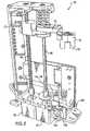
- the sample handling system 10includes a carrier transporter 50 that consists of a robotic device having a robotic arm 52 to move the carriers 40 as required for testing and retesting (see FIG. 6 ).
- the robotic arm 52has a gripper device 54 that picks up the carrier 40 by a support tab 48.
- the robotic transporter 50includes a drive motor 58 that is controlled by a programmable computer 60.
- the robotic arm 52traverses the length of the loading platform 30 by a timing belt 56.
- other meanscan be used to move the robotic arm 52.
- the transporter 50is capable of lifting a carrier 40 a height just slightly more than the total height of the carrier 40 holding a tube 42 in the loading rack 30.
- the vertical motion of the transporter 50is created by a lead screw 90 driven by a stepping motor 92.
- the robot transporter 50can also rotate a carrier 40 through a 210 degree range of motion between positions for barcode reading, access to carrier slots, access to a carrier positioner 80, and access to a reagent storage location.
- the rotational motion of the transporter 50is provided by a spline shaft 96 coupled to a stepping motor 97.
- the spline shaft 96allows the robotic arm 52 to move vertically while maintaining accurate angular positioning.
- the preferred embodimentincludes specific means to move the robotic transporter, it is understood by a person skilled in this art that other means could be used to move the transporter 50.
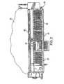
- the present sample handling system 10also includes a carrier positioner 80 located adjacent a diagnostic module 20 for conducting tests on the samples in the test tubes 42 (see FIG. 5 ).
- the carrier positioner 80has a plurality of openings 86 for receiving carriers.
- the positioner 80can position at least two complete carriers underneath the testing point(s) of a processing module, allowing the processing module to aspirate from one carrier 40 while the transporter 50 loads another carrier 40 on the positioner 80 to maintain system throughput.
- the carrier positioner 80includes a carriage 81 on a lead screw 82 driven by a stepping motor 84 in response to commands of the computer 60.
- the positioner 80is driven by a lead screw 88, the positioner 80 could be driven by other known driving means such as a belt, a chain, an air cylinder, or a linear motor.
- the positioner 80may be a variety of configurations, including having multiple openings 86 for routine carriers and high priority carriers.
- the carrier positioner 80has four openings 86 to accommodate the needs of several different types of processing modules using common hardware to reduce the overall product cost of the system (see FIG. 5 ).
- the positioner 80is configured to adapt to a variety of diagnostic modules 20. For example, two openings may be used for one pipetter and the other two openings for a different pipetter in the same diagnostic module 20. Alternatively, two openings may accommodate solely high priority sample carriers while the other two openings accommodate routine sample carriers.
- the robot transporter 50executes the following six basic carrier handling operations: 1) pick up carrier 40 from loading rack 30; 2) place carrier 40 into loading rack 30; 3) place carrier 40 onto positioner 80; 4) pick up carrier 40 from positioner 80; 5) present carrier 40 to a barcode reader 70; and 6) scan trays 35 for carriers 40.
- the robot transporter 50includes nine sensors for monitoring the correct operation of the system. Due to the unique value and hazards of the biological samples being transported, a high degree of capability to monitor and verify the operation of the transporter 50 is important.
- a first reflective sensor 102 on the transporter 50is used to determine the presence of a carrier 40 in a tray 35 or slot 32.
- a second (carrier slot alignment) sensor 104is used to verify correct alignment between the transporter 50 and the carrier slots on the loading rack for pick up and placement of the carriers.
- a third (carrier positioner alignment) sensor 106is used to verify alignment between the transporter and the openings 86 in the positioner 80.
- a fourth reflective sensor 107is used to determine if a carrier 40 is present on the positioner 80.
- the horizontal, rotational, and vertical motions of the transporter 50are monitored by fifth, sixth, and seventh sensors 108,110,112.
- An eighth sensor 114positioned with the rotational motion sensor 110, is used to verify the correct rotational position of the robotic arm 52.
- Located on the robotic arm 52is a ninth sensor 116 used to verify that the carrier 40 is properly engaged in the arm 52 for safe transport.
- the preferred embodimentincludes the above-described nine sensors, it is understood by a person skilled in this art that other means could be used to monitor and verify the operation of the transporter 50 and the robotic arm 52.
- a bar code reader 70is included in the present sample handling system to read carrier and sample identification. Bar coded labels are attached to the carriers 40 and, optionally on the sample tubes 42.
- the carrier 40is scanned once with a barcode reader 70 when the carrier 40 is first selected. After being scanned, the carrier 40 is moved by only the transporter 50 or the linear positioner 30. At this point, all motions of the carrier 40 generate position and alignment feedback to the computer 60, so the carrier identification only needs to be read by the barcode reader 70 once.
- diagnostic modules 20can be employed with the present random sampling handling system 10, including immunoassay modules or clinical chemistry test modules.
- suitable diagnostic modulesinclude ARCHITECT.RTM. i1000, i2000, and c8000 processing modules, manufactured by Abbott Laboratories, Abbott Park, Illinois.
- a plurality of access covers 94are positioned over the loading rack 30.
- an interlock connected to the access cover 94preferably will indicate a breach of positive identification, preferably requiring the barcode reader 70 to rescan the carriers 40.
- an operatorloads the trays 30 or individual carriers 40 onto the loading rack 30. Either the operator inputs into the computer the patient sample identification and the test orders or this information may be downloaded into the computer 60 from a lab information system. A test order may require a plurality of separate assays.
- the programmable computer 60determines the order of the different sample tests based on a preprogrammed priority. The system detects the presence of the carriers 40 and selects one for sampling. The computer 60 activates the robotic transporter 50 to pick up the selected carrier 40 from the loading rack 30 and transport the carrier 40 past the bar code reader 70 to identify the carrier 40 and the sample tubes 42, the bar code data is sent to the programmable computer 60.
- Tests previously programmed in the computer 60are assigned to each tube 42 in the carrier 40.
- the transporter 50then delivers the carrier 40 to the positioner 80.
- Software in the computer 60controls the movement of the positioner 80, moving the carrier 40 to a predetermined location adjacent a testing site or pipetter on the diagnostic module 20.
- the pipetterwithdraws the sample from a tube 42 for testing.
- the robotic arm 52loads the carrier 40 and then moves and returns the carrier 40 to its assigned location on the loading rack 30. While the tubes 42 of one carrier 40 are being aspirated, a second carrier 40 can be loaded onto the carriage 31for testing. At this point, the status indicator 74 will show a hold status for the carrier 40 until the computer 60 makes the retest decision. If a retest is needed, the carrier 40 will be selected again with the same process described above, but without a bar code scan. The robot 50 continues to pick up carriers 40, scan and place the carriers 40 as required. The status indicator 74 at each tray 35 or slot 32 will show a completed tray of carriers 35 or carrier 40 when retesting is not required. The operator should remove the completed carrier 40 or tray of carriers 35 when they have been released for unloading.
- Positive identification of the carrierspreferably is considered violated if an access cover 94 of the sample handling system 10 is opened. When an access door 94 is opened all carriers 40 preferably must be rescanned before further testing to provide positive identification. Further, positive identification of a carrier 40 is violated if a carrier 40 or a tray 35 on the loading rack 30 is removed prematurely. At this point the carrier 40 or tray 35 that was removed prematurely preferably must be replaced and rescanned. Slot and tray sensors 98 are monitored continuously to identify such violation of the positive identification. The programmable computer 60 rapidly checks the status of each individual tray or carrier sensor 98 in sequence. If a change in sensor state is observed, the computer 60 can determine that a carrier 40 or tray 35 has been removed and the identity of the contents can no longer be assured until the carriers 40 in question are re-scanned.
- the robot arm 52cannot access the linear positioner 80 while it is moving. For example, if the positioner 80 accommodates two carriers 40, and two carriers 40 are already on the positioner 80, no preemption is allowed for a high priority or stat sample.
- the high priority testingpreferably must wait until the carrier 40 in process is complete. At this point, the completed carrier 40 may be unloaded, the stat sample will be loaded and processed immediately. However, if only one carrier 40 is on the positioner 80, the stat or priority carrier may be loaded immediately and after the current sample is completed, the stat or priority carrier will be positioned for aspiration. Aspiration will resume on the remaining routine samples after all the tube samples on the stat carrier are aspirated.
- the computer softwarepreferably includes a preprogrammed or programmable priority order for processing samples.
- the carrierscan be selected for processing according to the following priority: 1-unload completed carriers; 2-move aspirated carriers to the loading rack; 3-stat or priority retests; 4-stat or priority tests; 5-stat or priority carrier pick, scan and move to holding area; 6-routine retests; 7-routine tests; 8-routine carrier pick, scan & move to holding area.
- This ordering of sample prioritieshas been shown to result in rapid response to high priority samples and maintaining high system throughput. It is understood by one skilled in the art that other priority schemes may be implemented to achieve different levels of performance and responsiveness.
- FIGS. 3 and 4Another preferred embodiment of the carrier handling system is shown in FIGS. 3 and 4 with a plurality of diagnostic modules 20. This alternative embodiment is very similar to that depicted in FIGS. 1 and 2 . Accordingly, like numerals in FIGS. 3 and 4 indicate the same elements as defined in connection with FIGS. 1 and 2 .
- the carrier handling system 10' in FIGS. 3 and 4includes at least two diagnostic modules.
- the diagnostic modules 20could include immunoassay, clinical chemistry, hematology, or other known diagnostic modules, or a combination of these modules.
- a carrier positioner 80is provided for each diagnostic module 20.
- a sample handling system 10' with a plurality of diagnostic modules 20enhances the productivity in a lab. Further a multiple module system reduces the requirement to separate or aliquot samples for distribution to different systems. In the present system, samples can be tested with the different modules without removing them from the system. This multiple module system also reduces the space requirements in a lab and can lower the costs of operation.
- a preferred embodiment of the carrier handler system 10'includes a loading rack 30 having seven urgent or priority carrier slots 32 and 12 bays 36 for receiving routine trays 35 holding five carriers 40 each.
- Only one carrier transporter 50 and barcode reader 70are preferably used for the present system, regardless of size.
- Appropriate control softwareis used for the present system to select carriers 40 for testing and retesting based on a predetermined priority, direct the operation of the mechanisms, and monitor the system for correct operation.
- the present sample handling systemis modular and scalable to different sizes of processing modules and may be used for single and dual module systems.
- the systemprovides random access to sample carriers in the loading platform. This random access capability allows the system to access and process high priority samples rapidly. This capability also allows the system to balance the workload of two processing modules with different throughput capabilities. After samples are processed initially, the samples can be returned to the loading platform and then accessed again when the initial testing is complete to provide automated retest capability. This automated retest capability preferably does not require any additional intervention by the operator. Random access assures the samples to be retested can be processed in the shortest possible time.
- the systemis mechanically simple, which minimizes system cost and maximizes system reliability.
- the present systemis self-contained and can be assembled and tested independently of the processing modules for ease of manufacture and installation in the field.
- the second and third sensors 104 and 106 on the transporter 50verify correct alignment of the carrier 40 with the linear positioner 80 and the loading rack 30 respectively.
- the first sensor 102verifies the presence of a carrier 40 on the loading rack 30 and the fourth sensor 107 (not shown) verifies the presence of a carrier 40 on the positioner 80.
- the systemincludes frequent software verification of the operation of the sensors.
- a diagnostic analyzer systemincludes a loading bay 120 with a loading tray, which is configured to receive both sample and reagent containers 122,124. To insure stability of samples and reagents refrigeration may be included in the loading tray area.
- the sample and reagent containers 122,124are held in sample and reagent carriers 126,128, respectively.
- Robotic transporter 130is configured for linking to and transporting both the sample and reagent carriers 126,128.
- the robot transporter 50can rotate a carrier 40 through a 210 degree range of motion between positions for barcode reading, access to carrier slots, access to a carrier positioner 80, and access to the reagent storage location.
- the transporter 130preferably has random access to any of the sample carriers 126 or reagent carriers 128, regardless of where they are positioned in the loading bay 120.
- the reagent carriers 128are shown in groups to the right of the sample carriers 126, but the preferred transporter 130 and loading bay 120 can accommodate the carriers 126,128 in any position and in any order, even with reagent carriers 128 interspersed between sample carriers 120. In an alternative embodiment, however, separate bays are provided for sample carriers 126 and reagent carriers 128.
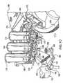
- the preferred embodimentpreferably has an aspiration tray with a sample positioning shelf 132, as shown in FIG. 8 , which can be free of any mechanism to move the sample carrier therealong.
- the transporter 130is preferably configured to reposition the sample carriers 126 along the shelf 132 as needed for access by the diagnostic module 136.
- the sample container 122 that is to be accessed by the pipetter 134 of the diagnostic module 136is positioned in a pipetting location, which is preferably adjacent a notch 138 in an upright wall of the shelf 132.
- the notch 138is configured to receive the end of the pipetter 134 as it is moved downwardly towards the contents of the sample container 122.
- the transporter 130repositions the sample carriers 120 along the shelf 132.
- the shelf 132is preferably sufficiently large to accommodate a plurality of sample carriers 126, each of which can be repositioned by the transporter as needed for access by the pipetter 134.
- Shelf 132preferably has a bottom support surface 142 and a front upright wall 144 that is sufficiently high to prevent the sample carrier 126 from sliding off the shelf, as well as an upright back wall 146.
- the back wall 146is preferably taller than the front wall 144, the carrier 126, and any containers 122 that are held in the carrier 126, and promotes sterility in the diagnostic module 136, which is preferably disposed behind the back wall 146.
- the sample carrier 126has slots 140 aligned axially with respect to the openings in which the sample containers 122 are carried.
- the slots 140permit scanning of a bar code or other identifying feature that is present on the containers 122.
- another bar code or other identifying featurecan also or alternatively be present on the sample carrier 126 itself.
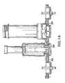
- the carrier 128has a carrier body 150 that includes holding portions 152-154, each of which is configured for holding a reagent container 124.
- the three holding portions 152-154preferably have a structure for a snap-fit connection to the base of a container 124.
- Holding portion 154additionally includes nubs 156, which can be supported on upstanding posts 158 and which are configured to clip about an enlarged diameter portion of the base of an alternative reagent container (not shown) that does not have the snap-fit features located on other reagent containers.
- Holding portion 152is configured for moving with respect to the carrier body 150 to move a reagent container 124 that is attached thereto for a constant mixing or stirring effect. This is desirable, for example, when the reagent includes microparticles that require constant motion to maintain a generally homogenous suspension. This holding portion 152 is movable with respect to the body 150 to produce this relative motion.
- An engagement portionsuch as gear 170
- holding portion 152is coupled or otherwise associated with holding portion 152, such that the gear 170 is drivable by a member external to the carrier body 150 to rotate holding portion 152.
- the gear 170is connected by a shaft 172 to the rotatable holding portion 152, as shown in FIG. 10 .
- a different type of engagement portioncan be used, or an on-board drive, such as a motor, can be mounted to the reagent carrier body 150.
- only one of the holding portionsis rotatable or movable with respect to the carrier 128 for producing the stirring in the reagent containers 124
- more than one of the holding portionscan be rotatable and more than one can be associated with the gear 170 for driving the motion relative to the carrier body.
- the gear 170preferably is disposed near one end of the carrier body 150, preferably opposite from transporter coupling 162, described below.
- the gear 170preferably is exposed on a lower side of the carrier body 150, on an opposite side from the part of the holding portions that are configured for connecting to the containers 124.
- Holding portion 152can be elevated with respect to holding portions 153, 154, and preferably accommodates a container 124 that is shorter than the containers 124 placed on the other holding portions 153, 154, preferably to position the upper ends of the containers 124 at substantially the same height.
- One end of the carrier body 150includes a handle portion 160 to facilitate grasping or holding of the loaded carrier by band by a user.
- the handle portion 150preferably is configured as a curved inverted hook with a space large enough to comfortably receive at least one finger of the user.
- a transporter coupling 162is provided, which is preferably similar to a transporter coupling 145 of the sample carrier 126 shown in FIG. 8 .
- the transporter coupling 162 of the preferred embodimentincludes an angular hook portion that the transporter is capable of coupling to for lifting, manenvering, and transporting the carrier to different parts of the diagnostic system.
- the preferred reagent carrier 128additionally has an identifying feature, such as a bar code 164.
- the identifying featurecan be a one- or two-dimensional bar code, such as a Code 128 type barcode, or other feature that can be identified by the system.
- the systemincludes an identification device which can have a bar code reader 166 or other identification device adapted to interpret and identify information of an identifying feature on the carriers 126 and/or the containers 124.
- the identifying featureis disposed on the containers 124, and can by accessed or read by the identification device when the containers 124 are loaded on the carrier 128.
- the identification deviceis associated with the transporter 130 such that an action of the transporter 130 can identify the type of contents in the containers 124 on each carrier 128.
- the transporter 130can be provided with a sensor mounted thereon that can sense an identifying feature on the carriers 128 or containers 124.
- the transportercan sense the physical dimensions of the carriers it is picking up. For instance, the vertical height of the reagent carriers 128 or a portion thereof can be different than the height of the sample carriers 126. In one embodiment the height at which the sample and regent containers are held in the carriers in the loading bay is different and sensed by the identification device to initially determine whether the contents are reagents or samples. As shown in FIG.
- loading tray pockets 302catch the wider reagent container base 304, but do not catch the narrower sample carrier base 306.
- the reagent containeris positioned higher than the sample carrier within the loading tray.
- the height at which the transporter 130 contacts or engages to lift the respective carrier 126,128is used by the controlling computer to identify the contents as samples or reagents.
- an initial determination of the type of contentsis made, such as by determining the height of the carrier transported, and an additional positive and individual identification is made of the contents subsequently, such as by the barcode reader.
- the bar code reader usedcan read both one- and two-dimensional bar codes, as one-dimensional bar codes are preferably used on the sample containers, while two-dimensional bar codes are used on the reagent carriers.
- the reagent containers 124 and sample carriers 126can additionally be labeled with identifying features.
- the transporter 130When the transporter 130 is directed by the controlling computer to pick up a carrier 126, 128, it positions the carrier 126,128 for scanning by the bar code reader 166. This enables the system to determine the type of contents that are carried on the carrier. If the system determines that the transported carrier is a sample carrier 126, then the transporter 130 will position the carrier 126 in the appropriate location on the aspiration tray shelf 132. On the other hand, if the system determines that a reagent carrier 128 is being transported, than that carrier 128 can be positioned in a reagent positioning area..
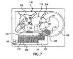
- the preferred reagent positioning areaincludes a carousel 168, which is configured to move and preferably rotate about its axis to position the reagents thereon in a location in which they can be accessed when needed by the pipetter 134.
- the carousel 168 of the preferred embodimenthas one or more platforms 174 that form bays in which the reagent carriers 128 are received, as shown in FIG. 10 .
- Retention memberswhich include a first portion associated with the bays, are configured for locking the carriers 128 to the carousel 168 and releasing them for the transporter 130 to retrieve and transport the carriers 128 to a different location in the device when they are no longer needed on the carousel 168 such as when the reagents thereon have been used up.
- the portion of the retention member that is disposed on the carousel 168preferably comprises fixed stirrups 176 that form a loop with an opening extending radially therethrough with respect to the carousel 168.
- Stirrups 176are positioned in dimensions to correspond with feet 178 of a second portion of the retaining member, which are associated with the carrier body 150 and feet 178, preferably extending downwardly from the body 150, as shown in FIG. 11 .
- the feet 178 of the preferred embodimentpreferably extend downwardly no further than the remaining lowest portion of the carrier 128, which in the preferred embodiment is the lowest portion of the carrier body 150. This enables the carrier 128 to be placed in a flat surface when not being used in the device.
- the transporter 130is operated to lower the carriers 128 onto the carousel 168, preferably with the feet 178 radially aligned with the stirrups 176.
- the feetare received within the opening in the stirrups 176 in an association such that the stirrups 176 retain the feet 178 against axial or upward removal from the carousel 168.
- the feet 178 and stirrups 176comprise latchable portions that latch together to assist in substantially locking the carrier 128 to the carousel 168.
- an activation member 180is positioned and configured adjacent the carousel 168 for operation by the transporter 130 to control the retention members.
- the activation member 180includes a bar 182 that is accessible by the transporter 130, such that when the transporter 130 moves adjacent the carousel 168, the bar 182 is depressed into the carousel 168.
- Bar 182is preferably pivotably attached to a lever 184 that is pivotable about axis 186.
- a rod 138At the other end of the lever 184 is a rod 138 that preferably protrudes generally axially for contacting a locking member 190.
- the activation member 180 and the locking member 190are preferably disposed beneath the carousel 168 on a side opposite from the carrier 128.
- the locking member 190preferably has a tab 192 that extends upwardly through the platforms 174 and protrudes on the upper side of the carousel 168.
- the transporter 130lowers the carrier 128 so that the tab 192 is received in an opening 194 of the carrier 128. With the carrier 128 seated on the carousel 168 and the tab 192 received in the opening 194, the transporter 130 moves away from the carousel to perform another transporting operation on a different carrier 126,128.
- spring 202resiliently biases the lever 180 to a position permitting the locking of the carrier 128 to the carousel.
- the locking member 190has a guide shaft 204 about which is mounted a spring 206.
- the physical contact of the transporter 130 against the activation membermechanically displaces and operates the activation member to lock or unlock the carrier 128 to or from the carousel 168.
- the contact between the transporter 130 and the activation membercan cause an electrically or otherwise driven mechanism to lock or unlock the carrier.
- a solenoid or motoroperates the locking member, and this can be completely controlled by the controlling computer, without directly being activated by any physical contact from the transporter 130.
- the same motion of the carrier 128 towards the locked position caused by the locking member 190preferably also meshes gear 170 with an engagement portion that is associated with the carousel 168.
- This engagement portionis preferably associated with the carousel 168, and in the preferred embodiment comprises a ring gear 208 that is preferably stationary. With the gear 170 and ring gear 203 meshed, rotation of the carousel 168 about the ring gear 208 spins both the gear 170 and the container 124 mounted to holding portion 152.
- the preferred container 124includes internal ribs 210, which improve stirring and mixing of the contents therein.
- the actuation portion 180is preferably mounted to a stationary portion of the device that does not rotate with the carousel 168.
- the locking members 190 and the rod 188are resiliently biased by springs 202,206 to positions so that rod 188 is aligned with gaps adjacent the locking members, which are aligned circumferentially along the carousel 168.
- the rod 188passes adjacent to the locking members 190, preferably without coming in contact therewith, and substantially without interfering with or causing the locking members 190 to move from their locked positions.
- a carrier sensor 212is preferably mounted on a fixed portion in the interior of the carousel 168.
- the carrier sensor 212is configured for detecting the presence of a carrier 128 on the carousel 168 or a carrier 128 in the locked position on the carousel 168.
- the preferred carrier sensor 212is a Hall effect sensor that is configured to detect the presence of a magnet 213 embedded in the handle portion 160 of the carrier 128.
- other kinds of sensorscan be used, such as a capacitive sensor to directly detect the presence of the carrier material, which is preferably plastic.
- the sensor 212preferably transmits a signal to the controlling computer to indicate the presence or absence of the carrier 128 in the locked position on the carousel 168 at the loading location, where the transporter 130 can load the reagent carrier 128 onto the carousel 168.
- the controlling computerkeeps track of the position on the carousels 128 holding each reagent in the reagent containers 124.
- the pipetter 134preferably has a pivoting arm 214 that can pivot along an arc 216.
- the rotational position of the carousel 168 and the pivoting arm 214are controlled by the controlling computer to intersect the selected reagent container with the locus of the pipetter 134.
- the pipettercan draw the desired amount of reagent to transmit it to a diagnostic testing area 218 of the diagnostic module.
- the pivoting arm 214is also movable to position the pipetter over the sample container 122 from which a sample is to be drawn, and the drawn sample can also be delivered to a diagnostic testing area 218.
- reagent positioning devicesother then carousels can be used for positioning the reagents and desired location for access by the pipetter, and the ring gear that drives the gear on the carrier to rotate one of the holders can also be driven to rotate without requiring any motion from the carousel to mix the microparticles or any other substance in the storage container.
Landscapes
- Chemical & Material Sciences (AREA)
- Health & Medical Sciences (AREA)
- Immunology (AREA)
- Pathology (AREA)
- Analytical Chemistry (AREA)
- Biochemistry (AREA)
- General Health & Medical Sciences (AREA)
- General Physics & Mathematics (AREA)
- Physics & Mathematics (AREA)
- Life Sciences & Earth Sciences (AREA)
- Chemical Kinetics & Catalysis (AREA)
- Clinical Laboratory Science (AREA)
- Engineering & Computer Science (AREA)
- Robotics (AREA)
- Automatic Analysis And Handling Materials Therefor (AREA)
- Holo Graphy (AREA)
- Transition And Organic Metals Composition Catalysts For Addition Polymerization (AREA)
- Analysing Materials By The Use Of Radiation (AREA)
Abstract
Description
- The present invention relates to a sample and reagent handling system for automatically testing samples with a diagnostic module. More particularly, the invention relates to a sample handling system in which sample and reagent carriers are placed in a loading bay and transported by a transporter to a different location depending on the contents of the carriers. The invention also relates to a diagnostic module with a mechanism for locating the carriers in an aspiration position.
- In the past, sample handling systems had a single path carrier that would stop at specified locations as desired for testing. In these single path systems, if retesting or preemptive prioritization of a sample were required, the tube would have to travel around the entire module system to be tested or retested. This resulted in either significant delay in testing and retesting or very complex, expensive carrier routing mechanisms.
- An example of a single path sample handling device is disclosed in
U.S. Pat. No. 5,876,670 to Mitsumaki . In Mitsumaki, a sample carrier, holding a plurality of test tubes, is transferred to the analyzer modules by a transporting belt driven by a motor. All the sample carriers on the transporting belt pass through the sampling position for the first analyzer module and preferably must be transferred to a receiving position to reach the sampling position for the second analyzer module. When a sample needs to be retested, then the operator returns the sample carrier to the beginning of the transporting belt. An urgent sample supply portion is provided on one end of the belt near the sample supply portion, allowing urgent sample racks to be processed before the general racks. In Mitsumaki, the sample handling system processes samples sequentially along the transporting belt and does not automatically retest samples. - Another example of a prior sample handling system is disclosed in
U.S. Pat. No. 5,665,309 to Champseix et al . The Champseix et al. device comprises a holding rack for a plurality of test tubes; a sampling station for sampling the contents of a tube; and a gripping device for withdrawing a tube from a selected position on the rack, bringing the tube to the sampling station and returning the tube back to its selected position. The gripping device moves the individual tubes from a rack to the sampling station. However, the Champseix et al., sample handling device does not disclose a method for automatically retesting samples or processing stat samples. U.S. Pat. No. 5,260,872 to Copeland discloses an automated testing system for the quality testing of production samples, comprising a loading station for receiving a test tube rack containing a plurality of test tubes; a pipetting station; a bead-drop station; and a robotic device having an arm adapted to pick up a test tube rack from the loading station, move the rack to the pipetting station so the fluids can be pipetted into the test tubes; move the rack to the bead-drop station; and return the rack to the loading station in accordance with a computer program. When the Copeland test tube rack is returned to the loading station the tubes may be removed and disposed of and the rack is then loaded with a fresh set of test tubes. The Copeland system does not accommodate for automatic retasting or testing of stat samples.- In the past, reagents have been loaded manually in an automated testing system with a diagnostic module. Reagent replacement is often required in the middle of testing due to consumption of the reagent in a kit or expiration of a reagent. In addition, a reagent may be needed when the system needs to run more test types, analytes, in a day than there are reagent positions in the analyzer. The manual loading of the reagents often resulted in interruption of testing in process or at least a loss of throughput.
EP-A-0 435 481 discloses "packs" comprising two reagent containers and a corresponding solid phase or reaction container being held together by a snap-fit pack top which fits over reagent container access openings and the respective solid phase container access opening without obstruction. The packs of containers and the corresponding container are mounted on a portion of an automated immunoassay machine carousel platform. The packs are removably mounted on the carousel by reagent container formed base portions and solid phase container base portions fitting into corresponding recesses formed in the carousel. In an alternative embodiment, a wheel is provided in the form of a gear wheel adapted to mesh with a gear track being integrally moulded into the lower circumference of container.EP 0 525 577 A discloses a reaction vessel holder that is a tube holder being adapted to receive a reaction vessel having at the upper portion thereof a concentric chamber for holding reaction reagents. The vessel is nutated by an automatic apparatus. More in detail, a pin of the automatic apparatus engages the bottom end of the mixing vessel and the apparatus then spins the cylinder moving the engaged end of the vessel into an orbit.US 2003/0054542 A1 discloses a multi axis mixer including a rotating turntable structure rotatably mounted on a center shaft supported in center bearings to a fixed base. Four container holders are disposed on the ends of the arms of turntable frame. The multi-axis mixer usually rotates during operation of the analyzer to agitate the fluid contents of the containers to thereby keep the target capture reagent in suspension, stopping only briefly to permit pipette unit to withdraw an amount of mixture from one of the containers.- Documents
EP-A-0 502 638 andUS-A-5 795 784 disclose other automated analyzers including a concentric carousel platforms comprising slots being loaded with containers, either sample containers or reagent containers. - The present invention relates to an assay testing diagnostic analyzer and a handling system thereof. The handling system includes a loading bay for receiving and holding a plurality of carriers as according to
claim 2. An identification device is configured for identifying an identifying feature of the carriers or containers to determine the type of contents loaded on each carrier. A transporter is configured for transporting the carriers from the loading bay to a first or second location depending on the determined type of contents on each carrier. A diagnostic process is performed using the contents. The transporter preferably has random access to the plurality of carriers in the loading bay. - The identification device is configured for identifying the contents of the carriers at least as either samples or reagents. The identification device is associated with the transporter such that the transporter can transport the samples to the first location and the reagents to the second location. Although the loading bay can have a sample loading area and a separate reagent loading area, in a more preferred embodiment, however, a single loading area is provided in which the sample in reagent carriers can be positioned in any order. The identification device is preferably configured for identifying the type of contents independently of where in the loading bay the carriers are loaded. Most preferably, the transporter can transport the carriers from and/or to substantially any location in the loading bay and/or the respective first or second location.
- An advantage of the present handling system is that reagents can be loaded and unloaded as regents are consumed or expired, without interrupting the operation of the automated testing or reducing the thoughput of the system. Further, the present handling system includes the ability to exchange one analyte for another,as testing requires, without interrupting the operation of the testing or reducing the throughput of the system.
- A first carrier support member for example an aspiration platform, includes the first location and is disposed for access by a diagnostic module configured for performing the diagnostic process. The transporters can be configured for transporting the carriers from a loading bay to the first carrier support member and additionally to move the carriers between different locations on the first carrier support member. The transporter can preferably move the carriers to and from a plurality of first locations on the carrier support, for example, to position more than one carrier on the support member at any time. The first carrier support member can include a positioner that can be configured to receive and move the carriers for access by the diagnostic module for testing the contents of at least one of the plurality of the the containers of the carrier.
- Preferably, the identifying feature comprises an optically readable feature. The identification device can thus include an optical reader that is capable of reading this feature. The identifying features on the carriers preferably identify them as holding reagents or samples. Preferably, the individual samples and reagents can also be individually identified by the identification device. Alternatively, the carriers can be distinguished by other physical differences that can be detected by a sensor, or the different types of carriers can be in slightly different orientations to allow them to be identified by the position of the carrier. In another embodiment, the identifying feature is an identifiable physical characteristic, such as the height of the carrier.
- A programmable controlling computer can control the movement of the transporter and other moving parts of the device based on input data and a pre-programmed priority order for processing the contents on the carriers. In a preferred embodiment, samples to be tested are loaded into the diagnostic system, and reagent carriers that hold containers with reagents are also loaded into the system. The reagent carriers are transported to reagent support members, such as on a carousel, automatically by a transporter. The samples are tested with the appropriate reagents depending on the test being conducted.
- A carrier as according to the invention is defined in
claim 2 - The first engagement member includes a gear that is configured for meshing with teeth of the second engagement member, or a friction wheel that is in frictional engagement with the second member. In an embodiment in which the carriers are mounted on a carousel, the second engagement member can include a ring gear or friction wheel disposed adjacent a moveable portion of the carousel to mesh with the gear of or contact the friction wheel on the carrier. Thus, as the carousel rotates around the ring gear or friction wheel, the carrier gear or friction wheel causes a rotation of the container mounted therewith.The ratio between the ring gear and the carrier gear can be made at an integer to facilitate the reading of a bar code located on the reagent bottle when the reagent carriers are removed from the reagent carousel.
- The preferred holding portions are configured for gripping the containers positioned thereon. Also, the body can have a handle portion to facilitate grasping the loaded carrier by hand. A transporter coupling portion can be provided as well for coupling with the transporter to enable the transporting of the carrier between different locations in the device.
- In the preferred embodiment, a positioning device is configured for receiving and positioning the carriers for access by the diagnostic module. This positioning device is preferably provided for receiving the reagent carriers and includes the second location and is the second carrier support member. A retention member associated with the positioning device is configured for locking the carrier to the positioning device. The retention member is preferably operably associated with the transporter for releasing and including the carrier for the transporter to transport the carrier therefrom. This operative association can be provided by a mechanical connection activated by contact therebetween, an electrical connection, or it can be provided by the controlling computer, which tracks the positions of the transporter and the positioning device.
- The preferred positioning device is a rotatably driven carousel that is driven to provide access to the contents of the carrier by the diagnostic module. An activation member of the preferred embodiment is operably associated with the transporter for releasing the carrier upon contact between the transporter and the activation member. A carrier-locking member is preferably configured for moving with respect to the carousel in association with the carrier to lock and unlock the carrier. The activation member is preferably displaced by the transporter to move the carrier-locking member to cause the locking and/or unlocking of the carrier. Preferably, the locking member displaces the carrier with respect to the carousel to move the carrier into a locked position. The carousel is preferably rotatable or otherwise movable with respect to the activation member, and the locking member is preferably mounted to the carousel. The activation and the locking member are disposed such that the activation member in the inactive position does not interfere with the locking member during the carousel rotation.
- The retention member also preferably comprises a latching member configured for latching to a latchable portion of the carrier in the locked position, preferably upon relative movement between the latching member and the latchable portion. The locking member is preferably moveable with respect to the carousel and is associated with the carrier to move at least a portion of the carrier with respect to the latching member for locking and unlocking the carrier. Additionally, the locking member can have a tab that is received in the recess of the carrier to slide the carrier with respect to the latching member.
- A carrier sensor can be provided for detecting the presence of the carrier on the positioning device. This carrier sensor can be, for example, a Hall effect, optical or a capacitive sensor.
- Additional advantages of the invention will be realized and attained by the apparatus and method particularly pointed out in the written description and claims hereof, as well as from the appended drawings. It is to be understood that both the foregoing general description and the following detailed description are exemplary and are intended to provide further explanation of the invention claimed.
FIG. 1 is a perspective view of a preferred embodiment of the sample handling system of the present invention;FIG. 2 is a top plan view of the sample handling system ofFIG. 1 with access doors removed;FIG. 3 is a perspective view of a preferred embodiment of the sampling handling system with two diagnostic modules;FIG. 4 is a top plan view of the sample handling system ofFIG. 3 with access doors removed;FIG. 5 is a perspective view of a preferred embodiment of a carrier positioner;FIG. 6 is a perspective view of a preferred embodiment of a transporter;FIG. 7 is a top view of another embodiment of a diagnostic analyzer system according to the present invention;FIG. 8 is a perspective view of an aspiration platform thereof, including a sample receiving tray;FIG. 9 is a perspective view of a preferred embodiment of a reagent carrier;FIGS. 10 and11 are top and bottom perspective views, respectively, of a reagent positioning and locking system of the embodiment ofFIG. 7 in an unlocked position, with a carousel shown inFIG. 10 in cross-section but hidden fromFIG. 11 for clarity;FIGS. 12 and13 are top and bottom perspective views, respectively, of the reagent carrier in a locked position, andFIG. 14 is a front view of another preferred embodiment of a loading rack- The present invention relates to a random sample and reagent handling system for moving samples and reagents to and from a diagnostic module for automatic testing and retesting. The random handling system includes a loading rack for receiving a plurality of carriers as according to
claim 2. The carriers can include several tubes filled with samples. In a preferred embodiment, the sample carriers are arranged in a stationary linear array on a loading rack positioned in front of the diagnostic modules. The operator may load the carriers individually or in trays for convenient handling of multiple carriers. Individual carrier slots are provided for loading high priority or stat samples that require immediate processing. - A robotic device is provided to transport the carriers to and from the loading rack and to and from a carrier positioner adjacent the diagnostic module(s). The robotic device has an arm, which is controlled by a programmable computer, moving the carriers as required for testing and retesting. The system includes software that allows users to flexibly configure rules or criteria for retesting samples. These rules can also be utilized to change to another type of test depending on the results of a previous test. This can be a very cost effective approach that when utilized minimizes operator involvement in real time. The system also includes a software capability that can suspend the operation of the sampler handler in the event the user decides to change the test request(s) for a particular sample after loading the carrier.
- The carrier positioner is located adjacent a diagnostic module for positioning the carriers so the samples selected for testing can be aspirated by a probe. The positioner includes a carriage connected to a lead screw driven by a stepping motor in response to commands from the programmable computer. In a preferred embodiment, the carrier positioner can accommodate at least two carriers, allowing the processing module to test one carrier while the transporter loads another carrier onto the positioner to maintain the system throughput.
- A barcode reader is provided to read carrier and container identification. A bar code reader in the system reads bar coded labels attached to the carriers and the sample tubes or reagent bottles as the robotic device passes the carriers by the reader.
- Only one robotic device and barcode reader are preferably used for the present system, regardless of size. The invention can be dynamically configured for variable queue sizing depending on the user's particular workload. Additionally, the total capacity of the system can be changed based on peak loading requirements that vary across testing segments in the laboratory.
- In operation, the robotic arm picks up a carrier from the loading rack and travels past the bar code reader to identify the carrier and samples. Tests previously programmed in the computer are assigned to each tube in the carrier. The robotic arm delivers the carrier to be tested to the carrier positioner. The positioner is controlled by the computer to move the carrier to a predetermined location adjacent a pipetter on the diagnostic module. The pipetter aspirates samples from the tube for testing. When the tests are completed on all the tubes in the carrier, the robotic arm loads the carrier and returns the carrier to its designated location in the loading rack. While the tubes of one carrier are being aspirated, a second carrier can be moved to the carriage.
- The carrier handling system can include more than one diagnostic module. For example in one preferred embodiment, the carrier handling system includes two diagnostic modules, a clinical chemistry test module and an immunoassay module. A carrier positioner is provided for each diagnostic module in the system.
- The present invention provides a modular random sampling system that can be adapted to a variety of diagnostic modules. The present carrier handling system is modular and scalable to different sizes of processing modules and may be used for single or multiple module systems. The system provides random access to carriers on the loading rack. This random access capability allows the system to access and process high priority samples rapidly. This capability also allows the system to balance the workload of multiple processing modules with different throughput capabilities. After samples are processed initially, the sample carriers are returned to their slots in the loading area and then accessed again when the initial testing is complete to provide automated retest capability. This automated retest capability does not require any additional intervention by the operator. Random access assures the samples to be retested can be processed in the shortest possible time. The system is mechanically simple, which minimizes system cost and maximizes system reliability. The present system is self-contained and can be assembled and tested independently of the processing modules for ease of manufacture and installation in the field.
- A system is also provided that processes samples for testing and retesting in a faster time and with more reliability than previous handling systems. The sample handling system of the invention can additionally provide faster processing of high priority samples while maintaining throughput of routine test samples.
- A system can be provided having a robotic assembly for moving a carrier with a plurality of test samples from a loading rack to a sample testing area and returning the carrier to the loading rack and having a programmable computer for (1) controlling the robotic assembly, (2) selecting carriers for testing based on predetermined priority, (3) achieving positive identification of the carriers and samples, and (4) identifying a breach of positive identification when an access door has been opened or a carrier has been removed prematurely.
- A preferred embodiment of the invention is a carrier handling system, generally designated by the numeral 10. As shown in
FIGS. 1 and2 , thepresent handling system 10 includes aloading rack 30 with a plurality ofslots 32 for receiving a plurality ofcarriers 40. Eachcarrier 40 can hold a plurality ofcontainers 42, such as tubes or cups, filled with samples. In this example, eachcarrier 40 can hold fivetubes 42. However, thecarriers 40 can be configured to hold either more orless tubes 42 depending on the system requirements. - The
sample carriers 40 are arranged on theloading rack 30 in a stationary linear array near theprocessing modules 20. The operator can load thecarriers 40 onto the loading rack orplatform 30 of a loading bay individually intoslots 32 or intrays 35 for convenient handling of multiple carriers. Theloading rack 30 can be configured in different shapes such as circular with slots aligned around the circular tray. Theloading rack 30 includes aroutine loading area 31 and an urgent orstat sample area 33. In a preferred embodiment of the present invention, theroutine loading area 31 comprises a plurality ofbays 36, eachbay 36 accommodating atray 35. Eachbay 36 includes adoor 38 attached to theloading rack 30. Eachdoor 38 includes a latch that is automatically released by insertion of atray 35. This latch is preferably difficult to actuate by hand to prevent an operator from affecting the operation of thecarriers 40. - The
carriers 40 may be loaded onto atray 35 before loading thetray 35 into theloading rack 30 from thefront 12 of thehandling system 10. Alternatively, a carrier can be loaded onto the tray previously loaded onto theloading rack 30. In this example, atray 35 accommodates up to five carriers and the loading rack accommodates sevenstat carriers 40 and fourroutine trays 35 holding up to 25 samples each. However, theloading rack 30 may be configured differently to accommodate peak loading requirements that vary across testing segments in the laboratory. - The
carriers 40 are positioned in the tray slots until selected for testing or retesting. Acarrier 40 is released for unloading immediately after retest or after all tests in thecarrier 40 are complete and no retests are required. Atray 35 is released for unloading when all thecarriers 40 in thetray 35 are released for unloading. A high priority orstat carrier 40 is loaded into the highpriority sample area 33. Acarrier 40 located in thehigh priority area 33 is transferred to thecarrier positioner 80 for aspiration and then is returned to thestat area 33 until aprogrammable computer 60 determines if a retest is needed. Astat carrier 40 is released for unloading after all tests are completed and any retest requests are aspirated. - A plurality of
status indicators 74 are provided to indicate to the operator when a completedtray 35 or anindividual carrier 40 in thehigh priority area 33 may be removed. For example, thestatus indicator light 74 is green to indicate the correspondingtray 35 orcarrier 40 can be accessed or thestatus indicator light 74 is amber to indicate thetray 35 orcarrier 40 is in process and should be left in place until completed. - The present
sample handling system 10 includes a means for detecting that anew tray 35 ornew carrier 40 in the high priority area has been loaded. A loading rack sensor 98 (not shown) is located in each bay or stat slot to detect the presence of a tray or carrier respectively. If a new tray is detected the contents of thetray 35 are scanned by afirst sensor 102 on thecarrier transporter 50 to determine if any carriers are in the tray. - In a preferred embodiment, the
sample handling system 10 includes acarrier transporter 50 that consists of a robotic device having arobotic arm 52 to move thecarriers 40 as required for testing and retesting (seeFIG. 6 ). Therobotic arm 52 has agripper device 54 that picks up thecarrier 40 by a support tab 48. Therobotic transporter 50 includes adrive motor 58 that is controlled by aprogrammable computer 60. In the preferred embodiment, therobotic arm 52 traverses the length of theloading platform 30 by atiming belt 56. However, it is understood by a person skilled in this art that other means can be used to move therobotic arm 52. - The
transporter 50 is capable of lifting a carrier 40 a height just slightly more than the total height of thecarrier 40 holding atube 42 in theloading rack 30. The vertical motion of thetransporter 50 is created by alead screw 90 driven by a steppingmotor 92. Therobot transporter 50 can also rotate acarrier 40 through a 210 degree range of motion between positions for barcode reading, access to carrier slots, access to acarrier positioner 80, and access to a reagent storage location. The rotational motion of thetransporter 50 is provided by aspline shaft 96 coupled to a steppingmotor 97. Thespline shaft 96 allows therobotic arm 52 to move vertically while maintaining accurate angular positioning. Although the preferred embodiment includes specific means to move the robotic transporter, it is understood by a person skilled in this art that other means could be used to move thetransporter 50. - The present
sample handling system 10 also includes acarrier positioner 80 located adjacent adiagnostic module 20 for conducting tests on the samples in the test tubes 42 (seeFIG. 5 ). In the preferred embodiment, thecarrier positioner 80 has a plurality ofopenings 86 for receiving carriers. Thepositioner 80 can position at least two complete carriers underneath the testing point(s) of a processing module, allowing the processing module to aspirate from onecarrier 40 while thetransporter 50 loads anothercarrier 40 on thepositioner 80 to maintain system throughput. Thecarrier positioner 80 includes acarriage 81 on alead screw 82 driven by a steppingmotor 84 in response to commands of thecomputer 60. Although in the preferred embodiment thepositioner 80 is driven by a lead screw 88, thepositioner 80 could be driven by other known driving means such as a belt, a chain, an air cylinder, or a linear motor. Thepositioner 80 may be a variety of configurations, including havingmultiple openings 86 for routine carriers and high priority carriers. - In a preferred embodiment, the
carrier positioner 80 has fouropenings 86 to accommodate the needs of several different types of processing modules using common hardware to reduce the overall product cost of the system (seeFIG. 5 ). Thepositioner 80 is configured to adapt to a variety ofdiagnostic modules 20. For example, two openings may be used for one pipetter and the other two openings for a different pipetter in the samediagnostic module 20. Alternatively, two openings may accommodate solely high priority sample carriers while the other two openings accommodate routine sample carriers. - The
robot transporter 50 executes the following six basic carrier handling operations: 1) pick upcarrier 40 fromloading rack 30; 2)place carrier 40 intoloading rack 30; 3)place carrier 40 ontopositioner 80; 4) pick upcarrier 40 frompositioner 80; 5)present carrier 40 to abarcode reader 70; and 6) scantrays 35 forcarriers 40. - In as example the
robot transporter 50 includes nine sensors for monitoring the correct operation of the system. Due to the unique value and hazards of the biological samples being transported, a high degree of capability to monitor and verify the operation of thetransporter 50 is important. A firstreflective sensor 102 on thetransporter 50 is used to determine the presence of acarrier 40 in atray 35 orslot 32. A second (carrier slot alignment)sensor 104 is used to verify correct alignment between thetransporter 50 and the carrier slots on the loading rack for pick up and placement of the carriers. A third (carrier positioner alignment) sensor 106 is used to verify alignment between the transporter and theopenings 86 in thepositioner 80. A fourth reflective sensor 107 is used to determine if acarrier 40 is present on thepositioner 80. The horizontal, rotational, and vertical motions of thetransporter 50 are monitored by fifth, sixth, and seventh sensors 108,110,112. An eighth sensor 114, positioned with the rotational motion sensor 110, is used to verify the correct rotational position of therobotic arm 52. Located on therobotic arm 52 is aninth sensor 116 used to verify that thecarrier 40 is properly engaged in thearm 52 for safe transport. Although the preferred embodiment includes the above-described nine sensors, it is understood by a person skilled in this art that other means could be used to monitor and verify the operation of thetransporter 50 and therobotic arm 52. - A
bar code reader 70 is included in the present sample handling system to read carrier and sample identification. Bar coded labels are attached to thecarriers 40 and, optionally on thesample tubes 42. Thecarrier 40 is scanned once with abarcode reader 70 when thecarrier 40 is first selected. After being scanned, thecarrier 40 is moved by only thetransporter 50 or thelinear positioner 30. At this point, all motions of thecarrier 40 generate position and alignment feedback to thecomputer 60, so the carrier identification only needs to be read by thebarcode reader 70 once. - Many types of
diagnostic modules 20 can be employed with the present randomsampling handling system 10, including immunoassay modules or clinical chemistry test modules. Examples of suitable diagnostic modules include ARCHITECT.RTM. i1000, i2000, and c8000 processing modules, manufactured by Abbott Laboratories, Abbott Park, Illinois. - In a preferred embodiment of the sample handling system 10 a plurality of access covers 94 are positioned over the
loading rack 30. When anaccess door 94 is opened, an interlock connected to theaccess cover 94 preferably will indicate a breach of positive identification, preferably requiring thebarcode reader 70 to rescan thecarriers 40. - During operation of the present
carrier handling system 10, an operator loads thetrays 30 orindividual carriers 40 onto theloading rack 30. Either the operator inputs into the computer the patient sample identification and the test orders or this information may be downloaded into thecomputer 60 from a lab information system. A test order may require a plurality of separate assays. Once a sample is loaded, theprogrammable computer 60 determines the order of the different sample tests based on a preprogrammed priority. The system detects the presence of thecarriers 40 and selects one for sampling. Thecomputer 60 activates therobotic transporter 50 to pick up the selectedcarrier 40 from theloading rack 30 and transport thecarrier 40 past thebar code reader 70 to identify thecarrier 40 and thesample tubes 42, the bar code data is sent to theprogrammable computer 60. Tests previously programmed in thecomputer 60 are assigned to eachtube 42 in thecarrier 40. Thetransporter 50 then delivers thecarrier 40 to thepositioner 80. Software in thecomputer 60 controls the movement of thepositioner 80, moving thecarrier 40 to a predetermined location adjacent a testing site or pipetter on thediagnostic module 20. The pipetter withdraws the sample from atube 42 for testing. - When the tests are completed on all the
tubes 42 in thecarrier 40, therobotic arm 52 loads thecarrier 40 and then moves and returns thecarrier 40 to its assigned location on theloading rack 30. While thetubes 42 of onecarrier 40 are being aspirated, asecond carrier 40 can be loaded onto the carriage 31for testing. At this point, thestatus indicator 74 will show a hold status for thecarrier 40 until thecomputer 60 makes the retest decision. If a retest is needed, thecarrier 40 will be selected again with the same process described above, but without a bar code scan. Therobot 50 continues to pick upcarriers 40, scan and place thecarriers 40 as required. Thestatus indicator 74 at eachtray 35 orslot 32 will show a completed tray ofcarriers 35 orcarrier 40 when retesting is not required. The operator should remove the completedcarrier 40 or tray ofcarriers 35 when they have been released for unloading. - Positive identification of the carriers preferably is considered violated if an
access cover 94 of thesample handling system 10 is opened. When anaccess door 94 is opened allcarriers 40 preferably must be rescanned before further testing to provide positive identification. Further, positive identification of acarrier 40 is violated if acarrier 40 or atray 35 on theloading rack 30 is removed prematurely. At this point thecarrier 40 ortray 35 that was removed prematurely preferably must be replaced and rescanned. Slot and tray sensors 98 are monitored continuously to identify such violation of the positive identification. Theprogrammable computer 60 rapidly checks the status of each individual tray or carrier sensor 98 in sequence. If a change in sensor state is observed, thecomputer 60 can determine that acarrier 40 ortray 35 has been removed and the identity of the contents can no longer be assured until thecarriers 40 in question are re-scanned. - In the preferred embodiment, the
robot arm 52 cannot access thelinear positioner 80 while it is moving. For example, if thepositioner 80 accommodates twocarriers 40, and twocarriers 40 are already on thepositioner 80, no preemption is allowed for a high priority or stat sample. The high priority testing preferably must wait until thecarrier 40 in process is complete. At this point, the completedcarrier 40 may be unloaded, the stat sample will be loaded and processed immediately. However, if only onecarrier 40 is on thepositioner 80, the stat or priority carrier may be loaded immediately and after the current sample is completed, the stat or priority carrier will be positioned for aspiration. Aspiration will resume on the remaining routine samples after all the tube samples on the stat carrier are aspirated. - The computer software preferably includes a preprogrammed or programmable priority order for processing samples. For example, the carriers can be selected for processing according to the following priority: 1-unload completed carriers; 2-move aspirated carriers to the loading rack; 3-stat or priority retests; 4-stat or priority tests; 5-stat or priority carrier pick, scan and move to holding area; 6-routine retests; 7-routine tests; 8-routine carrier pick, scan & move to holding area. This ordering of sample priorities has been shown to result in rapid response to high priority samples and maintaining high system throughput. It is understood by one skilled in the art that other priority schemes may be implemented to achieve different levels of performance and responsiveness.
- Another preferred embodiment of the carrier handling system is shown in
FIGS. 3 and4 with a plurality ofdiagnostic modules 20. This alternative embodiment is very similar to that depicted inFIGS. 1 and2 . Accordingly, like numerals inFIGS. 3 and4 indicate the same elements as defined in connection withFIGS. 1 and2 . - The carrier handling system 10' in
FIGS. 3 and4 includes at least two diagnostic modules. Thediagnostic modules 20 could include immunoassay, clinical chemistry, hematology, or other known diagnostic modules, or a combination of these modules. Acarrier positioner 80 is provided for eachdiagnostic module 20. A sample handling system 10' with a plurality ofdiagnostic modules 20 enhances the productivity in a lab. Further a multiple module system reduces the requirement to separate or aliquot samples for distribution to different systems. In the present system, samples can be tested with the different modules without removing them from the system. This multiple module system also reduces the space requirements in a lab and can lower the costs of operation. - As shown in
FIG. 3 , a preferred embodiment of the carrier handler system 10' includes aloading rack 30 having seven urgent orpriority carrier slots bays 36 for receivingroutine trays 35 holding fivecarriers 40 each. - Only one
carrier transporter 50 andbarcode reader 70 are preferably used for the present system, regardless of size. Appropriate control software is used for the present system to selectcarriers 40 for testing and retesting based on a predetermined priority, direct the operation of the mechanisms, and monitor the system for correct operation. - The present sample handling system is modular and scalable to different sizes of processing modules and may be used for single and dual module systems. The system provides random access to sample carriers in the loading platform. This random access capability allows the system to access and process high priority samples rapidly. This capability also allows the system to balance the workload of two processing modules with different throughput capabilities. After samples are processed initially, the samples can be returned to the loading platform and then accessed again when the initial testing is complete to provide automated retest capability. This automated retest capability preferably does not require any additional intervention by the operator. Random access assures the samples to be retested can be processed in the shortest possible time. The system is mechanically simple, which minimizes system cost and maximizes system reliability. The present system is self-contained and can be assembled and tested independently of the processing modules for ease of manufacture and installation in the field.
- Several features are included in the present sample handling system to prevent incorrect carrier placement. First, the second and
third sensors 104 and 106 on thetransporter 50 verify correct alignment of thecarrier 40 with thelinear positioner 80 and theloading rack 30 respectively. In addition, thefirst sensor 102 verifies the presence of acarrier 40 on theloading rack 30 and the fourth sensor 107 (not shown) verifies the presence of acarrier 40 on thepositioner 80. Further, the system includes frequent software verification of the operation of the sensors. - Referring to
FIG. 7 , another embodiment of a diagnostic analyzer system includes aloading bay 120 with a loading tray, which is configured to receive both sample and reagent containers 122,124. To insure stability of samples and reagents refrigeration may be included in the loading tray area. Preferably, the sample and reagent containers 122,124 are held in sample and reagent carriers 126,128, respectively.Robotic transporter 130 is configured for linking to and transporting both the sample and reagent carriers 126,128. Therobot transporter 50 can rotate acarrier 40 through a 210 degree range of motion between positions for barcode reading, access to carrier slots, access to acarrier positioner 80, and access to the reagent storage location. Thetransporter 130 preferably has random access to any of thesample carriers 126 orreagent carriers 128, regardless of where they are positioned in theloading bay 120. InFIG. 7 , thereagent carriers 128 are shown in groups to the right of thesample carriers 126, but thepreferred transporter 130 andloading bay 120 can accommodate the carriers 126,128 in any position and in any order, even withreagent carriers 128 interspersed betweensample carriers 120. In an alternative embodiment, however, separate bays are provided forsample carriers 126 andreagent carriers 128. - The preferred embodiment preferably has an aspiration tray with a
sample positioning shelf 132, as shown inFIG. 8 , which can be free of any mechanism to move the sample carrier therealong. Thetransporter 130 is preferably configured to reposition thesample carriers 126 along theshelf 132 as needed for access by thediagnostic module 136. Thesample container 122 that is to be accessed by thepipetter 134 of thediagnostic module 136 is positioned in a pipetting location, which is preferably adjacent anotch 138 in an upright wall of theshelf 132. Thenotch 138 is configured to receive the end of thepipetter 134 as it is moved downwardly towards the contents of thesample container 122. For access toother sample containers 122 and thesample carrier 126, thetransporter 130 repositions thesample carriers 120 along theshelf 132. Theshelf 132 is preferably sufficiently large to accommodate a plurality ofsample carriers 126, each of which can be repositioned by the transporter as needed for access by thepipetter 134.Shelf 132 preferably has abottom support surface 142 and a frontupright wall 144 that is sufficiently high to prevent thesample carrier 126 from sliding off the shelf, as well as anupright back wall 146. Theback wall 146 is preferably taller than thefront wall 144, thecarrier 126, and anycontainers 122 that are held in thecarrier 126, and promotes sterility in thediagnostic module 136, which is preferably disposed behind theback wall 146. - In an example, the
sample carrier 126 hasslots 140 aligned axially with respect to the openings in which thesample containers 122 are carried. Theslots 140 permit scanning of a bar code or other identifying feature that is present on thecontainers 122. In an alternative embodiment, another bar code or other identifying feature can also or alternatively be present on thesample carrier 126 itself. - A preferred embodiment of a
reagent carrier 128 is shown inFIG. 9 . Thecarrier 128 has acarrier body 150 that includes holding portions 152-154, each of which is configured for holding areagent container 124. The three holding portions 152-154 preferably have a structure for a snap-fit connection to the base of acontainer 124. Holdingportion 154 additionally includesnubs 156, which can be supported onupstanding posts 158 and which are configured to clip about an enlarged diameter portion of the base of an alternative reagent container (not shown) that does not have the snap-fit features located on other reagent containers. - Holding
portion 152 is configured for moving with respect to thecarrier body 150 to move areagent container 124 that is attached thereto for a constant mixing or stirring effect. This is desirable, for example, when the reagent includes microparticles that require constant motion to maintain a generally homogenous suspension. This holdingportion 152 is movable with respect to thebody 150 to produce this relative motion. - An engagement portion, such as
gear 170, is coupled or otherwise associated with holdingportion 152, such that thegear 170 is drivable by a member external to thecarrier body 150 to rotate holdingportion 152. Preferably, thegear 170 is connected by ashaft 172 to therotatable holding portion 152, as shown inFIG. 10 . In an alternative embodiment, a different type of engagement portion can be used, or an on-board drive, such as a motor, can be mounted to thereagent carrier body 150. Although in the preferred embodiment, only one of the holding portions is rotatable or movable with respect to thecarrier 128 for producing the stirring in thereagent containers 124, in other embodiments, more than one of the holding portions can be rotatable and more than one can be associated with thegear 170 for driving the motion relative to the carrier body. - The
gear 170 preferably is disposed near one end of thecarrier body 150, preferably opposite from transporter coupling 162, described below. Thegear 170 preferably is exposed on a lower side of thecarrier body 150, on an opposite side from the part of the holding portions that are configured for connecting to thecontainers 124. Holdingportion 152 can be elevated with respect to holdingportions container 124 that is shorter than thecontainers 124 placed on the other holdingportions containers 124 at substantially the same height. - One end of the
carrier body 150 includes ahandle portion 160 to facilitate grasping or holding of the loaded carrier by band by a user. Thehandle portion 150 preferably is configured as a curved inverted hook with a space large enough to comfortably receive at least one finger of the user. Preferably at the opposite end of thecarrier body 150 from thehandle portion 160, a transporter coupling 162 is provided, which is preferably similar to atransporter coupling 145 of thesample carrier 126 shown inFIG. 8 . The transporter coupling 162 of the preferred embodiment includes an angular hook portion that the transporter is capable of coupling to for lifting, manenvering, and transporting the carrier to different parts of the diagnostic system. - The
preferred reagent carrier 128 additionally has an identifying feature, such as abar code 164. The identifying feature can be a one- or two-dimensional bar code, such as aCode 128 type barcode, or other feature that can be identified by the system. Referring again toFIG. 7 , the system includes an identification device which can have abar code reader 166 or other identification device adapted to interpret and identify information of an identifying feature on thecarriers 126 and/or thecontainers 124. In another embodiment, the identifying feature is disposed on thecontainers 124, and can by accessed or read by the identification device when thecontainers 124 are loaded on thecarrier 128. In yet another embodiment, the identification device is associated with thetransporter 130 such that an action of thetransporter 130 can identify the type of contents in thecontainers 124 on eachcarrier 128. For instance, thetransporter 130 can be provided with a sensor mounted thereon that can sense an identifying feature on thecarriers 128 orcontainers 124. Alternatively, to provide an initial identification of the type of contents, the transporter can sense the physical dimensions of the carriers it is picking up. For instance, the vertical height of thereagent carriers 128 or a portion thereof can be different than the height of thesample carriers 126. In one embodiment the height at which the sample and regent containers are held in the carriers in the loading bay is different and sensed by the identification device to initially determine whether the contents are reagents or samples. As shown inFIG. 14 ,loading tray pockets 302 catch the widerreagent container base 304, but do not catch the narrowersample carrier base 306. Thus, the reagent container is positioned higher than the sample carrier within the loading tray. The height at which thetransporter 130 contacts or engages to lift the respective carrier 126,128 is used by the controlling computer to identify the contents as samples or reagents. In one embodiment, an initial determination of the type of contents is made, such as by determining the height of the carrier transported, and an additional positive and individual identification is made of the contents subsequently, such as by the barcode reader. - In the preferred embodiment, the bar code reader used can read both one- and two-dimensional bar codes, as one-dimensional bar codes are preferably used on the sample containers, while two-dimensional bar codes are used on the reagent carriers. As discussed above, other types of identifying features can be used, and the
reagent containers 124 andsample carriers 126 can additionally be labeled with identifying features. - When the
transporter 130 is directed by the controlling computer to pick up acarrier bar code reader 166. This enables the system to determine the type of contents that are carried on the carrier. If the system determines that the transported carrier is asample carrier 126, then thetransporter 130 will position thecarrier 126 in the appropriate location on theaspiration tray shelf 132. On the other hand, if the system determines that areagent carrier 128 is being transported, than thatcarrier 128 can be positioned in a reagent positioning area.. The preferred reagent positioning area includes acarousel 168, which is configured to move and preferably rotate about its axis to position the reagents thereon in a location in which they can be accessed when needed by thepipetter 134. Thecarousel 168 of the preferred embodiment has one ormore platforms 174 that form bays in which thereagent carriers 128 are received, as shown inFIG. 10 . Retention members, which include a first portion associated with the bays, are configured for locking thecarriers 128 to thecarousel 168 and releasing them for thetransporter 130 to retrieve and transport thecarriers 128 to a different location in the device when they are no longer needed on thecarousel 168 such as when the reagents thereon have been used up. The portion of the retention member that is disposed on thecarousel 168 preferably comprises fixedstirrups 176 that form a loop with an opening extending radially therethrough with respect to thecarousel 168.Stirrups 176 are positioned in dimensions to correspond withfeet 178 of a second portion of the retaining member, which are associated with thecarrier body 150 andfeet 178, preferably extending downwardly from thebody 150, as shown inFIG. 11 . Thefeet 178 of the preferred embodiment preferably extend downwardly no further than the remaining lowest portion of thecarrier 128, which in the preferred embodiment is the lowest portion of thecarrier body 150. This enables thecarrier 128 to be placed in a flat surface when not being used in the device. - The
transporter 130 is operated to lower thecarriers 128 onto thecarousel 168, preferably with thefeet 178 radially aligned with thestirrups 176. When thecarrier 128 is slid radially towards the axis of thecarousel 168, the feet are received within the opening in thestirrups 176 in an association such that thestirrups 176 retain thefeet 178 against axial or upward removal from thecarousel 168. Together, thefeet 178 andstirrups 176 comprise latchable portions that latch together to assist in substantially locking thecarrier 128 to thecarousel 168. - Referring to
FIGS. 10-13 , anactivation member 180 is positioned and configured adjacent thecarousel 168 for operation by thetransporter 130 to control the retention members. In the preferred embodiment, theactivation member 180 includes abar 182 that is accessible by thetransporter 130, such that when thetransporter 130 moves adjacent thecarousel 168, thebar 182 is depressed into thecarousel 168.Bar 182 is preferably pivotably attached to alever 184 that is pivotable aboutaxis 186. At the other end of thelever 184 is arod 138 that preferably protrudes generally axially for contacting a lockingmember 190. Theactivation member 180 and the lockingmember 190 are preferably disposed beneath thecarousel 168 on a side opposite from thecarrier 128. - As shown in
FIG. 10 , when thetransporter 130 moves towards thecarousel 168, asurface 196 of thetransporter 130 presses againstbar 182, which causes thelever 184 to pivot aboutaxis 186. Thebar 182 is guided by apin 198 that is received in anelongated groove 200 of thebar 182 on its lower side. When thelever 184 pivots, therod 188 displaces the lockingmember 190 radially away from the axis of thecarousel 168. - The locking
member 190 preferably has atab 192 that extends upwardly through theplatforms 174 and protrudes on the upper side of thecarousel 168. Thetransporter 130 lowers thecarrier 128 so that thetab 192 is received in anopening 194 of thecarrier 128. With thecarrier 128 seated on thecarousel 168 and thetab 192 received in theopening 194, thetransporter 130 moves away from the carousel to perform another transporting operation on a different carrier 126,128. When this happens,spring 202 resiliently biases thelever 180 to a position permitting the locking of thecarrier 128 to the carousel. Additionally, the lockingmember 190 has aguide shaft 204 about which is mounted aspring 206. Whenrod 188 moves radially towards the axis of thecarousel 168,spring 202 resiliently returns thelever 184 to its original position, andtab 192 displaces thecarrier 128 along theplatform 174, thus also displacing thefeet 178 towards the axis of thecarousel 168. This motion causes thefeet 178 to latchedly enter thestirrups 176, and together with thelocking tab 194, substantially lock thecarrier 128 to thecarousel 168. - In the preferred embodiment, the physical contact of the
transporter 130 against the activation member mechanically displaces and operates the activation member to lock or unlock thecarrier 128 to or from thecarousel 168. In another embodiment, the contact between thetransporter 130 and the activation member can cause an electrically or otherwise driven mechanism to lock or unlock the carrier. In one embodiment, a solenoid or motor operates the locking member, and this can be completely controlled by the controlling computer, without directly being activated by any physical contact from thetransporter 130. - The same motion of the
carrier 128 towards the locked position caused by the lockingmember 190 preferably also meshesgear 170 with an engagement portion that is associated with thecarousel 168. This engagement portion is preferably associated with thecarousel 168, and in the preferred embodiment comprises aring gear 208 that is preferably stationary. With thegear 170 and ring gear 203 meshed, rotation of thecarousel 168 about thering gear 208 spins both thegear 170 and thecontainer 124 mounted to holdingportion 152. As seen inFIG. 12 , thepreferred container 124 includesinternal ribs 210, which improve stirring and mixing of the contents therein. - The
actuation portion 180 is preferably mounted to a stationary portion of the device that does not rotate with thecarousel 168. The lockingmembers 190 and therod 188 are resiliently biased by springs 202,206 to positions so thatrod 188 is aligned with gaps adjacent the locking members, which are aligned circumferentially along thecarousel 168. Thus, as thecarousel 168 rotates, therod 188 passes adjacent to the lockingmembers 190, preferably without coming in contact therewith, and substantially without interfering with or causing the lockingmembers 190 to move from their locked positions. - As shown in
FIGS. 10 and12 , acarrier sensor 212 is preferably mounted on a fixed portion in the interior of thecarousel 168. Thecarrier sensor 212 is configured for detecting the presence of acarrier 128 on thecarousel 168 or acarrier 128 in the locked position on thecarousel 168. Thepreferred carrier sensor 212 is a Hall effect sensor that is configured to detect the presence of amagnet 213 embedded in thehandle portion 160 of thecarrier 128. Alternatively, other kinds of sensors can be used, such as a capacitive sensor to directly detect the presence of the carrier material, which is preferably plastic. Thesensor 212 preferably transmits a signal to the controlling computer to indicate the presence or absence of thecarrier 128 in the locked position on thecarousel 168 at the loading location, where thetransporter 130 can load thereagent carrier 128 onto thecarousel 168. - In the operation of the device, the controlling computer keeps track of the position on the
carousels 128 holding each reagent in thereagent containers 124. Thepipetter 134 preferably has apivoting arm 214 that can pivot along anarc 216. The rotational position of thecarousel 168 and the pivotingarm 214 are controlled by the controlling computer to intersect the selected reagent container with the locus of thepipetter 134. Thus, the pipetter can draw the desired amount of reagent to transmit it to adiagnostic testing area 218 of the diagnostic module. The pivotingarm 214 is also movable to position the pipetter over thesample container 122 from which a sample is to be drawn, and the drawn sample can also be delivered to adiagnostic testing area 218. - It is understood that the foregoing detailed description and accompanying examples are merely illustrative and are not to be taken as limitations upon the scope of the invention, which is defined solely by the appended claims and their equivalents. Various changes and modifications to the disclosed embodiments will be apparent to those skilled in the art. For example, reagent positioning devices other then carousels can be used for positioning the reagents and desired location for access by the pipetter, and the ring gear that drives the gear on the carrier to rotate one of the holders can also be driven to rotate without requiring any motion from the carousel to mix the microparticles or any other substance in the storage container.
- Where technical features mentioned in any claim are followed by reference signs, those reference signs have been included for the sole purpose of increasing the intelligibility of the claims and accordingly such reference signs do not have any limiting effect on the scope of each element identified by way of example by such reference signs.
Claims (10)
- A method for loading an assay testing diagnostic analyzer (10), comprising:loading samples to be tested into the system;loading into the analyzer (10) reagent carriers (128) that hold containers of reagents (124);transporting the reagent carriers (128) to a reagent positioning area (168) with an automated transporter (130); andtesting the samples with the reagents with the analyzer (10), wherein said reagent carrier (40, 126, 128), comprisesa reagent carrier body (150) configured for being handled and received in an assay testing diagnostic analyzer (10) configured for testing samples with reagents; anda plurality of reagent container holding portions (152, 153, 154) configured for holding a reagent container(122, 124) that contains a fluid substance, wherein at least one of said holding portions (152, 153, 154) is rotatable with respect to the carrier body (150) and is configured for rotating, with respect to the carrier body (150), the reagent container (122, 124) that is attached thereto so as to constantly stir or mix the contents of the reagent container (122, 124),characterized in that said at least one holding portion (152, 153, 154) being configured for rotating the reagent container (122, 124) with respect to the carrier body (150) comprises a first engagement portion such as a gear (170) which is rotatable and configured for rolling against a second member (200) of the diagnostic analyzer (100) and is external to the carrier body (150).
- An assay testing diagnostic analyzer substance carrier (40, 126, 128), comprising:a reagent carrier body (150) configured for being handled and received in an assay testing diagnostic analyzer (10) configured for testing samples with reagents; anda plurality of reagent container holding portions (152, 153, 154) configured for holding a reagent container (122, 124) that contains a fluid substance, wherein at least one of said holding portions (152, 153, 154) is rotatable with respect to the carrier body (150) and is configured for rotating, with respect to the carrier body (150), the reagent container (122, 124) that is attached thereto so as to constantly stir or mix the contents of the reagent container (122, 124),characterized in that said at least one holding portion (152, 153, 154) being configured for rotating the reagent container (122, 124) with respect to the carrier body (150) comprises a first engagement portion such as a gear (170) which is rotatable and configured for rolling against a second member (200) of the diagnostic analyzer (100) and is external to the carrier body (150).
- The carrier (40, 126, 128) of claim 2, wherein the gear (170) is connected by a shaft (172) to the rotatable holding portion (152).
- The carrier (40, 126, 128) of claim 2, wherein more than one of the holding portions (152, 153, 154) can be rotatable and more than one can be associated with the gear (170) for driving the motion relative to the carrier body (150).
- The carrier (40, 126, 128) of claim 2, wherein the gear (170) is disposed near one end of the carrier body (150).
- The carrier (40, 126, 128) of claim 2, wherein the gear (170) preferably is exposed on a lower side of the carrier body (150), on an opposite side from the part of the holding portions (152, 153, 154) that are configured for connecting to the containers (124).
- The carrier (40, 126, 128) of claim 2, wherein the holding portion (152, 153, 154) is configured for gripping the reagent container (122, 124).
- The carrier (40, 126, 128) of claim 2, wherein the body (150) comprises:a handle portion (160) to facilitate grasping of the loaded carrier (40, 126, 128) by hand; anda transporter coupling portion (145, 162) for coupling with the transporter (130) to enable the transporting of the carrier (40, 126, 128).
- An assay testing diagnostic analyzer system, comprising:the carrier (40, 126, 128) of claim 2;a diagnostic analyzer (10) including a diagnostic module (20) configured for conducting a diagnostic process using the substance;a rotating carousel (168) configured for receiving the carrier (40, 126, 128) mounted thereon;the second engagement member, which comprises a ring gear (203, 208) disposed adjacent the carousel (168) and meshable with the gear (170) of the first engagement member mounted on the carousel (168) for rotating a reagent container (122, 124) associated with the first engagement member upon relative rotation between the carousel (168) and the ring gear (203, 208).
- The diagnostic system of claim 9, further comprising:a loading bay (120) for loading the carrier (40, 126, 128) into the diagnostic analyzer (10); anda transporter (130) configured for transporting the carrier (40, 126, 128) from the loading bay (120) to the carousel (168); wherein the carousel (168) comprises a retention member (176) associable with the carrier (40, 126, 128) for locking the carousel (168) thereto.
Applications Claiming Priority (2)
| Application Number | Priority Date | Filing Date | Title |
|---|---|---|---|
| US10/614,485US7458483B2 (en) | 2001-04-24 | 2003-07-07 | Assay testing diagnostic analyzer |
| EP04777866AEP1649294B1 (en) | 2003-07-07 | 2004-07-07 | Assay testing diagnostic analyzer |
Related Parent Applications (1)
| Application Number | Title | Priority Date | Filing Date |
|---|---|---|---|
| EP04777866ADivisionEP1649294B1 (en) | 2003-07-07 | 2004-07-07 | Assay testing diagnostic analyzer |
Publications (3)
| Publication Number | Publication Date |
|---|---|
| EP1681569A2 EP1681569A2 (en) | 2006-07-19 |
| EP1681569A3 EP1681569A3 (en) | 2006-08-02 |
| EP1681569B1true EP1681569B1 (en) | 2008-12-17 |
Family
ID=34062377
Family Applications (3)
| Application Number | Title | Priority Date | Filing Date |
|---|---|---|---|
| EP06112669AExpired - LifetimeEP1681569B1 (en) | 2003-07-07 | 2004-07-07 | Assay testing diagnostic analyzer |
| EP08169313.7AExpired - LifetimeEP2175279B1 (en) | 2003-07-07 | 2004-07-07 | Assay testing diagnostic analyzer |
| EP04777866AExpired - LifetimeEP1649294B1 (en) | 2003-07-07 | 2004-07-07 | Assay testing diagnostic analyzer |
Family Applications After (2)
| Application Number | Title | Priority Date | Filing Date |
|---|---|---|---|
| EP08169313.7AExpired - LifetimeEP2175279B1 (en) | 2003-07-07 | 2004-07-07 | Assay testing diagnostic analyzer |
| EP04777866AExpired - LifetimeEP1649294B1 (en) | 2003-07-07 | 2004-07-07 | Assay testing diagnostic analyzer |
Country Status (8)
| Country | Link |
|---|---|
| US (2) | US7458483B2 (en) |
| EP (3) | EP1681569B1 (en) |
| JP (3) | JP4932477B2 (en) |
| AT (2) | ATE415633T1 (en) |
| CA (1) | CA2531690C (en) |
| DE (2) | DE602004017997D1 (en) |
| ES (3) | ES2318674T3 (en) |
| WO (1) | WO2005005992A2 (en) |
Cited By (1)
| Publication number | Priority date | Publication date | Assignee | Title |
|---|---|---|---|---|
| CN104107647A (en)* | 2013-04-16 | 2014-10-22 | 深圳迈瑞生物医疗电子股份有限公司 | Reagent bottle, reagent mixing device and method |
Families Citing this family (92)
| Publication number | Priority date | Publication date | Assignee | Title |
|---|---|---|---|---|
| US6093574A (en) | 1997-08-11 | 2000-07-25 | Ventana Medical Systems | Method and apparatus for rinsing a microscope slide |
| US8137619B2 (en) | 1997-08-11 | 2012-03-20 | Ventana Medical Systems, Inc. | Memory management method and apparatus for automated biological reaction system |
| US6588625B2 (en) | 2001-04-24 | 2003-07-08 | Abbott Laboratories | Sample handling system |
| USD531736S1 (en) | 2005-05-04 | 2006-11-07 | Abbott Laboratories | Reagent carrier for use in an automated analyzer |
| USD533947S1 (en) | 2005-05-04 | 2006-12-19 | Abbott Laboratories | Reagent carrier for use in an automated analyzer |
| USD534280S1 (en) | 2005-05-04 | 2006-12-26 | Abbott Laboratories | Reagent carrier for use in an automated analyzer |
| US7628954B2 (en)* | 2005-05-04 | 2009-12-08 | Abbott Laboratories, Inc. | Reagent and sample handling device for automatic testing system |
| USD532524S1 (en) | 2005-05-04 | 2006-11-21 | Abbott Laboratories | Reagent carrier for use in an automated analyzer |
| JP5032150B2 (en)* | 2007-02-22 | 2012-09-26 | シスメックス株式会社 | Sample processing equipment |
| JP4557995B2 (en)* | 2007-02-28 | 2010-10-06 | 株式会社日立ハイテクノロジーズ | Automatic analyzer |
| JP2008267911A (en)* | 2007-04-18 | 2008-11-06 | Aloka Co Ltd | Sample container rack |
| US8088593B2 (en) | 2007-10-02 | 2012-01-03 | Theranos, Inc. | Modular point-of-care devices, systems, and uses thereof |
| US8685322B2 (en)* | 2007-11-13 | 2014-04-01 | Stratec Biomedical Ag | Apparatus and method for the purification of biomolecules |
| US20090129990A1 (en)* | 2007-11-16 | 2009-05-21 | Abbott Laboratories | Rack for sample containers for clinical analyzer |
| JP2009180607A (en)* | 2008-01-30 | 2009-08-13 | Olympus Corp | Automatic analyzer |
| US9739793B2 (en) | 2009-02-12 | 2017-08-22 | Arkray, Inc. | Analysis method, analysis device, program used to implement said analysis method, and storage medium and retrieval device for this program |
| WO2010132885A2 (en) | 2009-05-15 | 2010-11-18 | Gen-Probe Incorporated | Method and apparatus for effecting transfer of reaction receptacles in an instrument for multi-step analytical procedures |
| BE1018828A3 (en)* | 2009-07-16 | 2011-09-06 | Praet Peter Van | INTELLIGENT RACK FOR SPECIMEN TUBES AND METHOD OF LOADING THE TUBES INTO THE RACK. |
| CA2769501C (en)* | 2009-07-29 | 2015-07-07 | F. Hoffmann-La Roche Ag | Automatic analyzer |
| DE102010016029A1 (en)* | 2010-03-19 | 2011-09-22 | LCTech GmbH | Robotics system |
| JP5485014B2 (en)* | 2010-05-14 | 2014-05-07 | 株式会社東芝 | Automatic analyzer |
| EP3919915A1 (en)* | 2010-05-24 | 2021-12-08 | Hitachi High-Tech Corporation | Sample test automation system |
| JP5097804B2 (en)* | 2010-07-09 | 2012-12-12 | 株式会社日立ハイテクノロジーズ | Automatic analyzer |
| JP5945282B2 (en) | 2011-01-21 | 2016-07-05 | セラノス, インコーポレイテッド | System and method for maximizing sample usage |
| US9039992B2 (en) | 2011-06-06 | 2015-05-26 | Abbott Laboratories | Apparatus for closed tube sampling and open tube sampling for automated clinical analyzers |
| US8475739B2 (en) | 2011-09-25 | 2013-07-02 | Theranos, Inc. | Systems and methods for fluid handling |
| US8840838B2 (en) | 2011-09-25 | 2014-09-23 | Theranos, Inc. | Centrifuge configurations |
| US20140170735A1 (en) | 2011-09-25 | 2014-06-19 | Elizabeth A. Holmes | Systems and methods for multi-analysis |
| US9268915B2 (en) | 2011-09-25 | 2016-02-23 | Theranos, Inc. | Systems and methods for diagnosis or treatment |
| US9664702B2 (en) | 2011-09-25 | 2017-05-30 | Theranos, Inc. | Fluid handling apparatus and configurations |
| US9632102B2 (en) | 2011-09-25 | 2017-04-25 | Theranos, Inc. | Systems and methods for multi-purpose analysis |
| US9619627B2 (en) | 2011-09-25 | 2017-04-11 | Theranos, Inc. | Systems and methods for collecting and transmitting assay results |
| US9810704B2 (en) | 2013-02-18 | 2017-11-07 | Theranos, Inc. | Systems and methods for multi-analysis |
| US10012664B2 (en) | 2011-09-25 | 2018-07-03 | Theranos Ip Company, Llc | Systems and methods for fluid and component handling |
| US9250229B2 (en)* | 2011-09-25 | 2016-02-02 | Theranos, Inc. | Systems and methods for multi-analysis |
| EP2574933A1 (en) | 2011-09-29 | 2013-04-03 | F. Hoffmann-La Roche AG | Handling of sample tubes comprising geometric tube data |
| JP6009881B2 (en)* | 2012-09-20 | 2016-10-19 | シスメックス株式会社 | Specimen transfer device and specimen processing system |
| WO2014047086A1 (en)* | 2012-09-24 | 2014-03-27 | Siemens Healthcare Diagnostics Inc. | Image capture-based predictive control device |
| BR112015011688A8 (en) | 2012-11-26 | 2019-10-08 | Fraunhofer Usa Inc | plant tissue sampling system and method and apparatus for selecting, sampling and storing a plant tissue sample |
| US9671418B2 (en)* | 2013-01-11 | 2017-06-06 | Siemens Healthcare Diagnostics Inc. | Multiple payload type carrier |
| JP6161909B2 (en)* | 2013-01-29 | 2017-07-12 | 株式会社日立ハイテクノロジーズ | Automatic analyzer |
| CN103983797B (en)* | 2013-01-31 | 2018-05-04 | 希森美康株式会社 | Classfication of containers device, sample processing system and Classfication of containers method |
| US11008628B1 (en) | 2013-02-18 | 2021-05-18 | Labrador Diagnostics Llc | Systems and methods for analyte testing and laboratory oversight |
| US10401373B1 (en) | 2013-02-18 | 2019-09-03 | Theranos Ip Company, Llc | Systems and methods for analyte testing and laboratory oversight |
| MX342267B (en)* | 2013-02-18 | 2016-09-23 | Theranos Inc | Systems and methods for multi-analysis. |
| USD962471S1 (en) | 2013-03-13 | 2022-08-30 | Abbott Laboratories | Reagent container |
| US10058866B2 (en) | 2013-03-13 | 2018-08-28 | Abbott Laboratories | Methods and apparatus to mitigate bubble formation in a liquid |
| USD978375S1 (en) | 2013-03-13 | 2023-02-14 | Abbott Laboratories | Reagent container |
| US9535082B2 (en) | 2013-03-13 | 2017-01-03 | Abbott Laboratories | Methods and apparatus to agitate a liquid |
| AU2013202805B2 (en)* | 2013-03-14 | 2015-07-16 | Gen-Probe Incorporated | System and method for extending the capabilities of a diagnostic analyzer |
| WO2014144640A1 (en) | 2013-03-15 | 2014-09-18 | Abbott Laboratories | Automated diagnostic analyzers having vertically arranged carousels and related methods |
| CN107831324B (en) | 2013-03-15 | 2021-11-19 | 雅培制药有限公司 | Automated diagnostic analyzer with rear accessible track system and related methods |
| JP6165961B2 (en) | 2013-03-15 | 2017-07-19 | アボット・ラボラトリーズAbbott Laboratories | Diagnostic analyzer with pre-process carousel and associated method |
| US9513303B2 (en) | 2013-03-15 | 2016-12-06 | Abbott Laboratories | Light-blocking system for a diagnostic analyzer |
| US9993820B2 (en) | 2013-03-15 | 2018-06-12 | Abbott Laboratories | Automated reagent manager of a diagnostic analyzer system |
| US9632103B2 (en) | 2013-03-15 | 2017-04-25 | Abbott Laboraties | Linear track diagnostic analyzer |
| USD719275S1 (en)* | 2013-04-29 | 2014-12-09 | Roche Molecular Systems Inc. | Instrument for medical and laboratory diagnosis |
| US10422806B1 (en) | 2013-07-25 | 2019-09-24 | Theranos Ip Company, Llc | Methods for improving assays of biological samples |
| JP6087274B2 (en)* | 2013-12-27 | 2017-03-01 | シスメックス株式会社 | Sample processing equipment |
| JP6077992B2 (en)* | 2013-12-27 | 2017-02-08 | シスメックス株式会社 | Sample processing apparatus and rack |
| US11360107B1 (en) | 2014-02-25 | 2022-06-14 | Labrador Diagnostics Llc | Systems and methods for sample handling |
| US10031085B2 (en) | 2014-07-24 | 2018-07-24 | Ortho-Clinical Diagnostics, Inc. | Point of care analytical processing system |
| JP6419540B2 (en)* | 2014-11-14 | 2018-11-07 | シスメックス株式会社 | Sample measuring apparatus and sample measuring method |
| GB2534844A (en)* | 2015-01-22 | 2016-08-10 | Stratec Biomedical Ag | Reagent manager |
| JP6898239B2 (en)* | 2015-01-23 | 2021-07-07 | エフ.ホフマン−ラ ロシュ アーゲーF. Hoffmann−La Roche Aktiengesellschaft | Loading device for loading the reagent container into the reagent rotor of the analytical instrument, and the analytical instrument |
| WO2016130964A1 (en) | 2015-02-13 | 2016-08-18 | Abbott Laboratories | Decapping and capping apparatus, systems and methods for use in diagnostic analyzers |
| JP6651380B2 (en)* | 2015-02-27 | 2020-02-19 | キヤノンメディカルシステムズ株式会社 | Clinical test equipment |
| EP3314269A4 (en) | 2015-06-26 | 2019-01-23 | Abbott Laboratories | Reaction vessel exchanger device for a diagnostic analyzer |
| EP4582813A3 (en) | 2015-06-26 | 2025-08-27 | Abbott Laboratories | Rotating device in a diagnostic analyzer |
| CA3005265A1 (en) | 2015-12-31 | 2017-07-06 | Counsyl, Inc. | Robotic system for sorting sample tubes |
| FR3047082B1 (en)* | 2016-01-25 | 2018-02-16 | Arteion | SUPPLY CONVEYING SYSTEM FOR CONTAINERS OF BIOLOGICAL LIQUID SAMPLES, AND AUTOMATIC ANALYSIS SYSTEM COMPRISING SUCH A CONVEYING SYSTEM |
| EP3430410B1 (en)* | 2016-03-15 | 2022-04-27 | Abbott Molecular Inc. | Method for automated analysis |
| USD837401S1 (en) | 2016-03-22 | 2019-01-01 | Abbott Laboratories | Carrier for use in a diagnostic analyzer |
| US11204358B2 (en) | 2016-05-25 | 2021-12-21 | Universal Bio Research Co., Ltd. | Specimen processing and measuring system |
| ES2967021T3 (en)* | 2016-05-27 | 2024-04-25 | Bio Merieux Inc | System and method for transferring sample containers between detection instruments |
| US11378583B2 (en) | 2016-07-21 | 2022-07-05 | Siemens Healthcare Diagnostics Inc. | Automated clinical analyzer system and method |
| CA3044294A1 (en)* | 2016-11-18 | 2018-05-24 | Cepheid | Sample processing module array handling system and methods |
| CN106771287B (en)* | 2017-01-18 | 2018-03-16 | 长沙迈迪克智能科技有限公司 | Intelligentized blood sample pipeline processes system |
| CN111542742B (en)* | 2017-11-27 | 2022-01-11 | 徕卡生物系统成像股份有限公司 | Slide rack determination system |
| CN111670073B (en)* | 2018-02-02 | 2022-04-29 | 赛默Crs有限公司 | Automated laboratory systems and related systems, methods and apparatus |
| CA3108720A1 (en)* | 2018-08-22 | 2020-02-27 | Biomerieux, Inc. | Detection instruments with automated cell location selection for newly intaken specimen containers and related methods |
| USD884454S1 (en) | 2019-02-01 | 2020-05-19 | Thermo Crs Ltd. | Handle |
| CN118164173A (en) | 2019-05-03 | 2024-06-11 | 简·探针公司 | Container transport system for an analysis system |
| USD937435S1 (en) | 2019-05-07 | 2021-11-30 | Abbott Laboratories | Carrier for use in a diagnostic analyzer |
| US12313643B2 (en)* | 2019-05-28 | 2025-05-27 | Roche Diagnostics Operations, Inc. | Reagent drawer and associated detector mounted to a slider capable of extending from an automatic analyzer housing |
| US11760571B2 (en)* | 2019-07-26 | 2023-09-19 | Thermo Crs Ltd. | Automated laboratory system and related systems, methods, and devices |
| CN112415214A (en)* | 2019-08-21 | 2021-02-26 | 拜克门寇尔特公司 | Sample rack handling device, detection system, submission method and computer readable medium |
| EP3789771B1 (en)* | 2019-09-05 | 2023-01-04 | F. Hoffmann-La Roche AG | Method and system to localize a carrier on a laboratory transport system |
| CA3175115A1 (en)* | 2020-03-27 | 2021-09-30 | F. Hoffmann-La Roche Ag | A slide imaging apparatus and a method for imaging a slide |
| ES2974496T3 (en)* | 2020-12-22 | 2024-06-27 | Hoffmann La Roche | Laboratory system for monitoring laboratory device setpoints |
| WO2022160153A1 (en)* | 2021-01-28 | 2022-08-04 | 贝克曼库尔特实验系统(苏州)有限公司 | Sample rack manipulation device, testing system and testing method and computer-readable medium |
| CN112904034A (en)* | 2021-03-04 | 2021-06-04 | 桂林优利特医疗电子有限公司 | Separable and linked reciprocating back-dialing movement mechanism system |
Family Cites Families (83)
| Publication number | Priority date | Publication date | Assignee | Title |
|---|---|---|---|---|
| US3832135A (en)* | 1972-04-05 | 1974-08-27 | Becton Dickinson Co | Automatic clinical analyzer |
| GB1451449A (en)* | 1972-10-09 | 1976-10-06 | Bagshawe K D | Chemical and biological analysis |
| US4077444A (en)* | 1975-02-12 | 1978-03-07 | Gilson Warren E | Fraction collector |
| US3985507A (en)* | 1975-09-05 | 1976-10-12 | International Business Machines Corporation | Automatic test sample handling system |
| US4299796A (en)* | 1977-04-22 | 1981-11-10 | Vitatron Scientific B.V. | Apparatus for performing tests and measurements on liquid samples |
| JPS587336Y2 (en)* | 1977-11-02 | 1983-02-08 | 日本テクトロン株式会社 | Reaction measurement tube holding cassette for automatic chemical analyzer |
| US4276258A (en)* | 1980-01-28 | 1981-06-30 | Coulter Electronics, Inc. | Sample and stat feeding system and sample tray |
| JPS56142460A (en) | 1980-04-08 | 1981-11-06 | Toshiba Corp | Automatic chemical analyzing device |
| US4362782A (en)* | 1980-09-25 | 1982-12-07 | Westinghouse Electric Corp. | Low temperature cure interlaminar coating |
| US4582990A (en)* | 1980-10-27 | 1986-04-15 | Randam Electronics, Inc. | Analytical instrument with two moving trains of sample holder-carrying trays under microprocessor control |
| GB2125961B (en)* | 1982-08-20 | 1985-10-09 | Philips Electronic Associated | Automatic sampling arrangement turntable |
| US5071625A (en)* | 1985-02-27 | 1991-12-10 | Fisher Scientific Company | Cuvette handling |
| JPH0786509B2 (en)* | 1985-06-18 | 1995-09-20 | 株式会社東芝 | Automatic chemical analyzer |
| EP0216026B1 (en)* | 1985-06-26 | 1992-01-22 | Japan Tectron Instruments Corporation | Automatic analysis apparatus |
| US4676951A (en)* | 1985-07-01 | 1987-06-30 | American Hospital Supply Corp. | Automatic specimen analyzing system |
| JPS6298262A (en) | 1985-10-25 | 1987-05-07 | Hitachi Ltd | Retest processing method in clinical testing system |
| US4678752A (en)* | 1985-11-18 | 1987-07-07 | Becton, Dickinson And Company | Automatic random access analyzer |
| CH669851A5 (en)* | 1986-03-06 | 1989-04-14 | Tecan Ag | |
| US4965049A (en)* | 1986-07-11 | 1990-10-23 | Beckman Instruments, Inc. | Modular analyzer system |
| GB8629231D0 (en)* | 1986-12-06 | 1987-01-14 | Smith & Nephew Ass | Adhesive & dressings |
| US4906432B1 (en)* | 1987-07-17 | 1991-06-25 | Liquid handling | |
| JP2597638B2 (en) | 1988-03-31 | 1997-04-09 | 株式会社東芝 | Automatic chemical analyzer |
| GB8816982D0 (en)* | 1988-07-16 | 1988-08-17 | Probus Biomedical Ltd | Bio-fluid assay apparatus |
| US4848917A (en)* | 1988-08-26 | 1989-07-18 | E. I. Du Pont De Nemours And Company | Automatic vortex mixer |
| US5087423A (en)* | 1988-10-20 | 1992-02-11 | Olympus Optical Co., Ltd. | Automatic analyzing apparatus comprising a plurality of analyzing modules |
| IT1235835B (en)* | 1989-08-08 | 1992-11-03 | Sgs Thomson Microelectronics | AUTOMATIC HANDLING OF DIFFERENT CONTAINERS WITH STANDARDIZED COLLECTION AND CODING POINTS |
| JPH03183957A (en) | 1989-12-13 | 1991-08-09 | Shimadzu Corp | automatic analyzer |
| DE69031334T2 (en)* | 1989-12-22 | 1998-01-29 | Alfa Biotech S.P.A., Pomezia, Rom/Roma | Device for the selective stirring of reaction components |
| DE4023184A1 (en) | 1990-07-20 | 1992-01-23 | Kodak Ag | DEVICE FOR TRANSPORTING CONTAINERS WITH A LIQUID |
| JP2947917B2 (en) | 1990-11-05 | 1999-09-13 | 株式会社日立製作所 | Laboratory test system |
| US5122432A (en)* | 1990-12-14 | 1992-06-16 | The Mead Corporation | Photosensitive microcapsule imaging system having improved gray scale |
| CA2384523C (en)* | 1991-03-04 | 2007-01-09 | Bayer Corporation | Automated analyzer |
| US5320809A (en)* | 1991-06-03 | 1994-06-14 | Abbott Laboratories | Retrofit kit for changing single immunoassay instrument to flexible multiple immunoassay instrument |
| US5324481A (en)* | 1991-06-03 | 1994-06-28 | Abbott Laboratories | Carousel for assay specimen carrier |
| US5254315A (en) | 1991-07-26 | 1993-10-19 | E. I. Du Pont De Nemours And Company | Carrier device |
| US5104231A (en)* | 1991-07-26 | 1992-04-14 | E. I. Du Pont De Nemours And Company | Vortex mixer drive |
| JP2689036B2 (en) | 1991-08-30 | 1997-12-10 | 東洋電機製造株式会社 | Third track current collector |
| JP2720690B2 (en) | 1992-02-28 | 1998-03-04 | 日本電気株式会社 | Circuit board attachment / detachment mechanism |
| US5260872A (en)* | 1991-10-04 | 1993-11-09 | Abbott Laboratories | Automated testing system |
| US5266272A (en) | 1991-10-31 | 1993-11-30 | Baxter Diagnostics Inc. | Specimen processing and analyzing systems with a station for holding specimen trays during processing |
| US5380487A (en)* | 1992-05-05 | 1995-01-10 | Pasteur Sanofi Diagnostics | Device for automatic chemical analysis |
| US5244633A (en)* | 1992-05-22 | 1993-09-14 | Eastman Kodak Company | Analyzer incubator with plural independently driven rings supporting cuvettes |
| US5483843A (en)* | 1992-06-01 | 1996-01-16 | Thermo Separation Products Inc. | Transport apparatus |
| US5332549A (en) | 1992-07-01 | 1994-07-26 | Pb Diagnostic Systems, Inc. | Assay module transport apparatus for use in an automated analytical instrument |
| US5314825A (en)* | 1992-07-16 | 1994-05-24 | Schiapparelli Biosystems, Inc. | Chemical analyzer |
| JPH0634642A (en) | 1992-07-20 | 1994-02-10 | Nittec Co Ltd | Vessel transfer equipment |
| DE4239284A1 (en)* | 1992-11-23 | 1994-05-26 | Hilti Ag | Mixing device for flowable masses |
| US5601783A (en)* | 1993-05-04 | 1997-02-11 | Pasteur Sanofi Diagnostics | Vessel transport device for automatic chemical analysis |
| US5681530A (en)* | 1993-06-11 | 1997-10-28 | Ortho Diagnostic Systems Inc. | Transport system for fluid analysis instrument |
| EP0632271B1 (en) | 1993-07-01 | 1999-04-28 | Johnson & Johnson Clinical Diagnostics, Inc. | Improved transfer mechanism for automatic loading and unloading of reagent modules |
| JPH08501882A (en)* | 1993-07-09 | 1996-02-27 | マイクロスキャン、インコーポレイテッド | Liquid dispensing device and method |
| CA2650258C (en)* | 1993-09-24 | 2010-03-30 | Abbott Laboratories | Automated continuous and random access analytical system |
| US5525304A (en)* | 1994-06-24 | 1996-06-11 | Pasteur Sanofi Diagnostics | Apparatus for automated chemical analysis with variable reagents |
| EP0770212A1 (en)* | 1994-07-11 | 1997-05-02 | Tekmar Company | Modular vial autosampler |
| US5750074A (en) | 1995-01-23 | 1998-05-12 | Beckman Instruments, Inc. | Reagent segment |
| FR2730315B1 (en)* | 1995-02-07 | 1997-03-21 | Abx Sa | DEVICE FOR STIRRING AND TAKING SAMPLES OF BLOOD PRODUCTS FROM TUBES GROUPED INTO CASSETTES |
| US5700429A (en) | 1995-04-19 | 1997-12-23 | Roche Diagnostic Systems, Inc. | Vessel holder for automated analyzer |
| DE19540877C2 (en)* | 1995-11-02 | 1998-02-26 | Byk Sangtec Diagnostica | Modular reagent cartridge |
| US5736102A (en)* | 1996-02-21 | 1998-04-07 | Biomerieux Vitek, Inc. | Test sample positioning system |
| US5682026A (en)* | 1996-03-01 | 1997-10-28 | Waters Investments Limited | Multiple carousel carrier and carousel handling mechanism |
| JP3673837B2 (en)* | 1996-03-27 | 2005-07-20 | 東ソー株式会社 | Holding and positioning device in rack transfer device |
| JP3031242B2 (en)* | 1996-05-20 | 2000-04-10 | 株式会社日立製作所 | Multi-item analyzer |
| AU3651497A (en)* | 1996-07-05 | 1998-02-02 | Beckman Coulter, Inc. | Automated sample processing system |
| US5795784A (en)* | 1996-09-19 | 1998-08-18 | Abbott Laboratories | Method of performing a process for determining an item of interest in a sample |
| DE69727396T2 (en) | 1996-11-13 | 2004-10-28 | Beckman Coulter, Inc., Fullerton | AUTOMATIC CHEMICAL ANALYSIS DEVICE WITH HOLE FOR HOLING THE SAMPLE TUBE PLUG |
| JP3336894B2 (en)* | 1997-01-29 | 2002-10-21 | 株式会社日立製作所 | Automatic analyzer |
| JP3428426B2 (en) | 1997-03-26 | 2003-07-22 | 株式会社日立製作所 | Sample analysis system |
| US5985214A (en)* | 1997-05-16 | 1999-11-16 | Aurora Biosciences Corporation | Systems and methods for rapidly identifying useful chemicals in liquid samples |
| WO1998057739A1 (en) | 1997-06-16 | 1998-12-23 | Chemspeed Ltd. | Reaction vessel holder |
| KR100704324B1 (en)* | 1998-05-01 | 2007-04-09 | 젠-프로브 인코포레이티드 | Automated Analytical Instruments and Automated Analytical Methods |
| US6074617A (en) | 1998-07-10 | 2000-06-13 | Bayer Corporation | Stat shuttle adapter and transport device |
| US6331437B1 (en) | 1998-07-14 | 2001-12-18 | Bayer Corporation | Automatic handler for feeding containers into and out of an analytical instrument |
| JP3930977B2 (en) | 1998-07-31 | 2007-06-13 | 株式会社日立製作所 | Sample processing system |
| WO2000031535A2 (en)* | 1998-11-25 | 2000-06-02 | Quest Diagnostics Investments Incorporated | Thyroid peroxidase autoantibody assay compositions, method and kit |
| JP3715479B2 (en) | 1999-10-04 | 2005-11-09 | 株式会社日立製作所 | Automatic analyzer |
| EP1099950A1 (en)* | 1999-11-12 | 2001-05-16 | F. Hoffmann-La Roche Ag | Analyzer having a rotatable sample rack carrier |
| JP2002196006A (en)* | 2000-12-27 | 2002-07-10 | Olympus Optical Co Ltd | Automatic analyzer |
| US6588625B2 (en)* | 2001-04-24 | 2003-07-08 | Abbott Laboratories | Sample handling system |
| US20020155590A1 (en) | 2001-04-24 | 2002-10-24 | Dade Behring Inc. | Canister for inventorying susceptability test devices in an automated microbiological analyzer |
| US7666363B2 (en)* | 2001-09-05 | 2010-02-23 | Quest Diagnostics Investments Incorporated | Reagent cartridge |
| JP4558995B2 (en)* | 2001-09-12 | 2010-10-06 | ベックマン コールター, インコーポレイテッド | Transfer unit and automatic analyzer equipped with the transfer unit |
| JP5243762B2 (en) | 2007-09-25 | 2013-07-24 | 国立大学法人名古屋大学 | Germanide thin film, method for producing germanide thin film, germanium structure with germanide thin film |
| JP5249123B2 (en) | 2009-05-11 | 2013-07-31 | 株式会社アドバンテスト | Device having diagnostic function, diagnostic method, and program |
- 2003
- 2003-07-07USUS10/614,485patent/US7458483B2/ennot_activeExpired - Lifetime
- 2004
- 2004-07-07DEDE602004017997Tpatent/DE602004017997D1/ennot_activeExpired - Lifetime
- 2004-07-07EPEP06112669Apatent/EP1681569B1/ennot_activeExpired - Lifetime
- 2004-07-07ESES06112669Tpatent/ES2318674T3/ennot_activeExpired - Lifetime
- 2004-07-07ATAT04777866Tpatent/ATE415633T1/ennot_activeIP Right Cessation
- 2004-07-07CACA2531690Apatent/CA2531690C/ennot_activeExpired - Lifetime
- 2004-07-07EPEP08169313.7Apatent/EP2175279B1/ennot_activeExpired - Lifetime
- 2004-07-07DEDE602004018532Tpatent/DE602004018532D1/ennot_activeExpired - Lifetime
- 2004-07-07JPJP2006518935Apatent/JP4932477B2/ennot_activeExpired - Fee Related
- 2004-07-07WOPCT/US2004/022048patent/WO2005005992A2/enactiveApplication Filing
- 2004-07-07ATAT06112669Tpatent/ATE418075T1/ennot_activeIP Right Cessation
- 2004-07-07ESES08169313Tpatent/ES2725083T3/ennot_activeExpired - Lifetime
- 2004-07-07ESES04777866Tpatent/ES2317045T3/ennot_activeExpired - Lifetime
- 2004-07-07EPEP04777866Apatent/EP1649294B1/ennot_activeExpired - Lifetime
- 2006
- 2006-09-07USUS11/517,097patent/US8535624B2/ennot_activeExpired - Lifetime
- 2010
- 2010-04-12JPJP2010091079Apatent/JP5478337B2/ennot_activeExpired - Fee Related
- 2012
- 2012-08-07JPJP2012175121Apatent/JP5606497B2/ennot_activeExpired - Lifetime
Cited By (2)
| Publication number | Priority date | Publication date | Assignee | Title |
|---|---|---|---|---|
| CN104107647A (en)* | 2013-04-16 | 2014-10-22 | 深圳迈瑞生物医疗电子股份有限公司 | Reagent bottle, reagent mixing device and method |
| CN109939599A (en)* | 2013-04-16 | 2019-06-28 | 深圳迈瑞生物医疗电子股份有限公司 | Reagent bottle, reagent evenly mixing device and method |
Also Published As
| Publication number | Publication date |
|---|---|
| JP5478337B2 (en) | 2014-04-23 |
| DE602004017997D1 (en) | 2009-01-08 |
| JP2012230127A (en) | 2012-11-22 |
| ES2318674T3 (en) | 2009-05-01 |
| CA2531690C (en) | 2015-02-03 |
| US8535624B2 (en) | 2013-09-17 |
| US20070010019A1 (en) | 2007-01-11 |
| DE602004018532D1 (en) | 2009-01-29 |
| JP5606497B2 (en) | 2014-10-15 |
| EP1681569A2 (en) | 2006-07-19 |
| ATE415633T1 (en) | 2008-12-15 |
| JP2010156716A (en) | 2010-07-15 |
| EP2175279B1 (en) | 2019-03-06 |
| JP4932477B2 (en) | 2012-05-16 |
| EP1681569A3 (en) | 2006-08-02 |
| ES2317045T3 (en) | 2009-04-16 |
| ATE418075T1 (en) | 2009-01-15 |
| US20040134750A1 (en) | 2004-07-15 |
| US7458483B2 (en) | 2008-12-02 |
| WO2005005992A3 (en) | 2005-07-21 |
| EP2175279A1 (en) | 2010-04-14 |
| EP1649294A2 (en) | 2006-04-26 |
| WO2005005992A2 (en) | 2005-01-20 |
| JP2007524842A (en) | 2007-08-30 |
| ES2725083T3 (en) | 2019-09-19 |
| EP1649294B1 (en) | 2008-11-26 |
| CA2531690A1 (en) | 2005-01-20 |
Similar Documents
| Publication | Publication Date | Title |
|---|---|---|
| EP1681569B1 (en) | Assay testing diagnostic analyzer | |
| US9656266B2 (en) | Assay testing diagnostic analyzer | |
| AU667110B2 (en) | Method and device for automatic chemical analysis | |
| EP1465728B1 (en) | Stackable aliquot vessel array | |
| US7169356B2 (en) | Random access reagent delivery system for use in an automatic clinical analyzer |
Legal Events
| Date | Code | Title | Description |
|---|---|---|---|
| PUAI | Public reference made under article 153(3) epc to a published international application that has entered the european phase | Free format text:ORIGINAL CODE: 0009012 | |
| PUAL | Search report despatched | Free format text:ORIGINAL CODE: 0009013 | |
| AC | Divisional application: reference to earlier application | Ref document number:1649294 Country of ref document:EP Kind code of ref document:P | |
| AK | Designated contracting states | Kind code of ref document:A2 Designated state(s):AT BE BG CH CY CZ DE DK EE ES FI FR GB GR HU IE IT LI LT LU MC NL PL PT RO SE SI SK TR | |
| AK | Designated contracting states | Kind code of ref document:A3 Designated state(s):AT BE BG CH CY CZ DE DK EE ES FI FR GB GR HU IE IT LI LT LU MC NL PL PT RO SE SI SK TR | |
| 17P | Request for examination filed | Effective date:20070118 | |
| 17Q | First examination report despatched | Effective date:20070219 | |
| AKX | Designation fees paid | Designated state(s):AT BE BG CH CY CZ DE DK EE ES FI FR GB GR HU IE IT LI LU MC NL PL PT RO SE SI SK TR | |
| GRAP | Despatch of communication of intention to grant a patent | Free format text:ORIGINAL CODE: EPIDOSNIGR1 | |
| GRAS | Grant fee paid | Free format text:ORIGINAL CODE: EPIDOSNIGR3 | |
| GRAA | (expected) grant | Free format text:ORIGINAL CODE: 0009210 | |
| AC | Divisional application: reference to earlier application | Ref document number:1649294 Country of ref document:EP Kind code of ref document:P | |
| AK | Designated contracting states | Kind code of ref document:B1 Designated state(s):AT BE BG CH CY CZ DE DK EE ES FI FR GB GR HU IE IT LI LU MC NL PL PT RO SE SI SK TR | |
| REG | Reference to a national code | Ref country code:GB Ref legal event code:FG4D | |
| REG | Reference to a national code | Ref country code:CH Ref legal event code:EP | |
| REG | Reference to a national code | Ref country code:IE Ref legal event code:FG4D | |
| REF | Corresponds to: | Ref document number:602004018532 Country of ref document:DE Date of ref document:20090129 Kind code of ref document:P | |
| REG | Reference to a national code | Ref country code:ES Ref legal event code:FG2A Ref document number:2318674 Country of ref document:ES Kind code of ref document:T3 | |
| PG25 | Lapsed in a contracting state [announced via postgrant information from national office to epo] | Ref country code:FI Free format text:LAPSE BECAUSE OF FAILURE TO SUBMIT A TRANSLATION OF THE DESCRIPTION OR TO PAY THE FEE WITHIN THE PRESCRIBED TIME-LIMIT Effective date:20081217 Ref country code:NL Free format text:LAPSE BECAUSE OF FAILURE TO SUBMIT A TRANSLATION OF THE DESCRIPTION OR TO PAY THE FEE WITHIN THE PRESCRIBED TIME-LIMIT Effective date:20081217 Ref country code:PL Free format text:LAPSE BECAUSE OF FAILURE TO SUBMIT A TRANSLATION OF THE DESCRIPTION OR TO PAY THE FEE WITHIN THE PRESCRIBED TIME-LIMIT Effective date:20081217 Ref country code:SI Free format text:LAPSE BECAUSE OF FAILURE TO SUBMIT A TRANSLATION OF THE DESCRIPTION OR TO PAY THE FEE WITHIN THE PRESCRIBED TIME-LIMIT Effective date:20081217 | |
| NLV1 | Nl: lapsed or annulled due to failure to fulfill the requirements of art. 29p and 29m of the patents act | ||
| PG25 | Lapsed in a contracting state [announced via postgrant information from national office to epo] | Ref country code:RO Free format text:LAPSE BECAUSE OF FAILURE TO SUBMIT A TRANSLATION OF THE DESCRIPTION OR TO PAY THE FEE WITHIN THE PRESCRIBED TIME-LIMIT Effective date:20081217 Ref country code:EE Free format text:LAPSE BECAUSE OF FAILURE TO SUBMIT A TRANSLATION OF THE DESCRIPTION OR TO PAY THE FEE WITHIN THE PRESCRIBED TIME-LIMIT Effective date:20081217 Ref country code:BG Free format text:LAPSE BECAUSE OF FAILURE TO SUBMIT A TRANSLATION OF THE DESCRIPTION OR TO PAY THE FEE WITHIN THE PRESCRIBED TIME-LIMIT Effective date:20090317 Ref country code:BE Free format text:LAPSE BECAUSE OF FAILURE TO SUBMIT A TRANSLATION OF THE DESCRIPTION OR TO PAY THE FEE WITHIN THE PRESCRIBED TIME-LIMIT Effective date:20081217 | |
| PG25 | Lapsed in a contracting state [announced via postgrant information from national office to epo] | Ref country code:CZ Free format text:LAPSE BECAUSE OF FAILURE TO SUBMIT A TRANSLATION OF THE DESCRIPTION OR TO PAY THE FEE WITHIN THE PRESCRIBED TIME-LIMIT Effective date:20081217 Ref country code:PT Free format text:LAPSE BECAUSE OF FAILURE TO SUBMIT A TRANSLATION OF THE DESCRIPTION OR TO PAY THE FEE WITHIN THE PRESCRIBED TIME-LIMIT Effective date:20090518 Ref country code:AT Free format text:LAPSE BECAUSE OF FAILURE TO SUBMIT A TRANSLATION OF THE DESCRIPTION OR TO PAY THE FEE WITHIN THE PRESCRIBED TIME-LIMIT Effective date:20081217 Ref country code:SE Free format text:LAPSE BECAUSE OF FAILURE TO SUBMIT A TRANSLATION OF THE DESCRIPTION OR TO PAY THE FEE WITHIN THE PRESCRIBED TIME-LIMIT Effective date:20090317 | |
| PG25 | Lapsed in a contracting state [announced via postgrant information from national office to epo] | Ref country code:SK Free format text:LAPSE BECAUSE OF FAILURE TO SUBMIT A TRANSLATION OF THE DESCRIPTION OR TO PAY THE FEE WITHIN THE PRESCRIBED TIME-LIMIT Effective date:20081217 | |
| PLBE | No opposition filed within time limit | Free format text:ORIGINAL CODE: 0009261 | |
| STAA | Information on the status of an ep patent application or granted ep patent | Free format text:STATUS: NO OPPOSITION FILED WITHIN TIME LIMIT | |
| PG25 | Lapsed in a contracting state [announced via postgrant information from national office to epo] | Ref country code:DK Free format text:LAPSE BECAUSE OF FAILURE TO SUBMIT A TRANSLATION OF THE DESCRIPTION OR TO PAY THE FEE WITHIN THE PRESCRIBED TIME-LIMIT Effective date:20081217 | |
| 26N | No opposition filed | Effective date:20090918 | |
| PG25 | Lapsed in a contracting state [announced via postgrant information from national office to epo] | Ref country code:MC Free format text:LAPSE BECAUSE OF NON-PAYMENT OF DUE FEES Effective date:20090731 | |
| REG | Reference to a national code | Ref country code:CH Ref legal event code:PL | |
| PG25 | Lapsed in a contracting state [announced via postgrant information from national office to epo] | Ref country code:LI Free format text:LAPSE BECAUSE OF NON-PAYMENT OF DUE FEES Effective date:20090731 Ref country code:CH Free format text:LAPSE BECAUSE OF NON-PAYMENT OF DUE FEES Effective date:20090731 | |
| PG25 | Lapsed in a contracting state [announced via postgrant information from national office to epo] | Ref country code:IE Free format text:LAPSE BECAUSE OF NON-PAYMENT OF DUE FEES Effective date:20090707 | |
| PG25 | Lapsed in a contracting state [announced via postgrant information from national office to epo] | Ref country code:GR Free format text:LAPSE BECAUSE OF FAILURE TO SUBMIT A TRANSLATION OF THE DESCRIPTION OR TO PAY THE FEE WITHIN THE PRESCRIBED TIME-LIMIT Effective date:20090318 | |
| PG25 | Lapsed in a contracting state [announced via postgrant information from national office to epo] | Ref country code:LU Free format text:LAPSE BECAUSE OF NON-PAYMENT OF DUE FEES Effective date:20090707 | |
| PG25 | Lapsed in a contracting state [announced via postgrant information from national office to epo] | Ref country code:HU Free format text:LAPSE BECAUSE OF FAILURE TO SUBMIT A TRANSLATION OF THE DESCRIPTION OR TO PAY THE FEE WITHIN THE PRESCRIBED TIME-LIMIT Effective date:20090618 | |
| PG25 | Lapsed in a contracting state [announced via postgrant information from national office to epo] | Ref country code:TR Free format text:LAPSE BECAUSE OF FAILURE TO SUBMIT A TRANSLATION OF THE DESCRIPTION OR TO PAY THE FEE WITHIN THE PRESCRIBED TIME-LIMIT Effective date:20081217 | |
| PG25 | Lapsed in a contracting state [announced via postgrant information from national office to epo] | Ref country code:CY Free format text:LAPSE BECAUSE OF FAILURE TO SUBMIT A TRANSLATION OF THE DESCRIPTION OR TO PAY THE FEE WITHIN THE PRESCRIBED TIME-LIMIT Effective date:20081217 | |
| REG | Reference to a national code | Ref country code:FR Ref legal event code:PLFP Year of fee payment:13 | |
| REG | Reference to a national code | Ref country code:FR Ref legal event code:PLFP Year of fee payment:14 | |
| REG | Reference to a national code | Ref country code:FR Ref legal event code:PLFP Year of fee payment:15 | |
| PGFP | Annual fee paid to national office [announced via postgrant information from national office to epo] | Ref country code:FR Payment date:20190621 Year of fee payment:16 | |
| PGFP | Annual fee paid to national office [announced via postgrant information from national office to epo] | Ref country code:DE Payment date:20190617 Year of fee payment:16 Ref country code:GB Payment date:20190626 Year of fee payment:16 Ref country code:ES Payment date:20190801 Year of fee payment:16 Ref country code:IT Payment date:20190712 Year of fee payment:16 | |
| REG | Reference to a national code | Ref country code:DE Ref legal event code:R119 Ref document number:602004018532 Country of ref document:DE | |
| GBPC | Gb: european patent ceased through non-payment of renewal fee | Effective date:20200707 | |
| PG25 | Lapsed in a contracting state [announced via postgrant information from national office to epo] | Ref country code:GB Free format text:LAPSE BECAUSE OF NON-PAYMENT OF DUE FEES Effective date:20200707 Ref country code:FR Free format text:LAPSE BECAUSE OF NON-PAYMENT OF DUE FEES Effective date:20200731 | |
| PG25 | Lapsed in a contracting state [announced via postgrant information from national office to epo] | Ref country code:DE Free format text:LAPSE BECAUSE OF NON-PAYMENT OF DUE FEES Effective date:20210202 | |
| REG | Reference to a national code | Ref country code:ES Ref legal event code:FD2A Effective date:20211201 | |
| PG25 | Lapsed in a contracting state [announced via postgrant information from national office to epo] | Ref country code:ES Free format text:LAPSE BECAUSE OF NON-PAYMENT OF DUE FEES Effective date:20200708 | |
| PG25 | Lapsed in a contracting state [announced via postgrant information from national office to epo] | Ref country code:IT Free format text:LAPSE BECAUSE OF NON-PAYMENT OF DUE FEES Effective date:20200707 | |
| P01 | Opt-out of the competence of the unified patent court (upc) registered | Effective date:20230530 |