EP1681024B1 - Bone anchor element - Google Patents
Bone anchor elementDownload PDFInfo
- Publication number
- EP1681024B1 EP1681024B1EP06005740AEP06005740AEP1681024B1EP 1681024 B1EP1681024 B1EP 1681024B1EP 06005740 AEP06005740 AEP 06005740AEP 06005740 AEP06005740 AEP 06005740AEP 1681024 B1EP1681024 B1EP 1681024B1
- Authority
- EP
- European Patent Office
- Prior art keywords
- anchoring element
- head
- element according
- screw
- thread
- Prior art date
- Legal status (The legal status is an assumption and is not a legal conclusion. Google has not performed a legal analysis and makes no representation as to the accuracy of the status listed.)
- Expired - Lifetime
Links
- 210000000988bone and boneAnatomy0.000titleclaimsdescription58
- 238000004873anchoringMethods0.000claimsdescription42
- 238000012986modificationMethods0.000description13
- 230000004048modificationEffects0.000description13
- 239000000463materialSubstances0.000description8
- 239000004480active ingredientSubstances0.000description5
- 238000005520cutting processMethods0.000description3
- 208000001164Osteoporotic FracturesDiseases0.000description2
- 230000004323axial lengthEffects0.000description2
- 230000015572biosynthetic processEffects0.000description2
- 239000002639bone cementSubstances0.000description2
- 239000003795chemical substances by applicationSubstances0.000description2
- 230000002950deficientEffects0.000description2
- 230000000694effectsEffects0.000description2
- 239000000945fillerSubstances0.000description2
- 230000004927fusionEffects0.000description2
- 238000003801millingMethods0.000description2
- 238000010079rubber tappingMethods0.000description2
- 206010017076FractureDiseases0.000description1
- 239000013543active substanceSubstances0.000description1
- 230000007547defectEffects0.000description1
- 238000011161developmentMethods0.000description1
- 230000018109developmental processEffects0.000description1
- 239000010432diamondSubstances0.000description1
- 239000003814drugSubstances0.000description1
- 229940079593drugDrugs0.000description1
- 238000005516engineering processMethods0.000description1
- 230000002349favourable effectEffects0.000description1
- 239000007943implantSubstances0.000description1
- 238000003780insertionMethods0.000description1
- 230000037431insertionEffects0.000description1
- 238000004519manufacturing processMethods0.000description1
- 230000013011matingEffects0.000description1
- 238000000034methodMethods0.000description1
- 210000004197pelvisAnatomy0.000description1
- 238000004904shorteningMethods0.000description1
- 230000000087stabilizing effectEffects0.000description1
- 239000000126substanceSubstances0.000description1
- 230000003746surface roughnessEffects0.000description1
- 238000001356surgical procedureMethods0.000description1
Images


Classifications
- A—HUMAN NECESSITIES
- A61—MEDICAL OR VETERINARY SCIENCE; HYGIENE
- A61B—DIAGNOSIS; SURGERY; IDENTIFICATION
- A61B17/00—Surgical instruments, devices or methods
- A61B17/56—Surgical instruments or methods for treatment of bones or joints; Devices specially adapted therefor
- A61B17/58—Surgical instruments or methods for treatment of bones or joints; Devices specially adapted therefor for osteosynthesis, e.g. bone plates, screws or setting implements
- A61B17/68—Internal fixation devices, including fasteners and spinal fixators, even if a part thereof projects from the skin
- A61B17/84—Fasteners therefor or fasteners being internal fixation devices
- A61B17/86—Pins or screws or threaded wires; nuts therefor
- A—HUMAN NECESSITIES
- A61—MEDICAL OR VETERINARY SCIENCE; HYGIENE
- A61B—DIAGNOSIS; SURGERY; IDENTIFICATION
- A61B17/00—Surgical instruments, devices or methods
- A61B17/16—Instruments for performing osteoclasis; Drills or chisels for bones; Trepans
- A61B17/1659—Surgical rasps, files, planes, or scrapers
- A—HUMAN NECESSITIES
- A61—MEDICAL OR VETERINARY SCIENCE; HYGIENE
- A61B—DIAGNOSIS; SURGERY; IDENTIFICATION
- A61B17/00—Surgical instruments, devices or methods
- A61B17/16—Instruments for performing osteoclasis; Drills or chisels for bones; Trepans
- A61B17/1662—Instruments for performing osteoclasis; Drills or chisels for bones; Trepans for particular parts of the body
- A61B17/1671—Instruments for performing osteoclasis; Drills or chisels for bones; Trepans for particular parts of the body for the spine
- A—HUMAN NECESSITIES
- A61—MEDICAL OR VETERINARY SCIENCE; HYGIENE
- A61B—DIAGNOSIS; SURGERY; IDENTIFICATION
- A61B17/00—Surgical instruments, devices or methods
- A61B17/16—Instruments for performing osteoclasis; Drills or chisels for bones; Trepans
- A61B17/17—Guides or aligning means for drills, mills, pins or wires
- A61B17/1739—Guides or aligning means for drills, mills, pins or wires specially adapted for particular parts of the body
- A61B17/1757—Guides or aligning means for drills, mills, pins or wires specially adapted for particular parts of the body for the spine
- A—HUMAN NECESSITIES
- A61—MEDICAL OR VETERINARY SCIENCE; HYGIENE
- A61B—DIAGNOSIS; SURGERY; IDENTIFICATION
- A61B17/00—Surgical instruments, devices or methods
- A61B17/56—Surgical instruments or methods for treatment of bones or joints; Devices specially adapted therefor
- A61B17/58—Surgical instruments or methods for treatment of bones or joints; Devices specially adapted therefor for osteosynthesis, e.g. bone plates, screws or setting implements
- A61B17/68—Internal fixation devices, including fasteners and spinal fixators, even if a part thereof projects from the skin
- A61B17/70—Spinal positioners or stabilisers, e.g. stabilisers comprising fluid filler in an implant
- A—HUMAN NECESSITIES
- A61—MEDICAL OR VETERINARY SCIENCE; HYGIENE
- A61B—DIAGNOSIS; SURGERY; IDENTIFICATION
- A61B17/00—Surgical instruments, devices or methods
- A61B17/56—Surgical instruments or methods for treatment of bones or joints; Devices specially adapted therefor
- A61B17/58—Surgical instruments or methods for treatment of bones or joints; Devices specially adapted therefor for osteosynthesis, e.g. bone plates, screws or setting implements
- A61B17/68—Internal fixation devices, including fasteners and spinal fixators, even if a part thereof projects from the skin
- A61B17/84—Fasteners therefor or fasteners being internal fixation devices
- A61B17/86—Pins or screws or threaded wires; nuts therefor
- A61B17/864—Pins or screws or threaded wires; nuts therefor hollow, e.g. with socket or cannulated
- A—HUMAN NECESSITIES
- A61—MEDICAL OR VETERINARY SCIENCE; HYGIENE
- A61B—DIAGNOSIS; SURGERY; IDENTIFICATION
- A61B17/00—Surgical instruments, devices or methods
- A61B17/56—Surgical instruments or methods for treatment of bones or joints; Devices specially adapted therefor
- A61B17/58—Surgical instruments or methods for treatment of bones or joints; Devices specially adapted therefor for osteosynthesis, e.g. bone plates, screws or setting implements
- A61B17/68—Internal fixation devices, including fasteners and spinal fixators, even if a part thereof projects from the skin
- A61B17/84—Fasteners therefor or fasteners being internal fixation devices
- A61B17/86—Pins or screws or threaded wires; nuts therefor
- A61B17/8685—Pins or screws or threaded wires; nuts therefor comprising multiple separate parts
- A—HUMAN NECESSITIES
- A61—MEDICAL OR VETERINARY SCIENCE; HYGIENE
- A61B—DIAGNOSIS; SURGERY; IDENTIFICATION
- A61B17/00—Surgical instruments, devices or methods
- A61B17/16—Instruments for performing osteoclasis; Drills or chisels for bones; Trepans
- A61B17/1613—Component parts
- A61B17/1622—Drill handpieces
- A61B17/1624—Drive mechanisms therefor
- A—HUMAN NECESSITIES
- A61—MEDICAL OR VETERINARY SCIENCE; HYGIENE
- A61B—DIAGNOSIS; SURGERY; IDENTIFICATION
- A61B17/00—Surgical instruments, devices or methods
- A61B17/16—Instruments for performing osteoclasis; Drills or chisels for bones; Trepans
- A61B17/1613—Component parts
- A61B17/1628—Motors; Power supplies
- A—HUMAN NECESSITIES
- A61—MEDICAL OR VETERINARY SCIENCE; HYGIENE
- A61B—DIAGNOSIS; SURGERY; IDENTIFICATION
- A61B17/00—Surgical instruments, devices or methods
- A61B17/16—Instruments for performing osteoclasis; Drills or chisels for bones; Trepans
- A61B17/1662—Instruments for performing osteoclasis; Drills or chisels for bones; Trepans for particular parts of the body
- A—HUMAN NECESSITIES
- A61—MEDICAL OR VETERINARY SCIENCE; HYGIENE
- A61B—DIAGNOSIS; SURGERY; IDENTIFICATION
- A61B17/00—Surgical instruments, devices or methods
- A61B17/32—Surgical cutting instruments
- A61B17/320068—Surgical cutting instruments using mechanical vibrations, e.g. ultrasonic
- A—HUMAN NECESSITIES
- A61—MEDICAL OR VETERINARY SCIENCE; HYGIENE
- A61B—DIAGNOSIS; SURGERY; IDENTIFICATION
- A61B17/00—Surgical instruments, devices or methods
- A61B17/56—Surgical instruments or methods for treatment of bones or joints; Devices specially adapted therefor
- A61B17/58—Surgical instruments or methods for treatment of bones or joints; Devices specially adapted therefor for osteosynthesis, e.g. bone plates, screws or setting implements
- A61B17/68—Internal fixation devices, including fasteners and spinal fixators, even if a part thereof projects from the skin
- A61B17/70—Spinal positioners or stabilisers, e.g. stabilisers comprising fluid filler in an implant
- A61B17/7001—Screws or hooks combined with longitudinal elements which do not contact vertebrae
- A61B17/7041—Screws or hooks combined with longitudinal elements which do not contact vertebrae with single longitudinal rod offset laterally from single row of screws or hooks
- A—HUMAN NECESSITIES
- A61—MEDICAL OR VETERINARY SCIENCE; HYGIENE
- A61B—DIAGNOSIS; SURGERY; IDENTIFICATION
- A61B17/00—Surgical instruments, devices or methods
- A61B2017/0046—Surgical instruments, devices or methods with a releasable handle; with handle and operating part separable
- A—HUMAN NECESSITIES
- A61—MEDICAL OR VETERINARY SCIENCE; HYGIENE
- A61B—DIAGNOSIS; SURGERY; IDENTIFICATION
- A61B17/00—Surgical instruments, devices or methods
- A61B2017/00477—Coupling
- A—HUMAN NECESSITIES
- A61—MEDICAL OR VETERINARY SCIENCE; HYGIENE
- A61B—DIAGNOSIS; SURGERY; IDENTIFICATION
- A61B17/00—Surgical instruments, devices or methods
- A61B2017/00535—Surgical instruments, devices or methods pneumatically or hydraulically operated
- A61B2017/00544—Surgical instruments, devices or methods pneumatically or hydraulically operated pneumatically
- A—HUMAN NECESSITIES
- A61—MEDICAL OR VETERINARY SCIENCE; HYGIENE
- A61B—DIAGNOSIS; SURGERY; IDENTIFICATION
- A61B17/00—Surgical instruments, devices or methods
- A61B2017/00681—Aspects not otherwise provided for
- A61B2017/00734—Aspects not otherwise provided for battery operated
- A—HUMAN NECESSITIES
- A61—MEDICAL OR VETERINARY SCIENCE; HYGIENE
- A61B—DIAGNOSIS; SURGERY; IDENTIFICATION
- A61B17/00—Surgical instruments, devices or methods
- A61B17/02—Surgical instruments, devices or methods for holding wounds open, e.g. retractors; Tractors
- A61B17/025—Joint distractors
- A61B2017/0256—Joint distractors for the spine
- A—HUMAN NECESSITIES
- A61—MEDICAL OR VETERINARY SCIENCE; HYGIENE
- A61B—DIAGNOSIS; SURGERY; IDENTIFICATION
- A61B17/00—Surgical instruments, devices or methods
- A61B17/32—Surgical cutting instruments
- A61B2017/320004—Surgical cutting instruments abrasive
- A—HUMAN NECESSITIES
- A61—MEDICAL OR VETERINARY SCIENCE; HYGIENE
- A61B—DIAGNOSIS; SURGERY; IDENTIFICATION
- A61B17/00—Surgical instruments, devices or methods
- A61B17/32—Surgical cutting instruments
- A61B17/320068—Surgical cutting instruments using mechanical vibrations, e.g. ultrasonic
- A61B2017/320084—Irrigation sleeves
- A—HUMAN NECESSITIES
- A61—MEDICAL OR VETERINARY SCIENCE; HYGIENE
- A61B—DIAGNOSIS; SURGERY; IDENTIFICATION
- A61B90/00—Instruments, implements or accessories specially adapted for surgery or diagnosis and not covered by any of the groups A61B1/00 - A61B50/00, e.g. for luxation treatment or for protecting wound edges
- A61B90/03—Automatic limiting or abutting means, e.g. for safety
- A61B2090/033—Abutting means, stops, e.g. abutting on tissue or skin
- A—HUMAN NECESSITIES
- A61—MEDICAL OR VETERINARY SCIENCE; HYGIENE
- A61B—DIAGNOSIS; SURGERY; IDENTIFICATION
- A61B2217/00—General characteristics of surgical instruments
- A61B2217/002—Auxiliary appliance
- A61B2217/005—Auxiliary appliance with suction drainage system
- A—HUMAN NECESSITIES
- A61—MEDICAL OR VETERINARY SCIENCE; HYGIENE
- A61B—DIAGNOSIS; SURGERY; IDENTIFICATION
- A61B2217/00—General characteristics of surgical instruments
- A61B2217/002—Auxiliary appliance
- A61B2217/007—Auxiliary appliance with irrigation system
- A—HUMAN NECESSITIES
- A61—MEDICAL OR VETERINARY SCIENCE; HYGIENE
- A61F—FILTERS IMPLANTABLE INTO BLOOD VESSELS; PROSTHESES; DEVICES PROVIDING PATENCY TO, OR PREVENTING COLLAPSING OF, TUBULAR STRUCTURES OF THE BODY, e.g. STENTS; ORTHOPAEDIC, NURSING OR CONTRACEPTIVE DEVICES; FOMENTATION; TREATMENT OR PROTECTION OF EYES OR EARS; BANDAGES, DRESSINGS OR ABSORBENT PADS; FIRST-AID KITS
- A61F2/00—Filters implantable into blood vessels; Prostheses, i.e. artificial substitutes or replacements for parts of the body; Appliances for connecting them with the body; Devices providing patency to, or preventing collapsing of, tubular structures of the body, e.g. stents
- A61F2/02—Prostheses implantable into the body
- A61F2/30—Joints
- A61F2/44—Joints for the spine, e.g. vertebrae, spinal discs
- A61F2/442—Intervertebral or spinal discs, e.g. resilient
- A—HUMAN NECESSITIES
- A61—MEDICAL OR VETERINARY SCIENCE; HYGIENE
- A61F—FILTERS IMPLANTABLE INTO BLOOD VESSELS; PROSTHESES; DEVICES PROVIDING PATENCY TO, OR PREVENTING COLLAPSING OF, TUBULAR STRUCTURES OF THE BODY, e.g. STENTS; ORTHOPAEDIC, NURSING OR CONTRACEPTIVE DEVICES; FOMENTATION; TREATMENT OR PROTECTION OF EYES OR EARS; BANDAGES, DRESSINGS OR ABSORBENT PADS; FIRST-AID KITS
- A61F2/00—Filters implantable into blood vessels; Prostheses, i.e. artificial substitutes or replacements for parts of the body; Appliances for connecting them with the body; Devices providing patency to, or preventing collapsing of, tubular structures of the body, e.g. stents
- A61F2/02—Prostheses implantable into the body
- A61F2/30—Joints
- A61F2/46—Special tools for implanting artificial joints
- A61F2/4603—Special tools for implanting artificial joints for insertion or extraction of endoprosthetic joints or of accessories thereof
- A61F2/4611—Special tools for implanting artificial joints for insertion or extraction of endoprosthetic joints or of accessories thereof of spinal prostheses
Definitions
- the inventionrelates to an anchoring element with a shaft having a bone threaded portion and a head having screw and a receiving part for connecting the screw with a rod according to the preamble of claim 1.
- Such anchoring elementis used in particular in spinal surgery, but also in traumatology.
- An anchoring elementis for example from the DE 43 07 576 C1 known.
- One known method of treatment for treating bone defects, particularly osteoporotic fracturesinvolves injecting bone cement and / or drug Active ingredients, in particular of growth-promoting substances, in the bones. Especially in the area of the spine, this requires an exact positioning of the material to be injected in the vortex. Furthermore, in many cases it is necessary to additionally stabilize or fix the defective vertebrae relative to one another.
- the US 5,658,285discloses a bone joint propeller, especially for stabilizing at least two vertebrae, which includes a one-piece tubular body with a thread on its outside.
- the tubular bodyis provided on its inside with elongated grooves, so that openings are formed in the thread root, which connect the outside of the body with the interior of the body.
- the preamble of claim 1is based on this anchoring element.
- a bone screwhaving a tubular, threaded portion having a plurality of openings provided in the wall of the threaded portion.
- the object of the inventionis to improve an anchoring element of the type described above so that it can be used in particular in the treatment of osteoporotic fractures.
- the anchoring elementhas a cylindrically shaped receiving part 1 with a first end 2 and an opposite second end 3.
- the two endsextend perpendicular to a symmetry or longitudinal axis 4.
- a first coaxial bore 5extending from the first end 2 is provided which extends up to a predetermined distance from the second end 3 .
- a second bore 6is provided whose diameter is smaller than the diameter of the first bore.
- the second boreis formed as an opening, the edge of which is formed as a hollow spherical segment-shaped portion, the center of which is directed towards the first end 2.
- the receiving part 1starting from the first end 2, has a U-shaped recess 7 extending perpendicularly to the longitudinal axis 3 with two free legs 8, 9 ending at the first end 2. Adjacent to the first end 2, the legs have an internal thread 10 , The internal thread is for Example as a flat thread with thread flanks, which each extend at an angle of 90 ° to the axis of symmetry 4, formed. The bottom of the U-shaped recess extends up to a predetermined distance from the second end 3.
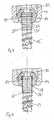
- the co-operating with the receiving part 1 screw 12has a screw shaft 13 with a threaded portion and one in the in Fig. 2 shown assembled representation connected to the screw shaft spherical segment-shaped head 14 and a tip 15.
- the screw shaft 13is tubular and has a first, the head 14 facing end 16 and an opposite end 17 on this.
- the tubular screw shaft 13has a plurality of recesses 18, which are formed diamond-shaped in the example shown. The orientation of the diamonds is such that each axis of symmetry extends parallel to the axis of symmetry of the tube. In the axial direction, the recesses 18 are arranged offset from one another such that in each case an opening between the openings of the preceding circumferentially arranged row of openings.
- a so-called bone thread 19is provided which corresponds in shape to the bone threads of conventional bone screws.
- the tubular screw shaft 13further has, in the example shown, adjacent to the first end 16 a portion 20 in which no bone thread 19 is formed and whose surface is formed substantially smooth. Furthermore, 16 are provided for screwing the front side at the first end 16 Schlitz'21 for a screwdriver.
- the tip 15comprises the actual tip portion and a shaft 22 which in the example shown has a male metric thread.
- a shaft 22which in the example shown has a male metric thread.
- On its inner wall adjacent to the second end 17 of the tubular screw shaft 13has a portion with a corresponding metric internal thread, and the tip is in the assembled state by screwing firmly connected to the tubular screw shaft.
- the head 14is formed as a flattened at its the first end 2 of the receiving part 1 end flattened ball and has a first to the longitudinal axis 4 coaxial through hole 23 having a diameter which is smaller than the diameter of the tubular Screw shaft 13.
- a coaxial second bore 24which extends from the end of the head 14 facing the second end 3 of the receiving member to a predetermined distance in the head and whose diameter is equal to the outer diameter of the tubular screw shaft 13 is in the section 20, so that the portion 20 of the screw shaft is frictionally inserted into the bore 24.
- the thus formed hollow spherical segment-shaped head 14is provided on its side opposite the flattened side with circumferentially spaced from each other and extending parallel to the longitudinal axis 4 and extending to the flattened side opposite end recesses 25 provided. This ensures that the end facing away from the first end 2 of the receiving part in the inserted state edge 26 for insertion of the screw shaft 13 is formed resiliently outwardly nachgebbar.
- a pressure element 30which is cylindrical and has an outer diameter, which is just so large that the pressure element in the first bore 5 is inserted and in this back and forth in the axial direction.
- the pressure element 30On its bottom side facing the second end 3, the pressure element 30 has a hollow spherical-segment-shaped section 31 which is symmetrical to the longitudinal axis 4 and whose radius corresponds to the radius of the head 14.
- the pressure elementfurthermore has a U-shaped recess 32 extending transversely to the longitudinal axis 4, the free legs of which extend to the first end 2 and which forms a channel for a rod 40 to be received.
- the depth of the U-shaped recessis greater than the diameter of the rod 40 to be inserted, so that in the assembled state, the legs of the Drukkelements 30 project beyond the inserted rod 40 addition.
- a coaxial bore 33connects, which serves for engagement with a screwing tool.
- screwed nut 50For fixing the position of the head 14 with the inserted screw shaft 13 relative to the receiving part 1 between the legs 8, 9 of the receiving part screwed nut 50 is provided with an external thread 51 which cooperates with the internal thread 11 of the legs.
- the nuthas at its one end slots 52 for engaging with a screwing tool.
- an internal screw 60is provided for screwing into the nut 50, which has an external thread, which cooperates with the internal thread of the nut 50.
- the internal screw 60has a recess 61 for engagement with a screwing tool.
- the screw 12is screwed into the bone or the vertebra. Then, via a syringe, bone cement or another filler material and / or agent injected into the tubular shaft. Subsequently, the receiving part 1 is placed with the second bore 6 on the shaft 13 and the head 14 is guided from the first end 2 ago on the shaft 13, so that the shaft 13 is inserted with its bone thread-free portion 20 into the bore 24 and the head the shaft in the in Fig. 2 includes manner shown. The head 14 and the shaft 13 are frictionally connected with each other.
- the pressure element 30is inserted and pressed by screwing the nut 50 on the provided with the slots 25 head 14, that this is on the one hand connected to the shaft 13 immovably or jammed and pressed simultaneously against the hollow spherical segment-shaped portion in the receiving part and thus in its rotational position is locked.
- the rod 40is still free to move. This is then fixed by screwing the inner screw 60.
- the anchoring elementthus makes it possible to treat a defective bone with an active substance and / or to stabilize it by fusion with surrounding bone material and at the same time to position and fix bone pieces or vertebrae over the rod.
- the in the FIG. 3The modification shown differs from that in the Figures 1 and 2 Example shown in that the inner wall of the bore 24 of the head 14 is formed with circumferentially provided shafts 27 and the portion 20 of the shaft 13 with corresponding shafts 27 'is provided.
- the screw shaft 13may also have other means by which it can be screwed into the bone.
- the screw shaft 13can also have an internal thread adjacent to its first end or an internal thread extending over the entire axial length.
- the shaftcan be screwed in via a head to be screwed in or another auxiliary instrument, which is removed after screwing in again.
- the screw shaft 13 adjacent to its first endis formed inside a hexagonal shape for engagement with an Allen wrench.
- the screw shaft 13is filled prior to screwing with bone material, which then grows with the bone surrounding the screw after screwing.
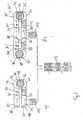
- FIGS. 5 and 6 example showndiffers from that in the Figures 1 and 2 shown substantially by the formation of the screw head 140 and its connection to the screw shaft 13th
- the screw head 140is formed spherical segment having a spherical radius which is substantially equal to the radius of the hollow spherical segment-shaped portion of the receiving part.
- the headfurther has a recess 141 for engagement with a screwdriver at its flat end facing the first end 2 of the receiving part 1.
- the screw head 140has a cylindrical neck 142 with an outer diameter that corresponds to the outer diameter of the tubular screw shaft 13. From the neck extends a shoulder 143 with an external thread with which the screw head in the tubular screw shaft 13 is screwed, which is adjacent thereto at its first end 16 on the inner wall has an internal thread 131.
- the connection of the head to the screw shaftis such that the head engages the shaft, while in the first example the head engages around the shaft.
- the screw head 140 in this examplemay conveniently have a continuous coaxial bore, which is not shown in the figures, and which serves as a channel for introducing active ingredients.
- an internal thread for screwing in the tip 15is likewise provided on the inner wall, as in the first example.
- the internal thread over the entire length of the tubular threaded shaftmay be formed, which is favorable in terms of manufacturing technology and also allows the shortening of the tubular screw shaft to a desired length.
- slots 132may be provided for engagement with a screwdriver.
- the pressure element 150has, in contrast to the pressure element 50 of the first example, only short legs 151, 152, which do not protrude laterally beyond the inserted rod 40. Otherwise, as in the first example, the pressure element has a spherical countersink 153 on its head-facing side and a coaxial bore 154.
- an internal screw 160 with an external thread 161which is the internal thread of the legs corresponds to the receiving part, and provided with a recess for engaging with a screwdriver.
- lock nut 170is provided.
- the tipis first screwed onto the screw shaft 13. Subsequently, if necessary, bone material is filled into the tubular screw shaft and the head 140 is screwed. Then, the bolt 13 screwed together from each other, tip 15 and head 140 is inserted like a known polyaxial screw in the receiving part 1 and screwed into the bone. If a cannulated head 140 is used, an agent or filler may be injected. Finally, the pressure element is used and the receiving part with the rod by screwing the inner screw 160 and the lock nut 170 firmly connected and thus fixed the angular position of the head in the receiving part.
- the screw shafthas the slits 132 for engaging with a screwdriver, first the screw shaft 13 with screwed-on tip 15 without the head 140 can be screwed. Subsequently, the active ingredient can be filled and placed the receiving part and the screw head are screwed. The connection with the rod then takes place as described above.
- the head and rod fixationis not limited to the variants described. It can be used in the first example, the head and rod fixation of the second example and vice versa. Furthermore, other embodiments, such as the provision of only one acting on the rod inner screw can be provided.
- any shape having openingsmay be provided.
- the openingsmay also extend over the entire axial length of the screw shank.
- the head 14 of the first examplemay be slit at one location throughout in the axial direction. Due to the elasticity thus generated, the head is somewhat compressible, so that it can be introduced from the second end 3 of the receiving part.
- the tip 15may be self-tapping. Further, the tip may have a coaxially extending through channel for passage of active ingredients.
- the tubular screw shaft 13may have a suitable length for the particular application, which is optionally produced by cutting a pipe section of desired length of a longer pipe section, and a diameter corresponding to the application.
- the screwcan also be designed as a pedicle screw.
- the anchoring elementmay be combined to stabilize the spine or bone generally via the rod with known anchoring elements.
- the polyaxial connection with the rod 40is not in the direction of the screw axis, as in the previous examples, but offset laterally to the screw axis.
- the anchoring elementcomprises a consisting of the tubular screw shaft 13, a tip and the spherical segment 140 head screw member and the head 140 receiving two-piece socket 70 with a screw shaft facing the lower part 71 and a screw shaft facing away upper part 72, which together comprise the rod 40.
- the lower part 71 and the upper part 72are identical and arranged in mirror image to each other. They each have a central bore 73, 74, which is provided with an internal thread and on which the other part 71, 72 opposite surface has a counterbore. Laterally of the bore 73, 74 is provided at a distance from this one to the other part 71, 72 out of the cylinder segment-shaped recess 75, 76 for holding the rod 40.
- Lower part 71 and upper part 72 of the socketare connected to each other by a screw 81, which is insertable into the internal thread of the upper part, and in the internal thread of the lower part can be screwed.
- the screw 81In its guided through the upper part 72, the screw 81 has a diameter which is smaller than the diameter of the internal thread of the upper part and has in its guided through the lower part a cooperating with the internal thread of the lower part of external thread.
- the cylinder-segment-shaped recesses 75, 76 and the spherical segment-shaped recesses 77, 78are dimensioned and arranged to each other that in the state in which the rod 40 and the head 140 are held, the lower part 71 and the upper part 72 are aligned parallel to each other and spaced from each other.
- the implantis particularly suitable for the fixation of fractures on the pelvis and long bones.
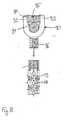
- FIG. 7bThis in Fig. 7b ) example differs from that in Fig. 7a ) example in that the socket 70 'for detecting two bars 40, 40' has a symmetrically formed in itself lower part 71 'and upper part 72'.
- the lower part 71 'and the upper part 72'are formed symmetrically to a plane defined by the center line of the rods 40, 40 'and the center of the spherical segment-shaped head 140 of the screw and each have two holes 73, 73' and 74, 74 ' , two cylinder segment-shaped recesses 75, 75 'and 76, 76' on.
- the anchoring elementconsists of a screw element which is formed by the tubular screw shaft 13 with a tip connected to the latter, and of a screw element monoaxially connectable receiving part 90 for receiving a rod 40.
- the receiving part 90is formed substantially cylindrical and has a recess 91 of U-shaped cross section, which is just sized so large that the rod 40 is inserted and fits into the bottom of the recess.
- two free legs 92, 93are formed. Adjacent to the free end, the legs 92, 93 on an internal thread 94, which cooperates with a corresponding external thread of a screwed between the legs of the inner screw 95 for fixing the rod 40.
- the receiving part 90has a threaded shaft 96 for screwing into the tubular shaft 13.
- the anchoring elementis first fully assembled, with the tubular shaft filled with active ingredients or bone material when required. Subsequently, the anchoring element is screwed into the bone like a known monoaxial screw. Then the connection via the rod to one or more other anchoring elements. In the correct position, the rod is then fixed over the inner screw.
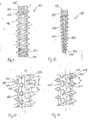
- the recesses 18are partially arranged to break the helical tip of the bone thread. As a result, teeth or sharp edges are formed on the bone thread, which have a milling effect when screwed into the bone. However, for certain applications, smooth screwing is desired or required.
- the tubular screw shaft 113consists of a cylindrical tube having a first end 114 and a second end 115 opposite thereto.
- the tubehas, as in the examples of FIGS. 1 to 8 on its outer wall a bone threaded portion 116 with a bone thread for screwing into the bone.
- the bone threadis formed as a self-tapping thread and has in a known manner thread flanks 117, a spiral tip 118, a thread base 119 with a width B and a pitch P.
- the wall of the tubular shafthas a plurality of recesses 120 with a circular Cross-section on.
- the recesses 120are arranged so that their center lies in the thread root 119 and the diameter D of each recess 120 is smaller than the pitch P and in particular not greater than the width B of the thread base, so that in the in FIGS. 9 and 10 illustrated example, the recesses 120 are completely in the thread root 119 and do not extend into the flanks 117.
- Fig. 9has the tubular shaft 113 adjacent to the first end 115 a bone thread-free portion 121 with a smooth outer wall, in which no recesses are formed. Further, in the example shown, adjacent to the first end 114 and adjacent to the second end 115 of the tube, there is formed a female threaded portion 122 which serves to connect to the headed and female part, as described in the previous embodiments.
- FIG. 11 shown further modified examplediffers from that in the FIGS. 9 and 10 Example shown in that the diameter D 'of the recess 120' is greater than the width B of the thread root 119, so that the recesses 120 'hineinerumblen into the flanks 117 of the bone thread, but without breaking the coil tip 118.
- all or a part of the recesses 120, 120 'are provided on the outside of the wall with a countersink, which forms a surface roughness, which facilitates an ingrowth or growth.
- the diameter of this countersink in the screw axis directionis smaller than the thread pitch P, so that the helical tip 118 is intact.
- the recessesare oval or diamond-shaped. It is crucial that they are arranged in the thread root and that their dimensions are such that the cutting tip of the bone thread is not damaged. Furthermore, it is not necessary to provide recesses in each thread.
- the bone thread portion 116extends over the entire length of the shaft 113.
- the internal thread 122may also extend over the entire length.
- the internal thread 122may also be provided only at one end in a section or not at all. The connection with the other parts of the anchoring element takes place in the case that no internal thread is provided, e.g. over snug fit.
- the tubular screw shaft 125is not formed as a whole cylindrical, but has a conical bone thread portion 126 which tapers in the direction of the end 127 to be connected to the tip. Adjacent to the conical bone thread portion 126 extends on both sides in each case to the opposite ends 127, 128 each have a cylindrical portion 129, 130 with an internal thread for connection to the tip at one end or with a head or a receiving part, as described above, on other end.
- the cylindrical portion 129 to be connected to the tipis not provided, but the free end of the conical bone thread portion 126 acts as a tip itself.
Landscapes
- Health & Medical Sciences (AREA)
- Orthopedic Medicine & Surgery (AREA)
- Surgery (AREA)
- Life Sciences & Earth Sciences (AREA)
- Heart & Thoracic Surgery (AREA)
- Veterinary Medicine (AREA)
- Engineering & Computer Science (AREA)
- Biomedical Technology (AREA)
- Nuclear Medicine, Radiotherapy & Molecular Imaging (AREA)
- Medical Informatics (AREA)
- Molecular Biology (AREA)
- Animal Behavior & Ethology (AREA)
- General Health & Medical Sciences (AREA)
- Public Health (AREA)
- Neurology (AREA)
- Dentistry (AREA)
- Oral & Maxillofacial Surgery (AREA)
- Surgical Instruments (AREA)
- Prostheses (AREA)
Description
Translated fromGermanDie Erfindung betrifft ein Verankerungselement mit einer einen Schaft mit einem Knochengewindeabschnitt und einen Kopf aufweisenden Schraube und einem Aufnahmeteil zum Verbinden der Schraube mit einem Stab nach dem Oberbegriff des Patentanspruches 1. Ein solches Verankerungselement wird insbesondere in der Wirbelsäulenchirurgie, aber auch in der Unfallchirurgie eingesetzt.The invention relates to an anchoring element with a shaft having a bone threaded portion and a head having screw and a receiving part for connecting the screw with a rod according to the preamble of
Ein Verankerungselement ist zum Beispiel aus der
Eine bekannte Behandlungsmethode zum Behandeln von Knochendefekten, insbesondere von osteoporotischen Frakturen, beinhaltet das Einspritzen von Knochenzement und/oder von medikamentösen Wirkstoffen, insbesondere von wachstumsfördernden Stoffen, in den Knochen. Insbesondere im Bereich der Wirbelsäule erfordert dies eine genaue Positionierung des einzuspritzenden Materials im Wirbel. Ferner ist es in den vielen Fällen erforderlich, die defekten Wirbel zusätzlich zu stabilisieren bzw. relativ zueinander zu fixieren.One known method of treatment for treating bone defects, particularly osteoporotic fractures, involves injecting bone cement and / or drug Active ingredients, in particular of growth-promoting substances, in the bones. Especially in the area of the spine, this requires an exact positioning of the material to be injected in the vortex. Furthermore, in many cases it is necessary to additionally stabilize or fix the defective vertebrae relative to one another.
Die
Der Oberbegriff des Anspruchs 1 basiert auf diesem Verankerungselement.The preamble of
Aus der
Aufgabe der Erfindung ist es, ein Verankerungselement der eingangs beschriebenen Art so zu verbessern, daß es insbesondere bei der Behandlung von osteoporotischen Frakturen einsetzbar ist.The object of the invention is to improve an anchoring element of the type described above so that it can be used in particular in the treatment of osteoporotic fractures.
Diese Aufgabe wird durch das in Patentanspruch 1 gekennzeichnete Verankerungselement gelöst. Dadurch wird es möglich, daß die Knochenschraube mit dem umgebenden Knochenmaterial fusionieren kann, sowie gleichzeitig Knochenabschnitte oder Wirbel relativ zueinander positioniert und fixiert werden können. Ferner kann ein in den Knochen einzubringendes Material präzise an die erforderliche Stelle eingebracht werden.This object is achieved by the characterized in
Weiterbildungen der Erfindung sind in den Unteransprüchen gekennzeichnet.Further developments of the invention are characterized in the subclaims.
Weitere Merkmale und Zweckmäßigkeiten der Erfindung ergeben sich aus der Beschreibung von Beispielen, die keine Ausführungsform der Erfindung sind, anhand der Figuren.Further features and advantages of the invention will become apparent from the description of examples, which are not an embodiment of the invention, with reference to the figures.
Von den Figuren zeigen:
- Fig. 1
- eine Explosionsdarstellung eines ersten Verankerungselements;
- Fig. 2
- eine Seitenansicht des Verankerungselements von
Fig. 1 in geschnittener Darstellung; - Fig.3
- einen Ausschnitt einer Abwandlung des Verankerungselements nach
Fig. 1 in geschnittener Darstellung; - Fig. 4
- einen Ausschnitt einer weiteren Abwandlung des Verankerungselements in geschnittener Darstellung;
- Fig. 5
- eine Explosionsdarstellung eines zweiten Verankerungselements;
- Fig. 6
- eine Seitenansicht des zweiten Verankerungselements in geschnittener Darstellung.
- Fig. 7a)
- ein weiteres Verankerungselement;
- Fig. 7b)
- ein weiteres Verankerungselement;
- Fig. 8
- ein weiteres Verankerungselement;
- Fig. 9
- eine Abwandlung;
- Fig. 10
- eine vergrößerte teilgeschnittene Darstellung der Abwandlung von
Fig. 9 ; - Fig. 11
- eine weitere Abwandlung in vergrößerter teilgeschnittener Darstellung; und
- Fig. 12
- ein weitere Abwandlung.
- Fig. 1
- an exploded view of a first anchoring element;
- Fig. 2
- a side view of the anchoring element of
Fig. 1 in a sectional view; - Figure 3
- a section of a modification of the anchoring element after
Fig. 1 in a sectional view; - Fig. 4
- a section of a further modification of the anchoring element in a sectional view;
- Fig. 5
- an exploded view of a second anchoring element;
- Fig. 6
- a side view of the second anchoring element in a sectional view.
- Fig. 7a)
- another anchoring element;
- Fig. 7b)
- another anchoring element;
- Fig. 8
- another anchoring element;
- Fig. 9
- a modification;
- Fig. 10
- an enlarged partial sectional view of the modification of
Fig. 9 ; - Fig. 11
- a further modification in an enlarged partial sectional view; and
- Fig. 12
- another variation.
Bei den in dem
Das Aufnahmeteil 1 weist ausgehend von dem ersten Ende 2 eine sich senkrecht zu Längsachse 3 erstreckende U-förmige Ausnehmung 7 auf mit zwei zum ersten Ende 2 hin endenden freien Schenkeln 8, 9. Angrenzend an das erste Ende 2 weisen die Schenkel einen Innengewinde 10 auf. Das Innengewinde ist zum Beispiel als Flachgewinde mit Gewindeflanken, die sich jeweils unter einem Winkel von 90° zur Symmetrieachse 4 erstrecken, ausgebildet. Der Grund der U-förmigen Ausnehmung erstreckt sich bis zu einem vorgegebenen Abstand von dem zweiten Ende 3 hin.The receiving
Die mit dem Aufnahmeteil 1 zusammenwirkende Schraube 12 weist einen Schraubenschaft 13 mit einem Gewindeabschnitt und einen in der in
Der Schraubenschaft 13 ist rohrförmig ausgebildet und weist ein erstes, dem Kopf 14 zugewandtes Ende 16 und ein diesem gegenüberliegendes Ende 17 auf. In seiner Wandung weist der rohrförmige Schraubenschaft 13 eine Vielzahl von Ausnehmungen 18 auf, die in dem gezeigten Beispiel rautenförmig ausgebildet sind. Dabei erfolgt die Ausrichtung der Rauten derart, daß jeweils eine Symmetrieachse sich parallel zur Symmetrieachse des Rohres erstreckt. In axialer Richtung sind die Ausnehmungen 18 gegeneinander versetzt derart angeordnet, daß jeweils eine Öffnung zwischen den Öffnungen der vorhergehenden in Umfangsrichtung angeordneten Reihe von Öffnungen ist. Auf der Außenwandung ist in einem Bereich, der sich vom zweiten Ende 17 des Schraubenschafts 13 bis wenigstens zu einem vorbestimmten Abstand von dem ersten Ende 16 hin erstreckt, ein sogenanntes Knochengewinde 19 vorgesehen, welches in seiner Form den Knochengewinden üblicher Knochenschrauben entspricht. Der rohrförmige Schraubenschaft 13 weist ferner in dem gezeigten Beispiel angrenzend an das erste Ende 16 einen Abschnitt 20 auf, in dem kein Knochengewinde 19 gebildet ist und dessen Oberfläche im wesentlichen glatt ausgebildet ist. Ferner sind zum Einschrauben stirnseitig an dem ersten Ende 16 Schlitze'21 für einen Schraubendreher vorgesehen.The
Die Spitze 15 umfaßt den eigentlichen Spitzenteil und einen Schaft 22, der in dem gezeigten Beispiel ein metrisches Außengewinde aufweist. An seiner Innenwandung angrenzend an das zweite Ende 17 weist der rohrförmige Schraubenschaft 13 ein Abschnitt mit einem entsprechenden metrischen Innengewinde auf, und die Spitze ist in montiertem Zustand durch Einschrauben fest mit dem rohrförmigen Schraubenschaft verbunden.The
Wie am besten aus
Es ist ferner ein Druckelement 30 vorgesehen, welches zylindrisch ausgebildet ist und einen Außendurchmesser aufweist, der gerade so groß ist, daß das Druckelement in die erste Bohrung 5 einführbar und in dieser in Axialrichtung hin- und herbewegbar ist. Auf seiner dem zweiten Ende 3 zugewandten Unterseite weist das Druckelement 30 einen zur Längsachse 4 symmetrisch ausgebildeten hohlkugelsegmentförmigen Abschnitt 31 auf, dessen Radius dem Radius des Kopfes 14 entspricht. Das Druckelement weist ferner eine sich quer zur Längsachse 4 erstreckende U-förmige Ausnehmung 32 auf, deren freie Schenkel sich zum ersten Ende 2 hin erstrecken und die einen Kanal für einen aufzunehmender Stab 40 bildet. Die Tiefe der U-förmigen Ausnehmung ist größer, als der Durchmesser des einzusetzenden Stabes 40, so daß in montiertem Zustand die Schenkel des Drukkelements 30 über den eingelegten Stab 40 hinaus hervorstehen. Am Grund der U-förmigen Ausnehmung 32 schließt sich eine koaxiale Bohrung 33 an, die zum Eingreifen mit einem Schraubwerkzeug dient.It is further provided a
Zum Fixieren der Stellung des Kopfes 14 mit dem eingesetzten Schraubenschaft 13 relativ zu dem Aufnahmeteil 1 ist eine zwischen die Schenkel 8, 9 des Aufnahmeteils einschraubbare Mutter 50 mit einem Außengewinde 51 vorgesehen, welches mit dem Innengewinde 11 der Schenkel zusammenwirkt. Die Mutter weist an ihrem einen Ende Schlitze 52 zum Ineingriffbringen mit einem Schraubwerkzeug auf.For fixing the position of the
Ferner ist eine Innenschraube 60 zum Einschrauben in die Mutter 50 vorgesehen, die ein Außengewinde aufweist, welches mit dem Innengewinde der Mutter 50 zusammenwirkt. Die Innenschraube 60 weist eine Ausnehmung 61 zum Ineingriffbringen mit einem Schraubwerkzeug auf.Further, an
Im Betrieb wird zunächst die Schraube 12 in den Knochen bzw. dem Wirbel eingeschraubt. Dann wird über eine Spritze Knochenzement oder ein anderes Füllmaterial und/oder ein Wirkstoff in den rohrförmigen Schaft eingespritzt. Anschließend wird das Aufnahmeteil 1 mit der zweiten Bohrung 6 auf den Schaft 13 aufgesetzt und der Kopf 14 von dem ersten Ende 2 her auf den Schaft 13 geführt, so daß der Schaft 13 mit seinem knochengewindefreien Abschnitt 20 in die Bohrung 24 eingeführt wird und der Kopf den Schaft in der in
Die in der
Bei der in
Der Schraubenschaft 13 kann auch andere Mittel aufweisen über die er in den Knochen einschraubbar ist. Beispielsweise kann der Schraubenschaft 13 ein Innengewinde auch angrenzend an sein erstes Ende oder ein sich über die gesamte axiale Länge erstreckendes Innengewinde aufweisen. In diesem Fall kann der Schaft über einen einzuschraubende Kopf oder ein anderes Hilfsinstrument, welches nach dem Einschrauben wieder entfernt wird, eingeschraubt werden. Alternativ ist es möglich, daß der Schraubenschaft 13 angrenzend an sein erstes Ende innen sechskantförmig zum Eingreifen mit einem Inbusschlüssel ausgebildet ist.The
Es ist auch möglich, daß der Schraubenschaft 13 vor dem Einschrauben mit Knochenmaterial gefüllt wird, welches dann mit dem die Schraube umgebenden Knochenmaterial nach dem Einschrauben verwächst.It is also possible that the
Das in den
Der Schraubenkopf 140 ist kugelsegmentförmig ausgebildet mit einem Kugelradius, der im wesentlichen gleich dem Radius des hohlkugelsegmentförmigen Abschnitts des Aufnahmeteils ist. Der Kopf weist ferner an seinem zu dem ersten Ende 2 des Aufnahmeteils 1 hin zu richtenden abgeflachten Ende eine Ausnehmung 141 zum Ineingriffbringen mit einem Schraubendreher auf. An seinem gegenüberliegenden Ende besitzt der Schraubenkopf 140 einen zylindrischen Hals 142 mit einem Außendurchmesser, der dem Außendurchmesser des rohrförmigen Schraubenschafts 13 entspricht. Von dem Hals erstreckt sich ein Ansatz 143 mit einem Außengewinde mit dem der Schraubenkopf in den rohrförmigen Schraubenschaft 13 einschraubbar ist, welcher hierzu angrenzend an sein erstes Ende 16 an der Innenwandung ein Innengewinde 131 aufweist. Somit erfolgt im Gegensatz zu der ersten Ausführungsform die Verbindung des Kopfes mit dem Schraubenschaft derart, daß der Kopf in den Schaft eingreift, während bei dem ersten Beispiel der Kopf den Schaft umgreift.The
Der Schraubenkopf 140 in dieser Beispiel kann zweckmäßigerweise eine durchgehende koaxiale Bohrung aufweisen, die in den Figuren nicht dargestellt ist, und welche als Kanal zu Einführen von Wirkstoffen dient.The
Angrenzend an das zweite Ende 17 des rohrförmigen Schraubenschaftes 13 ist wie bei dem ersten Beispiel an der Innenwandung ebenfalls ein Innengewinde zum Einschrauben der Spitze 15 vorgesehen. Wie auch schon bei der ersten Ausführungsform kann das Innengewinde über die gesamte Länge des rohrförmigen Gewindeschafts ausgebildet sein, was herstellungstechnisch günstig ist und außerdem das Kürzen des rohrförmigen Schraubenschafts auf eine gewünschte Länge erlaubt. An dem ersten Ende des Schraubenschaftes 13 können Schlitze 132 zum Eingreifen mit einem Schraubendreher vorgesehen sein.Adjacent to the
In dem dargestellten Beispiel ist eine Variante der bei dem ersten Beispiel gezeigten Kopf- und Stabfixierung dargestellt. Das Druckelement 150 weist im Gegensatz zu dem Druckelement 50 des ersten Beispiels nur kurze Schenkel 151, 152 auf, die nicht seitlich über den eingelegten Stab 40 überstehen. Ansonsten weist das Druckelement wie bei der ersten Beispiel eine sphärische Ansenkung 153 an seiner dem Kopf zugewandten Seite und eine koaxiale Bohrung 154 auf.In the illustrated example, a variant of the head and rod fixation shown in the first example is shown. The
Zum Fixieren von Kopf und Stab ist eine Innenschraube 160 mit einem Außengewinde 161, welches dem Innengewinde der Schenkel des Aufnahmeteils entspricht, und mit einer Ausnehmung zum Ineingriffbringen mit einem Schraubendreher vorgesehen. Zur Sicherung der Fixierung ist eine auf das Aufnahmeteil 1 aufschraubbare Sicherungsmutter 170 vorgesehen.To fix the head and rod is an
Im Betrieb wird zuerst die Spitze auf den Schraubenschaft 13 aufgeschraubt. Anschließend wird, falls erforderlich, Knochenmaterial in den rohrförmigen Schraubenschaft eingefüllt und der Kopf 140 aufgeschraubt. Dann wird die aus miteinander verschraubten Schaft 13, Spitze 15 und Kopf 140 bestehende Schraube wie eine bekannte Polyaxialschraube in das Aufnahmeteil 1 eingeführt und in den Knochen eingeschraubt. Falls ein kanulierter Kopf 140 verwendet wird, kann ein Wirkstoff oder ein Füllmaterial eingespritzt werden. Schließlich wird das Druckelement eingesetzt und das Aufnahmeteil mit dem Stab durch Einschrauben der Innenschraube 160 und der Sicherungsmutter 170 fest verbunden und somit die Winkelstellung des Kopfs in dem Aufnahmeteil fixiert.In operation, the tip is first screwed onto the
Alternativ kann auch, wenn der Schraubenschaft die Schlitze 132 zum Eingreifen mit einem Schraubendreher aufweist, zuerst der Schraubenschaft 13 mit aufgeschraubter Spitze 15 ohne den Kopf 140 eingeschraubt werden. Anschließend kann der Wirkstoff eingefüllt werden und das Aufnahmeteil aufgesetzt und der Schraubenkopf aufgeschraubt werden. Die Verbindung mit dem Stab erfolgt dann wie zuvor beschrieben.Alternatively, even if the screw shaft has the slits 132 for engaging with a screwdriver, first the
Abwandlungen der beschriebenen Beispiel sind möglich. Zum einen ist die Kopf- und Stabfixierung nicht auf die beschriebenen Varianten beschränkt. Es kann bei dem ersten Beispiel auch die Kopf- und Stabfixierung des zweiten Beispiels verwendet werden und umgekehrt. Ferner können auch andere Ausbildungen, wie z.B. das Vorsehen von lediglich einer auf den Stab einwirkenden Innenschraube vorgesehen sein.Modifications of the example described are possible. First, the head and rod fixation is not limited to the variants described. It can be used in the first example, the head and rod fixation of the second example and vice versa. Furthermore, other embodiments, such as the provision of only one acting on the rod inner screw can be provided.
Anstelle der rautenförmigen Öffnungen im Schraubenschaft können auch kreisförmige, ovale oder andere, eine beliebige Form aufweisende Öffnungen vorgesehen sein. Die Öffnungen können sich ferner über die gesamte axiale Länge des Schraubenschaftes erstrecken.Instead of the diamond-shaped openings in the screw shaft and circular, oval or other, any shape having openings may be provided. The openings may also extend over the entire axial length of the screw shank.
Der Kopf 14 des ersten Beispiels kann an einer Stelle durchgehend in axialer Richtung geschlitzt sein. Durch die somit erzeugte Elastizität ist der Kopf etwas zusammendrückbar, so daß er von dem zweiten Ende 3 des Aufnahmeteils her einführbar ist.The
Die Spitze 15 kann selbstschneidend ausgebildet sein. Ferner kann die Spitze einen koaxial verlaufenden durchgehenden Kanal zum Hindurchleiten von Wirkstoffen haben.The
Der rohrförmige Schraubenschaft 13 kann eine für die jeweilige Anwendung geeignete Länge aufweisen, die gegebenenfalls durch Abschneiden eines Rohrstücks mit gewünschter Länge von einem längeren Rohrstück erzeugt wird, sowie einen der Anwendung entsprechenden Durchmesser. Insbesondere kann die Schraube auch als Pedikelschraube ausgebildet sein.The
Das Verankerungselement kann zur Stabilisierung der Wirbelsäule oder von Knochen allgemein über den Stab mit bekannten Verankerungselementen kombiniert werden.The anchoring element may be combined to stabilize the spine or bone generally via the rod with known anchoring elements.
In dem in den
Das Verankerungselement gemäß
Unterteil 71 und Oberteil 72 der Fassung sind durch eine Schraube 81 miteinander verbunden, die in das Innengewinde des Oberteils einführbar ist, und in das Innengewinde des Unterteils einschraubbar ist. In ihrem durch das Oberteil 72 geführten Teil hat die Schraube 81 einen Durchmesser, der kleiner ist, als der Durchmesser des Innengewindes des Oberteils und weist in ihrem durch das Unterteil geführten Teil ein mit dem Innengewinde des Unterteils zusammenwirkendes Außengewinde auf. Die zylindersegmentförmigen Ausnehmungen 75, 76 und die kugelsegmentförmigen Ausnehmungen 77, 78 sind so dimensioniert und so zueinander angeordnet, daß in dem Zustand in dem der Stab 40 und der Kopf 140 gehalten sind, das Unterteil 71 und das Oberteil 72 parallel zueinander ausgerichtet sind und einen Abstand voneinander besitzen.
Im Betrieb wird erst das Schraubenelement zusammengesetzt indem Spitze und Kopf 140 an den Schaft geschraubt werden. Das Oberteil und das Unterteil der Fassung sind durch Losedrehen der Schraube 81 um 90 Grad gegeneinander verdreht, so daß das Schraubenelement in das Unterteil einführbar ist. Das Schraubenelement wird eingeführt, bis sein Kopf 140 in der kugelsegmentförmigen Ausnehmung 77 des Unterteils 71 anliegt. Anschließend wird es in den Knochen eingeschraubt. Dann wird der Stab 40 aufgenommen und das Oberteil 72 um 90 Grad zum Fassen des Stabs gedreht. Nach erfolgter Justierung der Winkelstellung des Schraubenkopfs 140 in der Fassung und der Position des Stabs erfolgt ein Fixieren durch Festziehen der Schraube 81.In operation, only the screw element is assembled by screwing tip and
Das Implantat ist insbesondere für die Fixierung von Frakturen am Becken und an Röhrenknochen geeignet.The implant is particularly suitable for the fixation of fractures on the pelvis and long bones.
Das in
Bei dem in
Im Betrieb wird das Verankerungselement vorzugsweise zuerst vollständig zusammengesetzt, wobei der rohrförmige Schaft wenn es erforderlich ist, mit Wirkstoffen oder Knochenmaterial gefüllt ist. Anschließend wird das Verankerungselement wie eine bekannte Monoaxialschraube in den Knochen eingeschraubt. Dann erfolgt die Verbindung über den Stab zu einem oder mehreren anderen Verankerungselementen. In korrekter Position wird anschließend der Stab über die Innenschraube fixiert.In operation, preferably, the anchoring element is first fully assembled, with the tubular shaft filled with active ingredients or bone material when required. Subsequently, the anchoring element is screwed into the bone like a known monoaxial screw. Then the connection via the rod to one or more other anchoring elements. In the correct position, the rod is then fixed over the inner screw.
Bei den in den
Für derartige Anwendungen ist eine in den
Wie insbesondere aus
Das in
In einer weiteren, nicht dargestellten Abwandlung sind alle oder ein Teil der Ausnehmungen 120, 120' an der Außenseite der Wandung mit einer Ansenkung versehen, die eine Oberflächenrauhigkeit bildet, welche ein Ein- bzw. Anwachsen erleichtert. Der Durchmesser dieser Ansenkung in Schraubenachsrichtung ist jedoch kleiner als die Gewindesteigung P, so daß die Wendelspitze 118 unversehrt ist.In a further modification, not shown, all or a part of the
In einer weiteren Abwandlung sind die Ausnehmungen oval oder rautenförmig. Entscheidend ist, daß sie im Gewindegrund angeordnet sind und daß ihre Abmessungen so sind, daß die Schneidspitze des Knochengewindes nicht verletzt wird. Es müssen ferner nicht in jedem Gewindegang Ausnehmungen vorgesehen sein.In a further modification, the recesses are oval or diamond-shaped. It is crucial that they are arranged in the thread root and that their dimensions are such that the cutting tip of the bone thread is not damaged. Furthermore, it is not necessary to provide recesses in each thread.
In einer weiteren Abwandlung erstreckt sich der Knochengewindeabschnitt 116 über die gesamte Länge des Schafts 113. Das Innengewinde 122 kann sich ebenfalls über die gesamte Länge erstrecken. Alternativ kann das Innengewinde 122 auch nur an einem Ende in einem Abschnitt oder gar nicht vorgesehen sein. Die Verbindung mit den weiteren teilen des Verankerungselement erfolgt im Fall, daß kein Innengewinde vorgesehen ist, z.B. über Paßsitz.In a further modification, the
In einer in
In einer Abwandlung ist der mit der Spitze zu verbindende zylindrische Abschnitt 129 nicht vorgesehen, sondern das freie Ende des konischen Knochengewindeabschnitts 126 wirkt selbst als Spitze.In a modification, the
In den in
Claims (17)
- Anchoring element comprising a screw (12) having a shank (13) with a bone thread portion and a head (14; 140), and comprising a receiving part (1) for connecting the screw with a rod-shaped element (40), the screw and the receiving part being monoaxially connected to one another, and wherein the shank (13) of the screw is of tubular design and its wall has a plurality of recesses (18),
characterized in that the receiving part (70, 70') is designed in such a manner that the rod-shaped element (40, 40') is held offset with respect to the screw axis. - Anchoring element according to claim 1, wherein the shank (13) and the head (14; 140) are designed as separate parts.
- Anchoring element according to claim 2, wherein the shank (13) comprises an inner thread portion at its end (16) directed toward the head, and the head (140) has a portion with a corresponding outer thread (143) so that the head can be screwed into the shank.
- Anchoring element according to claim 2, wherein the head (14), at its end directed toward the shank, has a recess (24) in which the shank (13) is held.
- Anchoring element according to claim 4, wherein the head (14) has a resiliently yielding edge (25, 26) on its side directed toward the shank (13).
- Anchoring element according to claim 4 or 5, wherein the shank (13), adjacent to its end directed toward the head (14) has a bone thread-free portion (20).
- Anchoring element according to claim 6, wherein the bone thread-free portion (20) substantially has a smooth surface.
- Anchoring element according to claim 6, wherein the bone thread-free portion (20) has a metric outer thread (28') which cooperates with a corresponding inner thread (28) on the wall of the recess (24).
- Anchoring element according to claim 6, wherein the bone thread-free portion (20) has a corrugated outer surface (27') which cooperates with a corrugated wall (27) of the recess (24).
- Bone anchoring element according to one of claims 1 to 9, wherein the head has a channel extending through it.
- Anchoring element according to one of claims 1 to 10, wherein the tip of the screw is a separate element which can be screwed into an inner thread portion of the shank.
- Anchoring element according to one of claims 1 to 11, wherein the head of the screw and the receiving part (90) are designed as one piece, whereby a monoaxial connection is established.
- Anchoring element according to one of claims 1 to 12, wherein some of the recesses (18) protrude into the bone thread in such a way that the helix crest is interrupted.
- Anchoring element according to one of claims 1 to 12, wherein the recesses (120, 120') are arranged in the thread root (119) of the bone thread and are so dimensioned that the helix crest (118) of the bone thread is left intact.
- Anchoring element according to one of claims 1 to 14, wherein the tubular shank has a conical bone thread portion (126).
- Anchoring element according to one of claims 1 to 15, wherein the shank is a tubular shank element with a bone thread portion (13) and with recesses (18) in the wall in the bone thread portion, which is at one end (17) formed so as to receive a tip and which comprises at the opposite end (16) means (21) for engagement with a screw driver for screwing in the shank element into the bone.
- Anchoring element according to claim 16, wherein the means for engagement with a screw driver are slits (21) on the front face.
Applications Claiming Priority (2)
| Application Number | Priority Date | Filing Date | Title |
|---|---|---|---|
| DE10246177ADE10246177A1 (en) | 2002-10-02 | 2002-10-02 | Anchor element consists of screw with head, bone-thread section on shank and holder joining rod-shaped part to screw. with cavities in wall, and thread-free end of shank |
| EP02795258AEP1443866B1 (en) | 2002-10-02 | 2002-12-20 | Bone anchoring element |
Related Parent Applications (1)
| Application Number | Title | Priority Date | Filing Date |
|---|---|---|---|
| EP02795258ADivisionEP1443866B1 (en) | 2002-10-02 | 2002-12-20 | Bone anchoring element |
Publications (2)
| Publication Number | Publication Date |
|---|---|
| EP1681024A1 EP1681024A1 (en) | 2006-07-19 |
| EP1681024B1true EP1681024B1 (en) | 2008-06-25 |
Family
ID=37252235
Family Applications (2)
| Application Number | Title | Priority Date | Filing Date |
|---|---|---|---|
| EP02795258AExpired - LifetimeEP1443866B1 (en) | 2002-10-02 | 2002-12-20 | Bone anchoring element |
| EP06005740AExpired - LifetimeEP1681024B1 (en) | 2002-10-02 | 2002-12-20 | Bone anchor element |
Family Applications Before (1)
| Application Number | Title | Priority Date | Filing Date |
|---|---|---|---|
| EP02795258AExpired - LifetimeEP1443866B1 (en) | 2002-10-02 | 2002-12-20 | Bone anchoring element |
Country Status (7)
| Country | Link |
|---|---|
| US (1) | US9848892B2 (en) |
| EP (2) | EP1443866B1 (en) |
| JP (2) | JP4437086B2 (en) |
| KR (1) | KR100996240B1 (en) |
| AU (1) | AU2002360070A1 (en) |
| DE (3) | DE10246177A1 (en) |
| WO (1) | WO2004032774A1 (en) |
Families Citing this family (229)
| Publication number | Priority date | Publication date | Assignee | Title |
|---|---|---|---|---|
| US20060025771A1 (en)* | 2000-08-23 | 2006-02-02 | Jackson Roger P | Helical reverse angle guide and advancement structure with break-off extensions |
| US7837716B2 (en)* | 2000-08-23 | 2010-11-23 | Jackson Roger P | Threadform for medical implant closure |
| US20060083603A1 (en)* | 2000-08-23 | 2006-04-20 | Jackson Roger P | Reverse angled threadform with anti-splay clearance |
| US7833250B2 (en) | 2004-11-10 | 2010-11-16 | Jackson Roger P | Polyaxial bone screw with helically wound capture connection |
| US8377100B2 (en)* | 2000-12-08 | 2013-02-19 | Roger P. Jackson | Closure for open-headed medical implant |
| US6726689B2 (en)* | 2002-09-06 | 2004-04-27 | Roger P. Jackson | Helical interlocking mating guide and advancement structure |
| US10258382B2 (en) | 2007-01-18 | 2019-04-16 | Roger P. Jackson | Rod-cord dynamic connection assemblies with slidable bone anchor attachment members along the cord |
| US8353932B2 (en) | 2005-09-30 | 2013-01-15 | Jackson Roger P | Polyaxial bone anchor assembly with one-piece closure, pressure insert and plastic elongate member |
| US8292926B2 (en) | 2005-09-30 | 2012-10-23 | Jackson Roger P | Dynamic stabilization connecting member with elastic core and outer sleeve |
| US7862587B2 (en) | 2004-02-27 | 2011-01-04 | Jackson Roger P | Dynamic stabilization assemblies, tool set and method |
| US10729469B2 (en) | 2006-01-09 | 2020-08-04 | Roger P. Jackson | Flexible spinal stabilization assembly with spacer having off-axis core member |
| US6740086B2 (en) | 2002-04-18 | 2004-05-25 | Spinal Innovations, Llc | Screw and rod fixation assembly and device |
| US8876868B2 (en)* | 2002-09-06 | 2014-11-04 | Roger P. Jackson | Helical guide and advancement flange with radially loaded lip |
| WO2006052796A2 (en) | 2004-11-10 | 2006-05-18 | Jackson Roger P | Helical guide and advancement flange with break-off extensions |
| US8282673B2 (en)* | 2002-09-06 | 2012-10-09 | Jackson Roger P | Anti-splay medical implant closure with multi-surface removal aperture |
| US8257402B2 (en)* | 2002-09-06 | 2012-09-04 | Jackson Roger P | Closure for rod receiving orthopedic implant having left handed thread removal |
| US20060009773A1 (en)* | 2002-09-06 | 2006-01-12 | Jackson Roger P | Helical interlocking mating guide and advancement structure |
| DE10260222B4 (en)* | 2002-12-20 | 2008-01-03 | Biedermann Motech Gmbh | Tubular element for an implant and implant to be used in spine or bone surgery with such an element |
| US8540753B2 (en) | 2003-04-09 | 2013-09-24 | Roger P. Jackson | Polyaxial bone screw with uploaded threaded shank and method of assembly and use |
| US7621918B2 (en) | 2004-11-23 | 2009-11-24 | Jackson Roger P | Spinal fixation tool set and method |
| US6716214B1 (en) | 2003-06-18 | 2004-04-06 | Roger P. Jackson | Polyaxial bone screw with spline capture connection |
| US7354442B2 (en)* | 2003-05-05 | 2008-04-08 | Warsaw Orthopedic, Inc. | Bone anchor and methods of using the same |
| US7377923B2 (en) | 2003-05-22 | 2008-05-27 | Alphatec Spine, Inc. | Variable angle spinal screw assembly |
| US8366753B2 (en)* | 2003-06-18 | 2013-02-05 | Jackson Roger P | Polyaxial bone screw assembly with fixed retaining structure |
| US7776067B2 (en)* | 2005-05-27 | 2010-08-17 | Jackson Roger P | Polyaxial bone screw with shank articulation pressure insert and method |
| US8926670B2 (en) | 2003-06-18 | 2015-01-06 | Roger P. Jackson | Polyaxial bone screw assembly |
| US8257398B2 (en) | 2003-06-18 | 2012-09-04 | Jackson Roger P | Polyaxial bone screw with cam capture |
| US7766915B2 (en) | 2004-02-27 | 2010-08-03 | Jackson Roger P | Dynamic fixation assemblies with inner core and outer coil-like member |
| US8137386B2 (en) | 2003-08-28 | 2012-03-20 | Jackson Roger P | Polyaxial bone screw apparatus |
| US7967850B2 (en) | 2003-06-18 | 2011-06-28 | Jackson Roger P | Polyaxial bone anchor with helical capture connection, insert and dual locking assembly |
| US8092500B2 (en) | 2007-05-01 | 2012-01-10 | Jackson Roger P | Dynamic stabilization connecting member with floating core, compression spacer and over-mold |
| US8398682B2 (en) | 2003-06-18 | 2013-03-19 | Roger P. Jackson | Polyaxial bone screw assembly |
| US8377102B2 (en) | 2003-06-18 | 2013-02-19 | Roger P. Jackson | Polyaxial bone anchor with spline capture connection and lower pressure insert |
| US11419642B2 (en) | 2003-12-16 | 2022-08-23 | Medos International Sarl | Percutaneous access devices and bone anchor assemblies |
| US7179261B2 (en) | 2003-12-16 | 2007-02-20 | Depuy Spine, Inc. | Percutaneous access devices and bone anchor assemblies |
| US7527638B2 (en) | 2003-12-16 | 2009-05-05 | Depuy Spine, Inc. | Methods and devices for minimally invasive spinal fixation element placement |
| US11241261B2 (en) | 2005-09-30 | 2022-02-08 | Roger P Jackson | Apparatus and method for soft spinal stabilization using a tensionable cord and releasable end structure |
| US8152810B2 (en) | 2004-11-23 | 2012-04-10 | Jackson Roger P | Spinal fixation tool set and method |
| JP2007525274A (en) | 2004-02-27 | 2007-09-06 | ロジャー・ピー・ジャクソン | Orthopedic implant rod reduction instrument set and method |
| US7160300B2 (en) | 2004-02-27 | 2007-01-09 | Jackson Roger P | Orthopedic implant rod reduction tool set and method |
| US8475495B2 (en) | 2004-04-08 | 2013-07-02 | Globus Medical | Polyaxial screw |
| US7503924B2 (en) | 2004-04-08 | 2009-03-17 | Globus Medical, Inc. | Polyaxial screw |
| US8728132B2 (en) | 2004-04-20 | 2014-05-20 | James L. Chappuis | Internal pedicle insulator apparatus and method of use |
| US20180228621A1 (en) | 2004-08-09 | 2018-08-16 | Mark A. Reiley | Apparatus, systems, and methods for the fixation or fusion of bone |
| US7186255B2 (en)* | 2004-08-12 | 2007-03-06 | Atlas Spine, Inc. | Polyaxial screw |
| US7651502B2 (en) | 2004-09-24 | 2010-01-26 | Jackson Roger P | Spinal fixation tool set and method for rod reduction and fastener insertion |
| US8926672B2 (en) | 2004-11-10 | 2015-01-06 | Roger P. Jackson | Splay control closure for open bone anchor |
| US7572279B2 (en)* | 2004-11-10 | 2009-08-11 | Jackson Roger P | Polyaxial bone screw with discontinuous helically wound capture connection |
| US8444681B2 (en) | 2009-06-15 | 2013-05-21 | Roger P. Jackson | Polyaxial bone anchor with pop-on shank, friction fit retainer and winged insert |
| US9980753B2 (en) | 2009-06-15 | 2018-05-29 | Roger P Jackson | pivotal anchor with snap-in-place insert having rotation blocking extensions |
| US9216041B2 (en) | 2009-06-15 | 2015-12-22 | Roger P. Jackson | Spinal connecting members with tensioned cords and rigid sleeves for engaging compression inserts |
| WO2006057837A1 (en) | 2004-11-23 | 2006-06-01 | Jackson Roger P | Spinal fixation tool attachment structure |
| US7875065B2 (en)* | 2004-11-23 | 2011-01-25 | Jackson Roger P | Polyaxial bone screw with multi-part shank retainer and pressure insert |
| US8308782B2 (en) | 2004-11-23 | 2012-11-13 | Jackson Roger P | Bone anchors with longitudinal connecting member engaging inserts and closures for fixation and optional angulation |
| US9168069B2 (en) | 2009-06-15 | 2015-10-27 | Roger P. Jackson | Polyaxial bone anchor with pop-on shank and winged insert with lower skirt for engaging a friction fit retainer |
| WO2006058221A2 (en) | 2004-11-24 | 2006-06-01 | Abdou Samy M | Devices and methods for inter-vertebral orthopedic device placement |
| US7722620B2 (en) | 2004-12-06 | 2010-05-25 | Dfine, Inc. | Bone treatment systems and methods |
| US20060155286A1 (en)* | 2005-01-11 | 2006-07-13 | Chao-Jan Wang | Bone securing bolt |
| US10076361B2 (en) | 2005-02-22 | 2018-09-18 | Roger P. Jackson | Polyaxial bone screw with spherical capture, compression and alignment and retention structures |
| US7901437B2 (en) | 2007-01-26 | 2011-03-08 | Jackson Roger P | Dynamic stabilization member with molded connection |
| WO2006096381A2 (en)* | 2005-03-03 | 2006-09-14 | Accelerated Innovation Llc | Spinal stabilization using bone anchor seat and cross coupling with improved locking feature |
| WO2006096351A1 (en)* | 2005-03-03 | 2006-09-14 | Accelerated Innovation, Llc | Spinal stabilization using bone anchor and anchor seat with tangential locking feature |
| US20060241593A1 (en)* | 2005-04-08 | 2006-10-26 | Sdgi Holdings, Inc. | Multi-piece vertebral attachment device |
| TWI375545B (en)* | 2005-04-25 | 2012-11-01 | Synthes Gmbh | Bone anchor with locking cap and method of spinal fixation |
| US7951198B2 (en)* | 2005-05-10 | 2011-05-31 | Acumed Llc | Bone connector with pivotable joint |
| US20070055257A1 (en)* | 2005-06-30 | 2007-03-08 | Alex Vaccaro | Cannulated screw access system |
| JP4980664B2 (en)* | 2005-07-08 | 2012-07-18 | ビーダーマン・モテーク・ゲゼルシャフト・ミット・ベシュレンクタ・ハフツング | Bone fixation device |
| EP1741396B1 (en) | 2005-07-08 | 2009-09-23 | BIEDERMANN MOTECH GmbH | Bone anchoring device |
| KR101145415B1 (en)* | 2005-07-08 | 2012-05-15 | 비이더만 모테크 게엠베하 & 코. 카게 | Bone Anchoring Element |
| EP1769761B1 (en)* | 2005-07-12 | 2008-09-10 | BIEDERMANN MOTECH GmbH | Bone anchoring device |
| JP5084195B2 (en) | 2005-08-03 | 2012-11-28 | ビーダーマン・モテーク・ゲゼルシャフト・ミット・ベシュレンクタ・ハフツング | Bone anchoring device |
| US8105368B2 (en) | 2005-09-30 | 2012-01-31 | Jackson Roger P | Dynamic stabilization connecting member with slitted core and outer sleeve |
| US8002806B2 (en)* | 2005-10-20 | 2011-08-23 | Warsaw Orthopedic, Inc. | Bottom loading multi-axial screw assembly |
| US8100946B2 (en) | 2005-11-21 | 2012-01-24 | Synthes Usa, Llc | Polyaxial bone anchors with increased angulation |
| US7704271B2 (en) | 2005-12-19 | 2010-04-27 | Abdou M Samy | Devices and methods for inter-vertebral orthopedic device placement |
| WO2007075454A1 (en)* | 2005-12-19 | 2007-07-05 | Synthes (U.S.A) | Polyaxial bone anchor with headless pedicle screw |
| US8361129B2 (en) | 2006-04-28 | 2013-01-29 | Depuy Spine, Inc. | Large diameter bone anchor assembly |
| US20080015596A1 (en)* | 2006-04-28 | 2008-01-17 | Whipple Dale E | Large diameter multiple piece bone anchor assembly |
| US8133262B2 (en)* | 2006-04-28 | 2012-03-13 | Depuy Spine, Inc. | Large diameter bone anchor assembly |
| US20080015576A1 (en)* | 2006-04-28 | 2008-01-17 | Whipple Dale E | Large diameter bone anchor assembly |
| US8821506B2 (en) | 2006-05-11 | 2014-09-02 | Michael David Mitchell | Bone screw |
| WO2007138659A1 (en) | 2006-05-26 | 2007-12-06 | National University Corporation Nagoya University | External fixator |
| US20070288014A1 (en)* | 2006-06-06 | 2007-12-13 | Shadduck John H | Spine treatment devices and methods |
| US20080021465A1 (en)* | 2006-07-20 | 2008-01-24 | Shadduck John H | Spine treatment devices and methods |
| US8894661B2 (en)* | 2007-08-16 | 2014-11-25 | Smith & Nephew, Inc. | Helicoil interference fixation system for attaching a graft ligament to a bone |
| EP1891904B1 (en)* | 2006-08-24 | 2013-12-25 | Biedermann Technologies GmbH & Co. KG | Bone anchoring device |
| US8167910B2 (en) | 2006-10-16 | 2012-05-01 | Innovative Delta Technology Llc | Bone screw and associated assembly and methods of use thereof |
| ES2328841T3 (en) | 2006-11-10 | 2009-11-18 | Biedermann Motech Gmbh | OSEO ANCHORAGE NAIL. |
| KR101538135B1 (en)* | 2006-11-10 | 2015-07-29 | 비이더만 테크놀로지스 게엠베하 & 코. 카게 | Bone Anchoring Nail |
| ES2373770T3 (en)* | 2006-11-22 | 2012-02-08 | Biedermann Motech Gmbh | BONE ANCHORAGE DEVICE. |
| CA2670988C (en)* | 2006-12-08 | 2014-03-25 | Roger P. Jackson | Tool system for dynamic spinal implants |
| US7794478B2 (en) | 2007-01-15 | 2010-09-14 | Innovative Delta Technology, Llc | Polyaxial cross connector and methods of use thereof |
| US9962194B2 (en) | 2007-01-15 | 2018-05-08 | Innovative Delta Technology, Llc | Polyaxial spinal stabilizer connector and methods of use thereof |
| US8366745B2 (en) | 2007-05-01 | 2013-02-05 | Jackson Roger P | Dynamic stabilization assembly having pre-compressed spacers with differential displacements |
| US8475498B2 (en) | 2007-01-18 | 2013-07-02 | Roger P. Jackson | Dynamic stabilization connecting member with cord connection |
| US10792074B2 (en) | 2007-01-22 | 2020-10-06 | Roger P. Jackson | Pivotal bone anchor assemly with twist-in-place friction fit insert |
| US8012177B2 (en) | 2007-02-12 | 2011-09-06 | Jackson Roger P | Dynamic stabilization assembly with frusto-conical connection |
| US20080208260A1 (en)* | 2007-02-22 | 2008-08-28 | Csaba Truckai | Spine treatment devices and methods |
| US8894685B2 (en) | 2007-04-13 | 2014-11-25 | DePuy Synthes Products, LLC | Facet fixation and fusion screw and washer assembly and method of use |
| US7922725B2 (en)* | 2007-04-19 | 2011-04-12 | Zimmer Spine, Inc. | Method and associated instrumentation for installation of spinal dynamic stabilization system |
| US8979904B2 (en) | 2007-05-01 | 2015-03-17 | Roger P Jackson | Connecting member with tensioned cord, low profile rigid sleeve and spacer with torsion control |
| US10383660B2 (en) | 2007-05-01 | 2019-08-20 | Roger P. Jackson | Soft stabilization assemblies with pretensioned cords |
| US8197517B1 (en) | 2007-05-08 | 2012-06-12 | Theken Spine, Llc | Frictional polyaxial screw assembly |
| US7947065B2 (en)* | 2008-11-14 | 2011-05-24 | Ortho Innovations, Llc | Locking polyaxial ball and socket fastener |
| US7951173B2 (en)* | 2007-05-16 | 2011-05-31 | Ortho Innovations, Llc | Pedicle screw implant system |
| US7942909B2 (en) | 2009-08-13 | 2011-05-17 | Ortho Innovations, Llc | Thread-thru polyaxial pedicle screw system |
| US7942910B2 (en) | 2007-05-16 | 2011-05-17 | Ortho Innovations, Llc | Polyaxial bone screw |
| US7942911B2 (en) | 2007-05-16 | 2011-05-17 | Ortho Innovations, Llc | Polyaxial bone screw |
| US8197518B2 (en) | 2007-05-16 | 2012-06-12 | Ortho Innovations, Llc | Thread-thru polyaxial pedicle screw system |
| CA2690038C (en) | 2007-05-31 | 2012-11-27 | Roger P. Jackson | Dynamic stabilization connecting member with pre-tensioned solid core |
| US20090012572A1 (en)* | 2007-07-02 | 2009-01-08 | Ming-Chau Chang | Cannular Bolt |
| US9439681B2 (en) | 2007-07-20 | 2016-09-13 | DePuy Synthes Products, Inc. | Polyaxial bone fixation element |
| US9597118B2 (en)* | 2007-07-20 | 2017-03-21 | Dfine, Inc. | Bone anchor apparatus and method |
| EP2208481B1 (en) | 2007-07-27 | 2016-12-28 | R Tree Innovations, LLC | Inter-Body Implantation System |
| US8894651B2 (en)* | 2007-09-11 | 2014-11-25 | Kamran Aflatoon | Method of lateral facet approach, decompression and fusion using screws and staples as well as arthroplasty |
| US8323322B2 (en)* | 2007-10-05 | 2012-12-04 | Zimmer Spine, Inc. | Medical implant formed from porous metal and method |
| US8911477B2 (en) | 2007-10-23 | 2014-12-16 | Roger P. Jackson | Dynamic stabilization member with end plate support and cable core extension |
| US9579126B2 (en) | 2008-02-02 | 2017-02-28 | Globus Medical, Inc. | Spinal rod link reducer |
| US8007522B2 (en) | 2008-02-04 | 2011-08-30 | Depuy Spine, Inc. | Methods for correction of spinal deformities |
| US9277940B2 (en)* | 2008-02-05 | 2016-03-08 | Zimmer Spine, Inc. | System and method for insertion of flexible spinal stabilization element |
| AU2010260521C1 (en) | 2008-08-01 | 2013-08-01 | Roger P. Jackson | Longitudinal connecting member with sleeved tensioned cords |
| EP2484300B1 (en)* | 2008-09-05 | 2015-05-20 | Biedermann Technologies GmbH & Co. KG | Stabilization device for bones, in particular for the spinal column |
| JP5815407B2 (en) | 2008-09-12 | 2015-11-17 | ジンテス ゲゼルシャフト ミット ベシュレンクテル ハフツング | Spinal stabilization and guided fixation system |
| KR20110081208A (en) | 2008-09-29 | 2011-07-13 | 신세스 게엠바하 | Multi-Axis Bottom-Loading Screw and Rod Assemblies |
| EP2745789B1 (en) | 2008-10-30 | 2017-04-19 | Depuy Spine Inc. | Systems for delivering bone cement to a bone anchor |
| CA2742399A1 (en) | 2008-11-03 | 2010-06-03 | Dustin M. Harvey | Uni-planar bone fixation assembly |
| JP4919120B2 (en) | 2009-03-03 | 2012-04-18 | 株式会社デンソー | Battery state detection device |
| KR20120013312A (en) | 2009-04-15 | 2012-02-14 | 신세스 게엠바하 | Orthodontic Connectors for Spinal Structures |
| WO2010123859A2 (en)* | 2009-04-20 | 2010-10-28 | Osteo Innovations Llc | System and method for self filling bone screws |
| US8998959B2 (en) | 2009-06-15 | 2015-04-07 | Roger P Jackson | Polyaxial bone anchors with pop-on shank, fully constrained friction fit retainer and lock and release insert |
| US9668771B2 (en) | 2009-06-15 | 2017-06-06 | Roger P Jackson | Soft stabilization assemblies with off-set connector |
| US11229457B2 (en) | 2009-06-15 | 2022-01-25 | Roger P. Jackson | Pivotal bone anchor assembly with insert tool deployment |
| CN103826560A (en) | 2009-06-15 | 2014-05-28 | 罗杰.P.杰克逊 | Polyaxial Bone Anchor with Socket Stem and Winged Inserts with Friction Fit Compression Collars |
| US8236035B1 (en) | 2009-06-16 | 2012-08-07 | Bedor Bernard M | Spinal fixation system and method |
| CA2764841A1 (en) | 2009-06-17 | 2010-12-23 | Synthes Usa, Llc | Revision connector for spinal constructs |
| ES2563172T3 (en)* | 2009-07-09 | 2016-03-11 | R Tree Innovations, Llc | Flexible intersomatic implant |
| US8574273B2 (en)* | 2009-09-09 | 2013-11-05 | Innovision, Inc. | Bone screws and methods of use thereof |
| EP2485654B1 (en) | 2009-10-05 | 2021-05-05 | Jackson P. Roger | Polyaxial bone anchor with non-pivotable retainer and pop-on shank, some with friction fit |
| US8361123B2 (en) | 2009-10-16 | 2013-01-29 | Depuy Spine, Inc. | Bone anchor assemblies and methods of manufacturing and use thereof |
| ES2535939T3 (en)* | 2009-12-03 | 2015-05-19 | Biedermann Technologies Gmbh & Co. Kg | Bone screw |
| EP2329780B1 (en)* | 2009-12-03 | 2013-02-20 | Biedermann Technologies GmbH & Co. KG | Bone screw |
| US8764806B2 (en) | 2009-12-07 | 2014-07-01 | Samy Abdou | Devices and methods for minimally invasive spinal stabilization and instrumentation |
| ES2456317T3 (en) | 2010-02-26 | 2014-04-22 | Biedermann Technologies Gmbh & Co. Kg | Bone screw |
| US12383311B2 (en) | 2010-05-14 | 2025-08-12 | Roger P. Jackson | Pivotal bone anchor assembly and method for use thereof |
| US10603083B1 (en) | 2010-07-09 | 2020-03-31 | Theken Spine, Llc | Apparatus and method for limiting a range of angular positions of a screw |
| US9084634B1 (en) | 2010-07-09 | 2015-07-21 | Theken Spine, Llc | Uniplanar screw |
| US9089372B2 (en)* | 2010-07-12 | 2015-07-28 | DePuy Synthes Products, Inc. | Pedicular facet fusion screw with plate |
| WO2012030712A1 (en) | 2010-08-30 | 2012-03-08 | Zimmer Spine, Inc. | Polyaxial pedicle screw |
| AU2011299558A1 (en) | 2010-09-08 | 2013-05-02 | Roger P. Jackson | Dynamic stabilization members with elastic and inelastic sections |
| AU2011324058A1 (en)* | 2010-11-02 | 2013-06-20 | Roger P. Jackson | Polyaxial bone anchor with pop-on shank and pivotable retainer |
| EP2460484A1 (en)* | 2010-12-01 | 2012-06-06 | FACET-LINK Inc. | Variable angle bone screw fixation assembly |
| US20120215263A1 (en)* | 2011-02-23 | 2012-08-23 | Choon Sung Lee | Extensible pedicle screw coupling device |
| JP5865479B2 (en) | 2011-03-24 | 2016-02-17 | ロジャー・ピー・ジャクソン | Multiaxial bone anchor with compound joint and pop-mounted shank |
| US9131962B2 (en) | 2011-05-24 | 2015-09-15 | Globus Medical, Inc. | Bone screw assembly |
| US9993269B2 (en) | 2011-07-15 | 2018-06-12 | Globus Medical, Inc. | Orthopedic fixation devices and methods of installation thereof |
| US9198694B2 (en) | 2011-07-15 | 2015-12-01 | Globus Medical, Inc. | Orthopedic fixation devices and methods of installation thereof |
| US9186187B2 (en) | 2011-07-15 | 2015-11-17 | Globus Medical, Inc. | Orthopedic fixation devices and methods of installation thereof |
| US8888827B2 (en) | 2011-07-15 | 2014-11-18 | Globus Medical, Inc. | Orthopedic fixation devices and methods of installation thereof |
| US9358047B2 (en) | 2011-07-15 | 2016-06-07 | Globus Medical, Inc. | Orthopedic fixation devices and methods of installation thereof |
| US9155580B2 (en) | 2011-08-25 | 2015-10-13 | Medos International Sarl | Multi-threaded cannulated bone anchors |
| US8845728B1 (en) | 2011-09-23 | 2014-09-30 | Samy Abdou | Spinal fixation devices and methods of use |
| US8911479B2 (en) | 2012-01-10 | 2014-12-16 | Roger P. Jackson | Multi-start closures for open implants |
| US20130226240A1 (en) | 2012-02-22 | 2013-08-29 | Samy Abdou | Spinous process fixation devices and methods of use |
| US10363140B2 (en) | 2012-03-09 | 2019-07-30 | Si-Bone Inc. | Systems, device, and methods for joint fusion |
| US9044321B2 (en) | 2012-03-09 | 2015-06-02 | Si-Bone Inc. | Integrated implant |
| EP3818947B1 (en) | 2012-05-04 | 2023-08-30 | SI-Bone, Inc. | Fenestrated implant |
| ES2539501T3 (en) | 2012-06-18 | 2015-07-01 | Biedermann Technologies Gmbh & Co. Kg | Bone anchor |
| US9198767B2 (en) | 2012-08-28 | 2015-12-01 | Samy Abdou | Devices and methods for spinal stabilization and instrumentation |
| US9782204B2 (en) | 2012-09-28 | 2017-10-10 | Medos International Sarl | Bone anchor assemblies |
| US9320617B2 (en) | 2012-10-22 | 2016-04-26 | Cogent Spine, LLC | Devices and methods for spinal stabilization and instrumentation |
| US8911478B2 (en) | 2012-11-21 | 2014-12-16 | Roger P. Jackson | Splay control closure for open bone anchor |
| US10058354B2 (en) | 2013-01-28 | 2018-08-28 | Roger P. Jackson | Pivotal bone anchor assembly with frictional shank head seating surfaces |
| US8852239B2 (en) | 2013-02-15 | 2014-10-07 | Roger P Jackson | Sagittal angle screw with integral shank and receiver |
| US9775660B2 (en)* | 2013-03-14 | 2017-10-03 | DePuy Synthes Products, Inc. | Bottom-loading bone anchor assemblies and methods |
| US9259247B2 (en) | 2013-03-14 | 2016-02-16 | Medos International Sarl | Locking compression members for use with bone anchor assemblies and methods |
| US20140277153A1 (en) | 2013-03-14 | 2014-09-18 | DePuy Synthes Products, LLC | Bone Anchor Assemblies and Methods With Improved Locking |
| US10342582B2 (en) | 2013-03-14 | 2019-07-09 | DePuy Synthes Products, Inc. | Bone anchor assemblies and methods with improved locking |
| US9724145B2 (en) | 2013-03-14 | 2017-08-08 | Medos International Sarl | Bone anchor assemblies with multiple component bottom loading bone anchors |
| WO2014145902A1 (en) | 2013-03-15 | 2014-09-18 | Si-Bone Inc. | Implants for spinal fixation or fusion |
| DE102014219270A1 (en) | 2013-10-01 | 2015-04-16 | Silony Medical International AG | Polyaxial bone screw for surgical medical purposes and osteosynthesis device |
| EP2859856B1 (en) | 2013-10-11 | 2017-12-13 | Biedermann Technologies GmbH & Co. KG | Bone screw with self-constrained flexibility |
| US11147688B2 (en) | 2013-10-15 | 2021-10-19 | Si-Bone Inc. | Implant placement |
| US9566092B2 (en) | 2013-10-29 | 2017-02-14 | Roger P. Jackson | Cervical bone anchor with collet retainer and outer locking sleeve |
| US9717533B2 (en) | 2013-12-12 | 2017-08-01 | Roger P. Jackson | Bone anchor closure pivot-splay control flange form guide and advancement structure |
| US9451993B2 (en) | 2014-01-09 | 2016-09-27 | Roger P. Jackson | Bi-radial pop-on cervical bone anchor |
| US10064658B2 (en) | 2014-06-04 | 2018-09-04 | Roger P. Jackson | Polyaxial bone anchor with insert guides |
| US9597119B2 (en) | 2014-06-04 | 2017-03-21 | Roger P. Jackson | Polyaxial bone anchor with polymer sleeve |
| US10166033B2 (en) | 2014-09-18 | 2019-01-01 | Si-Bone Inc. | Implants for bone fixation or fusion |
| JP6542362B2 (en) | 2014-09-18 | 2019-07-10 | エスアイ−ボーン・インコーポレイテッドSi−Bone, Inc. | Matrix implant |
| US9579123B2 (en)* | 2014-09-19 | 2017-02-28 | Globus Medical, Inc. | Orthopedic stabilization devices and methods for installation thereof |
| DE102015008036A1 (en) | 2015-06-09 | 2016-12-15 | Signus Medizintechnik Gmbh | Pedicle screw with tulip |
| EP3115008B1 (en) | 2015-07-09 | 2019-06-19 | Silony Medical International AG | Bone anchoring element |
| US9895169B2 (en)* | 2015-08-21 | 2018-02-20 | Globus Medical, Inc. | Self in-fusing pedicle screw implant |
| US20190053833A1 (en)* | 2015-10-09 | 2019-02-21 | LinkSPINE, Inc. | Spinal multi-level facet joint stabilization system |
| US10857003B1 (en) | 2015-10-14 | 2020-12-08 | Samy Abdou | Devices and methods for vertebral stabilization |
| AU2016247221B2 (en)* | 2015-10-23 | 2021-03-11 | K2M, Inc. | Semi-constrained bone screw and insertion instrument |
| US9980755B2 (en) | 2016-03-29 | 2018-05-29 | Globus Medical, Inc. | Revision connectors, systems, and methods thereof |
| US10383663B2 (en) | 2016-03-29 | 2019-08-20 | Globus Medical, Inc. | Revision connectors, systems and methods thereof |
| US10307185B2 (en) | 2016-03-29 | 2019-06-04 | Globus Medical, Inc. | Revision connectors, systems, and methods thereof |
| US10624679B2 (en) | 2016-03-29 | 2020-04-21 | Globus Medical, Inc. | Revision connectors, systems and methods thereof |
| WO2018039485A1 (en) | 2016-08-24 | 2018-03-01 | Integrity Implants, Inc. | Adjustable bone fixation systems |
| US10973648B1 (en) | 2016-10-25 | 2021-04-13 | Samy Abdou | Devices and methods for vertebral bone realignment |
| US10744000B1 (en) | 2016-10-25 | 2020-08-18 | Samy Abdou | Devices and methods for vertebral bone realignment |
| KR101911081B1 (en)* | 2016-12-07 | 2018-10-23 | 박지훈 | Dental Implant |
| US11116519B2 (en) | 2017-09-26 | 2021-09-14 | Si-Bone Inc. | Systems and methods for decorticating the sacroiliac joint |
| US10507043B1 (en) | 2017-10-11 | 2019-12-17 | Seaspine Orthopedics Corporation | Collet for a polyaxial screw assembly |
| US10631905B2 (en)* | 2017-10-31 | 2020-04-28 | Sicage Llc | Bone cage with helically arranged fenestrations |
| ES3011907T3 (en) | 2018-03-28 | 2025-04-08 | Si Bone Inc | Threaded implants for use across bone segments |
| US10993746B2 (en)* | 2018-05-03 | 2021-05-04 | K2M, Inc. | Head to head transverse connector |
| WO2020008309A1 (en)* | 2018-07-01 | 2020-01-09 | Petric Zoran Lee | A bone implant |
| WO2020040862A1 (en) | 2018-08-24 | 2020-02-27 | Blue Sky Technologies, LLC | Surgical fastener |
| JP6979051B2 (en)* | 2018-08-27 | 2021-12-08 | グローバス メディカル インコーポレイティッド | Screw implants for bone fixation |
| US11179248B2 (en) | 2018-10-02 | 2021-11-23 | Samy Abdou | Devices and methods for spinal implantation |
| US11369419B2 (en) | 2019-02-14 | 2022-06-28 | Si-Bone Inc. | Implants for spinal fixation and or fusion |
| EP4613244A2 (en) | 2019-02-14 | 2025-09-10 | SI-Bone Inc. | Implants for spinal fixation and or fusion |
| US20220160400A1 (en)* | 2019-03-12 | 2022-05-26 | Carbofix Spine Inc. | Composite material spinal implant |
| US11633219B2 (en)* | 2019-06-26 | 2023-04-25 | Globus Medical, Inc. | Fenestrated pedicle nail |
| JP7646654B2 (en) | 2019-11-21 | 2025-03-17 | エスアイ-ボーン・インコーポレイテッド | Rod coupling assembly for bone stabilization construct - Patent application |
| AU2020392121B2 (en) | 2019-11-27 | 2025-05-22 | Si-Bone, Inc. | Bone stabilizing implants and methods of placement across SI joints |
| EP4072452A4 (en) | 2019-12-09 | 2023-12-20 | SI-Bone, Inc. | Sacro-iliac joint stabilizing implants and methods of implantation |
| WO2021127251A1 (en)* | 2019-12-17 | 2021-06-24 | Jackson Roger P | Bone anchor assembly with closed ring retainer and internal snap ring |
| US11478260B2 (en) | 2020-07-17 | 2022-10-25 | Asfora Ip, Llc | Parallel guide for access needle |
| IL302256A (en)* | 2020-10-23 | 2023-06-01 | Carbofix Spine Inc | The devices are made of a composite material for connecting an orthopedic rod to a pedicle screw and complementary tools |
| EP4259015A4 (en) | 2020-12-09 | 2024-09-11 | SI-Bone, Inc. | SACROILIAC JOINT STABILIZATION IMPLANTS AND METHODS OF IMPLANTATION |
| WO2022184797A1 (en) | 2021-03-05 | 2022-09-09 | Medos International Sarl | Selectively locking polyaxial screw |
| CN113768603A (en)* | 2021-09-16 | 2021-12-10 | 右江民族医学院附属医院 | Universal pedicle screw fixation device and its installation tool |
| KR102703560B1 (en)* | 2022-04-21 | 2024-09-06 | 이노시스 주식회사 | Pedicle screw |
| US11690652B1 (en) | 2022-08-17 | 2023-07-04 | Zavation Medical Products Llc | Modular screw assembly |
| WO2025038769A1 (en) | 2023-08-15 | 2025-02-20 | Si-Bone Inc. | Pelvic stabilization implants, methods of use and manufacture |
Family Cites Families (67)
| Publication number | Priority date | Publication date | Assignee | Title |
|---|---|---|---|---|
| US1394608A (en)* | 1920-04-29 | 1921-10-25 | Frederick E Buchser | Tool |
| US2293950A (en) | 1939-07-13 | 1942-08-25 | Westinghouse Electric & Mfg Co | Electric protective device |
| US2292102A (en)* | 1940-09-30 | 1942-08-04 | John P Cluett | Insulating bushing |
| US2993950A (en)* | 1959-06-17 | 1961-07-25 | Formar Ind Inc | Self-tapping non-conductive fastener |
| US3057285A (en)* | 1960-06-13 | 1962-10-09 | Everett T Wheeler | Ventilating fastener for fastening weather-protecting boards to walls |
| CH648197A5 (en)* | 1980-05-28 | 1985-03-15 | Synthes Ag | IMPLANT AND SCREW FASTENING ON ITS BONE. |
| CH672058A5 (en)* | 1986-08-05 | 1989-10-31 | Synthes Ag | |
| US5330536A (en) | 1987-09-18 | 1994-07-19 | Howmedica Gmbh | Femur portion of a hip |
| US5015247A (en) | 1988-06-13 | 1991-05-14 | Michelson Gary K | Threaded spinal implant |
| US6120502A (en) | 1988-06-13 | 2000-09-19 | Michelson; Gary Karlin | Apparatus and method for the delivery of electrical current for interbody spinal arthrodesis |
| CA1333209C (en) | 1988-06-28 | 1994-11-29 | Gary Karlin Michelson | Artificial spinal fusion implants |
| US4961740B1 (en) | 1988-10-17 | 1997-01-14 | Surgical Dynamics Inc | V-thread fusion cage and method of fusing a bone joint |
| US5458638A (en)* | 1989-07-06 | 1995-10-17 | Spine-Tech, Inc. | Non-threaded spinal implant |
| DE3936703A1 (en)* | 1989-11-03 | 1991-05-08 | Lutz Biedermann | BONE SCREW |
| SE9001521D0 (en) | 1990-04-26 | 1990-04-26 | Per Ingvar Branemark | SYSTEM AND METHOD FOR RECONSTRUCTION OF LEADERS, SPECIFICALLY GUIDELINES |
| US5246458A (en) | 1992-10-07 | 1993-09-21 | Graham Donald V | Artificial disk |
| DE4307576C1 (en)* | 1993-03-10 | 1994-04-21 | Biedermann Motech Gmbh | Bone screw esp. for spinal column correction - has U=shaped holder section for receiving straight or bent rod |
| CA2093900C (en) | 1993-04-13 | 1996-12-10 | Norman H. K. Kwan | Dental implant having cutting means |
| US5584831A (en)* | 1993-07-09 | 1996-12-17 | September 28, Inc. | Spinal fixation device and method |
| JPH0751292A (en) | 1993-08-16 | 1995-02-28 | Yoshihiro Kishigami | Bone screw left in bone |
| US5507817A (en) | 1994-02-22 | 1996-04-16 | Kirschner Medical Corporation | Modular humeral prosthesis for reconstruction of the humerus |
| DE69526094T2 (en) | 1994-09-15 | 2002-11-21 | Surgical Dynamics, Inc. | CONICAL FUSION CAGE |
| US5885299A (en) | 1994-09-15 | 1999-03-23 | Surgical Dynamics, Inc. | Apparatus and method for implant insertion |
| FR2726171B1 (en) | 1994-10-28 | 1997-01-24 | Jbs Sa | REHABITABLE CONNECTING SCREW DEVICE FOR BONE JOINT, IN PARTICULAR FOR STABILIZING AT LEAST TWO VERTEBRES |
| CA2164922C (en) | 1994-12-12 | 2006-05-23 | Paul W. Pavlov | Conically-shaped fusion cage and method of implantation |
| US6758849B1 (en) | 1995-02-17 | 2004-07-06 | Sdgi Holdings, Inc. | Interbody spinal fusion implants |
| ES2124988T3 (en)* | 1995-02-17 | 1999-02-16 | Sulzer Orthopadie Ag | CONNECTION SYSTEM FOR PEDICULAR SCREWS. |
| DE19507141B4 (en) | 1995-03-01 | 2004-12-23 | Harms, Jürgen, Prof. Dr.med. | Locking |
| DE19509332C1 (en) | 1995-03-15 | 1996-08-14 | Harms Juergen | Anchoring element |
| US5520690A (en)* | 1995-04-13 | 1996-05-28 | Errico; Joseph P. | Anterior spinal polyaxial locking screw plate assembly |
| US5683391A (en) | 1995-06-07 | 1997-11-04 | Danek Medical, Inc. | Anterior spinal instrumentation and method for implantation and revision |
| FR2737968B1 (en) | 1995-08-23 | 1997-12-05 | Biomat | IMPLANT FOR OSTEOSYNTHESIS OF SUPERIOR FEMALE EPIPHYSIS |
| DE29600879U1 (en) | 1996-01-19 | 1996-03-28 | Howmedica GmbH, 24232 Schönkirchen | Spinal implant |
| US5868749A (en)* | 1996-04-05 | 1999-02-09 | Reed; Thomas M. | Fixation devices |
| US5667508A (en)* | 1996-05-01 | 1997-09-16 | Fastenetix, Llc | Unitary locking cap for use with a pedicle screw |
| US5800435A (en)* | 1996-10-09 | 1998-09-01 | Techsys, Llc | Modular spinal plate for use with modular polyaxial locking pedicle screws |
| US5968098A (en) | 1996-10-22 | 1999-10-19 | Surgical Dynamics, Inc. | Apparatus for fusing adjacent bone structures |
| US5871548A (en) | 1996-12-07 | 1999-02-16 | Johnson & Johnson Professional, Inc. | Modular acetabular reinforcement system |
| ES2191775T3 (en)* | 1996-12-12 | 2003-09-16 | Synthes Ag | DEVICE FOR CONNECTING A LONGITUDINAL SUPPORT WITH A PEDICULAR SCREW. |
| US5782833A (en)* | 1996-12-20 | 1998-07-21 | Haider; Thomas T. | Pedicle screw system for osteosynthesis |
| JP3575208B2 (en) | 1997-01-31 | 2004-10-13 | 三菱マテリアル株式会社 | Bone screw |
| AU744371B2 (en) | 1997-04-25 | 2002-02-21 | Stryker European Holdings I, Llc | Two-part intersomatic implant |
| US6248105B1 (en)* | 1997-05-17 | 2001-06-19 | Synthes (U.S.A.) | Device for connecting a longitudinal support with a pedicle screw |
| DE59708326D1 (en)* | 1997-06-12 | 2002-10-31 | Sulzer Orthopaedie Ag Baar | Fastening system for metallic support shells |
| US5964767A (en) | 1997-09-12 | 1999-10-12 | Tapia; Eduardo Armando | Hollow sealable device for temporary or permanent surgical placement through a bone to provide a passageway into a cavity or internal anatomic site in a mammal |
| EP0933065A1 (en) | 1998-02-02 | 1999-08-04 | Sulzer Orthopädie AG | Pivotable attachment system for a bone screw |
| HU220232B (en)* | 1998-03-11 | 2001-11-28 | METRIMED Orvosi Műszergyártó Kft. | Implant for fixing of bones |
| WO2000015125A1 (en)* | 1998-09-11 | 2000-03-23 | Synthes Ag Chur | Variable angle spinal fixation system |
| US6214012B1 (en)* | 1998-11-13 | 2001-04-10 | Harrington Arthritis Research Center | Method and apparatus for delivering material to a desired location |
| JP2000223915A (en) | 1999-02-02 | 2000-08-11 | Taira Denki Kk | Portable telephone set |
| US6053916A (en) | 1999-02-17 | 2000-04-25 | Moore; Michael R. | Sacroiliac implant |
| US6048343A (en) | 1999-06-02 | 2000-04-11 | Mathis; John M. | Bone screw system |
| US6517542B1 (en) | 1999-08-04 | 2003-02-11 | The Cleveland Clinic Foundation | Bone anchoring system |
| DE59906133D1 (en) | 1999-08-14 | 2003-07-31 | Aesculap Ag & Co Kg | BONE SCREW |
| AUPQ246799A0 (en)* | 1999-08-26 | 1999-09-16 | Australian Surgical Design And Manufacture Pty Limited | Surgical screw and guidewire |
| US6280442B1 (en)* | 1999-09-01 | 2001-08-28 | Sdgi Holdings, Inc. | Multi-axial bone screw assembly |
| DE19949285C2 (en) | 1999-10-12 | 2002-08-14 | Impag Gmbh Medizintechnik | bone screw |
| US6500205B1 (en) | 2000-04-19 | 2002-12-31 | Gary K. Michelson | Expandable threaded arcuate interbody spinal fusion implant with cylindrical configuration during insertion |
| US6899716B2 (en) | 2000-02-16 | 2005-05-31 | Trans1, Inc. | Method and apparatus for spinal augmentation |
| AR027685A1 (en) | 2000-03-22 | 2003-04-09 | Synthes Ag | METHOD AND METHOD FOR CARRYING OUT |
| US6565572B2 (en)* | 2000-04-10 | 2003-05-20 | Sdgi Holdings, Inc. | Fenestrated surgical screw and method |
| DE10055891A1 (en) | 2000-11-10 | 2002-06-06 | Biedermann Motech Gmbh | bone screw |
| JP2004524887A (en) | 2001-01-12 | 2004-08-19 | デピュイ スパイン、インコーポレイテッド | Multi-axis screw with improved fixation |
| FR2820630A1 (en)* | 2001-02-15 | 2002-08-16 | Karim Benazzouz | Bone cement feed for surgery has screw fitting into bone and with connections to cement feed injector |
| DE10115014A1 (en) | 2001-03-27 | 2002-10-24 | Biedermann Motech Gmbh | anchoring element |
| DE50214457D1 (en) | 2001-10-23 | 2010-07-08 | Biedermann Motech Gmbh | BONE FIXATION DEVICE AND SCREW FOR ONE SUCH |
| DE10260222B4 (en) | 2002-12-20 | 2008-01-03 | Biedermann Motech Gmbh | Tubular element for an implant and implant to be used in spine or bone surgery with such an element |
- 2002
- 2002-10-02DEDE10246177Apatent/DE10246177A1/ennot_activeWithdrawn
- 2002-12-20DEDE50206171Tpatent/DE50206171D1/ennot_activeExpired - Lifetime
- 2002-12-20JPJP2004542245Apatent/JP4437086B2/ennot_activeExpired - Lifetime
- 2002-12-20WOPCT/EP2002/014676patent/WO2004032774A1/enactiveIP Right Grant
- 2002-12-20EPEP02795258Apatent/EP1443866B1/ennot_activeExpired - Lifetime
- 2002-12-20KRKR1020047006260Apatent/KR100996240B1/ennot_activeExpired - Lifetime
- 2002-12-20AUAU2002360070Apatent/AU2002360070A1/ennot_activeAbandoned
- 2002-12-20DEDE50212417Tpatent/DE50212417D1/ennot_activeExpired - Lifetime
- 2002-12-20USUS10/494,456patent/US9848892B2/ennot_activeExpired - Lifetime
- 2002-12-20EPEP06005740Apatent/EP1681024B1/ennot_activeExpired - Lifetime
- 2009
- 2009-09-11JPJP2009210882Apatent/JP5138648B2/ennot_activeExpired - Lifetime
Also Published As
| Publication number | Publication date |
|---|---|
| DE10246177A1 (en) | 2004-04-22 |
| AU2002360070A1 (en) | 2004-05-04 |
| US20050055026A1 (en) | 2005-03-10 |
| KR100996240B1 (en) | 2010-11-23 |
| DE50206171D1 (en) | 2006-05-11 |
| JP2006501908A (en) | 2006-01-19 |
| WO2004032774A1 (en) | 2004-04-22 |
| JP2010012292A (en) | 2010-01-21 |
| DE50212417D1 (en) | 2008-08-07 |
| EP1443866B1 (en) | 2006-03-22 |
| EP1443866A1 (en) | 2004-08-11 |
| EP1681024A1 (en) | 2006-07-19 |
| KR20050058992A (en) | 2005-06-17 |
| JP4437086B2 (en) | 2010-03-24 |
| US9848892B2 (en) | 2017-12-26 |
| JP5138648B2 (en) | 2013-02-06 |
Similar Documents
| Publication | Publication Date | Title |
|---|---|---|
| EP1681024B1 (en) | Bone anchor element | |
| EP1430846B1 (en) | Bone screw for spinal or orthopaedic surgery | |
| EP3117787B1 (en) | Pedicle screw with tulip | |
| DE10319781B3 (en) | Bone anchor, to attach a component to the bone, has a head to hold the component and a shaft with screw thread sections and thread-free sections along the shaft length | |
| DE10246386B4 (en) | Bone screw, bone fixation device and retaining element | |
| EP1372502B1 (en) | Anchor element | |
| EP1261288B1 (en) | Connector element for bone rods or spinal rods | |
| EP1568329B1 (en) | Bone-anchoring element | |
| EP2976031B1 (en) | Vertebral column-stabilizing system and surgical fastening element for a vertebral column-stabilizing system | |
| EP1684652B1 (en) | Bone fixing element and stabilising device comprising one such bone fixing element | |
| EP1219255B1 (en) | Screw for connection to a rod | |
| EP1339335B1 (en) | Device for fixing bones, particularly vertebral bodies, in relation to one another | |
| EP1408859B1 (en) | Connecting element | |
| EP3742993B1 (en) | Intervertebral screw | |
| DE202004009073U1 (en) | Bone fixing arrangement, comprising screw head DE4signed in u-shape, joined to ball-shaped top of screw | |
| WO2007147688A1 (en) | Femoral head implant | |
| WO2003053265A1 (en) | Modular bone nail | |
| WO2016083355A1 (en) | Securing element | |
| AT500081A1 (en) | IMPLANT FOR THE MUTUAL FIXATION OF TWO BONE FRAGMENTS |
Legal Events
| Date | Code | Title | Description |
|---|---|---|---|
| PUAI | Public reference made under article 153(3) epc to a published international application that has entered the european phase | Free format text:ORIGINAL CODE: 0009012 | |
| AC | Divisional application: reference to earlier application | Ref document number:1443866 Country of ref document:EP Kind code of ref document:P | |
| AK | Designated contracting states | Kind code of ref document:A1 Designated state(s):CH DE FR GB LI | |
| 17P | Request for examination filed | Effective date:20070119 | |
| AKX | Designation fees paid | Designated state(s):CH DE FR GB LI | |
| 17Q | First examination report despatched | Effective date:20070510 | |
| GRAP | Despatch of communication of intention to grant a patent | Free format text:ORIGINAL CODE: EPIDOSNIGR1 | |
| GRAS | Grant fee paid | Free format text:ORIGINAL CODE: EPIDOSNIGR3 | |
| GRAA | (expected) grant | Free format text:ORIGINAL CODE: 0009210 | |
| AC | Divisional application: reference to earlier application | Ref document number:1443866 Country of ref document:EP Kind code of ref document:P | |
| AK | Designated contracting states | Kind code of ref document:B1 Designated state(s):CH DE FR GB LI | |
| REG | Reference to a national code | Ref country code:GB Ref legal event code:FG4D Free format text:NOT ENGLISH | |
| REG | Reference to a national code | Ref country code:CH Ref legal event code:EP Ref country code:CH Ref legal event code:NV Representative=s name:NOVAGRAAF INTERNATIONAL SA | |
| REF | Corresponds to: | Ref document number:50212417 Country of ref document:DE Date of ref document:20080807 Kind code of ref document:P | |
| PLBE | No opposition filed within time limit | Free format text:ORIGINAL CODE: 0009261 | |
| STAA | Information on the status of an ep patent application or granted ep patent | Free format text:STATUS: NO OPPOSITION FILED WITHIN TIME LIMIT | |
| 26N | No opposition filed | Effective date:20090326 | |
| REG | Reference to a national code | Ref country code:CH Ref legal event code:PFA Owner name:BIEDERMANN MOTECH GMBH Free format text:BIEDERMANN MOTECH GMBH#BERTHA-VON-SUTTNER-STRASSE 23#78054 VS-SCHWENNINGEN (DE) -TRANSFER TO- BIEDERMANN MOTECH GMBH#BERTHA-VON-SUTTNER-STRASSE 23#78054 VS-SCHWENNINGEN (DE) | |
| REG | Reference to a national code | Ref country code:DE Ref legal event code:R082 Ref document number:50212417 Country of ref document:DE Representative=s name:PRUEFER & PARTNER GBR, DE | |
| REG | Reference to a national code | Ref country code:DE Ref legal event code:R082 Ref document number:50212417 Country of ref document:DE Representative=s name:PRUEFER & PARTNER GBR, DE Effective date:20121128 Ref country code:DE Ref legal event code:R081 Ref document number:50212417 Country of ref document:DE Owner name:BIEDERMANN TECHNOLOGIES GMBH & CO. KG, DE Free format text:FORMER OWNER: BIEDERMANN MOTECH GMBH, 78054 VILLINGEN-SCHWENNINGEN, DE Effective date:20121128 Ref country code:DE Ref legal event code:R082 Ref document number:50212417 Country of ref document:DE Representative=s name:PRUEFER & PARTNER MBB PATENTANWAELTE RECHTSANW, DE Effective date:20121128 | |
| REG | Reference to a national code | Ref country code:CH Ref legal event code:PUE Owner name:BIEDERMANN TECHNOLOGIES GMBH AND CO. KG, DE Free format text:FORMER OWNER: BIEDERMANN MOTECH GMBH AND CO. KG, DE Ref country code:CH Ref legal event code:PFA Owner name:BIEDERMANN MOTECH GMBH AND CO. KG, DE Free format text:FORMER OWNER: BIEDERMANN MOTECH GMBH, DE | |
| REG | Reference to a national code | Ref country code:CH Ref legal event code:PFA Owner name:BIEDERMANN MOTECH GMBH AND CO. KG, DE Free format text:FORMER OWNER: BIEDERMANN MOTECH GMBH, DE Ref country code:CH Ref legal event code:PUE Owner name:BIEDERMANN TECHNOLOGIES GMBH AND CO. KG, DE Free format text:FORMER OWNER: BIEDERMANN MOTECH GMBH AND CO. KG, DE | |
| REG | Reference to a national code | Ref country code:GB Ref legal event code:732E Free format text:REGISTERED BETWEEN 20130307 AND 20130313 | |
| REG | Reference to a national code | Ref country code:FR Ref legal event code:CD Owner name:BIEDERMANN TECHNOLOGIES GMBH & CO.KG, DE Effective date:20130329 Ref country code:FR Ref legal event code:TP Owner name:BIEDERMANN TECHNOLOGIES GMBH & CO.KG, DE Effective date:20130329 | |
| REG | Reference to a national code | Ref country code:FR Ref legal event code:PLFP Year of fee payment:14 | |
| REG | Reference to a national code | Ref country code:FR Ref legal event code:PLFP Year of fee payment:15 | |
| REG | Reference to a national code | Ref country code:FR Ref legal event code:PLFP Year of fee payment:16 | |
| PGFP | Annual fee paid to national office [announced via postgrant information from national office to epo] | Ref country code:DE Payment date:20211222 Year of fee payment:20 Ref country code:FR Payment date:20211220 Year of fee payment:20 Ref country code:GB Payment date:20211222 Year of fee payment:20 | |
| PGFP | Annual fee paid to national office [announced via postgrant information from national office to epo] | Ref country code:CH Payment date:20211222 Year of fee payment:20 | |
| REG | Reference to a national code | Ref country code:DE Ref legal event code:R071 Ref document number:50212417 Country of ref document:DE | |
| REG | Reference to a national code | Ref country code:CH Ref legal event code:PL | |
| REG | Reference to a national code | Ref country code:GB Ref legal event code:PE20 Expiry date:20221219 | |
| PG25 | Lapsed in a contracting state [announced via postgrant information from national office to epo] | Ref country code:GB Free format text:LAPSE BECAUSE OF EXPIRATION OF PROTECTION Effective date:20221219 | |
| P01 | Opt-out of the competence of the unified patent court (upc) registered | Effective date:20230525 |