EP1674789A2 - Lamp unit comprising a light source, a light conducting body and a light redirecting part - Google Patents
Lamp unit comprising a light source, a light conducting body and a light redirecting partDownload PDFInfo
- Publication number
- EP1674789A2 EP1674789A2EP05025844AEP05025844AEP1674789A2EP 1674789 A2EP1674789 A2EP 1674789A2EP 05025844 AEP05025844 AEP 05025844AEP 05025844 AEP05025844 AEP 05025844AEP 1674789 A2EP1674789 A2EP 1674789A2
- Authority
- EP
- European Patent Office
- Prior art keywords
- light
- lighting unit
- unit according
- deflection
- light source
- Prior art date
- Legal status (The legal status is an assumption and is not a legal conclusion. Google has not performed a legal analysis and makes no representation as to the accuracy of the status listed.)
- Granted
Links
Images


Classifications
- G—PHYSICS
- G02—OPTICS
- G02B—OPTICAL ELEMENTS, SYSTEMS OR APPARATUS
- G02B6/00—Light guides; Structural details of arrangements comprising light guides and other optical elements, e.g. couplings
- G02B6/0001—Light guides; Structural details of arrangements comprising light guides and other optical elements, e.g. couplings specially adapted for lighting devices or systems
- G02B6/0011—Light guides; Structural details of arrangements comprising light guides and other optical elements, e.g. couplings specially adapted for lighting devices or systems the light guides being planar or of plate-like form
- G02B6/0013—Means for improving the coupling-in of light from the light source into the light guide
- G02B6/0015—Means for improving the coupling-in of light from the light source into the light guide provided on the surface of the light guide or in the bulk of it
- G02B6/0018—Redirecting means on the surface of the light guide
- F—MECHANICAL ENGINEERING; LIGHTING; HEATING; WEAPONS; BLASTING
- F21—LIGHTING
- F21S—NON-PORTABLE LIGHTING DEVICES; SYSTEMS THEREOF; VEHICLE LIGHTING DEVICES SPECIALLY ADAPTED FOR VEHICLE EXTERIORS
- F21S43/00—Signalling devices specially adapted for vehicle exteriors, e.g. brake lamps, direction indicator lights or reversing lights
- F21S43/10—Signalling devices specially adapted for vehicle exteriors, e.g. brake lamps, direction indicator lights or reversing lights characterised by the light source
- F21S43/13—Signalling devices specially adapted for vehicle exteriors, e.g. brake lamps, direction indicator lights or reversing lights characterised by the light source characterised by the type of light source
- F21S43/14—Light emitting diodes [LED]
- F—MECHANICAL ENGINEERING; LIGHTING; HEATING; WEAPONS; BLASTING
- F21—LIGHTING
- F21S—NON-PORTABLE LIGHTING DEVICES; SYSTEMS THEREOF; VEHICLE LIGHTING DEVICES SPECIALLY ADAPTED FOR VEHICLE EXTERIORS
- F21S43/00—Signalling devices specially adapted for vehicle exteriors, e.g. brake lamps, direction indicator lights or reversing lights
- F21S43/20—Signalling devices specially adapted for vehicle exteriors, e.g. brake lamps, direction indicator lights or reversing lights characterised by refractors, transparent cover plates, light guides or filters
- F21S43/235—Light guides
- F21S43/236—Light guides characterised by the shape of the light guide
- F21S43/241—Light guides characterised by the shape of the light guide of complex shape
- F—MECHANICAL ENGINEERING; LIGHTING; HEATING; WEAPONS; BLASTING
- F21—LIGHTING
- F21S—NON-PORTABLE LIGHTING DEVICES; SYSTEMS THEREOF; VEHICLE LIGHTING DEVICES SPECIALLY ADAPTED FOR VEHICLE EXTERIORS
- F21S43/00—Signalling devices specially adapted for vehicle exteriors, e.g. brake lamps, direction indicator lights or reversing lights
- F21S43/20—Signalling devices specially adapted for vehicle exteriors, e.g. brake lamps, direction indicator lights or reversing lights characterised by refractors, transparent cover plates, light guides or filters
- F21S43/235—Light guides
- F21S43/242—Light guides characterised by the emission area
- F21S43/243—Light guides characterised by the emission area emitting light from one or more of its extremities
- F—MECHANICAL ENGINEERING; LIGHTING; HEATING; WEAPONS; BLASTING
- F21—LIGHTING
- F21S—NON-PORTABLE LIGHTING DEVICES; SYSTEMS THEREOF; VEHICLE LIGHTING DEVICES SPECIALLY ADAPTED FOR VEHICLE EXTERIORS
- F21S43/00—Signalling devices specially adapted for vehicle exteriors, e.g. brake lamps, direction indicator lights or reversing lights
- F21S43/20—Signalling devices specially adapted for vehicle exteriors, e.g. brake lamps, direction indicator lights or reversing lights characterised by refractors, transparent cover plates, light guides or filters
- F21S43/235—Light guides
- F21S43/249—Light guides with two or more light sources being coupled into the light guide
- G—PHYSICS
- G02—OPTICS
- G02B—OPTICAL ELEMENTS, SYSTEMS OR APPARATUS
- G02B6/00—Light guides; Structural details of arrangements comprising light guides and other optical elements, e.g. couplings
- G02B6/0001—Light guides; Structural details of arrangements comprising light guides and other optical elements, e.g. couplings specially adapted for lighting devices or systems
- G02B6/0011—Light guides; Structural details of arrangements comprising light guides and other optical elements, e.g. couplings specially adapted for lighting devices or systems the light guides being planar or of plate-like form
- G02B6/0013—Means for improving the coupling-in of light from the light source into the light guide
- G02B6/0015—Means for improving the coupling-in of light from the light source into the light guide provided on the surface of the light guide or in the bulk of it
- G02B6/002—Means for improving the coupling-in of light from the light source into the light guide provided on the surface of the light guide or in the bulk of it by shaping at least a portion of the light guide, e.g. with collimating, focussing or diverging surfaces
- G—PHYSICS
- G02—OPTICS
- G02B—OPTICAL ELEMENTS, SYSTEMS OR APPARATUS
- G02B6/00—Light guides; Structural details of arrangements comprising light guides and other optical elements, e.g. couplings
- G02B6/0001—Light guides; Structural details of arrangements comprising light guides and other optical elements, e.g. couplings specially adapted for lighting devices or systems
- G02B6/0011—Light guides; Structural details of arrangements comprising light guides and other optical elements, e.g. couplings specially adapted for lighting devices or systems the light guides being planar or of plate-like form
- G02B6/0033—Means for improving the coupling-out of light from the light guide
- G02B6/0035—Means for improving the coupling-out of light from the light guide provided on the surface of the light guide or in the bulk of it
- G02B6/0038—Linear indentations or grooves, e.g. arc-shaped grooves or meandering grooves, extending over the full length or width of the light guide
- F—MECHANICAL ENGINEERING; LIGHTING; HEATING; WEAPONS; BLASTING
- F21—LIGHTING
- F21Y—INDEXING SCHEME ASSOCIATED WITH SUBCLASSES F21K, F21L, F21S and F21V, RELATING TO THE FORM OR THE KIND OF THE LIGHT SOURCES OR OF THE COLOUR OF THE LIGHT EMITTED
- F21Y2115/00—Light-generating elements of semiconductor light sources
- F21Y2115/10—Light-emitting diodes [LED]
Definitions
- the inventionrelates to a lighting unit with at least one light source and at least one light guide body optically connected downstream of the light source, with light deflection surfaces illuminated directly or indirectly by the light source.
- the light guide bodyis a wedge-shaped component, the tip of which is remote from the light source.
- the two wedge surfacesone of which is a reflection surface and the other a light exit surface, have a regular structure.
- the light exit surfacehas an additional optics to achieve a desired visual impression. The shape of the light exit surface is thus dependent on the desired optical effect.
- the present inventionis therefore based on the problem to develop a lighting unit for generating homogeneously distributed decoupled light, the light exit surface can be made largely free.
- the surface area of a light deflection surfaceis greater, the greater the distance of this light deflection surface from the illuminating the Lichtumlenk perennial light source or from a Lichtumlenk perennial illuminating light reflector is.
- FIG. 2shows the plan view of a lighting unit (2), for example a tail lamp of a motor vehicle.
- the lighting unit (2)comprises a light source (6), e.g. a light emitting diode, an incandescent lamp, a halogen lamp, etc., and a light guide body (10) optically connected downstream of the light source (6).
- the light source (6)can be attached to the light guide body (10), be molded into it, be clipped, etc.
- FIG. 1shows a dimetric view of the rear side (11) and FIG. 3 shows a side view of the light guide body (10).
- the light source (6)is seated, for example, inside the motor vehicle on the rear side (11) of the light guide body (10). From outside the motor vehicle, the lighting unit (2) has e.g. two light exit surfaces (71, 91) visible, which limit the vehicle contour. These light exit surfaces (71, 91) are arranged, for example, on the front side (12) of the light guide body (10).
- the lighting unit (2)is e.g. axisymmetric both with respect to an imaginary horizontal center longitudinal plane and with respect to an imaginary vertical center transverse plane through the light source (6). These two mentioned planes intersect in an imaginary straight line oriented in the direction of irradiation (9) through the light source (6).
- the light guide body (10)is for example a one-piece transparent plastic body, e.g. PMMA, modified PMMI, etc. It consists, for example, of a light distributor (21), an upper light output unit (61) and a lower light output unit (81). Its length is in the embodiment illustrated in Figures 1-3 - four times its depth and 2.4 times its height.
- the light distributor (21)is here a crescent-shaped component. He is in the embodiment as long as the light guide (10). Its depth is about 11% of its length, its height about 6% of its length. Symmetrically to the vertical center transverse plane lies in the rear outer surface (22) has a light entrance surface (23). This is, for example, a square planar surface whose edge length corresponds to the height of the light distributor (21).
- the outer surface (22)On both sides of the light entry surface (23), the outer surface (22) consists in each case of a stepped region (31; 41) which connects the light entry surface (23) with the respective end face (13, 14).
- the individual steps (32, 33, 42, 43) of the respective stepped area (31, 41)consist of step surfaces (32, 42) and adjoining rear side surfaces (33, 43). They are interfaces of the light distributor (21) to the environment (1).
- the step surfaces (32; 42)may also include different angles with these planes.
- a step surface (32; 42) and one of the two adjoining back face surfaces (33; 43) in the illustration of Figure 2enclose an angle of 90 degrees with each other. This included angle can also be a sharp or an obtuse angle.
- the crest (34; 44), which is shown as a vertex in the plan view of Figure 2,is the top line of a concave notch.
- the distance between the individual vertex paths (34; 44)is not constant relative to one another.
- the distance of an arbitrary crest (34; 44) to a crest (35; 45) which is farther away from the light entry surface (23)is smaller than the distance to a crest (36; 46) which is closer to the light entry surface (36; 23).
- the distance between two adjacent vertex paths (34, 35, 34, 36, 44, 45, 44, 46)is the smaller, the farther these vertex paths (34, 35; 34, 36; 44, 45; 44, 46) are located away from the light entry surface (23).
- the light distributor (21)has a recess (25) with e.g. quadrangular cross-section symmetrical to the vertical center transverse plane.
- the length of the short diagonal of the recess (25)is e.g. 44%, the length of the long diagonal, for example, 80% of the depth of the light distributor (21).
- the distance of this recess (25) from the light entry surface (23)is for example one fifth of the depth of the light distributor (21).
- the cross-section of the recess (25)may be e.g. taper in the direction of the horizontal center longitudinal plane.
- the boundary surfaces (26, 27) of the recess (25) closer to the light entry surface (23)are, for example, sections of lateral surfaces of a cylinder, an ellipsoid, a paraboloid, a cone, etc. If the boundary surfaces (26, 27) are sections of cylinder - Or conical surfaces, the base of the cylinder or the cone may be circular, elliptical, oval, etc. The base may also be bounded by an arbitrarily curved, continuous or discontinuous space curve, e.g. through a parabola. It is also conceivable to execute these boundary surfaces (26, 27) as plane surfaces.
- the boundary surfaces (28, 29) of the recess (25), which are further away from the light entry surface (23)may be planar surfaces, portions of lateral surfaces of a cylinder, an ellipsoid, a paraboloid, a cone, etc.
- the light distributor (21)has an at least approximately V-shaped notch (51) oriented in the longitudinal direction of the light guide body (10) whose center plane coincides with the horizontal center longitudinal plane of the lighting unit (2).
- the notched surfaces (52, 53)are, for example, surface sections of a cylinder jacket, the cylinder having a base area which is circular, elliptical, oval, etc. or which is delimited by a closed, continuously or discontinuously curved space curve.
- the notched surfaces (52, 53)may also be flat surfaces or composed of individual continuous or discontinuous curved surface elements.
- the notch angle included by the two notched surfaces 52, 53is less than 100 degrees.
- the two light output units (61, 81)are arranged symmetrically to the horizontal center longitudinal plane of the lighting unit (2). Their length corresponds in the embodiment of the length of the light guide (10), its depth is about two-thirds of the depth of the light guide (10).
- each light extraction unit (61, 81)has over its entire length a triangular longitudinal notch (63, 83) whose depth is approximately 20% of the depth of the light guide body (10).
- the apex lines (64, 84) of the longitudinal notches (63, 83)are here offset by one third of the height of the light guide body (10) offset from the horizontal center longitudinal plane.
- the notch angle of the longitudinal notches (63, 83)is for example 46 degrees.
- the boundary surfaces (65, 85) of the longitudinal notches (63, 83) remote from the horizontal center longitudinal planeare e.g. flat surfaces that are parallel to the horizontal center longitudinal plane.
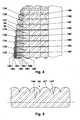
- These surface elements (67, 87)are, for example, lateral surface sections of outwardly curved cylinders, cf. Figures 1 and 5. They are parallel to each other, with the imaginary cylinder axes are oriented transversely to the longitudinal direction of the light guide (10) and their length corresponds to the width of the respective boundary surface (66, 86).
- the surface elements (67, 87)may also be lateral surface sections of ellipsoids, paraboloids, etc. These can be convex or concave.
- the imaginary axes of these surface elementsmay also be oblique to the longitudinal direction of the light guide (10).
- the light exit surfaces (71, 91)are sections of cylinder jacket surfaces.
- the associated cylinderswhich are parallel to the horizontal center longitudinal plane, for example, have the length of the light guide body (10) and an oval cross-section. They are each offset by one quarter of the height of the light guide (10) to the horizontal center longitudinal plane.
- the height of the light exit surfaces (71, 91)corresponds for example to approximately one third of the height of the light guide body (10).
- optical lensesmay be arranged on the light exit surfaces (71, 91).
- the light guide body (10)has an upper (62) and a lower mounting flange (82).
- These attachment flanges (62, 82)are, for example, parts of the upper (61) and lower Lichtauskoppelmaschine (81).
- the light guide body (10)is produced, for example, by injection molding. In this case, for example, at least the electrical part of a light-emitting diode (6) can be formed.
- the light guide body (10)is largely homogeneous by this manufacturing process. Individual areas of the surface of the light guide (10) can be mirrored.
- the lighting unit (2)For installation in a motor vehicle, the lighting unit (2) is fastened, for example, to the upper (62) and the lower mounting flange (82) in the vehicle body and the light source (6) is electrically connected. Optionally, located between the light exit surfaces (71, 91) is not shown here aperture.
- the installation dimensions of the lighting unit (2) in the motor vehicleare essentially determined by the dimensions of the light guide body (10).
- the installation length of the lighting unit (2)corresponds to the length of the light guide (10) and the installation height of the height of the light guide (10).
- the installation depth, cf. FIG. 2is determined by the depth of the optical waveguide (10) and the light source (6).
- the light exit surfaces (71, 91)are visible from outside the motor vehicle. These appear as uniform, color-coordinated surfaces.
- the light (101-109) emitted by the light source (6)passes in the direction of irradiation (9) through the light entry surface (23) into the light distributor (21) of the light guide body (10).
- the light (101-109)strikes the boundary surfaces of the recess (25) formed by the boundary surfaces (26, 27).
- these interfacesare light redirecting and refracting surfaces (126, 127).
- the light (102-109) incident on the light-deflecting and refracting surfaces (126, 127) at an angle greater than the material-specific critical angleis reflected at these surfaces (126, 127).
- the two symmetrically arranged Lichtumlenkungs- and refraction surfaces (126, 127)form a light divider (125).
- the light (102-109)is deflected both into the half of the light distributor (21) shown in FIG. 2 above and into the half of the light distributor (21) shown in the same figure below.
- the reflected, diverging light (102-109)is shown simplified as a parallel light bundle (102-109).
- the two light reflectors (126, 127) of the light divider (125)are for each half of the light distributor (21) indirect light sources.
- the reflected light (102-109)is directed in the direction of the step surfaces (32, 42), cf. FIG. 4.
- FIG. 4shows a detail of the light deflection region shown in the upper half of FIG.
- This respective sectionis a light deflection surface (132-139).
- These light deflection surfaces (132-139)are staggered, Of the illustrated Lichtumlenk vom (132-139), the Lichtumlenk materials (132) has the smallest distance to the light reflector (126) and the Lichtumlenk Chemistry (139) farthest from the light reflector (126) is removed.
- the light source (6)is switched on, the part (102) of the light (102-109) illuminates the light deflection surface (132), the light part (103) illuminates the light deflection surface (133), etc.
- the individual regions of the light (102-109 )are when leaving the light reflector (126) immediately next to each other.
- the interfaces formed by the back surfaces (33, 43)are open spaces.
- the light (105) illuminating, for example, the light deflection surface (135)is reflected to the right on this light deflection surface (135) in the illustration of FIG.
- the resultis a light band (105) which is wider than the adjacent light band (104).
- the light intensity, which is reflected at the Lichtumlenk preparation (135)greater than the light intensity, which is deflected at the Lichtumlenk materials (134).
- this light band (105)is narrower than that Light band (106) which is reflected at the Lichtumlenk materials (136).
- a lower light intensityis deflected at the light deflection surface (135) than at the light deflection surface (136).
- the partial luminous fluxes of the deflected light bundleare thus at least approximately the same.
- the light (107)which, when leaving the light reflector (126) in the representation of FIGS. 2 and 4, is located to the right of the light part (106), touches the light deflection surface (136) in its apex line (34) and illuminates the light deflection surface which is farthest further away (137).
- the light part (106)in turn, which illuminates the light deflection surface (136), tangents the light deflection surface (135).
- the entire reflected light (102-109)strikes the light deflection surfaces (132-139).
- the light (102-109) incident on the light diverting surfaces (132-139)has i.a. due to the absorption of the material a different light intensity.
- the more distant light deflection surfaces (132-139)are illuminated with a lower light intensity or illuminance than the closer light deflection surfaces (132-139).
- the imaginary center lines of the individual light deflection surfaces (132-139)have at least approximately the same distance from one another and, in this exemplary embodiment, are parallel to one another.
- the staggering of the Lichtumlenk vom (132-139), the distance between the individual vertex sections (34, 35, 34, 36) to each otherdecreases with increasing distance of the Lichtumlenk materials (132 - 139) from the light reflector (126).
- the Lichtumsch vom (132-139)can also be composed of several individual surfaces.
- the light bundle (102-109) reflected at the light deflection surfaces (132-139)is largely homogeneous, since the lower light intensity in the sections remote from the light reflector (126, 127) is compensated by a larger light deflection surface (132-139).
- the homogeneously distributed light (101-109)strikes the boundary surfaces of the light-conducting body (10) formed by the notched surfaces (52, 53).
- the two interfacesinclude the complementary angle of the V-shaped notch (51) at 360 degrees, e.g. at least an angle of 260 degrees. They form a deflection light divider (151) whose imaginary plane of symmetry is aligned normal to the imaginary plane of symmetry of the light divider (125).
- the deflection light distributor (151)has two reflection surfaces (152, 153), at which the incident light (101 - 109) in the illustration of Figures 1 and 3 is deflected upwards or downwards. By means of the curvature of the reflection surfaces (152, 153), the light (101-109) reflected on them can be bundled.
- these surfaces (152, 153)may have scattering optics which, for example, scatter the light (101-109) in the longitudinal direction of the light guide body (10).
- the light (101-109) reflected at the deflection light divider (151)strikes the boundary surfaces of the light guide body (10) formed by the boundary surfaces (66, 86) of the longitudinal notches (63, 83).
- the surface elements (67, 87)form segmented total reflection optics (166), which redirect the incident light (101 - 109) in the direction of the light exit surfaces (71, 91).
- the light (101-109)is fanned out, for example, by means of the semicylindrical reflection elements (167) shown in FIG. 5 in the longitudinal direction of the light guide body (10).
- the reflection elements (167)can For example, be sections of cylinder segments whose segment angle is less than 180 degrees.
- the base of the cylindersmay also be limited by a parabola section, an elliptical section, etc.
- the optical axis of the reflection elements (167) shown heremay also include an angle with the longitudinal axis of the light guide body (10) which is not equal to 90 degrees.
- the thus reflected and expanded light beam (102 - 109)passes through the light exit surfaces (71, 91) in the environment (1).
- the imaginary axes of the light exit surfaces (71, 91)are, for example, parallel to the imaginary plane of symmetry of the deflecting light divider (151).
- the light exit surfaces (71, 91)appear as homogeneously illuminated surfaces.
- the light exit surfaces (71, 91)can therefore be designed freely in the manufacture of the lighting unit (2) and, e.g. be adapted to the body of the motor vehicle and, for example, follow its outer contour.
- the light exit surfaces (71, 91) surfacesappear e.g. optically smooth.
- the lighting unit (2)can be constructed asymmetrically.
- the light deflection surfaces (132-139)can, for example, be illuminated directly by the light source (6).
- the lighting unit (2)may also have a plurality of light sources (6) and / or a plurality of light guide bodies (10).
- the reflection surfaces (152, 153) of the deflection light distributor (151) and / or the light deflection surfaces (130-140)can have scattering optics (166).
- the lighting unit (2)In the motor vehicle, only a small installation space is required for the lighting unit (2).
- the lighting unit (2)By arranging the light source (6) on the back (11), the lighting unit (2) can be installed laterally flush.
- a plurality of lighting units (2)can be arranged side by side and so e.g. two parallel uninterrupted long, homogeneously luminous light bands are generated.
- the arrangement of several lighting units (2) one above the otheris conceivable.
- the direction of irradiation (9)is normal to an imaginary tangential plane of the two light exit surfaces (71, 91).
- the light source (6)can also be arranged so that the direction of incidence (9) with the tangential plane encloses an acute solid angle.
- the lighting unit (2)can be made in one or more parts.
Landscapes
- Engineering & Computer Science (AREA)
- Physics & Mathematics (AREA)
- General Engineering & Computer Science (AREA)
- Optics & Photonics (AREA)
- General Physics & Mathematics (AREA)
- Microelectronics & Electronic Packaging (AREA)
- Non-Portable Lighting Devices Or Systems Thereof (AREA)
- Planar Illumination Modules (AREA)
Abstract
Description
Translated fromGermanDie Erfindung betrifft eine Leuchteinheit mit mindestens einer Lichtquelle und mindestens einem der Lichtquelle optisch nachgeschalteten Lichtleitkörper mit direkt oder indirekt von der Lichtquelle ausgeleuchteten, gestaffelt angeordneten Lichtumlenkflächen.The invention relates to a lighting unit with at least one light source and at least one light guide body optically connected downstream of the light source, with light deflection surfaces illuminated directly or indirectly by the light source.
Aus der EP 1 167 869 A2 ist eine derartige Leuchteinheit bekannt. Der Lichtleitkörper ist ein keilförmiges Bauteil, dessen Spitze von der Lichtquelle abgewandt ist. Die beiden Keilflächen, von denen die eine Reflexionsfläche und die andere eine Lichtaustrittsfläche ist, haben eine regelmäßige Struktur. Die Lichtaustrittsfläche hat eine Zusatzoptik, um einen gewünschten optischen Eindruck zu erzielen. Die Gestalt der Lichtaustrittsfläche ist somit vom gewünschten optischen Effekt abhängig.From EP 1 167 869 A2 such a lighting unit is known. The light guide body is a wedge-shaped component, the tip of which is remote from the light source. The two wedge surfaces, one of which is a reflection surface and the other a light exit surface, have a regular structure. The light exit surface has an additional optics to achieve a desired visual impression. The shape of the light exit surface is thus dependent on the desired optical effect.
Der vorliegenden Erfindung liegt daher die Problemstellung zugrunde, eine Leuchteinheit zur Erzeugung homogen verteilten ausgekoppelten Lichts zu entwickeln, deren Lichtaustrittsfläche weitegehend frei gestaltet werden kann.The present invention is therefore based on the problem to develop a lighting unit for generating homogeneously distributed decoupled light, the light exit surface can be made largely free.
Diese Problemstellung wird mit den Merkmalen des Hauptanspruches gelöst. Dazu ist der Flächeninhalt einer Lichtumlenkfläche umso größer, je größer der Abstand dieser Lichtumlenkfläche von der die Lichtumlenkflächen ausleuchtenden Lichtquelle oder von einem die Lichtumlenkflächen ausleuchtenden Lichtreflektor ist.This problem is solved with the features of the main claim. For this purpose, the surface area of a light deflection surface is greater, the greater the distance of this light deflection surface from the illuminating the Lichtumlenkflächen light source or from a Lichtumlenkflächen illuminating light reflector is.
Weitere Einzelheiten der Erfindung ergeben sich aus den Unteransprüchen und der nachfolgenden Beschreibung einer schematisch dargestellten Ausführungsform.
- Figur 1:
- Dimetrische Ansicht eines Lichtleitkörpers;
- Figur 2:
- Leuchteinheit mit einem Lichtleitkörpers nach Figur 1;
- Figur 3:
- Seitenansicht des Lichtleitkörpers nach Figur 1;
- Figur 4:
- Detail eines Lichtumlenkbereichs;
- Figur 5:
- Detail eines Umlenk-Reflektors mit einer Streuoptik.
- FIG. 1:
- Dimetric view of an optical fiber body;
- FIG. 2:
- Lighting unit with a light guide according to Figure 1;
- FIG. 3:
- Side view of the light guide according to Figure 1;
- FIG. 4:
- Detail of a light deflection area;
- FIG. 5:
- Detail of a deflecting reflector with a scattering optics.
Die Figur 2 zeigt die Draufsicht auf eine Leuchteinheit (2), beispielsweise eine Heckleuchte eines Kraftfahrzeuges. Die Leuchteinheit (2) umfasst eine Lichtquelle (6), z.B. eine Leuchtdiode, eine Glühlampe, Halogenlampe, etc., und einen der Lichtquelle (6) optisch nachgeschalteten Lichtleitkörper (10). Die Lichtquelle (6) kann an den Lichtleitkörper (10) angesetzt sein, in diesen eingeformt sein, eingeclipst sein, etc.FIG. 2 shows the plan view of a lighting unit (2), for example a tail lamp of a motor vehicle. The lighting unit (2) comprises a light source (6), e.g. a light emitting diode, an incandescent lamp, a halogen lamp, etc., and a light guide body (10) optically connected downstream of the light source (6). The light source (6) can be attached to the light guide body (10), be molded into it, be clipped, etc.
Die Figuren 1 und 3 zeigen den Lichtleitkörper (10) ohne die Lichtquelle (6). Hierbei zeigt die Figur 1 eine dimetrische Ansicht von der Rückseite (11) und die Figur 3 eine Seitenansicht des Lichtleitkörpers (10).Figures 1 and 3 show the light guide body (10) without the light source (6). FIG. 1 shows a dimetric view of the rear side (11) and FIG. 3 shows a side view of the light guide body (10).
Bei einer in einem hier nicht dargestellten Kraftfahrzeug eingebauten Leuchteinheit (2) sitzt die Lichtquelle (6) beispielsweise innerhalb des Kraftfahrzeuges an der Rückseite (11) des Lichtleitkörpers (10). Von außerhalb des Kraftfahrzeugs sind von der Leuchteinheit (2) z.B. zwei Lichtaustrittsflächen (71, 91) sichtbar, die die Fahrzeugkontur begrenzen. Diese Lichtaustrittsflächen (71, 91) sind beispielsweise auf der Vorderseite (12) des Lichtleitkörpers (10) angeordnet.In a lighting unit (2) installed in a motor vehicle, not shown here, the light source (6) is seated, for example, inside the motor vehicle on the rear side (11) of the light guide body (10). From outside the motor vehicle, the lighting unit (2) has e.g. two light exit surfaces (71, 91) visible, which limit the vehicle contour. These light exit surfaces (71, 91) are arranged, for example, on the front side (12) of the light guide body (10).
Die Leuchteinheit (2) ist z.B. achsensymmetrisch sowohl in Bezug auf eine gedachte horizontale Mittenlängsebene als auch bezüglich einer gedachten vertikalen Mittenquerebene durch die Lichtquelle (6). Diese beiden genannten Ebenen schneiden sich in einer gedachten, in der Einstrahlrichtung (9) orientierten Geraden durch die Lichtquelle (6).The lighting unit (2) is e.g. axisymmetric both with respect to an imaginary horizontal center longitudinal plane and with respect to an imaginary vertical center transverse plane through the light source (6). These two mentioned planes intersect in an imaginary straight line oriented in the direction of irradiation (9) through the light source (6).
Der Lichtleitkörper (10) ist beispielsweise ein einstückiger transparenter Kunststoffkörper, z.B. aus PMMA, modifiziertes PMMI, etc. Er besteht beispielsweise aus einem Lichtverteiler (21), einer oberen Lichtauskoppeleinheit (61) und einer unteren Lichtauskoppeleinheit (81). Seine Länge beträgt in dem in den Figuren 1 - 3 dargestellten Ausführungsbeispiel das Vierfache seiner Tiefe und das 2,4-fache seiner Höhe.The light guide body (10) is for example a one-piece transparent plastic body, e.g. PMMA, modified PMMI, etc. It consists, for example, of a light distributor (21), an upper light output unit (61) and a lower light output unit (81). Its length is in the embodiment illustrated in Figures 1-3 - four times its depth and 2.4 times its height.
Der Lichtverteiler (21) ist hier ein sichelförmiges Bauteil. Er ist im Ausführungsbeispiel genauso lang wie der Lichtleitkörper (10). Seine Tiefe beträgt etwa 11% seiner Länge, seine Höhe ungefähr 6% der Länge. Symmetrisch zur vertikalen Mittenquerebene liegt in der rückseitigen Außenfläche (22) eine Lichteintrittsfläche (23). Diese ist beispielsweise eine quadratische Planfläche, deren Kantenlänge der Höhe des Lichtverteilers (21) entspricht.The light distributor (21) is here a crescent-shaped component. He is in the embodiment as long as the light guide (10). Its depth is about 11% of its length, its height about 6% of its length. Symmetrically to the vertical center transverse plane lies in the rear outer surface (22) has a light entrance surface (23). This is, for example, a square planar surface whose edge length corresponds to the height of the light distributor (21).
Auf beiden Seiten der Lichteintrittsfläche (23) besteht die Außenfläche (22) aus jeweils einem gestuften Bereich (31; 41), der die Lichteintrittsfläche (23) mit der jeweiligen Stirnseite (13, 14) verbindet.On both sides of the light entry surface (23), the outer surface (22) consists in each case of a stepped region (31; 41) which connects the light entry surface (23) with the respective end face (13, 14).
Die einzelnen Stufen (32, 33; 42, 43) des jeweiligen gestuften Bereiches (31; 41) bestehen aus Stufenflächen (32; 42) und an diese angrenzende Rückseitenflächen (33; 43). Sie sind Grenzflächen des Lichtverteilers (21) zur Umgebung (1). Die einzelnen Stufenflächen (32; 42) liegen z.B. annähernd parallel zueinander und stehen normal zur horizontalen Mittenlängsebene der Leuchteinheit. Mit der vertikalen Mittenquerebene schließen sie beispielsweise einen Winkel von 45 Grad ein. Die Stufenflächen (32; 42) können mit diesen Ebenen auch unterschiedliche Winkel einschließen.The individual steps (32, 33, 42, 43) of the respective stepped area (31, 41) consist of step surfaces (32, 42) and adjoining rear side surfaces (33, 43). They are interfaces of the light distributor (21) to the environment (1). The individual step surfaces (32; approximately parallel to each other and are normal to the horizontal center longitudinal plane of the lighting unit. For example, with the vertical center transverse plane, they include an angle of 45 degrees. The step surfaces (32; 42) may also include different angles with these planes.
Eine Stufenfläche (32; 42) und eine der beiden an diese angrenzenden Rückseitenflächen (33; 43) schließen in der Darstellung der Figur 2 miteinender einen Winkel von 90 Grad ein. Dieser eingeschlossene Winkel kann auch ein spitzer oder ein stumpfer Winkel sein. Die Scheitelstrecke (34; 44), die in der Draufsicht der Figur 2 als Scheitelpunkt dargestellt ist, ist die Spitzenlinie einer konkaven Kerbe.A step surface (32; 42) and one of the two adjoining back face surfaces (33; 43) in the illustration of Figure 2 enclose an angle of 90 degrees with each other. This included angle can also be a sharp or an obtuse angle. The crest (34; 44), which is shown as a vertex in the plan view of Figure 2, is the top line of a concave notch.
Innerhalb der jeweiligen gestuften Bereiche (31; 41) ist der Abstand der einzelnen Scheitelstrecken (34; 44) zueinander nicht konstant. Der Abstand einer beliebigen Scheitelstrecke (34; 44) zu einer Scheitelstrecke (35; 45), die weiter entfernt ist von der Lichteintrittsfläche (23), ist kleiner als der Abstand zu einer Scheitelstrecke (36; 46), die näher an der Lichteintrittsfläche (23) liegt. Der Abstand zweier benachbarter Scheitelstrecken (34, 35; 34, 36; 44, 45; 44, 46) ist umso kleiner, je weiter diese Scheitelstrecken (34, 35; 34, 36; 44, 45; 44, 46) von der Lichteintrittsfläche (23) entfernt liegen.Within the respective stepped regions (31; 41), the distance between the individual vertex paths (34; 44) is not constant relative to one another. The distance of an arbitrary crest (34; 44) to a crest (35; 45) which is farther away from the light entry surface (23) is smaller than the distance to a crest (36; 46) which is closer to the light entry surface (36; 23). The distance between two adjacent vertex paths (34, 35, 34, 36, 44, 45, 44, 46) is the smaller, the farther these vertex paths (34, 35; 34, 36; 44, 45; 44, 46) are located away from the light entry surface (23).
Der Lichtverteiler (21) hat eine Aussparung (25) mit z.B. viereckigem Querschnitt, die symmetrisch zur vertikalen Mittenquerebene liegt. Die Länge der kurzen Diagonalen der Aussparung (25) beträgt z.B. 44%, die Länge der langen Diagonalen beispielsweise 80% der Tiefe des Lichtverteilers (21). Der Abstand dieser Aussparung (25) von der Lichteintrittsfläche (23) beträgt beispielsweise ein Fünftel der Tiefe des Lichtverteilers (21). Der Querschnitt der Aussparung (25) kann sich z.B. in Richtung der horizontalen Mittenlängsebene verjüngen.The light distributor (21) has a recess (25) with e.g. quadrangular cross-section symmetrical to the vertical center transverse plane. The length of the short diagonal of the recess (25) is e.g. 44%, the length of the long diagonal, for example, 80% of the depth of the light distributor (21). The distance of this recess (25) from the light entry surface (23) is for example one fifth of the depth of the light distributor (21). The cross-section of the recess (25) may be e.g. taper in the direction of the horizontal center longitudinal plane.
Die näher an der Lichteintrittsfläche (23) liegenden Begrenzungsflächen (26, 27) der Aussparung (25) sind beispielsweise Abschnitte von Mantelflächen eines Zylinders, eines Ellipsoids, eines Paraboloids, eines Kegels, etc. Sind die Begrenzungsflächen (26, 27) Abschnitte von Zylinder- oder Kegelmantelflächen, kann die Grundfläche des Zylinders oder des Kegels kreisförmig, ellipsenförmig, oval etc. sein. Die Grundfläche kann auch durch eine beliebig gekrümmte, stetige oder unstetige Raumkurve begrenzt sein, z.B. durch eine Parabel. Es ist auch denkbar, diese Begrenzungsflächen (26, 27) als Planflächen auszuführen.The boundary surfaces (26, 27) of the recess (25) closer to the light entry surface (23) are, for example, sections of lateral surfaces of a cylinder, an ellipsoid, a paraboloid, a cone, etc. If the boundary surfaces (26, 27) are sections of cylinder - Or conical surfaces, the base of the cylinder or the cone may be circular, elliptical, oval, etc. The base may also be bounded by an arbitrarily curved, continuous or discontinuous space curve, e.g. through a parabola. It is also conceivable to execute these boundary surfaces (26, 27) as plane surfaces.
Auch die Begrenzungsflächen (28, 29) der Aussparung (25), die von der Lichteintrittsfläche (23) weiter entfernt sind, können Planflächen, Abschnitte von Mantelflächen eines Zylinders, eines Ellipsoids, eines Paraboloids, eines Kegels, etc. sein.The boundary surfaces (28, 29) of the recess (25), which are further away from the light entry surface (23) may be planar surfaces, portions of lateral surfaces of a cylinder, an ellipsoid, a paraboloid, a cone, etc.
Auf der Vorderseite (12) hat der Lichtverteiler (21) eine in der Längsrichtung des Lichtleitkörpers (10) orientierte, zumindest annähernd v-förmige Kerbe (51), deren Mittelebene mit der horizontalen Mittenlängsebene der Leuchteinheit (2) zusammenfällt. Die Kerbflächen (52, 53) sind beispielsweise Oberflächenabschnitte eines Zylindermantels, wobei der Zylinder eine Grundfläche hat, die kreisförmig, elliptisch, oval, etc. ist oder die durch eine geschlossene, stetig oder unstetig gekrümmte Raumkurve begrenzt ist. Gegebenenfalls können die Kerbflächen (52, 53) auch ebene Flächen sein oder aus einzelnen stetigen oder unstetig gekrümmten Flächenelementen zusammengesetzt sein. Der von den beiden Kerbflächen (52, 53) eingeschlossene Kerbwinkel ist beispielsweise kleiner als 100 Grad.On the front side (12), the light distributor (21) has an at least approximately V-shaped notch (51) oriented in the longitudinal direction of the light guide body (10) whose center plane coincides with the horizontal center longitudinal plane of the lighting unit (2). The notched surfaces (52, 53) are, for example, surface sections of a cylinder jacket, the cylinder having a base area which is circular, elliptical, oval, etc. or which is delimited by a closed, continuously or discontinuously curved space curve. Optionally, the notched surfaces (52, 53) may also be flat surfaces or composed of individual continuous or discontinuous curved surface elements. For example, the notch angle included by the two notched
Die beiden Lichtauskoppeleinheiten (61, 81) sind symmetrisch zur horizontalen Mittenlängsebene der Leuchteinheit (2) angeordnet. Ihre Länge entspricht im Ausführungsbeispiel der Länge des Lichtleitkörpers (10), ihre Tiefe beträgt etwa zwei Drittel der Tiefe des Lichtleitkörpers (10).The two light output units (61, 81) are arranged symmetrically to the horizontal center longitudinal plane of the lighting unit (2). Their length corresponds in the embodiment of the length of the light guide (10), its depth is about two-thirds of the depth of the light guide (10).
Auf der Rückseite (11) hat jede Lichtauskoppeleinheit (61, 81) auf ihrer gesamten Länge eine dreieckige Längskerbe (63, 83), deren Tiefe annähernd 20% der Tiefe des Lichtleitkörpers (10) beträgt. Die Scheitellinien (64, 84) der Längskerben (63, 83) liegen hier um ein Drittel der Höhe des Lichtleitkörpers (10) versetzt zur horizontalen Mittenlängsebene. Der Kerbwinkel der Längskerben (63, 83) beträgt beispielsweise 46 Grad. Die von der horizontalen Mittenlängsebene entfernten Begrenzungsflächen (65, 85) der Längskerben (63, 83) sind z.B. ebene Flächen, die parallel zur horizontalen Mittenlängsebene liegen.On the rear side (11) each light extraction unit (61, 81) has over its entire length a triangular longitudinal notch (63, 83) whose depth is approximately 20% of the depth of the light guide body (10). The apex lines (64, 84) of the longitudinal notches (63, 83) are here offset by one third of the height of the light guide body (10) offset from the horizontal center longitudinal plane. The notch angle of the longitudinal notches (63, 83) is for example 46 degrees. The boundary surfaces (65, 85) of the longitudinal notches (63, 83) remote from the horizontal center longitudinal plane are e.g. flat surfaces that are parallel to the horizontal center longitudinal plane.
Die näher an der horizontalen Mittenlängsebene liegenden Begrenzungsflächen (66, 86) der Längskerben (63, 83) sind aus einzelnen Flächenelementen (67, 87) zusammengesetzt. Diese Flächenelemente (67, 87) sind beispielsweise Mantelflächenabschnitte nach außen gewölbter Zylinder, vgl. die Figuren 1 und 5. Sie liegen parallel zueinander, wobei die gedachten Zylinderachsen quer zur Längsrichtung des Lichtleitkörpers (10) orientiert sind und ihre Länge der Breite der jeweiligen Begrenzungsfläche (66, 86) entspricht. Die Flächenelemente (67, 87) können auch Mantelflächenabschnitte von Ellipsoiden, Paraboloiden etc. sein. Diese können konvex oder konkav gewölbt sein. Die gedachten Achsen dieser Flächenelemente können auch schräg zur Längsrichtung des Lichtleitkörpers (10) liegen.The closer to the horizontal center longitudinal plane lying boundary surfaces (66, 86) of the longitudinal notches (63, 83) are composed of individual surface elements (67, 87). These surface elements (67, 87) are, for example, lateral surface sections of outwardly curved cylinders, cf. Figures 1 and 5. They are parallel to each other, with the imaginary cylinder axes are oriented transversely to the longitudinal direction of the light guide (10) and their length corresponds to the width of the respective boundary surface (66, 86). The surface elements (67, 87) may also be lateral surface sections of ellipsoids, paraboloids, etc. These can be convex or concave. The imaginary axes of these surface elements may also be oblique to the longitudinal direction of the light guide (10).
Die Lichtaustrittsflächen (71, 91) sind Abschnitte von Zylindermantelflächen. Die zugehörigen Zylinder, die parallel zur horizontalen Mittenlängsebene liegen, haben beispielsweise die Länge des Lichtleitkörpers (10) und einen ovalen Querschnitt. Sie sind jeweils um ein Viertel der Höhe des Lichtleitkörpers (10) zur horizontalen Mittenlängsebene versetzt. Die Höhe der Lichtaustrittsflächen (71, 91) entspricht beispielsweise annähernd einem Drittel der Höhe des Lichtleitkörpers (10).The light exit surfaces (71, 91) are sections of cylinder jacket surfaces. The associated cylinders, which are parallel to the horizontal center longitudinal plane, for example, have the length of the light guide body (10) and an oval cross-section. They are each offset by one quarter of the height of the light guide (10) to the horizontal center longitudinal plane. The height of the light exit surfaces (71, 91) corresponds for example to approximately one third of the height of the light guide body (10).
Auf den Lichtaustrittsflächen (71, 91) können optische Linsen angeordnet sein.On the light exit surfaces (71, 91) optical lenses may be arranged.
Zur Befestigung z.B. im Kraftfahrzeug, hat der Lichtleitkörper (10) einen oberen (62) und einen unteren Befestigungsflansch (82). Diese Befestigungsflansche (62, 82) sind beispielsweise Teile der oberen (61) bzw. der unteren Lichtauskoppeleinheit (81).For attachment e.g. In the motor vehicle, the light guide body (10) has an upper (62) and a lower mounting flange (82). These attachment flanges (62, 82) are, for example, parts of the upper (61) and lower Lichtauskoppeleinheit (81).
Bei der Herstellung der Leuchteinheit (2) wird der Lichtleitkörper (10) beispielsweise im Spritzgießverfahren erzeugt. Hierbei kann beispielsweise zumindest der elektrische Teil einer Leuchtdiode (6) eingeformt werden. Der Lichtleitkörper (10) wird durch dieses Herstellungsverfahren weitgehend homogenen. Einzelne Bereiche der Oberfläche des Lichtleitkörpers (10) können verspiegelt werden.In the production of the lighting unit (2), the light guide body (10) is produced, for example, by injection molding. In this case, for example, at least the electrical part of a light-emitting diode (6) can be formed. The light guide body (10) is largely homogeneous by this manufacturing process. Individual areas of the surface of the light guide (10) can be mirrored.
Zum Einbau in ein Kraftfahrzeug wird die Leuchteinheit (2) beispielsweise mit dem oberen (62) und dem unteren Befestigungsflansch (82) in der Fahrzeugkarosserie befestigt und die Lichtquelle (6) elektrisch angeschlossen. Gegebenenfalls liegt zwischen den Lichtaustrittsflächen (71, 91) eine hier nicht dargestellte Blende. Die Einbaumaße der Leuchteinheit (2) im Kraftfahrzeug werden im Wesentlichen durch die Abmessungen des Lichtleitkörpers (10) bestimmt. So entspricht die Einbaulänge der Leuchteinheit (2) der Länge des Lichtleitkörpers (10) und die Einbauhöhe der Höhe des Lichtleitkörpers (10). Die Einbautiefe, vgl. Figur 2, wird durch die Tiefe des Lichtleitkörpers (10) und die Lichtquelle (6) bestimmt.For installation in a motor vehicle, the lighting unit (2) is fastened, for example, to the upper (62) and the lower mounting flange (82) in the vehicle body and the light source (6) is electrically connected. Optionally, located between the light exit surfaces (71, 91) is not shown here aperture. The installation dimensions of the lighting unit (2) in the motor vehicle are essentially determined by the dimensions of the light guide body (10). Thus, the installation length of the lighting unit (2) corresponds to the length of the light guide (10) and the installation height of the height of the light guide (10). The installation depth, cf. FIG. 2, is determined by the depth of the optical waveguide (10) and the light source (6).
Bei einer ausgeschalteten Leuchteinheit (2) sind von außerhalb des Kraftfahrzeuges die Lichtaustrittsflächen (71, 91) sichtbar. Diese erscheinen als gleichmäßige, farblich homogene Flächen.When the lighting unit (2) is switched off, the light exit surfaces (71, 91) are visible from outside the motor vehicle. These appear as uniform, color-coordinated surfaces.
Beim Betrieb der Leuchteinheit (2) tritt das von der Lichtquelle (6) emittierte Licht (101 - 109) in Einstrahlrichtung (9) durch die Lichteintrittsfläche (23) hindurch in den Lichtverteiler (21) des Lichtleitkörpers (10). Im Lichtverteiler (21) trifft das Licht (101 - 109) auf die Grenzflächen der Aussparung (25), die durch die Begrenzungsflächen (26, 27) gebildet werden. Für das auftreffende Licht (101 - 109) sind diese Grenzflächen Lichtumlenkungs- und Brechungsflächen (126, 127).During operation of the lighting unit (2), the light (101-109) emitted by the light source (6) passes in the direction of irradiation (9) through the light entry surface (23) into the light distributor (21) of the light guide body (10). In the light distributor (21), the light (101-109) strikes the boundary surfaces of the recess (25) formed by the boundary surfaces (26, 27). For the incident light (101-109), these interfaces are light redirecting and refracting surfaces (126, 127).
Licht (101), das auf diese Flächen (126, 127) unter einem Winkel zur Normalen auftrifft, der kleiner ist als der Grenzwinkel der Totalreflexion - bei einem Lichtleitkörper aus PMMA ist dieser Winkel beispielsweise 43 Grad - tritt unter Brechung durch die Lichtumlenk- und Brechungsfläche (126, 129) hindurch in die Aussparung (25). Durch die Begrenzungsflächen (28, 29) tritt ein Teil dieses Lichts (101) - unter erneuter Brechung - wieder in den Lichtleitkörper (10) ein.Light (101) incident on said surfaces (126, 127) at an angle to the normal smaller than the critical angle the total reflection - this angle is, for example, 43 degrees in the case of a light guide body of PMMA - passes into the recess (25) while being refracted by the light deflection and refraction surface (126, 129). Through the boundary surfaces (28, 29) enters a part of this light (101) - with renewed refraction - again in the light guide body (10).
Das Licht (102 - 109), das unter einem Winkel auf die Lichtumlenk- und Brechungsflächen (126, 127) auftrifft, der größer ist als der werkstoffspezifische Grenzwinkel, wird an diesen Flächen (126, 127) reflektiert.The light (102-109) incident on the light-deflecting and refracting surfaces (126, 127) at an angle greater than the material-specific critical angle is reflected at these surfaces (126, 127).
Die beiden symmetrisch zueinander angeordneten Lichtumlenkungs- und Brechungsflächen (126, 127) bilden einen Lichtteiler (125). Beim Auftreffen auf den Lichtteiler (125) wird das Licht (102 - 109) sowohl in die in der Figur 2 oben dargestellte Hälfte des Lichtverteilers (21), als auch in die in derselben Figur unten dargestellte Hälfte des Lichtverteilers (21) abgelenkt. In den Figuren 2 und 4 ist das reflektierte, divergierende Licht (102 - 109) vereinfacht als paralleles Lichtbündel (102 - 109) dargestellt.The two symmetrically arranged Lichtumlenkungs- and refraction surfaces (126, 127) form a light divider (125). Upon impact with the light divider (125), the light (102-109) is deflected both into the half of the light distributor (21) shown in FIG. 2 above and into the half of the light distributor (21) shown in the same figure below. In FIGS. 2 and 4, the reflected, diverging light (102-109) is shown simplified as a parallel light bundle (102-109).
Die beiden Lichtreflektoren (126, 127) des Lichtteilers (125) sind für jeweils eine Hälfte des Lichtverteilers (21) indirekte Lichtquellen. Im Lichtverteiler (21) wird das reflektierte Licht (102 - 109) in Richtung der Stufenflächen (32, 42) geleitet, vgl. Figur 4.The two light reflectors (126, 127) of the light divider (125) are for each half of the light distributor (21) indirect light sources. In the light distributor (21), the reflected light (102-109) is directed in the direction of the step surfaces (32, 42), cf. FIG. 4.
Die Figur 4 zeigt ein Detail des in der oberen Hälfte der Figur 2 dargestellten Lichtumlenkbereiches. An den jeweiligen Grenzflächen (32, 42) wird jeweils nur ein an die Scheitelstrecke (34; 44) angrenzender Abschnitt ausgeleuchtet. Dieser jeweilige Abschnitt ist eine Lichtumlenkfläche (132 - 139). Diese Lichtumlenkflächen (132 - 139) sind gestaffelt angeordnet, wobei von den dargestellten Lichtumlenkflächen (132 - 139) die Lichtumlenkfläche (132) den geringsten Abstand zum Lichtreflektor (126) hat und die Lichtumlenkfläche (139) am weitesten vom Lichtreflektor (126) entfernt ist. Bei eingeschalteter Lichtquelle (6) leuchtet der Teil (102) des Lichtes (102 - 109) die Lichtumlenkfläche (132) aus, der Lichtteil (103) beleuchtet die Lichtumlenkfläche (133) beleuchtet, etc. Die einzelnen Bereiche des Lichts (102 - 109) liegen beim Verlassen des Lichtreflektors (126) unmittelbar nebeneinander. Die durch die Rückseitenflächen (33, 43) gebildeten Grenzflächen sind Freiflächen.FIG. 4 shows a detail of the light deflection region shown in the upper half of FIG. At the respective boundary surfaces (32, 42), only one section adjoining the apex path (34, 44) is illuminated in each case. This respective section is a light deflection surface (132-139). These light deflection surfaces (132-139) are staggered, Of the illustrated Lichtumlenkflächen (132-139), the Lichtumlenkfläche (132) has the smallest distance to the light reflector (126) and the Lichtumlenkfläche (139) farthest from the light reflector (126) is removed. When the light source (6) is switched on, the part (102) of the light (102-109) illuminates the light deflection surface (132), the light part (103) illuminates the light deflection surface (133), etc. The individual regions of the light (102-109 ) are when leaving the light reflector (126) immediately next to each other. The interfaces formed by the back surfaces (33, 43) are open spaces.
Je weiter die einzelne Lichtumlenkfläche (132 - 139) vom Lichtreflektor (126) entfernt ist, desto weiter ragt sie in den Lichtverteiler (21) - in der Figur 4 nach rechts - hinein. Hierbei ist der Betrag, um den eine vom Lichtreflektor (126) entfernter liegende Lichtumlenkfläche (133 - 139) weiter in den Lichtverteiler (21) hineinragt als die nächstnähere Lichtumlenkfläche (132 - 138), nicht konstant. Dieser Betrag steigt an mit dem Abstand der Lichtumlenkflächen (132 - 139) zum Lichtreflektor (126). Somit ist - zumindest bei annähernd parallelen Lichtumlenkflächen (132 - 139) - der Flächeninhalt einer weiter entfernt liegenden Lichtumlenkfläche (132 - 139) größer als der Flächeninhalt der nächst näherliegenden Lichtumlenkfläche (132 - 139).The farther the individual light deflection surface (132-139) is away from the light reflector (126), the further it projects into the light distributor (21) - to the right in FIG. 4. In this case, the amount by which a light deflection surface (133-139) located further from the light reflector (126) projects further into the light distributor (21) than the next closest light deflection surface (132-138) is not constant. This amount increases with the distance of the Lichtumlenkflächen (132-139) to the light reflector (126). Thus, at least for approximately parallel light deflection surfaces (132-139), the area of a further light deflection surface 132-139 is greater than the surface area of the nearest light deflection surface 132-139.
Das beispielsweise die Lichtumlenkfläche (135) ausleuchtende Licht (105) wird an dieser Lichtumlenkfläche (135) in der Darstellung der Figur 4 nach rechts reflektiert. Es ergibt sich ein Lichtband (105), das breiter ist als das benachbarte Lichtband (104). Damit ist die Lichtstärke, die an der Lichtumlenkfläche (135) reflektiert wird, größer als die Lichtstärke, die an der Lichtumlenkfläche (134) umgelenkt wird. Gleichzeitig ist dieses Lichtband (105) schmäler als das Lichtband (106) das an der Lichtumlenkfläche (136) reflektiert wird. Hiermit wird an der Lichtumlenkfläche (135) auch eine geringere Lichtstärke umgelenkt als an der Lichtumlenkfläche (136). Die Teillichtströme des umgelenkten Lichtbündels sind damit zumindest annähernd gleich.The light (105) illuminating, for example, the light deflection surface (135) is reflected to the right on this light deflection surface (135) in the illustration of FIG. The result is a light band (105) which is wider than the adjacent light band (104). Thus, the light intensity, which is reflected at the Lichtumlenkfläche (135), greater than the light intensity, which is deflected at the Lichtumlenkfläche (134). At the same time, this light band (105) is narrower than that Light band (106) which is reflected at the Lichtumlenkfläche (136). Hereby, a lower light intensity is deflected at the light deflection surface (135) than at the light deflection surface (136). The partial luminous fluxes of the deflected light bundle are thus at least approximately the same.
Das Licht (107), das beim Verlassen des Lichtreflektors (126) in der Darstellung der Figuren 2 und 4 rechts neben dem Lichtteil (106) liegt, tangiert die Lichtumlenkfläche (136) in ihrer Scheitellinie (34) und leuchtet die nächst weiter entfernte Lichtumlenkfläche (137) aus. Der Lichtteil (106) seinerseits, der die Lichtumlenkfläche (136) ausleuchtet, tangiert die Lichtumlenkfläche (135). Somit trifft das gesamte reflektierte Licht (102 - 109) auf die Lichtumlenkflächen (132 - 139).The light (107) which, when leaving the light reflector (126) in the representation of FIGS. 2 and 4, is located to the right of the light part (106), touches the light deflection surface (136) in its apex line (34) and illuminates the light deflection surface which is farthest further away (137). The light part (106) in turn, which illuminates the light deflection surface (136), tangents the light deflection surface (135). Thus, the entire reflected light (102-109) strikes the light deflection surfaces (132-139).
Das auf die Lichtumlenkflächen (132 - 139) auftreffende Licht (102 - 109) hat u.a. aufgrund der Absorption des Werkstoffs eine unterschiedliche Lichtstärke. So werden die weiter entfernten Lichtumlenkflächen (132 - 139) mit einer geringeren Lichtstärke bzw. Beleuchtungsstärke ausgeleuchtet als die näherliegenden Lichtumlenkflächen (132 - 139).The light (102-109) incident on the light diverting surfaces (132-139) has i.a. due to the absorption of the material a different light intensity. Thus, the more distant light deflection surfaces (132-139) are illuminated with a lower light intensity or illuminance than the closer light deflection surfaces (132-139).
Die gedachten Mittellinien der einzelnen Lichtumlenkflächen (132 - 139) haben zumindest annähernd den gleichen Abstand zueinander und sind in diesem Ausführungsbeispiel zueinander parallel. Die Staffelung der Lichtumlenkflächen (132 - 139), der Abstand der einzelnen Scheitelstrecken (34, 35; 34, 36) zueinander, nimmt ab mit zunehmenden Abstand der Lichtumlenkfläche (132 - 139) vom Lichtreflektor (126).The imaginary center lines of the individual light deflection surfaces (132-139) have at least approximately the same distance from one another and, in this exemplary embodiment, are parallel to one another. The staggering of the Lichtumlenkflächen (132-139), the distance between the individual vertex sections (34, 35, 34, 36) to each other decreases with increasing distance of the Lichtumlenkfläche (132 - 139) from the light reflector (126).
Die Lichtumlenkflächen (132 - 139) können auch aus mehreren Einzelflächen zusammengesetzt sein.The Lichtumlenkflächen (132-139) can also be composed of several individual surfaces.
Das an den Lichtumlenkflächen (132 - 139) reflektierte Lichtbündel (102 - 109) ist weitgehend homogen, da die geringere Lichtstärke in den von dem Lichtreflektor (126, 127) entfernteren Abschnitten durch eine größere Lichtumlenkfläche (132 - 139) ausgeglichen wird.The light bundle (102-109) reflected at the light deflection surfaces (132-139) is largely homogeneous, since the lower light intensity in the sections remote from the light reflector (126, 127) is compensated by a larger light deflection surface (132-139).
Das homogen verteilte Licht (101 - 109) trifft auf die Grenzflächen des Lichtleitkörpers (10), die durch die Kerbflächen (52, 53) gebildet werden. Die beiden Grenzflächen schließen den Komplementärwinkel der V-förmigen Kerbe (51) zu 360 Grad ein, also z.B. mindestens einen Winkel von 260 Grad. Sie bilden einen Umlenk-Lichtteiler (151), dessen gedachte Symmetrieebene normal zur gedachten Symmetrieebene des Lichtteilers (125) ausgerichtet ist. Der Umlenk-Lichtverteiler (151) hat zwei Reflexionsflächen (152, 153), an denen das auftreffende Licht (101 - 109) in der Darstellung der Figuren 1 und 3 nach oben bzw. nach unten umgelenkt wird. Mittels der Wölbung der Reflexionsflächen (152, 153) kann das an ihnen reflektierte Licht (101 - 109) gebündelt werden. Gegebenenfalls können diese Flächen (152, 153) Streuoptiken aufweisen, die beispielsweise das Licht (101 - 109) in Längsrichtung des Lichtleitkörpers (10) streuen.The homogeneously distributed light (101-109) strikes the boundary surfaces of the light-conducting body (10) formed by the notched surfaces (52, 53). The two interfaces include the complementary angle of the V-shaped notch (51) at 360 degrees, e.g. at least an angle of 260 degrees. They form a deflection light divider (151) whose imaginary plane of symmetry is aligned normal to the imaginary plane of symmetry of the light divider (125). The deflection light distributor (151) has two reflection surfaces (152, 153), at which the incident light (101 - 109) in the illustration of Figures 1 and 3 is deflected upwards or downwards. By means of the curvature of the reflection surfaces (152, 153), the light (101-109) reflected on them can be bundled. Optionally, these surfaces (152, 153) may have scattering optics which, for example, scatter the light (101-109) in the longitudinal direction of the light guide body (10).
Das am Umlenk-Lichtteiler (151) reflektierte Licht (101 - 109) trifft auf die Grenzflächen des Lichtleitkörpers (10), die durch die Begrenzungsflächen (66, 86) der Längskerben (63, 83) gebildet werden. Die Flächenelemente (67, 87) bilden segmentierte Totalreflexionsoptiken (166), die das auftreffende Licht (101 - 109) in Richtung der Lichtaustrittsflächen (71, 91) umlenken. Hierbei wird das Licht (101 - 109) beispielsweise mittels der in Figur 5 dargestellten halbzylindrischen Reflexionselemente (167) in Längsrichtung des Lichtleitkörpers (10) aufgefächert. Die Reflexionselemente (167) können beispielsweise auch Abschnitte von Zylindersegmenten sein, deren Segmentwinkel kleiner ist als 180 Grad. Die Grundfläche der Zylinder kann auch durch einen Parabelabschnitt, einen Ellipsenabschnitt, etc. begrenzt sein. Die optische Achse der hier dargestellten Reflexionselemente (167) kann auch mit der Längsachse des Lichtleitkörpers (10) einen Winkel einschließen, der ungleich 90 Grad ist.The light (101-109) reflected at the deflection light divider (151) strikes the boundary surfaces of the light guide body (10) formed by the boundary surfaces (66, 86) of the longitudinal notches (63, 83). The surface elements (67, 87) form segmented total reflection optics (166), which redirect the incident light (101 - 109) in the direction of the light exit surfaces (71, 91). In this case, the light (101-109) is fanned out, for example, by means of the semicylindrical reflection elements (167) shown in FIG. 5 in the longitudinal direction of the light guide body (10). The reflection elements (167) can For example, be sections of cylinder segments whose segment angle is less than 180 degrees. The base of the cylinders may also be limited by a parabola section, an elliptical section, etc. The optical axis of the reflection elements (167) shown here may also include an angle with the longitudinal axis of the light guide body (10) which is not equal to 90 degrees.
Das derart reflektierte und aufgeweitete Lichtbündel (102 - 109) tritt durch die Lichtaustrittsflächen (71, 91) in die Umgebung (1). Die gedachten Achsen der Lichtaustrittsflächen (71; 91) sind beispielsweise parallel zur gedachten Symmetrieebene des Umlenk-Lichtteilers (151).The thus reflected and expanded light beam (102 - 109) passes through the light exit surfaces (71, 91) in the environment (1). The imaginary axes of the light exit surfaces (71, 91) are, for example, parallel to the imaginary plane of symmetry of the deflecting light divider (151).
Beim Betrieb der Leuchteinheit (2) erscheinen die Lichtaustrittsflächen (71, 91) als homogen ausgeleuchtete Flächen. Die Lichtaustrittsflächen (71, 91) können daher bei der Herstellung der Leuchteinheit (2) frei gestaltet werden und z.B. an die Karosserie des Kraftfahrzeugs angepasst werden und beispielsweise dessen Außenkontur folgen. Die Lichtaustrittsflächen (71, 91) Flächen erscheinen z.B. optisch glatt.During operation of the lighting unit (2), the light exit surfaces (71, 91) appear as homogeneously illuminated surfaces. The light exit surfaces (71, 91) can therefore be designed freely in the manufacture of the lighting unit (2) and, e.g. be adapted to the body of the motor vehicle and, for example, follow its outer contour. The light exit surfaces (71, 91) surfaces appear e.g. optically smooth.
Die Leuchteinheit (2) kann unsymmetrisch aufgebaut sein. Die Lichtumlenkflächen (132 - 139) können beispielsweise direkt von der Lichtquelle (6) ausgeleuchtet werden. Auch kann die Leuchteinheit (2) mehrere Lichtquellen (6) und/oder mehrere Lichtleitkörper (10) aufweisen.The lighting unit (2) can be constructed asymmetrically. The light deflection surfaces (132-139) can, for example, be illuminated directly by the light source (6). The lighting unit (2) may also have a plurality of light sources (6) and / or a plurality of light guide bodies (10).
Die Reflexionsflächen (152, 153) des Umlenk-Lichtverteilers (151) und/oder die Lichtumlenkflächen (130 - 140) können Streuoptiken (166) aufweisen.The reflection surfaces (152, 153) of the deflection light distributor (151) and / or the light deflection surfaces (130-140) can have scattering optics (166).
Im Kraftfahrzeug ist für die Leuchteinheit (2) nur ein geringer Einbauraum erforderlich. Durch die Anordnung der Lichtquelle (6) auf der Rückseite (11) kann die Leuchteinheit (2) seitlich bündig eingebaut werden. So können beispielsweise mehrere Leuchteinheiten (2) nebeneinander angeordnet werden und so z.B. zwei parallele ununterbrochene lange, homogen leuchtende Lichtbänder erzeugt werden. Auch die Anordnung mehrere Leuchteinheiten (2) übereinander ist denkbar.In the motor vehicle, only a small installation space is required for the lighting unit (2). By arranging the light source (6) on the back (11), the lighting unit (2) can be installed laterally flush. For example, a plurality of lighting units (2) can be arranged side by side and so e.g. two parallel uninterrupted long, homogeneously luminous light bands are generated. The arrangement of several lighting units (2) one above the other is conceivable.
In der Darstellung der Figuren 1 bis 3 liegt die Einstrahlrichtung (9) normal zu einer gedachten Tangentialebene der beiden Lichtaustrittsflächen (71, 91). Die Lichtquelle (6) kann auch so angeordnet sein, dass die Einstrahlrichtung (9) mit der Tangentialebene einen spitzen Raumwinkel einschließt.In the illustration of FIGS. 1 to 3, the direction of irradiation (9) is normal to an imaginary tangential plane of the two light exit surfaces (71, 91). The light source (6) can also be arranged so that the direction of incidence (9) with the tangential plane encloses an acute solid angle.
Die Leuchteinheit (2) kann ein- oder mehrteilig ausgeführt sein.The lighting unit (2) can be made in one or more parts.
- 11
- Umgebung, LuftEnvironment, air
- 22
- Leuchteinheitlight unit
- 66
- Lichtquellelight source
- 99
- Einstrahlrichtungof irradiation
- 1010
- Lichtleitkörperfiber-optic element
- 1111
- Rückseiteback
- 1212
- Vorderseitefront
- 13, 1413, 14
- Stirnseitenfront sides
- 2121
- Lichtverteilerdiffuser
- 2222
- Außenflächeouter surface
- 2323
- LichteintrittsflächeLight entry surface
- 2525
- Aussparungrecess
- 26 - 2926 - 29
- Begrenzungsflächen von (25),Boundary surfaces of (25),
- 31, 4131, 41
- gestufte Bereichestepped areas
- 32, 4232, 42
- Stufenteile, Stufenflächen, GrenzflächenStages, step surfaces, interfaces
- 33, 4333, 43
- Stufenteile, Rückseitenflächen, GrenzflächenStep parts, back surfaces, interfaces
- 34, 4434, 44
- Scheitelstreckenapex routes
- 35, 4535, 45
- Scheitelstreckenapex routes
- 36, 4636, 46
- Scheitelstreckenapex routes
- 5151
- v-förmige KerbeV-shaped notch
- 52, 5352, 53
- Kerbflächennotched faces
- 6161
- Lichtauskoppeleinheit, obenLight extraction unit, top
- 6262
- Befestigungsflansch, obenMounting flange, top
- 6363
- Längskerbelongitudinal notch
- 6464
- Scheitelliniecrest line
- 6565
- Begrenzungsfläche von (63)Limiting area of (63)
- 6666
- Begrenzungsfläche von (63)Limiting area of (63)
- 6767
- Flächenelemente von (66)Surface elements of (66)
- 7171
- LichtaustrittsflächeLight-emitting surface
- 8181
- Lichtauskoppeleinheit, untenLight extraction unit, below
- 8282
- Befestigungsflansch, untenMounting flange, bottom
- 8383
- Längskerbelongitudinal notch
- 8484
- Scheitelliniecrest line
- 8585
- Begrenzungsfläche von (83)Limiting area of (83)
- 8686
- Begrenzungsfläche von (83)Limiting area of (83)
- 8787
- Flächenelemente von (86)Surface elements of (86)
- 9191
- LichtaustrittsflächeLight-emitting surface
- 101101
- Licht durch (126)Light through (126)
- 102102
- Licht, reflektiert an (126) und (132)Light, reflected at (126) and (132)
- 103103
- Licht, reflektiert an (126) und (133)Light, reflected at (126) and (133)
- 104104
- Licht, reflektiert an (126) und (134)Light, reflected at (126) and (134)
- 105105
- Licht, reflektiert an (126) und (135)Light, reflected at (126) and (135)
- 106106
- Licht, reflektiert an (126) und (136)Light, reflected at (126) and (136)
- 107107
- Licht, reflektiert an (126) und (137)Light, reflected at (126) and (137)
- 108108
- Licht, reflektiert an (126) und (138)Light, reflected at (126) and (138)
- 109109
- Licht, reflektiert an (126) und (139)Light, reflected at (126) and (139)
- 125125
- Lichtteilerlight splitter
- 126126
- Lichtumlenkungs- und Brechungsfläche, LichtreflektorLight deflection and refraction surface, light reflector
- 127127
- Lichtumlenkungs- und Brechungsfläche, LichtreflektorLight deflection and refraction surface, light reflector
- 132 - 139132-139
- Lichtumlenkflächenlight deflection
- 151151
- Umlenk-LichtteilerDeflecting light divider
- 152152
- Reflexionsflächereflecting surface
- 153153
- Reflexionsflächereflecting surface
- 166166
- segmentierte Totalreflexionsoptikensegmented total reflection optics
- 167167
- Reflexionselemente, MantelflächenabschnitteReflection elements, lateral surface sections
Claims (15)
Translated fromGermandass der Flächeninhalt einer Lichtumlenkfläche (132 - 139) umso größer ist, je größer der Abstand dieser Lichtumlenkfläche (132 - 139) von der die Lichtumlenkflächen (132 - 139) ausleuchtenden Lichtquelle (6) oder von einem die Lichtumlenkflächen (132 - 139) ausleuchtenden Lichtreflektor (126; 127) ist.Lighting unit with at least one light source and at least one light guide body optically connected downstream of the light source, with light deflection surfaces whichare illuminated directly or indirectly by the light source and which are arranged in a staggered manner,characterized
that the surface content of a light deflection surface (132 - 139) is all the greater, the greater the distance of this light deflection surface (132 - 139) of the light deflection surfaces (132 - 139) - illuminating the illuminating light source (6) or by a the light deflection surfaces (139 132) Light reflector (126; 127).
Priority Applications (1)
| Application Number | Priority Date | Filing Date | Title |
|---|---|---|---|
| SI200531104TSI1674789T1 (en) | 2004-12-22 | 2005-11-26 | Light source with light source, light guide and light redirection |
Applications Claiming Priority (1)
| Application Number | Priority Date | Filing Date | Title |
|---|---|---|---|
| DE102004063111ADE102004063111B4 (en) | 2004-12-22 | 2004-12-22 | Light unit with light source, light guide body and light deflection area |
Publications (3)
| Publication Number | Publication Date |
|---|---|
| EP1674789A2true EP1674789A2 (en) | 2006-06-28 |
| EP1674789A3 EP1674789A3 (en) | 2008-06-25 |
| EP1674789B1 EP1674789B1 (en) | 2010-06-23 |
Family
ID=35530839
Family Applications (1)
| Application Number | Title | Priority Date | Filing Date |
|---|---|---|---|
| EP05025844ANot-in-forceEP1674789B1 (en) | 2004-12-22 | 2005-11-26 | Lamp unit comprising a light source, a light conducting body and a light redirecting part |
Country Status (6)
| Country | Link |
|---|---|
| US (1) | US7401963B2 (en) |
| EP (1) | EP1674789B1 (en) |
| JP (1) | JP2006179492A (en) |
| KR (1) | KR20060071873A (en) |
| DE (2) | DE102004063111B4 (en) |
| SI (1) | SI1674789T1 (en) |
Cited By (4)
| Publication number | Priority date | Publication date | Assignee | Title |
|---|---|---|---|---|
| EP1890077A1 (en)* | 2006-08-15 | 2008-02-20 | Hella KG Hueck & Co. | Light guide for vehicle lighting device |
| EP1895228A1 (en)* | 2006-09-01 | 2008-03-05 | Valeo Vision | Lighting or signalling device with the appearance of a high-performance light guide for an automobile vehicle |
| CN103885116A (en)* | 2012-12-20 | 2014-06-25 | 汽车照明罗伊特林根有限公司 | Light Conductor With A Ribbon-Shaped Light Emitting Area |
| EP2871405A3 (en)* | 2013-11-08 | 2016-02-17 | Automotive Lighting Reutlingen GmbH | Optical fibre, optical fibre structure and vehicle lighting device |
Families Citing this family (10)
| Publication number | Priority date | Publication date | Assignee | Title |
|---|---|---|---|---|
| KR101607287B1 (en)* | 2008-11-07 | 2016-04-12 | 삼성디스플레이 주식회사 | Light guiding plate, backlight assembly and display apparatus having the same |
| US8891171B2 (en) | 2010-02-01 | 2014-11-18 | Dbm Reflex Enterprises Inc. | High sag thick lens for use in an illumination apparatus |
| US8434892B2 (en) | 2011-03-30 | 2013-05-07 | Varroccorp Holding Bv | Collimator assembly |
| EP2543540A1 (en) | 2011-07-07 | 2013-01-09 | Odelo GmbH | Optical fibre, illuminant and motor vehicle light |
| EP2554897A1 (en) | 2011-08-04 | 2013-02-06 | Odelo GmbH | Optical fibre, illuminant and motor vehicle light |
| JP6292653B2 (en)* | 2013-07-02 | 2018-03-14 | 株式会社小糸製作所 | Vehicle lighting |
| JP2019040859A (en)* | 2017-08-22 | 2019-03-14 | 株式会社エンプラス | Light emitting device, surface light source device, and light flux controlling member |
| DE102018118764A1 (en)* | 2018-08-02 | 2020-02-06 | Automotive Lighting Reutlingen Gmbh | Motor vehicle lighting device with a corrugated light guide |
| US20230167958A9 (en)* | 2020-11-17 | 2023-06-01 | Tan De Tech Co., Ltd. | Light guide structure |
| DE102023131399A1 (en) | 2023-11-13 | 2025-05-15 | Miele & Cie. Kg | household appliance |
Citations (1)
| Publication number | Priority date | Publication date | Assignee | Title |
|---|---|---|---|---|
| EP1167869A2 (en) | 2000-07-01 | 2002-01-02 | Hella KG Hueck & Co. | Light guide |
Family Cites Families (10)
| Publication number | Priority date | Publication date | Assignee | Title |
|---|---|---|---|---|
| DE3123369A1 (en)* | 1981-06-12 | 1983-02-03 | Vdo Schindling | Optical waveguide |
| US5165772A (en)* | 1992-03-18 | 1992-11-24 | Hughes Aircraft Company | Visual display device |
| US5197792A (en)* | 1992-04-21 | 1993-03-30 | General Motors Corporation | Illuminator device for a display panel |
| EP1005619B1 (en)* | 1997-08-12 | 2001-11-21 | Decoma International Inc. | Bireflective lens element |
| DE19804440A1 (en)* | 1998-02-05 | 1999-08-12 | Hella Kg Hueck & Co | Rod-shaped light guide |
| US6036340A (en)* | 1998-03-03 | 2000-03-14 | Ford Global Technologies, Inc. | Dimpled manifold optical element for a vehicle lighting system |
| EP1084366B1 (en)* | 1998-06-11 | 2003-09-17 | Zumtobel Staff GmbH | Light distribution system |
| JP4162935B2 (en)* | 2002-07-04 | 2008-10-08 | 株式会社小糸製作所 | Vehicle lighting |
| JP4153370B2 (en)* | 2002-07-04 | 2008-09-24 | 株式会社小糸製作所 | Vehicle lighting |
| FR2853392B1 (en)* | 2003-04-04 | 2006-06-16 | Sli Miniature Lighting Sa | REAR LIGHT, ESPECIALLY STOP LIGHT FOR MOTOR VEHICLE |
- 2004
- 2004-12-22DEDE102004063111Apatent/DE102004063111B4/ennot_activeExpired - Fee Related
- 2005
- 2005-11-26SISI200531104Tpatent/SI1674789T1/enunknown
- 2005-11-26EPEP05025844Apatent/EP1674789B1/ennot_activeNot-in-force
- 2005-11-26DEDE502005009789Tpatent/DE502005009789D1/enactiveActive
- 2005-12-12KRKR1020050121960Apatent/KR20060071873A/ennot_activeWithdrawn
- 2005-12-21JPJP2005367641Apatent/JP2006179492A/enactivePending
- 2005-12-22USUS11/315,620patent/US7401963B2/ennot_activeExpired - Fee Related
Patent Citations (1)
| Publication number | Priority date | Publication date | Assignee | Title |
|---|---|---|---|---|
| EP1167869A2 (en) | 2000-07-01 | 2002-01-02 | Hella KG Hueck & Co. | Light guide |
Cited By (8)
| Publication number | Priority date | Publication date | Assignee | Title |
|---|---|---|---|---|
| EP1890077A1 (en)* | 2006-08-15 | 2008-02-20 | Hella KG Hueck & Co. | Light guide for vehicle lighting device |
| EP1895228A1 (en)* | 2006-09-01 | 2008-03-05 | Valeo Vision | Lighting or signalling device with the appearance of a high-performance light guide for an automobile vehicle |
| FR2905448A1 (en)* | 2006-09-01 | 2008-03-07 | Valeo Vision Sa | HIGH PERFORMANCE LIGHT GUIDE ASPECT LIGHTING OR SIGNALING DEVICE FOR VEHICLE. |
| CN103885116A (en)* | 2012-12-20 | 2014-06-25 | 汽车照明罗伊特林根有限公司 | Light Conductor With A Ribbon-Shaped Light Emitting Area |
| EP2784379A1 (en)* | 2012-12-20 | 2014-10-01 | Automotive Lighting Reutlingen GmbH | Light guide with a strip-like light emitting surface |
| US9528682B2 (en) | 2012-12-20 | 2016-12-27 | Automotive Lighting Reutlingen Gmbh | Light conductor with a ribbon-shaped light emitting area |
| CN103885116B (en)* | 2012-12-20 | 2018-06-12 | 汽车照明罗伊特林根有限公司 | Optical conductor with band-like light gasing surface |
| EP2871405A3 (en)* | 2013-11-08 | 2016-02-17 | Automotive Lighting Reutlingen GmbH | Optical fibre, optical fibre structure and vehicle lighting device |
Also Published As
| Publication number | Publication date |
|---|---|
| EP1674789A3 (en) | 2008-06-25 |
| KR20060071873A (en) | 2006-06-27 |
| EP1674789B1 (en) | 2010-06-23 |
| US20060164855A1 (en) | 2006-07-27 |
| DE102004063111A1 (en) | 2006-07-06 |
| JP2006179492A (en) | 2006-07-06 |
| US7401963B2 (en) | 2008-07-22 |
| DE102004063111B4 (en) | 2011-04-28 |
| DE502005009789D1 (en) | 2010-08-05 |
| SI1674789T1 (en) | 2010-10-29 |
Similar Documents
| Publication | Publication Date | Title |
|---|---|---|
| EP2607774B1 (en) | Motor vehicle lighting device with a long and flat luminescent area | |
| EP1684002B1 (en) | Lighting unit with light distributor | |
| EP2587120B1 (en) | Light guide and automotive vehicle equipped with such a light guide | |
| EP1674789B1 (en) | Lamp unit comprising a light source, a light conducting body and a light redirecting part | |
| EP2688769B1 (en) | Vehicle lamp for lighting the interior of the vehicle | |
| EP2871405B1 (en) | Optical fibre, optical fibre structure and vehicle lighting device | |
| EP2889529A2 (en) | Motor vehicle light with a linear or flat appearance | |
| EP3210827A1 (en) | Vehicle lamp | |
| EP2317212A1 (en) | Lighting device for a motor vehicle | |
| DE102017114476B4 (en) | Lighting device of a motor vehicle | |
| EP2963334B1 (en) | Light conductor assembly for use in a lighting device of a motor vehicle and motor vehicle lighting device with such a light conductor assembly | |
| DE102007023076A1 (en) | Automotive headlight emitter has internal reflector has internal reflectors non-symmetrical to the waveguide symmetry plane | |
| WO2020104311A1 (en) | Illumination apparatus for vehicles | |
| EP3531012A1 (en) | Lighting device for motor vehicles with a rod-like light guide | |
| DE102022113052A1 (en) | Lighting device for a motor vehicle | |
| DE102017105838A1 (en) | Lighting device of a motor vehicle with a light guide arrangement | |
| DE19857561A1 (en) | Vehicle light includes light guide rod, luminous diodes, and light inlet surface and opposite end surface formed as light deflecting region | |
| DE102014206593A1 (en) | Motor vehicle light with wiping effect | |
| DE10022779A1 (en) | Rod-shaped light guide | |
| EP3812653B1 (en) | Signal light with a light guide | |
| DE102017119475A1 (en) | optical fiber | |
| DE102017125212B4 (en) | LENS AND LIGHT MODULE | |
| DE19850443A1 (en) | Light, especially for motor vehicle, has light conducting rod with light source(s), especially light emitting diode(s), section between light inlet, outlet surfaces forming light deflection region | |
| DE102016115278B4 (en) | Lighting device for a motor vehicle | |
| DE102007038205B4 (en) | Luminaire with light guide plate |
Legal Events
| Date | Code | Title | Description |
|---|---|---|---|
| PUAI | Public reference made under article 153(3) epc to a published international application that has entered the european phase | Free format text:ORIGINAL CODE: 0009012 | |
| AK | Designated contracting states | Kind code of ref document:A2 Designated state(s):AT BE BG CH CY CZ DE DK EE ES FI FR GB GR HU IE IS IT LI LT LU LV MC NL PL PT RO SE SI SK TR | |
| AX | Request for extension of the european patent | Extension state:AL BA HR MK YU | |
| PUAL | Search report despatched | Free format text:ORIGINAL CODE: 0009013 | |
| AK | Designated contracting states | Kind code of ref document:A3 Designated state(s):AT BE BG CH CY CZ DE DK EE ES FI FR GB GR HU IE IS IT LI LT LU LV MC NL PL PT RO SE SI SK TR | |
| AX | Request for extension of the european patent | Extension state:AL BA HR MK YU | |
| 17P | Request for examination filed | Effective date:20081222 | |
| AKX | Designation fees paid | Designated state(s):DE FR IT SI | |
| RAP1 | Party data changed (applicant data changed or rights of an application transferred) | Owner name:ODELO GMBH | |
| GRAP | Despatch of communication of intention to grant a patent | Free format text:ORIGINAL CODE: EPIDOSNIGR1 | |
| RIN1 | Information on inventor provided before grant (corrected) | Inventor name:MUELLER, OTTO Inventor name:ERBER, ANDREAS Inventor name:STEFANOV, EMIL | |
| RAP1 | Party data changed (applicant data changed or rights of an application transferred) | Owner name:ODELO GMBH | |
| GRAS | Grant fee paid | Free format text:ORIGINAL CODE: EPIDOSNIGR3 | |
| GRAA | (expected) grant | Free format text:ORIGINAL CODE: 0009210 | |
| AK | Designated contracting states | Kind code of ref document:B1 Designated state(s):DE FR IT SI | |
| REF | Corresponds to: | Ref document number:502005009789 Country of ref document:DE Date of ref document:20100805 Kind code of ref document:P | |
| PLBE | No opposition filed within time limit | Free format text:ORIGINAL CODE: 0009261 | |
| STAA | Information on the status of an ep patent application or granted ep patent | Free format text:STATUS: NO OPPOSITION FILED WITHIN TIME LIMIT | |
| 26N | No opposition filed | Effective date:20110324 | |
| REG | Reference to a national code | Ref country code:DE Ref legal event code:R097 Ref document number:502005009789 Country of ref document:DE Effective date:20110323 | |
| PGFP | Annual fee paid to national office [announced via postgrant information from national office to epo] | Ref country code:FR Payment date:20121130 Year of fee payment:8 | |
| PGFP | Annual fee paid to national office [announced via postgrant information from national office to epo] | Ref country code:IT Payment date:20121122 Year of fee payment:8 | |
| REG | Reference to a national code | Ref country code:DE Ref legal event code:R082 Ref document number:502005009789 Country of ref document:DE Representative=s name:RPK PATENTANWAELTE REINHARDT, POHLMANN UND KAU, DE | |
| PGFP | Annual fee paid to national office [announced via postgrant information from national office to epo] | Ref country code:SI Payment date:20131030 Year of fee payment:9 | |
| REG | Reference to a national code | Ref country code:FR Ref legal event code:ST Effective date:20140731 | |
| PG25 | Lapsed in a contracting state [announced via postgrant information from national office to epo] | Ref country code:IT Free format text:LAPSE BECAUSE OF NON-PAYMENT OF DUE FEES Effective date:20131126 | |
| REG | Reference to a national code | Ref country code:DE Ref legal event code:R082 Ref document number:502005009789 Country of ref document:DE Representative=s name:RPK PATENTANWAELTE REINHARDT, POHLMANN UND KAU, DE | |
| PG25 | Lapsed in a contracting state [announced via postgrant information from national office to epo] | Ref country code:FR Free format text:LAPSE BECAUSE OF NON-PAYMENT OF DUE FEES Effective date:20131202 | |
| PG25 | Lapsed in a contracting state [announced via postgrant information from national office to epo] | Ref country code:SI Free format text:LAPSE BECAUSE OF NON-PAYMENT OF DUE FEES Effective date:20141127 | |
| REG | Reference to a national code | Ref country code:SI Ref legal event code:KO00 Effective date:20150718 | |
| REG | Reference to a national code | Ref country code:DE Ref legal event code:R079 Ref document number:502005009789 Country of ref document:DE Free format text:PREVIOUS MAIN CLASS: F21S0008100000 Ipc:F21S0043000000 | |
| PGFP | Annual fee paid to national office [announced via postgrant information from national office to epo] | Ref country code:DE Payment date:20201119 Year of fee payment:16 | |
| REG | Reference to a national code | Ref country code:DE Ref legal event code:R119 Ref document number:502005009789 Country of ref document:DE | |
| PG25 | Lapsed in a contracting state [announced via postgrant information from national office to epo] | Ref country code:DE Free format text:LAPSE BECAUSE OF NON-PAYMENT OF DUE FEES Effective date:20220601 |