EP1674220B1 - Razor Handle - Google Patents
Razor HandleDownload PDFInfo
- Publication number
- EP1674220B1 EP1674220B1EP20060005226EP06005226AEP1674220B1EP 1674220 B1EP1674220 B1EP 1674220B1EP 20060005226EP20060005226EP 20060005226EP 06005226 AEP06005226 AEP 06005226AEP 1674220 B1EP1674220 B1EP 1674220B1
- Authority
- EP
- European Patent Office
- Prior art keywords
- razor
- head
- handle
- distal ends
- razor head
- Prior art date
- Legal status (The legal status is an assumption and is not a legal conclusion. Google has not performed a legal analysis and makes no representation as to the accuracy of the status listed.)
- Expired - Lifetime
Links
- 239000000463materialSubstances0.000claimsabstractdescription18
- 229920002725thermoplastic elastomerPolymers0.000claimsdescription6
- 210000003491skinAnatomy0.000description6
- 238000000465mouldingMethods0.000description5
- 239000000243solutionSubstances0.000description3
- 239000002699waste materialSubstances0.000description3
- OKTJSMMVPCPJKN-UHFFFAOYSA-NCarbonChemical compound[C]OKTJSMMVPCPJKN-UHFFFAOYSA-N0.000description2
- PPBRXRYQALVLMV-UHFFFAOYSA-NStyreneChemical compoundC=CC1=CC=CC=C1PPBRXRYQALVLMV-UHFFFAOYSA-N0.000description2
- 239000004411aluminiumSubstances0.000description2
- 229910052782aluminiumInorganic materials0.000description2
- XAGFODPZIPBFFR-UHFFFAOYSA-NaluminiumChemical compound[Al]XAGFODPZIPBFFR-UHFFFAOYSA-N0.000description2
- 229910052799carbonInorganic materials0.000description2
- 239000000835fiberSubstances0.000description2
- 210000003811fingerAnatomy0.000description2
- 210000004209hairAnatomy0.000description2
- 210000003780hair follicleAnatomy0.000description2
- 125000006850spacer groupChemical group0.000description2
- 239000004743PolypropyleneSubstances0.000description1
- 239000000919ceramicSubstances0.000description1
- 230000000295complement effectEffects0.000description1
- 239000002131composite materialSubstances0.000description1
- 230000006835compressionEffects0.000description1
- 238000007906compressionMethods0.000description1
- 238000010276constructionMethods0.000description1
- 229920001870copolymer plasticPolymers0.000description1
- 230000001419dependent effectEffects0.000description1
- 230000000694effectsEffects0.000description1
- 238000001746injection mouldingMethods0.000description1
- 239000007788liquidSubstances0.000description1
- 239000006210lotionSubstances0.000description1
- 230000001050lubricating effectEffects0.000description1
- 238000005461lubricationMethods0.000description1
- 229910052751metalInorganic materials0.000description1
- 239000002184metalSubstances0.000description1
- 238000012986modificationMethods0.000description1
- 230000004048modificationEffects0.000description1
- -1polypropylenePolymers0.000description1
- 229920001155polypropylenePolymers0.000description1
- 239000011435rockSubstances0.000description1
- 229920003031santoprenePolymers0.000description1
- 239000007779soft materialSubstances0.000description1
- 210000003813thumbAnatomy0.000description1
- 238000003466weldingMethods0.000description1
- 239000002023woodSubstances0.000description1
Images


Classifications
- B—PERFORMING OPERATIONS; TRANSPORTING
- B26—HAND CUTTING TOOLS; CUTTING; SEVERING
- B26B—HAND-HELD CUTTING TOOLS NOT OTHERWISE PROVIDED FOR
- B26B21/00—Razors of the open or knife type; Safety razors or other shaving implements of the planing type; Hair-trimming devices involving a razor-blade; Equipment therefor
- B26B21/40—Details or accessories
- B26B21/52—Handles, e.g. tiltable, flexible
- B26B21/528—Manufacture of razor handles
- B—PERFORMING OPERATIONS; TRANSPORTING
- B26—HAND CUTTING TOOLS; CUTTING; SEVERING
- B26B—HAND-HELD CUTTING TOOLS NOT OTHERWISE PROVIDED FOR
- B26B21/00—Razors of the open or knife type; Safety razors or other shaving implements of the planing type; Hair-trimming devices involving a razor-blade; Equipment therefor
- B26B21/08—Razors of the open or knife type; Safety razors or other shaving implements of the planing type; Hair-trimming devices involving a razor-blade; Equipment therefor involving changeable blades
- B26B21/14—Safety razors with one or more blades arranged transversely to the handle
- B26B21/22—Safety razors with one or more blades arranged transversely to the handle involving several blades to be used simultaneously
- B26B21/222—Safety razors with one or more blades arranged transversely to the handle involving several blades to be used simultaneously with the blades moulded into, or attached to, a changeable unit
- B26B21/225—Safety razors with one or more blades arranged transversely to the handle involving several blades to be used simultaneously with the blades moulded into, or attached to, a changeable unit the changeable unit being resiliently mounted on the handle
- B—PERFORMING OPERATIONS; TRANSPORTING
- B26—HAND CUTTING TOOLS; CUTTING; SEVERING
- B26B—HAND-HELD CUTTING TOOLS NOT OTHERWISE PROVIDED FOR
- B26B21/00—Razors of the open or knife type; Safety razors or other shaving implements of the planing type; Hair-trimming devices involving a razor-blade; Equipment therefor
- B26B21/40—Details or accessories
- B26B21/52—Handles, e.g. tiltable, flexible
- B26B21/521—Connection details, e.g. connection to razor heads
- Y—GENERAL TAGGING OF NEW TECHNOLOGICAL DEVELOPMENTS; GENERAL TAGGING OF CROSS-SECTIONAL TECHNOLOGIES SPANNING OVER SEVERAL SECTIONS OF THE IPC; TECHNICAL SUBJECTS COVERED BY FORMER USPC CROSS-REFERENCE ART COLLECTIONS [XRACs] AND DIGESTS
- Y10—TECHNICAL SUBJECTS COVERED BY FORMER USPC
- Y10T—TECHNICAL SUBJECTS COVERED BY FORMER US CLASSIFICATION
- Y10T83/00—Cutting
- Y10T83/04—Processes
- Y10T83/0524—Plural cutting steps
- Y10T83/0572—Plural cutting steps effect progressive cut
- Y—GENERAL TAGGING OF NEW TECHNOLOGICAL DEVELOPMENTS; GENERAL TAGGING OF CROSS-SECTIONAL TECHNOLOGIES SPANNING OVER SEVERAL SECTIONS OF THE IPC; TECHNICAL SUBJECTS COVERED BY FORMER USPC CROSS-REFERENCE ART COLLECTIONS [XRACs] AND DIGESTS
- Y10—TECHNICAL SUBJECTS COVERED BY FORMER USPC
- Y10T—TECHNICAL SUBJECTS COVERED BY FORMER US CLASSIFICATION
- Y10T83/00—Cutting
- Y10T83/04—Processes
- Y10T83/0524—Plural cutting steps
- Y10T83/0577—Repetitive blanking
- Y—GENERAL TAGGING OF NEW TECHNOLOGICAL DEVELOPMENTS; GENERAL TAGGING OF CROSS-SECTIONAL TECHNOLOGIES SPANNING OVER SEVERAL SECTIONS OF THE IPC; TECHNICAL SUBJECTS COVERED BY FORMER USPC CROSS-REFERENCE ART COLLECTIONS [XRACs] AND DIGESTS
- Y10—TECHNICAL SUBJECTS COVERED BY FORMER USPC
- Y10T—TECHNICAL SUBJECTS COVERED BY FORMER US CLASSIFICATION
- Y10T83/00—Cutting
- Y10T83/061—With manually actuated means to disturb cyclic operation
- Y—GENERAL TAGGING OF NEW TECHNOLOGICAL DEVELOPMENTS; GENERAL TAGGING OF CROSS-SECTIONAL TECHNOLOGIES SPANNING OVER SEVERAL SECTIONS OF THE IPC; TECHNICAL SUBJECTS COVERED BY FORMER USPC CROSS-REFERENCE ART COLLECTIONS [XRACs] AND DIGESTS
- Y10—TECHNICAL SUBJECTS COVERED BY FORMER USPC
- Y10T—TECHNICAL SUBJECTS COVERED BY FORMER US CLASSIFICATION
- Y10T83/00—Cutting
- Y10T83/869—Means to drive or to guide tool
- Y10T83/8691—Unicyclic
- Y10T83/8694—With brake or blocking means
- Y—GENERAL TAGGING OF NEW TECHNOLOGICAL DEVELOPMENTS; GENERAL TAGGING OF CROSS-SECTIONAL TECHNOLOGIES SPANNING OVER SEVERAL SECTIONS OF THE IPC; TECHNICAL SUBJECTS COVERED BY FORMER USPC CROSS-REFERENCE ART COLLECTIONS [XRACs] AND DIGESTS
- Y10—TECHNICAL SUBJECTS COVERED BY FORMER USPC
- Y10T—TECHNICAL SUBJECTS COVERED BY FORMER US CLASSIFICATION
- Y10T83/00—Cutting
- Y10T83/869—Means to drive or to guide tool
- Y10T83/8696—Means to change datum plane of tool or tool presser stroke
Definitions
- This inventionrelates to razors in general and, in particular, to razor handles, razor heads, which may be disposable, and razor blades.
- Razors having a handle and a disposable headare well known.
- a razor headwill typically have three parallel blade members.
- the headmay be mounted on the handle in such a way that the head rocks relative to the handle.
- US-A-5 678 316discloses a razor handle in accordance with the preamble of claim 1.
- the razor handlehas a flexible front end portion, the distal end of which is connectable to a razor head.
- the front end portionis arcuate and has wave -form strips on each side.
- the convex surface of the front end portion and the corresponding surfaces of the wave-form stripsare formed by a soft material which is resiliently deformed when force is applied to the distal end by the razor head during shaving and which restores the distal end to a normal position when the force is removed.
- EP-A-1 488 894(priority date: 18.06.2003; filing date: 15.06.2004; publication date: 22.12.2004) is comprised in the state of the art according to Articles 54(3) and (4) EPC and discloses a razor including a razor head having at least one blade member with a cutting edge extending along a head axis transverse to a handle axis, and a razor handle having a front end portion, the distal end of which is connected to the razor head.
- the front end portionhas a groove allowing pivoting of the distal end about a pivot axis parallel to the head axis, the groove being filled with a resiliently deformable material, which is deformed when a pivoting force is applied to the distal end by the razor head during shaving and which restores the distal end to a normal position when the force is removed.
- the present inventionprovides a razor handle as set forth in claim 1.
- the razorcomprises a forked handle 1 and a replaceable head 2.
- the handle 1which is used to draw the head across the user's skin, has a gently curved shank 3, the front end of which merges into the forked front end portion 4 which is generally U shaped and has a pair of fork arms 6 which are mirror-symmetrical with respect to an imaginary plane longitudinally bisecting the shank 3.
- By squeezing the arms 6it is possible to push them inwards slightly; in Figure 1 the normal position of one arm 6 is shown in broken line at the left-hand side, whereas an inwardly pushed position of both of the arms 6 is shown in solid line.
- the arms 6are resiliently flexible, so that they naturally return to their normal position.
- the razor head 2includes three blade members 7 which are identical to each other and each made of a single sheet of material, which maybe a metallic, ceramic, or metalloceramic material. Alternatively, a blade member may be made of separate parts joined together, e.g. a front part containing a cutting edge and a rear part connected to the front part. Each blade member 7 has a straight front cutting edge 8 and a rear edge parallel to it. Apart from the sharpened portion 11 with the cutting edge 8, the blade member 7 is of constant thickness in the embodiment illustrated.
- the cutting edges 8lie in a cutting plane 12 and are mutually parallel in the embodiment illustrated.
- Each blade member 7has a convex outer surface 13 facing towards the cutting plane 12 and an opposite concave inner surface 14.
- An imaginary median surface 16( Figure 10), mid-way between the outer and inner surfaces 13, 14, curves away from the cutting plane 12 and is in the form of a segment of a circular cylinder in the embodiment illustrated.
- the angle ⁇ between the median surface 16 and the cutting plane 12, at the cutting edge 8,is preferably at least 15° and preferably at most 30°, being for example 20°.
- the segment angle ⁇is preferably in the range from 50° to 75°, more preferably 60° to 70°.
- the blade members 7are identically curved and are arranged parallel to one another. This arrangement facilitates the passage of waste material (hair follicles and shaving lotion) through the head (past the concave side and the convex side of each blade) and can prevent excess build up of waste which would tend to raise the cutting edges 8 from the shaving surface. To enhance this effect, the spacing between the rear edges 9 could be made greater than that between the cutting edges 8.
- the curvature of the blade membersallows the sharpened portions 11 to be offered up to the shaving surface at an optimum angle, while the blade members direct the waste material away from the shaving surface.
- the curved profile of the blade memberenhances its longitudinal strength and minimises deformation of the cutting edge during use.
- the blade members 7are held between a first, lower head part 17 (which is adjacent the skin during shaving) and a second, upper head part 18.
- the head parts 17, 18have curved blade-end supports 19, 21 respectively, which clamp respective end portions of the curved blade members 7 between them, the curvature of the supports 19, 21 is complementary to the inherent curvature of the blade members 7.
- the first head part 17is in the form of a frame defining an opening 22 through which the cutting edges 8 of the blade members 7 are accessible.
- the frameincludes a leading element 23 in the form of a hair erection strip which is provided with a frictional surface 24 having a higher coefficient of friction than the remaining surfaces of the frame and tending to pull the skin taut and erecting the hair follicles in its path as the razor head 2 is drawn across the skin during shaving.
- Both the leading element 23 of the frame and the trailing element 26have respective gutters 27,28 allowing for the collection and redistribution of pre-applied shaving solution (a lubricating liquid), in order to provide an accumulated shaving solution cushion allowing constant lubrication of the shaving surface during use.
- a plurality of ducts 29communicate between the gutter 28 and the opening 22, keeping the gutter 28 well supplied with shaving solution during shaving.
- the framealso includes lateral elements in the form of raised skids 31, which assist in flattening the shaving surface during use.
- the plane of the shaving surface 32 tangential to the frame-forming elements 23, 26, 31lies beyond the cutting plane 12 with respect to the blade members 7, thereby assisting in correct location of the cutting edges 8 in relation to the shaving surface.
- the elongate handle 1is angled away from the plane of the shaving surface 32, the front end portion 4 curving away from that plane.
- the angle between the median longitudinal axis of the shaft 3 and the shaving surface 32may be in the range from 30° to 50°, in particular about 40°. This helps the user to present the razor head 2 to the skin. In combination with the forked front end portion 4, this is particularly convenient in use.
- the second head part 18is in the form of a frame having front and rear members 33, 34 and side members 36. Bridging members 37, 38 extend between the front and rear members 33, 34.
- the middle bridging members 38 and the side members 36carry resiliently flexible blade supports or spacers 39 which maintain a constant spacing between the blade members 7 and minimise deformation of the blade members during shaving.
- Each flexible spacer 39is in the form of an elongate element or finger carried by a relatively rigid pin 40, this structure being produced by two-shot moulding, for example.
- Both head parts 17, 18also include relatively rigid blade supports 41.
- each of the first and second head parts 17, 18is constituted by a single integrally moulded part, which may be produced by one-shot moulding, two-shot moulding, or multi-shot moulding.
- the hair erection strip 23it is possible for the hair erection strip 23 to be a separate piece.
- the two head parts 17, 18may both be constituted by a single integrally moulded part so that they are connected by an integral hinge in the manner of a clam shell.
- Suitable materials for the construction of the head partsare thermoplastic elastomers (such as those available under the trade mark Santoprene).
- the head parts 17, 18are bonded together by ultrasonic welding, for example.
- each side member 36 of the second part 18 of the razor head 2has an undercut aperture 42 in a planar rear abutment surface 43.
- the distal ends of the fork arms 6have detent elements 44 projecting forwardly from front abutment surfaces 46, which are also planar.
- Each detent element 44has a shoulder 47 which engages against an undercut surface 48 in the aperture 42, while the front and rear abutment surfaces 43, 46 abut against one another; in this way the razor head 2 is fixed relative to the distal ends of the fork arms 6. This situation is illustrated in Figures 19 to 21.
- the fork arms 6are first squeezed towards each other, so that the shoulders 48 of the detent elements 44 are disengaged from the undercut surfaces 48 inside the apertures 42, as shown in Figures 22 and 23. Then the detent elements 44 are withdrawn from the undercut apertures 42, as shown in Figures 24 and 25.
- each fork arm 6has a transverse groove 49, which leaves an integral hinge 51.
- the grooves 49are mutually aligned on the same side of the forked end portion 4 of the handle 1.
- the arm portion 52 including the groove 49 and the detent element 44may be integral with the remainder of the fork arm 6 or (as shown in Figure 28) may be a separate part having a stub 53 fixed in the remaining part of the fork arm 6.
- the part containing the groove 49is encased in a resiliently deformable material 54 (such as a thermoplastic elastomer) which adheres to the surfaces of the flexible part.
- a resiliently deformable material 54such as a thermoplastic elastomer
- the material 54defines part of the front abutment surface 46.
- the resiliently deformable material in the groove 49is stretched when a pivoting force is applied to the razor head 2 during shaving (allowing the groove 49 to open and the razor head 2 to pivot) and restores the razor head 2 to its normal position when the force is removed.
- the groove 49occupies approximately 3/4 to 4/5 of the depth of the arm portion 52 and has a front wall 56 approximately parallel with the abutment surface 46, a rear wall 57 sloping away from the front wall 56, and a rounded base 58.
- the extensibility of the material 54is such that the head 2 is pivotable relative to the handle 1, under normal shaving forces, through an angle ⁇ of up to at least 45°, for example, as shown in Figure 29, preferably up to 65°.
- the shaft 3 of the handle 1is provided with a grip area 59, which extends around the shaft 3.
- the grip area 59has a plurality of small protuberances 61 to aid gripping.
- the grip area 59may be made of a different material from the remainder of the shaft 3 and, in particular, may be softer and may have a higher coefficient friction.
- the body of the handle 1, including the arms 6,may be made of a resilient deformable material so that the arms 6, as a whole, can be flexed towards each other by squeezing the forked portion 4 between finger and thumb.
- each fork arm 6may comprise a relatively flexible distal portion which is fixed to the relatively rigid proximal portion and contains the groove 49.
- a basic handle mouldingcan be made out of any suitable material, for example thermoplastic elastomer, polypropylene, styrene or styrene-copolymer plastics, cast metal such as aluminium, or composite material such as carbon fibre.
- a handle made of thermoplastic elastomercould have a grip area made of a softer thermoplastic elastomer (e.g. by two-shot injection moulding).
- a handle produced from carbon fibremay have a grip area made of aluminium or wood, for example.
- the grooves 49are provided on the upper side of the front end portion 4 of the handle 1, so that the resiliently deformable material 54 in each groove 49 undergoes compression when the pivoting force is applied.
- the razor bladehas been described as having three blade members, which is the preferred number, it may be possible to use a single blade member, a pair of blade members, or four or more blade members.
- the cutting edgesmay be angled with respect to one another.
- the blade membersmay be of variable thickness. The radius of curvature may vary, in particular it may decrease in the direction away from the cutting edge. Instead of curved blade members, it may be possible to use straight blade members or bent blade members.
- blade memberswhich are formed with an inherent (permanent) curvature and are mounted in the head on support surfaces with the same curvature (as described above), it may be possible to use inherently straight blade members which are sufficiently flexible to be bent to the required curvature upon mounting in the head.
- the razor headmay be permanently fixed to the handle, in which case the blade members may be replaceably arranged or the razor as a whole may be disposable.
Landscapes
- Engineering & Computer Science (AREA)
- Life Sciences & Earth Sciences (AREA)
- Forests & Forestry (AREA)
- Mechanical Engineering (AREA)
- Manufacturing & Machinery (AREA)
- Knives (AREA)
- Dry Shavers And Clippers (AREA)
- Cosmetics (AREA)
Abstract
Description
- This invention relates to razors in general and, in particular, to razor handles, razor heads, which may be disposable, and razor blades.
- Razors having a handle and a disposable head are well known. A razor head will typically have three parallel blade members. The head may be mounted on the handle in such a way that the head rocks relative to the handle.
US-A-5 678 316 discloses a razor handle in accordance with the preamble of claim 1.The razor handle has a flexible front end portion, the distal end of which is connectable to a razor head. The front end portion is arcuate and has wave -form strips on each side. The convex surface of the front end portion and the corresponding surfaces of the wave-form strips are formed by a soft material which is resiliently deformed when force is applied to the distal end by the razor head during shaving and which restores the distal end to a normal position when the force is removed.EP-A-1 488 894 (priority date: 18.06.2003; filing date: 15.06.2004; publication date: 22.12.2004) is comprised in the state of the art according to Articles 54(3) and (4) EPC and discloses a razor including a razor head having at least one blade member with a cutting edge extending along a head axis transverse to a handle axis, and a razor handle having a front end portion, the distal end of which is connected to the razor head. The front end portion has a groove allowing pivoting of the distal end about a pivot axis parallel to the head axis, the groove being filled with a resiliently deformable material, which is deformed when a pivoting force is applied to the distal end by the razor head during shaving and which restores the distal end to a normal position when the force is removed.- The present invention provides a razor handle as set forth in
claim 1. - Preferred and optional features are set out in the following description and in the dependent claims.
- The invention will be described further, by way of example only, with reference to the accompanying drawings, in which:
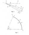
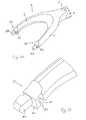
- Figure 1 shows a razor, viewed from the bottom or underside, which is the side facing the skin during shaving;
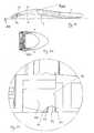
- Figure 2 is a perspective view of the razor, viewed from above, with the razor head and handle separated;
- Figure 3 is a side view of the razor;
- Figure 4 is an enlarged section taken on line IV-IV in Figure 3;
- Figure 5 is an exploded perspective view of the razor head, viewed from the underside;
- Figure 6 is an enlarged cross-section through the razor head;
- Figure 7 is a bottom view of the blade members and flexible blade separators;
- Figure 8 is an enlarged section taken on line VIII-VIII in Figure 7;
- Figure 9 is a perspective view corresponding to Figure 7;
- Figure 10 is an enlarged side view of the cutting edge portion of one of the blade members;
- Figure 11 is a cross-section through an individual one of the blade members;
- Figure 12 is a perspective view of a first, lower part of the razor head, seen from below;
- Figure 13 is a bottom plan view of the first part;
- Figure 14 is an enlarged section taken on line XIV-XIV in Figure 13;
- Figure 15 is a bottom plan view of a second, upper part of the razor head;
- Figure 16 is an enlarged section taken on line XVI-XVI in Figure 15;
- Figure 17 is an end view of the second part;
- Figure 18 is a section taken on line XVIII-XVIII in Figure 17;
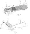
- Figure 19 is a side view of the razor;
- Figure 20 is a section taken on line XX-XX in Figure 19;
- Figure 21 is an enlarged view of the detail XXI indicated in Figure 20;
- Figure 22 is a view similar to Figure 20, but with detent elements disengaged from undercut apertures in the razor head;
- Figure 23 is an enlarged view of the detail XXIII-XXIII indicated in Figure 22;
- Figure 24 is a view similar to Figures 20 and 22, but with the disengaged detents withdrawn from the undercut apertures;
- Figure 25 is an enlarged view of the detail XXV-XXV indicated in Figure 24;
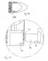
- Figure 26 is a perspective view of the forked end portion of the handle, seen from below, with grooved parts uncovered;
- Figure 27 is an enlarged view of the detail XXVII-XXVII indicated in Figure 26;
- Figure 28 is a cross-section through the razor head and one fork arm of the handle;
- Figure 29 is a side view corresponding to Figure 28, but with the head pivoted to its maximum practical extent; and
- Figures 30 to 32 are similar to Figures 26 to 28, respectively, but show another embodiment of the razor handle.
- The drawings illustrate the presently preferred embodiment of a razor. It is to be noted that the drawings are not to scale.
- The razor comprises a
forked handle 1 and areplaceable head 2. Thehandle 1, which is used to draw the head across the user's skin, has a gentlycurved shank 3, the front end of which merges into the forkedfront end portion 4 which is generally U shaped and has a pair offork arms 6 which are mirror-symmetrical with respect to an imaginary plane longitudinally bisecting theshank 3. By squeezing thearms 6 it is possible to push them inwards slightly; in Figure 1 the normal position of onearm 6 is shown in broken line at the left-hand side, whereas an inwardly pushed position of both of thearms 6 is shown in solid line. Thearms 6 are resiliently flexible, so that they naturally return to their normal position. - The
razor head 2 includes threeblade members 7 which are identical to each other and each made of a single sheet of material, which maybe a metallic, ceramic, or metalloceramic material. Alternatively, a blade member may be made of separate parts joined together, e.g. a front part containing a cutting edge and a rear part connected to the front part. Eachblade member 7 has a straightfront cutting edge 8 and a rear edge parallel to it. Apart from the sharpenedportion 11 with thecutting edge 8, theblade member 7 is of constant thickness in the embodiment illustrated. - The
cutting edges 8 lie in acutting plane 12 and are mutually parallel in the embodiment illustrated. Eachblade member 7 has a convexouter surface 13 facing towards thecutting plane 12 and an opposite concaveinner surface 14. An imaginary median surface 16 (Figure 10), mid-way between the outer andinner surfaces cutting plane 12 and is in the form of a segment of a circular cylinder in the embodiment illustrated. The angle α between themedian surface 16 and thecutting plane 12, at thecutting edge 8, is preferably at least 15° and preferably at most 30°, being for example 20°. The segment angle β is preferably in the range from 50° to 75°, more preferably 60° to 70°. - The
blade members 7 are identically curved and are arranged parallel to one another. This arrangement facilitates the passage of waste material (hair follicles and shaving lotion) through the head (past the concave side and the convex side of each blade) and can prevent excess build up of waste which would tend to raise thecutting edges 8 from the shaving surface. To enhance this effect, the spacing between therear edges 9 could be made greater than that between thecutting edges 8. The curvature of the blade members allows the sharpenedportions 11 to be offered up to the shaving surface at an optimum angle, while the blade members direct the waste material away from the shaving surface. The curved profile of the blade member enhances its longitudinal strength and minimises deformation of the cutting edge during use. - The
blade members 7 are held between a first, lower head part 17 (which is adjacent the skin during shaving) and a second,upper head part 18. Thehead parts curved blade members 7 between them, the curvature of thesupports blade members 7. - The
first head part 17 is in the form of a frame defining anopening 22 through which thecutting edges 8 of theblade members 7 are accessible. The frame includes a leadingelement 23 in the form of a hair erection strip which is provided with africtional surface 24 having a higher coefficient of friction than the remaining surfaces of the frame and tending to pull the skin taut and erecting the hair follicles in its path as therazor head 2 is drawn across the skin during shaving. Both the leadingelement 23 of the frame and the trailingelement 26 haverespective gutters ducts 29 communicate between thegutter 28 and theopening 22, keeping thegutter 28 well supplied with shaving solution during shaving. - The frame also includes lateral elements in the form of raised
skids 31, which assist in flattening the shaving surface during use. As best seen in Figure 6, the plane of the shavingsurface 32 tangential to the frame-formingelements plane 12 with respect to theblade members 7, thereby assisting in correct location of thecutting edges 8 in relation to the shaving surface. As best seen in Figure 3, theelongate handle 1 is angled away from the plane of the shavingsurface 32, thefront end portion 4 curving away from that plane. For example, the angle between the median longitudinal axis of theshaft 3 and the shavingsurface 32 may be in the range from 30° to 50°, in particular about 40°. This helps the user to present therazor head 2 to the skin. In combination with the forkedfront end portion 4, this is particularly convenient in use. - The
second head part 18 is in the form of a frame having front andrear members side members 36. Bridgingmembers rear members middle bridging members 38 and theside members 36 carry resiliently flexible blade supports orspacers 39 which maintain a constant spacing between theblade members 7 and minimise deformation of the blade members during shaving. Eachflexible spacer 39 is in the form of an elongate element or finger carried by a relativelyrigid pin 40, this structure being produced by two-shot moulding, for example. Bothhead parts - Preferably, each of the first and
second head parts hair erection strip 23 to be a separate piece. In another embodiment, the twohead parts head parts - The rear end of each
side member 36 of thesecond part 18 of therazor head 2 has an undercutaperture 42 in a planarrear abutment surface 43. The distal ends of thefork arms 6 havedetent elements 44 projecting forwardly from front abutment surfaces 46, which are also planar. Eachdetent element 44 has ashoulder 47 which engages against an undercutsurface 48 in theaperture 42, while the front and rear abutment surfaces 43, 46 abut against one another; in this way therazor head 2 is fixed relative to the distal ends of thefork arms 6. This situation is illustrated in Figures 19 to 21. - In order to release the
razor head 2 from thehandle 1, thefork arms 6 are first squeezed towards each other, so that theshoulders 48 of thedetent elements 44 are disengaged from the undercut surfaces 48 inside theapertures 42, as shown in Figures 22 and 23. Then thedetent elements 44 are withdrawn from the undercutapertures 42, as shown in Figures 24 and 25. - Although the
razor head 2 is fixed in relation to the distal ends of thefork arms 6, it is desirable for the head to be able to pivot relative to theshank 3 about an axis parallel to thecutting edges 8 when a pivoting force is applied to the razor head during shaving. For this purpose, eachfork arm 6 has atransverse groove 49, which leaves anintegral hinge 51. Thegrooves 49 are mutually aligned on the same side of the forkedend portion 4 of thehandle 1. Thearm portion 52 including thegroove 49 and thedetent element 44 may be integral with the remainder of thefork arm 6 or (as shown in Figure 28) may be a separate part having astub 53 fixed in the remaining part of thefork arm 6. - The part containing the
groove 49 is encased in a resiliently deformable material 54 (such as a thermoplastic elastomer) which adheres to the surfaces of the flexible part. As can be seen from Figure 28, for example, thematerial 54 defines part of thefront abutment surface 46. The resiliently deformable material in thegroove 49 is stretched when a pivoting force is applied to therazor head 2 during shaving (allowing thegroove 49 to open and therazor head 2 to pivot) and restores therazor head 2 to its normal position when the force is removed. - The
groove 49 occupies approximately 3/4 to 4/5 of the depth of thearm portion 52 and has afront wall 56 approximately parallel with theabutment surface 46, arear wall 57 sloping away from thefront wall 56, and arounded base 58. The extensibility of thematerial 54 is such that thehead 2 is pivotable relative to thehandle 1, under normal shaving forces, through an angle γ of up to at least 45°, for example, as shown in Figure 29, preferably up to 65°. - The
shaft 3 of thehandle 1 is provided with agrip area 59, which extends around theshaft 3. Thegrip area 59 has a plurality ofsmall protuberances 61 to aid gripping. Thegrip area 59 may be made of a different material from the remainder of theshaft 3 and, in particular, may be softer and may have a higher coefficient friction. The body of thehandle 1, including thearms 6, may be made of a resilient deformable material so that thearms 6, as a whole, can be flexed towards each other by squeezing the forkedportion 4 between finger and thumb. However, the body of thehandle 1 may be made of a relatively rigid material, in which case eachfork arm 6 may comprise a relatively flexible distal portion which is fixed to the relatively rigid proximal portion and contains thegroove 49. A basic handle moulding can be made out of any suitable material, for example thermoplastic elastomer, polypropylene, styrene or styrene-copolymer plastics, cast metal such as aluminium, or composite material such as carbon fibre. A handle made of thermoplastic elastomer could have a grip area made of a softer thermoplastic elastomer (e.g. by two-shot injection moulding). A handle produced from carbon fibre may have a grip area made of aluminium or wood, for example. - In the alternative embodiment illustrated in Figures 30 to 32, the
grooves 49 are provided on the upper side of thefront end portion 4 of thehandle 1, so that the resilientlydeformable material 54 in eachgroove 49 undergoes compression when the pivoting force is applied. - Various modifications may be made within the scope of the invention. For instance, although the razor blade has been described as having three blade members, which is the preferred number, it may be possible to use a single blade member, a pair of blade members, or four or more blade members. The cutting edges may be angled with respect to one another. The blade members may be of variable thickness. The radius of curvature may vary, in particular it may decrease in the direction away from the cutting edge. Instead of curved blade members, it may be possible to use straight blade members or bent blade members. Instead of blade members which are formed with an inherent (permanent) curvature and are mounted in the head on support surfaces with the same curvature (as described above), it may be possible to use inherently straight blade members which are sufficiently flexible to be bent to the required curvature upon mounting in the head. The razor head may be permanently fixed to the handle, in which case the blade members may be replaceably arranged or the razor as a whole may be disposable.
Claims (10)
- A razor handle, for a razor including a razor head having at least one blade member with a cutting edge extending along a head axis transverse to a handle axis, the razor handle (1) having a front end portion (4), the distal end of which is connectable or connected to the razor head,characterised in that the front end portion is a forked front end portion (4) with a pair of fork arms (6), the distal ends of which are connectable or connected to the razor head (21) at positions adjacent the respective ends of the razor head, each fork arm (6) having a groove (49) allowing pivoting of the distal end about a pivot axis parallel to the head axis, the grooves (49) being mutually aligned on the same side of the forked end portion (4) of the handle, each groove (49) being substantially filled with a resiliently deformable material (54) which is deformed when a pivoting force is applied to the distal ends by the razor head during shaving and which restores the distal ends to a normal position when the force is removed.
- A razor handle as claimed in claim 1, wherein the resiliently deformable material (54) in the groove (49) undergoes extension when the pivoting force is applied.
- A razor handle as claimed in claim 1 or 2, wherein the resiliently deformable material (54) encases a part of the front end portion (4) containing the groove (49).
- A razor handle as claimed in any preceding claim, wherein the resiliently deformable material (54) is a thermoplastic elastomer.
- A razor handle as claimed in any preceding claim, wherein the distal ends of the fork arms (6) have detent elements (44) engageable in undercut apertures (42) in the razor head (2), the distal ends of the fork arms (6) being movable toward one another to disengage the detent elements (44) and allow them to be removed from the undercut apertures (42).
- A razor handle as claimed in claim 5, wherein each fork arm (6) comprises a relatively rigid proximal portion and a relatively flexible distal portion which is fixed to the proximal portion and contains the groove (49).
- A razor comprising a razor head (2) and a razor handle (1) according to any preceding claim.
- A razor as claimed in claim 7, the razor handle (1) being in accordance with claim 5, the razor head (2) having undercut apertures (42) in rear abutment surfaces (43), the detent elements (44) projecting forwardly from front abutment surfaces (46) of the fork arms (6), the front and rear abutment surfaces (43, 46) abutting against one another and the detent elements (44) engaging in the undercut apertures (42) in such a manner that the razor head (2) is fixed relative to the distal ends of the fork arms (6), the distal ends being movable toward one another to disengage the detent elements (44) from the undercut apertures (42) and allow the razor head (2) to be removed from the handle (1), the distal ends being pivotable about an axis parallel to the head axis when a pivoting force is applied to the razor head (2) during shaving.
- A razor as claimed in claim 7 or 8, wherein the razor head (2) is pivotable relative to the handle (1) through an angle of up to 65°.
- A razor as claimed in any of claims 7 to 9, the razor head (2) defining a shaving surface (32) toward which the cutting edge (8) is directed and a reverse surface opposite the shaving surface, the handle (1) having a front end portion (4) connected to the razor head (2) between the shaving surface (32) and the reverse surface, the handle (1) being angled away from a plane tangential to the shaving surface (32), the front end portion (4) preferably curving away from the said plane.
Priority Applications (4)
| Application Number | Priority Date | Filing Date | Title |
|---|---|---|---|
| PL06005226TPL1674220T3 (en) | 2003-11-17 | 2004-11-10 | Razor Handle |
| EP20070021773EP1892067B1 (en) | 2003-11-17 | 2004-11-10 | Razor handle |
| PL07021773TPL1892067T3 (en) | 2003-11-17 | 2004-11-10 | Razor handle |
| EP20100180791EP2292391B1 (en) | 2003-11-17 | 2004-11-10 | Razor |
Applications Claiming Priority (2)
| Application Number | Priority Date | Filing Date | Title |
|---|---|---|---|
| GB0326772AGB2408010B (en) | 2003-11-17 | 2003-11-17 | Shaving product |
| EP20040256976EP1531030B1 (en) | 2003-11-17 | 2004-11-10 | Razor |
Related Parent Applications (1)
| Application Number | Title | Priority Date | Filing Date |
|---|---|---|---|
| EP20040256976DivisionEP1531030B1 (en) | 2003-11-17 | 2004-11-10 | Razor |
Related Child Applications (1)
| Application Number | Title | Priority Date | Filing Date |
|---|---|---|---|
| EP20070021773DivisionEP1892067B1 (en) | 2003-11-17 | 2004-11-10 | Razor handle |
Publications (2)
| Publication Number | Publication Date |
|---|---|
| EP1674220A1 EP1674220A1 (en) | 2006-06-28 |
| EP1674220B1true EP1674220B1 (en) | 2008-01-02 |
Family
ID=29763965
Family Applications (4)
| Application Number | Title | Priority Date | Filing Date |
|---|---|---|---|
| EP20100180791Expired - LifetimeEP2292391B1 (en) | 2003-11-17 | 2004-11-10 | Razor |
| EP20070021773Expired - LifetimeEP1892067B1 (en) | 2003-11-17 | 2004-11-10 | Razor handle |
| EP20040256976Expired - LifetimeEP1531030B1 (en) | 2003-11-17 | 2004-11-10 | Razor |
| EP20060005226Expired - LifetimeEP1674220B1 (en) | 2003-11-17 | 2004-11-10 | Razor Handle |
Family Applications Before (3)
| Application Number | Title | Priority Date | Filing Date |
|---|---|---|---|
| EP20100180791Expired - LifetimeEP2292391B1 (en) | 2003-11-17 | 2004-11-10 | Razor |
| EP20070021773Expired - LifetimeEP1892067B1 (en) | 2003-11-17 | 2004-11-10 | Razor handle |
| EP20040256976Expired - LifetimeEP1531030B1 (en) | 2003-11-17 | 2004-11-10 | Razor |
Country Status (8)
| Country | Link |
|---|---|
| US (2) | US7100284B2 (en) |
| EP (4) | EP2292391B1 (en) |
| AT (3) | ATE376912T1 (en) |
| DE (3) | DE602004031057D1 (en) |
| ES (3) | ES2299112T3 (en) |
| GB (1) | GB2408010B (en) |
| PL (3) | PL1892067T3 (en) |
| PT (2) | PT1674220E (en) |
Families Citing this family (118)
| Publication number | Priority date | Publication date | Assignee | Title |
|---|---|---|---|---|
| GB2354474B8 (en)* | 1999-09-27 | 2008-01-29 | Gillette Co | Safety razors |
| US6916035B2 (en) | 2001-01-23 | 2005-07-12 | Russell A. Houser | Athletic devices and other devices with superelastic components |
| US7690122B2 (en)* | 2004-03-11 | 2010-04-06 | The Gillette Company | Shaving razor with button |
| BRPI0519884B1 (en)* | 2005-02-03 | 2019-08-06 | Bic-Violex Sa | Shaving Cord & Shaver |
| WO2006081838A1 (en)* | 2005-02-03 | 2006-08-10 | Bic-Violex Sa | Razor handle having an arcuate profile |
| US20080189964A1 (en)* | 2005-02-03 | 2008-08-14 | Bic-Violex Sa | Razor Handle Having Reticulated Head Portion |
| US20080148579A1 (en)* | 2005-02-03 | 2008-06-26 | Bic-Violex Sa | Razor Handling Having an Air Cushion Finger Rest Area |
| BRPI0519867B1 (en)* | 2005-02-03 | 2019-03-19 | Bic-Violex Sa | Shaving Cord |
| EP1896225B1 (en)* | 2005-06-28 | 2011-03-30 | BIC Violex S.A. | Razor handle provided with an improved grip |
| KR101257785B1 (en)* | 2005-06-28 | 2013-04-24 | 빅-비올렉스 에스아 | Improvements to razor handle grips |
| US8256532B2 (en)* | 2005-07-01 | 2012-09-04 | Board Of Regents, The University Of Texas System | System, program products, and methods for controlling drilling fluid parameters |
| KR100749925B1 (en)* | 2006-06-29 | 2007-08-16 | 주식회사 도루코 | Shaver |
| FR2909025B1 (en)* | 2006-11-28 | 2009-07-10 | Carlos Ribeiro | MECHANICAL RAZOR. |
| GB0716941D0 (en)* | 2007-08-31 | 2007-10-10 | Knowledge & Merchandising Inc | Razor handle |
| US8544177B2 (en)* | 2007-11-02 | 2013-10-01 | The Gillette Company | Razor with rearwardly secured shaving blade member |
| USD589210S1 (en) | 2008-01-11 | 2009-03-24 | American Safety Razor | Shaving razor |
| US7665199B2 (en)* | 2008-01-23 | 2010-02-23 | The Gillette Company | Method of making a razor blade unit |
| USD611654S1 (en)* | 2008-01-28 | 2010-03-09 | Kai R & D Center Co., Ltd. | Safety razor holder |
| PL2276591T3 (en)* | 2008-05-05 | 2013-11-29 | Eveready Battery Inc | Method of making a razor blade |
| USD593251S1 (en)* | 2008-05-09 | 2009-05-26 | Knowledge & Merchandising Inc. | Razor handle |
| ATE547213T1 (en)* | 2008-05-22 | 2012-03-15 | Feintechnik Gmbh Eisfeld | RAZOR BLADE UNIT WITH CUTTING EDGE BEARING |
| EP2123410B1 (en)* | 2008-05-23 | 2011-07-27 | Feintechnik GmbH Eisfeld | Razor blade unit with film hinge |
| US10391652B2 (en)* | 2008-05-30 | 2019-08-27 | The Gillette Company Llc | Blade support for multi-blade razor cartirdges |
| GB2461054A (en)* | 2008-06-18 | 2009-12-23 | Knowledge & Merchandising Inc | Razor handle with predetermined spring index |
| EP2307188B2 (en)* | 2008-07-18 | 2018-09-12 | BIC-Violex S.A. | Process for manufacturing a safety razor cartridge, and safety razor cartridge |
| US9221185B2 (en)* | 2008-09-10 | 2015-12-29 | The Gillette Company | Shaving razors and cartridges |
| MX2011003331A (en)* | 2008-09-29 | 2011-04-26 | Gillette Co | Razors and razor cartridges with a decreased total interblade span. |
| EP2349658B1 (en)* | 2008-09-29 | 2013-03-06 | The Gillette Company | Razor cartridges with perforated blade assemblies |
| US8234789B2 (en)* | 2008-10-29 | 2012-08-07 | The Gillette Company | Razor with floatably secured shaving blade member |
| RU2008150012A (en)* | 2008-12-10 | 2010-06-20 | Александр Тарасович Володин (RU) | SAFETY RAZOR BLADE BLOCK |
| KR20100091622A (en)* | 2009-02-11 | 2010-08-19 | 주식회사 도루코 | Integrated cartridge |
| KR101055684B1 (en)* | 2009-02-11 | 2011-08-09 | 주식회사 도루코 | Integrated razor blades and razor cartridges using the same |
| EP2218559B1 (en)* | 2009-02-13 | 2012-08-15 | Trisa Holding AG | Body care device |
| US20110016724A1 (en)* | 2009-07-24 | 2011-01-27 | Matthew Frank Murgida | Resilient Skin Contacting Members to Facilitate Pivoting |
| US8273205B2 (en) | 2009-07-24 | 2012-09-25 | The Gillette Company | Manufacture of pivoting resilient skin contacting members |
| CN201446542U (en)* | 2009-08-06 | 2010-05-05 | 任向荣 | Razor head and outer frame body |
| KR20110024234A (en)* | 2009-09-01 | 2011-03-09 | 주식회사 도루코 | Shaver cartridges |
| DE102009050344A1 (en)* | 2009-10-22 | 2011-05-05 | Mebus Mim-Technik Gmbh | Wet-shaving device has shaft-shaped handle, blade and shaving head pivotable around axis, where shaving head is held magnetically at handle |
| US20120192431A9 (en)* | 2009-11-18 | 2012-08-02 | Kevin James Wain | Blades for Shaving Razors |
| US20110119923A1 (en)* | 2009-11-20 | 2011-05-26 | Roy Nicoll | Razors and kits for applying shaving aids |
| US20110162209A1 (en)* | 2010-01-06 | 2011-07-07 | Kevin James Wain | Blades for Shaving Razors |
| USD662662S1 (en)* | 2010-03-11 | 2012-06-26 | Ian Rumsey | Handle |
| US8359752B2 (en) | 2010-06-17 | 2013-01-29 | The Gillette Company | Shaving razor cartridge |
| PL2588282T3 (en) | 2010-06-29 | 2019-09-30 | Edgewell Personal Care Brands, Llc | Razor handle |
| US8413334B2 (en)* | 2010-08-03 | 2013-04-09 | The Gillette Company | Shaving cartridge guard for supporting skin |
| US8448339B2 (en)* | 2010-08-03 | 2013-05-28 | The Gillette Company | Shaving cartridge with supressed blade geometry |
| GB201015674D0 (en)* | 2010-09-20 | 2010-10-27 | King Of Shaves Company The Ltd | Razor system |
| US8732955B2 (en) | 2010-10-20 | 2014-05-27 | The Gillette Company | Shaving razor including a biasing member producing a progressively increasing cartridge return torque |
| US8650763B2 (en) | 2010-10-20 | 2014-02-18 | The Gillette Company | Shaving razor providing enhanced control during shaving |
| US8769825B2 (en) | 2010-10-20 | 2014-07-08 | The Gillette Company | Shaving razor including a biasing member producing a progressively increasing cartridge return torque and handle geometry enhancing control during shaving |
| US8881406B2 (en)* | 2011-05-17 | 2014-11-11 | Abraham Glezerman | Shaving device with dual cutting elements |
| US9144914B2 (en) | 2011-06-30 | 2015-09-29 | Rolling Razor, Inc. | Razor cartridge with reduced part count and expanded range of motion |
| US20130081291A1 (en)* | 2011-09-30 | 2013-04-04 | Kevin James Wain | Biasing shaving razors |
| BR112014007708B1 (en) | 2011-10-06 | 2020-09-15 | Bic-Violex Sa | RIGID SHAVING OR SHAVING BLADE FORMED INTEGRALLY AND SHAVING OR SHAVING HEAD |
| US20140000114A1 (en)* | 2012-06-28 | 2014-01-02 | The Gillette Company | Shaving razor cartridge |
| US9283685B2 (en) | 2012-07-26 | 2016-03-15 | Shavelogic, Inc. | Pivoting razors |
| US9486930B2 (en) | 2012-09-27 | 2016-11-08 | Shavelogic, Inc. | Shaving systems |
| WO2014051842A1 (en) | 2012-09-27 | 2014-04-03 | Shavelogic, Inc. | Shaving systems |
| WO2014051843A1 (en) | 2012-09-28 | 2014-04-03 | Shavelogic, Inc. | Shaving systems |
| GB2507971A (en)* | 2012-11-14 | 2014-05-21 | King Of Shaves Company Ltd | Razor with releasably attachable disposable cartridge |
| US9623575B2 (en)* | 2012-12-18 | 2017-04-18 | Shavelogic, Inc. | Shaving systems |
| US9457486B2 (en) | 2013-03-13 | 2016-10-04 | Rolling Razor, Inc | Shaving cartridge with individual blade guards |
| EP2823942A1 (en)* | 2013-07-10 | 2015-01-14 | The Gillette Company | Razor cartridges |
| DE102013213859A1 (en)* | 2013-07-16 | 2015-01-22 | Beiersdorf Ag | Razor in bowl shape |
| USD729452S1 (en)* | 2013-07-30 | 2015-05-12 | Shavelogic, Inc. | Razor |
| USD729453S1 (en)* | 2013-07-30 | 2015-05-12 | Shavelogic, Inc. | Razor |
| USD729454S1 (en)* | 2013-07-30 | 2015-05-12 | Shavelogic, Inc. | Razor |
| PL3077165T3 (en)* | 2013-12-05 | 2020-08-10 | Bic-Violex S.A. | A shaving blade cartridge |
| US20150158192A1 (en) | 2013-12-09 | 2015-06-11 | Shavelogic, Inc. | Multi-material pivot return for shaving systems |
| CA2932764C (en) | 2013-12-18 | 2020-01-14 | Bic-Violex Sa | A shaving blade cartridge |
| US10562199B2 (en)* | 2014-01-15 | 2020-02-18 | The Gillette Company Llc | Connecting member |
| US9873206B2 (en) | 2014-03-13 | 2018-01-23 | Karl O. Gulledge | Interchangeable shaver |
| US9616584B2 (en)* | 2014-03-20 | 2017-04-11 | Rolling Razor, Inc. | Shaving razor and shaving handle with an interconnection mechanism |
| WO2015142663A1 (en) | 2014-03-21 | 2015-09-24 | Shavelogic, Inc. | Metal spring return |
| US11148310B2 (en) | 2014-03-24 | 2021-10-19 | Flexhandle, L.L.C. | Razor with handle having articulable joint |
| US9498891B2 (en)* | 2014-04-21 | 2016-11-22 | Heated Blades Holding Company, Llc | Razor cartridge with unitary heated blade arrangement |
| WO2016032014A1 (en)* | 2014-08-25 | 2016-03-03 | 주식회사 도루코 | Razor blade and razor cartridge using same |
| EP3237155B1 (en) | 2014-12-24 | 2020-06-10 | BIC-Violex S.A. | A shaving blade cartridge and a shaver comprising such shaving blade cartridge |
| RU2694395C1 (en) | 2015-12-01 | 2019-07-12 | Бик-Виолекс Са | Shaving machines and cartridges |
| PL3383603T3 (en)* | 2015-12-01 | 2021-12-13 | Bic Violex S.A. | Shaving razors and shaving cartridges |
| US10652956B2 (en) | 2016-06-22 | 2020-05-12 | The Gillette Company Llc | Personal consumer product with thermal control circuitry and methods thereof |
| KR101730415B1 (en)* | 2016-06-24 | 2017-04-26 | 주식회사 도루코 | Razor with perforated handle |
| US20180043555A1 (en)* | 2016-08-11 | 2018-02-15 | The Gillette Company | Handle for a razor |
| EP3351358B1 (en) | 2017-01-20 | 2019-11-20 | The Gillette Company LLC | Heating delivery element for a shaving razor |
| USD824106S1 (en)* | 2017-02-07 | 2018-07-24 | Spectrum Brands, Inc. | Trimmer |
| USD822903S1 (en)* | 2017-02-07 | 2018-07-10 | Spectrum Brands, Inc. | Trimmer |
| EP3372358B2 (en) | 2017-03-10 | 2025-07-09 | The Gillette Company LLC | Razor handle |
| KR102447658B1 (en)* | 2017-07-20 | 2022-09-26 | 쉐이브로직, 인코포레이티드 | shaving system |
| MX2020000759A (en)* | 2017-07-20 | 2020-08-17 | Shavelogic Inc | Shaving systems. |
| KR101925281B1 (en)* | 2017-11-29 | 2018-12-06 | 주식회사 도루코 | Razor cartridge and razor cartridge assembly |
| US11541560B2 (en) | 2018-03-01 | 2023-01-03 | Rolling Razor, Inc. | Precision razor with low cost assembly |
| US11607820B2 (en) | 2018-03-30 | 2023-03-21 | The Gillette Company Llc | Razor handle with movable members |
| CN111819048A (en) | 2018-03-30 | 2020-10-23 | 吉列有限责任公司 | Razor handle with pivoting portion |
| USD874061S1 (en) | 2018-03-30 | 2020-01-28 | The Gillette Company Llc | Shaving razor cartridge |
| EP3774227A1 (en) | 2018-03-30 | 2021-02-17 | The Gillette Company LLC | Razor handle with movable members |
| EP3774221A1 (en) | 2018-03-30 | 2021-02-17 | The Gillette Company LLC | Razor handle with a pivoting portion |
| CN112243403B (en) | 2018-03-30 | 2022-06-17 | 吉列有限责任公司 | Razor handle with pivoting portion |
| CN111801205B (en) | 2018-03-30 | 2022-08-23 | 吉列有限责任公司 | Razor handle with pivoting portion |
| WO2019191163A1 (en)* | 2018-03-30 | 2019-10-03 | The Gillette Company Llc | Razor handle with a pivoting portion |
| WO2019190962A1 (en) | 2018-03-30 | 2019-10-03 | The Gillette Company Llc | Razor handle with a pivoting portion |
| EP3774215B1 (en) | 2018-03-30 | 2024-03-13 | The Gillette Company LLC | Razor handle with a pivoting portion |
| CA3092879A1 (en) | 2018-03-30 | 2019-10-03 | The Gillette Company Llc | Razor handle with movable members |
| US10773408B2 (en) | 2018-03-30 | 2020-09-15 | The Gillette Company Llc | Shaving razor cartridge |
| EP3546156B1 (en) | 2018-03-30 | 2021-03-10 | The Gillette Company LLC | Razor handle with a pivoting portion |
| JP7104168B2 (en) | 2018-03-30 | 2022-07-20 | ザ ジレット カンパニー リミテッド ライアビリティ カンパニー | Razor handle with pivot part |
| JP2021515672A (en) | 2018-03-30 | 2021-06-24 | ザ ジレット カンパニー リミテッド ライアビリティ カンパニーThe Gillette Company Llc | Razor system for shaving |
| BR112020020132A2 (en) | 2018-03-30 | 2021-01-05 | The Gillette Company Llc | HANDLE OF SHAVING OR DEVILING APPLIANCE WITH MOBILE LIMBS |
| US11345055B2 (en) | 2018-09-05 | 2022-05-31 | The Gillette Company Llc | Razor cartridge structure |
| US11298842B2 (en)* | 2018-09-05 | 2022-04-12 | The Gillette Company Llc | Razor structure |
| EP3919242B1 (en)* | 2019-01-29 | 2024-08-21 | Wenzhou Mers R&D Ltd. | Shaving razor head |
| US11035130B1 (en) | 2019-02-01 | 2021-06-15 | Daniel Efrain Arguelles | Synthetic mechanically attached roof underlayment system |
| US11273563B2 (en)* | 2019-07-30 | 2022-03-15 | Bic Violex S.A. | Self-movable blade supports |
| JP6600762B1 (en) | 2019-07-31 | 2019-10-30 | 株式会社貝印刃物開発センター | Razor head |
| WO2021019794A1 (en)* | 2019-07-31 | 2021-02-04 | 株式会社貝印刃物開発センター | Razor head |
| EP3797947B1 (en)* | 2019-09-25 | 2024-09-04 | BIC Violex Single Member S.A. | Razor cartridge |
| KR102343058B1 (en)* | 2019-12-10 | 2021-12-24 | 주식회사 도루코 | Razor Cartridge |
| WO2022159651A1 (en)* | 2021-01-21 | 2022-07-28 | Rk Inventions, Llc | Razor with intermittent encapsulation of embedded blades |
| EP4197724A1 (en)* | 2021-12-14 | 2023-06-21 | BIC Violex Single Member S.A. | Razor cartridges |
Family Cites Families (58)
| Publication number | Priority date | Publication date | Assignee | Title |
|---|---|---|---|---|
| US1024509A (en)* | 1909-11-13 | 1912-04-30 | Herbert C Harrison | Multibladed razor. |
| US1423414A (en)* | 1919-07-10 | 1922-07-18 | John F Blything | Safety razor |
| FR821030A (en)* | 1936-08-01 | 1937-11-25 | Safety razor enhancements | |
| US2119405A (en)* | 1936-10-21 | 1938-05-31 | Runcie Walter Osborne | Safety razor |
| FR973077A (en) | 1948-10-07 | 1951-02-07 | Advanced safety razors | |
| FR1060261A (en)* | 1951-07-17 | 1954-03-31 | Mechanical razor | |
| CH378722A (en)* | 1963-07-31 | 1964-06-15 | Climar Ag | razor |
| US3407496A (en)* | 1966-06-22 | 1968-10-29 | William R. Pomper | Razor having a plurality of blade edges of different contours |
| US3657810A (en)* | 1968-10-09 | 1972-04-25 | Gillette Co | Razor |
| US3777396A (en)* | 1972-06-01 | 1973-12-11 | Warner Lambert Co | Cartridges having tandemly mounted cutting edges on two sides thereof |
| US3892036A (en)* | 1973-06-04 | 1975-07-01 | Gillette Co | Safety razor |
| US3842502A (en)* | 1973-12-21 | 1974-10-22 | Warner Lambert Co | Shaving unit for safety razor |
| US4057896A (en)* | 1975-05-12 | 1977-11-15 | The Gillette Company | Razor handle |
| GB2030909A (en)* | 1978-08-15 | 1980-04-16 | Wilkinson Sword Ltd | Razors |
| GB2055069B (en) | 1979-08-01 | 1983-05-05 | Wilkinson Sword Ltd | Shaving units |
| US4392303A (en)* | 1979-12-31 | 1983-07-12 | Warner-Lambert Company | One-piece razor handle |
| US4459744A (en)* | 1982-02-04 | 1984-07-17 | Alan K. Roberts | Razor blade apparatus and method |
| US4587729A (en)* | 1982-09-17 | 1986-05-13 | The Gillette Company | Safety razor |
| IT1198503B (en)* | 1983-01-14 | 1988-12-21 | Athos Bergamaschi | TWO-BLADE RAZOR HEAD WITH THREE ELEMENTS PRINTED WITHOUT CONTINUITY SOLUTION |
| US4599793A (en)* | 1984-05-23 | 1986-07-15 | American Safety Razor Company | Razor connector |
| GB8506831D0 (en)* | 1985-03-15 | 1985-04-17 | Wilkinson Sword Ltd | Razor handle |
| IL79651A (en)* | 1986-08-07 | 1991-03-10 | America Israel Blades Ltd | Safety razor |
| US4774765A (en)* | 1986-09-02 | 1988-10-04 | Warner-Lambert Company | Blade assembly featuring variable span |
| DE3635553A1 (en)* | 1986-10-20 | 1988-04-21 | Detlef Koeppen | Razor |
| US4797998A (en)* | 1986-12-08 | 1989-01-17 | Warner-Lambert Company | Lockable pivotable razor |
| ATE69191T1 (en)* | 1988-09-08 | 1991-11-15 | Wilkinson Sword Gmbh | RAZOR HEAD, PARTICULARLY RAZOR UNIT. |
| AU638974B2 (en)* | 1989-06-05 | 1993-07-15 | Warner-Lambert Company | Razor mechanism |
| AR244587A1 (en)* | 1989-11-17 | 1993-11-30 | Warner Lambert Co | Pivoting safety razor assembly |
| GB9013047D0 (en)* | 1990-06-12 | 1990-08-01 | Gillette Co | Safety razors |
| EP0594681B1 (en)* | 1991-07-18 | 1998-04-29 | Warner-Lambert Company | Razor head with variable shaving geometry |
| EP0614409A1 (en)* | 1991-11-27 | 1994-09-14 | The Gillette Company | Razors |
| GB2264888B (en)* | 1992-03-06 | 1995-01-25 | Wilkinson Sword Gmbh | Razor head with flow passages |
| GB2265565B (en)* | 1992-03-28 | 1995-03-22 | Wilkinson Sword Gmbh | Razor head of a wet razor |
| US6161288A (en)* | 1993-02-22 | 2000-12-19 | Andrews; Edward A. | Four blade bi-directional razor structure with flexible guard system |
| US5590468A (en)* | 1993-04-16 | 1997-01-07 | American Safety Razor Company | Movable blade shaving cartridge with conditioning bar |
| US5560106A (en)* | 1993-11-09 | 1996-10-01 | Armbruster; Joseph M. | Resilient floating head razor |
| US5537749A (en)* | 1994-06-30 | 1996-07-23 | Cacioppo; Tony | Razor |
| US6944952B1 (en)* | 1994-07-01 | 2005-09-20 | The Gillette Company | Shaving system |
| US5600887A (en)* | 1995-05-26 | 1997-02-11 | Olson; Brad | Flexible easy-rinsing razor |
| US5771591A (en)* | 1995-09-28 | 1998-06-30 | Armbruster; Joseph M. | Disposable resilient razor |
| US6185823B1 (en)* | 1995-11-10 | 2001-02-13 | The Gillette Company | Oval frame razor |
| US5678316A (en)* | 1995-12-15 | 1997-10-21 | Warner-Lambert Company | Disposable razor |
| US5661907A (en)* | 1996-04-10 | 1997-09-02 | The Gillette Company | Razor blade assembly |
| US5787586A (en)* | 1996-04-10 | 1998-08-04 | The Gillette Company | Shaving system and method |
| GB9616299D0 (en)* | 1996-08-02 | 1996-09-11 | Gillette Co | Safety razors |
| CA2235115A1 (en)* | 1997-06-16 | 1998-12-16 | David C. Coffin | Razor providing pivoting and swivelling razor head support |
| GB9715501D0 (en)* | 1997-07-22 | 1997-10-01 | Gillette Co | Safety razors |
| WO1999014020A1 (en)* | 1997-09-18 | 1999-03-25 | The Gillette Company | Safety razors |
| US5953824A (en)* | 1997-09-23 | 1999-09-21 | Warner-Lambert Company | Razors providing pivoting and swivelling razor head support |
| US6035537A (en)* | 1997-09-30 | 2000-03-14 | The Gillette Company | Razor cartridge with metal clip retaining blades |
| US6122826A (en)* | 1998-04-22 | 2000-09-26 | Warner-Lambert Company | Disposable cartridge holder for single direction pivoting cartridge |
| US6161287A (en)* | 1998-04-24 | 2000-12-19 | The Gillette Company | Razor blade system |
| GB9828215D0 (en)* | 1998-12-21 | 1999-02-17 | Gillette Co | Safety razors |
| US6223442B1 (en)* | 1999-08-19 | 2001-05-01 | William Alvarez Pina | Non-motorized razor with spring-supported head |
| KR100669144B1 (en)* | 1999-11-29 | 2007-01-15 | 코닌클리케 필립스 일렉트로닉스 엔.브이. | Shaver with shaving head with sub-frame and main frame |
| CA2356571A1 (en)* | 2000-10-27 | 2002-04-27 | Vincent Cosmo Motta | Shaving systems with handle to razor head attachment mechanism and methods of performing same |
| US20040177519A1 (en)* | 2003-03-14 | 2004-09-16 | Louis D. Tomassetti | Flexible razor and dispenser with pivoting head |
| DE10327739B4 (en)* | 2003-06-18 | 2006-06-08 | Feintechnik Gmbh Eisfeld | Razor blade unit for a razor |
- 2003
- 2003-11-17GBGB0326772Apatent/GB2408010B/ennot_activeExpired - Fee Related
- 2003-12-11USUS10/732,220patent/US7100284B2/ennot_activeExpired - Fee Related
- 2004
- 2004-11-10PTPT06005226Tpatent/PT1674220E/enunknown
- 2004-11-10DEDE200460031057patent/DE602004031057D1/ennot_activeExpired - Lifetime
- 2004-11-10ATAT04256976Tpatent/ATE376912T1/ennot_activeIP Right Cessation
- 2004-11-10EPEP20100180791patent/EP2292391B1/ennot_activeExpired - Lifetime
- 2004-11-10PLPL07021773Tpatent/PL1892067T3/enunknown
- 2004-11-10DEDE200460009738patent/DE602004009738T2/ennot_activeExpired - Lifetime
- 2004-11-10EPEP20070021773patent/EP1892067B1/ennot_activeExpired - Lifetime
- 2004-11-10PLPL04256976Tpatent/PL1531030T3/enunknown
- 2004-11-10DEDE200460011089patent/DE602004011089T2/ennot_activeExpired - Lifetime
- 2004-11-10PTPT04256976Tpatent/PT1531030E/enunknown
- 2004-11-10EPEP20040256976patent/EP1531030B1/ennot_activeExpired - Lifetime
- 2004-11-10ATAT06005226Tpatent/ATE382456T1/ennot_activeIP Right Cessation
- 2004-11-10EPEP20060005226patent/EP1674220B1/ennot_activeExpired - Lifetime
- 2004-11-10ESES06005226Tpatent/ES2299112T3/ennot_activeExpired - Lifetime
- 2004-11-10ESES07021773Tpatent/ES2359730T3/ennot_activeExpired - Lifetime
- 2004-11-10ATAT07021773Tpatent/ATE494993T1/ennot_activeIP Right Cessation
- 2004-11-10ESES04256976Tpatent/ES2295788T3/ennot_activeExpired - Lifetime
- 2004-11-10PLPL06005226Tpatent/PL1674220T3/enunknown
- 2006
- 2006-08-04USUS11/498,825patent/US7669511B2/ennot_activeExpired - Fee Related
Also Published As
| Publication number | Publication date |
|---|---|
| DE602004009738T2 (en) | 2008-08-28 |
| EP1892067A1 (en) | 2008-02-27 |
| GB2408010B (en) | 2007-03-28 |
| EP1892067B1 (en) | 2011-01-12 |
| ATE376912T1 (en) | 2007-11-15 |
| DE602004011089T2 (en) | 2009-01-02 |
| HK1092414A1 (en) | 2007-02-09 |
| DE602004031057D1 (en) | 2011-02-24 |
| US20050102847A1 (en) | 2005-05-19 |
| ATE382456T1 (en) | 2008-01-15 |
| GB0326772D0 (en) | 2003-12-24 |
| EP1674220A1 (en) | 2006-06-28 |
| GB2408010A (en) | 2005-05-18 |
| PL1674220T3 (en) | 2008-06-30 |
| US20070028449A1 (en) | 2007-02-08 |
| EP1531030B1 (en) | 2007-10-31 |
| EP1531030A2 (en) | 2005-05-18 |
| EP2292391B1 (en) | 2013-01-02 |
| DE602004009738D1 (en) | 2007-12-13 |
| PL1531030T3 (en) | 2008-04-30 |
| ES2299112T3 (en) | 2008-05-16 |
| US7100284B2 (en) | 2006-09-05 |
| HK1076769A1 (en) | 2006-01-27 |
| DE602004011089D1 (en) | 2008-02-14 |
| US7669511B2 (en) | 2010-03-02 |
| EP1531030A3 (en) | 2005-08-03 |
| PL1892067T3 (en) | 2011-07-29 |
| PT1674220E (en) | 2008-03-11 |
| ES2295788T3 (en) | 2008-04-16 |
| EP2292391A1 (en) | 2011-03-09 |
| ATE494993T1 (en) | 2011-01-15 |
| ES2359730T3 (en) | 2011-05-26 |
| PT1531030E (en) | 2008-01-16 |
Similar Documents
| Publication | Publication Date | Title |
|---|---|---|
| EP1674220B1 (en) | Razor Handle | |
| AU2006290228B2 (en) | Blade mounting members for a razor cartridge | |
| AU2009296884B2 (en) | Handle for shaving razors having improved grip | |
| US6216345B1 (en) | Glide systems for manual shaving razors | |
| EP1817143A1 (en) | Shaving implement | |
| CN113084878B (en) | Razor or razor handle | |
| CN100560309C (en) | Razor | |
| JP5052473B2 (en) | Razor | |
| WO2007039737A1 (en) | Razor | |
| HK1092414B (en) | Razor handle | |
| HK1076769B (en) | Razor | |
| JP2006314720A (en) | Razor | |
| CN101318335B (en) | Razor | |
| HK1126163A (en) | Razor | |
| EP1204513A1 (en) | Manual shaving razors with glides | |
| HK1197210B (en) | Razor cartridge with reduced part count and expanded range of motion | |
| HK1197210A1 (en) | Razor cartridge with reduced part count and expanded range of motion |
Legal Events
| Date | Code | Title | Description |
|---|---|---|---|
| PUAI | Public reference made under article 153(3) epc to a published international application that has entered the european phase | Free format text:ORIGINAL CODE: 0009012 | |
| AC | Divisional application: reference to earlier application | Ref document number:1531030 Country of ref document:EP Kind code of ref document:P | |
| AK | Designated contracting states | Kind code of ref document:A1 Designated state(s):AT BE BG CH CY CZ DE DK EE ES FI FR GB GR HU IE IS IT LI LU MC NL PL PT RO SE SI SK TR | |
| AX | Request for extension of the european patent | Extension state:AL HR LT LV MK YU | |
| 17P | Request for examination filed | Effective date:20060829 | |
| REG | Reference to a national code | Ref country code:HK Ref legal event code:DE Ref document number:1092414 Country of ref document:HK | |
| AKX | Designation fees paid | Designated state(s):AT BE BG CH CY CZ DE DK EE ES FI FR GB GR HU IE IS IT LI LU MC NL PL PT RO SE SI SK TR | |
| GRAP | Despatch of communication of intention to grant a patent | Free format text:ORIGINAL CODE: EPIDOSNIGR1 | |
| GRAS | Grant fee paid | Free format text:ORIGINAL CODE: EPIDOSNIGR3 | |
| GRAA | (expected) grant | Free format text:ORIGINAL CODE: 0009210 | |
| AC | Divisional application: reference to earlier application | Ref document number:1531030 Country of ref document:EP Kind code of ref document:P | |
| AK | Designated contracting states | Kind code of ref document:B1 Designated state(s):AT BE BG CH CY CZ DE DK EE ES FI FR GB GR HU IE IS IT LI LU MC NL PL PT RO SE SI SK TR | |
| REG | Reference to a national code | Ref country code:GB Ref legal event code:FG4D | |
| REG | Reference to a national code | Ref country code:IE Ref legal event code:FG4D | |
| REG | Reference to a national code | Ref country code:CH Ref legal event code:EP | |
| REF | Corresponds to: | Ref document number:602004011089 Country of ref document:DE Date of ref document:20080214 Kind code of ref document:P | |
| REG | Reference to a national code | Ref country code:RO Ref legal event code:EPE Ref country code:PT Ref legal event code:SC4A Free format text:AVAILABILITY OF NATIONAL TRANSLATION Effective date:20080229 | |
| REG | Reference to a national code | Ref country code:GR Ref legal event code:EP Ref document number:20080400849 Country of ref document:GR Ref country code:SE Ref legal event code:TRGR | |
| REG | Reference to a national code | Ref country code:ES Ref legal event code:FG2A Ref document number:2299112 Country of ref document:ES Kind code of ref document:T3 | |
| PG25 | Lapsed in a contracting state [announced via postgrant information from national office to epo] | Ref country code:SI Free format text:LAPSE BECAUSE OF FAILURE TO SUBMIT A TRANSLATION OF THE DESCRIPTION OR TO PAY THE FEE WITHIN THE PRESCRIBED TIME-LIMIT Effective date:20080102 | |
| REG | Reference to a national code | Ref country code:PL Ref legal event code:T3 | |
| PG25 | Lapsed in a contracting state [announced via postgrant information from national office to epo] | Ref country code:IS Free format text:LAPSE BECAUSE OF FAILURE TO SUBMIT A TRANSLATION OF THE DESCRIPTION OR TO PAY THE FEE WITHIN THE PRESCRIBED TIME-LIMIT Effective date:20080502 Ref country code:LI Free format text:LAPSE BECAUSE OF FAILURE TO SUBMIT A TRANSLATION OF THE DESCRIPTION OR TO PAY THE FEE WITHIN THE PRESCRIBED TIME-LIMIT Effective date:20080102 Ref country code:CH Free format text:LAPSE BECAUSE OF FAILURE TO SUBMIT A TRANSLATION OF THE DESCRIPTION OR TO PAY THE FEE WITHIN THE PRESCRIBED TIME-LIMIT Effective date:20080102 Ref country code:FI Free format text:LAPSE BECAUSE OF FAILURE TO SUBMIT A TRANSLATION OF THE DESCRIPTION OR TO PAY THE FEE WITHIN THE PRESCRIBED TIME-LIMIT Effective date:20080102 | |
| REG | Reference to a national code | Ref country code:CH Ref legal event code:PL | |
| PG25 | Lapsed in a contracting state [announced via postgrant information from national office to epo] | Ref country code:AT Free format text:LAPSE BECAUSE OF FAILURE TO SUBMIT A TRANSLATION OF THE DESCRIPTION OR TO PAY THE FEE WITHIN THE PRESCRIBED TIME-LIMIT Effective date:20080102 Ref country code:BG Free format text:LAPSE BECAUSE OF FAILURE TO SUBMIT A TRANSLATION OF THE DESCRIPTION OR TO PAY THE FEE WITHIN THE PRESCRIBED TIME-LIMIT Effective date:20080402 | |
| REG | Reference to a national code | Ref country code:HK Ref legal event code:GR Ref document number:1092414 Country of ref document:HK | |
| REG | Reference to a national code | Ref country code:HU Ref legal event code:AG4A Ref document number:E003367 Country of ref document:HU | |
| PLBI | Opposition filed | Free format text:ORIGINAL CODE: 0009260 | |
| PG25 | Lapsed in a contracting state [announced via postgrant information from national office to epo] | Ref country code:SK Free format text:LAPSE BECAUSE OF FAILURE TO SUBMIT A TRANSLATION OF THE DESCRIPTION OR TO PAY THE FEE WITHIN THE PRESCRIBED TIME-LIMIT Effective date:20080102 Ref country code:DK Free format text:LAPSE BECAUSE OF FAILURE TO SUBMIT A TRANSLATION OF THE DESCRIPTION OR TO PAY THE FEE WITHIN THE PRESCRIBED TIME-LIMIT Effective date:20080102 | |
| PLAX | Notice of opposition and request to file observation + time limit sent | Free format text:ORIGINAL CODE: EPIDOSNOBS2 | |
| 26 | Opposition filed | Opponent name:EVEREADY BATTERY COMPANY, INC. Effective date:20080930 | |
| PLAX | Notice of opposition and request to file observation + time limit sent | Free format text:ORIGINAL CODE: EPIDOSNOBS2 | |
| PLAS | Information related to reply of patent proprietor to notice(s) of opposition deleted | Free format text:ORIGINAL CODE: EPIDOSDOBS3 | |
| PLBB | Reply of patent proprietor to notice(s) of opposition received | Free format text:ORIGINAL CODE: EPIDOSNOBS3 | |
| NLR1 | Nl: opposition has been filed with the epo | Opponent name:EVEREADY BATTERY COMPANY, INC. | |
| PLBB | Reply of patent proprietor to notice(s) of opposition received | Free format text:ORIGINAL CODE: EPIDOSNOBS3 | |
| PG25 | Lapsed in a contracting state [announced via postgrant information from national office to epo] | Ref country code:EE Free format text:LAPSE BECAUSE OF FAILURE TO SUBMIT A TRANSLATION OF THE DESCRIPTION OR TO PAY THE FEE WITHIN THE PRESCRIBED TIME-LIMIT Effective date:20080102 | |
| PG25 | Lapsed in a contracting state [announced via postgrant information from national office to epo] | Ref country code:MC Free format text:LAPSE BECAUSE OF NON-PAYMENT OF DUE FEES Effective date:20081130 | |
| PG25 | Lapsed in a contracting state [announced via postgrant information from national office to epo] | Ref country code:CY Free format text:LAPSE BECAUSE OF FAILURE TO SUBMIT A TRANSLATION OF THE DESCRIPTION OR TO PAY THE FEE WITHIN THE PRESCRIBED TIME-LIMIT Effective date:20080102 | |
| PLAY | Examination report in opposition despatched + time limit | Free format text:ORIGINAL CODE: EPIDOSNORE2 | |
| PG25 | Lapsed in a contracting state [announced via postgrant information from national office to epo] | Ref country code:CZ Free format text:LAPSE BECAUSE OF NON-PAYMENT OF DUE FEES Effective date:20081110 | |
| PG25 | Lapsed in a contracting state [announced via postgrant information from national office to epo] | Ref country code:HU Free format text:LAPSE BECAUSE OF NON-PAYMENT OF DUE FEES Effective date:20081111 | |
| PLBC | Reply to examination report in opposition received | Free format text:ORIGINAL CODE: EPIDOSNORE3 | |
| PGFP | Annual fee paid to national office [announced via postgrant information from national office to epo] | Ref country code:IE Payment date:20091124 Year of fee payment:6 | |
| PG25 | Lapsed in a contracting state [announced via postgrant information from national office to epo] | Ref country code:RO Free format text:LAPSE BECAUSE OF NON-PAYMENT OF DUE FEES Effective date:20080102 | |
| PGFP | Annual fee paid to national office [announced via postgrant information from national office to epo] | Ref country code:PT Payment date:20091104 Year of fee payment:6 | |
| PGFP | Annual fee paid to national office [announced via postgrant information from national office to epo] | Ref country code:BE Payment date:20091224 Year of fee payment:6 | |
| PG25 | Lapsed in a contracting state [announced via postgrant information from national office to epo] | Ref country code:LU Free format text:LAPSE BECAUSE OF NON-PAYMENT OF DUE FEES Effective date:20081110 | |
| PLCK | Communication despatched that opposition was rejected | Free format text:ORIGINAL CODE: EPIDOSNREJ1 | |
| APBM | Appeal reference recorded | Free format text:ORIGINAL CODE: EPIDOSNREFNO | |
| APBP | Date of receipt of notice of appeal recorded | Free format text:ORIGINAL CODE: EPIDOSNNOA2O | |
| APAH | Appeal reference modified | Free format text:ORIGINAL CODE: EPIDOSCREFNO | |
| PGFP | Annual fee paid to national office [announced via postgrant information from national office to epo] | Ref country code:PL Payment date:20101125 Year of fee payment:7 | |
| APBQ | Date of receipt of statement of grounds of appeal recorded | Free format text:ORIGINAL CODE: EPIDOSNNOA3O | |
| REG | Reference to a national code | Ref country code:PT Ref legal event code:MM4A Free format text:LAPSE DUE TO NON-PAYMENT OF FEES Effective date:20110510 | |
| BERE | Be: lapsed | Owner name:KNOWLEDGE & MERCHANDISING, INC. LTD Effective date:20101130 | |
| PG25 | Lapsed in a contracting state [announced via postgrant information from national office to epo] | Ref country code:PT Free format text:LAPSE BECAUSE OF NON-PAYMENT OF DUE FEES Effective date:20110510 | |
| PG25 | Lapsed in a contracting state [announced via postgrant information from national office to epo] | Ref country code:BE Free format text:LAPSE BECAUSE OF NON-PAYMENT OF DUE FEES Effective date:20101130 | |
| PG25 | Lapsed in a contracting state [announced via postgrant information from national office to epo] | Ref country code:TR Free format text:LAPSE BECAUSE OF NON-PAYMENT OF DUE FEES Effective date:20100920 | |
| PG25 | Lapsed in a contracting state [announced via postgrant information from national office to epo] | Ref country code:IE Free format text:LAPSE BECAUSE OF NON-PAYMENT OF DUE FEES Effective date:20101110 | |
| PGFP | Annual fee paid to national office [announced via postgrant information from national office to epo] | Ref country code:ES Payment date:20121122 Year of fee payment:9 Ref country code:IT Payment date:20121123 Year of fee payment:9 Ref country code:SE Payment date:20121122 Year of fee payment:9 Ref country code:GR Payment date:20121121 Year of fee payment:9 | |
| PGFP | Annual fee paid to national office [announced via postgrant information from national office to epo] | Ref country code:NL Payment date:20121122 Year of fee payment:9 | |
| PGFP | Annual fee paid to national office [announced via postgrant information from national office to epo] | Ref country code:GB Payment date:20130902 Year of fee payment:10 | |
| PGFP | Annual fee paid to national office [announced via postgrant information from national office to epo] | Ref country code:DE Payment date:20131126 Year of fee payment:10 Ref country code:FR Payment date:20131119 Year of fee payment:10 | |
| APBU | Appeal procedure closed | Free format text:ORIGINAL CODE: EPIDOSNNOA9O | |
| PG25 | Lapsed in a contracting state [announced via postgrant information from national office to epo] | Ref country code:PL Free format text:LAPSE BECAUSE OF NON-PAYMENT OF DUE FEES Effective date:20121110 | |
| REG | Reference to a national code | Ref country code:PL Ref legal event code:LAPE | |
| PLBN | Opposition rejected | Free format text:ORIGINAL CODE: 0009273 | |
| STAA | Information on the status of an ep patent application or granted ep patent | Free format text:STATUS: OPPOSITION REJECTED | |
| 27O | Opposition rejected | Effective date:20140221 | |
| REG | Reference to a national code | Ref country code:NL Ref legal event code:V1 Effective date:20140601 | |
| REG | Reference to a national code | Ref country code:SE Ref legal event code:EUG | |
| REG | Reference to a national code | Ref country code:DE Ref legal event code:R100 Ref document number:602004011089 Country of ref document:DE Effective date:20140221 | |
| REG | Reference to a national code | Ref country code:GR Ref legal event code:ML Ref document number:20080400849 Country of ref document:GR Effective date:20140603 | |
| PG25 | Lapsed in a contracting state [announced via postgrant information from national office to epo] | Ref country code:NL Free format text:LAPSE BECAUSE OF NON-PAYMENT OF DUE FEES Effective date:20140601 Ref country code:IT Free format text:LAPSE BECAUSE OF NON-PAYMENT OF DUE FEES Effective date:20131110 Ref country code:SE Free format text:LAPSE BECAUSE OF NON-PAYMENT OF DUE FEES Effective date:20131111 Ref country code:GR Free format text:LAPSE BECAUSE OF NON-PAYMENT OF DUE FEES Effective date:20140603 | |
| REG | Reference to a national code | Ref country code:ES Ref legal event code:FD2A Effective date:20150330 | |
| PG25 | Lapsed in a contracting state [announced via postgrant information from national office to epo] | Ref country code:ES Free format text:LAPSE BECAUSE OF NON-PAYMENT OF DUE FEES Effective date:20131111 | |
| REG | Reference to a national code | Ref country code:DE Ref legal event code:R119 Ref document number:602004011089 Country of ref document:DE | |
| GBPC | Gb: european patent ceased through non-payment of renewal fee | Effective date:20141110 | |
| REG | Reference to a national code | Ref country code:FR Ref legal event code:ST Effective date:20150731 | |
| PG25 | Lapsed in a contracting state [announced via postgrant information from national office to epo] | Ref country code:DE Free format text:LAPSE BECAUSE OF NON-PAYMENT OF DUE FEES Effective date:20150602 Ref country code:GB Free format text:LAPSE BECAUSE OF NON-PAYMENT OF DUE FEES Effective date:20141110 | |
| PG25 | Lapsed in a contracting state [announced via postgrant information from national office to epo] | Ref country code:FR Free format text:LAPSE BECAUSE OF NON-PAYMENT OF DUE FEES Effective date:20141201 |