EP1670094B1 - Smart antenna communication system for signal calibration - Google Patents
Smart antenna communication system for signal calibrationDownload PDFInfo
- Publication number
- EP1670094B1 EP1670094B1EP05026272.4AEP05026272AEP1670094B1EP 1670094 B1EP1670094 B1EP 1670094B1EP 05026272 AEP05026272 AEP 05026272AEP 1670094 B1EP1670094 B1EP 1670094B1
- Authority
- EP
- European Patent Office
- Prior art keywords
- calibration
- signal
- calibration signal
- data
- carriers
- Prior art date
- Legal status (The legal status is an assumption and is not a legal conclusion. Google has not performed a legal analysis and makes no representation as to the accuracy of the status listed.)
- Ceased
Links
Images


Classifications
- H—ELECTRICITY
- H04—ELECTRIC COMMUNICATION TECHNIQUE
- H04B—TRANSMISSION
- H04B7/00—Radio transmission systems, i.e. using radiation field
- H04B7/02—Diversity systems; Multi-antenna system, i.e. transmission or reception using multiple antennas
- H—ELECTRICITY
- H01—ELECTRIC ELEMENTS
- H01Q—ANTENNAS, i.e. RADIO AERIALS
- H01Q3/00—Arrangements for changing or varying the orientation or the shape of the directional pattern of the waves radiated from an antenna or antenna system
- H01Q3/26—Arrangements for changing or varying the orientation or the shape of the directional pattern of the waves radiated from an antenna or antenna system varying the relative phase or relative amplitude of energisation between two or more active radiating elements; varying the distribution of energy across a radiating aperture
Definitions
- the present inventionrelates generally to a calibration apparatus and method for controlling the phase and amplitude of a signal in a smart antenna multicarrier communication system, and in particular, to an apparatus and method for transmitting a calibration signal on the remaining carriers after allocating data to carriers, thereby increasing the efficiency of frequency resource utilization for the data signal.
- a smart antenna systemis a communication system that uses a plurality of antennas to automatically optimize a radiation pattern and/or a reception pattern according to a signal environment. From the perspective of data signal transmission, the smart antenna system transmits a signal with a desired strength in an intended direction at a minimum power level by beamforming.
- the use of the smart antennaenables a Base Station (BS) to direct a signal only to a desired Mobile Station (MS) through beamforming. Therefore, compared to omnidirectional signal transmission to all MSs, the smart antenna reduces power required for signal transmission and interference, as well. Since the smart antenna applies directionality to a transmission/received signal by actively locating an intended MS, interference to other MSs within the same cell can be minimized. Thus, the BS can allocate the remaining available power to other MSs and the reduced interference with other cells leads to the increase of BS channel capacity.
- a wireless internet service system based on Orthogonal Frequency Division Multiple Accessuses a wide frequency bandwidth and transmits a signal from a BS to one MS at a higher power level than in a conventional system. Thus, a cell radius is small.
- Application of the smart antenna to the wireless internet systemadvantageously increases BS channel capacity.
- beamformingis performed by using a beamforming weight vector for each orthogonal frequency carrier of each antenna such that each antenna beam is steered in a chosen direction.
- the beamsmust reach the antennas without any change prior to transmission over the air, but they experience distortions in their phase and amplitude due to non-linear components in the BS.
- calibrationis needed to control the phase and amplitude of the signals.
- the total performance of the smart antenna technologydepends on the accuracy of the calibration, that is, the accuracy of beam directionality and minimization of phase mismatch.
- the calibrationis commonly applied to a downlink directed from a BS to an MS and an uplink directed from an MS to a BS.
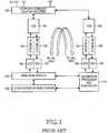
- FIG. 1is a block diagram of a conventional calibration apparatus in a smart antenna system.
- a transmission (Tx) calibration signalis transferred in the following manner. First, a calibration signal generated from a calibration processor and controller 110 under the control of other layers of the BS 109 is provided to a baseband module 108. The calibration signal is then transmitted to antennas 101 through a Radio Frequency (RF) module.
- RFRadio Frequency
- the RF moduleoversamples the calibration signal in a Digital UpConverter (DUC) 106, modulates the oversampled signal to an RF signal in a Tx module 104, and transmits the modulated signal to the antennas 101 through a Transceiver Control Board (TCB) 103 and a coupler-splitter 102. Meanwhile, the calibration signal is coupled in the coupler-splitter 102 and transferred in a calibration path. Specifically, this calibration signal returns to the calibration processor and controller 110 through a TCB 103, a reception (Rx) module 105, and a Digital DownConverter (DDC) 107 in a Tx calibration path.
- DUCDigital UpConverter
- a calibration signal generated from the calibration processor and controller 110passes through a DUC 106, a Tx module 104, and a TCB 103 in an Rx path and is coupled to signals received at the antennas 101 in a coupler-combiner 102.
- the coupled signalreturns to the calibration processor and controller 110 through a TCB 103, an Rx module 105, a DDC 107, and the baseband module 109 in an Rx calibration path.
- calibration vectorsare estimated for Tx calibration and Rx calibration by computing differences in phase and amplitude between calibration signals generated from the calibration processor and controller 110 and the calibration signals fed back from the Tx and Rx paths.
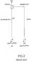
- FIG 2illustrates the principle of calibration in the conventional smart antenna system.
- a Tx or Rx calibration signal C(t)experiences variations in its phase and amplitude as it travels in a path running to antennas and in a feedback path. Given N antennas, the calibration signal C(t) is received from N paths.
- C n (t)denotes a feedback calibration signal from an n th path
- ⁇ ndenotes attenuation in the n th path.
- ⁇ N,calis a phase factor for n th path
- ⁇ feedbackis a phase factor for feedback path.
- a coupler characteristic R coupter from each pathmust be eliminated and for beamforming, the relative phases of the N antennas must be matched.
- Calibration vectorsare computed by Equation 2.
- beamforming weight vectors for antennasare W b1 , W b2 , W bn
- beamforming weight vectors calculated taking antenna paths into accountare W b1 W c1 , W b2 W c2 , W bn W cn .
- the calibrationmust be performed periodically for all carriers to use the smart antenna in a multicarrier communication system such as OFDMA.
- This calibrationrequires allocation of frequency resources to a calibration signal.
- the additional frequency resource allocation for the calibration signalleads to dissipation of frequency resources and thus there is a need for a technique of solving this problem.
- JP 2003 273634 Arefers to an array antenna device in which a calibration is performed without stopping a receiving function in the array antenna device.
- a phase deviation arithmetic circuitcarries out the calibration by introducing a calibration signal from a calibration signal generation circuit based upon selected synchronous switching operations to first and second switchers, when composing signals from respective antenna elements via phase shifters. Therefore, the other receiving system, except for a switched and selected receiving system, continues an ordinary receiving operation based upon a formed received beam pattern without being stagnated.
- US 6,208,287 B1describes a phased array antenna calibration system and a respective method thereof.
- the described self-contained calibration and failure detection in a phase array antennahas a beam-forming network.
- the beam-forming networkincludes a plurality of array ports and a plurality of beam ports or a space fed system.
- a plurality of antenna elements and a plurality of transmit/receive modulesare included. Each one of the modules is coupled between a corresponding one of the antenna elements and a corresponding one of the array ports.
- a calibration systemis provided which has an RF input port, an RF detector port, an RF detector coupled to the RF detector port, and an antenna element port.
- a switch sectionis included for sequentially coupling each of the antenna elements through the beam-forming/space-fed network and the one of the transmit/receive modules coupled thereto selectively to either the detector port during a receive calibration mode or to the RF input port during a transmit calibration mode.
- the switch sectionincludes a switch for selectively coupling a predetermined one of the antenna elements, i.e. a calibration antenna element, selectively to either the RF test input of the calibration system during the receive calibration mode through a path isolated from the beam-forming network or to the detector port during the transmit calibration mode through a path isolated from the beam-forming network.
- US 5,499,031refers to a distributed receiver system for antenna array. It describes that in an antenna array of large dimensions, such as might be used for high frequency radar, the antennas will be connected by short feeders to receivers which will consequently be distributed over a considerable distance. Calibration of such an antenna array to compensate for variations in the transfer functions of the receivers will necessitate the same test signal being fed into each element in turn to measure the receiver output, and this could be time consuming and hence reduce the time available for use of the array.
- a loopis connected at various tappings to the feeders, the respective antennas are disconnected, and sinusoidal tones are injected into the left hand and right hand ends of the loop. The outputs of the receivers are measured, and provide a measure of the transfer functions of the receivers and hence enable discrepancies between them to be corrected.
- EP 1 416 655refers to a calibration method in an OFDM system and injects calibration signals along the multiple subcarriers used in that OFDM system. Accordingly, an object of the present invention is to provide an improved calibration apparatus and method for controlling the phase and amplitude of a signal in a smart antenna multicarrier communication system.
- An aspect of the present inventionis to provide a calibration apparatus and method for transmitting a calibration signal by which to control the phase and amplitude of a signal on the remaining carriers after allocating data to carriers, thereby increasing the efficiency of frequency resource utilization for the data signal in a smart antenna multicarrier communication system.
- the above aspectis achieved by providing a calibration apparatus and method for controlling the phase and amplitude of a signal in a smart antenna multicarrier communication system.
- a schedulerallocates a data signal to a plurality of carriers as data carriers, provides the data signal to a baseband processor, and controls a calibration processor and controller to generate a calibration signal to be allocated to non-data carriers to which the data signal is not allocated.
- the calibration processor and controllergenerates the calibration signal on the non-data carriers under the control of the scheduler and calculates a calibration vector using the calibration signal and a feedback calibration signal (the calibration signal passed through a transmission path).
- the baseband processorcalibrates a beamforming weight vector for a data signal with the calibration vector and transmits the calibrated data signal in the transmission path.
- a data signalis allocated to a plurality of carriers as data carriers.
- a calibration signalis allocated to non-data carriers to which the data signal is not allocated and transmitted in a transmission path.
- a calibration vectoris calculated using the calibration signal and a feedback calibration signal received from the transmission path.
- a beamforming weight vectoris calibrated for the data signal using the calibration vector and the calibrated data signal is transmitted in the transmission path.
- a time thresholdis predetermined so that, unless a specific carrier to which the calibration signal was allocated has the calibration signal applied again within that time threshold, the calibration signal is forcibly allocated to the carrier so that the calibration signal is allocated across the total frequency band periodically.
- Periodic calibrationis needed for all carriers in application of a smart antenna to a multicarrier communication system like an Orthogonal Frequency Division Multiplexing (OFDM) or an Orthogonal Frequency Division Multiple Access (OFDMA) communication system.
- OFDMOrthogonal Frequency Division Multiplexing
- OFDMAOrthogonal Frequency Division Multiple Access
- FIG. 3illustrates allocation of carriers to a data signal in a smart-antenna communication system according to the present invention.
- shaded squaresdenote areas with data signals and blank squares denote areas without data signals, somme of which are allocated to a calibration signal.
- An example of allocating carriers to data over timeis shown herein. As different MSs are connected to a BS with passage of time, the allocation of frequency resources to data changes correspondingly, and carriers without data also change with passage of time, as well.
- FIG. 4is a block diagram of a calibration apparatus in a smart antenna system according to the present invention.
- reference numerals 401 to 410denote the same components 101 to 110 illustrated in FIG. 1 .
- Reference numerals 411 to 414denote components further provided according to the present invention, for allocating a calibration signal to carriers and estimating calibration vectors.
- a scheduler 412allocates a data signal to carriers taking into account calibration in each symbol and provides the data signal to a baseband processor 411.
- the scheduler 412also controls a calibration signal generator 413 and a calibration vector processor 414.
- the scheduler 412controls the calibration signal generator 413 to generate the calibration signal on non-data carriers and controls the calibration vector processor 414 to compute a calibration vector using a feedback calibration signal that has passed through a feedback path.
- This calibration signalis transmitted/received for Tx calibration and Rx calibration in the same manner as illustrated in FIG. 1 .
- FIG 5illustrates the configuration of the baseband processor 411 in the smart antenna system according to the present invention.
- the baseband processor 411 in the baseband module 408receives calibration vectors from the calibration vector processor 414 of the calibration processor and controller 410.
- a data mapper 504maps non-data carriers to multipliers 502.
- a calibrator 503provides the calibration vectors to multipliers 502.
- the multipliers 502multiply the carrier signals with the calibration vectors and an inverse fast Fourier transform (IFFT)/FFT processor 501 modulates the products by IFFT.
- IFFTinverse fast Fourier transform
- the IFFT/FFT 501demodulates a received data signal by FFT.
- the calibrator 503applies the calibration vectors received from the calibration vector processor 414 to the FFT signals.
- FIG. 6is a block diagram of the scheduler 412 in the smart antenna system according to the present invention.
- the scheduler 412functions to allocate a calibration signal to carriers by controlling the calibration signal generator 413.
- a carrier-set finder 601finds carriers whose timer values do not exceed a threshold (Time_threshold) as data carriers to which data can be allocated.
- a data allocater 603allocates data to the carriers found by the carrier-set finder 601.
- a timer 602updates its timer value for a corresponding data carrier to which the data allocater 603 has allocated data.
- FIG 7is a block diagram of the calibration signal generator 413 in the smart antenna system according to the present invention.
- the calibration signal generator 413includes a calibration signal allocater 701 and an IFFT processor 702.
- the calibration signal allocater 701allocates a calibration signal to non-data carriers based on carrier-data allocation information received from the scheduler 412.
- the IFFT processor 702modulates the calibration carrier signals by IFFT.
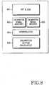
- FIG. 8is a block diagram of the calibration vector processor 414 in the smart antenna system according to the present invention.
- the calibration vector processor 414includes an FFT processor 801, a calibration signal acquirer 802, a calibration signal updater 803, an interpolator 804, and a calibration vector calculator 805.
- the FFT processor 801separates a feedback calibration signal by carriers.
- the calibration signal acquirer 802measures the phase and amplitude of the feedback calibration signals of calibration carriers according to calibration carrier position information received from the scheduler 412.
- the calibration signal updater 803updates the phase and amplitude information each time and stores it in a memory.
- the interpolator 804interpolates the stored phase and amplitude information, thereby estimating the phases and amplitudes of the calibration signal on carriers to which the calibration signal was not allocated. The interpolation is carried out in the case where a large number of MSs are connected to the BS.
- the calibration vector calculator 805calculates calibration vectors after eliminating coupler characteristics from the feedback calibration signal.
- FIG. 9is a flowchart illustrating an operation for allocating carriers to a calibration signal in the smart antenna system according to the present invention.
- a timer for each carrieris reset to 0 before the BS operates.
- a variable n indicating a carrieris set to 1 in step 901.
- the timer value of the n th carrieris compared with a timer threshold (Time_threshold). If timer value of the n th carrier is greater than the threshold, the n th carrier is excluded as unavailable as a data carrier in step 903. In this case n is updated to n+1 in step 904 and returned to step 902.
- the n th carriermay be data carriers in step 905. Because the data is not allocated to all data carriers, carriers for which the data is not allocated may exist. In step 906, it is confirmed whether data is allocated. If data is not allocated, then a calibration signal is allocated to such a non-data carrier in step 907. A symbol having the calibration signal and the data signal is then transmitted.
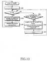
- FIG 10is a flowchart illustrating an operation for estimating a calibration vector in the smart antenna system according to the present invention.
- a variable n indicating a carrieris set to 1 in step 1001. If n th is less than N(total number of carriers), it is confirmed in step 1005 whether a calibration signal was allocated to n th carrier. If a calibration signal was allocated to the n th carrier, then the calibration signal response on the calibration carriers is received and the phase and amplitudes of the calibration carriers are stored in a memory in step 1006.
- n th carrierFor an n th carrier, if it carries the calibration signal, the memory, which has already stored the phases and amplitudes of previous calibration carriers, is updated with the phase and amplitude of the calibration signal on the n th carrier at an n th address. In step 1007, this operation is repeated for all carriers. Then the calibration signals are interpolated using the stored phases and amplitudes of the calibration carriers in step 1003. After eliminating coupler characteristics from the calibration signal, a calibration vector is computed for each carrier in step 1004.
- FIGs. 11A and 11Billustrate the values of feedback calibration signals in the smart antenna system according to the present invention.
- a calibration signalis transmitted for a predetermined time of period and fed back.
- a signalcan be calibrated across a total frequency band. Since the system knows the phase and amplitude of the transmitted calibration signal, it can compute calibration vectors by comparing the value of the transmitted calibration signal with that of the feedback calibration signal. Thus, the phase and amplitude of a signal can be calibrated using the calibration vectors. In the case where a small number of users are connected to a BS, this method is applicable.
- the calibration signalis not transmitted across the total frequency band and thus the values of feedback calibration signals are estimated by interpolation.
- This methodis available when a large number of users are connected to the BS and more data carriers are needed.
- the systemsince the system knows the phase and amplitude of the transmitted calibration signal, it can compute calibration vectors by comparing the value of the transmitted calibration signal with that of the feedback calibration signal. Thus, the phase and amplitude of a signal can be calibrated using the calibration vectors.
- a calibration signalis allocated to the remaining carriers after allocating carriers to a data signal, prior to transmission in a smart antenna multicarrier communication system.
- the efficiency of frequency resources for data transmissionis increased.
Landscapes
- Engineering & Computer Science (AREA)
- Computer Networks & Wireless Communication (AREA)
- Signal Processing (AREA)
- Radio Transmission System (AREA)
Description
- The present invention relates generally to a calibration apparatus and method for controlling the phase and amplitude of a signal in a smart antenna multicarrier communication system, and in particular, to an apparatus and method for transmitting a calibration signal on the remaining carriers after allocating data to carriers, thereby increasing the efficiency of frequency resource utilization for the data signal.
- A smart antenna system is a communication system that uses a plurality of antennas to automatically optimize a radiation pattern and/or a reception pattern according to a signal environment. From the perspective of data signal transmission, the smart antenna system transmits a signal with a desired strength in an intended direction at a minimum power level by beamforming. The use of the smart antenna enables a Base Station (BS) to direct a signal only to a desired Mobile Station (MS) through beamforming. Therefore, compared to omnidirectional signal transmission to all MSs, the smart antenna reduces power required for signal transmission and interference, as well. Since the smart antenna applies directionality to a transmission/received signal by actively locating an intended MS, interference to other MSs within the same cell can be minimized. Thus, the BS can allocate the remaining available power to other MSs and the reduced interference with other cells leads to the increase of BS channel capacity.
- A wireless internet service system based on Orthogonal Frequency Division Multiple Access (OFDMA) uses a wide frequency bandwidth and transmits a signal from a BS to one MS at a higher power level than in a conventional system. Thus, a cell radius is small. Application of the smart antenna to the wireless internet system advantageously increases BS channel capacity.
- In application of the smart antenna system to a multicarrier OFDMA system, beamforming is performed by using a beamforming weight vector for each orthogonal frequency carrier of each antenna such that each antenna beam is steered in a chosen direction. The beams must reach the antennas without any change prior to transmission over the air, but they experience distortions in their phase and amplitude due to non-linear components in the BS. Thus, calibration is needed to control the phase and amplitude of the signals. The total performance of the smart antenna technology depends on the accuracy of the calibration, that is, the accuracy of beam directionality and minimization of phase mismatch. The calibration is commonly applied to a downlink directed from a BS to an MS and an uplink directed from an MS to a BS.
FIG. 1 is a block diagram of a conventional calibration apparatus in a smart antenna system. Referring toFIG. 1 , a transmission (Tx) calibration signal is transferred in the following manner. First, a calibration signal generated from a calibration processor andcontroller 110 under the control of other layers of the BS 109 is provided to abaseband module 108. The calibration signal is then transmitted toantennas 101 through a Radio Frequency (RF) module. The RF module oversamples the calibration signal in a Digital UpConverter (DUC) 106, modulates the oversampled signal to an RF signal in aTx module 104, and transmits the modulated signal to theantennas 101 through a Transceiver Control Board (TCB) 103 and a coupler-splitter 102. Meanwhile, the calibration signal is coupled in the coupler-splitter 102 and transferred in a calibration path. Specifically, this calibration signal returns to the calibration processor andcontroller 110 through aTCB 103, a reception (Rx)module 105, and a Digital DownConverter (DDC) 107 in a Tx calibration path.- As to an Rx calibration signal, a calibration signal generated from the calibration processor and
controller 110 passes through aDUC 106, aTx module 104, and aTCB 103 in an Rx path and is coupled to signals received at theantennas 101 in a coupler-combiner 102. The coupled signal returns to the calibration processor andcontroller 110 through aTCB 103, anRx module 105, aDDC 107, and thebaseband module 109 in an Rx calibration path. - As described above, calibration vectors are estimated for Tx calibration and Rx calibration by computing differences in phase and amplitude between calibration signals generated from the calibration processor and
controller 110 and the calibration signals fed back from the Tx and Rx paths. FIG 2 illustrates the principle of calibration in the conventional smart antenna system. A Tx or Rx calibration signal C(t) experiences variations in its phase and amplitude as it travels in a path running to antennas and in a feedback path. Given N antennas, the calibration signal C(t) is received from N paths. Thus, according to Equation 1:
- For calculation of a calibration vector, a coupler characteristic Rcoupter from each path must be eliminated and for beamforming, the relative phases of the N antennas must be matched. Calibration vectors are computed by Equation 2.

- Assuming that beamforming weight vectors for antennas are Wb1, Wb2, Wbn, beamforming weight vectors calculated taking antenna paths into account are Wb1Wc1, Wb2Wc2, WbnWcn.
- The calibration must be performed periodically for all carriers to use the smart antenna in a multicarrier communication system such as OFDMA. This calibration requires allocation of frequency resources to a calibration signal. However, the additional frequency resource allocation for the calibration signal leads to dissipation of frequency resources and thus there is a need for a technique of solving this problem.
JP 2003 273634 A US 6,208,287 B1 describes a phased array antenna calibration system and a respective method thereof. The described self-contained calibration and failure detection in a phase array antenna has a beam-forming network. The beam-forming network includes a plurality of array ports and a plurality of beam ports or a space fed system. A plurality of antenna elements and a plurality of transmit/receive modules are included. Each one of the modules is coupled between a corresponding one of the antenna elements and a corresponding one of the array ports. Additionally, a calibration system is provided which has an RF input port, an RF detector port, an RF detector coupled to the RF detector port, and an antenna element port. Furthermore, a switch section is included for sequentially coupling each of the antenna elements through the beam-forming/space-fed network and the one of the transmit/receive modules coupled thereto selectively to either the detector port during a receive calibration mode or to the RF input port during a transmit calibration mode. Additionally, the switch section includes a switch for selectively coupling a predetermined one of the antenna elements, i.e. a calibration antenna element, selectively to either the RF test input of the calibration system during the receive calibration mode through a path isolated from the beam-forming network or to the detector port during the transmit calibration mode through a path isolated from the beam-forming network.US 5,499,031 refers to a distributed receiver system for antenna array. It describes that in an antenna array of large dimensions, such as might be used for high frequency radar, the antennas will be connected by short feeders to receivers which will consequently be distributed over a considerable distance. Calibration of such an antenna array to compensate for variations in the transfer functions of the receivers will necessitate the same test signal being fed into each element in turn to measure the receiver output, and this could be time consuming and hence reduce the time available for use of the array. In order to overcome this disadvantage, a loop is connected at various tappings to the feeders, the respective antennas are disconnected, and sinusoidal tones are injected into the left hand and right hand ends of the loop. The outputs of the receivers are measured, and provide a measure of the transfer functions of the receivers and hence enable discrepancies between them to be corrected.EP 1 416 655- This object is solved by the present invention and, in particular, by the subject matter of the independent claims. Preferred embodiments are subject matter of the dependent claims
- An aspect of the present invention is to provide a calibration apparatus and method for transmitting a calibration signal by which to control the phase and amplitude of a signal on the remaining carriers after allocating data to carriers, thereby increasing the efficiency of frequency resource utilization for the data signal in a smart antenna multicarrier communication system.
- The above aspect is achieved by providing a calibration apparatus and method for controlling the phase and amplitude of a signal in a smart antenna multicarrier communication system.
- According to one aspect of the present invention, in a smart antenna communication system, a scheduler allocates a data signal to a plurality of carriers as data carriers, provides the data signal to a baseband processor, and controls a calibration processor and controller to generate a calibration signal to be allocated to non-data carriers to which the data signal is not allocated. The calibration processor and controller generates the calibration signal on the non-data carriers under the control of the scheduler and calculates a calibration vector using the calibration signal and a feedback calibration signal (the calibration signal passed through a transmission path). The baseband processor calibrates a beamforming weight vector for a data signal with the calibration vector and transmits the calibrated data signal in the transmission path.
- According to another aspect of the present invention, in a signal calibration method in a smart antenna communication system, a data signal is allocated to a plurality of carriers as data carriers. A calibration signal is allocated to non-data carriers to which the data signal is not allocated and transmitted in a transmission path. A calibration vector is calculated using the calibration signal and a feedback calibration signal received from the transmission path. A beamforming weight vector is calibrated for the data signal using the calibration vector and the calibrated data signal is transmitted in the transmission path.
- In these two systems, a time threshold is predetermined so that, unless a specific carrier to which the calibration signal was allocated has the calibration signal applied again within that time threshold, the calibration signal is forcibly allocated to the carrier so that the calibration signal is allocated across the total frequency band periodically. The above and other objects, features and advantages of the present invention will become more apparent from the following detailed description when taken in conjunction with the accompanying drawings in which:
FIG 1 is a block diagram of a conventional signal calibration apparatus in a smart-antenna communication system;FIG. 2 illustrates the principle of signal calibration in the smart-antenna communication system;FIG. 3 illustrates allocation of carriers to a data signal in a smart-antenna communication system according to the present invention;FIG. 4 is a block diagram of a calibration apparatus in a smart antenna system according to the present invention;FIG. 5 illustrates the configuration of a baseband processor in the smart antenna system according to the present invention;FIG. 6 is a block diagram of a scheduler in the smart antenna system according to the present invention;FIG 7 is a block diagram of a calibration signal generator in the smart antenna system according to the present invention;FIG. 8 is a block diagram of a calibration vector processor in the smart antenna system according to the present invention;FIG. 9 is a flowchart illustrating an operation for allocating carriers to a calibration signal in the smart antenna system according to the present invention;FIG. 10 is a flowchart illustrating an operation for estimating a calibration vector in the smart antenna system according to the present invention; andFIGs. 11A and11B illustrate the values of feedback calibration signals in the smart antenna system according to the present invention.- A preferred embodiment of the present invention will be described herein below with reference to the accompanying drawings. In the following description, well-known functions or constructions are not described in detail since they would obscure the invention in unnecessary detail.
- Periodic calibration is needed for all carriers in application of a smart antenna to a multicarrier communication system like an Orthogonal Frequency Division Multiplexing (OFDM) or an Orthogonal Frequency Division Multiple Access (OFDMA) communication system.
- A description will first be made of carrier allocation to data in such a communication system.
FIG. 3 illustrates allocation of carriers to a data signal in a smart-antenna communication system according to the present invention. Referring toFIG. 3 , shaded squares denote areas with data signals and blank squares denote areas without data signals, somme of which are allocated to a calibration signal. An example of allocating carriers to data over time is shown herein. As different MSs are connected to a BS with passage of time, the allocation of frequency resources to data changes correspondingly, and carriers without data also change with passage of time, as well.- It is possible to calibrate carriers without data by mapping a calibration signal to the non-data carriers. Continuous calibration of the non-data carriers for a predetermined period of time leads to calibration across a total frequency band. For efficient calibration of the total frequency band, therefore, the non-data carriers must be uniformly distributed across the total frequency band. In addition, unless a specific carrier to which the calibration signal was allocated has the calibration signal applied again a predetermined time later (Time_threshold), the calibration signal must be forcibly allocated to the carrier so that the calibration signal is allocated across the total frequency band periodically.
FIG. 4 is a block diagram of a calibration apparatus in a smart antenna system according to the present invention. Referring toFIG. 4 ,reference numerals 401 to 410 denote thesame components 101 to 110 illustrated inFIG. 1 . Reference numerals 411 to 414 denote components further provided according to the present invention, for allocating a calibration signal to carriers and estimating calibration vectors. Ascheduler 412 allocates a data signal to carriers taking into account calibration in each symbol and provides the data signal to a baseband processor 411. Thescheduler 412 also controls acalibration signal generator 413 and acalibration vector processor 414. Specifically, thescheduler 412 controls thecalibration signal generator 413 to generate the calibration signal on non-data carriers and controls thecalibration vector processor 414 to compute a calibration vector using a feedback calibration signal that has passed through a feedback path. This calibration signal is transmitted/received for Tx calibration and Rx calibration in the same manner as illustrated inFIG. 1 .FIG 5 illustrates the configuration of the baseband processor 411 in the smart antenna system according to the present invention. Referring toFIG. 5 , the baseband processor 411 in thebaseband module 408 receives calibration vectors from thecalibration vector processor 414 of the calibration processor andcontroller 410. In a Tx path from the BS to an MS, adata mapper 504 maps non-data carriers to multipliers 502. Acalibrator 503 provides the calibration vectors to multipliers 502. Themultipliers 502 multiply the carrier signals with the calibration vectors and an inverse fast Fourier transform (IFFT)/FFT processor 501 modulates the products by IFFT.- In an Rx path from the MS to the BS, the above operation for the Tx path is reversed. The IFFT/
FFT 501 demodulates a received data signal by FFT. Thecalibrator 503 applies the calibration vectors received from thecalibration vector processor 414 to the FFT signals. FIG. 6 is a block diagram of thescheduler 412 in the smart antenna system according to the present invention. Referring toFIG. 6 , thescheduler 412 functions to allocate a calibration signal to carriers by controlling thecalibration signal generator 413. A carrier-setfinder 601 finds carriers whose timer values do not exceed a threshold (Time_threshold) as data carriers to which data can be allocated. Adata allocater 603 allocates data to the carriers found by the carrier-setfinder 601. Atimer 602 updates its timer value for a corresponding data carrier to which thedata allocater 603 has allocated data.FIG 7 is a block diagram of thecalibration signal generator 413 in the smart antenna system according to the present invention. Referring toFIG 7 , thecalibration signal generator 413 includes acalibration signal allocater 701 and anIFFT processor 702. Thecalibration signal allocater 701 allocates a calibration signal to non-data carriers based on carrier-data allocation information received from thescheduler 412. TheIFFT processor 702 modulates the calibration carrier signals by IFFT.FIG. 8 is a block diagram of thecalibration vector processor 414 in the smart antenna system according to the present invention. Referring toFIG 8 , thecalibration vector processor 414 includes anFFT processor 801, acalibration signal acquirer 802, acalibration signal updater 803, aninterpolator 804, and acalibration vector calculator 805. TheFFT processor 801 separates a feedback calibration signal by carriers. Thecalibration signal acquirer 802 measures the phase and amplitude of the feedback calibration signals of calibration carriers according to calibration carrier position information received from thescheduler 412. Thecalibration signal updater 803 updates the phase and amplitude information each time and stores it in a memory. Theinterpolator 804 interpolates the stored phase and amplitude information, thereby estimating the phases and amplitudes of the calibration signal on carriers to which the calibration signal was not allocated. The interpolation is carried out in the case where a large number of MSs are connected to the BS. Thecalibration vector calculator 805 calculates calibration vectors after eliminating coupler characteristics from the feedback calibration signal.FIG. 9 is a flowchart illustrating an operation for allocating carriers to a calibration signal in the smart antenna system according to the present invention. Referring toFIG. 9 , a timer for each carrier is reset to 0 before the BS operates. A variable n indicating a carrier is set to 1 instep 901. Instep 902, the timer value of the nth carrier is compared with a timer threshold (Time_threshold). If timer value of the nth carrier is greater than the threshold, the nth carrier is excluded as unavailable as a data carrier instep 903. In this case n is updated to n+1 instep 904 and returned to step 902. On the other hand, if timer value of the nth carrier is not greater than the threshold, the nth carrier may be data carriers instep 905. Because the data is not allocated to all data carriers, carriers for which the data is not allocated may exist. Instep 906, it is confirmed whether data is allocated. If data is not allocated, then a calibration signal is allocated to such a non-data carrier instep 907. A symbol having the calibration signal and the data signal is then transmitted.FIG 10 is a flowchart illustrating an operation for estimating a calibration vector in the smart antenna system according to the present invention. Referring toFIG. 10 , a variable n indicating a carrier is set to 1 instep 1001. If nth is less than N(total number of carriers), it is confirmed instep 1005 whether a calibration signal was allocated to nth carrier. If a calibration signal was allocated to the nth carrier, then the calibration signal response on the calibration carriers is received and the phase and amplitudes of the calibration carriers are stored in a memory in step 1006. For an nth carrier, if it carries the calibration signal, the memory, which has already stored the phases and amplitudes of previous calibration carriers, is updated with the phase and amplitude of the calibration signal on the nth carrier at an nth address. Instep 1007, this operation is repeated for all carriers. Then the calibration signals are interpolated using the stored phases and amplitudes of the calibration carriers instep 1003. After eliminating coupler characteristics from the calibration signal, a calibration vector is computed for each carrier instep 1004.FIGs. 11A and11B illustrate the values of feedback calibration signals in the smart antenna system according to the present invention. In the illustrated case ofFIG. 11A , a calibration signal is transmitted for a predetermined time of period and fed back. By storing the feedback calibration signals received for the period of time, a signal can be calibrated across a total frequency band. Since the system knows the phase and amplitude of the transmitted calibration signal, it can compute calibration vectors by comparing the value of the transmitted calibration signal with that of the feedback calibration signal. Thus, the phase and amplitude of a signal can be calibrated using the calibration vectors. In the case where a small number of users are connected to a BS, this method is applicable.- In the illustrated case of
FIG 11B , the calibration signal is not transmitted across the total frequency band and thus the values of feedback calibration signals are estimated by interpolation. This method is available when a large number of users are connected to the BS and more data carriers are needed. Also, since the system knows the phase and amplitude of the transmitted calibration signal, it can compute calibration vectors by comparing the value of the transmitted calibration signal with that of the feedback calibration signal. Thus, the phase and amplitude of a signal can be calibrated using the calibration vectors. - In accordance with the present invention as described above, a calibration signal is allocated to the remaining carriers after allocating carriers to a data signal, prior to transmission in a smart antenna multicarrier communication system. Thus, the efficiency of frequency resources for data transmission is increased.


Claims (20)
- A smart antenna communication system comprising:a scheduler (412) for allocating a data signal to a plurality of carriers as data carriers, providing the data signal to a baseband processor (411), and controlling a calibration processor and controller (410) to generate a calibration signal to be allocated to non-data carriers to which the data signal is not allocated;the calibration processor and controller generating the calibration signal on the non-data carriers under the control of the scheduler, and calculating a calibration vector using the calibration signal and a feedback calibration signal, being the calibration signal passed through a transmission path; and a baseband processor (411) for calibrating a beamforming weight vector for a data signal with the calibration vector and transmitting the calibrated data signal in the transmission path;characterized in that a time threshold is predetermined so that, unless a specific carrier to which the calibration signal was allocated has the calibration signal applied again within that time threshold, the calibration signal is forcibly allocated to the carrier so that the calibration signal is allocated across the total frequency band periodically.
- The smart antenna communication system of claim 1, wherein the calibration processor and controller further comprises:a calibration signal generator (413) for generating the calibration signal on the non-data carriers under the control of the scheduler; anda calibration vector processor (414) for calculating the calibration vector using the calibration signal and the feedback calibration signal.
- The smart antenna communication system of claim 2, wherein the calibration signal generator comprises:a calibration signal allocater (701) for allocating the calibration signal to the non-data carriers according to carrier-data allocation information received from the scheduler; anda first inverse fast Fourier transform, IFFT, processor (702) for modulating the calibration signal received from the calibration signal allocater by IFFT.
- The smart antenna communication system of claim 2 or 3, wherein the calibration vector processor comprises:a fast Fourier transform, FFT, processor for separating the feedback calibration signal by carriers;a calibration signal acquirer (802) for measuring the phases and amplitudes of the calibration signal on the non-data carriers to which the calibration signal is allocated, based on calibration carrier position information received from the scheduler;a calibration signal updater (803) for updating a memory with the phase and amplitude measurements; anda calibration vector calculator (805) for eliminating coupler characteristics from the phase and amplitude measurements stored in the memory and calculating a calibration vector using the coupler characteristics from phase and amplitude measurements.
- The smart antenna communication system of claim 4, further comprising an interpolator (804) for estimating the phases and amplitudes of the calibration signal on carriers to which the calibration signal is not allocated by interpolating the phase and amplitude measurements stored in the memory, and storing the estimated phased and amplitudes of the calibration signal in the memory.
- The smart antenna communication system of claim 1, wherein the scheduler comprises:a carrier-set finder (601) for finding carriers having timer values not exceeding a threshold as data carriers;a data allocater (603) for allocating the data signal to the data carriers; anda timer (602) for updating timer values for the data carriers.
- The smart antenna communication system of claim 1, wherein the baseband processor comprises:a data mapper (504) for receiving the data signal allocated to the data carriers by the scheduler;a calibrator (503) for applying the calibration vector received from the calibration vector processor to the data signal; anda second IFFT processor (501) for modulating the data signal received from the calibrator by IFFT.
- The smart antenna communication system of claim 1, wherein the smart antenna communication system is an Orthogonal Frequency Division Multiplexing, in the following referred to as OFDM, or an Orthogonal Frequency Division Multiple Access, in the following referred to as OFDMA, communication system.
- A smart antenna communication system comprising:a scheduler (412) for controlling a calibration signal generator to generate a calibration signal to be allocated to non-data carriers other than data carriers on which a data signal is received from a mobile station;a calibration processor and controller (410) for allocating the calibration signal on the non-data carriers under the control of the scheduler and calculating a calibration vector using the calibration signal and a feedback calibration signal being the calibration signal passed through a reception path; anda baseband processor (411) for calibrating a beamforming weight vector for a data signal with the calibration vector and transmitting the calibrated data signal in the reception path;characterized in that a time threshold is predetermined so that, unless a specific carrier to which the calibration signal was allocated has the calibration signal applied again within that time threshold, the calibration signal is forcibly allocated to the carrier so that the calibration signal is allocated across the total frequency band periodically.
- The smart antenna communication system of claim 9, wherein the calibration processor and controller comprises:the calibration signal generator (413) for generating the calibration signal on the non-data carriers under the control of the scheduler; anda calibration vector processor (414) for calculating the calibration vector using the calibration signal and the feedback calibration signal.
- The smart antenna communication system of claim 10, wherein the smart antenna communication system is an OFDM (Orthogonal Frequency Division Multiplexing) or an OFDMA (Orthogonal Frequency Division Multiple Access) communication system.
- A signal calibration method in a smart antenna communication system, comprising the steps of:allocating a data signal to a plurality of carriers as data carriers;allocating a calibration signal to non-data carriers to which the data signal is not allocated and transmitting the calibration signal in a transmission path;calculating a calibration vector using the calibration signal and a feedback calibration signal received from the transmission path; andcalibrating a beamforming weight vector for the data signal using the calibration vector and transmitting the calibrated data signal in the transmission path;characterized in that a time threshold is predetermined so that, unless a specific carrier to which the calibration signal was allocated has the calibration signal applied again within that time threshold, the calibration signal is forcibly allocated to the carrier so that the calibration signal is allocated across the total frequency band periodically.
- The signal calibration method of claim 12, wherein the calibration signal allocation and transmission step comprises:allocating the calibration signal to the non-data carriers; andmodulating the allocated calibration signal.
- The signal calibration method of claim 12, wherein the calibration and transmission step comprises:receiving the data signal on each of the data carriers;applying the calibration vector to the data signal; andmodulating the data signal to which the calibration vector is applied.
- The signal calibration method of claim 12 or 13, wherein the calculation step comprises the steps of:separating the feedback signal by carriers;measuring the phases and amplitudes of the calibration signal on the non-data carriers to which the calibration signal is allocated based on calibration carrier position information;updating a memory with the phase and amplitude measurements; andeliminating coupler characteristics from the phase and amplitude measurements stored in the memory and calculating a calibration vector using the coupler characteristics-free from phase and amplitude measurements.
- The signal calibration method of claim 15, wherein the memory updating step comprises estimating the phases and amplitudes of the calibration signal on carriers to which the calibration signal is not allocated by interpolating the phase and amplitude measurements stored in the memory, and storing the estimated phased and amplitudes of the calibration signal in the memory.
- The signal calibration method of claim 12, wherein the step of allocating a calibration signal to non-data carriers further comprises the steps of:comparing a timer value of the nth carrier with a timer threshold (Time_threshold);excluding the nth carrier as unavailable as a data carrier if timer value of the nth carrier is greater than the threshold;allocating data on the nth carrier if timer value of the nth carrier is not greater than the timer threshold;allocating a calibration signal on the nth carrier if data is not allocated in the step of allocating data.
- The signal calibration method of claim 12, wherein the step of calculating a calibration vector further comprises the steps of:receiving a feedback calibration signal on a carrier to which a calibration signal is allocated;updating a memory having the values of the feedback calibration signal received on previous carriers with the value of the feedback calibration signal;repeating the reception step and the updating step for all carriers of a symbol; andcalculating a calibration vector for each of the carriers using the values of the feedback calibration signal stored in the memory.
- The signal calibration method of claim 18, further comprising eliminating a coupler characteristic from the values of the feedback calibration signal stored in the memory and calculating the calibration vector for the each carrier.
- The signal calibration method of claim 18, further comprising calculating the calibration vector for the each carrier by estimating the values of the feedback calibration signal on carriers to which the calibration signal is not allocated.
Applications Claiming Priority (1)
| Application Number | Priority Date | Filing Date | Title |
|---|---|---|---|
| KR1020040100181AKR100633047B1 (en) | 2004-12-02 | 2004-12-02 | Smart Antenna Communication System Implementing Signal Correction Apparatus and Method |
Publications (2)
| Publication Number | Publication Date |
|---|---|
| EP1670094A1 EP1670094A1 (en) | 2006-06-14 |
| EP1670094B1true EP1670094B1 (en) | 2017-05-31 |
Family
ID=35841700
Family Applications (1)
| Application Number | Title | Priority Date | Filing Date |
|---|---|---|---|
| EP05026272.4ACeasedEP1670094B1 (en) | 2004-12-02 | 2005-12-01 | Smart antenna communication system for signal calibration |
Country Status (5)
| Country | Link |
|---|---|
| US (1) | US7801564B2 (en) |
| EP (1) | EP1670094B1 (en) |
| JP (1) | JP4455483B2 (en) |
| KR (1) | KR100633047B1 (en) |
| CN (1) | CN1783748B (en) |
Families Citing this family (27)
| Publication number | Priority date | Publication date | Assignee | Title |
|---|---|---|---|---|
| US7652577B1 (en) | 2006-02-04 | 2010-01-26 | Checkpoint Systems, Inc. | Systems and methods of beamforming in radio frequency identification applications |
| US7873326B2 (en) | 2006-07-11 | 2011-01-18 | Mojix, Inc. | RFID beam forming system |
| KR101009781B1 (en)* | 2006-07-11 | 2011-01-19 | 삼성전자주식회사 | Calibration device and method in communication system |
| PL2067278T3 (en)* | 2006-08-22 | 2017-07-31 | Koninklijke Philips N.V. | Method for transmitting data in a mobile system and radio stations therefor |
| US20080207258A1 (en)* | 2007-02-26 | 2008-08-28 | Broadcom Corporation, A California Corporation | Multimode transmitter with digital up conversion and methods for use therewith |
| US20090093222A1 (en)* | 2007-10-03 | 2009-04-09 | Qualcomm Incorporated | Calibration and beamforming in a wireless communication system |
| CN101414875B (en)* | 2007-10-15 | 2013-06-26 | 中国移动通信集团上海有限公司 | Method, device and system for covering tunnel in time division duplex system |
| EP2235921A2 (en)* | 2008-01-22 | 2010-10-06 | Provigent Ltd. | Beamforming in mimo communication systems |
| KR101452999B1 (en)* | 2008-01-25 | 2014-10-21 | 삼성전자주식회사 | Apparatus and method for calibration in multi-antenna system |
| US8217760B2 (en)* | 2008-03-20 | 2012-07-10 | Checkpoint Systems, Inc. | Applique nodes for performance and functionality enhancement in radio frequency identification systems |
| EP3232414A1 (en) | 2008-04-14 | 2017-10-18 | Mojix, Inc. | Radio frequency identification tag location estimation and tracking system |
| CN101304276B (en)* | 2008-06-30 | 2012-07-04 | 华为技术有限公司 | Method and system for transmitting channel correction |
| JP2010021784A (en)* | 2008-07-10 | 2010-01-28 | Sony Corp | Communication apparatus, and communication calibration method |
| US8786440B2 (en)* | 2009-10-02 | 2014-07-22 | Checkpoint Systems, Inc. | Calibration of beamforming nodes in a configurable monitoring device system |
| CN101951618A (en)* | 2010-08-31 | 2011-01-19 | 芯通科技(成都)有限公司 | RRU (Remote Radio Unit) automatic calibration and test system |
| CN102812594B (en)* | 2010-09-08 | 2015-08-19 | 华为技术有限公司 | A kind of channel calibration method, Apparatus and system |
| JP5599353B2 (en)* | 2011-03-30 | 2014-10-01 | パナソニック株式会社 | Transceiver |
| US9178737B2 (en)* | 2012-11-20 | 2015-11-03 | Intel Deutschland Gmbh | Method for generating an OFDM data signal |
| US9755707B2 (en) | 2013-01-30 | 2017-09-05 | Telefonaktiebolaget Lm Ericsson (Publ) | Method and apparatus for calibrating multiple antennas |
| US9596676B2 (en)* | 2013-02-13 | 2017-03-14 | Qualcomm Incorporated | Calibration of a downlink transmit path of a base station |
| WO2014179818A1 (en)* | 2013-05-03 | 2014-11-06 | CommSense LLC | Antenna environment sensing device |
| US9883337B2 (en) | 2015-04-24 | 2018-01-30 | Mijix, Inc. | Location based services for RFID and sensor networks |
| JP2018019374A (en) | 2016-07-29 | 2018-02-01 | 富士通株式会社 | Base station and antenna calibration method |
| US10326538B2 (en)* | 2017-04-05 | 2019-06-18 | Cisco Technology, Inc. | Remote radio head reciprocity calibration |
| JP2019114961A (en)* | 2017-12-25 | 2019-07-11 | 富士通株式会社 | Radio communication equipment, and antenna calibration method |
| JP6887569B2 (en)* | 2018-07-24 | 2021-06-16 | 三菱電機株式会社 | Array antenna calibration device and calibration method, array antenna, and program |
| KR102195541B1 (en)* | 2018-08-10 | 2020-12-28 | 주식회사 다빈시스템스 | Method and Apparatus for Calibrating a Multi-Channel RF System |
Family Cites Families (19)
| Publication number | Priority date | Publication date | Assignee | Title |
|---|---|---|---|---|
| GB2285537B (en)* | 1989-09-28 | 1995-11-08 | Marconi Co Ltd | Calibration of distributed receiver system for antenna array |
| GB2313523B (en) | 1996-05-23 | 2000-06-07 | Motorola Ltd | Self-calibration apparatus and method for communication device |
| JP3369466B2 (en) | 1997-03-18 | 2003-01-20 | 松下電器産業株式会社 | Calibration device for array antenna wireless receiver |
| US6208287B1 (en)* | 1998-03-16 | 2001-03-27 | Raytheoncompany | Phased array antenna calibration system and method |
| ID27970A (en)* | 1998-08-05 | 2001-05-03 | Sanyo Electric Co | RADAS RADIO AND CALIBRATION METHODS FOR THAT |
| US6184829B1 (en)* | 1999-01-08 | 2001-02-06 | Trueposition, Inc. | Calibration for wireless location system |
| KR100399692B1 (en) | 1999-03-30 | 2003-09-29 | 산요덴키가부시키가이샤 | Radio device and method of calibration of antenna directivity |
| JP2003218621A (en) | 2002-01-21 | 2003-07-31 | Nec Corp | Apparatus and method for calibrating array antenna |
| JP3769513B2 (en)* | 2002-03-19 | 2006-04-26 | 株式会社東芝 | Array antenna device |
| JP4010225B2 (en) | 2002-10-30 | 2007-11-21 | 日本電気株式会社 | Array antenna transceiver |
| KR100608736B1 (en)* | 2003-04-29 | 2006-08-04 | 엘지전자 주식회사 | Reference signal generator of smart antenna system |
| JP4388303B2 (en) | 2003-05-16 | 2009-12-24 | 日本無線株式会社 | Array antenna communication device |
| ATE487291T1 (en)* | 2003-08-27 | 2010-11-15 | Wavion Ltd | WIFI CAPACITY EXPANSION BY USING SDM |
| KR100675489B1 (en)* | 2004-11-23 | 2007-01-29 | 삼성전자주식회사 | Multi Antenna Communication System Implementing Signal Correction Apparatus and Method |
| US7362266B2 (en)* | 2004-12-07 | 2008-04-22 | Lockheed Martin Corporation | Mutual coupling method for calibrating a phased array |
| US7408507B1 (en)* | 2005-03-15 | 2008-08-05 | The United States Of America As Represented By The Secretary Of The Navy | Antenna calibration method and system |
| US8498669B2 (en)* | 2005-06-16 | 2013-07-30 | Qualcomm Incorporated | Antenna array calibration for wireless communication systems |
| US9118111B2 (en)* | 2005-11-02 | 2015-08-25 | Qualcomm Incorporated | Antenna array calibration for wireless communication systems |
| US8280430B2 (en)* | 2005-11-02 | 2012-10-02 | Qualcomm Incorporated | Antenna array calibration for multi-input multi-output wireless communication systems |
- 2004
- 2004-12-02KRKR1020040100181Apatent/KR100633047B1/ennot_activeExpired - Fee Related
- 2005
- 2005-12-01EPEP05026272.4Apatent/EP1670094B1/ennot_activeCeased
- 2005-12-02USUS11/293,564patent/US7801564B2/ennot_activeExpired - Fee Related
- 2005-12-02CNCN2005101310133Apatent/CN1783748B/ennot_activeExpired - Fee Related
- 2005-12-02JPJP2005349969Apatent/JP4455483B2/ennot_activeExpired - Fee Related
Also Published As
| Publication number | Publication date |
|---|---|
| CN1783748A (en) | 2006-06-07 |
| JP4455483B2 (en) | 2010-04-21 |
| KR20060061443A (en) | 2006-06-08 |
| JP2006166452A (en) | 2006-06-22 |
| US7801564B2 (en) | 2010-09-21 |
| CN1783748B (en) | 2010-05-12 |
| KR100633047B1 (en) | 2006-10-11 |
| EP1670094A1 (en) | 2006-06-14 |
| US20060135211A1 (en) | 2006-06-22 |
Similar Documents
| Publication | Publication Date | Title |
|---|---|---|
| EP1670094B1 (en) | Smart antenna communication system for signal calibration | |
| EP1438768B1 (en) | Frequency dependent calibration of a wideband radio system using narrowband channels | |
| EP1433271B1 (en) | Calibration of a radio communications system | |
| KR100656979B1 (en) | A method for calibrating smart antenna array systems in real time | |
| US9685702B2 (en) | Beamforming method, apparatus for polarized antenna array and radio communication device and system thereof | |
| US7389193B2 (en) | Apparatus and method for calibrating transmission paths in a multicarrier communication system using multiple antennas | |
| US8208963B2 (en) | Communication method and system | |
| US6400318B1 (en) | Adaptive array antenna | |
| US6690952B2 (en) | Adaptive array antenna transceiver apparatus | |
| US6496140B1 (en) | Method for calibrating a smart-antenna array radio transceiver unit and calibrating system | |
| EP1708385A2 (en) | Apparatus for calibrating the phases of an antenna array | |
| US20130230005A1 (en) | Method and System for Uplink Beamforming Calibration in a Multi-Antenna Wireless Communication System | |
| EP2533360B1 (en) | Method and device for antenna calibration | |
| KR20030089215A (en) | Apparatus and method for control of forward-link beamforming in mobile communication system | |
| US8886254B2 (en) | Radio base station and antenna weight setting method | |
| EP3427398B1 (en) | Method and apparatus for channel sounding for a mu-mimo wireless communication network | |
| US8219035B2 (en) | Enhanced calibration for multiple signal processing paths in a wireless network | |
| US20070183545A1 (en) | Wireless communication apparatus | |
| EP1143559B1 (en) | Adaptive array apparatus for correcting phase for forming directional pattern and correction method | |
| EP1093186B1 (en) | Radio transmitter and transmission directivity adjusting method | |
| WO2017153732A1 (en) | Method and apparatus for channel sounding for a mu-mimo wireless communication network | |
| KR20070066430A (en) | Transmission and reception path correction device of smart antenna system | |
| AU2002362566A1 (en) | Frequency dependent calibration of a wideband radio system using narrowband channels | |
| AU2002362567A1 (en) | Calibration of a radio communications system |
Legal Events
| Date | Code | Title | Description |
|---|---|---|---|
| PUAI | Public reference made under article 153(3) epc to a published international application that has entered the european phase | Free format text:ORIGINAL CODE: 0009012 | |
| AK | Designated contracting states | Kind code of ref document:A1 Designated state(s):AT BE BG CH CY CZ DE DK EE ES FI FR GB GR HU IE IS IT LI LT LU LV MC NL PL PT RO SE SI SK TR | |
| AX | Request for extension of the european patent | Extension state:AL BA HR MK YU | |
| 17P | Request for examination filed | Effective date:20060523 | |
| 17Q | First examination report despatched | Effective date:20060721 | |
| AKX | Designation fees paid | Designated state(s):DE FR GB IT SE | |
| RAP1 | Party data changed (applicant data changed or rights of an application transferred) | Owner name:SAMSUNG ELECTRONICS CO., LTD. | |
| GRAP | Despatch of communication of intention to grant a patent | Free format text:ORIGINAL CODE: EPIDOSNIGR1 | |
| INTG | Intention to grant announced | Effective date:20161209 | |
| RIN1 | Information on inventor provided before grant (corrected) | Inventor name:YANG, JANG-HOON Inventor name:CHAE, HEON-KI Inventor name:KWON, YOUNG-HOON | |
| GRAS | Grant fee paid | Free format text:ORIGINAL CODE: EPIDOSNIGR3 | |
| GRAA | (expected) grant | Free format text:ORIGINAL CODE: 0009210 | |
| AK | Designated contracting states | Kind code of ref document:B1 Designated state(s):DE FR GB IT SE | |
| REG | Reference to a national code | Ref country code:GB Ref legal event code:FG4D | |
| REG | Reference to a national code | Ref country code:DE Ref legal event code:R096 Ref document number:602005052026 Country of ref document:DE | |
| REG | Reference to a national code | Ref country code:FR Ref legal event code:PLFP Year of fee payment:13 | |
| PG25 | Lapsed in a contracting state [announced via postgrant information from national office to epo] | Ref country code:SE Free format text:LAPSE BECAUSE OF FAILURE TO SUBMIT A TRANSLATION OF THE DESCRIPTION OR TO PAY THE FEE WITHIN THE PRESCRIBED TIME-LIMIT Effective date:20170531 | |
| PG25 | Lapsed in a contracting state [announced via postgrant information from national office to epo] | Ref country code:IT Free format text:LAPSE BECAUSE OF FAILURE TO SUBMIT A TRANSLATION OF THE DESCRIPTION OR TO PAY THE FEE WITHIN THE PRESCRIBED TIME-LIMIT Effective date:20170531 | |
| REG | Reference to a national code | Ref country code:DE Ref legal event code:R097 Ref document number:602005052026 Country of ref document:DE | |
| PLBE | No opposition filed within time limit | Free format text:ORIGINAL CODE: 0009261 | |
| STAA | Information on the status of an ep patent application or granted ep patent | Free format text:STATUS: NO OPPOSITION FILED WITHIN TIME LIMIT | |
| 26N | No opposition filed | Effective date:20180301 | |
| GBPC | Gb: european patent ceased through non-payment of renewal fee | Effective date:20171201 | |
| PG25 | Lapsed in a contracting state [announced via postgrant information from national office to epo] | Ref country code:GB Free format text:LAPSE BECAUSE OF NON-PAYMENT OF DUE FEES Effective date:20171201 | |
| PGFP | Annual fee paid to national office [announced via postgrant information from national office to epo] | Ref country code:DE Payment date:20181205 Year of fee payment:14 | |
| PGFP | Annual fee paid to national office [announced via postgrant information from national office to epo] | Ref country code:FR Payment date:20181122 Year of fee payment:14 | |
| REG | Reference to a national code | Ref country code:DE Ref legal event code:R119 Ref document number:602005052026 Country of ref document:DE | |
| PG25 | Lapsed in a contracting state [announced via postgrant information from national office to epo] | Ref country code:DE Free format text:LAPSE BECAUSE OF NON-PAYMENT OF DUE FEES Effective date:20200701 Ref country code:FR Free format text:LAPSE BECAUSE OF NON-PAYMENT OF DUE FEES Effective date:20191231 |