EP1662839B1 - Loudspeaker - Google Patents
LoudspeakerDownload PDFInfo
- Publication number
- EP1662839B1 EP1662839B1EP06002707AEP06002707AEP1662839B1EP 1662839 B1EP1662839 B1EP 1662839B1EP 06002707 AEP06002707 AEP 06002707AEP 06002707 AEP06002707 AEP 06002707AEP 1662839 B1EP1662839 B1EP 1662839B1
- Authority
- EP
- European Patent Office
- Prior art keywords
- diaphragm
- voice coil
- loudspeaker
- groove
- loudspeaker according
- Prior art date
- Legal status (The legal status is an assumption and is not a legal conclusion. Google has not performed a legal analysis and makes no representation as to the accuracy of the status listed.)
- Expired - Lifetime
Links
Images


Classifications
- H—ELECTRICITY
- H04—ELECTRIC COMMUNICATION TECHNIQUE
- H04R—LOUDSPEAKERS, MICROPHONES, GRAMOPHONE PICK-UPS OR LIKE ACOUSTIC ELECTROMECHANICAL TRANSDUCERS; DEAF-AID SETS; PUBLIC ADDRESS SYSTEMS
- H04R9/00—Transducers of moving-coil, moving-strip, or moving-wire type
- H04R9/02—Details
- H—ELECTRICITY
- H04—ELECTRIC COMMUNICATION TECHNIQUE
- H04R—LOUDSPEAKERS, MICROPHONES, GRAMOPHONE PICK-UPS OR LIKE ACOUSTIC ELECTROMECHANICAL TRANSDUCERS; DEAF-AID SETS; PUBLIC ADDRESS SYSTEMS
- H04R9/00—Transducers of moving-coil, moving-strip, or moving-wire type
- H04R9/02—Details
- H04R9/04—Construction, mounting, or centering of coil
- H—ELECTRICITY
- H04—ELECTRIC COMMUNICATION TECHNIQUE
- H04R—LOUDSPEAKERS, MICROPHONES, GRAMOPHONE PICK-UPS OR LIKE ACOUSTIC ELECTROMECHANICAL TRANSDUCERS; DEAF-AID SETS; PUBLIC ADDRESS SYSTEMS
- H04R1/00—Details of transducers, loudspeakers or microphones
- H—ELECTRICITY
- H04—ELECTRIC COMMUNICATION TECHNIQUE
- H04R—LOUDSPEAKERS, MICROPHONES, GRAMOPHONE PICK-UPS OR LIKE ACOUSTIC ELECTROMECHANICAL TRANSDUCERS; DEAF-AID SETS; PUBLIC ADDRESS SYSTEMS
- H04R7/00—Diaphragms for electromechanical transducers; Cones
- H04R7/02—Diaphragms for electromechanical transducers; Cones characterised by the construction
- H04R7/04—Plane diaphragms
- H—ELECTRICITY
- H04—ELECTRIC COMMUNICATION TECHNIQUE
- H04R—LOUDSPEAKERS, MICROPHONES, GRAMOPHONE PICK-UPS OR LIKE ACOUSTIC ELECTROMECHANICAL TRANSDUCERS; DEAF-AID SETS; PUBLIC ADDRESS SYSTEMS
- H04R9/00—Transducers of moving-coil, moving-strip, or moving-wire type
- H04R9/02—Details
- H04R9/04—Construction, mounting, or centering of coil
- H04R9/045—Mounting
- H—ELECTRICITY
- H04—ELECTRIC COMMUNICATION TECHNIQUE
- H04R—LOUDSPEAKERS, MICROPHONES, GRAMOPHONE PICK-UPS OR LIKE ACOUSTIC ELECTROMECHANICAL TRANSDUCERS; DEAF-AID SETS; PUBLIC ADDRESS SYSTEMS
- H04R9/00—Transducers of moving-coil, moving-strip, or moving-wire type
- H04R9/06—Loudspeakers
- H—ELECTRICITY
- H04—ELECTRIC COMMUNICATION TECHNIQUE
- H04R—LOUDSPEAKERS, MICROPHONES, GRAMOPHONE PICK-UPS OR LIKE ACOUSTIC ELECTROMECHANICAL TRANSDUCERS; DEAF-AID SETS; PUBLIC ADDRESS SYSTEMS
- H04R2307/00—Details of diaphragms or cones for electromechanical transducers, their suspension or their manufacture covered by H04R7/00 or H04R31/003, not provided for in any of its subgroups
- H04R2307/021—Diaphragms comprising cellulose-like materials, e.g. wood, paper, linen
- H—ELECTRICITY
- H04—ELECTRIC COMMUNICATION TECHNIQUE
- H04R—LOUDSPEAKERS, MICROPHONES, GRAMOPHONE PICK-UPS OR LIKE ACOUSTIC ELECTROMECHANICAL TRANSDUCERS; DEAF-AID SETS; PUBLIC ADDRESS SYSTEMS
- H04R2307/00—Details of diaphragms or cones for electromechanical transducers, their suspension or their manufacture covered by H04R7/00 or H04R31/003, not provided for in any of its subgroups
- H04R2307/025—Diaphragms comprising polymeric materials
Definitions
- the present inventionrelates to a loudspeaker, and more particularly to a loudspeaker for use in a variety of types of audio apparatuses, for example, an audio and visual apparatus.
- an audio and visual apparatussuch as a television
- a cathode-ray tubeAs the loudspeakers for use in the audio and visual apparatus, loudspeakers structured in an elongated shape, such as a rectangle, an ellipse, etc., are used.
- the loudspeakers for use in the audio and visual apparatusare required to become narrower, and also required to become thinner so as to be adapted to an apparatus with a thin depth, such as a liquid crystal display or a plasma display.
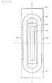
- FIG. 17is a plan view of the conventional loudspeaker with an elongated structure
- FIG. 18is a cross-sectional view of the loudspeaker in a long axis direction
- FIG. 19is a cross-sectional view of the loudspeaker in a short axis direction.
- a diaphragm 1which creates air vibration, has an elongated shape, and an outer circumference of the diaphragm 1 is supported to a frame 3 via an edge 2.
- a voice coil 4is fixed on a planar portion of the diaphragm 1.
- the frame 3includes in its center a magnetic circuit 8 consisting of a yoke 5, a magnet 6, and a top plate 7.
- the magnet 6is magnetized in a direction perpendicular to the diaphragm 1 (i.e., a direction of arrow Z shown in FIG. 19 ).
- a magnetic gap 9, where magnetic flux is generated in a direction perpendicular to the diaphragm 1,is formed between an opening of the yoke 5 (in the vicinity of the edge 2) and the top plate 7.
- the voice coil 4is located within the magnetic gap 9 in a direction perpendicular to the magnetic flux (i.e., a direction perpendicular to the sheet of FIG. 19 ). Accordingly, if an alternating current is applied to the voice coil 4, the diaphragm 1 is caused to vibrate in the direction of arrow Z shown in FIG. 19 , thereby emitting sound waves into space.
- a voice coilis bonded to a planar portion of a diaphragm by an adhesive.
- Each wire of the voice coilhas a circular cross section, and therefore an area of contact between the voice coil and the diaphragm is small.
- the adhesiveis easily spread into a thin sheet over the diaphragm, and therefore an adhesive layer made of the adhesive becomes thin. Due to the small contact area and the thin adhesive layer, adhesive strength between the voice coil and the diaphragm is small. Accordingly, the diaphragm and the voice coil are separated from each other, resulting in an increase in distortion of the diaphragm during vibration or causing insufficient vibration.
- the diaphragmis easily distorted during vibration, and therefore it is required to increase the adhesive strength between the diaphragm and the voice coil.
- a voice coil having a horizontally-elongated cross sectioni.e., if a vibration direction of the diaphragm corresponds to a vertical direction, the cross section of the voice coil is short in the vertical direction and long in the horizontal direction
- wires of the voice coilmight be separated from each other due to the vibration of the diaphragm. If the wires of the voice coil are separated from each other, reproduction sound quality is reduced.
- Document DE1930590is disclosing a loudspeaker with diaphragm having a groove with a concave cross section and a voice coil bounded directly to the diaphragm, whereby voice coil is placed in the groove.
- an object of the present inventionis to provide a loudspeaker with an elongated structure which is capable of increasing adhesive strength between a diaphragm and a coil.
- the present inventionhas the following features to attain the object mentioned above.
- a first aspect of the present inventionis directed to a loudspeaker including a diaphragm, an edge, a cushioning material, and a voice coil.
- the diaphragmincludes a groove having a concave cross section. Also, the diaphragm is in a horizontally or vertically elongated shape.
- the edgehas a roughly half-round shaped cross section and is coupled to an outer circumference of the diaphragm.
- the cushioning materialis bonded to the groove, and has a planar shape.
- the voice coilis bonded to the groove via the cushioning material.
- a cross section of the diaphragm along a longitudinal directionmay have a shape of an arc which is lower than the edge.
- the loudspeakermay include a diaphragm, an edge, and a voice coil.
- the diaphragmincludes a groove having a concave cross section. Also, the diaphragm is in a horizontally or vertically elongated shape.
- the edgehas a roughly half-round shaped cross section and is coupled to an outer circumference of the diaphragm.
- the voice coilis bonded to the groove. Here, the voice coil is thicker than a depth of the groove. Also, the voice coil has a cross section in which a dimension in a direction along a plane of the diaphragm is longer than a dimension in a direction perpendicular to the plane of the diaphragm.
- an adhesive for bonding the voice coil to the diaphragmmay be applied so as to form an adhesive fillet covering side surfaces of the voice coil.
- a plurality of protrusionswhich each are smaller than a diameter of a wire of the voice coil, may be provided on a bonding surface of the groove that is bonded to the voice coil.
- the loudspeakermay include a diaphragm, an edge, a voice coil, and a film.
- the diaphragmincludes a groove having a concave cross section. Also, the diaphragm is in a horizontally or vertically elongated shape.
- the edgehas a roughly half-round shaped cross section and is coupled to an outer circumference of the diaphragm.
- the voice coilis bonded to the groove.
- the filmis fixed on the diaphragm and the voice coil so as to cover the voice coil on a side opposite to a bonding surface of the diaphragm that is bonded to the voice coil.
- the filmis formed by, for example, any one of a polymer film, a polymer film having metal foil evaporated thereon, and the metal foil.
- the filmmay be made of a viscoelastic material.
- the diaphragmis configured so as to include a groove, it is possible to increase the adhesive strength between the voice coil and the diaphragm, thereby increasing reproduction sound quality of the loudspeaker. Further, a cushioning material is provided between the diaphragm and the voice coil, so that internal loss of the cushioning material prevents unnecessary resonance of the voice coil, thereby increasing sound quality of the loudspeaker.
- the diaphragmis formed so as to have an arc-shaped cross section, it is possible to increase the rigidity of the diaphragm as compared to a case where the diaphragms has a cross section formed by straight lines. Accordingly, it is possible to increase a high range resonance frequency of the diaphragm. Therefore, it is possible to provide a loudspeaker with a high reproduction characteristic.
- the adhesive for bonding the voice coil to the diaphragmis retained in the groove, so that the voice coil and the diaphragm can be bonded together with the adhesive of a sufficient thickness. Accordingly, as compared to a conventional structure, it is possible to increase adhesive strength between the voice coil and the diaphragm, thereby increasing reproduction sound quality of the loudspeaker. Also, in the second aspect, since the voice coil is bonded to the diaphragm so as to form a horizontally elongated shape, it is possible to reduce the thickness of the loudspeaker, while increasing the reproduction sound quality. Further, in the second aspect, it is possible to apply sufficient pressure to the diaphragm and the voice coil when bonding them together.
- the grooveincreases the rigidity of the diaphragm, and therefore it is possible to increase a high range resonance frequency of the diaphragm, whereby it is possible to provide a loudspeaker with a high reproduction characteristic.
- the adhesive for bonding the voice coil to the diaphragmis applied so as to form an adhesive fillet covering side surfaces of the voice coil, it is possible to further increase the adhesive strength between the voice coil and the diaphragm.
- the diaphragmis configured so as to include a groove, it is possible to increase the adhesive strength between the voice coil and the diaphragm, thereby increasing reproduction sound quality of the loudspeaker. Further, by sandwiching the voice coil between the diaphragm and a film, it is possible to increase the adhesive strength between the voice coil and the diaphragm.
- the filmis metal foil or a polymer film having the metal foil evaporated thereon, an heat conduction effect of the film reduces an increase in temperature of the voice coil. Accordingly, it is possible to realize a loudspeaker operable with greater input power.
- the filmis made of a viscoelastic material, internal loss of the film prevents unnecessary resonance of the voice coil. Accordingly, it is possible to further reduce distortion of the diaphragm during vibration.
- FIG. 1is a plan view of the loudspeaker
- FIG. 2is a cross-sectional view (an A-B cross-sectional view) of the loudspeaker in a long axis direction
- FIG. 3is a cross-sectional view (a C-D cross-sectional view) of the loudspeaker in a short axis direction.
- the loudspeakerincludes a diaphragm 101, an edge 102, a frame 104, a voice coil 105, a yoke 107, a magnet 108, and a top plate 109. As shown in FIG.
- the loudspeakerhas a shape which is elongated in a vertical (or horizontal) direction.
- a side of the loudspeaker on which the diaphragm 101 is provided(the left side in FIG. 2 ) is referred to as an "upper surface side”
- a side on which the yoke 107 is provided(the right side in FIG. 2 ) is referred to as a "lower surface side”.
- a longitudinal direction of the diaphragm 101which is roughly planar-shaped, is referred to as a "long axis direction”
- a direction perpendicular to the long axis directionis referred to as a "short axis direction”.
- the diaphragm 101is planar-shaped except in a portion where a groove 103, which will be described later, is provided.
- the diaphragm 101has a shape which is elongated in a vertical (or horizontal) direction. Specifically, the diaphragm 101 has a shape with two opposing parallel sides connected by arcs.
- the diaphragm 101is obtained by shaping a thin rigid film such as a polyimide material, or made of a paper material which is light and highly stiff.
- the edge 102is provided in the form of a loop around an outer circumference of the diaphragm 101. The edge 102 has a roughly half-round shaped cross section.
- An outer circumference of the edge 102is coupled to the frame 104 and the yoke 107.
- two end portions of the edge 102 in the long axis directionare coupled to the frame 104, and a central portion of the edge 102 in the long axis direction is coupled to the yoke 107.
- the diaphragm 101is supported to the frame 104 and the yoke 107 via the edge 102.
- a central portion of the frame 104 in the long axis directionis coupled to the yoke 107.
- the magnet 108is coupled to the upper surface side of yoke 107.
- the magnet 108is coupled to the upper surface side of the top plate 109.
- the yoke 107, the magnet 108, and the top plate 109form a magnetic circuit 110.
- the voice coil 105is bonded to the diaphragm 101 so as to be located in a magnetic gap formed by the magnetic circuit 110.
- the voice coil 105is structured by a plurality of turns of electric wires made of copper or aluminum silver covered with an insulating coating. In the structure as shown in FIGs. 1 through 3 , if an alternating current is applied to the voice coil 105, a drive force is generated in the voice coil 105 to cause the diaphragm 101 bonded to the voice coil 105 to vibrate, thereby emitting sound.
- the diaphragm 101has the groove 103 with a concave cross section (see FIGs. 2 and 3 ) .
- the voice coil 105is bonded by an adhesive 106 to the bottom of the concave portion of the groove 103.
- the groove 103is formed in a looped shape adapted to the shape of the voice coil 105.
- the shape of the voice coil 105 viewed from the upper surface sideis a rectangle elongated in the long axis direction, and therefore the groove 103 is formed in a rectangular shape (see FIG. 1 ).
- the groove 103is formed so as to be convex to the upper surface side so that the voice coil 105 is bonded to the diaphragm 101 on the lower surface side
- the groove 103may be formed so as to be convex to the lower surface side, such that the voice coil 105 is bonded to the diaphragm 101 on the upper surface side.
- the voice coil 105is bonded by the adhesive 106 to a portion of the diaphragm 101 where the groove 103 is provided. Since the groove 103 is formed so as to have a concave cross section, the adhesive 106 does not spread along the plane of the diaphragm 101, so that the adhesive 106 is retained on the bottom of the groove 103. Accordingly, the voice coil 105 and the diaphragm 101 can be bonded together with the adhesive 106 of a sufficient thickness, thereby increasing adhesive strength between the voice coil 105 and the diaphragm 101.
- the voice coil 105it is possible to prevent the voice coil 105 from being peeled off from the diaphragm 101 due to vibration of the diaphragm 101, thereby preventing a chattering sound from being made, while preventing distortion of the diaphragm from being increased during vibration. Thus, it is possible to increase reproduction sound quality.
- the voice coil 105is bonded to the diaphragm 101 so as to form a horizontally elongated shape. Specifically, the voice coil 105 is bonded to the diaphragm 101 such that in the cross section of the voice coil 105, a dimension in a direction along the planar portion of the diaphragm 101 is longer than a dimension in a direction perpendicular to the diaphragm 101 (see FIGs. 2 and 3 ). This is intended to reduce the thickness of the loudspeaker, and to increase contact between the voice coil 105 and the diaphragm 101, thereby causing the diaphragm 101 to vibrate with ideal piston motion.
- the voice coil 105has the horizontally-elongated shape
- the adhesive strength between the diaphragm 101 and the voice coil 105can be increased, and therefore there is substantially no possibility that the electric wires of the voice coil 105 are separated from each other.
- the loudspeaker according to the first embodimentit is possible to prevent the reproduction sound quality from being reduced.
- the voice coil 105is structured so as to be thicker than the depth of the groove 103 (see FIGs. 2 and 3 ).
- the groove 103is formed so as to be shallower than the thickness of the voice coil 105. This allows pressure to be applied to the diaphragm 101 and the voice coil 105 when bonding them together. Specifically, the diaphragm 101 and the voice coil 105 are caused to be in close contact with each other so as not to form a gap between them, whereby it is possible to more tightly bond them together.
- the diaphragm 101includes the groove 103 such that the voice coil 105 can be bonded at the location of the groove 103. Accordingly, it is possible to increase the adhesive strength between the diaphragm 101 and the voice coil 105, making it possible to increase reproduction sound quality.
- FIGs 4A and 4Bare graphs respectively showing a sound pressure frequency characteristic of a conventional loudspeaker and a sound pressure frequency characteristic of the loudspeaker according to the first embodiment. Specifically, FIG.
- FIG. 4Ais a graph showing a result of using a finite-element method (FEM) to analytically calculate a sound pressure frequency characteristic of a loudspeaker employing a conventional planar diaphragm as shown in FIG. 17 .
- FEMfinite-element method
- FIG. 4Bthe horizontal axis indicates frequencies, and the vertical axis indicates sound pressure levels.
- high range resonanceoccurs at a frequency of 10 kHz, and the sound pressure level decreases at higher frequencies, so that sound is not reproduced at a satisfactory level.
- FIG. 4Bis a graph showing a result of using the FEM to analytically calculate a sound pressure frequency characteristic of the loudspeaker according to the first embodiment. In FIG. 4B , resonance does not occur in a high frequency range, so that sound can be reproduced with a higher frequency compared to FIG. 4A .
- the diaphragm 101since the diaphragm 101 includes the groove 103, the rigidity of the diaphragm 101 can be increased, thereby increasing a high range resonance frequency. Particularly, in the diaphragm 101 with an elongated shape as shown in FIG. 1 , resonance readily occurs in the long axis direction. However, since the diaphragm 101 includes the groove 103, it is possible to reduce the resonance. Accordingly, in the first embodiment, satisfactory reproduction sound quality can be achieved even in a loudspeaker with an elongated structure.
- the present applicantproduced a loudspeaker with an elongated structure using an elongated diaphragm of 50.8 mm in length and 7.0 mm in width (the loudspeaker is 63 mm in length and 11 mm in width). It was confirmed that satisfactory reproduction sound quality can be achieved in the loudspeaker.
- the diaphragm 101since the diaphragm 101 includes the groove 103, it is possible to readily and accurately determine a location where the voice coil 105 is bonded to the diaphragm 101.
- the voice coil 105is situated in a location where the density of magnetic flux generated by the magnetic circuit 110 is high, and it is necessary for the voice coil 105 to be accurately attached in such a location.
- the groove 103plays a role of defining the location where the voice coil 105 is attached, and therefore the voice coil 105 can be accurately placed in a suitable location on the diaphragm 101.
- the voice coil 105is shown as being formed in two layers in a height direction (the vibration direction of the diaphragm 101), the voice coil 105 may be formed in one or more layers.
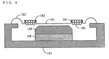
- FIG. 5is a cross-sectional view of the loudspeaker according to the second embodiment in the short axis direction.
- the loudspeaker according to the second embodimenthas an external appearance similar to that of the loudspeaker according to the first embodiment.
- a plan view of the loudspeakeris omitted since it is similar to FIG. 1 .
- FIG. 5corresponds to FIG. 3 in the first embodiment. Note that in FIG. 5 , elements similar to those shown in FIGs. 1 through 3 are denoted by the same reference numerals.
- the loudspeaker according to the second embodimentis described mainly with respect to differences from the loudspeaker according to the first embodiment.
- the voice coil 105is bonded to the bottom of the groove 103 of the diaphragm 101.
- an adhesive 201is applied so as to form an adhesive fillet covering side surfaces of the voice coil 105.
- the adhesive 201is applied so as to cover the side surfaces as well as the bottom of the voice coil 105 (a contact surface with the diaphragm 101).
- the adhesive filletmay be formed.
- FIGs. 6 and 7are views showing a loudspeaker of a third embodiment.
- FIG. 6is a plan view of the loudspeaker
- FIG. 7is a cross-sectional view (an E-F cross-sectional view) of the loudspeaker in the short axis direction.
- elements similar to those shown in FIGs. 1 through 3are denoted by the same reference numerals.
- the loudspeaker according to the third embodimentis described mainly with respect to differences from the loudspeaker according to the first embodiment.
- a plurality of protrusions 301are provided on the bottom of the groove 103 of the diaphragm 101. It is preferred that the protrusions 301 each are smaller (in height or width) than a diameter of a wire of the voice coil 105.
- the protrusions 301may be regularly or irregularly placed on the bottom of the groove 103. Also, the protrusions 301 may be convex to the upper or lower surface side of the diaphragm 101.
- a contact area between the adhesive 106 and the diaphragm 101is increased by the protrusions 301, thereby further increasing the adhesive strength between the diaphragm 101 and the voice coil 105.
- FIG. 8is a plan view of a variation of the loudspeaker according to the third embodiment.
- the ribs 302are provided in a direction perpendicular to a winding direction of the voice coil 105.
- the protrusions 301 or the ribs 302maybe provided to the diaphragm 101.
- FIG. 9is a cross-sectional view of the loudspeaker according to the fourth embodiment in the short axis direction.
- the loudspeaker according to the fourth embodimenthas an external appearance similar to that of the loudspeaker according to the first embodiment.
- a plan view of the loudspeakeris omitted since it is similar to FIG. 1 .
- FIG. 9corresponds to FIG. 3 in the first embodiment. Note that in FIG. 9 , elements similar to those shown in FIGs. 1 through 3 are denoted by the same reference numerals.
- the loudspeaker according to the fourth embodimentis described mainly with respect to differences from the loudspeaker according to the first embodiment.
- a polymer film 401is fixed on a surface of the voice coil 105 that is opposite to a bonding surface bonded to the diaphragm 101.
- the polymer film 401is fixed on the voice coil 105 and a planar portion of the diaphragm 101 so as to cover the voice coil 105.
- the voice coil 105is sandwiched by the polymer film 401 and the groove 103, thereby increasing the adhesive strength of the voice coil 105 and the diaphragm 101.
- a film 402 having metal foil 403 evaporated thereonmay be used instead of using the polymer film 401 (see FIG. 10 ).
- the metal foil 403aluminum or copper foil with satisfactory thermal conductivity is preferably used.
- the film 402 and the metal foil 403it is possible to achieve an effect similar to that achieved by providing the polymer film 401, and to increase thermal conductivity, thereby achieving an effect of preventing the temperature of the voice coil 105 from being increased, and increasing resistance to input overload.
- only metal foilmay be used instead of using the polymer film 401.
- FIG. 11is a cross-sectional view of the loudspeaker according to the fifth embodiment in the short axis direction.
- the loudspeaker according to the fifth embodimenthas an external appearance similar to that of the loudspeaker according to the first embodiment.
- a plan view of the loudspeakeris omitted since it is similar to FIG. 1 .
- FIG.11corresponds to FIG. 3 in the first embodiment. Note that in FIG. 11 , elements similar to those shown in FIGs. 1 through 3 are denoted by the same reference numerals.
- the loudspeaker according to the fifth embodimentis described mainly with respect to differences from the loudspeaker according to the first embodiment.
- an viscoelastic rubber sheet 501is fixed on the voice coil 105 and the planar portion of the diaphragm 101.
- the voice coil 105is sandwiched by the rubber sheet 501 and the groove 103, thereby increasing the adhesive strength between the voice coil 105 and the diaphragm 101 as in the fourth embodiment.
- the viscoelastic rubber sheet 501is used so that internal loss of the rubber sheet 501 prevents unnecessary resonance of the voice coil 105. Therefore, it is possible to further reduce the distortion of the diaphragm 101 during vibration.
- a viscoelastic polymer sheet, viscoelastic foam, or viscoelastic polymer foammay be used instead of using the rubber sheet 501.
- An effect similar to that achieved by using the rubber sheet 501can be achieved by using a viscoelastic material as mentioned here.
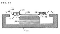
- a viscoelastic coating 502may be formed on a surface of the voice coil 105 (see FIG. 12 ). Specifically, a liquid viscoelastic body is applied and dried on the voice coil 105 to thinly form the viscoelastic coating 502 on the surface of the voice coil 105.
- a material for the viscoelastic coatinga polymer material with high internal loss (e.g., a material obtained by dissolving a rubber material, such as nitrile butadiene rubber (NBR) or styrene butadiene rubber (SBR), in a solvent) or an adhesive or metamorphous silicon of a water soluble emulsion type is preferably used.
- NBRnitrile butadiene rubber
- SBRstyrene butadiene rubber
- an adhesive or metamorphous silicon of a water soluble emulsion typeis preferably used.
- FIG. 13is a cross-sectional view of the loudspeaker according to the sixth embodiment in the short axis direction.
- the loudspeaker according to the sixth embodimenthas an external appearance similar to that of the loudspeaker according to the first embodiment.
- a plan view of the loudspeakeris omitted since it is similar to FIG. 1 .
- FIG. 13corresponds to FIG. 3 in the first embodiment. Note that in FIG. 13 , elements similar to those shown in FIGs. 1 through 3 are denoted by the same reference numerals.
- the loudspeaker according to the sixth embodimentis described mainly with respect to differences from the loudspeaker according to the first embodiment.
- the voice coil 105is bonded to the bottom of the groove 103 via a cushioning material 601. That is, the cushioning material 601 is bonded to the groove 103, and the voice coil 105 is bonded to the cushioning material 601.
- the cushioning material 601may be made of a heat-resisting sheet material such as paper or polyimide, or may be formed by a high viscoelastic sheet material such as rubber.
- the cushioning material 601 having a damping effectis placed between the voice coil 105 and the diaphragm 101, so that vibration of the voice coil 105 is transmitted through the cushioning material 601 to the diaphragm 101.
- the cushioning material 601prevents unnecessary resonance of the voice coil 105, thereby increasing sound quality of the loudspeaker. Moreover, if the high heat-resisting material is used as the cushioning material 601, heat generated by the voice coil 105 becomes hard to be transmitted to the diaphragm 101, whereby it is possible to increase the durability of the loudspeaker.
- a structure as described in the fourth or fifth embodimentmay be combined with the sixth embodiment.
- a surface of the voice coil 105which is opposite to a bonding surface bonded to the diaphragm 101, may be fixed to a film as described in the fourth or fifth embodiment.
- FIG. 14is a plan view of the loudspeaker
- FIG. 15is a cross-sectional view (a G-H cross-sectional view) of the loudspeaker in the long axis direction
- FIG. 16is a cross-sectional view (an I-J cross-sectional view) of the loudspeaker in the short axis direction. Note that in FIGs. 14 through 16 , elements similar to those in FIGs. 1 through 3 are denoted by the same reference numerals.
- the loudspeaker according to the seventh embodimentis described mainly with respect to differences from the loudspeaker according to the first embodiment.
- a diaphragm 701 having an arc-shaped cross section in the long axis directionis used instead of using the diaphragm 101 having a roughly planar shape.
- An edge 702is provided so as to form a loop around an outer circumference of the diaphragm 701. Similar to the edge 102 as described in the first embodiment, the edge 702 has a roughly half-round shape cross section.
- the edge 702is coupled at its outer circumference to the frame 104 and the yoke 107.
- the cross section of the diaphragm 701is in the shape of an arch in which a center portion is higher than end portions.
- the arc shape of the diaphragm 701is structured so as to be in the range less than or equal to the height of the edge 702.
- the seventh embodimentis similar to the first embodiment except that the cross section of the diaphragm 701 is arc-shaped.
- the diaphragm 701includes a groove 703 similar to the groove 103 as described in the first embodiment.
- the voice coil 105is bonded to the bottom of the groove 703.
- the diaphragm 701is formed to have an arc-shaped cross section, thereby increasing the flexural rigidity of the diaphragm. This increases the high range resonance frequency, thereby enlarging a reproduction bandwidth of the loudspeaker. That is, it is possible to provide a loudspeaker capable of reproducing sound with higher quality.
- the height of the arc shape of the diaphragm 701is less than or equal to the height of the edge 702, and therefore the diaphragm 701 does not influence the entire thickness of the loudspeaker. That is, forming the loudspeaker into an arc shape does not increase the thickness of the loudspeaker.
- the diaphragm 101 of the loudspeaker according to the first embodimentis replaced with the diaphragm 701 having the arch-shaped cross section
- the diaphragm 101 of the loudspeaker according to any one of the second through sixth embodimentsmay be replaced with the diaphragm 701.
- the present inventionprovides a loudspeaker which is capable of realizing reproduction sound with less distortion, and useful as a loudspeaker for use in a variety of types of audio apparatuses, particularly, in an audio visual apparatus. Moreover, the loudspeaker of the present invention can be used for sound reproduction in a portable terminal apparatus, for example.
Landscapes
- Engineering & Computer Science (AREA)
- Physics & Mathematics (AREA)
- Acoustics & Sound (AREA)
- Signal Processing (AREA)
- Multimedia (AREA)
- Diaphragms For Electromechanical Transducers (AREA)
- Audible-Bandwidth Dynamoelectric Transducers Other Than Pickups (AREA)
- Chair Legs, Seat Parts, And Backrests (AREA)
- Liquid Crystal (AREA)
- Surgical Instruments (AREA)
Abstract
Description
- The present invention relates to a loudspeaker, and more particularly to a loudspeaker for use in a variety of types of audio apparatuses, for example, an audio and visual apparatus.
- Conventionally, an audio and visual apparatus, such as a television, is configured so as to include loudspeakers on opposite sides of a cathode-ray tube. Accordingly, as the loudspeakers for use in the audio and visual apparatus, loudspeakers structured in an elongated shape, such as a rectangle, an ellipse, etc., are used. In recent years, as a display screen becomes wider, the loudspeakers for use in the audio and visual apparatus are required to become narrower, and also required to become thinner so as to be adapted to an apparatus with a thin depth, such as a liquid crystal display or a plasma display.
- Here, a conventional loudspeaker with an elongated structure is described with reference to
FIGs. 17 through 19 .FIG. 17 is a plan view of the conventional loudspeaker with an elongated structure,FIG. 18 is a cross-sectional view of the loudspeaker in a long axis direction, andFIG. 19 is a cross-sectional view of the loudspeaker in a short axis direction. InFIGs. 17 through 19 , adiaphragm 1, which creates air vibration, has an elongated shape, and an outer circumference of thediaphragm 1 is supported to aframe 3 via anedge 2. Avoice coil 4 is fixed on a planar portion of thediaphragm 1. - The
frame 3 includes in its center amagnetic circuit 8 consisting of ayoke 5, amagnet 6, and atop plate 7. InFIG. 19 , themagnet 6 is magnetized in a direction perpendicular to the diaphragm 1 (i.e., a direction of arrow Z shown inFIG. 19 ). Accordingly, amagnetic gap 9, where magnetic flux is generated in a direction perpendicular to thediaphragm 1, is formed between an opening of the yoke 5 (in the vicinity of the edge 2) and thetop plate 7. Thevoice coil 4 is located within themagnetic gap 9 in a direction perpendicular to the magnetic flux (i.e., a direction perpendicular to the sheet ofFIG. 19 ). Accordingly, if an alternating current is applied to thevoice coil 4, thediaphragm 1 is caused to vibrate in the direction of arrow Z shown inFIG. 19 , thereby emitting sound waves into space. - In a conventional loudspeaker, a voice coil is bonded to a planar portion of a diaphragm by an adhesive. Each wire of the voice coil has a circular cross section, and therefore an area of contact between the voice coil and the diaphragm is small. Also, the adhesive is easily spread into a thin sheet over the diaphragm, and therefore an adhesive layer made of the adhesive becomes thin. Due to the small contact area and the thin adhesive layer, adhesive strength between the voice coil and the diaphragm is small. Accordingly, the diaphragm and the voice coil are separated from each other, resulting in an increase in distortion of the diaphragm during vibration or causing insufficient vibration.
- Note that particularly in the loudspeaker with an elongated structure, the diaphragm is easily distorted during vibration, and therefore it is required to increase the adhesive strength between the diaphragm and the voice coil. Also, in a voice coil having a horizontally-elongated cross section (i.e., if a vibration direction of the diaphragm corresponds to a vertical direction, the cross section of the voice coil is short in the vertical direction and long in the horizontal direction), if the adhesive strength between the voice coil and the diaphragm is small, wires of the voice coil might be separated from each other due to the vibration of the diaphragm. If the wires of the voice coil are separated from each other, reproduction sound quality is reduced.
- Document
DE1930590 is disclosing a loudspeaker with diaphragm having a groove with a concave cross section and a voice coil bounded directly to the diaphragm, whereby voice coil is placed in the groove. - Therefore, an object of the present invention is to provide a loudspeaker with an elongated structure which is capable of increasing adhesive strength between a diaphragm and a coil.
- This object is solved by a loudspeaker having the features of
claim 1. Embodiments of the invention are described by the features ofclaims 2 to 8. - The present invention has the following features to attain the object mentioned above.
- A first aspect of the present invention is directed to a loudspeaker including a diaphragm, an edge, a cushioning material, and a voice coil. The diaphragm includes a groove having a concave cross section. Also, the diaphragm is in a horizontally or vertically elongated shape. The edge has a roughly half-round shaped cross section and is coupled to an outer circumference of the diaphragm. The cushioning material is bonded to the groove, and has a planar shape. The voice coil is bonded to the groove via the cushioning material.
- Note that a cross section of the diaphragm along a longitudinal direction may have a shape of an arc which is lower than the edge.
- According to a second aspect the loudspeaker may include a diaphragm, an edge, and a voice coil. The diaphragm includes a groove having a concave cross section. Also, the diaphragm is in a horizontally or vertically elongated shape. The edge has a roughly half-round shaped cross section and is coupled to an outer circumference of the diaphragm. The voice coil is bonded to the groove. Here, the voice coil is thicker than a depth of the groove. Also, the voice coil has a cross section in which a dimension in a direction along a plane of the diaphragm is longer than a dimension in a direction perpendicular to the plane of the diaphragm.
- Note that an adhesive for bonding the voice coil to the diaphragm may be applied so as to form an adhesive fillet covering side surfaces of the voice coil.
- Also, a plurality of protrusions, which each are smaller than a diameter of a wire of the voice coil, may be provided on a bonding surface of the groove that is bonded to the voice coil.
- According to a third aspect the loudspeaker may include a diaphragm, an edge, a voice coil, and a film. The diaphragm includes a groove having a concave cross section. Also, the diaphragm is in a horizontally or vertically elongated shape. The edge has a roughly half-round shaped cross section and is coupled to an outer circumference of the diaphragm. The voice coil is bonded to the groove. The film is fixed on the diaphragm and the voice coil so as to cover the voice coil on a side opposite to a bonding surface of the diaphragm that is bonded to the voice coil.
- Note that the film is formed by, for example, any one of a polymer film, a polymer film having metal foil evaporated thereon, and the metal foil.
- Also, the film may be made of a viscoelastic material.
- Further, in the first aspect, as in the second aspect, since the diaphragm is configured so as to include a groove, it is possible to increase the adhesive strength between the voice coil and the diaphragm, thereby increasing reproduction sound quality of the loudspeaker. Further, a cushioning material is provided between the diaphragm and the voice coil, so that internal loss of the cushioning material prevents unnecessary resonance of the voice coil, thereby increasing sound quality of the loudspeaker.
- Also, if the diaphragm is formed so as to have an arc-shaped cross section, it is possible to increase the rigidity of the diaphragm as compared to a case where the diaphragms has a cross section formed by straight lines. Accordingly, it is possible to increase a high range resonance frequency of the diaphragm. Therefore, it is possible to provide a loudspeaker with a high reproduction characteristic.
- In the second aspect, the adhesive for bonding the voice coil to the diaphragm is retained in the groove, so that the voice coil and the diaphragm can be bonded together with the adhesive of a sufficient thickness. Accordingly, as compared to a conventional structure, it is possible to increase adhesive strength between the voice coil and the diaphragm, thereby increasing reproduction sound quality of the loudspeaker. Also, in the second aspect, since the voice coil is bonded to the diaphragm so as to form a horizontally elongated shape, it is possible to reduce the thickness of the loudspeaker, while increasing the reproduction sound quality. Further, in the second aspect, it is possible to apply sufficient pressure to the diaphragm and the voice coil when bonding them together. Accordingly, it is possible to more tightly bond the diaphragm and the voice coil together. Furthermore, in the second aspect, the groove increases the rigidity of the diaphragm, and therefore it is possible to increase a high range resonance frequency of the diaphragm, whereby it is possible to provide a loudspeaker with a high reproduction characteristic.
- Also, if the adhesive for bonding the voice coil to the diaphragm is applied so as to form an adhesive fillet covering side surfaces of the voice coil, it is possible to further increase the adhesive strength between the voice coil and the diaphragm.
- Also, if protrusions are provided on the groove, a contact area between the adhesive and the diaphragm is increased, thereby further increasing the adhesive strength between the diaphragm and the voice coil.
- Further, in the third aspect, as in the second aspect, since the diaphragm is configured so as to include a groove, it is possible to increase the adhesive strength between the voice coil and the diaphragm, thereby increasing reproduction sound quality of the loudspeaker. Further, by sandwiching the voice coil between the diaphragm and a film, it is possible to increase the adhesive strength between the voice coil and the diaphragm.
- Also, if the film is metal foil or a polymer film having the metal foil evaporated thereon, an heat conduction effect of the film reduces an increase in temperature of the voice coil. Accordingly, it is possible to realize a loudspeaker operable with greater input power.
- Also, if the film is made of a viscoelastic material, internal loss of the film prevents unnecessary resonance of the voice coil. Accordingly, it is possible to further reduce distortion of the diaphragm during vibration.
- These and other objects, features, aspects and advantages of the present invention will become more apparent from the following detailed description of the present invention when taken in conjunction with the accompanying drawings.
FIG. 1 is a plan view of a loudspeaker according to a illustrative first embodiment;FIG. 2 is a cross-sectional view of the loudspeaker according to the first embodiment in a long axis direction;FIG. 3 is a cross-sectional view of the loudspeaker according to the first embodiment in a short axis direction;FIG. 4A is a graph showing a sound pressure frequency characteristic of a conventional loudspeaker;FIG. 4B is a graph showing a sound pressure frequency characteristic of the loudspeaker according to the first embodiment;FIG. 5 is a cross-sectional view of a loudspeaker according to a illustrative second embodiment in the short axis direction;FIG. 6 is a plan view of a loudspeaker according to a illustrative third embodiment;FIG. 7 is a cross-sectional view of the loudspeaker according to the third embodiment in the short axis direction;FIG. 8 is a plan view of a variation of the loudspeaker according to the third embodiment;FIG. 9 is a cross-sectional view of a loudspeaker according to a illustrative fourth embodiment in the short axis direction;FIG. 10 is a cross-sectional view of a variation of the loudspeaker according to the fourth embodiment in the short axis direction;FIG. 11 is a cross-sectional view of a loudspeaker according to a illustrative fifth embodiment in the short axis direction;FIG. 12 is a cross-sectional view of a variation of the loudspeaker according to the fifth embodiment in the short axis direction;FIG. 13 is a cross-sectional view of a loudspeaker according to a sixth embodiment in the short axis direction;FIG. 14 is a plan view of a loudspeaker according to a illustrative seventh embodiment;FIG. 15 is a cross-sectional view of the loudspeaker according to the seventh embodiment in the long axis direction;FIG. 16 is a cross-sectional view of the loudspeaker according to the seventh embodiment in the short axis direction;FIG. 17 is a plan view of a conventional loudspeaker with an elongated structure;FIG. 18 is a cross-sectional view of the conventional loudspeaker with an elongated structure in the long axis direction; andFIG. 19 is a cross-sectional view of the conventional loudspeaker with an elongated structure in the short axis direction.- A loudspeaker according to a illustrative first embodiment of the present invention is now described.
FIG. 1 is a plan view of the loudspeaker,FIG. 2 is a cross-sectional view (an A-B cross-sectional view) of the loudspeaker in a long axis direction, andFIG. 3 is a cross-sectional view (a C-D cross-sectional view) of the loudspeaker in a short axis direction. InFIGs. 1 through 3 , the loudspeaker includes adiaphragm 101, anedge 102, aframe 104, avoice coil 105, ayoke 107, amagnet 108, and atop plate 109. As shown inFIG. 1 , the loudspeaker has a shape which is elongated in a vertical (or horizontal) direction. Note that in the following descriptions, a side of the loudspeaker on which thediaphragm 101 is provided (the left side inFIG. 2 ) is referred to as an "upper surface side", and a side on which theyoke 107 is provided (the right side inFIG. 2 ) is referred to as a "lower surface side". Also, a longitudinal direction of thediaphragm 101, which is roughly planar-shaped, is referred to as a "long axis direction", and a direction perpendicular to the long axis direction is referred to as a "short axis direction". - As shown in
FIGs. 1 through 3 , thediaphragm 101 is planar-shaped except in a portion where agroove 103, which will be described later, is provided. Thediaphragm 101 has a shape which is elongated in a vertical (or horizontal) direction. Specifically, thediaphragm 101 has a shape with two opposing parallel sides connected by arcs. Thediaphragm 101 is obtained by shaping a thin rigid film such as a polyimide material, or made of a paper material which is light and highly stiff. Theedge 102 is provided in the form of a loop around an outer circumference of thediaphragm 101. Theedge 102 has a roughly half-round shaped cross section. An outer circumference of theedge 102 is coupled to theframe 104 and theyoke 107. In the first embodiment, two end portions of theedge 102 in the long axis direction (a top-to-bottom direction of the sheet ofFIG. 1 ) are coupled to theframe 104, and a central portion of theedge 102 in the long axis direction is coupled to theyoke 107. As such, thediaphragm 101 is supported to theframe 104 and theyoke 107 via theedge 102. - Also, as shown in
FIGs. 2 and3 , a central portion of theframe 104 in the long axis direction is coupled to theyoke 107. Themagnet 108 is coupled to the upper surface side ofyoke 107. Moreover, themagnet 108 is coupled to the upper surface side of thetop plate 109. Theyoke 107, themagnet 108, and thetop plate 109 form amagnetic circuit 110. Thevoice coil 105 is bonded to thediaphragm 101 so as to be located in a magnetic gap formed by themagnetic circuit 110. Thevoice coil 105 is structured by a plurality of turns of electric wires made of copper or aluminum silver covered with an insulating coating. In the structure as shown inFIGs. 1 through 3 , if an alternating current is applied to thevoice coil 105, a drive force is generated in thevoice coil 105 to cause thediaphragm 101 bonded to thevoice coil 105 to vibrate, thereby emitting sound. - Here, in the first embodiment, the
diaphragm 101 has thegroove 103 with a concave cross section (seeFIGs. 2 and3 ) . Thevoice coil 105 is bonded by an adhesive 106 to the bottom of the concave portion of thegroove 103. Thegroove 103 is formed in a looped shape adapted to the shape of thevoice coil 105. Specifically, in the first embodiment, the shape of thevoice coil 105 viewed from the upper surface side is a rectangle elongated in the long axis direction, and therefore thegroove 103 is formed in a rectangular shape (seeFIG. 1 ). Note that in the first embodiment, although thegroove 103 is formed so as to be convex to the upper surface side so that thevoice coil 105 is bonded to thediaphragm 101 on the lower surface side, thegroove 103 may be formed so as to be convex to the lower surface side, such that thevoice coil 105 is bonded to thediaphragm 101 on the upper surface side. - As described above, the
voice coil 105 is bonded by the adhesive 106 to a portion of thediaphragm 101 where thegroove 103 is provided. Since thegroove 103 is formed so as to have a concave cross section, the adhesive 106 does not spread along the plane of thediaphragm 101, so that the adhesive 106 is retained on the bottom of thegroove 103. Accordingly, thevoice coil 105 and thediaphragm 101 can be bonded together with the adhesive 106 of a sufficient thickness, thereby increasing adhesive strength between thevoice coil 105 and thediaphragm 101. Therefore, in the first embodiment, it is possible to prevent thevoice coil 105 from being peeled off from thediaphragm 101 due to vibration of thediaphragm 101, thereby preventing a chattering sound from being made, while preventing distortion of the diaphragm from being increased during vibration. Thus, it is possible to increase reproduction sound quality. - Also, in the first embodiment, the
voice coil 105 is bonded to thediaphragm 101 so as to form a horizontally elongated shape. Specifically, thevoice coil 105 is bonded to thediaphragm 101 such that in the cross section of thevoice coil 105, a dimension in a direction along the planar portion of thediaphragm 101 is longer than a dimension in a direction perpendicular to the diaphragm 101 (seeFIGs. 2 and3 ). This is intended to reduce the thickness of the loudspeaker, and to increase contact between thevoice coil 105 and thediaphragm 101, thereby causing thediaphragm 101 to vibrate with ideal piston motion. In the case where thevoice coil 105 has the horizontally-elongated shape, there is a possibility that electric wires of thevoice coil 105 might be easily separated from each other due to vibration of thediaphragm 101, resulting in reduction of reproduction sound quality. However, in the first embodiment, the adhesive strength between thediaphragm 101 and thevoice coil 105 can be increased, and therefore there is substantially no possibility that the electric wires of thevoice coil 105 are separated from each other. Thus, in the loudspeaker according to the first embodiment, it is possible to prevent the reproduction sound quality from being reduced. - Also, in the first embodiment, the
voice coil 105 is structured so as to be thicker than the depth of the groove 103 (seeFIGs. 2 and3 ). In other words, thegroove 103 is formed so as to be shallower than the thickness of thevoice coil 105. This allows pressure to be applied to thediaphragm 101 and thevoice coil 105 when bonding them together. Specifically, thediaphragm 101 and thevoice coil 105 are caused to be in close contact with each other so as not to form a gap between them, whereby it is possible to more tightly bond them together. - As described above, in the first embodiment, the
diaphragm 101 includes thegroove 103 such that thevoice coil 105 can be bonded at the location of thegroove 103. Accordingly, it is possible to increase the adhesive strength between thediaphragm 101 and thevoice coil 105, making it possible to increase reproduction sound quality. - Further, in the first embodiment, since the
diaphragm 101 includes thegroove 103, flexural rigidity of thediaphragm 101 can be increased, whereby it is possible to increase a resonance frequency (a high range resonance frequency) inherent to thediaphragm 101 which is generated in a high frequency range. Accordingly, it is possible to allow thediaphragm 101 to produce piston action with a higher frequency.FIGs 4A and 4B are graphs respectively showing a sound pressure frequency characteristic of a conventional loudspeaker and a sound pressure frequency characteristic of the loudspeaker according to the first embodiment. Specifically,FIG. 4A is a graph showing a result of using a finite-element method (FEM) to analytically calculate a sound pressure frequency characteristic of a loudspeaker employing a conventional planar diaphragm as shown inFIG. 17 . Note that inFIGs. 4A and 4B , the horizontal axis indicates frequencies, and the vertical axis indicates sound pressure levels. InFIG. 4A , high range resonance occurs at a frequency of 10 kHz, and the sound pressure level decreases at higher frequencies, so that sound is not reproduced at a satisfactory level.FIG. 4B is a graph showing a result of using the FEM to analytically calculate a sound pressure frequency characteristic of the loudspeaker according to the first embodiment. InFIG. 4B , resonance does not occur in a high frequency range, so that sound can be reproduced with a higher frequency compared toFIG. 4A . - As is apparent from
FIGs. 4A and 4B , in the first embodiment, since thediaphragm 101 includes thegroove 103, the rigidity of thediaphragm 101 can be increased, thereby increasing a high range resonance frequency. Particularly, in thediaphragm 101 with an elongated shape as shown inFIG. 1 , resonance readily occurs in the long axis direction. However, since thediaphragm 101 includes thegroove 103, it is possible to reduce the resonance. Accordingly, in the first embodiment, satisfactory reproduction sound quality can be achieved even in a loudspeaker with an elongated structure. Specifically, the present applicant produced a loudspeaker with an elongated structure using an elongated diaphragm of 50.8 mm in length and 7.0 mm in width (the loudspeaker is 63 mm in length and 11 mm in width). It was confirmed that satisfactory reproduction sound quality can be achieved in the loudspeaker. - Furthermore, in the first embodiment, since the
diaphragm 101 includes thegroove 103, it is possible to readily and accurately determine a location where thevoice coil 105 is bonded to thediaphragm 101. Here, it is preferred that thevoice coil 105 is situated in a location where the density of magnetic flux generated by themagnetic circuit 110 is high, and it is necessary for thevoice coil 105 to be accurately attached in such a location. In the first embodiment, thegroove 103 plays a role of defining the location where thevoice coil 105 is attached, and therefore thevoice coil 105 can be accurately placed in a suitable location on thediaphragm 101. Moreover, it is possible to reduce variation in location where thevoice coil 105 is attached among individual loudspeakers, whereby it is possible to reduce variation in reproduction sound pressure level among the individual loudspeakers. - Note that in
FIGs. 2 and3 , although thevoice coil 105 is shown as being formed in two layers in a height direction (the vibration direction of the diaphragm 101), thevoice coil 105 may be formed in one or more layers. - Described next is a loudspeaker according to a illustrative second embodiment.
FIG. 5 is a cross-sectional view of the loudspeaker according to the second embodiment in the short axis direction. Note that the loudspeaker according to the second embodiment has an external appearance similar to that of the loudspeaker according to the first embodiment. A plan view of the loudspeaker is omitted since it is similar toFIG. 1 .FIG. 5 corresponds toFIG. 3 in the first embodiment. Note that inFIG. 5 , elements similar to those shown inFIGs. 1 through 3 are denoted by the same reference numerals. Hereinbelow, the loudspeaker according to the second embodiment is described mainly with respect to differences from the loudspeaker according to the first embodiment. - In the second embodiment, as in the first embodiment, the
voice coil 105 is bonded to the bottom of thegroove 103 of thediaphragm 101. Here, in the second embodiment, an adhesive 201 is applied so as to form an adhesive fillet covering side surfaces of thevoice coil 105. Specifically, the adhesive 201 is applied so as to cover the side surfaces as well as the bottom of the voice coil 105 (a contact surface with the diaphragm 101). In the second embodiment, it is possible to increase the adhesive strength between thediaphragm 101 and thevoice coil 105. Note that in third through seventh embodiments which will be later, the adhesive fillet may be formed. - Described next is a loudspeaker according to a illustrative third embodiment.
FIGs. 6 and7 are views showing a loudspeaker of a third embodiment. Specifically,FIG. 6 is a plan view of the loudspeaker, andFIG. 7 is a cross-sectional view (an E-F cross-sectional view) of the loudspeaker in the short axis direction. Note that inFIGs. 6 and7 , elements similar to those shown inFIGs. 1 through 3 are denoted by the same reference numerals. Hereinbelow, the loudspeaker according to the third embodiment is described mainly with respect to differences from the loudspeaker according to the first embodiment. - In the third embodiment, a plurality of
protrusions 301 are provided on the bottom of thegroove 103 of thediaphragm 101. It is preferred that theprotrusions 301 each are smaller (in height or width) than a diameter of a wire of thevoice coil 105. Theprotrusions 301 may be regularly or irregularly placed on the bottom of thegroove 103. Also, theprotrusions 301 may be convex to the upper or lower surface side of thediaphragm 101. In the third embodiment, a contact area between the adhesive 106 and thediaphragm 101 is increased by theprotrusions 301, thereby further increasing the adhesive strength between thediaphragm 101 and thevoice coil 105. - Note that in the third embodiment, instead of providing the
protrusions 301,ribs 302 may be provided on the bottom of thegroove 103.FIG. 8 is a plan view of a variation of the loudspeaker according to the third embodiment. InFIG. 8 , theribs 302 are provided in a direction perpendicular to a winding direction of thevoice coil 105. By providing theribs 302 to thediaphragm 101, it is possible to achieve an effect similar to that achieved by providing theprotrusions 301 to thediaphragm 101. - Note that in fourth through seventh embodiments which will be described, the
protrusions 301 or theribs 302 maybe provided to thediaphragm 101. - Described next is a loudspeaker according to a illustrative fourth embodiment.
FIG. 9 is a cross-sectional view of the loudspeaker according to the fourth embodiment in the short axis direction. Note that the loudspeaker according to the fourth embodiment has an external appearance similar to that of the loudspeaker according to the first embodiment. A plan view of the loudspeaker is omitted since it is similar toFIG. 1 .FIG. 9 corresponds toFIG. 3 in the first embodiment. Note that inFIG. 9 , elements similar to those shown inFIGs. 1 through 3 are denoted by the same reference numerals. Hereinbelow, the loudspeaker according to the fourth embodiment is described mainly with respect to differences from the loudspeaker according to the first embodiment. - In
FIG. 9 , apolymer film 401 is fixed on a surface of thevoice coil 105 that is opposite to a bonding surface bonded to thediaphragm 101. Thepolymer film 401 is fixed on thevoice coil 105 and a planar portion of thediaphragm 101 so as to cover thevoice coil 105. As shown inFIG. 9 , in the fourth embodiment, thevoice coil 105 is sandwiched by thepolymer film 401 and thegroove 103, thereby increasing the adhesive strength of thevoice coil 105 and thediaphragm 101. - Note that in the fourth embodiment, a
film 402 havingmetal foil 403 evaporated thereon may be used instead of using the polymer film 401 (seeFIG. 10 ). Note that as themetal foil 403, aluminum or copper foil with satisfactory thermal conductivity is preferably used. By using thefilm 402 and themetal foil 403, it is possible to achieve an effect similar to that achieved by providing thepolymer film 401, and to increase thermal conductivity, thereby achieving an effect of preventing the temperature of thevoice coil 105 from being increased, and increasing resistance to input overload. Alternatively, instead of using thepolymer film 401, only metal foil may be used. - Described next is a loudspeaker according to a illustrative fifth embodiment.
FIG. 11 is a cross-sectional view of the loudspeaker according to the fifth embodiment in the short axis direction. Note that the loudspeaker according to the fifth embodiment has an external appearance similar to that of the loudspeaker according to the first embodiment. A plan view of the loudspeaker is omitted since it is similar toFIG. 1 .FIG.11 corresponds toFIG. 3 in the first embodiment. Note that inFIG. 11 , elements similar to those shown inFIGs. 1 through 3 are denoted by the same reference numerals. Hereinbelow, the loudspeaker according to the fifth embodiment is described mainly with respect to differences from the loudspeaker according to the first embodiment. - In the fifth embodiment, instead of the
polymer film 401, anviscoelastic rubber sheet 501 is fixed on thevoice coil 105 and the planar portion of thediaphragm 101. Specifically, in the fifth embodiment, thevoice coil 105 is sandwiched by therubber sheet 501 and thegroove 103, thereby increasing the adhesive strength between thevoice coil 105 and thediaphragm 101 as in the fourth embodiment. Moreover, in the fifth embodiment, theviscoelastic rubber sheet 501 is used so that internal loss of therubber sheet 501 prevents unnecessary resonance of thevoice coil 105. Therefore, it is possible to further reduce the distortion of thediaphragm 101 during vibration. - Note that in the fifth embodiment, instead of using the
rubber sheet 501, a viscoelastic polymer sheet, viscoelastic foam, or viscoelastic polymer foam may be used. An effect similar to that achieved by using therubber sheet 501 can be achieved by using a viscoelastic material as mentioned here. Alternatively, instead of using therubber sheet 501, aviscoelastic coating 502 may be formed on a surface of the voice coil 105 (seeFIG. 12 ). Specifically, a liquid viscoelastic body is applied and dried on thevoice coil 105 to thinly form theviscoelastic coating 502 on the surface of thevoice coil 105. Note that as a material for the viscoelastic coating, a polymer material with high internal loss (e.g., a material obtained by dissolving a rubber material, such as nitrile butadiene rubber (NBR) or styrene butadiene rubber (SBR), in a solvent) or an adhesive or metamorphous silicon of a water soluble emulsion type is preferably used. By using theviscoelastic coating 502, it is possible to achieve an effect similar to that achieved by using therubber sheet 501. Note that inFIG. 12 , although the adhesive 201 is provided as the adhesive fillet on the side surfaces of thevoice coil 105, the adhesive 201 does not have to be provided as the adhesive fillet. - Described next is a loudspeaker according to a sixth embodiment.
FIG. 13 is a cross-sectional view of the loudspeaker according to the sixth embodiment in the short axis direction. Note that the loudspeaker according to the sixth embodiment has an external appearance similar to that of the loudspeaker according to the first embodiment. A plan view of the loudspeaker is omitted since it is similar toFIG. 1 .FIG. 13 corresponds toFIG. 3 in the first embodiment. Note that inFIG. 13 , elements similar to those shown inFIGs. 1 through 3 are denoted by the same reference numerals. Hereinbelow, the loudspeaker according to the sixth embodiment is described mainly with respect to differences from the loudspeaker according to the first embodiment. - In the sixth embodiment, the
voice coil 105 is bonded to the bottom of thegroove 103 via acushioning material 601. That is, thecushioning material 601 is bonded to thegroove 103, and thevoice coil 105 is bonded to thecushioning material 601. Thecushioning material 601 may be made of a heat-resisting sheet material such as paper or polyimide, or may be formed by a high viscoelastic sheet material such as rubber. In the sixth embodiment, thecushioning material 601 having a damping effect is placed between thevoice coil 105 and thediaphragm 101, so that vibration of thevoice coil 105 is transmitted through thecushioning material 601 to thediaphragm 101. Specifically, internal loss of thecushioning material 601 prevents unnecessary resonance of thevoice coil 105, thereby increasing sound quality of the loudspeaker. Moreover, if the high heat-resisting material is used as thecushioning material 601, heat generated by thevoice coil 105 becomes hard to be transmitted to thediaphragm 101, whereby it is possible to increase the durability of the loudspeaker. - Note that a structure as described in the fourth or fifth embodiment may be combined with the sixth embodiment. Specifically, in the sixth embodiment, a surface of the
voice coil 105, which is opposite to a bonding surface bonded to thediaphragm 101, may be fixed to a film as described in the fourth or fifth embodiment. - Described next is a loudspeaker according to a illustrative seventh embodiment.
FIG. 14 is a plan view of the loudspeaker,FIG. 15 is a cross-sectional view (a G-H cross-sectional view) of the loudspeaker in the long axis direction, andFIG. 16 is a cross-sectional view (an I-J cross-sectional view) of the loudspeaker in the short axis direction. Note that inFIGs. 14 through 16 , elements similar to those inFIGs. 1 through 3 are denoted by the same reference numerals. Hereinbelow, the loudspeaker according to the seventh embodiment is described mainly with respect to differences from the loudspeaker according to the first embodiment. - In the seventh embodiment, instead of using the
diaphragm 101 having a roughly planar shape, adiaphragm 701 having an arc-shaped cross section in the long axis direction is used. Anedge 702 is provided so as to form a loop around an outer circumference of thediaphragm 701. Similar to theedge 102 as described in the first embodiment, theedge 702 has a roughly half-round shape cross section. Theedge 702 is coupled at its outer circumference to theframe 104 and theyoke 107. - As shown in
FIG. 15 , the cross section of thediaphragm 701 is in the shape of an arch in which a center portion is higher than end portions. The arc shape of thediaphragm 701 is structured so as to be in the range less than or equal to the height of theedge 702. The seventh embodiment is similar to the first embodiment except that the cross section of thediaphragm 701 is arc-shaped. Specifically, thediaphragm 701 includes agroove 703 similar to thegroove 103 as described in the first embodiment. Thevoice coil 105 is bonded to the bottom of thegroove 703. - In the seventh embodiment, the
diaphragm 701 is formed to have an arc-shaped cross section, thereby increasing the flexural rigidity of the diaphragm. This increases the high range resonance frequency, thereby enlarging a reproduction bandwidth of the loudspeaker. That is, it is possible to provide a loudspeaker capable of reproducing sound with higher quality. Further, the height of the arc shape of thediaphragm 701 is less than or equal to the height of theedge 702, and therefore thediaphragm 701 does not influence the entire thickness of the loudspeaker. That is, forming the loudspeaker into an arc shape does not increase the thickness of the loudspeaker. - Note that in the seventh embodiment, although the
diaphragm 101 of the loudspeaker according to the first embodiment is replaced with thediaphragm 701 having the arch-shaped cross section, thediaphragm 101 of the loudspeaker according to any one of the second through sixth embodiments may be replaced with thediaphragm 701. - The present invention provides a loudspeaker which is capable of realizing reproduction sound with less distortion, and useful as a loudspeaker for use in a variety of types of audio apparatuses, particularly, in an audio visual apparatus. Moreover, the loudspeaker of the present invention can be used for sound reproduction in a portable terminal apparatus, for example.
- While the invention has been described in detail, the foregoing description is in all aspects illustrative and not restrictive. It is understood that numerous other modifications and variations can be devised without departing from the scope of the invention.
Claims (8)
- A loudspeaker comprising:an elongated diaphragm (101; 701) including a groove (103) having a concave cross section;an edge (102) having a half-round shaped cross section and coupled to an outer circumference of the diaphragm (101; 701);a planar cushioning material (601) bonded to the groove (103); anda voice coil (105) bonded to the groove (103) via the cushioning material.
- A loudspeaker according to claim 1, wherein a cross section of the diaphragm (101; 701) along the elongated direction has a shape of an arc which is lower than the edge.
- A loudspeaker according to claim 1, wherein the voice coil (105) is thicker than a depth of the groove (103).
- A loudspeaker according to claim 1, wherein the voice coil (105) has a cross section in which a dimension in a direction along a plane of the diaphragm (101; 701) is longer than a dimension in a direction perpendicular to the plane of the diaphragm (101; 701).
- A loudspeaker according to claim 1, wherein an adhesive (201) for bonding the voice coil (105) to the diaphragm (101; 701) is applied so as to form an adhesive fillet covering side surfaces of the voice coil (105).
- A loudspeaker according to claim 1, wherein a film (401; 402; 403; 501; 502)is fixed on the diaphragm (101; 701) and the voice coil (105) so as to cover the voice coil (105) on a side opposite to a bonding surface of the diaphragm (101; 701) that is bonded to the voice coil (105).
- A loudspeaker according to claim 6, wherein the film is formed by any one of a polymer film, a polymer film having metal foil evaporated thereon, and the metal foil.
- A loudspeaker according to claim 6, wherein the film is made of a viscoelastic material.
Applications Claiming Priority (2)
| Application Number | Priority Date | Filing Date | Title |
|---|---|---|---|
| JP2003295108 | 2003-08-19 | ||
| EP04018936AEP1519621B1 (en) | 2003-08-19 | 2004-08-10 | Loudspeaker |
Related Parent Applications (1)
| Application Number | Title | Priority Date | Filing Date |
|---|---|---|---|
| EP04018936ADivisionEP1519621B1 (en) | 2003-08-19 | 2004-08-10 | Loudspeaker |
Publications (3)
| Publication Number | Publication Date |
|---|---|
| EP1662839A2 EP1662839A2 (en) | 2006-05-31 |
| EP1662839A3 EP1662839A3 (en) | 2006-06-07 |
| EP1662839B1true EP1662839B1 (en) | 2008-05-07 |
Family
ID=34191078
Family Applications (3)
| Application Number | Title | Priority Date | Filing Date |
|---|---|---|---|
| EP06002706AExpired - LifetimeEP1662838B1 (en) | 2003-08-19 | 2004-08-10 | Loudspeaker |
| EP04018936AExpired - LifetimeEP1519621B1 (en) | 2003-08-19 | 2004-08-10 | Loudspeaker |
| EP06002707AExpired - LifetimeEP1662839B1 (en) | 2003-08-19 | 2004-08-10 | Loudspeaker |
Family Applications Before (2)
| Application Number | Title | Priority Date | Filing Date |
|---|---|---|---|
| EP06002706AExpired - LifetimeEP1662838B1 (en) | 2003-08-19 | 2004-08-10 | Loudspeaker |
| EP04018936AExpired - LifetimeEP1519621B1 (en) | 2003-08-19 | 2004-08-10 | Loudspeaker |
Country Status (6)
| Country | Link |
|---|---|
| US (1) | US7447328B2 (en) |
| EP (3) | EP1662838B1 (en) |
| KR (1) | KR101073245B1 (en) |
| CN (1) | CN1585565B (en) |
| AT (3) | ATE394895T1 (en) |
| DE (3) | DE602004013604D1 (en) |
Families Citing this family (26)
| Publication number | Priority date | Publication date | Assignee | Title |
|---|---|---|---|---|
| DE602004013604D1 (en)* | 2003-08-19 | 2008-06-19 | Matsushita Electric Industrial Co Ltd | speaker |
| US7510047B2 (en)* | 2004-03-05 | 2009-03-31 | Keiko Muto | Speaker edge and resonator panel assembly |
| KR20070007866A (en)* | 2004-04-29 | 2007-01-16 | 코닌클리즈케 필립스 일렉트로닉스 엔.브이. | Diaphragm for loudspeaker, loudspeaker with diaphragm and apparatus including loudspeaker |
| JP4948001B2 (en)* | 2005-03-09 | 2012-06-06 | 古河電気工業株式会社 | Diaphragm for flat speaker |
| WO2006098243A1 (en)* | 2005-03-14 | 2006-09-21 | Matsushita Electric Industrial Co., Ltd. | Speaker |
| KR100753219B1 (en)* | 2005-04-12 | 2007-08-30 | 크레신 주식회사 | speaker |
| JP4677341B2 (en)* | 2005-12-21 | 2011-04-27 | パイオニア株式会社 | Speaker device and mobile phone |
| JP2007174233A (en)* | 2005-12-21 | 2007-07-05 | Pioneer Electronic Corp | Speaker instrument and portable telephone |
| US8031901B2 (en)* | 2006-09-14 | 2011-10-04 | Bohlender Graebener Corporation | Planar speaker driver |
| US8116512B2 (en) | 2006-09-14 | 2012-02-14 | Bohlender Graebener Corporation | Planar speaker driver |
| US8259987B2 (en)* | 2007-01-11 | 2012-09-04 | Victor Company Of Japan, Ltd. | Diaphragm, diaphragm assembly and electroacoustic transducer |
| CN102057690A (en)* | 2008-07-10 | 2011-05-11 | 日本先锋公司 | speaker device |
| JP2012010148A (en)* | 2010-06-25 | 2012-01-12 | Sanyo Electric Co Ltd | Electro-acoustic converter |
| CN202004956U (en)* | 2010-12-31 | 2011-10-05 | 瑞声光电科技(常州)有限公司 | Acoustic generator |
| CN103200500A (en)* | 2012-01-04 | 2013-07-10 | 苏州恒听电子有限公司 | Flapping device used for minitype loudspeaker device |
| CN103347233B (en)* | 2013-06-14 | 2016-08-24 | 歌尔声学股份有限公司 | The diaphragm of loudspeaker |
| US9584886B2 (en)* | 2014-07-16 | 2017-02-28 | Htc Corporation | Micro-speaker |
| US20170318391A1 (en)* | 2014-11-08 | 2017-11-02 | Slivice Co., Ltd | Diaphragm for speaker apparatus |
| CN104540078A (en)* | 2014-12-16 | 2015-04-22 | 歌尔声学股份有限公司 | Micro loudspeaker |
| US20160192079A1 (en)* | 2014-12-31 | 2016-06-30 | Knowles Ipc (M) Sdn. Bhd. | Rotary flux acoustic transducer |
| JP7022550B2 (en)* | 2017-09-28 | 2022-02-18 | パナソニック株式会社 | Electroacoustic transducer |
| CN113497999B (en)* | 2020-03-19 | 2023-04-11 | 华为技术有限公司 | Speaker and electronic equipment |
| US11289786B2 (en)* | 2020-06-03 | 2022-03-29 | Acoustic Metamaterials LLC | Metamaterial loudspeaker diaphragm |
| CN111954135B (en)* | 2020-08-19 | 2025-02-14 | 苏州礼乐乐器股份有限公司 | A full-band high-quality electronic product speaker with sound beam and sound tunnel |
| CN112969132B (en)* | 2021-01-29 | 2023-01-24 | 歌尔股份有限公司 | Elastic support piece, electronic device and terminal |
| CN115914953A (en)* | 2021-09-22 | 2023-04-04 | 歌尔科技有限公司 | Speaker and electronic apparatus |
Family Cites Families (61)
| Publication number | Priority date | Publication date | Assignee | Title |
|---|---|---|---|---|
| US2392143A (en)* | 1942-11-30 | 1946-01-01 | Rca Corp | Loud-speaker |
| NL73443C (en)* | 1949-03-31 | |||
| US2775653A (en)* | 1950-11-16 | 1956-12-25 | Holmberg & Co | Moving coil diaphragms for electrodynamic listening apparatus |
| DE952649C (en)* | 1950-11-16 | 1956-11-22 | Holmberg & Co | Moving coil membrane for electrodynamic hearing aids |
| DE1174364B (en)* | 1963-08-14 | 1964-07-23 | Telefunken Patent | Voice coil for electroacoustic transducers |
| DE1930590A1 (en)* | 1969-06-16 | 1970-12-23 | Siemens Ag | Voice coil for dynamic converter |
| US4088847A (en)* | 1975-12-11 | 1978-05-09 | Matsushita Electric Industrial Co., Ltd. | Speaker voice coil construction |
| JPS5739697A (en) | 1980-08-22 | 1982-03-04 | Pioneer Electronic Corp | Dynamic speaker |
| US4376233A (en)* | 1980-12-18 | 1983-03-08 | Sony Corporation | Securing of lead wires to electro-acoustic transducers |
| JPS58119298A (en)* | 1982-01-09 | 1983-07-15 | Noboru Denki Seisakusho:Kk | Diaphragm for speaker |
| GB2114855B (en)* | 1982-02-09 | 1985-10-23 | Standard Telephones Cables Ltd | Moving coil transducer |
| JPS5932294A (en) | 1982-08-18 | 1984-02-21 | Nissan Shatai Co Ltd | Diaphragm construction of flat speaker |
| US5472736A (en)* | 1991-06-03 | 1995-12-05 | Read-Rite Corporation | Method of making a bi-level coil for a thin film magnetic transducer |
| JPH0538639A (en) | 1991-08-02 | 1993-02-19 | Mazda Motor Corp | Method and device for transporting tire |
| CA2147684C (en)* | 1994-04-25 | 1998-12-08 | Akihiro Furuta | Loudspeaker |
| JP3213521B2 (en)* | 1994-09-12 | 2001-10-02 | 三洋電機株式会社 | Electroacoustic transducer |
| US5764784A (en) | 1994-09-12 | 1998-06-09 | Sanyo Electric Co., Ltd. | Electroacoustic transducer |
| JPH07288894A (en)* | 1995-03-09 | 1995-10-31 | Sony Corp | Voice coil bobbin |
| JP3136959B2 (en)* | 1995-08-31 | 2001-02-19 | 松下電器産業株式会社 | Speaker |
| JP3893694B2 (en) | 1996-10-30 | 2007-03-14 | 松下電器産業株式会社 | Speaker |
| JP3337631B2 (en)* | 1997-11-10 | 2002-10-21 | パイオニア株式会社 | Dome speaker and manufacturing method thereof |
| JP3812150B2 (en)* | 1998-06-18 | 2006-08-23 | 松下電器産業株式会社 | Speaker |
| JP3704977B2 (en) | 1998-11-20 | 2005-10-12 | 松下電器産業株式会社 | Electro-mechanical-acoustic transducer |
| GB2345402B (en)* | 1998-12-28 | 2000-12-20 | Foster Electric Co Ltd | Improvements in loudspeakers |
| EP1116413B1 (en)* | 1999-03-10 | 2006-01-18 | Koninklijke Philips Electronics N.V. | Apparatus including an electroacoustic transducer having terminal contacts which extend in the direction of the transducer axis and including a printed circuit board having mating contacts |
| JP2003516648A (en)* | 1999-07-23 | 2003-05-13 | デジタル ソニックス,リミティド ライアビリティー カンパニー | Flat panel speaker |
| US20050286729A1 (en)* | 1999-07-23 | 2005-12-29 | George Harwood | Flat speaker with a flat membrane diaphragm |
| KR100354376B1 (en)* | 1999-12-08 | 2002-09-28 | 에스텍 주식회사 | Speaker having a device capable of generating both sound and vibration |
| JP3619736B2 (en)* | 2000-02-25 | 2005-02-16 | スター精密株式会社 | Speaker |
| EP1128705B1 (en)* | 2000-02-25 | 2009-05-06 | Star Micronics Co., Ltd. | Speaker |
| US6303469B1 (en)* | 2000-06-07 | 2001-10-16 | Micron Technology, Inc. | Thin microelectronic substrates and methods of manufacture |
| AU2001279203A1 (en)* | 2000-07-31 | 2002-02-13 | Harman International Industries Inc. | Loudspeaker coil suspension system |
| US6654475B2 (en)* | 2000-09-29 | 2003-11-25 | Victor Company Of Japan, Ltd. | Electricity-to-sound transducer |
| US6636612B1 (en)* | 2000-11-03 | 2003-10-21 | Algo Sound, Inc. | Speaker for use in confined spaces |
| JP4557412B2 (en)* | 2000-11-20 | 2010-10-06 | パナソニック株式会社 | Speaker |
| JP4233745B2 (en)* | 2000-12-05 | 2009-03-04 | パイオニア株式会社 | Speaker device |
| JP3935393B2 (en) | 2001-05-08 | 2007-06-20 | 松下電器産業株式会社 | Speaker and portable terminal device |
| US6714655B2 (en)* | 2001-05-11 | 2004-03-30 | Matsushita Electric Industrial Co., Ltd. | Speaker |
| US6678387B2 (en)* | 2001-10-30 | 2004-01-13 | Alpine Electronics, Inc. | Loudspeaker having cooling system |
| JP4006981B2 (en)* | 2001-11-16 | 2007-11-14 | 松下電器産業株式会社 | Speaker |
| US7283636B2 (en)* | 2002-02-28 | 2007-10-16 | The Furukawa Electric Co., Ltd. | Planar speaker |
| JP2003320919A (en) | 2002-05-08 | 2003-11-11 | Nissan Motor Co Ltd | Automotive airbag device for head protection |
| DE10222265B4 (en)* | 2002-05-18 | 2013-02-07 | Preh Gmbh | Leitkleberverbindung |
| JP3896900B2 (en)* | 2002-05-28 | 2007-03-22 | ソニー株式会社 | Speaker device |
| EP1377115B1 (en)* | 2002-06-24 | 2016-01-06 | Panasonic Intellectual Property Management Co., Ltd. | Loudspeaker diaphragm |
| WO2004004410A1 (en)* | 2002-06-26 | 2004-01-08 | Matsushita Electric Industrial Co., Ltd. | Loudspeaker edge |
| EP1562397B1 (en)* | 2002-10-24 | 2013-12-04 | Panasonic Corporation | Electroacoustic transducer with vibration function and its manufacturing method |
| US20040081131A1 (en)* | 2002-10-25 | 2004-04-29 | Walton Jay Rod | OFDM communication system with multiple OFDM symbol sizes |
| CN1602648B (en)* | 2002-11-28 | 2010-04-21 | 松下电器产业株式会社 | Loudspeaker |
| DE10303030A1 (en)* | 2003-01-25 | 2004-08-05 | Norman Gerkinsmeyer | driver |
| JP4323881B2 (en)* | 2003-06-27 | 2009-09-02 | パイオニア株式会社 | Speaker device |
| DE602004013604D1 (en)* | 2003-08-19 | 2008-06-19 | Matsushita Electric Industrial Co Ltd | speaker |
| JP4196089B2 (en)* | 2003-08-29 | 2008-12-17 | パナソニック株式会社 | Speaker device |
| EP1571876A4 (en)* | 2003-12-22 | 2010-05-12 | Panasonic Corp | SPEAKER AND DEVICE USING THE SAME |
| JP4439283B2 (en)* | 2004-02-10 | 2010-03-24 | パイオニア株式会社 | Oval or elliptical speaker device |
| JP2005277874A (en)* | 2004-03-25 | 2005-10-06 | Pioneer Electronic Corp | Coaxial speaker device and manufacturing method thereof |
| KR100616593B1 (en)* | 2004-07-02 | 2006-08-28 | 삼성전기주식회사 | Multifunctional actuator with vibration prevention |
| JP3846497B2 (en)* | 2004-09-21 | 2006-11-15 | オンキヨー株式会社 | Speaker diaphragm and speaker with the same |
| TW200629959A (en)* | 2004-09-22 | 2006-08-16 | Citizen Electronics | Electro-dynamic exciter |
| US20060078154A1 (en)* | 2004-10-11 | 2006-04-13 | Yang Ho-Joon | Electricalacoustic ransducer |
| US20060110001A1 (en)* | 2004-11-24 | 2006-05-25 | Stephen Saint Vincent | Inertial voice type coil actuator systems |
- 2004
- 2004-08-10DEDE602004013604Tpatent/DE602004013604D1/ennot_activeExpired - Lifetime
- 2004-08-10ATAT06002707Tpatent/ATE394895T1/ennot_activeIP Right Cessation
- 2004-08-10ATAT06002706Tpatent/ATE394894T1/ennot_activeIP Right Cessation
- 2004-08-10DEDE602004013605Tpatent/DE602004013605D1/ennot_activeExpired - Lifetime
- 2004-08-10EPEP06002706Apatent/EP1662838B1/ennot_activeExpired - Lifetime
- 2004-08-10EPEP04018936Apatent/EP1519621B1/ennot_activeExpired - Lifetime
- 2004-08-10DEDE602004013407Tpatent/DE602004013407T2/ennot_activeExpired - Lifetime
- 2004-08-10EPEP06002707Apatent/EP1662839B1/ennot_activeExpired - Lifetime
- 2004-08-10ATAT04018936Tpatent/ATE394018T1/ennot_activeIP Right Cessation
- 2004-08-13USUS10/917,423patent/US7447328B2/enactiveActive
- 2004-08-18KRKR1020040065128Apatent/KR101073245B1/ennot_activeExpired - Fee Related
- 2004-08-19CNCN200410064218XApatent/CN1585565B/ennot_activeExpired - Lifetime
Also Published As
| Publication number | Publication date |
|---|---|
| ATE394018T1 (en) | 2008-05-15 |
| CN1585565A (en) | 2005-02-23 |
| KR101073245B1 (en) | 2011-10-12 |
| CN1585565B (en) | 2011-02-09 |
| EP1662839A2 (en) | 2006-05-31 |
| EP1662839A3 (en) | 2006-06-07 |
| ATE394894T1 (en) | 2008-05-15 |
| EP1662838B1 (en) | 2008-05-07 |
| KR20050020952A (en) | 2005-03-04 |
| EP1519621B1 (en) | 2008-04-30 |
| US20050041830A1 (en) | 2005-02-24 |
| US7447328B2 (en) | 2008-11-04 |
| DE602004013407T2 (en) | 2009-07-16 |
| DE602004013605D1 (en) | 2008-06-19 |
| DE602004013604D1 (en) | 2008-06-19 |
| ATE394895T1 (en) | 2008-05-15 |
| EP1662838A2 (en) | 2006-05-31 |
| EP1662838A3 (en) | 2006-07-05 |
| DE602004013407D1 (en) | 2008-06-12 |
| EP1519621A1 (en) | 2005-03-30 |
Similar Documents
| Publication | Publication Date | Title |
|---|---|---|
| EP1662839B1 (en) | Loudspeaker | |
| KR102481196B1 (en) | Display apparatus | |
| US8422723B2 (en) | Loudspeaker and electronic device including loudspeaker | |
| KR102266102B1 (en) | Display apparatus | |
| KR20220143623A (en) | Display apparatus | |
| JP2001086590A (en) | Small-sized electroacoustic transducer | |
| JP2003047089A (en) | Electroacoustic transducer | |
| EP1182907B1 (en) | Electroacoustic transducer | |
| JP2004180193A (en) | Diaphragm for flat coil speaker and flat coil speaker using the same | |
| JP4473068B2 (en) | Speaker | |
| KR20230114033A (en) | Fpcb diaphragm microspeaker with magnetic field pair structure | |
| KR102021181B1 (en) | Electroacoustic transducer | |
| WO2016129202A1 (en) | Piezoelectric speaker | |
| KR20250022187A (en) | Flat Transducer and Speaker | |
| JP6792979B2 (en) | Electroacoustic converter | |
| JP2000102094A (en) | Speaker | |
| JP4329201B2 (en) | Speaker | |
| JP2000350284A (en) | Loudspeaker | |
| JP2004356833A (en) | Speaker | |
| JP2009267875A (en) | Dust cap, and motor-driven speaker employing the same | |
| JP2009278171A (en) | Electromagnetic transducer | |
| JP2002084595A (en) | Speaker | |
| KR20250109300A (en) | Microspeaker improves sound pressure level | |
| JP2004032486A (en) | Electroacoustic transducer | |
| JP2006303600A (en) | Speaker |
Legal Events
| Date | Code | Title | Description |
|---|---|---|---|
| PUAI | Public reference made under article 153(3) epc to a published international application that has entered the european phase | Free format text:ORIGINAL CODE: 0009012 | |
| PUAL | Search report despatched | Free format text:ORIGINAL CODE: 0009013 | |
| 17P | Request for examination filed | Effective date:20060210 | |
| AC | Divisional application: reference to earlier application | Ref document number:1519621 Country of ref document:EP Kind code of ref document:P | |
| AK | Designated contracting states | Kind code of ref document:A2 Designated state(s):AT BE BG CH CY CZ DE DK EE ES FI FR GB GR HU IE IT LI LU MC NL PL PT RO SE SI SK TR | |
| AX | Request for extension of the european patent | Extension state:AL HR LT LV MK | |
| AK | Designated contracting states | Kind code of ref document:A3 Designated state(s):AT BE BG CH CY CZ DE DK EE ES FI FR GB GR HU IE IT LI LU MC NL PL PT RO SE SI SK TR | |
| AX | Request for extension of the european patent | Extension state:AL HR LT LV MK | |
| AKX | Designation fees paid | Designated state(s):AT BE BG CH CY CZ DE DK EE ES FI FR GB GR HU IE IT LI LU MC NL PL PT RO SE SI SK TR | |
| GRAP | Despatch of communication of intention to grant a patent | Free format text:ORIGINAL CODE: EPIDOSNIGR1 | |
| GRAS | Grant fee paid | Free format text:ORIGINAL CODE: EPIDOSNIGR3 | |
| GRAA | (expected) grant | Free format text:ORIGINAL CODE: 0009210 | |
| AC | Divisional application: reference to earlier application | Ref document number:1519621 Country of ref document:EP Kind code of ref document:P | |
| AK | Designated contracting states | Kind code of ref document:B1 Designated state(s):AT BE BG CH CY CZ DE DK EE ES FI FR GB GR HU IE IT LI LU MC NL PL PT RO SE SI SK TR | |
| REG | Reference to a national code | Ref country code:GB Ref legal event code:FG4D | |
| REG | Reference to a national code | Ref country code:CH Ref legal event code:EP | |
| REG | Reference to a national code | Ref country code:IE Ref legal event code:FG4D Free format text:LANGUAGE OF EP DOCUMENT: FRENCH | |
| REF | Corresponds to: | Ref document number:602004013605 Country of ref document:DE Date of ref document:20080619 Kind code of ref document:P | |
| PG25 | Lapsed in a contracting state [announced via postgrant information from national office to epo] | Ref country code:SI Free format text:LAPSE BECAUSE OF FAILURE TO SUBMIT A TRANSLATION OF THE DESCRIPTION OR TO PAY THE FEE WITHIN THE PRESCRIBED TIME-LIMIT Effective date:20080507 | |
| PG25 | Lapsed in a contracting state [announced via postgrant information from national office to epo] | Ref country code:NL Free format text:LAPSE BECAUSE OF FAILURE TO SUBMIT A TRANSLATION OF THE DESCRIPTION OR TO PAY THE FEE WITHIN THE PRESCRIBED TIME-LIMIT Effective date:20080507 Ref country code:FI Free format text:LAPSE BECAUSE OF FAILURE TO SUBMIT A TRANSLATION OF THE DESCRIPTION OR TO PAY THE FEE WITHIN THE PRESCRIBED TIME-LIMIT Effective date:20080507 Ref country code:ES Free format text:LAPSE BECAUSE OF FAILURE TO SUBMIT A TRANSLATION OF THE DESCRIPTION OR TO PAY THE FEE WITHIN THE PRESCRIBED TIME-LIMIT Effective date:20080818 | |
| NLV1 | Nl: lapsed or annulled due to failure to fulfill the requirements of art. 29p and 29m of the patents act | ||
| RAP2 | Party data changed (patent owner data changed or rights of a patent transferred) | Owner name:PANASONIC CORPORATION | |
| PG25 | Lapsed in a contracting state [announced via postgrant information from national office to epo] | Ref country code:PL Free format text:LAPSE BECAUSE OF FAILURE TO SUBMIT A TRANSLATION OF THE DESCRIPTION OR TO PAY THE FEE WITHIN THE PRESCRIBED TIME-LIMIT Effective date:20080507 Ref country code:AT Free format text:LAPSE BECAUSE OF FAILURE TO SUBMIT A TRANSLATION OF THE DESCRIPTION OR TO PAY THE FEE WITHIN THE PRESCRIBED TIME-LIMIT Effective date:20080507 | |
| REG | Reference to a national code | Ref country code:CH Ref legal event code:PFA Owner name:PANASONIC CORPORATION Free format text:MATSUSHITA ELECTRIC INDUSTRIAL CO., LTD#1006, OAZA-KADOMA#KADOMA-SHI, OSAKA 571-8501 (JP) -TRANSFER TO- PANASONIC CORPORATION#1006, OAZA KADOMA, KADOMA-SHI#OSAKA 571-8501 (JP) | |
| PG25 | Lapsed in a contracting state [announced via postgrant information from national office to epo] | Ref country code:SE Free format text:LAPSE BECAUSE OF FAILURE TO SUBMIT A TRANSLATION OF THE DESCRIPTION OR TO PAY THE FEE WITHIN THE PRESCRIBED TIME-LIMIT Effective date:20080807 Ref country code:DK Free format text:LAPSE BECAUSE OF FAILURE TO SUBMIT A TRANSLATION OF THE DESCRIPTION OR TO PAY THE FEE WITHIN THE PRESCRIBED TIME-LIMIT Effective date:20080507 | |
| PG25 | Lapsed in a contracting state [announced via postgrant information from national office to epo] | Ref country code:SK Free format text:LAPSE BECAUSE OF FAILURE TO SUBMIT A TRANSLATION OF THE DESCRIPTION OR TO PAY THE FEE WITHIN THE PRESCRIBED TIME-LIMIT Effective date:20080507 Ref country code:BE Free format text:LAPSE BECAUSE OF FAILURE TO SUBMIT A TRANSLATION OF THE DESCRIPTION OR TO PAY THE FEE WITHIN THE PRESCRIBED TIME-LIMIT Effective date:20080507 Ref country code:RO Free format text:LAPSE BECAUSE OF FAILURE TO SUBMIT A TRANSLATION OF THE DESCRIPTION OR TO PAY THE FEE WITHIN THE PRESCRIBED TIME-LIMIT Effective date:20080507 Ref country code:PT Free format text:LAPSE BECAUSE OF FAILURE TO SUBMIT A TRANSLATION OF THE DESCRIPTION OR TO PAY THE FEE WITHIN THE PRESCRIBED TIME-LIMIT Effective date:20081007 | |
| PLBE | No opposition filed within time limit | Free format text:ORIGINAL CODE: 0009261 | |
| STAA | Information on the status of an ep patent application or granted ep patent | Free format text:STATUS: NO OPPOSITION FILED WITHIN TIME LIMIT | |
| PG25 | Lapsed in a contracting state [announced via postgrant information from national office to epo] | Ref country code:MC Free format text:LAPSE BECAUSE OF NON-PAYMENT OF DUE FEES Effective date:20080831 | |
| REG | Reference to a national code | Ref country code:CH Ref legal event code:PL | |
| 26N | No opposition filed | Effective date:20090210 | |
| PG25 | Lapsed in a contracting state [announced via postgrant information from national office to epo] | Ref country code:BG Free format text:LAPSE BECAUSE OF FAILURE TO SUBMIT A TRANSLATION OF THE DESCRIPTION OR TO PAY THE FEE WITHIN THE PRESCRIBED TIME-LIMIT Effective date:20080807 Ref country code:EE Free format text:LAPSE BECAUSE OF FAILURE TO SUBMIT A TRANSLATION OF THE DESCRIPTION OR TO PAY THE FEE WITHIN THE PRESCRIBED TIME-LIMIT Effective date:20080507 | |
| REG | Reference to a national code | Ref country code:IE Ref legal event code:MM4A | |
| PG25 | Lapsed in a contracting state [announced via postgrant information from national office to epo] | Ref country code:CH Free format text:LAPSE BECAUSE OF NON-PAYMENT OF DUE FEES Effective date:20080831 Ref country code:LI Free format text:LAPSE BECAUSE OF NON-PAYMENT OF DUE FEES Effective date:20080831 | |
| PG25 | Lapsed in a contracting state [announced via postgrant information from national office to epo] | Ref country code:IE Free format text:LAPSE BECAUSE OF NON-PAYMENT OF DUE FEES Effective date:20080810 | |
| PG25 | Lapsed in a contracting state [announced via postgrant information from national office to epo] | Ref country code:IT Free format text:LAPSE BECAUSE OF FAILURE TO SUBMIT A TRANSLATION OF THE DESCRIPTION OR TO PAY THE FEE WITHIN THE PRESCRIBED TIME-LIMIT Effective date:20080507 | |
| PG25 | Lapsed in a contracting state [announced via postgrant information from national office to epo] | Ref country code:HU Free format text:LAPSE BECAUSE OF FAILURE TO SUBMIT A TRANSLATION OF THE DESCRIPTION OR TO PAY THE FEE WITHIN THE PRESCRIBED TIME-LIMIT Effective date:20081108 Ref country code:CY Free format text:LAPSE BECAUSE OF FAILURE TO SUBMIT A TRANSLATION OF THE DESCRIPTION OR TO PAY THE FEE WITHIN THE PRESCRIBED TIME-LIMIT Effective date:20080507 Ref country code:LU Free format text:LAPSE BECAUSE OF NON-PAYMENT OF DUE FEES Effective date:20080810 | |
| PG25 | Lapsed in a contracting state [announced via postgrant information from national office to epo] | Ref country code:TR Free format text:LAPSE BECAUSE OF FAILURE TO SUBMIT A TRANSLATION OF THE DESCRIPTION OR TO PAY THE FEE WITHIN THE PRESCRIBED TIME-LIMIT Effective date:20080507 | |
| PG25 | Lapsed in a contracting state [announced via postgrant information from national office to epo] | Ref country code:GR Free format text:LAPSE BECAUSE OF FAILURE TO SUBMIT A TRANSLATION OF THE DESCRIPTION OR TO PAY THE FEE WITHIN THE PRESCRIBED TIME-LIMIT Effective date:20080808 | |
| REG | Reference to a national code | Ref country code:FR Ref legal event code:PLFP Year of fee payment:13 | |
| REG | Reference to a national code | Ref country code:FR Ref legal event code:PLFP Year of fee payment:14 | |
| REG | Reference to a national code | Ref country code:FR Ref legal event code:PLFP Year of fee payment:15 | |
| PGFP | Annual fee paid to national office [announced via postgrant information from national office to epo] | Ref country code:CZ Payment date:20210715 Year of fee payment:18 Ref country code:FR Payment date:20210714 Year of fee payment:18 | |
| PGFP | Annual fee paid to national office [announced via postgrant information from national office to epo] | Ref country code:GB Payment date:20210701 Year of fee payment:18 | |
| GBPC | Gb: european patent ceased through non-payment of renewal fee | Effective date:20220810 | |
| PG25 | Lapsed in a contracting state [announced via postgrant information from national office to epo] | Ref country code:CZ Free format text:LAPSE BECAUSE OF NON-PAYMENT OF DUE FEES Effective date:20220810 | |
| PG25 | Lapsed in a contracting state [announced via postgrant information from national office to epo] | Ref country code:FR Free format text:LAPSE BECAUSE OF NON-PAYMENT OF DUE FEES Effective date:20220831 | |
| PG25 | Lapsed in a contracting state [announced via postgrant information from national office to epo] | Ref country code:GB Free format text:LAPSE BECAUSE OF NON-PAYMENT OF DUE FEES Effective date:20220810 | |
| PGFP | Annual fee paid to national office [announced via postgrant information from national office to epo] | Ref country code:DE Payment date:20230613 Year of fee payment:20 | |
| REG | Reference to a national code | Ref country code:DE Ref legal event code:R071 Ref document number:602004013605 Country of ref document:DE |