EP1661070B1 - Indicator of doses for a liquid product distribution device - Google Patents
Indicator of doses for a liquid product distribution deviceDownload PDFInfo
- Publication number
- EP1661070B1 EP1661070B1EP04767789AEP04767789AEP1661070B1EP 1661070 B1EP1661070 B1EP 1661070B1EP 04767789 AEP04767789 AEP 04767789AEP 04767789 AEP04767789 AEP 04767789AEP 1661070 B1EP1661070 B1EP 1661070B1
- Authority
- EP
- European Patent Office
- Prior art keywords
- actuator
- indicator
- teeth
- indicator according
- flexible tab
- Prior art date
- Legal status (The legal status is an assumption and is not a legal conclusion. Google has not performed a legal analysis and makes no representation as to the accuracy of the status listed.)
- Expired - Lifetime
Links
Images


Classifications
- G—PHYSICS
- G06—COMPUTING OR CALCULATING; COUNTING
- G06M—COUNTING MECHANISMS; COUNTING OF OBJECTS NOT OTHERWISE PROVIDED FOR
- G06M1/00—Design features of general application
- G06M1/04—Design features of general application for driving the stage of lowest order
- G06M1/041—Design features of general application for driving the stage of lowest order for drum-type indicating means
- G—PHYSICS
- G06—COMPUTING OR CALCULATING; COUNTING
- G06M—COUNTING MECHANISMS; COUNTING OF OBJECTS NOT OTHERWISE PROVIDED FOR
- G06M1/00—Design features of general application
- G06M1/08—Design features of general application for actuating the drive
- G06M1/083—Design features of general application for actuating the drive by mechanical means
- G—PHYSICS
- G06—COMPUTING OR CALCULATING; COUNTING
- G06M—COUNTING MECHANISMS; COUNTING OF OBJECTS NOT OTHERWISE PROVIDED FOR
- G06M1/00—Design features of general application
- G06M1/22—Design features of general application for visual indication of the result of count on counting mechanisms, e.g. by window with magnifying lens
- G06M1/24—Drums; Dials; Pointers
Definitions
- the present inventionrelates to a dose indicator, as well as to a fluid dispenser device having such an indicator.
- Indicators or dose countersare well known for fluid dispensing devices, and in particular dispensers for pharmaceuticals, cosmetics or the field of perfumery. Such a dose counter is described in the document DE 10061723 . They can be associated with pump devices or valve devices, in which the product is dispensed by means of a propellant. An important requirement, especially for drug distributors, is to avoid any risk of under-counting. To do this, it is necessary to count the dose distribution at the start of the actuating stroke of the pump or the valve, in particular to avoid that, in the case of partial actuation, a dose, even if partially dispensed, is not not counted by the meter.
- Another requirementis to make a counter with a minimum of component parts, which makes the manufacture and assembly of it less complicated and therefore less expensive, and which reduces the risk of malfunction of the meter.
- the object of the present inventionis to provide a dose indicator which makes it possible to count the dose at the beginning of the actuating stroke of the pump or of the valve of the device, while being of reliable operation.
- the present inventionalso aims to provide a dose indicator which comprises a minimum of component parts.
- the present inventionalso aims to provide a dose indicator that is simple and inexpensive to manufacture and assemble.
- the present inventionalso aims to provide a dose indicator that can count a large number of doses.
- the subject of the present inventionis therefore a dose indicator for a fluid dispenser device according to claim 1.
- said indication elementis disposed around said actuator, said toothing being made in the inner peripheral wall of said indication element.
- said first and second axesare identical.
- a covering elementintegral with said body, is arranged around said indicating element, said covering element comprising a window for displaying said means for indicating said indication element.
- one of the indication element and the covering elementcomprises guiding means cooperating with complementary guiding means provided on the other element.
- said guide meanscomprise at least one guide groove and said complementary guide means comprise at least one guide projection.
- said guide groovewhich may in particular be helical, makes several turns around said indication element, respectively around said cover element, allowing the indicator to count a number of doses greater than the number of teeth provided in the toothing. of the indication element.
- one of the actuator and the actuating meanscomprises at least one actuating member at least partially oblique with respect to the direction of translational movement of said actuating means, said at least one cooperating actuating member with at least one additional actuating member provided on the other of the actuator and the actuating means, so that a translation of the actuating means is converted into rotation of said actuator.
- said at least one actuating memberis an actuating groove and said at least one complementary actuating member is an actuating projection.
- said drive means of the actuatorcomprise a flexible tab supporting a driving projection cooperating with the teeth of the toothing of the indication element.
- said flexible tabcomprises a first flexible tab portion and a second flexible tab portion, the first flexible tab portion supporting the drive projection and the second flexible tab portion connecting said first flexible tab to said actuator.
- the angle of rotation of the actuatoris greater than the angle defined by a tooth of the toothing of the indicating element, the body comprising stop means for blocking the rotation of the indicating member after rotation on a tooth of the toothing, the additional rotation of the actuator being compensated by a bending of the second flexible tab portion of the drive means.
- said bodycomprises an at least partially cylindrical wall portion disposed between said actuator and said element. indicating, said wall portion having a cutout forming a passage for the driving means of the actuator towards the toothing of the indicating element.
- an edge of said cutoutforms said abutment means.
- said bodycomprises non-return means for the indication element, preventing it from rotating in the opposite direction to that which is imparted to it by the actuator.
- said non-return meanscomprises a flexible tab comprising a non-return projection cooperating with said toothing.
- elastic meansare provided for biasing said actuator towards its rest position when the actuating means return to their rest position.
- said resilient meanscomprise at least one elastic blade integral with said actuator, said at least one elastic blade being elastically deformed during actuation of the device.
- the present inventionalso relates to a fluid dispenser device comprising a reservoir containing the fluid, a dispensing member, such as a pump or a valve, and a dispensing head incorporating a dispensing orifice, said device comprising a dose indicator according to claim 1.
- the bodyis a part of said head, said actuating means being integral with said head.
- said actuating meansare formed on an insert inserted into said head upstream of said dispensing orifice.
- the devicecomprises a reservoir 100 on which is mounted a dispensing member 200 such as a pump or a valve.
- the dispensing memberis a pump 200, which can be fixed to the reservoir for example by means of a fixing ring 19.
- the devicefurther comprises a dispensing head 6 incorporating a dispensing orifice (not shown).
- the head 6is axially displaceable relative to the pump 200 to actuate it and distribute the product contained in the reservoir 100.
- the dispensing head 6is of the nasal type, but it is understood that any other type of head is also applicable to the present invention.
- the head 6comprises a body 4, preferably made integrally with the head, said body 4 being adapted to receive an indicator or dose counter as will be described below.
- This counter or dose indicatorcomprises an actuator 1 which is rotatably mounted relative to said body 4 about a first axis.
- this axis of rotationcorresponds to the central axis of the device.
- said actuator 1rests on the fixing ring 19, which keeps it axially fixed during actuation of the device.
- a cylindrical indication element 2is also rotatably mounted relative to the body 4 about a second axis.
- this second axisis identical to the first axis of rotation of the actuator and therefore also preferably corresponds to the central axis of the device.
- the indication element 2comprises a toothing 21 which cooperates with drive means 14, 15 of the actuator 1.
- the toothing 21is formed in the inner peripheral wall of the indication element 2, the latter being arranged around the actuator 1.
- the drive means 14, 15 of the actuator 1advantageously comprise a flexible tab 15 supporting a drive projection 14 which cooperates with the teeth of the toothing 21 of the indicating element 2, to drive this indicating element 2 in rotation each time the actuator 1 rotated.
- the indication element 2supports indication means 25, such as numbers or symbols, to enable the user to visualize the number of doses dispensed or remaining to be dispensed from said dispensing device.
- the actuator 1cooperates with actuating means 7 which are integral with the body 4 and which are movable in translation at each actuation of the dispensing device.
- This displacement in translation of the actuating means 7is transformed into rotation of said actuator, so that each actuation of the device causes a rotation of the indication element 2 by means of the actuator 1, to count a dose.
- either the actuator 1 or the actuating means 7comprise actuating members 8, advantageously formed by at least one actuating groove 8.
- the other of these two elementscomprises complementary actuating members 17, advantageously produced by at least one actuating projection 17 cooperating with said at least one actuating groove 8.
- the actuating means 7which comprise two diametrically opposite grooves 8
- the actuator 1comprises two diametrically opposite projections 17 sliding in said grooves 8.
- these grooves 8are at least partially oblique with respect to the direction of translational movement of the actuating means 7.
- a translational movement of the actuating means 7causes a rotation of the actuator 1 by means of said projections 17 which slide in said grooves and which, at the moment when the oblique portion of said grooves 8, drives the actuator 1 in rotation.
- a covering element 3disposed around the indication element 2.
- This covering element 3is preferably integral with the body 4 and comprises a window 24 making it possible to display the indication means 25 of the indication element 2.
- the indication element 2may comprise means a guide groove 22, advantageously formed by at least one guide groove 22.
- These guiding means 22cooperate with complementary guiding means 23, advantageously provided by at least one guiding projection 23 provided in the covering element 3.
- the guide means 22could be arranged in the covering element 3 and the complementary guide means 23 on the indication element 2.
- the guide groove 22is advantageously helical, and advantageously has several turns around it.
- the element of indication 2which allows the indicator to count a number of doses greater than the number of teeth provided in the toothing 21 of the indication element 2.
- the element of indication 2thus comprises sixty teeth and the guide groove 22, which in the example of the figure 6 makes two rounds, so allows to count one hundred twenty doses.
- this groove guide 22is not necessarily helical, but could be made by parallel circular parts connected to each other by oblique ramps. Fractions of circular and / or oblique towers interconnected could be provided.
- the indication element 2thus moves in rotation and possibly in translation with respect to said covering element 3 as the projection 23 slides in the groove 22.
- the actuating means 7may be integral with an insert 5 which is inserted inside the head 6. This insert 5 serves in particular to limit the dead volume of the expulsion channel for the product and to form a spray spray at the dispensing orifice.
- the actuating means 7could be made on a fixed part of the head 6 or on another reported part.
- the actuating groove 8advantageously comprises a rectilinear initial part which allows the assembly of the device, then an oblique part which allows the counting of the dose, and finally again a part rectilinear which allows to continue the actuation stroke of the device.
- the actuating means 7are formed on an insert 5, advantageously positioning fins 9 cooperating with corresponding positioning grooves 10 in the head 6 to prevent rotation of said insert 5 relative to the head 6.
- the actuating means 7are intended to exert only a translational movement, and any rotation of these actuating means must be avoided.
- the actuator 1advantageously comprises a sleeve 16 which surrounds the actuating means 7, as visible on the Figures 10 and 11 .
- the unit formed by the head 6, the insert 5 (if provided), the indicating element 2 and the covering element 3moves axially with respect to the actuator 1 and to the reservoir 100.
- the actuator 1is held axially in position while resting on the fixing ring 19.
- the helical actuating grooves or at least partially oblique 8cause a rotation of the actuator 1 by means of actuating projections 17 which slide in said actuating grooves 8 during actuation of the device.
- the actuating grooves 8are made in such a way as to cause a rotation greater than that corresponding to the angle formed by a tooth of the toothing 21
- the toothingcomprises sixty teeth, so that each tooth defines an angle of six degrees.
- the actuator 1performs a rotation greater than these six degrees, for example nine degrees over the entire actuating stroke. This over-rotation makes it possible to compensate for possible manufacturing tolerances and guarantees a count each time it is actuated.
- meansare provided for blocking the rotation of the indication element 2 after the rotation of a tooth, that is to say of six degrees.
- this flexible tab 15may comprise a first flexible tab portion 15a and a second flexible tab portion 15b .
- the first flexible leg portion 15asupports the drive projection 14 while the second leg portion 15b connects the first leg portion 15a to the actuator 1.
- FIG. figure 9the operation of the system appears more clearly.
- the driving projection 14comes into abutment with the abutment 13 of the body 4.
- This stop 13is advantageously formed in the body 4 at a cutout 40 provided in an at least partially cylindrical wall portion and which extends around the actuator 1 but within the indication element 2.
- This cutout 40serves in particular to the passage of the flexible lug 15 and the drive projection 14 towards the toothing 21.
- this body 4may also include non-return means which may be formed by a flexible lug 11 supporting an anti projection. -return 12 also cooperating with said toothing 21. These non-return means prevent any rotation of the indicating element 2 in the direction opposite to that which is imparted to it by the actuator 1.
- the drive projection 14can slide against the teeth of the toothing 21 by bending the first portion of the flexible tab 15a. As explained above, there is no risk that the indication element is rotated by this operation, thanks to the non-return means provided on the body 4.
- resilient means 18are provided for biasing the actuator 1 towards its rest position when the actuating means 7 return to the rest position. More precisely, these elastic means 18 urge the actuator 1 to abut against the fixing ring 19, and thus prevents the actuator 1 from being displaced axially with the actuating means 7 when they are moving back to their rest position for example by friction.
- These elastic means 18can be made in any way, but advantageously the examples shown show two resilient blades 18 integral with the actuator 1 which are elastically deformed during actuation of the device. Of course, separate elastic means of the actuator could be envisaged.
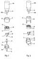
- the figures 2 , 4 and 8describe elements of a second embodiment of the invention, wherein the dispensing head 6 is not nasal but oral, and for which the dispensing member 200 may be a valve rather than a pump.
- the indicatoroperates in a very similar manner to that described above, and the difference lies in the fact that the head 6 has no insert 5, the actuating means 7 being made directly in said head 6, as visible on the figure 4 .
- the covering element 3has lateral fins enabling it to be attached to the oral distribution head 6 as visible on the figure 2 .
- the shape and the length of the actuating members 8 and / or the complementary actuating members 17 provided in the actuating means 7can be modified to adapt the device to different pump or valve strokes and / or to compensate for the overall tolerances of the system.
- the one or more actuating grooves 8could be replaced by one or more corresponding ribs cooperating with complementary complementary actuating means 17.
- the guide groove or grooves 22could be replaced by one or more corresponding ribs, cooperating with appropriate complementary guide means 23.
- the actuating members 8may also be formed on a sleeve that could be separated from the insert 5 even when using such an insert.
- This sleevecould be a part of the head 6 or a separate component.
- the maximum number of doses that the system can countmay also vary simply by adapting the number of teeth of the toothing 21 and / or the turns or fractional turns of the guide means 22 of the indication element 2.
- the shape of said guiding means 22 and / or complementary guiding means 23may be any provided that it allows radial and / or vertical guidance of the indicating element 2 with respect to the covering element 3.
- the covering element 3comprises in the drawings a single guide projection 23 cooperating with the guide groove 22, but the system could use several guide projections, or complementary guide means having different shapes from those shown.
Landscapes
- Physics & Mathematics (AREA)
- General Physics & Mathematics (AREA)
- Engineering & Computer Science (AREA)
- Theoretical Computer Science (AREA)
- Infusion, Injection, And Reservoir Apparatuses (AREA)
- Containers And Packaging Bodies Having A Special Means To Remove Contents (AREA)
Description
Translated fromFrenchLa présente invention concerne un indicateur de doses, ainsi qu'un dispositif de distribution de produit fluide comportant un tel indicateur.The present invention relates to a dose indicator, as well as to a fluid dispenser device having such an indicator.
Les indicateurs ou compteurs de doses sont bien connus pour les dispositifs de distribution de produit fluide, et notamment les distributeurs de produits pharmaceutiques, cosmétiques ou du domaine de la parfumerie. Un tel compteur de doses est décrit dans le document
La présente invention a pour but de fournir un nouvel indicateur de doses pour dispositif de distribution de produit fluide qui remplit de manière optimale toutes les exigences susmentionnées.It is an object of the present invention to provide a new dose indicator for a fluid dispensing device which optimally fulfills all of the above requirements.
En particulier, la présente invention a pour but de fournir un indicateur de doses qui permet de compter la dose en début de course d'actionnement de la pompe ou de la valve du dispositif, tout en étant de fonctionnement fiable.In particular, the object of the present invention is to provide a dose indicator which makes it possible to count the dose at the beginning of the actuating stroke of the pump or of the valve of the device, while being of reliable operation.
La présente invention à également pour but de fournir un indicateur de doses qui comporte un minimum de pièces constitutives.The present invention also aims to provide a dose indicator which comprises a minimum of component parts.
La présente invention a encore pour but de fournir un indicateur de doses qui soit simple et peu coûteux à fabriquer et à assembler.The present invention also aims to provide a dose indicator that is simple and inexpensive to manufacture and assemble.
La présente invention a également pour but de fournir un indicateur de doses qui permet de compter un grand nombre de doses.The present invention also aims to provide a dose indicator that can count a large number of doses.
La présente invention a donc pour objet un indicateur de doses pour dispositif de distribution de produit fluide selon la revendication 1.The subject of the present invention is therefore a dose indicator for a fluid dispenser device according to
Avantageusement, ledit élément d'indication est disposé autour dudit actionneur, ladite denture étant réalisée dans la paroi périphérique interne dudit élément d'indication.Advantageously, said indication element is disposed around said actuator, said toothing being made in the inner peripheral wall of said indication element.
Avantageusement, lesdits premier et second axes sont identiques.Advantageously, said first and second axes are identical.
Avantageusement, un élément de recouvrement, solidaire dudit corps, est disposé autour dudit élément d'indication, ledit élément de recouvrement comportant une fenêtre pour visualiser lesdits moyens d'indication dudit élément d'indication.Advantageously, a covering element, integral with said body, is arranged around said indicating element, said covering element comprising a window for displaying said means for indicating said indication element.
Avantageusement, l'un parmi l'élément d'indication et l'élément de recouvrement comporte des moyens de guidage coopérant avec des moyens de guidage complémentaires prévus sur l'autre élément.Advantageously, one of the indication element and the covering element comprises guiding means cooperating with complementary guiding means provided on the other element.
Avantageusement, lesdits moyens de guidage comportent au moins une rainure de guidage et lesdits moyens de guidage complémentaires comportent au moins une projection de guidage.Advantageously, said guide means comprise at least one guide groove and said complementary guide means comprise at least one guide projection.
Avantageusement, ladite rainure de guidage, qui peut notamment être hélicoïdale, fait plusieurs tours autour dudit élément d'indication, respectivement autour dudit élément de recouvrement, permettant à l'indicateur de compter un nombre de doses supérieur au nombre de dents prévues dans la denture de l'élément d'indication.Advantageously, said guide groove, which may in particular be helical, makes several turns around said indication element, respectively around said cover element, allowing the indicator to count a number of doses greater than the number of teeth provided in the toothing. of the indication element.
Avantageusement, l'un parmi l'actionneur et les moyens d'actionnement comporte au moins un organe d'actionnement au moins partiellement oblique par rapport à la direction de déplacement translatif desdits moyens d'actionnement, ledit au moins un organe d'actionnement coopérant avec au moins un organe d'actionnement complémentaire prévu sur l'autre parmi l'actionneur et les moyens d'actionnement, de sorte qu'une translation des moyens d'actionnement est transformée en rotation dudit actionneur.Advantageously, one of the actuator and the actuating means comprises at least one actuating member at least partially oblique with respect to the direction of translational movement of said actuating means, said at least one cooperating actuating member with at least one additional actuating member provided on the other of the actuator and the actuating means, so that a translation of the actuating means is converted into rotation of said actuator.
Avantageusement, ledit au moins un organe d'actionnement est une rainure d'actionnement et ledit au moins un organe d'actionnement complémentaire est une projection d'actionnement.Advantageously, said at least one actuating member is an actuating groove and said at least one complementary actuating member is an actuating projection.
Avantageusement, lesdits moyens d'entraînement de l'actionneur comportent une patte flexible supportant une projection d'entraînement coopérant avec les dents de la denture de l'élément d'indication.Advantageously, said drive means of the actuator comprise a flexible tab supporting a driving projection cooperating with the teeth of the toothing of the indication element.
Avantageusement, ladite patte flexible comporte une première partie de patte flexible et une seconde partie de patte flexible, la première partie de patte flexible supportant la projection d'entraînement et la seconde partie de patte flexible reliant ladite première patte flexible audit actionneur.Advantageously, said flexible tab comprises a first flexible tab portion and a second flexible tab portion, the first flexible tab portion supporting the drive projection and the second flexible tab portion connecting said first flexible tab to said actuator.
Avantageusement, pour assurer un comptage à chaque actionnement et compenser les tolérances de fabrication, l'angle de rotation de l'actionneur est supérieur à l'angle défini par une dent de la denture de l'élément d'indication, le corps comportant des moyens de butée pour bloquer la rotation de l'élément d'indication après rotation sur une dent de la denture, la rotation supplémentaire de l'actionneur étant compensée par une flexion de la seconde partie de patte flexible des moyens d'entraînement.Advantageously, to ensure a counting at each actuation and to compensate for manufacturing tolerances, the angle of rotation of the actuator is greater than the angle defined by a tooth of the toothing of the indicating element, the body comprising stop means for blocking the rotation of the indicating member after rotation on a tooth of the toothing, the additional rotation of the actuator being compensated by a bending of the second flexible tab portion of the drive means.
Avantageusement, ledit corps comporte une partie de paroi au moins partiellement cylindrique disposée entre ledit actionneur et ledit élément d'indication, ladite partie de paroi comportant une découpe formant un passage pour les moyens d'entraînement de l'actionneur vers la denture de l'élément d'indication.Advantageously, said body comprises an at least partially cylindrical wall portion disposed between said actuator and said element. indicating, said wall portion having a cutout forming a passage for the driving means of the actuator towards the toothing of the indicating element.
Avantageusement, un bord de ladite découpe forme lesdits moyens de butée.Advantageously, an edge of said cutout forms said abutment means.
Avantageusement, ledit corps comporte des moyens anti-retour pour l'élément d'indication, empêchant celui-ci de tourner dans le sens inverse de celui qui lui est imparti par l'actionneur.Advantageously, said body comprises non-return means for the indication element, preventing it from rotating in the opposite direction to that which is imparted to it by the actuator.
Avantageusement, lesdits moyens anti-retour comporte une patte flexible comportant une projection anti-retour coopérant avec ladite denture.Advantageously, said non-return means comprises a flexible tab comprising a non-return projection cooperating with said toothing.
Avantageusement, des moyens élastiques sont prévus pour solliciter ledit actionneur vers sa position de repos lorsque les moyens d'actionnement reviennent vers leur position de repos.Advantageously, elastic means are provided for biasing said actuator towards its rest position when the actuating means return to their rest position.
Avantageusement, lesdits moyens élastiques comportent au moins une lame élastique solidaire dudit actionneur, ladite au moins une lame élastique étant élastiquement déformée lors de l'actionnement du dispositif.Advantageously, said resilient means comprise at least one elastic blade integral with said actuator, said at least one elastic blade being elastically deformed during actuation of the device.
La présente invention a également pour objet un dispositif de distribution de produit fluide comportant un réservoir contenant le produit fluide, un organe de distribution, tel qu'une pompe ou une valve, et une tête de distribution incorporant un orifice de distribution, ledit dispositif comportant un indicateur de doses suivant la revendication 1.The present invention also relates to a fluid dispenser device comprising a reservoir containing the fluid, a dispensing member, such as a pump or a valve, and a dispensing head incorporating a dispensing orifice, said device comprising a dose indicator according to
Avantageusement, le corps est une partie de ladite tête, lesdits moyens d'actionnement étant solidaire de ladite tête.Advantageously, the body is a part of said head, said actuating means being integral with said head.
Avantageusement, lesdits moyens d'actionnement sont formés sur un insert inséré dans ladite tête en amont dudit orifice de distribution.Advantageously, said actuating means are formed on an insert inserted into said head upstream of said dispensing orifice.
D'autres caractéristiques et avantages de la présente invention apparaîtront plus clairement au cours de la description détaillée suivante de deux modes de réalisation de celle-ci, faite en référence aux dessins joints, donnés à titre d'exemples non limitatifs, et sur lesquels :
- la
figure 1 est une vue schématique en perspective éclatée d'un dispositif de distribution de produit fluide selon un premier mode de réalisation de la présente invention ; - la
figure 2 est une vue similaire à celle de lafigure 1 montrant un second mode de réalisation de la présente invention ; - la
figure 3 est une vue schématique en perspective d'une partie du dispositif de lafigure 1 ; - la
figure 4 est une vue similaire à celle de lafigure 3 , montrant une partie du dispositif de lafigure 2 . - la
figure 5 est une vue schématique en perspective d'un actionneur selon un mode de réalisation avantageux de la présente invention ; - la
figure 6 est une vue schématique en perspective d'un élément d'indication selon un mode de réalisation avantageux de la présente invention ; - la
figure 7 est une vue schématique en perspective d'un élément de recouvrement adapté au premier mode de réalisation de l'invention représenté sur lafigure 1 ; - la
figure 8 est une vue schématique en perspective d'un élément de recouvrement adapté pour le second mode de réalisation décrit sur lafigure 2 ; - la
figure 9 est une vue schématique en perspective d'une partie de l'indicateur selon un mode de réalisation avantageux de la présente invention ; - la
figure 10 est une vue schématique en perspective partiellement découpée d'un dispositif de distribution incorporant un indicateur selon le premier mode de réalisation représenté sur lafigure 1 ; et - la
figure 11 est une vue similaire à celle de lafigure 10 prise selon un autre angle de vue.
- the
figure 1 is a schematic perspective exploded view of a fluid dispenser device according to a first embodiment of the present invention; - the
figure 2 is a view similar to that of thefigure 1 showing a second embodiment of the present invention; - the
figure 3 is a schematic view in perspective of a part of the device of thefigure 1 ; - the
figure 4 is a view similar to that of thefigure 3 , showing part of the device of thefigure 2 . - the
figure 5 is a schematic perspective view of an actuator according to an advantageous embodiment of the present invention; - the
figure 6 is a schematic perspective view of an indication element according to an advantageous embodiment of the present invention; - the
figure 7 is a schematic perspective view of a covering element adapted to the first embodiment of the invention shown in FIG.figure 1 ; - the
figure 8 is a schematic perspective view of a covering element adapted for the second embodiment described on thefigure 2 ; - the
figure 9 is a schematic perspective view of a portion of the indicator according to an advantageous embodiment of the present invention; - the
figure 10 is a schematic perspective view partially cut away of a distribution device incorporating an indicator according to the first embodiment shown in thefigure 1 ; and - the
figure 11 is a view similar to that of thefigure 10 taken from another angle of view.
L'invention va être décrite ci-après en référence à deux modes de réalisation, représentée respectivement sur les
En se référant plus particulièrement à la
L'élément d'indication 2 comporte une denture 21 qui coopère avec des moyens d'entraînement 14, 15 de l'actionneur 1. Avantageusement, comme visible sur les
Le principe de fonctionnement de l'indicateur de la présente invention est le suivant : l'actionneur 1 coopère avec des moyens d'actionnement 7 qui sont solidaires du corps 4 et qui sont déplaçables en translation à chaque actionnement du dispositif de distribution. Ce déplacement en translation des moyens d'actionnement 7 est transformé en rotation dudit actionneur, de sorte que chaque actionnement du dispositif provoque une rotation de l'élément d'indication 2 par l'intermédiaire de l'actionneur 1, pour compter une dose.The principle of operation of the indicator of the present invention is as follows: the
De préférence, soit l'actionneur 1, soit les moyens d'actionnement 7 comportent des organes d'actionnement 8, réalisés avantageusement par au moins une rainure d'actionnement 8. L'autre de ces deux éléments comporte des organes d'actionnement complémentaires 17, réalisés avantageusement par au moins une projection d'actionnement 17 coopérant avec ladite au moins une rainure d'actionnement 8. Dans les exemples représentés sur les figures, ce sont les moyens d'actionnement 7 qui comportent deux rainures 8 diamétralement opposées, et l'actionneur 1 comporte deux projections 17 diamétralement opposées coulissant dans lesdites rainures 8. Comme visible notamment sur la
Avantageusement, il est prévu un élément de recouvrement 3 disposé autour de l'élément d'indication 2. Cet élément de recouvrement 3 est de préférence solidaire du corps 4 et comporte une fenêtre 24 permettant de visualiser les moyens d'indication 25 de l'élément d'indication 2. Comme visible notamment sur la
L'actionneur 1 comporte avantageusement un manchon 16 qui entoure les moyens d'actionnement 7, comme visible sur les
Après actionnement, lorsque le système revient vers sa position de repos, la projection d'entraînement 14 peut glisser contre les dents de la denture 21 grâce à la flexion de la première partie de la patte flexible 15a. Comme expliqué précédemment, il n'y a aucun risque que l'élément d'indication ne soit entraîné en rotation par cette opération, grâce aux moyens anti-retour prévus sur le corps 4.After actuation, when the system returns to its rest position, the
Avantageusement, on prévoit des moyens élastiques 18 pour solliciter l'actionneur 1 vers sa position de repos lorsque les moyens d'actionnement 7 reviennent vers la position de repos. Plus précisément, ces moyens élastiques 18 sollicitent l'actionneur 1 en butée contre la bague de fixation 19, et évite donc que l'actionneur 1 ne soit déplacé axialement avec les moyens d'actionnement 7 lorsque ceux-ci remontent vers leur position de repos, par exemple par frottement. Ces moyens élastiques 18 peuvent être réalisés de manière quelconque, mais avantageusement les exemples représentés montrent deux lames élastiques 18 solidaires de l'actionneur 1 qui sont élastiquement déformées lors de l'actionnement du dispositif. Bien entendu, des moyens élastiques séparés de l'actionneur pourraient être envisagés.Advantageously, resilient means 18 are provided for biasing the
Les
Bien que la présente invention ait été décrite en référence à deux modes de réalisation, il est clair que diverses modifications sont envisageables. Ainsi par exemple la forme et la longueur des organes d'actionnement 8 et/ou des organes d'actionnement complémentaires 17 prévus dans les moyens d'actionnement 7 peuvent être modifiés pour adapter le dispositif à des courses de pompe ou de valve différentes et/ou pour compenser les tolérances globales du système. La ou les rainures d'actionnement 8 pourraient être remplacées par une ou des nervures correspondantes, coopérant avec des organes d'actionnement complémentaires 17 appropriés. De même, la ou les rainures de guidage 22 pourraient être remplacées par une ou des nervures correspondantes, coopérant avec des moyens de guidage complémentaires 23 appropriés. Les organes d'actionnement 8 peuvent également être formés sur un manchon qui pourrait être séparé de l'insert 5 même en cas d'utilisation d'un tel insert. Ce manchon pourrait être une partie de la tête 6 ou un composant séparé. Le nombre maximal de doses que le système peut compter peut également varier simplement en adaptant le nombre de dents de la denture 21 et/ou les tours ou fractions de tours des moyens de guidage 22 de l'élément d'indication 2. La forme desdits moyens de guidage 22 et/ou des moyens de guidage complémentaires 23 peut être quelconque à condition qu'elle permette un guidage radial et/ou vertical de l'élément d'indication 2 par rapport à l'élément de recouvrement 3. De même, l'élément de recouvrement 3 comporte sur les dessins une seule projection de guidage 23 coopérant avec la rainure de guidage 22, mais le système pourrait utiliser plusieurs projections de guidage, ou des moyens de guidage complémentaires ayant des formes différentes de celles représentées.Although the present invention has been described with reference to two embodiments, it is clear that various modifications are possible. Thus, for example, the shape and the length of the
D'autres modifications sont également envisageables pour l'homme du métier sans sortir du cadre de la présente invention tel que défini par les revendications annexées.Other modifications are also conceivable for those skilled in the art without departing from the scope of the present invention as defined by the appended claims.
Claims (21)
- A dose indicator for a fluid dispenser device, said indicator comprising:• a body (4);• an actuator (1) that is mounted to turn relative to said body (4) about a first axis, and including drive means (14, 15); and• a cylindrical indicator element (2) that is mounted to turn relative to said body (4) about a second axis and including a set of teeth (21) that co-operate with said drive means (14, 15) of said actuator (1) so as to turn each time the dispenser device is actuated, said indicator element (2) further including numeric and/or symbolic indicator means (25) so as to indicate to the user the number of doses that have been dispensed or that remain to be dispensed from said dispenser device;• said actuator (1) co-operating with actuator means (7) secured to said body (4), said actuator means (7) being displaced in translation each time the dispenser device is actuated, and co-operating with said actuator (1) so as to transform the translation of said actuator means (7) into said actuator (1) turning, said indicator beingcharacterized in that• one amongst the actuator (1) and the actuator means (7) includes at least one actuator member (8) that is partially oblique relative to the direction of displacement in translation of said actuator means (7), said at least one actuator member (8) co-operating with at least one complementary actuator member (17) provided on the other one amongst the actuator (1) and the actuator means (7), so that a displacement in translation of the actuator means (7) is transformed into said actuator (1) turning,• andin that said actuator member (8) comprises an oblique portion that enables the dose to be counted, and a rectilinear portion disposed after said oblique portion in the actuation direction of said actuator means (7), said rectilinear portion enabling the actuation stroke of the device to be continued after the dose has been counted.
- An indicator according to claim 1, in which said indicator element (2) is disposed around said actuator (1), said set of teeth (21) being formed on the inside peripheral wall of said indicator element (2).
- An indicator according to claim 1 or claim 2, in which said first and second axes are identical.
- An indicator according to any preceding claim, in which a cover element (3), secured to said body (4), is disposed around said indicator element (2), said cover element (3) including a window (24) in order to see said indicator means (25) of said indicator element (2).
- An indicator according to claim 4, in which one amongst the indicator element (2) and the cover element (3) includes guide means (22) that co-operate with complementary guide means (23) provided on the other element (3, 2).
- An indicator according to claim 5, in which said guide means (22) comprise at least one guide groove (22), and said complementary guide means comprise at least one guide projection (23).
- An indicator according to claim 6, in which said guide groove (22), which may in particular be helical, winds around said indicator element (2) in a plurality of turns, or alternatively around said cover element (3), enabling the indicator to count a number of doses that is greater than the number of teeth provided in the set of teeth (21) of the indicator element (2).
- An indicator according to any preceding claim, in which said oblique portion is provided at the start of the actuation stroke of the device.
- An indicator according to any preceding claim, in which said at least one actuator member (8) is an actuator groove (8), and said at least one complementary actuator member (17) is an actuator projection (17).
- An indicator according to any preceding claim, in which said drive means (14, 15) of the actuator comprise a flexible tab (15) supporting a drive projection (14) that co-operates with the teeth of the set of teeth (21) of the indicator element (2).
- An indicator according to claim 10, in which said flexible tab (15) comprises a first flexible tab portion (15a), and a second flexible tab portion (15b), the first flexible tab portion (15a) supporting the drive projection (14), and the second flexible tab portion (15b) connecting said first flexible tab (15a) to said actuator (1).
- An indicator according to claim 11, in which, in order to ensure a count at each actuation, and in order to compensate for manufacturing tolerances, the angle through which the actuator (1) turns is greater than the angle defined by a tooth in the set of teeth (21) of the indicator element (2), the body (4) including abutment means (13) to prevent the indicator element (2) from turning through more than one tooth in the set of teeth (21), the additional amount through which the actuator (1) turns being compensated by the second flexible-tab portion (15b) of the drive means (14, 15) flexing.
- An indicator according to any preceding claim, in which said body (4) includes a wall portion (4) that is cylindrical, at least in part, and that is disposed between said actuator (1) and said indicator element (2), said wall portion having a cut-out (40) forming a passage for passing the drive means (14, 15) of the actuator (1) to the set of teeth (21) of the indicator element (2).
- An indicator according to claim 12 and claim 13, in which an edge (13) of said cut-out (40) forms said abutment means (13).
- An indicator according to claim 12 or claim 13, in which said body (4) includes anti-return means (11, 12) for the indicator element (2), said anti-return means preventing said element from turning in the direction opposite to the direction imparted thereto by the actuator (1).
- An indicator according to claim 15, in which said anti-return means (11, 12) comprises a flexible tab (11) including an anti-return projection (12) that co-operates with said set of teeth (21).
- An indicator according to any preceding claim, in which resilient means (18) are provided so as to urge said actuator (1) towards its rest position while the actuator means (7) are returning to their rest position.
- An indicator according to claim 17, in which said resilient means (18) comprise at least one resilient blade (18) that is secured to said actuator (1), said at least one resilient blade (18) being elastically deformed while the device is being actuated.
- A fluid dispenser device comprising: a reservoir (100) containing the fluid; a dispenser member (200), such as a pump or a valve; and a dispenser head (6) incorporating a dispenser orifice, said device beingcharacterized in that it further comprises a dose indicator according to any preceding claim.
- A device according to claim 19, in which the body (4) is a portion of said head (6), said actuator means (7) being secured to said head (6).
- A device according to claim 19 or claim 20, in which said actuator means (7) are formed on an insert (5) that is inserted into said head (6) upstream from said dispenser orifice.
Applications Claiming Priority (2)
| Application Number | Priority Date | Filing Date | Title |
|---|---|---|---|
| FR0309886AFR2858867B1 (en) | 2003-08-12 | 2003-08-12 | DOSING INDICATOR FOR FLUID PRODUCT DISPENSING DEVICE |
| PCT/FR2004/002007WO2005020138A1 (en) | 2003-08-12 | 2004-07-27 | Indicator of doses for a liquid product distribution device |
Publications (2)
| Publication Number | Publication Date |
|---|---|
| EP1661070A1 EP1661070A1 (en) | 2006-05-31 |
| EP1661070B1true EP1661070B1 (en) | 2012-09-19 |
Family
ID=34112742
Family Applications (1)
| Application Number | Title | Priority Date | Filing Date |
|---|---|---|---|
| EP04767789AExpired - LifetimeEP1661070B1 (en) | 2003-08-12 | 2004-07-27 | Indicator of doses for a liquid product distribution device |
Country Status (6)
| Country | Link |
|---|---|
| US (1) | US7510100B2 (en) |
| EP (1) | EP1661070B1 (en) |
| JP (1) | JP4676433B2 (en) |
| CN (1) | CN100557629C (en) |
| FR (1) | FR2858867B1 (en) |
| WO (1) | WO2005020138A1 (en) |
Families Citing this family (13)
| Publication number | Priority date | Publication date | Assignee | Title |
|---|---|---|---|---|
| DE102005033398A1 (en)* | 2004-11-10 | 2006-05-11 | Alfred Von Schuckmann | Inhale device |
| GB0425518D0 (en) | 2004-11-19 | 2004-12-22 | Clinical Designs Ltd | Substance source |
| GB0428204D0 (en) | 2004-12-23 | 2005-01-26 | Clinical Designs Ltd | Medicament container |
| GB0518400D0 (en) | 2005-09-09 | 2005-10-19 | Clinical Designs Ltd | Dispenser |
| GB0706999D0 (en)* | 2007-04-11 | 2007-05-16 | Ivax Pharmaceuticals Ireland | Metered-dose inhaler |
| DE102007045438B4 (en)* | 2007-09-22 | 2016-09-01 | Boehringer Ingelheim International Gmbh | Inhale device |
| DE102008044770A1 (en)* | 2008-08-28 | 2010-03-25 | Boehringer Ingelheim Pharma Gmbh & Co. Kg | Drive unit for dose counter |
| GB0904040D0 (en) | 2009-03-10 | 2009-04-22 | Euro Celtique Sa | Counter |
| GB0904059D0 (en) | 2009-03-10 | 2009-04-22 | Euro Celtique Sa | Counter |
| CN104203319B (en)* | 2012-01-23 | 2017-03-08 | 赛诺菲股份有限公司 | Dose counter mechanism and suction apparatus for suction apparatus |
| DE102014114462A1 (en)* | 2013-10-15 | 2015-04-16 | Alfred Von Schuckmann | Counter and handset with counter |
| FR3077495B1 (en)* | 2018-02-07 | 2023-04-14 | Aptar France Sas | FLUID PRODUCT DISTRIBUTION SET. |
| CN112049844B (en)* | 2020-09-10 | 2025-04-08 | 宁波华德汽车零部件有限公司 | Fastening device with tolerance compensation function and fastening method thereof |
Family Cites Families (18)
| Publication number | Priority date | Publication date | Assignee | Title |
|---|---|---|---|---|
| US2875950A (en)* | 1952-09-16 | 1959-03-03 | Mast Dev Company Inc | Dot counters |
| UA26230A (en)* | 1990-03-02 | 1999-07-19 | Глексо Груп Лімітед | SHARED USER INHALATOR WITH TREATMENT UNIT AND TREATMENT UNIT |
| IT1243820B (en)* | 1990-10-09 | 1994-06-28 | Elettro Plastica Spa | CONTADOSI DEVICE FOR DISPENSING DOSES OF FLUID PRODUCT, PARTICULARLY FOR PHARMACEUTICAL USE |
| NZ259241A (en)* | 1992-12-18 | 1996-12-20 | Schering Corp | Inhaler including a counter ring, a nozzle to break powder agglomerates and spring-biased, bi-directionally rotatable metering plate and powder house |
| FR2721106B1 (en)* | 1994-06-10 | 1996-09-13 | Step | Dose counter for inhalers. |
| AU710027B2 (en)* | 1994-09-16 | 1999-09-09 | Laboratoire Glaxo Wellcome | Inhalation device |
| FR2750780B1 (en)* | 1996-07-05 | 1998-10-30 | Valois | DOSER COUNTER |
| GB9700226D0 (en)* | 1997-01-08 | 1997-02-26 | Glaxo Group Ltd | Inhalation device |
| US6142339A (en)* | 1998-01-16 | 2000-11-07 | 1263152 Ontario Inc. | Aerosol dispensing device |
| US6082358A (en)* | 1998-05-05 | 2000-07-04 | 1263152 Ontario Inc. | Indicating device for aerosol container |
| IT1312426B1 (en)* | 1999-06-30 | 2002-04-17 | Microspray Delta Spa | DISPENSER OF DOSES OF A LIQUID, WITH A DEVICE FOR COUNTING A HIGH NUMBER OF DOSES DISPENSED |
| US6615827B2 (en)* | 1999-09-08 | 2003-09-09 | Sapphire Designs, Inc. | Inhalation counter device |
| US6516799B1 (en)* | 1999-09-08 | 2003-02-11 | Sapphire Design, Inc. | Inhalation counter device |
| DE10061723C2 (en)* | 2000-12-12 | 2003-01-16 | Eckert Rosemarie | Counter for counting metered deliveries of liquid, pasty or solid products as well as device for metered dispensing of such products |
| SE0100034D0 (en)* | 2001-01-04 | 2001-01-04 | Astrazeneca Ab | A delivery device |
| GB2372543B (en)* | 2001-02-23 | 2003-08-20 | Bespak Plc | Dosage counting devices |
| AU2002325239A1 (en)* | 2002-06-12 | 2003-12-31 | Steag Mikcroparts Gmbh | Counter for counting metered doses of liquid, pasty, or solid products and device for the metered dispensing of such products |
| DE102005033398A1 (en)* | 2004-11-10 | 2006-05-11 | Alfred Von Schuckmann | Inhale device |
- 2003
- 2003-08-12FRFR0309886Apatent/FR2858867B1/ennot_activeExpired - Lifetime
- 2004
- 2004-07-27JPJP2006523028Apatent/JP4676433B2/ennot_activeExpired - Fee Related
- 2004-07-27CNCN200480022963.6Apatent/CN100557629C/ennot_activeExpired - Fee Related
- 2004-07-27WOPCT/FR2004/002007patent/WO2005020138A1/enactiveSearch and Examination
- 2004-07-27USUS10/567,353patent/US7510100B2/enactiveActive
- 2004-07-27EPEP04767789Apatent/EP1661070B1/ennot_activeExpired - Lifetime
Also Published As
| Publication number | Publication date |
|---|---|
| EP1661070A1 (en) | 2006-05-31 |
| CN100557629C (en) | 2009-11-04 |
| FR2858867B1 (en) | 2005-11-04 |
| FR2858867A1 (en) | 2005-02-18 |
| JP4676433B2 (en) | 2011-04-27 |
| JP2007502457A (en) | 2007-02-08 |
| WO2005020138A1 (en) | 2005-03-03 |
| CN1839400A (en) | 2006-09-27 |
| US7510100B2 (en) | 2009-03-31 |
| US20070194041A1 (en) | 2007-08-23 |
Similar Documents
| Publication | Publication Date | Title |
|---|---|---|
| EP1438095B1 (en) | Dosimeter for fluid product dispenser | |
| EP1661070B1 (en) | Indicator of doses for a liquid product distribution device | |
| EP1590765B1 (en) | Dosage indicator for a device dispensing a fluid product | |
| EP2021987B1 (en) | Dose indicator for a fluid product dispensing device | |
| EP1756760A1 (en) | Indicator for a device for dispensing a liquid or powdery product | |
| EP1649415B1 (en) | Improved dose indicator for fluid product dispensing device | |
| EP1745421B1 (en) | Indicator for a fluid or powder dispenser device | |
| EP1660845B1 (en) | Improved dose indicator for fluid product dispensing device | |
| WO2010125291A1 (en) | Meter for a device for dispensing a fluid or powder product | |
| WO2010125288A1 (en) | Meter for fluid or powdery product dispensing device | |
| EP1525437B1 (en) | Dose indicator for fluid product dispensing device | |
| FR2684880A1 (en) | MECHANICAL DEVICE WITH DISPLAY OF A VISUAL INDICATION, SUCH AS A GRADUATION. | |
| EP2380117B1 (en) | Counter for fluid or powder dispenser | |
| EP2406757B1 (en) | Meter for a device for dispensing a fluid or powder product | |
| WO2009147350A2 (en) | Device for dispensing a fluid product | |
| FR2873808A1 (en) | Dose indicator for liquid/powdery product dispensing device, has tabs co-operating with counting unit teeth to rotate unit in direction when actuating unit is displaced from idle to actuating position and from actuating to idle position | |
| WO2023067283A1 (en) | Dose counter for a device for dispensing a fluid or powder product | |
| FR2854973A1 (en) | Dose meter for liquid product dispenser, includes flexible metering tape which is fed from feeding ring to receiving ring each time the meter is activated, and carrying figures or symbols for indicating amount of dispensed product |
Legal Events
| Date | Code | Title | Description |
|---|---|---|---|
| PUAI | Public reference made under article 153(3) epc to a published international application that has entered the european phase | Free format text:ORIGINAL CODE: 0009012 | |
| 17P | Request for examination filed | Effective date:20060303 | |
| AK | Designated contracting states | Kind code of ref document:A1 Designated state(s):DE FR GB IT | |
| DAX | Request for extension of the european patent (deleted) | ||
| RBV | Designated contracting states (corrected) | Designated state(s):DE FR GB IT | |
| GRAP | Despatch of communication of intention to grant a patent | Free format text:ORIGINAL CODE: EPIDOSNIGR1 | |
| GRAS | Grant fee paid | Free format text:ORIGINAL CODE: EPIDOSNIGR3 | |
| GRAA | (expected) grant | Free format text:ORIGINAL CODE: 0009210 | |
| RAP1 | Party data changed (applicant data changed or rights of an application transferred) | Owner name:APTAR FRANCE SAS | |
| AK | Designated contracting states | Kind code of ref document:B1 Designated state(s):DE FR GB IT | |
| REG | Reference to a national code | Ref country code:GB Ref legal event code:FG4D Free format text:NOT ENGLISH | |
| REG | Reference to a national code | Ref country code:DE Ref legal event code:R096 Ref document number:602004039387 Country of ref document:DE Effective date:20121115 | |
| PLBE | No opposition filed within time limit | Free format text:ORIGINAL CODE: 0009261 | |
| STAA | Information on the status of an ep patent application or granted ep patent | Free format text:STATUS: NO OPPOSITION FILED WITHIN TIME LIMIT | |
| 26N | No opposition filed | Effective date:20130620 | |
| PG25 | Lapsed in a contracting state [announced via postgrant information from national office to epo] | Ref country code:IT Free format text:LAPSE BECAUSE OF FAILURE TO SUBMIT A TRANSLATION OF THE DESCRIPTION OR TO PAY THE FEE WITHIN THE PRESCRIBED TIME-LIMIT Effective date:20120919 | |
| REG | Reference to a national code | Ref country code:DE Ref legal event code:R097 Ref document number:602004039387 Country of ref document:DE Effective date:20130620 | |
| REG | Reference to a national code | Ref country code:DE Ref legal event code:R082 Ref document number:602004039387 Country of ref document:DE Representative=s name:STAUDT IP LAW, DE | |
| REG | Reference to a national code | Ref country code:FR Ref legal event code:PLFP Year of fee payment:12 | |
| REG | Reference to a national code | Ref country code:FR Ref legal event code:PLFP Year of fee payment:13 | |
| REG | Reference to a national code | Ref country code:FR Ref legal event code:PLFP Year of fee payment:14 | |
| REG | Reference to a national code | Ref country code:FR Ref legal event code:PLFP Year of fee payment:15 | |
| PGFP | Annual fee paid to national office [announced via postgrant information from national office to epo] | Ref country code:GB Payment date:20220718 Year of fee payment:19 Ref country code:DE Payment date:20220624 Year of fee payment:19 | |
| P01 | Opt-out of the competence of the unified patent court (upc) registered | Effective date:20230526 | |
| PGFP | Annual fee paid to national office [announced via postgrant information from national office to epo] | Ref country code:FR Payment date:20230728 Year of fee payment:20 | |
| REG | Reference to a national code | Ref country code:DE Ref legal event code:R082 Ref document number:602004039387 Country of ref document:DE Representative=s name:SONNENBERG HARRISON PARTNERSCHAFT MBB PATENT- , DE | |
| REG | Reference to a national code | Ref country code:DE Ref legal event code:R119 Ref document number:602004039387 Country of ref document:DE | |
| GBPC | Gb: european patent ceased through non-payment of renewal fee | Effective date:20230727 | |
| PG25 | Lapsed in a contracting state [announced via postgrant information from national office to epo] | Ref country code:DE Free format text:LAPSE BECAUSE OF NON-PAYMENT OF DUE FEES Effective date:20240201 Ref country code:GB Free format text:LAPSE BECAUSE OF NON-PAYMENT OF DUE FEES Effective date:20230727 |