EP1660213B1 - Filter unit for filtering particles contained in exhaust gas of an internal combusting engine - Google Patents
Filter unit for filtering particles contained in exhaust gas of an internal combusting engineDownload PDFInfo
- Publication number
- EP1660213B1 EP1660213B1EP04767682AEP04767682AEP1660213B1EP 1660213 B1EP1660213 B1EP 1660213B1EP 04767682 AEP04767682 AEP 04767682AEP 04767682 AEP04767682 AEP 04767682AEP 1660213 B1EP1660213 B1EP 1660213B1
- Authority
- EP
- European Patent Office
- Prior art keywords
- channels
- filtration unit
- unit according
- output channels
- filtration
- Prior art date
- Legal status (The legal status is an assumption and is not a legal conclusion. Google has not performed a legal analysis and makes no representation as to the accuracy of the status listed.)
- Expired - Lifetime
Links
Images


Classifications
- B—PERFORMING OPERATIONS; TRANSPORTING
- B01—PHYSICAL OR CHEMICAL PROCESSES OR APPARATUS IN GENERAL
- B01D—SEPARATION
- B01D46/00—Filters or filtering processes specially modified for separating dispersed particles from gases or vapours
- B01D46/24—Particle separators, e.g. dust precipitators, using rigid hollow filter bodies
- B01D46/2403—Particle separators, e.g. dust precipitators, using rigid hollow filter bodies characterised by the physical shape or structure of the filtering element
- B01D46/2418—Honeycomb filters
- B01D46/2451—Honeycomb filters characterized by the geometrical structure, shape, pattern or configuration or parameters related to the geometry of the structure
- B01D46/247—Honeycomb filters characterized by the geometrical structure, shape, pattern or configuration or parameters related to the geometry of the structure of the cells
- B—PERFORMING OPERATIONS; TRANSPORTING
- B01—PHYSICAL OR CHEMICAL PROCESSES OR APPARATUS IN GENERAL
- B01D—SEPARATION
- B01D46/00—Filters or filtering processes specially modified for separating dispersed particles from gases or vapours
- B01D46/24—Particle separators, e.g. dust precipitators, using rigid hollow filter bodies
- B01D46/2403—Particle separators, e.g. dust precipitators, using rigid hollow filter bodies characterised by the physical shape or structure of the filtering element
- B01D46/2418—Honeycomb filters
- B01D46/2451—Honeycomb filters characterized by the geometrical structure, shape, pattern or configuration or parameters related to the geometry of the structure
- B01D46/2482—Thickness, height, width, length or diameter
- B—PERFORMING OPERATIONS; TRANSPORTING
- B01—PHYSICAL OR CHEMICAL PROCESSES OR APPARATUS IN GENERAL
- B01D—SEPARATION
- B01D46/00—Filters or filtering processes specially modified for separating dispersed particles from gases or vapours
- B01D46/24—Particle separators, e.g. dust precipitators, using rigid hollow filter bodies
- B01D46/2403—Particle separators, e.g. dust precipitators, using rigid hollow filter bodies characterised by the physical shape or structure of the filtering element
- B01D46/2418—Honeycomb filters
- B01D46/2451—Honeycomb filters characterized by the geometrical structure, shape, pattern or configuration or parameters related to the geometry of the structure
- B01D46/2484—Cell density, area or aspect ratio
- B—PERFORMING OPERATIONS; TRANSPORTING
- B01—PHYSICAL OR CHEMICAL PROCESSES OR APPARATUS IN GENERAL
- B01D—SEPARATION
- B01D46/00—Filters or filtering processes specially modified for separating dispersed particles from gases or vapours
- B01D46/24—Particle separators, e.g. dust precipitators, using rigid hollow filter bodies
- B01D46/2403—Particle separators, e.g. dust precipitators, using rigid hollow filter bodies characterised by the physical shape or structure of the filtering element
- B01D46/2418—Honeycomb filters
- B01D46/2451—Honeycomb filters characterized by the geometrical structure, shape, pattern or configuration or parameters related to the geometry of the structure
- B01D46/2486—Honeycomb filters characterized by the geometrical structure, shape, pattern or configuration or parameters related to the geometry of the structure characterised by the shapes or configurations
- F—MECHANICAL ENGINEERING; LIGHTING; HEATING; WEAPONS; BLASTING
- F01—MACHINES OR ENGINES IN GENERAL; ENGINE PLANTS IN GENERAL; STEAM ENGINES
- F01N—GAS-FLOW SILENCERS OR EXHAUST APPARATUS FOR MACHINES OR ENGINES IN GENERAL; GAS-FLOW SILENCERS OR EXHAUST APPARATUS FOR INTERNAL-COMBUSTION ENGINES
- F01N3/00—Exhaust or silencing apparatus having means for purifying, rendering innocuous, or otherwise treating exhaust
- F01N3/02—Exhaust or silencing apparatus having means for purifying, rendering innocuous, or otherwise treating exhaust for cooling, or for removing solid constituents of, exhaust
- F01N3/021—Exhaust or silencing apparatus having means for purifying, rendering innocuous, or otherwise treating exhaust for cooling, or for removing solid constituents of, exhaust by means of filters
- F01N3/022—Exhaust or silencing apparatus having means for purifying, rendering innocuous, or otherwise treating exhaust for cooling, or for removing solid constituents of, exhaust by means of filters characterised by specially adapted filtering structure, e.g. honeycomb, mesh or fibrous
- F01N3/0222—Exhaust or silencing apparatus having means for purifying, rendering innocuous, or otherwise treating exhaust for cooling, or for removing solid constituents of, exhaust by means of filters characterised by specially adapted filtering structure, e.g. honeycomb, mesh or fibrous the structure being monolithic, e.g. honeycombs
- B—PERFORMING OPERATIONS; TRANSPORTING
- B01—PHYSICAL OR CHEMICAL PROCESSES OR APPARATUS IN GENERAL
- B01D—SEPARATION
- B01D46/00—Filters or filtering processes specially modified for separating dispersed particles from gases or vapours
- B01D46/24—Particle separators, e.g. dust precipitators, using rigid hollow filter bodies
- B01D46/2403—Particle separators, e.g. dust precipitators, using rigid hollow filter bodies characterised by the physical shape or structure of the filtering element
- B01D46/2418—Honeycomb filters
- B01D46/2498—The honeycomb filter being defined by mathematical relationships
- F—MECHANICAL ENGINEERING; LIGHTING; HEATING; WEAPONS; BLASTING
- F01—MACHINES OR ENGINES IN GENERAL; ENGINE PLANTS IN GENERAL; STEAM ENGINES
- F01N—GAS-FLOW SILENCERS OR EXHAUST APPARATUS FOR MACHINES OR ENGINES IN GENERAL; GAS-FLOW SILENCERS OR EXHAUST APPARATUS FOR INTERNAL-COMBUSTION ENGINES
- F01N2330/00—Structure of catalyst support or particle filter
- F01N2330/06—Ceramic, e.g. monoliths
- F—MECHANICAL ENGINEERING; LIGHTING; HEATING; WEAPONS; BLASTING
- F01—MACHINES OR ENGINES IN GENERAL; ENGINE PLANTS IN GENERAL; STEAM ENGINES
- F01N—GAS-FLOW SILENCERS OR EXHAUST APPARATUS FOR MACHINES OR ENGINES IN GENERAL; GAS-FLOW SILENCERS OR EXHAUST APPARATUS FOR INTERNAL-COMBUSTION ENGINES
- F01N2330/00—Structure of catalyst support or particle filter
- F01N2330/30—Honeycomb supports characterised by their structural details
- F01N2330/48—Honeycomb supports characterised by their structural details characterised by the number of flow passages, e.g. cell density
- Y—GENERAL TAGGING OF NEW TECHNOLOGICAL DEVELOPMENTS; GENERAL TAGGING OF CROSS-SECTIONAL TECHNOLOGIES SPANNING OVER SEVERAL SECTIONS OF THE IPC; TECHNICAL SUBJECTS COVERED BY FORMER USPC CROSS-REFERENCE ART COLLECTIONS [XRACs] AND DIGESTS
- Y02—TECHNOLOGIES OR APPLICATIONS FOR MITIGATION OR ADAPTATION AGAINST CLIMATE CHANGE
- Y02T—CLIMATE CHANGE MITIGATION TECHNOLOGIES RELATED TO TRANSPORTATION
- Y02T10/00—Road transport of goods or passengers
- Y02T10/10—Internal combustion engine [ICE] based vehicles
- Y02T10/12—Improving ICE efficiencies
- Y—GENERAL TAGGING OF NEW TECHNOLOGICAL DEVELOPMENTS; GENERAL TAGGING OF CROSS-SECTIONAL TECHNOLOGIES SPANNING OVER SEVERAL SECTIONS OF THE IPC; TECHNICAL SUBJECTS COVERED BY FORMER USPC CROSS-REFERENCE ART COLLECTIONS [XRACs] AND DIGESTS
- Y10—TECHNICAL SUBJECTS COVERED BY FORMER USPC
- Y10S—TECHNICAL SUBJECTS COVERED BY FORMER USPC CROSS-REFERENCE ART COLLECTIONS [XRACs] AND DIGESTS
- Y10S55/00—Gas separation
- Y10S55/05—Methods of making filter
- Y—GENERAL TAGGING OF NEW TECHNOLOGICAL DEVELOPMENTS; GENERAL TAGGING OF CROSS-SECTIONAL TECHNOLOGIES SPANNING OVER SEVERAL SECTIONS OF THE IPC; TECHNICAL SUBJECTS COVERED BY FORMER USPC CROSS-REFERENCE ART COLLECTIONS [XRACs] AND DIGESTS
- Y10—TECHNICAL SUBJECTS COVERED BY FORMER USPC
- Y10S—TECHNICAL SUBJECTS COVERED BY FORMER USPC CROSS-REFERENCE ART COLLECTIONS [XRACs] AND DIGESTS
- Y10S55/00—Gas separation
- Y10S55/10—Residue burned
- Y—GENERAL TAGGING OF NEW TECHNOLOGICAL DEVELOPMENTS; GENERAL TAGGING OF CROSS-SECTIONAL TECHNOLOGIES SPANNING OVER SEVERAL SECTIONS OF THE IPC; TECHNICAL SUBJECTS COVERED BY FORMER USPC CROSS-REFERENCE ART COLLECTIONS [XRACs] AND DIGESTS
- Y10—TECHNICAL SUBJECTS COVERED BY FORMER USPC
- Y10S—TECHNICAL SUBJECTS COVERED BY FORMER USPC CROSS-REFERENCE ART COLLECTIONS [XRACs] AND DIGESTS
- Y10S55/00—Gas separation
- Y10S55/30—Exhaust treatment
- Y—GENERAL TAGGING OF NEW TECHNOLOGICAL DEVELOPMENTS; GENERAL TAGGING OF CROSS-SECTIONAL TECHNOLOGIES SPANNING OVER SEVERAL SECTIONS OF THE IPC; TECHNICAL SUBJECTS COVERED BY FORMER USPC CROSS-REFERENCE ART COLLECTIONS [XRACs] AND DIGESTS
- Y10—TECHNICAL SUBJECTS COVERED BY FORMER USPC
- Y10T—TECHNICAL SUBJECTS COVERED BY FORMER US CLASSIFICATION
- Y10T428/00—Stock material or miscellaneous articles
- Y10T428/24—Structurally defined web or sheet [e.g., overall dimension, etc.]
- Y10T428/24149—Honeycomb-like
Definitions
- the inventionrelates to a filter block for the filtration of particles contained in the exhaust gases of internal combustion engines, in particular of the diesel type, and to a filter body comprising at least one filter block according to the invention.
- Porous honeycomb structuresare used as filter bodies for the filtration of particles emitted by diesel vehicles.
- these filtering bodiesare ceramic (cordierite, silicon carbide, etc.). They can be monolithic or consist of different blocks. In the latter case, the blocks are assembled together by bonding with a ceramic cement. Everything is then machined to take the desired section, circular or elliptical in general.
- the filter bodyhas a plurality of channels. It is inserted in a metal enclosure. Each channel is closed at one or other of its ends. There are thus input channels and output channels. The exhaust gases are thus forced to pass through the sidewalls of the inlet channels to reach the outlet channels; this is how the particles or soot are deposited in the filter body.
- sootaccumulates in the channels of the filter body which increases the pressure drop due to the filter and impairs the performance of the engine. For this reason, the filter body must be regenerated regularly, typically after about 7 to 10 hours of operation, when the pressure drop has reached a value of about 150 dPa (for a motor of about 2 liters of displacement operating on motorway with a filter body of about 4 liters).
- Regenerationconsists of oxidizing soot. To do this, it is necessary to heat them since the temperature of the exhaust gas is of the order of 300 ° C while the self-ignition temperature of the soot is rather of the order of 600 ° C, in conventional operating conditions. Despite this regeneration, combustion residues remain in the filter body. Thus, the pressure loss induced by the filter body after regeneration is always greater than that induced by the filter body before regeneration. This phenomenon of fouling continues with each regeneration and it is necessary to clean completely the filter block at the garage, for example every 80 000 km. This cleaning is a disadvantage to the use of the filter bodies.
- FR 2 473 113proposes a filter body that can be obtained by extrusion and having input channels of greater cross-section than the output channels.
- the authorsindicate a filtration area of 7.89 cm 2 / cm 3 of filter block (ie 0.789 m 2 / l) with a cross section of the inlet channels constant and less than 12.9 mm 2 and a wall thickness less than or equal to 0.7 mm.
- this featureallows to significantly reduce the pressure loss induced by the block filtering, and thus reduce the frequency of regeneration of the filter body to which it belongs.
- the inventionalso relates to a filter body for a particulate filter, remarkable in that it comprises at least one filter block according to the invention.
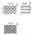
- All Figures 1 to 3correspond to partial views of filter blocks. It may in fact be the partial view of a monolithic filter body or the partial view of a filter body formed by assembling filter blocks.
- the thickness of the walls separating the different channelsis not to scale and does not constitute a limit to the invention.
- Figure 1ashows schematically the front face of a filter block currently used to retain the particles contained in the exhaust gas of motor vehicles propelled by a diesel engine.
- This filter blockcomprises all identical channels whose cross section is square and of constant dimension throughout the length of the filter body. On this front, every other channel is clogged. Channels 1 and 2 are open and therefore constitute so-called input channels. The channels 3 and 4 are clogged and therefore constitute so-called output channels.
- Figure 1bis a longitudinal sectional view along line AA of Figure 1a. The flow F of the exhaust gas enters the filter block through the inlet channels and then passes through the side walls of the channels to join the outlet channels.
- Figure 1cis a cross-sectional view of the extrusion die used to manufacture the filter blocks currently used and shown in Figure 1a. In this view, the solid lines represent the parts hollowed out by machining and in which the ceramic paste can pass.
- Figure 2ashows schematically the front face of a first embodiment of a filter block according to the invention.
- Channels 10 and 11are open and constitute the input channels.
- Channels 12 and 13are plugged and constitute the output channels.
- the channelsare organized in a network of deformed triangular cross section channels to increase the overall volume of the input channels at the expense of that of the output channels. This is how a wall
- the intermediate, non-planar, between an input channel and an output channelmay be concave on the input channel side, as shown in Fig. 2a, and convex on the output channel side.
- Figure 2bis a sectional view along the line AA of Figure 2a.
- the flow F of the exhaust gasenters the filter body through the inlet channels and then passes through the walls of the channels to join the outlet channels. Due to the increase in the overall volume of the input channels mentioned above, the area available on the walls of the input channels or "filtration surface" is increased (at the expense of that of the output channels) compared with to a filter body of the prior art such as that of Figure 1.
- the entire surface of the inlet channelsis advantageously used for the filtration of exhaust gases. Indeed, there is no zone (s) of one or more input channel (s) that opens (nt) in another input channel, zone (s) that can not be (are) useful for filtration since the exhaust gases can pass through them in both directions.
- the input and output channelsare parallel and rectilinear.
- Figure 2cis a cross-sectional view of the extrusion die used to make the filter block of Figure 3a; view on which the solid lines represent the parts hollowed out by machining and in which the ceramic paste can pass.
- This diemakes it possible to manufacture channels of constant cross sections over the entire length of the filter block, which facilitates their extrusion.
- the channelsare rectilinear depending on the length of the filter body.
- the channelsin longitudinal section (see Figure 2b), the channels have a straight section and constant over their entire length L. The manufacture of filter blocks is facilitated.
- the inlet channelshave a larger cross section than the outlet channels to increase the volume available for soot storage.
- the input and output channelsare arranged relative to each other such that all gas filtered by any input channel passes into output channels adjacent to that input channel, thereby optimizing the input channel. filtration area available for a determined filter block volume.
- FIG. 3schematizes the front face of another embodiment of a filter block according to the invention.
- Channels 10 and 11are open and constitute the input channels.
- Channels 12 and 13are plugged and constitute the output channels.
- the channelsare organized according to a network of distorted square cross-sectional channels to increase the overall volume of the input channels at the expense of that of the output channels.
- the input and output channelsare arranged alternately, forming a checkerboard pattern.
- the sidewall 14 of an inlet channel 11is therefore formed of four sidewall portions 14a-14d separating the interior volume of this channel from the four interior volumes of the four adjacent outlet channels, respectively.
- an intermediate wall 15, not planar, separating two horizontal rows R 1 and R 2 , and / or two vertical rows of channels (and thus formed by a set of side wall portions, referenced 16 1 to 16 8 , of these channels)is concave on the input channel side and convex on the output channel side.
- the intermediate wall 15preferably has, in cross-section, an undulating or "wave" shape ("wavy” in English), the wall 15 substantially waving a half wave length across the width of a channel.
- the corrugationis periodic, but the amplitude of the corrugations can be constant or variable. Preferably this amplitude is constant. More preferably, the corrugation has a sinusoidal shape whose half-period is equal to the pitch "p" of the channel network, as shown in FIG.
- all the intermediate walls 15 of a block, extending vertically or horizontallyhave, in cross-section, a corrugation of identical shape.
- the "asymmetry rate”designates the ratio between the amplitude "h” and the half length of said undulation (or between the amplitude "h” and the half-period in the case of a periodic undulation).
- Table 1The following examples, summarized in Table 1, are provided for illustrative and not limiting.
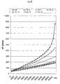
- Figures 4 and 5show the curves of increase of the pressure drop as a function of time corresponding to certain examples of Table 1, with clean and dirty filters, respectively.
- the filter bodies testedwere constituted by the assembly of 16 filter blocks secured by a 1 mm thick seal. These filter bodies were cylindrical with a diameter of 144 mm and a length of 9 inches (228.6 mm).
- the channelswere of the type shown in Fig. 4, the walls having a substantially sinusoidal profile, and the outlet and inlet channels having a constant cross-sectional area along the entire length L of the filter body.
- the exhaust gaseswere introduced into the inlet channels of the filter bodies tested at a temperature of 250 ° C. and at a flow rate of 320 m 3 / hour.
- the particulate concentration in these exhaustwas 2.2 10 -5 kg / m 3 .
- the concentration of combustion residues in the inlet channelswas 1.8 10 -9 m 3 / m 3 of exhaust gas.
- the reference example "Ref”corresponds to a filter constituted by the assembly of 16 filter blocks joined by a 1 mm thick gasket. This filter was cylindrical with a diameter of 144 mm and a length of 9 inches (228.6 mm).
- the channelswere of the type shown in FIG. 1, the exit and entry channels having a square cross-section of constant area along the entire length L of the filter body.
- the grating pitchwas 1.8 mm and the wall thickness was 350 ⁇ m.
- hydroaulic diameter of a cross-section or channelis meant the ratio of four times the section of the channel to the perimeter of the channel.
- the density of channelsis measured in number of channels per square inch (cpsi, ie, "cells per square inch”).
- Vedenotes the total volume of the input channels, Vs the total volume of the output channels.
- filtration surfaceis meant the surface of the walls of the inlet channels that may be traversed by the gas stream to be filtered.
- the filtration areais evaluated in square meters per liter of filter block.
- the measurement of the duration "t” in minutes to reach a pressure drop "dP" of x mbaris noted t / x .
- the larger the filtration areathe faster the increase in pressure drop over time. In other words, the loading slope is even lower than the filtration area is large.
- the filtration surfaceis however not the only criterion as shown by a comparison of Example 15 and the reference example. This comparison shows that, according to the invention, a higher ratio r advantageously makes it possible to compensate for a lower filtration area when the filters are fouled.
- a high ratiomeans greater volume in the inlet channels for storing combustion residues.
- a volume of combustion residuesi.e., a number of regenerations
- the proportion of the filtration area inefficient due to recovery by the combustion residuesis therefore lower . This results in a lower induced loss of charge. Between two regenerations, the pressure drop induced by the filter body therefore increases more slowly.
- the larger volume in the inlet channelsmakes it possible to store a larger amount of combustion residues.
- the number of regenerations before disassembly / reassembly of the filtercan be increased.
- an increase in the asymmetry rateimplies an increase in the storage capacity of the input channels and an increase in the filtration area of the block.
- the asymmetry ratemust not be increased excessively, otherwise the output channel section may be reduced as a result of a detrimental increase in the pressure drop.
- the level of asymmetryis less than 20%, preferably 15%, preferably less than 12%, and greater than 5%, preferably greater than 6%.
- the duration between two disassembly / cleaning operations of the filter bodyis therefore increased not only because of a residual fouling of the filtration surface by the lower combustion residues after each regeneration, which allows a fouling by soot slower between two regenerations, but also because a greater number of regenerations is possible, the storage volume of the combustion residues being greater.
- the motoristcan therefore travel a greater number of kilometers without maintenance on the filter.
- the increase in the ratio rresults from an increase in the hydraulic diameter of the inlet channels and / or a decrease in the hydraulic diameter of the outlet channels. It can be seen from Table 1 (see especially Examples 3, 6 and 10) that when the hydraulic diameter of the outlet channels is very small, the pressure drop induced by the clean filter body is much too high. This can be unacceptable since the power approval of the engines takes into account the exhaust line.
- the hydraulic diameter of the outlet channelsmust be greater than or equal to 0.9 mm and preferably between 0.95 and 1.4 mm.
- the inventionalso relates to a monolithic filter body.
- the filter blockcould have any shape, any channel arrangement.
- cross section of the channelsis not limited to the forms described.
Landscapes
- Physics & Mathematics (AREA)
- Geometry (AREA)
- Chemical & Material Sciences (AREA)
- Chemical Kinetics & Catalysis (AREA)
- Engineering & Computer Science (AREA)
- Combustion & Propulsion (AREA)
- Mechanical Engineering (AREA)
- General Engineering & Computer Science (AREA)
- Filtering Of Dispersed Particles In Gases (AREA)
- Processes For Solid Components From Exhaust (AREA)
- Filtering Materials (AREA)
Abstract
Description
Translated fromFrenchL'invention se rapporte à un bloc filtrant pour la filtration des particules contenues dans les gaz d'échappement des moteurs à combustion interne, en particulier du type diesel, et à un corps filtrant comportant au moins un bloc filtrant selon l'invention.The invention relates to a filter block for the filtration of particles contained in the exhaust gases of internal combustion engines, in particular of the diesel type, and to a filter body comprising at least one filter block according to the invention.
Des structures poreuses en nid d'abeille sont utilisées comme corps filtrants pour la filtration des particules émises par les véhicules diesel. Généralement, ces corps filtrants sont en céramique (cordiérite, carbure de silicium, ...). Ils peuvent être monolithiques ou bien constitués de différents blocs. Dans ce dernier cas, les blocs sont assemblés entre eux par collage au moyen d'un ciment céramique. Le tout est ensuite usiné pour prendre la section souhaitée, circulaire ou elliptique en générale. Le corps filtrant comporte une pluralité de canaux. Il est inséré dans une enceinte métallique. Chaque canal est obturé à l'une ou l'autre de ses extrémités. Il existe ainsi des canaux d'entrée et des canaux de sortie. Les gaz d'échappement sont ainsi contraints à traverser les parois latérales des canaux d'entrée pour rejoindre les canaux de sortie ; c'est ainsi que les particules ou suies se déposent dans le corps filtrant.Porous honeycomb structures are used as filter bodies for the filtration of particles emitted by diesel vehicles. Generally, these filtering bodies are ceramic (cordierite, silicon carbide, etc.). They can be monolithic or consist of different blocks. In the latter case, the blocks are assembled together by bonding with a ceramic cement. Everything is then machined to take the desired section, circular or elliptical in general. The filter body has a plurality of channels. It is inserted in a metal enclosure. Each channel is closed at one or other of its ends. There are thus input channels and output channels. The exhaust gases are thus forced to pass through the sidewalls of the inlet channels to reach the outlet channels; this is how the particles or soot are deposited in the filter body.
Après un certain temps d'utilisation, des suies s'accumulent dans les canaux du corps filtrant ce qui augmente la perte de charge due au filtre et altère les performances du moteur. Pour cette raison, le corps filtrant doit être régénéré régulièrement, classiquement après environ 7 à 10 heures de fonctionnement, quand la perte de charge a atteint une valeur d'environ 150 dPa (pour un moteur d'environ 2 litres de cylindrée fonctionnant sur autoroute avec un corps filtrant d'environ 4 litres).After a period of use, soot accumulates in the channels of the filter body which increases the pressure drop due to the filter and impairs the performance of the engine. For this reason, the filter body must be regenerated regularly, typically after about 7 to 10 hours of operation, when the pressure drop has reached a value of about 150 dPa (for a motor of about 2 liters of displacement operating on motorway with a filter body of about 4 liters).
La régénération consiste à oxyder les suies. Pour ce faire, il est nécessaire de chauffer celles-ci puisque la température des gaz d'échappement est de l'ordre de 300°C alors que la température d'auto inflammation des suies est plutôt de l'ordre de 600°C, dans des conditions de fonctionnement classiques. Malgré cette régénération, des résidus de combustion restent dans le corps filtrant. Ainsi, la perte de charge induite par le corps filtrant après régénération est toujours plus importante que celle induite par le corps filtrant avant régénération. Ce phénomène d'encrassement se poursuit à chaque régénération et il est nécessaire de nettoyer complètement le bloc filtrant chez le garagiste, par exemple tous les 80 000 km. Ce nettoyage constitue un inconvénient à l'utilisation des corps filtrants.Regeneration consists of oxidizing soot. To do this, it is necessary to heat them since the temperature of the exhaust gas is of the order of 300 ° C while the self-ignition temperature of the soot is rather of the order of 600 ° C, in conventional operating conditions. Despite this regeneration, combustion residues remain in the filter body. Thus, the pressure loss induced by the filter body after regeneration is always greater than that induced by the filter body before regeneration. This phenomenon of fouling continues with each regeneration and it is necessary to clean completely the filter block at the garage, for example every 80 000 km. This cleaning is a disadvantage to the use of the filter bodies.
FR 2 473 113 propose un corps filtrant qu'il est possible d'obtenir par extrusion et présentant des canaux d'entrée de section transversale supérieure à celle des canaux de sortie. Les auteurs indiquent une surface de filtration de 7,89 cm2/cm3 de bloc filtrant (soit 0,789 m2/l) avec une section transversale des canaux d'entrée constante et inférieure à 12,9 mm2 et une épaisseur de paroi inférieure ou égale à 0,7 mm.
Le corps filtrant décrit dans FR 2 473 113 induit cependant une perte de charge importante, ce qui signifie que le corps filtrant doit être régénéré fréquemment. L'exploitation industrielle de ce corps filtrant est donc difficilement envisageable.The filter body described in
Il existe donc un besoin pour un corps filtrant présentant une perte de charge réduite, à tout moment de sa durée de vie, et nécessitant ainsi un nettoyage moins fréquent. L'invention vise à satisfaire ce besoin.There is therefore a need for a filter body having a reduced pressure drop, at any time during its lifetime, and thus requiring less frequent cleaning. The invention aims to satisfy this need.
Plus particulièrement, l'invention concerne un bloc filtrant pour la filtration des particules contenues dans les gaz d'échappement d'un moteur à combustion interne, comprenant des ensembles imbriqués de canaux d'entrée et de canaux de sortie adjacents, lesdits canaux d'entrée et de sortie étant en communication de fluide par leurs parois latérales, lesdites parois latérales présentant, en coupe transversale, une ondulation déterminée de manière à accroître le volume global des canaux d'entrée aux dépens de celui des canaux de sortie, et le volume global des canaux d'entrée étant supérieur à celui des canaux de sortie, remarquable en ce que
- le diamètre hydraulique desdits canaux de sortie est compris entre 0,9 et 1,4 mm, de préférence supérieur à 0,95 mm,
- le rapport r du volume global des canaux d'entrée sur le volume global des canaux de sortie est compris entre 1,15 et 4, de préférence supérieur à 1,35 et/ou inférieur à 3,
- la surface de filtration est comprise entre 0,825 m2 et 1,4 m2 par litre dudit bloc filtrant, de préférence supérieure à 0,92 m2,
- le taux d'asymétrie de ladite ondulation est inférieur à 20%.
- the hydraulic diameter of said outlet channels is between 0.9 and 1.4 mm, preferably greater than 0.95 mm,
- the ratio r of the total volume of the input channels to the overall volume of the output channels is between 1.15 and 4, preferably greater than 1.35 and / or less than 3,
- the filtration area is between 0.825 m2 and 1.4 m2 per liter of said filter block, preferably greater than 0.92 m2 ,
- the asymmetry rate of said undulation is less than 20%.
Comme on le verra plus en détail dans la suite de la description, cette particularité permet de diminuer sensiblement la perte de charge induite par le bloc filtrant, et donc de diminuer la fréquence de la régénération du corps filtrant auquel il appartient.As will be seen in more detail in the following description, this feature allows to significantly reduce the pressure loss induced by the block filtering, and thus reduce the frequency of regeneration of the filter body to which it belongs.
Selon d'autres caractéristiques préférées de l'invention,
- lesdits canaux de sortie ont une section transversale de surface constante sur toute la longueur dudit bloc filtrant ;
- lesdits canaux d'entrée et de sortie sont rectilignes et parallèles ;
- lesdits canaux d'entrée et de sortie sont agencés les uns par rapport aux autres de manière que l'intégralité du gaz filtré par un canal d'entrée quelconque passe dans des canaux de sortie adjacents audit canal d'entrée ;
- ladite ondulation présente, en coupe transversale, une forme sinusoïdale;le taux d'asymétrie de ladite ondulation est inférieur à 15%, de préférence inférieur à 12%, et/ou supérieur à 5%, de préférence supérieur à 6%;
- ladite ondulation est périodique et une demi-période de ladite ondulation s'étend sur la largeur d'un desdits canaux.
- lesdits canaux d'entrée et de sortie sont disposés en alternance suivant un rang horizontal ou vertical quelconque dudit bloc, formant ainsi sur la face avant ou arrière du bloc une structure en damier.
- said output channels have a constant cross-sectional area along the entire length of said filter block;
- said input and output channels are rectilinear and parallel;
- said input and output channels are arranged relative to each other such that all gas filtered by any input channel passes into output channels adjacent to said input channel;
- said corrugation has a sinusoidal shape in cross-section, the asymmetry rate of said corrugation is less than 15%, preferably less than 12%, and / or greater than 5%, preferably greater than 6%;
- said corrugation is periodic and a half-period of said undulation extends over the width of one of said channels.
- said input and output channels are arranged alternately in any horizontal or vertical row of said block, thus forming on the front or rear face of the block a checkerboard structure.
L'invention concerne également un corps filtrant destiné à un filtre à particules, remarquable en ce qu'il comporte au moins un bloc filtrant conforme à l'invention.The invention also relates to a filter body for a particulate filter, remarkable in that it comprises at least one filter block according to the invention.
La description qui va suivre, faite en se référant au dessin annexé, ainsi que les exemples permettront de mieux comprendre et apprécier les avantages de l'invention. Dans ce dessin :
- la figure 1a est une vue partielle de la face avant (c'est-à-dire celle sur laquelle les gaz d'échappement arrivent) d'un bloc filtrant de l'art antérieur, alors que la figure 1b est une vue en coupe de ce bloc selon le trait de coupe AA de la figure 1a et que la figure 1c est une vue en coupe transversale d'une filière d'extrusion conçue pour fabriquer ce bloc filtrant,
- les figures 2a à 2c sont des vues analogues à celles des figures 1a à 1c, respectivement, et illustrent un premier mode de réalisation d'un corps filtrant suivant l'invention,
- la figure 3 est une vue partielle de la face avant d'un bloc filtrant selon l'invention, selon un deuxième mode de réalisation de l'invention,
- la figure 4 est un graphe représentant la perte de charge en fonction du temps d'utilisation, pour différents corps filtrants neufs, dits « propres », testés.
- la figure 5 est un graphe représentant la perte de charge en fonction du temps d'utilisation, pour différents corps filtrants testés dans lesquels les résidus de combustion occupent un volume correspondant à 50% du volume des canaux d'entrée du filtre de référence, ce qui correspond à une distance parcourue par le véhicule d'environ 80 000 km. De tels corps filtrants sont dits "encrassés". Les résidus sont généralement dans le fond du canal d'entrée.
- FIG. 1a is a partial view of the front face (that is to say the one on which the exhaust gases arrive) of a filter block of the prior art, whereas FIG. 1b is a sectional view. of this block according to the section line AA of FIG. 1a and that FIG. 1c is a cross-sectional view of an extrusion die designed to manufacture this filter block,
- FIGS. 2a to 2c are views similar to those of FIGS. 1a to 1c, respectively, and illustrate a first embodiment of a filter body according to the invention,
- FIG. 3 is a partial view of the front face of a filter block according to the invention, according to a second embodiment of the invention,
- Figure 4 is a graph showing the pressure drop as a function of the time of use, for different new filter bodies, called "clean", tested.
- FIG. 5 is a graph representing the pressure drop as a function of the time of use, for different filter bodies tested in which the combustion residues occupy a volume corresponding to 50% of the volume of the input channels of the reference filter, this which corresponds to a distance traveled by the vehicle of about 80 000 km. Such filter bodies are said to be "fouled". The residues are usually in the bottom of the inlet channel.
Toutes les figures 1 à 3 correspondent à des vues partielles de blocs filtrants. Il peut en fait s'agir de la vue partielle d'un corps filtrant monolithique ou bien de la vue partielle d'un corps filtrant formé par assemblage de blocs filtrants.All Figures 1 to 3 correspond to partial views of filter blocks. It may in fact be the partial view of a monolithic filter body or the partial view of a filter body formed by assembling filter blocks.
Sur ces figures, l'épaisseur des parois séparant les différents canaux n'est pas à l'échelle et ne constitue pas une limite à l'invention.In these figures, the thickness of the walls separating the different channels is not to scale and does not constitute a limit to the invention.
La figure 1a schématise la face avant d'un bloc filtrant utilisé actuellement pour retenir les particules contenues dans les gaz d'échappement de véhicules automobiles propulsés par un moteur diesel. Ce bloc filtrant comporte des canaux tous identiques dont la section transversale est carrée et de dimension constante dans toute la longueur du corps filtrant. Sur cette face avant, un canal sur deux est bouché. Les canaux 1 et 2 sont ouverts et constituent donc des canaux dits d'entrée. Les canaux 3 et 4 sont bouchés et constituent donc des canaux dits de sortie. La figure 1 b est une vue de coupe longitudinale selon le trait AA de la figure 1 a. Le flux F des gaz d'échappement entre dans le bloc filtrant par les canaux d'entrée et traverse ensuite les parois latérales des canaux pour rejoindre les canaux de sortie. La figure 1c est une vue de coupe transversale de la filière d'extrusion utilisée pour fabriquer les blocs filtrants utilisés actuellement et représentés selon la figure 1 a. Sur cette vue, les traits pleins représentent les parties évidées par usinage et dans lesquelles la pâte céramique pourra passer.Figure 1a shows schematically the front face of a filter block currently used to retain the particles contained in the exhaust gas of motor vehicles propelled by a diesel engine. This filter block comprises all identical channels whose cross section is square and of constant dimension throughout the length of the filter body. On this front, every other channel is clogged.
La figure 2a schématise la face avant d'un premier mode de réalisation d'un bloc filtrant selon l'invention. Les canaux 10 et 11 sont ouverts et constituent les canaux d'entrée. Les canaux 12 et 13 sont bouchés et constituent les canaux de sortie. Les canaux sont organisés selon un réseau de canaux de section transversale triangulaire déformée pour accroître le volume global des canaux d'entrée aux dépens de celui des canaux de sortie. C'est ainsi qu'une paroi intermédiaire, non plane, entre un canal d'entrée et un canal de sortie peut être concave du côté du canal d'entrée, comme représenté à la figure 2a, et convexe du côté du canal de sortie.Figure 2a shows schematically the front face of a first embodiment of a filter block according to the invention.
La figure 2b est une vue en coupe selon le trait AA de la figure 2a. Le flux F des gaz d'échappement entre dans le corps filtrant par les canaux d'entrée et traverse ensuite les parois des canaux pour rejoindre les canaux de sortie. Du fait de l'accroissement du volume global des canaux d'entrée mentionné plus haut, la surface disponible sur les parois des canaux d'entrée ou "surface de filtration" se trouve augmentée (au détriment de celle des canaux de sortie) par rapport à un corps filtrant de l'art antérieur tel que celui de la figure 1.Figure 2b is a sectional view along the line AA of Figure 2a. The flow F of the exhaust gas enters the filter body through the inlet channels and then passes through the walls of the channels to join the outlet channels. Due to the increase in the overall volume of the input channels mentioned above, the area available on the walls of the input channels or "filtration surface" is increased (at the expense of that of the output channels) compared with to a filter body of the prior art such as that of Figure 1.
Toute la surface des canaux d'entrée sert avantageusement à la filtration des gaz d'échappement. En effet, il n'existe pas de zone(s) d'un ou plusieurs canal(aux) d'entrée qui débouche(nt) dans un autre canal d'entrée, zone(s) qui ne peu(ven)t être utile(s) à la filtration puisque les gaz d'échappement peuvent la (les) traverser dans les deux sens.The entire surface of the inlet channels is advantageously used for the filtration of exhaust gases. Indeed, there is no zone (s) of one or more input channel (s) that opens (nt) in another input channel, zone (s) that can not be (are) useful for filtration since the exhaust gases can pass through them in both directions.
De préférence, les canaux d'entrée et de sortie sont parallèles et rectilignes. Avantageusement, il est ainsi possible de fabriquer le bloc filtrant selon l'invention par extrusion.Preferably, the input and output channels are parallel and rectilinear. Advantageously, it is thus possible to manufacture the filter block according to the invention by extrusion.
La figure 2c est une vue de coupe transversale de la filière d'extrusion utilisée pour réaliser le bloc filtrant de la figure 3a ; vue sur laquelle les traits pleins représentent les parties évidées par usinage et dans lesquelles la pâte céramique pourra passer. Cette filière permet de fabriquer des canaux de sections transversales constantes sur toute la longueur du bloc filtrant, ce qui facilite leur extrusion.Figure 2c is a cross-sectional view of the extrusion die used to make the filter block of Figure 3a; view on which the solid lines represent the parts hollowed out by machining and in which the ceramic paste can pass. This die makes it possible to manufacture channels of constant cross sections over the entire length of the filter block, which facilitates their extrusion.
Les canaux sont rectilignes suivant la longueur du corps filtrant. Ainsi, en coupe longitudinale (voir figure 2b), les canaux ont une section droite et constante sur toute leur longueur L. La fabrication des blocs filtrants en est facilitée.The channels are rectilinear depending on the length of the filter body. Thus, in longitudinal section (see Figure 2b), the channels have a straight section and constant over their entire length L. The manufacture of filter blocks is facilitated.
Les canaux d'entrée ont une section transversale supérieure à celle des canaux de sortie afin d'augmenter le volume disponible pour le stockage des suies. Les canaux d'entrée et de sortie sont agencés les uns par rapport aux autres de manière que l'intégralité du gaz filtré par un canal d'entrée quelconque passe dans des canaux de sortie adjacents à ce canal d'entrée, ce qui optimise le surface de filtration disponible pour un volume de bloc filtrant déterminé.The inlet channels have a larger cross section than the outlet channels to increase the volume available for soot storage. The input and output channels are arranged relative to each other such that all gas filtered by any input channel passes into output channels adjacent to that input channel, thereby optimizing the input channel. filtration area available for a determined filter block volume.
La figure 3 schématise la face avant d'un autre mode de réalisation d'un bloc filtrant selon l'invention. Les canaux 10 et 11 sont ouverts et constituent les canaux d'entrée. Les canaux 12 et 13 sont bouchés et constituent les canaux de sortie. Les canaux sont organisés selon un réseau de canaux de section transversale carrée déformée pour accroître le volume global des canaux d'entrée aux dépens de celui des canaux de sortie. Selon un rang horizontal (x) ou vertical (y) quelconque, les canaux d'entrée et de sortie sont disposés en alternance, formant une structure en damier. La paroi latérale 14 d'un canal d'entrée 11 est donc formée de quatre portions de paroi latérale 14a-14d séparant le volume intérieur de ce canal des quatre volumes intérieurs des quatre canaux de sortie adjacents, respectivement.FIG. 3 schematizes the front face of another embodiment of a filter block according to the invention.
De préférence, une paroi intermédiaire 15, non plane, séparant deux rangs horizontaux R1 et R2, et/ou deux rangs verticaux, de canaux (et donc formée par un ensemble de portions de parois latérales, référencées 161 à 168, de ces canaux) est concave du côté des canaux d'entrée et convexe du côté des canaux de sortie.Preferably, an
En suivant un rang horizontal (selon l'axe x) ou vertical (selon l'axe y) de canaux, la paroi intermédiaire 15, présente de préférence, en coupe transversale, une forme ondulée ou « en vague » (« wavy » en anglais), la paroi 15 ondulant sensiblement d'une demi longueur d'ondulation sur la largeur d'un canal.By following a horizontal (along the x-axis) or vertical (along the y-axis) row of channels, the
On appelle "longueur" d'une ondulation, la distance séparant deux points de cette ondulation localisée à une même hauteur, avec le même sens de variation de pente. Dans le cas d'une ondulation périodique, la "longueur" de l'ondulation est appelée "période".The term "length" of a ripple, the distance separating two points of this localized ripple at the same height, with the same direction of variation of slope. In the case of a periodic ripple, the "length" of the ripple is called "period".
De préférence l'ondulation est périodique, mais l'amplitude des ondulations peut être constante ou variable. De préférence cette amplitude est constante. De préférence encore, l'ondulation présente une forme sinusoïdale dont la demi-période est égale au pas "p" du réseau de canaux, comme représenté sur la figure 3.Preferably the corrugation is periodic, but the amplitude of the corrugations can be constant or variable. Preferably this amplitude is constant. More preferably, the corrugation has a sinusoidal shape whose half-period is equal to the pitch "p" of the channel network, as shown in FIG.
De préférence enfin, toutes les parois intermédiaires 15 d'un bloc, s'étendant verticalement ou horizontalement, présentent, en coupe transversale, une ondulation de forme identique.Finally, preferably, all the
Le « taux d'asymétrie » désigne le rapport entre l'amplitude « h » et la demi longueur de ladite ondulation (ou entre l'amplitude "h" et la demi-période dans le cas d'une ondulation périodique). Les exemples suivants, résumés dans le tableau 1, sont fournis à titre illustratif et non limitatif. Les figures 4 et 5 représentent les courbes d'augmentation de la perte de charge en fonction du temps correspondant à certains exemples du tableau 1, avec des filtres propres et encrassés, respectivement.The "asymmetry rate" designates the ratio between the amplitude "h" and the half length of said undulation (or between the amplitude "h" and the half-period in the case of a periodic undulation). The following examples, summarized in Table 1, are provided for illustrative and not limiting. Figures 4 and 5 show the curves of increase of the pressure drop as a function of time corresponding to certain examples of Table 1, with clean and dirty filters, respectively.
Les corps filtrants testés étaient constitués par l'assemblage de 16 blocs filtrants solidarisés par un joint d'épaisseur 1 mm. Ces corps filtrants étaient cylindriques avec un diamètre de 144 mm et une longueur de 9 pouces (soit 228,6 mm). Les canaux étaient du type de ceux représentés sur la figure 4, les parois ayant un profil sensiblement sinusoïdal, et les canaux de sortie et d'entrée ayant une section transversale de surface constante sur toute la longueur L du corps filtrant.The filter bodies tested were constituted by the assembly of 16 filter blocks secured by a 1 mm thick seal. These filter bodies were cylindrical with a diameter of 144 mm and a length of 9 inches (228.6 mm). The channels were of the type shown in Fig. 4, the walls having a substantially sinusoidal profile, and the outlet and inlet channels having a constant cross-sectional area along the entire length L of the filter body.
Pour les besoins des calculs, les gaz d'échappement ont été introduits dans les canaux d'entrée des corps filtrants testés à une température de 250°C et avec un débit de 320 m3/heure. La concentration en particules dans ces gaz d'échappement était de 2,2 10-5 kg/m3.For the purposes of the calculations, the exhaust gases were introduced into the inlet channels of the filter bodies tested at a temperature of 250 ° C. and at a flow rate of 320 m3 / hour. The particulate concentration in these exhaust was 2.2 10-5 kg / m3 .
Pour les tests des corps filtrants encrassés, la concentration en résidus de combustion dans les canaux d'entrée était de 1,8 10-9 m3/m3 de gaz d'échappement.For the fouled filter body tests, the concentration of combustion residues in the inlet channels was 1.8 10-9 m3 / m3 of exhaust gas.
L'exemple de référence « Ref » correspond à un filtre constitué par l'assemblage de 16 blocs filtrants solidarisés par un joint d'épaisseur 1 mm. Ce filtre était cylindrique avec un diamètre de 144 mm et une longueur de 9 pouces (soit 228,6 mm). Les canaux étaient du type de ceux représentés sur la figure 1, les canaux de sortie et d'entrée ayant une section transversale carrée de surface constante sur toute la longueur L du corps filtrant. Le pas du réseau était de 1,8 mm et l'épaisseur des parois de 350 µm.The reference example "Ref" corresponds to a filter constituted by the assembly of 16 filter blocks joined by a 1 mm thick gasket. This filter was cylindrical with a diameter of 144 mm and a length of 9 inches (228.6 mm). The channels were of the type shown in FIG. 1, the exit and entry channels having a square cross-section of constant area along the entire length L of the filter body. The grating pitch was 1.8 mm and the wall thickness was 350 μm.
Les calculs des surfaces de filtration, des volumes de canaux et des pertes de charge ont été réalisés par l'Institut de Mécaniques des Fluides de Toulouse (France).Calculations of the filtration surfaces, channel volumes and pressure losses were carried out by the Institute of Fluid Mechanics of Toulouse (France).
Par « diamètre hydraulique » d'une section transversale ou d'un canal, on entend le rapport entre quatre fois la section du canal et le périmètre du canal.By "hydraulic diameter" of a cross-section or channel is meant the ratio of four times the section of the channel to the perimeter of the channel.
La densité de canaux est mesurée en nombre de canaux par pouce carré (cpsi, c'est-à-dire, en anglais, « cells per square inch »).The density of channels is measured in number of channels per square inch (cpsi, ie, "cells per square inch").
Ve désigne le volume total des canaux d'entrée, Vs le volume total des canaux de sortie. On définit le rapport r de la manière suivante : r = Ve/Vs.Ve denotes the total volume of the input channels, Vs the total volume of the output channels. The ratio r is defined in the following way: r = Ve / Vs.
Par « surface de filtration », on entend la surface des parois des canaux d'entrée susceptible d'être traversée par le flux gazeux à filtrer. La surface de filtration est évaluée en mètres carrés par litre de bloc filtrant.By "filtration surface" is meant the surface of the walls of the inlet channels that may be traversed by the gas stream to be filtered. The filtration area is evaluated in square meters per liter of filter block.
Les performances d'un corps filtrant sont évaluées par la mesure de la durée « t » en minutes pour atteindre une perte de charge « dP » déterminée, et par la perte de charge initiale (dP pour t = 0). La mesure de la durée « t » en minutes pour atteindre une perte de charge « dP » de x mbar est notée t/x.The performance of a filter body is evaluated by measuring the duration "t" in minutes to reach a determined pressure drop "dP", and by the initial pressure drop (dP for t = 0). The measurement of the duration "t" in minutes to reach a pressure drop "dP" of x mbar is noted t/ x .
On considère qu'il est avantageux qu'un corps filtrant respecte les critères suivants :
- Perte de charge initiale inférieure à 50 mbar ;
- t/100 ≥ 300 pour un filtre propre ;
- t/150 ≥ 500 pour un filtre propre ;
- t/150 ≥ 200 pour un filtre encrassé.


- Initial pressure drop of less than 50 mbar;
- t/ 100 ≥ 300 for a clean filter;
- t/ 150 ≥ 500 for a clean filter;
- t/ 150 ≥ 200 for a dirty filter.
Pour les corps filtrants neufs, plus la surface de filtration est grande, plus l'augmentation, dans le temps, de la perte de charge est lente. Autrement dit, la pente de chargement est d'autant plus faible que la surface de filtration est grande. La surface de filtration n'est cependant pas le seul critère comme le montre une comparaison de l'exemple 15 et de l'exemple de référence. Cette comparaison fait apparaître que, selon l'invention, un rapport r supérieur permet avantageusement de compenser une surface de filtration inférieure lorsque les filtres sont encrassés.For new filter bodies, the larger the filtration area, the faster the increase in pressure drop over time. In other words, the loading slope is even lower than the filtration area is large. The filtration surface is however not the only criterion as shown by a comparison of Example 15 and the reference example. This comparison shows that, according to the invention, a higher ratio r advantageously makes it possible to compensate for a lower filtration area when the filters are fouled.
Sans être lié par aucune théorie, la Demanderesse explique ce phénomène de la manière suivante.Without being bound by any theory, the Applicant explains this phenomenon in the following manner.
Un rapport r élevé signifie un plus grand volume dans les canaux d'entrée pour stocker les résidus de combustion. Pour une surface de filtration et un volume de résidus de combustion (c'est-à-dire un nombre de régénérations) donnés, la proportion de la surface de filtration inefficace du fait d'un recouvrement par les résidus de combustion est donc plus faible. Il en résulte une perte de charge induite plus faible. Entre deux régénérations, la perte de charge induite par le corps filtrant augmente donc plus lentement.A high ratio means greater volume in the inlet channels for storing combustion residues. For a given filtration area and a volume of combustion residues (i.e., a number of regenerations), the proportion of the filtration area inefficient due to recovery by the combustion residues is therefore lower . This results in a lower induced loss of charge. Between two regenerations, the pressure drop induced by the filter body therefore increases more slowly.
En outre, le plus grand volume dans les canaux d'entrée permet de stocker une plus grande quantité de résidus de combustion. Le nombre de régénérations avant démontage/remontage du filtre peut donc être augmenté.In addition, the larger volume in the inlet channels makes it possible to store a larger amount of combustion residues. The number of regenerations before disassembly / reassembly of the filter can be increased.
A épaisseur de paroi constante, une augmentation du taux d'asymétrie implique une augmentation de capacité de stockage des canaux d'entrée et une augmentation de la surface de filtration du bloc.At a constant wall thickness, an increase in the asymmetry rate implies an increase in the storage capacity of the input channels and an increase in the filtration area of the block.
Le taux d'asymétrie ne doit cependant pas être augmenté excessivement sous peine d'entraîner une réduction de la section des canaux de sortie telle qu'il en résulte une augmentation préjudiciable de la perte de charge.However, the asymmetry rate must not be increased excessively, otherwise the output channel section may be reduced as a result of a detrimental increase in the pressure drop.
Un compromis doit donc être déterminé. De préférence, le taux d'asymétrie est inférieur à 20%, de préférence à 15%, de préférence inférieur à 12%, et supérieur à 5%, de préférence supérieur à 6%.A compromise must therefore be determined. Preferably, the level of asymmetry is less than 20%, preferably 15%, preferably less than 12%, and greater than 5%, preferably greater than 6%.
Selon l'invention, la durée entre deux opérations de démontage/nettoyage du corps filtrant est donc augmentée non seulement du fait d'un encrassement résiduel de la surface de filtration par les résidus de combustion plus faible après chaque régénération, ce qui permet un encrassement par les suies plus lent entre deux régénérations, mais aussi du fait qu'un plus grand nombre de régénérations est possible, le volume de stockage des résidus de combustion étant plus grand.According to the invention, the duration between two disassembly / cleaning operations of the filter body is therefore increased not only because of a residual fouling of the filtration surface by the lower combustion residues after each regeneration, which allows a fouling by soot slower between two regenerations, but also because a greater number of regenerations is possible, the storage volume of the combustion residues being greater.
L'automobiliste pourra donc parcourir un plus grand nombre de kilomètres sans faire de maintenance sur le filtre.The motorist can therefore travel a greater number of kilometers without maintenance on the filter.
Selon l'invention, on considère qu'il est optimal d'avoir
- un rapport r supérieur ou égal à 1,15, de préférence supérieur à 1,35, et inférieur à 4 et, de préférence inférieur à 3,
- une surface de filtration au moins égale à 0,825 m2 par litre de bloc filtrant, de préférence supérieure ou égale à 0,92 m2 par litre de bloc filtrant.
- a ratio r greater than or equal to 1.15, preferably greater than 1.35, and less than 4 and, preferably less than 3,
- a filtration area at least equal to 0.825 m2 per liter of filter block, preferably greater than or equal to 0.92 m2 per liter of filter block.
Les canaux de sortie et d'entrée ayant une section transversale de surface constante sur toute la longueur du bloc filtrant, l'augmentation du rapport r résulte d'une augmentation du diamètre hydraulique des canaux d'entrée et/ou d'une diminution du diamètre hydraulique des canaux de sortie. On constate sur le tableau 1 (voir notamment les exemples 3, 6 et 10) que lorsque le diamètre hydraulique des canaux de sortie est très faible, la perte de charge induite par le corps filtrant propre est beaucoup trop élevée. Ceci peut être rédhibitoire puisque l'homologation en puissance des moteurs tient compte de la ligne d'échappement.Since the outlet and inlet channels have a constant cross-sectional area over the entire length of the filter block, the increase in the ratio r results from an increase in the hydraulic diameter of the inlet channels and / or a decrease in the hydraulic diameter of the outlet channels. It can be seen from Table 1 (see especially Examples 3, 6 and 10) that when the hydraulic diameter of the outlet channels is very small, the pressure drop induced by the clean filter body is much too high. This can be unacceptable since the power approval of the engines takes into account the exhaust line.
Selon l'invention, le diamètre hydraulique des canaux de sortie doit être supérieur ou égal à 0,9 mm et, de préférence, compris entre 0,95 et 1,4 mm.According to the invention, the hydraulic diameter of the outlet channels must be greater than or equal to 0.9 mm and preferably between 0.95 and 1.4 mm.
Bien entendu, la présente invention n'est pas limitée aux modes de réalisation décrits et représentés ci-dessus, fournis à titre illustratif et non limitatif.Of course, the present invention is not limited to the embodiments described and shown above, provided for illustrative and non-limiting.
Ainsi l'invention concerne également un corps filtrant monolithique. Le bloc filtrant pourrait avoir une forme quelconque, un arrangement de canaux quelconque.Thus the invention also relates to a monolithic filter body. The filter block could have any shape, any channel arrangement.
Enfin, la section transversale des canaux n'est pas limitée aux formes décrites.Finally, the cross section of the channels is not limited to the forms described.
Claims (14)
- Filtration unit for filtration of particles contained in the exhaust gas of an internal combustion engine, comprising interlaced sets of adjacent input channels (10, 11) and output channels (12, 13) which are in fluid communication through their side walls, said unit comprising a set of portions of side walls (161-168) that forms an intermediate wall (15) between the input (10, 11) and output channels (12, 13) and in cross-section has an undulation determined so as to increase the global volume of said input channels (10,11) at the expense of that of the output channels (12, 13), the global volume (Ve) of said input channels (10, 11) being greater than that (Vs) of said output channels (12, 13),characterised in that- the hydraulic diameter of said output channels (12, 13) is between 0.9 and 1.4 mm,- the ratio r of the global volume (Ve) of the input channels (10, 11) over the global volume (Vs) of the output channels (12, 13) is between 1.15 and 4,- the filtration surface area is between 0.825 m2 and 1.4 m2 per litre of said filtration unit,- the asymmetry rate of said undulation is less than 20%.
- Filtration unit according to claim 1,characterised in that the hydraulic diameter of said output channels (12, 13) is greater than 0.95 mm.
- Filtration unit according to one of claims 1 and 2,characterised in that said ratio r is greater than 1.35.
- Filtration unit according to any of the preceding claims,characterised in that said ratio r is less than 3.
- Filtration unit according to any of the preceding claims,characterised in that the filtration surface area is greater than 0.92 m2 per litre of said filtration unit.
- Filtration unit according to any of the preceding claims,characterised in that said output channels (12, 13) have a cross-section of constant area over the entire length (L) of said filtration unit.
- Filtration unit according to any of the preceding claims,characterised in that said input channels (10, 11) and output channels (12, 13) are rectilinear and parallel.
- Filtration unit according to any of the preceding claims,characterised in that said input channels (10, 11) and output channels (12, 13) are arranged in relation to each other such that the integrality of the gas filtered through any input channel (10, 11) passes into output channels (12, 13) adjacent to said input channel (10, 11).
- Filtration unit according to any of the preceding claims,characterised in that the asymmetry rate of said undulation is less than 15%.
- Filtration unit according to any of the preceding claims,characterised in that the asymmetry rate of said undulation is less than 12%.
- Filtration unit according to any of the preceding claims,characterised in that the asymmetry rate of said undulation is greater than 5%.
- Filtration unit according to any of the preceding claims,characterised in that the said undulation is periodic and a half period of said undulation extends over the width of one of said channels (10, 11, 12, 13).
- Filtration unit according to any of the preceding claims,characterised in that the said undulation in cross-section has a sinusoidal form.
- Filtration body intended for a particle filter,characterised in that it comprises at least one unit in accordance with any of the preceding claims.
Priority Applications (1)
| Application Number | Priority Date | Filing Date | Title |
|---|---|---|---|
| PL04767682TPL1660213T3 (en) | 2003-07-18 | 2004-07-15 | Filter unit for filtering particles contained in exhaust gas of an internal combusting engine |
Applications Claiming Priority (2)
| Application Number | Priority Date | Filing Date | Title |
|---|---|---|---|
| FR0308776AFR2857696B1 (en) | 2003-07-18 | 2003-07-18 | FILTER BLOCK FOR FILTRATION OF PARTICLES CONTAINED IN THE EXHAUST GASES OF AN INTERNAL COMBUSTION ENGINE. |
| PCT/FR2004/001855WO2005016491A1 (en) | 2003-07-18 | 2004-07-15 | Filter unit for filtering particles contained in exhaust gas of an internal combusting engine |
Publications (2)
| Publication Number | Publication Date |
|---|---|
| EP1660213A1 EP1660213A1 (en) | 2006-05-31 |
| EP1660213B1true EP1660213B1 (en) | 2007-02-14 |
Family
ID=33548237
Family Applications (1)
| Application Number | Title | Priority Date | Filing Date |
|---|---|---|---|
| EP04767682AExpired - LifetimeEP1660213B1 (en) | 2003-07-18 | 2004-07-15 | Filter unit for filtering particles contained in exhaust gas of an internal combusting engine |
Country Status (20)
| Country | Link |
|---|---|
| US (1) | US7537633B2 (en) |
| EP (1) | EP1660213B1 (en) |
| JP (1) | JP4431576B2 (en) |
| KR (1) | KR101032032B1 (en) |
| CN (1) | CN100438948C (en) |
| AT (1) | ATE353700T1 (en) |
| AU (1) | AU2004265114A1 (en) |
| BR (1) | BRPI0412152A (en) |
| CA (1) | CA2532277A1 (en) |
| DE (1) | DE602004004800T2 (en) |
| DK (1) | DK1660213T3 (en) |
| ES (1) | ES2282895T3 (en) |
| FR (1) | FR2857696B1 (en) |
| MX (1) | MXPA06000710A (en) |
| NO (1) | NO20060789L (en) |
| PL (1) | PL1660213T3 (en) |
| PT (1) | PT1660213E (en) |
| RU (1) | RU2338577C2 (en) |
| WO (1) | WO2005016491A1 (en) |
| ZA (1) | ZA200601406B (en) |
Families Citing this family (31)
| Publication number | Priority date | Publication date | Assignee | Title |
|---|---|---|---|---|
| DE102004037706A1 (en)* | 2004-08-04 | 2006-03-16 | Purem Abgassysteme Gmbh & Co. Kg | Filter plate for a particle filter |
| EP1914536A1 (en)* | 2006-10-17 | 2008-04-23 | Ibiden Co., Ltd. | Particulate matter sensor for exhaust gas purifying apparatus |
| EP1941940A1 (en)* | 2007-01-03 | 2008-07-09 | Ford Global Technologies, LLC | Porous substrate for use as a particulate filter for catalytic or non-catalytic soot regeneration methods |
| US8814974B2 (en)* | 2007-08-24 | 2014-08-26 | Corning Incorporated | Thin-walled porous ceramic wall-flow filter |
| FR2925355B1 (en)* | 2007-12-20 | 2009-12-11 | Saint Gobain Ct Recherches | FILTRATION STRUCTURE OF A CONCRETE OR CONVEXED HEXAGON CHANNEL GAS. |
| FR2928561B1 (en)* | 2008-03-11 | 2011-08-19 | Saint Gobain Ct Recherches | GAS FILTRATION STRUCTURE |
| FR2928562B1 (en)* | 2008-03-11 | 2010-08-13 | Saint Gobain Ct Recherches | FILTRATION STRUCTURE OF A GAS WITH VARIABLE WALL THICKNESS |
| JP2009243274A (en)* | 2008-03-28 | 2009-10-22 | Mazda Motor Corp | Particulate filter |
| KR20110114542A (en) | 2008-12-23 | 2011-10-19 | 생-고뱅 생트레 드 레체르체 에 데투드 유로삐엔 | Filter structure with different plugging material and inlet and outlet surfaces |
| FR2943928B1 (en) | 2009-04-02 | 2012-04-27 | Saint Gobain Ct Recherches | SIC-BASED FILTERING STRUCTURE HAVING IMPROVED THERMOMECHANICAL PROPERTIES |
| FR2946892B1 (en) | 2009-06-22 | 2013-01-25 | Saint Gobain Ct Recherches | FILTRATION STRUCTURE OF IRREGULAR HEXAGONAL CHANNEL GAS. |
| FR2949690B1 (en) | 2009-09-04 | 2011-10-21 | Saint Gobain Ct Recherches | SIC PARTICLE FILTER INCORPORATING CERIUM |
| WO2011042992A1 (en) | 2009-10-09 | 2011-04-14 | イビデン株式会社 | Honeycomb filter |
| WO2011051901A1 (en) | 2009-10-28 | 2011-05-05 | Saint-Gobain Centre De Recherches Et D'etudes Europeen | Assembled filter body having variable specific thermal resistance |
| FR2954175B1 (en)* | 2009-12-23 | 2012-01-27 | Saint Gobain Ct Recherches | ASSEMBLED FILTER STRUCTURE |
| EP2368619B1 (en)* | 2010-03-26 | 2014-06-25 | Imerys | Ceramic honeycomb structures |
| FR2959674A1 (en) | 2010-05-04 | 2011-11-11 | Saint Gobain Ct Recherches | STRUCTURE FOR FILTRATION OF CHANNEL GASES SUCH AS HONEYCOMB |
| FR2959673A1 (en)* | 2010-05-04 | 2011-11-11 | Saint Gobain Ct Recherches | STRUCTURE FOR FILTRATION OF CHANNEL GASES SUCH AS HONEYCOMB |
| FR2961113B1 (en) | 2010-06-15 | 2012-06-08 | Saint Gobain Ct Recherches | CATALYTIC FILTER FOR THE FILTRATION OF A GAS COMPRISING A JOINT CEMENT INCORPORATING A GEOPOLYMER MATERIAL |
| FR2969696B1 (en) | 2010-12-23 | 2013-01-04 | Saint Gobain Ct Recherches | PARTICLE FILTER ASSEMBLY TYPE |
| JP5762138B2 (en)* | 2011-05-28 | 2015-08-12 | 京セラ株式会社 | Honeycomb structure and gas processing apparatus using the same |
| FR2979837B1 (en) | 2011-09-14 | 2013-08-23 | Saint Gobain Ct Recherches | HONEYCOMB ELEMENT HAS REINFORCED CORNERS |
| EP2698189B1 (en)* | 2012-08-17 | 2019-08-07 | Pall Corporation | Filter module and filter system comprising same |
| CN105451855A (en)* | 2013-08-14 | 2016-03-30 | 住友化学株式会社 | Particulate filter |
| USD851229S1 (en)* | 2015-05-13 | 2019-06-11 | Ngk Insulators, Ltd. | Filter segment for removing particle matter |
| JP6581851B2 (en)* | 2015-09-02 | 2019-09-25 | 日本碍子株式会社 | Plugged honeycomb structure and plugged honeycomb segment |
| WO2017062526A1 (en)* | 2015-10-06 | 2017-04-13 | Wormser Energy Solutions, Inc. | Method and apparatus for adiabatic calcium looping |
| DE102016111574A1 (en)* | 2016-06-23 | 2017-12-28 | Iav Gmbh Ingenieurgesellschaft Auto Und Verkehr | Device for exhaust gas purification with filter function and diagnostic procedure for this device |
| EP4621212A2 (en)* | 2016-12-12 | 2025-09-24 | Donaldson Company, Inc. | Filter media, filter media packs, and filter elements |
| MX2020013316A (en) | 2018-06-11 | 2021-02-22 | Donaldson Co Inc | Filter media, filter media packs, and filter elements. |
| US11992874B2 (en)* | 2021-05-04 | 2024-05-28 | GM Global Technology Operations LLC | Process to make a ceramic filter for metal casting |
Family Cites Families (14)
| Publication number | Priority date | Publication date | Assignee | Title |
|---|---|---|---|---|
| US4276071A (en)* | 1979-12-03 | 1981-06-30 | General Motors Corporation | Ceramic filters for diesel exhaust particulates |
| CA1145270A (en)* | 1979-12-03 | 1983-04-26 | Morris Berg | Ceramic filters for diesel exhaust particulates and methods of making |
| US4416676A (en)* | 1982-02-22 | 1983-11-22 | Corning Glass Works | Honeycomb filter and method of making it |
| DE4201111C2 (en)* | 1992-01-17 | 1994-03-10 | Daimler Benz Ag | Exhaust filter, in particular soot particle filter |
| RU2038124C1 (en)* | 1992-10-05 | 1995-06-27 | Александр Георгиевич Арянин | Device for purifying gases |
| FR2741822B1 (en)* | 1995-12-05 | 1998-02-20 | Tami Ind | INORGANIC FILTRATION TUBE ELEMENT HAVING NON-CIRCULAR SECTION CHANNELS HAVING OPTIMIZED PROFILES |
| CN2343366Y (en)* | 1998-06-24 | 1999-10-13 | 张恒 | Vortex filter element for engine cleaner |
| FR2789327B1 (en)* | 1999-02-09 | 2001-04-20 | Ecia Equip Composants Ind Auto | POROUS FILTRATION STRUCTURE AND DEPOLLUTION DEVICE COMPRISING SAME |
| JP2001327818A (en)* | 2000-03-13 | 2001-11-27 | Ngk Insulators Ltd | Ceramic filter and filtration device |
| DE10037403A1 (en)* | 2000-08-01 | 2002-02-14 | Daimler Chrysler Ag | particulate Filter |
| RU2183751C1 (en)* | 2000-12-14 | 2002-06-20 | Цыпцын Валерий Иванович | Diesel engine exhaust gas filter |
| JP3727550B2 (en)* | 2001-05-30 | 2005-12-14 | 株式会社デンソー | Exhaust gas purification filter and manufacturing method thereof |
| US20030041730A1 (en)* | 2001-08-30 | 2003-03-06 | Beall Douglas M. | Honeycomb with varying channel size |
| JP2004000896A (en)* | 2002-03-25 | 2004-01-08 | Ngk Insulators Ltd | Honeycomb filter |
- 2003
- 2003-07-18FRFR0308776Apatent/FR2857696B1/ennot_activeExpired - Fee Related
- 2004
- 2004-07-15BRBRPI0412152-0Apatent/BRPI0412152A/ennot_activeIP Right Cessation
- 2004-07-15PLPL04767682Tpatent/PL1660213T3/enunknown
- 2004-07-15USUS10/564,838patent/US7537633B2/ennot_activeExpired - Fee Related
- 2004-07-15WOPCT/FR2004/001855patent/WO2005016491A1/enactiveIP Right Grant
- 2004-07-15JPJP2006519961Apatent/JP4431576B2/ennot_activeExpired - Fee Related
- 2004-07-15MXMXPA06000710Apatent/MXPA06000710A/enactiveIP Right Grant
- 2004-07-15KRKR1020067001214Apatent/KR101032032B1/ennot_activeExpired - Fee Related
- 2004-07-15RURU2006104979/15Apatent/RU2338577C2/ennot_activeIP Right Cessation
- 2004-07-15CACA002532277Apatent/CA2532277A1/ennot_activeAbandoned
- 2004-07-15DKDK04767682Tpatent/DK1660213T3/enactive
- 2004-07-15EPEP04767682Apatent/EP1660213B1/ennot_activeExpired - Lifetime
- 2004-07-15CNCNB2004800199077Apatent/CN100438948C/ennot_activeExpired - Fee Related
- 2004-07-15ATAT04767682Tpatent/ATE353700T1/ennot_activeIP Right Cessation
- 2004-07-15PTPT04767682Tpatent/PT1660213E/enunknown
- 2004-07-15ESES04767682Tpatent/ES2282895T3/ennot_activeExpired - Lifetime
- 2004-07-15DEDE602004004800Tpatent/DE602004004800T2/ennot_activeExpired - Lifetime
- 2004-07-15AUAU2004265114Apatent/AU2004265114A1/ennot_activeAbandoned
- 2006
- 2006-02-17ZAZA200601406Apatent/ZA200601406B/enunknown
- 2006-02-17NONO20060789Apatent/NO20060789L/ennot_activeApplication Discontinuation
Also Published As
| Publication number | Publication date |
|---|---|
| NO20060789L (en) | 2006-02-17 |
| EP1660213A1 (en) | 2006-05-31 |
| DK1660213T3 (en) | 2007-06-04 |
| AU2004265114A1 (en) | 2005-02-24 |
| BRPI0412152A (en) | 2006-10-17 |
| KR20060113634A (en) | 2006-11-02 |
| JP4431576B2 (en) | 2010-03-17 |
| WO2005016491A1 (en) | 2005-02-24 |
| RU2006104979A (en) | 2007-08-27 |
| DE602004004800D1 (en) | 2007-03-29 |
| KR101032032B1 (en) | 2011-05-02 |
| ES2282895T3 (en) | 2007-10-16 |
| ZA200601406B (en) | 2008-07-30 |
| RU2338577C2 (en) | 2008-11-20 |
| US7537633B2 (en) | 2009-05-26 |
| DE602004004800T2 (en) | 2007-10-31 |
| FR2857696A1 (en) | 2005-01-21 |
| MXPA06000710A (en) | 2006-04-19 |
| CN100438948C (en) | 2008-12-03 |
| PL1660213T3 (en) | 2007-07-31 |
| ATE353700T1 (en) | 2007-03-15 |
| US20060168928A1 (en) | 2006-08-03 |
| CA2532277A1 (en) | 2005-02-24 |
| JP2007528959A (en) | 2007-10-18 |
| CN1822891A (en) | 2006-08-23 |
| PT1660213E (en) | 2007-05-31 |
| FR2857696B1 (en) | 2005-10-21 |
Similar Documents
| Publication | Publication Date | Title |
|---|---|---|
| EP1660213B1 (en) | Filter unit for filtering particles contained in exhaust gas of an internal combusting engine | |
| EP2234693B1 (en) | Gas filtration structure with asymmetrical hexagonal channels | |
| EP1373690B1 (en) | Filtering body for filtering particles contained in an internal combustion engine exhaust gases | |
| EP2244804B1 (en) | Gas filtration structure with asymmetrical hexagonal channels | |
| EP2069617B1 (en) | Monolithic member with reinforced corners for particle filtration | |
| EP1792063B1 (en) | Filtering block with fins for filtering particles contained in an internal combustion engine exhaust gases | |
| WO2009115753A2 (en) | Gas filter structure having a variable wall thickness | |
| FR2946892A1 (en) | FILTRATION STRUCTURE OF IRREGULAR HEXAGONAL CHANNEL GAS. | |
| EP1649149B1 (en) | Block for the filtration of particles contained in exhaust gases from an internal combustion engine | |
| EP2101982B1 (en) | Block for filtering particles contained in exhaust gases of an internal combustion engine | |
| FR2928561A1 (en) | GAS FILTRATION STRUCTURE | |
| EP1711696B1 (en) | Block for filtering particles contained in exhaust gases of an internal combustion engine | |
| EP2111281A1 (en) | Gas filtration structure with undulated wall | |
| FR2840545A1 (en) | Engine exhaust gas filter has inlet channels filtering gas which leaves via adjacent exit channels | |
| EP2244805B1 (en) | Gas filtration structure with concave or convex hexagonal channels | |
| WO2011138552A1 (en) | Gas filtration structure | |
| FR2874648A1 (en) | FILTER PACK WITH FINS FOR FILTRATION OF PARTICLES CONTAINED IN THE EXHAUST GASES OF AN INTERNAL COMBUSTION ENGINE | |
| FR2823252A1 (en) | Filtering body for i.c. engine exhaust gas particles has several adjacent gas filtering channels with first and second filtering zones with different filtering surfaces |
Legal Events
| Date | Code | Title | Description |
|---|---|---|---|
| PUAI | Public reference made under article 153(3) epc to a published international application that has entered the european phase | Free format text:ORIGINAL CODE: 0009012 | |
| 17P | Request for examination filed | Effective date:20060208 | |
| AK | Designated contracting states | Kind code of ref document:A1 Designated state(s):AT BE BG CH CY CZ DE DK EE ES FI FR GB GR HU IE IT LI LU MC NL PL PT RO SE SI SK TR | |
| GRAP | Despatch of communication of intention to grant a patent | Free format text:ORIGINAL CODE: EPIDOSNIGR1 | |
| DAX | Request for extension of the european patent (deleted) | ||
| GRAS | Grant fee paid | Free format text:ORIGINAL CODE: EPIDOSNIGR3 | |
| GRAA | (expected) grant | Free format text:ORIGINAL CODE: 0009210 | |
| AK | Designated contracting states | Kind code of ref document:B1 Designated state(s):AT BE BG CH CY CZ DE DK EE ES FI FR GB GR HU IE IT LI LU MC NL PL PT RO SE SI SK TR | |
| PG25 | Lapsed in a contracting state [announced via postgrant information from national office to epo] | Ref country code:IE Free format text:LAPSE BECAUSE OF FAILURE TO SUBMIT A TRANSLATION OF THE DESCRIPTION OR TO PAY THE FEE WITHIN THE PRESCRIBED TIME-LIMIT Effective date:20070214 Ref country code:SI Free format text:LAPSE BECAUSE OF FAILURE TO SUBMIT A TRANSLATION OF THE DESCRIPTION OR TO PAY THE FEE WITHIN THE PRESCRIBED TIME-LIMIT Effective date:20070214 | |
| REG | Reference to a national code | Ref country code:GB Ref legal event code:FG4D Free format text:NOT ENGLISH | |
| REG | Reference to a national code | Ref country code:CH Ref legal event code:EP | |
| REF | Corresponds to: | Ref document number:602004004800 Country of ref document:DE Date of ref document:20070329 Kind code of ref document:P | |
| REG | Reference to a national code | Ref country code:IE Ref legal event code:FG4D Free format text:LANGUAGE OF EP DOCUMENT: FRENCH | |
| REG | Reference to a national code | Ref country code:RO Ref legal event code:EPE | |
| REG | Reference to a national code | Ref country code:SE Ref legal event code:TRGR | |
| GBT | Gb: translation of ep patent filed (gb section 77(6)(a)/1977) | Effective date:20070503 | |
| REG | Reference to a national code | Ref country code:PT Ref legal event code:SC4A Free format text:AVAILABILITY OF NATIONAL TRANSLATION Effective date:20070426 | |
| REG | Reference to a national code | Ref country code:GR Ref legal event code:EP Ref document number:20070401384 Country of ref document:GR | |
| REG | Reference to a national code | Ref country code:HU Ref legal event code:AG4A Ref document number:E001626 Country of ref document:HU | |
| REG | Reference to a national code | Ref country code:PL Ref legal event code:T3 | |
| REG | Reference to a national code | Ref country code:IE Ref legal event code:FD4D | |
| REG | Reference to a national code | Ref country code:ES Ref legal event code:FG2A Ref document number:2282895 Country of ref document:ES Kind code of ref document:T3 | |
| PLBE | No opposition filed within time limit | Free format text:ORIGINAL CODE: 0009261 | |
| STAA | Information on the status of an ep patent application or granted ep patent | Free format text:STATUS: NO OPPOSITION FILED WITHIN TIME LIMIT | |
| 26N | No opposition filed | Effective date:20071115 | |
| PG25 | Lapsed in a contracting state [announced via postgrant information from national office to epo] | Ref country code:MC Free format text:LAPSE BECAUSE OF NON-PAYMENT OF DUE FEES Effective date:20070731 | |
| PG25 | Lapsed in a contracting state [announced via postgrant information from national office to epo] | Ref country code:EE Free format text:LAPSE BECAUSE OF FAILURE TO SUBMIT A TRANSLATION OF THE DESCRIPTION OR TO PAY THE FEE WITHIN THE PRESCRIBED TIME-LIMIT Effective date:20070214 | |
| REG | Reference to a national code | Ref country code:CH Ref legal event code:PL | |
| PG25 | Lapsed in a contracting state [announced via postgrant information from national office to epo] | Ref country code:CH Free format text:LAPSE BECAUSE OF NON-PAYMENT OF DUE FEES Effective date:20080731 Ref country code:LI Free format text:LAPSE BECAUSE OF NON-PAYMENT OF DUE FEES Effective date:20080731 | |
| PG25 | Lapsed in a contracting state [announced via postgrant information from national office to epo] | Ref country code:CY Free format text:LAPSE BECAUSE OF FAILURE TO SUBMIT A TRANSLATION OF THE DESCRIPTION OR TO PAY THE FEE WITHIN THE PRESCRIBED TIME-LIMIT Effective date:20070214 | |
| PGFP | Annual fee paid to national office [announced via postgrant information from national office to epo] | Ref country code:AT Payment date:20090716 Year of fee payment:6 Ref country code:FI Payment date:20090720 Year of fee payment:6 Ref country code:LU Payment date:20090720 Year of fee payment:6 Ref country code:NL Payment date:20090729 Year of fee payment:6 Ref country code:PT Payment date:20090708 Year of fee payment:6 Ref country code:SE Payment date:20090730 Year of fee payment:6 | |
| PGFP | Annual fee paid to national office [announced via postgrant information from national office to epo] | Ref country code:BE Payment date:20090814 Year of fee payment:6 | |
| PGFP | Annual fee paid to national office [announced via postgrant information from national office to epo] | Ref country code:GR Payment date:20090710 Year of fee payment:6 | |
| REG | Reference to a national code | Ref country code:PT Ref legal event code:MM4A Free format text:LAPSE DUE TO NON-PAYMENT OF FEES Effective date:20110117 | |
| BERE | Be: lapsed | Owner name:SAINT-GOBAIN CENTRE DE RECHERCHES ET D'ETUDES EUR Effective date:20100731 | |
| REG | Reference to a national code | Ref country code:NL Ref legal event code:V1 Effective date:20110201 | |
| PG25 | Lapsed in a contracting state [announced via postgrant information from national office to epo] | Ref country code:FI Free format text:LAPSE BECAUSE OF NON-PAYMENT OF DUE FEES Effective date:20100715 Ref country code:PT Free format text:LAPSE BECAUSE OF NON-PAYMENT OF DUE FEES Effective date:20110117 Ref country code:NL Free format text:LAPSE BECAUSE OF NON-PAYMENT OF DUE FEES Effective date:20110201 Ref country code:AT Free format text:LAPSE BECAUSE OF NON-PAYMENT OF DUE FEES Effective date:20100715 | |
| PG25 | Lapsed in a contracting state [announced via postgrant information from national office to epo] | Ref country code:GR Free format text:LAPSE BECAUSE OF NON-PAYMENT OF DUE FEES Effective date:20110202 Ref country code:BE Free format text:LAPSE BECAUSE OF NON-PAYMENT OF DUE FEES Effective date:20100731 | |
| REG | Reference to a national code | Ref country code:DE Ref legal event code:R088 Ref document number:602004004800 Country of ref document:DE | |
| PGFP | Annual fee paid to national office [announced via postgrant information from national office to epo] | Ref country code:BG Payment date:20110531 Year of fee payment:8 | |
| REG | Reference to a national code | Ref country code:GB Ref legal event code:732E Free format text:REGISTERED BETWEEN 20110811 AND 20110817 | |
| REG | Reference to a national code | Ref country code:DE Ref legal event code:R088 Ref document number:602004004800 Country of ref document:DE | |
| PGFP | Annual fee paid to national office [announced via postgrant information from national office to epo] | Ref country code:DK Payment date:20110706 Year of fee payment:8 | |
| REG | Reference to a national code | Ref country code:FR Ref legal event code:CL Name of requester:SAINT-GOBAIN INDUSTRIEKERAMIK ROEDENTAL GMBH, DE Effective date:20111010 | |
| PGFP | Annual fee paid to national office [announced via postgrant information from national office to epo] | Ref country code:RO Payment date:20110711 Year of fee payment:8 | |
| PG25 | Lapsed in a contracting state [announced via postgrant information from national office to epo] | Ref country code:LU Free format text:LAPSE BECAUSE OF NON-PAYMENT OF DUE FEES Effective date:20100715 Ref country code:SE Free format text:LAPSE BECAUSE OF NON-PAYMENT OF DUE FEES Effective date:20100716 | |
| REG | Reference to a national code | Ref country code:DK Ref legal event code:EBP | |
| PG25 | Lapsed in a contracting state [announced via postgrant information from national office to epo] | Ref country code:DK Free format text:LAPSE BECAUSE OF NON-PAYMENT OF DUE FEES Effective date:20120731 | |
| PG25 | Lapsed in a contracting state [announced via postgrant information from national office to epo] | Ref country code:RO Free format text:LAPSE BECAUSE OF NON-PAYMENT OF DUE FEES Effective date:20120715 | |
| PG25 | Lapsed in a contracting state [announced via postgrant information from national office to epo] | Ref country code:BG Free format text:LAPSE BECAUSE OF NON-PAYMENT OF DUE FEES Effective date:20120731 | |
| REG | Reference to a national code | Ref country code:FR Ref legal event code:PLFP Year of fee payment:12 | |
| PGFP | Annual fee paid to national office [announced via postgrant information from national office to epo] | Ref country code:SK Payment date:20150618 Year of fee payment:12 Ref country code:ES Payment date:20150629 Year of fee payment:12 Ref country code:GB Payment date:20150620 Year of fee payment:12 Ref country code:TR Payment date:20150612 Year of fee payment:12 | |
| PGFP | Annual fee paid to national office [announced via postgrant information from national office to epo] | Ref country code:PL Payment date:20150609 Year of fee payment:12 | |
| PGFP | Annual fee paid to national office [announced via postgrant information from national office to epo] | Ref country code:CZ Payment date:20150630 Year of fee payment:12 Ref country code:DE Payment date:20150722 Year of fee payment:12 | |
| PGFP | Annual fee paid to national office [announced via postgrant information from national office to epo] | Ref country code:HU Payment date:20150616 Year of fee payment:12 Ref country code:FR Payment date:20150630 Year of fee payment:12 | |
| PGFP | Annual fee paid to national office [announced via postgrant information from national office to epo] | Ref country code:IT Payment date:20150721 Year of fee payment:12 | |
| REG | Reference to a national code | Ref country code:GR Ref legal event code:ML Ref document number:20070401384 Country of ref document:GR Effective date:20110202 | |
| REG | Reference to a national code | Ref country code:DE Ref legal event code:R119 Ref document number:602004004800 Country of ref document:DE | |
| GBPC | Gb: european patent ceased through non-payment of renewal fee | Effective date:20160715 | |
| REG | Reference to a national code | Ref country code:SK Ref legal event code:MM4A Ref document number:E 1982 Country of ref document:SK Effective date:20160715 | |
| PG25 | Lapsed in a contracting state [announced via postgrant information from national office to epo] | Ref country code:HU Free format text:LAPSE BECAUSE OF NON-PAYMENT OF DUE FEES Effective date:20160716 Ref country code:DE Free format text:LAPSE BECAUSE OF NON-PAYMENT OF DUE FEES Effective date:20170201 Ref country code:FR Free format text:LAPSE BECAUSE OF NON-PAYMENT OF DUE FEES Effective date:20160801 | |
| REG | Reference to a national code | Ref country code:FR Ref legal event code:ST Effective date:20170331 | |
| PG25 | Lapsed in a contracting state [announced via postgrant information from national office to epo] | Ref country code:CZ Free format text:LAPSE BECAUSE OF NON-PAYMENT OF DUE FEES Effective date:20160715 Ref country code:GB Free format text:LAPSE BECAUSE OF NON-PAYMENT OF DUE FEES Effective date:20160715 Ref country code:SK Free format text:LAPSE BECAUSE OF NON-PAYMENT OF DUE FEES Effective date:20160715 | |
| PG25 | Lapsed in a contracting state [announced via postgrant information from national office to epo] | Ref country code:IT Free format text:LAPSE BECAUSE OF NON-PAYMENT OF DUE FEES Effective date:20160715 | |
| PG25 | Lapsed in a contracting state [announced via postgrant information from national office to epo] | Ref country code:PL Free format text:LAPSE BECAUSE OF NON-PAYMENT OF DUE FEES Effective date:20160715 | |
| PG25 | Lapsed in a contracting state [announced via postgrant information from national office to epo] | Ref country code:ES Free format text:LAPSE BECAUSE OF NON-PAYMENT OF DUE FEES Effective date:20160716 | |
| REG | Reference to a national code | Ref country code:ES Ref legal event code:FD2A Effective date:20181130 | |
| PG25 | Lapsed in a contracting state [announced via postgrant information from national office to epo] | Ref country code:TR Free format text:LAPSE BECAUSE OF NON-PAYMENT OF DUE FEES Effective date:20160715 |