EP1659955B1 - Hydraulic ligament-tensioning device - Google Patents
Hydraulic ligament-tensioning deviceDownload PDFInfo
- Publication number
- EP1659955B1 EP1659955B1EP04764613AEP04764613AEP1659955B1EP 1659955 B1EP1659955 B1EP 1659955B1EP 04764613 AEP04764613 AEP 04764613AEP 04764613 AEP04764613 AEP 04764613AEP 1659955 B1EP1659955 B1EP 1659955B1
- Authority
- EP
- European Patent Office
- Prior art keywords
- tensioning device
- ligament tensioning
- ligament
- bearing plate
- hydraulic
- Prior art date
- Legal status (The legal status is an assumption and is not a legal conclusion. Google has not performed a legal analysis and makes no representation as to the accuracy of the status listed.)
- Expired - Lifetime
Links
- 210000003041ligamentAnatomy0.000claimsdescription42
- 238000006073displacement reactionMethods0.000claimsdescription7
- 238000004873anchoringMethods0.000claimsdescription5
- FAPWRFPIFSIZLT-UHFFFAOYSA-MSodium chlorideChemical compound[Na+].[Cl-]FAPWRFPIFSIZLT-UHFFFAOYSA-M0.000claimsdescription3
- 230000003213activating effectEffects0.000claims1
- 230000003292diminished effectEffects0.000claims1
- 239000007943implantSubstances0.000claims1
- 210000000988bone and boneAnatomy0.000description10
- 210000000078clawAnatomy0.000description4
- 210000000629knee jointAnatomy0.000description4
- 210000000689upper legAnatomy0.000description4
- 238000010586diagramMethods0.000description3
- 210000002303tibiaAnatomy0.000description3
- 241001465754MetazoaSpecies0.000description2
- 239000002775capsuleSubstances0.000description2
- 239000012530fluidSubstances0.000description2
- 208000035965Postoperative ComplicationsDiseases0.000description1
- 230000006978adaptationEffects0.000description1
- 230000002421anti-septic effectEffects0.000description1
- 230000003247decreasing effectEffects0.000description1
- 238000002513implantationMethods0.000description1
- 238000003780insertionMethods0.000description1
- 230000037431insertionEffects0.000description1
- 230000010354integrationEffects0.000description1
- 210000000281joint capsuleAnatomy0.000description1
- 238000005259measurementMethods0.000description1
- 238000007789sealingMethods0.000description1
- 210000004872soft tissueAnatomy0.000description1
- 230000003068static effectEffects0.000description1
- 238000001356surgical procedureMethods0.000description1
Images
Classifications
- A—HUMAN NECESSITIES
- A61—MEDICAL OR VETERINARY SCIENCE; HYGIENE
- A61B—DIAGNOSIS; SURGERY; IDENTIFICATION
- A61B17/00—Surgical instruments, devices or methods
- A61B17/02—Surgical instruments, devices or methods for holding wounds open, e.g. retractors; Tractors
- A61B17/025—Joint distractors
- A—HUMAN NECESSITIES
- A61—MEDICAL OR VETERINARY SCIENCE; HYGIENE
- A61B—DIAGNOSIS; SURGERY; IDENTIFICATION
- A61B17/00—Surgical instruments, devices or methods
- A61B2017/00535—Surgical instruments, devices or methods pneumatically or hydraulically operated
- A61B2017/00539—Surgical instruments, devices or methods pneumatically or hydraulically operated hydraulically
- A—HUMAN NECESSITIES
- A61—MEDICAL OR VETERINARY SCIENCE; HYGIENE
- A61B—DIAGNOSIS; SURGERY; IDENTIFICATION
- A61B17/00—Surgical instruments, devices or methods
- A61B17/02—Surgical instruments, devices or methods for holding wounds open, e.g. retractors; Tractors
- A61B17/025—Joint distractors
- A61B2017/0268—Joint distractors for the knee
Definitions
- the inventionrelates to a ligament-tensioning device for skeletal parts, in particular joints of the human or animal body according to the preamble of claim 1.
- the device described therein for tensioning ligaments on non-spherical joints on the human or animal bodycomprises a prismatic, cylindrical or plate-shaped base body with a right claw and a left claw whose bearing surfaces parallel to the joint-side surface of a first to a non-spherical joint adjacent bone can be brought to the plant.
- the ligament-tensioning devicehas a right handle and a left handle, a right cocking lever and a left cocking lever with second bearing surfaces, which are arranged parallel to the first bearing surfaces, wherein between the respective bearing surfaces of the right clamping lever and the right claw a span Y and between the respective Pads of the left clamping lever and the left claw the same or another span X is adjustable.
- the second bearing surfacescan be brought to bear on the joint-side surface of a second bone adjacent to the joint.
- the apparatuscomprises a right operating lever and a left operating lever, which are operable simultaneously with the holding of the device with one hand on the respective handle individually with the same hand and a right parallel displacement device and a left parallel displacement device, each driven by the corresponding operating lever are and are thus connected to a respective clamping lever, that during a movement of the operating lever, the spans X and Y are independently adjustable.
- the Parallel displacement devicesare designed as a four-joint lever mechanism.
- a disadvantage of the WO 00/78225 A1 known ligament-tensioning deviceis in particular that the joint or the joint capsule must remain partially open during the tension of the ligaments (ligaments) for the purpose of insertion of the ligament-tensioning device. This results in some ligaments not being in their physiological (natural) position. As a result, measurements of the ligament tension, which are necessary for the correct setting, for example, in the introduction of prostheses in the joint, falsified what z. B. in too strong or too weak tension after the introduction of the prosthesis and postoperative complications can result.
- the WO-A-03/003951discloses a ligament-tensioning device having the features of the introductory part of claim 1.
- the inventionis therefore based on the object to provide a ligament-tensioning device, which makes it possible to clamp the capsular ligament structures of a prosthetic skeletal part to be treated, in particular joint, in the natural position of the ligaments and soft tissue structures.
- the tension of the ligamentstakes place via a ligament-tensioning device with a hydraulic adjusting device.
- a force-displacement diagramcan be measured during the operation, so that the knowledge gained thereby can be incorporated into the further course of the operation, in particular the selection of the prosthesis components.
- the pressure of the hydraulic mediumis a measure of the force.
- the supplied volume of the hydraulic mediumis a measure of the way.
- the ligament-tensioning devicehas in this case a first and a second abutment plate, which are brought into abutment against the respective skeletal parts and are displaceable relative to each other by the hydraulic adjusting device in the proximal-distal direction.
- bearing platesare interconnected by a base body in which the hydraulic actuator is arranged.
- the smooth surface of the second bearing plateadvantageously allows a free movement of the femur depending on the position of the joint and thus an unstrained position of the ligaments.
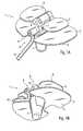
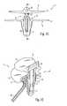
- FIGS. 1A to 1Cshow, in various schematic, perspective overall views, an exemplary embodiment of a ligament-tensioning device 1 designed according to the invention for a knee joint, which is hydraulically adjustable.
- the ligament-tensioning device 1comprises a first, distal abutment plate 2 and a second, proximal abutment plate 3.
- the abutment plates 2, 3are symmetrically formed in two parts and formed so that they can be brought into abutment on skeleton parts not shown. In the described embodiment, these are the skeletal parts of a knee joint.
- the first, distal abutment plate 2has a distal tibial bearing surface 4, which abuts against the bone section of the tibia (Tibia). It has a planar design and has an outer contour adapted to the shape of the tibial bone, which preferably terminates flush with the tibial bone at the edge.
- the second, proximal abutment plate 3has a proximal femoral abutment surface 5, which abuts against the condyles of the femur (femur).
- This onecan according to the roundish shape of the condyles have adapted, also rounded contour.
- the contact surface 5is smooth or even polished to allow an approximately frictionless movement of the femur on the contact surface.
- the second, proximal contact plate 3is smaller than the first, distal contact plate 2, since the contact surface of the femoral condyles is smaller than the contact surface of the tibial bone.
- the bearing plates 2, 3are interconnected by a base body 6, which has an anchoring pin 7.
- the ligament-tensioning device 1is anchored in the tibia.
- a bone cavityis introduced into the tibial bone, which receives the tibial part of a knee joint prosthesis during the further course of the operation in the case of the prosthetic restoration of a knee joint.
- the first, distal abutment plate 2is fixed to the base body 6, while the second, proximal abutment plate 3 is connected to the base body 6 via an axis 8, which allows tilting of the second, proximal abutment plate 3 relative to the first, distal abutment plate 2.
- the tilting movementtakes place in the frontal plane in varus-valgus direction.
- the jointcan move freely and unstrained despite strained ligament-tensioning device 1, when the bones are bent relative to each other. This is particularly important with regard to the preparation of the prosthetic restoration of a joint, since the overall situation of the ligamentous structures in the region of the joint, their number and tension must be examined before the implantation of a prosthesis.
- the base body 6comprises a hydraulic adjusting device 9, which allows a change in the position of the bearing plates 2, 3 to each other in the proximal-distal direction.
- the hydraulic actuator 9comprises, as shown in Fig. 1D, a supply line 10 through which the hydraulic medium is supplied.
- Hydraulic mediumis preferably a biocompatible fluid such as isotonic saline solution provided, since this causes no problems in the surgical field in case of leakage or breakage of the supply line 10.
- the hydraulic mediumis pressed under high pressure into the supply line 10 and actuates a arranged in the hydraulic actuator 9 in the anchoring pin 7 piston 11, which is in operative connection with the second, proximal contact plate 3.
- a guide pin 12is provided, which extends parallel to the piston 11 and is guided in a recess 13 of the base body 6.
- the piston 11acts upon application of pressure to the axis 8 and thereby displaces the second, proximal contact plate 3 in the proximal direction.
- the second, proximal contact plate 3moves back distally due to the tension of the ligaments.
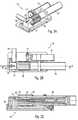
- the pressure required to act on the hydraulic ligament tensioning device 1is provided by a hydraulic unit (not shown) via a drive unit 14.
- the drive unit 14is shown in FIGS. 2A to 2C in different views. Only the components essential to the invention are explained.
- the drive unit 14may otherwise be constructed in a known manner.
- a stepper motor 15is arranged parallel to a shaft 16 of the hydraulic unit.
- a gear 17 of the stepping motor 15engages in a toothing 18 of the shaft 16 a. By the rotation of the gear 17 of the stepping motor 15, the shaft 16 of the hydraulic unit is driven.
- a pressure sensor 19 for the prevailing pressure in the hydraulic line 10 and a vent valve 20are provided.
- the hydraulic line 10is connected by means of a suitable connection 21 to the drive unit 14 and leads to the ligament-tensioning device 1.
- FIG. 2Cwhich is a section through the drive unit 14 shown in FIG. 2B along the line labeled II-II
- rotation of the shaft 16 of the hydraulic power unitwill cause a pin 22 disposed in the shaft 16 moved in an axial direction of the shaft 16.
- the pressure in a volume 23 filled with hydraulic mediumis increased or decreased depending on the direction of rotation.
- One or more sealing rings 24prevent the escape of the hydraulic medium.
- a biocompatible fluidsuch as isotonic saline or any other antiseptic rinse solution is suitable as the hydraulic medium.
- the pressure in the volume 23 filled with hydraulic mediumcan be arbitrarily and continuously increased or reduced, and the ligament-tensioning device 1 can thereby be clamped or relieved as desired.
- the pressure sensor 19 and / or by the integration of the inventively designed ligament-tensioning device 1the pressure values can be documented in a suitable manner.
- the documentation of the force associated with a specific pressure value and thus with a defined path of the piston 11 of the ligament-tensioning device 1 and a defined extension of the ligamentsmakes it possible to record a force-displacement diagram z. B. for the prosthetic to be treated joint in a flexion range between 0 ° and about 120 °.
- the tensile force exerted by the ligamentsmust behave constantly over the flexion area.
- conventional ligament-tensioning devices 1allow only the static spreading of the joint under a defined flexion angle, on the other hand the ligaments are displaced from their natural position by the attachment of the ligament-tensioning device 1, so that it is impossible to adjust the ligament tension when the ligament-tensioning device 1 is applied.
- both a flexion of the joint with applied ligament tensioning device 1is possible because the smooth or polished contact surface 5 of the second contact plate 3 allows a free adjustment of the bone position according to the respective Felxionslage, on the other hand, the ligaments are due the compact shape and the hydraulic actuation of the ligament tensioning device 1 in its natural position, since the hinge or the capsule capsule apparatus can be completely closed after inserting the ligament-tensioning device 1 down to a small opening through which the supply line 10 is guided , so that the preoperative situation can be restored except for small deviations. After the prosthetic restoration of the joint, individual ligaments can then be loosened directly to the extent necessary to achieve optimal mobility of the joint over the entire flexion area.
- the inventively designed ligament-tensioning device 1can by their special shape and operation to a detailed preparation for the prosthetic restoration with optimal approximation to the situation of an intact joint.
- the ligament-tensioning device according to the inventioncan be used not only on joints, but also on other skeletal parts, For example, also be used for spreading of vertebral bodies in disc surgery.
Landscapes
- Health & Medical Sciences (AREA)
- Life Sciences & Earth Sciences (AREA)
- Surgery (AREA)
- Heart & Thoracic Surgery (AREA)
- Engineering & Computer Science (AREA)
- Biomedical Technology (AREA)
- Nuclear Medicine, Radiotherapy & Molecular Imaging (AREA)
- Medical Informatics (AREA)
- Molecular Biology (AREA)
- Animal Behavior & Ethology (AREA)
- General Health & Medical Sciences (AREA)
- Public Health (AREA)
- Veterinary Medicine (AREA)
- Prostheses (AREA)
Description
Translated fromGermanDie Erfindung betrifft eine Bänderspannvorrichtung für Skelettteile, insbesondere Gelenke des menschlichen oder tierischen Körpers nach dem Oberbegriff des Anspruchs 1.The invention relates to a ligament-tensioning device for skeletal parts, in particular joints of the human or animal body according to the preamble of claim 1.
Aus der
Nachteilig an der aus der
Die
Der Erfindung liegt demnach die Aufgabe zugrunde, eine Bänderspannvorrichtung zu schaffen, die es ermöglicht, die Kapsel-Bandstrukturen eines prothetisch zu versorgenden Skelettteils, insbesondere Gelenkes, in natürlicher Position der Ligamente und Weichteilstrukturen anzuspannen.The invention is therefore based on the object to provide a ligament-tensioning device, which makes it possible to clamp the capsular ligament structures of a prosthetic skeletal part to be treated, in particular joint, in the natural position of the ligaments and soft tissue structures.
Die Aufgabe wird durch die Merkmale des Anspruchs 1 gelöst.The object is solved by the features of claim 1.
Erfindungsgemäß erfolgt die Spannung der Ligamente dabei über eine Bänderspannvorrichtung mit einer hydraulischen Stellvorrichtung. Dadurch läßt sich ein Kraft-Weg-Diagramm während der Operation vermessen, so daß die dabei gewonnenen Erkenntnisse in den weiteren Operationsablauf, insbesondere die Auswahl der Prothesenkomponenten, einfließen können. Der Druck des Hydraulikmediums ist dabei ein Maß für die Kraft. Das zugeführte Volumen des Hydraulikmediums ist dabei ein Maß für den Weg.According to the invention, the tension of the ligaments takes place via a ligament-tensioning device with a hydraulic adjusting device. As a result, a force-displacement diagram can be measured during the operation, so that the knowledge gained thereby can be incorporated into the further course of the operation, in particular the selection of the prosthesis components. The pressure of the hydraulic medium is a measure of the force. The supplied volume of the hydraulic medium is a measure of the way.
Die Bänderspannvorrichtung weist dabei eine erste und eine zweite Anlageplatte auf, welche an den jeweiligen Skelettteilen in Anlage gebracht werden und zueinander durch die hydraulische Stellvorrichtung in proximal-distaler Richtung verschieblich sind.The ligament-tensioning device has in this case a first and a second abutment plate, which are brought into abutment against the respective skeletal parts and are displaceable relative to each other by the hydraulic adjusting device in the proximal-distal direction.
Weiterhin sind die Anlageplatten durch einen Grundkörper miteinander verbunden, in welchem die hydraulische Stellvorrichtung angeordnet ist.Furthermore, the bearing plates are interconnected by a base body in which the hydraulic actuator is arranged.
Weitere vorteilhafte Ausgestaltungen der Erfindung sind in den Unteransprüchen gekennzeichnet.Further advantageous embodiments of the invention are characterized in the subclaims.
Besonders vorteilhaft ist die bewegliche Anordnung der zweiten Anlageplatte gegenüber der ersten Anlageplatte über eine anterio-posteriore Achse, welche eine Verkippung der zweiten Anlageplatte in Varus-Valgus-Richtung erlaubt.Particularly advantageous is the movable arrangement of the second abutment plate relative to the first abutment plate via an anterio-posterior axis, which allows tilting of the second abutment plate in varus-valgus direction.
Die glatte Oberfläche der zweiten Anlageplatte erlaubt vorteilhafterweise eine freie Bewegung des Femurknochens je nach Stellung des Gelenks und somit eine unverspannte Lage der Ligamente.The smooth surface of the second bearing plate advantageously allows a free movement of the femur depending on the position of the joint and thus an unstrained position of the ligaments.
Vorteilhafterweise ist die Krafteinleitung auf die hydraulische Stellvorrichtung über ein Hydraulikmedium, dessen Druck durch eine bekannte Antriebseinheit mit einem Schrittmotor stufenlos regelbar ist, in einfacher Weise möglich.Advantageously, the introduction of force to the hydraulic adjusting device via a hydraulic medium whose pressure is infinitely variable by a known drive unit with a stepping motor, in a simple manner possible.
Die Erfindung wird im folgenden anhand schematischer Darstellungen in verschiedenen Perspektiven näher erläutert.The invention is explained in more detail below with reference to schematic representations in different perspectives.
Es zeigen:
- Fig. 1A
- eine schematische, perspektivische Ansicht eines Ausführungsbeispiels einer erfindungsgemäßen Bänderspannvorrichtung in einer Ansicht von schräg oben,
- Fig. 1B
- eine schematische, perspektivische Ansicht des in Fig. 1A dargestellten Ausführungsbeispiels einer erfindungsgemäßen Bänderspannvorrichtung in einer Ansicht von schräg unten,
- Fig. 1C
- eine schematische Ansicht des in Fig. 1A dargestellten Ausführungsbeispiels einer erfindungsgemäßen Bänderspannvorrichtung in einer Ansicht von vorne,
- Fig. 1D
- eine schematische geschnittene Ansicht des in Fig. 1A dargestellten Ausführungsbeispiels einer erfindungsgemäßen Bänderspannvorrichtung in einer Ansicht von schräg oben auf die Schnittfläche und
- Fig. 2A-C
- schematische Ansichten und Schnitte einer für das in Fig. 1 dargestellte Ausführungsbeispiel einer erfindungsgemäßen Bänderspannvorrichtung geeigneten Antriebseinheit.
- Fig. 1A
- a schematic, perspective view of an embodiment of a ligament-tensioning device according to the invention in an oblique view from above,
- Fig. 1B
- 1 is a schematic, perspective view of the embodiment of a ligament-tensioning device according to the invention shown in FIG. 1A in a view obliquely from below,
- Fig. 1C
- 1 is a schematic view of the embodiment of a ligament-tensioning device according to the invention shown in FIG. 1A in a view from the front,
- Fig. 1D
- a schematic sectional view of the embodiment of a ligament-tensioning device according to the invention shown in Fig. 1A in a view obliquely from above on the cutting surface and
- Fig. 2A-C
- schematic views and sections of an illustrated for in Fig. 1 embodiment of a ligament-tensioning device according to the invention suitable drive unit.
Fig. 1A bis 1C zeigen in verschiedenen schematischen, perspektivischen Gesamtansichten ein Ausführungsbeispiel einer erfindungsgemäß ausgestalteten Bänderspannvorrichtung 1 für ein Kniegelenk, welche hydraulisch verstellbar ist.FIGS. 1A to 1C show, in various schematic, perspective overall views, an exemplary embodiment of a ligament-tensioning device 1 designed according to the invention for a knee joint, which is hydraulically adjustable.
Die Bänderspannvorrichtung 1 umfaßt dabei eine erste, distale Anlageplatte 2 und eine zweite, proximale Anlageplatte 3. Die Anlageplatten 2, 3 sind dabei symmetrisch zweiteilig ausgebildet und so ausgeformt, daß sie in Anlage an nicht weiter dargestellte Skelettteile gebracht werden können. Im beschriebenen Ausführungsbeispiel sind dies die Skelettteile eines Kniegelenks.The ligament-tensioning device 1 comprises a first,
Die erste, distale Anlageplatte 2 weist eine distale tibiale Anlagefläche 4 auf, welche an den Knochenschnitt des Schienbeins (Tibia) anliegt. Sie ist flächig ausgebildet und weist eine der Form des Schienbeinkopfes angepaßte Außenkontur auf, welche vorzugsweise randseitig bündig mit dem Schienbeinkopf abschließt.The first,
Entsprechend weist die zweite, proximale Anlageplatte 3 eine proximale femurale Anlagefläche 5 auf, welche an den Kondylen des Oberschenkels (Femur) anliegt. Diese kann entsprechend der rundlichen Form der Kondylen eine angepaßte, ebenfalls gerundete Kontur aufweisen. Die Anlagefläche 5 ist dabei glatt oder sogar poliert, um eine annähernd reibungsfreie Bewegung des Femurs an der Anlagefläche zu ermöglichen. Die zweite, proximale Anlageplatte 3 ist dabei kleiner als die erste, distale Anlageplatte 2, da die Anlagefläche der Femurkondylen kleiner ist als die Anlagefläche des Schienbeinkopfes.Correspondingly, the second,
Die Anlageplatten 2, 3 sind durch einen Grundkörper 6 miteinander verbunden, welcher einen Verankerungszapfen 7 aufweist. Mittels des Verankerungszapfens 7 wird die Bänderspannvorrichtung 1 in der Tibia verankert. Zu diesem Zweck wird bei der vorbereitenden Bearbeitung des Schienbeinkopfes in diesen eine Knochenkavität eingebracht, welche im weiteren Operationsverlauf bei der prothetischen Versorgung eines Kniegelenks den tibialen Teil einer Kniegelenksprothese aufnimmt.The bearing
Die erste, distale Anlageplatte 2 ist dabei an dem Grundkörper 6 fixiert, während die zweite, proximale Anlageplatte 3 mit dem Grundkörper 6 über eine Achse 8 verbunden ist, welche eine Verkippung der zweiten, proximalen Anlageplatte 3 gegenüber der ersten, distalen Anlageplatte 2 ermöglicht. Die Kippbewegung findet dabei in der Frontalebene in Varus-Valgus-Richtung statt. Dadurch kann sich das Gelenk frei und unverspannt trotz gespannter Bänderspannvorrichtung 1 bewegen, wenn die Knochen relativ zueinander gebeugt werden. Dies ist insbesondere in Hinblick auf die Vorbereitung der prothetischen Versorgung eines Gelenks wichtig, da die Gesamtsituation der ligamentären Strukturen im Bereich des Gelenks, ihre Anzahl und Spannung vor der Implantation einer Prothese untersucht werden muß.The first,
Weiterhin umfaßt der Grundkörper 6 erfindungsgemäß eine hydraulische Stellvorrichtung 9, welche eine Veränderung der Lage der Anlageplatten 2, 3 zueinander in proximal-distaler Richtung erlaubt. Die hydraulische Stellvorrichtung 9 umfaßt, wie aus Fig. 1D ersichtlich, eine Zuleitung 10, durch welche das Hydraulikmedium zugeleitet wird. Als Hydraulikmedium ist vorzugsweise ein biokompatibles Fluid wie z.B. isotonische Kochsalzlösung vorgesehen, da diese bei einer eventuellen Leckage oder beim Bruch der Zuleitung 10 keine Probleme im Operationsfeld verursacht.Furthermore, the
Das Hydraulikmedium wird unter hohem Druck in die Zuleitung 10 gepreßt und betätigt einen in der hydraulischen Stellvorrichtung 9 in dem Verankerungszapfen 7 angeordneten Kolben 11, welcher mit der zweiten, proximalen Anlageplatte 3 in Wirkverbindung steht. Um beim Aufspreizen der Anlageplatten 2, 3 eine korrekte Führung zu erhalten, ist ein Führungsstift 12 vorgesehen, welcher sich parallel zum Kolben 11 erstreckt und in einer Ausnehmung 13 des Grundkörpers 6 geführt ist. Der Kolben 11 wirkt bei Beaufschlagung mit Druck auf die Achse 8 ein und verschiebt dadurch die zweite, proximale Anlageplatte 3 in proximaler Richtung. Wird der Druck durch das Hydraulikmedium abgebaut, bewegt sich die zweite, proximale Anlageplatte 3 durch die Spannung der Ligamente in distaler Richtung zurück.The hydraulic medium is pressed under high pressure into the
Der für die Beaufschlagung der hydraulischen Bänderspannvorrichtung 1 benötigte Druck wird von einem nicht näher dargestellten Hydraulikaggregat über eine Antriebseinheit 14 zur Verfügung gestellt.The pressure required to act on the hydraulic ligament tensioning device 1 is provided by a hydraulic unit (not shown) via a
Die Antriebseinheit 14 ist in den Fig. 2A bis 2C in verschiedenen Ansichten dargestellt. Erläutert werden nur die erfindungswesentlichen Komponenten. Die Antriebseinheit 14 kann im übrigen in bekannter Weise aufgebaut sein.The
Ein Schrittmotor 15 ist dabei parallel zu einer Welle 16 des Hydraulikaggregats angeordnet. Ein Zahnrad 17 des Schrittmotors 15 greift in eine Verzahnung 18 der Welle 16 ein. Durch die Rotation des Zahnrads 17 des Schrittmotors 15 wird die Welle 16 des Hydraulikaggregats angetrieben.A
Weiterhin sind ein Drucksensor 19 für den in der Hydraulikleitung 10 herrschenden Druck sowie ein Entlüftungsventil 20 vorgesehen. Die Hydraulikleitung 10 ist mittels eines geeigneten Anschlusses 21 mit der Antriebseinheit 14 verbunden und führt zu der Bänderspannvorrichtung 1.Furthermore, a
Wie aus der geschnittenen Ansicht in Fig. 2C ersichtlich, welche einen Schnitt durch die in Fig. 2B dargestellte Antriebseinheit 14 entlang der mit II-II bezeichneten Linie darstellt, wird durch die Rotation der Welle 16 des Hydraulikaggregates ein in der Welle 16 angeordneter Stift 22 in einer Achsrichtung der Welle 16 bewegt. Dadurch wird der Druck in einem mit Hydraulikmedium gefüllten Volumen 23 je nach Drehrichtung erhöht oder verringert. Ein oder mehrere Dichtringe 24 verhindern das Austreten des Hydraulikmediums. Wie bereits weiter oben erwähnt, eignet sich als Hydraulikmedium ein biokompatibles Fluid wie beispielsweise isotonische Kochsalzlösung oder jede andere antiseptische Spüllösung.As can be seen in the sectional view in FIG. 2C, which is a section through the
Durch den stufenlosen Antrieb durch den Schrittmotor 15 kann der Druck in dem mit Hydraulikmedium gefüllten Volumen 23 beliebig und stufenlos erhöht oder verringert werden und die Bänderspannvorrichtung 1 dadurch beliebig aufgespannt oder entlastet werden. Durch den Drucksensor 19 und/oder durch die Einbindung der erfindungsgemäß ausgestalteten Bänderspannvorrichtung 1 können die Druckwerte in geeigneter Weise dokumentiert werden.Due to the stepless drive by the stepping
Die Dokumentation der mit einem bestimmten Druckwert und damit mit einem definierten Weg des Kolbens 11 der Bänderspannvorrichtung 1 sowie einer definierten Verlängerung der Ligamente verbundenen Kraft ermöglicht die Aufnahme eines Kraft-Weg-Diagramms z. B. für das prothetisch zu versorgende Gelenk in einem Flexionsbereich zwischen 0° und ca. 120°. Um eine optimale Anpassung des Ligamenteapparates an die zu implantierende Prothese bzw. an die nach der prothetischen Versorgung etablierte Situation zu ermöglichen, muß sich die durch die Ligamente ausgeübte Zugkraft über den Flexionsbereich konstant verhalten.The documentation of the force associated with a specific pressure value and thus with a defined path of the
Mittels der erfindungsgemäßen Bänderspannvorrichtung 1 kann ein dynamisches Kraft-Weg-Diagramm erstellt werden.By means of the ligament-tensioning device 1 according to the invention, a dynamic force-displacement diagram can be created.
Herkömmliche Bänderspannvorrichtungen 1 ermöglichen einerseits nur die statische Aufspreizung des Gelenks unter einem definierten Flexionswinkel, andererseits sind die Ligamente durch das Anbringen der Bänderspannvorrichtung 1 so aus ihrer natürlichen Lage verschoben, daß eine Einstellung der Bänderspannung bei applizierter Bänderspannvorrichtung 1 unmöglich ist.On the one hand, conventional ligament-tensioning devices 1 allow only the static spreading of the joint under a defined flexion angle, on the other hand the ligaments are displaced from their natural position by the attachment of the ligament-tensioning device 1, so that it is impossible to adjust the ligament tension when the ligament-tensioning device 1 is applied.
Im Gegensatz dazu ist durch die erfindungsgemäß ausgestaltete Bänderspannvorrichtung 1 sowohl eine Flexion des Gelenks bei applizierter Bänderspannvorrichtung 1 möglich, da die glatte oder polierte Anlagefläche 5 der zweiten Anlageplatte 3 eine freie Anpassung der Knochenposition gemäß der jeweiligen Felxionslage ermöglicht, andererseits befinden sich die Ligamente bedingt durch die kompakte Form und die hydraulische Betätigung der Bänderspannvorrichtung 1 in ihrer natürlichen Lage, da das Gelenk bzw. der Bänder-Kapsel-Apparat nach dem Einsetzen der Bänderspannvorrichtung 1 bis auf eine kleine Öffnung, durch welche die Zuleitung 10 geführt ist, vollständig geschlossen werden kann, so daß die präoperative Situation bis auf kleine Abweichungen wieder herstellbar ist. Nach der prothetischen Versorgung des Gelenks können dann einzelne Ligamente direkt im notwendigen Umfang gelöst werden, um eine optimale Beweglichkeit des Gelenks über den gesamten Flexionsbereich zu erzielen.In contrast, by the inventively designed ligament tensioning device 1 both a flexion of the joint with applied ligament tensioning device 1 is possible because the smooth or
Die erfindungsgemäß ausgestaltete Bänderspannvorrichtung 1 läßt durch ihre besondere Form und Betätigung eine detaillierte Vorbereitung auf die prothetische Versorgung mit optimaler Annäherung an die Situation eines intakten Gelenks zu.The inventively designed ligament-tensioning device 1 can by their special shape and operation to a detailed preparation for the prosthetic restoration with optimal approximation to the situation of an intact joint.
Die erfindungsgemäße Bänderspannvorrichtung kann nicht nur an Gelenken, sondern auch an anderen Skelettteilen, beispielsweise auch zum Spreizen von Wirbelkörpern bei Bandscheibenoperationen zum Einsatz kommen.The ligament-tensioning device according to the invention can be used not only on joints, but also on other skeletal parts, For example, also be used for spreading of vertebral bodies in disc surgery.
Claims (19)
- Ligament tensioning device (1) for activating the ligamentous and/or capsular apparatus while implanting a skeletal implant, with a first, distal bearing plate (2) for bearing against a first skeletal part and a second, proximal bearing plate (3) for bearing against a second skeletal part, wherein the first, distal bearing plate (2) can be displaced with respect to the second, proximal bearing plate (3) by a hydraulic actuating device (9),
characterised in
that the first bearing plate (2) and the second bearing plate (3) are connected together by a base body (6), in which the hydraulic actuating device (9) of the ligament tensioning device (1) is disposed. - Ligament tensioning device according to Claim 1,
characterised in
that the first bearing plate (2) is connected to the base body (6) in a fixed manner. - Ligament tensioning device according to Claim 2,
characterised in
that the second bearing plate (3) is connected to the base body (6) in a mobile manner via a pivot pin (8). - Ligament tensioning device according to Claim 3,
characterised in
that the second bearing plate (3) is disposed so as to be tiltable medially-laterally with respect to the first bearing plate (2). - Ligament tensioning device according to any one of Claims 1 to 4,
characterised in
that a tibial anchoring pin (7) is formed on the base body (6). - Ligament tensioning device according to any one of Claims 1 to 5,
characterised in
that the hydraulic actuating device (9) comprises a
plunger (11) which is disposed in the base body (6) and the anchoring pin (7). - Ligament tensioning device according to Claim 6,
characterised in
that the plunger (11) is actively connected to the second, proximal bearing plate (3). - Ligament tensioning device according to Claim 6 or 7,
characterised in
that a guide pin (12) which is parallel to the plunger (11) is guided in a recess (13) of the base body (6). - Ligament tensioning device according to any one of Claims 1 to 8,
characterised in
that the hydraulic actuating device (9) comprises a feed line (10). - Ligament tensioning device according to any one of Claims 1 to 9,
characterised in
that the hydraulic actuating device (9) is filled with a hydraulic medium. - Ligament tensioning device according to Claim 10,
characterised in
that a biocompatible solution serves as the hydraulic medium. - Ligament tensioning device according to Claim 10 or 11,
characterised in
that isotonic sodium chloride solution serves as the hydraulic medium. - Ligament tensioning device according to any one of Claims 10 to 12,
characterised in
that the pressure of the hydraulic medium on the plunger (11) can be steplessly adjusted by a drive unit (14). - Ligament tensioning device according to Claim 13,
characterised in
that the drive unit (14) comprises a stepping motor (15). - Ligament tensioning device according to Claim 14,
characterised in
that the stepping motor (15) drives a shaft (16) of a hydraulic unit via a gear wheel (17) and a tooth system (18). - Ligament tensioning device according to Claim 15,
characterised in
that a pin (22) is disposed in the shaft (16), through the axial displacement of which pin a volume (23) containing the hydraulic medium is steplessly enlarged or diminished. - Ligament tensioning device according to any one of Claims 13 to 16,
characterised in
that the drive unit (14) comprises a pressure sensor (19). - Ligament tensioning device according to any one of Claims 13 to 17,
characterised in
that the drive unit (14) comprises a connection (21) for a hydraulic line (10). - Ligament tensioning device according to any one of Claims 1 to 18,
characterised in
that the proximal bearing face (5) of the second, proximal bearing plate (3) has a smooth and/or polished surface.
Applications Claiming Priority (3)
| Application Number | Priority Date | Filing Date | Title |
|---|---|---|---|
| DE10340885 | 2003-09-04 | ||
| DE10348585ADE10348585A1 (en) | 2003-09-04 | 2003-10-20 | Hydraulic ligament tensioning device |
| PCT/EP2004/009645WO2005023120A1 (en) | 2003-09-04 | 2004-08-30 | Hydraulic ligament-tensioning device |
Publications (2)
| Publication Number | Publication Date |
|---|---|
| EP1659955A1 EP1659955A1 (en) | 2006-05-31 |
| EP1659955B1true EP1659955B1 (en) | 2007-10-17 |
Family
ID=34276537
Family Applications (1)
| Application Number | Title | Priority Date | Filing Date |
|---|---|---|---|
| EP04764613AExpired - LifetimeEP1659955B1 (en) | 2003-09-04 | 2004-08-30 | Hydraulic ligament-tensioning device |
Country Status (3)
| Country | Link |
|---|---|
| EP (1) | EP1659955B1 (en) |
| DE (1) | DE502004005284D1 (en) |
| WO (1) | WO2005023120A1 (en) |
Families Citing this family (16)
| Publication number | Priority date | Publication date | Assignee | Title |
|---|---|---|---|---|
| US7615055B2 (en)* | 2005-03-31 | 2009-11-10 | Depuy Products, Inc. | Method and apparatus for use in balancing ligaments of a knee |
| US8635082B2 (en) | 2006-05-25 | 2014-01-21 | DePuy Synthes Products, LLC | Method and system for managing inventories of orthopaedic implants |
| US8197489B2 (en) | 2008-06-27 | 2012-06-12 | Depuy Products, Inc. | Knee ligament balancer |
| US8551023B2 (en) | 2009-03-31 | 2013-10-08 | Depuy (Ireland) | Device and method for determining force of a knee joint |
| US8597210B2 (en) | 2009-03-31 | 2013-12-03 | Depuy (Ireland) | System and method for displaying joint force data |
| US8721568B2 (en) | 2009-03-31 | 2014-05-13 | Depuy (Ireland) | Method for performing an orthopaedic surgical procedure |
| US8556830B2 (en) | 2009-03-31 | 2013-10-15 | Depuy | Device and method for displaying joint force data |
| US8740817B2 (en) | 2009-03-31 | 2014-06-03 | Depuy (Ireland) | Device and method for determining forces of a patient's joint |
| GB201115411D0 (en) | 2011-09-07 | 2011-10-19 | Depuy Ireland | Surgical instrument |
| US9381011B2 (en) | 2012-03-29 | 2016-07-05 | Depuy (Ireland) | Orthopedic surgical instrument for knee surgery |
| US10206792B2 (en) | 2012-03-31 | 2019-02-19 | Depuy Ireland Unlimited Company | Orthopaedic surgical system for determining joint forces of a patients knee joint |
| US9545459B2 (en) | 2012-03-31 | 2017-01-17 | Depuy Ireland Unlimited Company | Container for surgical instruments and system including same |
| US10070973B2 (en) | 2012-03-31 | 2018-09-11 | Depuy Ireland Unlimited Company | Orthopaedic sensor module and system for determining joint forces of a patient's knee joint |
| US10098761B2 (en) | 2012-03-31 | 2018-10-16 | DePuy Synthes Products, Inc. | System and method for validating an orthopaedic surgical plan |
| US12433656B2 (en) | 2019-03-29 | 2025-10-07 | Depuy Ireland Unlimited Company | Methods, surgical instruments, and associated systems for performing a surgical procedure to balance a patient's knee |
| US11344352B2 (en) | 2019-03-29 | 2022-05-31 | Depuy Ireland Unlimited Company | Methods of operating a surgical instrument and performing a surgical procedure to balance a patient's knee |
Family Cites Families (5)
| Publication number | Priority date | Publication date | Assignee | Title |
|---|---|---|---|---|
| US6022377A (en)* | 1998-01-20 | 2000-02-08 | Sulzer Orthopedics Inc. | Instrument for evaluating balance of knee joint |
| DE29910761U1 (en)* | 1999-06-19 | 2000-11-23 | Mathys Medizinaltechnik Ag, Bettlach | Ligament tensioning device for non-spherical joints |
| NL1018438C1 (en)* | 2001-07-02 | 2003-01-08 | Baat Medical Engineering B V | Foldable and foldable tools for placement in a spine. |
| FR2840189B1 (en)* | 2002-05-30 | 2005-03-11 | Jean Pierre Gemon | HYDRAULIC RETRACTOR |
| DE20310289U1 (en)* | 2003-07-04 | 2003-09-04 | Aesculap AG & Co. KG, 78532 Tuttlingen | Device for filling a hydraulically distensible backbone vertebrae distracter with a hydraulic medium comprises a hand- controlled piston-cylinder arrangement that allows very fine and sensitive control of the fluid injection force |
- 2004
- 2004-08-30EPEP04764613Apatent/EP1659955B1/ennot_activeExpired - Lifetime
- 2004-08-30WOPCT/EP2004/009645patent/WO2005023120A1/enactiveIP Right Grant
- 2004-08-30DEDE502004005284Tpatent/DE502004005284D1/ennot_activeExpired - Lifetime
Also Published As
| Publication number | Publication date |
|---|---|
| DE502004005284D1 (en) | 2007-11-29 |
| EP1659955A1 (en) | 2006-05-31 |
| WO2005023120A1 (en) | 2005-03-17 |
Similar Documents
| Publication | Publication Date | Title |
|---|---|---|
| EP1659955B1 (en) | Hydraulic ligament-tensioning device | |
| DE10393182B4 (en) | Knee prosthesis with graft ligaments | |
| EP1519686B1 (en) | Ligament tensing device with displaceable lug | |
| EP1786369B1 (en) | Surgical instrument | |
| DE69317283T2 (en) | INSTRUMENTS FOR PREPARING THE FEMUR FOR AN ARTIFICIAL KNEE IMPLANT AND FOR POSITIONING THE FEMORAL IMPLANT | |
| DE19619093B4 (en) | Intramedullary nail system for fracture healing or bone extension | |
| DE69924193T2 (en) | INSTRUMENT FOR EVALUATING THE BALANCE OF A KNEE | |
| DE69311594T2 (en) | Adjustable tibial cutting guide in terms of rotation and angle | |
| DE69517296T2 (en) | DEVICE FOR RESECTING CONDIES OF A KNEE FOR INSERTING A KNEE PROSTHESIS | |
| EP0913132B1 (en) | Knee prosthesis | |
| DE4039064C2 (en) | ||
| DE69518077T3 (en) | CUTTER FOR THE FEMORAL INTERCONDYLARINE GROOVE OF A KNEE PROSTHESIS STABILIZED FROM THE BACK | |
| EP1187556B1 (en) | Ligament-tensioning device for non-spheroid joints | |
| EP0919195A1 (en) | Tool assembly for a prosthetic knee | |
| EP0928172A1 (en) | Shankless knee joint endoprosthesis | |
| EP0444197A1 (en) | Endoprosthesis of the hip joint | |
| EP2826445A1 (en) | Knee spacer system with adjustable spacer | |
| DE69821080T2 (en) | Device for cutting the femur to insert a knee prosthesis | |
| EP1645229B1 (en) | System for determining the ligament force | |
| DE202004014119U1 (en) | Surgical instrument to determine the size and/or height of a spinal disk implant, between neighboring vertebra in a human/animal spine, has test implant laying units at angles on holders for use with a variety of disks | |
| EP4282346B1 (en) | Surgical instrument | |
| WO2010003256A1 (en) | Device for simulating hip joint replacement operations | |
| EP1086667B1 (en) | Tibial element for a knee prothesis and modular set comprising this tibial element | |
| DE10348585A1 (en) | Hydraulic ligament tensioning device | |
| EP1108403B1 (en) | Assembly set for a knee prosthesis |
Legal Events
| Date | Code | Title | Description |
|---|---|---|---|
| PUAI | Public reference made under article 153(3) epc to a published international application that has entered the european phase | Free format text:ORIGINAL CODE: 0009012 | |
| 17P | Request for examination filed | Effective date:20060113 | |
| AK | Designated contracting states | Kind code of ref document:A1 Designated state(s):CH DE LI | |
| DAX | Request for extension of the european patent (deleted) | ||
| RBV | Designated contracting states (corrected) | Designated state(s):CH DE LI | |
| GRAP | Despatch of communication of intention to grant a patent | Free format text:ORIGINAL CODE: EPIDOSNIGR1 | |
| GRAS | Grant fee paid | Free format text:ORIGINAL CODE: EPIDOSNIGR3 | |
| GRAA | (expected) grant | Free format text:ORIGINAL CODE: 0009210 | |
| AK | Designated contracting states | Kind code of ref document:B1 Designated state(s):CH DE LI | |
| REG | Reference to a national code | Ref country code:CH Ref legal event code:NV Representative=s name:SPIERENBURG & PARTNER AG, PATENT- UND MARKENANWAEL Ref country code:CH Ref legal event code:EP | |
| REF | Corresponds to: | Ref document number:502004005284 Country of ref document:DE Date of ref document:20071129 Kind code of ref document:P | |
| PLBE | No opposition filed within time limit | Free format text:ORIGINAL CODE: 0009261 | |
| STAA | Information on the status of an ep patent application or granted ep patent | Free format text:STATUS: NO OPPOSITION FILED WITHIN TIME LIMIT | |
| 26N | No opposition filed | Effective date:20080718 | |
| PGFP | Annual fee paid to national office [announced via postgrant information from national office to epo] | Ref country code:CH Payment date:20080825 Year of fee payment:5 | |
| REG | Reference to a national code | Ref country code:CH Ref legal event code:PL | |
| PG25 | Lapsed in a contracting state [announced via postgrant information from national office to epo] | Ref country code:CH Free format text:LAPSE BECAUSE OF NON-PAYMENT OF DUE FEES Effective date:20090831 Ref country code:LI Free format text:LAPSE BECAUSE OF NON-PAYMENT OF DUE FEES Effective date:20090831 | |
| PGFP | Annual fee paid to national office [announced via postgrant information from national office to epo] | Ref country code:DE Payment date:20101029 Year of fee payment:7 | |
| REG | Reference to a national code | Ref country code:DE Ref legal event code:R119 Ref document number:502004005284 Country of ref document:DE Effective date:20120301 | |
| PG25 | Lapsed in a contracting state [announced via postgrant information from national office to epo] | Ref country code:DE Free format text:LAPSE BECAUSE OF NON-PAYMENT OF DUE FEES Effective date:20120301 |