EP1659936B1 - Apparatus and method for cordless recording and telecommunication transmission of three special ecg leads and their processing - Google Patents
Apparatus and method for cordless recording and telecommunication transmission of three special ecg leads and their processingDownload PDFInfo
- Publication number
- EP1659936B1 EP1659936B1EP04785415AEP04785415AEP1659936B1EP 1659936 B1EP1659936 B1EP 1659936B1EP 04785415 AEP04785415 AEP 04785415AEP 04785415 AEP04785415 AEP 04785415AEP 1659936 B1EP1659936 B1EP 1659936B1
- Authority
- EP
- European Patent Office
- Prior art keywords
- patient
- integrated
- ecg
- disposed
- recording
- Prior art date
- Legal status (The legal status is an assumption and is not a legal conclusion. Google has not performed a legal analysis and makes no representation as to the accuracy of the status listed.)
- Expired - Lifetime
Links
- 238000000034methodMethods0.000titleclaimsabstractdescription51
- 230000005540biological transmissionEffects0.000titleabstractdescription13
- 238000012545processingMethods0.000titleabstractdescription7
- 230000001413cellular effectEffects0.000claimsabstractdescription10
- 239000011159matrix materialSubstances0.000claimsdescription28
- 238000005259measurementMethods0.000claimsdescription12
- 238000004891communicationMethods0.000claimsdescription7
- 230000008569processEffects0.000abstractdescription8
- 230000009466transformationEffects0.000description19
- 238000004364calculation methodMethods0.000description10
- 230000000694effectsEffects0.000description8
- 230000005236sound signalEffects0.000description6
- 239000013598vectorSubstances0.000description4
- 208000010125myocardial infarctionDiseases0.000description3
- 238000013459approachMethods0.000description2
- 230000008859changeEffects0.000description2
- 208000029078coronary artery diseaseDiseases0.000description2
- 238000010586diagramMethods0.000description2
- 208000019622heart diseaseDiseases0.000description2
- 230000005405multipoleEffects0.000description2
- 230000004913activationEffects0.000description1
- 230000008901benefitEffects0.000description1
- 230000000747cardiac effectEffects0.000description1
- 238000010276constructionMethods0.000description1
- 208000037265diseases, disorders, signs and symptomsDiseases0.000description1
- 208000035475disorderDiseases0.000description1
- 238000004070electrodepositionMethods0.000description1
- 230000008030eliminationEffects0.000description1
- 238000003379elimination reactionMethods0.000description1
- 230000006872improvementEffects0.000description1
- 230000005923long-lasting effectEffects0.000description1
- 238000012986modificationMethods0.000description1
- 230000004048modificationEffects0.000description1
- 208000031225myocardial ischemiaDiseases0.000description1
- 210000004165myocardiumAnatomy0.000description1
- 210000000056organAnatomy0.000description1
- 230000009467reductionEffects0.000description1
- 230000004044responseEffects0.000description1
- 230000033764rhythmic processEffects0.000description1
- 238000001228spectrumMethods0.000description1
- 230000006641stabilisationEffects0.000description1
- 238000011105stabilizationMethods0.000description1
- 208000024891symptomDiseases0.000description1
Images

Classifications
- A—HUMAN NECESSITIES
- A61—MEDICAL OR VETERINARY SCIENCE; HYGIENE
- A61B—DIAGNOSIS; SURGERY; IDENTIFICATION
- A61B5/00—Measuring for diagnostic purposes; Identification of persons
- A61B5/0002—Remote monitoring of patients using telemetry, e.g. transmission of vital signals via a communication network
- A61B5/0004—Remote monitoring of patients using telemetry, e.g. transmission of vital signals via a communication network characterised by the type of physiological signal transmitted
- A61B5/0006—ECG or EEG signals
- A—HUMAN NECESSITIES
- A61—MEDICAL OR VETERINARY SCIENCE; HYGIENE
- A61B—DIAGNOSIS; SURGERY; IDENTIFICATION
- A61B5/00—Measuring for diagnostic purposes; Identification of persons
- A61B5/24—Detecting, measuring or recording bioelectric or biomagnetic signals of the body or parts thereof
- A61B5/30—Input circuits therefor
- A61B5/307—Input circuits therefor specially adapted for particular uses
- A61B5/308—Input circuits therefor specially adapted for particular uses for electrocardiography [ECG]
- A—HUMAN NECESSITIES
- A61—MEDICAL OR VETERINARY SCIENCE; HYGIENE
- A61B—DIAGNOSIS; SURGERY; IDENTIFICATION
- A61B5/00—Measuring for diagnostic purposes; Identification of persons
- A61B5/24—Detecting, measuring or recording bioelectric or biomagnetic signals of the body or parts thereof
- A61B5/316—Modalities, i.e. specific diagnostic methods
- A61B5/318—Heart-related electrical modalities, e.g. electrocardiography [ECG]
- A61B5/332—Portable devices specially adapted therefor
- A—HUMAN NECESSITIES
- A61—MEDICAL OR VETERINARY SCIENCE; HYGIENE
- A61B—DIAGNOSIS; SURGERY; IDENTIFICATION
- A61B2560/00—Constructional details of operational features of apparatus; Accessories for medical measuring apparatus
- A61B2560/04—Constructional details of apparatus
- A61B2560/0462—Apparatus with built-in sensors
- A61B2560/0468—Built-in electrodes
- A—HUMAN NECESSITIES
- A61—MEDICAL OR VETERINARY SCIENCE; HYGIENE
- A61B—DIAGNOSIS; SURGERY; IDENTIFICATION
- A61B5/00—Measuring for diagnostic purposes; Identification of persons
- A61B5/24—Detecting, measuring or recording bioelectric or biomagnetic signals of the body or parts thereof
- A61B5/30—Input circuits therefor
Definitions
- the present inventionis related to the field of medical electronics, more precisely to the field of instruments for measuring and recording bioelectric signals, such as electrocardiographs. It concerns devices for data acquisition, processing, and transmission via commercial telecommunication network.
- the inventionis categorized within the A61B 5/00 class, which defines methods or devices for measurement or recording in diagnostics purposes. More specifically, the invention is categorized within the A61 B 5/04 class, which defines instruments for measuring or recording bioelectric charges of a body or an organ, such as electrocardiographs.
- the inventionresolves the construction problem of the device and procedure for cordless recording, telecommunication transmission, and processing of three special ECG leads. It implies the use of a mobile pocket device with integrated electrodes, three of which are connected to the active inputs of the amplifier coupled to the control module, one of which is passive, and one connected to the ground.
- the inventionwith precisely defined procedure for recording, transmission and processing, enables quick, simple, and accurate cordless self-recording (by the patient himself) with the device, transmission of three ECG leads, and obtaining of standard 12-lead ECG recording.
- the 12-lead ECG recordingwill be reconstructed with the satisfying accuracy, and the possibility for an error due to the incorrect positioning of the electrodes will be excluded as well as the possibility for a major diagnostic error due to so called base line wandering of the ECG signal during recording.
- the application of the devicewill be enabled within the widest spectrum of heart diseases with diagnoses of cardiac ischemia (Coronary Artery Disease - CAD).
- the conventional ECG leads V( D 1 , D 2 , D 3 , aVR, aVL, aVF.
- V 1 , V 2 , V 3 , V 4 , V 5 , V 6 )are obtained by multiplying the transformation matrix T with the recorded signals at the special leads V s ( V s 1 , V s 2 , V s 3 ).
- the universal transformation matrix for all patientsdoes not contain information about individual characteristics of a patient, which results in major errors in the reconstruction of the standard ECG lead signals.
- the inventionpresents the method and device for cordless recording, telecommunication transmission, and processing of three special ECG leads.
- the recording of three special ECG leadsis performed with the mobile device with strictly defined arrangement of integrated electrodes and the way of recording, which, after the transmission to a remote PC computer, enables the precise reconstruction of all 12 signals of standard ECG leads. In this way, the simplicity of use of the device with integrated electrodes is combined with high recording accuracy, until now possible only with the devices using cables for recording.
- the systemconsists of the stationary diagnostic callibration center and the mobile ECG device with integrated electrodes.
- the diagnostic callibration centercomprises a PC computer with the corresponding software, connected to a cellular telephone and a callibration ECG device with 14 electrodes.
- the calibration deviceis used for simultaneous recording of patient's 12 standard and three special ECG leads.
- the recording of special leadsis performed in a way which a patient will use himself while recording with the mobile ECG device with integrated electrodes.
- the transformation matrix of a patientis calculated and stored into a database.
- the obtained matrixis used for calculation of 12 standard ECG leads every time the patient sends, via telephone, the recording of three special leads taken by himself using the mobile ECG device with integrated electrodes.
- the accuracy in the reconstruction of 12 standard ECG leads using the recordings of three special leadsis achieved by strictlly defined arrangement of integrated electrodes in the mobile device and by the special way of recording.
- the reconstruction algorithmis based on the assumption that diffused electrical activity of the heart muscle can be approximated by a time-changing electrical dipole (heart dipole) immersed in a low conducting environment.
- Heart dipoleis a vector defined by three non-coplanar projections, so that it can be determined on the basis of recording of electric potential in any three points corresponding to three non-coplanar directions, i. e. three ECG leads not laying on the same plane. Once the heart vector is determined, it is easy to calculate the electric potentials in any point, meaning the 12 standard ECG leads as well.
- the system of reconstruction of the standard ECG leads on the basis of recording of three special leadsis based on the dipole representation of heart electrical activity.
- the heart dipoleis only the first term in the multipole expansion of diffused heart electrical activity and this approximation is valid only for recording points at the sufficient distance from the heart.
- the potentialis significantly affected by the non-dipole content created due to the presence of higher order terms in multipole expansion.
- the mobile ECG deviceis designed in such a way that two integrated electrodes could be touched with the fingers of the left and right hand, while two electrodes are simultaneously in contact with the patient's chest.
- the patient's handsare used as flexible elements for moving two recording points away from the heart (as the source of the electrical activity), using the electrode in contact with a finger of the right hand as the reference point for the recording of all three special leads.
- the electrodes in electrical contact with the patient's chestare set in the precisely defined position within the limited area on the patient's chest. By arranging the electrodes positions in this way, and choosing the reference point, the optimal minimization of the model errors (a) and transformation matrix calculation errors (b) has been achieved.
- An additional problem in signal recording of special as well as of standard ECG leadsis the effect of the base line wandering of the recorded signals.
- the problemoccurs during the recording of ECG signals with all kinds of ECG devices, but is more prominent with mobile ECG devices due to the more difficult recording conditions, especially with the devices intended for patient's recording of his own ECG.
- the elimination of the base line wandering problem during recording of special leadsis extremely important for the proper functioning of the system.
- This inventionestablishes the control of the base line wandering during recording of special leads with a mobile ECG device with integrated electrodes by the means of digital control module which controls and manages the process of recording automatically.
- a characteristic sound signalis being emitted.
- another characteristic sound signalis being emitted, informing a patient that the recording will start soon.
- the recording itselfis indicated by the third characteristic sound signal. If the significant base line wandering occurs in any phase of the procedure, the procedure will be repeated from the beginning. Doing so, the patient is enabled to send the high-quality recording of special leads, which makes possible the accurate reconstruction of standard ECG leads.
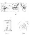
- Fig. 1shows the scheme of a device for recording three special ECG leads with the mobile ECG device 1 and their transmission to the diagnostic-calibration center 2 where, on the basis of the received special leads, computational reconstruction of standard ECG leads is performed. In order to realize the said reconstruction, it is necessary to determine corresponding reconstruction parameters for each patient by previous calibration. Recording of three special leads in urgent situation is performed by the patient 3 with the mobile device 1. The patient sends the memorized data into the diagnostic-calibration center 2 by means of a cellular telephone 4 that is connected to the mobile device I with the communication cable 5. There are sound and light indicators that help the patient to monitor the process of recording and sending the data.
- the diagnostic-calibration center 2is equipped with a PC computer 6 containing the suitable software, connected to the receiving cellular telephone 7 and the calibration ECG device 8 with 14 electrodes. Ten electrodes are grouped into the standard 12-lead ECG cable, while the remaining four are used for recording of three special ECG leads and are grouped into the separate box 9 with integrated electrodes arranged in the exactly same way as the electrodes in the mobile device 1.
- the data transmission via cellular telephones 4 and 7is shown, but the method itself will not be changed if the data transmission is performed by fixed telephone line with the help of a modem or if cordless communication is used instead of the cable 5 for communication between the mobile device 1 and the cellular telephone 4.
- the first stepcomprises simultaneous recording of 12 standard and three special ECG leads with the calibration device
- the reconstruction parametersare determined by the corresponding software on the PC computer 6.
- the software for calculation of parametersis based on the application of the least-squares deviation method.
- the reconstruction parametersare organized as a transformation matrix and they define a linear transformation between standard and special ECG leads. Transformation matrix for each patient is calculated separately and stored into a database in memory of the PC computer 6. Later, with the help of the software on the PC computer 6, this matrix is used for reconstruction of 12 standard ECG leads on the basis of three special leads recorded by the patient himself in the urgent situation and sent to the diagnostic-calibration center 2 via the cellular telephone 4.
- the software on the PC computer 6enables the display of the reconstructed ECG leads on the computer monitor and/or a printer.
- the electrodes on the box 9 connected to the calibration device 8are arranged identically as the electrodes in the mobile device 1. It is also necessary that the positions of the electrodes on the patient's body during the calibration are identical to the positions of the electrodes during the recording using the mobile device in urgent situation.
- the scheme of the arrangement of integrated electrodes in the mobile ECG device Iis given in Fig. 2.
- the push-button 10 on the front side of the deviceis used for activation of the recording and the process of sending the data.
- the positioning of the mobile ECG device 1 onto the chest of the patient 3 and the recording procedureare shown in Fig. 3.
- the deviceis positioned vertically onto the patient's chest so that the electrodes C, D, and E touch the patient's chest simultaneously.
- the deviceis held with a right hand finger on the electrode A, and a left hand finger on the electrode B.
- the electrical part of the deviceconsists of the amplifier module 11 and the digital control module 12.
- the amplifier module 11contains three amplifiers (111, 112, and 113) for amplifying the signals of three special leads.
- the electrode Ain electrical contact with the right hand, is connected in such a way that it represents the common reference point for all three amplifiers, i. e. recording leads.
- the electrodes B, C, and Dare connected to the active recording points of the amplifiers 111, 112, and 113.
- the electrode Eis connected to the common ground of all three amplifiers.
- the electrode Arepresents the reference (passive) point for recording the potentials of the remaining electrodes B, C, and D.
- the positions of the special leads recording points on the patient's bodyare the same in the calibration process and during the recording on the basis of which the reconstruction is performed.
- the arrangement of electrodes on the mobile device 1, given in Fig. 2be the same as the arrangement of electrodes on the box 9 of the calibration device.
- the recording procedure shown in Fig. 3be performed in the same way while using the mobile device 1 and while using the calibration device 8, that is, while positioning the recording electrodes of the box 9.
- the arrangement of the electrodes A and B on the front side of the devicecan be arbitrary, while it is necessary that they be used as presented in Fig. 3 (A - right hand, B - left hand).
- the position of the electrode Ecan be arbitrary or its use can be avoided if the electric scheme is solved in a different way.
- the common ground of the remaining amplifiers of the calibration devicewhich is conventionally positioned on the patient's right leg, can be used instead of the electrode E.
- the position of the active electrodes (C and D), providing the electrical contact with the patient's chest,is vital for the proper functioning of the whole system. Illustration of the position of active electrodes is shown in Fig. 5. Active electrodes C and D are positioned onto the patient's chest in the area between the left 13 and the right 14 mamilar line ( linea mamillaris ). These electrodes should lie on the direction that, with the direction of the medial line ( linea mediana anterior ), makes the angle ⁇ ranging from 30° to 90° (Fig. 6).
- the position of the electrode Ewhich represents the common ground, can be arbitrary, but it is convenient to choose it in such a way that it provides the mechanical stability of the mobile ECG device while in recording position, held against the patient's chest.
- the operating of the amplifier module 11 of the mobile device Iis controlled and managed with the digital control module 12. From the moment of putting the mobile device 1 in the recording position, the control module 12 checks the signal level at the output of the amplifiers 111, 112, and 113. As long as the signal level is out of the specified operating range of ⁇ 2.5mV, the characteristic sound signal, which the patient can easily memorize, is being emitted. From the moment when the signal level fits into the said operating range, another characteristic sound signal is being emitted for the following five seconds. This signal informs the patient that the recording will start soon. This recording delay period (five seconds) is approximately determined by the time constant of the amplified signal stabilization and depends on the frequency response of the amplifier. The third characteristic sound signal indicates the recording process itself.
- the digital control module 12detects the event and the whole procedure is repeated from the beginning.
- the procedure of controlling the recording processenables the patient to perform a high-quality recording of special leads, thus enabling the accurate reconstruction of standard ECG leads.
- the way of recording described above, electrode arrangement and their positioning, and control procedure of recordingprovide the conditions for highly accurate reconstruction of standard 12 ECG leads.
- the inventioncombines the simplicity in use of a device with integrated electrodes with high precision of the devices using cables for recording.
Landscapes
- Health & Medical Sciences (AREA)
- Life Sciences & Earth Sciences (AREA)
- Engineering & Computer Science (AREA)
- Surgery (AREA)
- General Health & Medical Sciences (AREA)
- Veterinary Medicine (AREA)
- Biophysics (AREA)
- Pathology (AREA)
- Biomedical Technology (AREA)
- Heart & Thoracic Surgery (AREA)
- Medical Informatics (AREA)
- Molecular Biology (AREA)
- Public Health (AREA)
- Animal Behavior & Ethology (AREA)
- Physics & Mathematics (AREA)
- Cardiology (AREA)
- Physiology (AREA)
- Computer Networks & Wireless Communication (AREA)
- Measurement And Recording Of Electrical Phenomena And Electrical Characteristics Of The Living Body (AREA)
- Accommodation For Nursing Or Treatment Tables (AREA)
- Measuring And Recording Apparatus For Diagnosis (AREA)
- Mobile Radio Communication Systems (AREA)
- Reduction Or Emphasis Of Bandwidth Of Signals (AREA)
- Heat Sensitive Colour Forming Recording (AREA)
- Input Circuits Of Receivers And Coupling Of Receivers And Audio Equipment (AREA)
Abstract
Description
- The present invention is related to the field of medical electronics, more precisely to the field of instruments for measuring and recording bioelectric signals, such as electrocardiographs. It concerns devices for data acquisition, processing, and transmission via commercial telecommunication network. According to the International Patent Classification (IPC), the invention is categorized within the A61B 5/00 class, which defines methods or devices for measurement or recording in diagnostics purposes. More specifically, the invention is categorized within the A61 B 5/04 class, which defines instruments for measuring or recording bioelectric charges of a body or an organ, such as electrocardiographs.
- The invention resolves the construction problem of the device and procedure for cordless recording, telecommunication transmission, and processing of three special ECG leads. It implies the use of a mobile pocket device with integrated electrodes, three of which are connected to the active inputs of the amplifier coupled to the control module, one of which is passive, and one connected to the ground. The invention, with precisely defined procedure for recording, transmission and processing, enables quick, simple, and accurate cordless self-recording (by the patient himself) with the device, transmission of three ECG leads, and obtaining of standard 12-lead ECG recording. During this process, the 12-lead ECG recording will be reconstructed with the satisfying accuracy, and the possibility for an error due to the incorrect positioning of the electrodes will be excluded as well as the possibility for a major diagnostic error due to so called base line wandering of the ECG signal during recording. Thus, the application of the device will be enabled within the widest spectrum of heart diseases with diagnoses of cardiac ischemia (Coronary Artery Disease - CAD).
- The concept of the system for urgent cardiac diagnostics which enables a patient, wherever he may be, to record his ECG himself and send it to his cardiologist in the remote diagnostic center via commercial telecommunication network (cellular or fixed telephone line) is well known. Namely, on the bases of the received ECG and the conversation with the patient, the cardiologist on duty can decide: a) whether an urgent intervention is needed, b) whether the intervention can be performed by the patient himself, or c) whether the patient's state requires urgent medical intervention, and acts accordingly. It is very important that the most critical period, from the occurrence of the first symptoms until the medical treatment, be minimized (Lenfant C. et al.: Considerations for a national heart attack alert program, Clin. Cardiol. 1990 Aug; 13 (8 Suppl 8): VIII9-11). There is a number of patents and products which, within the said contept of urgent cardiological diagnostics, offer different solutions for recording and transmitting the ECG signal:
U.S. Patent No. 4,889,134 Greenwold, et al., 1989;U.S. Patent No. 5,226,431 Bible, et al. 1993;U.S. Patent No. 5,321,618 Gessman, 1994;U.S. Patent No. 5,966,692 Langer, et al., 1999; PCTWO 01/70105 A2 - 1) The first group comprises solutions for sending the recording of one or two standard ECG leads. The mobile recorders of this group can be very small and with integrated electrodes (no cables are needed), which is the advantage of the group. The recording is performed by simple holding of the device on the patient's chest or by positioning the fingers on the integrated electrodes. This is a quick and simple way for a patient to record one or two leads of his ECG. However, recording one or two ECG signals limits the application of these devices to the patients with rhythm disorders, which is about 20% of the patient population with heart diseases. Typical device of this group is "CardioCall Event Recorder" by REYNOLDS MEDICAL.
- 2) The second group consists of solutions that enable direct recording and transmission of standard 12-lead ECG, thus including their application to the patients with the diagnoses of coronary artery diseases. Namely, in such patients, the complete standard 12-lead ECG is necessary for urgent diagnostics. Some of these devices are equipped with the full set of electrodes and cables for recording all 12 standard ECG leads (usually 10 electrodes, that is cables), which a patient himself attaches onto his body during recording. The typical representative of this group is "12 Lead Memory ECG Recorder" by TELESCAN MEDICAL SYSTEMS. The other method is the use of a reduced number of electrodes that are moved during the recording. For example, if four electrodes are used, three are positioned at the locations of standard ECG leads I, II, and III (arms and legs of the patient), while the fourth electrode has to be moved during recording to each of the six chest positions for recording chest leads V1-V6 (
US Patent No. 4,889,134, Greenwold et al., 1989 ). The method that uses three cable connected electrodes and four button-shaped integrated electrodes can be found in the device "Heartwiev P-12" by AEROTEL. The recording of 12 leads is performed in three steps: leads D1, D2, D3, aVR, aVL, aVF, V1, and V2 are recorded in the first step, V3 and V4 in the second, and V5 and V6 in the third step. The common disadvantage of the whole group is rather complicated and long-lasting recording procedure, which makes them very inconvenient for self-application, especially for the patients suffering a heart attack. Significant errors are also possible to occur due to the imprecise positioning of the electrodes. - 3) The third group includes the solutions in which reduced number of special leads is recorded, and later, on the basis of this recording, all 12 standard ECG leads are reconstructed computationally. The method for the reconstruction of 12 standard ECG leads and/or x,y,z leads of a vectorcardiogram based on the recorded special leads obtained with four electrodes is explained in
US Patent No 4,850,370, G. E. Dower 1989 . The method is based on the dipole approximation of the electrical heart activity and uses the universal tranformation matrixT, with dimensions 3x12, and with the matrix coefficients determined experimentally. - The conventional ECG leads
V (D1,D2,D3,aVR, aVL, aVF. V1,V2,V3,V4,V5,V6) are obtained by multiplying the transformation matrixT with the recorded signals at the special leadsV s(Vs1,Vs2,Vs3). The universal transformation matrix for all patients does not contain information about individual characteristics of a patient, which results in major errors in the reconstruction of the standard ECG lead signals. - An improvement of this method by introducing the individual transformation matrix is given in the paper byScherer, J. A. et al., Journal of Electrocardiology, v 22 Suppl, pp. 128, 1989, and applied in the
US patent No 5,058,598 (J. M. Niklas et al., 1993 ), where the implementation of the individual transformation matrix for each patient, with the segment calculation of the transformation matrix coefficients, was suggested (ECG signal is devided into segments and the coefficients for each segment are calculated individually). The reconstruction of the standard ECG lead signals by the individual transformation matrix means that it is necessary to perform the basic (calibrating) recording for each patient, which will be used for the matrix coefficient calculation. The errors in this approach are significantly reduced compared to the method using the universal transformation matrix. The major drawback of both said methods is the need to use cables for recording with the suggested arrangement of electrodes which is very inconvenient for self-application, especially in the patients suffering a heart attack. The method in which the reconstruction of standard ECG leads is also done with the individual transformation matrix (Scherer, J. A. et al., Journal of Electrocardiology, v 22 Suppl, pp. 128, 1989), but with the mobile ECG device with integrated electrodes, i. e. with no cables used, is presented in the patentPCT WO 01/70105 A2, B. Bojović 2001 - An additional problem present in all three groups is the occurence of the base line wandering of the ECG signal during recording. The effect is especially undesirable for the third group of the said devices because the base line wandering during the recording of special leads brings about major diagnostic errors in the procedure of the reconstruction of 12 standard ECG leads.
- The invention presents the method and device for cordless recording, telecommunication transmission, and processing of three special ECG leads. The recording of three special ECG leads is performed with the mobile device with strictly defined arrangement of integrated electrodes and the way of recording, which, after the transmission to a remote PC computer, enables the precise reconstruction of all 12 signals of standard ECG leads. In this way, the simplicity of use of the device with integrated electrodes is combined with high recording accuracy, until now possible only with the devices using cables for recording. The system consists of the stationary diagnostic callibration center and the mobile ECG device with integrated electrodes. The diagnostic callibration center comprises a PC computer with the corresponding software, connected to a cellular telephone and a callibration ECG device with 14 electrodes. The calibration device is used for simultaneous recording of patient's 12 standard and three special ECG leads. The recording of special leads is performed in a way which a patient will use himself while recording with the mobile ECG device with integrated electrodes. On the basis of the recorded data the transformation matrix of a patient is calculated and stored into a database. The obtained matrix is used for calculation of 12 standard ECG leads every time the patient sends, via telephone, the recording of three special leads taken by himself using the mobile ECG device with integrated electrodes.
- The accuracy in the reconstruction of 12 standard ECG leads using the recordings of three special leads is achieved by strictlly defined arrangement of integrated electrodes in the mobile device and by the special way of recording. The reconstruction algorithm is based on the assumption that diffused electrical activity of the heart muscle can be approximated by a time-changing electrical dipole (heart dipole) immersed in a low conducting environment. Heart dipole is a vector defined by three non-coplanar projections, so that it can be determined on the basis of recording of electric potential in any three points corresponding to three non-coplanar directions, i. e. three ECG leads not laying on the same plane. Once the heart vector is determined, it is easy to calculate the electric potentials in any point, meaning the 12 standard ECG leads as well. The calculation of heart dipole is not necessary; the direct connection between the recorded special leads and standard ECG leads can be established instead, so that standard ECG leads are obtained as linear combinations of the recorded special leads and coefficients by which the transformation matrix is defined. However, direct application of this approach with no detailed analysis of the error sources and their reduction gives rather poor reconstruction results. The analysis has shown that there are two dominant error sources that should be taken into consideration.
- The system of reconstruction of the standard ECG leads on the basis of recording of three special leads is based on the dipole representation of heart electrical activity. However, the heart dipole is only the first term in the multipole expansion of diffused heart electrical activity and this approximation is valid only for recording points at the sufficient distance from the heart. In the points near the heart, the potential is significantly affected by the non-dipole content created due to the presence of higher order terms in multipole expansion.
- Practical calculation of transformation matrixT is done by the simultaneous recording of 12 standard ECG leads
V (D1,D2,D3,aVR, aVL, aVF, V1,V2,V3,V4,V5,V6) and three special leadsV s(Vs1,Vs2,Vs3), followed by numerical solving of the equationV =T ·V s by the least-squares method. The errors in recording the electric potentials introduce the errors in the calculation of transformation matrix coefficients. The analysis has shown that the errors would be minimized if the vectors of special leads recording points were orthogonal. - Finally, having in mind the model errors (a) and the transformation matrix calculation errors (b), two requirements are imposed concerning the arrangement of the integrated electrodes for special leads recording, in order to minimize the total error. The first one is to position the electrodes of the special leads as far as possible from the heart; the second one is to arrange the electrodes in such a way that the vectors of recording points' positions are close to orthogonal as much as possible. Both said conditions cannot be fulfilled simultaneously when recording of the special leads should be performed with the mobile ECG device with integrated electrodes, i.e. without cables. The solution we offer presents the optimal configuration fulfilling the said requirements to the furthest extent within the limitations imposed by the use of the mobile ECG device with integrated electrodes. The mobile ECG device is designed in such a way that two integrated electrodes could be touched with the fingers of the left and right hand, while two electrodes are simultaneously in contact with the patient's chest. The patient's hands are used as flexible elements for moving two recording points away from the heart (as the source of the electrical activity), using the electrode in contact with a finger of the right hand as the reference point for the recording of all three special leads. The electrodes in electrical contact with the patient's chest are set in the precisely defined position within the limited area on the patient's chest. By arranging the electrodes positions in this way, and choosing the reference point, the optimal minimization of the model errors (a) and transformation matrix calculation errors (b) has been achieved.
- An additional problem in signal recording of special as well as of standard ECG leads is the effect of the base line wandering of the recorded signals. The problem occurs during the recording of ECG signals with all kinds of ECG devices, but is more prominent with mobile ECG devices due to the more difficult recording conditions, especially with the devices intended for patient's recording of his own ECG. When systems which obtain standard ECG leads by the reconstruction of recorded special leads are concerned, the elimination of the base line wandering problem during recording of special leads is extremely important for the proper functioning of the system. This invention establishes the control of the base line wandering during recording of special leads with a mobile ECG device with integrated electrodes by the means of digital control module which controls and manages the process of recording automatically. From the moment of putting the device into the recording position untill the moment when the base line of a signal fits into the previously specified range, a characteristic sound signal is being emitted. During the next period defined by the signal relaxation time, another characteristic sound signal is being emitted, informing a patient that the recording will start soon. The recording itself is indicated by the third characteristic sound signal. If the significant base line wandering occurs in any phase of the procedure, the procedure will be repeated from the beginning. Doing so, the patient is enabled to send the high-quality recording of special leads, which makes possible the accurate reconstruction of standard ECG leads.
- The arrangement of integrated electrodes described above, their positioning, the way of recording, and described system for eliminating the base line wandering of recorded signals minimize the errors in the reconstruction of standard ECG leads, making the accuracy of recording similar to the standard ECG devices. Thus, the simplicity in use of the device with integrated electrodes is combined with high precision of the devices using cables for recording.
- Fig. 1 - Schematic representation of the device for cordless recording, telecommunication transmission, and processing of three special ECG leads
- Fig. 2 - Schematic representation of the arrangements of the integrated electrodes on the mobile ECG device
- Fig. 3 - Positioning of a mobile ECG device onto the patient's chest and the recording procedure
- Fig. 4 - Isometric view of a mobile ECG device with integrated electrodes
- Fig. 5 - Block diagram of the electric scheme of the mobile ECG device
- Fig. 6 - Schematic representation of the positioning of a mobile ECG device, i. e. of its electrodes, onto the patient's chest.
- Fig. 1 shows the scheme of a device for recording three special ECG leads with the
mobile ECG device 1 and their transmission to the diagnostic-calibration center 2 where, on the basis of the received special leads, computational reconstruction of standard ECG leads is performed. In order to realize the said reconstruction, it is necessary to determine corresponding reconstruction parameters for each patient by previous calibration. Recording of three special leads in urgent situation is performed by thepatient 3 with themobile device 1. The patient sends the memorized data into the diagnostic-calibration center 2 by means of a cellular telephone 4 that is connected to the mobile device I with the communication cable 5. There are sound and light indicators that help the patient to monitor the process of recording and sending the data. The diagnostic-calibration center 2 is equipped with aPC computer 6 containing the suitable software, connected to the receiving cellular telephone 7 and thecalibration ECG device 8 with 14 electrodes. Ten electrodes are grouped into the standard 12-lead ECG cable, while the remaining four are used for recording of three special ECG leads and are grouped into the separate box 9 with integrated electrodes arranged in the exactly same way as the electrodes in themobile device 1. In the present embodiment, the data transmission via cellular telephones 4 and 7 is shown, but the method itself will not be changed if the data transmission is performed by fixed telephone line with the help of a modem or if cordless communication is used instead of the cable 5 for communication between themobile device 1 and the cellular telephone 4. - During the calibration procedure, the first step comprises simultaneous recording of 12 standard and three special ECG leads with the calibration device, and in the second step, the reconstruction parameters are determined by the corresponding software on the
PC computer 6. The software for calculation of parameters is based on the application of the least-squares deviation method. The reconstruction parameters are organized as a transformation matrix and they define a linear transformation between standard and special ECG leads. Transformation matrix for each patient is calculated separately and stored into a database in memory of thePC computer 6. Later, with the help of the software on thePC computer 6, this matrix is used for reconstruction of 12 standard ECG leads on the basis of three special leads recorded by the patient himself in the urgent situation and sent to the diagnostic-calibration center 2 via the cellular telephone 4. The software on thePC computer 6 enables the display of the reconstructed ECG leads on the computer monitor and/or a printer. In order to make this procedure accurate, it is necessary that the electrodes on the box 9 connected to thecalibration device 8 are arranged identically as the electrodes in themobile device 1. It is also necessary that the positions of the electrodes on the patient's body during the calibration are identical to the positions of the electrodes during the recording using the mobile device in urgent situation. - The scheme of the arrangement of integrated electrodes in the mobile ECG device I is given in Fig. 2. There are five integrated electrodes, two of which are located on the front side of the device (electrodes A and B), and three are on the back side of the device (electrodes C, D, and E). The push-
button 10 on the front side of the device is used for activation of the recording and the process of sending the data. - The positioning of the
mobile ECG device 1 onto the chest of thepatient 3 and the recording procedure are shown in Fig. 3. The device is positioned vertically onto the patient's chest so that the electrodes C, D, and E touch the patient's chest simultaneously. During recording, the device is held with a right hand finger on the electrode A, and a left hand finger on the electrode B. - Block diagram of the electric scheme of the
mobile ECG device 1 and the connection scheme of recording electrodes at the amplifier input points are given in Fig. 4. The electrical part of the device consists of the amplifier module 11 and thedigital control module 12. The amplifier module 11 contains three amplifiers (111, 112, and 113) for amplifying the signals of three special leads. The electrode A, in electrical contact with the right hand, is connected in such a way that it represents the common reference point for all three amplifiers, i. e. recording leads. The electrodes B, C, and D are connected to the active recording points of theamplifiers - For the proper functioning of the method, it is necessary that the positions of the special leads recording points on the patient's body are the same in the calibration process and during the recording on the basis of which the reconstruction is performed. In accordance with this, it is necessary that the arrangement of electrodes on the
mobile device 1, given in Fig. 2, be the same as the arrangement of electrodes on the box 9 of the calibration device. Also, it is necessary that the recording procedure shown in Fig. 3 be performed in the same way while using themobile device 1 and while using thecalibration device 8, that is, while positioning the recording electrodes of the box 9. Beside the basic arrangement (A - right hand, B - left hand, C, D, E - chest), it is important that, for the same patient, the position on the chest during the calibration is kept as close as possible to the position during recording with the mobile device in order to minimize the reconstruction errors caused by the change of the electrode positions. - The arrangement of the electrodes A and B on the front side of the device can be arbitrary, while it is necessary that they be used as presented in Fig. 3 (A - right hand, B - left hand). The position of the electrode E (common ground) can be arbitrary or its use can be avoided if the electric scheme is solved in a different way. In the case of the box 9, the common ground of the remaining amplifiers of the calibration device, which is conventionally positioned on the patient's right leg, can be used instead of the electrode E.
- The position of the active electrodes (C and D), providing the electrical contact with the patient's chest, is vital for the proper functioning of the whole system. Illustration of the position of active electrodes is shown in Fig. 5. Active electrodes C and D are positioned onto the patient's chest in the area between the left 13 and the right 14 mamilar line (linea mamillaris). These electrodes should lie on the direction that, with the direction of the medial line (linea mediana anterior), makes the angle θ ranging from 30° to 90° (Fig. 6). The position of the electrode E, which represents the common ground, can be arbitrary, but it is convenient to choose it in such a way that it provides the mechanical stability of the mobile ECG device while in recording position, held against the patient's chest.
- The operating of the amplifier module 11 of the mobile device I is controlled and managed with the
digital control module 12. From the moment of putting themobile device 1 in the recording position, thecontrol module 12 checks the signal level at the output of theamplifiers digital control module 12 detects the event and the whole procedure is repeated from the beginning. The procedure of controlling the recording process enables the patient to perform a high-quality recording of special leads, thus enabling the accurate reconstruction of standard ECG leads. - The change of the operating range of the amplifier and the recording delay time does not effect the invention itself.
- The way of recording described above, electrode arrangement and their positioning, and control procedure of recording provide the conditions for highly accurate reconstruction of standard 12 ECG leads. Thus, the invention combines the simplicity in use of a device with integrated electrodes with high precision of the devices using cables for recording.
- The experts in this field are familiar with the fact that small modifications of the block-scheme and procedure can be performed without exceeding the scope of the invention.
Claims (33)
- A handheld device adapted for placement against the body of a patient in a measurement position to thereby extract special ECG signals for combining with a predetermined calibration matrix in order to construct an ECG, the handheld device comprising:at least three integrated active electrodes, including first and second integrated active electrodes adapted to electrically contact the chest of the patient in the measurement position, and a third integrated active electrode adapted to electrically contact the left hand of the patient in the measurement position; andan integrated reference electrode adapted to electrically contact the right hand of the patient in the measurement position.
- The device of Claim 1, wherein the first and second integrated active electrodes are arranged such that in the measurement position they are disposed on the patient between the right and left mamilar lines (linea mamillaris) and lie in a line transverse to the medial line (linea mediana anterior) at an angle ranging from about 30° to about 90°.
- The device of Claim 1, wherein the first and second integrated active electrodes are disposed on a first side of the handheld device and the third integrated active electrode is disposed on a side of the handheld device different from the first side.
- The device of Claim 1, wherein the first and second integrated active electrodes are disposed on a first side of the handheld device and the integrated reference electrode is disposed on a side of the handheld device different from the first side.
- The device of Claim 1, further comprising an integrated ground electrode arranged such that in the measurement position, the integrated ground electrode is in electrical contact with the chest of the patient.
- The device of Claim 5, wherein the first and second integrated active electrodes and the integrated ground electrode are all disposed on a first side of the handheld device.
- The device of Claim 5, further comprising an amplifier module including first, second and third amplifiers each having associated therewith a first input node adapted for connection to the first, second and third integrated active electrodes, respectively, a reference node adapted for connection to the integrated reference electrode, and a ground node adapted for connection to the integrated ground electrode.
- The device of Claim 7, further comprising a control module adapted to receive the outputs of first, second and third amplifiers of the amplifier module and to indicate whether said outputs are within or outside a predetermined range.
- The device of Claim 8, wherein the control module provides an indication of ECG recording status.
- The device of Claim 1, wherein the ECG is a standard 12-lead ECG.
- A diagnostic system for constructing an ECG of a patient, the system comprising:a field unit including a handheld device according to Claim 1; anda diagnostic center in communication with the field unit, the diagnostic center configured to receive signals derived from the three integrated active electrodes and construct therefrom, and from said predetermined calibration matrix, an ECG of the patient.
- The system of Claim 11, wherein the first and second integrated active electrodes are arranged such that in the measurement position they are disposed on the patient between the right and left mamilar lines (linea mamillaris) and lie in a line transverse to the medial line (linea mediana anterior) at an angle ranging from about 30° to about 90°.
- The system of Claim 11, wherein the first and second integrated active electrodes are disposed on a first side of the handheld device and the third integrated active electrode is disposed on a side of the handheld device different from the first side.
- The system of Claim 11, wherein the first and second integrated active electrodes are disposed on a first side of the handheld device and the integrated reference electrode is disposed on a side of the handheld device different from the first side.
- The system of Claim 11, further comprising an integrated ground electrode arranged such that in the measurement position, the integrated ground electrode is in electrical contact with the chest of the patient.
- The system of Claim 15, wherein the first and second integrated active electrodes and the integrated ground electrode are all disposed on a first side of the handheld device.
- The system of Claim 15, further comprising an amplifier module including first, second and third amplifiers each having associated therewith a first input node adapted for connection to the first, second and third integrated active electrodes, respectively, a reference node adapted for connection to the integrated reference electrode, and a ground node adapted for connection to the integrated ground electrode.
- The system of Claim 17, further comprising a control module adapted to receive the outputs of first, second and third amplifiers of the amplifier module and to indicate whether said outputs are within or outside a predetermined range.
- The system of Claim 18, wherein the control module provides an indication of ECG recording status.
- The system of Claim 11, wherein the field unit includes a communication module adapted to communicate with the diagnostic center.
- The system of Claim 20, wherein the communication module is a cellular device.
- The system of Claim 20, wherein the communication module is a modem.
- The system of Claim 11, wherein the ECG is a standard 12-lead ECG.
- A method for constructing a patient ECG, the method comprising:placing against the body of the patient in a measurement position a handheld device according to Claim 1;extracting from the first and second integrated active electrodes, respectively, first and second electrical signals derived from the chest of the patient;extracting from the third integrated active electrode a third electrical signal derived from the left hand of the patient;extracting from the integrated reference electrode a reference signal derived from the right hand of the patient;communicating signals corresponding to the extracted signals to a diagnostic center; andcombining, at the diagnostic center, the communicated signals with a predetermined calibration matrix to construct an ECG of the patient.
- The method of Claim 24, wherein, in the measurement position, the first and second integrated active electrodes are disposed on the chest between the right and left mamilar lines (linea mamillaris) and lie in a line transverse to the medial line (linea mediana anterior) at an angle ranging from about 30° to about 90°.
- The method of Claim 24, wherein, in the measurement position, both arms of the patient are folded such that at least portions of the right and left hands of the patient establish electrical contact with the mobile device placed against the chest of the patient.
- The method of Claim 24, wherein the first and second integrated active electrodes are disposed on a first side of the handheld device and the third integrated active electrode is disposed on a side of the handheld device different from the first side.
- The method of Claim 24, wherein the first and second integrated active electrodes are disposed on a first side of the handheld device and the integrated reference electrode is disposed on a side of the handheld device different from the first side.
- The method of Claim 24, further comprising providing an indication of whether the first, second and third electrical signals are within or outside a predetermined range.
- The method of Claim 24, further comprising providing an indication of ECG recording status.
- The method of Claim 24, wherein the ECG is a standard 12-lead ECG.
- The method of Claim 24, wherein the predetermined calibration matrix is acquired using a calibration device having an electrode arrangement and amplifiers nodes arrangement which is substantially identical to that of the mobile device.
- The method of Claim 24, wherein the predetermined calibration matrix is acquired using a calibration device in the same position on the patient's body and in substantially identical manner as the mobile device.
Priority Applications (1)
| Application Number | Priority Date | Filing Date | Title |
|---|---|---|---|
| PL04785415TPL1659936T3 (en) | 2003-08-20 | 2004-08-19 | Apparatus and method for cordless recording and telecommunication transmission of three special ecg leads and their processing |
Applications Claiming Priority (2)
| Application Number | Priority Date | Filing Date | Title |
|---|---|---|---|
| YUP065603 | 2003-08-20 | ||
| PCT/YU2004/000020WO2005018447A1 (en) | 2003-08-20 | 2004-08-19 | Apparatus and method for cordless recording and telecommunication transmission of three special ecg leads and their processing |
Publications (3)
| Publication Number | Publication Date |
|---|---|
| EP1659936A1 EP1659936A1 (en) | 2006-05-31 |
| EP1659936B1true EP1659936B1 (en) | 2007-12-26 |
| EP1659936B8 EP1659936B8 (en) | 2008-03-19 |
Family
ID=34218345
Family Applications (1)
| Application Number | Title | Priority Date | Filing Date |
|---|---|---|---|
| EP04785415AExpired - LifetimeEP1659936B8 (en) | 2003-08-20 | 2004-08-19 | Apparatus and method for cordless recording and telecommunication transmission of three special ecg leads and their processing |
Country Status (9)
| Country | Link |
|---|---|
| US (1) | US7647093B2 (en) |
| EP (1) | EP1659936B8 (en) |
| JP (1) | JP5095998B2 (en) |
| CN (1) | CN100435723C (en) |
| AT (1) | ATE381903T1 (en) |
| DE (1) | DE602004010917T2 (en) |
| ES (1) | ES2298826T3 (en) |
| PL (1) | PL1659936T3 (en) |
| WO (1) | WO2005018447A1 (en) |
Families Citing this family (66)
| Publication number | Priority date | Publication date | Assignee | Title |
|---|---|---|---|---|
| DE60139128D1 (en)* | 2000-08-18 | 2009-08-13 | Masimo Corp | PULSE OXIMETER WITH TWO OPERATING MODES |
| EP1782730A1 (en)* | 2005-11-02 | 2007-05-09 | Hosand Technologies S.r.l. | Device for acquiring, recording and transmitting ECG signals for home care needs |
| US8594771B2 (en) | 2005-12-28 | 2013-11-26 | General Electric Company | Devices and methods for self-administered ECG examinations |
| US9101264B2 (en) | 2006-06-15 | 2015-08-11 | Peerbridge Health, Inc. | Wireless electrode arrangement and method for patient monitoring via electrocardiography |
| ITMO20070194A1 (en) | 2007-06-07 | 2008-12-08 | Milano Politecnico | PORTABLE ELECTROCARDIOGRAPHIC APPARATUS |
| US8690768B2 (en)* | 2007-07-26 | 2014-04-08 | David Amitai | Patient operable data collection system |
| US8195279B2 (en)* | 2007-10-26 | 2012-06-05 | Clayman Henry M | Portable electrocardiogram |
| US7751872B2 (en)* | 2007-10-26 | 2010-07-06 | Clayman Henry M | Portable electrocardiogram |
| TW200922524A (en)* | 2007-11-22 | 2009-06-01 | Univ Chung Yuan Christian | Contact-type detection device |
| KR101460119B1 (en)* | 2008-01-10 | 2014-11-11 | 삼성전자주식회사 | Card-type portable terminal for measuring biological signals |
| US11375938B2 (en) | 2008-08-14 | 2022-07-05 | Ticker Medical Ltd | Miniature ECG data acquisition device |
| US10092202B2 (en)* | 2012-12-11 | 2018-10-09 | David Amitai | Miniature ECG data acquisition device |
| US8082025B2 (en)* | 2008-08-14 | 2011-12-20 | David Amitai | ECG data acquisition device |
| GB0905377D0 (en) | 2009-03-30 | 2009-05-13 | Danmedical Ltd | Medical apparatus |
| US20110028821A1 (en)* | 2009-07-31 | 2011-02-03 | Newcardio, Inc. | Electrocardiographic Monitoring System and Method Using Orthogonal Electrode Pattern |
| US20110105928A1 (en)* | 2009-11-05 | 2011-05-05 | Newcardio, Inc. | ECG Reconstruction For Atrial Activity Monitoring And Detection |
| US20110112415A1 (en)* | 2009-11-06 | 2011-05-12 | Newcardio, Inc | System and method for automated ekg analysis |
| US20110112414A1 (en)* | 2009-11-06 | 2011-05-12 | Newcardio, Inc | System for automated ekg analysis |
| US20110112413A1 (en)* | 2009-11-06 | 2011-05-12 | Newcardio, Inc | Method for automated ekg analysis |
| WO2011075429A1 (en) | 2009-12-14 | 2011-06-23 | Newcardio, Inc. | Alternative markers for quantitative assessment of cardiac electrical events |
| US20110184300A1 (en)* | 2010-01-26 | 2011-07-28 | Newcardio, Inc. | Atrial fibrillation detection based on absence of consistent p-loops in averaged vectorcardiogram |
| CN102048533A (en)* | 2010-12-03 | 2011-05-11 | 青岛光电医疗科技有限公司 | Mobile phone-type ECG remote monitoring electrode component |
| US8838218B2 (en)* | 2010-12-28 | 2014-09-16 | Mohammad Khair | Leadless wireless ECG measurement system for measuring of bio-potential electrical activity of the heart |
| US20120310103A1 (en)* | 2011-06-02 | 2012-12-06 | Nokia Siemens Networks Oy | Heart monitor with user input |
| US9345415B2 (en)* | 2011-12-30 | 2016-05-24 | Intel Corporation | Method and apparatus for measuring multiple ECG leads using a device with embedded leads |
| US20140086346A1 (en)* | 2012-09-21 | 2014-03-27 | Samsung Electronics Co., Ltd. | Method and system for removal of baseline wander and power-line interference |
| US9204814B2 (en)* | 2012-10-19 | 2015-12-08 | Intel Corporation | Hand-held heart monitor |
| WO2014145695A1 (en) | 2013-03-15 | 2014-09-18 | Peerbridge Health, Inc. | System and method for monitoring and diagnosing patient condition based on wireless sensor monitoring data |
| CN103190897B (en)* | 2013-04-23 | 2019-03-29 | 心韵恒安医疗科技(北京)有限公司 | Hand-held multi-lead electrocardiogram signal acquiring method and device |
| WO2014194691A1 (en)* | 2013-06-07 | 2014-12-11 | 北京丰拓生物技术有限公司 | Card type electrocardiogram measurement device |
| US9575560B2 (en) | 2014-06-03 | 2017-02-21 | Google Inc. | Radar-based gesture-recognition through a wearable device |
| WO2016011273A1 (en)* | 2014-07-16 | 2016-01-21 | University Of South Florida | Integrated vectorcardiogram system and method of use |
| US9921660B2 (en) | 2014-08-07 | 2018-03-20 | Google Llc | Radar-based gesture recognition |
| US9811164B2 (en) | 2014-08-07 | 2017-11-07 | Google Inc. | Radar-based gesture sensing and data transmission |
| US11169988B2 (en) | 2014-08-22 | 2021-11-09 | Google Llc | Radar recognition-aided search |
| US9778749B2 (en) | 2014-08-22 | 2017-10-03 | Google Inc. | Occluded gesture recognition |
| US9600080B2 (en) | 2014-10-02 | 2017-03-21 | Google Inc. | Non-line-of-sight radar-based gesture recognition |
| CN104622461B (en)* | 2014-12-31 | 2017-11-14 | 北京瀚景锦河科技有限公司 | A kind of ECG signal harvester of multi-lead |
| US10064582B2 (en) | 2015-01-19 | 2018-09-04 | Google Llc | Noninvasive determination of cardiac health and other functional states and trends for human physiological systems |
| KR102516797B1 (en)* | 2015-02-05 | 2023-04-03 | 삼성전자주식회사 | Method and Electronic Device for arranging electrodes |
| US10016162B1 (en) | 2015-03-23 | 2018-07-10 | Google Llc | In-ear health monitoring |
| US9848780B1 (en) | 2015-04-08 | 2017-12-26 | Google Inc. | Assessing cardiovascular function using an optical sensor |
| WO2016164888A1 (en)* | 2015-04-09 | 2016-10-13 | Heartbeam, Inc. | Mobile three-lead cardiac monitoring device and method for automated diagnostics |
| US11071490B1 (en) | 2015-04-09 | 2021-07-27 | Heartbeam, Inc. | Electrocardiogram patch devices and methods |
| KR102236958B1 (en) | 2015-04-30 | 2021-04-05 | 구글 엘엘씨 | Rf-based micro-motion tracking for gesture tracking and recognition |
| EP3289434A1 (en) | 2015-04-30 | 2018-03-07 | Google LLC | Wide-field radar-based gesture recognition |
| KR102327044B1 (en) | 2015-04-30 | 2021-11-15 | 구글 엘엘씨 | Type-agnostic rf signal representations |
| US10080528B2 (en) | 2015-05-19 | 2018-09-25 | Google Llc | Optical central venous pressure measurement |
| US10088908B1 (en) | 2015-05-27 | 2018-10-02 | Google Llc | Gesture detection and interactions |
| US10376195B1 (en) | 2015-06-04 | 2019-08-13 | Google Llc | Automated nursing assessment |
| US10817065B1 (en) | 2015-10-06 | 2020-10-27 | Google Llc | Gesture recognition using multiple antenna |
| WO2017192167A1 (en) | 2016-05-03 | 2017-11-09 | Google Llc | Connecting an electronic component to an interactive textile |
| KR102067979B1 (en) | 2017-12-01 | 2020-01-21 | 웰빙소프트 주식회사 | Electrocardiography Device |
| KR20200001823A (en)* | 2018-06-28 | 2020-01-07 | 웰빙소프트 주식회사 | Method and system for measuring electrocardiogram using wearable device |
| WO2020060780A1 (en)* | 2018-09-17 | 2020-03-26 | Alivecor, Inc. | Mobile cardiac monitoring and analysis |
| US11701049B2 (en) | 2018-12-14 | 2023-07-18 | Heartbeam, Inc. | Hand held device for automatic cardiac risk and diagnostic assessment |
| KR102835954B1 (en)* | 2018-12-18 | 2025-07-23 | 주식회사 휴메누랩 | Wireless electrocardiogram measurement apparatus |
| US12295734B2 (en) | 2018-12-18 | 2025-05-13 | Humanoo Lab, Inc. | Wireless electrocardiogram monitoring device |
| RS20190205A1 (en)* | 2019-02-13 | 2020-08-31 | Vlaskalic Srdan | Foldable hand held device with integrated electrodes for recording, processing and transmission three ecg leads |
| CA3137699A1 (en) | 2019-05-13 | 2020-11-19 | Branislav Vajdic | Compact mobile three-lead cardiac monitoring device |
| WO2021096378A1 (en) | 2019-11-14 | 2021-05-20 | Vlaskalic Srdjan | Conditioning, quality assessment, and change detection of ecg signals |
| CN110946569B (en)* | 2019-12-24 | 2023-01-06 | 浙江省中医院 | Multichannel body surface electrocardiosignal synchronous real-time acquisition system |
| WO2022147520A1 (en) | 2021-01-04 | 2022-07-07 | Heartbeam, Inc. | Ambulatory electrocardiogram patch devices and methods |
| US11445963B1 (en) | 2021-10-05 | 2022-09-20 | Heartbeam, Inc. | Method and apparatus for reconstructing electrocardiogram (ECG) data |
| KR102582943B1 (en)* | 2021-11-23 | 2023-09-26 | 통합의료소프트 유한회사 | Ecg measurement system and ecg measurement method |
| US11529085B1 (en)* | 2022-04-21 | 2022-12-20 | Heartbeam, Inc. | Apparatus for generating an electrocardiogram |
Family Cites Families (13)
| Publication number | Priority date | Publication date | Assignee | Title |
|---|---|---|---|---|
| US3848582A (en)* | 1972-07-10 | 1974-11-19 | Medical Res Labor Inc | Portable electrocardiographic signal apparatus |
| US4270547A (en)* | 1978-10-03 | 1981-06-02 | University Patents, Inc. | Vital signs monitoring system |
| JPS5886141A (en)* | 1981-11-17 | 1983-05-23 | セイコーインスツルメンツ株式会社 | Pulse meter |
| EP0101870A3 (en)* | 1982-08-05 | 1986-09-17 | Kontron-Holding Ag | Portable electrocardiologic apparatus |
| WO1989000024A1 (en) | 1987-06-30 | 1989-01-12 | Micromedical Industries Pty Limited | Modular physiological monitor |
| US4938228A (en)* | 1989-02-15 | 1990-07-03 | Righter William H | Wrist worn heart rate monitor |
| US5704351A (en)* | 1995-02-28 | 1998-01-06 | Mortara Instrument, Inc. | Multiple channel biomedical digital telemetry transmitter |
| CN1187338A (en)* | 1997-01-10 | 1998-07-15 | 张昊 | Multifunctional dynamic heart monitoring warning system |
| US5876351A (en)* | 1997-04-10 | 1999-03-02 | Mitchell Rohde | Portable modular diagnostic medical device |
| US6804550B1 (en)* | 1999-09-29 | 2004-10-12 | Draeger Medical Systems, Inc. | Method and apparatus for frank lead reconstruction from derived chest leads |
| AU4599801A (en)* | 2000-03-22 | 2001-10-03 | Bosko Bojovic | Method and system for ecg recording via telephone |
| US6654631B1 (en)* | 2001-07-12 | 2003-11-25 | Anil Sahai | Method and apparatus for a hand-held computer EKG device |
| JP2003070759A (en)* | 2001-09-07 | 2003-03-11 | Toshio Asai | Portable electrocardiograph and methods of wearing and using the same |
- 2004
- 2004-08-19PLPL04785415Tpatent/PL1659936T3/enunknown
- 2004-08-19JPJP2006524127Apatent/JP5095998B2/ennot_activeExpired - Fee Related
- 2004-08-19EPEP04785415Apatent/EP1659936B8/ennot_activeExpired - Lifetime
- 2004-08-19DEDE602004010917Tpatent/DE602004010917T2/ennot_activeExpired - Lifetime
- 2004-08-19ATAT04785415Tpatent/ATE381903T1/ennot_activeIP Right Cessation
- 2004-08-19CNCNB2004800307870Apatent/CN100435723C/ennot_activeExpired - Fee Related
- 2004-08-19WOPCT/YU2004/000020patent/WO2005018447A1/enactiveSearch and Examination
- 2004-08-19ESES04785415Tpatent/ES2298826T3/ennot_activeExpired - Lifetime
- 2004-08-19USUS10/568,868patent/US7647093B2/enactiveActive - Reinstated
Also Published As
| Publication number | Publication date |
|---|---|
| DE602004010917T2 (en) | 2008-07-24 |
| CN1870937A (en) | 2006-11-29 |
| JP2007502679A (en) | 2007-02-15 |
| PL1659936T3 (en) | 2008-06-30 |
| JP5095998B2 (en) | 2012-12-12 |
| US7647093B2 (en) | 2010-01-12 |
| CN100435723C (en) | 2008-11-26 |
| DE602004010917D1 (en) | 2008-02-07 |
| ES2298826T3 (en) | 2008-05-16 |
| EP1659936B8 (en) | 2008-03-19 |
| US20060217620A1 (en) | 2006-09-28 |
| ATE381903T1 (en) | 2008-01-15 |
| WO2005018447A1 (en) | 2005-03-03 |
| EP1659936A1 (en) | 2006-05-31 |
Similar Documents
| Publication | Publication Date | Title |
|---|---|---|
| EP1659936B1 (en) | Apparatus and method for cordless recording and telecommunication transmission of three special ecg leads and their processing | |
| JP4027091B2 (en) | Method and apparatus for making a 12-lead ECG from less than 10 electrodes | |
| US20110105928A1 (en) | ECG Reconstruction For Atrial Activity Monitoring And Detection | |
| US20110028821A1 (en) | Electrocardiographic Monitoring System and Method Using Orthogonal Electrode Pattern | |
| KR102067979B1 (en) | Electrocardiography Device | |
| CN101384214B (en) | System and method for wirelessly generating standard ECG leads and ECG sensing unit thereof | |
| RU2677767C2 (en) | Non-contact registration system of electrocardiography | |
| US9622674B2 (en) | Method and system for generating twelve-lead electrocardiogram signals using three differential voltages | |
| US7881778B2 (en) | Floating physiological data acquisition system with expandable ECG and EEG | |
| WO1994001039A9 (en) | Wireless electrocardiographic system and wireless electrode assemblies | |
| EP0648089A1 (en) | Wireless electrocardiographic system and wireless electrode assemblies | |
| US6748256B2 (en) | Physiological-signal-analysis device having a plurality of electrode leads | |
| Hadzievski et al. | A novel mobile transtelephonic system with synthesized 12-lead ECG | |
| US20240358306A1 (en) | Wearable electrocardiogram device and methods of use thereof | |
| KR20060116190A (en) | Radio recording and telecommunication transmission of three special ECC leads, and apparatus and method for processing thereof | |
| EP2984984B1 (en) | Device and method for recording physiological signal | |
| YUNUS et al. | Designing a 3-lead cost effective ECG recording glove for home monitoring | |
| KR20200000406A (en) | Electrocardiography Device | |
| US20240260878A1 (en) | Pediatric Electrocardiogram Electrode and Cover | |
| GR1010592B (en) | Mobile phone protective case/cover with bio-medical data transfer system for 12-lead ecg recording | |
| WO2023152155A1 (en) | Mobile electrocardiography recording device |
Legal Events
| Date | Code | Title | Description |
|---|---|---|---|
| PUAI | Public reference made under article 153(3) epc to a published international application that has entered the european phase | Free format text:ORIGINAL CODE: 0009012 | |
| 17P | Request for examination filed | Effective date:20060315 | |
| AK | Designated contracting states | Kind code of ref document:A1 Designated state(s):AT BE BG CH CY CZ DE DK EE ES FI FR GB GR HU IE IT LI LU MC NL PL PT RO SE SI SK TR | |
| AX | Request for extension of the european patent | Extension state:HR | |
| GRAP | Despatch of communication of intention to grant a patent | Free format text:ORIGINAL CODE: EPIDOSNIGR1 | |
| RAX | Requested extension states of the european patent have changed | Extension state:HR Payment date:20060315 | |
| GRAS | Grant fee paid | Free format text:ORIGINAL CODE: EPIDOSNIGR3 | |
| GRAA | (expected) grant | Free format text:ORIGINAL CODE: 0009210 | |
| 17Q | First examination report despatched | Effective date:20071109 | |
| AK | Designated contracting states | Kind code of ref document:B1 Designated state(s):AT BE BG CH CY CZ DE DK EE ES FI FR GB GR HU IE IT LI LU MC NL PL PT RO SE SI SK TR | |
| AX | Request for extension of the european patent | Extension state:HR | |
| REG | Reference to a national code | Ref country code:GB Ref legal event code:FG4D | |
| RAP2 | Party data changed (patent owner data changed or rights of a patent transferred) | Owner name:NEWCARDIO, INC. | |
| RIN2 | Information on inventor provided after grant (corrected) | Inventor name:BELICEV, PETAR Inventor name:BOJOVIC, BOSKO Inventor name:HADZIEVSKI, LJUPCO | |
| REG | Reference to a national code | Ref country code:IE Ref legal event code:FG4D | |
| REG | Reference to a national code | Ref country code:CH Ref legal event code:EP | |
| REF | Corresponds to: | Ref document number:602004010917 Country of ref document:DE Date of ref document:20080207 Kind code of ref document:P | |
| NLT2 | Nl: modifications (of names), taken from the european patent patent bulletin | Owner name:NEWCARDIO, INC. Effective date:20080109 | |
| REG | Reference to a national code | Ref country code:SE Ref legal event code:TRGR | |
| REG | Reference to a national code | Ref country code:GR Ref legal event code:EP Ref document number:20080400801 Country of ref document:GR | |
| PG25 | Lapsed in a contracting state [announced via postgrant information from national office to epo] | Ref country code:LI Free format text:LAPSE BECAUSE OF FAILURE TO SUBMIT A TRANSLATION OF THE DESCRIPTION OR TO PAY THE FEE WITHIN THE PRESCRIBED TIME-LIMIT Effective date:20071226 Ref country code:CH Free format text:LAPSE BECAUSE OF FAILURE TO SUBMIT A TRANSLATION OF THE DESCRIPTION OR TO PAY THE FEE WITHIN THE PRESCRIBED TIME-LIMIT Effective date:20071226 | |
| REG | Reference to a national code | Ref country code:ES Ref legal event code:FG2A Ref document number:2298826 Country of ref document:ES Kind code of ref document:T3 | |
| PG25 | Lapsed in a contracting state [announced via postgrant information from national office to epo] | Ref country code:SI Free format text:LAPSE BECAUSE OF FAILURE TO SUBMIT A TRANSLATION OF THE DESCRIPTION OR TO PAY THE FEE WITHIN THE PRESCRIBED TIME-LIMIT Effective date:20071226 Ref country code:NL Free format text:LAPSE BECAUSE OF FAILURE TO SUBMIT A TRANSLATION OF THE DESCRIPTION OR TO PAY THE FEE WITHIN THE PRESCRIBED TIME-LIMIT Effective date:20071226 | |
| NLV1 | Nl: lapsed or annulled due to failure to fulfill the requirements of art. 29p and 29m of the patents act | ||
| REG | Reference to a national code | Ref country code:CH Ref legal event code:PL | |
| PG25 | Lapsed in a contracting state [announced via postgrant information from national office to epo] | Ref country code:AT Free format text:LAPSE BECAUSE OF FAILURE TO SUBMIT A TRANSLATION OF THE DESCRIPTION OR TO PAY THE FEE WITHIN THE PRESCRIBED TIME-LIMIT Effective date:20071226 | |
| REG | Reference to a national code | Ref country code:PL Ref legal event code:T3 | |
| PG25 | Lapsed in a contracting state [announced via postgrant information from national office to epo] | Ref country code:CZ Free format text:LAPSE BECAUSE OF FAILURE TO SUBMIT A TRANSLATION OF THE DESCRIPTION OR TO PAY THE FEE WITHIN THE PRESCRIBED TIME-LIMIT Effective date:20071226 | |
| PG25 | Lapsed in a contracting state [announced via postgrant information from national office to epo] | Ref country code:SK Free format text:LAPSE BECAUSE OF FAILURE TO SUBMIT A TRANSLATION OF THE DESCRIPTION OR TO PAY THE FEE WITHIN THE PRESCRIBED TIME-LIMIT Effective date:20071226 Ref country code:RO Free format text:LAPSE BECAUSE OF FAILURE TO SUBMIT A TRANSLATION OF THE DESCRIPTION OR TO PAY THE FEE WITHIN THE PRESCRIBED TIME-LIMIT Effective date:20071226 Ref country code:BE Free format text:LAPSE BECAUSE OF FAILURE TO SUBMIT A TRANSLATION OF THE DESCRIPTION OR TO PAY THE FEE WITHIN THE PRESCRIBED TIME-LIMIT Effective date:20071226 | |
| PG25 | Lapsed in a contracting state [announced via postgrant information from national office to epo] | Ref country code:PT Free format text:LAPSE BECAUSE OF FAILURE TO SUBMIT A TRANSLATION OF THE DESCRIPTION OR TO PAY THE FEE WITHIN THE PRESCRIBED TIME-LIMIT Effective date:20080526 | |
| PG25 | Lapsed in a contracting state [announced via postgrant information from national office to epo] | Ref country code:DK Free format text:LAPSE BECAUSE OF FAILURE TO SUBMIT A TRANSLATION OF THE DESCRIPTION OR TO PAY THE FEE WITHIN THE PRESCRIBED TIME-LIMIT Effective date:20071226 | |
| PLBE | No opposition filed within time limit | Free format text:ORIGINAL CODE: 0009261 | |
| STAA | Information on the status of an ep patent application or granted ep patent | Free format text:STATUS: NO OPPOSITION FILED WITHIN TIME LIMIT | |
| 26N | No opposition filed | Effective date:20080929 | |
| PG25 | Lapsed in a contracting state [announced via postgrant information from national office to epo] | Ref country code:MC Free format text:LAPSE BECAUSE OF NON-PAYMENT OF DUE FEES Effective date:20080831 | |
| PG25 | Lapsed in a contracting state [announced via postgrant information from national office to epo] | Ref country code:BG Free format text:LAPSE BECAUSE OF FAILURE TO SUBMIT A TRANSLATION OF THE DESCRIPTION OR TO PAY THE FEE WITHIN THE PRESCRIBED TIME-LIMIT Effective date:20080326 Ref country code:EE Free format text:LAPSE BECAUSE OF FAILURE TO SUBMIT A TRANSLATION OF THE DESCRIPTION OR TO PAY THE FEE WITHIN THE PRESCRIBED TIME-LIMIT Effective date:20071226 | |
| PG25 | Lapsed in a contracting state [announced via postgrant information from national office to epo] | Ref country code:IE Free format text:LAPSE BECAUSE OF NON-PAYMENT OF DUE FEES Effective date:20080819 Ref country code:CY Free format text:LAPSE BECAUSE OF FAILURE TO SUBMIT A TRANSLATION OF THE DESCRIPTION OR TO PAY THE FEE WITHIN THE PRESCRIBED TIME-LIMIT Effective date:20071226 | |
| PGFP | Annual fee paid to national office [announced via postgrant information from national office to epo] | Ref country code:FI Payment date:20090818 Year of fee payment:6 Ref country code:SE Payment date:20090821 Year of fee payment:6 Ref country code:TR Payment date:20090720 Year of fee payment:6 | |
| PGFP | Annual fee paid to national office [announced via postgrant information from national office to epo] | Ref country code:GR Payment date:20090722 Year of fee payment:6 | |
| PG25 | Lapsed in a contracting state [announced via postgrant information from national office to epo] | Ref country code:LU Free format text:LAPSE BECAUSE OF NON-PAYMENT OF DUE FEES Effective date:20080819 Ref country code:HU Free format text:LAPSE BECAUSE OF FAILURE TO SUBMIT A TRANSLATION OF THE DESCRIPTION OR TO PAY THE FEE WITHIN THE PRESCRIBED TIME-LIMIT Effective date:20080627 | |
| EUG | Se: european patent has lapsed | ||
| PG25 | Lapsed in a contracting state [announced via postgrant information from national office to epo] | Ref country code:FI Free format text:LAPSE BECAUSE OF NON-PAYMENT OF DUE FEES Effective date:20100819 | |
| PG25 | Lapsed in a contracting state [announced via postgrant information from national office to epo] | Ref country code:GR Free format text:LAPSE BECAUSE OF NON-PAYMENT OF DUE FEES Effective date:20110302 | |
| PGFP | Annual fee paid to national office [announced via postgrant information from national office to epo] | Ref country code:PL Payment date:20110811 Year of fee payment:8 Ref country code:ES Payment date:20110825 Year of fee payment:8 | |
| PGFP | Annual fee paid to national office [announced via postgrant information from national office to epo] | Ref country code:IT Payment date:20110823 Year of fee payment:8 | |
| PG25 | Lapsed in a contracting state [announced via postgrant information from national office to epo] | Ref country code:SE Free format text:LAPSE BECAUSE OF NON-PAYMENT OF DUE FEES Effective date:20100820 | |
| PGFP | Annual fee paid to national office [announced via postgrant information from national office to epo] | Ref country code:GB Payment date:20120821 Year of fee payment:9 | |
| PGFP | Annual fee paid to national office [announced via postgrant information from national office to epo] | Ref country code:DE Payment date:20120822 Year of fee payment:9 Ref country code:FR Payment date:20120906 Year of fee payment:9 | |
| PG25 | Lapsed in a contracting state [announced via postgrant information from national office to epo] | Ref country code:TR Free format text:LAPSE BECAUSE OF NON-PAYMENT OF DUE FEES Effective date:20100819 | |
| PG25 | Lapsed in a contracting state [announced via postgrant information from national office to epo] | Ref country code:IT Free format text:LAPSE BECAUSE OF NON-PAYMENT OF DUE FEES Effective date:20120819 | |
| REG | Reference to a national code | Ref country code:ES Ref legal event code:FD2A Effective date:20131018 | |
| PG25 | Lapsed in a contracting state [announced via postgrant information from national office to epo] | Ref country code:ES Free format text:LAPSE BECAUSE OF NON-PAYMENT OF DUE FEES Effective date:20120820 | |
| PG25 | Lapsed in a contracting state [announced via postgrant information from national office to epo] | Ref country code:PL Free format text:LAPSE BECAUSE OF NON-PAYMENT OF DUE FEES Effective date:20120819 | |
| REG | Reference to a national code | Ref country code:PL Ref legal event code:LAPE | |
| GBPC | Gb: european patent ceased through non-payment of renewal fee | Effective date:20130819 | |
| PG25 | Lapsed in a contracting state [announced via postgrant information from national office to epo] | Ref country code:DE Free format text:LAPSE BECAUSE OF NON-PAYMENT OF DUE FEES Effective date:20140301 | |
| REG | Reference to a national code | Ref country code:DE Ref legal event code:R119 Ref document number:602004010917 Country of ref document:DE Effective date:20140301 | |
| REG | Reference to a national code | Ref country code:FR Ref legal event code:ST Effective date:20140430 | |
| PG25 | Lapsed in a contracting state [announced via postgrant information from national office to epo] | Ref country code:GB Free format text:LAPSE BECAUSE OF NON-PAYMENT OF DUE FEES Effective date:20130819 | |
| PG25 | Lapsed in a contracting state [announced via postgrant information from national office to epo] | Ref country code:FR Free format text:LAPSE BECAUSE OF NON-PAYMENT OF DUE FEES Effective date:20130902 |