EP1659911B1 - Oven including smoking assembly in combination with one or more additional food preparation assemblies - Google Patents
Oven including smoking assembly in combination with one or more additional food preparation assembliesDownload PDFInfo
- Publication number
- EP1659911B1 EP1659911B1EP04780615AEP04780615AEP1659911B1EP 1659911 B1EP1659911 B1EP 1659911B1EP 04780615 AEP04780615 AEP 04780615AEP 04780615 AEP04780615 AEP 04780615AEP 1659911 B1EP1659911 B1EP 1659911B1
- Authority
- EP
- European Patent Office
- Prior art keywords
- recited
- assembly
- oven
- interior
- smoke
- Prior art date
- Legal status (The legal status is an assumption and is not a legal conclusion. Google has not performed a legal analysis and makes no representation as to the accuracy of the status listed.)
- Revoked
Links
- 235000013305foodNutrition0.000titleclaimsabstractdescription94
- 238000002360preparation methodMethods0.000titleclaimsabstractdescription33
- 230000000391smoking effectEffects0.000titleclaimsdescription21
- 230000000712assemblyEffects0.000titledescription5
- 238000000429assemblyMethods0.000titledescription5
- 238000010438heat treatmentMethods0.000claimsabstractdescription106
- XLYOFNOQVPJJNP-UHFFFAOYSA-NwaterSubstancesOXLYOFNOQVPJJNP-UHFFFAOYSA-N0.000claimsdescription54
- 239000000779smokeSubstances0.000claimsdescription42
- 239000012530fluidSubstances0.000claimsdescription23
- 238000000034methodMethods0.000claimsdescription23
- 125000003118aryl groupChemical group0.000claimsdescription10
- 239000000796flavoring agentSubstances0.000claimsdescription10
- 235000019634flavorsNutrition0.000claimsdescription10
- 239000007788liquidSubstances0.000claimsdescription7
- 238000009833condensationMethods0.000claimsdescription6
- 230000005494condensationEffects0.000claimsdescription6
- 230000004044responseEffects0.000claimsdescription5
- 238000013022ventingMethods0.000claimsdescription5
- 238000002485combustion reactionMethods0.000claimsdescription3
- 238000001704evaporationMethods0.000claims1
- 238000004891communicationMethods0.000abstractdescription2
- 238000004140cleaningMethods0.000abstract1
- 238000010411cookingMethods0.000description23
- 230000008878couplingEffects0.000description14
- 238000010168coupling processMethods0.000description14
- 238000005859coupling reactionMethods0.000description14
- 230000005855radiationEffects0.000description8
- 235000013622meat productNutrition0.000description6
- 239000000047productSubstances0.000description5
- 235000020995raw meatNutrition0.000description5
- 238000012546transferMethods0.000description5
- 235000013311vegetablesNutrition0.000description5
- 239000002023woodSubstances0.000description5
- 239000000919ceramicSubstances0.000description4
- 235000013372meatNutrition0.000description4
- 239000000523sampleSubstances0.000description4
- 239000004519greaseSubstances0.000description3
- 230000008569processEffects0.000description3
- 230000004913activationEffects0.000description2
- 238000013021overheatingMethods0.000description2
- 244000144977poultrySpecies0.000description2
- 239000004509smoke generatorSubstances0.000description2
- 241000251468ActinopterygiiSpecies0.000description1
- 241000272525Anas platyrhynchosSpecies0.000description1
- 241000287828Gallus gallusSpecies0.000description1
- 230000003213activating effectEffects0.000description1
- 238000009529body temperature measurementMethods0.000description1
- 238000009835boilingMethods0.000description1
- 238000010276constructionMethods0.000description1
- 239000006185dispersionSubstances0.000description1
- 230000009977dual effectEffects0.000description1
- 235000019688fishNutrition0.000description1
- 235000013332fish productNutrition0.000description1
- 239000004615ingredientSubstances0.000description1
- 238000004519manufacturing processMethods0.000description1
- 239000000463materialSubstances0.000description1
- 230000007246mechanismEffects0.000description1
- 239000012466permeateSubstances0.000description1
- 235000013594poultry meatNutrition0.000description1
- 235000013613poultry productNutrition0.000description1
Images


Classifications
- A—HUMAN NECESSITIES
- A23—FOODS OR FOODSTUFFS; TREATMENT THEREOF, NOT COVERED BY OTHER CLASSES
- A23B—PRESERVATION OF FOODS, FOODSTUFFS OR NON-ALCOHOLIC BEVERAGES; CHEMICAL RIPENING OF FRUIT OR VEGETABLES
- A23B4/00—Preservation of meat, sausages, fish or fish products
- A23B4/044—Smoking; Smoking devices
- A23B4/052—Smoke generators ; Smoking apparatus
- A—HUMAN NECESSITIES
- A23—FOODS OR FOODSTUFFS; TREATMENT THEREOF, NOT COVERED BY OTHER CLASSES
- A23B—PRESERVATION OF FOODS, FOODSTUFFS OR NON-ALCOHOLIC BEVERAGES; CHEMICAL RIPENING OF FRUIT OR VEGETABLES
- A23B4/00—Preservation of meat, sausages, fish or fish products
- A23B4/044—Smoking; Smoking devices
- F—MECHANICAL ENGINEERING; LIGHTING; HEATING; WEAPONS; BLASTING
- F24—HEATING; RANGES; VENTILATING
- F24C—DOMESTIC STOVES OR RANGES ; DETAILS OF DOMESTIC STOVES OR RANGES, OF GENERAL APPLICATION
- F24C15/00—Details
- F24C15/16—Shelves, racks or trays inside ovens; Supports therefor
- F24C15/164—Rotisserie spits inside ovens
- F—MECHANICAL ENGINEERING; LIGHTING; HEATING; WEAPONS; BLASTING
- F24—HEATING; RANGES; VENTILATING
- F24C—DOMESTIC STOVES OR RANGES ; DETAILS OF DOMESTIC STOVES OR RANGES, OF GENERAL APPLICATION
- F24C15/00—Details
- F24C15/32—Arrangements of ducts for hot gases, e.g. in or around baking ovens
- F24C15/322—Arrangements of ducts for hot gases, e.g. in or around baking ovens with forced circulation
- F24C15/327—Arrangements of ducts for hot gases, e.g. in or around baking ovens with forced circulation with air moisturising
Definitions
- the present inventionrelates generally to a cooking apparatus, and in particular to a commercial oven capable of performing multiple food preparation processes.
- Conventional steamersare suitable for preparing various food types by introducing steam into a cooking chamber to cook the food via convection.
- a water supplyis typically introduced in the cooking chamber and delivered to one or more heating elements that evaporate the water into steam.
- a fan in the heating cavitycirculates the steam throughout the cooking cavity.
- the heating elementscan be used to cook the food product via forced air convection.
- Foods suitable to be prepared by steam and convectioninclude vegetables as well as meat, poultry, and fish products. It should be appreciated that the term "meat” is used herein to refer generally to meat, poultry, fish, and the like for the purposes of clarity and convenience.
- Conventional smokersare typically used to introduce flavored smoke into a cooking chamber, which will permeate the meat with a distinctive taste.
- Smokerscan be used to either fully cook raw meat product, complete cooking a meat product that has been partially cooked previously in, for example a steamer or convection oven, or merely add additional flavor to a meat product that has already been fully cooked.
- Conventional smokersare currently available as regular smokers and pressure smokers.
- a regular smokerprovides a smoke generator in the cooking chamber.
- the smoke generatorincludes wood chips or other flavor producing ingredients that may be charred upon activation of an igniter.
- Regular smokersoperate generally at or slightly above atmospheric pressure.
- a pressure smokeris one whose cooking chamber is connected to a smoke producing unit via a supply tube.
- the smoker unitthus produces smoke in large quantities, and introduces the smoke into the cooking chamber via the supply tube at a rate sufficient to maintain the pressure inside the cooking chamber at a predetermined level, for example 3 PSI. It should thus be appreciated that the elevated internal pressure of a pressure smoker can cook raw meat product significantly faster than a regular smoker.
- the food preparationcan consume a significant length of time that is impractical in some circumstances. If one wishes to reduce the cooking time, while producing a prepared meat product having smoked flavor, the raw meat product would first be prepared or partially prepared in a steamer or convection oven. The meat product would then be transferred into a conventional smoker to complete the food preparation sequence. This, however, is a tedious and cumbersome process. Furthermore, conventional smokers do not provide a mechanism for preparing food products that are not desired to be smoke-flavored, such as vegetables.
- a heat sourcecapable of preparing raw meat product faster than smoking alone (e.g. , convection, steam, or radiation) while simultaneously being capable of introducing flavored smoke to the food product being cooked.
- an ovencapable of preparing food product utilizing a first and second food preparation process, the oven comprising:
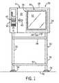
- Fig. 1is a schematic side elevation view of a commercial oven constructed in accordance with the preferred embodiment
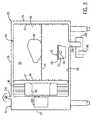
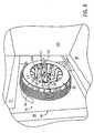
- Fig. 2is a perspective view of the interior of the oven schematically illustrated in Fig. 1 ;
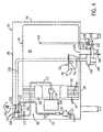
- Fig. 3is a simplified schematic illustration of various components of the oven illustrated in Fig. 2 illustrating a smoker assembly and a forced air convection assembly constructed in accordance with the preferred embodiment;
- Fig. 4is a more detailed illustration of the components of the oven illustrated in Fig. 3 further including a steam producing assembly;
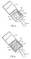
- Fig. 5is a perspective view of a smoker tray constructed in accordance with the preferred embodiment, configured in an open position;
- Fig. 6is a perspective view of the smoker tray illustrated in Fig. 5 containing smoke-producing aromatic media
- Fig. 7is a perspective view of a smoker tray illustrated in Fig. 6 in a closed position and mounted onto a tray support and igniter apparatus constructed in accordance with the preferred embodiment;
- Fig. 8is a perspective view of a boilerless convection heating assembly using resistive coil heating elements in combination with a steam producing assembly constructed in accordance with the preferred embodiment
- Fig. 9is a perspective view of the heating assembly illustrated in Fig. 8 including a plate disposed in a closed position;
- Fig. 10is a perspective view of a convection heating assembly similar to the assembly of Fig. 8 but using heat exchangers receiving heated air from gas burners in accordance with an alternate embodiment;
- Fig. 11is a perspective view of the oven illustrated in Fig. 1 having a rotisserie assembly installed in accordance with an alternate embodiment of the invention
- Fig. 12is a perspective view of a motor that drives the spit assembly illustrated in Fig. 11 ;
- Fig. 13is a perspective view of a coupling that engages the motor illustrated in Fig. 12 ;
- Fig. 14Ais a perspective view of a disc that is connected to the coupling illustrated in Fig. 13 ;
- Fig. 14Bis another perspective view of the disc illustrated in Fig. 14A ;
- Fig. 15is a side elevation view of the disc illustrated in Figs. 14A-B ;
- Fig. 16is a perspective view of a power transfer shaft that transfers power between a drive disc and a driven disc of the spit assembly;
- Fig. 17is a sectional side elevation view of the shaft illustrated in Fig. 16 ;
- Fig. 18is a perspective view of a portion of the cooking chamber illustrating a bearing that engages the driven end of the power transfer shaft illustrated in Figs. 16 and 17 ;
- Fig. 19presents various views of an angled spit that form a part of the preferred embodiment of the invention.
- Fig. 20is a perspective view of a spit assembly having a plurality of angled spits and dual pronged spits mounted in accordance with a preferred embodiment of the invention
- Fig. 21is a perspective view of the assembled spit assembly illustrated in Fig. 20 having a plurality of baskets mounted in accordance with a preferred embodiment of the invention
- Fig. 22is a perspective view of the upper wall of the cooking chamber illustrating the radiation heating elements of the rotisserie assembly
- Fig. 23Ais a perspective view of an oven including a steam-producing water tank constructed in accordance with an alternate embodiment of the invention.
- Fig. 23Bis a schematic side elevation view of the water tank illustrated in Fig. 23A .
- a commercial oven 20includes a left side wall 22 and opposing right side wall 24 that are connected to their upper and lower ends by an upper wall 26 and a base 28. Side walls 22 and 24 and upper and lower walls 26 and 28 are connected at their front and rear ends to a front end wall 30 (including a door 39) and rear end wall 32, respectively.
- Oven 20encases a generally rectangular cooking chamber 34 whose interior 36 defines a heating cavity.
- Heating cavity 36is generally defined by front and rear oven walls 30 and 32, respectively, and right side wall 24.
- the left end of heating cavity 36is bound by an internal left side wall 38 that extends parallel to outer left side wall 22.
- Left cavity side wall 38is offset from left oven side wall 22 by a sufficient distance in order to provide a housing 41 for various oven controls and electronics 45, including among other things timer and temperature controls to operate a cooking sequence in accordance with the present invention.
- the front end of heating cavity 36is defined by door 39 which is hingedly connected to right side wall 24, that and can be opened and closed via a traditional handle 40 to provide access to the heating cavity 36.
- a transparent panel 42is embedded within door 39 to enable visible access to the heating cavity 36 when the door is closed.
- a plurality of racks 44is supported by a corresponding plurality of rack supports 47 extending inwardly from left and right side walls 24 and 38.
- Racksextend horizontally between side walls 24 and 38, and support food product 46 to be prepared that is delivered into cavity 36, and facilitate removal of the food product from cavity 36 upon completion of the cooking sequence.
- a drain assembly 43extends downwardly from base 28 and enables excess moisture and grease produced as food product 48 is cooked during operation to be expelled from heating cavity 36.
- Oven 20can be supported by a support stand 50 including a plurality of vertical legs 52 that extend downwardly from base 28 and terminate at feet 54 that rest on a surface, such as a kitchen floor 56.
- Support stand 50further includes a plurality of upper rails 58 connecting the upper ends of legs 36 proximal base 28.
- a flat rectangular plate 60can be connected to the lower ends of legs 52 at a location slightly upwardly of feet 54. Plate 60 and rails 58 enhance the stability of support stand 50.
- oven 20includes a smoker assembly 62 operable to introduce flavored smoke into heating cavity 36 to be absorbed by food product 46.
- Smoker assembly 62can be used alone to cook raw food product, or can be used with a convection heat source, including forced air and/or steam, and/or a radiation heat source as will be described in more detail below.
- smoker assembly 62extends into heating cavity 36 preferably from rear wall 32.
- smoker assembly 62includes a pair generally cylindrical side-by-side heating elements 88 extending outwardly from rear wall 32.
- Heating elements 88can include a resistive coil that generates heat in response to the introduction of an electric current, and delivers the heat to an aromatic smoke producing media.
- heating elements 88can be capable of producing a momentary spark or flame sufficient to ignite a combustible aromatic media.
- Smoker assembly 62further includes a horizontally disposed cradle 87 in the form of a U-shaped bar 86 extending outwardly from rear wall 32 and into heating cavity 36.
- Cradle 87is mounted to wall 32 at a position such that heating elements 88 is disposed slightly above cradle 87, and laterally centered between the side members of bar 86.
- Smoker assembly 62includes a smoking media tray 64 having a base 66, upstanding side walls 68 and end walls 70 and 71 that collectively define an internal cavity 72 having an open upper end. Side walls 68 also extend slightly outwardly from base 66, and fit inside cradle at their lower ends.
- a cover 74is hingedly attached to the upper end of one of the end walls 70 (or alternatively side walls 68) and is sized to selectively open and close the cavity 72.
- a handle 76extends outwardly from end wall 71 such that cover 74 swings away from handle 76 when the cavity 72 is opened.
- a plurality of smoke vents 78in the form of elongated apertures extending through side walls 68 and end wall 71, enable smoke to be released from tray 64 during operation.
- a pair of round apertures 80extends through end wall 70 and is sized to receive heating elements 88.
- a aromatic smoke producing mediasuch as wood chips 84 (which can be flavored as desired), is disposed in tray 64.
- Wood chips 84are the type that char and emit flavored smoke when exposed to fire or extreme heat. Chips 84 produce a higher volume of smoke when wet or damp, as known to one of ordinary skill in the art.
- tray 64is placed in cradle 87 such that heating elements 88 extend through corresponding apertures 80.
- Wood chipsare placed in tray 64 and wetted with water, if desired, either before or after tray is placed in cradle 87.
- Cradle cover 74is then closed. Accordingly, when power is supplied to heating elements 88 (e.g., via controls 45), the temperature of the heating elements increases, thereby imparting heat to the wood chips 74 which, in turn, char and produce flavored smoke that is expelled via smoke vents 78 into cavity 36. The smoke can be produced for as long as desired until the food product has been prepared as desired.
- tray 64can be easily removed from cavity 36 once the smoking process has been completed or if, for instance, one desires to prepare a food product, such as vegetables, via a non-smoking food preparation method enabled by oven 20, such as convection and/or radiation.
- oven 20can include, along with smoker assembly 62, a convection heating assembly 90 that is configured to rapidly cook food product 46 concurrently with, or separately from, activation of smoker assembly 62.
- Heating assembly 90is mounted onto left side wall 38, and specifically in a rectangular recess formed in wall 38, and includes a radial fan 98 having blades 100 that rotate about a hub 102 under power supplied to a fan motor 103 disposed in housing 41.
- a heating element in the form of an electric resistive coil 96defines a loop that surrounds fan blades 100.
- heating assembly 90can be used to cook a food product via convection by supplying a current to resistive coil 96 while rotating fan blades 100 to disperse the heated air throughout heating cavity 36.
- a temperature sensor 97is mounted to wall 38 at a location proximal coils 96 and is sensed by controls 45 to adjust the power supply to coils 96 and regulate the temperature in heating cavity 36.
- heating assembly 90in addition to preparing food via forced air convection, cooks food product 46 by circulating steam inside cavity 36. Accordingly, a steam producing assembly 92 is provided for introducing a fluid such as water to the heating elements 46 during operation of heating assembly 90. Coils 96 vaporize the water into steam, which is circulated throughout the heating cavity 36 by rotating fan 98.
- steam producing assembly 92operates in combination with a pressure compensation tank 124 disposed proximal the intersection between left side wall 22 and upper wall 26.
- Tank 124serves multiple purposes, including venting excess pressure that accumulates in cavity 36 during food preparation, as is described in more detail below.
- Assembly 92includes a fluid intake line 122 having a first end connected to a fluid source, such as a conventional faucet or the like, a main body portion extending through left side wall 22, and a second end connected to an inlet 125 formed in a side wall of pressure compensation tank 124.
- Fluid flow through intake line 122is controlled by a solenoid valve 126 that is activated by controls 45 to inject water into pressure compensation tank 124 as needed.
- a water flow regulator 128is coupled to intake line 122 at a location downstream of valve 126, and defines an internal throughway having a diameter sized less than that of line 122 to meter the water flow rate when valve 126 is open. Water thus flows at a predetermined flow rate into inlet 125 of pressure compensation tank 124.
- a pressure compensation tank inlet 127is formed in the base of the pressure compensation tank 124, and accommodates the inlet end of a fluid delivery line 112.
- Delivery line 112further includes a main body portion extending through any suitable wall, such as side wall 38, rear wall 32, or front wall 30, and into heating cavity 36, and defines an outlet end disposed proximal fan hub 102. Conduit 112 thus enables water to travel from tank 124 to fan 98, where it is forced across heating elements 96 and vaporized into steam as will now be described.
- a water atomizer 116 of the type described in U.S. Patent No. 6,188,045is disposed at the hub 102 of fan 98 and therefore rotates during fan operation.
- Atomizer 116includes four adjoined rectangular side walls 114 that define an open outer end 117 receiving the outlet end of fluid delivery line 112.
- An elongated slot 118extends through atomizer 116 at each interface between adj acent side walls 114 such that water entering the atomizer 116 via line 112 is slung through slots 118 under centrifugal forces generated during fan rotation.
- the water exiting atomizer 116is directed over heating elements 96 that vaporize the water into steam that is circulated through cavity 36.
- heating assembly 90further includes a cover 104 that is hingedly attached to side wall 38, and that can be opened and closed to provide access to the components of heating assembly 90.
- a plurality of apertures 108extends through cover 104 that provide avenues for steam and heated air to flow into cavity 36 for the purposes of heating food product 46.
- cover 104does not span laterally the entire distance of recess 94, a pair of vertically extending gaps 106 are disposed between the cover 104 and left side wall 38 on both lateral sides of fan 98 to provide additional airflow outlets.
- a grill 105is axially aligned with fan hub 102 that presents openings extending through cover to provide an air intake for fan 98.
- Cover 104further includes a horizontal slot that accommodates fluid delivery line 112.
- heating assembly 90can use resistive coils 96 in the manner described above to heat food product 46, or alternatively can rely on a gas burner to supply the necessary heat for convection or steam cooking.
- a gas burner(not shown) can thus be provided at any desirable location having an outlet conduit in fluid communication with a plurality of heating elements 96 in the form of vertical heat exchanging tubes that largely surround fan 98 and receive hot combustion gasses from the gas burner. As fan 98 rotates, air from cavity 36 enters assembly 90 through grill 105 and is forced across heating elements 96, becomes heated, and is directed towards food product 46.
- Heating assembly 90 illustrated in Fig. 10can also provide a steamer as described above.
- fluid delivery line 112includes an intake section (not shown in Fig. 10 ) connected to an outlet section 112B that extends through cover 104.
- Outlet section 112Bextends through grill 105 to deliver water to hub 102.
- a water dispersion apparatus 116'receives the water from outlet section 112B and flings the received water towards fan blades 100, which forces the water over heating elements 96 to produce steam as described above.
- fan blades 100rotate to draw air into the fan 98 via intake grill 105.
- Wateris additionally supplied to atomizer 116 via fluid delivery line 112.
- the delivered wateris expelled radially outwardly from atomizer 116 or via slots 118 (or alternative suitable apparatus) as the fan 98 rotates, and directed via fan blades 100 towards heating elements 96 before being expelled into the heating cavity 36 via air outlets 108 as steam that heats the food product 46.
- the heating elements 96may be resistive elements or heat exchangers receiving the output of gas burners. It should be appreciated that convection heating assembly 90 is capable of cooking food product 46 via convection both alone and in combination with smoker assembly 62.
- tank 124includes a tank overflow outlet 130 that extends through a tank sidewall at a location above tank inlet 125.
- Conduit inlet 127terminates inside tank 124 at a vertical location between overflow outlet 130 and tank inlet 125.
- the water level 134 of pressure compensation tank 124is thus disposed between the inlet end of conduit 112 and overflow outlet 130 during normal operation. Accordingly, additional water added to tank 124 flows into conduit 112 and travels to the convection assembly 90 to be vaporized into steam and delivered to the food product 46 as described above.
- Condensation tank 138defines a generally rectangular housing having an open upper end that receives excess moisture, grease, and the like that is produced when preparing food product 46, via a conduit 146 coupled to drain 43 and extending below oven base 28.
- a fluid supply tube 149is connected at one end to a cool water source, and connected at its opposite end to an inlet formed in the base of tank 138 to supply cool water to the tank during operation.
- a drain assembly outlet 148extends upwardly through the bottom of condensation tank 138 a sufficient distance such that the terminal end of outlet 148 is disposed slightly above the terminal end of conduit 146.
- a water level 150is thus produced in tank 138 that ensures that the outlet of conduit 146 is submersed.
- a closed systemis therefore provided that prevents flavor-filled gasses and smoke produced during a food preparation sequence from flowing out of heating cavity 36 during normal operation.
- Condensation tank 138further includes a water temperature sensor 152 and a steam temperature sensor 154.
- Water temperature sensor 152includes a probe 156 extending into tank 138 at a level below the inlet to conduit 148 such that it is submersed in water.
- Steam temperature sensor 154includes a probe 158 extending into tank 138 at a level above the inlet to conduit 148 and a gas bypass tube 160 extending from a location inside cavity 36 that terminates at a location proximal probe 158. Steam in cavity therefore flows along bypass tube 160 and is brought into contact with probe 158 to enable a steam temperature measurement for cavity 36.
- controls 45inject additional cool water into tank 138 via a conventional valve (not shown) disposed in intake tube 149.
- a conventional valvenot shown
- steam that is brought into proximity of the water inside tank 138will condense and drain through conduit 148 as a liquid.
- controls 45actuate valve 126 to discontinue water supply to steam producing assembly 92 until the steam temperature falls below a predetermined threshold. Additionally, controls can automatically decrease the power supplied to heating elements 96 until the steam temperature falls below the predetermined threshold.
- Tank 138further enables venting of excess pressure generated inside cavity 36 during operation. Specifically, as steam, smoke, and other gasses accumulate in heating cavity 36 during a food preparation sequence, the pressure of cavity 36 correspondingly accumulates. Once the cavity pressure reaches a predetermined threshold, the pressurized steam, smoke, and other gasses flow through conduit 146 and momentarily displace the water in tank 138. Some of the gasses (i.e., steam) condenses in the tank 138 and exits tanks 138 via conduit 148 as water, while the remaining gasses follow the path of least resistance of conduit 132. The gasses then flow into pressure compensation tank 124, through an outlet channel 144, and exit the oven at a vent 136 formed in the upper surface of tank 124. It should be appreciated that the tank pressure required to begin venting is primarily determined based on the depth between the terminal ends of conduits 146 and 146, and hence the water level in condensation tank 138.
- Outlet channel 144is defined by a pair of vertical baffles 140 extending down from the upper surface of tank 124 to a distance below water level 134 to assist in pressure dissipation.
- Channel 144is further defined by a horizontal baffle 142 disposed between outlet 130 and vent 136.
- Horizontal baffle 142extends from the right side wall of tank 124 to a location short of baffles 140. Accordingly, gas outlet channel 144 extends from overflow outlet 130, around horizontal baffle 142, and towards vent 136.
- an alternative to steam assembly 92can be provided by including a steam generating water tank 135 that is either located external to the oven 20, or mounted inside cabinet 41.
- water tank 135is formed in left side wall 22 (or alternatively rear wall 32) and includes a door 147 that can be opened in the direction of Arrow A to provide access to the interior of tank 135.
- Water tank 135includes a supply input 137 that receives water from an external faucet (not shown) and a drain 139 for expelling excess water as necessary.
- a heating element, such as resistive coil 141extends into tank 135 proximal the base and is operable to heat the stored water to boiling temperature.
- a steam conduit 143extends from the upper wall of tank 135 and directs the generated steam into cavity 36 and, optionally, towards fan 98 to assist in steam circulation. It should be understood that water tank 135 can be used to replace steam assembly 92 in accordance with any of the embodiments described herein.
- steam-producing water tank 135can be provided in oven 20 in combination with pressure compensation tank 124 in the manner described above to maintain a closed food preparation system. It should also be appreciated that steam-producing water tank 135 can be provided in combination with smoker assembly 62.
- Oven 20can thus include convection heating assembly 90, in combination with steam producing assembly 92 and tank 135, and smoker assembly 62.
- oven 20can include a rotisserie assembly 160 capable of preparing food product 46 using a radiation heat source in accordance with an alternate embodiment. While only the rotisserie assembly 160 is illustrated, the present invention anticipates that assembly 160 is installed in oven 20 along with steam producing assembly 92 and tank 135, and smoker assembly 62, and, optionally, convection heating assembly 90.
- Rotisserie assembly 160includes a motor 162 (See Fig. 12 ) that drives a spit assembly 164.
- assembly 160includes a radiating heat source 166 disposed directly above spit assembly 164 and supported by upper wall 26 inside heating cavity 36.
- Heat source 166includes a plurality of rectangular ceramic disks that surrounds traditional resistive coils. The bottom of the coil (when positioned as installed in the heating cavity 36) is essentially coated with a ceramic . material which has been found to emit infrared heat that is less scattered compared to coils that are not embedded in ceramic. The food product is thus browned more uniformly than conventionally achieved.
- the coilsare connected via electrical leads to control 45, and emit heat in response to an electrical current.
- the ceramic heatersare preferably of the type commercially available from OGDEN Corp, located in Arlington Heights, IL or Chromalox, Inc. located in Pittsburgh, PA.
- the motor 162 and heating source 166are operated via controls 45.
- a temperature sensor 168(See Fig. 18 ) is mounted onto the right side wall 24 for sensing the temperature in heating cavity 36.
- the temperaturemay be displayed at the user controls 45, which includes a set of outputs as understood by a skilled artisan.
- rotisserie assembly 160further includes a spit assembly 164 having a plurality of spits (collectively identified as 170) that can span between side walls 24 and 38 of the cavity 36.
- spits 170span between a pair of support discs 172 and are suitable for supporting food product 46 such as chicken, turkey, duck, and the like.
- Discs 172are rotated under power supplied by motor 162.
- a rotating output shaft 174extends outwardly from motor 162 and through left side wall 38 of the heating cavity 36 when installed in the oven 20.
- the outer end of shaft 174includes an elongated groove 176 that bifurcates the shaft.
- Coupling 178is provided that interfaces with output shaft 174.
- Coupling 178includes a cylindrical mounting plate 180 and a shaft portion 182 extending outwardly from the mounting plate to form a motor connector 181.
- a bore 184is formed in the outer end 186 of the shaft portion 182.
- Opposing apertures 188 and 190extend through shaft portion 182 proximal the terminal end, either or both of which may receive a dowel 192.
- the inner diameter of outer end 186is slightly greater than the outer diameter of output shaft 174, such that the output shaft 174 is received by outer end 186.
- dowel 192engages groove 176 to interlock the coupling 178 with the output shaft 174, such that coupling 178 rotates along with output shaft 174 during operation.
- the mounting plate portion 180 of coupling 178includes a plurality of apertures 194 extending axially therethrough.
- disc 172includes an annular outer ring portion 198 and a pair of intersecting perpendicular ribs 200 that are connected at their outer ends to ring portion 198. Ribs 200 intersect at a hub 202 which is centrally disposed on disc 172.
- a pair of discs 172are provided in accordance with the preferred embodiment, one of which being disposed at the drive end of the spit assembly 164, the other of which being disposed at the driven end of the assembly.
- Coupling 178is mounted onto the outer surface of hub 202 via bolts (not shown) extending through apertures 194 such that dowel 192 faces outwardly and engages the motor 162 as described above.
- a shaft connector 204extends from hub 202 in a direction opposite from the direction of coupling 178 extension.
- Connector 204is generally cylindrical, and defines an outer end that defines a flat axially extending engagement surface 206 as described above with reference to motor shaft 174. Outer end of surface 206 is connected to a round member 208 that is in the shape of a half-cylinder.
- a power transfer shaft 210includes a first end 212 disposed proximal the motor, and a second distal end 214 opposite the first end 212 that is disposed remote from the motor and proximal the right side wall 24 of heating cavity 36.
- the shaft 210is symmetrical with respect to both ends 212 and 214, hence only proximal end 212 is described herein.
- a connector 216is disposed at the outer end that includes an axially extending flat surface 218 formed in a half-cylindrical surface 220.
- the flat surface 218is configured to engage flat surface 206 of connector 204, such that the connector 204 and connector 216 rotate together when connected.
- a collar 220is disposed on shaft 210 having an internal bore shaped to mate with the outer surface of the cylindrical joint formed between connectors 204 and 216. Collar 220 is thus slid over the joint to secure the connector 216 to the coupling 204.
- End 212presents a radial groove 222 that is disposed inwardly of the collar 220 (once placed in engagement with the joint) as illustrated in Figs. 20 and 21 .
- a locking ring 224is slid into engagement with the groove 222 to prevent the collar 220 from sliding out of engagement during operation.
- Distal end 214is also joined to connector 204 of a disc 172 in the manner described
- the coupling 178 that is connected to the driven end of shaft 210is further connected to a cylindrical bearing 226 extending into the heating cavity 36 from right side wall 24.
- Bearing 226includes a rotating connector member defining a groove that receives dowel 192 to lock the coupling 178 to the bearing 226 with respect to rotational motion.
- spit assemblycan be conveniently assembled and disassembled as desired.
- the couplings 178are first mounted onto hubs 202 of discs 172 in the manner described above.
- the shaft portions 182 of couplings 178are then connected to motor 162 and bearing 226, respectively.
- the shaft 210is then installed, such that ends 212 and 214 are connected to the shaft connectors 204 as described above.
- the spit assembly 164may be disassembled by reversing the assembly process, for instance when it is desired to clean the heating cavity 3 6.
- spit assembly 164is illustrated having various spits 170 extending between the discs 172 that are selectively usable depending on the food product to be prepared.
- a first angled spit 228( Fig. 19 ) includes a pair of elongated axially extending flat walls 230 that join at an axially extending apex 232 to assume the general shape of an elongated bracket. Walls 230 define a pointed end 232 that is disposed at one end of spit 228.
- a mounting pin 234extends outwardly from the pointed end 232.
- the other end of the spit 228includes a pair of mounting pins 234 extending outwardly (one from each wall 230).
- a second dual-prong spit 236( Fig. 20 ) includes a pair of cylindrical skewer rods 238 that are joined by a rib 240 at one end.
- a mounting pin 234extends outwardly from either end of each rod 238.
- the mounting pins 234are disposed remote from rib 240 may be pointed to assist in piercing uncooked food product.
- Mounting pins 234 of spit 236are spaced apart the same distance as mounting pins 234 of spit 228.
- a third spitis a basket 239 ( Fig. 21 ) that includes an axially elongated base 240 integrally connected to opposing side walls 242 that are angled outwardly with respect to the base. A pair of opposing end walls 244 closes the basket 239. Food product sits in the basket 239 during operation.
- a slot or plurality of slotsextends axially between the base 240 and side walls 242 to assist in the drainage of grease that is produced during the preparation of the food product.
- a mounting flange 246extends upwardly from each end wall 244, and supports a mounting pin 234 that extends outwardly from the flange 246. Mounting pins 234 enable rotation of the corresponding spit 170.
- Discs 172define a plurality of spit mounting locations 248 located at the outer ring portion 198 and radially offset from each other (seven illustrated). Each mounting location 248 includes two pairs of apertures designed to receive mounting pins 234.
- a first pair of apertures 250includes first and second radially aligned apertures 252 and 254, respectively.
- First aperture 252is disposed radially inwardly with respect to second aperture 254.
- a second pair of apertures 256includes tangentially aligned apertures 258 and 260.
- Apertures 258 and 260are designed to receive mounting pins 234 of the dual-pronged ends of spits 228 and 236.
- Apertures 252 and 254are designed to receive mounting pins 234 of the single-pronged ends of spits 228 and 239.
- spit 228may be orientated with the single mounting pin 234 of the pointed end 232 in the radially outer aperture 254. In this first configuration, the apex 234 points radially inwardly to position the food product away from the radiating heat elements, as will be described below.
- mounting pin 234 of the pointed end 232may be positioned in the radially inner aperture 252 such that apex 232 faces outwardly, thereby positioning the food product closer to the radiating heat elements.
- Oven 20thus advantageously incorporates a steam production assembly 92 (with or without tank 135) in combination with at least one of a convection heat source 90 and a radiation heat source 176 that browns the food being prepared.
- Heating assembly 92 together with at least one of heating assemblies 90 or 176can be used in combination with, or separately from, smoker assembly 62 to add additional smoked flavor to food product 46.
- food product 46may be heated via steam and at least one of convection and radiation while at the same time activating smoker assembly 62. Accordingly, the length of time necessary to prepare the food product 46 is significantly less than conventional smoking assemblies, and is more convenient that cooking a raw food product in a first oven, then transferring the food product to a smoker oven. Furthermore, the food product 46 is not being handled twice, thereby reducing the likelihood that the food will become contaminated. Moreover, the food product 46 will absorb a larger amount of flavorful smoke when it is raw (and being cooked) as opposed to when it has been cooked before introducing flavored smoke. The food product 46 can also be prepared via only steam and at least one of convection and radiation in situations where smoking is not desired. All of these food preparation operations can be initiated using controls 45 as appreciated by one having ordinary skill in the art.
- oven 20is more versatile than conventional ovens in that a meat product can be prepared using any of the heating methods described above that involve steam in combination with smoker 62. However, once the meat is fully prepared and removed from cavity 36, the smoke is also expelled and oven 20 can then be used to prepare food product that does not require smoking, for example vegetables, without exposing the vegetables to the smoke that was produced during the previous cooking cycle. Oven 20 can therefore prevent the transfer of smoke flavor between cooking cycles. It should furthermore be appreciated that steam assembly 92 can be activated to produce steam when it is desired to clean cavity 36.
- controls 45include timers and temperature controls to automatically initiate various cooking sequences at various temperatures for predetermined lengths of time.
- the timer and temperature controlscan be applicable to any of the heating assemblies described herein, and furthermore can operate different heating assemblies either simultaneously or concurrently.
Landscapes
- Engineering & Computer Science (AREA)
- Chemical & Material Sciences (AREA)
- Life Sciences & Earth Sciences (AREA)
- Mechanical Engineering (AREA)
- Combustion & Propulsion (AREA)
- General Engineering & Computer Science (AREA)
- Zoology (AREA)
- Food Science & Technology (AREA)
- Polymers & Plastics (AREA)
- Wood Science & Technology (AREA)
- Commercial Cooking Devices (AREA)
- General Preparation And Processing Of Foods (AREA)
- Baking, Grill, Roasting (AREA)
- Cigarettes, Filters, And Manufacturing Of Filters (AREA)
- Manufacture Of Tobacco Products (AREA)
- Food Preservation Except Freezing, Refrigeration, And Drying (AREA)
Abstract
Description
- The present invention relates generally to a cooking apparatus, and in particular to a commercial oven capable of performing multiple food preparation processes.
- Conventional steamers are suitable for preparing various food types by introducing steam into a cooking chamber to cook the food via convection. In particular, a water supply is typically introduced in the cooking chamber and delivered to one or more heating elements that evaporate the water into steam. A fan in the heating cavity circulates the steam throughout the cooking cavity. Alternatively, if a water supply is not used, the heating elements can be used to cook the food product via forced air convection. Foods suitable to be prepared by steam and convection include vegetables as well as meat, poultry, and fish products. It should be appreciated that the term "meat" is used herein to refer generally to meat, poultry, fish, and the like for the purposes of clarity and convenience.
- Conventional smokers are typically used to introduce flavored smoke into a cooking chamber, which will permeate the meat with a distinctive taste. Smokers can be used to either fully cook raw meat product, complete cooking a meat product that has been partially cooked previously in, for example a steamer or convection oven, or merely add additional flavor to a meat product that has already been fully cooked. Conventional smokers are currently available as regular smokers and pressure smokers.
- A regular smoker provides a smoke generator in the cooking chamber. The smoke generator includes wood chips or other flavor producing ingredients that may be charred upon activation of an igniter. Regular smokers operate generally at or slightly above atmospheric pressure.
- A pressure smoker is one whose cooking chamber is connected to a smoke producing unit via a supply tube. The smoker unit thus produces smoke in large quantities, and introduces the smoke into the cooking chamber via the supply tube at a rate sufficient to maintain the pressure inside the cooking chamber at a predetermined level, for example 3 PSI. It should thus be appreciated that the elevated internal pressure of a pressure smoker can cook raw meat product significantly faster than a regular smoker.
- However, regardless of the type of smoker used to prepare a raw meat product, the food preparation can consume a significant length of time that is impractical in some circumstances. If one wishes to reduce the cooking time, while producing a prepared meat product having smoked flavor, the raw meat product would first be prepared or partially prepared in a steamer or convection oven. The meat product would then be transferred into a conventional smoker to complete the food preparation sequence. This, however, is a tedious and cumbersome process. Furthermore, conventional smokers do not provide a mechanism for preparing food products that are not desired to be smoke-flavored, such as vegetables.
- It is thus desirable to provide an oven that is suitable for cooking raw food products using a heat source capable of preparing raw meat product faster than smoking alone (e.g. , convection, steam, or radiation) while simultaneously being capable of introducing flavored smoke to the food product being cooked.
- In the prior art,
US 4,474,107 discloses a food oven having the features of the precharacterising portion of the appended independent claim. - According to a first aspect of the present invention there is provided an oven capable of preparing food product utilizing a first and second food preparation process, the oven comprising:
- a heating cavity defining an interior including an apparatus for supporting food product disposed therein, and a door providing selective access to the interior; and
- a smoking assembly configured to deliver heat to an aromatic smoke producing media that emits smoke into the heating cavity in response to the delivered heat, characterized in that the oven further comprises:
- a first food preparation assembly operable to prepare raw food product using steam and at least one of radiating heat and forced air convection;
- According to a second aspect of the present invention there is a method for preparing food product utilizing a first and second food preparation process, the steps comprising:
- (A) providing a heating cavity defining an interior including an apparatus for supporting food product disposed therein and a door providing selective access to the interior; and
- (B) providing a smoking assembly configured to deliver heat to an aromatic smoke producing media that emits smoke into the heating cavity, characterized in that the method further comprises:
- (C) providing a first food preparation assembly operable to prepare raw food product using steam in combination with at least one of radiating heat and forced air convection;
- (D) operating the first food preparation assembly either simultaneously with the smoking assembly or separately from the smoking assembly; and
- (E) providing the heating cavity as a closed system to prevent flavour-filled gasses and smoke produced during a food preparation sequence from flowing out of heating cavity during normal operation.
- The foregoing and other aspects of the invention will appear from the following description. In the description, reference is made to the accompanying drawings which form a part hereof, and in which there is shown by way of illustration, and not limitation, a preferred embodiment of the invention. Such embodiment does not necessarily represent the full scope of the invention, however, and reference must therefore be made to the claims herein for interpreting the scope of the invention.
Fig. 1 is a schematic side elevation view of a commercial oven constructed in accordance with the preferred embodiment;Fig. 2 is a perspective view of the interior of the oven schematically illustrated inFig. 1 ;Fig. 3 is a simplified schematic illustration of various components of the oven illustrated inFig. 2 illustrating a smoker assembly and a forced air convection assembly constructed in accordance with the preferred embodiment;Fig. 4 is a more detailed illustration of the components of the oven illustrated inFig. 3 further including a steam producing assembly;Fig. 5 is a perspective view of a smoker tray constructed in accordance with the preferred embodiment, configured in an open position;Fig. 6 is a perspective view of the smoker tray illustrated inFig. 5 containing smoke-producing aromatic media;Fig. 7 is a perspective view of a smoker tray illustrated inFig. 6 in a closed position and mounted onto a tray support and igniter apparatus constructed in accordance with the preferred embodiment;Fig. 8 is a perspective view of a boilerless convection heating assembly using resistive coil heating elements in combination with a steam producing assembly constructed in accordance with the preferred embodiment;Fig. 9 is a perspective view of the heating assembly illustrated inFig. 8 including a plate disposed in a closed position;Fig. 10 is a perspective view of a convection heating assembly similar to the assembly ofFig. 8 but using heat exchangers receiving heated air from gas burners in accordance with an alternate embodiment;Fig. 11 is a perspective view of the oven illustrated inFig. 1 having a rotisserie assembly installed in accordance with an alternate embodiment of the invention;Fig. 12 is a perspective view of a motor that drives the spit assembly illustrated inFig. 11 ;Fig. 13 is a perspective view of a coupling that engages the motor illustrated inFig. 12 ;Fig. 14A is a perspective view of a disc that is connected to the coupling illustrated inFig. 13 ;Fig. 14B is another perspective view of the disc illustrated inFig. 14A ;Fig. 15 is a side elevation view of the disc illustrated inFigs. 14A-B ;Fig. 16 is a perspective view of a power transfer shaft that transfers power between a drive disc and a driven disc of the spit assembly;Fig. 17 is a sectional side elevation view of the shaft illustrated inFig. 16 ;Fig. 18 is a perspective view of a portion of the cooking chamber illustrating a bearing that engages the driven end of the power transfer shaft illustrated inFigs. 16 and 17 ;Fig. 19 presents various views of an angled spit that form a part of the preferred embodiment of the invention;Fig. 20 is a perspective view of a spit assembly having a plurality of angled spits and dual pronged spits mounted in accordance with a preferred embodiment of the invention;Fig. 21 is a perspective view of the assembled spit assembly illustrated inFig. 20 having a plurality of baskets mounted in accordance with a preferred embodiment of the invention;Fig. 22 is a perspective view of the upper wall of the cooking chamber illustrating the radiation heating elements of the rotisserie assembly;Fig. 23A is a perspective view of an oven including a steam-producing water tank constructed in accordance with an alternate embodiment of the invention; andFig. 23B is a schematic side elevation view of the water tank illustrated inFig. 23A .- Referring initially to
Figs. 1-4 , acommercial oven 20 includes aleft side wall 22 and opposingright side wall 24 that are connected to their upper and lower ends by anupper wall 26 and abase 28.Side walls lower walls rear end wall 32, respectively.Oven 20 encases a generallyrectangular cooking chamber 34 whose interior 36 defines a heating cavity. Heating cavity 36 is generally defined by front andrear oven walls right side wall 24. The left end ofheating cavity 36 is bound by an internalleft side wall 38 that extends parallel to outerleft side wall 22. Leftcavity side wall 38 is offset from leftoven side wall 22 by a sufficient distance in order to provide ahousing 41 for various oven controls andelectronics 45, including among other things timer and temperature controls to operate a cooking sequence in accordance with the present invention. The front end ofheating cavity 36 is defined bydoor 39 which is hingedly connected toright side wall 24, that and can be opened and closed via atraditional handle 40 to provide access to theheating cavity 36. Atransparent panel 42 is embedded withindoor 39 to enable visible access to theheating cavity 36 when the door is closed.- A plurality of
racks 44 is supported by a corresponding plurality of rack supports 47 extending inwardly from left andright side walls side walls support food product 46 to be prepared that is delivered intocavity 36, and facilitate removal of the food product fromcavity 36 upon completion of the cooking sequence. A drain assembly 43 extends downwardly frombase 28 and enables excess moisture and grease produced as food product 48 is cooked during operation to be expelled fromheating cavity 36. Oven 20 can be supported by asupport stand 50 including a plurality ofvertical legs 52 that extend downwardly frombase 28 and terminate atfeet 54 that rest on a surface, such as akitchen floor 56. Support stand 50 further includes a plurality ofupper rails 58 connecting the upper ends oflegs 36proximal base 28. A flatrectangular plate 60 can be connected to the lower ends oflegs 52 at a location slightly upwardly offeet 54.Plate 60 and rails 58 enhance the stability ofsupport stand 50.- In accordance with the preferred embodiment,
oven 20 includes asmoker assembly 62 operable to introduce flavored smoke intoheating cavity 36 to be absorbed byfood product 46.Smoker assembly 62 can be used alone to cook raw food product, or can be used with a convection heat source, including forced air and/or steam, and/or a radiation heat source as will be described in more detail below. - Referring now also to
Figs. 3-7 ,smoker assembly 62 extends intoheating cavity 36 preferably fromrear wall 32. Specifically,smoker assembly 62 includes a pair generally cylindrical side-by-side heating elements 88 extending outwardly fromrear wall 32.Heating elements 88 can include a resistive coil that generates heat in response to the introduction of an electric current, and delivers the heat to an aromatic smoke producing media. Alternatively,heating elements 88 can be capable of producing a momentary spark or flame sufficient to ignite a combustible aromatic media.Smoker assembly 62 further includes a horizontally disposedcradle 87 in the form of aU-shaped bar 86 extending outwardly fromrear wall 32 and intoheating cavity 36.Cradle 87 is mounted to wall 32 at a position such thatheating elements 88 is disposed slightly abovecradle 87, and laterally centered between the side members ofbar 86. Smoker assembly 62 includes asmoking media tray 64 having a base 66,upstanding side walls 68 and endwalls internal cavity 72 having an open upper end.Side walls 68 also extend slightly outwardly frombase 66, and fit inside cradle at their lower ends. Acover 74 is hingedly attached to the upper end of one of the end walls 70 (or alternatively side walls 68) and is sized to selectively open and close thecavity 72. Ahandle 76 extends outwardly fromend wall 71 such that cover 74 swings away fromhandle 76 when thecavity 72 is opened. A plurality of smoke vents 78, in the form of elongated apertures extending throughside walls 68 andend wall 71, enable smoke to be released fromtray 64 during operation. A pair ofround apertures 80 extends throughend wall 70 and is sized to receiveheating elements 88.- Referring now also to
Fig. 6 , a aromatic smoke producing media, such as wood chips 84 (which can be flavored as desired), is disposed intray 64. Wood chips 84 are the type that char and emit flavored smoke when exposed to fire or extreme heat.Chips 84 produce a higher volume of smoke when wet or damp, as known to one of ordinary skill in the art. - During operation,
tray 64 is placed incradle 87 such thatheating elements 88 extend throughcorresponding apertures 80. Wood chips are placed intray 64 and wetted with water, if desired, either before or after tray is placed incradle 87.Cradle cover 74 is then closed. Accordingly, when power is supplied to heating elements 88 (e.g., via controls 45), the temperature of the heating elements increases, thereby imparting heat to thewood chips 74 which, in turn, char and produce flavored smoke that is expelled via smoke vents 78 intocavity 36. The smoke can be produced for as long as desired until the food product has been prepared as desired. - Advantageously,
tray 64 can be easily removed fromcavity 36 once the smoking process has been completed or if, for instance, one desires to prepare a food product, such as vegetables, via a non-smoking food preparation method enabled byoven 20, such as convection and/or radiation. - Referring now to
Figs 3 ,4 , and8 , the present invention recognizes thatoven 20 can include, along withsmoker assembly 62, aconvection heating assembly 90 that is configured to rapidly cookfood product 46 concurrently with, or separately from, activation ofsmoker assembly 62.Heating assembly 90 is mounted ontoleft side wall 38, and specifically in a rectangular recess formed inwall 38, and includes aradial fan 98 havingblades 100 that rotate about ahub 102 under power supplied to afan motor 103 disposed inhousing 41. A heating element in the form of an electricresistive coil 96 defines a loop that surroundsfan blades 100. Accordingly, during operation,heating assembly 90 can be used to cook a food product via convection by supplying a current toresistive coil 96 while rotatingfan blades 100 to disperse the heated air throughoutheating cavity 36. Atemperature sensor 97 is mounted to wall 38 at a location proximal coils 96 and is sensed bycontrols 45 to adjust the power supply tocoils 96 and regulate the temperature inheating cavity 36. - The present invention further recognizes that
heating assembly 90, in addition to preparing food via forced air convection, cooksfood product 46 by circulating steam insidecavity 36. Accordingly, asteam producing assembly 92 is provided for introducing a fluid such as water to theheating elements 46 during operation ofheating assembly 90.Coils 96 vaporize the water into steam, which is circulated throughout theheating cavity 36 by rotatingfan 98. - Referring now to
Figs. 4 and8 in particular,steam producing assembly 92 operates in combination with apressure compensation tank 124 disposed proximal the intersection betweenleft side wall 22 andupper wall 26.Tank 124 serves multiple purposes, including venting excess pressure that accumulates incavity 36 during food preparation, as is described in more detail below.Assembly 92 includes afluid intake line 122 having a first end connected to a fluid source, such as a conventional faucet or the like, a main body portion extending throughleft side wall 22, and a second end connected to aninlet 125 formed in a side wall ofpressure compensation tank 124. - Fluid flow through
intake line 122 is controlled by asolenoid valve 126 that is activated bycontrols 45 to inject water intopressure compensation tank 124 as needed. Awater flow regulator 128 is coupled tointake line 122 at a location downstream ofvalve 126, and defines an internal throughway having a diameter sized less than that ofline 122 to meter the water flow rate whenvalve 126 is open. Water thus flows at a predetermined flow rate intoinlet 125 ofpressure compensation tank 124. - A pressure
compensation tank inlet 127 is formed in the base of thepressure compensation tank 124, and accommodates the inlet end of afluid delivery line 112.Delivery line 112 further includes a main body portion extending through any suitable wall, such asside wall 38,rear wall 32, orfront wall 30, and intoheating cavity 36, and defines an outlet end disposedproximal fan hub 102.Conduit 112 thus enables water to travel fromtank 124 tofan 98, where it is forced acrossheating elements 96 and vaporized into steam as will now be described. - In particular, a
water atomizer 116 of the type described inU.S. Patent No. 6,188,045 , the disclosure of which is hereby incorporated by reference as if set forth in its entirety herein, is disposed at thehub 102 offan 98 and therefore rotates during fan operation.Atomizer 116 includes four adjoinedrectangular side walls 114 that define an openouter end 117 receiving the outlet end offluid delivery line 112. Anelongated slot 118 extends throughatomizer 116 at each interface between adj acentside walls 114 such that water entering theatomizer 116 vialine 112 is slung throughslots 118 under centrifugal forces generated during fan rotation. Thewater exiting atomizer 116 is directed overheating elements 96 that vaporize the water into steam that is circulated throughcavity 36. - Referring also to
Fig. 9 ,heating assembly 90 further includes acover 104 that is hingedly attached toside wall 38, and that can be opened and closed to provide access to the components ofheating assembly 90. A plurality ofapertures 108 extends throughcover 104 that provide avenues for steam and heated air to flow intocavity 36 for the purposes ofheating food product 46. Furthermore, becausecover 104 does not span laterally the entire distance ofrecess 94, a pair of vertically extendinggaps 106 are disposed between thecover 104 and leftside wall 38 on both lateral sides offan 98 to provide additional airflow outlets. Agrill 105 is axially aligned withfan hub 102 that presents openings extending through cover to provide an air intake forfan 98. Cover 104 further includes a horizontal slot that accommodatesfluid delivery line 112. - Referring now to
Fig. 10 , the present invention anticipates thatheating assembly 90 can useresistive coils 96 in the manner described above to heatfood product 46, or alternatively can rely on a gas burner to supply the necessary heat for convection or steam cooking. A gas burner (not shown) can thus be provided at any desirable location having an outlet conduit in fluid communication with a plurality ofheating elements 96 in the form of vertical heat exchanging tubes that largely surroundfan 98 and receive hot combustion gasses from the gas burner. Asfan 98 rotates, air fromcavity 36 entersassembly 90 throughgrill 105 and is forced acrossheating elements 96, becomes heated, and is directed towardsfood product 46. Heating assembly 90 illustrated inFig. 10 can also provide a steamer as described above. Specifically,fluid delivery line 112 includes an intake section (not shown inFig. 10 ) connected to anoutlet section 112B that extends throughcover 104.Outlet section 112B extends throughgrill 105 to deliver water tohub 102. A water dispersion apparatus 116' receives the water fromoutlet section 112B and flings the received water towardsfan blades 100, which forces the water overheating elements 96 to produce steam as described above.- Accordingly, during operation,
fan blades 100 rotate to draw air into thefan 98 viaintake grill 105. Water is additionally supplied toatomizer 116 viafluid delivery line 112. The delivered water is expelled radially outwardly fromatomizer 116 or via slots 118 (or alternative suitable apparatus) as thefan 98 rotates, and directed viafan blades 100 towardsheating elements 96 before being expelled into theheating cavity 36 viaair outlets 108 as steam that heats thefood product 46. Theheating elements 96 may be resistive elements or heat exchangers receiving the output of gas burners. It should be appreciated thatconvection heating assembly 90 is capable of cookingfood product 46 via convection both alone and in combination withsmoker assembly 62. - It should be appreciated that either of the steam producing apparatus described above can be used with either
heating assembly 90 illustrated and described with reference toFigs. 8-10 . - Referring again to
Fig. 4 , the components and operation ofpressure compensation tank 124 will be described in more detail. Specifically,tank 124 includes atank overflow outlet 130 that extends through a tank sidewall at a location abovetank inlet 125.Conduit inlet 127 terminates insidetank 124 at a vertical location betweenoverflow outlet 130 andtank inlet 125. Thewater level 134 ofpressure compensation tank 124 is thus disposed between the inlet end ofconduit 112 andoverflow outlet 130 during normal operation. Accordingly, additional water added totank 124 flows intoconduit 112 and travels to theconvection assembly 90 to be vaporized into steam and delivered to thefood product 46 as described above. If the flow rate ofwater entering tank 124 exceeds the flow rate of water toconvection assembly 92, the water level will rise to a level above inlet toconduit 112 and even withoverflow outlet 130. The excess water will then drain intooverflow conduit 132 viaoverflow outlet 130, and flow into acondensation tank 138 located belowheating cavity 36. Condensation tank 138 defines a generally rectangular housing having an open upper end that receives excess moisture, grease, and the like that is produced when preparingfood product 46, via aconduit 146 coupled to drain 43 and extending belowoven base 28.- A
fluid supply tube 149 is connected at one end to a cool water source, and connected at its opposite end to an inlet formed in the base oftank 138 to supply cool water to the tank during operation. Adrain assembly outlet 148 extends upwardly through the bottom of condensation tank 138 a sufficient distance such that the terminal end ofoutlet 148 is disposed slightly above the terminal end ofconduit 146. Awater level 150 is thus produced intank 138 that ensures that the outlet ofconduit 146 is submersed. Advantageously, a closed system is therefore provided that prevents flavor-filled gasses and smoke produced during a food preparation sequence from flowing out ofheating cavity 36 during normal operation. Condensation tank 138 further includes awater temperature sensor 152 and asteam temperature sensor 154.Water temperature sensor 152 includes aprobe 156 extending intotank 138 at a level below the inlet toconduit 148 such that it is submersed in water.Steam temperature sensor 154 includes aprobe 158 extending intotank 138 at a level above the inlet toconduit 148 and agas bypass tube 160 extending from a location insidecavity 36 that terminates at a locationproximal probe 158. Steam in cavity therefore flows alongbypass tube 160 and is brought into contact withprobe 158 to enable a steam temperature measurement forcavity 36.- When the water temperature sensor exceeds a predetermined threshold (between 70C and 80C, and more preferably 76 C in accordance with the preferred embodiment), controls 45 inject additional cool water into
tank 138 via a conventional valve (not shown) disposed inintake tube 149. As a result, steam that is brought into proximity of the water insidetank 138 will condense and drain throughconduit 148 as a liquid. - If the steam temperature is greater than a predetermined threshold (between 80 C and 100 C, and more preferably 90C in accordance with the preferred embodiment), controls 45
actuate valve 126 to discontinue water supply to steam producingassembly 92 until the steam temperature falls below a predetermined threshold. Additionally, controls can automatically decrease the power supplied toheating elements 96 until the steam temperature falls below the predetermined threshold. Tank 138 further enables venting of excess pressure generated insidecavity 36 during operation. Specifically, as steam, smoke, and other gasses accumulate inheating cavity 36 during a food preparation sequence, the pressure ofcavity 36 correspondingly accumulates. Once the cavity pressure reaches a predetermined threshold, the pressurized steam, smoke, and other gasses flow throughconduit 146 and momentarily displace the water intank 138. Some of the gasses (i.e., steam) condenses in thetank 138 and exitstanks 138 viaconduit 148 as water, while the remaining gasses follow the path of least resistance ofconduit 132. The gasses then flow intopressure compensation tank 124, through anoutlet channel 144, and exit the oven at avent 136 formed in the upper surface oftank 124. It should be appreciated that the tank pressure required to begin venting is primarily determined based on the depth between the terminal ends ofconduits condensation tank 138.Outlet channel 144 is defined by a pair ofvertical baffles 140 extending down from the upper surface oftank 124 to a distance belowwater level 134 to assist in pressure dissipation.Channel 144 is further defined by ahorizontal baffle 142 disposed betweenoutlet 130 and vent 136.Horizontal baffle 142 extends from the right side wall oftank 124 to a location short ofbaffles 140. Accordingly,gas outlet channel 144 extends fromoverflow outlet 130, aroundhorizontal baffle 142, and towardsvent 136.- Referring now to
Figs. 23A-B , the present invention recognizes that an alternative to steamassembly 92 can be provided by including a steam generatingwater tank 135 that is either located external to theoven 20, or mounted insidecabinet 41. In particular,water tank 135 is formed in left side wall 22 (or alternatively rear wall 32) and includes adoor 147 that can be opened in the direction of Arrow A to provide access to the interior oftank 135.Water tank 135 includes asupply input 137 that receives water from an external faucet (not shown) and adrain 139 for expelling excess water as necessary. A heating element, such asresistive coil 141 extends intotank 135 proximal the base and is operable to heat the stored water to boiling temperature. Asteam conduit 143 extends from the upper wall oftank 135 and directs the generated steam intocavity 36 and, optionally, towardsfan 98 to assist in steam circulation. It should be understood thatwater tank 135 can be used to replacesteam assembly 92 in accordance with any of the embodiments described herein. - It should be further appreciated that steam-producing
water tank 135 can be provided inoven 20 in combination withpressure compensation tank 124 in the manner described above to maintain a closed food preparation system. It should also be appreciated that steam-producingwater tank 135 can be provided in combination withsmoker assembly 62. Oven 20 can thus includeconvection heating assembly 90, in combination withsteam producing assembly 92 andtank 135, andsmoker assembly 62.- Referring now to
Fig. 11 , the present invention recognizes thatoven 20 can include arotisserie assembly 160 capable of preparingfood product 46 using a radiation heat source in accordance with an alternate embodiment. While only therotisserie assembly 160 is illustrated, the present invention anticipates thatassembly 160 is installed inoven 20 along withsteam producing assembly 92 andtank 135, andsmoker assembly 62, and, optionally,convection heating assembly 90. Rotisserie assembly 160 includes a motor 162 (SeeFig. 12 ) that drives aspit assembly 164. Referring also toFig. 22 ,assembly 160 includes a radiatingheat source 166 disposed directly abovespit assembly 164 and supported byupper wall 26 insideheating cavity 36. Heatsource 166 includes a plurality of rectangular ceramic disks that surrounds traditional resistive coils. The bottom of the coil (when positioned as installed in the heating cavity 36) is essentially coated with a ceramic . material which has been found to emit infrared heat that is less scattered compared to coils that are not embedded in ceramic. The food product is thus browned more uniformly than conventionally achieved. The coils are connected via electrical leads to control 45, and emit heat in response to an electrical current. The ceramic heaters are preferably of the type commercially available from OGDEN Corp, located in Arlington Heights, IL or Chromalox, Inc. located in Pittsburgh, PA.- The motor 162 and
heating source 166 are operated viacontrols 45. A temperature sensor 168 (SeeFig. 18 ) is mounted onto theright side wall 24 for sensing the temperature inheating cavity 36. The temperature may be displayed at the user controls 45, which includes a set of outputs as understood by a skilled artisan. - Referring also to
Figs. 20 and 21 ,rotisserie assembly 160 further includes aspit assembly 164 having a plurality of spits (collectively identified as 170) that can span betweenside walls cavity 36. Specifically, spits 170 span between a pair ofsupport discs 172 and are suitable for supportingfood product 46 such as chicken, turkey, duck, and the like.Discs 172 are rotated under power supplied by motor 162. - The construction of
spit assembly 164 will now be described. Specifically, as illustrated inFig. 12 , arotating output shaft 174 extends outwardly from motor 162 and throughleft side wall 38 of theheating cavity 36 when installed in theoven 20. The outer end ofshaft 174 includes anelongated groove 176 that bifurcates the shaft. - Referring to
Fig. 13 , acoupling 178 is provided that interfaces withoutput shaft 174. Coupling 178 includes acylindrical mounting plate 180 and ashaft portion 182 extending outwardly from the mounting plate to form amotor connector 181. Abore 184 is formed in theouter end 186 of theshaft portion 182. Opposingapertures shaft portion 182 proximal the terminal end, either or both of which may receive adowel 192. The inner diameter ofouter end 186 is slightly greater than the outer diameter ofoutput shaft 174, such that theoutput shaft 174 is received byouter end 186. Specifically,dowel 192 engagesgroove 176 to interlock thecoupling 178 with theoutput shaft 174, such thatcoupling 178 rotates along withoutput shaft 174 during operation. The mountingplate portion 180 ofcoupling 178 includes a plurality ofapertures 194 extending axially therethrough. - Referring now to
Figs. 14A-B and 15 ,disc 172 includes an annularouter ring portion 198 and a pair of intersectingperpendicular ribs 200 that are connected at their outer ends to ringportion 198.Ribs 200 intersect at ahub 202 which is centrally disposed ondisc 172. A pair ofdiscs 172 are provided in accordance with the preferred embodiment, one of which being disposed at the drive end of thespit assembly 164, the other of which being disposed at the driven end of the assembly. - Coupling 178 is mounted onto the outer surface of
hub 202 via bolts (not shown) extending throughapertures 194 such thatdowel 192 faces outwardly and engages the motor 162 as described above. Ashaft connector 204 extends fromhub 202 in a direction opposite from the direction ofcoupling 178 extension.Connector 204 is generally cylindrical, and defines an outer end that defines a flat axially extendingengagement surface 206 as described above with reference tomotor shaft 174. Outer end ofsurface 206 is connected to around member 208 that is in the shape of a half-cylinder. - Referring now to
Figs. 16, 17 , and19 , apower transfer shaft 210 includes afirst end 212 disposed proximal the motor, and a seconddistal end 214 opposite thefirst end 212 that is disposed remote from the motor and proximal theright side wall 24 ofheating cavity 36. Theshaft 210 is symmetrical with respect to both ends 212 and 214, hence onlyproximal end 212 is described herein. Specifically, aconnector 216 is disposed at the outer end that includes an axially extendingflat surface 218 formed in a half-cylindrical surface 220. Theflat surface 218 is configured to engageflat surface 206 ofconnector 204, such that theconnector 204 andconnector 216 rotate together when connected. - A
collar 220 is disposed onshaft 210 having an internal bore shaped to mate with the outer surface of the cylindrical joint formed betweenconnectors Collar 220 is thus slid over the joint to secure theconnector 216 to thecoupling 204.End 212 presents aradial groove 222 that is disposed inwardly of the collar 220 (once placed in engagement with the joint) as illustrated inFigs. 20 and 21 . A lockingring 224 is slid into engagement with thegroove 222 to prevent thecollar 220 from sliding out of engagement during operation.Distal end 214 is also joined toconnector 204 of adisc 172 in the manner described - Referring to
Fig. 18 , thecoupling 178 that is connected to the driven end ofshaft 210 is further connected to acylindrical bearing 226 extending into theheating cavity 36 fromright side wall 24. Bearing 226 includes a rotating connector member defining a groove that receivesdowel 192 to lock thecoupling 178 to thebearing 226 with respect to rotational motion. - Referring to
Figs. 20-21 spit assembly can be conveniently assembled and disassembled as desired. During assembly, thecouplings 178 are first mounted ontohubs 202 ofdiscs 172 in the manner described above. Theshaft portions 182 ofcouplings 178 are then connected to motor 162 andbearing 226, respectively. Theshaft 210 is then installed, such that ends 212 and 214 are connected to theshaft connectors 204 as described above. Thespit assembly 164 may be disassembled by reversing the assembly process, for instance when it is desired to clean the heating cavity 3 6. - Referring also to
Figs. 19-21 ,spit assembly 164 is illustrated havingvarious spits 170 extending between thediscs 172 that are selectively usable depending on the food product to be prepared. In particular, a first angled spit 228 (Fig. 19 ) includes a pair of elongated axially extendingflat walls 230 that join at anaxially extending apex 232 to assume the general shape of an elongated bracket.Walls 230 define apointed end 232 that is disposed at one end of spit 228. A mountingpin 234 extends outwardly from thepointed end 232. The other end of the spit 228 includes a pair of mountingpins 234 extending outwardly (one from each wall 230). - A second dual-prong spit 236 (
Fig. 20 ) includes a pair ofcylindrical skewer rods 238 that are joined by arib 240 at one end. A mountingpin 234 extends outwardly from either end of eachrod 238. The mounting pins 234 are disposed remote fromrib 240 may be pointed to assist in piercing uncooked food product. Mountingpins 234 ofspit 236 are spaced apart the same distance as mountingpins 234 of spit 228. - A third spit is a basket 239 (
Fig. 21 ) that includes an axiallyelongated base 240 integrally connected to opposingside walls 242 that are angled outwardly with respect to the base. A pair of opposingend walls 244 closes thebasket 239. Food product sits in thebasket 239 during operation. A slot or plurality of slots (not shown) extends axially between the base 240 andside walls 242 to assist in the drainage of grease that is produced during the preparation of the food product. A mountingflange 246 extends upwardly from eachend wall 244, and supports a mountingpin 234 that extends outwardly from theflange 246. Mountingpins 234 enable rotation of thecorresponding spit 170. Discs 172 define a plurality ofspit mounting locations 248 located at theouter ring portion 198 and radially offset from each other (seven illustrated). Each mountinglocation 248 includes two pairs of apertures designed to receive mountingpins 234. In particular, a first pair ofapertures 250 includes first and second radially alignedapertures First aperture 252 is disposed radially inwardly with respect tosecond aperture 254. A second pair ofapertures 256 includes tangentially alignedapertures Apertures pins 234 of the dual-pronged ends ofspits 228 and 236.Apertures pins 234 of the single-pronged ends ofspits 228 and 239. Advantageously, for larger food product, spit 228 may be orientated with thesingle mounting pin 234 of thepointed end 232 in the radiallyouter aperture 254. In this first configuration, the apex 234 points radially inwardly to position the food product away from the radiating heat elements, as will be described below. Alternatively, for smaller food product, mountingpin 234 of thepointed end 232 may be positioned in the radiallyinner aperture 252 such thatapex 232 faces outwardly, thereby positioning the food product closer to the radiating heat elements. Sufficient clearance exists such that one end of the spits may be translated close to thecorresponding disc 172 to free the mountingpins 234 at the other end of the spit from theopposite disc 172. Accordingly, spits may be easily attached to and removed fromassembly 164.Oven 20 thus advantageously incorporates a steam production assembly 92 (with or without tank 135) in combination with at least one of aconvection heat source 90 and aradiation heat source 176 that browns the food being prepared.Heating assembly 92 together with at least one ofheating assemblies smoker assembly 62 to add additional smoked flavor tofood product 46.- Advantageously,
food product 46 may be heated via steam and at least one of convection and radiation while at the same time activatingsmoker assembly 62.
Accordingly, the length of time necessary to prepare thefood product 46 is significantly less than conventional smoking assemblies, and is more convenient that cooking a raw food product in a first oven, then transferring the food product to a smoker oven. Furthermore, thefood product 46 is not being handled twice, thereby reducing the likelihood that the food will become contaminated. Moreover, thefood product 46 will absorb a larger amount of flavorful smoke when it is raw (and being cooked) as opposed to when it has been cooked before introducing flavored smoke. Thefood product 46 can also be prepared via only steam and at least one of convection and radiation in situations where smoking is not desired. All of these food preparation operations can be initiated usingcontrols 45 as appreciated by one having ordinary skill in the art. - It should further be appreciated that
oven 20 is more versatile than conventional ovens in that a meat product can be prepared using any of the heating methods described above that involve steam in combination withsmoker 62. However, once the meat is fully prepared and removed fromcavity 36, the smoke is also expelled andoven 20 can then be used to prepare food product that does not require smoking, for example vegetables, without exposing the vegetables to the smoke that was produced during the previous cooking cycle.Oven 20 can therefore prevent the transfer of smoke flavor between cooking cycles. It should furthermore be appreciated thatsteam assembly 92 can be activated to produce steam when it is desired to cleancavity 36. - It should be appreciated that controls 45 include timers and temperature controls to automatically initiate various cooking sequences at various temperatures for predetermined lengths of time. The timer and temperature controls can be applicable to any of the heating assemblies described herein, and furthermore can operate different heating assemblies either simultaneously or concurrently.
wherein the heating cavity is a closed system to prevent flavour-filled gasses and smoke produced during a food preparation sequence from flowing out of the heating cavity during normal operation.
Claims (33)
- An oven (20) capable of preparing food product utilizing a first and second food preparation process, the oven comprising:a heating cavity (36) defining an interior including an apparatus (44) for supporting food product (46) disposed therein, and a door (39) providing selective access to the interior; anda smoking assembly (62) configured to deliver heat to an aromatic smoke producing media (84) that emits smoke into the heating cavity (36) in response to the delivered heat,characterized in that the oven further comprises:wherein the oven (20) is capable of operating the first food preparation assembly (90, 92) simultaneously with the smoking assembly (62) or separately from the smoking assembly (62); anda first food preparation assembly (90, 92) operable to prepare raw food product using steam and at least one of radiating heat and forced air convection;
wherein the heating cavity (36) is a closed system to prevent flavour-filled gasses and smoke produced during a food preparation sequence from flowing out of the heating cavity (36) during normal operation. - The oven (20) as recited in claim 1, wherein the first food preparation assembly (90, 92) comprises an air mover (98) that forces incoming air across a heating element (96) to produce heated air that is delivered to the interior of the heating cavity (36).
- The oven (20) as recited in claim 2, wherein the heating element (96) comprises a resistive member that produces heat upon receiving an electric current to produce the heated air.
- The oven (20) as recited in claim 2, wherein the heating element (96) comprises a heat exchanging tube delivering combustion gasses from a burner to produce the heated air.
- The oven (20) as recited in claim 2, wherein the food preparation assembly further comprises a steam producing assembly (92) capable of delivering a liquid across the heating element (141) that evaporates the liquid into steam that is delivered to the interior of the heating cavity (36).
- The oven (20) as recited in claim 5, wherein the steam producing assembly (92) comprises a fluid supply source (135) coupled to a conduit (143) that delivers fluid from the source (135) to the air mover (98).
- The oven (20) as recited in claim 6, wherein the steam producing assembly (92) further comprises an atomizer (116) that receives the fluid from the conduit (143) and directs the fluid over the heating element (141) under centrifugal forces provided by rotation of the air mover (98).
- The oven (20) as recited in claim 7, wherein the fluid comprises water.
- The oven (20) as recited in claim 1, wherein the first food preparation assembly (90, 92) comprises a steam producing assembly (92) including a housing containing a fluid and a heating element (141) operable to evaporate the fluid into a steam that is directed into the interior of the heating cavity (36).
- The oven (20) as recited in claim 1, further comprising a rotisserie (160) assembly including a rotatable spit assembly (164) disposed in the cavity (36) capable of bringing supported food into momentary proximity with a radiating heating element.
- The oven (20) as recited in claim 1, wherein the smoking assembly (62) comprises an ignition member (88) extending into a container (64) that houses the aromatic media (84) and contains at least one vent (78) for emitting the produced smoke.
- The oven (20) as recited in claim 11, wherein the ignition member (88) produces heat in response to an electric current sufficient to cause the media (84) to produce smoke.
- The oven (20) as recited in claim 11, wherein the ignition member (88) produces a momentary spark or flame sufficient to cause the media (84) to produce smoke.
- The oven (20) as recited in claim 11, further comprising a cradle (82) mounted to a cavity wall (32) that supports the container (64) such that the ignition member (88) extends into the container (64).
- The oven (20) as recited in claim 1, further comprising a closed venting system (146, 138, 43) that drains liquids producing during food preparation from the interior (36) while preventing gasses from escaping from the interior when the interior is pressurized below a threshold.
- The oven (20) as recited in claim 15, wherein gasses are vented from the interior (36) when the interior (36) is pressurized to a level greater than the threshold.
- The oven (20) as recited in claim 15, further comprising a condensation tank (138) that cools and liquefies some of the gasses prior to removing the liquefied gas from the cavity (36).
- A method for preparing food product utilizing a first and second food preparation process, the steps comprising:(A) providing a heating cavity (36) defining an interior including an apparatus (44) for supporting food product (46) disposed therein and a door (39) providing selective access to the interior; and(B) providing a smoking assembly (62) configured to deliver heat to an aromatic smoke producing media (84) that emits smoke into the heating cavity (36),characterized in that the method further comprises:(C) providing a first food preparation assembly (90, 92) operable to prepare raw food product using steam in combination with at least one of radiating heat and forced air convection;(D) operating the first food preparation assembly (90, 92) either simultaneously with the smoking assembly (62) or separately from the smoking assembly (62); and(E) providing the heating cavity (36) as a closed system to prevent flavour-filled gasses and smoke produced during a food preparation sequence from flowing out of heating cavity (36) during normal operation.
- The method as recited in claim 18, wherein step (D) further comprises the step of moving incoming air across a heating element (96) using an air mover (98) to produce heated air that is delivered to the interior of the heating cavity (36).
- The method as recited in claim 19, wherein step (D) further comprising the step of delivering current to a resistive member to produce the heated air.
- The method as recited in claim 19, wherein step (D) further comprises delivering combustion gasses to a heat exchanging tube to produce the heated air.
- The method as recited in claim 19, wherein step (D) further comprises delivering a liquid across the heating element (92) that evaporates the liquid into steam that is delivered to the interior of the heating cavity.
- The method as recited in claim 22, wherein step (D) further comprises delivering fluid from a fluid supply source (135) to the air mover (98).
- The method as recited in claim 23, wherein step (D) further comprises delivering the fluid to an atomizer (116) that directs the fluid over the heating element (96) under centrifugal forces provided by rotation of the air mover (98).
- The method as recited in claim 18, wherein step (D) further comprises evaporating a fluid into a gas inside a container and directing the gas into the interior of the heating cavity (36).
- The method as recited in claim 18, wherein step (D) further comprises rotating a rotisserie assembly (160) to bring supported food (46) into momentary proximity with a radiating heating element.
- The method as recited in claim 18, wherein step (B) further comprises providing an ignition member (88) extending into a container (64) that houses the aromatic media (84) and contains at least one vent (78) for emitting the produced smoke.
- The method as recited in claim 27, wherein step (D) further comprises delivering electric current to the ignition member (88) to produce heat sufficient to cause the media (84) to produce smoke.
- The method as recited in claim 27, wherein step (D) further comprises producing a momentary spark or flame sufficient to cause the media (84) to produce smoke.
- The method as recited in claim 27, wherein step (B) further comprises supporting the container (64) with a cradle (82) mounted to a cavity wall such that the ignition member (88) extends into the container (64).
- The method as recited in claim 18, further comprising draining liquids produced during food preparation from the interior (36) while preventing gasses from escaping from the interior when the interior is pressurized below a threshold.
- The method as recited in claim31, further comprising venting gasses from the interior (36) when the interior (36) is pressurized to a level greater than the threshold.
- The method as recited in claim31, further condensing some of the gasses prior to removing the liquefied gas from the cavity.
Applications Claiming Priority (2)
| Application Number | Priority Date | Filing Date | Title |
|---|---|---|---|
| US49369703P | 2003-08-08 | 2003-08-08 | |
| PCT/US2004/025808WO2005015087A2 (en) | 2003-08-08 | 2004-08-09 | Oven including smoking assembly in combination with one or more additional food preparation assemblies |
Publications (3)
| Publication Number | Publication Date |
|---|---|
| EP1659911A2 EP1659911A2 (en) | 2006-05-31 |
| EP1659911A4 EP1659911A4 (en) | 2007-08-01 |
| EP1659911B1true EP1659911B1 (en) | 2008-10-15 |
Family
ID=34135277
Family Applications (1)
| Application Number | Title | Priority Date | Filing Date |
|---|---|---|---|
| EP04780615ARevokedEP1659911B1 (en) | 2003-08-08 | 2004-08-09 | Oven including smoking assembly in combination with one or more additional food preparation assemblies |
Country Status (8)
| Country | Link |
|---|---|
| US (4) | US7157668B2 (en) |
| EP (1) | EP1659911B1 (en) |
| AT (1) | ATE410943T1 (en) |
| CA (1) | CA2534802A1 (en) |
| DE (1) | DE602004017192D1 (en) |
| ES (1) | ES2315705T3 (en) |
| MX (1) | MXPA06001562A (en) |
| WO (1) | WO2005015087A2 (en) |
Cited By (1)
| Publication number | Priority date | Publication date | Assignee | Title |
|---|---|---|---|---|
| DE102011120035A1 (en)* | 2011-12-02 | 2013-06-06 | Rational Ag | Smoking unit useful as accessory part in cooking appliance, comprises bottom tray comprising one fuel container, a plate containing smoking agent comprising one fuel container associated with smoking agent container, and a cover plate |
Families Citing this family (85)
| Publication number | Priority date | Publication date | Assignee | Title |
|---|---|---|---|---|
| US7426885B2 (en)* | 2004-12-23 | 2008-09-23 | Mclemore Don | Cooking device |
| US7703389B2 (en)* | 2003-08-14 | 2010-04-27 | Mclemore John D | Cooking apparatus with cooking characteristic monitoring system |
| US7451691B2 (en)* | 2004-03-16 | 2008-11-18 | Robertson Michael L | No waste cooking oven with multiple cooking functions |
| JP3876267B1 (en)* | 2005-08-01 | 2007-01-31 | シャープ株式会社 | Cooker |
| US7757604B2 (en)* | 2005-11-15 | 2010-07-20 | Weber-Stephen Products Co. | Smoke enhancer |
| US7698996B1 (en)* | 2006-04-28 | 2010-04-20 | Savchuk Alexander S | Smoking apparatus |
| US20080121631A1 (en)* | 2006-11-27 | 2008-05-29 | Ching-Hsiang Wang | Smoke heating oven |
| US20080121632A1 (en)* | 2006-11-27 | 2008-05-29 | Ching-Hsiang Wang | Smoking and baking oven |
| US8387613B2 (en)* | 2007-03-16 | 2013-03-05 | Cleveland Range, Inc. | Method and apparatus for a steam system |
| EP1975516B1 (en)* | 2007-03-29 | 2012-05-02 | Electrolux Home Products Corporation N.V. | Cooking oven and method for operating the same |
| WO2008138036A1 (en)* | 2007-05-09 | 2008-11-20 | Tom Cooper | Apparatus and method of smoking foodstuffs |
| US7810488B2 (en)* | 2007-05-18 | 2010-10-12 | Market Forge | High efficiency atmospheric steamer |
| ITMO20070200A1 (en)* | 2007-06-13 | 2008-12-14 | Angelo Grandi Cucine Societa P | COOKING AND SMOKING SYSTEM |
| EP2009356A1 (en)* | 2007-06-26 | 2008-12-31 | Ching-Hsiang Wang | Ofen with smoke generator |
| ITVR20070128A1 (en) | 2007-09-13 | 2009-03-14 | Inoxtrend S R L | CONVECTION OVEN |
| KR20090030974A (en)* | 2007-09-21 | 2009-03-25 | 삼성전자주식회사 | Cooking device and steam cleaning control method |
| US20090101768A1 (en)* | 2007-10-23 | 2009-04-23 | Am Wert & Associates, Llc | Magnet stand and assembly |
| WO2009070274A1 (en)* | 2007-11-28 | 2009-06-04 | Steve Hoffman | Pressurized cooking oven |
| US8272321B1 (en)* | 2007-12-20 | 2012-09-25 | Capital Cooking Equipment, Inc. | Rotisserie for oven |
| CA2709459A1 (en)* | 2008-01-09 | 2009-07-16 | Unified Brands, Inc. | Boilerless combination convection steamer oven |
| US8151697B2 (en)* | 2008-01-15 | 2012-04-10 | Premark Feg L.L.C. | Self-cleaning rotisserie oven with fan shaft seal arrangement |
| US8752538B2 (en)* | 2008-01-15 | 2014-06-17 | Premark Feg L.L.C. | Rotisserie oven with lifting wash arm |
| US20090178579A1 (en)* | 2008-01-15 | 2009-07-16 | Heiser James M | Self-cleaning rotisserie oven including oven door with labyrinth seal |
| US20090178577A1 (en)* | 2008-01-15 | 2009-07-16 | Valentine Richard D | Rotisserie oven with high temperature light gasket |
| US20090178665A1 (en)* | 2008-01-15 | 2009-07-16 | Weber Matthew A | Rotisserie with Directional Baffles |
| US8375848B2 (en)* | 2008-01-15 | 2013-02-19 | Premark Feg L.L.C. | Self-cleaning rotisserie oven |
| EP2500662B1 (en)* | 2008-01-28 | 2017-03-15 | Duke Manufacturing Company | Convection oven |
| US8304696B2 (en)* | 2008-07-01 | 2012-11-06 | Knight David B | Air circulator for an oven |
| US8193470B1 (en) | 2008-09-08 | 2012-06-05 | Kfc Corporation | Self-cleaning convection oven |
| DE102009006224A1 (en)* | 2009-01-27 | 2010-07-29 | Rational Ag | Method for selecting and arranging programs, cooking appliance therefor and kitchen network hereby |
| US8997639B2 (en)* | 2009-02-03 | 2015-04-07 | Charcoal Companion Incorporated | Smoker box for holding food flavoring wood chips or the like |
| US8304697B2 (en)* | 2009-03-27 | 2012-11-06 | Cleveland Range, Llc | Method and system for controlling smoker device integral to an oven |
| US8499683B2 (en)* | 2009-08-08 | 2013-08-06 | Steven Michael Shei | Hot and cold food holding appliance |
| ES2388855B1 (en) | 2010-02-11 | 2013-06-12 | Morganti Flavio Innovaciones Gastronómicas, S.L. | COOKING, SMOKED AND AROMATIZED DEVICE. |
| US20120088199A1 (en)* | 2010-10-06 | 2012-04-12 | General Electric Company | Apparatus and method for improved ignition of a gaseous fuel burner in an appliance |
| US20120199571A1 (en)* | 2011-02-09 | 2012-08-09 | Christopher Brown | Pressurized Cooking Oven |
| FR2976455B1 (en)* | 2011-06-14 | 2013-07-05 | Capflo Composants | COOKING OVEN WITH WATER VAPOR GENERATION |
| KR101307628B1 (en)* | 2011-07-21 | 2013-09-12 | 엘지전자 주식회사 | condensation water guiding system and steam cooker comprising the same |
| KR101168363B1 (en) | 2012-01-11 | 2012-07-24 | 주식회사 효신테크 | Combi Steam Oven with Smoker |
| ITTV20120014A1 (en) | 2012-01-27 | 2013-07-28 | Moduline Srl | COMBINED EQUIPMENT FOR COOKING FOOD AND MAINTENANCE IN TEMPERATURE WITH ACCESSORY SMOKER SYSTEM |
| EP2844921A1 (en)* | 2012-05-03 | 2015-03-11 | Arçelik Anonim Sirketi | An oven having smoking function |
| US9016285B2 (en)* | 2012-05-18 | 2015-04-28 | R.J. Reynolds Tobacco Company | Flue-curing apparatus and associated method |
| US8327756B1 (en) | 2012-07-10 | 2012-12-11 | Kitchen Concepts LLC | Oven with door locking system for cooking food under pressure |
| EP2703729B1 (en)* | 2012-08-28 | 2017-12-13 | Electrolux Home Products Corporation N.V. | A cooking oven with an oven cavity and a cleaning apparatus |
| CN206026087U (en)* | 2013-02-01 | 2017-03-22 | 沙克忍者运营有限责任公司 | Roast meat oven with steam injection |
| US20140260044A1 (en) | 2013-03-15 | 2014-09-18 | William J. Gilleran | Single wall duct flashing panel |
| US10119708B2 (en)* | 2013-04-23 | 2018-11-06 | Alto-Shaam, Inc. | Oven with automatic open/closed system mode control |
| US9538776B2 (en) | 2013-04-27 | 2017-01-10 | KitchenTek, LLC | Pressurized oven assembly |
| US9375021B2 (en) | 2013-07-29 | 2016-06-28 | Alto-Shaam, Inc. | Combination oven with reduced smoke flavor transfer |
| US10364992B2 (en) | 2013-09-05 | 2019-07-30 | Alto-Shaam, Inc. | Ventless oven hood for combination oven providing rapid access |
| EP3047474A4 (en)* | 2013-09-16 | 2017-09-13 | Lion Group Inc. | Fire fighting training system with steam/smoke generation |
| ITTV20130171A1 (en)* | 2013-10-18 | 2015-04-19 | Lainox Ali Spa | "A BAKING OVEN IN THE COLLECTIVE CATERING WITH A DEVICE FOR FLAVORING FOOD" |
| AU2014200512B2 (en)* | 2014-01-30 | 2015-10-29 | Shaker Azzam | Cooking apparatus |
| CN106455582A (en)* | 2014-03-12 | 2017-02-22 | 康威瑟姆家电公司 | Steam sensor for cooking appliances |
| WO2016093481A1 (en)* | 2014-12-10 | 2016-06-16 | 주식회사 효신테크 | Combination oven comprising built-in smoking function |
| CN106136862A (en)* | 2015-04-03 | 2016-11-23 | 漳州灿坤实业有限公司 | Steam grill toaster |
| US9677774B2 (en) | 2015-06-08 | 2017-06-13 | Alto-Shaam, Inc. | Multi-zone oven with variable cavity sizes |
| EP3104085B1 (en) | 2015-06-11 | 2025-08-20 | Electrolux Professional S.p.A. | Flavoring device for use in a cooking chamber |
| EP3104086B1 (en)* | 2015-06-11 | 2019-09-18 | Electrolux Professional S.p.A. | Flavoring device for use in a cooking chamber |
| US20170013991A1 (en)* | 2015-07-16 | 2017-01-19 | Unitherm Food Systems, Inc | Two-tier heat transfer system and method for its use |
| KR102384745B1 (en)* | 2015-09-15 | 2022-04-11 | 삼성전자주식회사 | A cooking apparatus and method for controlling the same |
| ITUB201586604U1 (en)* | 2015-10-21 | 2017-04-21 | Unox Spa | Cooking oven for food use with smoking and / or flavoring device |
| ITUB201586528U1 (en)* | 2015-10-21 | 2017-04-21 | Unox Spa | Cooking oven for food use with smoking and / or flavoring device |
| CA2948368A1 (en)* | 2015-11-15 | 2017-05-15 | Arun Hingorani | Portable wood smoker |
| US20170208825A1 (en)* | 2016-01-21 | 2017-07-27 | Alan Backus | Gaseous transfer device |
| US20170313961A1 (en)* | 2016-05-02 | 2017-11-02 | Electrolux Home Products, Inc. | Steam clean booster powder |
| DE102016215650A1 (en)* | 2016-08-19 | 2018-02-22 | BSH Hausgeräte GmbH | Haushaltsgargerät |
| WO2019032876A1 (en) | 2017-08-09 | 2019-02-14 | Sharkninja Operating Llc | Cooking device and components thereof |
| CN111315261A (en)* | 2017-11-03 | 2020-06-19 | 上海爱餐机器人(集团)有限公司 | Flushing system of cooking equipment and cooking machine for realizing totally-enclosed cooking |
| US10721939B2 (en)* | 2018-01-03 | 2020-07-28 | Kyle Riggen | Pressurized smoker for cooking |
| WO2020048687A1 (en)* | 2018-09-06 | 2020-03-12 | Arcelik Anonim Sirketi | Cooking device providing ease of use |
| US20200107565A1 (en)* | 2018-10-04 | 2020-04-09 | Electrolux Home Products, Inc. | Smoke injector for a food product |
| IT201900002207A1 (en)* | 2019-02-15 | 2020-08-15 | Landwehr Service Gmbh | PLANT AND PROCESS OF SMOKING FOOD PRODUCTS. |
| US11051654B2 (en) | 2019-02-25 | 2021-07-06 | Sharkninja Operating Llc | Cooking device and components thereof |
| WO2020176477A1 (en) | 2019-02-25 | 2020-09-03 | Sharkninja Operating Llc | Cooking system with guard |
| US12181155B2 (en)* | 2019-02-26 | 2024-12-31 | Electrolux Professional S.P.A. | Cooking oven with steam generator |
| CN212346260U (en) | 2019-02-26 | 2021-01-15 | 沙克忍者运营有限责任公司 | Cooking system capable of being positioned on a support surface and mountable cooking system |
| US12245604B2 (en) | 2019-07-29 | 2025-03-11 | Fisher & Paykel Appliances Limited | Oven smoker |
| GB2592290B (en)* | 2020-02-19 | 2024-07-24 | Gozney Group Ltd | Multi-functional open-flame oven |
| US11678765B2 (en) | 2020-03-30 | 2023-06-20 | Sharkninja Operating Llc | Cooking device and components thereof |
| CN113491454A (en) | 2020-04-06 | 2021-10-12 | 沙克忍者运营有限责任公司 | Cooking system positionable on a support surface |
| WO2022040587A1 (en)* | 2020-08-21 | 2022-02-24 | Combustion, LLC | Disposable smoke roasting device |
| US20220202027A1 (en)* | 2020-12-30 | 2022-06-30 | Sharkninja Operating Llc | Smoke functionality in electric grill-type appliance |
| US11713885B2 (en) | 2021-03-18 | 2023-08-01 | Alto-Shaam, Inc. | Oven providing surge mode cleaning |
| CN218921514U (en)* | 2022-10-13 | 2023-04-28 | 宁波吉盛电器有限公司 | An electric smoker |
Family Cites Families (65)
| Publication number | Priority date | Publication date | Assignee | Title |
|---|---|---|---|---|
| US1837924A (en)* | 1930-12-23 | 1931-12-22 | Rutherford Food Corp | Cooking apparatus |
| US2060992A (en)* | 1934-12-29 | 1936-11-17 | Ind Patents Corp | Cooker |
| US2123040A (en) | 1937-01-22 | 1938-07-05 | Benjamin B Hanak | Smoker and steam vapor cooker for hams and other meats and meat products |
| US2352590A (en)* | 1940-04-05 | 1944-06-27 | Ind Patents Corp | Smoke oven |
| US2640414A (en)* | 1950-05-17 | 1953-06-02 | Atmos Corp | Apparatus for smoking and curing food products |
| US3002444A (en)* | 1959-09-18 | 1961-10-03 | Cyril J Hoebing | Electrically heated, smoke producing barbecue grill |
| US3173358A (en)* | 1962-12-17 | 1965-03-16 | Herbert C Linquist | Barbeque apparatus |
| US3173357A (en)* | 1963-09-20 | 1965-03-16 | Jonathan E Nunnery | Broiler |
| DE1692194A1 (en) | 1967-06-03 | 1971-08-12 | Heinrich Stein | Method and device for smoking food |
| US3887716A (en)* | 1972-03-03 | 1975-06-03 | K C Seelbach Co Inc | Method and apparatus for processing foodstuffs |
| US3817166A (en)* | 1972-04-25 | 1974-06-18 | Lain L Mc | Cooking and smoking oven device |
| DE2508794A1 (en)* | 1975-02-28 | 1976-09-09 | Gaggenau Werke | OVEN WITH SMOKING EQUIPMENT |
| DE2600081A1 (en) | 1976-01-02 | 1977-07-14 | Maurer Siegfried | Drying, smoking, roasting and steaming foodstuffs, esp. meat, sausage - in closed circuit without environmental pollution |
| US4126087A (en)* | 1976-10-01 | 1978-11-21 | Mclamb Willie J | Cooker |
| US4355570A (en)* | 1978-03-31 | 1982-10-26 | Fred B. Bearden, Jr. | Barbecue oven |
| US4162650A (en)* | 1978-05-08 | 1979-07-31 | Carter Lemuel Jr | Barbeque pit apparatus |
| AT365415B (en)* | 1978-08-03 | 1982-01-11 | Maurer Siegfried | FOR TREATING FOODSTUFFS WITH SMOKING CHAMBER |
| DE2913750C2 (en) | 1979-04-03 | 1983-03-10 | Frank 2082 Tornesch Koop | Device for smoking and in particular thawing, cooking and drying food |
| DE7909941U1 (en) | 1979-04-03 | 1979-09-20 | Koop, Frank, 2082 Tornesch | DEVICE FOR HANDLING FOOD |
| DE3208874C1 (en) | 1982-03-11 | 1984-01-05 | Convotherm-Elektrogeräte GmbH, 8190 Wolfratshausen | Device for the heat treatment of food by means of a steam-air mixture |
| DE3215812A1 (en) | 1982-04-28 | 1983-11-03 | Convotherm-Elektrogeräte GmbH, 8190 Wolfratshausen | DEVICE FOR HEAT TREATING SUBSTANCES, IN PARTICULAR FOODSTUFFS |
| US4467709A (en)* | 1982-09-30 | 1984-08-28 | Anstedt Charles T | Smoker grill attachment |
| US4455924A (en)* | 1982-09-30 | 1984-06-26 | Alco Standard Corporation | Oven for cooking and flavoring meat products |
| US4474107A (en)* | 1983-03-14 | 1984-10-02 | American International Foodservice | Food oven and smoker device |
| DE3518498C1 (en)* | 1985-05-23 | 1987-02-05 | Lechmetall Landsberg Gmbh | Device for regulating the heat treatment of food |
| GB8515777D0 (en) | 1985-06-21 | 1985-07-24 | Moffat E M | Cooking apparatus |
| US4669447A (en)* | 1986-03-06 | 1987-06-02 | Kelly James S | Convection oven with hard-wood smoke generator |
| US4700685A (en) | 1986-05-09 | 1987-10-20 | Lincoln Foodservice Products, Inc. | Combination convection and steamer oven |
| DE3722282A1 (en) | 1986-11-24 | 1988-06-01 | Convotherm Elektrogeraete | DEVICE FOR HEAT TREATMENT OF FOOD |
| FR2614089B1 (en) | 1987-04-17 | 1990-01-05 | Batinox Sa | PROCESS FOR THE ELIMINATION OF VAPORS ARISING FROM COOKING IN OVENS, MEANS USING THE SAME AND OVENS PROVIDED WITH SUCH MEANS |
| US4924071A (en) | 1987-07-06 | 1990-05-08 | Woodroast Systems, Inc. | Oven |
| DE4114352C2 (en) | 1991-05-02 | 1993-12-16 | Convotherm Elektrogeraete | Grid for holding dishes |
| US5950527A (en)* | 1992-03-23 | 1999-09-14 | Charles Lyle Marren | Cooking apparatus |
| DE4234656C2 (en)* | 1992-10-14 | 1995-10-12 | Lefa Fleischerei Ausstattung | Method and device for treating incense |
| FR2711229B1 (en)* | 1993-10-12 | 1995-12-08 | Bourgeois Ste Coop Prod | Steam oven fitted with a steam evacuation device. |
| US5501142A (en)* | 1993-12-17 | 1996-03-26 | Bailey Steamer | Steamer device for cooking food in a grill |
| US5599471A (en)* | 1994-06-13 | 1997-02-04 | Zaidman; Mikhail | Compact smoking oven |
| US6152024A (en)* | 1994-09-26 | 2000-11-28 | Tippmann; Eugene R. | Apparatus and method for producing a food product |
| DE4435931C2 (en) | 1994-10-07 | 1998-06-04 | Convotherm Elektrogeraete | Operating device for a cooking appliance |
| DE4435932C2 (en) | 1994-10-07 | 1997-08-21 | Convotherm Elektrogeraete | Cooking appliance with a door closing a front opening |
| US6019033A (en)* | 1994-11-07 | 2000-02-01 | Frigoscandia, Inc. | Apparatus for steam pasteurization of food |
| US5467692A (en)* | 1995-02-17 | 1995-11-21 | Perez, Iii; Manuel | Combination outdoor cooker and smoker |
| US5869812A (en)* | 1997-09-12 | 1999-02-09 | Middleby-Marshall, Inc. | Pressure regulator for steam oven |
| US6138563A (en)* | 1997-10-22 | 2000-10-31 | Baldwin-Japan, Ltd. | Dampening water feeding method and apparatus |
| JPH11178504A (en)* | 1997-12-24 | 1999-07-06 | Higashimoto Kikai:Kk | Smoker |
| US6142066A (en)* | 1998-02-24 | 2000-11-07 | Tyson Foods, Inc. | Smoked food apparatus |
| DE29907113U1 (en) | 1999-04-22 | 1999-07-08 | Ness & Co. GmbH, 73630 Remshalden | Plant for smoking, cooking, air conditioning, maturing, cooling and baking |
| US6138553A (en)* | 1999-04-23 | 2000-10-31 | Toebben; Harvey O. | Rotary cooking apparatus |
| DE19926485C2 (en) | 1999-06-10 | 2001-09-20 | Convotherm Elektrogeraete | Method and device for regulating or controlling the humidity and / or the temperature in a cooking appliance for food |
| US6012381A (en)* | 1999-07-01 | 2000-01-11 | Hawn; Clifford W. | Convection meat cooker |
| DE19939673B4 (en) | 1999-08-20 | 2004-12-16 | AEG Hausgeräte GmbH | Oven with an outlet phase |
| DE19953226A1 (en) | 1999-11-05 | 2001-06-13 | Aeg Hausgeraete Gmbh | Domestic baking oven with smoke-curing function has control device for heating element for generation of suitable temperature time pattern for smoke-curing and for ventilation valve |
| DE19963293C1 (en) | 1999-12-27 | 2001-09-20 | Convotherm Elektrogeraete | Device for heat treatment of food |
| DE10002309C1 (en) | 2000-01-20 | 2001-10-25 | Convotherm Elektrogeraete | Electromechanical analysis method or monitoring recirculated steam and gas mixture treating foods in e.g. oven, comprises measuring slip of asynchronous fan motor under controlled conditions |
| US6188045B1 (en)* | 2000-04-03 | 2001-02-13 | Alto-Shaam, Inc. | Combination oven with three-stage water atomizer |
| JP3701839B2 (en)* | 2000-04-20 | 2005-10-05 | 株式会社フジマック | Forced convection oven drain structure |
| DE10021235A1 (en) | 2000-04-29 | 2001-10-31 | Aeg Hausgeraete Gmbh | Domestic oven has a facility for smoking food items with a ventilation and control system |
| DE10110112C1 (en) | 2001-03-02 | 2002-05-29 | Convotherm Elektrogeraete | Cooking apparatus has condensing system for steam fitted on cooking chamber consisting of flow channel and connector which in closed position connects it to atmosphere and in open position is washed with stream of water with large surface |
| US20040055477A1 (en)* | 2002-02-19 | 2004-03-25 | Swank Phillip D. | Rotisserie oven |
| US7487716B2 (en)* | 2002-02-19 | 2009-02-10 | Alto-Shaam, Inc. | Rotisserie oven |
| KR100528293B1 (en)* | 2002-11-15 | 2005-11-15 | 삼성전자주식회사 | Microwave oven and cleaning control method thereof |
| US6962106B2 (en)* | 2002-12-30 | 2005-11-08 | Viraldo John E | Outdoor cooking system |
| US6708604B1 (en)* | 2003-05-22 | 2004-03-23 | Richard A. Deichler, Jr. | Collapsible smoker and oven device |
| US6868777B1 (en)* | 2003-07-09 | 2005-03-22 | Mike Higgins | Cooker and smoker apparatus and method of smoke generation, recirculation, and exhaust |
| US7451691B2 (en)* | 2004-03-16 | 2008-11-18 | Robertson Michael L | No waste cooking oven with multiple cooking functions |
- 2004
- 2004-08-09EPEP04780615Apatent/EP1659911B1/ennot_activeRevoked
- 2004-08-09CACA002534802Apatent/CA2534802A1/ennot_activeAbandoned
- 2004-08-09USUS10/914,880patent/US7157668B2/ennot_activeExpired - Fee Related
- 2004-08-09ATAT04780615Tpatent/ATE410943T1/ennot_activeIP Right Cessation
- 2004-08-09ESES04780615Tpatent/ES2315705T3/ennot_activeExpired - Lifetime
- 2004-08-09MXMXPA06001562Apatent/MXPA06001562A/enactiveIP Right Grant
- 2004-08-09DEDE602004017192Tpatent/DE602004017192D1/ennot_activeExpired - Lifetime
- 2004-08-09WOPCT/US2004/025808patent/WO2005015087A2/enactiveApplication Filing
- 2006
- 2006-08-30USUS11/468,678patent/US7317173B2/ennot_activeExpired - Fee Related
- 2007
- 2007-11-27USUS11/945,709patent/US7755005B2/ennot_activeExpired - Fee Related
- 2010
- 2010-05-27USUS12/788,751patent/US20100229896A1/ennot_activeAbandoned
Cited By (1)
| Publication number | Priority date | Publication date | Assignee | Title |
|---|---|---|---|---|
| DE102011120035A1 (en)* | 2011-12-02 | 2013-06-06 | Rational Ag | Smoking unit useful as accessory part in cooking appliance, comprises bottom tray comprising one fuel container, a plate containing smoking agent comprising one fuel container associated with smoking agent container, and a cover plate |
Also Published As
| Publication number | Publication date |
|---|---|
| EP1659911A4 (en) | 2007-08-01 |
| ATE410943T1 (en) | 2008-10-15 |
| US7317173B2 (en) | 2008-01-08 |
| DE602004017192D1 (en) | 2008-11-27 |
| MXPA06001562A (en) | 2006-05-25 |
| US20080066629A1 (en) | 2008-03-20 |
| US7755005B2 (en) | 2010-07-13 |
| US20050051038A1 (en) | 2005-03-10 |
| EP1659911A2 (en) | 2006-05-31 |
| ES2315705T3 (en) | 2009-04-01 |
| US7157668B2 (en) | 2007-01-02 |
| US20100229896A1 (en) | 2010-09-16 |
| CA2534802A1 (en) | 2005-02-17 |
| WO2005015087A3 (en) | 2005-09-09 |
| US20060289441A1 (en) | 2006-12-28 |
| WO2005015087A2 (en) | 2005-02-17 |
Similar Documents
| Publication | Publication Date | Title |
|---|---|---|
| EP1659911B1 (en) | Oven including smoking assembly in combination with one or more additional food preparation assemblies | |
| JP5050676B2 (en) | Cooker | |
| US4810856A (en) | Rotary-spit steam cooking apparatus | |
| CA2172586C (en) | Roasting oven | |
| EP0612494A1 (en) | Rotisserie oven | |
| US20100028502A1 (en) | Charcoal smoke-far infrared ray radiating oven | |
| CN216602537U (en) | Cooking systems and combustible substrate modules for electric cooking systems | |
| US20200107565A1 (en) | Smoke injector for a food product | |
| WO2005089183A2 (en) | No waste cooking oven with multiple cooking functions | |
| WO1995020902A1 (en) | Roasting oven | |
| WO1995020902A9 (en) | Roasting oven | |
| CA3037207A1 (en) | Smoker with top heat source | |
| EP1411771B1 (en) | Roasting oven | |
| AU2018327954A1 (en) | Smoker with top heat source | |
| KR102230253B1 (en) | Flameless charcoal fire grilling device | |
| US8776675B1 (en) | Meat rotisserie and associated method | |
| WO2021170072A1 (en) | Ladder rack and heating assembly for an indoor smoker | |
| CA3102204C (en) | Removable ash clean out assembly | |
| US20130139706A1 (en) | Mobile smoker oven | |
| RU2602755C1 (en) | Method for smoking meat products with external supply of smoking flavouring agents and plant for its implementation | |
| RU2781288C1 (en) | Mobile food preparation and heating device | |
| KR20090088749A (en) | Barbecue system with steam | |
| KR970005249Y1 (en) | Meat cookware | |
| KR960007231Y1 (en) | Roaster for chicken | |
| US20090130279A1 (en) | Method and Apparatus for Smokeless Cooking |
Legal Events
| Date | Code | Title | Description |
|---|---|---|---|
| PUAI | Public reference made under article 153(3) epc to a published international application that has entered the european phase | Free format text:ORIGINAL CODE: 0009012 | |
| 17P | Request for examination filed | Effective date:20060222 | |
| AK | Designated contracting states | Kind code of ref document:A2 Designated state(s):AT BE BG CH CY CZ DE DK EE ES FI FR GB GR HU IE IT LI LU MC NL PL PT RO SE SI SK TR | |
| DAX | Request for extension of the european patent (deleted) | ||
| RIN1 | Information on inventor provided before grant (corrected) | Inventor name:BARTELICK, JANUS | |
| A4 | Supplementary search report drawn up and despatched | Effective date:20070704 | |
| RIC1 | Information provided on ipc code assigned before grant | Ipc:A23B 4/052 20060101ALI20070628BHEP Ipc:A47J 37/00 20060101AFI20050926BHEP Ipc:F24C 15/18 20060101ALI20070628BHEP | |
| RIN1 | Information on inventor provided before grant (corrected) | Inventor name:HANSEN, WILLIAM J. Inventor name:BARTELICK, JANUS Inventor name:WILLIS, PATRICK A. | |
| 17Q | First examination report despatched | Effective date:20070903 | |
| GRAP | Despatch of communication of intention to grant a patent | Free format text:ORIGINAL CODE: EPIDOSNIGR1 | |
| RIN1 | Information on inventor provided before grant (corrected) | Inventor name:WILLIS, PATRICK A. Inventor name:BARTELICK, JANUS Inventor name:HANSEN, WILLIAM J. | |
| GRAS | Grant fee paid | Free format text:ORIGINAL CODE: EPIDOSNIGR3 | |
| GRAA | (expected) grant | Free format text:ORIGINAL CODE: 0009210 | |
| AK | Designated contracting states | Kind code of ref document:B1 Designated state(s):AT BE BG CH CY CZ DE DK EE ES FI FR GB GR HU IE IT LI LU MC NL PL PT RO SE SI SK TR | |
| REG | Reference to a national code | Ref country code:CH Ref legal event code:EP Ref country code:GB Ref legal event code:FG4D | |
| REG | Reference to a national code | Ref country code:IE Ref legal event code:FG4D | |
| REF | Corresponds to: | Ref document number:602004017192 Country of ref document:DE Date of ref document:20081127 Kind code of ref document:P | |
| NLV1 | Nl: lapsed or annulled due to failure to fulfill the requirements of art. 29p and 29m of the patents act | ||
| REG | Reference to a national code | Ref country code:ES Ref legal event code:FG2A Ref document number:2315705 Country of ref document:ES Kind code of ref document:T3 | |
| PG25 | Lapsed in a contracting state [announced via postgrant information from national office to epo] | Ref country code:BG Free format text:LAPSE BECAUSE OF FAILURE TO SUBMIT A TRANSLATION OF THE DESCRIPTION OR TO PAY THE FEE WITHIN THE PRESCRIBED TIME-LIMIT Effective date:20090115 Ref country code:AT Free format text:LAPSE BECAUSE OF FAILURE TO SUBMIT A TRANSLATION OF THE DESCRIPTION OR TO PAY THE FEE WITHIN THE PRESCRIBED TIME-LIMIT Effective date:20081015 | |
| PG25 | Lapsed in a contracting state [announced via postgrant information from national office to epo] | Ref country code:PL Free format text:LAPSE BECAUSE OF FAILURE TO SUBMIT A TRANSLATION OF THE DESCRIPTION OR TO PAY THE FEE WITHIN THE PRESCRIBED TIME-LIMIT Effective date:20081015 Ref country code:NL Free format text:LAPSE BECAUSE OF FAILURE TO SUBMIT A TRANSLATION OF THE DESCRIPTION OR TO PAY THE FEE WITHIN THE PRESCRIBED TIME-LIMIT Effective date:20081015 Ref country code:PT Free format text:LAPSE BECAUSE OF FAILURE TO SUBMIT A TRANSLATION OF THE DESCRIPTION OR TO PAY THE FEE WITHIN THE PRESCRIBED TIME-LIMIT Effective date:20090316 Ref country code:SI Free format text:LAPSE BECAUSE OF FAILURE TO SUBMIT A TRANSLATION OF THE DESCRIPTION OR TO PAY THE FEE WITHIN THE PRESCRIBED TIME-LIMIT Effective date:20081015 Ref country code:FI Free format text:LAPSE BECAUSE OF FAILURE TO SUBMIT A TRANSLATION OF THE DESCRIPTION OR TO PAY THE FEE WITHIN THE PRESCRIBED TIME-LIMIT Effective date:20081015 | |
| PLBI | Opposition filed | Free format text:ORIGINAL CODE: 0009260 | |
| PLBI | Opposition filed | Free format text:ORIGINAL CODE: 0009260 | |
| PG25 | Lapsed in a contracting state [announced via postgrant information from national office to epo] | Ref country code:RO Free format text:LAPSE BECAUSE OF FAILURE TO SUBMIT A TRANSLATION OF THE DESCRIPTION OR TO PAY THE FEE WITHIN THE PRESCRIBED TIME-LIMIT Effective date:20081015 Ref country code:EE Free format text:LAPSE BECAUSE OF FAILURE TO SUBMIT A TRANSLATION OF THE DESCRIPTION OR TO PAY THE FEE WITHIN THE PRESCRIBED TIME-LIMIT Effective date:20081015 Ref country code:BE Free format text:LAPSE BECAUSE OF FAILURE TO SUBMIT A TRANSLATION OF THE DESCRIPTION OR TO PAY THE FEE WITHIN THE PRESCRIBED TIME-LIMIT Effective date:20081015 Ref country code:DK Free format text:LAPSE BECAUSE OF FAILURE TO SUBMIT A TRANSLATION OF THE DESCRIPTION OR TO PAY THE FEE WITHIN THE PRESCRIBED TIME-LIMIT Effective date:20081015 | |
| 26 | Opposition filed | Opponent name:RATIONAL AG Effective date:20090713 | |
| 26 | Opposition filed | Opponent name:RATIONAL AG Effective date:20090713 Opponent name:CONVOTHERM-ELEKTROGERAETE GMBH Effective date:20090715 | |
| PG25 | Lapsed in a contracting state [announced via postgrant information from national office to epo] | Ref country code:SE Free format text:LAPSE BECAUSE OF FAILURE TO SUBMIT A TRANSLATION OF THE DESCRIPTION OR TO PAY THE FEE WITHIN THE PRESCRIBED TIME-LIMIT Effective date:20090115 Ref country code:CZ Free format text:LAPSE BECAUSE OF FAILURE TO SUBMIT A TRANSLATION OF THE DESCRIPTION OR TO PAY THE FEE WITHIN THE PRESCRIBED TIME-LIMIT Effective date:20081015 | |
| PLAX | Notice of opposition and request to file observation + time limit sent | Free format text:ORIGINAL CODE: EPIDOSNOBS2 | |
| PG25 | Lapsed in a contracting state [announced via postgrant information from national office to epo] | Ref country code:SK Free format text:LAPSE BECAUSE OF FAILURE TO SUBMIT A TRANSLATION OF THE DESCRIPTION OR TO PAY THE FEE WITHIN THE PRESCRIBED TIME-LIMIT Effective date:20081015 | |
| PLAX | Notice of opposition and request to file observation + time limit sent | Free format text:ORIGINAL CODE: EPIDOSNOBS2 | |
| PLAB | Opposition data, opponent's data or that of the opponent's representative modified | Free format text:ORIGINAL CODE: 0009299OPPO | |
| R26 | Opposition filed (corrected) | Opponent name:CONVOTHERM-ELEKTROGERAETE GMBH Effective date:20090715 Opponent name:RATIONAL AG Effective date:20090713 | |
| PLAB | Opposition data, opponent's data or that of the opponent's representative modified | Free format text:ORIGINAL CODE: 0009299OPPO | |
| PLAF | Information modified related to communication of a notice of opposition and request to file observations + time limit | Free format text:ORIGINAL CODE: EPIDOSCOBS2 | |
| PLBB | Reply of patent proprietor to notice(s) of opposition received | Free format text:ORIGINAL CODE: EPIDOSNOBS3 | |
| PG25 | Lapsed in a contracting state [announced via postgrant information from national office to epo] | Ref country code:MC Free format text:LAPSE BECAUSE OF NON-PAYMENT OF DUE FEES Effective date:20090831 | |
| REG | Reference to a national code | Ref country code:CH Ref legal event code:PL | |
| PG25 | Lapsed in a contracting state [announced via postgrant information from national office to epo] | Ref country code:CH Free format text:LAPSE BECAUSE OF NON-PAYMENT OF DUE FEES Effective date:20090831 Ref country code:LI Free format text:LAPSE BECAUSE OF NON-PAYMENT OF DUE FEES Effective date:20090831 | |
| REG | Reference to a national code | Ref country code:IE Ref legal event code:MM4A | |
| PG25 | Lapsed in a contracting state [announced via postgrant information from national office to epo] | Ref country code:IE Free format text:LAPSE BECAUSE OF NON-PAYMENT OF DUE FEES Effective date:20090809 | |
| PG25 | Lapsed in a contracting state [announced via postgrant information from national office to epo] | Ref country code:GR Free format text:LAPSE BECAUSE OF FAILURE TO SUBMIT A TRANSLATION OF THE DESCRIPTION OR TO PAY THE FEE WITHIN THE PRESCRIBED TIME-LIMIT Effective date:20090116 | |
| PG25 | Lapsed in a contracting state [announced via postgrant information from national office to epo] | Ref country code:IT Free format text:LAPSE BECAUSE OF NON-PAYMENT OF DUE FEES Effective date:20090809 | |
| PG25 | Lapsed in a contracting state [announced via postgrant information from national office to epo] | Ref country code:LU Free format text:LAPSE BECAUSE OF NON-PAYMENT OF DUE FEES Effective date:20090809 | |
| PG25 | Lapsed in a contracting state [announced via postgrant information from national office to epo] | Ref country code:HU Free format text:LAPSE BECAUSE OF FAILURE TO SUBMIT A TRANSLATION OF THE DESCRIPTION OR TO PAY THE FEE WITHIN THE PRESCRIBED TIME-LIMIT Effective date:20090416 | |
| PGRI | Patent reinstated in contracting state [announced from national office to epo] | Ref country code:IT Effective date:20110616 | |
| PG25 | Lapsed in a contracting state [announced via postgrant information from national office to epo] | Ref country code:TR Free format text:LAPSE BECAUSE OF FAILURE TO SUBMIT A TRANSLATION OF THE DESCRIPTION OR TO PAY THE FEE WITHIN THE PRESCRIBED TIME-LIMIT Effective date:20081015 | |
| PG25 | Lapsed in a contracting state [announced via postgrant information from national office to epo] | Ref country code:CY Free format text:LAPSE BECAUSE OF FAILURE TO SUBMIT A TRANSLATION OF THE DESCRIPTION OR TO PAY THE FEE WITHIN THE PRESCRIBED TIME-LIMIT Effective date:20081015 | |
| PGFP | Annual fee paid to national office [announced via postgrant information from national office to epo] | Ref country code:FR Payment date:20110818 Year of fee payment:8 Ref country code:GB Payment date:20110803 Year of fee payment:8 Ref country code:ES Payment date:20110915 Year of fee payment:8 Ref country code:DE Payment date:20110803 Year of fee payment:8 | |
| REG | Reference to a national code | Ref country code:DE Ref legal event code:R103 Ref document number:602004017192 Country of ref document:DE Ref country code:DE Ref legal event code:R064 Ref document number:602004017192 Country of ref document:DE | |
| RDAF | Communication despatched that patent is revoked | Free format text:ORIGINAL CODE: EPIDOSNREV1 | |
| PGFP | Annual fee paid to national office [announced via postgrant information from national office to epo] | Ref country code:IT Payment date:20110811 Year of fee payment:8 | |
| RDAG | Patent revoked | Free format text:ORIGINAL CODE: 0009271 | |
| STAA | Information on the status of an ep patent application or granted ep patent | Free format text:STATUS: PATENT REVOKED | |
| 27W | Patent revoked | Effective date:20111219 | |
| GBPR | Gb: patent revoked under art. 102 of the ep convention designating the uk as contracting state | Effective date:20111219 | |
| REG | Reference to a national code | Ref country code:DE Ref legal event code:R107 Ref document number:602004017192 Country of ref document:DE Effective date:20120712 |