EP1657488B1 - Lamp for vehicles, particularly for autovehicles - Google Patents
Lamp for vehicles, particularly for autovehiclesDownload PDFInfo
- Publication number
- EP1657488B1 EP1657488B1EP05023624AEP05023624AEP1657488B1EP 1657488 B1EP1657488 B1EP 1657488B1EP 05023624 AEP05023624 AEP 05023624AEP 05023624 AEP05023624 AEP 05023624AEP 1657488 B1EP1657488 B1EP 1657488B1
- Authority
- EP
- European Patent Office
- Prior art keywords
- housing
- illuminant
- light according
- front portion
- support
- Prior art date
- Legal status (The legal status is an assumption and is not a legal conclusion. Google has not performed a legal analysis and makes no representation as to the accuracy of the status listed.)
- Active
Links
- 239000004020conductorSubstances0.000claimsdescription6
- 238000009434installationMethods0.000claimsdescription6
- 239000011888foilSubstances0.000claimsdescription4
- 238000007493shaping processMethods0.000abstractdescription3
- 238000004519manufacturing processMethods0.000description5
- 239000000463materialSubstances0.000description3
- 239000004033plasticSubstances0.000description3
- 229920003023plasticPolymers0.000description3
- 238000004026adhesive bondingMethods0.000description2
- 238000000034methodMethods0.000description2
- 230000010355oscillationEffects0.000description2
- 229920001707polybutylene terephthalatePolymers0.000description2
- 238000007789sealingMethods0.000description2
- 238000003466weldingMethods0.000description2
- 229920002319Poly(methyl acrylate)Polymers0.000description1
- 239000000853adhesiveSubstances0.000description1
- 230000001070adhesive effectEffects0.000description1
- 239000000969carrierSubstances0.000description1
- 238000013016dampingMethods0.000description1
- 230000001066destructive effectEffects0.000description1
- 239000012774insulation materialSubstances0.000description1
- 230000002045lasting effectEffects0.000description1
- 229910052754neonInorganic materials0.000description1
- GKAOGPIIYCISHV-UHFFFAOYSA-Nneon atomChemical compound[Ne]GKAOGPIIYCISHV-UHFFFAOYSA-N0.000description1
- 229920003229poly(methyl methacrylate)Polymers0.000description1
- -1polybutylene terephthalatePolymers0.000description1
- 239000004417polycarbonateSubstances0.000description1
- 229920000515polycarbonatePolymers0.000description1
- 239000004926polymethyl methacrylateSubstances0.000description1
- 238000005476solderingMethods0.000description1
- 239000007787solidSubstances0.000description1
- 239000012780transparent materialSubstances0.000description1
Images


Classifications
- B—PERFORMING OPERATIONS; TRANSPORTING
- B60—VEHICLES IN GENERAL
- B60Q—ARRANGEMENT OF SIGNALLING OR LIGHTING DEVICES, THE MOUNTING OR SUPPORTING THEREOF OR CIRCUITS THEREFOR, FOR VEHICLES IN GENERAL
- B60Q1/00—Arrangement of optical signalling or lighting devices, the mounting or supporting thereof or circuits therefor
- B60Q1/02—Arrangement of optical signalling or lighting devices, the mounting or supporting thereof or circuits therefor the devices being primarily intended to illuminate the way ahead or to illuminate other areas of way or environments
- B60Q1/04—Arrangement of optical signalling or lighting devices, the mounting or supporting thereof or circuits therefor the devices being primarily intended to illuminate the way ahead or to illuminate other areas of way or environments the devices being headlights
- B—PERFORMING OPERATIONS; TRANSPORTING
- B60—VEHICLES IN GENERAL
- B60Q—ARRANGEMENT OF SIGNALLING OR LIGHTING DEVICES, THE MOUNTING OR SUPPORTING THEREOF OR CIRCUITS THEREFOR, FOR VEHICLES IN GENERAL
- B60Q1/00—Arrangement of optical signalling or lighting devices, the mounting or supporting thereof or circuits therefor
- B60Q1/26—Arrangement of optical signalling or lighting devices, the mounting or supporting thereof or circuits therefor the devices being primarily intended to indicate the vehicle, or parts thereof, or to give signals, to other traffic
- B60Q1/2661—Arrangement of optical signalling or lighting devices, the mounting or supporting thereof or circuits therefor the devices being primarily intended to indicate the vehicle, or parts thereof, or to give signals, to other traffic mounted on parts having other functions
- B60Q1/2665—Arrangement of optical signalling or lighting devices, the mounting or supporting thereof or circuits therefor the devices being primarily intended to indicate the vehicle, or parts thereof, or to give signals, to other traffic mounted on parts having other functions on rear-view mirrors
- F—MECHANICAL ENGINEERING; LIGHTING; HEATING; WEAPONS; BLASTING
- F21—LIGHTING
- F21S—NON-PORTABLE LIGHTING DEVICES; SYSTEMS THEREOF; VEHICLE LIGHTING DEVICES SPECIALLY ADAPTED FOR VEHICLE EXTERIORS
- F21S43/00—Signalling devices specially adapted for vehicle exteriors, e.g. brake lamps, direction indicator lights or reversing lights
- F21S43/10—Signalling devices specially adapted for vehicle exteriors, e.g. brake lamps, direction indicator lights or reversing lights characterised by the light source
- F21S43/13—Signalling devices specially adapted for vehicle exteriors, e.g. brake lamps, direction indicator lights or reversing lights characterised by the light source characterised by the type of light source
- F21S43/14—Light emitting diodes [LED]
- F—MECHANICAL ENGINEERING; LIGHTING; HEATING; WEAPONS; BLASTING
- F21—LIGHTING
- F21S—NON-PORTABLE LIGHTING DEVICES; SYSTEMS THEREOF; VEHICLE LIGHTING DEVICES SPECIALLY ADAPTED FOR VEHICLE EXTERIORS
- F21S43/00—Signalling devices specially adapted for vehicle exteriors, e.g. brake lamps, direction indicator lights or reversing lights
- F21S43/10—Signalling devices specially adapted for vehicle exteriors, e.g. brake lamps, direction indicator lights or reversing lights characterised by the light source
- F21S43/19—Attachment of light sources or lamp holders
Definitions
- the inventionrelates to a light for vehicles, preferably for motor vehicles, according to the preamble of claim 1 and 2, respectively.
- the flexible illuminant carriersare advantageously made of a film-like material with conductor tracks for contacting and positioning of the LEDs. Furthermore, in addition to the LEDs, further electronic components are often arranged on the illuminant carrier.
- the light source carrier equipped with LEDsis inserted into a receiving region of the housing which is U-shaped in cross-section. If it is not held in the housing by additional positioning and fixing aids, it will cause unwanted vibrations. That is why it is also provided in this luminaire to pour the illuminant carrier into the luminaire housing or to overmold with it.
- the illuminant carrieris attached to the inside of the housing rear wall in order to achieve a positional fixation of the illuminant carrier.
- the inventionhas the object of providing the generic lamp in such a way that a particularly compact and flat, closed lighting unit in any shape can be easily and inexpensively.
- the luminous means carrieris shaped such that its shape at least partially corresponds to the inner contour of the luminaire housing.
- the illuminant carrieris at least partially fixed in the region outside the luminous means between the front housing part and the rear wall of the housing. As a result, additional positioning and fixing are not required. Also, it is not necessary to firmly connect the lamp carrier with the front housing part or the rear wall of the housing.
- the light source carrieris overlapped by the approach of the fixing element and thereby fixed in its position.
- the fixing elementis part of the housing front part, so that during assembly of the housing from the front housing part and the rear wall of the housing already the light source carrier is secured in position without additional positioning and fixing elements.
- the illuminant carriermay advantageously be a flexible conductor foil on which the illuminants are seated.
- the conductor foilcan be easily brought into the desired, adapted to the housing inner contour shape.
- the shapeis advantageously chosen so that the resulting shape ensures maximum rigidity and dimensional stability of the illuminant carrier.
- the illuminant carrierIn the interior of the lamp advantageously protrude parts of the illuminant carrier in open spaces that correspond to the dimensions and dimensions of the illuminant carrier and are formed by housing parts of the lamp.
- the illuminant carriercan be clamped positionally accurate in these spaces and thus fixed. The clamping of the illuminant carrier largely prevents the lighting means and the illuminant carrier can get into destructive vibrational states.
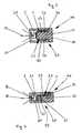
- Fig. 1shows a light source 1 with one side applied bulbs 2, preferably of LEDs. They are connected by means of metallic connection contacts 3 via, for example, soldering, welding, Toxen and similar conventional connection methods with interconnects 4 of the illuminant carrier 1.
- Thiscan be designed as a rigid board or as a film.
- the LEDs 2are assigned to a fixed position on the light source carrier 1.
- the conductor tracks 4can extend on both sides of the illuminant carrier 1 and are connected to one another, for example via connecting elements 5 in the form of plated-through holes. With this design, many electronic components can be arranged to save space on the light source carrier 1.
- LEDsinstead of the LEDs as light source 2 also incandescent or neon tubes can be used.
- a special embodimentis the use of electroluminescent films. When using such a film, which generates the light electrochemically between individual layers of this film, no metallic interconnects 4 are required for contacting other electronic components.
- the light source carrier 1can be curved in a variety of forms. This becomes necessary when the illuminant carrier 1 in luminaire / light units 20 (FIG. Fig. 3 ) is installed and this lamp unit 20 is to be adapted to contours and shape curves in interiors of vehicles or in the catchment area of a vehicle outside. Thus, it becomes possible that these lamp units 20 can be adapted to a variety of shapes and contours.
- Such applicationsmay be, for example, interior lighting of a vehicle, reading lights, ambient lights or lighting of switching and control elements.
- lamp unit 20is composed essentially of a U-shaped front housing part 21, which is preferably formed as a transparent lens, and a rear housing wall 22 together.
- the U-shaped housing front part 21advantageously has a constant wall thickness over the entire course.
- both legs 26 of the U-shaped housing front part 21are preferably designed symmetrically in their dimensions.
- the housing rear wall 22is connected inseparably in the contact region with the U-shaped housing front part 21 by a weld seam 24 or an adhesive seam 24. Thus, a closed, watertight housing 46 is created.
- the housing rear wall 22has a T-shaped cross-section, wherein the width of the T-foot corresponds to a multiple of the width of the transverse web.
- the T-footprotrudes into the front housing part 21, whose legs 26 are fastened with their free ends on the transverse web of the housing rear wall 22.
- the T-footserves as a support member 23 for fixing the position of the lamp 1.
- the length and thickness of the T-footis determined by the space required for the lamp 2 and the lamp carrier 1 installation space.
- the illuminant carrier 1is so wide that its side edges 51 can be placed around the T-foot of the housing rear wall 22.
- the side edges 51 of the illuminant carrier 1are fixed between the legs 26 of the housing front part 21 and the T-foot of the housing rear wall 22.
- the film-shaped lamp carrier 1thus also assumes U-shape.
- the luminous means 2 and the illuminant carrier 1are uniquely determined and held in position during assembly and the luminaire unit 20.
- This U-shape and the positioning of the illuminant carrier 1prevent in the assembled state of the lamp unit 20 slipping of the lamp 2 and the illuminant carrier 1. Also, this is a reliable and safe mounting of the illuminant carrier 1 in the housing 46 allows.
- the side edges 51 of the illuminant carrier 1 and the dimensions of the illuminant carrier 2correspond to the corresponding recesses of the free interior of the lamp unit 20 between the legs 26 of the housing front part 21 and the T-foot of the housing rear wall 22.
- FIG. 4Another very shallow-building embodiment is in Fig. 4 shown.
- the transparent front housing part 21is formed in a U-shaped design with different lengths of legs 29 and 30.
- the luminous means 2for example an LED, is located on the short leg 32 of the foil-like illuminant carrier 1 which is angled in an L-shaped cross-section.
- the long leg 31 of the illuminant carrier 1is in the installed state parallel to the long leg 29 of the transparent front housing part 21.
- the web 33 of the U-shaped housing front portion 21corresponds to the entire inner width of the lamp unit 20, said inner width substantially the dimensions of the light source. 2 equivalent.
- the housing rear wall 22is designed in cross-section substantially L-shaped, wherein in the assembled state of the lamp unit 20 of the long leg 29 of the housing front part 21 is connected to the front side of the short leg 32 of the housing rear wall 22.
- the short leg 30 of the front housing part 21protrudes into a recess 52 of the long leg 31.
- Both housing parts 21 and 22are corresponding Fig. 3 connected by means of suitable methods inextricably.
- the legs 29, 30 of the front housing part 21 and the rear housing wall 22are designed so that in the connecting region of the two housing parts 21, 22, a smooth, continuous outer side is formed.
- At least part of the foil-type illuminant carrier 1can be clamped between a part of the housing rear wall 22 and a part of the transparent housing front part 21 of the housing 46, which prevents oscillation / vibration of the illuminant carrier 1 and thus damage to the sensitive conductor tracks 4 of the illuminant carrier 1. Also, a detachment of the contact points between the lamp 2 and the interconnects 4 is thereby prevented.
- the inner clear width of the U-shaped transparent front housing part 21corresponds substantially to the extent of the used light source 2.
- the film-like lamp carrier 1is deformed according to the shape of the rear wall 22 or is already preformed.
- This variantis particularly space-saving and can by their compact design Therefore, for example, as a lighting unit in the vehicle interior, be installed on abutting edges or the like.
- larger lighting unitscan be assembled both laterally in the arrangement laterally and / or one above the other.
- a curved portion of a transparent housing part 21is shown.
- the basic structure of this housing part 21also corresponds to a U-shaped profile.
- the translucent outer leg 26is substantially wider than the inner leg 26.
- recesses 40corresponding to the geometric shape of the light source 2 are in the inner side at a distance behind each other. The number and position of the recesses 40 depends on the application of the lamp unit 20.
- the bulbs 2, such as LEDsare advantageously positioned for this embodiment on the foil-like lamp carrier 1 so that in the installed state of each recess 40, a light source 2 is assigned .
- the recesses 40 for receiving the LEDs 2are designed such that only small relative movements during assembly of the LEDs 2 in these recesses 40 are possible. This is of great importance, since a shift of the LEDs 2 or changes in the positional position by twisting or by distortions of the foil-like illuminant carrier 1 would impair the efficiency of the luminaire unit 20.
- oscillations of the luminous means 2 and / or of the illuminant carrier 1 during operationmay lead to a failure of the luminaire unit 20.
- 26 L-shaped fixing elements 41are provided on the outside of the inner, thin leg. They are advantageously formed integrally with the leg 26. At the free end, the fixing elements 41 are provided with a short leg 47 (FIG. FIGS. 5 and 6 ) directed towards the outer leg 26 protrudes.
- the film-like illuminant carrier 1which corresponds in its width to the distance between the projection 47 of the fixing 41 and the bottom 45 of the front housing part 21, the film-like illuminant carrier 1 is uniquely determined in its position and thus the LEDs 2 fixed in its predetermined position.
- a cover 43is applied to the front housing part 21.
- this cover 43may be made of transparent material and connected to the housing part 21 by gluing or welding. As it turned out Fig. 6 results, have the legs 26 and the legs 47 of the fixing element 41 lying in a common plane end faces, so that the lid 43 can be placed and secured reliably and clean.
- This embodiment of the FIGS. 5 and 6represents an even more compact lighting unit 20.
- the recesses 40 formed as depressionsare the same size and arranged in a row at a distance one behind the other.
- the recesses 40may also be of different sizes and / or be offset from one another, for example, in the longitudinal direction of the leg 26.
- all or only some of the recesses 40may extend over only a portion of the height of the leg 26.
- corresponding recessesmay also be provided there on the inside.
- FIGS. 5 and 6An example of the use of the lamp unit 20 according to the FIGS. 5 and 6 could be the exterior mirror housing 50 of a motor vehicle. Here, only a thin slot would be provided corresponding to the height of the lamp housing 46, which would be completely filled by the lamp unit 20 in the assembled state. A fixation or sealing of this lamp unit 20 may be by gluing or by using appropriate Seals are made in the interior of the mirror housing 50 or by other conventional fastening and sealing means. Again, there are several adjacent or juxtaposed lamp units 20, as in Fig. 7 shown, conceivable.
- FIG. 8Another application example is Fig. 8 refer to.
- a plurality of such flat lamp units 20are installed parallel to one another in a mirror housing 50. Due to the narrow slot-shaped recesses in the mirror outer housing 50, the rigidity of this mirror housing 50 is less weakened than in recesses for today commonly used lamp inserts.
- such lighting units 20can of course consist of colored materials.
- the housing components 21 and 22 of such lamp units 20can be made of hard plastics, preferably of polymethyl acrylate (PMMA) or plastics of this family.
- the rear housing part 22, such as in the 3 and 4may of course also be made of another plastic such as polycarbonate (PC), polybutylene terephthalate (PBT) or the like.
Landscapes
- Engineering & Computer Science (AREA)
- General Engineering & Computer Science (AREA)
- Mechanical Engineering (AREA)
- Physics & Mathematics (AREA)
- Microelectronics & Electronic Packaging (AREA)
- Optics & Photonics (AREA)
- Non-Portable Lighting Devices Or Systems Thereof (AREA)
- Arrangements Of Lighting Devices For Vehicle Interiors, Mounting And Supporting Thereof, Circuits Therefore (AREA)
- Arrangement Of Elements, Cooling, Sealing, Or The Like Of Lighting Devices (AREA)
- Lighting Device Outwards From Vehicle And Optical Signal (AREA)
Abstract
Description
Translated fromGermanDie Erfindung betrifft eine Leuchte für Fahrzeuge, vorzugsweise für Kraftfahrzeuge, nach dem Oberbegriff des Anspruches 1 bzw. 2.The invention relates to a light for vehicles, preferably for motor vehicles, according to the preamble of
Es sind Leuchten für Fahrzeuge bekannt, bei denen LEDs auf einem flexiblen oder festen Leuchtmittelträger sitzen. Die flexiblen Leuchtmittelträger sind vorteilhaft aus einem folienartigen Material mit Leiterbahnen zur Kontaktierung und Positionierung der LEDs versehen. Des Weiteren sind oft zusätzlich zu den LEDs weitere elektronische Bauteile auf dem Leuchtmittelträger angeordnet.There are lights for vehicles are known in which LEDs sit on a flexible or solid light source. The flexible illuminant carriers are advantageously made of a film-like material with conductor tracks for contacting and positioning of the LEDs. Furthermore, in addition to the LEDs, further electronic components are often arranged on the illuminant carrier.
Die Montage derartiger flexibler Leuchtmittelträger in Leuchten ist sehr aufwändig, da die LEDs in eine genaue Einbauposition gebracht werden müssen. Damit der Leuchtmittelträger in einfacher Weise in die gewünschte Einbaulage gebracht werden kann, sind Positionierungs- und Fixierungshilfen notwendig, die ihrerseits oft viel Einbauraum benötigen und so die Leuchte und ihre Herstellung verteuern und aufwändig gestalten. Diese aufwändigen zusätzlichen Maßnahmen schränken die beliebige Formgebung durch die Verwendung komplizierter Werkzeuge ein und stehen somit besonders kompakter Leuchtenausführungen entgegen. Weiter ist zu beachten, dass der Leuchtmittelträger mit seinen LEDs so fixiert werden muss, dass der Leuchtmittelträger nicht in Schwingungen geraten kann. Um diese Schwingungen zu vermeiden, muss oft eine zusätzliche Dämpfung durch entsprechendes Dämmmaterial in Verbindung mit dem Leuchtmittelträger verwendet werden. Erst durch alle diese Maßnahmen erhält der Leuchtmittelträger seine Formstabilität und eine über die Einsatzdauer anhaltende Betriebsfestigkeit.The installation of such flexible light source carrier in lights is very expensive, since the LEDs must be placed in an exact mounting position. So that the lamp carrier can be easily brought into the desired mounting position, positioning and fixing aids are necessary, which in turn often require a lot of installation space and so make the lamp and its manufacture more expensive and expensive. These elaborate additional measures limit the arbitrary shaping by the use of complicated tools and thus stand contrary to particularly compact luminaire designs. It should also be noted that the illuminant carrier must be fixed with its LEDs in such a way that the illuminant carrier can not vibrate. In order to avoid these vibrations, often additional damping must be used by appropriate insulation material in conjunction with the illuminant carrier. Only through all these measures does the illuminant carrier maintain its dimensional stability and an endurance lasting over the service life.
Bei der bekannten Leuchte (
Bei einer anderen bekannten Leuchte (
Der Erfindung liegt die Aufgabe zugrunde, die gattungsgemäße Leuchte so auszubilden, dass eine besonders kompakt und flach bauende, geschlossene Leuchteneinheit in beliebiger Formgebung einfach und kostengünstig hergestellt werden kann.The invention has the object of providing the generic lamp in such a way that a particularly compact and flat, closed lighting unit in any shape can be easily and inexpensively.
Diese Aufgabe wird bei der gattungsgemäßen Leuchte erfindungsgemäß mit den kennzeichnenden Merkmalen des Anspruches 1 bzw. 2 gelöst.This object is achieved in the generic lamp according to the invention with the characterizing features of
Bei der erfindungsgemäßen Leuchte ist der Leuchtmittelträger so geformt, dass seine Formgebung wenigstens teilweise der Innenkontur des Leuchtengehäuses entspricht. Bei der Leuchte nach Anspruch 1 wird der Leuchtmittelträger im Bereich außerhalb des Leuchtmittels zumindest bereichsweise zwischen dem Gehäusevorderteil und der Gehäuserückwand fixiert. Dadurch sind zusätzliche Positionierungs- und Fixiermittel nicht erforderlich. Auch ist es nicht notwendig, den Leuchtmittelträger fest mit dem Gehäusevorderteil oder der Gehäuserückwand zu verbinden.In the luminaire according to the invention, the luminous means carrier is shaped such that its shape at least partially corresponds to the inner contour of the luminaire housing. In the luminaire according to
Bei der Leuchte nach Anspruch 2 wird der Leuchtmittelträger vom Ansatz des Fixierelementes übergriffen und dadurch in seiner Lage fixiert. Das Fixierelement ist Bestandteil des Gehäusevorderteiles, so dass beim Zusammenbau des Gehäuses aus dem Gehäusevorderteil und der Gehäuserückwand bereits der Leuchtmittelträger ohne zusätzliche Positionierungs- und Fixierungselemente in seiner Lage gesichert wird.In the lamp according to
Der Leuchtmittelträger kann vorteilhaft eine flexible Leiterfolie sein, auf der die Leuchtmittel sitzen. Die Leiterfolie lässt sich einfach in die gewünschte, an die Gehäuseinnenkontur angepasste Form bringen. Die Formgebung ist vorteilhaft so gewählt, dass die entstehende Form eine Maximalsteifigkeit und Formsteifigkeit des Leuchtmittelträgers gewährleistet. Bei der Montage des Leuchtmittelträgers werden die Leuchtmittel, vorzugsweise LEDs, automatisch durch ihre vorbestimmte Position auf dem Leuchtmittelträger in der Leuchte angeordnet.The illuminant carrier may advantageously be a flexible conductor foil on which the illuminants are seated. The conductor foil can be easily brought into the desired, adapted to the housing inner contour shape. The shape is advantageously chosen so that the resulting shape ensures maximum rigidity and dimensional stability of the illuminant carrier. During assembly of the illuminant carrier, the illuminants, preferably LEDs, are automatically arranged by their predetermined position on the illuminant carrier in the luminaire.
Im Innern der Leuchte ragen vorteilhaft Teile des Leuchtmittelträgers in Freiräume, die den Abmessungen und der Dimensionierung des Leuchtmittelträgers entsprechen und von Gehäuseteilen der Leuchte gebildet werden. Der Leuchtmittelträger kann in diesen Freiräumen positionsgenau geklemmt und somit fixiert werden. Die Klemmung des Leuchtmittelträgers verhindert weitgehend, dass die Leuchtmittel und der Leuchtmittelträger in zerstörende Schwingungszustände geraten können.In the interior of the lamp advantageously protrude parts of the illuminant carrier in open spaces that correspond to the dimensions and dimensions of the illuminant carrier and are formed by housing parts of the lamp. The illuminant carrier can be clamped positionally accurate in these spaces and thus fixed. The clamping of the illuminant carrier largely prevents the lighting means and the illuminant carrier can get into destructive vibrational states.
Die genaue Positionierung und Lagefixierung werden vorteilhaft dadurch gefördert, dass im Innenraum der Leuchte Ausnehmungen zur Aufnahme der Leuchtmittel vorgesehen sind. Durch diese Maßnahmen ist es möglich, besonders raumsparende und kompakte Leuchte zu bauen, die in jeder konstruktiven Ausführung aller Bauteile einfach gestaltet sind. Sie erreichen somit ein Höchstmaß an Zuverlässigkeit und Einsatzmöglichkeit bei geringen Herstellungs- und Montagekosten.The exact positioning and position fixing are advantageously promoted by the fact that recesses are provided for receiving the lamps in the interior of the lamp. By these measures, it is possible to build a particularly space-saving and compact luminaire, which are designed simply in any constructive design of all components. They thus achieve the highest level of reliability and possible use with low manufacturing and assembly costs.
Weitere Merkmale der Erfindung ergeben sich aus den weiteren Ansprüchen, der Beschreibung und den Zeichnungen.Further features of the invention will become apparent from the other claims, the description and the drawings.
Die Erfindung wird anhand einiger in den Zeichnungen dargestellter Ausführungsformen näher erläutert. Es zeigt:
- Fig. 1
- in perspektivischer Darstellung einen Leuchtmittelträger mit einseitig aufgebrachten Leuchtmitteln,
- Fig. 2
- einen mehrfach gebogenen Leuchtmittelträger mit beidseitig aufgebrachten Leuchtmitteln,
- Fig. 3 und Fig. 4
- einen Querschnitt durch eine erfindungsgemäße Leuchte,
- Fig. 5
- eine perspektivische Ansicht einer Gehäuseausführung,
- Fig. 6
- einen Schnitt durch das Gehäuse gemäß
Fig. 5 mit eingesetztem Leuchtmittel und Leuchtmittelträger, - Fig. 7 und Fig. 8
- ein Spiegelgehäuse eines Außenrückblickspiegels mit eingesetzten Leuchten.
- Fig. 1
- a perspective view of a light source carrier with bulbs applied on one side,
- Fig. 2
- a multiply bent light source carrier with bulbs applied on both sides,
- FIG. 3 and FIG. 4
- a cross section through a lamp according to the invention,
- Fig. 5
- a perspective view of a housing design,
- Fig. 6
- a section through the housing according to
Fig. 5 with inserted illuminant and illuminant carrier, - FIGS. 7 and 8
- a mirror housing of an exterior rearview mirror with inserted lights.
Anstelle der LEDs als Leuchtmittel 2 können auch Glühlampen oder Neonröhren verwendet werden. Eine spezielle Ausführung stellt die Verwendung von elektrolumineszierenden Folien dar. Bei Einsatz einer solchen Folie, die das Licht elektrochemisch zwischen einzelnen Schichten dieser Folie erzeugt, werden keine metallischen Leiterbahnen 4 zur Kontaktierung weiterer elektronischen Bauteile mehr benötigt.Instead of the LEDs as
Entsprechend der unter
Die in
Die Gehäuserückwand 22 weist einen T-förmigen Querschnitt auf, wobei die Breite des T-Fußes einem Vielfachen der Breite des Quersteges entspricht. Im zusammengebauten Zustand ragt der T-Fuß in das Gehäusevorderteil 21, dessen Schenkel 26 mit ihren freien Enden auf dem Quersteg der Gehäuserückwand 22 befestigt sind. Der T-Fuß dient als Tragelement 23 zur Lagefixierung des Leuchtmittels 1. Die Längen- und Dickenausdehnung des T-Fußes wird durch den für das Leuchtmittel 2 und den Leuchtmittelträger 1 benötigten Einbauraum bestimmt. Wie in
Diese U-Form und die Positionierung des Leuchtmittelträgers 1 verhindern im zusammengebauten Zustand der Leuchteneinheit 20 ein Verrutschen des Leuchtmittels 2 und des Leuchtmittelträgers 1. Ebenfalls wird hierdurch eine zuverlässige und sichere Montage des Leuchtmittelträgers 1 im Gehäuse 46 ermöglicht. Hierbei entsprechen die Seitenränder 51 des Leuchtmittelträgers 1 und die Abmessungen des Leuchtmittelträgers 2 den zugehörigen Ausnehmungen des freien Innenraumes der Leuchteneinheit 20 zwischen den Schenkeln 26 des Gehäusevorderteiles 21 und dem T-Fuß der Gehäuserückwand 22. Diese konstruktiven Maßnahmen und Auslegungen ermöglichen eine kostengünstige Herstellung und Montage derartiger Leuchteneinheiten 20.This U-shape and the positioning of the
Eine weitere, sehr flach bauende Ausführungsform ist in
Der lange Schenkel 31 des Leuchtmittelträgers 1 liegt in eingebautem Zustand parallel zum langen Schenkel 29 des transparenten Gehäusevorderteiles 21. Der Steg 33 des im Querschnitt U-förmigen Gehäusevorderteiles 21 entspricht der gesamten Innenbreite der Leuchteneinheit 20, wobei diese Innenbreite im wesentlichen den Abmessungen des Leuchtmittels 2 entspricht.The
Die Gehäuserückwand 22 ist im Querschnitt im wesentlichen L-förmig gestaltet, wobei im zusammengebauten Zustand der Leuchteneinheit 20 der lange Schenkel 29 des Gehäusevorderteiles 21 mit der Stirnseite des kurzen Schenkels 32 der Gehäuserückwand 22 verbunden ist. Der kurze Schenkel 30 des Gehäusevorderteiles 21 ragt in eine Ausnehmung 52 des langen Schenkels 31. Beide Gehäuseteile 21 und 22 sind entsprechend
Bei den Ausführungsformen nach den
Die innere lichte Weite des U-förmigen transparenten Gehäusevorderteiles 21 entspricht im wesentlichen der Ausdehnung des verwendeten Leuchtmittels 2. Bei der Montage dieser Ausführung wird vorausgesetzt, daß der folienartige Leuchtmittelträger 1 entsprechend der Formgebung der Gehäuserückwand 22 verformt wird oder bereits vorgeformt ist. Diese Ausführungsvariante ist durch ihre kompakte Bauweise besonders raumsparend und kann daher gut zum Beispiel als Beleuchtungseinheit im Fahrzeuginnenraum, an Stoßkanten oder dergleichen eingebaut werden.The inner clear width of the U-shaped transparent
Durch Kombination gleicher derartiger Leuchteneinheiten 20 können sowohl in der Anordnung seitlich nebeneinander und/oder auch übereinander größere Leuchteneinheiten zusammengestellt werden.By combining the same type of
Für den Einsatz gebogener Ausführungen dieser Leuchteneinheit 20 bietet sich die Lösung gemäß
Um auch hier die Montage möglichst einfach und sicher gestalten zu können, sind an der Außenseite des inneren, dünnen Schenkels 26 L-förmige Fixierelemente 41 vorgesehen. Sie sind vorteilhaft einstückig mit dem Schenkel 26 ausgebildet. Am freien Ende sind die Fixierelemente 41 mit einem kurzen Schenkel 47 (
Im dargestellten Ausführungsbeispiel sind die als Vertiefungen ausgebildeten Ausnehmungen 40 gleich groß und in einer Reihe mit Abstand hintereinander angeordnet. Die Ausnehmungen 40 können auch unterschiedlich groß sein und/oder beispielsweise in Längsrichtung des Schenkels 26 versetzt zueinander angeordnet sein.In the illustrated embodiment, the
Vorteilhaft erstrecken sich die Ausnehmungen 40 vom Boden 45 aus über die Höhe des Schenkels 26. Je nach Ausbildung der Leuchtmittel 2 oder Einsatzfall der Leuchteneinheit 20 können sich alle oder nur einige der Ausnehmungen 40 nur über einen Teil der Höhe des Schenkels 26 erstrecken.Depending on the design of the
Bei entsprechender Dicke des anderen Schenkels 26 können auch dort an der Innenseite entsprechende Ausnehmungen vorgesehen sein.With a corresponding thickness of the
Ein Beispiel für den Einsatz der Leuchteneinheit 20 gemäß den
Ein weiteres Anwendungsbeispiel ist
Durch die einfache Herstellung dieser Leuchteneinheiten 20 sind besonders kostengünstige Ausführungen von Beleuchtungseinrichtungen möglich. Die geringen Abmessungen derartiger Leuchteneinheiten 20 ermöglichen die Kombination von mehreren Leuchteneinheiten 20 bei geringerem Einbauraum und minimalen Material- und Herstellungskosten.Due to the simple production of these
Durch die Verwendung weniger Bauteile und durch die einfache konstruktive Ausführung der Gehäuseteile ist eine automatisierte Montage der Leuchteneinheiten 20 denkbar.By using fewer components and by the simple structural design of the housing parts an automated assembly of the
Entsprechend heute gebräuchlicher Ausführungen können derartige Leuchteneinheiten 20 selbstverständlich aus eingefärbten Materialien bestehen.According to today common designs,
Ebenso sind sowohl an der Innenseite wie auch im äußeren Bereich der Leuchteneinheit 20 aufgebrachte Optiken denkbar. Die Gehäusebauteile 21 und 22 derartiger Leuchteneinheiten 20 können aus harten Kunststoffen, vorzugsweise aus Polymethylacrylat (PMMA) oder Kunststoffen dieser Familie hergestellt werden. Das rückwärtige Gehäuseteil 22, wie beispielsweise in den
Claims (19)
- A light for vehicles, preferably for motor vehicles, comprising a housing (46), which is comprised of at least one housing front portion (21) and a housing rear wall (22), and which is provided with at least one illuminant (2), whose rays pass to the outside and which is mounted on an illuminant support (1), whose shape at least partially corresponds to the inner contour of the housing (46), wherein the illuminant support (1) is fixated in the portion outside of the illuminant (2) at least in sections between the housing front portion (21) and the housing rear wall (22).
- A light for vehicles, preferably for motor vehicles, comprising a housing (46), which is comprised of at least one housing front portion (21) and a housing rear wall (22), and which is provided with at least one illuminant (2), whose rays pass to the outside, and which is mounted on an illuminant support (1), whose shape at least partially corresponds to the inner contour of the housing (46), wherein the housing front portion (21) is at least provided with one fixation element (41) for the illuminant support (1), wherein said fixation element comprises a shoulder (47), reaching over the illuminant support (1) for positional fixation.
- A light according to claim 1 or 2, wherein the inner contour of the housing (46) is U-shaped in cross section.
- A light according to claim 1 or 2, wherein the inner contour of the housing (46) is L-shaped in cross section.
- A light according to claim 1 or 2, wherein the inner contour of the housing (46) is provided curved at least in portions.
- A light according to one of the claims 1 through 5, wherein the illuminant support (1) is in contact with the inside of the housing rear wall (22) at least in portions.
- A light according to one of the claims 1 through 6, wherein the illuminant support (1) is clamped at least in portions between the housing front portion (21) and the housing rear wall (22), so it cannot move.
- A light according to one of the claims 1 through 7, wherein at least a portion of the housing front portion (21) forms the light pane of the light.
- A light according to one of the claims 1 through 8, wherein the housing front portion (21) is U-shaped in cross section, wherein the U has identical or different arms.
- A light according to one of the claims 1 through 9, wherein the housing (46) of the light unit (20) is closed.
- A light according to one of the claims 1 through 10, wherein the illuminant (2) is an LED.
- A light according to one of the claims 1 through 10, wherein the illuminant (2) is an incandescent lamp.
- A light according to one of the claims 1 through 10, wherein the illuminant (2) is an electroluminescent foil and comprises the same profile as the illuminant support (1).
- A light according to one of the claims 1 through 13, wherein the housing (46) comprises recesses (40) for the illuminant (2), which are preferably formed by depressions on the inside of the housing front portion (21).
- A light according to claim 14, wherein the recesses (40) are provided on the inside of at least arm (26) of the housing front component (21) and are preferably disposed distributed over the length of the housing (46).
- A light according to claim 14 or 15, wherein the illuminants (2) are positioned in the recesses (40), so they cannot move.
- A light according to one of the claims 2 through 16, wherein the fixation element (41) is configured integrally with the housing front portion (21).
- A light according to one of the claims 2 through 17, wherein the shoulder (47) extends into an installation cavity for the illuminant support (1).
- A light according to one of the claims 1 through 18, wherein the illuminant support (1) is a flexible conductor foil, at which the illuminants (2) are advantageously disposed on one side, preferably disposed on both sides.
Priority Applications (1)
| Application Number | Priority Date | Filing Date | Title |
|---|---|---|---|
| SI200530447TSI1657488T1 (en) | 2004-11-13 | 2005-10-28 | Lamp for vehicles, particularly for autovehicles |
Applications Claiming Priority (1)
| Application Number | Priority Date | Filing Date | Title |
|---|---|---|---|
| DE102004054822ADE102004054822A1 (en) | 2004-11-13 | 2004-11-13 | Luminaire for vehicles, preferably for motor vehicles |
Publications (3)
| Publication Number | Publication Date |
|---|---|
| EP1657488A2 EP1657488A2 (en) | 2006-05-17 |
| EP1657488A3 EP1657488A3 (en) | 2007-02-28 |
| EP1657488B1true EP1657488B1 (en) | 2008-10-15 |
Family
ID=35520010
Family Applications (1)
| Application Number | Title | Priority Date | Filing Date |
|---|---|---|---|
| EP05023624AActiveEP1657488B1 (en) | 2004-11-13 | 2005-10-28 | Lamp for vehicles, particularly for autovehicles |
Country Status (6)
| Country | Link |
|---|---|
| US (1) | US7500771B2 (en) |
| EP (1) | EP1657488B1 (en) |
| KR (1) | KR101056236B1 (en) |
| AT (1) | ATE411492T1 (en) |
| DE (2) | DE102004054822A1 (en) |
| SI (1) | SI1657488T1 (en) |
Cited By (1)
| Publication number | Priority date | Publication date | Assignee | Title |
|---|---|---|---|---|
| EP3061587A1 (en) | 2015-02-24 | 2016-08-31 | SMR Patents S.à.r.l. | Method for producing a light for vehicles and external mirror assembly of a vehicle with a light produced in such a way |
Families Citing this family (7)
| Publication number | Priority date | Publication date | Assignee | Title |
|---|---|---|---|---|
| DE102007061261A1 (en) | 2007-12-19 | 2009-07-02 | Bayer Materialscience Ag | Luminaire with LED DIEs and their manufacture |
| DE102009023052B4 (en) | 2009-05-28 | 2019-06-27 | Osram Gmbh | Light module and light device |
| DE102009024614A1 (en) | 2009-06-12 | 2010-12-16 | Olsa S.P.A. | Method for manufacturing lighting device for vehicle, involves providing illumination device with semiconductor light source for generating light and separate optical component for distribution of light |
| DE102010012137B4 (en)* | 2009-09-08 | 2024-05-23 | Volkswagen Ag | Motor vehicle lighting equipment |
| EP2325046B1 (en) | 2009-11-17 | 2016-03-02 | SMR Patents S.à.r.l. | Method to assembly a turn signal indicator module and turn signal indicator sub-module |
| DE112013002944T5 (en)* | 2012-06-13 | 2015-02-19 | Innotec, Corp. | Flexible hollow fiber optic cable |
| US10953788B2 (en) | 2016-05-21 | 2021-03-23 | JST Performance, LLC | Method and apparatus for vehicular light fixtures |
Family Cites Families (17)
| Publication number | Priority date | Publication date | Assignee | Title |
|---|---|---|---|---|
| US5038255A (en)* | 1989-09-09 | 1991-08-06 | Stanley Electric Co., Ltd. | Vehicle lamp |
| FR2680860B1 (en)* | 1991-09-02 | 1997-07-04 | Valeo Vision | SUPPORT ELEMENT, PARTICULARLY FOR MOTOR VEHICLE SIGNALING LIGHT AND MANUFACTURING METHOD THEREOF. |
| US6176602B1 (en)* | 1993-02-01 | 2001-01-23 | Donnelly Corporation | Vehicle exterior mirror system with signal light |
| US6276821B1 (en)* | 1992-12-16 | 2001-08-21 | Donnelly Corporation | Vehicle exterior mirror system with signal light |
| US6441943B1 (en)* | 1997-04-02 | 2002-08-27 | Gentex Corporation | Indicators and illuminators using a semiconductor radiation emitter package |
| DE29804489U1 (en)* | 1998-03-13 | 1998-05-20 | Reitter & Schefenacker GmbH & Co. KG, 73730 Esslingen | Exterior rear view mirror for vehicles, preferably for motor vehicles |
| US6227689B1 (en)* | 1999-09-28 | 2001-05-08 | Donnelly Corporation | Illumination device for exterior mirror |
| DE29919817U1 (en)* | 1999-11-11 | 2000-01-05 | Hella Kg Hueck & Co, 59557 Lippstadt | Motor vehicle light |
| US6511192B1 (en)* | 1999-12-17 | 2003-01-28 | Britax Vision Systems (North America) Inc. | Side view mirror with integral lighting |
| US6325517B1 (en)* | 2000-02-11 | 2001-12-04 | Su Chang Kuo | Rear vision mirror with cold light direction signal indicator |
| ES2168071B1 (en)* | 2000-07-12 | 2003-07-16 | Barros Alejandro Rodriguez | MODULAR REAR VIEW MIRROR WITH INTERCHANGEABLE MULTIPLE SIGNALS FOR VEHICLES OF 2, 3, 4 OR MORE WHEELS. |
| US6811288B2 (en)* | 2001-06-29 | 2004-11-02 | Donnelly Corporation | Sideview mirror assembly with utility features |
| US6566824B2 (en)* | 2001-10-16 | 2003-05-20 | Teledyne Lighting And Display Products, Inc. | Flexible lighting segment |
| DE10160938A1 (en)* | 2001-12-12 | 2003-07-10 | Hella Kg Hueck & Co | Light for vehicle has LEDs on carrier, optical bodies with optical body sections that are all of a solid structure with a cup-shaped contour facing against the light propagation direction |
| JP4110989B2 (en)* | 2003-02-03 | 2008-07-02 | 市光工業株式会社 | Outside mirror device with lamp |
| US20050237757A1 (en)* | 2004-04-26 | 2005-10-27 | Jen-Hsi Weng | Pattern-display signal device for vehicle |
| US7327321B2 (en)* | 2005-06-27 | 2008-02-05 | K.W. Muth Company, Inc. | Electromagnetic radiation assembly |
- 2004
- 2004-11-13DEDE102004054822Apatent/DE102004054822A1/ennot_activeWithdrawn
- 2005
- 2005-09-26KRKR1020050089267Apatent/KR101056236B1/enactiveActive
- 2005-10-28EPEP05023624Apatent/EP1657488B1/enactiveActive
- 2005-10-28ATAT05023624Tpatent/ATE411492T1/ennot_activeIP Right Cessation
- 2005-10-28DEDE502005005677Tpatent/DE502005005677D1/enactiveActive
- 2005-10-28SISI200530447Tpatent/SI1657488T1/enunknown
- 2005-11-04USUS11/266,818patent/US7500771B2/enactiveActive
Cited By (1)
| Publication number | Priority date | Publication date | Assignee | Title |
|---|---|---|---|---|
| EP3061587A1 (en) | 2015-02-24 | 2016-08-31 | SMR Patents S.à.r.l. | Method for producing a light for vehicles and external mirror assembly of a vehicle with a light produced in such a way |
Also Published As
| Publication number | Publication date |
|---|---|
| DE502005005677D1 (en) | 2008-11-27 |
| DE102004054822A1 (en) | 2006-05-18 |
| US20060120097A1 (en) | 2006-06-08 |
| KR101056236B1 (en) | 2011-08-11 |
| US7500771B2 (en) | 2009-03-10 |
| SI1657488T1 (en) | 2009-02-28 |
| KR20060053990A (en) | 2006-05-22 |
| EP1657488A3 (en) | 2007-02-28 |
| ATE411492T1 (en) | 2008-10-15 |
| EP1657488A2 (en) | 2006-05-17 |
Similar Documents
| Publication | Publication Date | Title |
|---|---|---|
| EP1120312B1 (en) | Exterior rear view mirror for vehicles, in particular for automotive vehicles | |
| EP1970250B1 (en) | Lamp for vehicles, in particular motor vehicles | |
| DE19705738A1 (en) | Luminous element, in particular for illuminating function symbols or for signaling functions in motor vehicles | |
| EP1852306B1 (en) | Lamp with at least one illumination device for vehicles, preferably for motor vehicle | |
| EP1215081A2 (en) | Vehicle light | |
| DE102005013682A1 (en) | Exterior rearview mirror of vehicles, preferably motor vehicles | |
| EP1657488B1 (en) | Lamp for vehicles, particularly for autovehicles | |
| DE10332393A1 (en) | Lamp for motor vehicles, comprises a light source, preferably an LED which is detachably connected to a light conductor | |
| DE19506365A1 (en) | Connector mounting assembly | |
| EP1099601A2 (en) | Vehicle light | |
| DE10247345B4 (en) | Room luminaire mounting structure | |
| DE102007010747A1 (en) | Exterior rearview mirror for vehicles, particularly for motor vehicles, has mirror housing, whose wall has opening and light opening of illuminating unit lies in opening | |
| DE102005044482B4 (en) | Flexible ribbon cable with electronics module | |
| EP0833761B1 (en) | Interior light, in particular a vehicle courtesy light | |
| EP0142053B1 (en) | Control device | |
| DE10339833B4 (en) | Illuminated wheel | |
| DE10116957A1 (en) | vehicle light | |
| DE102005012104A1 (en) | Housing, in particular mirror housing | |
| DE4036541A1 (en) | HOLDING AND CONNECTING DEVICE FOR A LIGHT-EMITTING DIODE | |
| DE19813294C1 (en) | Vent for auto headlight assembly | |
| DE3020309A1 (en) | Miniature lamp with insulating cap - has lead-in wires brought out laterally from cap to external spring contacts | |
| DE102009009455B4 (en) | Roof spoiler with integrated light for a folding roof | |
| DE102008004483A1 (en) | Light e.g. front light, for motor vehicle, has illuminants i.e. LED, connected to array by flexible sheet flat conductor, inserted into light emitting openings from side of carrier part and fixed by fixing unit | |
| DE19757927C1 (en) | Signal light for vehicle with elongate housing with carrier plate with light sources in housing | |
| EP1679228B1 (en) | Vehicle lamp |
Legal Events
| Date | Code | Title | Description |
|---|---|---|---|
| PUAI | Public reference made under article 153(3) epc to a published international application that has entered the european phase | Free format text:ORIGINAL CODE: 0009012 | |
| AK | Designated contracting states | Kind code of ref document:A2 Designated state(s):AT BE BG CH CY CZ DE DK EE ES FI FR GB GR HU IE IS IT LI LT LU LV MC NL PL PT RO SE SI SK TR | |
| AX | Request for extension of the european patent | Extension state:AL BA HR MK YU | |
| PUAL | Search report despatched | Free format text:ORIGINAL CODE: 0009013 | |
| AK | Designated contracting states | Kind code of ref document:A3 Designated state(s):AT BE BG CH CY CZ DE DK EE ES FI FR GB GR HU IE IS IT LI LT LU LV MC NL PL PT RO SE SI SK TR | |
| AX | Request for extension of the european patent | Extension state:AL BA HR MK YU | |
| 17P | Request for examination filed | Effective date:20070827 | |
| 17Q | First examination report despatched | Effective date:20070926 | |
| AKX | Designation fees paid | Designated state(s):AT BE BG CH CY CZ DE DK EE ES FI FR GB GR HU IE IS IT LI LT LU LV MC NL PL PT RO SE SI SK TR | |
| GRAP | Despatch of communication of intention to grant a patent | Free format text:ORIGINAL CODE: EPIDOSNIGR1 | |
| GRAS | Grant fee paid | Free format text:ORIGINAL CODE: EPIDOSNIGR3 | |
| GRAA | (expected) grant | Free format text:ORIGINAL CODE: 0009210 | |
| RAP1 | Party data changed (applicant data changed or rights of an application transferred) | Owner name:ODELO GMBH Owner name:VISIOCORP PATENTS S.A.R.L. | |
| AK | Designated contracting states | Kind code of ref document:B1 Designated state(s):AT BE BG CH CY CZ DE DK EE ES FI FR GB GR HU IE IS IT LI LT LU LV MC NL PL PT RO SE SI SK TR | |
| REG | Reference to a national code | Ref country code:CH Ref legal event code:EP Ref country code:GB Ref legal event code:FG4D Free format text:NOT ENGLISH | |
| RAP2 | Party data changed (patent owner data changed or rights of a patent transferred) | Owner name:VISIOCORP PATENTS S.A.R.L. Owner name:ODELO GMBH | |
| REG | Reference to a national code | Ref country code:IE Ref legal event code:FG4D Free format text:LANGUAGE OF EP DOCUMENT: GERMAN | |
| REF | Corresponds to: | Ref document number:502005005677 Country of ref document:DE Date of ref document:20081127 Kind code of ref document:P | |
| EL | Fr: translation of claims filed | ||
| NLV1 | Nl: lapsed or annulled due to failure to fulfill the requirements of art. 29p and 29m of the patents act | ||
| BERE | Be: lapsed | Owner name:ODELO G.M.B.H. Effective date:20081031 Owner name:VISIOCORP PATENTS S.A.R.L. Effective date:20081031 | |
| PG25 | Lapsed in a contracting state [announced via postgrant information from national office to epo] | Ref country code:LT Free format text:LAPSE BECAUSE OF FAILURE TO SUBMIT A TRANSLATION OF THE DESCRIPTION OR TO PAY THE FEE WITHIN THE PRESCRIBED TIME-LIMIT Effective date:20081015 Ref country code:BG Free format text:LAPSE BECAUSE OF FAILURE TO SUBMIT A TRANSLATION OF THE DESCRIPTION OR TO PAY THE FEE WITHIN THE PRESCRIBED TIME-LIMIT Effective date:20090115 Ref country code:ES Free format text:LAPSE BECAUSE OF FAILURE TO SUBMIT A TRANSLATION OF THE DESCRIPTION OR TO PAY THE FEE WITHIN THE PRESCRIBED TIME-LIMIT Effective date:20090126 | |
| PG25 | Lapsed in a contracting state [announced via postgrant information from national office to epo] | Ref country code:IS Free format text:LAPSE BECAUSE OF FAILURE TO SUBMIT A TRANSLATION OF THE DESCRIPTION OR TO PAY THE FEE WITHIN THE PRESCRIBED TIME-LIMIT Effective date:20090215 Ref country code:FI Free format text:LAPSE BECAUSE OF FAILURE TO SUBMIT A TRANSLATION OF THE DESCRIPTION OR TO PAY THE FEE WITHIN THE PRESCRIBED TIME-LIMIT Effective date:20081015 Ref country code:LV Free format text:LAPSE BECAUSE OF FAILURE TO SUBMIT A TRANSLATION OF THE DESCRIPTION OR TO PAY THE FEE WITHIN THE PRESCRIBED TIME-LIMIT Effective date:20081015 Ref country code:MC Free format text:LAPSE BECAUSE OF NON-PAYMENT OF DUE FEES Effective date:20081031 Ref country code:NL Free format text:LAPSE BECAUSE OF FAILURE TO SUBMIT A TRANSLATION OF THE DESCRIPTION OR TO PAY THE FEE WITHIN THE PRESCRIBED TIME-LIMIT Effective date:20081015 Ref country code:PL Free format text:LAPSE BECAUSE OF FAILURE TO SUBMIT A TRANSLATION OF THE DESCRIPTION OR TO PAY THE FEE WITHIN THE PRESCRIBED TIME-LIMIT Effective date:20081015 Ref country code:PT Free format text:LAPSE BECAUSE OF FAILURE TO SUBMIT A TRANSLATION OF THE DESCRIPTION OR TO PAY THE FEE WITHIN THE PRESCRIBED TIME-LIMIT Effective date:20090316 | |
| REG | Reference to a national code | Ref country code:IE Ref legal event code:FD4D | |
| PG25 | Lapsed in a contracting state [announced via postgrant information from national office to epo] | Ref country code:RO Free format text:LAPSE BECAUSE OF FAILURE TO SUBMIT A TRANSLATION OF THE DESCRIPTION OR TO PAY THE FEE WITHIN THE PRESCRIBED TIME-LIMIT Effective date:20081015 Ref country code:EE Free format text:LAPSE BECAUSE OF FAILURE TO SUBMIT A TRANSLATION OF THE DESCRIPTION OR TO PAY THE FEE WITHIN THE PRESCRIBED TIME-LIMIT Effective date:20081015 Ref country code:IE Free format text:LAPSE BECAUSE OF FAILURE TO SUBMIT A TRANSLATION OF THE DESCRIPTION OR TO PAY THE FEE WITHIN THE PRESCRIBED TIME-LIMIT Effective date:20081015 Ref country code:DK Free format text:LAPSE BECAUSE OF FAILURE TO SUBMIT A TRANSLATION OF THE DESCRIPTION OR TO PAY THE FEE WITHIN THE PRESCRIBED TIME-LIMIT Effective date:20081015 | |
| PLBE | No opposition filed within time limit | Free format text:ORIGINAL CODE: 0009261 | |
| STAA | Information on the status of an ep patent application or granted ep patent | Free format text:STATUS: NO OPPOSITION FILED WITHIN TIME LIMIT | |
| PG25 | Lapsed in a contracting state [announced via postgrant information from national office to epo] | Ref country code:CZ Free format text:LAPSE BECAUSE OF FAILURE TO SUBMIT A TRANSLATION OF THE DESCRIPTION OR TO PAY THE FEE WITHIN THE PRESCRIBED TIME-LIMIT Effective date:20081015 Ref country code:SE Free format text:LAPSE BECAUSE OF FAILURE TO SUBMIT A TRANSLATION OF THE DESCRIPTION OR TO PAY THE FEE WITHIN THE PRESCRIBED TIME-LIMIT Effective date:20090115 | |
| 26N | No opposition filed | Effective date:20090716 | |
| PG25 | Lapsed in a contracting state [announced via postgrant information from national office to epo] | Ref country code:SK Free format text:LAPSE BECAUSE OF FAILURE TO SUBMIT A TRANSLATION OF THE DESCRIPTION OR TO PAY THE FEE WITHIN THE PRESCRIBED TIME-LIMIT Effective date:20081015 Ref country code:BE Free format text:LAPSE BECAUSE OF NON-PAYMENT OF DUE FEES Effective date:20081031 | |
| REG | Reference to a national code | Ref country code:SI Ref legal event code:SP73 Owner name:ODELO GMBH; LU Effective date:20091106 | |
| PG25 | Lapsed in a contracting state [announced via postgrant information from national office to epo] | Ref country code:AT Free format text:LAPSE BECAUSE OF NON-PAYMENT OF DUE FEES Effective date:20081028 | |
| REG | Reference to a national code | Ref country code:FR Ref legal event code:CD | |
| REG | Reference to a national code | Ref country code:CH Ref legal event code:PL | |
| PG25 | Lapsed in a contracting state [announced via postgrant information from national office to epo] | Ref country code:LU Free format text:LAPSE BECAUSE OF NON-PAYMENT OF DUE FEES Effective date:20081028 Ref country code:HU Free format text:LAPSE BECAUSE OF FAILURE TO SUBMIT A TRANSLATION OF THE DESCRIPTION OR TO PAY THE FEE WITHIN THE PRESCRIBED TIME-LIMIT Effective date:20090416 Ref country code:CY Free format text:LAPSE BECAUSE OF FAILURE TO SUBMIT A TRANSLATION OF THE DESCRIPTION OR TO PAY THE FEE WITHIN THE PRESCRIBED TIME-LIMIT Effective date:20081015 | |
| PG25 | Lapsed in a contracting state [announced via postgrant information from national office to epo] | Ref country code:TR Free format text:LAPSE BECAUSE OF FAILURE TO SUBMIT A TRANSLATION OF THE DESCRIPTION OR TO PAY THE FEE WITHIN THE PRESCRIBED TIME-LIMIT Effective date:20081015 | |
| PG25 | Lapsed in a contracting state [announced via postgrant information from national office to epo] | Ref country code:GR Free format text:LAPSE BECAUSE OF FAILURE TO SUBMIT A TRANSLATION OF THE DESCRIPTION OR TO PAY THE FEE WITHIN THE PRESCRIBED TIME-LIMIT Effective date:20090116 Ref country code:CH Free format text:LAPSE BECAUSE OF NON-PAYMENT OF DUE FEES Effective date:20091031 Ref country code:LI Free format text:LAPSE BECAUSE OF NON-PAYMENT OF DUE FEES Effective date:20091031 | |
| PGFP | Annual fee paid to national office [announced via postgrant information from national office to epo] | Ref country code:SI Payment date:20120924 Year of fee payment:8 Ref country code:IT Payment date:20121024 Year of fee payment:8 | |
| REG | Reference to a national code | Ref country code:SI Ref legal event code:KO00 Effective date:20140603 | |
| PG25 | Lapsed in a contracting state [announced via postgrant information from national office to epo] | Ref country code:IT Free format text:LAPSE BECAUSE OF NON-PAYMENT OF DUE FEES Effective date:20131028 Ref country code:SI Free format text:LAPSE BECAUSE OF NON-PAYMENT OF DUE FEES Effective date:20131029 | |
| REG | Reference to a national code | Ref country code:DE Ref legal event code:R082 Ref document number:502005005677 Country of ref document:DE Representative=s name:RAUSCH, GABRIELE, DIPL.-PHYS. DR.RER.NAT., DE | |
| REG | Reference to a national code | Ref country code:FR Ref legal event code:PLFP Year of fee payment:11 | |
| PGFP | Annual fee paid to national office [announced via postgrant information from national office to epo] | Ref country code:GB Payment date:20151021 Year of fee payment:11 | |
| PGFP | Annual fee paid to national office [announced via postgrant information from national office to epo] | Ref country code:FR Payment date:20151023 Year of fee payment:11 | |
| GBPC | Gb: european patent ceased through non-payment of renewal fee | Effective date:20161028 | |
| PG25 | Lapsed in a contracting state [announced via postgrant information from national office to epo] | Ref country code:GB Free format text:LAPSE BECAUSE OF NON-PAYMENT OF DUE FEES Effective date:20161028 | |
| REG | Reference to a national code | Ref country code:FR Ref legal event code:ST Effective date:20180531 | |
| PG25 | Lapsed in a contracting state [announced via postgrant information from national office to epo] | Ref country code:FR Free format text:LAPSE BECAUSE OF NON-PAYMENT OF DUE FEES Effective date:20161102 | |
| PGFP | Annual fee paid to national office [announced via postgrant information from national office to epo] | Ref country code:DE Payment date:20241022 Year of fee payment:20 |