EP1656900B1 - Tissue resection device - Google Patents
Tissue resection deviceDownload PDFInfo
- Publication number
- EP1656900B1 EP1656900B1EP05256927AEP05256927AEP1656900B1EP 1656900 B1EP1656900 B1EP 1656900B1EP 05256927 AEP05256927 AEP 05256927AEP 05256927 AEP05256927 AEP 05256927AEP 1656900 B1EP1656900 B1EP 1656900B1
- Authority
- EP
- European Patent Office
- Prior art keywords
- probe
- loop
- needle
- medical device
- endoscope
- Prior art date
- Legal status (The legal status is an assumption and is not a legal conclusion. Google has not performed a legal analysis and makes no representation as to the accuracy of the status listed.)
- Not-in-force
Links
- 238000002271resectionMethods0.000titledescription12
- 239000000523sampleSubstances0.000claimsdescription87
- 239000012530fluidSubstances0.000claimsdescription24
- 238000002347injectionMethods0.000claimsdescription21
- 239000007924injectionSubstances0.000claimsdescription21
- 238000002560therapeutic procedureMethods0.000claimsdescription13
- FAPWRFPIFSIZLT-UHFFFAOYSA-MSodium chlorideChemical compound[Na+].[Cl-]FAPWRFPIFSIZLT-UHFFFAOYSA-M0.000claimsdescription4
- 239000011780sodium chlorideSubstances0.000claimsdescription4
- 210000001519tissueAnatomy0.000description75
- 230000012010growthEffects0.000description30
- 230000002159abnormal effectEffects0.000description21
- 238000002679ablationMethods0.000description20
- 238000004140cleaningMethods0.000description10
- 239000000463materialSubstances0.000description9
- 238000000034methodMethods0.000description9
- 230000003387muscularEffects0.000description9
- 210000004400mucous membraneAnatomy0.000description6
- 208000037062PolypsDiseases0.000description5
- 230000005540biological transmissionEffects0.000description5
- 206010028980NeoplasmDiseases0.000description4
- 230000003902lesionEffects0.000description4
- 238000000315cryotherapyMethods0.000description3
- 210000003238esophagusAnatomy0.000description3
- 229910001220stainless steelInorganic materials0.000description3
- 239000010935stainless steelSubstances0.000description3
- 230000008467tissue growthEffects0.000description3
- XKRFYHLGVUSROY-UHFFFAOYSA-NArgonChemical compound[Ar]XKRFYHLGVUSROY-UHFFFAOYSA-N0.000description2
- IJGRMHOSHXDMSA-UHFFFAOYSA-NAtomic nitrogenChemical compoundN#NIJGRMHOSHXDMSA-UHFFFAOYSA-N0.000description2
- LFQSCWFLJHTTHZ-UHFFFAOYSA-NEthanolChemical compoundCCOLFQSCWFLJHTTHZ-UHFFFAOYSA-N0.000description2
- 230000002411adverseEffects0.000description2
- 239000003795chemical substances by applicationSubstances0.000description2
- 239000004020conductorSubstances0.000description2
- 239000007788liquidSubstances0.000description2
- -1polyethylenePolymers0.000description2
- 238000007632sclerotherapyMethods0.000description2
- 241001465754MetazoaSpecies0.000description1
- 208000031481Pathologic ConstrictionDiseases0.000description1
- 239000004698PolyethyleneSubstances0.000description1
- 239000004743PolypropyleneSubstances0.000description1
- 238000013459approachMethods0.000description1
- 229910052786argonInorganic materials0.000description1
- 230000000740bleeding effectEffects0.000description1
- 201000011510cancerDiseases0.000description1
- 230000015271coagulationEffects0.000description1
- 238000005345coagulationMethods0.000description1
- 210000001072colonAnatomy0.000description1
- 238000010276constructionMethods0.000description1
- 230000001419dependent effectEffects0.000description1
- 230000001079digestive effectEffects0.000description1
- 239000012777electrically insulating materialSubstances0.000description1
- 238000001839endoscopyMethods0.000description1
- 238000002181esophagogastroduodenoscopyMethods0.000description1
- 201000004401esophagus squamous cell papillomaDiseases0.000description1
- 230000002496gastric effectEffects0.000description1
- 208000030399gastrointestinal polypDiseases0.000description1
- 210000004907glandAnatomy0.000description1
- 208000015181infectious diseaseDiseases0.000description1
- 230000003993interactionEffects0.000description1
- 238000002955isolationMethods0.000description1
- 238000002647laser therapyMethods0.000description1
- 239000002184metalSubstances0.000description1
- 210000003205muscleAnatomy0.000description1
- 230000017074necrotic cell deathEffects0.000description1
- HLXZNVUGXRDIFK-UHFFFAOYSA-Nnickel titaniumChemical compound[Ti].[Ti].[Ti].[Ti].[Ti].[Ti].[Ti].[Ti].[Ti].[Ti].[Ti].[Ni].[Ni].[Ni].[Ni].[Ni].[Ni].[Ni].[Ni].[Ni].[Ni].[Ni].[Ni].[Ni].[Ni]HLXZNVUGXRDIFK-UHFFFAOYSA-N0.000description1
- 229910001000nickel titaniumInorganic materials0.000description1
- 229910052757nitrogenInorganic materials0.000description1
- 229920000573polyethylenePolymers0.000description1
- 229920001155polypropylenePolymers0.000description1
- 229920001296polysiloxanePolymers0.000description1
- 238000007674radiofrequency ablationMethods0.000description1
- 210000000664rectumAnatomy0.000description1
- 238000000015thermotherapyMethods0.000description1
- 238000002604ultrasonographyMethods0.000description1
- 210000002438upper gastrointestinal tractAnatomy0.000description1
- XLYOFNOQVPJJNP-UHFFFAOYSA-NwaterSubstancesOXLYOFNOQVPJJNP-UHFFFAOYSA-N0.000description1
Images


Classifications
- A—HUMAN NECESSITIES
- A61—MEDICAL OR VETERINARY SCIENCE; HYGIENE
- A61B—DIAGNOSIS; SURGERY; IDENTIFICATION
- A61B18/00—Surgical instruments, devices or methods for transferring non-mechanical forms of energy to or from the body
- A61B18/04—Surgical instruments, devices or methods for transferring non-mechanical forms of energy to or from the body by heating
- A61B18/12—Surgical instruments, devices or methods for transferring non-mechanical forms of energy to or from the body by heating by passing a current through the tissue to be heated, e.g. high-frequency current
- A61B18/14—Probes or electrodes therefor
- A61B18/1477—Needle-like probes
- A—HUMAN NECESSITIES
- A61—MEDICAL OR VETERINARY SCIENCE; HYGIENE
- A61B—DIAGNOSIS; SURGERY; IDENTIFICATION
- A61B17/00—Surgical instruments, devices or methods
- A61B17/00234—Surgical instruments, devices or methods for minimally invasive surgery
- A61B2017/00238—Type of minimally invasive operation
- A61B2017/00269—Type of minimally invasive operation endoscopic mucosal resection EMR
- A—HUMAN NECESSITIES
- A61—MEDICAL OR VETERINARY SCIENCE; HYGIENE
- A61B—DIAGNOSIS; SURGERY; IDENTIFICATION
- A61B18/00—Surgical instruments, devices or methods for transferring non-mechanical forms of energy to or from the body
- A61B18/04—Surgical instruments, devices or methods for transferring non-mechanical forms of energy to or from the body by heating
- A61B18/12—Surgical instruments, devices or methods for transferring non-mechanical forms of energy to or from the body by heating by passing a current through the tissue to be heated, e.g. high-frequency current
- A61B18/14—Probes or electrodes therefor
- A61B2018/1405—Electrodes having a specific shape
- A61B2018/1407—Loop
Definitions
- the present inventionrelates to a medical device, and more particularly to an ablation and resection device for performing therapy on a patient therewith.
- abnormal growthsare pre-cancerous polyps or tumors that commonly develop in the glands and cells that line the colon and rectum.
- Other examples of abnormal growthsinclude polypoid lesions or esophageal squamous papilloma, which are rare benign tumors of the upper gastrointestinal tract, and neoplasms of the esophagus. If not removed or destroyed, such abnormal growths often advance to more severe stages and create complications in the patient. For example, malignant tumors may spread within the body beyond their original location and create life threatening conditions.
- Resectionalso known as excision
- Cryotherapyalso known as cryoablation
- thermal therapyis the application of heat to coagulate, cauterize and/or ablate diseased mucosal tissue.
- thermal ablationThe most common form of thermal ablation is radiofrequency ablation where radiofrequency energy is applied to the unwanted tissue.
- Other heat therapiesinclude microwave coagulonecrotic therapy, laser therapy, and high intensity focused ultrasound.
- cryotherapy and thermal therapysufficient raising or lowering of tissue temperature, respectively causes necrosis of the effected tissue.
- ablatewill be used herein to describe any and all of these thermal therapy processes.
- these devicesare placed adjacent the unwanted tissue and tissue is ablated, cauterized, coagulated, frozen, or burnt, as the case may be, by energy transmitted from or to the device.
- US patent 5,846,248discloses a medical device for removing intracavital growth comprising the features of the preamble of claim 1.
- US patent 6,007,546discloses a medical device for removing intracavital growth comprising an injection needle comprised of an electrically conductive material and a cauterization loop utilized to capture a polyp within the loop and cut the polyp from the body, wherein the loop is attached to the needle by an electrically conducting connection joint.
- Traditional treatment deviceshave three primary shortcomings.
- traditional devicescan ablate or resect only relatively small portions of patient tissue at one time.
- ablation devices having a surface for ablating patient tissue by transmitting energy to or from the surfacecan only ablate an area of patient tissue substantially equal to the area of the transmission surface in a single energy transmission.
- a second primary shortcoming of traditional treatment devicesis their inaccuracy in use.
- a primary challenge for treating unwanted growthsis to destroy or resect the targeted tissue without adversely affecting healthy adjacent or underlying cells.
- damage to healthy underlying esophageal muscle tissueoften leads to the creation of a stricture or constriction in the esophagus.
- Many traditional ablation devicesablate targeted tissue without first isolating the targeted tissue from adjacent and underlying healthy tissue. As a result, when too much energy is transferred to or from the device, ablation of healthy adjacent cells and/or underlying cells can occur. On the other hand, when too little energy is transferred from the device, less than all of the targeted tissue is treated.
- a third primary shortcoming of traditional devicesis present with devices having resecting capability.
- Use of conventional resection devicesallows for resection of tissue from a patient, but leaves non-cauterized, or insufficiently cauterized tissue in the patient.
- Non-cauterized or insufficiently cauterized tissue remaining in the patient after a resectionmay lead to infection or bleeding.
- the present inventionprovides a medical device according to claim 1.
- the dependent claimsset out optional features.
- Fig. 1is a perspective of a first embodiment of a medical device according to the present invention.
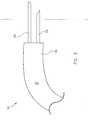
- Fig. 2is a perspective of a portion of the device shown in Fig. 1 .
- Fig. 3is a side view of the device shown in Fig. 1 .
- Fig. 4is a bottom plan of the device shown in Fig. 1 .
- Fig. 5is a perspective of a first embodiment of a medical device according to the present invention showing a mesh extending across the loop.
- Fig. 6is a perspective of a second embodiment of a medical device according to the present invention.
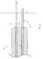
- Fig. 7is a cross-sectional side elevation of the embodiment of the medical device shown in Fig. 6 having a stored needle and ablating loop.
- Fig. 8is a cross-sectional side elevation of the embodiment of the medical device shown in Fig. 6 having a deployed needle and ablating loop.
- Fig. 9is a perspective of a third embodiment of a medical device according to the present invention.
- Fig. 10is a perspective of the embodiment of Fig. 9 having the applicator elements slidably disposed within the probe.
- Fig. 11is a perspective of a fourth embodiment of a medical device according to the present invention.
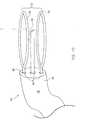
- Fig. 12is a perspective of a fifth embodiment of a medical device according to the present invention.
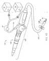
- Fig. 13is a perspective of the second embodiment of the device in combination with a conventional endoscope.
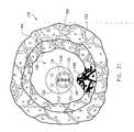
- Fig. 14is a perspective of a portion of the combination shown in Fig. 13 .
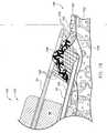
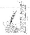
- Fig. 15is a cross-sectional front elevation of the combination shown in Fig. 14 positioned in a patient with applicator elements stored in the probe.
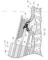
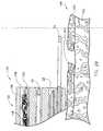
- Fig. 16is a cross-sectional side elevation of Fig. 15 shown after the needle has been inserted into the tissue.
- Fig. 17is the cross-sectional side elevation of Fig. 16 shown after fluid has been injected through the needle into the tissue.
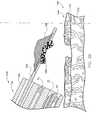
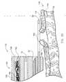
- Fig. 18is the cross-sectional side elevation of Fig. 17 shown during ablation of target tissue.
- Fig. 19is the cross-sectional side elevation of Fig. 18 shown after ablation of the target tissue and removal of the needle from the patient tissue.
- Fig. 20is a perspective of the fifth embodiment of the present invention in combination with a conventional endoscope.
- Fig. 21is a cross-sectional front elevation of Fig. 20 positioned in a patient with applicator elements stored in the probe.
- Fig. 22is a cross-sectional side elevation of the combination shown in Fig. 21 shown after the retainer, cutting loop, and needle have been deployed and the needle has been inserted into the tissue of the patient.
- Fig. 23is the cross section of Fig. 22 shown after fluid has been injected through the needle into the tissue.
- Fig. 24is the cross section of Fig. 23 shown after the needle has been retracted into the probe and the cutting loop and retainer have been positioned for cutting away and capturing the target tissue.
- Fig. 25is the cross section of Fig. 24 shown after the target tissue has been cut from the patient with the cutting loop.
- Fig. 26is the cross section of Fig. 25 shown during capture of the target tissue in the retainer.
- Fig. 27is the cross section of Fig. 26 shown after the target tissue has been captured in the retainer.
- Fig. 28is the cross section of Fig. 27 shown after the retainer has been retracted into the probe with the captured tissue.
- Fig. 29is the cross section of Fig. 28 shown after the ablating loop has been positioned adjacent edges of tissue remaining in the patient.
- Fig. 30is the cross section of Fig. 29 shown with the ablating loop directly contacting the edges of tissue remaining in the patient.
- Fig. 31is a perspective of the second embodiment of the device in combination with a conventional endoscope.
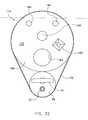
- Fig. 32is a front elevation of the combination shown in Fig. 31 .
- the present inventionrelates to a medical device for performing a therapeutic procedure on a patient, and more particularly a medical device for ablating and resecting unwanted tissue at a predetermined location within a patient.
- a medical deviceaccording to a first embodiment of the present invention is designated in its entirety by reference number 10.
- the medical device 10has an elongate probe 12 extending to an applicator end 14.
- Applicator elements 16are connected to the probe 12 adjacent the applicator end 14 of the probe.
- the probe 12may be made of other materials without departing from the scope of the present invention, in one embodiment the probe 12 is made of a flexible and thermally and/or electrically insulating material, such as silicone, polyethylene, or polypropylene.
- the probe 12is generally tubular. Further, although the probe may have other dimensions without departing from the scope of the present invention, in one embodiment the probe 12 has a maximum width 18 of between about 1 millimeter and about 5 millimeters . Having a maximum width 18 less than about 3 millimeters allows the probe 12 to fit inside the working channel of a standard endoscope (not shown in Figs. 1-12 ).
- the probemay have one or more traction elements 20, which increase the ability of a user to control the device 10.
- the applicator elements 16include an injection needle 22 connected to the probe 12 adjacent the applicator end 14 of the probe.
- the needle 22extends away from the probe 12 along a central axis 24.
- the needle 22may have other dimensions without departing from the scope of the present invention, in one embodiment the needle 22 has a maximum length 26 of between about 10 millimeters and about 20 millimeters and an outer diameter 28 of between about 0.5 millimeters and about 2 millimeters.
- the needle 22may be made of other materials without departing from the scope of the present invention, in one embodiment the needle 22 is made of any material traditionally used to make medical needles, such as 23 gage stainless steel.
- the needle 22is shown as being substantially straight, the needle may have other shapes without departing from the scope of the invention. For example, in one alternate embodiment the needle may be curved (not shown).
- the needle 22is communicatible with an energy source 30, as shown in Fig. 1 .
- the energy source 30delivers energy to the needle 22 during the therapeutic procedure.
- the energy source 30is an electrical generator for delivering electrical current to the needle 22.
- an electrical generatormay produce electrical current having other characteristics without departing from the scope of the present invention, in one embodiment it produces a current having a voltage of between about 10 volts and about 500 volts and a frequency of between about 0.3 megahertz and about 1.0 megahertz.
- the energy source 30is a radio frequency generator for delivering radio frequency energy to the needle 22.
- the radio frequency generatormay produce signals having other characteristics without departing from the scope of the present invention
- the radio frequency generatorproduces a signal having an amplitude of between about 10 volts and about 500 volts and a frequency of between about 0.3 megahertz and about 1.0 megahertz.
- the energy source 30delivers ultrasonic energy to the injection needle 22.
- the ultrasonic generatorproduces a signal having a frequency of between about 10 kilohertz and about 100 kilohertz.
- the needle 22also communicates with a fluid source 32, as shown in Fig. 1 .
- the fluid source 32delivers an electrically conductive fluid to the needle 22 during the therapeutic procedure.
- the fluid source 32is a conventional saline source for delivering saline to the needle 22.
- the fluid source 32may be a sclerotherapy agent (e.g., absolute ethanol) source for delivering sclerotherapy agent, such as absolute ethanol commonly used in hospitals, to the needle 22.
- the applicator elements 16also include an ablating loop 34 positioned adjacent the applicator end 14 of the probe 12.
- the ablating loop 34extends away from the probe 12 along a central axis 36.
- the central axis 24 of the needle 22 and the central axis 36 of the ablating loop 34may be spaced by other distances without departing from the scope of the present invention, in one embodiment the axes are spaced by a distance 38 of between about 2 millimeters and about 5 millimeters.
- the ablating loop 34 and the needle 22are substantially centered about the horizontal center of the probe 12.
- the ablating loop 34may have other dimensions without departing from the scope of the present invention, in one embodiment the ablating loop 34 has a length 40 of between about 10 millimeters and about 30 millimeters and a diameter 42 of between about 0.5 millimeters and about 1.5 millimeters. Further, although the ablating loop may be made of other materials without departing from the scope of the present invention, in one embodiment the ablating loop 34 is made of nitinol.
- the ablating loop 34 according to the present inventionincludes a conductive material positioned between sides 44, 46 of the loop forming a net or fine mesh 48, as shown in Fig. 5 .
- the mesh 48is made of stainless steel.
- the mesh 48ensures that the energy applied to the target tissue (not shown in Figs. 1-14 ) from the ablating loop 34 is more evenly distributed about the target tissue.
- the ablating loop 34may be shaped to facilitate connection with the mesh 48.
- the ablating loop 34can include hooks or openings (not shown) for connecting the mesh 48 to the loop.
- the ablating loop 34 and mesh 48can be fabricated together as one piece.
- the ablating loop 34is also connected to the energy source 30 for delivering energy to the ablating loop during the therapeutic procedure.
- the injection needle 22 and the ablating loop 34have opposite polarities when the medical device 10 is in use.
- the needle 22can have a charge opposite the charge of the ablating loop 34.
- Such bipolar energy transmissionis generally safer than mono-polar energy applications which can create coagulation zones that are too deep.
- the characteristics of the needle 22 and the ablating loop 34may change. That is, the characteristics for the needle 22 and ablating loop 34 may alternate or otherwise change with time during use of the medical instrument 10. Such varying signal characteristics, or multiplexing, results in higher levels of energy concentrated at and delivered from the needle 22 and ablating loop 34 as a result of the interaction of differing signals between the needle and ablating loop.
- Figs. 6-8show a second embodiment of a medical device 50 according to the present invention in which the injection needle 22 and ablating loop 34 are slidably disposed within respective channels 52, 54 of the elongate probe 56.
- the needle 22 and the ablating loop 34can be moved between multiple positions.
- Fig. 7shows the needle 22 and ablating loop 34 in stored positions in which the needle and ablating loop are recessed in the probe 56.
- Fig. 8shows the needle 22 and ablating loop 34 in deployed positions in which the needle and ablating loop extend beyond the face 60 of the applicator end 58 of the probe 56.
- the needle 22extends out of the probe 56 at an angle ⁇ with the face 60 of the applicator end 58 of the probe.
- Fig. 8shows an angle ⁇ of approximately 90 degrees
- the needlemay extend from the probe face at other angles without departing from the scope of the present invention.
- the needle 22may move out of the probe at an angle ⁇ of between about 60 degrees and about 90 degrees.
- the needle 22 and ablating loop 34are otherwise identical to the needle and ablating loop of the first embodiment, and therefore will not be described in further detail.
- Fig. 9shows a third embodiment of a medical device 70 according to the present invention wherein applicator elements 72 include a cutting loop 74 attached to an applicator end 76 of a probe 78.
- the cutting loopmay have other dimensions without departing from the scope of the present invention, in one embodiment the cutting loop 74 has a diameter 80 of between about 0.5 millimeters and about 1.5 millimeters and an exposed length 82 of between about 10 millimeters and about 30 millimeters.
- the cutting loopmay be made of other materials without departing from the scope of the present invention, in one embodiment the cutting loop 74 is made of stainless steel.
- the applicator elements 72may be slidably disposed within respective channels 84 in the probe 78, as shown in Fig. 10 .
- each of the applicator elements 72can be moved between a deployed position, shown in Fig. 10 , in which the elements 72 extend beyond a face 86 of the end 76 of the probe 78, and a stored position (not shown) in which the elements are fully disposed within the probe 78. Further, each of the elements 72 may be independently moved between their respective stored and deployed positions.
- Fig. 9shows the needle 22 positioned between the ablating loop 34 and cutting loop 74, these elements may be arranged in other ways without departing from the scope of the present invention. For example, Fig.
- FIG. 11shows a fourth embodiment of a medical device 90 according to the present invention having the cutting loop 74 positioned adjacent an applicator end 92 of a probe 94 between the needle 22 and the ablating loop 34.
- Fig. 9shows each of the applicator elements 72 fixedly connected to the probe 78 and Figs. 10 and 11 show each of the applicator elements slidably disposed within the probe, each of these elements 72 may relate to the probe 78, 94 in either manner.
- the needle 22is fixedly connected to the probe 78, 94 and the ablating and cutting loops 34, 74 are slidably disposed within the probe 78, 94.
- the probe 94, needle 22, and ablating loop 34 of the embodiments described in this paragraphare otherwise identical to those of the earlier described embodiments, and therefore will not be described in further detail.
- Fig. 12shows a fifth embodiment of a medical device 100 according to the present invention having a retainer 102 attached to an applicator end 104 of a probe 106 to capture and hold tissue cut from the patient (not shown in Figs. 1-14 ).
- Applicator elements 110may be slidably disposed within the probe 106, as shown in Fig. 12 . Thus, each of the applicator elements 110 can be moved between a deployed position, in which the applicator elements extend beyond the end 104 of the probe 106, and a stored position (shown in Fig. 21 ) in which the applicator elements are recessed within the probe 106.
- the needle 22 and cutting loop 74are shown in Fig.
- the retainer 12in an intermediate position between the stored and deployed positions and the ablating loop 34 and retainer 102 are shown in a deployed position. Further, each of the elements 110 may be independently moved between their respective stored and deployed positions.
- the retainermay be configured otherwise without departing from the scope of the present invention, in one embodiment the retainer 102 comprises netting 108 attached to the body of the retainer 102. Although the retainer may have other dimensions without departing from the scope of the present invention, in one embodiment the retainer 102 has an exposed length 112 of between about 10 millimeters and 30 millimeters and a body thickness 114 of between about 0.5 millimeters and about 1.5 millimeters.
- the net 108has a depth 116 of between about 1 millimeter and about 5 millimeters.
- the retainer 102may be configured to capture and hold the resected tissue in other ways without departing from the scope of the present invention.
- the retainer 102may be connected to a suction source (not shown) to attract and retain the resected tissue by aspiration.
- the probe 106, needle 22, ablating loop 34, and cutting loop 74 of this embodimentare otherwise identical to those of the earlier described embodiments, and therefore will not be described in further detail.
- Fig. 13shows an embodiment of a medical device 120 according to the present invention including an endoscope 122.
- the endoscope 122may be a flexible endoscope, such as those commonly used in upper gastrointestinal endoscopy examinations, or esophagogastroduodenoscopy (EGD).
- the endoscope 122has an elongate primary body 124 and an elongate tubular portion 126 (e.g., a flexible shaft) extending from the body 124 to a working end 128.
- the endoscope 122also has a working channel 130 beginning at an entry orifice 132 on the primary body 124 and terminating at a terminal port 134 at an extreme end 136 of the shaft 126.
- the working channel of conventional endoscopeshas a diameter, or minimum width if non-circular, of about three millimeters.
- the probe 56, needle 22, and ablating loop 34are sized and shaped for slidable receipt within the working channel 130 of the endoscope 122.
- the probe 56, needle 22, and ablating loop 34 of this embodimentare otherwise identical to those of the earlier described embodiments, and therefore will not be described in further detail.
- the medical device 120can have viewing optics 138 for viewing an object (not shown) positioned in a viewing area (not shown) adjacent the working end 128 of the endoscope 122.
- the viewing areacomprises all the objects visible through the viewing optics 138, including the applicator elements 16 and adjacent patient tissue (not shown in Figs. 1-14 ). Although the viewing area may have other shapes without departing from the scope of the present invention, in one embodiment the area is circular.
- the optics 138are disposed within the endoscope 122, beginning at a location (not shown) adjacent the primary body 124, where a user may receive images, and terminating adjacent an optics orifice 140.
- the endoscope 122can also have a cleaning tab 141 for cleaning the optics 138 by forcing fluid against a lens (not shown) covering an end of the optics adjacent the working end 128 of the endoscope.
- the cleaning tab 141may be made of other materials without departing from the scope of the present invention, in one embodiment the cleaning tab is made of metal.
- the cleaning tab 141can be connected to the same fluid source 32 connected to the needle 22 or a separate fluid source (not shown) for delivering fluid to the cleaning tab during operation of the device 120.
- the cleaning tab 141may force other fluids against the lens of the optics 138 without departing from the scope of the present invention, in one embodiment the cleaning tab forces water against the lens.
- the endoscope 122also has an illuminator 142 for directing light toward an object (not shown) positioned adjacent the working end 128 of the shaft 126. As with the optics 138, the illuminator 142 originates at a location (not shown) adjacent the primary body 124 and terminates adjacent the extreme end 136 of the shaft 126.
- a primary purpose for the medical deviceis to ablate and/or remove unwanted abnormal tissue growths.
- the medical deviceis described as ablating and removing abnormal gastrointestinal polyps and lesions in humans, the device may ablate other tissues, tissues in other animals, or things other than tissue without departing from the scope of the present invention.
- a user of the medical device 120first positions the elongate probe 56 in the working channel 130 of the endoscope 122.
- the injection needle 22 and ablating loop 34are connected to an energy source 30 and the injection needle 22 is further connected to a fluid source 32.
- the probe 56, needle 22, ablating loop 34, and energy source 30can be the same as any of the earlier described embodiments, and therefore will not be described in further detail.
- Fig. 15shows the probe 56 slidably disposed in the working channel 130 of the endoscope 122 and the endoscope/probe combination disposed within a cavity or lumen 144 such as an esophagus of a patient 146.
- the usermoves the endoscope 122 and probe 56 to a predetermined location within the patient 146.
- Positioning the endoscope 122 and probe 56may include articulating the shaft 126 of the endoscope 122, translating the endoscope 122, rotating the probe 56 with respect to the endoscope 122, and/or translating the probe 56 with respect to the endoscope 122.
- the userdeploys the needle 22 such that the needle extends through the port 134 of the working channel 130 at the working end 128 of the endoscope 122.
- the useralso deploys the ablating loop 34 such that the loop 34 extends through the port 134 of the endoscope 122.
- the usermay deploy the ablating loop 34 at the same time as, before, or after the needle 22 is deployed.
- the usercauses the needle 22 to contact the patient 146 adjacent the abnormal growth 148 and advance below an inner or mucosal layer 150 of the lumen 144.
- it is preferred that the needle 22is forced to a position between the inner layer 150 and a muscular layer 152 underlying the inner layer 150, as shown in Fig. 16 .
- fluid 154is injected into the lumen 144 through the needle 22, thereby causing the inner layer 150 adjacent the abnormal growth 148 to move away from the muscular layer 152, as shown in Fig. 17 .
- the usercan destroy the targeted tissue 148 of the patient 146 located between the needle 22 is forced below the inner layer 150, fluid 154 is injected into the lumen 144 through the needle 22, thereby causing the inner layer 150 adjacent the abnormal growth 148 to move away from the muscular layer 152, as shown in Fig. 17 .
- the usercan destroy the targeted tissue 148 of the patient 146 located between the needle 22 and ablating loop 34 by simultaneously energizing the needle and ablating loop thereby causing energy 158 to transfer through the target tissue, as shown in Fig. 18 .
- the injection needle 22 and the ablating loop 34can carry opposite polarities. Further, the polarities of the needle 22 and ablating loop 34 can change with time.
- healthy adjacent tissue 156 of the inner layer 150is substantially unharmed because the energy transmission focuses between the needle 22 and ablating loop 34, where the diseased tissue 148 is located but the healthy adjacent tissue is not.
- the healthy underlying tissue 152is also substantially unharmed during ablation because the injection of fluid into the lumen 144 causes the muscular tissue 152 to be spaced from the target tissue 148 and the energy transmission focuses between the needle 22 and the ablating loop 34.
- the usercan remove the needle 22 from the patient 146, as shown in Fig. 19 .
- the destroyed tissue 160will be sloughed off (i.e., through the normal digestive process) and healthy mucosal tissue 150 will grow in its place.
- the destroyed tissue 160may be resected after ablation.
- the destroyed tissuemay be captured and held in the retainer 102 after being cut from the patient with the cutting loop 74.
- Fig. 20shows an embodiment of a medical device 170 according to the present invention including an endoscope 122.
- a userpositions an elongate probe 106 having a needle 22, ablating loop 34, cutting loop 74, and retainer 102 in the working channel 130 of the endoscope 122.
- the injection needle 22 and ablating loop 34are connected to an energy source 30 and the injection needle 22 is further connected to a fluid source 32.
- the endoscope 122, probe 106, needle 22, cutting loop 74, retainer 102, ablating loop 34, and energy source 30can be the same as any of the earlier described embodiments, and therefore will not be described in further detail.
- FIG. 21shows the probe 106 slidably disposed in the working channel 130 of the endoscope 122 and the endoscope/probe combination disposed within a lumen 144 of a patient 146. The user then moves the endoscope 122 and probe 106 to a predetermined location adjacent abnormal tissue growth 148 as described regarding earlier embodiments.
- the userdeploys the needle 22 such that the needle extends through the port 134 of the working channel 130 at the working end 128 of the endoscope 122.
- the useralso deploys the cutting loop 74 such that the cutting loop 74 extends through the port 134 of the endoscope 122.
- the userdeploys the retainer 102 such that the retainer 102 also extends through the port 134 of the endoscope 122.
- the usermay deploy the applicator elements 110 in any order and may deploy some or all of the elements 110 simultaneously.
- the needle 22, cutting loop 74, and retainer 102can be deployed simultaneously before the ablating loop 34 is deployed.
- the usercauses the needle 22 to contact the patient 146 adjacent the abnormal growth 148 and advance below the inner layer 150 of the lumen 144.
- the needle 22is forced to a position between the inner layer 150 and the muscular layer 152 underlying the inner layer 150, as shown in Fig. 22 .
- fluid 154is injected into the lumen 144 through the needle 22, thereby causing the inner layer 150 adjacent the abnormal growth 148 to move away from the muscular layer 152, as shown in Fig. 23 . Spacing the abnormal growth above the muscular layer 152 by injecting fluid 154 facilitates accurate cutting away of the abnormal tissue 148 without adversely affecting adjacent and underlying healthy tissue 156, 152.
- isolating the unwanted tissue 148 from the healthy tissue 156, 152allows the user to resect a larger amount of tissue than can be safely resected without such isolation.
- the usercan remove the needle from the tissue of the lumen 144, position the cutting loop 74 to cut the abnormal growth 148 from the patient, and position the retainer 102 to capture and hold the growth 148 after it is cut.
- Fig. 24shows an example of such positioning of the cutting loop 74 and retainer 102.
- Positioning the cutting loop 74 for cutting the growth 148includes surrounding the growth 14 with the cutting loop 74.
- Positioning the retainer 102 for capturing the growth 148includes positioning the retainer 102 such that the growth 128 will naturally fall into the net 108 of the retainer after it is cut from the patient 146 or such that the retainer 102 can be maneuvered to capture the growth 148 after it is cut from the patient 146.
- the cutting loop 74 and retainer 102are positioned for cutting and capturing as described, the cutting loop 74 is withdrawn into the probe 106 thereby cutting the abnormal growth 148 from the patient 146, as shown in Fig. 25 .
- the retainercan be maneuvered to capture the growth 148, as exemplified in Figs. 26 and 27 .
- the retaineris withdrawn into the probe 106, as shown in Figs. 27 and 28 . In this way, the abnormal growth 148 can be removed from the patient for analysis.
- the usermay desire to ablate at least the edges 162 of tissue 150 remaining in the patient.
- the userextends the ablating loop 34 and positions the loop 34 adjacent the edges 162, as shown in Fig. 29 . Then, the user transfers energy from the ablating loop 34 to the edges 162 of tissue to ablate the edges 162.
- the ablating loopcan be placed in direct contact with the tissue 150 adjacent the edges 162, as shown in Fig. 30 .
- diseased mucosal tissue 148can be resected and removed from a patient for analysis and healthy adjacent mucosal tissue 156 and underlying muscular tissue 152 are substantially unharmed. Further, edges 162 of tissue 150 remaining in the patient 146 after the resection can be ablated through the application of energy thereto.
- medical device 170it will be appreciated by those skilled in the art that other disclosed embodiments can be used in a substantially similar manner. Further, the steps disclosed for using the device may be selectively performed, and in various order. For instance, although one embodiment includes a cutting step before an ablating step, a user can ablate before and/or after the cutting step.
- Fig. 31shows an embodiment of a medical device 172 according to the present invention including an endoscope 174.
- the probe 56is connected to the exterior of the shaft 176 of endoscope 174.
- Figs. 31 and 32show a probe 56 according to the second embodiment of the present invention connected to the endoscope 174, other embodiments of the probe may be connected to the endoscope without departing from the scope of the present invention.
- the probe 56may be connected to the endoscope 174 in other ways without departing from the scope of the present invention, in one embodiment the endoscope 174 is connected to the probe 56 by a flexible sleeve 178.
- the sleeve 178may be made of other materials without departing from the scope of the present invention, in one embodiment the sleeve is made of rubber.
- the probe 56can be connected to the shaft 176 of the endoscope 174 by a rigid tube. In one embodiment, it is preferred that the probe 56 have a smooth exterior surface 180.
- One of the benefits of connecting the probe 56 to the exterior of the endoscope 174is that the probe does not need to be sized to fit within the working channel 182 (shown in Fig. 32 ).
- the endoscope 174can have a plurality of illuminators 184 for directing light toward an object (not shown) positioned adjacent the working end 186 of the shaft in a viewing area (not shown).
- the endoscope 174can also have viewing optics 188 for viewing the object and a cleaning tab 190 for cleaning the optics.
- the medical device 172 and use thereofare otherwise the same as any of the earlier described embodiments, and therefore will not be described in further detail.
- the devicemay also be used on materials other than tissue. In view of the above, it will be seen that the several objects of the invention are achieved.
Landscapes
- Health & Medical Sciences (AREA)
- Surgery (AREA)
- Engineering & Computer Science (AREA)
- Life Sciences & Earth Sciences (AREA)
- Biomedical Technology (AREA)
- Molecular Biology (AREA)
- Nuclear Medicine, Radiotherapy & Molecular Imaging (AREA)
- Plasma & Fusion (AREA)
- Physics & Mathematics (AREA)
- Heart & Thoracic Surgery (AREA)
- Medical Informatics (AREA)
- Otolaryngology (AREA)
- Animal Behavior & Ethology (AREA)
- General Health & Medical Sciences (AREA)
- Public Health (AREA)
- Veterinary Medicine (AREA)
- Surgical Instruments (AREA)
- Endoscopes (AREA)
Description
- The present invention relates to a medical device, and more particularly to an ablation and resection device for performing therapy on a patient therewith.
- Various devices and methods have been traditionally used to ablate or remove unwanted polyps, tumors, lesions, and similar abnormal growths located within a patient cavity. An example of such abnormal growths is pre-cancerous polyps or tumors that commonly develop in the glands and cells that line the colon and rectum. Other examples of abnormal growths include polypoid lesions or esophageal squamous papilloma, which are rare benign tumors of the upper gastrointestinal tract, and neoplasms of the esophagus. If not removed or destroyed, such abnormal growths often advance to more severe stages and create complications in the patient. For example, malignant tumors may spread within the body beyond their original location and create life threatening conditions.
- Common methods for treating abnormal intracavital growths include resection, cryotherapy, and thermal therapy. Resection, also known as excision, is the cutting of unwanted growth from the patient. For resection methods that include capture of the tissue cut away from the patient, benefits include the patient being immediately free of the unwanted tissue and the ability to analyze the removed tissue in the laboratory. Cryotherapy, also known as cryoablation, is the application of extreme cold to freeze and destroy unwanted tissue. For example, liquid nitrogen or liquid argon are used to supercool probes used to freeze unwanted tissue. Thermal therapy, also known as thermal ablation and heat ablation, is the application of heat to coagulate, cauterize and/or ablate diseased mucosal tissue. The most common form of thermal ablation is radiofrequency ablation where radiofrequency energy is applied to the unwanted tissue. Other heat therapies include microwave coagulonecrotic therapy, laser therapy, and high intensity focused ultrasound. In cryotherapy and thermal therapy, sufficient raising or lowering of tissue temperature, respectively causes necrosis of the effected tissue. For convenience, the term ablate will be used herein to describe any and all of these thermal therapy processes. In use, these devices are placed adjacent the unwanted tissue and tissue is ablated, cauterized, coagulated, frozen, or burnt, as the case may be, by energy transmitted from or to the device.
US patent 5,846,248 discloses a medical device for removing intracavital growth comprising the features of the preamble ofclaim 1.US patent 6,007,546 discloses a medical device for removing intracavital growth comprising an injection needle comprised of an electrically conductive material and a cauterization loop utilized to capture a polyp within the loop and cut the polyp from the body, wherein the loop is attached to the needle by an electrically conducting connection joint.- Traditional treatment devices have three primary shortcomings. First, traditional devices can ablate or resect only relatively small portions of patient tissue at one time. For example, ablation devices having a surface for ablating patient tissue by transmitting energy to or from the surface can only ablate an area of patient tissue substantially equal to the area of the transmission surface in a single energy transmission.
- A second primary shortcoming of traditional treatment devices is their inaccuracy in use. A primary challenge for treating unwanted growths is to destroy or resect the targeted tissue without adversely affecting healthy adjacent or underlying cells. Regarding ablation devices especially, damage to healthy underlying esophageal muscle tissue often leads to the creation of a stricture or constriction in the esophagus. Many traditional ablation devices ablate targeted tissue without first isolating the targeted tissue from adjacent and underlying healthy tissue. As a result, when too much energy is transferred to or from the device, ablation of healthy adjacent cells and/or underlying cells can occur. On the other hand, when too little energy is transferred from the device, less than all of the targeted tissue is treated.
- A third primary shortcoming of traditional devices is present with devices having resecting capability. Use of conventional resection devices allows for resection of tissue from a patient, but leaves non-cauterized, or insufficiently cauterized tissue in the patient. Non-cauterized or insufficiently cauterized tissue remaining in the patient after a resection may lead to infection or bleeding.
- The conventional approaches for treating unwanted and abnormal growths requiring the precise resection and/or ablation of relatively large portions of intralumenal tissue are insufficient in these regards. Thus, there is a need for a resection and ablation device and a method for using such a device that allow accurate and minimally invasive resection and ablation, as the case may be, of relatively large amounts of intralumenal patient tissue.
- The present invention provides a medical device according to
claim 1. The dependent claims set out optional features. - Other aspects of the present invention will be in part apparent and in part pointed out hereinafter.
Fig. 1 is a perspective of a first embodiment of a medical device according to the present invention.Fig. 2 is a perspective of a portion of the device shown inFig. 1 .Fig. 3 is a side view of the device shown inFig. 1 .- 15
Fig. 4 is a bottom plan of the device shown inFig. 1 . Fig. 5 is a perspective of a first embodiment of a medical device according to the present invention showing a mesh extending across the loop.Fig. 6 is a perspective of a second embodiment of a medical device according to the present invention.Fig. 7 is a cross-sectional side elevation of the embodiment of the medical device shown inFig. 6 having a stored needle and ablating loop.Fig. 8 is a cross-sectional side elevation of the embodiment of the medical device shown inFig. 6 having a deployed needle and ablating loop.Fig. 9 is a perspective of a third embodiment of a medical device according to the present invention.Fig. 10 is a perspective of the embodiment ofFig. 9 having the applicator elements slidably disposed within the probe.Fig. 11 is a perspective of a fourth embodiment of a medical device according to the present invention.Fig. 12 is a perspective of a fifth embodiment of a medical device according to the present invention.Fig. 13 is a perspective of the second embodiment of the device in combination with a conventional endoscope.Fig. 14 is a perspective of a portion of the combination shown inFig. 13 .Fig. 15 is a cross-sectional front elevation of the combination shown inFig. 14 positioned in a patient with applicator elements stored in the probe.Fig. 16 is a cross-sectional side elevation ofFig. 15 shown after the needle has been inserted into the tissue.Fig. 17 is the cross-sectional side elevation ofFig. 16 shown after fluid has been injected through the needle into the tissue.Fig. 18 is the cross-sectional side elevation ofFig. 17 shown during ablation of target tissue.Fig. 19 is the cross-sectional side elevation ofFig. 18 shown after ablation of the target tissue and removal of the needle from the patient tissue.Fig. 20 is a perspective of the fifth embodiment of the present invention in combination with a conventional endoscope.Fig. 21 is a cross-sectional front elevation ofFig. 20 positioned in a patient with applicator elements stored in the probe.Fig. 22 is a cross-sectional side elevation of the combination shown inFig. 21 shown after the retainer, cutting loop, and needle have been deployed and the needle has been inserted into the tissue of the patient.Fig. 23 is the cross section ofFig. 22 shown after fluid has been injected through the needle into the tissue.Fig. 24 is the cross section ofFig. 23 shown after the needle has been retracted into the probe and the cutting loop and retainer have been positioned for cutting away and capturing the target tissue.Fig. 25 is the cross section ofFig. 24 shown after the target tissue has been cut from the patient with the cutting loop.Fig. 26 is the cross section ofFig. 25 shown during capture of the target tissue in the retainer.Fig. 27 is the cross section ofFig. 26 shown after the target tissue has been captured in the retainer.Fig. 28 is the cross section ofFig. 27 shown after the retainer has been retracted into the probe with the captured tissue.Fig. 29 is the cross section ofFig. 28 shown after the ablating loop has been positioned adjacent edges of tissue remaining in the patient.Fig. 30 is the cross section ofFig. 29 shown with the ablating loop directly contacting the edges of tissue remaining in the patient.Fig. 31 is a perspective of the second embodiment of the device in combination with a conventional endoscope.Fig. 32 is a front elevation of the combination shown inFig. 31 .- Corresponding reference characters indicate corresponding parts throughout the several views of the drawings.
- The present invention relates to a medical device for performing a therapeutic procedure on a patient, and more particularly a medical device for ablating and resecting unwanted tissue at a predetermined location within a patient. Referring now to the figures, and more particularly to
Fig. 1 , a medical device according to a first embodiment of the present invention is designated in its entirety byreference number 10. Themedical device 10 has anelongate probe 12 extending to anapplicator end 14.Applicator elements 16 are connected to theprobe 12 adjacent theapplicator end 14 of the probe. Although the probe may be made of other materials without departing from the scope of the present invention, in one embodiment theprobe 12 is made of a flexible and thermally and/or electrically insulating material, such as silicone, polyethylene, or polypropylene. Although the probe may have other shapes without departing from the scope of the present invention, in one embodiment theprobe 12 is generally tubular. Further, although the probe may have other dimensions without departing from the scope of the present invention, in one embodiment theprobe 12 has amaximum width 18 of between about 1 millimeter and about 5 millimeters . Having amaximum width 18 less than about 3 millimeters allows theprobe 12 to fit inside the working channel of a standard endoscope (not shown inFigs. 1-12 ). The probe may have one ormore traction elements 20, which increase the ability of a user to control thedevice 10. - As shown in
Fig. 2 , theapplicator elements 16 include aninjection needle 22 connected to theprobe 12 adjacent theapplicator end 14 of the probe. Theneedle 22 extends away from theprobe 12 along acentral axis 24. Although the needle may have other dimensions without departing from the scope of the present invention, in one embodiment theneedle 22 has amaximum length 26 of between about 10 millimeters and about 20 millimeters and anouter diameter 28 of between about 0.5 millimeters and about 2 millimeters. Also, although the needle may be made of other materials without departing from the scope of the present invention, in one embodiment theneedle 22 is made of any material traditionally used to make medical needles, such as 23 gage stainless steel. Further, although theneedle 22 is shown as being substantially straight, the needle may have other shapes without departing from the scope of the invention. For example, in one alternate embodiment the needle may be curved (not shown). - The
needle 22 is communicatible with anenergy source 30, as shown inFig. 1 . Theenergy source 30 delivers energy to theneedle 22 during the therapeutic procedure. Although other energy sources may be used without departing from the scope of the present invention, in one embodiment theenergy source 30 is an electrical generator for delivering electrical current to theneedle 22. Although such an electrical generator may produce electrical current having other characteristics without departing from the scope of the present invention, in one embodiment it produces a current having a voltage of between about 10 volts and about 500 volts and a frequency of between about 0.3 megahertz and about 1.0 megahertz. In another embodiment, theenergy source 30 is a radio frequency generator for delivering radio frequency energy to theneedle 22. Although such a radio frequency generator may produce signals having other characteristics without departing from the scope of the present invention, in one embodiment the radio frequency generator produces a signal having an amplitude of between about 10 volts and about 500 volts and a frequency of between about 0.3 megahertz and about 1.0 megahertz. In a background example, theenergy source 30 delivers ultrasonic energy to theinjection needle 22. Although such an ultrasonic generator may produce signals having other frequencies, the ultrasonic generator produces a signal having a frequency of between about 10 kilohertz and about 100 kilohertz. - The
needle 22 also communicates with afluid source 32, as shown inFig. 1 . Thefluid source 32 delivers an electrically conductive fluid to theneedle 22 during the therapeutic procedure. Although other fluid sources may be used without departing from the scope of the present invention, in one embodiment thefluid source 32 is a conventional saline source for delivering saline to theneedle 22. Alternatively, thefluid source 32 may be a sclerotherapy agent (e.g., absolute ethanol) source for delivering sclerotherapy agent, such as absolute ethanol commonly used in hospitals, to theneedle 22. - The
applicator elements 16 also include anablating loop 34 positioned adjacent theapplicator end 14 of theprobe 12. Theablating loop 34 extends away from theprobe 12 along acentral axis 36. Although thecentral axis 24 of theneedle 22 and thecentral axis 36 of theablating loop 34 may be spaced by other distances without departing from the scope of the present invention, in one embodiment the axes are spaced by adistance 38 of between about 2 millimeters and about 5 millimeters. As shown inFig. 4 , theablating loop 34 and theneedle 22 are substantially centered about the horizontal center of theprobe 12. Although theablating loop 34 may have other dimensions without departing from the scope of the present invention, in one embodiment theablating loop 34 has alength 40 of between about 10 millimeters and about 30 millimeters and adiameter 42 of between about 0.5 millimeters and about 1.5 millimeters. Further, although the ablating loop may be made of other materials without departing from the scope of the present invention, in one embodiment theablating loop 34 is made of nitinol. Theablating loop 34 according to the present invention includes a conductive material positioned betweensides fine mesh 48, as shown inFig. 5 . Although the mesh may be made of other materials without departing from the scope of the present invention, in one embodiment themesh 48 is made of stainless steel. Themesh 48 ensures that the energy applied to the target tissue (not shown inFigs. 1-14 ) from the ablatingloop 34 is more evenly distributed about the target tissue. Theablating loop 34 may be shaped to facilitate connection with themesh 48. For example, theablating loop 34 can include hooks or openings (not shown) for connecting themesh 48 to the loop. Alternatively, theablating loop 34 andmesh 48 can be fabricated together as one piece. Theablating loop 34 is also connected to theenergy source 30 for delivering energy to the ablating loop during the therapeutic procedure. - In one embodiment of the present invention, the
injection needle 22 and theablating loop 34 have opposite polarities when themedical device 10 is in use. For example, with either the radio frequency or theelectrical power generators 30, theneedle 22 can have a charge opposite the charge of theablating loop 34. Such bipolar energy transmission is generally safer than mono-polar energy applications which can create coagulation zones that are too deep. Also, the characteristics of theneedle 22 and theablating loop 34 may change. That is, the characteristics for theneedle 22 and ablatingloop 34 may alternate or otherwise change with time during use of themedical instrument 10. Such varying signal characteristics, or multiplexing, results in higher levels of energy concentrated at and delivered from theneedle 22 and ablatingloop 34 as a result of the interaction of differing signals between the needle and ablating loop. Figs. 6-8 show a second embodiment of amedical device 50 according to the present invention in which theinjection needle 22 and ablatingloop 34 are slidably disposed withinrespective channels elongate probe 56. In this embodiment, theneedle 22 and theablating loop 34 can be moved between multiple positions. For example,Fig. 7 shows theneedle 22 and ablatingloop 34 in stored positions in which the needle and ablating loop are recessed in theprobe 56.Fig. 8 shows theneedle 22 and ablatingloop 34 in deployed positions in which the needle and ablating loop extend beyond theface 60 of theapplicator end 58 of theprobe 56. Theneedle 22 extends out of theprobe 56 at an angle θ with theface 60 of theapplicator end 58 of the probe. AlthoughFig. 8 shows an angle θ of approximately 90 degrees, the needle may extend from the probe face at other angles without departing from the scope of the present invention. For example, theneedle 22 may move out of the probe at an angle θ of between about 60 degrees and about 90 degrees. Theneedle 22 and ablatingloop 34 are otherwise identical to the needle and ablating loop of the first embodiment, and therefore will not be described in further detail.Fig. 9 shows a third embodiment of amedical device 70 according to the present invention whereinapplicator elements 72 include a cuttingloop 74 attached to anapplicator end 76 of aprobe 78. Although the cutting loop may have other dimensions without departing from the scope of the present invention, in one embodiment the cuttingloop 74 has adiameter 80 of between about 0.5 millimeters and about 1.5 millimeters and an exposedlength 82 of between about 10 millimeters and about 30 millimeters. Further, although the cutting loop may be made of other materials without departing from the scope of the present invention, in one embodiment the cuttingloop 74 is made of stainless steel. Theapplicator elements 72 may be slidably disposed withinrespective channels 84 in theprobe 78, as shown inFig. 10 . Thus, each of theapplicator elements 72 can be moved between a deployed position, shown inFig. 10 , in which theelements 72 extend beyond aface 86 of theend 76 of theprobe 78, and a stored position (not shown) in which the elements are fully disposed within theprobe 78. Further, each of theelements 72 may be independently moved between their respective stored and deployed positions. AlthoughFig. 9 shows theneedle 22 positioned between the ablatingloop 34 and cuttingloop 74, these elements may be arranged in other ways without departing from the scope of the present invention. For example,Fig. 11 shows a fourth embodiment of amedical device 90 according to the present invention having the cuttingloop 74 positioned adjacent anapplicator end 92 of aprobe 94 between theneedle 22 and theablating loop 34. Also, althoughFig. 9 shows each of theapplicator elements 72 fixedly connected to theprobe 78 andFigs. 10 and11 show each of the applicator elements slidably disposed within the probe, each of theseelements 72 may relate to theprobe needle 22 is fixedly connected to theprobe loops probe probe 94,needle 22, and ablatingloop 34 of the embodiments described in this paragraph are otherwise identical to those of the earlier described embodiments, and therefore will not be described in further detail.Fig. 12 shows a fifth embodiment of amedical device 100 according to the present invention having aretainer 102 attached to anapplicator end 104 of aprobe 106 to capture and hold tissue cut from the patient (not shown inFigs. 1-14 ).Applicator elements 110 may be slidably disposed within theprobe 106, as shown inFig. 12 . Thus, each of theapplicator elements 110 can be moved between a deployed position, in which the applicator elements extend beyond theend 104 of theprobe 106, and a stored position (shown inFig. 21 ) in which the applicator elements are recessed within theprobe 106. Theneedle 22 and cuttingloop 74 are shown inFig. 12 in an intermediate position between the stored and deployed positions and theablating loop 34 andretainer 102 are shown in a deployed position. Further, each of theelements 110 may be independently moved between their respective stored and deployed positions. Although the retainer may be configured otherwise without departing from the scope of the present invention, in one embodiment theretainer 102 comprises netting 108 attached to the body of theretainer 102. Although the retainer may have other dimensions without departing from the scope of the present invention, in one embodiment theretainer 102 has an exposedlength 112 of between about 10 millimeters and 30 millimeters and abody thickness 114 of between about 0.5 millimeters and about 1.5 millimeters. Further, although the net may have other depths without departing from the scope of the present invention, in one embodiment the net 108 has adepth 116 of between about 1 millimeter and about 5 millimeters. Instead of having a net 108, theretainer 102 may be configured to capture and hold the resected tissue in other ways without departing from the scope of the present invention. For example, in one embodiment (not shown) theretainer 102 may be connected to a suction source (not shown) to attract and retain the resected tissue by aspiration. Theprobe 106,needle 22, ablatingloop 34, and cuttingloop 74 of this embodiment are otherwise identical to those of the earlier described embodiments, and therefore will not be described in further detail.Fig. 13 shows an embodiment of amedical device 120 according to the present invention including anendoscope 122. AlthoughFig. 13 shows one type ofendoscope 122, any conventional type of endoscope may be used without departing from the scope of the present invention. Theendoscope 122 may be a flexible endoscope, such as those commonly used in upper gastrointestinal endoscopy examinations, or esophagogastroduodenoscopy (EGD). Theendoscope 122 has an elongateprimary body 124 and an elongate tubular portion 126 (e.g., a flexible shaft) extending from thebody 124 to a workingend 128. Theendoscope 122 also has a workingchannel 130 beginning at anentry orifice 132 on theprimary body 124 and terminating at aterminal port 134 at anextreme end 136 of theshaft 126. The working channel of conventional endoscopes has a diameter, or minimum width if non-circular, of about three millimeters. In one embodiment of the present invention, theprobe 56,needle 22, and ablatingloop 34 are sized and shaped for slidable receipt within the workingchannel 130 of theendoscope 122. Theprobe 56,needle 22, and ablatingloop 34 of this embodiment are otherwise identical to those of the earlier described embodiments, and therefore will not be described in further detail.- As shown in
Fig. 14 , themedical device 120 can haveviewing optics 138 for viewing an object (not shown) positioned in a viewing area (not shown) adjacent the workingend 128 of theendoscope 122. The viewing area comprises all the objects visible through theviewing optics 138, including theapplicator elements 16 and adjacent patient tissue (not shown inFigs. 1-14 ). Although the viewing area may have other shapes without departing from the scope of the present invention, in one embodiment the area is circular. Theoptics 138 are disposed within theendoscope 122, beginning at a location (not shown) adjacent theprimary body 124, where a user may receive images, and terminating adjacent anoptics orifice 140. Theendoscope 122 can also have acleaning tab 141 for cleaning theoptics 138 by forcing fluid against a lens (not shown) covering an end of the optics adjacent the workingend 128 of the endoscope. Although thecleaning tab 141 may be made of other materials without departing from the scope of the present invention, in one embodiment the cleaning tab is made of metal. Thecleaning tab 141 can be connected to thesame fluid source 32 connected to theneedle 22 or a separate fluid source (not shown) for delivering fluid to the cleaning tab during operation of thedevice 120. Although thecleaning tab 141 may force other fluids against the lens of theoptics 138 without departing from the scope of the present invention, in one embodiment the cleaning tab forces water against the lens. Theendoscope 122 also has anilluminator 142 for directing light toward an object (not shown) positioned adjacent the workingend 128 of theshaft 126. As with theoptics 138, theilluminator 142 originates at a location (not shown) adjacent theprimary body 124 and terminates adjacent theextreme end 136 of theshaft 126. - A primary purpose for the medical device is to ablate and/or remove unwanted abnormal tissue growths. Although the medical device is described as ablating and removing abnormal gastrointestinal polyps and lesions in humans, the device may ablate other tissues, tissues in other animals, or things other than tissue without departing from the scope of the present invention.
- In operation, a user of the
medical device 120 first positions theelongate probe 56 in the workingchannel 130 of theendoscope 122. Theinjection needle 22 and ablatingloop 34 are connected to anenergy source 30 and theinjection needle 22 is further connected to afluid source 32. Theprobe 56,needle 22, ablatingloop 34, andenergy source 30 can be the same as any of the earlier described embodiments, and therefore will not be described in further detail.Fig. 15 shows theprobe 56 slidably disposed in the workingchannel 130 of theendoscope 122 and the endoscope/probe combination disposed within a cavity orlumen 144 such as an esophagus of apatient 146. The user moves theendoscope 122 and probe 56 to a predetermined location within thepatient 146. If desired, the user can verify that theprobe 56 andendoscope 122 are properly positioned by viewing thepatient 146 andapplicator elements 16 positioned at theend 58 of theprobe 56. The predetermined location is adjacentabnormal tissue growth 148, such as a lesion or polyp. Positioning theendoscope 122 and probe 56 may include articulating theshaft 126 of theendoscope 122, translating theendoscope 122, rotating theprobe 56 with respect to theendoscope 122, and/or translating theprobe 56 with respect to theendoscope 122. - Once the
medical device 120 has been positioned as described, the user deploys theneedle 22 such that the needle extends through theport 134 of the workingchannel 130 at the workingend 128 of theendoscope 122. The user also deploys theablating loop 34 such that theloop 34 extends through theport 134 of theendoscope 122. The user may deploy theablating loop 34 at the same time as, before, or after theneedle 22 is deployed. Then, the user causes theneedle 22 to contact thepatient 146 adjacent theabnormal growth 148 and advance below an inner ormucosal layer 150 of thelumen 144. In one embodiment, it is preferred that theneedle 22 is forced to a position between theinner layer 150 and amuscular layer 152 underlying theinner layer 150, as shown inFig. 16 . After theneedle 22 is forced below theinner layer 150,fluid 154 is injected into thelumen 144 through theneedle 22, thereby causing theinner layer 150 adjacent theabnormal growth 148 to move away from themuscular layer 152, as shown inFig. 17 . Then, the user can destroy the targetedtissue 148 of thepatient 146 located between theneedle 22 is forced below theinner layer 150,fluid 154 is injected into thelumen 144 through theneedle 22, thereby causing theinner layer 150 adjacent theabnormal growth 148 to move away from themuscular layer 152, as shown inFig. 17 . Then, the user can destroy the targetedtissue 148 of thepatient 146 located between theneedle 22 and ablatingloop 34 by simultaneously energizing the needle and ablating loop thereby causingenergy 158 to transfer through the target tissue, as shown inFig. 18 . During the ablation of thegrowth 148, theinjection needle 22 and theablating loop 34 can carry opposite polarities. Further, the polarities of theneedle 22 and ablatingloop 34 can change with time. - During the ablation, healthy
adjacent tissue 156 of theinner layer 150 is substantially unharmed because the energy transmission focuses between theneedle 22 and ablatingloop 34, where thediseased tissue 148 is located but the healthy adjacent tissue is not. The healthyunderlying tissue 152 is also substantially unharmed during ablation because the injection of fluid into thelumen 144 causes themuscular tissue 152 to be spaced from thetarget tissue 148 and the energy transmission focuses between theneedle 22 and theablating loop 34. After ablation, the user can remove theneedle 22 from thepatient 146, as shown inFig. 19 . A short period of time after the procedure, the destroyedtissue 160 will be sloughed off (i.e., through the normal digestive process) and healthymucosal tissue 150 will grow in its place. In embodiments of the device also having a cuttingloop 74, the destroyedtissue 160 may be resected after ablation. In embodiments of the device having a cuttingloop 74 and aretainer 102, the destroyed tissue may be captured and held in theretainer 102 after being cut from the patient with the cuttingloop 74. - By this local and accurate ablation method, diseased
mucosal tissue 148 is destroyed and healthy underlyingmuscular tissue 152 and adjacentmucosal tissue 156 of theinner layer 150 are substantially unharmed. Although this use of the medical device according to the present invention was described with reference tomedical device 122, it will be appreciated by those skilled in the art that other disclosed embodiments can be used in a substantially similar manner. Fig. 20 shows an embodiment of amedical device 170 according to the present invention including anendoscope 122. In use, a user positions anelongate probe 106 having aneedle 22, ablatingloop 34, cuttingloop 74, andretainer 102 in the workingchannel 130 of theendoscope 122. Theinjection needle 22 and ablatingloop 34 are connected to anenergy source 30 and theinjection needle 22 is further connected to afluid source 32. Theendoscope 122,probe 106,needle 22, cuttingloop 74,retainer 102, ablatingloop 34, andenergy source 30 can be the same as any of the earlier described embodiments, and therefore will not be described in further detail.Fig. 21 shows theprobe 106 slidably disposed in the workingchannel 130 of theendoscope 122 and the endoscope/probe combination disposed within alumen 144 of apatient 146. The user then moves theendoscope 122 and probe 106 to a predetermined location adjacentabnormal tissue growth 148 as described regarding earlier embodiments.- Once the
medical device 170 has been positioned as described, the user deploys theneedle 22 such that the needle extends through theport 134 of the workingchannel 130 at the workingend 128 of theendoscope 122. The user also deploys the cuttingloop 74 such that the cuttingloop 74 extends through theport 134 of theendoscope 122. Further, the user deploys theretainer 102 such that theretainer 102 also extends through theport 134 of theendoscope 122. The user may deploy theapplicator elements 110 in any order and may deploy some or all of theelements 110 simultaneously. For example, theneedle 22, cuttingloop 74, andretainer 102 can be deployed simultaneously before theablating loop 34 is deployed. Next, the user causes theneedle 22 to contact thepatient 146 adjacent theabnormal growth 148 and advance below theinner layer 150 of thelumen 144. In one embodiment, it is preferred that theneedle 22 is forced to a position between theinner layer 150 and themuscular layer 152 underlying theinner layer 150, as shown inFig. 22 . After theneedle 22 is forced below theinner layer 150,fluid 154 is injected into thelumen 144 through theneedle 22, thereby causing theinner layer 150 adjacent theabnormal growth 148 to move away from themuscular layer 152, as shown inFig. 23 . Spacing the abnormal growth above themuscular layer 152 by injectingfluid 154 facilitates accurate cutting away of theabnormal tissue 148 without adversely affecting adjacent and underlyinghealthy tissue unwanted tissue 148 from thehealthy tissue fluid 154 into thelumen 144, the user can remove the needle from the tissue of thelumen 144, position the cuttingloop 74 to cut theabnormal growth 148 from the patient, and position theretainer 102 to capture and hold thegrowth 148 after it is cut.Fig. 24 shows an example of such positioning of the cuttingloop 74 andretainer 102. Positioning thecutting loop 74 for cutting thegrowth 148 includes surrounding thegrowth 14 with the cuttingloop 74. Positioning theretainer 102 for capturing thegrowth 148 includes positioning theretainer 102 such that thegrowth 128 will naturally fall into the net 108 of the retainer after it is cut from thepatient 146 or such that theretainer 102 can be maneuvered to capture thegrowth 148 after it is cut from thepatient 146. After thecutting loop 74 andretainer 102 are positioned for cutting and capturing as described, the cuttingloop 74 is withdrawn into theprobe 106 thereby cutting theabnormal growth 148 from thepatient 146, as shown inFig. 25 . After cutting, if thegrowth 148 did not fall into the net 108 of theretainer 102, the retainer can be maneuvered to capture thegrowth 148, as exemplified inFigs. 26 and27 . Once thegrowth 148 is caught in the net 108 of theretainer 102 as described, the retainer is withdrawn into theprobe 106, as shown inFigs. 27 and28 . In this way, theabnormal growth 148 can be removed from the patient for analysis. - After removing the
abnormal growth 148 from thepatient 146, the user may desire to ablate at least theedges 162 oftissue 150 remaining in the patient. To ablate theedges 162 of tissue remaining in thepatient 146, the user extends theablating loop 34 and positions theloop 34 adjacent theedges 162, as shown inFig. 29 . Then, the user transfers energy from the ablatingloop 34 to theedges 162 of tissue to ablate theedges 162. To increase the amount of energy transferred from the ablatingloop 34 to thetissue 150, the ablating loop can be placed in direct contact with thetissue 150 adjacent theedges 162, as shown inFig. 30 . - By this local and accurate ablation method, diseased
mucosal tissue 148 can be resected and removed from a patient for analysis and healthy adjacentmucosal tissue 156 and underlyingmuscular tissue 152 are substantially unharmed. Further, edges 162 oftissue 150 remaining in thepatient 146 after the resection can be ablated through the application of energy thereto. Although this use of the medical device according to the present invention was described with reference tomedical device 170, it will be appreciated by those skilled in the art that other disclosed embodiments can be used in a substantially similar manner. Further, the steps disclosed for using the device may be selectively performed, and in various order. For instance, although one embodiment includes a cutting step before an ablating step, a user can ablate before and/or after the cutting step. Fig. 31 shows an embodiment of amedical device 172 according to the present invention including anendoscope 174. In this embodiment, theprobe 56 is connected to the exterior of theshaft 176 ofendoscope 174. AlthoughFigs. 31 and32 show aprobe 56 according to the second embodiment of the present invention connected to theendoscope 174, other embodiments of the probe may be connected to the endoscope without departing from the scope of the present invention. Although theprobe 56 may be connected to theendoscope 174 in other ways without departing from the scope of the present invention, in one embodiment theendoscope 174 is connected to theprobe 56 by aflexible sleeve 178. Although thesleeve 178 may be made of other materials without departing from the scope of the present invention, in one embodiment the sleeve is made of rubber. In another embodiment, theprobe 56 can be connected to theshaft 176 of theendoscope 174 by a rigid tube. In one embodiment, it is preferred that theprobe 56 have a smoothexterior surface 180. One of the benefits of connecting theprobe 56 to the exterior of theendoscope 174 is that the probe does not need to be sized to fit within the working channel 182 (shown inFig. 32 ).- As shown in
Fig. 32 , theendoscope 174 can have a plurality ofilluminators 184 for directing light toward an object (not shown) positioned adjacent the workingend 186 of the shaft in a viewing area (not shown). Theendoscope 174 can also haveviewing optics 188 for viewing the object and acleaning tab 190 for cleaning the optics. Themedical device 172 and use thereof are otherwise the same as any of the earlier described embodiments, and therefore will not be described in further detail. - Although preferred uses of the medical device are to ablate and resect tissue in a patient, the device may also be used on materials other than tissue. In view of the above, it will be seen that the several objects of the invention are achieved.
- When introducing elements of the present invention or the preferred embodiment(s) thereof, the articles "a", "an", "the", and "said" are intended to mean that there are one or more of the elements. The terms "comprising", "including", and "having" are intended to be inclusive and mean that there may be additional elements other than the listed elements.
- As various changes could be made in the above constructions without departing from the scope of the invention, it is intended that all matter contained in the above description or shown in the accompanying drawings shall be interpreted as illustrative and not in a limiting sense.
Claims (10)
- A medical device (10) for performing a therapeutic procedure on a patient comprising:an elongate probe (12) extending to an applicator end (14) sized and shaped to be slidably received in an endoscope working channel;an injection needle (22) positioned adjacent the applicator end of the probe and communicatible with a fluid source (32) for delivering fluid and an electrical energy source (30) for delivering electrical energy to the needle when performing the therapeutic procedure on the patient, said needle having a central axis (24); andan ablating loop (34) positioned adjacent the applicator end of the probe and communicatible with said electrical energy source for delivering electrical energy to the ablating loop when performing the therapeutic procedure, said ablating loop having a central axis (36) that is spaced from the central axis of the injection needle;wherein the medical device is adapted such that during operation of the device, the injection needle and ablating loop have opposite charges for ablating tissue of the patientcharacterised in that the ablating loop includes a conductive mesh (48) extending between opposite sides of the ablating loop.
- A medical device as set forth in claim 1 wherein the probe has a maximum width less than about three millimeters.
- A medical device as set forth in claim 1 wherein the injection needle is slidably disposed within the elongate probe such that the injection needle is movable from a stored position in which the needle is recessed within the probe and a deployed position in which the needle extends from the probe.
- A medical device as set forth in claim 1 wherein the ablating loop is slidably disposed within the elongate probe such that the loop is movable from a stored position in which the loop is recessed within the probe and a deployed position in which the loop extends from the probe.
- A medical device as set forth in claim 1 wherein the fluid source is a saline source for delivering saline to the injection needle.
- A medical device as set forth in claim 1 wherein the electrical energy source is a radio frequency electrical energy source for selectively delivering radio frequency energy to the ablating loop and injection needle.
- A medical device as set forth in claim 6 wherein the medical device is adapted such that during operation of the device, the charges on the injection needle and ablating loop change with time.
- A medical device as set forth in claim 1 further comprising a cutting loop (74) positioned adjacent the applicator end of the probe for cutting said tissue from the patient.
- The medical device according to claim 1 additionally comprising:an elongate endoscope (122) extending to a working end (128), having optics (138) for viewing an object positioned in a viewing area adjacent said working end, and having a working channel (130) extending along the endoscope to a port (134) adjacent the working end; andwherein the elongate probe is slidably disposed in the working channel and the applicator end corresponds to the working end of the endoscope and wherein the injection needle and the ablating loop are positioned in said viewing area.
- The medical device according to claim 1 further comprising:an elongate endoscope extending to a working end having an exterior surface (180) and having optics for viewing an object positioned in a viewing area adjacent said working end; andwherein the elongate probe is connected to the exterior surface of the endoscope and the applicator end corresponds to the working end of the endoscope and wherein the injection needle and the ablating loop are positioned in said viewing area.
Applications Claiming Priority (1)
| Application Number | Priority Date | Filing Date | Title |
|---|---|---|---|
| US10/986,602US8216234B2 (en) | 2004-11-10 | 2004-11-10 | Tissue resection device |
Publications (3)
| Publication Number | Publication Date |
|---|---|
| EP1656900A2 EP1656900A2 (en) | 2006-05-17 |
| EP1656900A3 EP1656900A3 (en) | 2006-06-07 |
| EP1656900B1true EP1656900B1 (en) | 2011-09-14 |
Family
ID=35695315
Family Applications (1)
| Application Number | Title | Priority Date | Filing Date |
|---|---|---|---|
| EP05256927ANot-in-forceEP1656900B1 (en) | 2004-11-10 | 2005-11-09 | Tissue resection device |
Country Status (6)
| Country | Link |
|---|---|
| US (1) | US8216234B2 (en) |
| EP (1) | EP1656900B1 (en) |
| JP (1) | JP5020497B2 (en) |
| CN (1) | CN100479777C (en) |
| AU (1) | AU2005222568B2 (en) |
| CA (1) | CA2525450C (en) |
Cited By (21)
| Publication number | Priority date | Publication date | Assignee | Title |
|---|---|---|---|---|
| US8062290B2 (en) | 2004-10-08 | 2011-11-22 | Covidien Ag | Electrosurgical system employing multiple electrodes |
| US8128622B2 (en) | 2002-11-05 | 2012-03-06 | Covidien Ag | Electrosurgical pencil having a single button variable control |
| US8162937B2 (en) | 2008-06-27 | 2012-04-24 | Tyco Healthcare Group Lp | High volume fluid seal for electrosurgical handpiece |
| US8182477B2 (en) | 2004-10-08 | 2012-05-22 | Covidien Ag | Electrosurgical system employing multiple electrodes and method thereof |
| US8181995B2 (en) | 2007-09-07 | 2012-05-22 | Tyco Healthcare Group Lp | Cool tip junction |
| US8211099B2 (en) | 2007-01-31 | 2012-07-03 | Tyco Healthcare Group Lp | Thermal feedback systems and methods of using the same |
| US8231620B2 (en) | 2009-02-10 | 2012-07-31 | Tyco Healthcare Group Lp | Extension cutting blade |
| US8235987B2 (en) | 2007-12-05 | 2012-08-07 | Tyco Healthcare Group Lp | Thermal penetration and arc length controllable electrosurgical pencil |
| US8292880B2 (en) | 2007-11-27 | 2012-10-23 | Vivant Medical, Inc. | Targeted cooling of deployable microwave antenna |
| US8377057B2 (en) | 2004-10-08 | 2013-02-19 | Covidien Ag | Cool-tip combined electrode introducer |
| US8435237B2 (en) | 2008-01-29 | 2013-05-07 | Covidien Lp | Polyp encapsulation system and method |
| US8449540B2 (en) | 2003-11-20 | 2013-05-28 | Covidien Ag | Electrosurgical pencil with improved controls |
| US8460289B2 (en) | 2005-06-28 | 2013-06-11 | Covidien Ag | Electrode with rotatably deployable sheath |
| US8506565B2 (en) | 2007-08-23 | 2013-08-13 | Covidien Lp | Electrosurgical device with LED adapter |
| US8591509B2 (en) | 2008-03-31 | 2013-11-26 | Covidien Lp | Electrosurgical pencil including improved controls |
| US8597292B2 (en) | 2008-03-31 | 2013-12-03 | Covidien Lp | Electrosurgical pencil including improved controls |
| US8608739B2 (en) | 2008-07-22 | 2013-12-17 | Covidien Lp | Electrosurgical devices, systems and methods of using the same |
| US8636733B2 (en) | 2008-03-31 | 2014-01-28 | Covidien Lp | Electrosurgical pencil including improved controls |
| US8668688B2 (en) | 2006-05-05 | 2014-03-11 | Covidien Ag | Soft tissue RF transection and resection device |
| US8672937B2 (en) | 2006-07-28 | 2014-03-18 | Covidien Ag | Cool-tip thermocouple including two-piece hub |
| US9486269B2 (en) | 2007-06-22 | 2016-11-08 | Covidien Lp | Electrosurgical systems and cartridges for use therewith |
Families Citing this family (80)
| Publication number | Priority date | Publication date | Assignee | Title |
|---|---|---|---|---|
| JP2005533607A (en) | 2002-07-25 | 2005-11-10 | シャーウッド・サービシーズ・アクチェンゲゼルシャフト | Electrosurgical pencil with drag detection |
| AU2004212990B2 (en) | 2003-02-20 | 2009-12-10 | Covidien Ag | Motion detector for controlling electrosurgical output |
| US7879033B2 (en) | 2003-11-20 | 2011-02-01 | Covidien Ag | Electrosurgical pencil with advanced ES controls |
| US7156842B2 (en) | 2003-11-20 | 2007-01-02 | Sherwood Services Ag | Electrosurgical pencil with improved controls |
| DE102005038694A1 (en) | 2005-04-11 | 2006-10-26 | Erbe Elektromedizin Gmbh | Endoscopic surgery device |
| US7789881B2 (en)* | 2005-08-25 | 2010-09-07 | Boston Scientific Scimed, Inc. | Endoscopic resection method |
| US7828794B2 (en) | 2005-08-25 | 2010-11-09 | Covidien Ag | Handheld electrosurgical apparatus for controlling operating room equipment |
| US7879031B2 (en) | 2005-09-27 | 2011-02-01 | Covidien Ag | Cooled RF ablation needle |
| US8052683B2 (en)* | 2006-06-23 | 2011-11-08 | St. Jude Medical, Atrial Fibrillation Division, Inc. | Device for ablation and visualization |
| ES2307426B2 (en) | 2007-04-30 | 2009-10-01 | Universidad Politecnica De Valencia | APPLICATOR DEVICE FOR RADIOFREQUENCY ABLATION OF BIOLOGICAL FABRICS. |
| CN101317783B (en)* | 2007-06-06 | 2012-05-23 | 伊西康内外科公司 | bipolar probe with injection needle |
| US8929988B2 (en) | 2007-07-11 | 2015-01-06 | Apollo Endosurgery, Inc. | Methods and systems for submucosal implantation of a device for diagnosis and treatment of a body |
| US8317771B2 (en)* | 2007-07-11 | 2012-11-27 | Apollo Endosurgery, Inc. | Methods and systems for performing submucosal medical procedures |
| US8128592B2 (en) | 2007-07-11 | 2012-03-06 | Apollo Endosurgery, Inc. | Methods and systems for performing submucosal medical procedures |
| US8066689B2 (en) | 2007-07-11 | 2011-11-29 | Apollo Endosurgery, Inc. | Methods and systems for submucosal implantation of a device for diagnosis and treatment with a therapeutic agent |
| US8262626B2 (en)* | 2007-10-23 | 2012-09-11 | Boston Scientific Scimed, Inc. | Apparatus and method for treating tissue |
| US8353902B2 (en) | 2008-01-31 | 2013-01-15 | Vivant Medical, Inc. | Articulating ablation device and method |
| US20090287045A1 (en) | 2008-05-15 | 2009-11-19 | Vladimir Mitelberg | Access Systems and Methods of Intra-Abdominal Surgery |
| US20090287080A1 (en)* | 2008-05-15 | 2009-11-19 | Olympus Medical Systems Corp. | Treatment instrument for endoscope and lymph node removing method |
| US8328804B2 (en) | 2008-07-24 | 2012-12-11 | Covidien Lp | Suction coagulator |
| US8182480B2 (en) | 2008-08-19 | 2012-05-22 | Tyco Healthcare Group Lp | Insulated tube for suction coagulator |
| US8303581B2 (en) | 2008-09-02 | 2012-11-06 | Covidien Lp | Catheter with remotely extendible instruments |
| US9095328B2 (en) | 2008-12-12 | 2015-08-04 | Boston Scientific Scimed, Inc. | Endoscopes having multiple lumens for tissue acquisition and removal and related methods of use |
| US8444641B2 (en) | 2009-02-18 | 2013-05-21 | Covidien Lp | Two piece tube for suction coagulator |
| US8460291B2 (en) | 2009-02-18 | 2013-06-11 | Covidien Lp | Two piece tube for suction coagulator |
| US8286339B2 (en) | 2009-02-18 | 2012-10-16 | Tyco Healthcare Group Lp | Two piece tube for suction coagulator |
| US8454600B2 (en) | 2009-02-18 | 2013-06-04 | Covidien Lp | Two piece tube for suction coagulator |
| US8753341B2 (en) | 2009-06-19 | 2014-06-17 | Covidien Lp | Thermal barrier for suction coagulator |
| CN102551883A (en)* | 2010-07-15 | 2012-07-11 | 广州宝胆医疗器械科技有限公司 | Hard laser cystoscope system |
| CN102551882A (en)* | 2010-07-15 | 2012-07-11 | 广州宝胆医疗器械科技有限公司 | Hard laser arthroscopy system |
| US8992524B1 (en)* | 2010-10-07 | 2015-03-31 | Alan G. Ellman | Electrosurgical Cobb elevator instrument |
| EP2665433B1 (en) | 2011-01-19 | 2021-03-10 | Fractyl Laboratories Inc. | Devices for the treatment of tissue |
| GB2492325B (en)* | 2011-06-23 | 2016-06-22 | Gyrus Medical Ltd | Electrosurgical electrode |
| US9861427B2 (en) | 2012-01-20 | 2018-01-09 | Koninklijke Philips N.V. | Electro-surgical system, an electro-surgical device, and a method for operating an electro-surgical system |
| CA2865567C (en) | 2012-02-27 | 2022-10-11 | Fractyl Laboratories, Inc. | Heat ablation systems, devices and methods for the treatment of tissue |
| EP3711810B1 (en) | 2012-04-19 | 2023-02-22 | Fractyl Health, Inc. | Tissue expansion systems |
| DE102012023275A1 (en)* | 2012-07-12 | 2014-01-16 | Olympus Winter & Ibe Gmbh | resectoscope |
| EP3714826A1 (en) | 2012-07-30 | 2020-09-30 | Fractyl Laboratories, Inc. | Electrical energy ablation systems and devices for the treatment of tissue |
| WO2014026055A1 (en) | 2012-08-09 | 2014-02-13 | Fractyl Laboratories Inc. | Ablation systems, devices and methods for the treatment of tissue |
| EP2903626A4 (en) | 2012-10-05 | 2016-10-19 | Fractyl Lab Inc | METHODS, SYSTEMS AND DEVICES FOR REALIZING MULTIPLE TREATMENTS ON A PATIENT |
| EP2946736A4 (en)* | 2013-01-18 | 2016-06-22 | Olympus Corp | TREATMENT DEVICE |
| CN103142303B (en)* | 2013-03-14 | 2016-02-17 | 杭州安杰思医学科技有限公司 | Medical electric snare |
| EP3003461B1 (en) | 2013-06-04 | 2019-05-01 | Fractyl Laboratories, Inc. | Systems and devices for reducing the luminal surface area of the gastrointestinal tract |
| EP3043732B1 (en) | 2013-09-12 | 2021-04-07 | Fractyl Laboratories, Inc. | Systems and devices for treatment of target tissue |
| CN105142554B (en)* | 2013-10-15 | 2017-06-30 | 奥林巴斯株式会社 | energy processing device |
| KR102284469B1 (en) | 2013-11-22 | 2021-08-02 | 프랙틸 헬쓰, 인코포레이티드 | Systems, devices and methods for the creation of a therapeutic restriction in the gastrointestinal tract |
| US9572666B2 (en) | 2014-03-17 | 2017-02-21 | Evalve, Inc. | Mitral valve fixation device removal devices and methods |
| US10959774B2 (en) | 2014-03-24 | 2021-03-30 | Fractyl Laboratories, Inc. | Injectate delivery devices, systems and methods |
| US11185367B2 (en) | 2014-07-16 | 2021-11-30 | Fractyl Health, Inc. | Methods and systems for treating diabetes and related diseases and disorders |
| EP3169260B1 (en) | 2014-07-16 | 2019-09-25 | Fractyl Laboratories, Inc. | System for treating diabetes and related diseases and disorders |
| US9757535B2 (en) | 2014-07-16 | 2017-09-12 | Fractyl Laboratories, Inc. | Systems, devices and methods for performing medical procedures in the intestine |
| JP5937283B1 (en) | 2014-08-22 | 2016-06-22 | オリンパス株式会社 | Tissue grasping device |
| US10624697B2 (en) | 2014-08-26 | 2020-04-21 | Covidien Lp | Microwave ablation system |
| CN105078584A (en)* | 2015-09-17 | 2015-11-25 | 黄河科技学院 | Lipoma automatic resection instrument |
| US10548626B2 (en)* | 2015-12-15 | 2020-02-04 | Boston Scientific Scimed, Inc. | Endoscopic tissue manipulation tool |
| WO2017136051A1 (en)* | 2015-12-18 | 2017-08-10 | Boston Scientific Scimed, Inc. | Tissue manipulation tool |
| CN105686879A (en)* | 2016-01-14 | 2016-06-22 | 蔡长春 | Soft lenses mucous membrane resection special-purpose bipolar electrotome and high frequency surgical instrument having same |
| US10813692B2 (en) | 2016-02-29 | 2020-10-27 | Covidien Lp | 90-degree interlocking geometry for introducer for facilitating deployment of microwave radiating catheter |
| US10736632B2 (en) | 2016-07-06 | 2020-08-11 | Evalve, Inc. | Methods and devices for valve clip excision |
| US11071564B2 (en) | 2016-10-05 | 2021-07-27 | Evalve, Inc. | Cardiac valve cutting device |
| US11648047B2 (en) | 2017-10-06 | 2023-05-16 | Vive Scientific, Llc | System and method to treat obstructive sleep apnea |
| CN108567470B (en)* | 2018-05-17 | 2021-08-27 | 西安交通大学医学院第二附属医院 | Hysteroscopic tissue snare |
| US12102531B2 (en) | 2018-10-22 | 2024-10-01 | Evalve, Inc. | Tissue cutting systems, devices and methods |
| CN114126514A (en)* | 2019-07-09 | 2022-03-01 | Amx克立普管理有限责任公司 | Methods and devices for heart valve removal therapy |
| US11399888B2 (en) | 2019-08-14 | 2022-08-02 | Covidien Lp | Bipolar pencil |
| US11278268B2 (en)* | 2019-09-16 | 2022-03-22 | Inventio Lcc | Endoscopy tools and methods of use |
| US11071601B2 (en)* | 2019-11-11 | 2021-07-27 | Procept Biorobotics Corporation | Surgical probes for tissue resection with robotic arms |
| EP3824836B1 (en)* | 2019-11-22 | 2025-02-12 | Erbe Elektromedizin GmbH | Probe |
| US11564732B2 (en) | 2019-12-05 | 2023-01-31 | Covidien Lp | Tensioning mechanism for bipolar pencil |
| EP4090282A4 (en) | 2020-01-15 | 2024-02-21 | Fractyl Health, Inc. | AUTOMATIC FABRIC TREATMENT DEVICES, SYSTEMS AND METHODS |
| US12171486B2 (en) | 2020-05-06 | 2024-12-24 | Evalve, Inc. | Devices and methods for clip separation |
| US12048448B2 (en) | 2020-05-06 | 2024-07-30 | Evalve, Inc. | Leaflet grasping and cutting device |
| US12171485B2 (en) | 2020-05-06 | 2024-12-24 | Evalve, Inc. | Systems and methods for leaflet cutting using a hook catheter |
| US12178444B2 (en) | 2020-05-06 | 2024-12-31 | Evalve, Inc. | Clip removal systems and methods |
| US12414811B2 (en) | 2020-05-06 | 2025-09-16 | Evalve, Inc. | Devices and methods for leaflet cutting |
| US12016612B2 (en) | 2020-08-19 | 2024-06-25 | Acclarent, Inc. | ENT ablation instrument with electrode loop |
| US12414684B2 (en) | 2020-08-19 | 2025-09-16 | Acclarent, Inc. | ENT instrument with deformable guide having translatable imaging feature |
| CN115645031B (en)* | 2022-10-28 | 2025-03-11 | 钱林学 | Rotary ablation devices and medical equipment |
| US11819213B1 (en)* | 2023-02-21 | 2023-11-21 | King Faisal University | Triple endoscopic loop for laparoscopic appendectomy |
| CN116509535B (en)* | 2023-03-14 | 2024-01-23 | 武汉金柏威光电技术有限公司 | Medical high-frequency electrotome |
Family Cites Families (28)
| Publication number | Priority date | Publication date | Assignee | Title |
|---|---|---|---|---|
| US1163247A (en)* | 1915-05-29 | 1915-12-07 | John L Mcgrew | Head-guard. |
| US2682235A (en)* | 1951-12-12 | 1954-06-29 | Fuller Richard Buckminster | Building construction |
| US3879761A (en)* | 1973-04-12 | 1975-04-29 | Bothwell P W | Head and chest protectors, for example for motor cyclists |
| US3991421A (en)* | 1975-09-09 | 1976-11-16 | The United States Of America As Represented By The Secretary Of The Army | Personal blast protection armor |
| US4524770A (en)* | 1983-01-25 | 1985-06-25 | Ahmad Orandi | Endoscope injection needle |
| DE8711635U1 (en) | 1987-08-27 | 1988-01-21 | GIP Gastrointestinale Produkte Vertriebs GmbH, 8221 Grabenstätt | Bipolar diathermy loop instrument |
| US5336227A (en)* | 1991-11-05 | 1994-08-09 | Wilk & Nakao Medical Technology Incorporated | Surgical cauterization snare with polyp capturing web net |
| US5741271A (en)* | 1991-11-05 | 1998-04-21 | Nakao; Naomi L. | Surgical retrieval assembly and associated method |
| US5261125A (en)* | 1992-01-08 | 1993-11-16 | Rudolph Cartwright | Head impact force diversion system |
| US5336222A (en)* | 1993-03-29 | 1994-08-09 | Boston Scientific Corporation | Integrated catheter for diverse in situ tissue therapy |
| US5403311A (en)* | 1993-03-29 | 1995-04-04 | Boston Scientific Corporation | Electro-coagulation and ablation and other electrotherapeutic treatments of body tissue |
| US5353437A (en)* | 1993-05-24 | 1994-10-11 | Protec Field Gear, Inc. | Combination helmet and body protection device |
| US5458597A (en)* | 1993-11-08 | 1995-10-17 | Zomed International | Device for treating cancer and non-malignant tumors and methods |
| US5536267A (en)* | 1993-11-08 | 1996-07-16 | Zomed International | Multiple electrode ablation apparatus |
| US5535759A (en)* | 1994-11-02 | 1996-07-16 | Wilk; Peter J. | Endoscopic method of cleaning and operating on a site within a patient |
| US5846248A (en) | 1995-04-13 | 1998-12-08 | Boston Scientific Corporation | Method and apparatus for severing and capturing polyps |
| JP3716477B2 (en) | 1995-12-25 | 2005-11-16 | 日本ゼオン株式会社 | Dipole electrosurgical instrument |
| US5947978A (en)* | 1996-04-15 | 1999-09-07 | Medical Innovations Corp. | Surgical combination apparatus having first and second instruments operated from a common actuator |
| JPH1099342A (en)* | 1996-09-26 | 1998-04-21 | Sumitomo Bakelite Co Ltd | High-frequency snare |
| US5715541A (en)* | 1997-01-21 | 1998-02-10 | Landau; William M. | Brain and spinal cord protector |
| US5897554A (en)* | 1997-03-01 | 1999-04-27 | Irvine Biomedical, Inc. | Steerable catheter having a loop electrode |
| JP3730757B2 (en)* | 1997-07-30 | 2006-01-05 | オリンパス株式会社 | Endoscopic treatment tool |
| US5961526A (en)* | 1998-02-18 | 1999-10-05 | Boston Scientific Corporation | Coaxial needle and severing snare |
| US6007546A (en)* | 1998-10-26 | 1999-12-28 | Boston Scientific Ltd. | Injection snare |
| US6221039B1 (en)* | 1998-10-26 | 2001-04-24 | Scimed Life Systems, Inc. | Multi-function surgical instrument |
| US6371963B1 (en)* | 1998-11-17 | 2002-04-16 | Scimed Life Systems, Inc. | Device for controlled endoscopic penetration of injection needle |
| US6385781B1 (en)* | 1999-03-23 | 2002-05-14 | Carl Martin Rose | Adaptive, energy absorbing shoulder pad mounted head cage |
| US6588022B1 (en)* | 2000-05-09 | 2003-07-08 | Bruce Anders | Head dome and strap connection system |
- 2004
- 2004-11-10USUS10/986,602patent/US8216234B2/ennot_activeExpired - Fee Related
- 2005
- 2005-10-14AUAU2005222568Apatent/AU2005222568B2/ennot_activeCeased
- 2005-11-07CACA2525450Apatent/CA2525450C/ennot_activeExpired - Fee Related
- 2005-11-09JPJP2005325186Apatent/JP5020497B2/ennot_activeExpired - Fee Related
- 2005-11-09EPEP05256927Apatent/EP1656900B1/ennot_activeNot-in-force
- 2005-11-10CNCNB2005101177936Apatent/CN100479777C/ennot_activeExpired - Fee Related
Cited By (30)
| Publication number | Priority date | Publication date | Assignee | Title |
|---|---|---|---|---|
| US8128622B2 (en) | 2002-11-05 | 2012-03-06 | Covidien Ag | Electrosurgical pencil having a single button variable control |
| US8449540B2 (en) | 2003-11-20 | 2013-05-28 | Covidien Ag | Electrosurgical pencil with improved controls |
| US9113888B2 (en) | 2004-10-08 | 2015-08-25 | Covidien Ag | Electrosurgical system employing multiple electrodes and method thereof |
| US8182477B2 (en) | 2004-10-08 | 2012-05-22 | Covidien Ag | Electrosurgical system employing multiple electrodes and method thereof |
| US8062290B2 (en) | 2004-10-08 | 2011-11-22 | Covidien Ag | Electrosurgical system employing multiple electrodes |
| US8377057B2 (en) | 2004-10-08 | 2013-02-19 | Covidien Ag | Cool-tip combined electrode introducer |
| US8398626B2 (en) | 2004-10-08 | 2013-03-19 | Covidien Ag | Electrosurgical system employing multiple electrodes |
| US8460289B2 (en) | 2005-06-28 | 2013-06-11 | Covidien Ag | Electrode with rotatably deployable sheath |
| US8668688B2 (en) | 2006-05-05 | 2014-03-11 | Covidien Ag | Soft tissue RF transection and resection device |
| US8672937B2 (en) | 2006-07-28 | 2014-03-18 | Covidien Ag | Cool-tip thermocouple including two-piece hub |
| US8211099B2 (en) | 2007-01-31 | 2012-07-03 | Tyco Healthcare Group Lp | Thermal feedback systems and methods of using the same |
| US8568402B2 (en) | 2007-01-31 | 2013-10-29 | Covidien Lp | Thermal feedback systems and methods of using the same |
| US8480666B2 (en) | 2007-01-31 | 2013-07-09 | Covidien Lp | Thermal feedback systems and methods of using the same |
| US9486269B2 (en) | 2007-06-22 | 2016-11-08 | Covidien Lp | Electrosurgical systems and cartridges for use therewith |
| US8506565B2 (en) | 2007-08-23 | 2013-08-13 | Covidien Lp | Electrosurgical device with LED adapter |
| US8181995B2 (en) | 2007-09-07 | 2012-05-22 | Tyco Healthcare Group Lp | Cool tip junction |
| US8292880B2 (en) | 2007-11-27 | 2012-10-23 | Vivant Medical, Inc. | Targeted cooling of deployable microwave antenna |
| US8235987B2 (en) | 2007-12-05 | 2012-08-07 | Tyco Healthcare Group Lp | Thermal penetration and arc length controllable electrosurgical pencil |
| US8945124B2 (en) | 2007-12-05 | 2015-02-03 | Covidien Lp | Thermal penetration and arc length controllable electrosurgical pencil |
| US8435237B2 (en) | 2008-01-29 | 2013-05-07 | Covidien Lp | Polyp encapsulation system and method |
| US9017328B2 (en) | 2008-01-29 | 2015-04-28 | Covidien Lp | Polyp encapsulation system and method |
| US8597292B2 (en) | 2008-03-31 | 2013-12-03 | Covidien Lp | Electrosurgical pencil including improved controls |
| US8632536B2 (en) | 2008-03-31 | 2014-01-21 | Covidien Lp | Electrosurgical pencil including improved controls |
| US8636733B2 (en) | 2008-03-31 | 2014-01-28 | Covidien Lp | Electrosurgical pencil including improved controls |
| US8663219B2 (en) | 2008-03-31 | 2014-03-04 | Covidien Lp | Electrosurgical pencil including improved controls |
| US8663218B2 (en) | 2008-03-31 | 2014-03-04 | Covidien Lp | Electrosurgical pencil including improved controls |
| US8591509B2 (en) | 2008-03-31 | 2013-11-26 | Covidien Lp | Electrosurgical pencil including improved controls |
| US8162937B2 (en) | 2008-06-27 | 2012-04-24 | Tyco Healthcare Group Lp | High volume fluid seal for electrosurgical handpiece |
| US8608739B2 (en) | 2008-07-22 | 2013-12-17 | Covidien Lp | Electrosurgical devices, systems and methods of using the same |
| US8231620B2 (en) | 2009-02-10 | 2012-07-31 | Tyco Healthcare Group Lp | Extension cutting blade |
Also Published As
| Publication number | Publication date |
|---|---|
| CN1771888A (en) | 2006-05-17 |
| CA2525450C (en) | 2014-06-17 |
| US8216234B2 (en) | 2012-07-10 |
| AU2005222568B2 (en) | 2012-03-08 |
| CA2525450A1 (en) | 2006-05-10 |
| US20060100614A1 (en) | 2006-05-11 |
| EP1656900A3 (en) | 2006-06-07 |
| EP1656900A2 (en) | 2006-05-17 |
| JP5020497B2 (en) | 2012-09-05 |
| CN100479777C (en) | 2009-04-22 |
| JP2006136726A (en) | 2006-06-01 |
| AU2005222568A1 (en) | 2006-05-25 |
Similar Documents
| Publication | Publication Date | Title |
|---|---|---|
| EP1656900B1 (en) | Tissue resection device | |
| US7556627B2 (en) | Mucosal ablation device | |
| US7238182B2 (en) | Device and method for transurethral prostate treatment | |
| US10849683B2 (en) | Endoscopic resection method | |
| US8348944B2 (en) | Electrosurgical device having floating-potential electrode and bubble trap | |
| JP4578912B2 (en) | Endoscopic mucosal resection device with overtube and method of using the same | |
| JP5680550B2 (en) | Electrical ablation device | |
| JP4652004B2 (en) | Endoscopic mucosal resection device | |
| US5843020A (en) | Ablation device and methods | |
| CN114786601A (en) | Treatment of the reproductive tract with pulsed electric fields | |
| US20070287994A1 (en) | Endoscopically Introducible Expandable Bipolar Probe | |
| US6245067B1 (en) | Ablation device and methods having perpendicular electrodes | |
| JP2007535972A (en) | Endoscope multiple bore device and related method of use | |
| US7232438B2 (en) | Ablation device with clear probe | |
| US7344534B2 (en) | Ablation device | |
| WO2025010310A1 (en) | Multi-electrode devices, systems, and methods for medical procedures |
Legal Events
| Date | Code | Title | Description |
|---|---|---|---|
| PUAI | Public reference made under article 153(3) epc to a published international application that has entered the european phase | Free format text:ORIGINAL CODE: 0009012 | |
| PUAL | Search report despatched | Free format text:ORIGINAL CODE: 0009013 | |
| AK | Designated contracting states | Kind code of ref document:A2 Designated state(s):AT BE BG CH CY CZ DE DK EE ES FI FR GB GR HU IE IS IT LI LT LU LV MC NL PL PT RO SE SI SK TR | |
| AX | Request for extension of the european patent | Extension state:AL BA HR MK YU | |
| AK | Designated contracting states | Kind code of ref document:A3 Designated state(s):AT BE BG CH CY CZ DE DK EE ES FI FR GB GR HU IE IS IT LI LT LU LV MC NL PL PT RO SE SI SK TR | |
| AX | Request for extension of the european patent | Extension state:AL BA HR MK YU | |
| 17P | Request for examination filed | Effective date:20061117 | |
| 17Q | First examination report despatched | Effective date:20061227 | |
| AKX | Designation fees paid | Designated state(s):DE FR GB IT | |
| GRAP | Despatch of communication of intention to grant a patent | Free format text:ORIGINAL CODE: EPIDOSNIGR1 | |
| GRAS | Grant fee paid | Free format text:ORIGINAL CODE: EPIDOSNIGR3 | |
| GRAA | (expected) grant | Free format text:ORIGINAL CODE: 0009210 | |
| AK | Designated contracting states | Kind code of ref document:B1 Designated state(s):DE FR GB IT | |
| REG | Reference to a national code | Ref country code:GB Ref legal event code:FG4D | |
| REG | Reference to a national code | Ref country code:DE Ref legal event code:R082 Ref document number:602005029999 Country of ref document:DE Representative=s name:BOEHMERT & BOEHMERT, DE Ref country code:DE Ref legal event code:R082 Ref document number:602005029999 Country of ref document:DE Representative=s name:BOEHMERT & BOEHMERT ANWALTSPARTNERSCHAFT MBB -, DE | |
| REG | Reference to a national code | Ref country code:DE Ref legal event code:R096 Ref document number:602005029999 Country of ref document:DE Effective date:20111117 | |
| PLBE | No opposition filed within time limit | Free format text:ORIGINAL CODE: 0009261 | |
| STAA | Information on the status of an ep patent application or granted ep patent | Free format text:STATUS: NO OPPOSITION FILED WITHIN TIME LIMIT | |
| 26N | No opposition filed | Effective date:20120615 | |
| REG | Reference to a national code | Ref country code:DE Ref legal event code:R097 Ref document number:602005029999 Country of ref document:DE Effective date:20120615 | |
| REG | Reference to a national code | Ref country code:FR Ref legal event code:PLFP Year of fee payment:12 | |
| REG | Reference to a national code | Ref country code:FR Ref legal event code:PLFP Year of fee payment:13 | |
| REG | Reference to a national code | Ref country code:FR Ref legal event code:PLFP Year of fee payment:14 | |
| PGFP | Annual fee paid to national office [announced via postgrant information from national office to epo] | Ref country code:DE Payment date:20181030 Year of fee payment:14 | |
| PGFP | Annual fee paid to national office [announced via postgrant information from national office to epo] | Ref country code:IT Payment date:20191108 Year of fee payment:15 Ref country code:FR Payment date:20191014 Year of fee payment:15 | |
| PGFP | Annual fee paid to national office [announced via postgrant information from national office to epo] | Ref country code:GB Payment date:20191108 Year of fee payment:15 | |
| REG | Reference to a national code | Ref country code:DE Ref legal event code:R119 Ref document number:602005029999 Country of ref document:DE | |
| PG25 | Lapsed in a contracting state [announced via postgrant information from national office to epo] | Ref country code:DE Free format text:LAPSE BECAUSE OF NON-PAYMENT OF DUE FEES Effective date:20200603 | |
| GBPC | Gb: european patent ceased through non-payment of renewal fee | Effective date:20201109 | |
| PG25 | Lapsed in a contracting state [announced via postgrant information from national office to epo] | Ref country code:IT Free format text:LAPSE BECAUSE OF NON-PAYMENT OF DUE FEES Effective date:20201109 Ref country code:FR Free format text:LAPSE BECAUSE OF NON-PAYMENT OF DUE FEES Effective date:20201130 | |
| PG25 | Lapsed in a contracting state [announced via postgrant information from national office to epo] | Ref country code:GB Free format text:LAPSE BECAUSE OF NON-PAYMENT OF DUE FEES Effective date:20201109 |