EP1656180B1 - Apparatus for implanting an electrical stimulation system and a paddle style electrical stimulation lead - Google Patents
Apparatus for implanting an electrical stimulation system and a paddle style electrical stimulation leadDownload PDFInfo
- Publication number
- EP1656180B1 EP1656180B1EP04779566AEP04779566AEP1656180B1EP 1656180 B1EP1656180 B1EP 1656180B1EP 04779566 AEP04779566 AEP 04779566AEP 04779566 AEP04779566 AEP 04779566AEP 1656180 B1EP1656180 B1EP 1656180B1
- Authority
- EP
- European Patent Office
- Prior art keywords
- outer sheath
- introducer
- electrical stimulation
- inner penetrator
- nerve tissue
- Prior art date
- Legal status (The legal status is an assumption and is not a legal conclusion. Google has not performed a legal analysis and makes no representation as to the accuracy of the status listed.)
- Expired - Lifetime
Links
- 230000000638stimulationEffects0.000titleclaimsabstractdescription73
- 238000003780insertionMethods0.000claimsabstractdescription22
- 230000037431insertionEffects0.000claimsabstractdescription22
- 210000000944nerve tissueAnatomy0.000claimsabstract11
- 210000001519tissueAnatomy0.000claimsdescription27
- 210000000578peripheral nerveAnatomy0.000claimsdescription15
- 210000004749ligamentum flavumAnatomy0.000claimsdescription13
- 238000002594fluoroscopyMethods0.000claimsdescription6
- 210000001032spinal nerveAnatomy0.000claimsdescription6
- 239000000463materialSubstances0.000claimsdescription4
- RTAQQCXQSZGOHL-UHFFFAOYSA-NTitaniumChemical compound[Ti]RTAQQCXQSZGOHL-UHFFFAOYSA-N0.000claimsdescription2
- 229910052751metalInorganic materials0.000claimsdescription2
- 239000002184metalSubstances0.000claimsdescription2
- 229920000260silasticPolymers0.000claimsdescription2
- 229910001220stainless steelInorganic materials0.000claimsdescription2
- 239000010935stainless steelSubstances0.000claimsdescription2
- 239000010936titaniumSubstances0.000claimsdescription2
- 229910001200FerrotitaniumInorganic materials0.000claims1
- 238000012800visualizationMethods0.000claims1
- 238000000034methodMethods0.000description19
- 239000007943implantSubstances0.000description10
- 210000000278spinal cordAnatomy0.000description6
- 241001269524DuraSpecies0.000description4
- 208000002193PainDiseases0.000description3
- 230000004007neuromodulationEffects0.000description3
- 230000008569processEffects0.000description3
- 230000004075alterationEffects0.000description2
- 210000003484anatomyAnatomy0.000description2
- 239000000835fiberSubstances0.000description2
- 238000012986modificationMethods0.000description2
- 230000004048modificationEffects0.000description2
- 210000003205muscleAnatomy0.000description2
- 210000005036nerveAnatomy0.000description2
- 230000007383nerve stimulationEffects0.000description2
- 206010033675panniculitisDiseases0.000description2
- 208000035824paresthesiaDiseases0.000description2
- 230000004044responseEffects0.000description2
- 210000004304subcutaneous tissueAnatomy0.000description2
- 238000006467substitution reactionMethods0.000description2
- 230000001225therapeutic effectEffects0.000description2
- 208000000094Chronic PainDiseases0.000description1
- 238000005452bendingMethods0.000description1
- 210000004556brainAnatomy0.000description1
- 210000001217buttockAnatomy0.000description1
- 210000003169central nervous systemAnatomy0.000description1
- 230000000694effectsEffects0.000description1
- 238000002513implantationMethods0.000description1
- 230000006872improvementEffects0.000description1
- 238000002684laminectomyMethods0.000description1
- 210000003041ligamentAnatomy0.000description1
- 238000007726management methodMethods0.000description1
- 231100000862numbnessToxicity0.000description1
- 229920000642polymerPolymers0.000description1
- 238000002271resectionMethods0.000description1
- 230000035807sensationEffects0.000description1
- 230000007480spreadingEffects0.000description1
- 238000010561standard procedureMethods0.000description1
- 238000007920subcutaneous administrationMethods0.000description1
- 229910052719titaniumInorganic materials0.000description1
Images


Classifications
- A—HUMAN NECESSITIES
- A61—MEDICAL OR VETERINARY SCIENCE; HYGIENE
- A61B—DIAGNOSIS; SURGERY; IDENTIFICATION
- A61B17/00—Surgical instruments, devices or methods
- A61B17/34—Trocars; Puncturing needles
- A61B17/3415—Trocars; Puncturing needles for introducing tubes or catheters, e.g. gastrostomy tubes, drain catheters
- A—HUMAN NECESSITIES
- A61—MEDICAL OR VETERINARY SCIENCE; HYGIENE
- A61B—DIAGNOSIS; SURGERY; IDENTIFICATION
- A61B17/00—Surgical instruments, devices or methods
- A61B17/34—Trocars; Puncturing needles
- A61B17/3468—Trocars; Puncturing needles for implanting or removing devices, e.g. prostheses, implants, seeds, wires
- A—HUMAN NECESSITIES
- A61—MEDICAL OR VETERINARY SCIENCE; HYGIENE
- A61N—ELECTROTHERAPY; MAGNETOTHERAPY; RADIATION THERAPY; ULTRASOUND THERAPY
- A61N1/00—Electrotherapy; Circuits therefor
- A61N1/02—Details
- A61N1/04—Electrodes
- A61N1/05—Electrodes for implantation or insertion into the body, e.g. heart electrode
- A61N1/0551—Spinal or peripheral nerve electrodes
- A61N1/0553—Paddle shaped electrodes, e.g. for laminotomy
- A—HUMAN NECESSITIES
- A61—MEDICAL OR VETERINARY SCIENCE; HYGIENE
- A61B—DIAGNOSIS; SURGERY; IDENTIFICATION
- A61B17/00—Surgical instruments, devices or methods
- A61B17/34—Trocars; Puncturing needles
- A61B17/3401—Puncturing needles for the peridural or subarachnoid space or the plexus, e.g. for anaesthesia
- A—HUMAN NECESSITIES
- A61—MEDICAL OR VETERINARY SCIENCE; HYGIENE
- A61N—ELECTROTHERAPY; MAGNETOTHERAPY; RADIATION THERAPY; ULTRASOUND THERAPY
- A61N1/00—Electrotherapy; Circuits therefor
- A61N1/18—Applying electric currents by contact electrodes
- A61N1/32—Applying electric currents by contact electrodes alternating or intermittent currents
- A61N1/36—Applying electric currents by contact electrodes alternating or intermittent currents for stimulation
- A61N1/36014—External stimulators, e.g. with patch electrodes
- A61N1/36017—External stimulators, e.g. with patch electrodes with leads or electrodes penetrating the skin
- A—HUMAN NECESSITIES
- A61—MEDICAL OR VETERINARY SCIENCE; HYGIENE
- A61N—ELECTROTHERAPY; MAGNETOTHERAPY; RADIATION THERAPY; ULTRASOUND THERAPY
- A61N1/00—Electrotherapy; Circuits therefor
- A61N1/18—Applying electric currents by contact electrodes
- A61N1/32—Applying electric currents by contact electrodes alternating or intermittent currents
- A61N1/36—Applying electric currents by contact electrodes alternating or intermittent currents for stimulation
- A61N1/3605—Implantable neurostimulators for stimulating central or peripheral nerve system
Definitions
- This inventionrelates generally to electrical stimulation leads for medical applications and in particular to an apparatus for implanting an electrical stimulation system that includes a paddle style electrical stimulation lead.
- Electrodesare used to treat regions of the body that are affected by chronic pain from a variety of etiologies.
- One method of delivering electrical energyis to implant an electrode and position it in a precise location adjacent the spinal cord such that stimulation of the electrode causes a subjective sensation of numbness or tingling in the affected region of the body, known as "paresthesia.” Pain managing electrical energy is commonly delivered through electrodes positioned external to the dura layer surrounding the spinal cord.
- the electrodesmay be carried by either of two primary vehicles: a percutaneous lead and a laminotomy or "paddle" lead.
- Percutaneous leadscommonly have three or more equally-spaced electrodes. They are positioned above the dura layer using a needle that is passed through the skin, between the desired vertebrae and onto the top of the dura. Percutaneous leads deliver energy radially in all directions because of the circumferential nature of the electrode. Percutaneous leads can be implanted using a minimally invasive technique. In a typical percutaneous lead placement, a trial stimulation procedure is performed to determine the optimal location for the lead. Here, a needle is placed through the skin and between the desired vertebrae. The percutaneous lead is then threaded through the needle into the desired location over the spinal cord dura. Percutaneous leads may also be positioned in other regions of the body near peripheral nerves for the same purpose.
- Laminotomy or paddle style leadshave a paddle-like configuration and typically possess multiple electrodes arranged in one or more independent columns.
- Paddle style leadsprovide a more focused energy delivery than percutaneous leads because electrodes may be present on only one surface of the lead. Paddle style leads may be desirable in certain situations because they provide more direct stimulation to a specific surface and require less energy to produce a desired effect. Because paddle style leads are larger than percutaneous leads, they have historically required surgical implantation through a procedure known as partial laminectomy that requires the resection and removal of vertebral tissue.
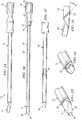
- FIGURE 1Aillustrates an example introducer 10 for implanting a paddle style electrical stimulation lead percutaneously.
- Introducer 10may be used to percutaneously introduce a percutaneous or paddle style lead into the epidural space of a user who requires electrical stimulation treatment directed to spinal nerve tissue, for example, for pain management.
- paddle style leadsgenerally have a width about two times the height of the face of the paddle.
- introducer 10may be used to implant a percutaneous or paddle style lead into other tissue for electrostimulation treatment of a peripheral nerve.
- introducer 10includes an outer sheath 12 and an inner penetrator 14.
- FIGURE 1Billustrates an example inner penetrator 14 disassembled from outer sheath 12.
- Inner penetrator 14includes handle 16, connector 17, and body 18 having proximal end 19 and distal end or tip 20. Tip 20 may be tapered.
- Connector 17connects handle 16 to body 18.
- An inner channel 22is formed through handle 16 and body 18 and connects opening 26 of handle 16 to opening 21 of tip 20.
- Inner channel 22may be configured to attach to a syringe.
- Inner channel 22is wide enough to accommodate guide wires of various sizes along which introducer 10 may be advanced during use.
- Channel 22may taper or otherwise decrease in diameter as it traverses connector 17 at the handle-body junction.
- Inner penetrator 14may be formed from a plastic, such as silastic or another polymer, or any other suitable material. Tip 20 of inner penetrator 14 is curved into a suitable configuration to allow passage around an anatomical obstruction .
- FIGURE 1Cillustrates outer sheath 12 disassembled from inner penetrator 14.
- the lumen of outer sheath 12may range in width, for example from approximately 2mm to approximately 6mm.
- the lumenmay be oblong, oval, or substantially rectangular as needed to accommodate paddle style leads of various configurations.
- Outer sheath 12may taper slightly at tip 29. Tip 29 of outer sheath 12 may be beveled to allow easier passage through tissue and to allow inner penetrator 14 to protrude out of tip 29.
- Outer sheath 12is preferably formed from a metal, such as stainless steel or titanium, or any other suitable material that is stiff and resists bending when outer sheath 12 is inserted through the paravertebral tissue and into the epidural space.
- inner penetrator 14includes tapered tip 20 shown in FIGURE 1D . Tapered tip 20 protrudes out of outer sheath 12. Tapered tip 20 preferably allows introducer 10 to pass easily over a guide wire without creating a false passage in an undesirable location in the tissue.
- tip 20includes a raised circumferential shoulder or ridge 23 configured to provide an indication or "feel” to a physician as raised ridge 23 comes in contact with the ligamentum flavum.
- This "feel”occurs when raised ridge 23 comes in contact with the ligamentum flavum causing a slight resistance, pressure, or “notch” feel to the physician as raised ridge 23 comes in contact with and passes through the ligamentum flavum.
- this aspectmay provide an important indication to the physician as to the location of outer sheath 12 and thus introducer 10 as a whole.
- Such a raised ridge 23can also be applied to needles or cutting devices that otherwise fail to provide physicians sufficient "feel” or a locative indication as the needle cuts through the ligamentum flavum.
- the edge of outer sheath 12 in FIGURE 1Ecould be configured into a cutting surface for a paddle insertion type needle.
- the improvement of raised ridge 23 on such a cutting devicewould provide the needed "feel" or indication to the physician as to where the needle was in the human tissue, thus providing confidence to the physician, as the physician uses such a large needle, that the needle has not yet entered the interthecal space.
- raised ridge 23assists in spreading the fibers of the paravertebral muscle and ligaments as it is inserted.
- Raised ridge 23may be angled to assist insertion, for example, at an angle of thirty-five to forty-five degrees or any other angle that would facilitate passage of outer sheath through tissue.
- raised ridge 23ultimately makes contact with the ligamentum flavum and rests against it during insertion of a guide wire and an electrical stimulation lead.
- outer sheath 12, inner penetrator 14, or bothmay be formed from radio-opaque material or may include radio-opaque markers that allow the position of outer sheath 12, inner penetrator 14, or both to be visualized with fluoroscopy or plain x-rays, for example, during the insertion process to insure proper positioning in the epidural space.
- FIGURES 2A-Fillustrate an example method of implanting a paddle style electrical stimulation lead into a human's epidural space using an example introducer 10.
- Spinal cord 47is also shown.
- a location between two vertebraeis selected for the procedure.
- the sitemay be selected using fluoroscopy.
- the first step in performing the procedureis to insert needle 41, preferably at an angle, into the skin, and through the subcutaneous tissue and ligamentum flavum 44 of the spine, and into a human's epidural space 40.
- the introducermight be inserted at an angle of approximately thirty-five to approximately forty-five degrees.
- FIGURE 2Aillustrates insertion of needle 41 through the skin between spinous processes 42 of two vertebrae 43. Entry into epidural space 40 by needle 41 may be confirmed using standard methods such as the "loss-of-resistance" technique after stylet 45, or inner portion of needle 41, is removed.
- guide wire 46may be inserted through needle 41 into epidural space 40, shown in FIGURE 2B .
- a guide wireis used in a preferred embodiment of the method of insertion but is not required to insert a paddle style lead through the introducer. This part of the procedure may be performed under fluoroscopic guidance for example. Fluoroscopy may be used to check the position of guide wire 46 in epidural space 40 before inserting introducer 10. Once the tip of guide wire 46 is within epidural space 40, needle 41 is removed.
- introducer 10may then be inserted, preferably at an angle of approximately thirty-five to approximately forty-five degrees, although the exact angle may differ depending on technique and a patient's anatomy, over guide wire 46 and into epidural space 40 using guide wire 46 as a guide.
- the technique of passing introducer 10 over guide wire 46helps ensure proper placement of introducer 10 into epidural space 40 and helps avoid inadvertent passage of introducer 10 into an unsuitable location.
- the operatormay choose to cut the skin around the insertion site with a scalpel to facilitate subsequent entry of introducer 10 through the needle entry site.
- introducer 10As introducer 10 is passed through the skin it elongates the hole in the skin made by needle 41. As introducer 10 is passed deeper into the paravertebral tissues, it spreads the fibers of tissue, muscle and ligamentum flavum 44 and forms a tract through these tissues and into epidural space 40, preferably without cutting the tissues. At the level in the tissues where introducer 10 meets and penetrates ligamentum flavum 44 there is a second loss of resistance when inner penetrator 14 has completely penetrated the ligamentum flavum 44. Shoulder or ridge 23 of outer sheath 12 is preferably lodged against ligamentum flavum 44 during insertion of a paddle style lead.
- inner penetrator 14 and guide wire 46may be removed, leaving outer sheath 12 positioned in epidural space 40, as shown in FIGURE 2D .
- paddle style lead 50may then be inserted through outer sheath 12 and positioned at an optimal vertebral level, using fluoroscopy for example, for the desired therapeutic effect.
- outer sheath 12may then be removed leaving only paddle style lead 50 in epidural space 40, where paddle style lead 50 can be further manipulated if necessary to achieve a desired therapeutic effect.
- Paddle style lead 50may be secured by suturing it to a spinous process.
- introducer 10may be used to implant paddle style lead 50 into epidural space 40 for spinal nerve stimulation.
- the same or an analogous, perhaps smaller, introducer 10may be used to implant an analogous paddle style lead 50 into any appropriate region of the body for peripheral nerve stimulation.
- a paddle style lead 50may have an outer sheath 12 and lumen 28 with a width of approximately 1mm to approximately 3mm.
- a similar method of insertionmay be used to implant a paddle style electrical stimulation lead into a human's peripheral nerve tissue.
- a site for insertion in tissue near a nerveis selected.
- the first step in performing the procedureis to insert a needle into the skin and through the subcutaneous tissue and into tissue near a peripheral nerve. If the needle has a stylet, it may be removed and a guide wire may be inserted through the needle and into the tissue near a peripheral nerve. A guide wire may not be required. Fluoroscopy may or may not be used to guide insertion of a guide wire into tissue near a peripheral nerve.
- introducer 10may be inserted, preferably at an angle that would depend on the anatomy of the body near the peripheral nerve to be stimulated. As introducer 10 is passed through tissues, it elongates the tract made by a needle or guide wire and spreads the tissue. After positioning introducer 10 in tissue adjacent to the peripheral nerve to be stimulated, inner penetrator 14 is removed. A paddle style lead may then be inserted through outer sheath 12. Outer sheath 12 may then be removed leaving only the paddle style lead in position near the peripheral nerve to be stimulated.
- FIGURES 3A and 3Bthere are shown two embodiments of a stimulation system 200, 300.
- the stimulation systemsgenerate and apply a stimulus to a tissue or to a certain location of a body.
- the system 200, 300includes a stimulation or energy source 210, 310 and a lead 50 for application of the stimulus.
- the lead 110 shown in FIGURES 3A and 3Bis the paddle style lead 50.
- the stimulation system 200includes the lead 50 that is coupled to the stimulation source 210.
- the stimulation source 210includes an implantable pulse generator (IPG).
- IPGimplantable pulse generator
- an implantable pulse generator (IPG)is implanted within the body (not shown) that is to receive electrical stimulation from the stimulation source 210.
- An example IPGmay be one manufactured by Advanced Neuromodulation Systems, Inc., such as the Genesis® System, part numbers 3604, 3608, 3609, and 3644.
- the stimulation system 300includes the lead 50 that is coupled to the stimulation source 310.
- the stimulation source 310includes a wireless receiver.
- the stimulation source 310comprising a wireless receiver is implanted within the body (not shown) that is to receive electrical stimulation from the stimulation source 310.
- An example wireless receiver 310may be those wireless receivers manufactured by Advanced Neuromodulation Systems, Inc., such as the Renew® System, part numbers 3408 and 3416.
- the wireless receiver (not shown) within stimulation source 310is capable of receiving wireless signals from a wireless transmitter 320.
- the wireless signalsare represented in FIGURE 3B by wireless link symbol 330.
- the wireless transmitter 320 and a controller 340are located outside of the body that is to receive electrical stimulation from the stimulation source 310.
- a user of the stimulation source 310may use the controller 340 to provide control signals for the operation of the stimulation source 310.
- the controller 340provides control signals to the wireless transmitter 320.
- the wireless transmitter 320transmits the control signals (and power) to the receiver in the stimulation source 310 and the stimulation source 310 uses the control signals to vary the signal parameters of the electrical signals that are transmitted through lead 110 to the stimulation site.
- An example wireless transmitter 320may be those transmitters manufactured by Advanced Neuromodulation Systems, Inc., such as the Renew® System, part numbers 3508 and 3516.
- the connectorsare not visible in FIGURES 3A and 3B because the contact electrodes are situated within a receptacle (not shown) of the stimulation source 210, 310.
- the connectorsare in electrical contact with a generator (not shown) of electrical signals within the stimulation source 210, 310.
- the stimulation source 210, 310generates and sends electrical signals via the lead 50 to the electrodes 160.
- the electrodes 160are located at a stimulation site (not shown) within the body that is to receive electrical stimulation from the electrical signals.
- a stimulation sitemay be, for example, adjacent to one or more nerves in the central nervous system (e.g., spinal cord) or peripheral nerves.
- the stimulation source 210, 310is capable of controlling the electrical signals by varying signal parameters (e.g., intensity, duration, frequency) in response to control signals that are provided to the stimulation source 210, 310.
- Lead 110extends from the insertion site to the implant site (the area of placement of the generator).
- the implant siteis typically a subcutaneous pocket that receives and houses the IPG or receiver (providing stimulation source 210, 310).
- the implant siteis usually positioned a distance away from the stimulation site, such as near the buttocks or other place in the torso area. In most cases, the implant site (and insertion site) is located in the lower back area, and lead 110 may extend through the epidural space (or other space) in the spine to the stimulation site (e.g., middle or upper back, neck, or brain areas).
- the system of leads and/or extensionsmay be subject to mechanical forces and movement in response to body movement.
- FIGURE 4illustrates the steps that may be used to implant a stimulation system 200, 300 into a human.
Landscapes
- Health & Medical Sciences (AREA)
- Life Sciences & Earth Sciences (AREA)
- Surgery (AREA)
- Heart & Thoracic Surgery (AREA)
- General Health & Medical Sciences (AREA)
- Veterinary Medicine (AREA)
- Engineering & Computer Science (AREA)
- Biomedical Technology (AREA)
- Nuclear Medicine, Radiotherapy & Molecular Imaging (AREA)
- Public Health (AREA)
- Animal Behavior & Ethology (AREA)
- Pathology (AREA)
- Medical Informatics (AREA)
- Molecular Biology (AREA)
- Neurosurgery (AREA)
- Cardiology (AREA)
- Radiology & Medical Imaging (AREA)
- Orthopedic Medicine & Surgery (AREA)
- Gastroenterology & Hepatology (AREA)
- Neurology (AREA)
- Electrotherapy Devices (AREA)
Abstract
Description
- This invention relates generally to electrical stimulation leads for medical applications and in particular to an apparatus for implanting an electrical stimulation system that includes a paddle style electrical stimulation lead.
- Electrical energy is applied to the spinal cord and peripheral nerves to treat regions of the body that are affected by chronic pain from a variety of etiologies. One method of delivering electrical energy is to implant an electrode and position it in a precise location adjacent the spinal cord such that stimulation of the electrode causes a subjective sensation of numbness or tingling in the affected region of the body, known as "paresthesia." Pain managing electrical energy is commonly delivered through electrodes positioned external to the dura layer surrounding the spinal cord. The electrodes may be carried by either of two primary vehicles: a percutaneous lead and a laminotomy or "paddle" lead.
- Percutaneous leads commonly have three or more equally-spaced electrodes. They are positioned above the dura layer using a needle that is passed through the skin, between the desired vertebrae and onto the top of the dura. Percutaneous leads deliver energy radially in all directions because of the circumferential nature of the electrode. Percutaneous leads can be implanted using a minimally invasive technique. In a typical percutaneous lead placement, a trial stimulation procedure is performed to determine the optimal location for the lead. Here, a needle is placed through the skin and between the desired vertebrae. The percutaneous lead is then threaded through the needle into the desired location over the spinal cord dura. Percutaneous leads may also be positioned in other regions of the body near peripheral nerves for the same purpose.
- Laminotomy or paddle style leads have a paddle-like configuration and typically possess multiple electrodes arranged in one or more independent columns. Paddle style leads provide a more focused energy delivery than percutaneous leads because electrodes may be present on only one surface of the lead. Paddle style leads may be desirable in certain situations because they provide more direct stimulation to a specific surface and require less energy to produce a desired effect. Because paddle style leads are larger than percutaneous leads, they have historically required surgical implantation through a procedure known as partial laminectomy that requires the resection and removal of vertebral tissue.
- The invention is defined in
claims 1 and 19 DocumentUS-A-2002/147485 discloses the most relevant prior art. - To provide a more complete understanding of the present invention and the features and advantages thereof, reference is made to the following description taken in conjunction with the accompanying drawings, in which:
FIGURE 1A illustrates an example introducer for implanting a paddle style electrical stimulation lead;FIGURE 1B illustrates an example inner penetrator of an introducer for implanting a paddle style electrical stimulation lead;FIGURE 1C illustrates an example of an outer sheath of an introducer for implanting a paddle style electrical stimulation lead;FIGURE 1D illustrates an example of a tip of an introducer for implanting a paddle style electrical stimulation lead;FIGURE 1E illustrates an example of a tip of an outer sheath of an introducer for implanting a paddle style electrical stimulation lead;FIGURE 1F illustrates a side view of an example of a tip of an introducer for implanting a paddle style electrical stimulation lead;FIGURE 2A illustrates an example of a needle inserted into a human's epidural space;FIGURE 2B illustrates an example of a guide wire being inserted through a needle into a human's epidural space;FIGURE 2C illustrates an example of an introducer being inserted over a guide wire into a human's epidural space;FIGURE 2D illustrates an example of an inner penetrator being removed from the outer sheath of an introducer in a human's epidural space;FIGURE 2E illustrates an example of a paddle style lead being inserted through an introducer into a human's epidural space;FIGURE 2F illustrates an example of a paddle style lead implanted in a human's epidural space;FIGURE 3A illustrates an example of a stimulation system;FIGURE 3B illustrates an example of a stimulation system; andFIGURE 4 is a flow chart describing steps for implanting a stimulation system.FIGURE 1A illustrates an example introducer 10 for implanting a paddle style electrical stimulation lead percutaneously. Introducer 10 may be used to percutaneously introduce a percutaneous or paddle style lead into the epidural space of a user who requires electrical stimulation treatment directed to spinal nerve tissue, for example, for pain management. As known in the art, paddle style leads generally have a width about two times the height of the face of the paddle. The same or an analogous, perhaps smaller, introducer 10 may be used to implant a percutaneous or paddle style lead into other tissue for electrostimulation treatment of a peripheral nerve. In one embodiment,introducer 10 includes anouter sheath 12 and aninner penetrator 14.FIGURE 1B illustrates an exampleinner penetrator 14 disassembled fromouter sheath 12.Inner penetrator 14 includeshandle 16,connector 17, andbody 18 havingproximal end 19 and distal end ortip 20.Tip 20 may be tapered.Connector 17 connectshandle 16 tobody 18. Aninner channel 22 is formed throughhandle 16 andbody 18 and connects opening 26 ofhandle 16 to opening 21 oftip 20.Inner channel 22 may be configured to attach to a syringe.Inner channel 22 is wide enough to accommodate guide wires of various sizes along which introducer 10 may be advanced during use.Channel 22 may taper or otherwise decrease in diameter as it traversesconnector 17 at the handle-body junction.Inner penetrator 14 may be formed from a plastic, such as silastic or another polymer, or any other suitable material.Tip 20 ofinner penetrator 14 is curved into a suitable configuration to allow passage around an anatomical obstruction .FIGURE 1C illustratesouter sheath 12 disassembled frominner penetrator 14. The lumen ofouter sheath 12 may range in width, for example from approximately 2mm to approximately 6mm. The lumen may be oblong, oval, or substantially rectangular as needed to accommodate paddle style leads of various configurations.Outer sheath 12 may taper slightly attip 29.Tip 29 ofouter sheath 12 may be beveled to allow easier passage through tissue and to allowinner penetrator 14 to protrude out oftip 29.Outer sheath 12 is preferably formed from a metal, such as stainless steel or titanium, or any other suitable material that is stiff and resists bending whenouter sheath 12 is inserted through the paravertebral tissue and into the epidural space. In one embodiment,inner penetrator 14 includestapered tip 20 shown inFIGURE 1D . Taperedtip 20 protrudes out ofouter sheath 12. Taperedtip 20 preferably allows introducer 10 to pass easily over a guide wire without creating a false passage in an undesirable location in the tissue.- In one embodiment of
outer sheath 12, shown inFIGURES 1D-F ,tip 20 includes a raised circumferential shoulder orridge 23 configured to provide an indication or "feel" to a physician as raisedridge 23 comes in contact with the ligamentum flavum. This "feel" occurs when raisedridge 23 comes in contact with the ligamentum flavum causing a slight resistance, pressure, or "notch" feel to the physician as raisedridge 23 comes in contact with and passes through the ligamentum flavum. As many physicians rely on "feel" while performing delicate procedures, this aspect may provide an important indication to the physician as to the location ofouter sheath 12 and thus introducer 10 as a whole. - Such a raised
ridge 23 can also be applied to needles or cutting devices that otherwise fail to provide physicians sufficient "feel" or a locative indication as the needle cuts through the ligamentum flavum. For example, the edge ofouter sheath 12 inFIGURE 1E could be configured into a cutting surface for a paddle insertion type needle. The improvement of raisedridge 23 on such a cutting device would provide the needed "feel" or indication to the physician as to where the needle was in the human tissue, thus providing confidence to the physician, as the physician uses such a large needle, that the needle has not yet entered the interthecal space. - Further, raised
ridge 23 assists in spreading the fibers of the paravertebral muscle and ligaments as it is inserted. Raisedridge 23 may be angled to assist insertion, for example, at an angle of thirty-five to forty-five degrees or any other angle that would facilitate passage of outer sheath through tissue. During insertion, raisedridge 23 ultimately makes contact with the ligamentum flavum and rests against it during insertion of a guide wire and an electrical stimulation lead. - In one embodiment,
outer sheath 12,inner penetrator 14, or both may be formed from radio-opaque material or may include radio-opaque markers that allow the position ofouter sheath 12,inner penetrator 14, or both to be visualized with fluoroscopy or plain x-rays, for example, during the insertion process to insure proper positioning in the epidural space. FIGURES 2A-F illustrate an example method of implanting a paddle style electrical stimulation lead into a human's epidural space using anexample introducer 10.Spinal cord 47 is also shown. A location between two vertebrae is selected for the procedure. The site may be selected using fluoroscopy. The first step in performing the procedure is to insertneedle 41, preferably at an angle, into the skin, and through the subcutaneous tissue and ligamentum flavum 44 of the spine, and into a human'sepidural space 40. In one embodiment of the method, for example, the introducer might be inserted at an angle of approximately thirty-five to approximately forty-five degrees.FIGURE 2A illustrates insertion ofneedle 41 through the skin betweenspinous processes 42 of twovertebrae 43. Entry intoepidural space 40 byneedle 41 may be confirmed using standard methods such as the "loss-of-resistance" technique afterstylet 45, or inner portion ofneedle 41, is removed.- After removing
stylet 45 fromneedle 41,guide wire 46 may be inserted throughneedle 41 intoepidural space 40, shown inFIGURE 2B . A guide wire is used in a preferred embodiment of the method of insertion but is not required to insert a paddle style lead through the introducer. This part of the procedure may be performed under fluoroscopic guidance for example. Fluoroscopy may be used to check the position ofguide wire 46 inepidural space 40 before insertingintroducer 10. Once the tip ofguide wire 46 is withinepidural space 40,needle 41 is removed. As shown inFIGURE 2C ,introducer 10 may then be inserted, preferably at an angle of approximately thirty-five to approximately forty-five degrees, although the exact angle may differ depending on technique and a patient's anatomy, overguide wire 46 and intoepidural space 40 usingguide wire 46 as a guide. The technique of passingintroducer 10 overguide wire 46 helps ensure proper placement ofintroducer 10 intoepidural space 40 and helps avoid inadvertent passage ofintroducer 10 into an unsuitable location. The operator may choose to cut the skin around the insertion site with a scalpel to facilitate subsequent entry ofintroducer 10 through the needle entry site. - As
introducer 10 is passed through the skin it elongates the hole in the skin made byneedle 41. Asintroducer 10 is passed deeper into the paravertebral tissues, it spreads the fibers of tissue, muscle and ligamentum flavum 44 and forms a tract through these tissues and intoepidural space 40, preferably without cutting the tissues. At the level in the tissues whereintroducer 10 meets and penetrates ligamentum flavum 44 there is a second loss of resistance wheninner penetrator 14 has completely penetrated theligamentum flavum 44. Shoulder orridge 23 ofouter sheath 12 is preferably lodged against ligamentum flavum 44 during insertion of a paddle style lead. - Once
introducer 10 has completely penetrated ligamentum flavum,inner penetrator 14 andguide wire 46 may be removed, leavingouter sheath 12 positioned inepidural space 40, as shown inFIGURE 2D . As shown inFIGURE 2E ,paddle style lead 50 may then be inserted throughouter sheath 12 and positioned at an optimal vertebral level, using fluoroscopy for example, for the desired therapeutic effect. As shown inFIGURE 2F ,outer sheath 12 may then be removed leaving onlypaddle style lead 50 inepidural space 40, wherepaddle style lead 50 can be further manipulated if necessary to achieve a desired therapeutic effect.Paddle style lead 50 may be secured by suturing it to a spinous process. - As described above,
introducer 10 may be used to implantpaddle style lead 50 intoepidural space 40 for spinal nerve stimulation. The same or an analogous, perhaps smaller,introducer 10 may be used to implant an analogouspaddle style lead 50 into any appropriate region of the body for peripheral nerve stimulation. For example, such apaddle style lead 50 may have anouter sheath 12 andlumen 28 with a width of approximately 1mm to approximately 3mm. - A similar method of insertion (not expressly shown) may be used to implant a paddle style electrical stimulation lead into a human's peripheral nerve tissue. In this embodiment a site for insertion in tissue near a nerve is selected. The first step in performing the procedure is to insert a needle into the skin and through the subcutaneous tissue and into tissue near a peripheral nerve. If the needle has a stylet, it may be removed and a guide wire may be inserted through the needle and into the tissue near a peripheral nerve. A guide wire may not be required. Fluoroscopy may or may not be used to guide insertion of a guide wire into tissue near a peripheral nerve. Once the tip of the guide wire, or needle, is in the tissue near a peripheral nerve,
introducer 10 may be inserted, preferably at an angle that would depend on the anatomy of the body near the peripheral nerve to be stimulated. Asintroducer 10 is passed through tissues, it elongates the tract made by a needle or guide wire and spreads the tissue. After positioningintroducer 10 in tissue adjacent to the peripheral nerve to be stimulated,inner penetrator 14 is removed. A paddle style lead may then be inserted throughouter sheath 12.Outer sheath 12 may then be removed leaving only the paddle style lead in position near the peripheral nerve to be stimulated. - Now referring to
FIGURES 3A and 3B , there are shown two embodiments of astimulation system system energy source lead 50 for application of the stimulus. Thelead 110 shown inFIGURES 3A and 3B is thepaddle style lead 50. - As shown in
FIGURE 3A , thestimulation system 200 includes thelead 50 that is coupled to thestimulation source 210. In one embodiment, thestimulation source 210 includes an implantable pulse generator (IPG). As is known in the art, an implantable pulse generator (IPG) is implanted within the body (not shown) that is to receive electrical stimulation from thestimulation source 210. An example IPG may be one manufactured by Advanced Neuromodulation Systems, Inc., such as the Genesis® System, part numbers 3604, 3608, 3609, and 3644. - As shown in
FIGURE 3B , thestimulation system 300 includes thelead 50 that is coupled to thestimulation source 310. Thestimulation source 310 includes a wireless receiver. As is known in the art, thestimulation source 310 comprising a wireless receiver is implanted within the body (not shown) that is to receive electrical stimulation from thestimulation source 310. Anexample wireless receiver 310 may be those wireless receivers manufactured by Advanced Neuromodulation Systems, Inc., such as the Renew® System, part numbers 3408 and 3416. - The wireless receiver (not shown) within
stimulation source 310 is capable of receiving wireless signals from awireless transmitter 320. The wireless signals are represented inFIGURE 3B bywireless link symbol 330. Thewireless transmitter 320 and acontroller 340 are located outside of the body that is to receive electrical stimulation from thestimulation source 310. A user of thestimulation source 310 may use thecontroller 340 to provide control signals for the operation of thestimulation source 310. Thecontroller 340 provides control signals to thewireless transmitter 320. Thewireless transmitter 320 transmits the control signals (and power) to the receiver in thestimulation source 310 and thestimulation source 310 uses the control signals to vary the signal parameters of the electrical signals that are transmitted throughlead 110 to the stimulation site. Anexample wireless transmitter 320 may be those transmitters manufactured by Advanced Neuromodulation Systems, Inc., such as the Renew® System, part numbers 3508 and 3516. - As will be appreciated, the connectors are not visible in
FIGURES 3A and 3B because the contact electrodes are situated within a receptacle (not shown) of thestimulation source stimulation source stimulation source lead 50 to theelectrodes 160. Understandably, theelectrodes 160 are located at a stimulation site (not shown) within the body that is to receive electrical stimulation from the electrical signals. A stimulation site may be, for example, adjacent to one or more nerves in the central nervous system (e.g., spinal cord) or peripheral nerves. Thestimulation source stimulation source - As described above, once
lead 110 is inserted into either the epidural space or near the peripheral nerve,introducer 10 is removed.Lead 110 extends from the insertion site to the implant site (the area of placement of the generator). The implant site is typically a subcutaneous pocket that receives and houses the IPG or receiver (providingstimulation source 210, 310). The implant site is usually positioned a distance away from the stimulation site, such as near the buttocks or other place in the torso area. In most cases, the implant site (and insertion site) is located in the lower back area, and lead 110 may extend through the epidural space (or other space) in the spine to the stimulation site (e.g., middle or upper back, neck, or brain areas). Once the system is implanted, the system of leads and/or extensions may be subject to mechanical forces and movement in response to body movement.FIGURE 4 illustrates the steps that may be used to implant astimulation system - Although the present invention has been described with several embodiments, a number of changes, substitutions, variations, alterations, and modifications may be suggested to one skilled in the art, and it is intended that the invention encompass all such changes, substitutions, variations, alterations, and modifications as fall within the scope of the appended claims.
Claims (19)
- An introducer for implanting an electrical stimulation lead to enable electrical stimulation of nerve tissue, comprising:an outer sheath configured to accommodate insertion of the electrical stimulation lead through the outer sheath, the outer sheath operable to be inserted into a human body near the nerve tissue; andan inner penetrator removably housed within the outer sheath and comprising an inner channel configured to accommodate a guide wire, the inner penetrator configured to be advanced along the guide wire to a desired location relative to the nerve tissue and removed from the outer sheath leaving the outer sheath substantially in position for insertion of the electrical stimulation lead through the outer sheath into position proximate the nerve tissue,characterized in that the tip of the inner penetrator and the tip of the outer sheath comprise a curved portion to allow passage of the inner penetrator and outer sheath around an anatomical obstruction.
- The introducer of Claim 1, wherein the lead is greater than 1.5 millimeters in width.
- The introducer of Claim 1, wherein the electrical stimulation lead has a width of at least approximately two times its height.
- The introducer of Claim 1, wherein the electrical stimulation lead is a paddle style lead.
- The introducer of Claim 1, wherein the nerve tissue comprises spinal nerve tissue and the desired location comprises an epidural space of the human.
- The introducer of Claim 1, wherein the nerve tissue comprises a peripheral nerve.
- The introducer of Claim 1, wherein the inner penetrator comprises a hollow tip configured to extend beyond the outer sheath.
- The introducer of Claim 1, wherein the outer sheath has a raised circumferential ridge configured to create resistance when the circumferential ridge contacts the human's ligamentum flavum.
- The introducer of Claim 1, wherein the inner penetrator and outer sheath comprise one or more radio-opaque markers for visualization using fluoroscopy.
- The introducer of Claim 1, wherein the outer sheath has a substantially oval cross-section.
- The introducer of Claim 1, wherein the outer sheath has a substantially oblong cross-section.
- The introducer of Claim 1, wherein the outer sheath is formed of metal comprising titanium or stainless steel.
- The introducer of Claim 1, wherein the inner penetrator is formed from one or more of plastic, silastic, or a polymeric material.
- The introducer of Claim 1, wherein the tip of the outer penetrator is tapered.
- The introducer of Claim 1, wherein the inner penetrator is configured to be advanced until an end of the inner penetrator is positioned in the human's epidural space at a desired location relative to the nerve tissue such that the outer sheath forms an insertion tract for the electrical stimulation lead as the inner penetrator advances along the guide wire.
- The introducer of Claim 1, wherein the tip of the introducer is tapered and hollow.
- The introducer of Claim 1, wherein the outer sheath comprises a circumferential ridge configured to create resistance when the circumferential ridge contacts a ligamentum flavum of a human.
- The introducer of Claim 1, wherein the needle comprises a removable stylet configured to be removed before inserting the guide wire.
- A system for implanting an electrical stimulation lead to enable electrical stimulation of a human's spinal nerve tissue, comprising:a needle;a guide wire;an introducer comprising an outer sheath and an inner penetrator;the outer sheath configured to accommodate insertion of the electrical stimulation lead through the outer sheath, the outer sheath operable to be inserted through the human's skin and into the human's epidural space;an inner penetrator removably housed within the outer sheath and comprising an inner channel configured to accommodate a guide wire;the inner penetrator configured to be advanced along the guide wire until an end of the inner penetrator is positioned in the epidural space at a desired location relative to spinal nerve tissue to be stimulated such that the outer sheath forms an insertion tract for the electrical stimulation lead as the inner penetrator advances along the guide wire, the inner penetrator configured to be removed from the outer sheath leaving the outer sheath substantially in position in the epidural space for insertion of the electrical stimulation lead through the outer sheath into position proximate the spinal nerve tissue to be stimulated; and an implantable generator to power the electrical stimulation lead,
characterized in that the tip of the inner penetrator and the tip of the outer sheath comprise a curved portion to allow passage of the inner penetrator and outer sheath around an anatomical obstruction.
Priority Applications (1)
| Application Number | Priority Date | Filing Date | Title |
|---|---|---|---|
| EP12157400.8AEP2468355B1 (en) | 2003-08-08 | 2004-07-28 | Apparatus for implanting an electrical stimulation system and a paddle style electrical stimulation lead |
Applications Claiming Priority (2)
| Application Number | Priority Date | Filing Date | Title |
|---|---|---|---|
| US10/637,342US20050033393A1 (en) | 2003-08-08 | 2003-08-08 | Apparatus and method for implanting an electrical stimulation system and a paddle style electrical stimulation lead |
| PCT/US2004/024552WO2005016447A2 (en) | 2003-08-08 | 2004-07-28 | Apparatus and method for implanting an electrical stimulation system and a paddle style electrical stimulation lead |
Related Child Applications (2)
| Application Number | Title | Priority Date | Filing Date |
|---|---|---|---|
| EP12157400.8ADivisionEP2468355B1 (en) | 2003-08-08 | 2004-07-28 | Apparatus for implanting an electrical stimulation system and a paddle style electrical stimulation lead |
| EP12157400.8Division-Into | 2012-02-28 |
Publications (2)
| Publication Number | Publication Date |
|---|---|
| EP1656180A2 EP1656180A2 (en) | 2006-05-17 |
| EP1656180B1true EP1656180B1 (en) | 2012-04-18 |
Family
ID=34116596
Family Applications (2)
| Application Number | Title | Priority Date | Filing Date |
|---|---|---|---|
| EP12157400.8AExpired - LifetimeEP2468355B1 (en) | 2003-08-08 | 2004-07-28 | Apparatus for implanting an electrical stimulation system and a paddle style electrical stimulation lead |
| EP04779566AExpired - LifetimeEP1656180B1 (en) | 2003-08-08 | 2004-07-28 | Apparatus for implanting an electrical stimulation system and a paddle style electrical stimulation lead |
Family Applications Before (1)
| Application Number | Title | Priority Date | Filing Date |
|---|---|---|---|
| EP12157400.8AExpired - LifetimeEP2468355B1 (en) | 2003-08-08 | 2004-07-28 | Apparatus for implanting an electrical stimulation system and a paddle style electrical stimulation lead |
Country Status (4)
| Country | Link |
|---|---|
| US (1) | US20050033393A1 (en) |
| EP (2) | EP2468355B1 (en) |
| AT (1) | ATE553811T1 (en) |
| WO (1) | WO2005016447A2 (en) |
Families Citing this family (100)
| Publication number | Priority date | Publication date | Assignee | Title |
|---|---|---|---|---|
| US7359755B2 (en) | 2003-08-08 | 2008-04-15 | Advanced Neuromodulation Systems, Inc. | Method and apparatus for implanting an electrical stimulation lead using a flexible introducer |
| US20050288758A1 (en)* | 2003-08-08 | 2005-12-29 | Jones Timothy S | Methods and apparatuses for implanting and removing an electrical stimulation lead |
| US8340779B2 (en) | 2003-08-29 | 2012-12-25 | Medtronic, Inc. | Percutaneous flat lead introducer |
| US7392093B2 (en)* | 2003-09-26 | 2008-06-24 | Advanced Neuromodulation Systems, Inc. | Electrical stimulation system including a device for partially shielding electrical energy emitted from one or more electrical stimulation leads implanted in a human's body |
| US20050090801A1 (en)* | 2003-10-27 | 2005-04-28 | Racz N. S. | Safety spinal catheter |
| NL1025830C2 (en)* | 2004-03-26 | 2005-02-22 | Eric Berreklouw | Prosthesis e.g. heart valve secured in place by ring with shape memory material anchor, includes anchor temperature control system |
| US9205261B2 (en) | 2004-09-08 | 2015-12-08 | The Board Of Trustees Of The Leland Stanford Junior University | Neurostimulation methods and systems |
| US7337005B2 (en)* | 2004-09-08 | 2008-02-26 | Spinal Modulations, Inc. | Methods for stimulating a nerve root ganglion |
| US20120277839A1 (en) | 2004-09-08 | 2012-11-01 | Kramer Jeffery M | Selective stimulation to modulate the sympathetic nervous system |
| US20100331883A1 (en) | 2004-10-15 | 2010-12-30 | Schmitz Gregory P | Access and tissue modification systems and methods |
| US7738969B2 (en) | 2004-10-15 | 2010-06-15 | Baxano, Inc. | Devices and methods for selective surgical removal of tissue |
| US20110190772A1 (en) | 2004-10-15 | 2011-08-04 | Vahid Saadat | Powered tissue modification devices and methods |
| US8430881B2 (en)* | 2004-10-15 | 2013-04-30 | Baxano, Inc. | Mechanical tissue modification devices and methods |
| US9247952B2 (en) | 2004-10-15 | 2016-02-02 | Amendia, Inc. | Devices and methods for tissue access |
| US8613745B2 (en)* | 2004-10-15 | 2013-12-24 | Baxano Surgical, Inc. | Methods, systems and devices for carpal tunnel release |
| US7857813B2 (en) | 2006-08-29 | 2010-12-28 | Baxano, Inc. | Tissue access guidewire system and method |
| US7578819B2 (en)* | 2005-05-16 | 2009-08-25 | Baxano, Inc. | Spinal access and neural localization |
| US7959577B2 (en) | 2007-09-06 | 2011-06-14 | Baxano, Inc. | Method, system, and apparatus for neural localization |
| US8062300B2 (en) | 2006-05-04 | 2011-11-22 | Baxano, Inc. | Tissue removal with at least partially flexible devices |
| US8048080B2 (en) | 2004-10-15 | 2011-11-01 | Baxano, Inc. | Flexible tissue rasp |
| US7938830B2 (en)* | 2004-10-15 | 2011-05-10 | Baxano, Inc. | Powered tissue modification devices and methods |
| US8221397B2 (en) | 2004-10-15 | 2012-07-17 | Baxano, Inc. | Devices and methods for tissue modification |
| US7963915B2 (en) | 2004-10-15 | 2011-06-21 | Baxano, Inc. | Devices and methods for tissue access |
| US20090018507A1 (en)* | 2007-07-09 | 2009-01-15 | Baxano, Inc. | Spinal access system and method |
| US20090171381A1 (en)* | 2007-12-28 | 2009-07-02 | Schmitz Gregory P | Devices, methods and systems for neural localization |
| JP5243034B2 (en) | 2004-10-15 | 2013-07-24 | バクサノ,インク. | Tissue removal device |
| US7887538B2 (en)* | 2005-10-15 | 2011-02-15 | Baxano, Inc. | Methods and apparatus for tissue modification |
| US9101386B2 (en) | 2004-10-15 | 2015-08-11 | Amendia, Inc. | Devices and methods for treating tissue |
| US8257356B2 (en) | 2004-10-15 | 2012-09-04 | Baxano, Inc. | Guidewire exchange systems to treat spinal stenosis |
| WO2006135753A1 (en)* | 2005-06-09 | 2006-12-21 | Medtronic, Inc. | Introducer for therapy delivery elements |
| US20080091227A1 (en)* | 2006-08-25 | 2008-04-17 | Baxano, Inc. | Surgical probe and method of making |
| US8092456B2 (en)* | 2005-10-15 | 2012-01-10 | Baxano, Inc. | Multiple pathways for spinal nerve root decompression from a single access point |
| US8366712B2 (en) | 2005-10-15 | 2013-02-05 | Baxano, Inc. | Multiple pathways for spinal nerve root decompression from a single access point |
| US8062298B2 (en)* | 2005-10-15 | 2011-11-22 | Baxano, Inc. | Flexible tissue removal devices and methods |
| US8019442B1 (en) | 2006-10-25 | 2011-09-13 | Advanced Neuromodulation Systems, Inc. | Assembly kit for creating paddle-style lead from one or several percutaneous leads and method of lead implantation |
| US20080132979A1 (en)* | 2006-11-30 | 2008-06-05 | Medtronic, Inc. | Method of implanting a medical lead |
| WO2008070808A2 (en) | 2006-12-06 | 2008-06-12 | Spinal Modulation, Inc. | Expandable stimulation leads and methods of use |
| CA2671250A1 (en) | 2006-12-06 | 2008-06-12 | Spinal Modulation, Inc. | Hard tissue anchors and delivery devices |
| JP5414531B2 (en) | 2006-12-06 | 2014-02-12 | スパイナル・モデュレーション・インコーポレイテッド | Delivery device and systems and methods for stimulating neural tissue at multiple spinal levels |
| US9314618B2 (en) | 2006-12-06 | 2016-04-19 | Spinal Modulation, Inc. | Implantable flexible circuit leads and methods of use |
| CA2671575A1 (en)* | 2006-12-06 | 2008-06-12 | Spinal Modulation, Inc. | Grouped leads for spinal stimulation |
| US20080183188A1 (en)* | 2007-01-25 | 2008-07-31 | Warsaw Orthopedic, Inc. | Integrated Surgical Navigational and Neuromonitoring System |
| US7987001B2 (en)* | 2007-01-25 | 2011-07-26 | Warsaw Orthopedic, Inc. | Surgical navigational and neuromonitoring instrument |
| US20080183068A1 (en)* | 2007-01-25 | 2008-07-31 | Warsaw Orthopedic, Inc. | Integrated Visualization of Surgical Navigational and Neural Monitoring Information |
| US20080183074A1 (en)* | 2007-01-25 | 2008-07-31 | Warsaw Orthopedic, Inc. | Method and apparatus for coordinated display of anatomical and neuromonitoring information |
| US8374673B2 (en)* | 2007-01-25 | 2013-02-12 | Warsaw Orthopedic, Inc. | Integrated surgical navigational and neuromonitoring system having automated surgical assistance and control |
| JP5562648B2 (en) | 2007-01-29 | 2014-07-30 | スパイナル・モデュレーション・インコーポレイテッド | Non-stitched top retaining mechanism |
| WO2008108758A1 (en) | 2007-03-07 | 2008-09-12 | Enpath Medical, Inc. | Self fixing spinal cord stimulation lead and delivery system |
| US9008782B2 (en)* | 2007-10-26 | 2015-04-14 | Medtronic, Inc. | Occipital nerve stimulation |
| JP5004771B2 (en)* | 2007-11-22 | 2012-08-22 | 株式会社リコー | Image forming apparatus |
| US8192436B2 (en)* | 2007-12-07 | 2012-06-05 | Baxano, Inc. | Tissue modification devices |
| NZ586548A (en)* | 2008-01-14 | 2012-07-27 | Custom Med Applications Inc | Flexible spinal needle assembly with an internal flow element configured to avoid kinking or restriction of the needle |
| US8287496B2 (en)* | 2008-01-17 | 2012-10-16 | Custom Medical Applications, Inc. | Flow elements for use with flexible spinal needles, needle assemblies and methods therefor |
| EP2252365B1 (en)* | 2008-02-21 | 2013-10-16 | Boston Scientific Neuromodulation Corporation | Temporary neurostimulation lead identification device |
| USD597667S1 (en)* | 2008-03-20 | 2009-08-04 | Custom Medical Applications, Inc. | Flexible spinal needle |
| US9492655B2 (en)* | 2008-04-25 | 2016-11-15 | Boston Scientific Neuromodulation Corporation | Stimulation system with percutaneously deliverable paddle lead and methods of making and using |
| US8409206B2 (en) | 2008-07-01 | 2013-04-02 | Baxano, Inc. | Tissue modification devices and methods |
| US8398641B2 (en) | 2008-07-01 | 2013-03-19 | Baxano, Inc. | Tissue modification devices and methods |
| US9314253B2 (en) | 2008-07-01 | 2016-04-19 | Amendia, Inc. | Tissue modification devices and methods |
| AU2009271047B2 (en)* | 2008-07-14 | 2014-04-17 | Baxano Surgical, Inc. | Tissue modification devices |
| US20100030227A1 (en)* | 2008-07-31 | 2010-02-04 | Medtronic, Inc. | Medical lead implantation |
| US7941227B2 (en)* | 2008-09-03 | 2011-05-10 | Boston Scientific Neuromodulation Corporation | Implantable electric stimulation system and methods of making and using |
| EP2373378B1 (en)* | 2008-10-27 | 2017-04-26 | Spinal Modulation Inc. | Selective stimulation systems and signal parameters for medical conditions |
| US8874235B1 (en) | 2008-12-12 | 2014-10-28 | Greatbatch Ltd. | Self fixing spinal cord stimulation paddle lead |
| AU2010204703B8 (en)* | 2009-01-14 | 2015-10-08 | Spinal Modulation, Inc. | Stimulation leads, delivery systems and methods of use |
| EP2405823A4 (en) | 2009-03-13 | 2012-07-04 | Baxano Inc | Flexible neural localization devices and methods |
| US8380318B2 (en) | 2009-03-24 | 2013-02-19 | Spinal Modulation, Inc. | Pain management with stimulation subthreshold to paresthesia |
| WO2010132816A2 (en) | 2009-05-15 | 2010-11-18 | Spinal Modulation, Inc. | Methods, systems and devices for neuromodulating spinal anatomy |
| US8394102B2 (en)* | 2009-06-25 | 2013-03-12 | Baxano, Inc. | Surgical tools for treatment of spinal stenosis |
| US8929998B2 (en) | 2009-09-30 | 2015-01-06 | Mayo Foundation For Medical Education And Research | Percutaneous placement of electrodes |
| US11045221B2 (en)* | 2009-10-30 | 2021-06-29 | Medtronic, Inc. | Steerable percutaneous paddle stimulation lead |
| CA2798961A1 (en) | 2010-05-10 | 2011-11-17 | Spinal Modulation, Inc. | Methods, systems and devices for reducing migration |
| CN103561811A (en) | 2011-02-02 | 2014-02-05 | 脊髓调制公司 | Devices, systems and methods for the targeted treatment of movement disorders |
| US8986382B2 (en) | 2011-05-03 | 2015-03-24 | Boston Scientific Neuromodulation Corporation | Tissue fixation and repair systems and methods |
| EP2773423B1 (en) | 2011-11-04 | 2024-01-10 | Nevro Corporation | Medical device communication and charding assemblies for use with implantable signal generators |
| US10751081B2 (en)* | 2012-03-30 | 2020-08-25 | Medtronic, Inc. | Methods and tools for clearing the epidural space in preparation for medical lead implantation |
| US10080896B2 (en) | 2013-03-15 | 2018-09-25 | Cirtec Medical Corp. | Implantable pulse generator that generates spinal cord stimulation signals for a human body |
| US9440076B2 (en) | 2013-03-15 | 2016-09-13 | Globus Medical, Inc. | Spinal cord stimulator system |
| US10226628B2 (en) | 2013-03-15 | 2019-03-12 | Cirtec Medical Corp. | Implantable pulse generator that generates spinal cord stimulation signals for a human body |
| US10413730B2 (en) | 2013-03-15 | 2019-09-17 | Cirtec Medical Corp. | Implantable pulse generator that generates spinal cord stimulation signals for a human body |
| US10016604B2 (en) | 2013-03-15 | 2018-07-10 | Globus Medical, Inc. | Implantable pulse generator that generates spinal cord stimulation signals for a human body |
| WO2014165783A1 (en)* | 2013-04-05 | 2014-10-09 | University Of Iowa Research Foundation | Catheter assembly with segmented stabilization system |
| US9517334B2 (en) | 2013-08-19 | 2016-12-13 | Boston Scientific Neuromodulation Corporation | Lead anchors and systems and methods employing the lead anchors |
| ES2821302T3 (en) | 2015-03-20 | 2021-04-26 | Intelligent Implants Ltd | Dynamic bone growth stimulation system |
| US9636498B2 (en) | 2015-08-03 | 2017-05-02 | Boston Scientific Neuromodulation Corporation | Lead anchor with a wedge and systems using the lead anchor |
| AU2016340161B2 (en)* | 2015-10-15 | 2021-07-15 | Spr Therapeutics, Inc. | Apparatus and method for positioning, implanting and using a stimulation lead |
| US11135437B2 (en) | 2015-10-15 | 2021-10-05 | Spr Therapeutics, Inc. | Apparatus and method for positioning, implanting and using a stimulation lead |
| US10617880B2 (en) | 2015-12-08 | 2020-04-14 | Intelligent Implants Limited | System and method for an electrical implant device with increased patient compliance |
| WO2017151438A1 (en) | 2016-02-29 | 2017-09-08 | Boston Scientific Neuromodulation Corporation | Lead anchor for an electrical stimulation system |
| WO2017201058A1 (en) | 2016-05-17 | 2017-11-23 | Boston Scientific Neuromodulation Corporation | Systems and methods for anchoring a lead for neurostimulation of a target anatomy |
| US10709886B2 (en) | 2017-02-28 | 2020-07-14 | Boston Scientific Neuromodulation Corporation | Electrical stimulation leads and systems with elongate anchoring elements and methods of making and using |
| US10835739B2 (en) | 2017-03-24 | 2020-11-17 | Boston Scientific Neuromodulation Corporation | Electrical stimulation leads and systems with elongate anchoring elements and methods of making and using |
| US10857351B2 (en) | 2017-04-28 | 2020-12-08 | Boston Scientific Neuromodulation Corporation | Lead anchors for electrical stimulation leads and systems and methods of making and using |
| US11166745B2 (en)* | 2017-09-12 | 2021-11-09 | Jessica Jameson | Multi-port epidural needle |
| WO2019213181A1 (en) | 2018-05-01 | 2019-11-07 | Sandhu Prabdeep | A 2.4 ghz radio antenna for implanted medical devices, and associated systems and methods |
| US11576789B2 (en) | 2018-10-03 | 2023-02-14 | Intelligent Implants Limited | System and method to alter bone growth in a targeted spatial region for the use with implants |
| US11633223B2 (en) | 2018-12-20 | 2023-04-25 | Integrity Implants Inc. | Surgical guidance device |
| US11844706B2 (en) | 2019-03-20 | 2023-12-19 | Grabango Co. | System and method for positioning and orienting an orthopedic implant |
| US11944818B2 (en) | 2019-11-01 | 2024-04-02 | Intelligent Implants Limited | System and method for embedding electronic components within an implant |
| WO2024238333A2 (en)* | 2023-05-12 | 2024-11-21 | University Of Pittsburgh - Of The Commonwealth System Of Higher Education | Needle for delivery of multiple extending elements to tissue |
Family Cites Families (19)
| Publication number | Priority date | Publication date | Assignee | Title |
|---|---|---|---|---|
| US4512351A (en)* | 1982-11-19 | 1985-04-23 | Cordis Corporation | Percutaneous lead introducing system and method |
| US4573448A (en)* | 1983-10-05 | 1986-03-04 | Pilling Co. | Method for decompressing herniated intervertebral discs |
| US5478806A (en)* | 1989-11-22 | 1995-12-26 | Enzon, Inc. | Enhancement of antitumor therapy with hemoglobin-based conjugates |
| DE69123982T2 (en)* | 1990-11-20 | 1997-12-04 | Innerdyne Medical Inc | STRETCH MAINTENANCE GUIDE ELEMENT AND DILATATOR |
| US5275504A (en)* | 1991-05-09 | 1994-01-04 | Linear Dynamics, Inc. | Glass bead application sensor system |
| US5255691A (en)* | 1991-11-13 | 1993-10-26 | Medtronic, Inc. | Percutaneous epidural lead introducing system and method |
| US5431676A (en)* | 1993-03-05 | 1995-07-11 | Innerdyne Medical, Inc. | Trocar system having expandable port |
| US5562695A (en)* | 1995-01-10 | 1996-10-08 | Obenchain; Theodore G. | Nerve deflecting conduit needle and method |
| US5792044A (en)* | 1996-03-22 | 1998-08-11 | Danek Medical, Inc. | Devices and methods for percutaneous surgery |
| US6530902B1 (en)* | 1998-01-23 | 2003-03-11 | Medtronic, Inc. | Cannula placement system |
| US6104960A (en)* | 1998-07-13 | 2000-08-15 | Medtronic, Inc. | System and method for providing medical electrical stimulation to a portion of the nervous system |
| US6055456A (en)* | 1999-04-29 | 2000-04-25 | Medtronic, Inc. | Single and multi-polar implantable lead for sacral nerve electrical stimulation |
| US6309401B1 (en)* | 1999-04-30 | 2001-10-30 | Vladimir Redko | Apparatus and method for percutaneous implant of a paddle style lead |
| US6249707B1 (en)* | 1999-04-30 | 2001-06-19 | Medtronic, Inc. | Apparatus and method for percutaneous implant of a paddle style lead |
| US6895283B2 (en)* | 2000-08-10 | 2005-05-17 | Advanced Neuromodulation Systems, Inc. | Stimulation/sensing lead adapted for percutaneous insertion |
| US6847849B2 (en)* | 2000-11-15 | 2005-01-25 | Medtronic, Inc. | Minimally invasive apparatus for implanting a sacral stimulation lead |
| US6971393B1 (en)* | 2000-11-15 | 2005-12-06 | George Mamo | Minimally invasive method for implanting a sacral stimulation lead |
| US20050288758A1 (en)* | 2003-08-08 | 2005-12-29 | Jones Timothy S | Methods and apparatuses for implanting and removing an electrical stimulation lead |
| US7359755B2 (en)* | 2003-08-08 | 2008-04-15 | Advanced Neuromodulation Systems, Inc. | Method and apparatus for implanting an electrical stimulation lead using a flexible introducer |
- 2003
- 2003-08-08USUS10/637,342patent/US20050033393A1/ennot_activeAbandoned
- 2004
- 2004-07-28ATAT04779566Tpatent/ATE553811T1/enactive
- 2004-07-28EPEP12157400.8Apatent/EP2468355B1/ennot_activeExpired - Lifetime
- 2004-07-28WOPCT/US2004/024552patent/WO2005016447A2/enactiveApplication Filing
- 2004-07-28EPEP04779566Apatent/EP1656180B1/ennot_activeExpired - Lifetime
Also Published As
| Publication number | Publication date |
|---|---|
| EP1656180A2 (en) | 2006-05-17 |
| WO2005016447A2 (en) | 2005-02-24 |
| WO2005016447A3 (en) | 2005-12-15 |
| EP2468355A1 (en) | 2012-06-27 |
| US20050033393A1 (en) | 2005-02-10 |
| EP2468355B1 (en) | 2015-11-18 |
| ATE553811T1 (en) | 2012-05-15 |
Similar Documents
| Publication | Publication Date | Title |
|---|---|---|
| EP1656180B1 (en) | Apparatus for implanting an electrical stimulation system and a paddle style electrical stimulation lead | |
| EP1877129B1 (en) | Apparatus for implanting an electrical stimulation lead using a flexible introducer | |
| US20050288758A1 (en) | Methods and apparatuses for implanting and removing an electrical stimulation lead | |
| EP1048270B1 (en) | Apparatus for percutaneous implant of a paddle style lead | |
| US8180461B2 (en) | Minimally invasive apparatus for implanting a sacral stimulation lead | |
| US8774924B2 (en) | Peripheral nerve stimulation | |
| EP2758002B1 (en) | Systems for fusing a sacroiliac joint | |
| US7392093B2 (en) | Electrical stimulation system including a device for partially shielding electrical energy emitted from one or more electrical stimulation leads implanted in a human's body | |
| US20080132979A1 (en) | Method of implanting a medical lead | |
| CA2715749A1 (en) | Temporary neurostimulation lead identification device | |
| US20110202097A1 (en) | System and method for electrically probing and providing medical electrical stimulation | |
| US9750508B1 (en) | Insulated pedicle access system and related methods | |
| EP2497434B1 (en) | Epidural needle for spinal cord stimulation | |
| US9067056B2 (en) | Lead spacer tool | |
| US20220087714A1 (en) | Multi-port epidural needle | |
| US10245435B1 (en) | Wireless neural stimulator implantation | |
| US20250025687A1 (en) | Medical lead and method of securing medical electrode leads |
Legal Events
| Date | Code | Title | Description |
|---|---|---|---|
| PUAI | Public reference made under article 153(3) epc to a published international application that has entered the european phase | Free format text:ORIGINAL CODE: 0009012 | |
| 17P | Request for examination filed | Effective date:20060227 | |
| AK | Designated contracting states | Kind code of ref document:A2 Designated state(s):AT BE BG CH CY CZ DE DK EE ES FI FR GB GR HU IE IT LI LU MC NL PL PT RO SE SI SK TR | |
| AX | Request for extension of the european patent | Extension state:AL HR LT LV MK | |
| DAX | Request for extension of the european patent (deleted) | ||
| 17Q | First examination report despatched | Effective date:20100311 | |
| GRAP | Despatch of communication of intention to grant a patent | Free format text:ORIGINAL CODE: EPIDOSNIGR1 | |
| RTI1 | Title (correction) | Free format text:APPARATUS FOR IMPLANTING AN ELECTRICAL STIMULATION SYSTEM AND A PADDLE STYLE ELECTRICAL STIMULATION LEAD | |
| GRAS | Grant fee paid | Free format text:ORIGINAL CODE: EPIDOSNIGR3 | |
| GRAA | (expected) grant | Free format text:ORIGINAL CODE: 0009210 | |
| AK | Designated contracting states | Kind code of ref document:B1 Designated state(s):AT BE BG CH CY CZ DE DK EE ES FI FR GB GR HU IE IT LI LU MC NL PL PT RO SE SI SK TR | |
| REG | Reference to a national code | Ref country code:GB Ref legal event code:FG4D | |
| REG | Reference to a national code | Ref country code:CH Ref legal event code:EP | |
| REG | Reference to a national code | Ref country code:IE Ref legal event code:FG4D | |
| REG | Reference to a national code | Ref country code:AT Ref legal event code:REF Ref document number:553811 Country of ref document:AT Kind code of ref document:T Effective date:20120515 | |
| REG | Reference to a national code | Ref country code:DE Ref legal event code:R096 Ref document number:602004037446 Country of ref document:DE Effective date:20120621 | |
| REG | Reference to a national code | Ref country code:NL Ref legal event code:VDEP Effective date:20120418 | |
| REG | Reference to a national code | Ref country code:AT Ref legal event code:MK05 Ref document number:553811 Country of ref document:AT Kind code of ref document:T Effective date:20120418 | |
| PG25 | Lapsed in a contracting state [announced via postgrant information from national office to epo] | Ref country code:FI Free format text:LAPSE BECAUSE OF FAILURE TO SUBMIT A TRANSLATION OF THE DESCRIPTION OR TO PAY THE FEE WITHIN THE PRESCRIBED TIME-LIMIT Effective date:20120418 Ref country code:PL Free format text:LAPSE BECAUSE OF FAILURE TO SUBMIT A TRANSLATION OF THE DESCRIPTION OR TO PAY THE FEE WITHIN THE PRESCRIBED TIME-LIMIT Effective date:20120418 Ref country code:SE Free format text:LAPSE BECAUSE OF FAILURE TO SUBMIT A TRANSLATION OF THE DESCRIPTION OR TO PAY THE FEE WITHIN THE PRESCRIBED TIME-LIMIT Effective date:20120418 Ref country code:CY Free format text:LAPSE BECAUSE OF FAILURE TO SUBMIT A TRANSLATION OF THE DESCRIPTION OR TO PAY THE FEE WITHIN THE PRESCRIBED TIME-LIMIT Effective date:20120418 | |
| PG25 | Lapsed in a contracting state [announced via postgrant information from national office to epo] | Ref country code:SI Free format text:LAPSE BECAUSE OF FAILURE TO SUBMIT A TRANSLATION OF THE DESCRIPTION OR TO PAY THE FEE WITHIN THE PRESCRIBED TIME-LIMIT Effective date:20120418 Ref country code:GR Free format text:LAPSE BECAUSE OF FAILURE TO SUBMIT A TRANSLATION OF THE DESCRIPTION OR TO PAY THE FEE WITHIN THE PRESCRIBED TIME-LIMIT Effective date:20120719 Ref country code:PT Free format text:LAPSE BECAUSE OF FAILURE TO SUBMIT A TRANSLATION OF THE DESCRIPTION OR TO PAY THE FEE WITHIN THE PRESCRIBED TIME-LIMIT Effective date:20120820 | |
| PG25 | Lapsed in a contracting state [announced via postgrant information from national office to epo] | Ref country code:BE Free format text:LAPSE BECAUSE OF FAILURE TO SUBMIT A TRANSLATION OF THE DESCRIPTION OR TO PAY THE FEE WITHIN THE PRESCRIBED TIME-LIMIT Effective date:20120418 | |
| PG25 | Lapsed in a contracting state [announced via postgrant information from national office to epo] | Ref country code:NL Free format text:LAPSE BECAUSE OF FAILURE TO SUBMIT A TRANSLATION OF THE DESCRIPTION OR TO PAY THE FEE WITHIN THE PRESCRIBED TIME-LIMIT Effective date:20120418 Ref country code:AT Free format text:LAPSE BECAUSE OF FAILURE TO SUBMIT A TRANSLATION OF THE DESCRIPTION OR TO PAY THE FEE WITHIN THE PRESCRIBED TIME-LIMIT Effective date:20120418 Ref country code:DK Free format text:LAPSE BECAUSE OF FAILURE TO SUBMIT A TRANSLATION OF THE DESCRIPTION OR TO PAY THE FEE WITHIN THE PRESCRIBED TIME-LIMIT Effective date:20120418 Ref country code:RO Free format text:LAPSE BECAUSE OF FAILURE TO SUBMIT A TRANSLATION OF THE DESCRIPTION OR TO PAY THE FEE WITHIN THE PRESCRIBED TIME-LIMIT Effective date:20120418 Ref country code:SK Free format text:LAPSE BECAUSE OF FAILURE TO SUBMIT A TRANSLATION OF THE DESCRIPTION OR TO PAY THE FEE WITHIN THE PRESCRIBED TIME-LIMIT Effective date:20120418 Ref country code:CZ Free format text:LAPSE BECAUSE OF FAILURE TO SUBMIT A TRANSLATION OF THE DESCRIPTION OR TO PAY THE FEE WITHIN THE PRESCRIBED TIME-LIMIT Effective date:20120418 Ref country code:EE Free format text:LAPSE BECAUSE OF FAILURE TO SUBMIT A TRANSLATION OF THE DESCRIPTION OR TO PAY THE FEE WITHIN THE PRESCRIBED TIME-LIMIT Effective date:20120418 | |
| PLBE | No opposition filed within time limit | Free format text:ORIGINAL CODE: 0009261 | |
| STAA | Information on the status of an ep patent application or granted ep patent | Free format text:STATUS: NO OPPOSITION FILED WITHIN TIME LIMIT | |
| PG25 | Lapsed in a contracting state [announced via postgrant information from national office to epo] | Ref country code:MC Free format text:LAPSE BECAUSE OF NON-PAYMENT OF DUE FEES Effective date:20120731 Ref country code:IT Free format text:LAPSE BECAUSE OF FAILURE TO SUBMIT A TRANSLATION OF THE DESCRIPTION OR TO PAY THE FEE WITHIN THE PRESCRIBED TIME-LIMIT Effective date:20120418 | |
| REG | Reference to a national code | Ref country code:CH Ref legal event code:PL | |
| 26N | No opposition filed | Effective date:20130121 | |
| REG | Reference to a national code | Ref country code:FR Ref legal event code:ST Effective date:20130329 | |
| PG25 | Lapsed in a contracting state [announced via postgrant information from national office to epo] | Ref country code:ES Free format text:LAPSE BECAUSE OF FAILURE TO SUBMIT A TRANSLATION OF THE DESCRIPTION OR TO PAY THE FEE WITHIN THE PRESCRIBED TIME-LIMIT Effective date:20120729 Ref country code:FR Free format text:LAPSE BECAUSE OF NON-PAYMENT OF DUE FEES Effective date:20120731 Ref country code:CH Free format text:LAPSE BECAUSE OF NON-PAYMENT OF DUE FEES Effective date:20120731 Ref country code:LI Free format text:LAPSE BECAUSE OF NON-PAYMENT OF DUE FEES Effective date:20120731 | |
| REG | Reference to a national code | Ref country code:IE Ref legal event code:MM4A | |
| REG | Reference to a national code | Ref country code:DE Ref legal event code:R097 Ref document number:602004037446 Country of ref document:DE Effective date:20130121 | |
| PG25 | Lapsed in a contracting state [announced via postgrant information from national office to epo] | Ref country code:IE Free format text:LAPSE BECAUSE OF NON-PAYMENT OF DUE FEES Effective date:20120728 Ref country code:BG Free format text:LAPSE BECAUSE OF FAILURE TO SUBMIT A TRANSLATION OF THE DESCRIPTION OR TO PAY THE FEE WITHIN THE PRESCRIBED TIME-LIMIT Effective date:20120718 | |
| PG25 | Lapsed in a contracting state [announced via postgrant information from national office to epo] | Ref country code:TR Free format text:LAPSE BECAUSE OF FAILURE TO SUBMIT A TRANSLATION OF THE DESCRIPTION OR TO PAY THE FEE WITHIN THE PRESCRIBED TIME-LIMIT Effective date:20120418 | |
| PG25 | Lapsed in a contracting state [announced via postgrant information from national office to epo] | Ref country code:LU Free format text:LAPSE BECAUSE OF NON-PAYMENT OF DUE FEES Effective date:20120728 | |
| PG25 | Lapsed in a contracting state [announced via postgrant information from national office to epo] | Ref country code:HU Free format text:LAPSE BECAUSE OF FAILURE TO SUBMIT A TRANSLATION OF THE DESCRIPTION OR TO PAY THE FEE WITHIN THE PRESCRIBED TIME-LIMIT Effective date:20040728 | |
| PGFP | Annual fee paid to national office [announced via postgrant information from national office to epo] | Ref country code:GB Payment date:20220627 Year of fee payment:19 | |
| PGFP | Annual fee paid to national office [announced via postgrant information from national office to epo] | Ref country code:DE Payment date:20220615 Year of fee payment:19 | |
| P01 | Opt-out of the competence of the unified patent court (upc) registered | Effective date:20230530 | |
| REG | Reference to a national code | Ref country code:DE Ref legal event code:R119 Ref document number:602004037446 Country of ref document:DE | |
| GBPC | Gb: european patent ceased through non-payment of renewal fee | Effective date:20230728 | |
| PG25 | Lapsed in a contracting state [announced via postgrant information from national office to epo] | Ref country code:DE Free format text:LAPSE BECAUSE OF NON-PAYMENT OF DUE FEES Effective date:20240201 Ref country code:GB Free format text:LAPSE BECAUSE OF NON-PAYMENT OF DUE FEES Effective date:20230728 |