EP1655392B1 - Alumina layer with enhanced texture - Google Patents
Alumina layer with enhanced textureDownload PDFInfo
- Publication number
- EP1655392B1 EP1655392B1EP20050445084EP05445084AEP1655392B1EP 1655392 B1EP1655392 B1EP 1655392B1EP 20050445084EP20050445084EP 20050445084EP 05445084 AEP05445084 AEP 05445084AEP 1655392 B1EP1655392 B1EP 1655392B1
- Authority
- EP
- European Patent Office
- Prior art keywords
- layer
- hkl
- cutting tool
- tool insert
- previous
- Prior art date
- Legal status (The legal status is an assumption and is not a legal conclusion. Google has not performed a legal analysis and makes no representation as to the accuracy of the status listed.)
- Not-in-force
Links
- PNEYBMLMFCGWSK-UHFFFAOYSA-Naluminium oxideInorganic materials[O-2].[O-2].[O-2].[Al+3].[Al+3]PNEYBMLMFCGWSK-UHFFFAOYSA-N0.000titleclaimsabstractdescription46
- 229910052757nitrogenInorganic materials0.000claimsabstractdescription24
- 229910052719titaniumInorganic materials0.000claimsabstractdescription3
- 229910052594sapphireInorganic materials0.000claimsdescription42
- 238000005520cutting processMethods0.000claimsdescription25
- 229910052593corundumInorganic materials0.000claimsdescription23
- 229910001845yogo sapphireInorganic materials0.000claimsdescription23
- 238000000576coating methodMethods0.000claimsdescription13
- 239000000758substrateSubstances0.000claimsdescription12
- 239000011248coating agentSubstances0.000claimsdescription11
- ATJFFYVFTNAWJD-UHFFFAOYSA-NTinChemical compound[Sn]ATJFFYVFTNAWJD-UHFFFAOYSA-N0.000claimsdescription7
- 239000011230binding agentSubstances0.000claimsdescription3
- 238000004364calculation methodMethods0.000claimsdescription2
- OSIVBHBGRFWHOS-UHFFFAOYSA-Ndicarboxycarbamic acidChemical compoundOC(=O)N(C(O)=O)C(O)=OOSIVBHBGRFWHOS-UHFFFAOYSA-N0.000claimsdescription2
- 229910052735hafniumInorganic materials0.000claimsdescription2
- 150000004767nitridesChemical class0.000claimsdescription2
- 229910052726zirconiumInorganic materials0.000claimsdescription2
- 239000000956alloySubstances0.000claims1
- 229910045601alloyInorganic materials0.000claims1
- 238000010899nucleationMethods0.000abstractdescription19
- 230000006911nucleationEffects0.000abstractdescription18
- 238000000034methodMethods0.000abstractdescription16
- 238000010926purgeMethods0.000abstractdescription14
- 229910052782aluminiumInorganic materials0.000abstractdescription4
- 229910052760oxygenInorganic materials0.000abstractdescription4
- 239000004411aluminiumSubstances0.000abstractdescription2
- XAGFODPZIPBFFR-UHFFFAOYSA-NaluminiumChemical compound[Al]XAGFODPZIPBFFR-UHFFFAOYSA-N0.000abstractdescription2
- 229910018072Al 2 O 3Inorganic materials0.000abstract4
- VSCWAEJMTAWNJL-UHFFFAOYSA-Kaluminium trichlorideChemical compoundCl[Al](Cl)ClVSCWAEJMTAWNJL-UHFFFAOYSA-K0.000description24
- 238000000151depositionMethods0.000description20
- 239000000203mixtureSubstances0.000description18
- 239000007789gasSubstances0.000description17
- 230000008021depositionEffects0.000description16
- 229910003074TiCl4Inorganic materials0.000description8
- 239000000463materialSubstances0.000description8
- XJDNKRIXUMDJCW-UHFFFAOYSA-Jtitanium tetrachlorideChemical compoundCl[Ti](Cl)(Cl)ClXJDNKRIXUMDJCW-UHFFFAOYSA-J0.000description8
- 230000009466transformationEffects0.000description5
- WEVYAHXRMPXWCK-UHFFFAOYSA-NAcetonitrileChemical compoundCC#NWEVYAHXRMPXWCK-UHFFFAOYSA-N0.000description4
- IJGRMHOSHXDMSA-UHFFFAOYSA-NAtomic nitrogenChemical compoundN#NIJGRMHOSHXDMSA-UHFFFAOYSA-N0.000description4
- 229910001018Cast ironInorganic materials0.000description3
- 229910002091carbon monoxideInorganic materials0.000description3
- 229910052751metalInorganic materials0.000description3
- 239000002184metalSubstances0.000description3
- 230000003647oxidationEffects0.000description3
- 238000007254oxidation reactionMethods0.000description3
- 239000002243precursorSubstances0.000description3
- 229910003158γ-Al2O3Inorganic materials0.000description3
- 229910052582BNInorganic materials0.000description2
- PZNSFCLAULLKQX-UHFFFAOYSA-NBoron nitrideChemical compoundN#BPZNSFCLAULLKQX-UHFFFAOYSA-N0.000description2
- 229910052799carbonInorganic materials0.000description2
- 239000000919ceramicSubstances0.000description2
- 238000006243chemical reactionMethods0.000description2
- 239000002826coolantSubstances0.000description2
- 230000007547defectEffects0.000description2
- 238000005137deposition processMethods0.000description2
- 239000002019doping agentSubstances0.000description2
- 238000001878scanning electron micrographMethods0.000description2
- 229910000859α-FeInorganic materials0.000description2
- 229910000997High-speed steelInorganic materials0.000description1
- UFHFLCQGNIYNRP-UHFFFAOYSA-NHydrogenChemical compound[H][H]UFHFLCQGNIYNRP-UHFFFAOYSA-N0.000description1
- 229910000831SteelInorganic materials0.000description1
- 229910009973Ti2O3Inorganic materials0.000description1
- 238000002441X-ray diffractionMethods0.000description1
- 229910007932ZrCl4Inorganic materials0.000description1
- 238000013459approachMethods0.000description1
- QVGXLLKOCUKJST-UHFFFAOYSA-Natomic oxygenChemical compound[O]QVGXLLKOCUKJST-UHFFFAOYSA-N0.000description1
- 230000015572biosynthetic processEffects0.000description1
- 239000011195cermetSubstances0.000description1
- 239000003795chemical substances by applicationSubstances0.000description1
- 239000011365complex materialSubstances0.000description1
- 229910003460diamondInorganic materials0.000description1
- 239000010432diamondSubstances0.000description1
- 238000009792diffusion processMethods0.000description1
- 230000000694effectsEffects0.000description1
- 239000001257hydrogenSubstances0.000description1
- 229910052739hydrogenInorganic materials0.000description1
- 239000011261inert gasSubstances0.000description1
- 238000003754machiningMethods0.000description1
- 238000012986modificationMethods0.000description1
- 230000004048modificationEffects0.000description1
- 239000001301oxygenSubstances0.000description1
- 238000009790rate-determining step (RDS)Methods0.000description1
- 239000000376reactantSubstances0.000description1
- 238000004626scanning electron microscopyMethods0.000description1
- 238000012163sequencing techniqueMethods0.000description1
- 229910001220stainless steelInorganic materials0.000description1
- 239000010935stainless steelSubstances0.000description1
- 239000010959steelSubstances0.000description1
- GQUJEMVIKWQAEH-UHFFFAOYSA-Ntitanium(III) oxideChemical compoundO=[Ti]O[Ti]=OGQUJEMVIKWQAEH-UHFFFAOYSA-N0.000description1
- XLYOFNOQVPJJNP-UHFFFAOYSA-NwaterSubstancesOXLYOFNOQVPJJNP-UHFFFAOYSA-N0.000description1
- DUNKXUFBGCUVQW-UHFFFAOYSA-Jzirconium tetrachlorideChemical compoundCl[Zr](Cl)(Cl)ClDUNKXUFBGCUVQW-UHFFFAOYSA-J0.000description1
Images
Classifications
- C—CHEMISTRY; METALLURGY
- C23—COATING METALLIC MATERIAL; COATING MATERIAL WITH METALLIC MATERIAL; CHEMICAL SURFACE TREATMENT; DIFFUSION TREATMENT OF METALLIC MATERIAL; COATING BY VACUUM EVAPORATION, BY SPUTTERING, BY ION IMPLANTATION OR BY CHEMICAL VAPOUR DEPOSITION, IN GENERAL; INHIBITING CORROSION OF METALLIC MATERIAL OR INCRUSTATION IN GENERAL
- C23C—COATING METALLIC MATERIAL; COATING MATERIAL WITH METALLIC MATERIAL; SURFACE TREATMENT OF METALLIC MATERIAL BY DIFFUSION INTO THE SURFACE, BY CHEMICAL CONVERSION OR SUBSTITUTION; COATING BY VACUUM EVAPORATION, BY SPUTTERING, BY ION IMPLANTATION OR BY CHEMICAL VAPOUR DEPOSITION, IN GENERAL
- C23C16/00—Chemical coating by decomposition of gaseous compounds, without leaving reaction products of surface material in the coating, i.e. chemical vapour deposition [CVD] processes
- C23C16/22—Chemical coating by decomposition of gaseous compounds, without leaving reaction products of surface material in the coating, i.e. chemical vapour deposition [CVD] processes characterised by the deposition of inorganic material, other than metallic material
- C23C16/30—Deposition of compounds, mixtures or solid solutions, e.g. borides, carbides, nitrides
- C—CHEMISTRY; METALLURGY
- C04—CEMENTS; CONCRETE; ARTIFICIAL STONE; CERAMICS; REFRACTORIES
- C04B—LIME, MAGNESIA; SLAG; CEMENTS; COMPOSITIONS THEREOF, e.g. MORTARS, CONCRETE OR LIKE BUILDING MATERIALS; ARTIFICIAL STONE; CERAMICS; REFRACTORIES; TREATMENT OF NATURAL STONE
- C04B41/00—After-treatment of mortars, concrete, artificial stone or ceramics; Treatment of natural stone
- C04B41/009—After-treatment of mortars, concrete, artificial stone or ceramics; Treatment of natural stone characterised by the material treated
- C—CHEMISTRY; METALLURGY
- C04—CEMENTS; CONCRETE; ARTIFICIAL STONE; CERAMICS; REFRACTORIES
- C04B—LIME, MAGNESIA; SLAG; CEMENTS; COMPOSITIONS THEREOF, e.g. MORTARS, CONCRETE OR LIKE BUILDING MATERIALS; ARTIFICIAL STONE; CERAMICS; REFRACTORIES; TREATMENT OF NATURAL STONE
- C04B41/00—After-treatment of mortars, concrete, artificial stone or ceramics; Treatment of natural stone
- C04B41/45—Coating or impregnating, e.g. injection in masonry, partial coating of green or fired ceramics, organic coating compositions for adhering together two concrete elements
- C04B41/52—Multiple coating or impregnating multiple coating or impregnating with the same composition or with compositions only differing in the concentration of the constituents, is classified as single coating or impregnation
- C—CHEMISTRY; METALLURGY
- C04—CEMENTS; CONCRETE; ARTIFICIAL STONE; CERAMICS; REFRACTORIES
- C04B—LIME, MAGNESIA; SLAG; CEMENTS; COMPOSITIONS THEREOF, e.g. MORTARS, CONCRETE OR LIKE BUILDING MATERIALS; ARTIFICIAL STONE; CERAMICS; REFRACTORIES; TREATMENT OF NATURAL STONE
- C04B41/00—After-treatment of mortars, concrete, artificial stone or ceramics; Treatment of natural stone
- C04B41/80—After-treatment of mortars, concrete, artificial stone or ceramics; Treatment of natural stone of only ceramics
- C04B41/81—Coating or impregnation
- C04B41/89—Coating or impregnation for obtaining at least two superposed coatings having different compositions
- C—CHEMISTRY; METALLURGY
- C23—COATING METALLIC MATERIAL; COATING MATERIAL WITH METALLIC MATERIAL; CHEMICAL SURFACE TREATMENT; DIFFUSION TREATMENT OF METALLIC MATERIAL; COATING BY VACUUM EVAPORATION, BY SPUTTERING, BY ION IMPLANTATION OR BY CHEMICAL VAPOUR DEPOSITION, IN GENERAL; INHIBITING CORROSION OF METALLIC MATERIAL OR INCRUSTATION IN GENERAL
- C23C—COATING METALLIC MATERIAL; COATING MATERIAL WITH METALLIC MATERIAL; SURFACE TREATMENT OF METALLIC MATERIAL BY DIFFUSION INTO THE SURFACE, BY CHEMICAL CONVERSION OR SUBSTITUTION; COATING BY VACUUM EVAPORATION, BY SPUTTERING, BY ION IMPLANTATION OR BY CHEMICAL VAPOUR DEPOSITION, IN GENERAL
- C23C16/00—Chemical coating by decomposition of gaseous compounds, without leaving reaction products of surface material in the coating, i.e. chemical vapour deposition [CVD] processes
- C23C16/02—Pretreatment of the material to be coated
- C23C16/0272—Deposition of sub-layers, e.g. to promote the adhesion of the main coating
- C23C16/029—Graded interfaces
- C—CHEMISTRY; METALLURGY
- C23—COATING METALLIC MATERIAL; COATING MATERIAL WITH METALLIC MATERIAL; CHEMICAL SURFACE TREATMENT; DIFFUSION TREATMENT OF METALLIC MATERIAL; COATING BY VACUUM EVAPORATION, BY SPUTTERING, BY ION IMPLANTATION OR BY CHEMICAL VAPOUR DEPOSITION, IN GENERAL; INHIBITING CORROSION OF METALLIC MATERIAL OR INCRUSTATION IN GENERAL
- C23C—COATING METALLIC MATERIAL; COATING MATERIAL WITH METALLIC MATERIAL; SURFACE TREATMENT OF METALLIC MATERIAL BY DIFFUSION INTO THE SURFACE, BY CHEMICAL CONVERSION OR SUBSTITUTION; COATING BY VACUUM EVAPORATION, BY SPUTTERING, BY ION IMPLANTATION OR BY CHEMICAL VAPOUR DEPOSITION, IN GENERAL
- C23C16/00—Chemical coating by decomposition of gaseous compounds, without leaving reaction products of surface material in the coating, i.e. chemical vapour deposition [CVD] processes
- C23C16/22—Chemical coating by decomposition of gaseous compounds, without leaving reaction products of surface material in the coating, i.e. chemical vapour deposition [CVD] processes characterised by the deposition of inorganic material, other than metallic material
- C23C16/30—Deposition of compounds, mixtures or solid solutions, e.g. borides, carbides, nitrides
- C23C16/40—Oxides
- C23C16/403—Oxides of aluminium, magnesium or beryllium
- C—CHEMISTRY; METALLURGY
- C23—COATING METALLIC MATERIAL; COATING MATERIAL WITH METALLIC MATERIAL; CHEMICAL SURFACE TREATMENT; DIFFUSION TREATMENT OF METALLIC MATERIAL; COATING BY VACUUM EVAPORATION, BY SPUTTERING, BY ION IMPLANTATION OR BY CHEMICAL VAPOUR DEPOSITION, IN GENERAL; INHIBITING CORROSION OF METALLIC MATERIAL OR INCRUSTATION IN GENERAL
- C23C—COATING METALLIC MATERIAL; COATING MATERIAL WITH METALLIC MATERIAL; SURFACE TREATMENT OF METALLIC MATERIAL BY DIFFUSION INTO THE SURFACE, BY CHEMICAL CONVERSION OR SUBSTITUTION; COATING BY VACUUM EVAPORATION, BY SPUTTERING, BY ION IMPLANTATION OR BY CHEMICAL VAPOUR DEPOSITION, IN GENERAL
- C23C16/00—Chemical coating by decomposition of gaseous compounds, without leaving reaction products of surface material in the coating, i.e. chemical vapour deposition [CVD] processes
- C23C16/44—Chemical coating by decomposition of gaseous compounds, without leaving reaction products of surface material in the coating, i.e. chemical vapour deposition [CVD] processes characterised by the method of coating
- C23C16/455—Chemical coating by decomposition of gaseous compounds, without leaving reaction products of surface material in the coating, i.e. chemical vapour deposition [CVD] processes characterised by the method of coating characterised by the method used for introducing gases into reaction chamber or for modifying gas flows in reaction chamber
- C23C16/45523—Pulsed gas flow or change of composition over time
- C—CHEMISTRY; METALLURGY
- C23—COATING METALLIC MATERIAL; COATING MATERIAL WITH METALLIC MATERIAL; CHEMICAL SURFACE TREATMENT; DIFFUSION TREATMENT OF METALLIC MATERIAL; COATING BY VACUUM EVAPORATION, BY SPUTTERING, BY ION IMPLANTATION OR BY CHEMICAL VAPOUR DEPOSITION, IN GENERAL; INHIBITING CORROSION OF METALLIC MATERIAL OR INCRUSTATION IN GENERAL
- C23C—COATING METALLIC MATERIAL; COATING MATERIAL WITH METALLIC MATERIAL; SURFACE TREATMENT OF METALLIC MATERIAL BY DIFFUSION INTO THE SURFACE, BY CHEMICAL CONVERSION OR SUBSTITUTION; COATING BY VACUUM EVAPORATION, BY SPUTTERING, BY ION IMPLANTATION OR BY CHEMICAL VAPOUR DEPOSITION, IN GENERAL
- C23C30/00—Coating with metallic material characterised only by the composition of the metallic material, i.e. not characterised by the coating process
- C23C30/005—Coating with metallic material characterised only by the composition of the metallic material, i.e. not characterised by the coating process on hard metal substrates
- C—CHEMISTRY; METALLURGY
- C30—CRYSTAL GROWTH
- C30B—SINGLE-CRYSTAL GROWTH; UNIDIRECTIONAL SOLIDIFICATION OF EUTECTIC MATERIAL OR UNIDIRECTIONAL DEMIXING OF EUTECTOID MATERIAL; REFINING BY ZONE-MELTING OF MATERIAL; PRODUCTION OF A HOMOGENEOUS POLYCRYSTALLINE MATERIAL WITH DEFINED STRUCTURE; SINGLE CRYSTALS OR HOMOGENEOUS POLYCRYSTALLINE MATERIAL WITH DEFINED STRUCTURE; AFTER-TREATMENT OF SINGLE CRYSTALS OR A HOMOGENEOUS POLYCRYSTALLINE MATERIAL WITH DEFINED STRUCTURE; APPARATUS THEREFOR
- C30B29/00—Single crystals or homogeneous polycrystalline material with defined structure characterised by the material or by their shape
- C30B29/10—Inorganic compounds or compositions
- C30B29/16—Oxides
- C30B29/20—Aluminium oxides
- Y—GENERAL TAGGING OF NEW TECHNOLOGICAL DEVELOPMENTS; GENERAL TAGGING OF CROSS-SECTIONAL TECHNOLOGIES SPANNING OVER SEVERAL SECTIONS OF THE IPC; TECHNICAL SUBJECTS COVERED BY FORMER USPC CROSS-REFERENCE ART COLLECTIONS [XRACs] AND DIGESTS
- Y10—TECHNICAL SUBJECTS COVERED BY FORMER USPC
- Y10T—TECHNICAL SUBJECTS COVERED BY FORMER US CLASSIFICATION
- Y10T407/00—Cutters, for shaping
- Y10T407/27—Cutters, for shaping comprising tool of specific chemical composition
- Y—GENERAL TAGGING OF NEW TECHNOLOGICAL DEVELOPMENTS; GENERAL TAGGING OF CROSS-SECTIONAL TECHNOLOGIES SPANNING OVER SEVERAL SECTIONS OF THE IPC; TECHNICAL SUBJECTS COVERED BY FORMER USPC CROSS-REFERENCE ART COLLECTIONS [XRACs] AND DIGESTS
- Y10—TECHNICAL SUBJECTS COVERED BY FORMER USPC
- Y10T—TECHNICAL SUBJECTS COVERED BY FORMER US CLASSIFICATION
- Y10T428/00—Stock material or miscellaneous articles
- Y10T428/24—Structurally defined web or sheet [e.g., overall dimension, etc.]
- Y10T428/24942—Structurally defined web or sheet [e.g., overall dimension, etc.] including components having same physical characteristic in differing degree
- Y10T428/2495—Thickness [relative or absolute]
- Y10T428/24967—Absolute thicknesses specified
- Y10T428/24975—No layer or component greater than 5 mils thick
- Y—GENERAL TAGGING OF NEW TECHNOLOGICAL DEVELOPMENTS; GENERAL TAGGING OF CROSS-SECTIONAL TECHNOLOGIES SPANNING OVER SEVERAL SECTIONS OF THE IPC; TECHNICAL SUBJECTS COVERED BY FORMER USPC CROSS-REFERENCE ART COLLECTIONS [XRACs] AND DIGESTS
- Y10—TECHNICAL SUBJECTS COVERED BY FORMER USPC
- Y10T—TECHNICAL SUBJECTS COVERED BY FORMER US CLASSIFICATION
- Y10T428/00—Stock material or miscellaneous articles
- Y10T428/26—Web or sheet containing structurally defined element or component, the element or component having a specified physical dimension
- Y10T428/263—Coating layer not in excess of 5 mils thick or equivalent
- Y10T428/264—Up to 3 mils
- Y10T428/265—1 mil or less
- Y—GENERAL TAGGING OF NEW TECHNOLOGICAL DEVELOPMENTS; GENERAL TAGGING OF CROSS-SECTIONAL TECHNOLOGIES SPANNING OVER SEVERAL SECTIONS OF THE IPC; TECHNICAL SUBJECTS COVERED BY FORMER USPC CROSS-REFERENCE ART COLLECTIONS [XRACs] AND DIGESTS
- Y10—TECHNICAL SUBJECTS COVERED BY FORMER USPC
- Y10T—TECHNICAL SUBJECTS COVERED BY FORMER US CLASSIFICATION
- Y10T428/00—Stock material or miscellaneous articles
- Y10T428/31504—Composite [nonstructural laminate]
- Y10T428/31678—Of metal
Definitions
- the present inventionrelates to a coated cutting tool insert designed to be used in metal machining.
- the substrateis cemented carbide, cermet, ceramics or cBN on which a hard and wear resistant coating is deposited.
- the coatingexhibits an excellent adhesion to the substrate covering all functional parts thereof.
- the coatingis composed of one or more refractory layers of which at least one layer is a strongly textured alpha-alumina ( ⁇ -Al 2 O 3 ) deposited in the temperature range of 750-1000 °C.
- ⁇ -Al 2 O 3can be grown in a controlled way on ⁇ 111 ⁇ surfaces of TiN, Ti(C,N) or TiC having the fcc structure.
- TEMhas confirmed the growth mode which is that of the close-packed (001) planes of ⁇ -Al 2 O 3 on the close-packed ⁇ 111 ⁇ planes of the cubic phase with the following epitaxial orientation relationships: (001) ⁇ // (111) TiX ; [100] ⁇ // [112] TiX .
- An explanation and a model for the CVD growth of metastable ⁇ -Al 2 O 3have proposed earlier ( Y. Yoursdshahyan, C.
- ⁇ -Al 2 O 3 layersWhen properly nucleated, ⁇ -Al 2 O 3 layers can be grown to a considerable thickness (>10 ⁇ m). The growth of even thicker layers of ⁇ -Al 2 O 3 can be ensured through re-nucleation on thin layers of, for example TiN, inserted in the growing ⁇ -Al 2 O 3 layer.
- the ⁇ transformationcan be avoided during deposition by using a relatively low deposition temperature ( ⁇ 1000 °C).
- ⁇ phase transformationhas confirmed to occur resulting in flaking of the coating.
- ⁇ -Al 2 O 3should be preferred in many metal cutting applications. As shown earlier ⁇ -Al 2 O 3 exhibits better wear properties in cast iron ( US 5,137,774 ).
- ⁇ -Al 2 O 3can be nucleated, for example, on Ti 2 O 3 surfaces, bonding layers of (Ti,Al)(C,O) or by controlling the oxidation potential using CO/CO 2 mixtures as shown in US 5,654,035 .
- the bottom line in all these approachesis that nucleation must not take place on the 111-surfaces of TiC, TiN, Ti(C,N) or Ti(C,O,N), otherwise ⁇ -Al 2 O 3 is obtained.
- US 2002/0155325describes a method to obtain a strong (300) texture in ⁇ -Al 2 O 3 using a texture modifying agent, ZrCl 4 .
- the prior-art processes discussed aboveuse all high deposition temperatures of about 1000 °C.
- It is an object of the present inventionis to provide a new, improved alumina layer where the ⁇ -Al 2 O 3 phase consists of nucleated ⁇ -Al 2 O 3 with a strong, fully controlled (116) growth texture.
- ⁇ -Al 2 O 3 with the controlled (116) texturecan be obtained within a wide temperature range from 750 to 1000°C, which can be considered surprising.
- the alumina layer with strong textureoutperforms the prior art with random or other less developed and incompletely controlled textures. Further, increased toughness can be obtained when deposition is carried out at lower temperatures.
- the ⁇ -Al 2 O 3 layer according the present inventionis essentially free from transformation stresses, consisting of columnar, defect free, ⁇ -Al 2 O 3 grains with low dislocation density and with improved cutting properties.
- a method to deposit ⁇ -Al 2 O 3 with a strong (116) texture in a temperature range of 750 to 1000°Cis described.
- the inventionis utilising short pulses of precursors followed by purging steps with an inert gas such as Ar. After the purge another precursor is applied as a short pulse.
- an inert gassuch as Ar.
- the methodcan be used to produce finer grain sizes by increasing the number of nucleation sites.
- the texture-controlled ⁇ -Al 2 O 3 layers deposited at medium temperature (about 800°C)show enhanced toughness.
- Al 2 O 3 layers according to this inventionoutperform the prior-art and are especially suitable be used in toughness demanding stainless steel cutting applications such as interrupted cutting, turning with coolant and especially intermittent turning with coolant.
- the other application areais to cut cast iron where the edge strength of this kind of alumina layer is superior to the prior art.
- Ti(C,N) layeris used as an intermediate layer, which can be obtained either by conventional CVD or MTCVD, preferably by MTCVD.
- This inventionmakes it possible to deposit ⁇ -Al 2 O 3 at the same temperature as is used to deposit the intermediate MTCVD Ti(C,N) layer. Consequently, the heating-up period can be omitted after MTCVD.
- the key to obtain the specified growth textureis the control of the oxidation potential of the CO 2 /H 2 /N 2 /Ar mixture by adjustment of the N 2 :CO 2 ratio.
- This ratioshould be 250-400, preferably 300-350.
- the use of controlled oxygen potential in combination with the correct time and number of pulsesenables the correct nucleation mode. Typical pulse times may range from 0.5 to 5 minutes depending on the duration of the pulse.
- the oxidising pulseis again followed by an Ar purge. These steps can be repeated several times, preferably 2-5 times, in sequence to increase the amount of ⁇ -Al 2 O 3 nuclei. Too low or excessive oxidation must be avoided. A person skilled in the art can find the best and optimised combination between the duration and the amount of the steps.
- the present inventionrelates to a cutting tool insert, as set forth in claim 1, consisting of a substrate at least partially coated with a coating with a total thickness of 15-40 ⁇ m, preferably 20-25 ⁇ m consisting of one or more refractory layers of which at least one layer is an alpha alumina layer.
- the ⁇ -Al 2 O 3 layer deposited according to this inventionis dense and exhibits a very low defect density. It is composed of columnar grains with a strong (116) texture. The columnar grains have a length/width ratio of from 2 to 15, preferably 5 to 8.
- TC hklI hkl I o hkl ⁇ 1 n ⁇ ⁇ ⁇ I hkl I o hkl - 1
- the texture of the alumina layeris defined as follows:
- the substratecomprises a hard material such as cemented carbide, cermets, ceramics, high speed steel or a superhard material such as cubic boron nitride (CBN) or diamond preferably cemented carbide or CBN.
- CBNcubic boron nitride
- the substrateis a cemented carbide with a binder phase enriched surface zone.
- the coatingcomprises a first layer adjacent the body of CVD Ti(C,N), CVD TiN, CVD TiC, MTCVD Ti(C,N), MTCVD Zr(C,N), MTCVD Ti(B,C,N), CVD HfN or combinations thereof preferably of Ti(C,N) having a thickness of from 1 to 20 ⁇ m, preferably from 1 to 10 ⁇ m and the ⁇ -Al 2 O 3 layer adjacent the first layer having a thickness of from about 1 to 40 ⁇ m, preferably from 1 to 20 ⁇ m, most preferably from 1 to 10 ⁇ m.
- there is an intermediate layer of TiN between the substrate and the first layerwith a thickness of ⁇ 3 ⁇ m, preferably 0.5-2 ⁇ m.
- the ⁇ -Al 2 O 3 layeris the uppermost layer
- this layerhas a thickness of from about 1 to 20 ⁇ m, preferably 2 to 8 ⁇ m.
- the coatingincludes a layer of ⁇ -Al 2 O 3 and/or ⁇ -Al 2 O 3 preferably atop the ⁇ -Al 2 O 3 . with a thickness of from 0.5 to 10, preferably from 1 to 5 ⁇ m.
- Cemented carbide cutting inserts with a composition of 5.9% Co and balance WC (hardness about 1600 HV)were coated with a layer of MTCVD Ti(C,N).
- the thickness of the MTCVD layerwas about 2 ⁇ m.
- three different alumina layers consisting of about 10 ⁇ m ⁇ -Al 2 O 3were deposited:
- Competitor XThe layer produced according to this invention was compared with a market leader, referred to here as Competitor X.
- This coatingis composed of MTCVD Ti(C,N) and ⁇ -Al 2 O 3 .
- XRDwas used to determine the texture coefficients for these competitor coatings.
- Two inserts from Competitor Xwere randomly chosen for XRD.
- Table 5shows the obtained TCs for the Competitor X.
- the alumina layer from Competitor Xexhibit a random texture and can be compared with the present invention with strong (116) texture, Table 3.
- CBNCubic boron nitride
- PCBNpolycrystalline CBN
Landscapes
- Chemical & Material Sciences (AREA)
- Engineering & Computer Science (AREA)
- Materials Engineering (AREA)
- Organic Chemistry (AREA)
- Metallurgy (AREA)
- Ceramic Engineering (AREA)
- Chemical Kinetics & Catalysis (AREA)
- Mechanical Engineering (AREA)
- General Chemical & Material Sciences (AREA)
- Inorganic Chemistry (AREA)
- Structural Engineering (AREA)
- Crystallography & Structural Chemistry (AREA)
- Chemical Vapour Deposition (AREA)
- Crystals, And After-Treatments Of Crystals (AREA)
- Cutting Tools, Boring Holders, And Turrets (AREA)
- Cookers (AREA)
- Chemical Treatment Of Metals (AREA)
Abstract
Description
- The present invention relates to a coated cutting tool insert designed to be used in metal machining. The substrate is cemented carbide, cermet, ceramics or cBN on which a hard and wear resistant coating is deposited. The coating exhibits an excellent adhesion to the substrate covering all functional parts thereof. The coating is composed of one or more refractory layers of which at least one layer is a strongly textured alpha-alumina (α-Al2O3) deposited in the temperature range of 750-1000 °C.
- A crucial step in the deposition of different Al2O3 polymorphs is the nucleation step. κ-Al2O3 can be grown in a controlled way on {111} surfaces of TiN, Ti(C,N) or TiC having the fcc structure. TEM has confirmed the growth mode which is that of the close-packed (001) planes of κ-Al2O3 on the close-packed {111} planes of the cubic phase with the following epitaxial orientation relationships: (001)κ // (111)TiX; [100]κ // [112]TiX. An explanation and a model for the CVD growth of metastable κ-Al2O3 have proposed earlier (Y. Yoursdshahyan, C. Ruberto, M. Halvarsson, V. Langer, S. Ruppi, U. Rolander and B.I. Lundqvist, Theoretical Structure Determination of a Complex Material: κ-Al2O3, J. Am. Ceram. Soc. 82 (6)(1999) 1365-1380.
- When properly nucleated, κ-Al2O3 layers can be grown to a considerable thickness (>10 µm). The growth of even thicker layers of κ-Al2O3 can be ensured through re-nucleation on thin layers of, for example TiN, inserted in the growing κ-Al2O3 layer. When nucleation is ensured, the κ→α transformation can be avoided during deposition by using a relatively low deposition temperature (<1000 °C). During metal cutting, the κ→α phase transformation has confirmed to occur resulting in flaking of the coating. In addition to this there are several other reasons why α-Al2O3 should be preferred in many metal cutting applications. As shown earlier α-Al2O3 exhibits better wear properties in cast iron (
US 5,137,774 ). - However, the stable α-Al2O3 phase has been found to be more difficult to be nucleated and grown at reasonable CVD temperatures than the metastable κ-Al2O3. It has been experimentally confirmed that α-Al2O3 can be nucleated, for example, on Ti2O3 surfaces, bonding layers of (Ti,Al)(C,O) or by controlling the oxidation potential using CO/CO2 mixtures as shown in
US 5,654,035 . The bottom line in all these approaches is that nucleation must not take place on the 111-surfaces of TiC, TiN, Ti(C,N) or Ti(C,O,N), otherwise κ-Al2O3 is obtained. - It should also be noted that in the prior-art methods higher deposition temperatures (about 1000 °C) are usually used to deposit α-Al2O3. When the nucleation control is not complete, as is the case in many prior-art products, the produced α-Al2O3 layers have, at least partly, been formed as a result of the κ-Al2O3→α-Al2O3 phase transformation. This is especially the case when thick Al2O3 layers are considered. These kind of α-Al2O3 layers are composed of larger grains with transformation cracks. These layers exhibit much lower mechanical strength and ductility than the α-Al2O3 layers that are composed of nucleated α-Al2O3. Consequently, there is a need to develop techniques to control the nucleation step of α-Al2O3.
- The control of the α-Al2O3 polymorph in industrial scale was achieved in the beginning of the 1990's with commercial products based on
US patent 5,137,774 . Later modifications of this patent have been used to deposit α-Al2O3 with preferred layer textures. InUS 5,654,035 an alumina layer textured in the (012) direction and inUS 5,980,988 in the (110) direction are disclosed. InUS 5,863,640 a preferred growth either along (012), or (104) or (110) is disclosed.US 6,333,103 describes a modified method to control the nucleation and growth of α-Al2O3 along the (10(10)) direction.US 2002/0155325 describes a method to obtain a strong (300) texture in α-Al2O3 using a texture modifying agent, ZrCl4. The prior-art processes discussed above use all high deposition temperatures of about 1000 °C. US 2004/0028951 describes a technique to achieve a pronounced (012) texture. The commercial success of this kind of product demonstrates the importance to refine the CVD process of α-Al2O3 towards fully controlled textures.- It is well established that the water gas shift reaction, in the absence of H2S or other dopants, is the critical rate-limiting step for Al2O3 formation, and to a great extent, controls the minimum temperature at which Al2O3 can be deposited. Further it is well established that the water-gas shift reaction is very sensitive for deposition pressure.
- Extensive work has been done to deposit CVD Al2O3 at lower temperatures. Several Al2O3 layers using other than AlCl3-CO2-H2 system have been investigated, including AlCl3-CO-CO2, AlCl3-C2H5OH, AlCl3-N2O-H2, AlCl3-NH3-CO2, AlCl3-O2-H2O, AlCl3-O2-Ar, AlX3-CO2 (where X is Cl, Br, I), AlX3-CO2-H2 (where X is Cl, Br, I), AlBr3-NO-H2-N2 and AlBr3-NO-H2-N2. It is emphasised that these studies have been carried out without dopants (such as H2S) and the effect of the deposition pressure has not been elucidated.
- It is worth noticing that none of these systems have been commercially successful. Consequently, to provide a CVD process for depositing Al2O3 layers at temperatures below those currently used on a commercial scale is therefore highly desirable.
US 6,572,991 describes a method to deposit γ-Al2O3 at low deposition temperatures. This work clearly shows that it is possible to obtain Al2O3 layers in the medium temperature range from the AlCl3-CO2-H2 system. However, in this work it was not realised that nucleation surface controls the phase composition of Al2O3 and that deposition of α-Al2O3 is thus possible at lower deposition temperatures. In the prior-art, it was considered impossible to deposit α-Al2O3 at low temperatures and it was believed that γ-Al2O3 and κ-Al2O3 were the unavoidable low temperature phases.- It is an object of the present invention is to provide a new, improved alumina layer where the α-Al2O3 phase consists of nucleated α-Al2O3 with a strong, fully controlled (116) growth texture. According to the present invention α-Al2O3 with the controlled (116) texture can be obtained within a wide temperature range from 750 to 1000°C, which can be considered surprising.
- The alumina layer with strong texture outperforms the prior art with random or other less developed and incompletely controlled textures. Further, increased toughness can be obtained when deposition is carried out at lower temperatures. Compared with prior-art products the α-Al2O3 layer according the present invention is essentially free from transformation stresses, consisting of columnar, defect free, α-Al2O3 grains with low dislocation density and with improved cutting properties.
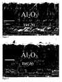
Fig. 1 shows a cross-section SEM image (magnification 10000x) of a typical alumina layer according to the present invention deposited on a MTCVD-Ti(C,N) layer. The alumina layer is composed of columnar grains. It is dense with no detectable porosity.Fig. 2 shows a cross-section SEM image of a typical layer according the prior-art (magnification 6000x) deposited on a MTCVD-Ti(C,N) layer. The alumina layer is composed of large nearly equiaxed grains. Porosity is visible in the alumina layer. Interfacial porosity between the alumina layer and the Ti(C,N) layer is also visible.- A method to deposit α-Al2O3 with a strong (116) texture in a temperature range of 750 to 1000°C is described. The invention is utilising short pulses of precursors followed by purging steps with an inert gas such as Ar. After the purge another precursor is applied as a short pulse. In addition to the texture control the method can be used to produce finer grain sizes by increasing the number of nucleation sites. The texture-controlled α-Al2O3 layers deposited at medium temperature (about 800°C) show enhanced toughness.
- Al2O3 layers according to this invention outperform the prior-art and are especially suitable be used in toughness demanding stainless steel cutting applications such as interrupted cutting, turning with coolant and especially intermittent turning with coolant. The other application area is to cut cast iron where the edge strength of this kind of alumina layer is superior to the prior art.
- Ti(C,N) layer is used as an intermediate layer, which can be obtained either by conventional CVD or MTCVD, preferably by MTCVD. This invention makes it possible to deposit α-Al2O3 at the same temperature as is used to deposit the intermediate MTCVD Ti(C,N) layer. Consequently, the heating-up period can be omitted after MTCVD.
- To nucleate α-Al2O3 with the specified (116) texture several steps are needed. First, on the Ti(C,N) layer a bonding layer characterised by the presence of an Al concentration gradient is deposited. Nitrogen and CH3CN are applied during deposition of this bonding layer. The aluminium content on the surface of this layer being considerably, about 30%, higher than in the bonding layer according to
US 5,137,774 (prior-art) and the bonding layer is obviously containing nitrogen. The surface of this bonding layer is subjected to an additional treatment(s). - Nucleation is started with a TiCl4/AlCl3/H2 pulse with high TiCl4 content (5-15%) and with a duration of 2-60 minutes. After that an Ar purge (
duration 5 minutes) is applied in order to remove excess Cl- from the surface. After this an oxidising pulse is applied using a CO2/H2/N2/Ar (N2 = about 15-17%, Ar=balance) gas mixture The oxidising step has to be relatively short, about 0.5-5 minutes to secure (116) nucleation. The key to obtain the specified growth texture is the control of the oxidation potential of the CO2/H2/N2/Ar mixture by adjustment of the N2:CO2 ratio. This ratio should be 250-400, preferably 300-350. The use of controlled oxygen potential in combination with the correct time and number of pulses enables the correct nucleation mode. Typical pulse times may range from 0.5 to 5 minutes depending on the duration of the pulse. The oxidising pulse is again followed by an Ar purge. These steps can be repeated several times, preferably 2-5 times, in sequence to increase the amount of α-Al2O3 nuclei. Too low or excessive oxidation must be avoided. A person skilled in the art can find the best and optimised combination between the duration and the amount of the steps. - 1. Depositing a bonding layer 0.1-1 µm thick in a gas mixture of 2-3 % TiCl4 and AlCl3 increasing from 0.5 to 6 %, 3-7 % CO, 1-3 % CO2, 0.2-1.0% CH3CN 0.2-1.0%, 2-10 % N2 and balance H2 at about 750-1000 °C, preferably at 800°C and at a pressure of 50-200 mbar.
- 2. Purging by Ar for 5 min.
- 3. Treating the bonding layer in a gas mixture of 5-15 % TiCl4 and 2-4% AlCl3) in hydrogen for 2-60 min at 750-1000°C, preferably at 800 °C and at a pressure of 50-200 mbar.
- 4. Purging by Ar for 5 min.
- 5. Treating in a gas mixture of 0.05 to 0.1% CO2 (preferably 0.05%), 10 to 40% N2 (preferably 15.0-17.5% at CO2 = 0.05%), 10% H2, balance Ar at a pressure of 50-200 mbar for 0.5-5 minutes at a temperature of 750-1000°C depending on the temperature for the subsequent deposition of the alumina layer.
- 6. Purging by Ar for 5 min.
- 7. Repeating steps 3-6 to obtain the optimum oxidisation level.
- 8. Depositing an alumina layer at a temperature of 950-1000°C with desired thickness according to known technique or depositing an alumina layer at 750-950 using higher deposition pressures (200-500mbar) together with higher amounts (0.5-1.5%) of catalysing precursors such as H2S or SOx, preferably H2S.
The growth of the alumina layer onto the nucleation layer is started by sequencing the reactant gases in the following order: CO, AlCl3, CO2. Process temperatures of 750 to 1000°C can be used since the texture is determined by the nucleation surface. - The present invention relates to a cutting tool insert, as set forth in claim 1, consisting of a substrate at least partially coated with a coating with a total thickness of 15-40 µm, preferably 20-25 µm consisting of one or more refractory layers of which at least one layer is an alpha alumina layer. The α-Al2O3 layer deposited according to this invention is dense and exhibits a very low defect density. It is composed of columnar grains with a strong (116) texture. The columnar grains have a length/width ratio of from 2 to 15, preferably 5 to 8.
- The texture coefficients (TC) for the α-Al2O3 according to this invention layer is determined as follows:

where - I(hkl) = intensity of the (hkl) reflection
- Io(hkl) = standard intensity according to JCPDS card no 46-1212
- n = number of reflections used in the calculation
- (hkl) reflections used are: (012), (104), (110), (113), (024), (116).
- The texture of the alumina layer is defined as follows:
- TC(116) > 1.8, preferably >2.0 and most preferably >3.0 and simultaneously TC(012), TC(113), TC(024) all< 1.5, preferably <1.0 and most preferably <0.5. Note that the intensities of the related (012) and (024) reflections are also low. However, for this growth mode TC(104) is somewhat higher than the other background reflections but should be <1.5, preferably <1.0 and most preferably <0.5 or at least obey the following: TC(104) < 0.6x TC(116), preferably less than 0.3xTC(116).
- The substrate comprises a hard material such as cemented carbide, cermets, ceramics, high speed steel or a superhard material such as cubic boron nitride (CBN) or diamond preferably cemented carbide or CBN. By CBN is herein meant a cutting tool material containing at least 40 vol-% CBN. In a preferred embodiment the substrate is a cemented carbide with a binder phase enriched surface zone.
- The coating comprises a first layer adjacent the body of CVD Ti(C,N), CVD TiN, CVD TiC, MTCVD Ti(C,N), MTCVD Zr(C,N), MTCVD Ti(B,C,N), CVD HfN or combinations thereof preferably of Ti(C,N) having a thickness of from 1 to 20 µm, preferably from 1 to 10 µm and the α-Al2O3 layer adjacent the first layer having a thickness of from about 1 to 40 µm, preferably from 1 to 20 µm, most preferably from 1 to 10 µm. Preferably there is an intermediate layer of TiN between the substrate and the first layer with a thickness of <3 µm, preferably 0.5-2 µm.
- In one embodiment the α-Al2O3 layer is the uppermost layer
- In another embodiment there is a layer of carbide, nitride, carbonitride or carboxynitride of one or more of Ti, Zr and Hf, having a thickness of from about 0.5 to 3 µm, preferably 0.5 to 1.5 µm atop the α-Al2O3 layer. Alternatively this layer has a thickness of from about 1 to 20 µm, preferably 2 to 8 µm.
- In yet another embodiment the coating includes a layer of κ-Al2O3 and/or γ-Al2O3 preferably atop the α-Al2O3. with a thickness of from 0.5 to 10, preferably from 1 to 5 µm.
- Cemented carbide cutting inserts with a composition of 5.9% Co and balance WC (hardness about 1600 HV) were coated with a layer of MTCVD Ti(C,N). The thickness of the MTCVD layer was about 2 µm. On to this layer three different alumina layers consisting of about 10 µm α-Al2O3 were deposited:
- Layer a) contained a (116) textured layer and was deposited according to the present invention. The detailed process data is given in Table 1.
- Layer b) was deposited according to the prior art.
- Layer c) was deposited according to the present invention at 800°C. The detailed process data is given in Table 2.
- Layers a), b) and c) were studied using X-ray diffraction. The texture coefficients were determined are presented in Table 3. As clear from Table 2. TC(104) is somewhat higher than the other background reflections.
Table 3. hkl Invention, Layer a Prior art, Layer b Invention, Layer c 012 0.29 0.97 0.74 104 0.59 1.10 0.97 110 0.45 0.95 0.20 113 0.37 0.99 0.15 024 0.41 0.96 0.51 116 3.89 1.03 3.43 - Layers a) and b) were studied using Scanning electron microscopy. The cross section images of the coatings are shown in
Figs.1 and 2 , respectively. The differences in microstructure and morphology are clear. - The layers a) and b) from the Example 1 were tested with respect to edge chipping in longitudinal turning in cast iron.
Work piece: Cylindrical bar Material: SS0130 Insert type: SNUN Cutting speed: 400 m/min Feed: 0.4 mm/rev Depth of cut: 2.0 mm Remarks: dry turning - The inserts were inspected after 2 and 4 minutes of cutting. As clear from Table 4 the edge toughness of the prior art product was considerably enhanced when the layer was produced according to this invention.
Table 4 Flaking of the edge line (%) Flaking of the edge line (%) after 2 minutes After 6 minutes Layer a (Invention) 0 5 Layer b 16 32 - The layer produced according to this invention was compared with a market leader, referred to here as Competitor X. This coating is composed of MTCVD Ti(C,N) and α-Al2O3. XRD was used to determine the texture coefficients for these competitor coatings. Two inserts from Competitor X were randomly chosen for XRD. Table 5 shows the obtained TCs for the Competitor X. The alumina layer from Competitor X exhibit a random texture and can be compared with the present invention with strong (116) texture, Table 3.
Table 5 Hkl TC(hkl) 012 0.59 0.57 104 0.92 0.88 110 1.71 1.90 113 0.48 0.42 024 1.12 1.12 116 1.02 1.01 - Two inserts produced according to this invention were compared with the two Competitor X inserts with respect to wear resistance in turning of ball bearing material
Work piece: Cylindrical tubes (Ball bearings) Material: SS2258 Insert type: WNMG080416 Cutting speed: 500 m/min Feed: 0.5 mm/rev Depth of cut: 1.0 mm Remarks: Dry turning Tool life criterion: Flank wear > 0.3 mm, three edges of each variant were tested. Results: Tool life (min) Layer a 32.2 (invention) Layer a 29.5 (invention) Competitor 1 14.5 (prior art) Competitor 2 15.5 (prior art) - Layer a), b) and c) deposited on Co-enriched substrates were tested with respect to toughness in longitudinal turning with interrupted cuts.
Work piece: Cylindrical slotted bar Material: SS1672 Insert type: CNMG120408-M3 Cutting speed: 140 m/min Feed: 0.1, 0.125, 0.16, 0.20, 0.25, 0.315, 0.4, 0.5, 0.63, 0.8 mm/rev gradually increased after 10 mm length of cut Depth of cut: 2.5 mm Remarks: dry turning Tool life criteria: Gradually increased feed until edge breakage. 10 edges of each variant were tested. Table 6 Mean feed at breakage (mm/rev) Layer a (invention) 0.40 Layer b (prior art) 0.12 Layer c (invention) 0.40 - The test results show (Table 6) that layers according to the invention exhibited clearly better toughness behaviour than the prior-art (Layer b).
- Cubic boron nitride (CBN) insert containing about 90 % of polycrystalline CBN (PCBN) were coated according to this invention and according to prior art layer discussed in Example1. The coated CBN was compared with uncoated CBN insert in cutting of steel containing ferrite. It is known that B has a high affinity to ferrite and diffusion wear occurs at high cutting speeds. As shown in Table 7 the layer according to this invention is superior to the prior art.
Work piece: Cylindrical bar Material: SS0130 Insert type: SNUN Cutting speed: 800 m/min Feed: 0.4 mm/rev Depth of cut: 2.5 mm Remarks: dry turning Table 7 Life time (min) Coated CBN (Invention, layer c) 22 Coated according to prior art 11 Uncoated CBN 9

| Step 1: Bonding layer | ||
| Gas mixture | TiCl4 | = 2.8% |
| AlCl3 | = increasing | |
| from 0.8 to 5.2% | ||
| CH3CN | = 0.5 % | |
| CO | = 5.8% | |
| CO2 | = 2.2 % | |
| N2 | = 5% | |
| Balance: | H2 | |
| Duration | 40 | |
| Temperature | ||
| 1000° | ||
| Pressure | ||
| 100 mbar | ||
| Step 2: Purge | ||
| Gas | Ar | =100 |
| Duration | ||
| 5 min | ||
| Temperature | 1000 C | |
| Pressure | 50 mbar | |
| Step 3: Pulse 1 | ||
| Gas mixture | TiCl4 | = 12.5% |
| AlCl3 | = 2.8 | |
| H2 | = | |
| Duration | ||
| 5 min. | ||
| Temperature | 1000 C | |
| Pressure | 50 mbar | |
| Step 4: Purge | ||
| Gas | Ar | =100 |
| Duration | ||
| 5 min | ||
| Temperature | 1000 C | |
| Pressure | 50 mbar | |
| Step 5: Pulse 2 | ||
| Gas mixture | CO2 | = 0.05% |
| N2 | = 16% | |
| H2 | = 10% | |
| Balance: | Ar | |
| Duration | 1 | |
| Temperature | ||
| 1000 ° | ||
| Pressure | ||
| 100 mbar | ||
| Step 6: Purge | ||
| Gas | Ar | =100 |
| Duration | ||
| 5 min | ||
| Temperature | 1000 C | |
| Pressure | 50 mbar | |
| Step 7: Nucleation step | ||
| Gas mixture | AlCl3 | = 3,2 % |
| HCl | = 2.0 % | |
| CO2 | = 1.9 % | |
| Balance | H2 | |
| Duration | 60 | |
| Temperature | ||
| 1000 °C | ||
| Pressure | 210 mbar | |
| Step 8: Deposition | ||
| Gas mixture | AlCl3 | = 4.2 % |
| HCl | = 1.0 % | |
| CO2 | = 2.1% | |
| H2S | = 0.2% | |
| Balance: | H2 | |
| Duration | 520 | |
| Temperature | ||
| 1000 °C | ||
| Pressure | 50 mbar | |
| Steps 3-6 were repeated 3 times. |
| Step 1: Bonding layer | ||
| Gas mixture | TiCl4 | = 2.8% |
| CH3CN | = 0.7% | |
| AlCl3 | = increasing | |
| from 0.8 to 5.4% | ||
| CO | = 5.8% | |
| CO2 | = 2.2 % | |
| N2 | = 5% | |
| Balance: | H2 | |
| Duration | 40 min | |
| Temperature | 780° | |
| Pressure | ||
| 100 mbar | ||
| Step 2: Purge | ||
| Gas | Ar | =100 |
| Duration | ||
| 5 min | ||
| Temperature | 780°C | |
| Pressure | 50 mbar | |
| Step 3: Pulse 1 | ||
| Gas mixture | TiCl4 | = 12.5% |
| AlCl3 | = 2.5 | |
| H2 | = | |
| Duration | ||
| 5 min. | ||
| Temperature | 780°C | |
| Pressure | 50 mbar | |
| Step 4: Purge | ||
| Gas | Ar | =100 |
| Duration | ||
| 5 min | ||
| Temperature | 780°C | |
| Pressure | 50 mbar | |
| Step 5: Pulse 2 | ||
| Gas mixture | CO2 | = 0.05% |
| N2 | = 17% | |
| H2 | = 10% | |
| Balance: | Ar | |
| Duration | 2 min | |
| Temperature | 780° | |
| Pressure | ||
| 100 mbar | ||
| Step 6: Purge | ||
| Gas | Ar | =100 |
| Duration | ||
| 5 min | ||
| Temperature | 780°C | |
| Pressure | 50 mbar | |
| Step 7: Nucleation step | ||
| Gas mixture | AlCl3 | = 3,2 % |
| HCl | = 2.0 % | |
| CO2 | = 1.9 % | |
| Balance | H2 | |
| Duration | 60 min | |
| Temperature | 780°C | |
| Pressure | 50 mbar | |
| Step 8: Deposition | ||
| Gas mixture | AlCl3 | = 4.1 % |
| HCl | = 1.0 % | |
| CO2 | = 2.5% | |
| H2S | = 0.9% | |
| Balance: | H2 | |
| Duration | 600 min | |
| Temperature | 780°C | |
| Pressure | 350 mbar | |
| Steps 3-6 were repeated three times. |
Claims (9)
- Cutting tool insert consisting of a substrate at least partially coated with a coating with a total thickness of 10-40 µm, preferably 15-25 µm consisting of one or more refractory layers of which at least one layer is an alumina layercharacterized in the alumina layer being composed of columnar α-Al2O3 grains with texture coefficientsa) TC(116) >1.8, preferably >2.0 and most preferably >3.0.b) TC(012), TC(104), TC(110), TC(113), TC(024) all< 1.5, preferably <1.0 and most preferably <0.5the texture coefficient TC(hkj) being defined as

whereI(hkl) = measured intensity of the (hkl) reflectionIo(hkl) = standard intensity according to JCPDS card no 46-1212n = number of reflections used in the calculation(hkl) reflections used are: (012), (104), (110), (113), (024), (116),wherein the coating comprises a first layer adjacent the substrate of Ti(C,N) and a bonding layer including an Al concentration gradient deposited on the first layer. - Cutting tool insert according to claim 1characterized in the alumina layer being composed of columnar grains with the length/width ratio from 2 to 15, preferably 5 to 8.
- Cutting tool insert according to any of the previous claimscharacterized in that the substrate comprises cemented carbide preferably with a binder phase enriched surface zone, CBN or sintered CBN alloy.
- Cutting tool insert according to any of the previous claimscharacterized in that the coating comprises a first layer adjacent the body of CVD Ti(C,N), CVD TiN, CVD TiC, MTCVD Ti(C,N), MTCVD Zr(C,N), MTCVD Ti(B,C.N), CVD HfN or combinations thereof preferably of Ti(C,N) having a thickness of from 1 to 20 µm, preferably from 1 to 10 µm and the α-Al2O3 layer adjacent the first layer having a thickness of from about 1 to 40 µm, preferably from I to 20 µm, most preferably from 1 to 10 µm.
- Cutting tool insert according to any of the previous claimscharacterized in that the α-Al2O3 layer is the uppermost layer.
- Cutting tool insert according to any of the previous claimscharacterized in that a layer of carbide, nitride, carbonitride or carboxynitride of one or more of Ti, Zr and Hf, having a thickness of from about 0.5 to 12 µm, preferably 0.5 to 6 µm atop the α-Al2O3 layer.
- Cutting tool insert according to any of the previous claimscharacterized in a layer of κ-Al2O3 or γ-Al2Q3 atop the α-Al2O3 with a thickness of from 0.5 to 10 µm, preferably from 1 to 5 µm.
- Cutting tool insert according to any of the previous claims,characterized in a layer of TiN between the substrate and the first layer with a thickness of <3 µm, preferably 0.5-2 µm.
- Cutting tool insert according to any of the previous claimscharacterized in that the substrate comprises a cemented carbide with a binder phase enriched surface zone.

Applications Claiming Priority (1)
| Application Number | Priority Date | Filing Date | Title |
|---|---|---|---|
| SE0402692ASE528431C2 (en) | 2004-11-05 | 2004-11-05 | With aluminum oxide coated cutting tool inserts and method of making this |
Publications (2)
| Publication Number | Publication Date |
|---|---|
| EP1655392A1 EP1655392A1 (en) | 2006-05-10 |
| EP1655392B1true EP1655392B1 (en) | 2008-04-16 |
Family
ID=33488164
Family Applications (1)
| Application Number | Title | Priority Date | Filing Date |
|---|---|---|---|
| EP20050445084Not-in-forceEP1655392B1 (en) | 2004-11-05 | 2005-10-26 | Alumina layer with enhanced texture |
Country Status (5)
| Country | Link |
|---|---|
| US (2) | US7455900B2 (en) |
| EP (1) | EP1655392B1 (en) |
| AT (1) | ATE392497T1 (en) |
| DE (1) | DE602005006071T2 (en) |
| SE (1) | SE528431C2 (en) |
Cited By (2)
| Publication number | Priority date | Publication date | Assignee | Title |
|---|---|---|---|---|
| US7989060B2 (en) | 2008-03-07 | 2011-08-02 | Seco Tools Ab | Oxide coated cutting insert |
| US7989059B2 (en) | 2008-03-07 | 2011-08-02 | Seco Tools Ab | Oxide coated cutting insert |
Families Citing this family (31)
| Publication number | Priority date | Publication date | Assignee | Title |
|---|---|---|---|---|
| SE528430C2 (en)* | 2004-11-05 | 2006-11-14 | Seco Tools Ab | With aluminum oxide coated cutting tool inserts and method of making this |
| SE528432C2 (en) | 2004-11-05 | 2006-11-14 | Seco Tools Ab | With aluminum oxide coated cutting tool inserts and method for making this |
| EP1905870A3 (en) | 2006-09-27 | 2008-05-14 | Seco Tools Ab | Alumina layer with enhanced texture |
| SE532023C2 (en)* | 2007-02-01 | 2009-09-29 | Seco Tools Ab | Textured hardened alpha-alumina coated cutting for metalworking |
| SE531670C2 (en)* | 2007-02-01 | 2009-06-30 | Seco Tools Ab | Textured alpha-alumina coated cutting for metalworking |
| SE531929C2 (en)* | 2007-07-13 | 2009-09-08 | Seco Tools Ab | Coated cemented carbide inserts for turning steel or stainless steel |
| WO2009107648A1 (en)* | 2008-02-27 | 2009-09-03 | 京セラ株式会社 | Surface coated member and cutting tool |
| SE532049C2 (en) | 2008-03-07 | 2009-10-13 | Seco Tools Ab | Oxide coated cutting tool cutter for chip separating machining of steel |
| SE532050C2 (en) | 2008-03-07 | 2009-10-13 | Seco Tools Ab | Oxide coated cutting tool cutter for chip separating machining of steel |
| EP2497590B1 (en)* | 2009-11-06 | 2017-03-01 | Tungaloy Corporation | Coated tool |
| EP2395126A1 (en) | 2010-06-08 | 2011-12-14 | Seco Tools AB | Textured alumina layer |
| EP2446988A1 (en)* | 2010-10-29 | 2012-05-02 | Seco Tools AB | Cutting tool insert with an alpha-alumina layer having a multi-components texture |
| WO2012079769A1 (en) | 2010-12-17 | 2012-06-21 | Seco Tools Ab | Coated cubic boron nitride tool for machining applications |
| US8507082B2 (en) | 2011-03-25 | 2013-08-13 | Kennametal Inc. | CVD coated polycrystalline c-BN cutting tools |
| EP2570510B2 (en)* | 2011-09-16 | 2019-02-13 | Walter AG | Sulfur containing alpha-alumina coated cutting tool |
| ES2728705T3 (en) | 2011-09-16 | 2019-10-28 | Walter Ag | Alpha-alumina coated cutting tool designed with grain boundaries |
| US9970104B2 (en)* | 2013-08-27 | 2018-05-15 | Kyocera Corporation | Coated tool |
| WO2015093530A1 (en)* | 2013-12-17 | 2015-06-25 | 京セラ株式会社 | Coated tool |
| BR112016017381B1 (en) | 2014-01-30 | 2022-03-08 | Sandvik Intellectual Property Ab | ALUMINA COATED CUTTING TOOL |
| ES2586479T3 (en) | 2014-01-30 | 2016-10-14 | Walter Ag | Alumina coated cutting tool with zigzag alumina grain boundaries |
| CN106102973B (en)* | 2014-03-22 | 2018-01-26 | 京瓷株式会社 | Coated tools and cutting tools |
| WO2016031741A1 (en)* | 2014-08-28 | 2016-03-03 | 京セラ株式会社 | Coated tool |
| CN106715012B (en)* | 2014-09-24 | 2018-10-23 | 京瓷株式会社 | Coated tool |
| US9890084B2 (en)* | 2015-10-01 | 2018-02-13 | Kennametal Inc. | Hybrid nanocomposite coatings and applications thereof |
| JP6229911B1 (en)* | 2016-10-19 | 2017-11-15 | 株式会社タンガロイ | Coated cutting tool |
| JP6229912B1 (en)* | 2016-10-21 | 2017-11-15 | 株式会社タンガロイ | Coated cutting tool |
| WO2018092518A1 (en)* | 2016-11-17 | 2018-05-24 | 株式会社タンガロイ | Coated cutting tool |
| WO2018128003A1 (en)* | 2017-01-07 | 2018-07-12 | 株式会社タンガロイ | Coated cutting tool |
| CN110431254A (en)* | 2017-04-07 | 2019-11-08 | 山特维克知识产权股份有限公司 | Coated cutting tool |
| EP3848484A3 (en) | 2020-01-10 | 2021-09-15 | Sakari Ruppi | Improved alumina layer deposited at low temperature |
| EP3848485A1 (en) | 2020-01-10 | 2021-07-14 | Sakari Ruppi | Improved alpha alumina layer deposited with controlled textures |
Family Cites Families (26)
| Publication number | Priority date | Publication date | Assignee | Title |
|---|---|---|---|---|
| DE8000947U1 (en)* | 1980-01-16 | 1981-07-09 | Komet Stahlhalter- Und Werkzeugfabrik Robert Breuning Gmbh, 7122 Besigheim | IN A HOLDER OF A MACHINE TOOL, ESPECIALLY TURNING TOOL, INSERTABLE INSERT HOLDER |
| US4619866A (en)* | 1980-07-28 | 1986-10-28 | Santrade Limited | Method of making a coated cemented carbide body and resulting body |
| US4927301A (en)* | 1988-12-27 | 1990-05-22 | Gte Valenite Corporation | Adjustable boring bar cartridge |
| EP0408535B1 (en) | 1989-07-13 | 1994-04-06 | Seco Tools Ab | Multi-oxide coated carbide body and method of producing the same |
| US5238150A (en)* | 1991-02-01 | 1993-08-24 | William Dispenser Corporation | Dispenser with compressible piston assembly for expelling product from a collapsible reservoir |
| EP0556422A1 (en)* | 1991-02-11 | 1993-08-25 | Valenite Inc. | Improved adjustable boring bar |
| US5156501A (en)* | 1991-08-07 | 1992-10-20 | Gte Valenite Corporation | Adjustable torsion bar cartridge for face mills |
| SE501527C2 (en) | 1992-12-18 | 1995-03-06 | Sandvik Ab | Methods and articles when coating a cutting tool with an alumina layer |
| US5320458A (en)* | 1993-05-24 | 1994-06-14 | Valenite Inc. | Cutting tool having a cutter cartridge adjustable around two adjustment axes |
| SE502174C2 (en)* | 1993-12-23 | 1995-09-04 | Sandvik Ab | Methods and articles when coating a cutting tool with an alumina layer |
| SE502223C2 (en)* | 1994-01-14 | 1995-09-18 | Sandvik Ab | Methods and articles when coating a cutting tool with an alumina layer |
| SE514695C2 (en)* | 1995-07-14 | 2001-04-02 | Sandvik Ab | Cutting tool coated with alumina and method for its manufacture |
| SE514177C2 (en) | 1995-07-14 | 2001-01-15 | Sandvik Ab | Coated cemented carbide inserts for intermittent machining in low alloy steel |
| DE69720561T2 (en)* | 1996-01-10 | 2003-11-27 | Mitsubishi Materials Corp., Tokio/Tokyo | Process for the production of coated cutting inserts |
| JPH1068077A (en)* | 1996-08-26 | 1998-03-10 | Mitsubishi Materials Corp | Production of cutting tool made of surface-coated cemented carbide excellent in chipping resistance |
| US5913643A (en)* | 1997-04-22 | 1999-06-22 | Kennametal Inc. | Adjustable lead angle chamfering toolholder |
| JP3573256B2 (en)* | 1998-07-27 | 2004-10-06 | 住友電気工業株式会社 | Al2O3-coated cBN-based sintered compact cutting tool |
| JP3678924B2 (en) | 1998-11-05 | 2005-08-03 | 日立ツール株式会社 | Aluminum oxide coated tool |
| US6238150B1 (en)* | 1999-10-29 | 2001-05-29 | Mitsubishi Materials Corporation | Drilling tool |
| DE19962056A1 (en)* | 1999-12-22 | 2001-07-12 | Walter Ag | Cutting tool with multi-layer, wear-resistant coating |
| US6572991B1 (en) | 2000-02-04 | 2003-06-03 | Seco Tools Ab | Deposition of γ-Al2O3 by means of CVD |
| SE519339C2 (en)* | 2000-11-22 | 2003-02-18 | Sandvik Ab | Cutting tools coated with alumina and ways of manufacturing the same |
| SE522736C2 (en) | 2001-02-16 | 2004-03-02 | Sandvik Ab | Aluminum-coated cutting tool and method for making the same |
| SE525581C2 (en) | 2002-05-08 | 2005-03-15 | Seco Tools Ab | Cutting coated with alumina made with CVD |
| SE528430C2 (en)* | 2004-11-05 | 2006-11-14 | Seco Tools Ab | With aluminum oxide coated cutting tool inserts and method of making this |
| SE528432C2 (en)* | 2004-11-05 | 2006-11-14 | Seco Tools Ab | With aluminum oxide coated cutting tool inserts and method for making this |
- 2004
- 2004-11-05SESE0402692Apatent/SE528431C2/ennot_activeIP Right Cessation
- 2005
- 2005-10-26DEDE200560006071patent/DE602005006071T2/enactiveActive
- 2005-10-26ATAT05445084Tpatent/ATE392497T1/enactive
- 2005-10-26EPEP20050445084patent/EP1655392B1/ennot_activeNot-in-force
- 2005-11-02USUS11/264,382patent/US7455900B2/ennot_activeExpired - Fee Related
- 2008
- 2008-09-12USUS12/232,227patent/US7695764B2/ennot_activeExpired - Fee Related
Cited By (2)
| Publication number | Priority date | Publication date | Assignee | Title |
|---|---|---|---|---|
| US7989060B2 (en) | 2008-03-07 | 2011-08-02 | Seco Tools Ab | Oxide coated cutting insert |
| US7989059B2 (en) | 2008-03-07 | 2011-08-02 | Seco Tools Ab | Oxide coated cutting insert |
Also Published As
| Publication number | Publication date |
|---|---|
| SE528431C2 (en) | 2006-11-14 |
| US20090061091A1 (en) | 2009-03-05 |
| SE0402692L (en) | 2006-05-06 |
| US7455900B2 (en) | 2008-11-25 |
| ATE392497T1 (en) | 2008-05-15 |
| EP1655392A1 (en) | 2006-05-10 |
| US7695764B2 (en) | 2010-04-13 |
| SE0402692D0 (en) | 2004-11-05 |
| US20060141271A1 (en) | 2006-06-29 |
| DE602005006071D1 (en) | 2008-05-29 |
| DE602005006071T2 (en) | 2009-05-14 |
Similar Documents
| Publication | Publication Date | Title |
|---|---|---|
| EP1655392B1 (en) | Alumina layer with enhanced texture | |
| EP1655387B1 (en) | Enhanced alumina layer with texture | |
| US7914849B2 (en) | Alumina layer with controlled texture | |
| US6713172B2 (en) | Oxide coated cutting tool | |
| US7163735B2 (en) | Enhanced alumina layer produced by CVD | |
| US5674564A (en) | Alumina-coated sintered body | |
| US7993742B2 (en) | Alumina layer with enhanced texture | |
| EP0738336B1 (en) | Oxide coated cutting tool | |
| EP1008673B1 (en) | Improved coating for cutting tool applied for cast iron | |
| EP0408535B1 (en) | Multi-oxide coated carbide body and method of producing the same | |
| EP0753602B1 (en) | Oxide coated cutting tool | |
| US8343620B2 (en) | Alumina coated grade | |
| EP1905870A2 (en) | Alumina layer with enhanced texture | |
| JPH06316758A (en) | Coating material body | |
| EP1477581A1 (en) | Enhanced alumina layer produced by CVD | |
| EP3848484A2 (en) | Improved alumina layer deposited at low temperature |
Legal Events
| Date | Code | Title | Description |
|---|---|---|---|
| PUAI | Public reference made under article 153(3) epc to a published international application that has entered the european phase | Free format text:ORIGINAL CODE: 0009012 | |
| 17P | Request for examination filed | Effective date:20051104 | |
| AK | Designated contracting states | Kind code of ref document:A1 Designated state(s):AT BE BG CH CY CZ DE DK EE ES FI FR GB GR HU IE IS IT LI LT LU LV MC NL PL PT RO SE SI SK TR | |
| AX | Request for extension of the european patent | Extension state:AL BA HR MK YU | |
| AKX | Designation fees paid | Designated state(s):AT BE BG CH CY CZ DE DK EE ES FI FR GB GR HU IE IS IT LI LT LU LV MC NL PL PT RO SE SI SK TR | |
| 17Q | First examination report despatched | Effective date:20070416 | |
| GRAP | Despatch of communication of intention to grant a patent | Free format text:ORIGINAL CODE: EPIDOSNIGR1 | |
| GRAS | Grant fee paid | Free format text:ORIGINAL CODE: EPIDOSNIGR3 | |
| GRAA | (expected) grant | Free format text:ORIGINAL CODE: 0009210 | |
| AK | Designated contracting states | Kind code of ref document:B1 Designated state(s):AT BE BG CH CY CZ DE DK EE ES FI FR GB GR HU IE IS IT LI LT LU LV MC NL PL PT RO SE SI SK TR | |
| REG | Reference to a national code | Ref country code:CH Ref legal event code:EP | |
| REG | Reference to a national code | Ref country code:IE Ref legal event code:FG4D | |
| REF | Corresponds to: | Ref document number:602005006071 Country of ref document:DE Date of ref document:20080529 Kind code of ref document:P | |
| REG | Reference to a national code | Ref country code:SE Ref legal event code:TRGR | |
| REG | Reference to a national code | Ref country code:CH Ref legal event code:NV Representative=s name:BOVARD AG PATENTANWAELTE | |
| PG25 | Lapsed in a contracting state [announced via postgrant information from national office to epo] | Ref country code:SI Free format text:LAPSE BECAUSE OF FAILURE TO SUBMIT A TRANSLATION OF THE DESCRIPTION OR TO PAY THE FEE WITHIN THE PRESCRIBED TIME-LIMIT Effective date:20080416 | |
| NLV1 | Nl: lapsed or annulled due to failure to fulfill the requirements of art. 29p and 29m of the patents act | ||
| PG25 | Lapsed in a contracting state [announced via postgrant information from national office to epo] | Ref country code:PT Free format text:LAPSE BECAUSE OF FAILURE TO SUBMIT A TRANSLATION OF THE DESCRIPTION OR TO PAY THE FEE WITHIN THE PRESCRIBED TIME-LIMIT Effective date:20080916 Ref country code:NL Free format text:LAPSE BECAUSE OF FAILURE TO SUBMIT A TRANSLATION OF THE DESCRIPTION OR TO PAY THE FEE WITHIN THE PRESCRIBED TIME-LIMIT Effective date:20080416 Ref country code:FI Free format text:LAPSE BECAUSE OF FAILURE TO SUBMIT A TRANSLATION OF THE DESCRIPTION OR TO PAY THE FEE WITHIN THE PRESCRIBED TIME-LIMIT Effective date:20080416 Ref country code:ES Free format text:LAPSE BECAUSE OF FAILURE TO SUBMIT A TRANSLATION OF THE DESCRIPTION OR TO PAY THE FEE WITHIN THE PRESCRIBED TIME-LIMIT Effective date:20080727 Ref country code:BG Free format text:LAPSE BECAUSE OF FAILURE TO SUBMIT A TRANSLATION OF THE DESCRIPTION OR TO PAY THE FEE WITHIN THE PRESCRIBED TIME-LIMIT Effective date:20080716 | |
| PG25 | Lapsed in a contracting state [announced via postgrant information from national office to epo] | Ref country code:LV Free format text:LAPSE BECAUSE OF FAILURE TO SUBMIT A TRANSLATION OF THE DESCRIPTION OR TO PAY THE FEE WITHIN THE PRESCRIBED TIME-LIMIT Effective date:20080416 Ref country code:PL Free format text:LAPSE BECAUSE OF FAILURE TO SUBMIT A TRANSLATION OF THE DESCRIPTION OR TO PAY THE FEE WITHIN THE PRESCRIBED TIME-LIMIT Effective date:20080416 | |
| PG25 | Lapsed in a contracting state [announced via postgrant information from national office to epo] | Ref country code:IS Free format text:LAPSE BECAUSE OF FAILURE TO SUBMIT A TRANSLATION OF THE DESCRIPTION OR TO PAY THE FEE WITHIN THE PRESCRIBED TIME-LIMIT Effective date:20080816 | |
| ET | Fr: translation filed | ||
| PG25 | Lapsed in a contracting state [announced via postgrant information from national office to epo] | Ref country code:DK Free format text:LAPSE BECAUSE OF FAILURE TO SUBMIT A TRANSLATION OF THE DESCRIPTION OR TO PAY THE FEE WITHIN THE PRESCRIBED TIME-LIMIT Effective date:20080416 Ref country code:LT Free format text:LAPSE BECAUSE OF FAILURE TO SUBMIT A TRANSLATION OF THE DESCRIPTION OR TO PAY THE FEE WITHIN THE PRESCRIBED TIME-LIMIT Effective date:20080416 | |
| PLBE | No opposition filed within time limit | Free format text:ORIGINAL CODE: 0009261 | |
| STAA | Information on the status of an ep patent application or granted ep patent | Free format text:STATUS: NO OPPOSITION FILED WITHIN TIME LIMIT | |
| PG25 | Lapsed in a contracting state [announced via postgrant information from national office to epo] | Ref country code:BE Free format text:LAPSE BECAUSE OF FAILURE TO SUBMIT A TRANSLATION OF THE DESCRIPTION OR TO PAY THE FEE WITHIN THE PRESCRIBED TIME-LIMIT Effective date:20080416 Ref country code:RO Free format text:LAPSE BECAUSE OF FAILURE TO SUBMIT A TRANSLATION OF THE DESCRIPTION OR TO PAY THE FEE WITHIN THE PRESCRIBED TIME-LIMIT Effective date:20080416 Ref country code:SK Free format text:LAPSE BECAUSE OF FAILURE TO SUBMIT A TRANSLATION OF THE DESCRIPTION OR TO PAY THE FEE WITHIN THE PRESCRIBED TIME-LIMIT Effective date:20080416 | |
| 26N | No opposition filed | Effective date:20090119 | |
| PG25 | Lapsed in a contracting state [announced via postgrant information from national office to epo] | Ref country code:EE Free format text:LAPSE BECAUSE OF FAILURE TO SUBMIT A TRANSLATION OF THE DESCRIPTION OR TO PAY THE FEE WITHIN THE PRESCRIBED TIME-LIMIT Effective date:20080416 | |
| PG25 | Lapsed in a contracting state [announced via postgrant information from national office to epo] | Ref country code:MC Free format text:LAPSE BECAUSE OF NON-PAYMENT OF DUE FEES Effective date:20081031 | |
| PG25 | Lapsed in a contracting state [announced via postgrant information from national office to epo] | Ref country code:CY Free format text:LAPSE BECAUSE OF FAILURE TO SUBMIT A TRANSLATION OF THE DESCRIPTION OR TO PAY THE FEE WITHIN THE PRESCRIBED TIME-LIMIT Effective date:20080416 | |
| PG25 | Lapsed in a contracting state [announced via postgrant information from national office to epo] | Ref country code:IE Free format text:LAPSE BECAUSE OF NON-PAYMENT OF DUE FEES Effective date:20081028 | |
| PG25 | Lapsed in a contracting state [announced via postgrant information from national office to epo] | Ref country code:HU Free format text:LAPSE BECAUSE OF FAILURE TO SUBMIT A TRANSLATION OF THE DESCRIPTION OR TO PAY THE FEE WITHIN THE PRESCRIBED TIME-LIMIT Effective date:20081017 Ref country code:LU Free format text:LAPSE BECAUSE OF NON-PAYMENT OF DUE FEES Effective date:20081026 | |
| PG25 | Lapsed in a contracting state [announced via postgrant information from national office to epo] | Ref country code:TR Free format text:LAPSE BECAUSE OF FAILURE TO SUBMIT A TRANSLATION OF THE DESCRIPTION OR TO PAY THE FEE WITHIN THE PRESCRIBED TIME-LIMIT Effective date:20080416 | |
| PG25 | Lapsed in a contracting state [announced via postgrant information from national office to epo] | Ref country code:GR Free format text:LAPSE BECAUSE OF FAILURE TO SUBMIT A TRANSLATION OF THE DESCRIPTION OR TO PAY THE FEE WITHIN THE PRESCRIBED TIME-LIMIT Effective date:20080717 | |
| REG | Reference to a national code | Ref country code:CH Ref legal event code:PFA Owner name:SECO TOOLS AB Free format text:SECO TOOLS AB# #737 82 FAGERSTA (SE) -TRANSFER TO- SECO TOOLS AB# #737 82 FAGERSTA (SE) | |
| PGFP | Annual fee paid to national office [announced via postgrant information from national office to epo] | Ref country code:SE Payment date:20121011 Year of fee payment:8 | |
| REG | Reference to a national code | Ref country code:SE Ref legal event code:EUG | |
| PG25 | Lapsed in a contracting state [announced via postgrant information from national office to epo] | Ref country code:SE Free format text:LAPSE BECAUSE OF NON-PAYMENT OF DUE FEES Effective date:20131027 | |
| REG | Reference to a national code | Ref country code:FR Ref legal event code:PLFP Year of fee payment:12 | |
| PGFP | Annual fee paid to national office [announced via postgrant information from national office to epo] | Ref country code:FR Payment date:20160919 Year of fee payment:12 | |
| PGFP | Annual fee paid to national office [announced via postgrant information from national office to epo] | Ref country code:CZ Payment date:20161004 Year of fee payment:12 Ref country code:DE Payment date:20161018 Year of fee payment:12 Ref country code:CH Payment date:20161013 Year of fee payment:12 Ref country code:GB Payment date:20161026 Year of fee payment:12 | |
| PGFP | Annual fee paid to national office [announced via postgrant information from national office to epo] | Ref country code:IT Payment date:20161024 Year of fee payment:12 Ref country code:AT Payment date:20160928 Year of fee payment:12 | |
| REG | Reference to a national code | Ref country code:DE Ref legal event code:R119 Ref document number:602005006071 Country of ref document:DE | |
| REG | Reference to a national code | Ref country code:CH Ref legal event code:PL | |
| REG | Reference to a national code | Ref country code:AT Ref legal event code:MM01 Ref document number:392497 Country of ref document:AT Kind code of ref document:T Effective date:20171026 | |
| GBPC | Gb: european patent ceased through non-payment of renewal fee | Effective date:20171026 | |
| REG | Reference to a national code | Ref country code:FR Ref legal event code:ST Effective date:20180629 | |
| PG25 | Lapsed in a contracting state [announced via postgrant information from national office to epo] | Ref country code:GB Free format text:LAPSE BECAUSE OF NON-PAYMENT OF DUE FEES Effective date:20171026 Ref country code:LI Free format text:LAPSE BECAUSE OF NON-PAYMENT OF DUE FEES Effective date:20171031 Ref country code:CH Free format text:LAPSE BECAUSE OF NON-PAYMENT OF DUE FEES Effective date:20171031 Ref country code:CZ Free format text:LAPSE BECAUSE OF NON-PAYMENT OF DUE FEES Effective date:20171026 Ref country code:DE Free format text:LAPSE BECAUSE OF NON-PAYMENT OF DUE FEES Effective date:20180501 | |
| PG25 | Lapsed in a contracting state [announced via postgrant information from national office to epo] | Ref country code:AT Free format text:LAPSE BECAUSE OF NON-PAYMENT OF DUE FEES Effective date:20171026 Ref country code:FR Free format text:LAPSE BECAUSE OF NON-PAYMENT OF DUE FEES Effective date:20171031 | |
| PG25 | Lapsed in a contracting state [announced via postgrant information from national office to epo] | Ref country code:IT Free format text:LAPSE BECAUSE OF NON-PAYMENT OF DUE FEES Effective date:20171026 |