EP1654994B1 - Apparatus for bone fracture fixation - Google Patents
Apparatus for bone fracture fixationDownload PDFInfo
- Publication number
- EP1654994B1 EP1654994B1EP05022829AEP05022829AEP1654994B1EP 1654994 B1EP1654994 B1EP 1654994B1EP 05022829 AEP05022829 AEP 05022829AEP 05022829 AEP05022829 AEP 05022829AEP 1654994 B1EP1654994 B1EP 1654994B1
- Authority
- EP
- European Patent Office
- Prior art keywords
- bridge region
- bridge
- plate
- bone fixation
- region
- Prior art date
- Legal status (The legal status is an assumption and is not a legal conclusion. Google has not performed a legal analysis and makes no representation as to the accuracy of the status listed.)
- Expired - Lifetime
Links
Images


Classifications
- A—HUMAN NECESSITIES
- A61—MEDICAL OR VETERINARY SCIENCE; HYGIENE
- A61B—DIAGNOSIS; SURGERY; IDENTIFICATION
- A61B17/00—Surgical instruments, devices or methods
- A61B17/56—Surgical instruments or methods for treatment of bones or joints; Devices specially adapted therefor
- A61B17/58—Surgical instruments or methods for treatment of bones or joints; Devices specially adapted therefor for osteosynthesis, e.g. bone plates, screws or setting implements
- A61B17/68—Internal fixation devices, including fasteners and spinal fixators, even if a part thereof projects from the skin
- A61B17/80—Cortical plates, i.e. bone plates; Instruments for holding or positioning cortical plates, or for compressing bones attached to cortical plates
- A61B17/8061—Cortical plates, i.e. bone plates; Instruments for holding or positioning cortical plates, or for compressing bones attached to cortical plates specially adapted for particular bones
- A61B17/8076—Cortical plates, i.e. bone plates; Instruments for holding or positioning cortical plates, or for compressing bones attached to cortical plates specially adapted for particular bones for the ribs or the sternum
- A—HUMAN NECESSITIES
- A61—MEDICAL OR VETERINARY SCIENCE; HYGIENE
- A61B—DIAGNOSIS; SURGERY; IDENTIFICATION
- A61B17/00—Surgical instruments, devices or methods
- A61B17/56—Surgical instruments or methods for treatment of bones or joints; Devices specially adapted therefor
- A61B17/58—Surgical instruments or methods for treatment of bones or joints; Devices specially adapted therefor for osteosynthesis, e.g. bone plates, screws or setting implements
- A61B17/68—Internal fixation devices, including fasteners and spinal fixators, even if a part thereof projects from the skin
- A61B17/80—Cortical plates, i.e. bone plates; Instruments for holding or positioning cortical plates, or for compressing bones attached to cortical plates
- A61B17/8033—Cortical plates, i.e. bone plates; Instruments for holding or positioning cortical plates, or for compressing bones attached to cortical plates having indirect contact with screw heads, or having contact with screw heads maintained with the aid of additional components, e.g. nuts, wedges or head covers
- A61B17/8047—Cortical plates, i.e. bone plates; Instruments for holding or positioning cortical plates, or for compressing bones attached to cortical plates having indirect contact with screw heads, or having contact with screw heads maintained with the aid of additional components, e.g. nuts, wedges or head covers wherein the additional element surrounds the screw head in the plate hole
- A—HUMAN NECESSITIES
- A61—MEDICAL OR VETERINARY SCIENCE; HYGIENE
- A61B—DIAGNOSIS; SURGERY; IDENTIFICATION
- A61B17/00—Surgical instruments, devices or methods
- A61B17/56—Surgical instruments or methods for treatment of bones or joints; Devices specially adapted therefor
- A61B17/58—Surgical instruments or methods for treatment of bones or joints; Devices specially adapted therefor for osteosynthesis, e.g. bone plates, screws or setting implements
- A61B17/68—Internal fixation devices, including fasteners and spinal fixators, even if a part thereof projects from the skin
- A61B17/80—Cortical plates, i.e. bone plates; Instruments for holding or positioning cortical plates, or for compressing bones attached to cortical plates
- A61B17/8052—Cortical plates, i.e. bone plates; Instruments for holding or positioning cortical plates, or for compressing bones attached to cortical plates immobilised relative to screws by interlocking form of the heads and plate holes, e.g. conical or threaded
- A—HUMAN NECESSITIES
- A61—MEDICAL OR VETERINARY SCIENCE; HYGIENE
- A61B—DIAGNOSIS; SURGERY; IDENTIFICATION
- A61B17/00—Surgical instruments, devices or methods
- A61B17/56—Surgical instruments or methods for treatment of bones or joints; Devices specially adapted therefor
- A61B17/58—Surgical instruments or methods for treatment of bones or joints; Devices specially adapted therefor for osteosynthesis, e.g. bone plates, screws or setting implements
- A61B17/68—Internal fixation devices, including fasteners and spinal fixators, even if a part thereof projects from the skin
- A61B17/84—Fasteners therefor or fasteners being internal fixation devices
- A61B17/86—Pins or screws or threaded wires; nuts therefor
- A61B17/8685—Pins or screws or threaded wires; nuts therefor comprising multiple separate parts
- A—HUMAN NECESSITIES
- A61—MEDICAL OR VETERINARY SCIENCE; HYGIENE
- A61B—DIAGNOSIS; SURGERY; IDENTIFICATION
- A61B17/00—Surgical instruments, devices or methods
- A61B17/56—Surgical instruments or methods for treatment of bones or joints; Devices specially adapted therefor
- A61B17/58—Surgical instruments or methods for treatment of bones or joints; Devices specially adapted therefor for osteosynthesis, e.g. bone plates, screws or setting implements
- A61B17/88—Osteosynthesis instruments; Methods or means for implanting or extracting internal or external fixation devices
- A61B17/8863—Apparatus for shaping or cutting osteosynthesis equipment by medical personnel
- A—HUMAN NECESSITIES
- A61—MEDICAL OR VETERINARY SCIENCE; HYGIENE
- A61B—DIAGNOSIS; SURGERY; IDENTIFICATION
- A61B17/00—Surgical instruments, devices or methods
- A61B2017/00004—(bio)absorbable, (bio)resorbable or resorptive
Definitions
- the present teachingsrelate to surgical applications for the repair of bone fractures and deformities. More particularly, the teachings relate to a method and apparatus for securing two severed bone portions in a relatively fixed relationship to each other.
- the platesare generally secured to the fractured bone portions with fasteners such as screws.
- the plates and fastenersare used to provide rigid stabilization of sternum fractures.
- the plates conventionally employed for sternum osteosynthesisgenerally comprise small, generally flat, sections of metal. The sections contain round and perhaps threaded screw holes at various points along their lengths for fastening the sections to bone.
- a plate having one or more aperturesis positioned proximate to the surface of the sternum so that the plate spans the severed region of the sternum and is held in relative position thereto through a threaded plate/screw interface.
- the plateis then bent into shape, if necessary, and secured to the sternum using a plurality of fasteners seated within the apertures. Subsequently, the fasteners and plate may be removed to allow surgical access to the sternum (e.g., to treat vital organs within the thoracic cavity). Finally, the same plate or a new plate is again fastened to the sternum through engagement of the fasteners with the sternum.
- US 2002/0128654 A1discloses an elongated plate for coupling severed bone regions comprising at least one bridge region, the at least one bridge region terminating in at least two bone fixation regions.
- the at least two bone fixation regionseach contain at least one aperture for receiving a suitable fastening device for securing the elongated plate to the bone regions to be coupled.
- the bridge regionmay be configured so as to be easily severed by a suitable severing device such as surgical scissors.
- the elongated plate and fastening devicemay be formed from a bio-compatible or bio-resorbable material.
- the present teachingsrelate to an apparatus and method for reapproximating and securing portions of severed bone.
- Reapproximation of the severed bone portionsis carried out using a bone reapproximation device, which is able to laterally hook and reapproximate the separated bone regions.
- the bone regionsare coupled using a plate including at least two bone fixation regions and a bridge region disposed between the bone fixation regions.
- Each bone fixation regioncontains at least one receptor used to receive a fastener suitable for securing the plate to the bone portions to be coupled. Both the plate and the fastening devices may be bio-resorbable and/or bio-compatible.
- the fastenersmay include a main body portion with an upper shaft portion and a lower shaft portion. Once secured to the bone surface due to interaction with the fasteners, the plate may be removed from engagement with the bone surface by removing the head member and subsequently removing the plate from the bone surface.
- the fastener configurationallows for removal of the plate without requiring removal of the main body portion of the fastener from the bone, thus allowing the main body portion and hole within the bone to be used again in the future to secure the plate to the bone surface.
- the platemay alternatively be secured to the bone surface by a one-piece locking, or non-locking, screw such that removal of the plate from the bone requires severing of the plate or removal of each one-piece screw.
- the fastener choseni.e., one-piece versus multiple-piece construction
- the particular platewill vary depending on the requirements of the particular application.
- the plate of the present teachingsis configured to permit rapid separation of the bone portions previously secured by the plate.
- the platemay be severed using any suitable cutting device, such as surgical scissors, surgical wire cutters, or surgical plate cutters. Severing of the plate using surgical scissors, wire cutters, or plate cutters is facilitated due to the presence of a bridge region that is specifically configured to allow for such engagement.
- Optimum bridge severabilityis accomplished mainly through manipulation of the aspect ratio and area of the cross-section of the bridge region.
- the aspect ratio of the cross sectionis generally defined as the height of the bridge region in the cutting device divided by the width of the bridge region in the cutting device.
- the aspect ratio of the cross-sectionwill change depending on the orientation of the cutting device, unless the cross-section of the bridge includes a generally square or round cross-section.
- the bridge regionmay be raised or tapered so as to ease engagement of the bridge region by surgical wire cutters, surgical plate cutters, or surgical scissors.
- the bridge regionmay also be weakened or contain a notch to further aid in severing the bridge region.
- the plate of the present teachingsmay also have numerous bridge regions and bone fixation regions arranged in a variety of shapes so as to produce a plate with a configuration capable of coupling a large or irregularly shaped region of severed bones, the bones terminating at various different angles to each other.
- the bridge regions and the bone fixation regionsmay extend at a variety of different angles.
- the bone fixation regions and the bridge regionsmay be in differing planes so as to couple severed bone regions that terminate at differing planes to each other.
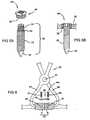
- FIG. 1is a perspective post-operative anterior illustration of a human thorax. Specifically, FIG. 1 illustrates a previously severed sternum coupled by a plate in one possible placement scheme according to the teachings;
- FIG. 2is a perspective view of the plate of FIG. 1 ;
- FIG. 3is a cross-sectional view taken along line 3 - 3 of FIG. 2 ;
- FIG. 4Ais a perspective view of a one-piece, self-tapping fastener used to secure the plate of FIG. 1 to a severed bone portion;
- FIG. 4Bis a perspective view of the fastener of FIG. 4A incorporating a self-drilling tip
- FIG. 4Cis a cross-sectional view of the fastener of FIG. 4A , the fastener seated within a threaded aperture of the plate of FIG. 1 ;
- FIG. 4Dis a cross-sectional view of the fastener of FIG. 4A , the fastener seated within an aperture of the plate of FIG. 1 ;
- FIG. 5Ais an exploded perspective view of a two-piece fastener used to secure the plate of FIG. 1 to a severed bone portion;
- FIG. 5Bis a side view of the fastener of FIG. 5A , the fastener seated within an aperture of the plate of FIG. 1 ;
- FIG. 6is a partially sectioned side view of the plate of FIG. 1 illustrating the cooperation of the plate with the fasteners of FIG. 4 for securing the plate to the previously severed sternum halves, wherein the previously severed sternum halves have been reapproximated using the illustrated surgical forceps;
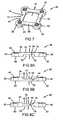
- FIG. 7is a perspective view of a plate according to the present teachings, the plate having four bone securing regions and a bridge region spanning between each bone securing region;
- FIG. 8Ais a side view of the plate of FIG. 7 showing a bridge design in accordance with the principals of the present teachings
- FIG. 8Bis a side view of the plate of FIG. 7 showing a bridge design in accordance with the principals of the present teachings;
- FIG. 8Cis a side view of the plate of FIG. 7 showing a bridge design in accordance with the principals of the present teachings;
- FIG. 9is a perspective view of a plate according to the present teachings, the plate having four bone securing regions and a bridge region spanning between each bone securing region;
- FIG. 10Ais a side view of the plate of FIG. 9 showing a bridge design in accordance with the principals of the present teachings;
- FIG. 10Bis a side view of the plate of FIG. 9 showing a bridge design in accordance with the principals of the present teachings;
- FIG. 10Cis a side view of the plate of FIG. 9 showing a bridge design in accordance with the principals of the present teachings;
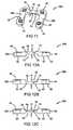
- FIG. 11is a perspective view of a plate according to the present teachings, the plate having two bone securing regions and a bridge region;
- FIG. 12Ais a side view of the plate of FIG. 11 showing a bridge design in accordance with the principals of the present teachings;
- FIG. 12Bis a side view of the plate of FIG. 11 showing a bridge design in accordance with the principals of the present teachings;
- FIG. 12Cis a side view of the plate of FIG. 11 showing a bridge design in accordance with the principals of the present teachings;
- FIG. 13is a perspective view of a plate according to the present teachings, the plate having two bone securing regions and a bridge region;
- FIG. 14Ais a side view of the plate of FIG. 13 showing a bridge design in accordance with the principals of the present teachings;
- FIG. 14Bis a side view of the plate of FIG. 13 showing a bridge design in accordance with the principals of the present teachings;
- FIG. 14Cis a side view of the plate of FIG. 13 showing a bridge design in accordance with the principals of the present teachings;
- FIG. 15is a perspective view of a plate according to the present teachings, the plate having two bone securing regions and a bridge region;
- FIG. 16Ais a side view of the plate of FIG. 15 showing a bridge design in accordance with the principals of the present teachings;
- FIG. 16Bis a side view of the plate of FIG. 15 showing a bridge design in accordance with the principals of the present teachings;
- FIG. 16Cis a side view of the plate of FIG. 15 showing a bridge design in accordance with the principals of the present teachings;
- FIG. 17is a perspective view of the plate of FIG. 7 with a bridge region of the plate engaged by plate cutter, wire cutter, or surgical scissors;
- FIG. 18is a perspective view of the plate of FIG. 7 with a bridge region of the plate engaged by another plate cutter, wire cutter, or pair of surgical scissors;
- FIG. 19is a perspective view of the plate of FIG. 7 with a bridge region of the plate engaged by another plate cutter, wire cutter, or pair of surgical scissors.
- a system constructed in accordance with the present teachingsis generally identified with reference numeral 10.
- the system 10is shown operatively associated within a human body 12 and specifically a human thorax 14.
- a human body 12and specifically a human thorax 14.
- certain aspects of the present teachingshave applicability to other surgical applications.
- the anterior of the thorax 14is formed by a sternum 16, xyphoid 18, manubrium 20, costal cartilage, and ribs 24.
- the clavicle 22is shown connecting the sternum 16 to the scapula and humerus (neither shown).
- the sternum 16, as shownhas previously undergone a medical procedure known as a median sternotomy. As a result of this procedure, the sternum 16 has been severed, thus permitting physician access to the tissues or organs located in thoracic cavity 26. However, the sternum 16 has since been reapproximated with previously severed portions A and B now bound together by the system 10 of the present teachings.
- the system 10 of the present teachingsis shown to include a plate 28.
- the plate 28is shown to include an upper surface 30, a lower surface 32, and a perimeter surface 34.
- the perimeter surface 34may be specifically defined, as seen in FIG. 2 , or may simply be the point at which the upper surface 30 and the lower surface 32 meet.
- the plate 28is divided into varying regions such as at least two bone fixation regions 36 and at least one bridge region 38.
- the bridge region 38joins the bone fixation regions 36 and may be disposed generally flush with either, or both, of the upper or lower surfaces 30, 32 or may be offset from both of the upper and lower surfaces 30, 32, as will be discussed further below.
- Each bone fixation region 36defines at least one aperture 40.
- the apertures 40may be threaded or simply formed as non-threaded through holes.
- the apertures 40may extend symmetrically from the bridge region 38 or may be arranged asymmetrically. Further, the apertures 40 may optionally include a circular or an oval countersink 42 and may be internally threaded, as best shown in FIGS. 2 and 3 .
- the apertures 40are adapted to receive a fastener 44a-c for interconnecting the plate 28 with a severed bone region, such as severed halves A and B of the sternum 16. More specifically, the bridge region 38 spans the fracture while bone fixation regions 36 are fastened to the bone regions on either side of the fracture once the severed halves A and B have been reapproximated.
- the plate 28 described in any of the embodiments of the present teachingsmay be made of a variety of bio-resorbable materials.
- One resorbable material of particular interestis marketed by Biomet, Inc. (Warsaw, Indiana) under the tradename LACTOSORB®.
- LACTOSORB®is an absorbable co-polymer synthesized from all-natural ingredients: 82% L-lactic acid and 18% glycolic acid, and is substantially amorphous (i.e., without crystallinity), meaning that its degradation is uniform, precluding the crystalline release associated with degrading copolymers that have been associated with late inflammatory reactions.
- the LACTOSORB® copolymer ratiopermits the polymer to retain most of its strength for six to eight weeks.
- Such a time periodis appropriate for healing, but not so long as to raise concerns about long-term stress shielding of bone.
- other resorbable materialssuch as PLA, PGA, and others including various polymers, ceramics, etc.
- the plate 28may also be made from a variety of bio-compatible materials. Examples of bio-compatible materials that may be used are the implantable plastics PEEK or PET. In addition to PEEK or PET, implantable surgical metals may also be used. Alloys that may be implanted are, but not limited to, stainless steel, titanium, or cobalt chrome molybdenum. Specifically, commercially pure titanium, listed as grade 1, 2, 3, or 4 or titanium alloy such as titanium 6-aluminum / 4-vanadium may be used.
- the plate 28may be inelastically deformable so as to retain its shape once contoured to cooperate with the shape of the bone regions to be secured.
- a fastener 44ais provided for use with the plate 28.
- the fastener 44ais a one-piece, locking fastener and is designed so as to matingly engage the threaded apertures 40 of bone fixation regions 36.
- the fastener 44ais considered a locking fastener as the engagement between threads 52 on the fastener 44a and the threaded aperture 40 prevents relative movement therebetween.
- preventing relative movement between the plate 28 and the fastener 44ahelps ensure that the plate 28 remains in a desired position relative to the bone halves A, B.
- a second fastener 44bis provided for use with the plate 28.
- the fastener 44bis a one-piece, non-locking fastener and is received by apertures 40b formed through the respective bone fixation regions 36 of the plate 28.
- the fastener 44bis substantially identical to fastener 44a, but is considered a non-locking fastener due to the relationship between the plate 28 and the fastener 44b.
- apertures 40bare simply bores formed through the respective bone fixation regions 36 of the plate 28, and as such, do not include threads, the relationship between the fasteners 44b and the plate 28 is considered "non-locking.” As can be appreciated, such a relationship may provide a cost advantage to the plate 28 as the additional cost associated with forming threads in the apertures 40b is obviated.
- a third fastener 44c of the present teachingsis shown to generally include a main body 46 and a head member 48.
- the main body 46includes an upper shaft portion 50 and a lower shaft portion 52.
- the lower shaft portion 52is externally threaded, fluted, and preferably fitted with a pointed end portion 54 so as to permit self-drilling of the sternum 16 by fastener 44. Insertion of the lower shaft portion 52 into sternum 16 is limited by a flange 56 interdisposed between the upper and lower shaft portions 50 and 52.
- the upper shaft portion 50is also externally threaded and adapted to engage an internally threaded aperture 58 of the head member 48.
- the head member 48is externally threaded for engaging one of the plurality of internally threaded apertures 40 of the plate 28.
- the thread pitches of the upper shaft portion 50, lower shaft portion 52, and the thread pitch of the external threads of the head member 48are common.
- the external threads of the head member 48 and the externally threaded lower shaft portion 52have a common thread lead.
- the externally threaded lower shaft portion 52has a single lead configuration while the external threads of the upper shaft portion 50 and head member 48 have a double lead configuration.
- the use of faster 44cis advantageous because it allows the plate 28 to be removed while the lower portion 52 remains in place in the event that the plate 28 must be removed. This retains the integrity of each hole formed in the bone and eliminates the need to remove and reinsert different fastening devices into the bone each time the plate 28 is removed and re-seated.
- Fasteners 44a-cmay be formed of a suitably rigid biocompatible material. However, if the intent is to insert fasteners 44a-c into the bone for a temporary period of time, it may be formed from a bio-resorbable material. Fasteners 44a-c formed from bio-resorbable materials degrade within the body, thus eliminating the need for subsequent removal of the fasteners 44a-c.
- any of the foregoing fasteners 44a-cmay include a self-tapping feature and/or a self-drilling feature.
- a self-tapping tip 55is used to create a series of threads in the receiving bone, as best shown in FIG. 4A while a self-drilling tip 57 is used to create a bore in the receiving bone, as best shown in FIG. 4B .
- fasteners 44a, 44bmay include either tip 55, 57, that the self-drilling tip 57 may further incorporate a self-tapping feature such that as the generally sharp tip 57 creates a bore in the receiving bone, the tip 57 concurrently cuts a series of threads therein for engagement with the threads 52 of the respective fastener 44a, 44b. Because each fastener 44a-c is inserted through an aperture 40 formed in the bone fixation region 36 of the plate in a similar fashion, fastener 44a will be used herein after when discussing the attachment of the plate 28 to the respective bone halves A, B.
- a reapproximation devicesuch as surgical forceps 60.
- the surgical forceps 60are comprised of two jaws 61, 62 that are interconnected at actuation point 63.
- the jaws 61, 62are able to laterally hook separated bone halves A and B.
- the plate 28is positioned on the bone surfaces to be coupled so that certain apertures 40 may be selectively used as a guide for drilling holes (not specifically shown) in the bone surfaces for receiving the fasteners 44a.
- a first of the fasteners 44ais passed through a selected one of the apertures 40 and rotated so that the externally threaded lower portion 52 is driven into the hole (not shown) in one of the halves A or B of the sternum 16.
- the fastenermay also self-drill and/or self-tap the bone half A, B, depending on the particular tip 55, 57 of the fastener 44a, as previously discussed.
- Additional fasteners 44aare used to interconnect the plate 28 with the sternum 16 in a substantially identical manner. However, it will become appreciated by those skilled in the art that any number of fasteners 44a may be employed depending on a particular application.
- the plate 28After the plate 28 has been secured into place, it may be necessary to remove the plate 28 so as to allow a physician to re-separate the sternum 16 and gain access to either the sternum 16 or the thoracic cavity 26 to provide treatment (e.g., emergency or planned secondary cardiac surgery).
- the fasteners 44aare unthreaded and removed from the apertures 40 of the respective bone fixation regions 36. When the plate 28 is removed, it retains its shape due to the inelastic deformation.
- the separated halves A and B of the sternum 16are again reapproximated using the surgical forceps 60 in the manner described above.
- the halves A and Bare held into place by replacing plate 28.
- the plate 28is replaced by inserting the fasteners 44a through the selective apertures 40 of the bone fixation regions 36 and simultaneously threading the internal threads of the aperture 40 with the external threads 52 of the fastener 44a.
- plate 28ais generally similar to plate 28 and thus a detailed description of plate 28a is not necessary. However, unlike plate 28, plate 28a contains extended bone fixation regions 36a having a plurality of apertures 40. It should be noted that plate 28a also includes bridge regions 38 that connect the respective bone fixation regions 36a.
- plate 28bis generally similar to plate 28 and thus a detailed description of plate 28b is not necessary.
- plate 28bincludes a single bridge region 38 extending between two bone fixation regions 36b. Again, the bridge region 38 extends generally over the bone fracture region while the bone fixation regions 36b are securely attached to respective halves A and B by fasteners 44.
- plate 28cis generally similar to plate 28 and thus a detailed description of plate 28c is not necessary.
- plate 28cincludes a single bridge region 38 extending between two bone fixation regions 36c.
- the bone fixation regions 36care formed at an angle relative to the bridge region 38, as best shown in FIG. 13 .
- the bone fixation regions 36care formed at an angle relative to the bridge region 38 to better fit onto the sternum 16 and to allow for the fixation of transverse fractures. It should be noted that any of the other embodiments of the present teachings may have an orientation between the bone fixation regions 36c and bridge region 38 similar to that of plate 28c.
- Plate 28dis illustrated in FIGS. 15 and 16a-16c and is in accordance with the present teachings. Plate 28d is generally similar to plate 28 and thus a detailed description of plate 28d is not necessary. Plate 28d is different from plate 28 in that plate 28d includes a single bridge region 38 extending generally between two bone fixation regions 36d.
- the bone fixation regions 36dare substantially similar to those of plate 28, except that the bone fixation regions of plate 28d are disposed in an opposite relationship relative to one another. Specifically, a first bone fixation region 36d' runs generally perpendicular to the bridge region 38 while a second bone fixation region 36d" runs generally parallel with the bridge region 38, as best shown in FIG. 15 .
- Bone fixation region 36dincludes a total of three apertures 40 while bone fixation region 36d' includes two apertures 40 for use in attachment to respective bone halves A, B.
- the extra aperture 40 provided on fixation region 36d"allows for an extra fastener to securely fix the fixation region 36d" to a respective bone halve A, B. Therefore, the extra aperture 40 and corresponding fastener 44a serves to restrict fastener pull-through and helps to ensure that the plate 28 remains fixed to the bone halves A, B.
- the bridge region 38may be offset from the bone fixation regions so as to form a recess 70 either between the upper surface 30 and the bridge region 38, between the lower surface 32 and the bridge region 38, or between both surfaces 30, 32 and the bridge region 38, as best shown in FIGS. 8a-c , 10a-c , 12a-c , 14a-c , and 16a-c .
- the bridge region 38could include upper and lower surfaces 76, 78 that are generally planar with the upper and lower surfaces 30, 32 of the bone fixation regions 36, whereby the width W is small enough so as to allow the bridge region 38 to be severed in an emergency, as will be discussed further below.
- the bridge region 38provides each plate 28, 28a, 28b, 28c, and 28d with the requisite strength between the bone halves A, B while the recess 70, or with W of the bridge region 38, concurrently provides a physician or surgeon with the ability to quickly cut the bridge region 38 to quickly remove the plate 28, 28a, 28b, 28c, and 28d. Because each plate 28, 28a, 28b, 28c, and 28d includes a substantially identical bridge region 38, reference will be made to plate 28 when describing the bridge region 38 hereinafter.
- the recess 70may be easily engaged by a cutting device such as surgical scissors 72, wire cutters, plate cutters, or a cautery (only applicable for non-metal fixation) so as to permit the scissors 72, wire cutters, plate cutters, or cautery to sever the bridge region 38, as best shown in FIG. 17 . Consequently, the plate 28 permits a physician or surgeon access to the thoracic cavity 26 by removing the fasteners 44a or by severing the bridge region 38.
- a cutting devicesuch as surgical scissors 72, wire cutters, plate cutters, or a cautery (only applicable for non-metal fixation) so as to permit the scissors 72, wire cutters, plate cutters, or cautery to sever the bridge region 38, as best shown in FIG. 17 . Consequently, the plate 28 permits a physician or surgeon access to the thoracic cavity 26 by removing the fasteners 44a or by severing the bridge region 38.
- the bridge region 38may be tapered at its perimeter surface 74, its upper surface 76, or its lower surface 78 to allow the bridge region 38 to be severed more easily and to provide a smooth surface for added patient comfort. Tapering of the upper surface 76 and the perimeter surface 74 relatively weakens the bridge region 38 and forms the recess 70 generally between upper surface 30 of the bone fixation regions 36 and the upper surface 76 of the bridge region 38, as best shown in FIG. 8a . Tapering of the lower surface 78 results in the formation of the recess 70 generally between the lower surface 32 of the bone fixation regions 36 and the lower surface 78 of the bridge region 38, as best shown in FIG. 8b .
- the recess 70may be formed proximate to both the upper and lower surfaces 76, 78 of the bridge region 38, as best shown in FIG. 8c .
- FIG. 17illustrates plate 28 as having a generally rectangular bridge region 38
- alternate embodimentsmay contain a bridge that is elliptical, oval, or of another cross-section shape that will facilitate engagement of the bridge by a suitable cutting device such as surgical scissors 72 or wire cutters.
- a suitable cutting devicesuch as surgical scissors 72 or wire cutters.
- any of the other embodiments of the present teachingsmay include a bridge region 38 that is cylindrical, elliptical, oval, square, or of another cross-section shape so as to facilitate engagement of the bridge by a suitable cutting device.
- the bridge region 38may include a plurality of varying cross-sectional shapes such as elliptical, oval, or rectangular, the bridge region 38 must be designed so as to accommodate the force requirements with respect to holding the bone halves A, B together while concurrently allowing a physician or surgeon to easily and quickly remove the plate 28 under exigent circumstances.
- the bridge region 38is designed to accommodate both requirements (i.e., strength and severability), by balancing strength requirements with cutability requirements in designing the cross-sectional shape. The latter design feature maintains requisite strength properties while providing for quick and easy removal.
- the relationship between the requisite force required to sever the bridge region 38 and the cross-sectional area of the bridge region 38is substantially linear. Therefore, the larger the cross-sectional area of the bridge region 38, the greater the force required to sever the bridge region 38.
- the cross-sectional area of the bridge region 38is deigned to both accommodate the strength requirements of the system 10 and to optimize the severability of the bridge region 38.
- Optimum bridge severabilitycan be substantially manipulated for a given cross-sectional area, accomplished mainly through manipulation of the aspect ratio of the cross-section of the bridge region 38.
- the aspect ratiois generally defined as the height H of the plate 28 in the cutter 72 divided by the width W of the plate 28 in the cutter 72.
- the height of the bridge region 38is generally defined between upper and lower surfaces 76, 78 of the bridge region 38, while the width is generally measured perpendicular to the upper and lower surfaces 76, 78, as best shown in FIGS. 7 and 8a-c .
- the height of the bridge sectionmay or may not correspond to the height of the plate in the cutter depending on the orientation of the cutter on the bridge section.
- the width of the bridge region 38is generally measured perpendicular to the height of the region 38.
- the width of the bridge region 38is increased, the height of the bridge region 38 is decreased.
- the cutting aspect ratioincreases (H/W)
- an Aspect Ratio Factoris calculated for use in determining a desirable aspect ratio (i.e., height and width) of a bridge region 38.
- the ARFis determined by dividing the cut force in a tested orientation of a bridge portion by an average of the cut forces measured in both directions.
- the aspect ratio of the bridge region 38is defined as the height of the bridge region 38 in a cutter 72 divided by the width of the bridge region 38 in a cutter 72. Therefore, a given bridge region 38 having an aspect ratio of A would have an aspect ratio of 1/A when rotated 90 degrees in the cutter 72.
- ARFCut Force A / Cut Force A + Cut Force 1 / A / 2
- ARF 1 / ACut Force 1 / A / Cut Force A + Cut Force 1 / A / 2
- a force required to cut a square cross-sectionwill be the same regardless of the orientation of the section in the cutter 72 as the width of the section is generally equal to the height.
- the cut force required to sever the bridgeis reduced.
- the natural log of the aspect ratio for a plate having an aspect ratio of 2is 0.69. From a regression of experimental data relating the aspect ratio to the ARF for cross sections made from Grade IV titanium, the natural logarithm of the ARF corresponding to the aspect ratio of 2 is approximately -0.1, which corresponds to an ARF of 0.904. Substituting the ARF value into the above ARF A equation and solving for Cut Force A yields a cut force that is roughly 83% of the load required to cut the same cross-section having an aspect ratio of 1 ⁇ 2.
- the cross-section having an aspect ratio of 1 ⁇ 2has the same cross-sectional area as the section having an aspect ratio of 2, but the section having an aspect ratio of 1 ⁇ 2 is rotated 90 degrees in the cutting tool 72 (such that the above equation is solved for Cut Force 1/A and the aspect ratio is 1/A), and is thus more difficult to cut.
- a bridge region 38 having an aspect ratio of 2is easier to cut than a bridge portion having an aspect ratio of 1 ⁇ 2 (i.e., the bridge region 38 is twice as high as it is wide).
- the bridge region 38has an aspect ratio of either 2 or 1 ⁇ 2, that the bridge region 38 will have an identical cross-sectional area.
- the relationship between the width and heightremains the same.
- a plate 28 having a bridge region 38 measuring 2mm (0.0787 inches) in one direction and 1 mm (0.0394 inches) in the other directionwill yield a cross-sectional area of 2mm 2 (0.0031 square inches).
- the aspect ratioonly changes from 2 to 1 ⁇ 2 when the plate 28 is rotated 90 degrees in the cutting tool 72.
- the aspect ratiois 2 and the plate 28 is easily severed.
- the aspect ratiois 1 ⁇ 2 and the plate 28 requires a higher cut force in order to sever the bridge region 38. Therefore, cut force and aspect ratio are directly related.
- a cut force(i.e., applied to the handles of a cutter) with a particular cutter of 245 N (55.1 Ibf) is generally considered an acceptable force, allowing most surgeons to easily sever a plate 28 using cutting tools 72 commonly found in a crash cart of an emergency room.
- the force required to cut or sever a given bridge region 38 of a plate 28is, in part, dependent on the aspect ratio of the bridge region 38 to be cut.
- the plate 28can be easily cut without reducing the cross-sectional area of the bridge region 38 beyond an acceptable limit by optimizing the aspect ratio of the bridge region's cross-section.
- the first step in designing a plate 28is to ensure that the bridge region 38 is large enough to carry such loads with an appropriate factor of safety. Once an adequate cross-sectional area is determined, the aspect ratio of the section is adjusted to facilitate severability of the section when quick removal of the plate 28 is required.
- the following equations (A-H)are useful in determining the maximum cut height for a given bridge region 38, where h max is the maximum height of the bridge region 38, w is the width of the bridge region 38, and a is the area of the cross-section of the bridge region 38. It should be noted that while the following equations apply for any orientation of the plate 28 in the cutter 72, the use of the bridge width and maximum bridge section height is dependent on relating it to the cutting orientation as shown in FIG. 18 .
- the constants on the left-hand side of the equations A-Hrefer to experimentally determined acceptable cut force values for a given bridge region 38.
- the following equationmay be used to determine an acceptable cut force where CF refers to a Maximum allowable cut force; S1 refers to a slope of a cut force vs. cross-sectional area (determined experimentally); S2 refers to a slope of Ln(ARF) vs. Ln(aspect ratio) (determined experimentally); and C1 refers to a Y-intercept of the cut force vs.
- the cut force (applied to the handle of an instrument by a doctor or physician) requirementsare 283 N (63.7 Ibf), 245 N (55.1 Ibf), 99 N (22.2 Ibf), and 85 N (19.2Ibf), respectively, and generally provide a scale on which a plate designer may choose to set the cut force.
- the 283 N (63.7 Ibf) and 245 N (55.1 Ibf) cut forcerefer to the largest clinically relevant cutter.
- the 99 N (22.2 Ibf) and 85 N (19.2 Ibf) cut forcerefer to the smallest clinically relevant cutter.
- the constants S1, C1 and S2are dependent on the material chosen. The cut force is initially determined for the largest relevant cutter.
- the appropriate relationshipwas experimentally determined to determine the 99 N (22.2 Ibf) and 85 N (19.2 Ibf) on the left hand side of the equation for the small clinically relevant cutter. In essence, this modification to the equation shows that a smaller cutter with the same hand force on the cutter requires a section that can be cut more easily.
- equations A and Eare both set to yield a cut force of 283N (63.7 Ibf) with the area, width, and height as variables.
- equation Agives the relationship between height and width of the bridge section. If the maximum cut height (which may be the same as the width of the bridge section, as shown in FIG. 18 ) is set at 1.27 mm (0.05 inches), the maximum height of the bridge will be determined to be 1.99 mm (0.0784 inches). From the assigned width and determined height, the cross-sectional area can be determined to be 2.53 mm 2 (0.00392 square inches). Any height of the bridge less than 1.99 mm (0.0784 inches) will allow for cutting at a cut force.
- the maximum height of the bridge sectionwould be determined to be 1.44 mm (0.0567 inches).
- the cross-sectional areacan be determined to be 2.87 mm 2 (0.00445 square inches).
- the geometry determined in the second examplehas a cross-sectional area 13.4% larger than the geometry of the first example.
- the mechanical advantagewas determined to be 6.1 to 7.1 depending on hand position, with the plate positioned so that up to 2 mm of cutter extended beyond the plate. In the tested position, the mechanical advantage was determined to be 6.8. From this, the actual force seen by the plate associated with an applied cut force of 63.7 Ibf can be determined in the range of 388 Ibf to 452 Ibf depending on user hand position, and 433 Ibf in the test fixture position. The same determination could be made for the small cutter.
Landscapes
- Health & Medical Sciences (AREA)
- Orthopedic Medicine & Surgery (AREA)
- Surgery (AREA)
- Life Sciences & Earth Sciences (AREA)
- Heart & Thoracic Surgery (AREA)
- Nuclear Medicine, Radiotherapy & Molecular Imaging (AREA)
- Engineering & Computer Science (AREA)
- Biomedical Technology (AREA)
- Neurology (AREA)
- Medical Informatics (AREA)
- Molecular Biology (AREA)
- Animal Behavior & Ethology (AREA)
- General Health & Medical Sciences (AREA)
- Public Health (AREA)
- Veterinary Medicine (AREA)
- Surgical Instruments (AREA)
Description
- The present teachings relate to surgical applications for the repair of bone fractures and deformities. More particularly, the teachings relate to a method and apparatus for securing two severed bone portions in a relatively fixed relationship to each other.
- In various orthopedic surgical procedures, it is necessary to align and secure two severed bone portions in a relatively fixed relationship to each other. For example, it is often necessary to establish such a secured relationship after a bone has been fractured as a result of either natural causes or physician intervention. To ensure that the bone can regenerate in the proper orientation and fuse the fracture, it is important that the bone portions be fixed in the desired position during bone regeneration.
- It is known in the art to provide metal plates for the repair of bone fractures. The plates are generally secured to the fractured bone portions with fasteners such as screws. Among other applications, the plates and fasteners are used to provide rigid stabilization of sternum fractures. The plates conventionally employed for sternum osteosynthesis generally comprise small, generally flat, sections of metal. The sections contain round and perhaps threaded screw holes at various points along their lengths for fastening the sections to bone.
- In one technique for sternum reconstruction, a plate having one or more apertures is positioned proximate to the surface of the sternum so that the plate spans the severed region of the sternum and is held in relative position thereto through a threaded plate/screw interface. The plate is then bent into shape, if necessary, and secured to the sternum using a plurality of fasteners seated within the apertures. Subsequently, the fasteners and plate may be removed to allow surgical access to the sternum (e.g., to treat vital organs within the thoracic cavity). Finally, the same plate or a new plate is again fastened to the sternum through engagement of the fasteners with the sternum.
US 2002/0128654 A1 discloses an elongated plate for coupling severed bone regions comprising at least one bridge region, the at least one bridge region terminating in at least two bone fixation regions. The at least two bone fixation regions each contain at least one aperture for receiving a suitable fastening device for securing the elongated plate to the bone regions to be coupled. The bridge region may be configured so as to be easily severed by a suitable severing device such as surgical scissors. The elongated plate and fastening device may be formed from a bio-compatible or bio-resorbable material.- While known systems utilizing plates and fasteners for aiding the osteosynthesis of severed bone regions have proven to be acceptable for certain applications, such systems are nevertheless susceptible to improvements that may enhance their performance. In this regard, many known systems require time consuming attachment. Additionally, known systems, which necessitate the insertion, removal, and subsequent reinsertion of fasteners into the bone, negatively affect fastener purchase. Furthermore, many known systems do not facilitate cutting of the plate to provide expedited physician access to the area or cavity requiring access through the location spanned by the plate.
- The present teachings relate to an apparatus and method for reapproximating and securing portions of severed bone. Reapproximation of the severed bone portions is carried out using a bone reapproximation device, which is able to laterally hook and reapproximate the separated bone regions. Once reapproximated, the bone regions are coupled using a plate including at least two bone fixation regions and a bridge region disposed between the bone fixation regions. Each bone fixation region contains at least one receptor used to receive a fastener suitable for securing the plate to the bone portions to be coupled. Both the plate and the fastening devices may be bio-resorbable and/or bio-compatible.
- The fasteners may include a main body portion with an upper shaft portion and a lower shaft portion. Once secured to the bone surface due to interaction with the fasteners, the plate may be removed from engagement with the bone surface by removing the head member and subsequently removing the plate from the bone surface. The fastener configuration allows for removal of the plate without requiring removal of the main body portion of the fastener from the bone, thus allowing the main body portion and hole within the bone to be used again in the future to secure the plate to the bone surface. In addition, the plate may alternatively be secured to the bone surface by a one-piece locking, or non-locking, screw such that removal of the plate from the bone requires severing of the plate or removal of each one-piece screw. As can be appreciated, the fastener chosen (i.e., one-piece versus multiple-piece construction) for the particular plate will vary depending on the requirements of the particular application.
- The plate of the present teachings is configured to permit rapid separation of the bone portions previously secured by the plate. The plate may be severed using any suitable cutting device, such as surgical scissors, surgical wire cutters, or surgical plate cutters. Severing of the plate using surgical scissors, wire cutters, or plate cutters is facilitated due to the presence of a bridge region that is specifically configured to allow for such engagement. Optimum bridge severability is accomplished mainly through manipulation of the aspect ratio and area of the cross-section of the bridge region. The aspect ratio of the cross section is generally defined as the height of the bridge region in the cutting device divided by the width of the bridge region in the cutting device. Therefore, the aspect ratio of the cross-section will change depending on the orientation of the cutting device, unless the cross-section of the bridge includes a generally square or round cross-section. Generally speaking, for a cross section of a constant area, as the width of the bridge region in the cutting device is increased, the height of the bridge region is decreased, and the force required to sever the bridge region is reduced. In addition, the bridge region may be raised or tapered so as to ease engagement of the bridge region by surgical wire cutters, surgical plate cutters, or surgical scissors. The bridge region may also be weakened or contain a notch to further aid in severing the bridge region.
- The plate of the present teachings may also have numerous bridge regions and bone fixation regions arranged in a variety of shapes so as to produce a plate with a configuration capable of coupling a large or irregularly shaped region of severed bones, the bones terminating at various different angles to each other. To aid in the coupling of such severed bone regions, the bridge regions and the bone fixation regions may extend at a variety of different angles. Further, the bone fixation regions and the bridge regions may be in differing planes so as to couple severed bone regions that terminate at differing planes to each other.
- Further areas of applicability of the present teachings will become apparent from the detailed description provided hereinafter. It should be understood that the detailed description and specific examples, while indicating the preferred embodiments of the teachings, are intended for purposes of illustration only and are not intended to limit the scope of the teachings.
FIG. 1 is a perspective post-operative anterior illustration of a human thorax. Specifically,FIG. 1 illustrates a previously severed sternum coupled by a plate in one possible placement scheme according to the teachings;FIG. 2 is a perspective view of the plate ofFIG. 1 ;FIG. 3 is a cross-sectional view taken along line 3 - 3 ofFIG. 2 ;FIG. 4A is a perspective view of a one-piece, self-tapping fastener used to secure the plate ofFIG. 1 to a severed bone portion;FIG. 4B is a perspective view of the fastener ofFIG. 4A incorporating a self-drilling tip;FIG. 4C is a cross-sectional view of the fastener ofFIG. 4A , the fastener seated within a threaded aperture of the plate ofFIG. 1 ;FIG. 4D is a cross-sectional view of the fastener ofFIG. 4A , the fastener seated within an aperture of the plate ofFIG. 1 ;FIG. 5A is an exploded perspective view of a two-piece fastener used to secure the plate ofFIG. 1 to a severed bone portion;FIG. 5B is a side view of the fastener ofFIG. 5A , the fastener seated within an aperture of the plate ofFIG. 1 ;FIG. 6 is a partially sectioned side view of the plate ofFIG. 1 illustrating the cooperation of the plate with the fasteners ofFIG. 4 for securing the plate to the previously severed sternum halves, wherein the previously severed sternum halves have been reapproximated using the illustrated surgical forceps;FIG. 7 is a perspective view of a plate according to the present teachings, the plate having four bone securing regions and a bridge region spanning between each bone securing region;FIG. 8A is a side view of the plate ofFIG. 7 showing a bridge design in accordance with the principals of the present teachings;FIG. 8B is a side view of the plate ofFIG. 7 showing a bridge design in accordance with the principals of the present teachings;FIG. 8C is a side view of the plate ofFIG. 7 showing a bridge design in accordance with the principals of the present teachings;FIG. 9 is a perspective view of a plate according to the present teachings, the plate having four bone securing regions and a bridge region spanning between each bone securing region;FIG. 10A is a side view of the plate ofFIG. 9 showing a bridge design in accordance with the principals of the present teachings;FIG. 10B is a side view of the plate ofFIG. 9 showing a bridge design in accordance with the principals of the present teachings;FIG. 10C is a side view of the plate ofFIG. 9 showing a bridge design in accordance with the principals of the present teachings;FIG. 11 is a perspective view of a plate according to the present teachings, the plate having two bone securing regions and a bridge region;FIG. 12A is a side view of the plate ofFIG. 11 showing a bridge design in accordance with the principals of the present teachings;FIG. 12B is a side view of the plate ofFIG. 11 showing a bridge design in accordance with the principals of the present teachings;FIG. 12C is a side view of the plate ofFIG. 11 showing a bridge design in accordance with the principals of the present teachings;FIG. 13 is a perspective view of a plate according to the present teachings, the plate having two bone securing regions and a bridge region;FIG. 14A is a side view of the plate ofFIG. 13 showing a bridge design in accordance with the principals of the present teachings;FIG. 14B is a side view of the plate ofFIG. 13 showing a bridge design in accordance with the principals of the present teachings;FIG. 14C is a side view of the plate ofFIG. 13 showing a bridge design in accordance with the principals of the present teachings;FIG. 15 is a perspective view of a plate according to the present teachings, the plate having two bone securing regions and a bridge region;FIG. 16A is a side view of the plate ofFIG. 15 showing a bridge design in accordance with the principals of the present teachings;FIG. 16B is a side view of the plate ofFIG. 15 showing a bridge design in accordance with the principals of the present teachings;FIG. 16C is a side view of the plate ofFIG. 15 showing a bridge design in accordance with the principals of the present teachings;FIG. 17 is a perspective view of the plate ofFIG. 7 with a bridge region of the plate engaged by plate cutter, wire cutter, or surgical scissors;FIG. 18 is a perspective view of the plate ofFIG. 7 with a bridge region of the plate engaged by another plate cutter, wire cutter, or pair of surgical scissors; andFIG. 19 is a perspective view of the plate ofFIG. 7 with a bridge region of the plate engaged by another plate cutter, wire cutter, or pair of surgical scissors.- The following description is merely exemplary in nature and is in no way intended to limit the teachings, its application, or uses.
- Referring to
FIG. 1 , a system constructed in accordance with the present teachings is generally identified withreference numeral 10. Thesystem 10 is shown operatively associated within ahuman body 12 and specifically ahuman thorax 14. However, it will become apparent to those skilled in the art that certain aspects of the present teachings have applicability to other surgical applications. - The anterior of the
thorax 14 is formed by asternum 16, xyphoid 18,manubrium 20, costal cartilage, andribs 24. In addition, the clavicle 22 is shown connecting thesternum 16 to the scapula and humerus (neither shown). Thesternum 16, as shown, has previously undergone a medical procedure known as a median sternotomy. As a result of this procedure, thesternum 16 has been severed, thus permitting physician access to the tissues or organs located inthoracic cavity 26. However, thesternum 16 has since been reapproximated with previously severed portions A and B now bound together by thesystem 10 of the present teachings. - With continued reference to
FIG. 1 and additional reference toFIGS. 2 through 19 , thesystem 10 of the present teachings is shown to include aplate 28. Theplate 28 is shown to include anupper surface 30, alower surface 32, and aperimeter surface 34. Theperimeter surface 34 may be specifically defined, as seen inFIG. 2 , or may simply be the point at which theupper surface 30 and thelower surface 32 meet. Theplate 28 is divided into varying regions such as at least twobone fixation regions 36 and at least onebridge region 38. - The
bridge region 38 joins thebone fixation regions 36 and may be disposed generally flush with either, or both, of the upper orlower surfaces lower surfaces bone fixation region 36 defines at least oneaperture 40. Theapertures 40 may be threaded or simply formed as non-threaded through holes. Theapertures 40 may extend symmetrically from thebridge region 38 or may be arranged asymmetrically. Further, theapertures 40 may optionally include a circular or anoval countersink 42 and may be internally threaded, as best shown inFIGS. 2 and 3 . Theapertures 40 are adapted to receive afastener 44a-c for interconnecting theplate 28 with a severed bone region, such as severed halves A and B of thesternum 16. More specifically, thebridge region 38 spans the fracture whilebone fixation regions 36 are fastened to the bone regions on either side of the fracture once the severed halves A and B have been reapproximated. - The
plate 28 described in any of the embodiments of the present teachings may be made of a variety of bio-resorbable materials. One resorbable material of particular interest is marketed by Biomet, Inc. (Warsaw, Indiana) under the tradename LACTOSORB®. LACTOSORB® is an absorbable co-polymer synthesized from all-natural ingredients: 82% L-lactic acid and 18% glycolic acid, and is substantially amorphous (i.e., without crystallinity), meaning that its degradation is uniform, precluding the crystalline release associated with degrading copolymers that have been associated with late inflammatory reactions. Furthermore, the LACTOSORB® copolymer ratio permits the polymer to retain most of its strength for six to eight weeks. Such a time period is appropriate for healing, but not so long as to raise concerns about long-term stress shielding of bone. In addition to LACTOSORB®, other resorbable materials may be used such as PLA, PGA, and others including various polymers, ceramics, etc. - The
plate 28 may also be made from a variety of bio-compatible materials. Examples of bio-compatible materials that may be used are the implantable plastics PEEK or PET. In addition to PEEK or PET, implantable surgical metals may also be used. Alloys that may be implanted are, but not limited to, stainless steel, titanium, or cobalt chrome molybdenum. Specifically, commercially pure titanium, listed asgrade 1, 2, 3, or 4 or titanium alloy such as titanium 6-aluminum / 4-vanadium may be used. Theplate 28 may be inelastically deformable so as to retain its shape once contoured to cooperate with the shape of the bone regions to be secured. - With particular reference to
FIGS. 4A-4D , afastener 44a is provided for use with theplate 28. Thefastener 44a is a one-piece, locking fastener and is designed so as to matingly engage the threadedapertures 40 ofbone fixation regions 36. Thefastener 44a is considered a locking fastener as the engagement betweenthreads 52 on thefastener 44a and the threadedaperture 40 prevents relative movement therebetween. As can be appreciated, preventing relative movement between theplate 28 and thefastener 44a helps ensure that theplate 28 remains in a desired position relative to the bone halves A, B. - With particular reference to
FIGS. 4A-4D , asecond fastener 44b is provided for use with theplate 28. Thefastener 44b is a one-piece, non-locking fastener and is received byapertures 40b formed through the respectivebone fixation regions 36 of theplate 28. Thefastener 44b is substantially identical tofastener 44a, but is considered a non-locking fastener due to the relationship between theplate 28 and thefastener 44b. Specifically, becauseapertures 40b are simply bores formed through the respectivebone fixation regions 36 of theplate 28, and as such, do not include threads, the relationship between thefasteners 44b and theplate 28 is considered "non-locking." As can be appreciated, such a relationship may provide a cost advantage to theplate 28 as the additional cost associated with forming threads in theapertures 40b is obviated. - With reference to
FIGS. 5A-5B , athird fastener 44c of the present teachings is shown to generally include amain body 46 and ahead member 48. Themain body 46 includes anupper shaft portion 50 and alower shaft portion 52. Thelower shaft portion 52 is externally threaded, fluted, and preferably fitted with apointed end portion 54 so as to permit self-drilling of thesternum 16 by fastener 44. Insertion of thelower shaft portion 52 intosternum 16 is limited by aflange 56 interdisposed between the upper andlower shaft portions upper shaft portion 50 is also externally threaded and adapted to engage an internally threadedaperture 58 of thehead member 48. Thehead member 48 is externally threaded for engaging one of the plurality of internally threadedapertures 40 of theplate 28. - In one application, the thread pitches of the
upper shaft portion 50,lower shaft portion 52, and the thread pitch of the external threads of thehead member 48 are common. The external threads of thehead member 48 and the externally threadedlower shaft portion 52 have a common thread lead. In the exemplary embodiment illustrated, the externally threadedlower shaft portion 52 has a single lead configuration while the external threads of theupper shaft portion 50 andhead member 48 have a double lead configuration. The use of faster 44c is advantageous because it allows theplate 28 to be removed while thelower portion 52 remains in place in the event that theplate 28 must be removed. This retains the integrity of each hole formed in the bone and eliminates the need to remove and reinsert different fastening devices into the bone each time theplate 28 is removed and re-seated. Fasteners 44a-c may be formed of a suitably rigid biocompatible material. However, if the intent is to insertfasteners 44a-c into the bone for a temporary period of time, it may be formed from a bio-resorbable material.Fasteners 44a-c formed from bio-resorbable materials degrade within the body, thus eliminating the need for subsequent removal of thefasteners 44a-c.- It should be noted that any of the foregoing
fasteners 44a-c may include a self-tapping feature and/or a self-drilling feature. A self-tappingtip 55 is used to create a series of threads in the receiving bone, as best shown inFIG. 4A while a self-drilling tip 57 is used to create a bore in the receiving bone, as best shown inFIG. 4B . It should be understood that while thefasteners tip drilling tip 57 may further incorporate a self-tapping feature such that as the generallysharp tip 57 creates a bore in the receiving bone, thetip 57 concurrently cuts a series of threads therein for engagement with thethreads 52 of therespective fastener fastener 44a-c is inserted through anaperture 40 formed in thebone fixation region 36 of the plate in a similar fashion,fastener 44a will be used herein after when discussing the attachment of theplate 28 to the respective bone halves A, B. - In use, before the
plate 28 may be secured to severed halves A and B ofsternum 16, the severed halves A and B must be reapproximated. Reapproximation of severed sternum halves A and B may be carried out using, as seen inFIG. 6 , a reapproximation device, such assurgical forceps 60. Thesurgical forceps 60 are comprised of twojaws actuation point 63. Thejaws jaws actuation point 63, a physician is able to decrease the distance between thejaws - Once the separated bone halves A and B have been reapproximated, the
plate 28 is positioned on the bone surfaces to be coupled so thatcertain apertures 40 may be selectively used as a guide for drilling holes (not specifically shown) in the bone surfaces for receiving thefasteners 44a. - A first of the
fasteners 44a is passed through a selected one of theapertures 40 and rotated so that the externally threadedlower portion 52 is driven into the hole (not shown) in one of the halves A or B of thesternum 16. For example, as the externally threadedlower portion 52 of thefastener 44a is driven into thesternum 16, theexternal threads 52 simultaneously engage the internally threadedaperture 40 of theplate 28. In addition, the fastener may also self-drill and/or self-tap the bone half A, B, depending on theparticular tip fastener 44a, as previously discussed. Additional fasteners 44a are used to interconnect theplate 28 with thesternum 16 in a substantially identical manner. However, it will become appreciated by those skilled in the art that any number offasteners 44a may be employed depending on a particular application.- After the
plate 28 has been secured into place, it may be necessary to remove theplate 28 so as to allow a physician to re-separate thesternum 16 and gain access to either thesternum 16 or thethoracic cavity 26 to provide treatment (e.g., emergency or planned secondary cardiac surgery). To facilitate removal of theplate 28, thefasteners 44a are unthreaded and removed from theapertures 40 of the respectivebone fixation regions 36. When theplate 28 is removed, it retains its shape due to the inelastic deformation. - When the secondary surgical procedure is complete, the separated halves A and B of the
sternum 16 are again reapproximated using thesurgical forceps 60 in the manner described above. Once the separated halves A and B ofsternum 16 are reapproximated to a desired distance, the halves A and B are held into place by replacingplate 28. Theplate 28 is replaced by inserting thefasteners 44a through theselective apertures 40 of thebone fixation regions 36 and simultaneously threading the internal threads of theaperture 40 with theexternal threads 52 of thefastener 44a. - Referring to
FIGS. 9 and 10a-10c , aplate 28a according to the present teachings is shown.Plate 28a is generally similar toplate 28 and thus a detailed description ofplate 28a is not necessary. However, unlikeplate 28,plate 28a contains extendedbone fixation regions 36a having a plurality ofapertures 40. It should be noted thatplate 28a also includesbridge regions 38 that connect the respectivebone fixation regions 36a. - Referring to
FIGS. 11 and 12a-12c , aplate 28b according to the present teachings is shown.Plate 28b is generally similar toplate 28 and thus a detailed description ofplate 28b is not necessary. However, unlikeplate 28,plate 28b includes asingle bridge region 38 extending between twobone fixation regions 36b. Again, thebridge region 38 extends generally over the bone fracture region while thebone fixation regions 36b are securely attached to respective halves A and B by fasteners 44. - Referring to
FIGS. 13 and 14a-14c , aplate 28c according to the present teachings is shown.Plate 28c is generally similar toplate 28 and thus a detailed description ofplate 28c is not necessary. However, unlikeplate 28,plate 28c includes asingle bridge region 38 extending between twobone fixation regions 36c. Thebone fixation regions 36c are formed at an angle relative to thebridge region 38, as best shown inFIG. 13 . Thebone fixation regions 36c are formed at an angle relative to thebridge region 38 to better fit onto thesternum 16 and to allow for the fixation of transverse fractures. It should be noted that any of the other embodiments of the present teachings may have an orientation between thebone fixation regions 36c andbridge region 38 similar to that ofplate 28c. Plate 28d is illustrated inFIGS. 15 and 16a-16c and is in accordance with the present teachings.Plate 28d is generally similar toplate 28 and thus a detailed description ofplate 28d is not necessary.Plate 28d is different fromplate 28 in thatplate 28d includes asingle bridge region 38 extending generally between twobone fixation regions 36d. Thebone fixation regions 36d are substantially similar to those ofplate 28, except that the bone fixation regions ofplate 28d are disposed in an opposite relationship relative to one another. Specifically, a firstbone fixation region 36d' runs generally perpendicular to thebridge region 38 while a secondbone fixation region 36d" runs generally parallel with thebridge region 38, as best shown inFIG. 15 .Bone fixation region 36d" includes a total of threeapertures 40 whilebone fixation region 36d' includes twoapertures 40 for use in attachment to respective bone halves A, B. Theextra aperture 40 provided onfixation region 36d" allows for an extra fastener to securely fix thefixation region 36d" to a respective bone halve A, B. Therefore, theextra aperture 40 andcorresponding fastener 44a serves to restrict fastener pull-through and helps to ensure that theplate 28 remains fixed to the bone halves A, B.- In each of the foregoing
plates bridge region 38 may be offset from the bone fixation regions so as to form arecess 70 either between theupper surface 30 and thebridge region 38, between thelower surface 32 and thebridge region 38, or between bothsurfaces bridge region 38, as best shown inFIGS. 8a-c ,10a-c ,12a-c ,14a-c , and16a-c . However, it should be noted that thebridge region 38 could include upper andlower surfaces lower surfaces bone fixation regions 36, whereby the width W is small enough so as to allow thebridge region 38 to be severed in an emergency, as will be discussed further below. Thebridge region 38 provides eachplate recess 70, or with W of thebridge region 38, concurrently provides a physician or surgeon with the ability to quickly cut thebridge region 38 to quickly remove theplate plate identical bridge region 38, reference will be made to plate 28 when describing thebridge region 38 hereinafter. - The
recess 70 may be easily engaged by a cutting device such assurgical scissors 72, wire cutters, plate cutters, or a cautery (only applicable for non-metal fixation) so as to permit thescissors 72, wire cutters, plate cutters, or cautery to sever thebridge region 38, as best shown inFIG. 17 . Consequently, theplate 28 permits a physician or surgeon access to thethoracic cavity 26 by removing thefasteners 44a or by severing thebridge region 38. - The
bridge region 38 may be tapered at itsperimeter surface 74, itsupper surface 76, or itslower surface 78 to allow thebridge region 38 to be severed more easily and to provide a smooth surface for added patient comfort. Tapering of theupper surface 76 and theperimeter surface 74 relatively weakens thebridge region 38 and forms therecess 70 generally betweenupper surface 30 of thebone fixation regions 36 and theupper surface 76 of thebridge region 38, as best shown inFIG. 8a . Tapering of thelower surface 78 results in the formation of therecess 70 generally between thelower surface 32 of thebone fixation regions 36 and thelower surface 78 of thebridge region 38, as best shown inFIG. 8b . In addition, therecess 70 may be formed proximate to both the upper andlower surfaces bridge region 38, as best shown inFIG. 8c . It should be noted that whileFIG. 17 illustratesplate 28 as having a generallyrectangular bridge region 38, alternate embodiments may contain a bridge that is elliptical, oval, or of another cross-section shape that will facilitate engagement of the bridge by a suitable cutting device such assurgical scissors 72 or wire cutters. Further, it is envisioned that any of the other embodiments of the present teachings may include abridge region 38 that is cylindrical, elliptical, oval, square, or of another cross-section shape so as to facilitate engagement of the bridge by a suitable cutting device. - While the
bridge region 38 may include a plurality of varying cross-sectional shapes such as elliptical, oval, or rectangular, thebridge region 38 must be designed so as to accommodate the force requirements with respect to holding the bone halves A, B together while concurrently allowing a physician or surgeon to easily and quickly remove theplate 28 under exigent circumstances. Thebridge region 38 is designed to accommodate both requirements (i.e., strength and severability), by balancing strength requirements with cutability requirements in designing the cross-sectional shape. The latter design feature maintains requisite strength properties while providing for quick and easy removal. - The relationship between the requisite force required to sever the
bridge region 38 and the cross-sectional area of thebridge region 38 is substantially linear. Therefore, the larger the cross-sectional area of thebridge region 38, the greater the force required to sever thebridge region 38. The cross-sectional area of thebridge region 38 is deigned to both accommodate the strength requirements of thesystem 10 and to optimize the severability of thebridge region 38. - Optimum bridge severability can be substantially manipulated for a given cross-sectional area, accomplished mainly through manipulation of the aspect ratio of the cross-section of the
bridge region 38. The aspect ratio is generally defined as the height H of theplate 28 in thecutter 72 divided by the width W of theplate 28 in thecutter 72. The height of thebridge region 38 is generally defined between upper andlower surfaces bridge region 38, while the width is generally measured perpendicular to the upper andlower surfaces FIGS. 7 and 8a-c . The height of the bridge section may or may not correspond to the height of the plate in the cutter depending on the orientation of the cutter on the bridge section. In this manner, the width of thebridge region 38 is generally measured perpendicular to the height of theregion 38. Generally speaking, for a constant cross-sectional area or for a given tensile load carried by the bridge section, as the width of thebridge region 38 is increased, the height of thebridge region 38 is decreased. For a given cross-sectional area, as the cutting aspect ratio increases (H/W), the force required to sever the bridge section is reduced. - Because the cut force is directly attributable to the size, shape, and aspect ratio of the cross-section of the
bridge region 38, an Aspect Ratio Factor (ARF) is calculated for use in determining a desirable aspect ratio (i.e., height and width) of abridge region 38. The ARF is determined by dividing the cut force in a tested orientation of a bridge portion by an average of the cut forces measured in both directions. As previously discussed, the aspect ratio of thebridge region 38 is defined as the height of thebridge region 38 in acutter 72 divided by the width of thebridge region 38 in acutter 72. Therefore, a givenbridge region 38 having an aspect ratio of A would have an aspect ratio of 1/A when rotated 90 degrees in thecutter 72. Therefore, the ARF may be determined by the following equations for each aspect ratio:

- For example, a force required to cut a square cross-section will be the same regardless of the orientation of the section in the
cutter 72 as the width of the section is generally equal to the height. For a plate of the same cross-sectional area, but with an aspect ratio of 2 (i.e., thebridge region 38 is twice as wide as it is high), the cut force required to sever the bridge is reduced. - For example, the natural log of the aspect ratio for a plate having an aspect ratio of 2 is 0.69. From a regression of experimental data relating the aspect ratio to the ARF for cross sections made from Grade IV titanium, the natural logarithm of the ARF corresponding to the aspect ratio of 2 is approximately -0.1, which corresponds to an ARF of 0.904. Substituting the ARF value into the above ARFA equation and solving for Cut ForceA yields a cut force that is roughly 83% of the load required to cut the same cross-section having an aspect ratio of ½. The cross-section having an aspect ratio of ½ has the same cross-sectional area as the section having an aspect ratio of 2, but the section having an aspect ratio of ½ is rotated 90 degrees in the cutting tool 72 (such that the above equation is solved for Cut Force1/A and the aspect ratio is 1/A), and is thus more difficult to cut.
- Therefore, a
bridge region 38 having an aspect ratio of 2 (i.e., thebridge region 38 is twice as wide as it is high) is easier to cut than a bridge portion having an aspect ratio of ½ (i.e., thebridge region 38 is twice as high as it is wide). It should be noted that when thebridge region 38 has an aspect ratio of either 2 or ½, that thebridge region 38 will have an identical cross-sectional area. In other words, the relationship between the width and height remains the same. For example, aplate 28 having abridge region 38 measuring 2mm (0.0787 inches) in one direction and 1 mm (0.0394 inches) in the other direction will yield a cross-sectional area of 2mm2 (0.0031 square inches). The aspect ratio only changes from 2 to ½ when theplate 28 is rotated 90 degrees in thecutting tool 72. When thebridge region 38 is cut along the 2mm surface, the aspect ratio is 2 and theplate 28 is easily severed. Conversely, when theplate 28 is cut along the 1 mm section, the aspect ratio is ½ and theplate 28 requires a higher cut force in order to sever thebridge region 38. Therefore, cut force and aspect ratio are directly related. - Based on the inventors' research with a particular cutter, a cut force (i.e., applied to the handles of a cutter) with a particular cutter of 245 N (55.1 Ibf) is generally considered an acceptable force, allowing most surgeons to easily sever a
plate 28 usingcutting tools 72 commonly found in a crash cart of an emergency room. As previously discussed, the force required to cut or sever a givenbridge region 38 of aplate 28 is, in part, dependent on the aspect ratio of thebridge region 38 to be cut. Theplate 28 can be easily cut without reducing the cross-sectional area of thebridge region 38 beyond an acceptable limit by optimizing the aspect ratio of the bridge region's cross-section. - Typically, most devices used in sternal closure procedures are designed to withstand loads ranging from 400N (90 Ibf) to 1200N (270 Ibf). Such loads are generally applied by the patient during breathing, coughing, etc. and must be safely transmitted by one or
more plates 28 to halves A, B viabridge fixation regions 36 and one ormore bridge regions 38. Therefore, the first step in designing aplate 28 is to ensure that thebridge region 38 is large enough to carry such loads with an appropriate factor of safety. Once an adequate cross-sectional area is determined, the aspect ratio of the section is adjusted to facilitate severability of the section when quick removal of theplate 28 is required. - In adjusting the aspect ratio (i.e., height and width) of the
bridge region 38, the following equations (A-H) are useful in determining the maximum cut height for a givenbridge region 38, where hmax is the maximum height of thebridge region 38, w is the width of thebridge region 38, and a is the area of the cross-section of thebridge region 38. It should be noted that while the following equations apply for any orientation of theplate 28 in thecutter 72, the use of the bridge width and maximum bridge section height is dependent on relating it to the cutting orientation as shown inFIG. 18 . More generally, the height could be considered the height of the bridge region in the cutter 72 (and likewise the width of the bridge region in the cutter) and then the specific orientation of cutting drops out:


- The constants on the left-hand side of the equations A-H (i.e., 283 N (63.7 Ibf), 245 N (55.1 Ibf), 99 N (22.2 Ibf), and 85 N (19.2Ibf)) refer to experimentally determined acceptable cut force values for a given
bridge region 38. The following equation may be used to determine an acceptable cut force where CF refers to a Maximum allowable cut force; S1 refers to a slope of a cut force vs. cross-sectional area (determined experimentally); S2 refers to a slope of Ln(ARF) vs. Ln(aspect ratio) (determined experimentally); and C1 refers to a Y-intercept of the cut force vs. cross-sectional area data (determined experimentally):
For the actual cut force to be less than or equal to the maximum allowable cut force given a defined width w, the height H must be less than or equal to Hmax. For a rectangular cross section a = h*w the equation becomes:
- The cut force (applied to the handle of an instrument by a doctor or physician) requirements are 283 N (63.7 Ibf), 245 N (55.1 Ibf), 99 N (22.2 Ibf), and 85 N (19.2Ibf), respectively, and generally provide a scale on which a plate designer may choose to set the cut force. The 283 N (63.7 Ibf) and 245 N (55.1 Ibf) cut force refer to the largest clinically relevant cutter. The 99 N (22.2 Ibf) and 85 N (19.2 Ibf) cut force refer to the smallest clinically relevant cutter. The constants S1, C1 and S2 are dependent on the material chosen. The cut force is initially determined for the largest relevant cutter. However, the following equation can be scaled using the experimentally determined ratio (L1 over L2) of cut force required to sever a given section using a first cutter (L1) versus experimentally determined cut force required to sever the same given section using a second cutter (L2). In this manner, the plate can be severed by other clinically relevant cutters, (e.g., the small cutter) with the scaled equation describing the required cut force is given as:

Using several plate shape sections to determine L1/L2 and regressing the data, the appropriate relationship was experimentally determined to determine the 99 N (22.2 Ibf) and 85 N (19.2 Ibf) on the left hand side of the equation for the small clinically relevant cutter. In essence, this modification to the equation shows that a smaller cutter with the same hand force on the cutter requires a section that can be cut more easily. - While technically, it most correct to multiply S1 and C1 each by the ratio of cut force using the small cutter over cut force using the large cutter, the above equation is equivalent to dividing CF by the quantity (cut force using small cutter over cut force using the large cutter). This is how the equations A and B were scaled to obtain the equations C and D and how the equations E and F were scaled to obtain the equations G and H.
- For example, equations A and E are both set to yield a cut force of 283N (63.7 Ibf) with the area, width, and height as variables. Using this maximum cut force, for a rectangular section and using Grade 4 titanium with the largest clinically relevant cutter, equation A gives the relationship between height and width of the bridge section. If the maximum cut height (which may be the same as the width of the bridge section, as shown in
FIG. 18 ) is set at 1.27 mm (0.05 inches), the maximum height of the bridge will be determined to be 1.99 mm (0.0784 inches). From the assigned width and determined height, the cross-sectional area can be determined to be 2.53 mm2 (0.00392 square inches). Any height of the bridge less than 1.99 mm (0.0784 inches) will allow for cutting at a cut force. - In contrast, using the same equation A based on the same maximum cut force, a rectangular section, and the same cutter, if the height of the plate in the cutter (Corresponding to the width of the bridge section in proposed
Figure 18A ) were set at 1.99 mm (0.0784 inches) (equivalent to the maximum bridge height of the bridge section determined in the prior example), then the maximum height of the bridge section would be determined to be 1.44 mm (0.0567 inches). From the set width and the determined height, the cross-sectional area can be determined to be 2.87 mm2 (0.00445 square inches). For the same cut force, the geometry determined in the second example has a cross-sectional area 13.4% larger than the geometry of the first example. This directly translates into the ability of the bridge section of example 2 to transmit a tensile load 13.4% higher than the bridge section of example 1. In this manner, if a plate must withstand a specified load, and the cross-sectional area needed to withstand the load is known, the aspect ratio can be adjusted using equations A-H to optimize the plate design (i.e., height and width) for both strength and severability. The following table summarizes examples 1 and 2:Example 1 Example 2 Maximum Cut Force 63.7 63.7 Set Width 0.05 0.0784 Determined Height 0.0784 0.0567 Area of Cross Section 0.00392 0.00445 Section Shape 

Based on this calculation, the cut force equation can be rewritten to describe the force applied to the plate (PCF), using the mechanical advantage (MA) of the cutter:
Since PCF = (CF)(MA), it is readily apparent that this equation is equivalent to the previously described relationship. Using the maximum of the range of mechanical advantages measured for the large cutter, equations A, B, E, and F are can be rewritten as A', B', E' and F' as shown below.


By similar means, this principle could be applied to the small cutter tested or to any other relevant cutter to determine the maximum severing force seen by a given plate. This method could also be applied to model the cut force of materials other than Grade 2 or Grade 4 commercially pure titanium using the same characteristic equation and similar testing. - The description of the teachings is merely exemplary in nature and, thus, variations that do not depart from the gist of the teachings are intended to be within the scope of the teachings. Such variations are not to be regarded as a departure from the spirit and scope of the teachings.


Claims (45)
- A device for coupling bone across an osteotomy, comprising:a plate (28) having at least two bone fixation regions (36) and at least one bridge region (38), and bridge region having an aspect ratio defining an optimum height and width of said bridge region to accommodate a load applied across the osteotomy and minimize a cut force required to sever said bridge region, said height and width given by the following equation:wherein "CF" is said cut force in Newtons (N), "a" is a cross-sectional area in square millimeters (mm2) of said bridge region to be severed, "w" is said width, and "hmax" is said height, said equation further including constants "S1," "C1," and "S2" for a given bridge material, constant "S1" being a slope of a range of said cut force versus a range of said cross-sectional area, constant "C1" being a Y-intercept of said curve, and constant "S2" being a slope of Ln(ARF) versus Ln(aspect ratio), wherein "ARF" is an aspect ratio factor that is calculated by determining a first cut force associated with one of said width and said height of said bridge region and determining a second cut force associated with the other of said width and said height, dividing one of said first and second cut forces by the average of said first and second cut forces.

- The device of Claim 1, wherein said at least two bone fixation regions include at least one aperture.
- The device of Claim 2, wherein the apertures are internally threaded.
- The device of Claim 1, further including a fastening device adapted to engage said bone fixation regions to secure said bone fixation regions to one or more portions of bone.
- The device of Claim 4, wherein said fastening device includes an externally threaded lower shaft portion for engaging the bone, an externally threaded upper shaft portion, and a head member that is internally threaded for engaging said upper shaft portion.
- The device of Claim 5, wherein said head member is externally threaded for engaging one of said internally threaded apertures.
- The device of Claim 5, wherein said fastening device includes a flange portion between said lower shaft portion and said upper shaft portion.
- The device of Claim 4, wherein said fastening device is made from a bio-resorbable material.
- The device of Claim 4, wherein said fastening device is made from a bio-compatible material.
- The device of Claim 4, wherein said fastening device includes a pointed end portion.
- The device of Claim 4, wherein said fastening device is self-drilling.
- The device of Claim 1, wherein said bridge region spans the osteotomy.
- The device of Claim 1, wherein said bridge region spans the bone.
- The device of Claim 1, wherein said bridge region is longitudinally disposed at an angle relative to at least one of said bone fixation regions.
- The device of Claim 1, wherein said bridge region is longitudinally disposed at an angle relative to two or more of said bone fixation regions.
- The device of Claim 1, wherein an additional bridge region extends from said bridge region, said additional bridge region terminating in an additional bone fixation region.
- The device of Claim 1, wherein an additional bridge region extends from said bone fixation region, said additional bridge region terminating in an additional bone fixation region.
- The device of Claim 1, wherein said at least two bone fixation regions include an angled portion extending upwardly in a plane of said bridge region.
- The device of Claim 1, wherein said plate includes at least four bridge regions, each of said bridge regions coupled to two or more bone fixation regions.
- The device of Claim 19, wherein said bone fixation regions extend angularly from said bridge region.
- The device of Claim 20, wherein said bone fixation regions have at least two apertures.
- The device of Claim 1, wherein said bone fixation region is coupled on one or more ends to one or more intersecting bridge regions.
- The device of Claim 1, wherein said bone fixation regions are coupled on one or more ends to one or more bridge regions, one of said bridge regions defining a common bridge region.
- The device of Claim 1, wherein said bridge region includes multiple bridge regions terminating in bone fixation regions and disposed in a parallel relationship to each other.
- The device of Claim 1, wherein said bone fixation regions include a portion disposed generally linearly with said upper surface and a stepped portion offset from said upper surface.
- The device of Claim 1, wherein said plate includes bio-resorbable material.
- The device of Claim 1, wherein said plate includes bio-compatible material.
- The device of Claim 27, wherein said biocompatible material is an implant grade metal.
- The device of Claim 28, wherein said implant grade metal is selected from among: commercially pure titanium, titanium alloys, stainless steel and zirconium.
- The device of Claim 1, wherein said height of said bridge region is less than about 0.55 times a width of said bone fixation regions.
- The device of Claim 1, wherein said height of said bridge region is greater than about 1.1 times said width of said bone fixation region.
- The device of Claim 1, wherein a maximum distance between a lower surface and an upper surface of at least one of said bone fixation regions is less than about 3.048 mm.
- The device of Claim 1, wherein said height of said bridge region is less than about 1.397 mm.
- The device of Claim 1, wherein said constant "S1" is equal to 90 N/mm2 and said constant "C1" is equal to 39 N.
- The device of Claim 34, wherein said cut force X is chosen from a group comprising: 238 N, 245 N, 99N, and 85 N.
- The device of Claim 1, wherein said constant "S1" is equal to 84 N/mm2 and said constant "C1" is equal to 16 N.
- The device of Claim 36, wherein said cut force X is chosen from a group comprising: 238 N, 245 N, 99 N, and 85 N.
- The device of Claim 1, wherein a cross-section of said bridge region is generally rectangular.
- The device of Claim 1, wherein said cut force required to sever said bridge region is less than 2011 N.
- The device of Claim 1, wherein said cut force required to sever said bridge region is less than 1722 N.
- The device of Claim 1, wherein said cut force required to sever said bridge region is less than 1490 N.
- The device of Claim 1, wherein said cut force required to sever said bridge region is less than 698 N.
- The device of Claim 1, wherein said cut force required to sever said bridge region is less than 605 N.
- The device of Claim 1, wherein said cut force required to sever said bridge region is less than 516 N.
- The device of claim 1, wherein said range of said cut force versus said range of said cross-sectional area is experimentally determined.

Applications Claiming Priority (1)
| Application Number | Priority Date | Filing Date | Title |
|---|---|---|---|
| US10/980,705US20050065521A1 (en) | 2002-02-22 | 2004-11-03 | Method and apparatus for bone fracture fixation |
Publications (2)
| Publication Number | Publication Date |
|---|---|
| EP1654994A1 EP1654994A1 (en) | 2006-05-10 |
| EP1654994B1true EP1654994B1 (en) | 2008-04-09 |
Family
ID=35589315
Family Applications (1)
| Application Number | Title | Priority Date | Filing Date |
|---|---|---|---|
| EP05022829AExpired - LifetimeEP1654994B1 (en) | 2004-11-03 | 2005-10-19 | Apparatus for bone fracture fixation |
Country Status (5)
| Country | Link |
|---|---|
| US (2) | US20050065521A1 (en) |
| EP (1) | EP1654994B1 (en) |
| JP (1) | JP2006130317A (en) |
| DE (1) | DE602005005918T2 (en) |
| ES (1) | ES2303173T3 (en) |
Cited By (3)
| Publication number | Priority date | Publication date | Assignee | Title |
|---|---|---|---|---|
| US7905909B2 (en) | 2005-09-19 | 2011-03-15 | Depuy Products, Inc. | Bone stabilization system including multi-directional threaded fixation element |
| US8419745B2 (en) | 2010-04-23 | 2013-04-16 | Biomet C.V. | Bone plate bender system |
| US11771481B2 (en) | 2021-03-08 | 2023-10-03 | Zimmer Biomet CMF and Thoracic, LLC | Sternal plates and methods of use |
Families Citing this family (137)
| Publication number | Priority date | Publication date | Assignee | Title |
|---|---|---|---|---|
| US20050065521A1 (en)* | 2002-02-22 | 2005-03-24 | Steger Shon D. | Method and apparatus for bone fracture fixation |
| US20050096657A1 (en)* | 2002-02-26 | 2005-05-05 | Alex Autericque | Osteosynthesis or arthrodesis material comprising a bony plate |
| DE10326690B4 (en)* | 2003-06-04 | 2005-04-28 | Aesculap Ag & Co Kg | Sternum closure |
| US8137382B2 (en) | 2004-11-05 | 2012-03-20 | Biomet Sports Medicine, Llc | Method and apparatus for coupling anatomical features |
| US7749250B2 (en) | 2006-02-03 | 2010-07-06 | Biomet Sports Medicine, Llc | Soft tissue repair assembly and associated method |
| US8361113B2 (en) | 2006-02-03 | 2013-01-29 | Biomet Sports Medicine, Llc | Method and apparatus for coupling soft tissue to a bone |
| US9017381B2 (en) | 2007-04-10 | 2015-04-28 | Biomet Sports Medicine, Llc | Adjustable knotless loops |
| US8298262B2 (en) | 2006-02-03 | 2012-10-30 | Biomet Sports Medicine, Llc | Method for tissue fixation |
| US8118836B2 (en) | 2004-11-05 | 2012-02-21 | Biomet Sports Medicine, Llc | Method and apparatus for coupling soft tissue to a bone |
| US7857830B2 (en)* | 2006-02-03 | 2010-12-28 | Biomet Sports Medicine, Llc | Soft tissue repair and conduit device |
| US7905904B2 (en) | 2006-02-03 | 2011-03-15 | Biomet Sports Medicine, Llc | Soft tissue repair device and associated methods |
| US8840645B2 (en) | 2004-11-05 | 2014-09-23 | Biomet Sports Medicine, Llc | Method and apparatus for coupling soft tissue to a bone |
| US7909851B2 (en) | 2006-02-03 | 2011-03-22 | Biomet Sports Medicine, Llc | Soft tissue repair device and associated methods |
| US8088130B2 (en) | 2006-02-03 | 2012-01-03 | Biomet Sports Medicine, Llc | Method and apparatus for coupling soft tissue to a bone |
| US8128658B2 (en) | 2004-11-05 | 2012-03-06 | Biomet Sports Medicine, Llc | Method and apparatus for coupling soft tissue to bone |
| US8303604B2 (en) | 2004-11-05 | 2012-11-06 | Biomet Sports Medicine, Llc | Soft tissue repair device and method |
| US7658751B2 (en) | 2006-09-29 | 2010-02-09 | Biomet Sports Medicine, Llc | Method for implanting soft tissue |
| US9801708B2 (en) | 2004-11-05 | 2017-10-31 | Biomet Sports Medicine, Llc | Method and apparatus for coupling soft tissue to a bone |
| US8998949B2 (en) | 2004-11-09 | 2015-04-07 | Biomet Sports Medicine, Llc | Soft tissue conduit device |
| US7344538B2 (en) | 2005-03-31 | 2008-03-18 | Depuy Products, Inc. | Mid-foot fixation plate |
| US9119677B2 (en) | 2005-12-09 | 2015-09-01 | DePuy Synthes Products, Inc. | Spinal plate and drill guide |
| US8562645B2 (en) | 2006-09-29 | 2013-10-22 | Biomet Sports Medicine, Llc | Method and apparatus for forming a self-locking adjustable loop |
| US9149267B2 (en) | 2006-02-03 | 2015-10-06 | Biomet Sports Medicine, Llc | Method and apparatus for coupling soft tissue to a bone |
| US9078644B2 (en) | 2006-09-29 | 2015-07-14 | Biomet Sports Medicine, Llc | Fracture fixation device |
| US11259792B2 (en) | 2006-02-03 | 2022-03-01 | Biomet Sports Medicine, Llc | Method and apparatus for coupling anatomical features |
| US8597327B2 (en) | 2006-02-03 | 2013-12-03 | Biomet Manufacturing, Llc | Method and apparatus for sternal closure |
| US8968364B2 (en) | 2006-02-03 | 2015-03-03 | Biomet Sports Medicine, Llc | Method and apparatus for fixation of an ACL graft |
| US9468433B2 (en) | 2006-02-03 | 2016-10-18 | Biomet Sports Medicine, Llc | Method and apparatus for forming a self-locking adjustable loop |
| US9538998B2 (en) | 2006-02-03 | 2017-01-10 | Biomet Sports Medicine, Llc | Method and apparatus for fracture fixation |
| US8801783B2 (en) | 2006-09-29 | 2014-08-12 | Biomet Sports Medicine, Llc | Prosthetic ligament system for knee joint |
| US8251998B2 (en)* | 2006-08-16 | 2012-08-28 | Biomet Sports Medicine, Llc | Chondral defect repair |
| US10517587B2 (en) | 2006-02-03 | 2019-12-31 | Biomet Sports Medicine, Llc | Method and apparatus for forming a self-locking adjustable loop |
| US8652172B2 (en) | 2006-02-03 | 2014-02-18 | Biomet Sports Medicine, Llc | Flexible anchors for tissue fixation |
| US11311287B2 (en) | 2006-02-03 | 2022-04-26 | Biomet Sports Medicine, Llc | Method for tissue fixation |
| US8562647B2 (en) | 2006-09-29 | 2013-10-22 | Biomet Sports Medicine, Llc | Method and apparatus for securing soft tissue to bone |
| US8771352B2 (en) | 2011-05-17 | 2014-07-08 | Biomet Sports Medicine, Llc | Method and apparatus for tibial fixation of an ACL graft |
| US8506597B2 (en) | 2011-10-25 | 2013-08-13 | Biomet Sports Medicine, Llc | Method and apparatus for interosseous membrane reconstruction |
| US8652171B2 (en) | 2006-02-03 | 2014-02-18 | Biomet Sports Medicine, Llc | Method and apparatus for soft tissue fixation |
| US9271713B2 (en) | 2006-02-03 | 2016-03-01 | Biomet Sports Medicine, Llc | Method and apparatus for tensioning a suture |
| US8574235B2 (en) | 2006-02-03 | 2013-11-05 | Biomet Sports Medicine, Llc | Method for trochanteric reattachment |
| US8246663B2 (en)* | 2006-04-10 | 2012-08-21 | Scott Lovald | Osteosynthesis plate, method of customizing same, and method for installing same |
| DE102006021025B3 (en)* | 2006-04-28 | 2008-01-03 | Aesculap Ag & Co. Kg | Surgical fixation device for two bone parts |
| US10085780B2 (en) | 2006-05-26 | 2018-10-02 | Mark Richard Cunliffe | Bone fixation device |
| US20120029576A1 (en)* | 2006-05-26 | 2012-02-02 | Mark Richard Cunliffe | Bone Fixation Device |
| DE102006046424B3 (en)* | 2006-09-22 | 2007-11-08 | Aesculap Ag & Co. Kg | Sternum closure comprises pairs of plates with L-shaped cross-section positioned on inner surface of sternum and plates with C-shaped cross-section on its outer surface, plates being fastened together by pins passing through them |
| DE102006046428A1 (en)* | 2006-09-22 | 2008-04-03 | Aesculap Ag & Co. Kg | sternal closure |
| US8672969B2 (en) | 2006-09-29 | 2014-03-18 | Biomet Sports Medicine, Llc | Fracture fixation device |
| US9918826B2 (en) | 2006-09-29 | 2018-03-20 | Biomet Sports Medicine, Llc | Scaffold for spring ligament repair |
| US11259794B2 (en) | 2006-09-29 | 2022-03-01 | Biomet Sports Medicine, Llc | Method for implanting soft tissue |
| US8500818B2 (en) | 2006-09-29 | 2013-08-06 | Biomet Manufacturing, Llc | Knee prosthesis assembly with ligament link |
| DE102006055870A1 (en)* | 2006-11-23 | 2008-06-05 | Joachim Maass | Device for blockage of movement of bone parts in opposite directions for treatment of bone injuries, has one or multiple movement barriers arranged along dividing line in such a manner that they simultaneously block both parts of bone |
| EP2397094B1 (en) | 2007-11-02 | 2013-06-26 | Biomet C.V. | Elbow fracture fixation system |
| US8317842B2 (en) | 2007-11-30 | 2012-11-27 | Biomet C.V. | Distal tibia plating system |
| US8257407B2 (en)* | 2008-04-23 | 2012-09-04 | Aryan Henry E | Bone plate system and method |
| US8337533B2 (en)* | 2008-06-20 | 2012-12-25 | Osteomed Llc | Locking plate benders |
| ATE536563T1 (en)* | 2008-08-18 | 2011-12-15 | Qioptiq Photonics Gmbh & Co Kg | METHOD FOR PRODUCING A LENS |
| US12245759B2 (en) | 2008-08-22 | 2025-03-11 | Biomet Sports Medicine, Llc | Method and apparatus for coupling soft tissue to bone |
| US12419632B2 (en) | 2008-08-22 | 2025-09-23 | Biomet Sports Medicine, Llc | Method and apparatus for coupling anatomical features |
| US8828063B2 (en) | 2008-11-19 | 2014-09-09 | Amei Technologies, Inc. | Fixation plate for use in the Lapidus approach |
| FR2942125B1 (en)* | 2009-02-17 | 2012-02-17 | Obl | CUSTOM-MADE ASSEMBLY OF AT LEAST TWO OSTEOSYNTHESIS PLATES, THEMSELVES PREPARED TO MEASURE, AND METHOD FOR PLACING THE SAME |
| US8246664B2 (en) | 2009-02-24 | 2012-08-21 | Osteomed Llc | Multiple bone fusion plate |
| US8574270B2 (en) | 2009-03-13 | 2013-11-05 | Spinal Simplicity Llc | Bone plate assembly with bone screw retention features |
| JP5548710B2 (en) | 2009-03-13 | 2014-07-16 | スパイナル シンプリシティ エルエルシー | Dynamic spine plate system |
| US20100256687A1 (en)* | 2009-04-01 | 2010-10-07 | Merete Medical Gmbh | Fixation Device and Method of Use for a Ludloff Osteotomy Procedure |
| DE102009016394B4 (en) | 2009-04-07 | 2016-02-11 | Merete Medical Gmbh | Device for stable-angle fixation and compression of a fracture site or osteotomy on a bone |
| US9566098B2 (en) | 2009-04-23 | 2017-02-14 | University Of Massachusetts | Bone fixture assembly |
| WO2010124230A1 (en) | 2009-04-23 | 2010-10-28 | University Of Massachusetts | Bone fixture assembly |
| US8529608B2 (en) | 2009-04-28 | 2013-09-10 | Osteomed Llc | Bone plate with a transfixation screw hole |
| WO2010132252A1 (en)* | 2009-05-12 | 2010-11-18 | Synthes Usa, Llc | Readjustable locking plate hole |
| US8343227B2 (en) | 2009-05-28 | 2013-01-01 | Biomet Manufacturing Corp. | Knee prosthesis assembly with ligament link |
| US12096928B2 (en) | 2009-05-29 | 2024-09-24 | Biomet Sports Medicine, Llc | Method and apparatus for coupling soft tissue to a bone |
| US8668697B2 (en)* | 2009-10-07 | 2014-03-11 | Abyrx, Inc. | Methods and devices for sternal closure |
| US8337497B2 (en)* | 2009-10-07 | 2012-12-25 | Doctors Research Group, Inc. | Methods for sternal closure |
| EP2515779B1 (en) | 2009-12-22 | 2016-03-02 | Merete Medical GmbH | Bone plate system for osteosynthesis |
| ES2525129T3 (en)* | 2009-12-30 | 2014-12-17 | Medartis Ag | Osteosynthesis plate for the treatment of fractures near a joint or osteotomies |
| FR2956971B1 (en) | 2010-03-08 | 2012-03-02 | Memometal Technologies | PLATE OSTEOSYNTHESIS SYSTEM |
| FR2956972B1 (en) | 2010-03-08 | 2012-12-28 | Memometal Technologies | ARTICULATED OSTEOSYNTHESIS PLATE |
| JP2011217768A (en)* | 2010-04-02 | 2011-11-04 | Hoya Corp | Fixing member, and fixing member set |
| US8435270B2 (en) | 2010-04-29 | 2013-05-07 | Synthes Usa, Llc | Orthognathic implant and methods of use |
| US9066733B2 (en) | 2010-04-29 | 2015-06-30 | DePuy Synthes Products, Inc. | Orthognathic implant and methods of use |
| WO2011136775A1 (en)* | 2010-04-29 | 2011-11-03 | Synthes Usa, Llc | Orthognatic implant and methods of use |
| US9592084B2 (en)* | 2010-08-27 | 2017-03-14 | William P. Grant | Foot beam insert |
| US20120245693A1 (en)* | 2011-03-25 | 2012-09-27 | Josef Gorek | Spinal fixation device |
| US12329373B2 (en) | 2011-05-02 | 2025-06-17 | Biomet Sports Medicine, Llc | Method and apparatus for soft tissue fixation |
| WO2013003719A1 (en) | 2011-06-29 | 2013-01-03 | Biomet Microfixation, Llc | Locking mechanism to secure ends of an implantable fabric |
| DE202011051165U1 (en) | 2011-08-31 | 2011-11-14 | Merete Medical Gmbh | Anatomically adapted, plantar bone plate and bone plate system |
| US11123117B1 (en) | 2011-11-01 | 2021-09-21 | Nuvasive, Inc. | Surgical fixation system and related methods |
| US9357991B2 (en) | 2011-11-03 | 2016-06-07 | Biomet Sports Medicine, Llc | Method and apparatus for stitching tendons |
| US9314241B2 (en) | 2011-11-10 | 2016-04-19 | Biomet Sports Medicine, Llc | Apparatus for coupling soft tissue to a bone |
| US9381013B2 (en) | 2011-11-10 | 2016-07-05 | Biomet Sports Medicine, Llc | Method for coupling soft tissue to a bone |
| US9370350B2 (en) | 2011-11-10 | 2016-06-21 | Biomet Sports Medicine, Llc | Apparatus for coupling soft tissue to a bone |
| US9265543B2 (en) | 2011-12-27 | 2016-02-23 | Pioneer Surgical Technology, Inc. | Bone plate system and method |
| US9795423B2 (en)* | 2012-01-23 | 2017-10-24 | DePuy Synthes Products, Inc. | Device and method for normalizing implant strain readings to assess bone healing |
| DE102012103894B4 (en) | 2012-05-03 | 2016-10-27 | Merete Medical Gmbh | Bone plate system for osteosynthesis |
| US8974504B2 (en) | 2012-05-10 | 2015-03-10 | Spinal Simplicity Llc | Dynamic bone fracture plates |
| US9207094B2 (en)* | 2012-06-10 | 2015-12-08 | Apple Inc. | Road height generation for a road network |
| US9208601B2 (en) | 2012-06-10 | 2015-12-08 | Apple Inc. | Computing plausible road surfaces in 3D from 2D geometry |
| ES2534058T3 (en)* | 2012-09-18 | 2015-04-17 | Karl Leibinger Medizintechnik Gmbh & Co. Kg | Sternum closure in the form of a sternal plate with an integral sectioning point component |
| US9561064B2 (en) | 2012-11-21 | 2017-02-07 | Pioneer Surgical Technology, Inc. | Bone plate system and method |
| US10765465B2 (en) | 2012-11-21 | 2020-09-08 | A&E Advanced Closure Systems, Llc | Tensioning instrument |
| US9757119B2 (en) | 2013-03-08 | 2017-09-12 | Biomet Sports Medicine, Llc | Visual aid for identifying suture limbs arthroscopically |
| US9918827B2 (en) | 2013-03-14 | 2018-03-20 | Biomet Sports Medicine, Llc | Scaffold for spring ligament repair |
| US9820755B2 (en)* | 2013-03-15 | 2017-11-21 | Zimmer Biomet CMF and Thoracic, LLC | Sternal closure cerclage, plate implant and instrumentation |
| WO2014144479A1 (en) | 2013-03-15 | 2014-09-18 | Biomet Microfixation, Llc | Sternal closure cerclage, plate implant and instrumentation |
| US9545276B2 (en) | 2013-03-15 | 2017-01-17 | Aristotech Industries Gmbh | Fixation device and method of use for a lapidus-type plantar hallux valgus procedure |
| US10010359B2 (en) | 2013-03-15 | 2018-07-03 | Zimmer Biomet CMF and Thoracic, LLC | Sternal closure cerclage, plate implant and instrumentation |
| US10433889B2 (en) | 2013-07-11 | 2019-10-08 | Stryker European Holdings I, Llc | Fixation assembly with a flexible elongated member for securing parts of a sternum |
| US9999454B2 (en) | 2013-12-05 | 2018-06-19 | A&E Advanced Closure Systems, Llc | Bone plate system and method |
| US10136886B2 (en) | 2013-12-20 | 2018-11-27 | Biomet Sports Medicine, Llc | Knotless soft tissue devices and techniques |
| USD745162S1 (en) | 2014-01-27 | 2015-12-08 | Merete Medical Gmbh | Bone plate |
| JP6585071B2 (en)* | 2014-03-14 | 2019-10-02 | ジンマー バイオメット シーエムエフ アンド ソラシック,リミティド ライアビリティ カンパニー | Closure system |
| US10314635B2 (en) | 2014-05-28 | 2019-06-11 | A&E Advanced Closure Systems, Llc | Tensioning instruments |
| US9615822B2 (en) | 2014-05-30 | 2017-04-11 | Biomet Sports Medicine, Llc | Insertion tools and method for soft anchor |
| US9700291B2 (en) | 2014-06-03 | 2017-07-11 | Biomet Sports Medicine, Llc | Capsule retractor |
| US10039543B2 (en) | 2014-08-22 | 2018-08-07 | Biomet Sports Medicine, Llc | Non-sliding soft anchor |
| US9827026B1 (en)* | 2014-09-30 | 2017-11-28 | Allscripts Software, Llc | Nuss procedure aid |
| US10448981B2 (en) | 2015-01-08 | 2019-10-22 | Neutin Orthopedics, LLC | Fixed bone plate for rotational and translational first metatarsal osteotomy procedures |
| EP3042622B1 (en) | 2015-01-09 | 2018-05-09 | Stryker European Holdings I, LLC | Implant for bone fixation |
| US9955980B2 (en) | 2015-02-24 | 2018-05-01 | Biomet Sports Medicine, Llc | Anatomic soft tissue repair |
| US9974534B2 (en) | 2015-03-31 | 2018-05-22 | Biomet Sports Medicine, Llc | Suture anchor with soft anchor of electrospun fibers |
| US9877839B2 (en) | 2015-08-25 | 2018-01-30 | Wright Medical Technology, Inc. | Modular talar fixation method and system |
| EP3405131B1 (en) | 2016-01-22 | 2023-07-19 | A&E Advanced Closure Systems, LLC | Bone plate having a connector and a connector for a surgical loop |
| WO2017156221A1 (en)* | 2016-03-11 | 2017-09-14 | Jace Medical, Llc | Orthopaedic fixation devices, systems and methods |
| CN105943150A (en)* | 2016-06-06 | 2016-09-21 | 广州雄俊智能科技有限公司 | Personalized bone fracture plate and manufacturing method thereof |
| CN106108999A (en)* | 2016-06-12 | 2016-11-16 | 谭海涛 | A kind of personalized blade plate and manufacture method thereof |
| CA3031931C (en) | 2016-07-29 | 2022-10-04 | A&E Advanced Closure Systems, Llc | Surgical cable tensioner |
| EP3320868B1 (en) | 2016-11-11 | 2019-05-01 | Stryker European Holdings I, LLC | Implant for bone fixation |
| IT201700006369A1 (en)* | 2017-01-20 | 2018-07-20 | Orthofix Srl | Internal plate fixation device |
| US10709485B2 (en) | 2017-06-30 | 2020-07-14 | Brian K. P. Vickaryous | Neutralization plate and related methods |
| JP6980970B2 (en) | 2018-01-26 | 2021-12-15 | メイラ株式会社 | Bone treatment tools, bone screws and bone plates |
| CN109480981B (en)* | 2018-12-25 | 2021-06-15 | 朱成伟 | A cranial fracture repair device suitable for clinical neurosurgery |
| US11490937B2 (en)* | 2019-12-13 | 2022-11-08 | Jace Medical, Llc | Bone closure assembly |
| US11957394B2 (en) | 2020-02-27 | 2024-04-16 | J.M. Longyear Manufacturing, Llc | Screw caddy |
| DE102020134246A1 (en)* | 2020-12-18 | 2022-06-23 | Karl Leibinger Medizintechnik Gmbh & Co. Kg | Fingerless Maxillary Reduction Implant |
| US12226134B2 (en) | 2021-02-09 | 2025-02-18 | Zimmer Biomet CMF and Thoracic, LLC | Rigid sternal fixation |
| DE102021202393A1 (en) | 2021-03-11 | 2022-09-15 | Karl Leibinger Medizintechnik Gmbh & Co. Kg | OPTIMIZED IMPLANT SYSTEM |
| US11819399B2 (en)* | 2021-07-06 | 2023-11-21 | Wright Medical Technology, Inc. | Systems and methods of plate trial packaging |
Family Cites Families (58)
| Publication number | Priority date | Publication date | Assignee | Title |
|---|---|---|---|---|
| US1105105A (en)* | 1912-02-10 | 1914-07-28 | William O'n Sherman | Surgical appliance. |
| US2489870A (en)* | 1946-03-02 | 1949-11-29 | Dzus William | Bone fastening device |
| US2494229A (en)* | 1946-07-08 | 1950-01-10 | John G Collison | Bone surgery |
| US2631584A (en)* | 1948-07-22 | 1953-03-17 | Alfred T Purificato | Fracture securing instrument |
| DE867422C (en) | 1951-11-13 | 1953-02-16 | Alfred Dr Med Abel | Screw-on bone plate for the healing of broken bones |
| US3488779A (en)* | 1967-09-27 | 1970-01-13 | Robert W Christensen | Orthopedic prosthetic appliances for attachment to bone |
| CH613858A5 (en)* | 1977-04-22 | 1979-10-31 | Straumann Inst Ag | |
| CH648197A5 (en)* | 1980-05-28 | 1985-03-15 | Synthes Ag | IMPLANT AND SCREW FASTENING ON ITS BONE. |
| IT1132843B (en)* | 1980-09-15 | 1986-07-09 | Cise Spa | PLATE FOR JOINTS OF SEPARATE BONE PORTIONS FROM FRACTURE |
| FR2556583B1 (en)* | 1983-12-19 | 1986-04-18 | Inst Nat Sante Rech Med | OSTEOSYNTHESIS PLATES FOR BONE DEROTATION, ESPECIALLY FEMORAL DEROTATION |
| US4683878A (en)* | 1985-04-29 | 1987-08-04 | Kirschner Medical Corporation | Osteosynthetic fixation plate |
| DE3601715A1 (en)* | 1986-01-22 | 1987-07-23 | Heinl Thomas | SURGICAL INSTRUMENT SET FOR CONNECTING BONE FRAGMENTS |
| US4708132A (en)* | 1986-01-24 | 1987-11-24 | Pfizer-Hospital Products Group, Inc. | Fixation device for a ligament or tendon prosthesis |
| US4966599A (en)* | 1987-04-07 | 1990-10-30 | Pollock Richard A | Anatomical precontoured plating, instruments and methods |
| DE8706912U1 (en)* | 1987-05-14 | 1987-08-27 | Howmedica GmbH, 2314 Schönkirchen | Small bone plate and screws, particularly for the treatment of fractures of the skull and facial skeleton or similar. |
| US5151103A (en)* | 1987-11-03 | 1992-09-29 | Synthes (U.S.A.) | Point contact bone compression plate |
| US4905679A (en)* | 1988-02-22 | 1990-03-06 | M P Operation, Inc. | Bone fracture reduction device and method of internal fixation of bone fractures |
| US4973332A (en)* | 1988-09-12 | 1990-11-27 | Hospital For Joint Diseases | Attachment for femur sliding screw plate |
| DE3831657A1 (en)* | 1988-09-17 | 1990-03-22 | Boehringer Ingelheim Kg | DEVICE FOR THE OSTEOSYNTHESIS AND METHOD FOR THE PRODUCTION THEREOF |
| SE462137B (en)* | 1988-10-18 | 1990-05-14 | Freddy Rafael Astudillo Ley | DEVICE FOR CONNECTING AN OPENING IN STERNUM |
| US5474553A (en)* | 1989-04-18 | 1995-12-12 | Rainer Baumgart | System for setting tubular bone fractures |
| US4959065A (en)* | 1989-07-14 | 1990-09-25 | Techmedica, Inc. | Bone plate with positioning member |
| FR2651992B1 (en)* | 1989-09-18 | 1991-12-13 | Sofamor | IMPLANT FOR ANTERIOR DORSO-LUMBAR SPINE OSTEOSYNTHESIS FOR CORRECTION OF CYPHOSIS. |
| DE3942326A1 (en)* | 1989-12-21 | 1991-06-27 | Haerle Anton | SCREW AS AN OSTEOSYNTHESIS TOOL |
| DE9017101U1 (en)* | 1990-12-19 | 1991-04-11 | Gerhard Hug Gmbh, 7801 Umkirch | Bone screw |
| CS277533B6 (en)* | 1990-12-29 | 1993-03-17 | Krajicek Milan | Fixed osteaosynthesis appliance |
| US5129899A (en)* | 1991-03-27 | 1992-07-14 | Smith & Nephew Richards Inc. | Bone fixation apparatus |
| DE59203295D1 (en)* | 1991-06-25 | 1995-09-21 | Synthes Ag | FASTENING ELEMENT. |
| US5180381A (en)* | 1991-09-24 | 1993-01-19 | Aust Gilbert M | Anterior lumbar/cervical bicortical compression plate |
| CH686339A5 (en)* | 1991-12-10 | 1996-03-15 | Synthes Ag | Nut for the plate fixation. |
| GB2265429A (en)* | 1992-03-18 | 1993-09-29 | Yang Tai Her | "i mprovements in screws or nuts" |
| US5290281A (en)* | 1992-06-15 | 1994-03-01 | Medicon Eg | Surgical system |
| US5336224A (en)* | 1992-11-30 | 1994-08-09 | Ace Medical Company | Bone fixation plate |
| US5601554A (en)* | 1993-03-04 | 1997-02-11 | Advanced Spine Fixation Systems, Inc. | Branch connector for spinal fixation systems |
| WO1995005782A1 (en)* | 1993-08-27 | 1995-03-02 | Robin Peter Brown | Apparatus and method for surgically securing bone parts |
| FR2709412B1 (en)* | 1993-09-01 | 1995-11-24 | Tornier Sa | Screw for lumbo-sacral fixator. |
| US5468242A (en)* | 1993-11-19 | 1995-11-21 | Leibinger Gmbh | Form-fitting mesh implant |
| DE4339804A1 (en)* | 1993-11-23 | 1995-06-01 | Haerle Anton | Power transmission link for osteosynthesis work |
| US5487743A (en)* | 1994-02-15 | 1996-01-30 | Sofamore, S.N.C. | Anterior dorso-lumbar spinal osteosynthesis instrumentation for the correction of kyphosis |
| US5601553A (en)* | 1994-10-03 | 1997-02-11 | Synthes (U.S.A.) | Locking plate and bone screw |
| US5474551A (en)* | 1994-11-18 | 1995-12-12 | Smith & Nephew Richards, Inc. | Universal coupler for spinal fixation |
| CA2189744C (en)* | 1995-03-27 | 2003-09-16 | Gilbert Talos | Bone plate |
| US5569247A (en)* | 1995-03-27 | 1996-10-29 | Smith & Nephew Richards, Inc. | Enhanced variable angle bone bolt |
| US5520690A (en)* | 1995-04-13 | 1996-05-28 | Errico; Joseph P. | Anterior spinal polyaxial locking screw plate assembly |
| US5607428A (en)* | 1995-05-01 | 1997-03-04 | Lin; Kwan C. | Orthopedic fixation device having a double-threaded screw |
| US6488685B1 (en)* | 1995-06-26 | 2002-12-03 | Easton L. Manderson | Extramedullary rod fixateur for bones |
| DE19534831C2 (en)* | 1995-09-20 | 1998-10-29 | Medartis Ag | Cutting pliers for cutting implant plates |
| US5676667A (en)* | 1995-12-08 | 1997-10-14 | Hausman; Michael | Bone fixation apparatus and method |
| IT1287564B1 (en)* | 1996-09-04 | 1998-08-06 | Maurizio Carta | PROCEDURE FOR THE PRODUCTION OF VARIABLE THICKNESS PLATES FOR OSTEOSYNTHESIS. |
| US5752958A (en)* | 1997-04-02 | 1998-05-19 | Wellisz; Tadeusz Z. | Bone fixation plate |
| GB2324470A (en)* | 1997-04-24 | 1998-10-28 | Customflex Limited | Prosthetic implants |
| US6007538A (en)* | 1997-07-25 | 1999-12-28 | Duke University | Sternal closure device |
| US6129728A (en)* | 1998-02-18 | 2000-10-10 | Walter Lorenz Surgical, Inc. | Method and apparatus for mandibular osteosynthesis |
| US6325803B1 (en)* | 1998-02-18 | 2001-12-04 | Walter Lorenz Surgical, Inc. | Method and apparatus for mandibular osteosynthesis |
| US7052499B2 (en)* | 1998-02-18 | 2006-05-30 | Walter Lorenz Surgical, Inc. | Method and apparatus for bone fracture fixation |
| DE29909025U1 (en)* | 1999-05-25 | 1999-11-04 | Lipat Consulting Ag, Basel | Osteosynthetic bone plate |
| US6565570B2 (en)* | 2001-03-14 | 2003-05-20 | Electro-Biology, Inc. | Bone plate and retractor assembly |
| US20050065521A1 (en)* | 2002-02-22 | 2005-03-24 | Steger Shon D. | Method and apparatus for bone fracture fixation |
- 2004
- 2004-11-03USUS10/980,705patent/US20050065521A1/ennot_activeAbandoned
- 2005
- 2005-10-19DEDE602005005918Tpatent/DE602005005918T2/enactiveActive
- 2005-10-19ESES05022829Tpatent/ES2303173T3/ennot_activeExpired - Lifetime
- 2005-10-19EPEP05022829Apatent/EP1654994B1/ennot_activeExpired - Lifetime
- 2005-11-02JPJP2005319509Apatent/JP2006130317A/enactivePending
- 2010
- 2010-03-25USUS12/732,009patent/US8460345B2/ennot_activeExpired - Fee Related
Cited By (3)
| Publication number | Priority date | Publication date | Assignee | Title |
|---|---|---|---|---|
| US7905909B2 (en) | 2005-09-19 | 2011-03-15 | Depuy Products, Inc. | Bone stabilization system including multi-directional threaded fixation element |
| US8419745B2 (en) | 2010-04-23 | 2013-04-16 | Biomet C.V. | Bone plate bender system |
| US11771481B2 (en) | 2021-03-08 | 2023-10-03 | Zimmer Biomet CMF and Thoracic, LLC | Sternal plates and methods of use |
Also Published As
| Publication number | Publication date |
|---|---|
| EP1654994A1 (en) | 2006-05-10 |
| US20050065521A1 (en) | 2005-03-24 |
| ES2303173T3 (en) | 2008-08-01 |
| DE602005005918T2 (en) | 2009-04-16 |
| US20100179600A1 (en) | 2010-07-15 |
| JP2006130317A (en) | 2006-05-25 |
| DE602005005918D1 (en) | 2008-05-21 |
| US8460345B2 (en) | 2013-06-11 |
Similar Documents
| Publication | Publication Date | Title |
|---|---|---|
| EP1654994B1 (en) | Apparatus for bone fracture fixation | |
| US7052499B2 (en) | Method and apparatus for bone fracture fixation | |
| US12343053B2 (en) | Systems and methods for using polyaxial plates | |
| US11896270B2 (en) | Systems and methods for using polyaxial plates | |
| US11123118B2 (en) | Periprosthetic bone plates | |
| EP2734137B1 (en) | Minimal incision removable bone screw | |
| US8475504B2 (en) | Method of bone fixation with slender spanning members disposed outside bone | |
| EP2680772B1 (en) | System with bone screw with multiple thread profiles for far cortical locking and flexible engagement to a bone | |
| EP2756814A2 (en) | Distal tibia plating system | |
| US20080051786A1 (en) | Bone plates with hybrid apertures |
Legal Events
| Date | Code | Title | Description |
|---|---|---|---|
| PUAI | Public reference made under article 153(3) epc to a published international application that has entered the european phase | Free format text:ORIGINAL CODE: 0009012 | |
| AK | Designated contracting states | Kind code of ref document:A1 Designated state(s):AT BE BG CH CY CZ DE DK EE ES FI FR GB GR HU IE IS IT LI LT LU LV MC NL PL PT RO SE SI SK TR | |
| AX | Request for extension of the european patent | Extension state:AL BA HR MK YU | |
| RIN1 | Information on inventor provided before grant (corrected) | Inventor name:DUNCAN, JEFFREY A. Inventor name:SCHUMACHER, BRIAN S. Inventor name:STEGER, SHON D. | |
| 17P | Request for examination filed | Effective date:20061103 | |
| AKX | Designation fees paid | Designated state(s):CH DE ES FR GB IT LI | |
| RTI1 | Title (correction) | Free format text:APPARATUS FOR BONE FRACTURE FIXATION | |
| GRAP | Despatch of communication of intention to grant a patent | Free format text:ORIGINAL CODE: EPIDOSNIGR1 | |
| GRAS | Grant fee paid | Free format text:ORIGINAL CODE: EPIDOSNIGR3 | |
| GRAA | (expected) grant | Free format text:ORIGINAL CODE: 0009210 | |
| AK | Designated contracting states | Kind code of ref document:B1 Designated state(s):CH DE ES FR GB IT LI | |
| REG | Reference to a national code | Ref country code:GB Ref legal event code:FG4D | |
| REG | Reference to a national code | Ref country code:CH Ref legal event code:EP | |
| REF | Corresponds to: | Ref document number:602005005918 Country of ref document:DE Date of ref document:20080521 Kind code of ref document:P | |
| REG | Reference to a national code | Ref country code:ES Ref legal event code:FG2A Ref document number:2303173 Country of ref document:ES Kind code of ref document:T3 | |
| ET | Fr: translation filed | ||
| PLBE | No opposition filed within time limit | Free format text:ORIGINAL CODE: 0009261 | |
| STAA | Information on the status of an ep patent application or granted ep patent | Free format text:STATUS: NO OPPOSITION FILED WITHIN TIME LIMIT | |
| 26N | No opposition filed | Effective date:20090112 | |
| REG | Reference to a national code | Ref country code:FR Ref legal event code:PLFP Year of fee payment:12 | |
| REG | Reference to a national code | Ref country code:FR Ref legal event code:PLFP Year of fee payment:13 | |
| REG | Reference to a national code | Ref country code:FR Ref legal event code:PLFP Year of fee payment:14 | |
| PGFP | Annual fee paid to national office [announced via postgrant information from national office to epo] | Ref country code:IT Payment date:20190918 Year of fee payment:15 Ref country code:FR Payment date:20190920 Year of fee payment:15 | |
| PGFP | Annual fee paid to national office [announced via postgrant information from national office to epo] | Ref country code:GB Payment date:20190918 Year of fee payment:15 | |
| PGFP | Annual fee paid to national office [announced via postgrant information from national office to epo] | Ref country code:DE Payment date:20190920 Year of fee payment:15 Ref country code:CH Payment date:20190919 Year of fee payment:15 | |
| PGFP | Annual fee paid to national office [announced via postgrant information from national office to epo] | Ref country code:ES Payment date:20191118 Year of fee payment:15 | |
| REG | Reference to a national code | Ref country code:DE Ref legal event code:R119 Ref document number:602005005918 Country of ref document:DE | |
| REG | Reference to a national code | Ref country code:CH Ref legal event code:PL | |
| GBPC | Gb: european patent ceased through non-payment of renewal fee | Effective date:20201019 | |
| PG25 | Lapsed in a contracting state [announced via postgrant information from national office to epo] | Ref country code:FR Free format text:LAPSE BECAUSE OF NON-PAYMENT OF DUE FEES Effective date:20201031 Ref country code:DE Free format text:LAPSE BECAUSE OF NON-PAYMENT OF DUE FEES Effective date:20210501 | |
| PG25 | Lapsed in a contracting state [announced via postgrant information from national office to epo] | Ref country code:CH Free format text:LAPSE BECAUSE OF NON-PAYMENT OF DUE FEES Effective date:20201031 Ref country code:GB Free format text:LAPSE BECAUSE OF NON-PAYMENT OF DUE FEES Effective date:20201019 Ref country code:LI Free format text:LAPSE BECAUSE OF NON-PAYMENT OF DUE FEES Effective date:20201031 | |
| PG25 | Lapsed in a contracting state [announced via postgrant information from national office to epo] | Ref country code:IT Free format text:LAPSE BECAUSE OF NON-PAYMENT OF DUE FEES Effective date:20201019 | |
| REG | Reference to a national code | Ref country code:ES Ref legal event code:FD2A Effective date:20220127 | |
| PG25 | Lapsed in a contracting state [announced via postgrant information from national office to epo] | Ref country code:ES Free format text:LAPSE BECAUSE OF NON-PAYMENT OF DUE FEES Effective date:20201020 |