EP1654715B1 - Wireless engine monitoring system - Google Patents
Wireless engine monitoring systemDownload PDFInfo
- Publication number
- EP1654715B1 EP1654715B1EP04816757.1AEP04816757AEP1654715B1EP 1654715 B1EP1654715 B1EP 1654715B1EP 04816757 AEP04816757 AEP 04816757AEP 1654715 B1EP1654715 B1EP 1654715B1
- Authority
- EP
- European Patent Office
- Prior art keywords
- engine
- data
- monitoring module
- aircraft
- airport
- Prior art date
- Legal status (The legal status is an assumption and is not a legal conclusion. Google has not performed a legal analysis and makes no representation as to the accuracy of the status listed.)
- Expired - Lifetime
Links
- 238000012544monitoring processMethods0.000titleclaimsdescription34
- 238000004891communicationMethods0.000claimsdescription44
- 238000001228spectrumMethods0.000claimsdescription18
- 238000000034methodMethods0.000claimsdescription15
- 238000012423maintenanceMethods0.000description12
- 230000001413cellular effectEffects0.000description10
- 238000012545processingMethods0.000description9
- 238000004458analytical methodMethods0.000description7
- 238000010586diagramMethods0.000description6
- 230000006870functionEffects0.000description5
- 230000036541healthEffects0.000description4
- 238000010223real-time analysisMethods0.000description4
- 230000002457bidirectional effectEffects0.000description3
- 230000007423decreaseEffects0.000description3
- 238000005516engineering processMethods0.000description3
- 239000000446fuelSubstances0.000description3
- 238000007726management methodMethods0.000description3
- 238000005070samplingMethods0.000description3
- 229920000271Kevlar®Polymers0.000description2
- XAGFODPZIPBFFR-UHFFFAOYSA-NaluminiumChemical compound[Al]XAGFODPZIPBFFR-UHFFFAOYSA-N0.000description2
- 229910052782aluminiumInorganic materials0.000description2
- 238000010420art techniqueMethods0.000description2
- 239000002131composite materialSubstances0.000description2
- 238000001816coolingMethods0.000description2
- 238000012631diagnostic techniqueMethods0.000description2
- 230000006872improvementEffects0.000description2
- 239000004761kevlarSubstances0.000description2
- 230000001105regulatory effectEffects0.000description2
- 238000007789sealingMethods0.000description2
- 238000013022ventingMethods0.000description2
- RTAQQCXQSZGOHL-UHFFFAOYSA-NTitaniumChemical compound[Ti]RTAQQCXQSZGOHL-UHFFFAOYSA-N0.000description1
- 206010045453Umbilical cord shortDiseases0.000description1
- 239000008186active pharmaceutical agentSubstances0.000description1
- 230000003044adaptive effectEffects0.000description1
- 230000000740bleeding effectEffects0.000description1
- 238000005266castingMethods0.000description1
- 238000013461designMethods0.000description1
- 230000002708enhancing effectEffects0.000description1
- 239000000463materialSubstances0.000description1
- 230000001681protective effectEffects0.000description1
- 239000000523sampleSubstances0.000description1
- 239000007787solidSubstances0.000description1
- 229910052719titaniumInorganic materials0.000description1
- 239000010936titaniumSubstances0.000description1
- 238000012546transferMethods0.000description1
- 238000012384transportation and deliveryMethods0.000description1
Images


Classifications
- B—PERFORMING OPERATIONS; TRANSPORTING
- B64—AIRCRAFT; AVIATION; COSMONAUTICS
- B64D—EQUIPMENT FOR FITTING IN OR TO AIRCRAFT; FLIGHT SUITS; PARACHUTES; ARRANGEMENT OR MOUNTING OF POWER PLANTS OR PROPULSION TRANSMISSIONS IN AIRCRAFT
- B64D29/00—Power-plant nacelles, fairings or cowlings
- G—PHYSICS
- G01—MEASURING; TESTING
- G01M—TESTING STATIC OR DYNAMIC BALANCE OF MACHINES OR STRUCTURES; TESTING OF STRUCTURES OR APPARATUS, NOT OTHERWISE PROVIDED FOR
- G01M15/00—Testing of engines
- G01M15/14—Testing gas-turbine engines or jet-propulsion engines
- B—PERFORMING OPERATIONS; TRANSPORTING
- B64—AIRCRAFT; AVIATION; COSMONAUTICS
- B64D—EQUIPMENT FOR FITTING IN OR TO AIRCRAFT; FLIGHT SUITS; PARACHUTES; ARRANGEMENT OR MOUNTING OF POWER PLANTS OR PROPULSION TRANSMISSIONS IN AIRCRAFT
- B64D45/00—Aircraft indicators or protectors not otherwise provided for
- F—MECHANICAL ENGINEERING; LIGHTING; HEATING; WEAPONS; BLASTING
- F02—COMBUSTION ENGINES; HOT-GAS OR COMBUSTION-PRODUCT ENGINE PLANTS
- F02C—GAS-TURBINE PLANTS; AIR INTAKES FOR JET-PROPULSION PLANTS; CONTROLLING FUEL SUPPLY IN AIR-BREATHING JET-PROPULSION PLANTS
- F02C9/00—Controlling gas-turbine plants; Controlling fuel supply in air- breathing jet-propulsion plants
- G—PHYSICS
- G01—MEASURING; TESTING
- G01R—MEASURING ELECTRIC VARIABLES; MEASURING MAGNETIC VARIABLES
- G01R31/00—Arrangements for testing electric properties; Arrangements for locating electric faults; Arrangements for electrical testing characterised by what is being tested not provided for elsewhere
- G01R31/005—Testing of electric installations on transport means
- G01R31/008—Testing of electric installations on transport means on air- or spacecraft, railway rolling stock or sea-going vessels
- G—PHYSICS
- G05—CONTROLLING; REGULATING
- G05B—CONTROL OR REGULATING SYSTEMS IN GENERAL; FUNCTIONAL ELEMENTS OF SUCH SYSTEMS; MONITORING OR TESTING ARRANGEMENTS FOR SUCH SYSTEMS OR ELEMENTS
- G05B23/00—Testing or monitoring of control systems or parts thereof
- G05B23/02—Electric testing or monitoring
- G05B23/0205—Electric testing or monitoring by means of a monitoring system capable of detecting and responding to faults
- G05B23/0208—Electric testing or monitoring by means of a monitoring system capable of detecting and responding to faults characterized by the configuration of the monitoring system
- G05B23/0213—Modular or universal configuration of the monitoring system, e.g. monitoring system having modules that may be combined to build monitoring program; monitoring system that can be applied to legacy systems; adaptable monitoring system; using different communication protocols
- G—PHYSICS
- G05—CONTROLLING; REGULATING
- G05B—CONTROL OR REGULATING SYSTEMS IN GENERAL; FUNCTIONAL ELEMENTS OF SUCH SYSTEMS; MONITORING OR TESTING ARRANGEMENTS FOR SUCH SYSTEMS OR ELEMENTS
- G05B23/00—Testing or monitoring of control systems or parts thereof
- G05B23/02—Electric testing or monitoring
- G05B23/0205—Electric testing or monitoring by means of a monitoring system capable of detecting and responding to faults
- G05B23/0259—Electric testing or monitoring by means of a monitoring system capable of detecting and responding to faults characterized by the response to fault detection
- G05B23/0264—Control of logging system, e.g. decision on which data to store; time-stamping measurements
- G—PHYSICS
- G07—CHECKING-DEVICES
- G07C—TIME OR ATTENDANCE REGISTERS; REGISTERING OR INDICATING THE WORKING OF MACHINES; GENERATING RANDOM NUMBERS; VOTING OR LOTTERY APPARATUS; ARRANGEMENTS, SYSTEMS OR APPARATUS FOR CHECKING NOT PROVIDED FOR ELSEWHERE
- G07C5/00—Registering or indicating the working of vehicles
- G07C5/008—Registering or indicating the working of vehicles communicating information to a remotely located station
- G—PHYSICS
- G07—CHECKING-DEVICES
- G07C—TIME OR ATTENDANCE REGISTERS; REGISTERING OR INDICATING THE WORKING OF MACHINES; GENERATING RANDOM NUMBERS; VOTING OR LOTTERY APPARATUS; ARRANGEMENTS, SYSTEMS OR APPARATUS FOR CHECKING NOT PROVIDED FOR ELSEWHERE
- G07C5/00—Registering or indicating the working of vehicles
- G07C5/08—Registering or indicating performance data other than driving, working, idle, or waiting time, with or without registering driving, working, idle or waiting time
- G07C5/0808—Diagnosing performance data
- G—PHYSICS
- G07—CHECKING-DEVICES
- G07C—TIME OR ATTENDANCE REGISTERS; REGISTERING OR INDICATING THE WORKING OF MACHINES; GENERATING RANDOM NUMBERS; VOTING OR LOTTERY APPARATUS; ARRANGEMENTS, SYSTEMS OR APPARATUS FOR CHECKING NOT PROVIDED FOR ELSEWHERE
- G07C5/00—Registering or indicating the working of vehicles
- G07C5/08—Registering or indicating performance data other than driving, working, idle, or waiting time, with or without registering driving, working, idle or waiting time
- G07C5/0816—Indicating performance data, e.g. occurrence of a malfunction
- G—PHYSICS
- G08—SIGNALLING
- G08C—TRANSMISSION SYSTEMS FOR MEASURED VALUES, CONTROL OR SIMILAR SIGNALS
- G08C17/00—Arrangements for transmitting signals characterised by the use of a wireless electrical link
- G08C17/02—Arrangements for transmitting signals characterised by the use of a wireless electrical link using a radio link
- H—ELECTRICITY
- H04—ELECTRIC COMMUNICATION TECHNIQUE
- H04B—TRANSMISSION
- H04B7/00—Radio transmission systems, i.e. using radiation field
- H04B7/14—Relay systems
- H04B7/15—Active relay systems
- H04B7/185—Space-based or airborne stations; Stations for satellite systems
- H04B7/18502—Airborne stations
- H04B7/18506—Communications with or from aircraft, i.e. aeronautical mobile service
- H—ELECTRICITY
- H04—ELECTRIC COMMUNICATION TECHNIQUE
- H04L—TRANSMISSION OF DIGITAL INFORMATION, e.g. TELEGRAPHIC COMMUNICATION
- H04L67/00—Network arrangements or protocols for supporting network services or applications
- H04L67/01—Protocols
- H04L67/12—Protocols specially adapted for proprietary or special-purpose networking environments, e.g. medical networks, sensor networks, networks in vehicles or remote metering networks
- B—PERFORMING OPERATIONS; TRANSPORTING
- B64—AIRCRAFT; AVIATION; COSMONAUTICS
- B64D—EQUIPMENT FOR FITTING IN OR TO AIRCRAFT; FLIGHT SUITS; PARACHUTES; ARRANGEMENT OR MOUNTING OF POWER PLANTS OR PROPULSION TRANSMISSIONS IN AIRCRAFT
- B64D45/00—Aircraft indicators or protectors not otherwise provided for
- B64D2045/0085—Devices for aircraft health monitoring, e.g. monitoring flutter or vibration
- G—PHYSICS
- G05—CONTROLLING; REGULATING
- G05B—CONTROL OR REGULATING SYSTEMS IN GENERAL; FUNCTIONAL ELEMENTS OF SUCH SYSTEMS; MONITORING OR TESTING ARRANGEMENTS FOR SUCH SYSTEMS OR ELEMENTS
- G05B2219/00—Program-control systems
- G05B2219/10—Plc systems
- G05B2219/13—Plc programming
- G—PHYSICS
- G05—CONTROLLING; REGULATING
- G05B—CONTROL OR REGULATING SYSTEMS IN GENERAL; FUNCTIONAL ELEMENTS OF SUCH SYSTEMS; MONITORING OR TESTING ARRANGEMENTS FOR SUCH SYSTEMS OR ELEMENTS
- G05B2223/00—Indexing scheme associated with group G05B23/00
- G05B2223/06—Remote monitoring
- Y—GENERAL TAGGING OF NEW TECHNOLOGICAL DEVELOPMENTS; GENERAL TAGGING OF CROSS-SECTIONAL TECHNOLOGIES SPANNING OVER SEVERAL SECTIONS OF THE IPC; TECHNICAL SUBJECTS COVERED BY FORMER USPC CROSS-REFERENCE ART COLLECTIONS [XRACs] AND DIGESTS
- Y02—TECHNOLOGIES OR APPLICATIONS FOR MITIGATION OR ADAPTATION AGAINST CLIMATE CHANGE
- Y02T—CLIMATE CHANGE MITIGATION TECHNOLOGIES RELATED TO TRANSPORTATION
- Y02T10/00—Road transport of goods or passengers
- Y02T10/10—Internal combustion engine [ICE] based vehicles
- Y02T10/40—Engine management systems
- Y—GENERAL TAGGING OF NEW TECHNOLOGICAL DEVELOPMENTS; GENERAL TAGGING OF CROSS-SECTIONAL TECHNOLOGIES SPANNING OVER SEVERAL SECTIONS OF THE IPC; TECHNICAL SUBJECTS COVERED BY FORMER USPC CROSS-REFERENCE ART COLLECTIONS [XRACs] AND DIGESTS
- Y02—TECHNOLOGIES OR APPLICATIONS FOR MITIGATION OR ADAPTATION AGAINST CLIMATE CHANGE
- Y02T—CLIMATE CHANGE MITIGATION TECHNOLOGIES RELATED TO TRANSPORTATION
- Y02T50/00—Aeronautics or air transport
- Y02T50/60—Efficient propulsion technologies, e.g. for aircraft
- Y—GENERAL TAGGING OF NEW TECHNOLOGICAL DEVELOPMENTS; GENERAL TAGGING OF CROSS-SECTIONAL TECHNOLOGIES SPANNING OVER SEVERAL SECTIONS OF THE IPC; TECHNICAL SUBJECTS COVERED BY FORMER USPC CROSS-REFERENCE ART COLLECTIONS [XRACs] AND DIGESTS
- Y10—TECHNICAL SUBJECTS COVERED BY FORMER USPC
- Y10S—TECHNICAL SUBJECTS COVERED BY FORMER USPC CROSS-REFERENCE ART COLLECTIONS [XRACs] AND DIGESTS
- Y10S123/00—Internal-combustion engines
Definitions
- Harris Corporation of Melbourne, Floridahas designed a system and method of recording performance of an aircraft engine using a ground data link unit that interfaces with numerous components of the aircraft, including the DFDAU, the aircraft digital flight data recorder DFDR, and the data multiplexing system commonly referred to as the Full Authority Digital Engine Control (FADEC) for larger jet turbine engines or Engine Control Unit (ECU) as sometimes referred with smaller jet turbine engines used on smaller aircraft, including turboprops or other engines generating less than 15,000 pounds of thrust.
- FADEC/ECUwill be used corresponding to either the term “FADEC” or "ECU” as used by the industry.
- Document EP 1 316 908 A1discloses an integrated system for monitoring a deployed product on a movable platform, gathering data about the deployed product, and disseminating the data about the deployed product.
- the systemincludes a server located on the movable platform capable of communication with the server from a remote location.
- the servercommunicates with a source of data about the deployed product.
- the systemfurther includes a portal onto which data gathered by the server may be downloaded and with which one can upload information to the server.
- Document WO 03/056284 A2discloses a Full Authority Digital Engine Control (FADEC) system that controls the operation of the engine over an entire performance range, usually from engine start to maximum power or thrust.
- FADECFull Authority Digital Engine Control
- the FADEC systemconsists generally of an electronic control unit (ECU), a fuel metering unit (i.e. hydromechanical control unit), sensors, actuators, valves, an alternator and interconnecting electrical harness.
- ECUelectronice control unit
- fuel metering uniti.e. hydromechanical control unit
- sensorsi.e. hydromechanical control unit
- actuatorsi.e. hydromechanical control unit
- valvesi.e. a fuel metering unit
- alternator and interconnecting electrical harnessi.e., a fuel metering unit
- the ECU unitprovides to the aircraft central computer information, such as, the status of the engine's electronic components and data obtained from various engine sensors.
- the system and method as disclosedcan provide a record of the performance of an aircraft engine by collecting engine data during engine operation, for example, in the ground data link unit, and downloading the collected engine data over a wideband spread spectrum communications signal to a ground based spread spectrum receiver.
- the signalis demodulated within a ground based spread spectrum receiver to obtain the engine data for further processing.
- the ground data link unit as disclosed in these patentsis a major improvement over prior art solutions for engine monitoring, the disclosed ground data link unit is typically a large unit and interfaces with many airborne systems as described before. It would be advantageous to monitor engines in real time without resorting to the larger ground data link unit that interfaces with many systems, or by a smaller unit when the disclosed ground data link unit is not available.
- the wireless engine monitoring system (WEMS) of the present inventionovercomes the disadvantages of the prior art described above and is an engine mounted engine monitoring module mounted directly on the aircraft engine. It is not installed in an avionics department or similar fuselage location, such as the preferred location for a ground data link unit connected to many airborne units as disclosed in the '179 and '734 patents.
- the WEMS moduleis interfaced to the Full Authority Digital Engine Controller (FADEC)/Engine Control Unit (EDU) on the engine.
- FADECFull Authority Digital Engine Controller
- ENUEngine Control Unit
- the WEMSis a small module of about 2x2x4 inches and can record, store, encrypt and transmit "full flight" engine data.
- the "full flight” engine dataallows advanced prognostics and diagnostics techniques and increases engine “time on wing” and decreases engine maintenance costs.
- the WEMS datacould be downloaded via RF/(802.11) spread spectrum/cellular to an airport server for processing and/or transported over the internet, PSTN, cellular system or other communications network to another workstation for real-time analysis. Data can be uploaded to the wireless engine monitoring system module, including algorithms for on-board processing.
- the system and method of the present inventionis an automated wireless solution installed directly on the engine. It records full flight engine data for large and small turbine engines and has large megabyte files, using a high speed data link to extract.
- the systemcan use a wideband spread spectrum communications signal in accordance with 802.11 standards, e.g., the technology as disclosed in the '165 and '734 patents.
- the system and methodprovides a record of the performance of an aircraft engine.
- An engine monitoring moduleis mounted on the aircraft engine and collects engine data relating to operation of the aircraft engine.
- the engine monitoring moduleincludes a transmitter for transmitting the engine data over a wireless communications signal.
- the receiverreceives the transmitted engine data.
- the transmitterpreferably comprises a spread spectrum transmitter for transmitting the engine data over a wideband spread spectrum communications signal.
- a conformal antennasuch as a patch antenna, is preferably mounted on the engine monitoring module to which the wireless communications signal is transmitted.
- a processoris operative for receiving the engine data from the receiver and further processing of the engine data.
- the engine datacan be transferred from the receiver to the processor using an internet, a public switched telephone network, a cellular network or other communications network.
- a FADEC/ECUis operative with the aircraft engine for collecting engine data.
- the engine monitoring moduleis electrically connected to the FADEC/ECU for collecting engine data.
- a data addressis preferably assigned to the engine monitoring module and links the data address to an engine serial number for tracking the aircraft engine. This data address preferably comprises an internet address.
- the engine monitoring modulecould also include a receiver as part of a transceiver for uploading data for onboard processing, including various algorithms used for engine monitoring.
- the present inventionis a wireless engine monitoring system (WEMS) and can use basic components of the ground data link unit as disclosed in the '165, '179 and '734 patents.
- the system of the present inventionis reduced in function and size for a WEMS module and is mounted directly to the jet engine and preferably interfaces with the FADEC/ECU.
- the present inventionis operative for downloading data using a wireless communications signal, preferably a wideband spread spectrum communications signal, in a similar manner to the wireless ground link-based aircraft data communications system disclosed in the above '165, '179 and '734 patents. It could also download via any RF connection.
- FIG. 1shows a WEMS module 10 that is mounted directly on the jet engine 12 and electrically connected to the FADEC/ECU control unit 14, which is also mounted on the jet engine.
- the jet engine 12shows basic elements of the turbine 16 and other components.
- the jet engine cowling 18is shown in dashed lines and WEMS module 10 is disposed within the cowling.
- the WEMS module 10 of the present inventionincludes basic functional RF and memory components, such as disclosed in the ground data link unit of the incorporated by reference '165, '179 and '734 patents.
- the WEMS modulecan be mounted at different locations on the engine depending on the type of preferred conformal antenna and the nature of the cowling 18 used in the jet engine.
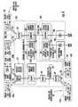
- FIG. 2shows a basic block diagram of a FADEC/ECU 14 that is operative as a bidirectional multiplexer for signals to and from the jet engine 12.
- the signalsinclude analog and digital signals and the FADEC/ECU 14 gives commands to the engine from the flight deck 20 of the aircraft 22. It also transmits engine status and health signals. Many signals are processed by the FADEC/ECU 14, which then transmits the signals over an ARINC 429 bus 24 in this non-limiting example at typically 10 kilobits per second to and from the flight deck 20.
- the WEMS module 10 of the present inventionhas a separate IP address (for each module), which is linked to the serial number of the engine.
- the WEMS moduleis mounted on the engine and interfaces with the FADEC/ECU such as through another port on the FADEC/ECU or directly into the ARINC 429 bus.
- the radio frequency transceiver capabilityis built into the WEMS module and is operative for recording, compressing and encrypting full flight data files. It typically will use a conformal antenna 30 that is formed as a small patch antenna the size of a postage stamp, for example, mounted on a casing 31 that forms a protective housing for the WEMS module 10.
- a conformal antennais preferred, a separate antenna could possibly be used depending on the cowling and engine type on which the WEMS module 10 is mounted.
- a separate antennacould be mounted on a separate location on the fuselage or other location for enhancing communication.
- the WEMS module 10can use an archival data store for recording, storing and encrypting and then later transmitting "full flight" engine data.
- the WEMS module 10 of the present inventioncan record hundreds of engine parameters with a preferred one second sampling frequency.
- the WEMS modulethus allows advanced prognostics and diagnostic techniques to increase "time on wing" and decrease engine maintenance costs.
- the WEMS module 10could be operative with jet engine diagnostic cells, such as used with prognostic and health management applications, including those designed by Impact Technologies, LLC of Rochester, New York.
- the WEMS module 10can download engine data by almost any type of radio frequency signal, including spread spectrum modulation techniques.
- the WEMS module 10could be operative with cellular, internet, or PSTN communication infrastructures to download full flight engine data files and upload algorithms or other data or programs. Each WEMS module will typically include a separate IP address such that it can be separately addressable for identification and upload and download of data.
- FIG. 3shows a high level block diagram of an aircraft 22 that includes the WEMS module 10, which downloads engine data and uploads data for onboard processing to and/or from an airport server 32, which could be operative with a communications network 34, such as a public switched telephone network (PSTN), the internet or a cellular infrastructure.
- the airport server 32includes a receiver and transmitter and communicates through the communications network 34 to a real-time analysis workstation or other similar processor 38 where the engine data can be analyzed to determine the best maintenance program for an engine, and thus, extend the time the engine remains on the plane without removing the engine.
- the real-time analysis workstation 38could be directly connected to the airport server or could receive data directly from the WEMS module 10, in accordance with the present invention.
- the WEMS module 10can be operative similar to the ground data link unit in that it stores data and transmits the data using a preferred spread spectrum or other wireless communications signal.
- the WEMS module 10is much smaller, however, and mounts directly onto the aircraft engine. It has fewer functions than the functions required by a large scale ground data link unit, which is operative with many aircraft components, including the DFDAU, DFDR and engine sensors.
- FIG. 4there is shown a representative example of an overall communications system architecture for a wireless spread spectrum data communications system that can be used with the WEMS module 10 of the present invention.
- the architecture in this examplehas three interlinked subsystems: (1) an engine WEMS subsystem 100; (2) a ground subsystem 200 (typically airport based but not necessarily at the airport); and (3) a remote engine data control center 300 used for analyzing any downloaded engine data.
- the WEMS system 100 for one aircraft 22could include a plurality of WEMS modules 10, each installed on an engine 100a-d. Two aircraft 22 and 22' are illustrated each with respective WEMS modules 10, 10'.
- Each WEMS module 10, 10'includes an airborne unit (AU) 102, 102', each which includes the processor, transceiver, memory and other necessary components. Each WEMS module 10, 10' is operative to communicate with a wireless router (WR) segment 201 of the ground subsystem 200 through a wireless communications link 120.
- AUairborne unit
- WRwireless router
- the wireless router segment 201routes the engine data files it receives from the WEMS module 10, either directly to an airport base station 202 via a wired Ethernet LAN 207, or indirectly through local area networks 207 and airport-resident wireless bridge segments 203 in this one non-limiting example.
- the wireless communication link 120can be a spread spectrum radio frequency (RF) link having a carrier frequency lying in an unlicensed portion of the electromagnetic spectrum, such as within the 2.4-2.5 GHz S-band as one non-limiting example.
- the wireless communication link 120could also be an RF, internet, cellular, or other link.
- the ground subsystem 200 in this exampleincludes a plurality of ground and/or airport-resident wireless router segments 201, one or more of which are distributed within the environments of the various airports served by the system.
- a respective ground and/or airport wireless router 201is operative to receive engine data that is wirelessly down-linked from a WEMS module 10.
- Each ground subsystem wireless router 201can forward engine data to a server/archive computer terminal 204 of a base station 202, which can reside on a local area network 207 of the ground subsystem 200 at an airport or other location.
- the base station 202can be coupled via a local communications path 207, to which a remote gateway (RG) segment 206 is interfaced over a communications path 230, to a central gateway (CG) segment 306 of a remote engine data control center 300, where engine data files from various aircraft are analyzed.
- the communications path 230can include an ISDN telephone company (Telco) land line
- the gateway segmentscan include standard LAN interfaces.
- Other communications networkssuch as cellular, internet, or other wireless communications can be used. It should be observed that other communications media, such as a satellite links or cellular, for example, may be employed for ground subsystem-to-control center communications without departing from the scope of the invention.
- the remote engine data control center 300could include a system controller (SC) segment 301 and a plurality of workstations (WS) 303, which are interlinked to the systems controller 301 via a local area network 305.
- SCsystem controller
- WSworkstations
- Engine safety, mainenance, and monitoring analystsare at the remote engine data control center 300 to evaluate the engine data files conveyed to the remote engine data control center 300 from the airport base station segments 202 of the ground subsystem 200.
- the respective workstations 303may be allocated for different purposes.
- the system controller 301can have a server/archive terminal unit 304 that preferably includes database management software for providing for efficient transfer and analysis of engine data files, as it retrieves downloaded files from the ground subsystem.
- database management softwaremay delete existing files from a base station segment's memory once the files have been retrieved.
- each WEMS module 10can include a bidirectional wireless (radio frequency carrier-based) subsystem containing a processing unit such as a microprocessor 132 and associated memory or data store 134, serving as both an archival data store 134a and a buffer 134b for communications, including packet communications.
- the memory 134is coupled to the FADEC/ECU.
- Processing unit 132can receive and compress the engine data and store the compressed data in its associated memory 134.
- a reportcan be generated by the processing unit 132, which includes many items of engine data.
- the engine data and reportscan be downloaded via the RF transceiver 136 and its preferred conformal antenna 30.
- the transceiver 136is operative with the wireless router 201 for upload and download of data.
- each of a plurality of sub-band channels of an unlicensed 2.4-2.5 GHz S-band segment of interest in this non-limiting examplecan be available and preferably used. Other unlicensed or licensed bands could be used.
- a wireless router 201could continuously broadcast an interrogation beacon that contains information representative of the emitted power level restrictions at an airport. Using an adaptive power unit within its transceiver, the WEMS module 10 could respond to this beacon signal by adjusting its emitted power to a level that will not exceed communication limitations imposed by the jurisdiction governing the airport.
- the wireless (RF) transceiver 136accesses the engine data file stored in memory 134, encrypts the engine data and transmits the engine data file via a selected sub-channel of the wireless ground communications link to a wireless router 201.
- the recipient wireless router 201forwards the data file to the base station segment temporarily until the file can be automatically transmitted over the communications path 230 to the remote engine data control center 300 for analysis. Further details of the associated components are described in the above-identified.
- the wireless engine monitoring systemuses similar components as in the GDL unit described in the '165 '179 and '734 patents, but has,reduced size and functionality for interfacing with the FADEC/ECU and mounting on the engine.
- the WEMS moduleis installed on the engine typically under the cowling and in a location to give the best antenna and transceiver functionality, but preferably adjacent or near the FADEC/ECU. It is possible to incorporate the WEMS module with the FADEC/ECU.
- the WEMS modulerecords, stores, encrypts and transmits "full flight" engine data and interfaces directly to the FADEC/ECU.
- a jet engineis described with reference to FIGS. 6 and 7 on which the wireless engine monitoring system (WEMS) module 10 of the present invention can be mounted.
- WEMSwireless engine monitoring system
- Each enginecan have one engine mounted WEMS module and each WEMS module can have a specific data address, such as an internet address or other IP address, to allow service providers to access the WEMS module and its data in near real time and perform "smart" maintenance. This address is linked to the engine serial number and will be used to store routine and critical engine information.
- the present inventioncan thus reduce engine maintenance cost per hour (MCPH).
- FIG. 6illustrates one cross-section of a jet engine indicated generally at 400, showing basic components and engine air flow FADEC/ECU control 402 to and from the jet engine that can be used for real time monitoring of engine events. These events could be downloaded during the first minute or so of initial take-off to a remote engine data control center 300 or saved to memory in the WEMS module and later downloaded to determine if "on wing" maintenance is warranted at the destination.
- the engine air flow FADEC/ECU control 402could include the core compartment bleeding; sump pressurization; sump venting; active clearance control; low pressure and high pressure recoup; and venting and draining functions. These functions could be monitored through basic FADEC/ECU control system 402, as known to those skilled in the art.
- the engine example in FIG. 6corresponds to a General Electric CF6-80C2 advanced design with a FADEC/ECU or PMC control having an N1 thrust management and common turbo machinery.
- this jet engineis illustrated, naturally other control systems for different jet engines could be used, as known to those skilled in the art.
- the engine as illustratedhas six variable stages and a ruggedized stage one blade with a low emission combuster and 30 pressurized nozzles and improved emissions. It has a Kevlar containment to give a lower containment weight and a composite fan OGV. It has an enhanced HPT with a DS stage of one blade material and a TBC, with advanced cooling and active clearance control.
- the fan moduleincludes an aluminum/Kevlar containment 404 and a 93-inch improved aero/blade 406. It has compositive OGV's 408 with an aluminum/composite aft fan case 410 and a titanium fan frame 412 for reduced losses. It additionally has a four stage orthogonal booster 414 and a variable bypass valve (VBV) between the fan struts (with 12 locations) 416.
- the engineincludes a compressor inlet temperature (CIT) probe 418.
- the high pressure compressorincludes an IGV shroud seal 420 and a blade dovetail sealing 422 with a trenched casing of stages 3-14 424.
- the compressorincludes a vane platform sealing 426 and a short cord stage 8 low loss bleed system 428 and improved rubcoat reduced clearances 430.
- the compressor rear frameincludes a combuster 430 and ignitor plug 432 with a fuel nozzle 434 and OGV 436. It includes a vent seal 438 and 4R/A/O seal 440 and 4R bearing 442 and 4B bearing 444. It also includes a 5R bearing 446 and 5R/A/O seal 448, a diffuser 450 and pressure balance seal 452.
- the compressor rear framealso includes a stage 1 nozzle 454.
- the high pressure turbine areaincludes an active clearance for control stages 1 and 2, and coated shrouds indicated at 456. It also includes directionally solidified stage 1 blades and damped blades 458 and a cooling air delivery system.
- the high pressure turbineinclude a thermally matched support structure, and an active clearance control and simplified impingement with a cradled vane support and linear ceiling.
- the improved inner structure load pathhas improved roundness control, solid shrouds and improved ceiling. These components are located in the area generally at 460 of the high pressure turbine area.
- Low pressure turbine technology areaincludes a clearance control 462, a 3600 case 464, aerodynamic struts 466 that remove swirl from the exit gas and a turbine rear frame 468 formed as a one piece casting.
- Many of these componentscan have sensors and structural force sensor that generate signals during initial take-off such that signals are relayed via the WEMS module to an on-ground maintenance crew and/or separate remote engine data control center having its own processor.
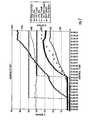
- FIG. 7illustrates components that were monitored during engine start in one example, including the engine hydraulic system, the oil pressure (psi), the engine cut-off switch, oil temperature (deg C), fuel flow (lb/hr), the N2L and N1L both in percentage terms, oil temperature and EGT, both in centigrade, and W f .
- Some of the rangesare shown on the vertical axis of the graph, while time is shown on the horizontal axis of the graph.
- This informationcan be downloaded via the WEMS module of the present invention to a ground based processor and a remote engine data control center can determine if on wing maintenance is warranted at the destination station.
Landscapes
- Engineering & Computer Science (AREA)
- General Physics & Mathematics (AREA)
- Physics & Mathematics (AREA)
- Aviation & Aerospace Engineering (AREA)
- Combustion & Propulsion (AREA)
- Chemical & Material Sciences (AREA)
- Automation & Control Theory (AREA)
- Computer Networks & Wireless Communication (AREA)
- Signal Processing (AREA)
- Mechanical Engineering (AREA)
- General Engineering & Computer Science (AREA)
- Astronomy & Astrophysics (AREA)
- Medical Informatics (AREA)
- General Health & Medical Sciences (AREA)
- Health & Medical Sciences (AREA)
- Computing Systems (AREA)
- Arrangements For Transmission Of Measured Signals (AREA)
- Testing Of Engines (AREA)
- Mobile Radio Communication Systems (AREA)
Description
- The Federal Aviation Administration and other international aviation regulatory agencies require commercial airlines to monitor the health and status of aircraft engines. Any health and status information is used to determine the current performance for an aircraft engine and determine if maintenance is required. Prior art techniques have been limited because of data latency and the limited amount of collected data restricted analysis. Typically, gross indicators were measured using prior art monitoring systems. Any resultant maintenance actions were reactive. For example, some prior art systems took a "snapshot" of only basic engine parameters, for example, when the aircraft had lifted to 1,000 feet after initial take-off. This data was limited to one time slot during flight and was not real time. This data never gave analysts a complete picture of an engine performance during flight. As a result, advanced prognostics and diagnostic techniques have not been used by prior art engine analysis systems.
- Many jet engine original equipment manufacturers (OEMs), jet engine service providers that are contractually bound under engine maintenance cost per hour (MCPH) agreements, airline transport companies and military and commercial aviation companies have desired a system and method to monitor performance of an aircraft engine in real time and archive that data. Up to now, prior art systems were limited in their analysis to the prior art data "snapshots" and did not go beyond gross indicators and reactive maintenance techniques. In some prior art techniques, airlines have complied with regulatory requirements using several different monitoring systems. In one monitoring system, limited engine parameters (e.g., N1, N2, EGT and Wf) have been logged by pilots in aircraft log books. As noted before, automated engine data also was recorded at take-off/cruise at 1,000 feet as a "snapshot" that is recorded either "on board" or downloaded via ACARS using a VHF communication data link. This engine data resulted in a limited engine analysis because only one "snapshot" of the engine performance had been used and the "snapshot" never gave a true indication of engine performance during flight of the aircraft.
- Harris Corporation of Melbourne, Florida has designed a system and method of recording performance of an aircraft engine using a ground data link unit that interfaces with numerous components of the aircraft, including the DFDAU, the aircraft digital flight data recorder DFDR, and the data multiplexing system commonly referred to as the Full Authority Digital Engine Control (FADEC) for larger jet turbine engines or Engine Control Unit (ECU) as sometimes referred with smaller jet turbine engines used on smaller aircraft, including turboprops or other engines generating less than 15,000 pounds of thrust. Hereinafter, the term "FADEC/ECU" will be used corresponding to either the term "FADEC" or "ECU" as used by the industry. Document
EP 1 316 908 A1 discloses an integrated system for monitoring a deployed product on a movable platform, gathering data about the deployed product, and disseminating the data about the deployed product. The system includes a server located on the movable platform capable of communication with the server from a remote location. The server communicates with a source of data about the deployed product. The system further includes a portal onto which data gathered by the server may be downloaded and with which one can upload information to the server. DocumentWO 03/056284 A2 - An example of the Harris Corporation ground data link unit is disclosed in commonly assigned
U.S. Patent No. 6,047,165 , and an engine monitoring system using the ground data link unit is disclosed inU.S. Patent Nos. 6,148,179 and6,353,734 , the disclosures. - In the '179 and '734 patents, the system and method as disclosed can provide a record of the performance of an aircraft engine by collecting engine data during engine operation, for example, in the ground data link unit, and downloading the collected engine data over a wideband spread spectrum communications signal to a ground based spread spectrum receiver. The signal is demodulated within a ground based spread spectrum receiver to obtain the engine data for further processing. It is also possible to upload data to the ground data link unit, such as algorithms, flight management files, video and entertainment files and other data files. Although the ground data link unit as disclosed in these patents is a major improvement over prior art solutions for engine monitoring, the disclosed ground data link unit is typically a large unit and interfaces with many airborne systems as described before. It would be advantageous to monitor engines in real time without resorting to the larger ground data link unit that interfaces with many systems, or by a smaller unit when the disclosed ground data link unit is not available.
- In accordance with the present invention the wireless engine monitoring system (WEMS) of the present invention overcomes the disadvantages of the prior art described above and is an engine mounted engine monitoring module mounted directly on the aircraft engine. It is not installed in an avionics department or similar fuselage location, such as the preferred location for a ground data link unit connected to many airborne units as disclosed in the '179 and '734 patents. The WEMS module is interfaced to the Full Authority Digital Engine Controller (FADEC)/Engine Control Unit (EDU) on the engine. The WEMS is a small module of about 2x2x4 inches and can record, store, encrypt and transmit "full flight" engine data. It interfaces directly to the FADEC/EDU and records hundreds of engine parameters with one second sampling frequency, as one non-limiting example. It is a miniaturized module with a preferred conformal antenna and RF transceiver to download (and upload) data using RF/802.11/cellular techniques, including any other spread spectrum techniques.
- The "full flight" engine data allows advanced prognostics and diagnostics techniques and increases engine "time on wing" and decreases engine maintenance costs. The WEMS data could be downloaded via RF/(802.11) spread spectrum/cellular to an airport server for processing and/or transported over the internet, PSTN, cellular system or other communications network to another workstation for real-time analysis. Data can be uploaded to the wireless engine monitoring system module, including algorithms for on-board processing.
- The system and method of the present invention is an automated wireless solution installed directly on the engine. It records full flight engine data for large and small turbine engines and has large megabyte files, using a high speed data link to extract. The system can use a wideband spread spectrum communications signal in accordance with 802.11 standards, e.g., the technology as disclosed in the '165 and '734 patents.
- In accordance with the present invention, the system and method provides a record of the performance of an aircraft engine. An engine monitoring module is mounted on the aircraft engine and collects engine data relating to operation of the aircraft engine. The engine monitoring module includes a transmitter for transmitting the engine data over a wireless communications signal. The receiver receives the transmitted engine data.
- In one aspect of the present invention, the transmitter preferably comprises a spread spectrum transmitter for transmitting the engine data over a wideband spread spectrum communications signal. A conformal antenna, such as a patch antenna, is preferably mounted on the engine monitoring module to which the wireless communications signal is transmitted. A processor is operative for receiving the engine data from the receiver and further processing of the engine data. The engine data can be transferred from the receiver to the processor using an internet, a public switched telephone network, a cellular network or other communications network.
- In yet another aspect of the present invention, a FADEC/ECU is operative with the aircraft engine for collecting engine data. The engine monitoring module is electrically connected to the FADEC/ECU for collecting engine data. A data address is preferably assigned to the engine monitoring module and links the data address to an engine serial number for tracking the aircraft engine. This data address preferably comprises an internet address. The engine monitoring module could also include a receiver as part of a transceiver for uploading data for onboard processing, including various algorithms used for engine monitoring.
- Other objects, features and advantages of the present invention will become apparent from the detailed description of the invention which follows, when considered in light of the accompanying drawings in which:
FIG. 1 is a partial fragmentary, isometric view of a jet engine showing the FADEC/ECU and the WEMS module mounted on the engine, the WEMS module interfacing with the FADEC/ECU for downloading engine monitoring data, in accordance with the present invention.FIG. 2 is a block diagram showing the aircraft engine and aircraft, and the WEMS module of the present invention interfaced with the FADEC/ECU for downloading full flight engine data files and uploading algorithms and other data.FIG. 3 is a fragmentary, block diagram showing WEMS engine data that can be downloaded to an airport server and transferred by PSTN, internet or cellular infrastructure to a real-time analysis workstation or other processor.FIG. 4 is a block diagram showing basic elements that can be used in the present invention.FIG. 5 is a block diagram showing basic components of a WEMS module that could be used in the present invention.FIG. 6 is a cross-section of an example of a jet engine that generates engine events to be collected and transmitted from the WEMS module of the present invention.FIG. 7 is a chart showing various jet engine event reports at engine start that could be monitored by the WEMS module of the present invention.- The present invention will now be described more fully hereinafter with reference to the accompanying drawings, in which preferred embodiments of the invention are shown. This invention may, however, be embodied in many different forms and should not be construed as limited to the embodiments set forth herein. Rather, these embodiments are provided so that this disclosure will be thorough and complete, and will fully convey the scope of the invention to those skilled in the art. Like numbers refer to like elements throughout, and prime notation is used to indicate similar elements in alternative embodiments.
- The present invention is a wireless engine monitoring system (WEMS) and can use basic components of the ground data link unit as disclosed in the '165, '179 and '734 patents. The system of the present invention is reduced in function and size for a WEMS module and is mounted directly to the jet engine and preferably interfaces with the FADEC/ECU. The present invention is operative for downloading data using a wireless communications signal, preferably a wideband spread spectrum communications signal, in a similar manner to the wireless ground link-based aircraft data communications system disclosed in the above '165, '179 and '734 patents. It could also download via any RF connection.
FIG. 1 shows aWEMS module 10 that is mounted directly on thejet engine 12 and electrically connected to the FADEC/ECU control unit 14, which is also mounted on the jet engine. Thejet engine 12 shows basic elements of theturbine 16 and other components. Thejet engine cowling 18 is shown in dashed lines andWEMS module 10 is disposed within the cowling. TheWEMS module 10 of the present invention includes basic functional RF and memory components, such as disclosed in the ground data link unit of the incorporated by reference '165, '179 and '734 patents. The WEMS module can be mounted at different locations on the engine depending on the type of preferred conformal antenna and the nature of thecowling 18 used in the jet engine.FIG. 2 shows a basic block diagram of a FADEC/ECU 14 that is operative as a bidirectional multiplexer for signals to and from thejet engine 12. The signals include analog and digital signals and the FADEC/ECU 14 gives commands to the engine from theflight deck 20 of theaircraft 22. It also transmits engine status and health signals. Many signals are processed by the FADEC/ECU 14, which then transmits the signals over an ARINC 429bus 24 in this non-limiting example at typically 10 kilobits per second to and from theflight deck 20.- The
WEMS module 10 of the present invention has a separate IP address (for each module), which is linked to the serial number of the engine. The WEMS module is mounted on the engine and interfaces with the FADEC/ECU such as through another port on the FADEC/ECU or directly into the ARINC 429 bus. The radio frequency transceiver capability is built into the WEMS module and is operative for recording, compressing and encrypting full flight data files. It typically will use aconformal antenna 30 that is formed as a small patch antenna the size of a postage stamp, for example, mounted on acasing 31 that forms a protective housing for theWEMS module 10. Although a conformal antenna is preferred, a separate antenna could possibly be used depending on the cowling and engine type on which theWEMS module 10 is mounted. A separate antenna could be mounted on a separate location on the fuselage or other location for enhancing communication. - The
WEMS module 10 can use an archival data store for recording, storing and encrypting and then later transmitting "full flight" engine data. TheWEMS module 10 of the present invention can record hundreds of engine parameters with a preferred one second sampling frequency. The WEMS module thus allows advanced prognostics and diagnostic techniques to increase "time on wing" and decrease engine maintenance costs. For example, theWEMS module 10 could be operative with jet engine diagnostic cells, such as used with prognostic and health management applications, including those designed by Impact Technologies, LLC of Rochester, New York. TheWEMS module 10 can download engine data by almost any type of radio frequency signal, including spread spectrum modulation techniques. TheWEMS module 10 could be operative with cellular, internet, or PSTN communication infrastructures to download full flight engine data files and upload algorithms or other data or programs. Each WEMS module will typically include a separate IP address such that it can be separately addressable for identification and upload and download of data. FIG. 3 shows a high level block diagram of anaircraft 22 that includes theWEMS module 10, which downloads engine data and uploads data for onboard processing to and/or from anairport server 32, which could be operative with acommunications network 34, such as a public switched telephone network (PSTN), the internet or a cellular infrastructure. Theairport server 32 includes a receiver and transmitter and communicates through thecommunications network 34 to a real-time analysis workstation or othersimilar processor 38 where the engine data can be analyzed to determine the best maintenance program for an engine, and thus, extend the time the engine remains on the plane without removing the engine. The real-time analysis workstation 38 could be directly connected to the airport server or could receive data directly from theWEMS module 10, in accordance with the present invention.- As noted before, the
WEMS module 10 can be operative similar to the ground data link unit in that it stores data and transmits the data using a preferred spread spectrum or other wireless communications signal. TheWEMS module 10 is much smaller, however, and mounts directly onto the aircraft engine. It has fewer functions than the functions required by a large scale ground data link unit, which is operative with many aircraft components, including the DFDAU, DFDR and engine sensors. - Referring now to
FIG. 4 , there is shown a representative example of an overall communications system architecture for a wireless spread spectrum data communications system that can be used with theWEMS module 10 of the present invention. The architecture in this example has three interlinked subsystems: (1) anengine WEMS subsystem 100; (2) a ground subsystem 200 (typically airport based but not necessarily at the airport); and (3) a remote enginedata control center 300 used for analyzing any downloaded engine data. TheWEMS system 100 for oneaircraft 22 could include a plurality ofWEMS modules 10, each installed on anengine 100a-d. Twoaircraft 22 and 22' are illustrated each withrespective WEMS modules 10, 10'. EachWEMS module 10, 10' includes an airborne unit (AU) 102, 102', each which includes the processor, transceiver, memory and other necessary components. EachWEMS module 10, 10' is operative to communicate with a wireless router (WR)segment 201 of theground subsystem 200 through a wireless communications link 120. The following description proceeds with reference to oneaircraft 22 andWEMS module 10 for purposes of description. - The
wireless router segment 201 routes the engine data files it receives from theWEMS module 10, either directly to anairport base station 202 via a wiredEthernet LAN 207, or indirectly throughlocal area networks 207 and airport-residentwireless bridge segments 203 in this one non-limiting example. Thewireless communication link 120 can be a spread spectrum radio frequency (RF) link having a carrier frequency lying in an unlicensed portion of the electromagnetic spectrum, such as within the 2.4-2.5 GHz S-band as one non-limiting example. Thewireless communication link 120 could also be an RF, internet, cellular, or other link. - The
ground subsystem 200 in this example includes a plurality of ground and/or airport-residentwireless router segments 201, one or more of which are distributed within the environments of the various airports served by the system. A respective ground and/orairport wireless router 201 is operative to receive engine data that is wirelessly down-linked from aWEMS module 10. Each groundsubsystem wireless router 201 can forward engine data to a server/archive computer terminal 204 of abase station 202, which can reside on alocal area network 207 of theground subsystem 200 at an airport or other location. - The
base station 202 can be coupled via alocal communications path 207, to which a remote gateway (RG)segment 206 is interfaced over acommunications path 230, to a central gateway (CG)segment 306 of a remote enginedata control center 300, where engine data files from various aircraft are analyzed. As a non-limiting example, thecommunications path 230 can include an ISDN telephone company (Telco) land line, and the gateway segments can include standard LAN interfaces. Other communications networks, such as cellular, internet, or other wireless communications can be used. It should be observed that other communications media, such as a satellite links or cellular, for example, may be employed for ground subsystem-to-control center communications without departing from the scope of the invention. - The remote engine
data control center 300 could include a system controller (SC)segment 301 and a plurality of workstations (WS) 303, which are interlinked to thesystems controller 301 via alocal area network 305. Engine safety, mainenance, and monitoring analysts are at the remote enginedata control center 300 to evaluate the engine data files conveyed to the remote enginedata control center 300 from the airportbase station segments 202 of theground subsystem 200. Therespective workstations 303 may be allocated for different purposes. - The
system controller 301 can have a server/archive terminal unit 304 that preferably includes database management software for providing for efficient transfer and analysis of engine data files, as it retrieves downloaded files from the ground subsystem. As a non-limiting example, such database management software may delete existing files from a base station segment's memory once the files have been retrieved. - As described briefly above, and as diagrammatically illustrated in
FIG. 5 , eachWEMS module 10 can include a bidirectional wireless (radio frequency carrier-based) subsystem containing a processing unit such as amicroprocessor 132 and associated memory ordata store 134, serving as both anarchival data store 134a and abuffer 134b for communications, including packet communications. Thememory 134 is coupled to the FADEC/ECU.Processing unit 132 can receive and compress the engine data and store the compressed data in its associatedmemory 134. A report can be generated by theprocessing unit 132, which includes many items of engine data. - The engine data and reports can be downloaded via the
RF transceiver 136 and its preferredconformal antenna 30. To provide bidirectional RF communication capability, thetransceiver 136 is operative with thewireless router 201 for upload and download of data. - If the RF communication link is spread spectrum, and a preferred 802.11 link, each of a plurality of sub-band channels of an unlicensed 2.4-2.5 GHz S-band segment of interest in this non-limiting example can be available and preferably used. Other unlicensed or licensed bands could be used. A
wireless router 201 could continuously broadcast an interrogation beacon that contains information representative of the emitted power level restrictions at an airport. Using an adaptive power unit within its transceiver, theWEMS module 10 could respond to this beacon signal by adjusting its emitted power to a level that will not exceed communication limitations imposed by the jurisdiction governing the airport. The wireless (RF)transceiver 136 then accesses the engine data file stored inmemory 134, encrypts the engine data and transmits the engine data file via a selected sub-channel of the wireless ground communications link to awireless router 201. - The
recipient wireless router 201 forwards the data file to the base station segment temporarily until the file can be automatically transmitted over thecommunications path 230 to the remote enginedata control center 300 for analysis. Further details of the associated components are described in the above-identified. - In the present claimed invention, the wireless engine monitoring system (WEMS) uses similar components as in the GDL unit described in the '165 '179 and '734 patents, but has,reduced size and functionality for interfacing with the FADEC/ECU and mounting on the engine. The WEMS module is installed on the engine typically under the cowling and in a location to give the best antenna and transceiver functionality, but preferably adjacent or near the FADEC/ECU. It is possible to incorporate the WEMS module with the FADEC/ECU. The WEMS module records, stores, encrypts and transmits "full flight" engine data and interfaces directly to the FADEC/ECU. It can record hundreds of engine parameters with one second sampling frequency as an example and is a miniaturized module with a conformal antenna. It acquires "full flight" engine data and allows advanced prognostics and diagnostics techniques either on-board or preferably at a remote workstation to increase "time on wing" and decrease engine maintenance costs. It is an automated wireless solution installed directly on the engine and records full flight engine data for large turbine engines and results in large megabyte files using the high speed data link as described before. It is an improvement over those systems that record only a few engine data "snapshots," resulting in limited data and limited analysis.
- For purposes of reference, a jet engine is described with reference to
FIGS. 6 and7 on which the wireless engine monitoring system (WEMS)module 10 of the present invention can be mounted. Each engine can have one engine mounted WEMS module and each WEMS module can have a specific data address, such as an internet address or other IP address, to allow service providers to access the WEMS module and its data in near real time and perform "smart" maintenance. This address is linked to the engine serial number and will be used to store routine and critical engine information. The present invention can thus reduce engine maintenance cost per hour (MCPH). FIG. 6 illustrates one cross-section of a jet engine indicated generally at 400, showing basic components and engine air flow FADEC/ECU control 402 to and from the jet engine that can be used for real time monitoring of engine events. These events could be downloaded during the first minute or so of initial take-off to a remote enginedata control center 300 or saved to memory in the WEMS module and later downloaded to determine if "on wing" maintenance is warranted at the destination.- For purposes of clarity, reference numerals to describe this jet engine begin in the 400 series. As shown in
FIG. 6 , the engine air flow FADEC/ECU control 402 could include the core compartment bleeding; sump pressurization; sump venting; active clearance control; low pressure and high pressure recoup; and venting and draining functions. These functions could be monitored through basic FADEC/ECU control system 402, as known to those skilled in the art. The engine example inFIG. 6 corresponds to a General Electric CF6-80C2 advanced design with a FADEC/ECU or PMC control having an N1 thrust management and common turbo machinery. Although this jet engine is illustrated, naturally other control systems for different jet engines could be used, as known to those skilled in the art. - The engine as illustrated has six variable stages and a ruggedized stage one blade with a low emission combuster and 30 pressurized nozzles and improved emissions. It has a Kevlar containment to give a lower containment weight and a composite fan OGV. It has an enhanced HPT with a DS stage of one blade material and a TBC, with advanced cooling and active clearance control.
- The fan module includes an aluminum/
Kevlar containment 404 and a 93-inch improved aero/blade 406. It has compositive OGV's 408 with an aluminum/compositeaft fan case 410 and atitanium fan frame 412 for reduced losses. It additionally has a four stageorthogonal booster 414 and a variable bypass valve (VBV) between the fan struts (with 12 locations) 416. The engine includes a compressor inlet temperature (CIT)probe 418. - The high pressure compressor includes an
IGV shroud seal 420 and a blade dovetail sealing 422 with a trenched casing of stages 3-14 424. The compressor includes a vane platform sealing 426 and a short cord stage 8 lowloss bleed system 428 and improved rubcoat reducedclearances 430. - The compressor rear frame includes a
combuster 430 and ignitor plug 432 with afuel nozzle 434 andOGV 436. It includes avent seal 438 and 4R/A/O seal 440 and 4R bearing 442 and 4B bearing 444. It also includes a5R bearing 446 and 5R/A/O seal 448, adiffuser 450 andpressure balance seal 452. The compressor rear frame also includes a stage 1 nozzle 454. - The high pressure turbine area includes an active clearance for control stages 1 and 2, and coated shrouds indicated at 456. It also includes directionally solidified stage 1 blades and damped blades 458 and a cooling air delivery system. The high pressure turbine include a thermally matched support structure, and an active clearance control and simplified impingement with a cradled vane support and linear ceiling. The improved inner structure load path has improved roundness control, solid shrouds and improved ceiling. These components are located in the area generally at 460 of the high pressure turbine area.
- Low pressure turbine technology area includes a
clearance control 462, a 3600case 464,aerodynamic struts 466 that remove swirl from the exit gas and a turbinerear frame 468 formed as a one piece casting. - Many of these components can have sensors and structural force sensor that generate signals during initial take-off such that signals are relayed via the WEMS module to an on-ground maintenance crew and/or separate remote engine data control center having its own processor.
FIG. 7 illustrates components that were monitored during engine start in one example, including the engine hydraulic system, the oil pressure (psi), the engine cut-off switch, oil temperature (deg C), fuel flow (lb/hr), the N2L and N1L both in percentage terms, oil temperature and EGT, both in centigrade, and Wf. Some of the ranges are shown on the vertical axis of the graph, while time is shown on the horizontal axis of the graph.- This information can be downloaded via the WEMS module of the present invention to a ground based processor and a remote engine data control center can determine if on wing maintenance is warranted at the destination station.
Claims (9)
- A system for providing a record of the performance of an aircraft engine (12) comprising:an engine monitoring module (10) mounted on the aircraft engine (12) adapted to collect engine data relating to operation of the aircraft engine, said engine monitoring module (10) having an assigned data address that is linked to a serial number of the aircraft engine (12) for tracking the aircraft engine (12), andfurther comprising a transmitter built into the engine monitoring module (10) and adapted to transmit the engine data over a wireless communications signal; anda receiver for receiving the transmitted engine data.
- A system according to claim 1, wherein said transmitter comprises a spread spectrum transmitter adapted to transmit the engine data over a wideband spread spectrum communications signal.
- A system according to claim 1, and further comprising a conformal antenna (30) mounted on the engine monitoring module (10) through which the wireless communications signal is transmitted.
- A system according to claim 3, and further comprising a Full Authority Digital Engine Control/Engine Control Unit, FADEC/ECU, operative with the aircraft engine (12) for collecting engine data from the aircraft engine (12), wherein said engine monitoring module (10) is operative with said FADEC/ECU for collecting engine data therefrom.
- A system according to claim 3, further comprising a wireless router at an airport adapted to transmit a beacon signal containing information representative of the emitted power level restrictions at an airport, and wherein the monitoring module (10) adapted to respond to said beacon signal by adjusting its emitted power to a level that will not exceed communication limitations imposed by the jurisdiction governing the airport.
- A method of providing a record of the performance of an aircraft engine (12) comprising the steps of:collecting aircraft engine data within an engine monitoring module (10) mounted on the aircraft engine (12);assigning a data address that is linked to a serial number of the aircraft engine (12) for tracking the aircraft engine, andtransmitting the engine data that has been collected in the engine monitoring module (10) over a wireless communications signal from a transmitter built into the engine monitoring module (10) to a receiver.
- A method according to claim 6, and further comprising the step of downloading the engine data over a wideband spread spectrum communications signal.
- A method according to claim 6, and further comprising the step of transmitting the wireless communications signal via a conformal antenna (30) mounted on the engine monitoring module (10).
- A method according to claim 6, and further comprising the step of transmitting a beacon signal by a wireless router at an airport containing information representative of the emitted power level restrictions at an airport, and of responding by the monitoring module (10) by adjusting its emitted power to a level that will not exceed communication limitations imposed by the jurisdiction governing the airport.
Priority Applications (2)
| Application Number | Priority Date | Filing Date | Title |
|---|---|---|---|
| EP11009467.9AEP2442285B1 (en) | 2003-07-23 | 2004-06-28 | Wireless engine monitoring system |
| EP11009468.7AEP2450861B1 (en) | 2003-07-23 | 2004-06-28 | Wireless engine monitoring system |
Applications Claiming Priority (3)
| Application Number | Priority Date | Filing Date | Title |
|---|---|---|---|
| US48936803P | 2003-07-23 | 2003-07-23 | |
| US10/774,578US6943699B2 (en) | 2003-07-23 | 2004-02-09 | Wireless engine monitoring system |
| PCT/US2004/020618WO2005040963A2 (en) | 2003-07-23 | 2004-06-28 | Wireless engine monitoring system |
Related Child Applications (2)
| Application Number | Title | Priority Date | Filing Date |
|---|---|---|---|
| EP11009468.7Division-Into | 2011-11-30 | ||
| EP11009467.9Division-Into | 2011-11-30 |
Publications (3)
| Publication Number | Publication Date |
|---|---|
| EP1654715A2 EP1654715A2 (en) | 2006-05-10 |
| EP1654715A4 EP1654715A4 (en) | 2011-12-28 |
| EP1654715B1true EP1654715B1 (en) | 2013-04-10 |
Family
ID=34083526
Family Applications (3)
| Application Number | Title | Priority Date | Filing Date |
|---|---|---|---|
| EP11009467.9AExpired - LifetimeEP2442285B1 (en) | 2003-07-23 | 2004-06-28 | Wireless engine monitoring system |
| EP04816757.1AExpired - LifetimeEP1654715B1 (en) | 2003-07-23 | 2004-06-28 | Wireless engine monitoring system |
| EP11009468.7AExpired - LifetimeEP2450861B1 (en) | 2003-07-23 | 2004-06-28 | Wireless engine monitoring system |
Family Applications Before (1)
| Application Number | Title | Priority Date | Filing Date |
|---|---|---|---|
| EP11009467.9AExpired - LifetimeEP2442285B1 (en) | 2003-07-23 | 2004-06-28 | Wireless engine monitoring system |
Family Applications After (1)
| Application Number | Title | Priority Date | Filing Date |
|---|---|---|---|
| EP11009468.7AExpired - LifetimeEP2450861B1 (en) | 2003-07-23 | 2004-06-28 | Wireless engine monitoring system |
Country Status (6)
| Country | Link |
|---|---|
| US (6) | US6943699B2 (en) |
| EP (3) | EP2442285B1 (en) |
| JP (2) | JP2007516377A (en) |
| KR (1) | KR100784607B1 (en) |
| CA (1) | CA2533495C (en) |
| WO (1) | WO2005040963A2 (en) |
Families Citing this family (131)
| Publication number | Priority date | Publication date | Assignee | Title |
|---|---|---|---|---|
| US20030105565A1 (en)* | 2001-12-03 | 2003-06-05 | Loda David C. | Integrated internet portal and deployed product microserver management system |
| US6943699B2 (en)* | 2003-07-23 | 2005-09-13 | Harris Corporation | Wireless engine monitoring system |
| US8332910B2 (en)* | 2003-10-13 | 2012-12-11 | General Electric Company | Method and apparatus for selective data control |
| US20050278756A1 (en)* | 2004-06-12 | 2005-12-15 | Brown Alan E | Information processing apparatus featuring a multi-subsystem wireless bus architecture |
| WO2006011141A2 (en)* | 2004-07-25 | 2006-02-02 | Israel Aerospace Industries Ltd. | Method and system for the acquisition of data and for the display of data |
| US9576404B2 (en) | 2004-09-16 | 2017-02-21 | Harris Corporation | System and method of transmitting data from an aircraft |
| US8854980B2 (en) | 2005-05-06 | 2014-10-07 | Lockheed Martin Corporation | Switching module |
| FR2890685B1 (en)* | 2005-09-14 | 2007-12-14 | Snecma | TURBINE HIGH ROTOR ROTOR AUTONOMOUS ROTOR CONTROL IN A TURBOMACHINE |
| US20070135987A1 (en)* | 2005-11-22 | 2007-06-14 | Honeywell International | System and method for turbine engine igniter lifing |
| US7660652B2 (en)* | 2006-02-02 | 2010-02-09 | Signature Control Systems, Inc. | Method, system and device for monitoring vehicle usage |
| US7431557B2 (en)* | 2006-05-25 | 2008-10-07 | General Electric Company | Compensating for blade tip clearance deterioration in active clearance control |
| EP2062365B1 (en)* | 2006-09-15 | 2017-06-07 | Thales Avionics, Inc. | System and method for wirelessly transferring content to and from an aircraft |
| US7854127B2 (en)* | 2006-10-24 | 2010-12-21 | United Technologies Corporation | Smart wireless engine sensor |
| US7698927B2 (en)* | 2007-01-30 | 2010-04-20 | The Boeing Company | Methods and systems for measuring atmospheric water content |
| US8666569B2 (en)* | 2007-02-16 | 2014-03-04 | Honeywell International Inc. | Methods and systems for health monitoring for aircraft |
| US20090030563A1 (en)* | 2007-07-26 | 2009-01-29 | United Technologies Corp. | Systems And Methods For Providing Localized Heat Treatment Of Metal Components |
| US8126628B2 (en)* | 2007-08-03 | 2012-02-28 | General Electric Company | Aircraft gas turbine engine blade tip clearance control |
| US20090070841A1 (en)* | 2007-09-12 | 2009-03-12 | Proximetry, Inc. | Systems and methods for delivery of wireless data and multimedia content to aircraft |
| US8032330B2 (en)* | 2008-03-07 | 2011-10-04 | Nokia Corporation | Electromagnetic interference sensor device and method and computer program |
| US8195118B2 (en) | 2008-07-15 | 2012-06-05 | Linear Signal, Inc. | Apparatus, system, and method for integrated phase shifting and amplitude control of phased array signals |
| US7872603B2 (en)* | 2008-09-04 | 2011-01-18 | The Boeing Company | Method and apparatus for making airborne radar horizon measurements to measure atmospheric refractivity profiles |
| GB0816728D0 (en)* | 2008-09-15 | 2008-10-22 | Rolls Royce Plc | Improvements in or relating to engine monitoring and control |
| US20100263900A1 (en)* | 2009-04-20 | 2010-10-21 | Divincenzo Gregory | Reconfigurable full authority digital electronic control housing |
| US9092029B2 (en)* | 2009-04-21 | 2015-07-28 | Hamilton Sundstrand Corporation | Vehicle monitoring system |
| KR101065485B1 (en)* | 2009-05-18 | 2011-09-19 | 명품기업주식회사 | Engine wireless monitoring system |
| US8467949B2 (en)* | 2009-05-29 | 2013-06-18 | Honeywell International Inc. | Methods and systems for turbine line replaceable unit fault detection and isolation during engine startup |
| US8054204B2 (en)* | 2009-05-29 | 2011-11-08 | United Technologies Corporation | Method for remotely updating wireless sensors |
| US8306689B2 (en)* | 2009-08-11 | 2012-11-06 | The United States Of America As Represented By The Secretary Of The Navy | Integrated net-centric diagnostics dataflow for avionics systems |
| US8872719B2 (en) | 2009-11-09 | 2014-10-28 | Linear Signal, Inc. | Apparatus, system, and method for integrated modular phased array tile configuration |
| US8732286B2 (en) | 2010-03-31 | 2014-05-20 | Honeywell International Inc. | Health management systems with shadow modules |
| FR2962617A1 (en)* | 2010-07-07 | 2012-01-13 | Eurocopter France | DISTRIBUTED, MODULAR AND CONFIGURABLE COMMUNICATION NETWORK FOR AN ON-ROAD AVIONIC SYSTEM. |
| US8965291B2 (en) | 2010-07-13 | 2015-02-24 | United Technologies Corporation | Communication of avionic data |
| FR2971595B1 (en)* | 2011-02-15 | 2013-03-22 | Snecma | MONITORING AN AIRCRAFT ENGINE TO ANTICIPATE MAINTENANCE OPERATIONS |
| CN102416821A (en)* | 2011-07-27 | 2012-04-18 | 中国国际航空股份有限公司 | Data processing method for aircraft system |
| US8246292B1 (en)* | 2012-01-31 | 2012-08-21 | United Technologies Corporation | Low noise turbine for geared turbofan engine |
| US20160130949A1 (en) | 2012-01-31 | 2016-05-12 | United Technologies Corporation | Low noise turbine for geared turbofan engine |
| US9092920B2 (en) | 2012-03-27 | 2015-07-28 | United Technologies Corporation | System and method for managing a vehicle and a fleet of vehicles |
| FR2988978B1 (en)* | 2012-03-28 | 2014-06-27 | Safran | FADEC BOX SUPPORT IN COMPOSITE MATERIAL |
| US9152146B2 (en) | 2012-06-06 | 2015-10-06 | Harris Corporation | Wireless engine monitoring system and associated engine wireless sensor network |
| US9026279B2 (en) | 2012-06-06 | 2015-05-05 | Harris Corporation | Wireless engine monitoring system and configurable wireless engine sensors |
| US9816897B2 (en) | 2012-06-06 | 2017-11-14 | Harris Corporation | Wireless engine monitoring system and associated engine wireless sensor network |
| US9026273B2 (en) | 2012-06-06 | 2015-05-05 | Harris Corporation | Wireless engine monitoring system with multiple hop aircraft communications capability and on-board processing of engine data |
| US20140075506A1 (en)* | 2012-09-13 | 2014-03-13 | iJet Technologies, Inc. | Extensible and Scalable Distributed Computing and Communication Remote Services Platform for Telemetry Collection Adaptive Data Driven Application Hosting, and Control Services |
| WO2014051661A1 (en)* | 2012-09-27 | 2014-04-03 | United Technologies Corporation | Turbomachine control system |
| US9624834B2 (en) | 2012-09-28 | 2017-04-18 | United Technologies Corporation | Low noise compressor rotor for geared turbofan engine |
| US20160138474A1 (en) | 2012-09-28 | 2016-05-19 | United Technologies Corporation | Low noise compressor rotor for geared turbofan engine |
| WO2014051662A1 (en) | 2012-09-28 | 2014-04-03 | United Technologies Corporation | Gas turbine engine having support structure with swept leading edge |
| CN103728965B (en)* | 2012-10-15 | 2017-02-22 | 中航商用航空发动机有限责任公司 | Monitoring device and method for aircraft engine and FADEC system |
| IN2015DN03214A (en) | 2012-10-25 | 2015-10-02 | Bae Systems Plc | |
| EP2725442A1 (en)* | 2012-10-25 | 2014-04-30 | BAE Systems PLC | Control system and method for unmanned vehicles |
| US9794346B2 (en) | 2012-12-11 | 2017-10-17 | The Boeing Company | Monitoring systems of a vehicle by generating and transmitting customized information messages to wireless networked computers |
| US8787904B1 (en)* | 2013-03-12 | 2014-07-22 | Smartsky Networks LLC | Aircraft based wireless communication system |
| US11719161B2 (en) | 2013-03-14 | 2023-08-08 | Raytheon Technologies Corporation | Low noise turbine for geared gas turbine engine |
| US10605172B2 (en) | 2013-03-14 | 2020-03-31 | United Technologies Corporation | Low noise turbine for geared gas turbine engine |
| DE102013205004B4 (en)* | 2013-03-21 | 2015-07-02 | Airbus Operations Gmbh | Black box, airplane with black box and method for reading flight data from a black box |
| US9336248B2 (en)* | 2013-04-24 | 2016-05-10 | The Boeing Company | Anomaly detection in chain-of-custody information |
| WO2014210215A1 (en) | 2013-06-25 | 2014-12-31 | Fedex Corporation | Transport communication management |
| EP3019722B1 (en)* | 2013-07-09 | 2018-11-21 | United Technologies Corporation | Plated polymer components for a gas turbine engine |
| US9563580B2 (en) | 2013-07-25 | 2017-02-07 | North Flight Data Systems, LLC | System, methodology, and process for wireless transmission of sensor data onboard an aircraft to a portable electronic device |
| JP6216183B2 (en)* | 2013-08-22 | 2017-10-18 | 三菱航空機株式会社 | Control system mounted on aircraft and aircraft |
| US9420356B2 (en)* | 2013-08-27 | 2016-08-16 | Siemens Energy, Inc. | Wireless power-receiving assembly for a telemetry system in a high-temperature environment of a combustion turbine engine |
| US10885010B2 (en) | 2013-12-18 | 2021-01-05 | Federal Express Corporation | Methods and systems for data structure optimization |
| US9230208B2 (en) | 2013-12-18 | 2016-01-05 | International Business Machines Corporation | Haptic-based artificial neural network training |
| US9826039B2 (en) | 2014-02-04 | 2017-11-21 | Honeywell International Inc. | Configurable communication systems and methods for communication |
| US9854594B2 (en) | 2014-03-31 | 2017-12-26 | International Business Machines Corporation | Wireless cross-connect switch |
| FR3028067B1 (en)* | 2014-11-05 | 2016-12-30 | Snecma | VALIDATION TOOL FOR A SYSTEM FOR MONITORING AN AIRCRAFT ENGINE |
| US10196930B2 (en) | 2014-12-18 | 2019-02-05 | United Technologies Corporation | System and method for controlling an environmental condition of an engine electronic component |
| CA2915233C (en)* | 2015-01-08 | 2018-12-04 | David A. Topol | Low noise compressor rotor for geared turbofan engine |
| US10590855B2 (en) | 2015-02-03 | 2020-03-17 | United Technologies Corporation | Distributed electrical architecture for a gas turbine engine |
| US9607452B2 (en) | 2015-04-21 | 2017-03-28 | United Technologies Corporation | Electronic module integration for harsh environment machines |
| FR3038994B1 (en)* | 2015-07-16 | 2017-07-07 | Airbus Operations Sas | SYSTEM, DEVICE AND METHOD FOR RECORDING DATA IN AN AIRCRAFT |
| US9885250B2 (en)* | 2015-10-23 | 2018-02-06 | United Technologies Corporation | Autonomous engine health management system |
| FR3044439B1 (en)* | 2015-11-27 | 2019-11-15 | Safran Aircraft Engines | METHOD FOR MONITORING THE OPERATION OF AN AIRCRAFT |
| US10598047B2 (en)* | 2016-02-29 | 2020-03-24 | United Technologies Corporation | Low-power bowed rotor prevention system |
| US10035609B2 (en) | 2016-03-08 | 2018-07-31 | Harris Corporation | Wireless engine monitoring system for environmental emission control and aircraft networking |
| FR3050876B1 (en)* | 2016-04-28 | 2019-07-05 | Turbomeca | COVER FOR AN AIRCRAFT ENGINE COMPRISING A RADIO-IDENTIFICATION READER ANTENNA |
| US10587307B2 (en) | 2016-06-20 | 2020-03-10 | Ge Aviation Systems, Llc | Transmission of power and communication of signals over fuel and hydraulic lines in a vehicle |
| US10787933B2 (en) | 2016-06-20 | 2020-09-29 | Raytheon Technologies Corporation | Low-power bowed rotor prevention and monitoring system |
| US10454525B2 (en) | 2016-06-20 | 2019-10-22 | Ge Aviation Systems Llc | Communication of signals over fuel lines in a vehicle |
| US9972896B2 (en)* | 2016-06-23 | 2018-05-15 | General Electric Company | Wireless aircraft engine monitoring system |
| US10093436B2 (en)* | 2016-06-23 | 2018-10-09 | General Electric Company | Wireless aircraft engine communication system |
| US10444748B2 (en) | 2016-06-30 | 2019-10-15 | Ge Aviation Systems Llc | In-situ measurement logging by wireless communication unit for communicating engine data |
| US10529150B2 (en) | 2016-06-30 | 2020-01-07 | Aviation Systems LLC | Remote data loading for configuring wireless communication unit for communicating engine data |
| US10467016B2 (en) | 2016-06-30 | 2019-11-05 | General Electric Company | Managing an image boot |
| US10470114B2 (en) | 2016-06-30 | 2019-11-05 | General Electric Company | Wireless network selection |
| US10681132B2 (en) | 2016-06-30 | 2020-06-09 | Ge Aviation Systems Llc | Protocol for communicating engine data to wireless communication unit |
| US10712377B2 (en) | 2016-06-30 | 2020-07-14 | Ge Aviation Systems Llc | Antenna diagnostics for wireless communication unit for communicating engine data |
| US20180005459A1 (en)* | 2016-06-30 | 2018-01-04 | Ge Aviation Systems Llc | Triggering Scheme for Communicating Engine Data |
| US10764747B2 (en)* | 2016-06-30 | 2020-09-01 | Ge Aviation Systems Llc | Key management for wireless communication system for communicating engine data |
| US10318451B2 (en) | 2016-06-30 | 2019-06-11 | Ge Aviation Systems Llc | Management of data transfers |
| US10200110B2 (en) | 2016-06-30 | 2019-02-05 | Ge Aviation Systems Llc | Aviation protocol conversion |
| US10819601B2 (en) | 2016-06-30 | 2020-10-27 | Ge Aviation Systems Llc | Wireless control unit server for conducting connectivity test |
| US10065744B2 (en) | 2016-10-12 | 2018-09-04 | General Electric Company | System and method for using an engine model for multiple functions |
| FR3064070B1 (en)* | 2017-03-20 | 2021-02-26 | Safran Aircraft Engines | PROCESS FOR MONITORING THE ENGINES OF AN AIRCRAFT |
| BE1025077B1 (en)* | 2017-03-22 | 2018-10-23 | Safran Aero Boosters S.A. | TURBOMACHINE COVER WITH SCREEN |
| US10489991B2 (en) | 2017-04-10 | 2019-11-26 | Honeywell International Inc. | Engine health and life cycle tracking system |
| WO2018191730A1 (en) | 2017-04-13 | 2018-10-18 | Texas Tech University System | System and method for automated prediction and detection of component and system failures |
| GB201716499D0 (en)* | 2017-10-09 | 2017-11-22 | Rolls Royce Plc | Gas turbine engine fireproofing |
| US10760485B2 (en) | 2018-02-02 | 2020-09-01 | General Electric Company | Virtualizing data for a vehicle control system |
| US10902136B2 (en)* | 2018-11-15 | 2021-01-26 | Rolls-Royce Corporation | Method and apparatus for data transfer during maintenance activity in a network |
| US11254441B2 (en)* | 2018-11-29 | 2022-02-22 | Hamilton Sundstrand Corporation | Aircraft controller including multiple core processor with wireless transmission prognostic/diagnostic data capability |
| US11012146B2 (en)* | 2019-02-11 | 2021-05-18 | Pratt & Whitney Canada Corp. | System and method for aircraft data transmission |
| US20210104104A1 (en)* | 2019-02-11 | 2021-04-08 | Pratt & Whitney Canada Corp. | System and method for transmitting data from an aircraft |
| US11162382B2 (en)* | 2019-02-21 | 2021-11-02 | General Electric Company | Method and system for engine operation |
| CN110044634A (en)* | 2019-04-01 | 2019-07-23 | 绵阳小巨人动力设备有限公司 | A kind of micro turbojet engine state and performance monitor apparatus |
| CN110057590B (en)* | 2019-04-15 | 2021-05-07 | 中国航发湖南动力机械研究所 | Aircraft engine outfield data management system and method facing machine group |
| EP3726325B1 (en) | 2019-04-17 | 2022-08-24 | Raytheon Technologies Corporation | Gas turbine engine with dynamic data recording |
| EP3726480B1 (en) | 2019-04-17 | 2024-09-25 | RTX Corporation | Remote updates of a gas turbine engine |
| EP3726324B1 (en) | 2019-04-17 | 2023-03-01 | Raytheon Technologies Corporation | Gas turbine engine communication gateway with internal sensors |
| US10977877B2 (en) | 2019-04-17 | 2021-04-13 | Raytheon Technologies Corporation | Engine gateway with engine data storage |
| EP3726323B1 (en)* | 2019-04-17 | 2023-03-08 | Raytheon Technologies Corporation | Gas turbine engine communication gateway with integral antennas |
| US11492132B2 (en) | 2019-04-17 | 2022-11-08 | Raytheon Technologies Corporation | Gas turbine engine configuration data synchronization with a ground-based system |
| US11208916B2 (en) | 2019-04-17 | 2021-12-28 | Raytheon Technologies Corporation | Self-healing remote dynamic data recording |
| US11913643B2 (en) | 2019-04-17 | 2024-02-27 | Rtx Corporation | Engine wireless sensor system with energy harvesting |
| US10970169B2 (en) | 2019-06-27 | 2021-04-06 | General Electric Company | Data configuration management system for an engine |
| EP3798994A1 (en)* | 2019-09-26 | 2021-03-31 | General Electric Company | Devices, systems, and methods for routing data to distributed devices in aircraft |
| FR3103211B1 (en)* | 2019-11-14 | 2021-12-03 | Safran Aircraft Engines | Modular on-board system for recording and downloading data from a turbomachine calculator |
| CN111061251A (en)* | 2019-12-19 | 2020-04-24 | 中国汽车技术研究中心有限公司 | Method for detecting automobile information safety based on diagnostic protocol |
| US12037130B2 (en)* | 2020-06-01 | 2024-07-16 | Federal Express Corporation | Methods, systems, and apparatuses for a wireless storage device |
| FR3112406B1 (en)* | 2020-07-10 | 2024-07-05 | Safran Aircraft Engines | ACARS reporting system |
| FR3114878B1 (en)* | 2020-10-06 | 2023-01-20 | Safran Aircraft Engines | DIAGNOSIS OF AN AIRCRAFT ENGINE COMPUTER |
| US12333225B2 (en) | 2021-02-25 | 2025-06-17 | General Electric Company | System and method for monitoring and diagnosis of engine health using a snapshot-CEOD based approach |
| US11975863B2 (en) | 2021-04-30 | 2024-05-07 | Rtx Corporation | Gas turbine engine communication data management function communicating via aircraft wireless gateway |
| US20220349353A1 (en)* | 2021-04-30 | 2022-11-03 | Raytheon Technologies Corporation | Gas turbine engine communication data management function |
| US11739662B1 (en)* | 2022-03-23 | 2023-08-29 | General Electric Company | Engine controller for a gas turbine engine |
| US12203411B2 (en) | 2022-03-23 | 2025-01-21 | General Electric Company | Engine controller for a gas turbine engine |
| US12158104B2 (en) | 2022-09-30 | 2024-12-03 | General Electric Company | Conformal structure for a gas turbine engine |
| US12098649B2 (en) | 2022-10-25 | 2024-09-24 | General Electric Company | Gas turbine engine accessory packaging |
| US12104539B2 (en) | 2022-10-25 | 2024-10-01 | General Electric Company | Gas turbine engine |
| CN116363842A (en)* | 2023-02-24 | 2023-06-30 | 国能浙能宁东发电有限公司 | Monitoring method for two rules of thermal power plant |
| EP4484731A1 (en)* | 2023-06-29 | 2025-01-01 | General Electric Company | Engine controller for a gas turbine engine |
Citations (1)
| Publication number | Priority date | Publication date | Assignee | Title |
|---|---|---|---|---|
| EP1316908A1 (en)* | 2001-12-03 | 2003-06-04 | United Technologies Corporation | Integrated internet portal and deployed product microserver management system |
Family Cites Families (63)
| Publication number | Priority date | Publication date | Assignee | Title |
|---|---|---|---|---|
| US3906437A (en)* | 1973-09-07 | 1975-09-16 | Textron Inc | Device for monitoring the operating parameters of a dynamic system |
| US4280185A (en)* | 1979-08-06 | 1981-07-21 | United Technologies Corporation | Engine module life tracking system |
| US4642775A (en) | 1984-05-25 | 1987-02-10 | Sundstrand Data Control, Inc. | Airborne flight planning and information system |
| US4729102A (en) | 1984-10-24 | 1988-03-01 | Sundstrand Data Control, Inc. | Aircraft data acquisition and recording system |
| US4675863A (en) | 1985-03-20 | 1987-06-23 | International Mobile Machines Corp. | Subscriber RF telephone system for providing multiple speech and/or data signals simultaneously over either a single or a plurality of RF channels |
| GB8526726D0 (en) | 1985-10-30 | 1985-12-04 | Rolls Royce | Failsafe electronic control system |
| JPS6342832A (en) | 1986-08-11 | 1988-02-24 | Toray Ind Inc | Manufacture of polyester film |
| JPH0450440Y2 (en)* | 1986-09-05 | 1992-11-27 | ||
| US4910496A (en)* | 1987-01-08 | 1990-03-20 | Honda Giken Kogyo Kabushiki Kaisha | Direction indicating flasher device for vehicles with filament failure indication |
| US4872182A (en) | 1988-03-08 | 1989-10-03 | Harris Corporation | Frequency management system for use in multistation H.F. communication network |
| US4908618A (en)* | 1988-12-27 | 1990-03-13 | The Boeing Company | Abnormal start advisory system (ASAS) for aircraft engines |
| GB8915406D0 (en) | 1989-07-05 | 1989-08-23 | Bristow Helicopters | Aircraft health and usage monitoring system |
| US5031396A (en)* | 1989-12-01 | 1991-07-16 | United Technologies Corporation | Premounting retainer for a gas turbine engine |
| US5073900A (en) | 1990-03-19 | 1991-12-17 | Mallinckrodt Albert J | Integrated cellular communications system |
| US5266922A (en)* | 1991-03-21 | 1993-11-30 | Sony Electronics, Inc. | Mobile communication apparatus |
| US5249417A (en)* | 1991-09-25 | 1993-10-05 | United Technologies Corporation | Method and apparatus to install and remove heavy components |
| WO1993009577A1 (en)* | 1991-11-08 | 1993-05-13 | Calling Communications Corporation | Terrestrial antennas for satellite communication system |
| DE4137611A1 (en)* | 1991-11-15 | 1993-05-19 | Hella Kg Hueck & Co | Direction and hazard light indication system for motor vehicle - has additional input to timing controller and logic integrated circuit to safeguard rate of hazard flashing. |
| US5359446A (en) | 1992-09-10 | 1994-10-25 | Eldec Corporation | Wide-angle, high-speed, free-space optical communications system |
| GB9304896D0 (en) | 1993-03-10 | 1993-05-19 | Gec Ferranti Defence Syst | Data recorder |
| US5445347A (en) | 1993-05-13 | 1995-08-29 | Hughes Aircraft Company | Automated wireless preventive maintenance monitoring system for magnetic levitation (MAGLEV) trains and other vehicles |
| US5351194A (en) | 1993-05-14 | 1994-09-27 | World Wide Notification Systems, Inc. | Apparatus and method for closing flight plans and locating aircraft |
| US5463656A (en) | 1993-10-29 | 1995-10-31 | Harris Corporation | System for conducting video communications over satellite communication link with aircraft having physically compact, effectively conformal, phased array antenna |
| US5459469A (en) | 1994-02-04 | 1995-10-17 | Stanford Telecommunications, Inc. | Air traffic surveillance and communication system |
| US5521958A (en)* | 1994-04-29 | 1996-05-28 | Harris Corporation | Telecommunications test system including a test and trouble shooting expert system |
| EP0771446A4 (en)* | 1994-06-14 | 1997-08-27 | Scientific Atlanta | Method and apparatus for automatically balancing rotating machinery |
| US5652717A (en) | 1994-08-04 | 1997-07-29 | City Of Scottsdale | Apparatus and method for collecting, analyzing and presenting geographical information |
| US5761625A (en) | 1995-06-07 | 1998-06-02 | Alliedsignal Inc. | Reconfigurable algorithmic networks for aircraft data management |
| US5757772A (en) | 1995-09-18 | 1998-05-26 | Telefonaktiebolaget Lm Ericsson | Packet switched radio channel traffic supervision |
| US5943399A (en) | 1995-09-29 | 1999-08-24 | Northern Telecom Limited | Methods and apparatus for providing communications to telecommunications terminals |
| US6047165A (en) | 1995-11-14 | 2000-04-04 | Harris Corporation | Wireless, frequency-agile spread spectrum ground link-based aircraft data communication system |
| KR970069577A (en)* | 1996-04-18 | 1997-11-07 | 스즈키 다케토시 | Electronic Flasher |
| KR100495735B1 (en)* | 1996-05-29 | 2005-09-02 | 나이루스 가부시키가이샤 | Integrated circuit for direction indicator lamp blinker |
| US5870029A (en)* | 1996-07-08 | 1999-02-09 | Harris Corporation | Remote mobile monitoring and communication system |
| US5798458A (en)* | 1996-10-11 | 1998-08-25 | Raytheon Ti Systems, Inc. | Acoustic catastrophic event detection and data capture and retrieval system for aircraft |
| US6115656A (en)* | 1997-06-17 | 2000-09-05 | Mcdonnell Douglas Corporation | Fault recording and reporting method |
| FR2774359B1 (en) | 1998-01-30 | 2000-04-07 | Aerospatiale | ENGINE CONTROL SYSTEM FOR AIRCRAFT |
| US6031451A (en)* | 1998-02-26 | 2000-02-29 | Acd Tridon Inc. | Electrical circuits for turn signal, hazard signal and brake signal lights |
| US6781513B1 (en)* | 1998-03-03 | 2004-08-24 | General Electric Company | Telemetry of diagnostic messages from a mobile asset to a remote station |
| US6275187B1 (en)* | 1998-03-03 | 2001-08-14 | General Electric Company | System and method for directing an adaptive antenna array |
| US6195247B1 (en) | 1998-06-02 | 2001-02-27 | Pratt & Whitney Canada | Exciter controlled by FADEC system |
| US6181990B1 (en) | 1998-07-30 | 2001-01-30 | Teledyne Technologies, Inc. | Aircraft flight data acquisition and transmission system |
| DE19854051C2 (en)* | 1998-11-24 | 2001-05-23 | Temic Semiconductor Gmbh | Method and circuit arrangement for comparing an input signal with different voltage thresholds in an electronic flasher unit |
| US6385513B1 (en)* | 1998-12-08 | 2002-05-07 | Honeywell International, Inc. | Satellite emergency voice/data downlink |
| US6278913B1 (en)* | 1999-03-12 | 2001-08-21 | Mil-Com Technologies Pte Ltd. | Automated flight data management system |
| US6148179A (en) | 1999-06-25 | 2000-11-14 | Harris Corporation | Wireless spread spectrum ground link-based aircraft data communication system for engine event reporting |
| US6099356A (en)* | 1999-07-19 | 2000-08-08 | Hon Hai Precision Ind. Co., Ltd. | Compression connector |
| JP2001107750A (en)* | 1999-10-05 | 2001-04-17 | Honda Motor Co Ltd | Aircraft gas turbine engine controller |
| JP4493811B2 (en)* | 2000-07-13 | 2010-06-30 | 近江度量衡株式会社 | Restocking system for article judgment plant |
| JP2002225823A (en)* | 2001-01-31 | 2002-08-14 | Tokyo Autom Mach Works Ltd | System and method for procuring and packaging product |
| US7127409B2 (en)* | 2001-03-01 | 2006-10-24 | General Electric Company | Methods and systems for aviation nonconformance component management |
| US6470258B1 (en)* | 2001-05-18 | 2002-10-22 | General Electric Company | System and method for monitoring engine starting systems |
| US6498978B2 (en)* | 2001-05-18 | 2002-12-24 | General Electric Company | System and method for monitoring thermal state to normalize engine trending data |
| JP2003044546A (en)* | 2001-07-27 | 2003-02-14 | Mitsubishi Heavy Ind Ltd | Apparatus and method for product-consistency quality control |
| US6711952B2 (en)* | 2001-10-05 | 2004-03-30 | General Electric Company | Method and system for monitoring bearings |
| US7003293B2 (en)* | 2001-10-23 | 2006-02-21 | The Boeing Company | Network system having multiple subnets for a mobile platform |
| JP2003138948A (en)* | 2001-11-02 | 2003-05-14 | Ishikawajima Harima Heavy Ind Co Ltd | How to provide service information for overhaul of aircraft engines |
| WO2003056284A2 (en)* | 2001-11-16 | 2003-07-10 | Goodrich Pump & Engine Control Systems, Inc. | Vibration monitoring system for gas turbine engines |
| US6747577B2 (en)* | 2001-11-26 | 2004-06-08 | The Boeing Company | Methods and systems for air vehicle telemetry |
| JP2004009825A (en)* | 2002-06-05 | 2004-01-15 | Koito Mfg Co Ltd | Lighting fixture apparatus for vehicle |
| US6894611B2 (en) | 2002-09-23 | 2005-05-17 | General Electric Company | Method and system for uploading and downloading engine control data |
| US6915189B2 (en)* | 2002-10-17 | 2005-07-05 | Teledyne Technologies Incorporated | Aircraft avionics maintenance diagnostics data download transmission system |
| US6943699B2 (en)* | 2003-07-23 | 2005-09-13 | Harris Corporation | Wireless engine monitoring system |
- 2004
- 2004-02-09USUS10/774,578patent/US6943699B2/ennot_activeExpired - Lifetime
- 2004-06-28EPEP11009467.9Apatent/EP2442285B1/ennot_activeExpired - Lifetime
- 2004-06-28KRKR1020067001571Apatent/KR100784607B1/ennot_activeExpired - Fee Related
- 2004-06-28CACA002533495Apatent/CA2533495C/ennot_activeExpired - Lifetime
- 2004-06-28WOPCT/US2004/020618patent/WO2005040963A2/enactiveApplication Filing
- 2004-06-28JPJP2006521081Apatent/JP2007516377A/enactivePending
- 2004-06-28EPEP04816757.1Apatent/EP1654715B1/ennot_activeExpired - Lifetime
- 2004-06-28EPEP11009468.7Apatent/EP2450861B1/ennot_activeExpired - Lifetime
- 2005
- 2005-06-20USUS11/156,985patent/US7456756B2/ennot_activeExpired - Lifetime
- 2008
- 2008-09-09USUS12/206,793patent/US7595739B2/ennot_activeExpired - Lifetime
- 2009
- 2009-05-04USUS12/434,782patent/US7755512B2/ennot_activeExpired - Lifetime
- 2010
- 2010-04-09JPJP2010090466Apatent/JP2010209916A/ennot_activeCeased
- 2010-05-04USUS12/773,263patent/US9239578B2/ennot_activeExpired - Lifetime
- 2015
- 2015-11-30USUS14/953,551patent/US9367970B2/ennot_activeExpired - Lifetime
Patent Citations (1)
| Publication number | Priority date | Publication date | Assignee | Title |
|---|---|---|---|---|
| EP1316908A1 (en)* | 2001-12-03 | 2003-06-04 | United Technologies Corporation | Integrated internet portal and deployed product microserver management system |
Also Published As
| Publication number | Publication date |
|---|---|
| WO2005040963A3 (en) | 2005-06-23 |
| EP2442285B1 (en) | 2013-09-04 |
| CA2533495C (en) | 2009-02-10 |
| KR100784607B1 (en) | 2007-12-11 |
| US20050017876A1 (en) | 2005-01-27 |
| WO2005040963A2 (en) | 2005-05-06 |
| EP1654715A4 (en) | 2011-12-28 |
| US20090231162A1 (en) | 2009-09-17 |
| US20050275563A1 (en) | 2005-12-15 |
| EP2450861B1 (en) | 2013-08-28 |
| US20160086392A1 (en) | 2016-03-24 |
| EP1654715A2 (en) | 2006-05-10 |
| US6943699B2 (en) | 2005-09-13 |
| US7456756B2 (en) | 2008-11-25 |
| US7595739B2 (en) | 2009-09-29 |
| US9239578B2 (en) | 2016-01-19 |
| KR20060052868A (en) | 2006-05-19 |
| US20100211236A1 (en) | 2010-08-19 |
| US7755512B2 (en) | 2010-07-13 |
| EP2450861A1 (en) | 2012-05-09 |
| JP2010209916A (en) | 2010-09-24 |
| CA2533495A1 (en) | 2005-05-06 |
| US9367970B2 (en) | 2016-06-14 |
| JP2007516377A (en) | 2007-06-21 |
| EP2442285A1 (en) | 2012-04-18 |
| US20090012691A1 (en) | 2009-01-08 |
Similar Documents
| Publication | Publication Date | Title |
|---|---|---|
| EP1654715B1 (en) | Wireless engine monitoring system | |
| EP2859422B1 (en) | Wireless engine monitoring system and associated engine wireless sensor network | |
| EP2859419B1 (en) | Wireless engine monitoring system and configurable wireless engine sensors | |
| EP2859420B1 (en) | Wireless engine monitoring system with multiple hop aircraft communications capability and on-board processing of engine data | |
| US9816897B2 (en) | Wireless engine monitoring system and associated engine wireless sensor network | |
| CN100444138C (en) | Wireless engine monitoring system |
Legal Events
| Date | Code | Title | Description |
|---|---|---|---|
| PUAI | Public reference made under article 153(3) epc to a published international application that has entered the european phase | Free format text:ORIGINAL CODE: 0009012 | |
| 17P | Request for examination filed | Effective date:20060223 | |
| AK | Designated contracting states | Kind code of ref document:A2 Designated state(s):DE FI FR GB IT SE | |
| DAX | Request for extension of the european patent (deleted) | ||
| RBV | Designated contracting states (corrected) | Designated state(s):DE FI FR GB IT SE | |
| A4 | Supplementary search report drawn up and despatched | Effective date:20111129 | |
| RIC1 | Information provided on ipc code assigned before grant | Ipc:G05B 23/02 20060101ALI20111123BHEP Ipc:G08B 21/00 20060101AFI20111123BHEP Ipc:H04B 7/185 20060101ALI20111123BHEP Ipc:B64D 29/00 20060101ALI20111123BHEP Ipc:F01D 19/00 20060101ALI20111123BHEP Ipc:G07C 5/00 20060101ALI20111123BHEP | |
| 17Q | First examination report despatched | Effective date:20120410 | |
| GRAP | Despatch of communication of intention to grant a patent | Free format text:ORIGINAL CODE: EPIDOSNIGR1 | |
| RAP1 | Party data changed (applicant data changed or rights of an application transferred) | Owner name:HARRIS CORPORATION | |
| GRAS | Grant fee paid | Free format text:ORIGINAL CODE: EPIDOSNIGR3 | |
| GRAA | (expected) grant | Free format text:ORIGINAL CODE: 0009210 | |
| AK | Designated contracting states | Kind code of ref document:B1 Designated state(s):DE FI FR GB IT SE | |
| REG | Reference to a national code | Ref country code:GB Ref legal event code:FG4D | |
| REG | Reference to a national code | Ref country code:SE Ref legal event code:TRGR | |
| REG | Reference to a national code | Ref country code:DE Ref legal event code:R096 Ref document number:602004041731 Country of ref document:DE Effective date:20130606 | |
| PLBE | No opposition filed within time limit | Free format text:ORIGINAL CODE: 0009261 | |
| STAA | Information on the status of an ep patent application or granted ep patent | Free format text:STATUS: NO OPPOSITION FILED WITHIN TIME LIMIT | |
| 26N | No opposition filed | Effective date:20140113 | |
| REG | Reference to a national code | Ref country code:DE Ref legal event code:R097 Ref document number:602004041731 Country of ref document:DE Effective date:20140113 | |
| REG | Reference to a national code | Ref country code:FR Ref legal event code:PLFP Year of fee payment:13 | |
| REG | Reference to a national code | Ref country code:FR Ref legal event code:PLFP Year of fee payment:14 | |
| REG | Reference to a national code | Ref country code:FR Ref legal event code:PLFP Year of fee payment:15 | |
| P01 | Opt-out of the competence of the unified patent court (upc) registered | Effective date:20230530 | |
| PGFP | Annual fee paid to national office [announced via postgrant information from national office to epo] | Ref country code:FR Payment date:20230626 Year of fee payment:20 Ref country code:DE Payment date:20230626 Year of fee payment:20 | |
| PGFP | Annual fee paid to national office [announced via postgrant information from national office to epo] | Ref country code:SE Payment date:20230627 Year of fee payment:20 Ref country code:FI Payment date:20230626 Year of fee payment:20 | |
| PGFP | Annual fee paid to national office [announced via postgrant information from national office to epo] | Ref country code:IT Payment date:20230620 Year of fee payment:20 Ref country code:GB Payment date:20230627 Year of fee payment:20 | |
| REG | Reference to a national code | Ref country code:DE Ref legal event code:R071 Ref document number:602004041731 Country of ref document:DE | |
| PG25 | Lapsed in a contracting state [announced via postgrant information from national office to epo] | Ref country code:GB Free format text:LAPSE BECAUSE OF EXPIRATION OF PROTECTION Effective date:20240627 | |
| REG | Reference to a national code | Ref country code:GB Ref legal event code:PE20 Expiry date:20240627 | |
| REG | Reference to a national code | Ref country code:SE Ref legal event code:EUG | |
| PG25 | Lapsed in a contracting state [announced via postgrant information from national office to epo] | Ref country code:GB Free format text:LAPSE BECAUSE OF EXPIRATION OF PROTECTION Effective date:20240627 |