EP1653832B1 - Device for the preparation of a coffee-based drink - Google Patents
Device for the preparation of a coffee-based drinkDownload PDFInfo
- Publication number
- EP1653832B1 EP1653832B1EP04738124AEP04738124AEP1653832B1EP 1653832 B1EP1653832 B1EP 1653832B1EP 04738124 AEP04738124 AEP 04738124AEP 04738124 AEP04738124 AEP 04738124AEP 1653832 B1EP1653832 B1EP 1653832B1
- Authority
- EP
- European Patent Office
- Prior art keywords
- water
- capsule
- coffee
- flow
- valve
- Prior art date
- Legal status (The legal status is an assumption and is not a legal conclusion. Google has not performed a legal analysis and makes no representation as to the accuracy of the status listed.)
- Expired - Lifetime
Links
- 238000002360preparation methodMethods0.000titleclaimsabstractdescription5
- 239000002775capsuleSubstances0.000claimsabstractdescription64
- XLYOFNOQVPJJNP-UHFFFAOYSA-NwaterSubstancesOXLYOFNOQVPJJNP-UHFFFAOYSA-N0.000claimsabstractdescription42
- 239000000203mixtureSubstances0.000claimsabstractdescription20
- 238000002347injectionMethods0.000claimsabstractdescription10
- 239000007924injectionSubstances0.000claimsabstractdescription10
- 238000010438heat treatmentMethods0.000abstractdescription4
- 238000009795derivationMethods0.000abstract2
- 239000012528membraneSubstances0.000description9
- 230000004913activationEffects0.000description4
- 235000013361beverageNutrition0.000description2
- 235000019738LimestoneNutrition0.000description1
- 230000015572biosynthetic processEffects0.000description1
- 238000010586diagramMethods0.000description1
- 238000000605extractionMethods0.000description1
- 230000037431insertionEffects0.000description1
- 238000003780insertionMethods0.000description1
- 239000006028limestoneSubstances0.000description1
- 239000007788liquidSubstances0.000description1
- 238000004519manufacturing processMethods0.000description1
- 239000000463materialSubstances0.000description1
- 210000000056organAnatomy0.000description1
- 229920001296polysiloxanePolymers0.000description1
- 230000008961swellingEffects0.000description1
- 235000019640tasteNutrition0.000description1
- 230000001960triggered effectEffects0.000description1
Images


Classifications
- A—HUMAN NECESSITIES
- A47—FURNITURE; DOMESTIC ARTICLES OR APPLIANCES; COFFEE MILLS; SPICE MILLS; SUCTION CLEANERS IN GENERAL
- A47J—KITCHEN EQUIPMENT; COFFEE MILLS; SPICE MILLS; APPARATUS FOR MAKING BEVERAGES
- A47J31/00—Apparatus for making beverages
- A47J31/24—Coffee-making apparatus in which hot water is passed through the filter under pressure, i.e. in which the coffee grounds are extracted under pressure
- A47J31/34—Coffee-making apparatus in which hot water is passed through the filter under pressure, i.e. in which the coffee grounds are extracted under pressure with hot water under liquid pressure
- A47J31/36—Coffee-making apparatus in which hot water is passed through the filter under pressure, i.e. in which the coffee grounds are extracted under pressure with hot water under liquid pressure with mechanical pressure-producing means
- A—HUMAN NECESSITIES
- A47—FURNITURE; DOMESTIC ARTICLES OR APPLIANCES; COFFEE MILLS; SPICE MILLS; SUCTION CLEANERS IN GENERAL
- A47J—KITCHEN EQUIPMENT; COFFEE MILLS; SPICE MILLS; APPARATUS FOR MAKING BEVERAGES
- A47J31/00—Apparatus for making beverages
- A47J31/06—Filters or strainers for coffee or tea makers ; Holders therefor
- A47J31/0652—Filters or strainers for coffee or tea makers ; Holders therefor with means to by-pass a quantity of water, e.g. to adjust beverage strength
- A—HUMAN NECESSITIES
- A47—FURNITURE; DOMESTIC ARTICLES OR APPLIANCES; COFFEE MILLS; SPICE MILLS; SUCTION CLEANERS IN GENERAL
- A47J—KITCHEN EQUIPMENT; COFFEE MILLS; SPICE MILLS; APPARATUS FOR MAKING BEVERAGES
- A47J31/00—Apparatus for making beverages
- A47J31/06—Filters or strainers for coffee or tea makers ; Holders therefor
- A47J31/0657—Filters or strainers for coffee or tea makers ; Holders therefor for brewing coffee under pressure, e.g. for espresso machines
- A47J31/0668—Filters or strainers for coffee or tea makers ; Holders therefor for brewing coffee under pressure, e.g. for espresso machines specially adapted for cartridges
- A47J31/0673—Means to perforate the cartridge for creating the beverage outlet
- A—HUMAN NECESSITIES
- A47—FURNITURE; DOMESTIC ARTICLES OR APPLIANCES; COFFEE MILLS; SPICE MILLS; SUCTION CLEANERS IN GENERAL
- A47J—KITCHEN EQUIPMENT; COFFEE MILLS; SPICE MILLS; APPARATUS FOR MAKING BEVERAGES
- A47J31/00—Apparatus for making beverages
- A47J31/24—Coffee-making apparatus in which hot water is passed through the filter under pressure, i.e. in which the coffee grounds are extracted under pressure
- A47J31/34—Coffee-making apparatus in which hot water is passed through the filter under pressure, i.e. in which the coffee grounds are extracted under pressure with hot water under liquid pressure
- A47J31/36—Coffee-making apparatus in which hot water is passed through the filter under pressure, i.e. in which the coffee grounds are extracted under pressure with hot water under liquid pressure with mechanical pressure-producing means
- A47J31/3604—Coffee-making apparatus in which hot water is passed through the filter under pressure, i.e. in which the coffee grounds are extracted under pressure with hot water under liquid pressure with mechanical pressure-producing means with a mechanism arranged to move the brewing chamber between loading, infusing and ejecting stations
- A47J31/3623—Cartridges being employed
Definitions
- the present inventionis in the field of devices for the preparation of coffee-based beverages by extracting a dose of ground coffee contained in a capsule.
- Licences US 2,899,886 , US 2,968,560 , US 3,403,617 and US 3,607,297describe devices where the capsule is initially perforated in several places, then traversed by water under pressure.
- the capsule described in the patent CH 605 293 or in the patent EP 0 242 556 B1has a membrane in its lower part. Water under pressure is initially introduced into the upper part of the capsule, which causes swelling of the capsule, mainly at the level of the membrane. From a certain pressure, the membrane tears, thus allowing the flow of a water-coffee mixture.
- the flow of the water-coffee mixtureis triggered from a predetermined pressure, predefined during the manufacture of the device.
- EP 1 247 480 A1describes a system for controlling the pressure. It consists of a hydraulic circuit comprising a set of pipes, valves and chambers. Depending on the chosen pressure, some pipes are deactivated and others activated. Similarly, some rooms are emptied and others filled. These changes cause the opening or closing of the outlets.
- the dose of coffeeis contained in a chamber that opens and closes depending on the hydraulic pressure prevailing in a specific chamber.
- the circuitcomprises a plurality of valves, one of which is pressure sensitive, which operates to activate a flow-blocking sub-circuit of the water-coffee mixture when the pressure of the water in the circuit is too much and, when the pressure is sufficient so as to activate a flow sub-circuit of the liquid water-coffee mixture.
- the aforementioned deviceis relatively complex in its structure and operation. In addition, it is suitable for a specific type of coffee dose and is not intended for capsule holders that are manually fixed or removed from the device.
- the presentaims in particular to remedy the aforementioned problems.
- a device for the preparation of a coffee-based beverageby extracting a dose of ground coffee contained in a capsule as defined in claim 1.
- the devicecomprises means which allows the user to choose the opening pressure of the valve, thus to define the coffee extraction pressure of the capsule.
- the valveis pressure sensitive, eg mechanically, which greatly simplifies the device.
- the hydraulic meanscomprise a shutter which alternately closes or allows the flow of a water-coffee mixture through the flow orifice.
- the shuttercan be anywhere between the capsule and the flow port. According to one embodiment, it is located below the capsule-holder.
- the devicecan contain several shutters if several orifices must be closed.
- perforation elementse.g. teeth
- teethwhich are arranged on the capsule-holder so that the capsule is perforated during insertion into the device.
- the hydraulic meansconsist of at least one perforating member which, when it is activated, perforates a capsule disposed on the capsule holder and thus allows the flow of a mixture water-coffee through the drain hole.
- the devicecomprises a plurality of perforating members which move between a rest position (ie when there is no flow of the water-coffee mixture), located under or in the capsule-holder, and an active position. located above the capsule holder.
- a rest positionie when there is no flow of the water-coffee mixture
- an active positionlocated above the capsule holder.
- the devicecan be used with a capsule which already has orifices covered with a thin membrane.
- the capsule holdercomprises a silicone membrane fixed on a spring which initially closes said orifices but which releases them following the application of a force which compresses the spring.
- the capsule-holdercontains a flow orifice of relatively large diameter, the edges of the orifice comprising at least one primer element whose function is to tear the membrane of a capsule who bombs himself.
- the flow portis initially closed by a piston and then opens by moving the piston down.
- the device according to the inventioncan be used with a very large number of different capsules, which includes a membrane that bombs or does not bomb following the introduction of water into the capsule.
- the device according to the inventioncan use capsules with rigid walls, that is to say without flexible membrane.
- capsules usedmay be of various shapes, eg conical, cylindrical or even cubic.
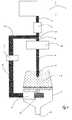
- the schematic device on figures 1 and 2consists of a water inlet pipe 3 successively connecting a tank 1 , a pump 2 , a heater 15 and a water injection member 9 having a sufficiently sharp end to perforate a capsule 8 disposed on a capsule holder 7 in the extension of the water inlet pipe 3.
- the capsule holder 7has in its lower part an outlet orifice 10 .
- the upper part of the capsule holdercomprises perforating elements 13 , movable in a vertical direction. Once the bottom of the capsule 8 pierced by the perforating elements 13 , a water-coffee mixture can flow through the capsule holder 7 so as to be recovered in a cup (not shown) disposed under the orifice of exit 10 .
- the devicealso comprises a bypass line 5 whose upper end is connected to the water inlet pipe 3, between the pump 2 and the heating element 15 , by means of a Y-connection 11 :
- Conduit bypass 5also includes a valve 4 adapted to open from a predefined pressure.
- the lower end of the bypass line 5is connected to hydraulic activation means 6 , for example a piston, which, when activated following the opening of the valve 4 , cause the piercing elements 13 upwards towards capsule 8 .
- the deviceoperates as follows: Initially, the valve 4 is closed and the pump 2 inactivated. A new capsule 8 is placed on the capsule holder 7 , followed by the piercing of its upper wall by the injection member 9 . Water is then introduced into the inlet pipe 3 by activation of the pump 2 . See it figure 1 which represents in black the portions of pipe occupied by water following the activation of the pump 2.
- the valve 4When the water which is in the water inlet pipe 3 , thus in the capsule 8, has reached a preset pressure, the valve 4 opens so that the water flows into the rest of the water. bypass line 2 and activates the piercing elements 13 which pierce the bottom wall of the capsule 8 (see figure 2 ).
- the water-coffee mixture contained in the capsule 8flows through the cartridge-holder 7 , through orifices (not illustrated) and is recovered in a cup placed under the outlet orifice 10 .
- the capsule holderis not necessarily disposed below the capsule.
- the perforating elementscan pierce the capsule laterally or over it.
- the Figures 5 and 6represent a valve 4 that can be used with the device according to the invention.
- the valve 4comprises an inlet port 16 connected to the water inlet pipe 3, an outlet orifice 17 connected to the hydraulic means 6 , 12 , 13 , the two orifices being connected by a zone closure 18 through which a shutter piston 25 can be housed.
- the shutter pistonIn the rest position, the shutter piston is confined in the closing zone 18 by means of a spring 19 .
- the valve 4remains closed.
- the valve 4opens and the water exits through the outlet orifice 17 .
- the force exerted by the springcan be adjusted by the user of the device.
- the usercan therefore prepare his coffee according to his tastes.
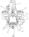
- the actuating mechanism of the perforating elements 13comprises the following parts: A flexible material reservoir 20, of annular shape, connected to the bypass line 5 (not shown), a mobile annular body 21 surrounding the capsule 8 and whose upper part rests on the reservoir 20 , a support plate 24 of perforating elements 13 connected to the annular body 21 by a fixing ring 22 .
- the support 23 of the capsule holder 7comprises a set of orifices through which the perforating elements can move.
- the actuating mechanism of the piercing elements 13operates as follows: In the rest position ( figure 7 ), the perforating elements are arranged under the bottom wall of the capsule 8 . In active mode ( figure 8 ), the water enters the tank 20 . The latter inflates and drives upwardly the movable annular body 21 and the assembly that is integral therewith, namely the fixing ring 22 , the support plate 24 and the perforating elements 13 . The bottom wall of the capsule is then perforated, which causes the flow of the water-coffee mixture through the outlet orifice 10 .
- the inventionis not limited to the examples described above.
- the Y connectionmay also be between the heating body and the injection member.
- the use of a flexible tank as described abovewould be particularly advantageous. This could be easily replaced in case of formation of limestone in the branch circuit.
Landscapes
- Engineering & Computer Science (AREA)
- Food Science & Technology (AREA)
- Mechanical Engineering (AREA)
- Apparatus For Making Beverages (AREA)
- Medicines Containing Material From Animals Or Micro-Organisms (AREA)
- Pharmaceuticals Containing Other Organic And Inorganic Compounds (AREA)
- Tea And Coffee (AREA)
Abstract
Description
Translated fromFrenchLa présente invention se situe dans le domaine des dispositifs pour la préparation de boissons à base de café par extraction d'une dose de café moulu contenue dans une capsule.The present invention is in the field of devices for the preparation of coffee-based beverages by extracting a dose of ground coffee contained in a capsule.
Des dispositifs fonctionnant selon le principe précité existent depuis de nombreuses décennies.Devices operating according to the aforementioned principle have existed for many decades.
Les brevets
La capsule décrite dans le brevet
Dans le dispositif présenté dans le brevet
D'autres dispositifs utilisant un mode de fonctionnement identique ou similaire à ceux précédemment décrits sont présentés dans les documents brevets suivants:
On connaît également d'autres dispositifs où le mélange eau-café est d'abord réalisé dans la chambre qui contient la capsule, mais s'écoule seulement à partir du moment où la pression dans la chambre qui contient la capsule a atteint une valeur minimale prédéfinie. Voir notamment les demandes de brevet
Dans tous les dispositifs cités plus haut, l'écoulement du mélange eau-café se déclenche à partir d'une pression déterminée, prédéfinie lors de la fabrication du dispositif.In all the devices mentioned above, the flow of the water-coffee mixture is triggered from a predetermined pressure, predefined during the manufacture of the device.
La demande de brevet
La dose de café est contenue dans une chambre qui s'ouvre et se referme en fonction de la pression hydraulique régnant dans une chambre spécifique.The dose of coffee is contained in a chamber that opens and closes depending on the hydraulic pressure prevailing in a specific chamber.
Le circuit comprend plusieurs valves dont une, sensible à la pression, qui fonctionne de manière à activer un sous-circuit de blocage de l'écoulement du mélange eau-café lorsque la pression de l'eau dans le circuit est trop base et, lorsque la pression est suffisante, de manière à activer un sous-circuit d'écoulement du mélange eau-café liquide.The circuit comprises a plurality of valves, one of which is pressure sensitive, which operates to activate a flow-blocking sub-circuit of the water-coffee mixture when the pressure of the water in the circuit is too much and, when the pressure is sufficient so as to activate a flow sub-circuit of the liquid water-coffee mixture.
Le dispositif précité est relativement complexe dans sa structure et son fonctionnement. En outre, il est adapté pour un type spécifique de doses de café et n'est pas destiné à des porte-capsules que l'on fixe ou retire manuellement du dispositif.The aforementioned device is relatively complex in its structure and operation. In addition, it is suitable for a specific type of coffee dose and is not intended for capsule holders that are manually fixed or removed from the device.
La présente vise notamment à remédier aux problèmes précités.The present aims in particular to remedy the aforementioned problems.
A cet effet, elle concerne un dispositif pour la préparation d'une boisson à base de café par extraction d'une dose de café moulu contenue dans une capsule tel que défini dans la revendication 1.For this purpose, it relates to a device for the preparation of a coffee-based beverage by extracting a dose of ground coffee contained in a capsule as defined in claim 1.
Il convient de noter que le dispositif selon l'invention présente de nombreuses différences et avantages par rapport à l'état de la technique. La demande
- fermeture hydraulique de la chambre qui retient la capsule,
- complexité de l'ensemble du dispositif (pluralité de valves et de lignes de conduite d'eau, etc...),
- disposition et fonctionnement de la valve sensible à la pression,
- absence d'organes de perforation de la caspule, mobiles par rapport au porte-capsule.
- hydraulic closing of the chamber which holds the capsule,
- complexity of the whole device (plurality of valves and lines of water, etc ...),
- arrangement and operation of the pressure sensitive valve,
- absence of perforation members of the caspule, movable relative to the capsule-holder.
De préférence, le dispositif comporte des moyens qui permette à l'utilisateur de choisir la pression d'ouverture de la valve, donc de définir la pression d'extraction du café de la capsule.Preferably, the device comprises means which allows the user to choose the opening pressure of the valve, thus to define the coffee extraction pressure of the capsule.
La valve est sensible à la pression, p.ex. mécaniquement, ce qui permet de simplifier considérablement le dispositif.The valve is pressure sensitive, eg mechanically, which greatly simplifies the device.
Selon une variante de l'invention, les moyens hydrauliques comprennent un obturateur qui alternativement obture ou autorise l'écoulement d'un mélange eau-café à travers l'orifice d'écoulement.According to a variant of the invention, the hydraulic means comprise a shutter which alternately closes or allows the flow of a water-coffee mixture through the flow orifice.
L'obturateur peut se situer n'importe où entre la capsule et l'orifice d'écoulement. Selon un mode de réalisation, il se situe au-dessous du porte-capsule.The shutter can be anywhere between the capsule and the flow port. According to one embodiment, it is located below the capsule-holder.
Bien évidemment, le dispositif peut contenir plusieurs obturateurs si plusieurs orifices doivent être obturés.Obviously, the device can contain several shutters if several orifices must be closed.
De préférence, on utilise avec cette variante des éléments de perforation, par ex. des dents, qui sont disposés sur le porte-capsule de manière à ce que la capsule soit perforée lors de son insertion dans le dispositif.Preferably, perforation elements, e.g. teeth, which are arranged on the capsule-holder so that the capsule is perforated during insertion into the device.
Selon une autre variante de l'invention, les moyens hydrauliques sont constitués d'au moins un organe de perforation qui, lorsqu'il est activé, perfore une capsule disposée sur le porte capsule et autorise de la sorte l'écoulement d'un mélange eau-café à travers l'orifice d'écoulement.According to another variant of the invention, the hydraulic means consist of at least one perforating member which, when it is activated, perforates a capsule disposed on the capsule holder and thus allows the flow of a mixture water-coffee through the drain hole.
Avantageusement, le dispositif comprend plusieurs organes de perforation qui se déplacent entre une position de repos (càd lorsqu'il n'y a pas d'écoulement du mélange eau-café), située sous ou dans le porte-capsule, et une position active située au-dessus du porte-capsule. Ainsi, la capsule repose initialement sur une surface plane. Lorsque les moyens hydrauliques sont activés, les organes de perforation émergent de la surface plane et percent la capsule.Advantageously, the device comprises a plurality of perforating members which move between a rest position (ie when there is no flow of the water-coffee mixture), located under or in the capsule-holder, and an active position. located above the capsule holder. Thus, the capsule initially rests on a flat surface. When the hydraulic means are activated, the perforating members emerge from the flat surface and pierce the capsule.
Selon une autre variante de l'invention, le dispositif peut être utilisé avec une capsule qui comporte déjà des orifices recouverts d'une fine membrane. Le porte-capsule comprend une membrane en silicone fixée sur un ressort qui obture initialement lesdits orifices mais qui les libère suite à l'application d'une force qui comprime le ressort.According to another variant of the invention, the device can be used with a capsule which already has orifices covered with a thin membrane. The capsule holder comprises a silicone membrane fixed on a spring which initially closes said orifices but which releases them following the application of a force which compresses the spring.
Selon une autre variante de l'invention, le porte-capsule contient un orifice d'écoulement de diamètre relativement large, les bords de l'orifice comportant au moins un élément d'amorce dont la fonction consiste à déchirer la membrane d'une capsule qui se bombe. L'orifice d'écoulement est initialement fermé par un piston et s'ouvre ensuite par déplacement du piston vers le bas.According to another variant of the invention, the capsule-holder contains a flow orifice of relatively large diameter, the edges of the orifice comprising at least one primer element whose function is to tear the membrane of a capsule who bombs himself. The flow port is initially closed by a piston and then opens by moving the piston down.
Il va sans dire que le dispositif selon l'invention peut être utilisé avec un très grand nombre de capsules différentes, qui comporte notamment une membrane qui se bombe ou ne se bombe pas suite à l'introduction d'eau dans la capsule.It goes without saying that the device according to the invention can be used with a very large number of different capsules, which includes a membrane that bombs or does not bomb following the introduction of water into the capsule.
De même, le dispositif selon l'invention, sans sa variante qui comprend des organes de perforation, peut utiliser des capsules avec des parois rigides, c'est-à-dire sans membrane flexible.Similarly, the device according to the invention, without its variant which comprises perforating members, can use capsules with rigid walls, that is to say without flexible membrane.
On relèvera également que les capsules utilisées peuvent être de formes diverses, p.ex. conique, cylindrique ou même cubique.It will also be noted that the capsules used may be of various shapes, eg conical, cylindrical or even cubic.
Quelques modes de réalisation de l'invention sont décrits ci-après au moyens des figures suivantes :
- La
figure 1 présente schématiquement une première variante de l'invention en mode de repos. - La
figure 2 présente la variante de lafigure 1 en mode actif. - La
figure 3 présente schématiquement une deuxième variante de l'invention en mode de repos. - La
figure 4 présente la variante de lafigure 3 en mode actif. - La
figure 5 montre une valve en position fermée. - La
figure 6 montre la valve de lafigure 5 en position ouverte. - La
figure 7 montre une coupe frontale d'un mode de réalisation du dispositif selon l'invention en mode de repos. - La
figure 8 montre une coupe frontale d'un mode de réalisation du dispositif selon l'invention en mode actif.
- The
figure 1 schematically presents a first variant of the invention in idle mode. - The
figure 2 presents the variant of thefigure 1 in active mode. - The
figure 3 schematically shows a second variant of the invention in idle mode. - The
figure 4 presents the variant of thefigure 3 in active mode. - The
figure 5 shows a valve in the closed position. - The
figure 6 shows the valve of thefigure 5 in open position. - The
figure 7 shows a frontal section of an embodiment of the device according to the invention in idle mode. - The
figure 8 shows a frontal section of an embodiment of the device according to the invention in active mode.
- 1. Réservoir1. Tank
- 2. Pompe2. Pump
- 3. Conduite d'arrivée d'eau3. Water supply line
- 4. Valve4. Valve
- 5. Conduite de dérivation5. Bypassing
- 6. Moyens hydrauliques d'activation6. Hydraulic means of activation
- 7. Porte-capsule7. Capsule holder
- 8. Capsule8. Capsule
- 9. Organe d'injection d'eau9. Injection body
- 10.Orifice de sortie10.Origration check
- 11. Raccord en Y11. Y-connection
- 12. Obturateur12. Shutter
- 13. Elément perforant13. Piercing element
- 14. Orifice d'écoulement14. Flow orifice
- 15. Corps de chauffe15. Heating body
- 16. Orifice d'entrée de valve16. Valve inlet port
- 17. Orifice de sortie de valve17. Valve outlet port
- 18.Zone de fermeture18.Zone of closure
- 19. Ressort19. Spring
- 20. Réservoir flexible20. Flexible tank
- 21. Corps annulaire mobile21. Mobile ring body
- 22. Bague de fixation22. Fixing ring
- 23. Support capsule23. Capsule support
- 24. Plaque support pour éléments perforants24. Support plate for piercing elements
- 25. Piston obturateur25. Shutter piston
Le dispositif schématisé sur les
La partie supérieure du porte-capsule comporte des éléments perforants13, mobiles selon une direction verticale. Une fois le fond de la capsule8 percé par les éléments perforants13, un mélange eau-café peut s'écouler à travers le porte-capsule7 de manière à être récupéré dans une tasse (non-illustrée) disposée sous l'orifice de sortie10.The upper part of the capsule holder comprises perforating
Le dispositif comprend également une conduite de dérivation5 dont l'extrémité supérieure est branchée sur la conduite d'arrivée d'eau 3, entre la pompe2 et le corps de chauffe15, au moyen d'un raccord en Y11: La conduite de dérivation5 comprend aussi une valve4 adaptée pour s'ouvrir à partir d'une pression prédéfinie. Enfin, l'extrémité inférieure de la conduite de dérivation5 est connectée à des moyens hydrauliques d'activation6, par exemple un piston, qui, lorsqu'ils sont activés suite à l'ouverture de la valve4, entraînent les éléments perforants13 vers le haut en direction de la capsule8.The device also comprises a
Le dispositif fonctionne comme suit : Initialement, la valve4 est fermée et la pompe2 inactivée. On place une nouvelle capsule8 sur le porte-capsule7, suivi du percement de sa paroi supérieure par l'organe d'injection9. De l'eau est ensuite introduite dans la conduite d'arrivée 3 par activation de la pompe2. Voir la
Lorsque l'eau qui se trouve dans la conduite d'arrivée d'eau3, donc dans la capsule8, a atteint une pression prédéfinie, la valve4 s'ouvre de sorte que l'eau s'écoule dans le reste de la conduite de dérivation2 et active les éléments perforants13 qui percent la paroi inférieure de la capsule8 (voir
Il va de soi que les schémas illustrés sur les
La variante illustrée sur les
Les
Avantageusement, la force exercée par le ressort peut être réglée par l'utilisateur du dispositif. En variant la pression du mélange eau-café régnant dans la capsule, l'utilisateur a donc la possibilité de préparer son café selon ses goûts.Advantageously, the force exerted by the spring can be adjusted by the user of the device. By varying the pressure of the water-coffee mixture prevailing in the capsule, the user can therefore prepare his coffee according to his tastes.
Un mode de réalisation détaillé de la variante des
Le mécanisme d'actionnement des éléments perforants13 comprend les pièces suivantes : Un réservoir en matière flexible20, de forme annulaire, relié à la conduite de dérivation5 (non-illustrée), un corps annulaire mobile21 entourant la capsule8 et dont la partie supérieure repose sur le réservoir20, une plaque support24 d'éléments perforants13 reliée au corps annulaire21 par une bague de fixation22. Le support23 du porte-capsule 7 comporte un ensemble d'orifices au travers desquels les éléments perforants peuvent se mouvoir.The actuating mechanism of the perforating
Le mécanisme d'actionnement des éléments perforants13 fonctionne comme suit : En position de repos (
Il va de soi que l'invention ne se limite pas aux exemples décrits précédemment. Par exemple, le raccord en Y peut également se situer entre le corps de chauffe et l'organe d'injection. Avec cette configuration, l'utilisation d'un réservoir flexible tel que décrit plus haut serait particulièrement avantageuse. Celui-ci pourrait être remplacé aisément en cas de formation de calcaire dans le circuit de dérivation.It goes without saying that the invention is not limited to the examples described above. For example, the Y connection may also be between the heating body and the injection member. With this configuration, the use of a flexible tank as described above would be particularly advantageous. This could be easily replaced in case of formation of limestone in the branch circuit.
Claims (7)
- Device for the preparation of a coffee-based drink by extracting a dose of ground coffee contained in a capsule (8), said device comprising a water tank (1), a pump (2), a heater body (15) and a water injection member (9) connected successively via a water inlet pipe (3); the device also comprising, disposed in the extension of the water injection member (9), a capsule-carrier (7) and an outlet orifice (10) for the water-coffee mixture, the capsule-carrier (7) being suitable for being manually attached to and removed from the device and comprising means for containing a capsule (8) of coffee, so that the pressurized water originating from the water injection member (9) can pass through the capsule (8) and pass through the outlet orifice (10), said device beingcharacterized in that it also consists of a single branch pipe (5), said branch pipe (5) being connected at one of its ends to the water inlet pipe (3), and comprises, at the other of its ends, hydraulic means (6, 12, 13, 20) suitable for controlling the outflow of a water-coffee mixture through the outlet orifice (10); the device also comprising a valve (4) placed on the branch pipe (5), said valve (4) being suitable either to be open and allow the water to flow into the branch pipe (5) when a preset pressure is reached, or closed and close off any flow in the branch pipe (5) when said preset pressure is not yet reached.
- Device according to the preceding claim, comprising means of adjustment, by a user, of said preset pressure.
- Device according to Claim 1 or 2,characterized in that the valve (4) is pressure-sensitive.
- Device according to any one of Claims 1 to 3,characterized in that the hydraulic means (6, 12) comprise a stopper (12) which alternatively closes off or releases the flow of a water-coffee mixture through the outlet orifice (10).
- Device according to the preceding claim,characterized in that the capsule-carrier (7) comprises at least one outflow orifice (14) and that the hydraulic means (6, 12) are placed so as to be able to close off said orifice (14).
- Device according to any one of Claims 1 to 3,characterized in that the hydraulic means (6, 13) consist of at least one perforation member (13) which, when it is activated, perforates a capsule (8) placed on the capsule-carrier (7) and thereby allows a water-coffee mixture to flow through the outlet orifice (10).
- Device according to any one of the preceding claims,characterized in that the hydraulic means comprise a flexible reservoir (20) which, when it swells following the arrival of water, operates means (21, 22, 24, 12, 13) which release the outflow of a water-coffee mixture through the outlet orifice (10).
Applications Claiming Priority (2)
| Application Number | Priority Date | Filing Date | Title |
|---|---|---|---|
| CH13532003 | 2003-08-05 | ||
| PCT/CH2004/000484WO2005011452A1 (en) | 2003-08-05 | 2004-08-03 | Device for the preparation of a coffee-based drink |
Publications (2)
| Publication Number | Publication Date |
|---|---|
| EP1653832A1 EP1653832A1 (en) | 2006-05-10 |
| EP1653832B1true EP1653832B1 (en) | 2008-10-08 |
Family
ID=34109556
Family Applications (1)
| Application Number | Title | Priority Date | Filing Date |
|---|---|---|---|
| EP04738124AExpired - LifetimeEP1653832B1 (en) | 2003-08-05 | 2004-08-03 | Device for the preparation of a coffee-based drink |
Country Status (8)
| Country | Link |
|---|---|
| US (1) | US7464636B2 (en) |
| EP (1) | EP1653832B1 (en) |
| JP (1) | JP4231079B2 (en) |
| CN (1) | CN100459915C (en) |
| AT (1) | ATE410102T1 (en) |
| DE (1) | DE602004017013D1 (en) |
| ES (1) | ES2315665T3 (en) |
| WO (1) | WO2005011452A1 (en) |
Cited By (5)
| Publication number | Priority date | Publication date | Assignee | Title |
|---|---|---|---|---|
| US9439532B2 (en) | 2014-03-11 | 2016-09-13 | Starbucks Corporation | Beverage production machines with multi-chambered basket units |
| US9504348B2 (en) | 2014-03-11 | 2016-11-29 | Starbucks Corporation | Cartridge ejection systems and methods for single-serve beverage production machines |
| US9968217B2 (en) | 2015-06-16 | 2018-05-15 | Starbucks Corporation | Beverage preparation systems with brew chamber securing mechanisms |
| US10342377B2 (en) | 2015-06-16 | 2019-07-09 | Starbucks Corporation | Beverage preparation systems with adaptable brew chambers |
| US10602874B2 (en) | 2015-06-16 | 2020-03-31 | Starbucks Corporation Dba Starbucks Coffee Company | Beverage preparation systems with brew chamber access mechanisms |
Families Citing this family (37)
| Publication number | Priority date | Publication date | Assignee | Title |
|---|---|---|---|---|
| NL1028134C2 (en)* | 2005-01-27 | 2006-07-31 | Sara Lee De Nv | Method for preparing a drink suitable for consumption from at least two ingredients to be dissolved and / or extracted and an amount of liquid. |
| US20070196402A1 (en)* | 2006-01-27 | 2007-08-23 | L'oreal | Method of preparing a cosmetic composition, and an assembly and a refill for implementing such a method |
| FR2896687B1 (en)* | 2006-01-27 | 2008-07-18 | Oreal | PROCESS FOR PREPARING A COSMETIC COMPOSITION AND APPARATUS FOR IMPLEMENTING SUCH A METHOD |
| GB2462392B (en)* | 2007-05-18 | 2010-08-18 | Kraft Foods R & D Inc | Beverage preparation machines and methods for operating beverage preparation machines |
| ES2432621T3 (en)* | 2008-09-13 | 2013-12-04 | Ethical Coffee Company Sa | Device for the preparation of a drink |
| PT104382A (en) | 2009-02-12 | 2010-08-12 | Briel Electrodomesticos | EXTRACTION DEVICE FOR AN INFUSION PRODUCTION MACHINE AND RESPECTIVE COUNTER-PRESSURE MECHANISM |
| ES2418329T3 (en)* | 2009-07-24 | 2013-08-13 | Ethical Coffee Company Sa | Device for preparing a beverage extracted from a capsule |
| ITMI20091633A1 (en)* | 2009-09-24 | 2011-03-25 | Brasilia Spa | START-UP DEVICE FOR AN AROMATIC DRINK PRODUCTION MACHINE |
| US8973488B2 (en) | 2009-10-05 | 2015-03-10 | Nestec S.A. | Cartridge extraction device |
| ITBG20090059A1 (en)* | 2009-11-09 | 2011-05-10 | Emmebielle S R L | UNIT AND METHOD FOR THE PRODUCTION OF INFUSED DRINKS, IN PARTICULAR COFFEE |
| CN102639037B (en)* | 2009-12-01 | 2015-11-25 | 雀巢产品技术援助有限公司 | Cartridge extraction device |
| DE102009055385A1 (en) | 2009-12-29 | 2011-06-30 | BSH Bosch und Siemens Hausgeräte GmbH, 81739 | Process for brewing hot drinks and hot beverage preparation machine |
| WO2013163436A2 (en)* | 2012-04-25 | 2013-10-31 | Apiqe Inc | Beverage system with flavor pod dispenser |
| US20150125586A1 (en)* | 2010-05-03 | 2015-05-07 | Apiqe | Beverage system with flavor pod dispenser |
| CA2801176A1 (en)* | 2010-06-01 | 2011-12-08 | Oded Loebl | Coffee maker |
| PT2409609E (en)* | 2010-07-22 | 2013-01-07 | Nestec Sa | A capsule holder or an adapter for adapting a capsule in a capsule holder in a beverage preparation machine |
| IT1402338B1 (en)* | 2010-10-13 | 2013-08-30 | Studio Polillo S A S Di Corrente A & C | CAPSULE CLOSING DEVICE FOR A CAPSULES COFFEE MACHINE. |
| BR112013011242A2 (en)* | 2010-11-11 | 2016-11-01 | Nestec S A Ch | capsule, beverage production machine and system for preparing a nutritional product |
| PT2462850E (en)* | 2010-12-13 | 2013-10-28 | Nestec Sa | A beverage preparation machine |
| KR101284552B1 (en)* | 2011-04-15 | 2013-07-11 | 주식회사 다인씨앤에프 | Extraction apparatus of beverage and method using the same |
| ITVE20110023A1 (en)* | 2011-04-19 | 2012-10-20 | Gherardo Viani | SINGLE-DOSE ICE CREAM |
| DE202011103272U1 (en)* | 2011-07-11 | 2012-02-09 | Eugster/Frismag Ag | Espresso coffee machine with a brewing unit |
| KR101450621B1 (en)* | 2013-01-08 | 2014-10-15 | 권혁표 | Coffee machine |
| NL2011917C2 (en)* | 2013-02-20 | 2014-12-18 | At Venture B V | SYSTEM FOR PREPARING A DRINK AND METHOD FOR THIS. |
| CN103417114B (en)* | 2013-07-31 | 2016-03-16 | 广东新宝电器股份有限公司 | Beverage machine and using method thereof |
| US20150257586A1 (en)* | 2014-03-11 | 2015-09-17 | Starbucks Corporation Dba Starbucks Coffee Company | Single-serve beverage production machine |
| ES2570877B1 (en)* | 2014-11-17 | 2017-03-03 | Bonesil Expansion, S.L. | Procedure of elaboration and conservation of olive paste |
| US9346611B1 (en) | 2015-03-20 | 2016-05-24 | Meltz, LLC | Apparatus and processes for creating a consumable liquid food or beverage product from frozen contents |
| US9487348B2 (en) | 2015-03-20 | 2016-11-08 | Meltz, LLC | Systems for and methods of providing support for displaceable frozen contents in beverage and food receptacles |
| US10314320B2 (en) | 2015-03-20 | 2019-06-11 | Meltz, LLC | Systems for controlled liquid food or beverage product creation |
| US10111554B2 (en) | 2015-03-20 | 2018-10-30 | Meltz, LLC | Systems for and methods of controlled liquid food or beverage product creation |
| EP3143911A1 (en)* | 2015-09-17 | 2017-03-22 | Mocoffee AG | Apparatus for producing a beverage from a capsule |
| US11432674B2 (en)* | 2017-02-28 | 2022-09-06 | Societe Des Produits Nestle S.A. | Dispenser with parallel dispensing paths |
| WO2018200922A1 (en) | 2017-04-27 | 2018-11-01 | Meltz, LLC | Method for centrifugal extraction and apparatus suitable for carrying out this method |
| CN109588989A (en)* | 2017-09-30 | 2019-04-09 | 广东美的生活电器制造有限公司 | Beverage machine |
| JP2021517019A (en)* | 2018-03-14 | 2021-07-15 | ソシエテ・デ・プロデュイ・ネスレ・エス・アー | Beverage extraction unit for selectively providing different types of orifices in capsules for extracting beverages |
| US11724849B2 (en) | 2019-06-07 | 2023-08-15 | Cometeer, Inc. | Packaging and method for single serve beverage product |
Family Cites Families (16)
| Publication number | Priority date | Publication date | Assignee | Title |
|---|---|---|---|---|
| US2899886A (en) | 1959-08-18 | rodth | ||
| US2968560A (en) | 1959-02-06 | 1961-01-17 | Sealpak Corp | Infusion package for producing a coffee beverage |
| US3403617A (en) | 1967-11-20 | 1968-10-01 | Universal Oil Prod Co | Apparatus for piercing containers for use in beverage producing machines |
| US3607297A (en) | 1969-03-13 | 1971-09-21 | Osvaldo Fasano | Method for producing beverages |
| CH668545A5 (en) | 1986-06-27 | 1989-01-13 | Nestle Sa | METHOD FOR EXTRACTION OF CLOSED CARTRIDGES FOR THE PREPARATION OF BEVERAGES. |
| TW199884B (en) | 1991-05-08 | 1993-02-11 | Sociere Des Produits Nestle S A | |
| ES2080196T3 (en) | 1991-07-05 | 1996-02-01 | Nestle Sa | DEVICE FOR THE EXTRACTION OF CARTRIDGES. |
| US5327815A (en) | 1991-07-05 | 1994-07-12 | Nestec S.A. | Device for use in beverage extraction machines |
| CN2276305Y (en)* | 1996-11-12 | 1998-03-18 | 端木乐善 | Waterway control device for cold and boilng water apparatus |
| US6079315A (en)* | 1999-01-19 | 2000-06-27 | Keurig, Inc. | Beverage filter cartridge holder |
| NL1014817C2 (en)* | 2000-03-31 | 2001-10-02 | Jong Duke De | Coffee maker. |
| US6740345B2 (en)* | 2000-12-22 | 2004-05-25 | Edward Zhihua Cai | Beverage making cartridge |
| CH694265A5 (en)* | 2001-01-24 | 2004-10-29 | Monodor Sa | Water injection device for an apparatus for the preparation of a beverage from a capsule containing the product to be extracted. |
| EP1247480B1 (en)* | 2001-04-05 | 2005-07-13 | Mövenpick - Holding | Coffee extraction system |
| TWM269020U (en)* | 2001-10-09 | 2005-07-01 | Fianara Int Bv | Apparatus for preparing hot beverages |
| US6786134B2 (en)* | 2002-02-07 | 2004-09-07 | The Coca-Cola Company | Coffee and tea dispenser |
- 2004
- 2004-08-03EPEP04738124Apatent/EP1653832B1/ennot_activeExpired - Lifetime
- 2004-08-03USUS10/566,973patent/US7464636B2/ennot_activeExpired - Fee Related
- 2004-08-03WOPCT/CH2004/000484patent/WO2005011452A1/enactiveSearch and Examination
- 2004-08-03DEDE602004017013Tpatent/DE602004017013D1/ennot_activeExpired - Lifetime
- 2004-08-03ESES04738124Tpatent/ES2315665T3/ennot_activeExpired - Lifetime
- 2004-08-03CNCNB2004800223502Apatent/CN100459915C/ennot_activeExpired - Fee Related
- 2004-08-03JPJP2006522194Apatent/JP4231079B2/ennot_activeExpired - Fee Related
- 2004-08-03ATAT04738124Tpatent/ATE410102T1/enactive
Cited By (6)
| Publication number | Priority date | Publication date | Assignee | Title |
|---|---|---|---|---|
| US9439532B2 (en) | 2014-03-11 | 2016-09-13 | Starbucks Corporation | Beverage production machines with multi-chambered basket units |
| US9504348B2 (en) | 2014-03-11 | 2016-11-29 | Starbucks Corporation | Cartridge ejection systems and methods for single-serve beverage production machines |
| US9999315B2 (en) | 2014-03-11 | 2018-06-19 | Starbucks Corporation | Beverage production methods with multi chambered basket units |
| US9968217B2 (en) | 2015-06-16 | 2018-05-15 | Starbucks Corporation | Beverage preparation systems with brew chamber securing mechanisms |
| US10342377B2 (en) | 2015-06-16 | 2019-07-09 | Starbucks Corporation | Beverage preparation systems with adaptable brew chambers |
| US10602874B2 (en) | 2015-06-16 | 2020-03-31 | Starbucks Corporation Dba Starbucks Coffee Company | Beverage preparation systems with brew chamber access mechanisms |
Also Published As
| Publication number | Publication date |
|---|---|
| WO2005011452A1 (en) | 2005-02-10 |
| CN100459915C (en) | 2009-02-11 |
| US7464636B2 (en) | 2008-12-16 |
| HK1094664A1 (en) | 2007-04-04 |
| EP1653832A1 (en) | 2006-05-10 |
| ATE410102T1 (en) | 2008-10-15 |
| JP2007501031A (en) | 2007-01-25 |
| CN1832697A (en) | 2006-09-13 |
| ES2315665T3 (en) | 2009-04-01 |
| DE602004017013D1 (en) | 2008-11-20 |
| JP4231079B2 (en) | 2009-02-25 |
| US20060196362A1 (en) | 2006-09-07 |
Similar Documents
| Publication | Publication Date | Title |
|---|---|---|
| EP1653832B1 (en) | Device for the preparation of a coffee-based drink | |
| EP2185446B1 (en) | Cartridge for preparing a beverage | |
| EP2348930B1 (en) | Device for preparing a drink | |
| EP2382143A1 (en) | Capsule for preparing a beverage, and device | |
| WO2010038213A2 (en) | Capsule for preparing a drink and device | |
| JP2007501031A6 (en) | Equipment for brewing coffee-based beverages | |
| EP1353591A1 (en) | Device for injecting water into an apparatus for preparing a beverage from a capsule | |
| WO2014097203A1 (en) | Capsule for preparing a beverage | |
| WO2000054694A1 (en) | Device for sealing the pulp cavity in a devitalized tooth | |
| CA2108453A1 (en) | Liquid dispensing container | |
| EP2005273B1 (en) | Pneumatic component for the controlled micro-diffusion of gas | |
| JP2008513085A (en) | Beverage preparation device having brew chamber and pressure release means | |
| BE1017480A3 (en) | AUTONOMOUS INFUSION APPARATUS. | |
| WO2014053779A1 (en) | Device for diffusing a product in water | |
| EP1605995A1 (en) | Needleless injection device comprising means for regulating the gas pressure level in the combustion chamber | |
| EP0919170B1 (en) | Filter carrier for an espresso type coffee machine | |
| WO2014135334A1 (en) | Device for spraying liquid like champagne | |
| HK1094664B (en) | Device for the preparation of a coffee-based drink | |
| CH710204A2 (en) | Airbag cell inflation system for people. | |
| FR2830500A1 (en) | Braking system incorporates at least one filter to which is connected in parallel a flow passage which can be opened or closed in dependence of temperature controlled valve | |
| EP1458632A1 (en) | Fluid product dispenser | |
| FR2556571A1 (en) | RAPID SEPARATION CLOSURE FOR LIFE-SAVING SYSTEMS | |
| EP3511476A1 (en) | Flushing valve for rinsing toilet basins with large or small volume double key control | |
| BE540656A (en) | ||
| FR2833825A1 (en) | Coffee filter holder has infusion chamber with bottom opening for flow of coffee extract and filter with movable plate fastening filter acted on by spring |
Legal Events
| Date | Code | Title | Description |
|---|---|---|---|
| PUAI | Public reference made under article 153(3) epc to a published international application that has entered the european phase | Free format text:ORIGINAL CODE: 0009012 | |
| 17P | Request for examination filed | Effective date:20060217 | |
| AK | Designated contracting states | Kind code of ref document:A1 Designated state(s):AT BE BG CH CY CZ DE DK EE ES FI FR GB GR HU IE IT LI LU MC NL PL PT RO SE SI SK TR | |
| DAX | Request for extension of the european patent (deleted) | ||
| GRAP | Despatch of communication of intention to grant a patent | Free format text:ORIGINAL CODE: EPIDOSNIGR1 | |
| GRAS | Grant fee paid | Free format text:ORIGINAL CODE: EPIDOSNIGR3 | |
| GRAA | (expected) grant | Free format text:ORIGINAL CODE: 0009210 | |
| AK | Designated contracting states | Kind code of ref document:B1 Designated state(s):AT BE BG CH CY CZ DE DK EE ES FI FR GB GR HU IE IT LI LU MC NL PL PT RO SE SI SK TR | |
| REG | Reference to a national code | Ref country code:GB Ref legal event code:FG4D Free format text:NOT ENGLISH | |
| REG | Reference to a national code | Ref country code:CH Ref legal event code:EP | |
| REG | Reference to a national code | Ref country code:IE Ref legal event code:FG4D Free format text:LANGUAGE OF EP DOCUMENT: FRENCH | |
| REF | Corresponds to: | Ref document number:602004017013 Country of ref document:DE Date of ref document:20081120 Kind code of ref document:P | |
| REG | Reference to a national code | Ref country code:CH Ref legal event code:NV Representative=s name:ANDRE ROLAND S.A. | |
| PG25 | Lapsed in a contracting state [announced via postgrant information from national office to epo] | Ref country code:SI Free format text:LAPSE BECAUSE OF FAILURE TO SUBMIT A TRANSLATION OF THE DESCRIPTION OR TO PAY THE FEE WITHIN THE PRESCRIBED TIME-LIMIT Effective date:20081008 | |
| REG | Reference to a national code | Ref country code:ES Ref legal event code:FG2A Ref document number:2315665 Country of ref document:ES Kind code of ref document:T3 | |
| PG25 | Lapsed in a contracting state [announced via postgrant information from national office to epo] | Ref country code:BG Free format text:LAPSE BECAUSE OF FAILURE TO SUBMIT A TRANSLATION OF THE DESCRIPTION OR TO PAY THE FEE WITHIN THE PRESCRIBED TIME-LIMIT Effective date:20090108 | |
| PG25 | Lapsed in a contracting state [announced via postgrant information from national office to epo] | Ref country code:FI Free format text:LAPSE BECAUSE OF FAILURE TO SUBMIT A TRANSLATION OF THE DESCRIPTION OR TO PAY THE FEE WITHIN THE PRESCRIBED TIME-LIMIT Effective date:20081008 Ref country code:PL Free format text:LAPSE BECAUSE OF FAILURE TO SUBMIT A TRANSLATION OF THE DESCRIPTION OR TO PAY THE FEE WITHIN THE PRESCRIBED TIME-LIMIT Effective date:20081008 Ref country code:PT Free format text:LAPSE BECAUSE OF FAILURE TO SUBMIT A TRANSLATION OF THE DESCRIPTION OR TO PAY THE FEE WITHIN THE PRESCRIBED TIME-LIMIT Effective date:20090218 | |
| REG | Reference to a national code | Ref country code:IE Ref legal event code:FD4D | |
| PG25 | Lapsed in a contracting state [announced via postgrant information from national office to epo] | Ref country code:DK Free format text:LAPSE BECAUSE OF FAILURE TO SUBMIT A TRANSLATION OF THE DESCRIPTION OR TO PAY THE FEE WITHIN THE PRESCRIBED TIME-LIMIT Effective date:20081008 Ref country code:EE Free format text:LAPSE BECAUSE OF FAILURE TO SUBMIT A TRANSLATION OF THE DESCRIPTION OR TO PAY THE FEE WITHIN THE PRESCRIBED TIME-LIMIT Effective date:20081008 Ref country code:IE Free format text:LAPSE BECAUSE OF FAILURE TO SUBMIT A TRANSLATION OF THE DESCRIPTION OR TO PAY THE FEE WITHIN THE PRESCRIBED TIME-LIMIT Effective date:20081008 Ref country code:RO Free format text:LAPSE BECAUSE OF FAILURE TO SUBMIT A TRANSLATION OF THE DESCRIPTION OR TO PAY THE FEE WITHIN THE PRESCRIBED TIME-LIMIT Effective date:20081008 | |
| PLBE | No opposition filed within time limit | Free format text:ORIGINAL CODE: 0009261 | |
| STAA | Information on the status of an ep patent application or granted ep patent | Free format text:STATUS: NO OPPOSITION FILED WITHIN TIME LIMIT | |
| PG25 | Lapsed in a contracting state [announced via postgrant information from national office to epo] | Ref country code:SE Free format text:LAPSE BECAUSE OF FAILURE TO SUBMIT A TRANSLATION OF THE DESCRIPTION OR TO PAY THE FEE WITHIN THE PRESCRIBED TIME-LIMIT Effective date:20090108 Ref country code:CZ Free format text:LAPSE BECAUSE OF FAILURE TO SUBMIT A TRANSLATION OF THE DESCRIPTION OR TO PAY THE FEE WITHIN THE PRESCRIBED TIME-LIMIT Effective date:20081008 | |
| 26N | No opposition filed | Effective date:20090709 | |
| PG25 | Lapsed in a contracting state [announced via postgrant information from national office to epo] | Ref country code:SK Free format text:LAPSE BECAUSE OF FAILURE TO SUBMIT A TRANSLATION OF THE DESCRIPTION OR TO PAY THE FEE WITHIN THE PRESCRIBED TIME-LIMIT Effective date:20081008 | |
| PG25 | Lapsed in a contracting state [announced via postgrant information from national office to epo] | Ref country code:MC Free format text:LAPSE BECAUSE OF NON-PAYMENT OF DUE FEES Effective date:20090831 | |
| GBPC | Gb: european patent ceased through non-payment of renewal fee | Effective date:20090803 | |
| PG25 | Lapsed in a contracting state [announced via postgrant information from national office to epo] | Ref country code:GR Free format text:LAPSE BECAUSE OF FAILURE TO SUBMIT A TRANSLATION OF THE DESCRIPTION OR TO PAY THE FEE WITHIN THE PRESCRIBED TIME-LIMIT Effective date:20090109 | |
| PG25 | Lapsed in a contracting state [announced via postgrant information from national office to epo] | Ref country code:GB Free format text:LAPSE BECAUSE OF NON-PAYMENT OF DUE FEES Effective date:20090803 | |
| REG | Reference to a national code | Ref country code:CH Ref legal event code:PUE Owner name:PSR PROFITABLE STRATEGIC REDEPLOYMENT SARL Free format text:GAILLARD, JEAN-PAUL#MORATEL 14#1096 CULLY (CH) -TRANSFER TO- PSR PROFITABLE STRATEGIC REDEPLOYMENT SARL#C/O MULTIFIDUCIAIRE FRIBOURG S.A. RUE FAUCIGNY 5#1700 FRIBOURG (CH) | |
| REG | Reference to a national code | Ref country code:NL Ref legal event code:SD Effective date:20110217 | |
| PG25 | Lapsed in a contracting state [announced via postgrant information from national office to epo] | Ref country code:LU Free format text:LAPSE BECAUSE OF NON-PAYMENT OF DUE FEES Effective date:20090803 | |
| REG | Reference to a national code | Ref country code:FR Ref legal event code:TP | |
| REG | Reference to a national code | Ref country code:ES Ref legal event code:PC2A Owner name:PSR PROFITABLE STRATEGIC REDEPLOYMENT SARL Effective date:20110510 | |
| PG25 | Lapsed in a contracting state [announced via postgrant information from national office to epo] | Ref country code:HU Free format text:LAPSE BECAUSE OF FAILURE TO SUBMIT A TRANSLATION OF THE DESCRIPTION OR TO PAY THE FEE WITHIN THE PRESCRIBED TIME-LIMIT Effective date:20090409 | |
| PG25 | Lapsed in a contracting state [announced via postgrant information from national office to epo] | Ref country code:TR Free format text:LAPSE BECAUSE OF FAILURE TO SUBMIT A TRANSLATION OF THE DESCRIPTION OR TO PAY THE FEE WITHIN THE PRESCRIBED TIME-LIMIT Effective date:20081008 | |
| PG25 | Lapsed in a contracting state [announced via postgrant information from national office to epo] | Ref country code:CY Free format text:LAPSE BECAUSE OF FAILURE TO SUBMIT A TRANSLATION OF THE DESCRIPTION OR TO PAY THE FEE WITHIN THE PRESCRIBED TIME-LIMIT Effective date:20081008 | |
| REG | Reference to a national code | Ref country code:CH Ref legal event code:PCAR Free format text:ANDRE ROLAND S.A.;CASE POSTALE 5107;1002 LAUSANNE (CH) | |
| REG | Reference to a national code | Ref country code:FR Ref legal event code:PLFP Year of fee payment:12 | |
| REG | Reference to a national code | Ref country code:FR Ref legal event code:PLFP Year of fee payment:13 | |
| REG | Reference to a national code | Ref country code:FR Ref legal event code:PLFP Year of fee payment:14 | |
| REG | Reference to a national code | Ref country code:FR Ref legal event code:PLFP Year of fee payment:15 | |
| PGFP | Annual fee paid to national office [announced via postgrant information from national office to epo] | Ref country code:IT Payment date:20180830 Year of fee payment:15 Ref country code:FR Payment date:20180827 Year of fee payment:15 Ref country code:ES Payment date:20180921 Year of fee payment:15 Ref country code:DE Payment date:20180823 Year of fee payment:15 Ref country code:NL Payment date:20180821 Year of fee payment:15 | |
| PGFP | Annual fee paid to national office [announced via postgrant information from national office to epo] | Ref country code:CH Payment date:20180822 Year of fee payment:15 Ref country code:BE Payment date:20180821 Year of fee payment:15 Ref country code:AT Payment date:20180822 Year of fee payment:15 | |
| REG | Reference to a national code | Ref country code:DE Ref legal event code:R119 Ref document number:602004017013 Country of ref document:DE | |
| REG | Reference to a national code | Ref country code:NL Ref legal event code:MM Effective date:20190901 | |
| REG | Reference to a national code | Ref country code:AT Ref legal event code:MM01 Ref document number:410102 Country of ref document:AT Kind code of ref document:T Effective date:20190803 | |
| PG25 | Lapsed in a contracting state [announced via postgrant information from national office to epo] | Ref country code:AT Free format text:LAPSE BECAUSE OF NON-PAYMENT OF DUE FEES Effective date:20190803 | |
| PG25 | Lapsed in a contracting state [announced via postgrant information from national office to epo] | Ref country code:LI Free format text:LAPSE BECAUSE OF NON-PAYMENT OF DUE FEES Effective date:20190831 Ref country code:CH Free format text:LAPSE BECAUSE OF NON-PAYMENT OF DUE FEES Effective date:20190831 | |
| REG | Reference to a national code | Ref country code:BE Ref legal event code:MM Effective date:20190831 | |
| PG25 | Lapsed in a contracting state [announced via postgrant information from national office to epo] | Ref country code:FR Free format text:LAPSE BECAUSE OF NON-PAYMENT OF DUE FEES Effective date:20190831 Ref country code:DE Free format text:LAPSE BECAUSE OF NON-PAYMENT OF DUE FEES Effective date:20200303 Ref country code:NL Free format text:LAPSE BECAUSE OF NON-PAYMENT OF DUE FEES Effective date:20190901 | |
| PG25 | Lapsed in a contracting state [announced via postgrant information from national office to epo] | Ref country code:BE Free format text:LAPSE BECAUSE OF NON-PAYMENT OF DUE FEES Effective date:20190831 Ref country code:IT Free format text:LAPSE BECAUSE OF NON-PAYMENT OF DUE FEES Effective date:20190803 | |
| REG | Reference to a national code | Ref country code:ES Ref legal event code:FD2A Effective date:20210105 | |
| PG25 | Lapsed in a contracting state [announced via postgrant information from national office to epo] | Ref country code:ES Free format text:LAPSE BECAUSE OF NON-PAYMENT OF DUE FEES Effective date:20190804 |