EP1650545B1 - Multiple sensing system, device and method - Google Patents
Multiple sensing system, device and methodDownload PDFInfo
- Publication number
- EP1650545B1 EP1650545B1EP05013138AEP05013138AEP1650545B1EP 1650545 B1EP1650545 B1EP 1650545B1EP 05013138 AEP05013138 AEP 05013138AEP 05013138 AEP05013138 AEP 05013138AEP 1650545 B1EP1650545 B1EP 1650545B1
- Authority
- EP
- European Patent Office
- Prior art keywords
- sensors
- sensor
- response
- array
- analyte
- Prior art date
- Legal status (The legal status is an assumption and is not a legal conclusion. Google has not performed a legal analysis and makes no representation as to the accuracy of the status listed.)
- Expired - Lifetime
Links
- 238000000034methodMethods0.000titleclaimsdescription27
- 230000004044responseEffects0.000claimsabstractdescription52
- 239000012491analyteSubstances0.000claimsabstractdescription46
- 239000000126substanceSubstances0.000claimsabstractdescription44
- 238000012544monitoring processMethods0.000claimsabstractdescription17
- 230000005855radiationEffects0.000claimsdescription39
- 230000003287optical effectEffects0.000claimsdescription19
- 238000005516engineering processMethods0.000claimsdescription18
- 238000004891communicationMethods0.000claimsdescription13
- 238000012545processingMethods0.000claimsdescription13
- 229920000642polymerPolymers0.000claimsdescription11
- 229920001940conductive polymerPolymers0.000claimsdescription10
- 239000000835fiberSubstances0.000claimsdescription9
- 239000002322conducting polymerSubstances0.000claimsdescription8
- 230000005540biological transmissionEffects0.000claimsdescription6
- 238000000576coating methodMethods0.000claimsdescription6
- 239000013307optical fiberSubstances0.000claimsdescription5
- 238000003380quartz crystal microbalanceMethods0.000claimsdescription5
- 238000010897surface acoustic wave methodMethods0.000claimsdescription5
- 230000001953sensory effectEffects0.000claimsdescription4
- 239000007789gasSubstances0.000description54
- 238000001514detection methodMethods0.000description33
- 239000000523sampleSubstances0.000description30
- CURLTUGMZLYLDI-UHFFFAOYSA-NCarbon dioxideChemical compoundO=C=OCURLTUGMZLYLDI-UHFFFAOYSA-N0.000description17
- LFQSCWFLJHTTHZ-UHFFFAOYSA-NEthanolChemical compoundCCOLFQSCWFLJHTTHZ-UHFFFAOYSA-N0.000description16
- 238000004458analytical methodMethods0.000description15
- 238000003491arrayMethods0.000description15
- 230000009102absorptionEffects0.000description13
- 238000010521absorption reactionMethods0.000description13
- 230000002068genetic effectEffects0.000description10
- 210000001331noseAnatomy0.000description10
- 238000000513principal component analysisMethods0.000description10
- 229910002092carbon dioxideInorganic materials0.000description9
- 150000001875compoundsChemical class0.000description9
- 235000019645odorNutrition0.000description9
- 230000008569processEffects0.000description9
- 238000013528artificial neural networkMethods0.000description8
- 239000001569carbon dioxideSubstances0.000description8
- 239000011159matrix materialSubstances0.000description8
- 229910044991metal oxideInorganic materials0.000description8
- 150000004706metal oxidesChemical class0.000description8
- 239000000047productSubstances0.000description8
- 238000012360testing methodMethods0.000description7
- CSCPPACGZOOCGX-UHFFFAOYSA-NAcetoneChemical compoundCC(C)=OCSCPPACGZOOCGX-UHFFFAOYSA-N0.000description6
- OKKJLVBELUTLKV-UHFFFAOYSA-NMethanolChemical compoundOCOKKJLVBELUTLKV-UHFFFAOYSA-N0.000description6
- 238000010586diagramMethods0.000description6
- 239000012530fluidSubstances0.000description6
- 239000000203mixtureSubstances0.000description6
- 210000004027cellAnatomy0.000description5
- 238000006073displacement reactionMethods0.000description5
- 238000012986modificationMethods0.000description5
- 230000004048modificationEffects0.000description5
- 238000003909pattern recognitionMethods0.000description5
- 239000010453quartzSubstances0.000description5
- VYPSYNLAJGMNEJ-UHFFFAOYSA-Nsilicon dioxideInorganic materialsO=[Si]=OVYPSYNLAJGMNEJ-UHFFFAOYSA-N0.000description5
- 241000894007speciesSpecies0.000description5
- -1vaporsSubstances0.000description5
- 239000012855volatile organic compoundSubstances0.000description5
- 235000013305foodNutrition0.000description4
- 230000006870functionEffects0.000description4
- 229930195733hydrocarbonNatural products0.000description4
- 239000007788liquidSubstances0.000description4
- 239000003550markerSubstances0.000description4
- 238000005457optimizationMethods0.000description4
- 238000012372quality testingMethods0.000description4
- WSFSSNUMVMOOMR-UHFFFAOYSA-NFormaldehydeChemical compoundO=CWSFSSNUMVMOOMR-UHFFFAOYSA-N0.000description3
- YXFVVABEGXRONW-UHFFFAOYSA-NTolueneChemical compoundCC1=CC=CC=C1YXFVVABEGXRONW-UHFFFAOYSA-N0.000description3
- 229910052799carbonInorganic materials0.000description3
- 230000008859changeEffects0.000description3
- 239000004020conductorSubstances0.000description3
- 230000002596correlated effectEffects0.000description3
- 230000000875corresponding effectEffects0.000description3
- 239000013078crystalSubstances0.000description3
- 201000010099diseaseDiseases0.000description3
- 208000037265diseases, disorders, signs and symptomsDiseases0.000description3
- 231100001261hazardousToxicity0.000description3
- 150000002430hydrocarbonsChemical class0.000description3
- 238000004519manufacturing processMethods0.000description3
- 239000000463materialSubstances0.000description3
- 229910052751metalInorganic materials0.000description3
- 239000002184metalSubstances0.000description3
- VNWKTOKETHGBQD-UHFFFAOYSA-NmethaneChemical compoundCVNWKTOKETHGBQD-UHFFFAOYSA-N0.000description3
- 244000005700microbiomeSpecies0.000description3
- 230000010287polarizationEffects0.000description3
- 238000003908quality control methodMethods0.000description3
- 239000004065semiconductorSubstances0.000description3
- 239000007787solidSubstances0.000description3
- KDSNLYIMUZNERS-UHFFFAOYSA-N2-methylpropanamineChemical compoundCC(C)CNKDSNLYIMUZNERS-UHFFFAOYSA-N0.000description2
- QGZKDVFQNNGYKY-UHFFFAOYSA-NAmmoniaChemical compoundNQGZKDVFQNNGYKY-UHFFFAOYSA-N0.000description2
- 239000004215Carbon black (E152)Substances0.000description2
- UGFAIRIUMAVXCW-UHFFFAOYSA-NCarbon monoxideChemical compound[O+]#[C-]UGFAIRIUMAVXCW-UHFFFAOYSA-N0.000description2
- NTYJJOPFIAHURM-UHFFFAOYSA-NHistamineChemical compoundNCCC1=CN=CN1NTYJJOPFIAHURM-UHFFFAOYSA-N0.000description2
- KFZMGEQAYNKOFK-UHFFFAOYSA-NIsopropanolChemical compoundCC(C)OKFZMGEQAYNKOFK-UHFFFAOYSA-N0.000description2
- BAVYZALUXZFZLV-UHFFFAOYSA-NMethylamineChemical compoundNCBAVYZALUXZFZLV-UHFFFAOYSA-N0.000description2
- BHHGXPLMPWCGHP-UHFFFAOYSA-NPhenethylamineChemical compoundNCCC1=CC=CC=C1BHHGXPLMPWCGHP-UHFFFAOYSA-N0.000description2
- 230000001133accelerationEffects0.000description2
- 239000003570airSubstances0.000description2
- 150000001298alcoholsChemical class0.000description2
- 239000012080ambient airSubstances0.000description2
- 230000008901benefitEffects0.000description2
- 239000008280bloodSubstances0.000description2
- 210000004369bloodAnatomy0.000description2
- VHRGRCVQAFMJIZ-UHFFFAOYSA-NcadaverineChemical compoundNCCCCCNVHRGRCVQAFMJIZ-UHFFFAOYSA-N0.000description2
- 229910002091carbon monoxideInorganic materials0.000description2
- 230000003197catalytic effectEffects0.000description2
- 239000002131composite materialSubstances0.000description2
- 239000003814drugSubstances0.000description2
- 231100000613environmental toxicologyToxicity0.000description2
- 230000005669field effectEffects0.000description2
- 230000001976improved effectEffects0.000description2
- 208000015181infectious diseaseDiseases0.000description2
- 150000002576ketonesChemical class0.000description2
- 238000005259measurementMethods0.000description2
- KIDHWZJUCRJVML-UHFFFAOYSA-NputrescineChemical compoundNCCCCNKIDHWZJUCRJVML-UHFFFAOYSA-N0.000description2
- 238000002310reflectometryMethods0.000description2
- 238000005067remediationMethods0.000description2
- 238000000926separation methodMethods0.000description2
- 239000000779smokeSubstances0.000description2
- 239000007784solid electrolyteSubstances0.000description2
- 238000007619statistical methodMethods0.000description2
- 238000011282treatmentMethods0.000description2
- XLYOFNOQVPJJNP-UHFFFAOYSA-NwaterSubstancesOXLYOFNOQVPJJNP-UHFFFAOYSA-N0.000description2
- 230000036642wellbeingEffects0.000description2
- BSKHPKMHTQYZBB-UHFFFAOYSA-N2-methylpyridineChemical classCC1=CC=CC=N1BSKHPKMHTQYZBB-UHFFFAOYSA-N0.000description1
- 206010002091AnaesthesiaDiseases0.000description1
- 241001120493AreneSpecies0.000description1
- 208000035143Bacterial infectionDiseases0.000description1
- OKTJSMMVPCPJKN-UHFFFAOYSA-NCarbonChemical compound[C]OKTJSMMVPCPJKN-UHFFFAOYSA-N0.000description1
- 208000035473Communicable diseaseDiseases0.000description1
- 208000001836Firesetting BehaviorDiseases0.000description1
- 206010017533Fungal infectionDiseases0.000description1
- UFHFLCQGNIYNRP-UHFFFAOYSA-NHydrogenChemical compound[H][H]UFHFLCQGNIYNRP-UHFFFAOYSA-N0.000description1
- 208000031888MycosesDiseases0.000description1
- CTQNGGLPUBDAKN-UHFFFAOYSA-NO-XyleneChemical compoundCC1=CC=CC=C1CCTQNGGLPUBDAKN-UHFFFAOYSA-N0.000description1
- 208000030852Parasitic diseaseDiseases0.000description1
- 239000004793PolystyreneSubstances0.000description1
- 239000005700PutrescineSubstances0.000description1
- DZGWFCGJZKJUFP-UHFFFAOYSA-NTyramineNatural productsNCCC1=CC=C(O)C=C1DZGWFCGJZKJUFP-UHFFFAOYSA-N0.000description1
- 208000036142Viral infectionDiseases0.000description1
- IKHGUXGNUITLKF-XPULMUKRSA-NacetaldehydeChemical compound[14CH]([14CH3])=OIKHGUXGNUITLKF-XPULMUKRSA-N0.000description1
- 150000001299aldehydesChemical class0.000description1
- 150000001335aliphatic alkanesChemical class0.000description1
- 150000001336alkenesChemical class0.000description1
- 150000001345alkine derivativesChemical class0.000description1
- 229910021529ammoniaInorganic materials0.000description1
- 230000037005anaesthesiaEffects0.000description1
- 238000013459approachMethods0.000description1
- 235000019568aromasNutrition0.000description1
- 150000004945aromatic hydrocarbonsChemical class0.000description1
- QVGXLLKOCUKJST-UHFFFAOYSA-Natomic oxygenChemical compound[O]QVGXLLKOCUKJST-UHFFFAOYSA-N0.000description1
- 208000022362bacterial infectious diseaseDiseases0.000description1
- 235000013405beerNutrition0.000description1
- 235000013361beverageNutrition0.000description1
- 210000001124body fluidAnatomy0.000description1
- 239000010839body fluidSubstances0.000description1
- 238000009395breedingMethods0.000description1
- 230000001488breeding effectEffects0.000description1
- 239000006229carbon blackSubstances0.000description1
- 125000002915carbonyl groupChemical group[*:2]C([*:1])=O0.000description1
- 150000001735carboxylic acidsChemical class0.000description1
- 235000013351cheeseNutrition0.000description1
- 238000006243chemical reactionMethods0.000description1
- 239000007795chemical reaction productSubstances0.000description1
- 238000010224classification analysisMethods0.000description1
- 239000011248coating agentSubstances0.000description1
- 235000016213coffeeNutrition0.000description1
- 235000013353coffee beverageNutrition0.000description1
- 238000002485combustion reactionMethods0.000description1
- 238000012790confirmationMethods0.000description1
- 230000001276controlling effectEffects0.000description1
- 238000010411cookingMethods0.000description1
- 239000002537cosmeticSubstances0.000description1
- 230000007423decreaseEffects0.000description1
- 238000003745diagnosisMethods0.000description1
- 150000004985diaminesChemical class0.000description1
- 150000001993dienesChemical class0.000description1
- 235000014113dietary fatty acidsNutrition0.000description1
- 230000007613environmental effectEffects0.000description1
- 150000002170ethersChemical class0.000description1
- 238000011156evaluationMethods0.000description1
- 239000002360explosiveSubstances0.000description1
- 229930195729fatty acidNatural products0.000description1
- 239000000194fatty acidSubstances0.000description1
- 150000004665fatty acidsChemical class0.000description1
- 238000000855fermentationMethods0.000description1
- 230000004151fermentationEffects0.000description1
- 239000000796flavoring agentSubstances0.000description1
- 235000019634flavorsNutrition0.000description1
- 230000004907fluxEffects0.000description1
- 238000009472formulationMethods0.000description1
- 239000003205fragranceSubstances0.000description1
- 230000004345fruit ripeningEffects0.000description1
- 239000000446fuelSubstances0.000description1
- 239000002316fumigantSubstances0.000description1
- 230000002538fungal effectEffects0.000description1
- 239000003193general anesthetic agentSubstances0.000description1
- 239000002920hazardous wasteSubstances0.000description1
- 230000035876healingEffects0.000description1
- 230000036541healthEffects0.000description1
- 229960001340histamineDrugs0.000description1
- 239000001257hydrogenSubstances0.000description1
- 229910052739hydrogenInorganic materials0.000description1
- 238000003384imaging methodMethods0.000description1
- 150000002475indolesChemical class0.000description1
- 230000001939inductive effectEffects0.000description1
- 238000002329infrared spectrumMethods0.000description1
- 230000000977initiatory effectEffects0.000description1
- 238000003780insertionMethods0.000description1
- 230000037431insertionEffects0.000description1
- 238000007689inspectionMethods0.000description1
- 238000011835investigationMethods0.000description1
- 150000002500ionsChemical class0.000description1
- 150000002632lipidsChemical class0.000description1
- 210000004072lungAnatomy0.000description1
- 230000005415magnetizationEffects0.000description1
- 239000012528membraneSubstances0.000description1
- 239000002207metaboliteSubstances0.000description1
- 230000035772mutationEffects0.000description1
- 239000003345natural gasSubstances0.000description1
- 210000002569neuronAnatomy0.000description1
- 239000012811non-conductive materialSubstances0.000description1
- 230000003647oxidationEffects0.000description1
- 238000007254oxidation reactionMethods0.000description1
- 239000001301oxygenSubstances0.000description1
- 229910052760oxygenInorganic materials0.000description1
- 239000002304perfumeSubstances0.000description1
- 230000002093peripheral effectEffects0.000description1
- 230000035699permeabilityEffects0.000description1
- 229940117803phenethylamineDrugs0.000description1
- IEQIEDJGQAUEQZ-UHFFFAOYSA-NphthalocyanineChemical compoundN1C(N=C2C3=CC=CC=C3C(N=C3C4=CC=CC=C4C(=N4)N3)=N2)=C(C=CC=C2)C2=C1N=C1C2=CC=CC=C2C4=N1IEQIEDJGQAUEQZ-UHFFFAOYSA-N0.000description1
- 239000004033plasticSubstances0.000description1
- 229920003023plasticPolymers0.000description1
- 231100000614poisonToxicity0.000description1
- 230000007096poisonous effectEffects0.000description1
- 229920006254polymer filmPolymers0.000description1
- 229920002223polystyrenePolymers0.000description1
- 230000000644propagated effectEffects0.000description1
- 150000003222pyridinesChemical class0.000description1
- 238000011002quantificationMethods0.000description1
- 238000011084recoveryMethods0.000description1
- 239000003507refrigerantSubstances0.000description1
- 238000000611regression analysisMethods0.000description1
- 230000035945sensitivityEffects0.000description1
- 238000004513sizingMethods0.000description1
- ZFRKQXVRDFCRJG-UHFFFAOYSA-NskatoleChemical classC1=CC=C2C(C)=CNC2=C1ZFRKQXVRDFCRJG-UHFFFAOYSA-N0.000description1
- 230000000391smoking effectEffects0.000description1
- 239000002904solventSubstances0.000description1
- 230000003595spectral effectEffects0.000description1
- 230000001954sterilising effectEffects0.000description1
- 238000004659sterilization and disinfectionMethods0.000description1
- 235000000346sugarNutrition0.000description1
- 150000008163sugarsChemical class0.000description1
- 230000008093supporting effectEffects0.000description1
- 230000002123temporal effectEffects0.000description1
- 239000004753textileSubstances0.000description1
- 238000004861thermometryMethods0.000description1
- XOLBLPGZBRYERU-UHFFFAOYSA-Ntin dioxideChemical compoundO=[Sn]=OXOLBLPGZBRYERU-UHFFFAOYSA-N0.000description1
- 229910001887tin oxideInorganic materials0.000description1
- 238000012546transferMethods0.000description1
- 229960003732tyramineDrugs0.000description1
- DZGWFCGJZKJUFP-UHFFFAOYSA-OtyraminiumChemical compound[NH3+]CCC1=CC=C(O)C=C1DZGWFCGJZKJUFP-UHFFFAOYSA-O0.000description1
- 238000011144upstream manufacturingMethods0.000description1
- 238000009423ventilationMethods0.000description1
- 230000003612virological effectEffects0.000description1
- 230000000007visual effectEffects0.000description1
- 238000004832voltammetryMethods0.000description1
- 229910001868waterInorganic materials0.000description1
- 235000014101wineNutrition0.000description1
- 239000008096xyleneSubstances0.000description1
Images


Classifications
- B—PERFORMING OPERATIONS; TRANSPORTING
- B82—NANOTECHNOLOGY
- B82Y—SPECIFIC USES OR APPLICATIONS OF NANOSTRUCTURES; MEASUREMENT OR ANALYSIS OF NANOSTRUCTURES; MANUFACTURE OR TREATMENT OF NANOSTRUCTURES
- B82Y15/00—Nanotechnology for interacting, sensing or actuating, e.g. quantum dots as markers in protein assays or molecular motors
- G—PHYSICS
- G01—MEASURING; TESTING
- G01N—INVESTIGATING OR ANALYSING MATERIALS BY DETERMINING THEIR CHEMICAL OR PHYSICAL PROPERTIES
- G01N29/00—Investigating or analysing materials by the use of ultrasonic, sonic or infrasonic waves; Visualisation of the interior of objects by transmitting ultrasonic or sonic waves through the object
- G01N29/02—Analysing fluids
- G01N29/022—Fluid sensors based on microsensors, e.g. quartz crystal-microbalance [QCM], surface acoustic wave [SAW] devices, tuning forks, cantilevers, flexural plate wave [FPW] devices
- G—PHYSICS
- G01—MEASURING; TESTING
- G01N—INVESTIGATING OR ANALYSING MATERIALS BY DETERMINING THEIR CHEMICAL OR PHYSICAL PROPERTIES
- G01N33/00—Investigating or analysing materials by specific methods not covered by groups G01N1/00 - G01N31/00
- G01N33/0004—Gaseous mixtures, e.g. polluted air
- G01N33/0009—General constructional details of gas analysers, e.g. portable test equipment
- G01N33/0027—General constructional details of gas analysers, e.g. portable test equipment concerning the detector
- G01N33/0031—General constructional details of gas analysers, e.g. portable test equipment concerning the detector comprising two or more sensors, e.g. a sensor array
- G01N33/0032—General constructional details of gas analysers, e.g. portable test equipment concerning the detector comprising two or more sensors, e.g. a sensor array using two or more different physical functioning modes
- H—ELECTRICITY
- H04—ELECTRIC COMMUNICATION TECHNIQUE
- H04L—TRANSMISSION OF DIGITAL INFORMATION, e.g. TELEGRAPHIC COMMUNICATION
- H04L67/00—Network arrangements or protocols for supporting network services or applications
- H04L67/01—Protocols
- H04L67/12—Protocols specially adapted for proprietary or special-purpose networking environments, e.g. medical networks, sensor networks, networks in vehicles or remote metering networks
- H—ELECTRICITY
- H04—ELECTRIC COMMUNICATION TECHNIQUE
- H04L—TRANSMISSION OF DIGITAL INFORMATION, e.g. TELEGRAPHIC COMMUNICATION
- H04L9/00—Cryptographic mechanisms or cryptographic arrangements for secret or secure communications; Network security protocols
- H04L9/40—Network security protocols
- G—PHYSICS
- G01—MEASURING; TESTING
- G01N—INVESTIGATING OR ANALYSING MATERIALS BY DETERMINING THEIR CHEMICAL OR PHYSICAL PROPERTIES
- G01N1/00—Sampling; Preparing specimens for investigation
- G01N1/02—Devices for withdrawing samples
- G01N2001/021—Correlating sampling sites with geographical information, e.g. GPS
- G—PHYSICS
- G01—MEASURING; TESTING
- G01N—INVESTIGATING OR ANALYSING MATERIALS BY DETERMINING THEIR CHEMICAL OR PHYSICAL PROPERTIES
- G01N2291/00—Indexing codes associated with group G01N29/00
- G01N2291/02—Indexing codes associated with the analysed material
- G01N2291/021—Gases
- G01N2291/0215—Mixtures of three or more gases, e.g. air
- G—PHYSICS
- G01—MEASURING; TESTING
- G01N—INVESTIGATING OR ANALYSING MATERIALS BY DETERMINING THEIR CHEMICAL OR PHYSICAL PROPERTIES
- G01N2291/00—Indexing codes associated with group G01N29/00
- G01N2291/02—Indexing codes associated with the analysed material
- G01N2291/021—Gases
- G01N2291/0217—Smoke, combustion gases
- G—PHYSICS
- G01—MEASURING; TESTING
- G01N—INVESTIGATING OR ANALYSING MATERIALS BY DETERMINING THEIR CHEMICAL OR PHYSICAL PROPERTIES
- G01N2291/00—Indexing codes associated with group G01N29/00
- G01N2291/02—Indexing codes associated with the analysed material
- G01N2291/022—Liquids
- G01N2291/0224—Mixtures of three or more liquids
- G—PHYSICS
- G01—MEASURING; TESTING
- G01N—INVESTIGATING OR ANALYSING MATERIALS BY DETERMINING THEIR CHEMICAL OR PHYSICAL PROPERTIES
- G01N2291/00—Indexing codes associated with group G01N29/00
- G01N2291/02—Indexing codes associated with the analysed material
- G01N2291/022—Liquids
- G01N2291/0226—Oils, e.g. engine oils
- G—PHYSICS
- G01—MEASURING; TESTING
- G01N—INVESTIGATING OR ANALYSING MATERIALS BY DETERMINING THEIR CHEMICAL OR PHYSICAL PROPERTIES
- G01N2291/00—Indexing codes associated with group G01N29/00
- G01N2291/02—Indexing codes associated with the analysed material
- G01N2291/025—Change of phase or condition
- G01N2291/0256—Adsorption, desorption, surface mass change, e.g. on biosensors
- G—PHYSICS
- G01—MEASURING; TESTING
- G01N—INVESTIGATING OR ANALYSING MATERIALS BY DETERMINING THEIR CHEMICAL OR PHYSICAL PROPERTIES
- G01N2291/00—Indexing codes associated with group G01N29/00
- G01N2291/02—Indexing codes associated with the analysed material
- G01N2291/028—Material parameters
- G01N2291/02827—Elastic parameters, strength or force
- G—PHYSICS
- G01—MEASURING; TESTING
- G01N—INVESTIGATING OR ANALYSING MATERIALS BY DETERMINING THEIR CHEMICAL OR PHYSICAL PROPERTIES
- G01N2291/00—Indexing codes associated with group G01N29/00
- G01N2291/04—Wave modes and trajectories
- G01N2291/042—Wave modes
- G01N2291/0423—Surface waves, e.g. Rayleigh waves, Love waves
- G—PHYSICS
- G01—MEASURING; TESTING
- G01N—INVESTIGATING OR ANALYSING MATERIALS BY DETERMINING THEIR CHEMICAL OR PHYSICAL PROPERTIES
- G01N2291/00—Indexing codes associated with group G01N29/00
- G01N2291/04—Wave modes and trajectories
- G01N2291/042—Wave modes
- G01N2291/0426—Bulk waves, e.g. quartz crystal microbalance, torsional waves
- G—PHYSICS
- G01—MEASURING; TESTING
- G01N—INVESTIGATING OR ANALYSING MATERIALS BY DETERMINING THEIR CHEMICAL OR PHYSICAL PROPERTIES
- G01N2291/00—Indexing codes associated with group G01N29/00
- G01N2291/10—Number of transducers
- G01N2291/106—Number of transducers one or more transducer arrays
- H—ELECTRICITY
- H04—ELECTRIC COMMUNICATION TECHNIQUE
- H04L—TRANSMISSION OF DIGITAL INFORMATION, e.g. TELEGRAPHIC COMMUNICATION
- H04L69/00—Network arrangements, protocols or services independent of the application payload and not provided for in the other groups of this subclass
- H04L69/30—Definitions, standards or architectural aspects of layered protocol stacks
- H04L69/32—Architecture of open systems interconnection [OSI] 7-layer type protocol stacks, e.g. the interfaces between the data link level and the physical level
- H04L69/322—Intralayer communication protocols among peer entities or protocol data unit [PDU] definitions
- H04L69/329—Intralayer communication protocols among peer entities or protocol data unit [PDU] definitions in the application layer [OSI layer 7]
Definitions
- this inventionrelates to a multiple sensing modalities and, in particular, a system, device and method that comprises sensors capable of detecting a combination of chemical stimuli and physical stimuli.
- An electronic nose or artificial olfactory systemis a device that is capable of detecting a wide variety of analytes in fluids such as vapors, gases and liquids.
- the devicecomprises an array of sensors that in the presence of an analyte produces a response, such as an electrical response.
- the deviceproduces a unique signature output for a particular analyte.
- the output signaturecan be correlated and compared to a particular analyte or mixture of substances that are known. By comparing the unknown signature with the stored or known signatures the analyte can be identified.
- an electronic noseis sufficient to accurately determine the analyte of interest
- other physical data within the environment of the analytego undetected. These additional data can be used to identify the analyte.
- Physical parameters of the analyteinclude, but are not limited to, temperature, humidity, color, pH, solution concentration, wavelength absorption, taste, vapor pressure, mass, pressure, optical density, magnetic field, etc.
- the current state of the art breathalyzer used to determine the blood alcohol contentincludes an infrared detector (IR).
- IR detectorsare susceptible to interferences from other volatile organic compounds (VOC) which also absorb the IR, (see, Jones AW, J. Anal Tox. 20:522-527 (1996) ).
- VOCvolatile organic compounds
- Manufacturers of these evidentiary instrumentshave responded by adding additional channels in an effort to differentiate between the IR signature of ethanol and other volatile organic compounds.
- These volatile organic compoundsinclude acetone, toluene, xylene, methanol, isopropanol, and acetaldehyde, the list also includes water, carbon monoxide and carbon dioxide. Concentrations of the other analytes in the test gas are generally in the range of 0.01 to 0.10 mg/L. However, these modification are still ineffectual.
- Hybrid sensor systems containing different types of chemical sensorsare known.
- a system known as the MOSES systemexists wherein a modular system was used that included an array of different semiconducting gas sensors based on metal oxides, polymer coated quartz microbalance sensors, calorimetric sensors and electrochemical sensors.
- the MOSES systemoptionally contained a semiconductor field effect transistor sensor (MOSFET).
- MOSFETsemiconductor field effect transistor sensor
- the systemis limited to detecting odors using chemical sensors (see, H. Ulmer et al., Sensors and Actuators B, 43, 24-33 (1997) ).
- United States Patent No. 5,801,297which issued to Mifsud et al., on September 1, 1998, also discloses a hybrid chemical sensor system.
- This systemincludes a first enclosure having a first detection means wherein the first detection comprises a plurality of gas sensors using a same first technology selected from semiconductor gas sensors technology, conductive polymer gas sensors technology, or acoustic surface wave gas sensors technology.
- the systemalso includes a second enclosure having a second detection means.
- the second detection meansincludes a plurality of gas sensors using a same second technology selected from semiconductor gas sensors technology, conductive polymer gas sensors technology, or acoustic surface wave gas sensors technology. In this system, the second technology is different from the first technology.
- an electronic tonguein another hybrid sensor system, a combination of an electronic tongue and an electronic nose is described.
- the electronic noseconsisted of an array of gas sensors with pattern signal handling capability and sensor pattern recognition algorithms.
- the electronic tongueconsisted of taste analysis of liquids based upon pulsed voltammetry. (see, F. Winquist et al., Sensors and Actuators B 58, 512-217 (1999) .
- U.S. Patent No 5,832,411which is issued to Schatzmann, et al., on November 3, 1998, discloses a plurality of sensor units distributed over an area that communicate via a network with a central monitoring unit.
- the sensor unitsinclude sensor arrays that provide them with raw data in response to the presence of selected compounds in the ambient fluid.
- the raw sensor datais then processed to compute a local profile.
- the local profiles from the individual sensor unitsare then used to compute a spatial and temporal map for the compounds in the fluid. This map can then be used for a variety of purposes including tracking and predicting the flow of compounds through the area, identifying the source of compounds in the area, monitoring abatement, and controlling industrial processes.
- the present inventionprovides a distributed sensing system in a networked environment for identifying an analyte, the system comprising at least two sensors connected to the network comprising sensors capable of producing a first response in the presence of a chemical stimulus; a single sensor or array or array of sensors connected to the network comprising sensors capable of producing a second response in the presence of a physical stimulus; and a computer comprising a resident algorithm to process the responses and identify the analyte.
- the algorithmindicates or selects the most relevant sensor in the network to identify the analyte.
- the algorithmselects the most relevant sensor modality to use within each sensor array for a particular application.
- the sensorscan be separated over large spatial areas, wherein the sensor arrays are networked.
- Suitable networksinclude a computer local area network, an intranet or the Internet.
- Sensors capable of detecting a chemical stimuli and suitable for use in the present inventioninclude, but are not limited to, bulk conducting polymer films, semiconducting polymer sensors, surface acoustic wave devices, fiber optic micromirrors, quartz crystal microbalances, conducting/nonconducting regions sensors and dye impregnated polymeric coatings on optical fibers.
- the single sensorthe array of sensors of the present invention.
- These sensorsinclude, but are not limited to, optical sensors, mechanical sensors, radiation sensors, thermal sensors and combinations thereof.
- the physical stimulusis detected using an optical sensor.
- Optical stimulican be measured as wave amplitude, phase, polarization, wave velocity, refractive index, emissivity, reflectivity and absorption.
- the second sensor arraycomprises an IR sensor.
- the IR sensorcomprises an IR source to provide IR radiation through a gas sample contained in a sample cell for detection by a detector.
- the amplitude of the signal detected by the detector at a particular wavelengthwhich corresponds to the absorption wavelength of a gas of interest, provides an indication of the concentration of that gas in the sample.
- Various filterscan be used with the infrared sensors that are specific for various analytes. In order to detect ethanol for example, a 3.46 ⁇ m filter is used. If the analyte absorbs at this frequency, ethanol may be present. The absorption can then be confirmed using the sensors that detect the chemical stimulus.
- the present inventionrelates to a device for monitoring an analyte in an environment.
- the devicecomprises at least one sensor array, wherein the array of sensors comprises at least two sensors capable of producing a first response in the presence of a chemical stimulus; a second sensor capable of producing a second response in the presence of a physical stimulus; a connector that connects each of the sensors comprising the at least one sensor array and the second sensor to a central processing unit that collects and stores the first and the second responses; and an analyzer configured to analyze the first and second responses.
- the analyzermonitors the analytes in the environment.
- the term "monitor”refers to detection, identification, quantification, classification or combinations thereof.
- the second sensoris an array of sensors.
- the devicecan be a handheld device.
- chemical stimuliare detected using sensors that are disclosed in U.S. Patent No. 5,571,401 , which issued to Lewis et al., on November 5, 1996,
- the sensors described thereinare conducting materials and nonconducting materials arranged in a matrix of conducting and nonconducting regions.
- the nonconductive materialcan be a nonconducting polymer such as polystyrene.
- the conductive materialcan be a conducting polymer, carbon black, an inorganic conductor and the like.
- the sensor arrayscomprise at least two sensors, typically about 32 sensors, and in certain instances 1000 or more sensors.
- the present inventionprovides a method of for transferring a combination of chemical and physical data over a computer network for identification of an analyte.
- the methodincludes transmitting sensory data from a first sensor array comprising sensors capable of producing a first response in the presence of a chemical stimulus to a remote location; transmitting physical data from a second sensor array comprising sensors capable of producing a second response in the presence of a physical stimulus to a remote location; and processing the sensory and physical data at the remote location for identification of an analyte.
- the present systemcaptures additional stimuli that in traditional sensing systems goes undetected. This feature allows unparalleled detection and identification of analytes in an environment. By detecting additional stimuli in the environment, a more robust system is realized. In addition, because the system comprises multiple modalities of sensors, fewer incorrect identifications are made.
- the present inventionprovides a multiple sensing apparatus that is capable of responding to a variety of stimuli that is both chemical and physical in nature. By sensing both chemical and physical stimuli, a more accurate detection or identification of the environment and unknown analyte can be accomplished.
- the systems of the present inventioncan operate in a networked environment.
- Fig. 1represents one environment in which the systems of present invention can be used. This diagram is merely an illustration and should not limit the scope of the claims herein. One of ordinary skill in the art will recognize other variations, modifications, and alternatives.
- the distributed sensing system 100includes a network 109 such as, for example, the Internet.
- the distributed sensing system 100includes a first sensor array 108 connected to the network comprising sensors capable ofproducing a first response in the presence of a chemical stimulus; a second sensor array 112 connected to the network comprising sensors capable of producing a second response in the presence of a physical stimulus; and a computer 122 comprising a resident algorithm.
- the algorithmindicates or selects the most relevant sensor modality in the network to identify an analyte.
- the networkallows for communication of each of the sensors, such as a mobile sensor unit 125, to the central processing unit or computer.
- sensorssuch as a mobile sensor unit 125
- a number of different technologiescan be used to implement the communications between the first array of sensors 108, the second array of sensors 112, and the computer comprising a resident algorithm.
- the first and second sensor arrayincludes a communication interface that is capable of being coupled to the computer network 109.
- Suitable communication interfacesinclude, but are not limited to, an Ethernet interface, an RS-232 interface, a parallel port, a universal serial bus (USB), an infrared data link, an optical interface and a RF interface.
- the sensor arrayscan be hard wired directly to the network.
- the computer network 109can be one of a variety of networks including a worldwide computer network, an internet, the Internet, a WAN, a LAN or an intranet. It should be understood that access to the computer network is conducted through a gateway.
- a gatewayis a machine, for example, a computer that has a communication address recognizable by the computer network.
- the sensor arraycan communicate with the computer network 109 via the communication interface using either wireless 125 or wired technologies.
- Wireless technologiescan include infrared, radio waves, satellite and microwaves.
- the sensor arrayshave wireless Ethernet capabilities such as a radiocard having a media access controller.
- the media access controllerregulates the data from the sensor array to the network.
- the system of the present inventionincludes a first array of sensors wherein the sensors detect a chemical stimulus.
- Suitable chemical stimuli capable of detectioninclude, but are not limited to, analytes in fluids such as a vapor, a gas, a liquid, a solid, an odor or mixtures thereof.
- This aspect of the devicecomprises an electronic nose.
- Suitable sensors comprising the first array of sensorsinclude, but are not limited to, bulk conducting polymer films, semiconducting polymer sensors, surface acoustic wave devices, fiber optic micromirrors, quartz crystal microbalances, conducting/nonconducting regions sensors and dye impregnated polymeric coatings on optical fibers and combinations thereof.
- the electronic nosecomprises conducting/nonconducting regions sensors. It will be apparent to those of skill in the art that the electronic nose array can comprise combinations of the foregoing sensors.
- the present inventionrelates to a system that is capable of measuring or detecting both physical and chemical parameters. In this manner, a more robust and rigorous analysis of the environment can be accomplished with a more accurate determination of the identity of the unknown analyte.
- the systemcomprises a second array of sensors that are capable of detecting a wide range of physical stimuli. These sensors include, but are not limited to, optical sensors, mechanical sensors, radiation sensors, thermal sensors and combinations thereof.
- the physical stimulusis detected using an optical sensor.
- Optical stimulican be expressed as wave amplitude, phase, polarization, wave velocity, refractive index, emissivity, reflectivity and absorption.
- the second sensor arraycomprises an IR sensor.
- Concentration of gasessuch as CO, CO 2 , hydrocarbons (e.g. CH 4 ), carboxylic acids, microorganism off-gases or metabolites, ketones, alcohols, anesthetic agent gases, exhaust gases, Freon, or other gases can be determined by IR radiation.
- gasessuch as CO, CO 2 , hydrocarbons (e.g. CH 4 ), carboxylic acids, microorganism off-gases or metabolites, ketones, alcohols, anesthetic agent gases, exhaust gases, Freon, or other gases can be determined by IR radiation.
- Each species of gastypically has one or more distinct IR absorption characteristics and better absorbs IR radiation at or near a particular wavelength.
- the absorption of IR radiation at a frequency corresponding to a characteristic absorption wavelength of a particular gas speciesis directly related to the concentration of that species in the gas sample.
- the amplitude of the signal detected by the IR detector at a wavelength corresponding to a characteristic absorption wavelength of a particular gas speciesis
- the distributed sensing system 100can be used in many different applications.
- the sensor unitscan be distributed across an oil refinery to monitor the leakage of volatile gases into the atmosphere.
- a valve failurefor example, will be discovered immediately and a technician dispatched before it can present a serious safety hazard or seriously impact the operation of the refinery.
- the techniciancan have a handheld sensing device as described in WO 99/47905, published September 23, 1999 . At the scene of the leak, the technician can assess the amount and nature of the leak.
- the handheld devicecan communicate with the network via wireless mode.
- the systemcan also be used to monitor emission levels from industrial plants such as chemical or textile facilities.
- the data gatheredcan then be used to track and predict the progression of a plume of escaped dangerous or poisonous gas. In cases of an industrial incident, this information can be used to first warn downwind populations and later to estimate the impact of the incident on those environments.
- the sensor systemIn many industrial facilities, such as a nuclear facility, the sensor system can be used to monitor the perimeter. In incineration plants that produce dangerous compounds, the processes that are used to destroy compounds can be monitored.
- the system of the present inventioncan be used in myriad other applications in addition to the foregoing.
- applicationsinclude, but are not limited to, environmental toxicology and remediation, biomedicine, materials quality control, food and agricultural products monitoring.
- Further applicationsinclude: heavy industrial manufacturing (automotive, aircraft, etc.), such as ambient air monitoring, worker protection, emissions control, and product quality testing; oil/gas petrochemical applications, such as combustible gas detection, H 2 S monitoring, and hazardous leak detection and identification; emergency response and law enforcement applications, such as illegal substance detection and identification, arson investigation, hazardous spill identification, enclosed space surveying, and explosives detection; utility and power applications, such as emissions monitoring and transformer fault detection; food/beverage/agriculture applications, such as freshness detection, fruit ripening control, fermentation process monitoring and control, flavor composition and identification, product quality and identification, and refrigerant and fumigant detection.
- Additional applicationsinclude, but are not limited to, cosmetic/perfume applications, such as fragrance formulation, product quality testing, and fingerprinting; chemical/plastics/pharmaceuticals applications, such as fugitive emission identification, leak detection, solvent recovery effectiveness, perimeter monitoring, and product quality testing; hazardous waste site applications, such as fugitive emission detection and identification, leak detection and identification, transportation applications, such as hazardous spill monitoring, refueling operations, shipping container inspection, and diesel/gasoline/aviation fuel identification; building/residential applications, such as natural gas detection, formaldehyde detection, smoke detection, automatic ventilation control (cooking, smoking, etc.), and air intake monitoring; hospital/medical applications, such as anesthesia and sterilization gas detection, infectious disease detection, breath, wound and body fluids analysis, and telesurgey.
- cosmetic/perfume applicationssuch as fragrance formulation, product quality testing, and fingerprinting
- chemical/plastics/pharmaceuticals applicationssuch as fugitive emission identification, leak detection, solvent recovery effectiveness, perimeter monitoring, and product quality testing
- Terminal 122is connected to a server.
- This connectioncan be by a network such as Ethernet, asynchronous transfer mode, IEEE standard 1553 bus, modem connection, universal serial bus, etc.
- the communication linkneed not be a wire but can be infrared, radio wave transmission, etc.
- the serveris coupled to the Internet 109.
- the Internetis shown symbolically as a cloud or a collection of server routers 109.
- the connection to server to the Internetis typically by a relatively high bandwidth transmission medium such as a T1 or T3 line.
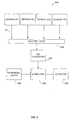
- Fig. 2represents one embodiment of a system of the present invention. This diagram is merely an illustration and should not limit the scope of the claims herein. One of ordinary skill in the art will recognize other variations, modifications, and alternatives.
- Fig. 2is a block diagram 200 of a system of the present invention.
- dataare collected from a patient from a number of sensor arrays 201, 203, 204 and 205.
- the sensor arrayscan be positioned directly on an object such as a hospital bed, or inside, or on the patient (such as a thermometer).
- sensor 201is a chemical sensor array for detecting the patient's breath. Using the breath sample, the patient's well being can be monitored.
- Sensor 203is a noncontact sensor, such as a video monitor.
- Sensor 204is an array of thermistors that are temperature sensitive resistors that monitors the patient's temperature (such as oral and anal cavities).
- Sensor 205is an optical sensor, such as an IR sensor that will allow more accurate identification of the patient's breath.
- the first and second sensor arrayincludes a communication interface 211 that is capable of being coupled to the computer network. Electrical signals from the sensors are thereafter fed into a multiplexer 225 that functions to connect the sensor arrays one at a time to an analog-to-digital (A/D) converter 230 or directly to a computer 235.
- the computer 235controls a multiplexer 225 and an A/D converter 230 for the appropriate timing.
- the computeris connected via the network to an array of actuators 253 that interact with various accessory devices.
- actuatorscan employ alarm signals, pneumatic valves for dispensing pharmaceuticals, etc.
- the systemoptionally comprises peripheral devices 262, including, but not limited to, a data recorder, a display, a monitor, etc.
- the system of the present inventionis more accurate at identifying an analyte than a single array alone. For instance, in the case of diabetics and persons who have abstained from food for a long period of time, acetone can appear in the blood and enter the alveoli of the lungs and eventually the breath. In addition, a person who has consumed ethanol will have ethanol present in their breath. Acetone and alcohol both have hydrocarbon absorptions, i.e., the 3.34 ⁇ m band in the infrared spectrum. However, when the IR sensors are used in conjunction with the chemical sensors, the chemical sensor array gives confirmation that the hydrocarbon present is either alcohol or ethanol. Thus, a tandem sensor array approach of detecting analytes gives a more accurate assessment of the analyte of interest.
- WO 98/29563published July 9, 1998 , discloses a method for monitoring conditions in a patient wherein a sample is obtained from a patient over a period of time. The samples are then flowed over a gas sensor and a response is measured. Thereafter, the response is correlated with known responses for known conditions.
- the conditionsinclude, but are not limited to, the progression and/or regression of a disease state, bacterial infections, viral, fungal or parasitic infections, the effectiveness of a course of treatment and the progress of a healing process.
- the system of the present inventioncan be used to monitor other medical conditions as set forth in WO 99/13786 , which published on December 23, 1999.
- volatile marker gasescharacterize the detection or diagnosis of a disease state or medical condition.
- the methods and apparatuscan advantageously by used to detect volatile marker gases and compounds indicative of medical conditions, disease processes, infections, illness and well-being. Using these marker gases and compounds, clinicians can use the diagnostic instruments and the systems, devices methods of the present invention to make diagnoses and formulate appropriate treatments.
- marker gasesinclude, but are not limited to, alkanes, alkenes, alkynes, dienes, alicyclic hydrocarbons, arenes, alcohols, ethers, ketones, aldehydes, carbonyls, carbanions, polynuclear aromatics, biomolecules, sugars, isoprenes isoprenoids, VOC, VOA, indoles, skatoles, diamines, pyridines, picolines, an off-gas of a microorganism, methylamine, isobutylamine, putrescine, cadaverine, histamine, tyramine, phenethylamine and fatty acids.
- the present inventionprovides a device for monitoring an analyte in an environment.
- the deviceincludes at least one sensor array, wherein the at least one sensor array comprises at least two sensors capable of producing a first response in the presence of a chemical stimulus; a second sensor which is capable of producing a second response in the presence of a physical stimulus; a connector that connects the at least one sensor array and the second sensor to a central processing unit, wherein the central processing unit collects and stores the first and second responses; and an analyzer configured to analyze a plurality of responses wherein the analyzer monitors said analyte in the environment.
- the deviceis a handheld device.
- the device of the present inventioncan be a handheld model such as that disclosed in WO 99/47905, published September 23, 1999 , and U.S. Patent Application No. 09/518,179, filed March 2, 2000 , or a desktop model device wherein the sensors array(s) are in close proximity to each other.
- the sensorscan be separated over larger spatial areas, wherein the sensor arrays are connected via a network, such as a computer local area network, or the Internet.
- a sensor chambercontains an array of chemical sensors and an infrared sensor array.
- a light sourceproduces a broad band radiation through a sample path.
- An analyte sourcesuch as human breath containing alcohol, is introduced in the sensor module.
- the chemical sensor arrayresponds with a signal, such as an electrical signal.
- the test sampleis directed through a sensor module 30 from an inlet port 31, through the sample chamber 32 and to an exhaust port 38.
- Sensor array devices 33such as a polymer composite, are arranged such that the test sample moves laterally across the exposed chemically sensitive sensors.
- Baffles 37are located at the trailing ends of each sensor array to assist in providing an efficient flow pattern.
- the IR source 39is centrally located and enters the sample chamber.
- IR filter(s) 34a, 34b, 34c, 34dare displaceable in the path of the IR beam. At least one IR sensor 36 is located beyond the filters. Another sensor is located in front of the filter (36a).
- a resonance amplifieris connected to the IR sensors, the resonance amplifier being a narrow-band amplifier that is arranged to be regulable.
- a filter member and a rectifierare connected to the output of the resonance amplifier.
- a second sensoris arranged in the path of the beam in front of the filter(s) and thus receives the unfiltered radiation emerging directly from the IR source. However, it must not be pushed into the path of the beam since it would otherwise mask the radiation.
- the second detectoris arranged in the range of reflection of the filter(s) and receives the unfiltered radiation reflected from the front side of the filter.
- Fig. 4shows a perspective view of an embodiment of a sensor module that includes four sensor devices mounted within two sample chambers 43.
- the sensor moduleis depicted as being configured for non-removable securement to a printed circuit board (PCB), but which alternatively could be configured as a plug-in module such as sensor module.
- the sensor moduleincorporates four plug-in sensor array devices 41, each including eight chemically sensitive sensors 53 ( Fig 5 ).
- Sensor modulecan include greater or fewer number of sensor array devices, and each sensor array device can include greater or fewer number of sensors.
- the four sensor array devices 41are mounted vertically in pairs on a board 46.
- a cover 47 having a pair of elongated recessesis secured over board 46 so as to define two separate sample chambers 43, one for each pair of sensor array devices 41.
- Sensor array devices 41are of similar shape and size, and each can be received in any one of the four connectors, or receptacles 42, formed in board 46.
- Fig. 5is a perspective view of one sensor array device 52.
- each sensor array device 52includes an array of eight chemically sensitive sensors 53, each providing a particular characteristic response when exposed to a test sample carrying analytes to be sensed.
- the sensorsare implemented using chemically sensitive resistors that provide particular resistances when exposed to a test sample.
- a multi-contact electrical connector 51is located along the lower edge of sensor array device 52 and is configured for insertion into one of four receptacles 42.
- Suitable sensor arrays of this kindare disclosed in U.S. Patent No. 5,575,401 , issued in the names of Nathan S. Lewis et al., entitled “Sensor Arrays for Detecting Analytes in Fluids" . Sensors disclosed in WO 99/27357, published June 6, 1999 , are also suitable for use in the present invention.
- Those of ordinary skill in the artwill appreciate that various alternative chemically sensitive sensors or devices could also be used.
- a radiation sourcein the form of a IR radiation source, located upstream of the radiation inlet, a filter, such as a filter having a pass band at 3.46 ⁇ m, a first IR sensor arranged beyond the filter, a second IR sensor arranged in the path of the beam beyond the radiation source of the sample chamber and in front of the filter, an amplifier connected to the output of the first sensor, a reference voltage source connected to the output of the second sensor, the outputs of the amplifier and the reference voltage source being connected to a differential amplifier.
- a filtersuch as a filter having a pass band at 3.46 ⁇ m
- a first IR sensorarranged beyond the filter
- a second IR sensorarranged in the path of the beam beyond the radiation source of the sample chamber and in front of the filter
- an amplifierconnected to the output of the first sensor
- a reference voltage sourceconnected to the output of the second sensor, the outputs of the amplifier and the reference voltage source being connected to a differential amplifier.
- the IR radiation sourcecan be a simple incandescent lamp in a quartz bulb.
- the radiationis split up into two portions beyond the radiation outlet of the sample chamber, one of which portions includes or supplies the measuring signal and the other portion acts as a control variable and a reference variable of the optical state of the measuring chamber. Operations are carried out simultaneously with both portions. Thus, errors do not occur which otherwise occur in arrangements wherein two different sample chambers or as a result of two successive measurements.
- the signal of the first detectoris fed to a resonance amplifier or signal amplifier.
- the signal of the second detectoris fed by way of an amplifier to a reference voltage source and controls the latter.
- the two voltages, that is the signal voltage and the reference voltageare subtracted and the difference is amplified in the differential amplifier.
- the reference voltage sourcemonitors, inter alia, the optical state of the measuring chamber and the radiation source.
- the voltage supplied by the reference voltage sourcechanges upon a change in the intensity of radiation.
- changes at the radiation outlet, not attributable to the analyte content of the vaporare removed from the measurement in that equal voltages appearing in the measuring and control path are subtracted from one another.
- Background airis introduced into the sample chamber in order to set up the apparatus.
- the second IR sensoris then set such that the signals in the two amplifiers are equal and the difference becomes zero. If the vapor containing the analyte is now introduced into the sample chamber, the intensity of the infrared radiation filtered out of the entire range by the filter is reduced by absorption by the analyte molecules, while the visible portion of the radiation reflected on the front face of the filter is not influenced by analyte and does not cause any change in the reference voltage.
- ⁇ e / ⁇ oe - mcd
- ⁇ ethe emerging current from the first IR sensor
- ⁇ othe entering current from the second IR sensor
- mis a constant of the analyte
- dis the path length
- cconcentration of the analyte
- the second detectoris arranged in the path of the beam in front of the filter and thus receives the unfiltered radiation emerging directly from the measuring chamber. However, it must not be pushed into the path of the beam since it would otherwise mask the radiation.
- the second detectoris arranged in the range of reflection of the filter and receives the unfiltered radiation reflected from the front side of the filter.
- the first array of sensorscomprise at least two sensors capable of producing a first response in the presence of a chemical stimulus.
- the second array of sensorscomprises at least two infrared sensors capable of producing a second response, such as in the presence of a physical stimulus; a connector that connects each of the sensors comprising the at least two sensor arrays to a central processing unit that collects and stores the first and the second responses; and an analyzer configured to analyze a plurality of responses from the at least two sensor arrays, wherein the analyzer monitors the analytes in the environment.
- Fig. 6shows a perspective view of an embodiment of yet another sensor module that includes a single sensor array device 60.
- sensor array device 60includes thirty two chemically sensitive sensors arranged in a two-dimensional grid and is mounted in a generally horizontal orientation on a socket 61.
- sensor array device 60can include greater or fewer number of sensors.
- the test sample being analyzedis directed from an inlet port 71 to a measuring chamber 75 and from there to where it passes across the chemically sensitive sensors 70.
- the test samplethen exits through an outlet port.
- various alternative chemically.sensitive sensors and devicescould also be used.
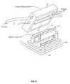
- Fig. 8illustrates a handheld device of the present invention.
- handheld device 80includes an elongated housing 81 having a lower end sized to be conveniently grasped and supported by the hand of an operator.
- a display 82 and several push-button control switches 83a through 83care located on the housing's topside, for convenient viewing and access by the operator.
- Push-button switches 83are used to control the device during its various operating modes.
- Display 82displays information about such operating modes and the results of the device's sensing.
- the identification of analyses and the determination of sample concentrationcan be performed by an "analyzer.”
- an analyzercan be a processor, a DSP processor, a specially designed ASIC, or other circuits designed to performed the analysis functions described herein.
- the analyzercan also be a general-purpose processor executing program codes written to perform the required analysis functions.
- the present inventionprovides sensor devices suitable for fire and smoke detection.
- the most effective way to detect fire initiationis to look for and detect end products of the oxidation process.
- These three elemental entitiescarbon, oxygen and hydrogen
- three compoundscarbon dioxide, carbon monoxide and water vapor
- carbon dioxide that is generated abundantly right from the start of the firecan easily be measured accurately using Non-Dispersive Infrared (NDIR) techniques of the present invention.
- NDIRNon-Dispersive Infrared
- the average ambient carbon dioxide concentration level of about 200 ppmdoes not hinder the detection of additional fire-induced quantities as long as the carbon dioxide sensor is designed to have such a fine sensitivity.
- radiation from a quasi-blackbody source that is pulsed electricallyis conducted through a gas sample chamber to a detector that is equipped with a single pass band filter whose pass band is located at a strong absorption band of carbon dioxide.
- the absorption band at 4.26 micronsis used.
- the detectorgenerates an electrical signal related to the intensity of the radiation falling on it. This signal decreases as the concentration of carbon dioxide in the sample chamber increases as the fire develops.
- An electronic circuit responsive to this signalproduces signals representative of the concentration of the carbon dioxide and representative of the rate of change of the concentration. These signals are compared with preset threshold levels and an alarm is generated in accordance with a built-in rule.
- the multiple sensing device of the present inventioncontains at least two sensor arrays.
- the first array of sensorscomprises at least two sensors capable of producing a first response in the presence of a chemical stimulus.
- Suitable chemical stimuli capable of detectioninclude, but are not limited to, a vapor, a gas, a liquid, a solid, an odor or mixtures thereof.
- Suitable sensors for the systems and devices of the present invention comprising the first array of sensorsinclude, but are not limited to, conducting/nonconducting regions sensor, a SAW sensor, a quartz microbalance sensor, a conductive composite sensor, a chemiresitor, a metal oxide gas sensor, an organic gas sensor, a MOSFET, a piezoelectric device, an infrared sensor, a sintered metal oxide sensor, a Pd-gate MOSFET, a metal FET structure, a electrochemical cell, a conducting polymer sensor, a catalytic gas sensor, an organic semiconducting gas sensor, a solid electrolyte gas sensors, and a piezoelectric quartz crystal sensor.
- the electronic nose arraycan be comprises of combinations of the foregoing sensors.
- a second sensorcan be a single sensor or an array of sensors capable of producing a second response in the presence of physical stimuli.
- the physical detection sensorsdetect physical stimuli. Suitable physical stimuli include, but are not limited to, thermal stimuli, radiation stimuli, mechanical stimuli, pressure, visual, magnetic stimuli, and electrical stimuli.
- Thermal sensorscan detect stimuli which include, but are not limited to, temperature, heat, heat flow, entropy, heat capacity, etc.
- Radiation sensorscan detect stimuli that include, but are not limited to, gamma rays, X-rays, ultra-violet rays, visible, infrared, microwaves and radio waves.
- Mechanical sensorscan detect stimuli which include, but are not limited to, displacement, velocity, acceleration, force, torque, pressure, mass, flow, acoustic wavelength, and amplitude.
- Magnetic sensorscan detect stimuli that include, but are not limited to, magnetic field, flux, magnetic moment, magnetization, and magnetic permeability.
- Electrical sensorscan detect stimuli which include, but are not limited to, charge, current, voltage, resistance, conductance, capacitance, inductance, dielectric permittivity, polarization and frequency.
- thermal sensorsare suitable for use in the present invention that include, but are not limited to, thermocouples, such as a semiconducting thermocouples, noise thermometry, thermoswitches, thermistors, metal thermoresistors, semiconducting thermoresistors, thermodiodes, thermotransistors, calorimeters, thermometers, indicators, and fiber optics.
- thermocouplessuch as a semiconducting thermocouples, noise thermometry, thermoswitches, thermistors, metal thermoresistors, semiconducting thermoresistors, thermodiodes, thermotransistors, calorimeters, thermometers, indicators, and fiber optics.
- various radiation sensorsare suitable for use in the present invention that include, but are not limited to, nuclear radiation microsensors, such as scintillation counters and solid state detectors, ultra-violet, visible and near infrared radiation microsensors, such as photoconductive cells, photodiodes, phototransistors, infrared radiation microsensors, such as photoconductive IR sensors and pyroelectric sensors.
- nuclear radiation microsensorssuch as scintillation counters and solid state detectors
- ultra-violetvisible and near infrared radiation microsensors
- visible and near infrared radiation microsensorssuch as photoconductive cells, photodiodes, phototransistors
- infrared radiation microsensorssuch as photoconductive IR sensors and pyroelectric sensors.
- Optical sensorsalso detect visible, near infrared and infrared waves.
- various mechanical sensorsare suitable for use in the present invention and include, but are not limited to, displacement microsensors, capacitive and inductive displacement sensors, optical displacement sensors, ultrasonic displacement sensors, pyroelectric, velocity and flow microsensors, transistor flow microsensors, acceleration microsensors, piezoresistive microaccelerometers, force, pressure and strain microsensors, and piezoelectric crystal sensors.
- various chemical or biochemical sensorsare suitable for use in the present invention and include, but are not limited to, metal oxide gas sensors, such as tin oxide gas sensors, organic gas sensors, chemocapacitors, chemoidiodes, such as inorganic Schottky device, metal oxide field effect transistor (MOSFET), piezoelectric devices, ion selective FET for pH sensors, polymeric humidity sensors, electrochemical cell sensors, pellistors gas sensors, piezoelectric or surface acoustical wave sensors, infrared sensors, surface plasmon sensors, and fiber optical sensors.
- metal oxide gas sensorssuch as tin oxide gas sensors, organic gas sensors, chemocapacitors, chemoidiodes, such as inorganic Schottky device, metal oxide field effect transistor (MOSFET), piezoelectric devices, ion selective FET for pH sensors, polymeric humidity sensors, electrochemical cell sensors, pellistors gas sensors, piezoelectric or surface acoustical wave sensors, infrared sensors, surface plasmon sensors, and
- sensors suitable for use in the present inventioninclude, but are not limited to, sintered metal oxide sensors, phthalocyanine sensors, membranes, Pd-gate MOSFET, electrochemical cells, conducting polymer sensors, lipid coating sensors and metal FET structures.
- the sensorsinclude, but are not limited to, metal oxide sensors such as a Tuguchi gas sensors, catalytic gas sensors, organic semiconducting gas sensors, solid electrolyte gas sensors, piezoelectric quartz crystal sensors, fiber optic probes, a micro-electro-mechanical system device, a micro-opto-electro-mechanical system device and Langmuir-Blodgett films.
- the present inventionincludes detection using sensors as disclosed in U.S. Patent No. 5,814,524 , which issued to Walt et al., on September 29, 1998.
- An optical detection and identification systemis disclosed therein that includes an optic sensor, an optic sensing apparatus and methodology for detecting and evaluating one or more analytes of interest, either alone or in mixtures.
- the systemis comprised of a supporting member and an array formed of heterogeneous, semi-selective polymer films which function as sensing receptor units and are able to detect a variety of different analytes using spectral recognition patterns. Using this system, it is possible to combine viewing and chemical sensing with imaging fiber chemical sensors.
- the system of the present inventioncomprises an optimization of sensor modalities algorithm.
- Fig. 9represents a flow diagram of the optimization algorithm whereby the sensor selection is made. This diagram is merely an illustration and should not limit the scope of the claims herein. One of ordinary skill in the art will recognize other variations, modifications, and alternatives.
- the system of the present inventionwill gather responses from sensors of different types and apply an appropriate sensor selection algorithm to determine optimal sensor types or modalities for a particular use or application.
- a genetic algorithmis used.
- the genetic algorithm of the present inventioncan be used for predictive variable selection with classification or regression models.
- the starting inputincludes a matrix of predictor variables (sensor responses) and a matrix of predicted variables (categorical or continuous variables).
- the outputis a population 990 that has passed the fitness convergence criteria embodied in the genetic algorithm.
- the fitness of the final members of the populationis provided and members of the final population contain 1's and 0's. As shown below, a 1 means a variable was included, and a 0 means that it was not included.
- the fitnessdepends on a variety of selection criteria. Suitable sensor selection criteria include, but are not limited to, the prediction error rate, the type of analyte to be detected, sensor availability, cost, power consumption, environmental conditions, polymer selection, etc. For instance, particular analytes are more responsive to particular polymer types e.g., ammonia and methanol are response to polypyrole. In addition, combustible gas analytes are easily detected with metal oxide sensors.
- the genetic algorithm of the present inventionaids in the determination of which type of sensor to use in a particular array for a particular application.
- the selection processcan be done during or after the sensing process or it can be an iterative selection process.
- the sensors of various modalities, types or kindsare more suitable for a particular application.
- the system of the present inventionwill gather responses from sensors of different types and apply appropriate sensor selection algorithms to determine optimal sensor types for a particular application.
- the genetic algorithmsare based on principles of natural evolution and selection.
- a random population of possible models (solutions) 910 or first generationis chosen first.
- a possible modelis produced in a binary form where 1 indicates inclusion of a sensor variable (or term derived from it) and 0 indicates that a sensor variable has not been included, e.g., members in a population can have the forms: 00111001011101........ 11101010011000........
- a classification or regression analysisis carried out for evaluation 920 and the prediction error rate is determined on which are based the fitness criteria 925.
- the modelsare then ranked based on the fitness criteria.
- the model forms with the lowest prediction errorare allowed to survive and breed. Pairs of these models are randomly selected for breeding using a crossover technique 940. New generations and mutations 945 are thus created.
- Fitness criteriaare again applied. The process continues until the maximum generations are allowed 950 before the algorithm quits and checks the final population 990.
- the algorithmcan also quit when the convergence criteria are reached 960.
- the outputis the final population 990 at either convergence 960 or at maximum generations allowed 950.
- the variablesi.e., sensors, which are present most in the final population, are the ones selected. Thus, by using the genetic algorithm of the present invention, the best sensor for the particular application can be ascertained.
- the extended compact genetic algorithm(ECGA) is used. Based on the analysis using this algorithm, empirical relations for population sizing and convergence time can be derived and are compared with the existing relations. After applying ECGA, an optimal sensor selection is obtained, with improved efficiency of sensor selection capabilities of the system.
- ECGAextended compact genetic algorithm
- Sensor/feature selectioncan include wavelength selection ( Lucasius, C.B.; Beckers, M.L.M.; Kateman, G., Anal. Chim. Acta 1994, 286, 135-153 and Vankeerberghen, P.; Smeyers-Verbeke, J.; Leardi, R.; Karr, C.L.; Massart, D.L. Chemom. Intell. Lab. Syst. 1995, 28, 73-87 .); feature selection ( Leardi, R. J. Chemom. 1994, 8, 65-79 .); and kinetic parameter selection ( Hibbert, D.B., Chemom. Intell. Lab. Syst. 1993, 19, 319-329 .
- the genetic Bayesian optimization algorithm(BOA) with decision graphs is employed (Pelikan, Goldberg, & Sastry, 2000).
- BOAgenetic Bayesian optimization algorithm
- the BOAprovides improved optimization of sensor selection for various applications.
- the computer platform used to implement the above embodimentincludes Pentium class based computers, Power PC based computers, Digital computers, SunMicrosystems computers, etc.; computer operating systems may include WINDOWS NT, DOS, MacOs, UNIX, VMS, etc.; programming languages may include C, C++, Pascal, JAVA, an object-oriented language, etc.
- analyses suitable for identifying analytes and quantifying concentrationinclude, but are not limited to, principal component analysis, Fischer linear analysis, neural networks, genetic algorithms, fuzzy logic, pattern recognition, and other algorithms. After analysis is completed, the resulting information is displayed on display or transmitted to a host computer.
- a neural networkhas an input layer, processing layers and an output layer.
- the information in a neural networkis distributed throughout the processing layers.
- the processing layersare made up of nodes that simulate the neurons by its interconnection to their nodes.
- neural networkIn operation, when a neural network is combined with a sensor array, the sensor data is propagated through the networks. In this way, a series of vector matrix multiplications are performed and unknown analytes can be readily identified and determined.
- the neural networkis trained by correcting the false or undesired outputs from a given input. Similar to statistical analysis revealing underlying patterns in a collection of data, neural networks locate consistent patterns in a collection of data, based on predetermined criteria.
- Suitable pattern recognition algorithmsinclude, but are not limited to, principal component analysis (PCA), Fisher linear discriminant analysis (FLDA), soft independent modeling of class analogy (SIMCA), K-nearest neighbors (KNN), neural networks, genetic algorithms, fuzzy logic, and other pattern recognition algorithms.
- PCAprincipal component analysis
- FLDAFisher linear discriminant analysis
- SIMCAsoft independent modeling of class analogy
- KNNK-nearest neighbors
- FLDAcanonical discriminant analysis
- FLDAcanonical discriminant analysis
- a statistical metricis used as disclosed in WO 99/61902, published December 2, 1999 , and incorporated herein by reference in its entirety for all purposes.
- a method for distinguishing different odors or vaporis disclosed therein. The method steps include providing a plurality of d sensors in an array, each sensor having different electrical responses to different orders; exposing the sensors to first and second odors; generating first and second sets of data points from each of the sensors, each set corresponding to the first or second odor, each data point being represented by a vector in a d-dimensional space; determining an axis in the d-dimensional space, the axis having the property that projections of the data points onto the axis in the d-dimensional space have optimal separation; and resolving the first odor from the second odor by the separation.
- Principal component analysisinvolves a mathematical technique that transforms a number of correlated variables into a smaller number of uncorrelated variables.
- the smaller number of uncorrelated variablesis known as principal components.
- the first principal component or eigenvectoraccounts for as much of the variability in the data as possible, and each succeeding component accounts for as much of the remaining variability as possible.
- the main objective of PCAis to reduce the dimensionality of the data set and to identify new underlying variables.
- PCAcompares the structure of two or more covariance matrices in a hierarchical fashion. For instance, one matrix might be identical to another except that each element of the matrix is multiplied by a single constant.
- the matricesare thus proportional to one another. More particularly, the matrices share identical eigenvectors (or principal components), but their eigenvalues differ by a proportional constant. Another relationship between matrices is that they share principal components in common, but their eigenvalues differ.
- the mathematical technique used in PCAis called eigen analysis.
- the eigenvector associated with the largest eigenvaluehas the same direction as the first principal component.
- the eigenvector associated with the second largest eigenvaluedetermines the direction of the second principal component.
Landscapes
- Engineering & Computer Science (AREA)
- Chemical & Material Sciences (AREA)
- Health & Medical Sciences (AREA)
- General Health & Medical Sciences (AREA)
- Life Sciences & Earth Sciences (AREA)
- Physics & Mathematics (AREA)
- Immunology (AREA)
- Pathology (AREA)
- Nanotechnology (AREA)
- General Physics & Mathematics (AREA)
- Biochemistry (AREA)
- Analytical Chemistry (AREA)
- Signal Processing (AREA)
- Computer Networks & Wireless Communication (AREA)
- Molecular Biology (AREA)
- Computing Systems (AREA)
- Food Science & Technology (AREA)
- Combustion & Propulsion (AREA)
- Crystallography & Structural Chemistry (AREA)
- Computer Security & Cryptography (AREA)
- Acoustics & Sound (AREA)
- Medicinal Chemistry (AREA)
- Medical Informatics (AREA)
- Investigating Or Analysing Materials By Optical Means (AREA)
- Testing Or Calibration Of Command Recording Devices (AREA)
- Burglar Alarm Systems (AREA)
- Investigating Or Analyzing Materials By The Use Of Fluid Adsorption Or Reactions (AREA)
- Automatic Analysis And Handling Materials Therefor (AREA)
- Measurement Of The Respiration, Hearing Ability, Form, And Blood Characteristics Of Living Organisms (AREA)
Abstract
Description
- In general, this invention relates to a multiple sensing modalities and, in particular, a system, device and method that comprises sensors capable of detecting a combination of chemical stimuli and physical stimuli.
- An electronic nose or artificial olfactory system is a device that is capable of detecting a wide variety of analytes in fluids such as vapors, gases and liquids. The device comprises an array of sensors that in the presence of an analyte produces a response, such as an electrical response. The device produces a unique signature output for a particular analyte. Using pattern recognition algorithms, the output signature can be correlated and compared to a particular analyte or mixture of substances that are known. By comparing the unknown signature with the stored or known signatures the analyte can be identified.
- Current commercially available sensors can be used for a variety of applications. These commercial applications include, but are not limited to, environmental toxicology and remediation, biomedicine, such as microorganism classification or detection, material quality control, food and agricultural products monitoring, heavy industrial manufacturing, ambient air monitoring, worker protection, emissions control, and product quality testing.
- Although in some instances, an electronic nose is sufficient to accurately determine the analyte of interest, other physical data within the environment of the analyte go undetected. These additional data can be used to identify the analyte. Physical parameters of the analyte include, but are not limited to, temperature, humidity, color, pH, solution concentration, wavelength absorption, taste, vapor pressure, mass, pressure, optical density, magnetic field,etc. By measuring these physical parameters in conjunction with electronic nose data, a more accurate assessment of the analyte and its surrounding environment can be accomplished.
- For example, the current state of the art breathalyzer used to determine the blood alcohol content includes an infrared detector (IR). In certain instances, IR detectors are susceptible to interferences from other volatile organic compounds (VOC) which also absorb the IR,(see,Jones AW, J. Anal Tox. 20:522-527 (1996)). Manufacturers of these evidentiary instruments have responded by adding additional channels in an effort to differentiate between the IR signature of ethanol and other volatile organic compounds. These volatile organic compounds include acetone, toluene, xylene, methanol, isopropanol, and acetaldehyde, the list also includes water, carbon monoxide and carbon dioxide. Concentrations of the other analytes in the test gas are generally in the range of 0.01 to 0.10 mg/L. However, these modification are still ineffectual.
- Hybrid sensor systems containing different types of chemical sensors are known. For example, a system known as the MOSES system exists wherein a modular system was used that included an array of different semiconducting gas sensors based on metal oxides, polymer coated quartz microbalance sensors, calorimetric sensors and electrochemical sensors. The MOSES system optionally contained a semiconductor field effect transistor sensor (MOSFET). The system is limited to detecting odors using chemical sensors(see,H. Ulmer et al., Sensors and Actuators B, 43, 24-33 (1997)).
- In addition,
United States Patent No. 5,801,297 , which issued to Mifsudet al., on September 1, 1998, also discloses a hybrid chemical sensor system. This system includes a first enclosure having a first detection means wherein the first detection comprises a plurality of gas sensors using a same first technology selected from semiconductor gas sensors technology, conductive polymer gas sensors technology, or acoustic surface wave gas sensors technology. The system also includes a second enclosure having a second detection means. The second detection means includes a plurality of gas sensors using a same second technology selected from semiconductor gas sensors technology, conductive polymer gas sensors technology, or acoustic surface wave gas sensors technology. In this system, the second technology is different from the first technology. - In another hybrid sensor system, a combination of an electronic tongue and an electronic nose is described. In this system, the electronic nose consisted of an array of gas sensors with pattern signal handling capability and sensor pattern recognition algorithms. The electronic tongue consisted of taste analysis of liquids based upon pulsed voltammetry. (see,F. Winquist et al., Sensors and Actuators B 58, 512-217 (1999).
- Moreover,
U.S. Patent No 5,832,411 , which is issued to Schatzmann,et al., on November 3, 1998, discloses a plurality of sensor units distributed over an area that communicate via a network with a central monitoring unit. The sensor units include sensor arrays that provide them with raw data in response to the presence of selected compounds in the ambient fluid. The raw sensor data is then processed to compute a local profile. The local profiles from the individual sensor units are then used to compute a spatial and temporal map for the compounds in the fluid. This map can then be used for a variety of purposes including tracking and predicting the flow of compounds through the area, identifying the source of compounds in the area, monitoring abatement, and controlling industrial processes. - In view of the foregoing, what is needed in the art is a system that can capture both physical data and chemical data in a particular environment, especially a networked environment. A system is needed which can respond to a combination of a chemical stimulus and a physical stimulus. The responses can be stored and analyzed and thereby identify the analyte of interest. The current invention fulfills these and other needs.
- Commercial artificial olfactory systems are widely used by industry to provide quality control of products such as wine, beer, coffee, and cheese. These systems are limited as they only detect chemical aromas and vapors by chemical means. Other physical parameters and stimuli of the analyte go undetected. By detecting both chemical stimuli and physical stimuli an analyte and its environment can be assessed and identified more accurately.
- As such, in certain embodiments, the present invention provides a distributed sensing system in a networked environment for identifying an analyte, the system comprising at least two sensors connected to the network comprising sensors capable of producing a first response in the presence of a chemical stimulus; a single sensor or array or array of sensors connected to the network comprising sensors capable of producing a second response in the presence of a physical stimulus; and a computer comprising a resident algorithm to process the responses and identify the analyte. In a preferred embodiment, the algorithm indicates or selects the most relevant sensor in the network to identify the analyte. The algorithm selects the most relevant sensor modality to use within each sensor array for a particular application. In this embodiment, the sensors can be separated over large spatial areas, wherein the sensor arrays are networked. Suitable networks include a computer local area network, an intranet or the Internet.
- Various sensor types and combinations thereof comprise the first sensor array. Sensors capable of detecting a chemical stimuli and suitable for use in the present invention include, but are not limited to, bulk conducting polymer films, semiconducting polymer sensors, surface acoustic wave devices, fiber optic micromirrors, quartz crystal microbalances, conducting/nonconducting regions sensors and dye impregnated polymeric coatings on optical fibers.
- Similarly, a wide range of physical stimuli can be detected using the single sensor, the array of sensors of the present invention. These sensors include, but are not limited to, optical sensors, mechanical sensors, radiation sensors, thermal sensors and combinations thereof. In a preferred aspect, the physical stimulus is detected using an optical sensor. Optical stimuli can be measured as wave amplitude, phase, polarization, wave velocity, refractive index, emissivity, reflectivity and absorption. In a preferred aspect, the second sensor array comprises an IR sensor. The IR sensor comprises an IR source to provide IR radiation through a gas sample contained in a sample cell for detection by a detector. In this sensor, the amplitude of the signal detected by the detector at a particular wavelength, which corresponds to the absorption wavelength of a gas of interest, provides an indication of the concentration of that gas in the sample. Various filters can be used with the infrared sensors that are specific for various analytes. In order to detect ethanol for example, a 3.46 µm filter is used. If the analyte absorbs at this frequency, ethanol may be present. The absorption can then be confirmed using the sensors that detect the chemical stimulus.
- In another embodiment, the present invention relates to a device for monitoring an analyte in an environment. In this aspect, the device comprises at least one sensor array, wherein the array of sensors comprises at least two sensors capable of producing a first response in the presence of a chemical stimulus; a second sensor capable of producing a second response in the presence of a physical stimulus; a connector that connects each of the sensors comprising the at least one sensor array and the second sensor to a central processing unit that collects and stores the first and the second responses; and an analyzer configured to analyze the first and second responses. The analyzer monitors the analytes in the environment. As used herein, the term "monitor" refers to detection, identification, quantification, classification or combinations thereof. Preferably, the second sensor is an array of sensors. The device can be a handheld device.
- In a preferred embodiment, chemical stimuli are detected using sensors that are disclosed in
U.S. Patent No. 5,571,401 , which issued to Lewiset al., on November 5, 1996, The sensors described therein are conducting materials and nonconducting materials arranged in a matrix of conducting and nonconducting regions. The nonconductive material can be a nonconducting polymer such as polystyrene. The conductive material can be a conducting polymer, carbon black, an inorganic conductor and the like. The sensor arrays comprise at least two sensors, typically about 32 sensors, and in certain instances 1000 or more sensors. - In yet another embodiment, the present invention provides a method of for transferring a combination of chemical and physical data over a computer network for identification of an analyte. The method includes transmitting sensory data from a first sensor array comprising sensors capable of producing a first response in the presence of a chemical stimulus to a remote location; transmitting physical data from a second sensor array comprising sensors capable of producing a second response in the presence of a physical stimulus to a remote location; and processing the sensory and physical data at the remote location for identification of an analyte.
- Numerous advantages are achieved using the present invention over conventional systems. For example, the present system captures additional stimuli that in traditional sensing systems goes undetected. This feature allows unparalleled detection and identification of analytes in an environment. By detecting additional stimuli in the environment, a more robust system is realized. In addition, because the system comprises multiple modalities of sensors, fewer incorrect identifications are made.
- The foregoing embodiments as well as other features and advantages of the present invention will be more apparent when read with the accompanying drawings and detailed description which follows.
- In the drawings are shown :
Fig. 1 shows an embodiment of a networked environment of the present invention.Fig. 2 shows a distributed sensing environment of the present invention.Fig. 3 shows a top sectional view of an embodiment of a sensor module that includes four sensor devices mounted within two sample chambers.Fig. 4 shows a perspective view of an embodiment of a sensor module that includes four sensor devices mounted within two sample chambers.Fig. 5 shows a perspective view of a sensor array device.Fig. 6 shows an IR/polymer based sensor.Fig. 7 shows a sectional view of an embodiment of a sensor chamber.Fig. 8 shows a handheld device of the present invention.Fig. 9 shows a flow diagram of the present invention.- Although electronic noses are commercially available, they are limited to the detection of chemical stimuli such as odors, vapors, fluids and gases. The present invention provides a multiple sensing apparatus that is capable of responding to a variety of stimuli that is both chemical and physical in nature. By sensing both chemical and physical stimuli, a more accurate detection or identification of the environment and unknown analyte can be accomplished.
- In one embodiment, the systems of the present invention can operate in a networked environment.
Fig. 1 represents one environment in which the systems of present invention can be used. This diagram is merely an illustration and should not limit the scope of the claims herein. One of ordinary skill in the art will recognize other variations, modifications, and alternatives. - The distributed
sensing system 100 includes anetwork 109 such as, for example, the Internet. The distributedsensing system 100 includes afirst sensor array 108 connected to the network comprising sensors capable ofproducing a first response in the presence of a chemical stimulus; asecond sensor array 112 connected to the network comprising sensors capable of producing a second response in the presence of a physical stimulus; and acomputer 122 comprising a resident algorithm. In a preferred aspect, the algorithm indicates or selects the most relevant sensor modality in the network to identify an analyte. - The network allows for communication of each of the sensors, such as a
mobile sensor unit 125, to the central processing unit or computer. A number of different technologies can be used to implement the communications between the first array ofsensors 108, the second array ofsensors 112, and the computer comprising a resident algorithm. - In order to provide transmission of captured analyte stimuli, the first and second sensor array includes a communication interface that is capable of being coupled to the
computer network 109. Suitable communication interfaces include, but are not limited to, an Ethernet interface, an RS-232 interface, a parallel port, a universal serial bus (USB), an infrared data link, an optical interface and a RF interface. Alternatively, in some aspects, the sensor arrays can be hard wired directly to the network. - The
computer network 109 can be one of a variety of networks including a worldwide computer network, an internet, the Internet, a WAN, a LAN or an intranet. It should be understood that access to the computer network is conducted through a gateway. A gateway is a machine, for example, a computer that has a communication address recognizable by the computer network. - In certain embodiments, the sensor array can communicate with the
computer network 109 via the communication interface using eitherwireless 125 or wired technologies. Wireless technologies can include infrared, radio waves, satellite and microwaves. In certain aspects, the sensor arrays have wireless Ethernet capabilities such as a radiocard having a media access controller. In certain aspects, the media access controller regulates the data from the sensor array to the network. - In one embodiment, the system of the present invention includes a first array of sensors wherein the sensors detect a chemical stimulus. Suitable chemical stimuli capable of detection include, but are not limited to, analytes in fluids such as a vapor, a gas, a liquid, a solid, an odor or mixtures thereof. This aspect of the device comprises an electronic nose. Suitable sensors comprising the first array of sensors include, but are not limited to, bulk conducting polymer films, semiconducting polymer sensors, surface acoustic wave devices, fiber optic micromirrors, quartz crystal microbalances, conducting/nonconducting regions sensors and dye impregnated polymeric coatings on optical fibers and combinations thereof. In one especially preferred aspect, the electronic nose comprises conducting/nonconducting regions sensors. It will be apparent to those of skill in the art that the electronic nose array can comprise combinations of the foregoing sensors.
- The present invention relates to a system that is capable of measuring or detecting both physical and chemical parameters. In this manner, a more robust and rigorous analysis of the environment can be accomplished with a more accurate determination of the identity of the unknown analyte. Thus, in one embodiment, the system comprises a second array of sensors that are capable of detecting a wide range of physical stimuli. These sensors include, but are not limited to, optical sensors, mechanical sensors, radiation sensors, thermal sensors and combinations thereof. In a preferred aspect, the physical stimulus is detected using an optical sensor. Optical stimuli can be expressed as wave amplitude, phase, polarization, wave velocity, refractive index, emissivity, reflectivity and absorption. In a preferred aspect, the second sensor array comprises an IR sensor.
- Concentration of gases, such as CO, CO2, hydrocarbons (e.g. CH4), carboxylic acids, microorganism off-gases or metabolites, ketones, alcohols, anesthetic agent gases, exhaust gases, Freon, or other gases can be determined by IR radiation. Each species of gas typically has one or more distinct IR absorption characteristics and better absorbs IR radiation at or near a particular wavelength. The absorption of IR radiation at a frequency corresponding to a characteristic absorption wavelength of a particular gas species is directly related to the concentration of that species in the gas sample. Thus, the amplitude of the signal detected by the IR detector at a wavelength corresponding to a characteristic absorption wavelength of a particular gas species is inversely proportional to the concentration of that species in the gas sample.
- The distributed
sensing system 100 can be used in many different applications. For example, the sensor units can be distributed across an oil refinery to monitor the leakage of volatile gases into the atmosphere. A valve failure, for example, will be discovered immediately and a technician dispatched before it can present a serious safety hazard or seriously impact the operation of the refinery. In this embodiment, the technician can have a handheld sensing device as described inWO 99/47905, published September 23, 1999 - The system can also be used to monitor emission levels from industrial plants such as chemical or textile facilities. The data gathered can then be used to track and predict the progression of a plume of escaped dangerous or poisonous gas. In cases of an industrial incident, this information can be used to first warn downwind populations and later to estimate the impact of the incident on those environments. In many industrial facilities, such as a nuclear facility, the sensor system can be used to monitor the perimeter. In incineration plants that produce dangerous compounds, the processes that are used to destroy compounds can be monitored.
- The system of the present invention can be used in myriad other applications in addition to the foregoing. These applications include, but are not limited to, environmental toxicology and remediation, biomedicine, materials quality control, food and agricultural products monitoring. Further applications include: heavy industrial manufacturing (automotive, aircraft,etc.), such as ambient air monitoring, worker protection, emissions control, and product quality testing; oil/gas petrochemical applications, such as combustible gas detection, H2S monitoring, and hazardous leak detection and identification; emergency response and law enforcement applications, such as illegal substance detection and identification, arson investigation, hazardous spill identification, enclosed space surveying, and explosives detection; utility and power applications, such as emissions monitoring and transformer fault detection; food/beverage/agriculture applications, such as freshness detection, fruit ripening control, fermentation process monitoring and control, flavor composition and identification, product quality and identification, and refrigerant and fumigant detection.
- Additional applications include, but are not limited to, cosmetic/perfume applications, such as fragrance formulation, product quality testing, and fingerprinting; chemical/plastics/pharmaceuticals applications, such as fugitive emission identification, leak detection, solvent recovery effectiveness, perimeter monitoring, and product quality testing; hazardous waste site applications, such as fugitive emission detection and identification, leak detection and identification, transportation applications, such as hazardous spill monitoring, refueling operations, shipping container inspection, and diesel/gasoline/aviation fuel identification; building/residential applications, such as natural gas detection, formaldehyde detection, smoke detection, automatic ventilation control (cooking, smoking, etc.), and air intake monitoring; hospital/medical applications, such as anesthesia and sterilization gas detection, infectious disease detection, breath, wound and body fluids analysis, and telesurgey.
Terminal 122 is connected to a server. This connection can be by a network such as Ethernet, asynchronous transfer mode, IEEE standard 1553 bus, modem connection, universal serial bus,etc. The communication link need not be a wire but can be infrared, radio wave transmission, etc. The server is coupled to theInternet 109. The Internet is shown symbolically as a cloud or a collection ofserver routers 109. The connection to server to the Internet is typically by a relatively high bandwidth transmission medium such as a T1 or T3 line.Fig. 2 represents one embodiment of a system of the present invention. This diagram is merely an illustration and should not limit the scope of the claims herein. One of ordinary skill in the art will recognize other variations, modifications, and alternatives.Fig. 2 is a block diagram 200 of a system of the present invention. In this environment, such as a hospital setting, data are collected from a patient from a number ofsensor arrays sensor 201 is a chemical sensor array for detecting the patient's breath. Using the breath sample, the patient's well being can be monitored.Sensor 203 is a noncontact sensor, such as a video monitor.Sensor 204 is an array of thermistors that are temperature sensitive resistors that monitors the patient's temperature (such as oral and anal cavities).Sensor 205 is an optical sensor, such as an IR sensor that will allow more accurate identification of the patient's breath.- In order to provide transmission of captured analyte stimuli, e.g., breath and temperature, the first and second sensor array includes a
communication interface 211 that is capable of being coupled to the computer network. Electrical signals from the sensors are thereafter fed into amultiplexer 225 that functions to connect the sensor arrays one at a time to an analog-to-digital (A/D)converter 230 or directly to acomputer 235. Thecomputer 235 controls amultiplexer 225 and an A/D converter 230 for the appropriate timing. - In another embodiment, the computer is connected via the network to an array of
actuators 253 that interact with various accessory devices. These actuators can employ alarm signals, pneumatic valves for dispensing pharmaceuticals, etc. The system optionally comprisesperipheral devices 262, including, but not limited to, a data recorder, a display, a monitor, etc. - In operation, the system of the present invention is more accurate at identifying an analyte than a single array alone. For instance, in the case of diabetics and persons who have abstained from food for a long period of time, acetone can appear in the blood and enter the alveoli of the lungs and eventually the breath. In addition, a person who has consumed ethanol will have ethanol present in their breath. Acetone and alcohol both have hydrocarbon absorptions, i.e., the 3.34 µm band in the infrared spectrum. However, when the IR sensors are used in conjunction with the chemical sensors, the chemical sensor array gives confirmation that the hydrocarbon present is either alcohol or ethanol. Thus, a tandem sensor array approach of detecting analytes gives a more accurate assessment of the analyte of interest.
- Using the present system, it is possible to monitor a patient health and well-being. For example,
WO 98/29563, published July 9, 1998 - In another embodiment, the system of the present invention can be used to monitor other medical conditions as set forth in
WO 99/13786 - In another embodiment, the present invention provides a device for monitoring an analyte in an environment. The device includes at least one sensor array, wherein the at least one sensor array comprises at least two sensors capable of producing a first response in the presence of a chemical stimulus; a second sensor which is capable of producing a second response in the presence of a physical stimulus; a connector that connects the at least one sensor array and the second sensor to a central processing unit, wherein the central processing unit collects and stores the first and second responses; and an analyzer configured to analyze a plurality of responses wherein the analyzer monitors said analyte in the environment. In a preferred embodiment, the device is a handheld device.
- The device of the present invention can be a handheld model such as that disclosed in
WO 99/47905, published September 23, 1999 U.S. Patent Application No. 09/518,179, filed March 2, 2000 - In one specific embodiment, such as a handheld device, a sensor chamber contains an array of chemical sensors and an infrared sensor array. In this aspect, a light source produces a broad band radiation through a sample path. An analyte source, such as human breath containing alcohol, is introduced in the sensor module. The chemical sensor array responds with a signal, such as an electrical signal.
- With reference to
Fig. 3 , the test sample is directed through asensor module 30 from aninlet port 31, through thesample chamber 32 and to anexhaust port 38.Sensor array devices 33, such as a polymer composite, are arranged such that the test sample moves laterally across the exposed chemically sensitive sensors. Baffles 37 are located at the trailing ends of each sensor array to assist in providing an efficient flow pattern. TheIR source 39 is centrally located and enters the sample chamber. IR filter(s) 34a, 34b, 34c, 34d are displaceable in the path of the IR beam. At least oneIR sensor 36 is located beyond the filters. Another sensor is located in front of the filter (36a). - In operation, radiation emanating from an
IR radiation source 39 enters a measuring chamber 35 disposed within the sample chamber. In certain embodiments, a resonance amplifier is connected to the IR sensors, the resonance amplifier being a narrow-band amplifier that is arranged to be regulable. A filter member and a rectifier are connected to the output of the resonance amplifier. In addition to the first IR sensor beyond the filter(s), a second sensor is arranged in the path of the beam in front of the filter(s) and thus receives the unfiltered radiation emerging directly from the IR source. However, it must not be pushed into the path of the beam since it would otherwise mask the radiation. Preferably, the second detector is arranged in the range of reflection of the filter(s) and receives the unfiltered radiation reflected from the front side of the filter. Fig. 4 shows a perspective view of an embodiment of a sensor module that includes four sensor devices mounted within twosample chambers 43. InFig. 4 the sensor module is depicted as being configured for non-removable securement to a printed circuit board (PCB), but which alternatively could be configured as a plug-in module such as sensor module. In a specific embodiment, the sensor module incorporates four plug-insensor array devices 41, each including eight chemically sensitive sensors 53 (Fig 5 ). Sensor module can include greater or fewer number of sensor array devices, and each sensor array device can include greater or fewer number of sensors. The foursensor array devices 41 are mounted vertically in pairs on aboard 46. Acover 47 having a pair of elongated recesses is secured overboard 46 so as to define twoseparate sample chambers 43, one for each pair ofsensor array devices 41.Sensor array devices 41 are of similar shape and size, and each can be received in any one of the four connectors, orreceptacles 42, formed inboard 46.Fig. 5 is a perspective view of onesensor array device 52. In an embodiment, eachsensor array device 52 includes an array of eight chemicallysensitive sensors 53, each providing a particular characteristic response when exposed to a test sample carrying analytes to be sensed. In another embodiment, the sensors are implemented using chemically sensitive resistors that provide particular resistances when exposed to a test sample. A multi-contactelectrical connector 51 is located along the lower edge ofsensor array device 52 and is configured for insertion into one of fourreceptacles 42. Suitable sensor arrays of this kind are disclosed inU.S. Patent No. 5,575,401 , issued in the names of Nathan S. Lewis et al., entitled "Sensor Arrays for Detecting Analytes in Fluids" . Sensors disclosed inWO 99/27357, published June 6, 1999 - In accordance with certain embodiments of the invention, a radiation source in the form of a IR radiation source, located upstream of the radiation inlet, a filter, such as a filter having a pass band at 3.46 µm, a first IR sensor arranged beyond the filter, a second IR sensor arranged in the path of the beam beyond the radiation source of the sample chamber and in front of the filter, an amplifier connected to the output of the first sensor, a reference voltage source connected to the output of the second sensor, the outputs of the amplifier and the reference voltage source being connected to a differential amplifier.
- The IR radiation source, can be a simple incandescent lamp in a quartz bulb. The radiation is split up into two portions beyond the radiation outlet of the sample chamber, one of which portions includes or supplies the measuring signal and the other portion acts as a control variable and a reference variable of the optical state of the measuring chamber. Operations are carried out simultaneously with both portions. Thus, errors do not occur which otherwise occur in arrangements wherein two different sample chambers or as a result of two successive measurements. The signal of the first detector is fed to a resonance amplifier or signal amplifier. The signal of the second detector is fed by way of an amplifier to a reference voltage source and controls the latter. The two voltages, that is the signal voltage and the reference voltage, are subtracted and the difference is amplified in the differential amplifier. The reference voltage source monitors,inter alia, the optical state of the measuring chamber and the radiation source. The voltage supplied by the reference voltage source changes upon a change in the intensity of radiation. Thus, changes at the radiation outlet, not attributable to the analyte content of the vapor are removed from the measurement in that equal voltages appearing in the measuring and control path are subtracted from one another.
- Background air is introduced into the sample chamber in order to set up the apparatus. The second IR sensor is then set such that the signals in the two amplifiers are equal and the difference becomes zero. If the vapor containing the analyte is now introduced into the sample chamber, the intensity of the infrared radiation filtered out of the entire range by the filter is reduced by absorption by the analyte molecules, while the visible portion of the radiation reflected on the front face of the filter is not influenced by analyte and does not cause any change in the reference voltage.
- Using the Beers-Lambert law set forth below:

- It has already been mentioned that the second detector is arranged in the path of the beam in front of the filter and thus receives the unfiltered radiation emerging directly from the measuring chamber. However, it must not be pushed into the path of the beam since it would otherwise mask the radiation. Preferably, the second detector is arranged in the range of reflection of the filter and receives the unfiltered radiation reflected from the front side of the filter.
- The first array of sensors comprise at least two sensors capable of producing a first response in the presence of a chemical stimulus. The second array of sensors comprises at least two infrared sensors capable of producing a second response, such as in the presence of a physical stimulus; a connector that connects each of the sensors comprising the at least two sensor arrays to a central processing unit that collects and stores the first and the second responses; and an analyzer configured to analyze a plurality of responses from the at least two sensor arrays, wherein the analyzer monitors the analytes in the environment.
Fig. 6 shows a perspective view of an embodiment of yet another sensor module that includes a singlesensor array device 60. In a specific embodiment,sensor array device 60 includes thirty two chemically sensitive sensors arranged in a two-dimensional grid and is mounted in a generally horizontal orientation on asocket 61. Of course,sensor array device 60 can include greater or fewer number of sensors.- As shown in
Fig. 7 , the test sample being analyzed is directed from aninlet port 71 to a measuringchamber 75 and from there to where it passes across the chemicallysensitive sensors 70. The test sample then exits through an outlet port. Again, it will be appreciated that various alternative chemically.sensitive sensors and devices could also be used. Fig. 8 illustrates a handheld device of the present invention. As illustrated therein,handheld device 80 includes anelongated housing 81 having a lower end sized to be conveniently grasped and supported by the hand of an operator. Adisplay 82 and several push-button control switches 83a through 83c are located on the housing's topside, for convenient viewing and access by the operator. Push-button switches 83 are used to control the device during its various operating modes.Display 82 displays information about such operating modes and the results of the device's sensing.- In certain embodiments, the identification of analyses and the determination of sample concentration can be performed by an "analyzer."(See,
U.S. Patent Application Serial No. 09/518,179, filed March 2, 2000 - In another aspect, the present invention provides sensor devices suitable for fire and smoke detection. In certain instances, the most effective way to detect fire initiation is to look for and detect end products of the oxidation process. These three elemental entities (carbon, oxygen and hydrogen) and three compounds (carbon dioxide, carbon monoxide and water vapor) are invariably involved in the ensuing chemical reactions or combustion of a fire.
- In certain preferred aspects, carbon dioxide that is generated abundantly right from the start of the fire can easily be measured accurately using Non-Dispersive Infrared (NDIR) techniques of the present invention. The average ambient carbon dioxide concentration level of about 200 ppm does not hinder the detection of additional fire-induced quantities as long as the carbon dioxide sensor is designed to have such a fine sensitivity.
- In accordance with the present invention, radiation from a quasi-blackbody source that is pulsed electrically is conducted through a gas sample chamber to a detector that is equipped with a single pass band filter whose pass band is located at a strong absorption band of carbon dioxide. In the preferred embodiment the absorption band at 4.26 microns is used.
- The detector generates an electrical signal related to the intensity of the radiation falling on it. This signal decreases as the concentration of carbon dioxide in the sample chamber increases as the fire develops. An electronic circuit responsive to this signal produces signals representative of the concentration of the carbon dioxide and representative of the rate of change of the concentration. These signals are compared with preset threshold levels and an alarm is generated in accordance with a built-in rule.
- In one embodiment, the multiple sensing device of the present invention contains at least two sensor arrays. In certain aspects, the first array of sensors comprises at least two sensors capable of producing a first response in the presence of a chemical stimulus. Suitable chemical stimuli capable of detection include, but are not limited to, a vapor, a gas, a liquid, a solid, an odor or mixtures thereof.
- Suitable sensors for the systems and devices of the present invention comprising the first array of sensors include, but are not limited to, conducting/nonconducting regions sensor, a SAW sensor, a quartz microbalance sensor, a conductive composite sensor, a chemiresitor, a metal oxide gas sensor, an organic gas sensor, a MOSFET, a piezoelectric device, an infrared sensor, a sintered metal oxide sensor, a Pd-gate MOSFET, a metal FET structure, a electrochemical cell, a conducting polymer sensor, a catalytic gas sensor, an organic semiconducting gas sensor, a solid electrolyte gas sensors, and a piezoelectric quartz crystal sensor. It will be apparent to those of skill in the art that the electronic nose array can be comprises of combinations of the foregoing sensors.
- In certain embodiments, a second sensor can be a single sensor or an array of sensors capable of producing a second response in the presence of physical stimuli. The physical detection sensors detect physical stimuli. Suitable physical stimuli include, but are not limited to, thermal stimuli, radiation stimuli, mechanical stimuli, pressure, visual, magnetic stimuli, and electrical stimuli.
- Thermal sensors can detect stimuli which include, but are not limited to, temperature, heat, heat flow, entropy, heat capacity, etc. Radiation sensors can detect stimuli that include, but are not limited to, gamma rays, X-rays, ultra-violet rays, visible, infrared, microwaves and radio waves. Mechanical sensors can detect stimuli which include, but are not limited to, displacement, velocity, acceleration, force, torque, pressure, mass, flow, acoustic wavelength, and amplitude. Magnetic sensors can detect stimuli that include, but are not limited to, magnetic field, flux, magnetic moment, magnetization, and magnetic permeability. Electrical sensors can detect stimuli which include, but are not limited to, charge, current, voltage, resistance, conductance, capacitance, inductance, dielectric permittivity, polarization and frequency.
- In certain embodiments, thermal sensors are suitable for use in the present invention that include, but are not limited to, thermocouples, such as a semiconducting thermocouples, noise thermometry, thermoswitches, thermistors, metal thermoresistors, semiconducting thermoresistors, thermodiodes, thermotransistors, calorimeters, thermometers, indicators, and fiber optics.
- In other embodiments, various radiation sensors are suitable for use in the present invention that include, but are not limited to, nuclear radiation microsensors, such as scintillation counters and solid state detectors, ultra-violet, visible and near infrared radiation microsensors, such as photoconductive cells, photodiodes, phototransistors, infrared radiation microsensors, such as photoconductive IR sensors and pyroelectric sensors. Optical sensors also detect visible, near infrared and infrared waves.
- In certain other embodiments, various mechanical sensors are suitable for use in the present invention and include, but are not limited to, displacement microsensors, capacitive and inductive displacement sensors, optical displacement sensors, ultrasonic displacement sensors, pyroelectric, velocity and flow microsensors, transistor flow microsensors, acceleration microsensors, piezoresistive microaccelerometers, force, pressure and strain microsensors, and piezoelectric crystal sensors.
- In certain other embodiments, various chemical or biochemical sensors are suitable for use in the present invention and include, but are not limited to, metal oxide gas sensors, such as tin oxide gas sensors, organic gas sensors, chemocapacitors, chemoidiodes, such as inorganic Schottky device, metal oxide field effect transistor (MOSFET), piezoelectric devices, ion selective FET for pH sensors, polymeric humidity sensors, electrochemical cell sensors, pellistors gas sensors, piezoelectric or surface acoustical wave sensors, infrared sensors, surface plasmon sensors, and fiber optical sensors.
- Various other sensors suitable for use in the present invention include, but are not limited to, sintered metal oxide sensors, phthalocyanine sensors, membranes, Pd-gate MOSFET, electrochemical cells, conducting polymer sensors, lipid coating sensors and metal FET structures. In certain preferred embodiments, the sensors include, but are not limited to, metal oxide sensors such as a Tuguchi gas sensors, catalytic gas sensors, organic semiconducting gas sensors, solid electrolyte gas sensors, piezoelectric quartz crystal sensors, fiber optic probes, a micro-electro-mechanical system device, a micro-opto-electro-mechanical system device and Langmuir-Blodgett films.
- In another embodiment, the present invention includes detection using sensors as disclosed in
U.S. Patent No. 5,814,524 , which issued to Waltet al., on September 29, 1998. An optical detection and identification system is disclosed therein that includes an optic sensor, an optic sensing apparatus and methodology for detecting and evaluating one or more analytes of interest, either alone or in mixtures. The system is comprised of a supporting member and an array formed of heterogeneous, semi-selective polymer films which function as sensing receptor units and are able to detect a variety of different analytes using spectral recognition patterns. Using this system, it is possible to combine viewing and chemical sensing with imaging fiber chemical sensors. - In certain embodiments, the system of the present invention comprises an optimization of sensor modalities algorithm.
Fig. 9 represents a flow diagram of the optimization algorithm whereby the sensor selection is made. This diagram is merely an illustration and should not limit the scope of the claims herein. One of ordinary skill in the art will recognize other variations, modifications, and alternatives. - Among the sensors of various types it is possible that sensors of a certain kind or modality are more suitable for a particular application. The system of the present invention will gather responses from sensors of different types and apply an appropriate sensor selection algorithm to determine optimal sensor types or modalities for a particular use or application. In certain aspects, a genetic algorithm is used. The genetic algorithm of the present invention can be used for predictive variable selection with classification or regression models.
- In
step 901, the starting input includes a matrix of predictor variables (sensor responses) and a matrix of predicted variables (categorical or continuous variables). The output is apopulation 990 that has passed the fitness convergence criteria embodied in the genetic algorithm. The fitness of the final members of the population is provided and members of the final population contain 1's and 0's. As shown below, a 1 means a variable was included, and a 0 means that it was not included. The fitness depends on a variety of selection criteria. Suitable sensor selection criteria include, but are not limited to, the prediction error rate, the type of analyte to be detected, sensor availability, cost, power consumption, environmental conditions, polymer selection, etc. For instance, particular analytes are more responsive to particular polymer types e.g., ammonia and methanol are response to polypyrole. In addition, combustible gas analytes are easily detected with metal oxide sensors. - The genetic algorithm of the present invention aids in the determination of which type of sensor to use in a particular array for a particular application. The selection process can be done during or after the sensing process or it can be an iterative selection process. In certain aspects, the sensors of various modalities, types or kinds are more suitable for a particular application. The system of the present invention will gather responses from sensors of different types and apply appropriate sensor selection algorithms to determine optimal sensor types for a particular application.
- In certain aspects, the genetic algorithms are based on principles of natural evolution and selection. A random population of possible models (solutions) 910 or first generation is chosen first. In one embodiment, a possible model is produced in a binary form where 1 indicates inclusion of a sensor variable (or term derived from it) and 0 indicates that a sensor variable has not been included, e.g., members in a population can have the forms:
00111001011101........
11101010011000........ - For any model structure, a classification or regression analysis is carried out for
evaluation 920 and the prediction error rate is determined on which are based thefitness criteria 925. The models are then ranked based on the fitness criteria. The model forms with the lowest prediction error are allowed to survive and breed. Pairs of these models are randomly selected for breeding using acrossover technique 940. New generations andmutations 945 are thus created. Fitness criteria are again applied. The process continues until the maximum generations are allowed 950 before the algorithm quits and checks thefinal population 990. The algorithm can also quit when the convergence criteria are reached 960. The output is thefinal population 990 at eitherconvergence 960 or at maximum generations allowed 950. The variables i.e., sensors, which are present most in the final population, are the ones selected. Thus, by using the genetic algorithm of the present invention, the best sensor for the particular application can be ascertained. - In one embodiment, the extended compact genetic algorithm (ECGA) is used. Based on the analysis using this algorithm, empirical relations for population sizing and convergence time can be derived and are compared with the existing relations. After applying ECGA, an optimal sensor selection is obtained, with improved efficiency of sensor selection capabilities of the system.
- Sensor/feature selection can include wavelength selection (Lucasius, C.B.; Beckers, M.L.M.; Kateman, G., Anal. Chim. Acta 1994, 286, 135-153 andVankeerberghen, P.; Smeyers-Verbeke, J.; Leardi, R.; Karr, C.L.; Massart, D.L. Chemom. Intell. Lab. Syst. 1995, 28, 73-87.); feature selection (Leardi, R. J. Chemom. 1994, 8, 65-79.); and kinetic parameter selection (Hibbert, D.B., Chemom. Intell. Lab. Syst. 1993, 19, 319-329.
- In another embodiment, the genetic Bayesian optimization algorithm (BOA) with decision graphs is employed (Pelikan, Goldberg, & Sastry, 2000). The BOA provides improved optimization of sensor selection for various applications.
- The computer platform used to implement the above embodiment includes Pentium class based computers, Power PC based computers, Digital computers, SunMicrosystems computers, etc.; computer operating systems may include WINDOWS NT, DOS, MacOs, UNIX, VMS, etc.; programming languages may include C, C++, Pascal, JAVA, an object-oriented language, etc. Various modifications of the illustrated embodiments as well as other embodiments of the invention will become apparent to those persons skilled in the art upon reference to this description. A number of the above processes can be separated or combined into hardware, software, or both and the various embodiments described should not be limiting.
- Various analyses suitable for identifying analytes and quantifying concentration include, but are not limited to, principal component analysis, Fischer linear analysis, neural networks, genetic algorithms, fuzzy logic, pattern recognition, and other algorithms. After analysis is completed, the resulting information is displayed on display or transmitted to a host computer.
- Many of the algorithms are neural network based algorithms. A neural network has an input layer, processing layers and an output layer. The information in a neural network is distributed throughout the processing layers. The processing layers are made up of nodes that simulate the neurons by its interconnection to their nodes.
- In operation, when a neural network is combined with a sensor array, the sensor data is propagated through the networks. In this way, a series of vector matrix multiplications are performed and unknown analytes can be readily identified and determined. The neural network is trained by correcting the false or undesired outputs from a given input. Similar to statistical analysis revealing underlying patterns in a collection of data, neural networks locate consistent patterns in a collection of data, based on predetermined criteria.
- Suitable pattern recognition algorithms include, but are not limited to, principal component analysis (PCA), Fisher linear discriminant analysis (FLDA), soft independent modeling of class analogy (SIMCA), K-nearest neighbors (KNN), neural networks, genetic algorithms, fuzzy logic, and other pattern recognition algorithms. In a preferred embodiment, the Fisher linear discriminant analysis (FLDA) and canonical discriminant analysis (CDA) and combinations thereof are used to compare the output signature and the available data from the electronic library. The operating principles of various algorithms suitable for use in the present invention are disclosed(see,Shaffer et al., Analytica Chimica Acta, 384, 305-317 (1999)).
- In certain instances, a statistical metric is used as disclosed in
WO 99/61902, published December 2, 1999 - In other embodiments, principal component analysis is used. Principal component analysis (PCA) involves a mathematical technique that transforms a number of correlated variables into a smaller number of uncorrelated variables. The smaller number of uncorrelated variables is known as principal components. The first principal component or eigenvector accounts for as much of the variability in the data as possible, and each succeeding component accounts for as much of the remaining variability as possible. The main objective of PCA is to reduce the dimensionality of the data set and to identify new underlying variables.
- In practice, PCA compares the structure of two or more covariance matrices in a hierarchical fashion. For instance, one matrix might be identical to another except that each element of the matrix is multiplied by a single constant. The matrices are thus proportional to one another. More particularly, the matrices share identical eigenvectors (or principal components), but their eigenvalues differ by a proportional constant. Another relationship between matrices is that they share principal components in common, but their eigenvalues differ. The mathematical technique used in PCA is called eigen analysis. The eigenvector associated with the largest eigenvalue has the same direction as the first principal component. The eigenvector associated with the second largest eigenvalue determines the direction of the second principal component. The sum of the eigenvalues equals the trace of the square matrix and the maximum number of eigenvectors equals the number of rows of this matrix. (see,Advances in Multivariate Statistical Analysis, p. 31-43, in A. K. Gupta (ed), Reidel, Boston; andFlury, B. (1988) Common Principal Components and Related Multivariate Models, Wiley, New York). Commercially available statistical packages and software programs are available for performing principal component analysis (SAS Institute Inc., Cary, North Carolina, USA or www.sas.com).

Claims (19)
- A distributed sensing system in a networked environment for identifying an analyte, said system comprising:at least two sensors connected to said network comprising sensors capable of producing a first response in the presence of a chemical stimulus;a single sensor or an array of sensors connected to said network comprising sensors capable of producing a second response in the presence of a physical stimulus; anda computer connected to said network having an algorithm whereinsaid first response and said second response are processed to identify said analyte.
- The system according to claim 1, wherein said at least two sensors are members selected from the group consisting of a bulk conducting polymer film, a semiconducting polymer sensor, a surface acoustic wave device, a fiber optic micromirror, a quartz crystal microbalance, a conducting/nonconducting regions sensor, and a dye impregnated polymeric coatings on optical fiber.
- The system according to claim 1, wherein said single sensor is a member selected from the group consisting of an optical sensor, a mechanical sensor, a radiation sensor, a thermal sensor and combinations thereof.
- The system according to claim 2, wherein said at least two sensors are conducting/nonconducting regional sensors.
- The system according to claim 3, wherein said array of sensors is an array of optical sensors, mechanical sensors, radiation sensors, or thermal sensors and combinations thereof.
- The system according to claim 1, wherein the transmission of said first response is conducted via wired communications.
- The system according to claim 1, wherein the transmission of said first response is conducted via wireless communications.
- The system according to claim 7, wherein said wireless communications are implemented using communications technologies selected from a member of a group consisting of infrared technology, satellite technology, microwave technology and radio wave technology.
- The system according to claim 1, wherein said networked environment is a member selected from the group consisting of a worldwide computer network, an internet, the Internet, a wide area network, a local area network, an intranet and combinations thereof.
- The system according to claim 1, wherein said networked environment is the Internet.
- A device for monitoring an analyte in an environment, said device comprising:at least two sensors, capable of producing a first response in the presence of a chemical stimulus:either a single sensor which is capable of producing a second response in the presence of a physical stimulus, or an array of sensors which are capable of producing a second response in the presence of a physical stimulus ;a connector that connects said at least one sensor and said second sensor to a central processing unit, said central processing unit collects and stores said first and second responses;and an analyzer configured to analyze a plurality of responseswherein said analyzer monitors said analyte in said environment.
- The device according to claim 11, wherein said device is a handheld device.
- The device according to claim 11, wherein each of said at least two sensors is a member selected from the group consisting of a bulk conducting polymer film, a semiconducting polymer sensor, a surface acoustic wave device, a fiber optic micromirror, a quartz crystal microbalance, a conducting/nonconducting regions sensor, and a dye impregnated polymeric coatings an optical fiber.
- The device according to claim 12, wherein each of said at least two sensors is a conducting/nonconducting regions sensor.
- The device according to claim 13, wherein said second sensor is a member selected from the group consisting of an optical sensor, a mechanical sensor, a radiation sensor, and a thermal sensor.
- The device according to claim 14, wherein said handheld device further comprises a communication interface coupled to the processing device and configured to communicate with a computer network.
- A method for transferring a combination of chemical and physical data over a computer network for identification of an analyte, said method comprising:transmitting sensory data from at least two fast sensors capable of producing a first response in the presence of a chemical stimulus to a remote location;transmitting physical data from a single sensor or an array of sensors capable of producing a second response in the presence of a physical stimulus to a remote location; andprocessing said sensory and physical data at said remote location for identification of an analyte.
- The method according to claim 17, wherein said at least two sensors are members selected from the group consisting of a bulk conducting polymer film, a semiconducting polymer sensor, a surface acoustic wave device, a fiber optic micromirror, a quartz crystal microbalance, a conducting/nonconducting regions sensor, and a dye impregnated polymeric coatings on optical fiber.
- The method according to claim 17, wherein said single sensor or the sensors of said array is or are selected from the group consisting of optical sensors, mechanical sensors, radiation sensors, and thermal sensors.
Applications Claiming Priority (3)
| Application Number | Priority Date | Filing Date | Title |
|---|---|---|---|
| US13984299P | 1999-06-17 | 1999-06-17 | |
| US09/518,179US6422061B1 (en) | 1999-03-03 | 2000-03-02 | Apparatus, systems and methods for detecting and transmitting sensory data over a computer network |
| EP00941511AEP1194762B1 (en) | 1999-06-17 | 2000-06-16 | Multiple sensing system and device |
Related Parent Applications (2)
| Application Number | Title | Priority Date | Filing Date |
|---|---|---|---|
| EP00941511ADivisionEP1194762B1 (en) | 1999-06-17 | 2000-06-16 | Multiple sensing system and device |
| EP00941511.8Division | 2000-06-16 |
Publications (3)
| Publication Number | Publication Date |
|---|---|
| EP1650545A2 EP1650545A2 (en) | 2006-04-26 |
| EP1650545A3 EP1650545A3 (en) | 2006-12-13 |
| EP1650545B1true EP1650545B1 (en) | 2011-08-17 |
Family
ID=26837591
Family Applications (2)
| Application Number | Title | Priority Date | Filing Date |
|---|---|---|---|
| EP05013138AExpired - LifetimeEP1650545B1 (en) | 1999-06-17 | 2000-06-16 | Multiple sensing system, device and method |
| EP00941511AExpired - LifetimeEP1194762B1 (en) | 1999-06-17 | 2000-06-16 | Multiple sensing system and device |
Family Applications After (1)
| Application Number | Title | Priority Date | Filing Date |
|---|---|---|---|
| EP00941511AExpired - LifetimeEP1194762B1 (en) | 1999-06-17 | 2000-06-16 | Multiple sensing system and device |
Country Status (9)
| Country | Link |
|---|---|
| US (3) | US6839636B1 (en) |
| EP (2) | EP1650545B1 (en) |
| JP (1) | JP2003502661A (en) |
| AT (1) | ATE306077T1 (en) |
| AU (1) | AU776581B2 (en) |
| CA (1) | CA2375516A1 (en) |
| DE (1) | DE60023005T2 (en) |
| DK (1) | DK1194762T3 (en) |
| WO (1) | WO2000079243A1 (en) |
Cited By (1)
| Publication number | Priority date | Publication date | Assignee | Title |
|---|---|---|---|---|
| CN106404912A (en)* | 2016-08-30 | 2017-02-15 | 清华大学 | Internal passive acoustic sensing system and sensing method thereof |
Families Citing this family (206)
| Publication number | Priority date | Publication date | Assignee | Title |
|---|---|---|---|---|
| US7212129B2 (en) | 1999-07-21 | 2007-05-01 | Dow Agrosciences Llc | Devices, systems, and method to control pests |
| US7212112B2 (en) | 1999-07-21 | 2007-05-01 | Dow Agrosciences Llc | Detection and control of pests |
| US6724312B1 (en) | 1999-07-21 | 2004-04-20 | Daniel Barber | Pest control apparatus and methods |
| US6914529B2 (en) | 1999-07-21 | 2005-07-05 | Dow Agrosciences Llc | Sensing devices, systems, and methods particularly for pest control |
| CA2389708A1 (en)* | 1999-11-01 | 2001-05-10 | Cyrano Sciences, Inc. | Method and computer code for portable sensing |
| JP4773019B2 (en) | 1999-11-08 | 2011-09-14 | ユニバーシティ オブ フロリダ リサーチ ファンデーション インコーポレーティッド | Marker detection method and apparatus for monitoring drug compliance |
| US6703241B1 (en)* | 1999-11-15 | 2004-03-09 | Cyrano Sciences, Inc. | Referencing and rapid sampling in artificial olfactometry |
| WO2001069186A1 (en)* | 2000-03-10 | 2001-09-20 | Cyrano Sciences, Inc. | Measuring and analyzing multi-dimensional sensory information for identification purposes |
| US6981947B2 (en) | 2002-01-22 | 2006-01-03 | University Of Florida Research Foundation, Inc. | Method and apparatus for monitoring respiratory gases during anesthesia |
| US7104963B2 (en) | 2002-01-22 | 2006-09-12 | University Of Florida Research Foundation, Inc. | Method and apparatus for monitoring intravenous (IV) drug concentration using exhaled breath |
| JP4697826B2 (en)* | 2001-01-26 | 2011-06-08 | フィガロ技研株式会社 | Gas detection system and gas detection method |
| DE10109534A1 (en)* | 2001-02-28 | 2002-09-12 | Basf Ag | Method and device for the detection of fuimigants in air samples |
| DE10116723C1 (en)* | 2001-04-04 | 2002-10-31 | Bosch Gmbh Robert | Device for deflecting optical rays |
| US20040199391A1 (en)* | 2001-05-08 | 2004-10-07 | Tae-Soo Yoon | Portable voice/letter processing apparatus |
| WO2002095359A2 (en)* | 2001-05-23 | 2002-11-28 | University Of Florida | Method and apparatus for detecting illicit substances |
| US7052854B2 (en) | 2001-05-23 | 2006-05-30 | University Of Florida Research Foundation, Inc. | Application of nanotechnology and sensor technologies for ex-vivo diagnostics |
| US7052468B2 (en) | 2001-05-24 | 2006-05-30 | University Of Florida Research Foundation, Inc. | Method and apparatus for detecting environmental smoke exposure |
| DE10143517A1 (en)* | 2001-09-05 | 2003-03-27 | Hte Ag The High Throughput Exp | Analysis of fluid medium for, e.g. determining performance properties of building blocks of material libraries, by guiding fluid medium on microsensors, and monitoring the microsensors regarding change of properties |
| US20070167853A1 (en) | 2002-01-22 | 2007-07-19 | Melker Richard J | System and method for monitoring health using exhaled breath |
| JP3882720B2 (en) | 2002-02-19 | 2007-02-21 | 株式会社島津製作所 | Odor measuring device |
| DE10216332A1 (en)* | 2002-04-13 | 2003-10-30 | Conducta Endress & Hauser | Measuring device for process technology and operating procedures for a measuring device |
| CA2492959A1 (en) | 2002-07-19 | 2004-07-15 | Smiths Detection-Pasadena, Inc. | Non-specific sensor array detectors |
| US7530257B2 (en) | 2002-09-27 | 2009-05-12 | Honeywell International Inc. | Phased micro analyzer VIII |
| ES2214978B1 (en)* | 2002-11-11 | 2005-07-16 | Telecontroles Ambientales, S.L. | EQUIPMENT FOR DATA COLLECTION AND TELECONTROL IN VERTIDOS Y AGUAS. |
| US6837118B2 (en) | 2002-12-05 | 2005-01-04 | Honeywell International Inc. | Health monitor |
| US8485983B2 (en) | 2003-04-21 | 2013-07-16 | The Research Foundation Of State University Of New York | Selective nanoprobe for olfactory medicine |
| US20080077037A1 (en)* | 2003-04-21 | 2008-03-27 | Pelagia-Irene Gouma | Selective point of care nanoprobe breath analyzer |
| US20080053194A1 (en)* | 2003-04-28 | 2008-03-06 | Ahmad Lubna M | Thermoelectric sensor for analytes in a gas and related method |
| US7270656B2 (en) | 2003-11-07 | 2007-09-18 | Visualase, Inc. | Cooled laser fiber for improved thermal therapy |
| EP1542137A1 (en)* | 2003-12-11 | 2005-06-15 | Sony International (Europe) GmbH | Dynamic information source management |
| US7091902B2 (en)* | 2003-12-17 | 2006-08-15 | Xerox Corporation | Systems and methods for characterizing the coverage of ad hoc sensor networks |
| AR043163A1 (en)* | 2004-02-12 | 2005-07-20 | Univ Buenos Aires | ELECTRONIC DEVICE FOR DISCRIMINATION, IDENTIFICATION AND ANALYSIS OF SAMPLES LIQUIDS, SEMI-SOLIDS AND SOLIDS CONTAINING VOLATILE COMPOUNDS |
| KR100914818B1 (en) | 2004-04-22 | 2009-09-02 | 스미스 디텍션 인코포레이티드 | Autonomous Monitoring Method and System Using Sensors of Different Sensitivities |
| US7155347B2 (en)* | 2004-07-19 | 2006-12-26 | Fike Corporation | Pre-inerting method and apparatus for preventing large volume contained flammable fuels from exploding |
| US20060060776A1 (en)* | 2004-07-30 | 2006-03-23 | Alex Punnoose | Method of sensing a gas by detecting change in magnetic properties |
| US20080262321A1 (en)* | 2004-08-06 | 2008-10-23 | Ramot At Tel Aviv University Ltd. | Early Detection of Harmful Agents: Method, System and Kit |
| US8113071B2 (en)* | 2004-09-10 | 2012-02-14 | Qylur Security Systems, Inc. | Multi-threat detection portal |
| US8196482B2 (en)* | 2004-09-10 | 2012-06-12 | Qylur Security Systems, Inc. | Apparatus for efficient resource sharing |
| US7337686B2 (en)* | 2004-09-10 | 2008-03-04 | Qylur Security Systems, Inc. | Multi-threat detection system |
| US7464596B2 (en)* | 2004-09-24 | 2008-12-16 | The Boeing Company | Integrated ultrasonic inspection probes, systems, and methods for inspection of composite assemblies |
| US7254519B2 (en)* | 2004-09-24 | 2007-08-07 | The Boeing Company | Multi channel multiplexed inspection system and method |
| US7617732B2 (en)* | 2005-08-26 | 2009-11-17 | The Boeing Company | Integrated curved linear ultrasonic transducer inspection apparatus, systems, and methods |
| US7640810B2 (en)* | 2005-07-11 | 2010-01-05 | The Boeing Company | Ultrasonic inspection apparatus, system, and method |
| US7444876B2 (en)* | 2005-08-26 | 2008-11-04 | The Boeing Company | Rapid prototype integrated linear ultrasonic transducer inspection apparatus, systems, and methods |
| AU2005294366A1 (en)* | 2004-10-04 | 2006-04-20 | Food Quality Sensor International, Inc. | Food quality sensor and methods thereof |
| JP2008517276A (en)* | 2004-10-15 | 2008-05-22 | ユニヴァースティ オブ ヴァージニア パテント ファウンデイション | Remote sensor and field sensor system and related methods for improved detection of chemicals in the atmosphere |
| US7386412B2 (en)* | 2004-12-21 | 2008-06-10 | Cooper Tire & Rubber Co. | Integrated transducer data system |
| US7395195B2 (en)* | 2004-12-27 | 2008-07-01 | Sap Aktiengesellschaft | Sensor network modeling and deployment |
| US7450017B2 (en)* | 2005-02-14 | 2008-11-11 | Blue Clover Design, Llc | System to detect and monitor temperature |
| JP4880237B2 (en)* | 2005-03-09 | 2012-02-22 | 株式会社エス・ティ・ジャパン | Detection / analysis / response system for unknown substances |
| EP1872266A2 (en)* | 2005-03-21 | 2008-01-02 | University Of Virginia Patent Foundation | Analysis methods for unmixing the response of non-linear, cross-reactive sensors and related system to single and multiple stimulants |
| US8180579B2 (en)* | 2005-03-25 | 2012-05-15 | Lawrence Livermore National Security, Llc | Real time gamma-ray signature identifier |
| US20070026426A1 (en) | 2005-04-26 | 2007-02-01 | Applera Corporation | System for genetic surveillance and analysis |
| US20060266102A1 (en)* | 2005-05-25 | 2006-11-30 | Tolliver Charlie L | System, apparatus and method for detecting unknown chemical compounds |
| ITMO20050211A1 (en) | 2005-08-10 | 2007-02-11 | Univ Bologna Alma Mater | METHOD AND APPARATUS FOR DETERMINING THE QUALITY OF FRUIT AND VEGETABLE PRODUCTS |
| AT502637B1 (en)* | 2005-11-09 | 2008-07-15 | Kaindl Peter | DEVICE FOR THE DISTINCTION OF OPERATING MATERIALS FROM AIRPLANES |
| WO2007118213A2 (en)* | 2006-04-06 | 2007-10-18 | Yale University | Framework of hierarchical sensory grammars for inferring behaviors using distributed sensors |
| US7520667B2 (en)* | 2006-05-11 | 2009-04-21 | John Bean Technologies Ab | Method and system for determining process parameters |
| GB0613165D0 (en)* | 2006-06-28 | 2006-08-09 | Univ Warwick | Real-time infrared measurement and imaging system |
| US7885768B2 (en)* | 2006-07-07 | 2011-02-08 | The Regents Of The University Of California | Method and systems for locating a source of particle, molecule, or fragment of molecule using their reception rate |
| US20090271125A1 (en)* | 2006-07-07 | 2009-10-29 | Institut Pasteur | Method and systems for locating a source of particle, molecule, or fragment of molecule |
| WO2008016590A2 (en) | 2006-07-31 | 2008-02-07 | Visualant, Inc. | System and method of evaluating an object using electromagnetic energy |
| US8081304B2 (en) | 2006-07-31 | 2011-12-20 | Visualant, Inc. | Method, apparatus, and article to facilitate evaluation of objects using electromagnetic energy |
| US7996173B2 (en)* | 2006-07-31 | 2011-08-09 | Visualant, Inc. | Method, apparatus, and article to facilitate distributed evaluation of objects using electromagnetic energy |
| US7914460B2 (en) | 2006-08-15 | 2011-03-29 | University Of Florida Research Foundation, Inc. | Condensate glucose analyzer |
| ES2600206T3 (en) | 2006-12-19 | 2017-02-07 | Dow Agrosciences, Llc | High reliability pest detection |
| CN101621923B (en) | 2006-12-21 | 2013-09-18 | 美国陶氏益农公司 | Composite materials including thermoplastic polymers, pest food materials and insecticides |
| US7836752B2 (en)* | 2006-12-22 | 2010-11-23 | Boise State University | Magnetic gas sensor and methods using antiferromagnetic hematite nanoparticles |
| US7968054B1 (en)* | 2007-03-07 | 2011-06-28 | The United States Of America As Represented By The Administrator Of The National Aeronautics And Space Administration (Nasa) | Nanostructure sensing and transmission of gas data |
| EP2167934A4 (en)* | 2007-03-08 | 2014-01-22 | Fsp Instr Llc | Gas analyzer |
| US8751209B2 (en)* | 2007-03-14 | 2014-06-10 | Exelis Inc. | Simulation cache to expedite complex modeling and simulation processes |
| WO2008126519A1 (en)* | 2007-03-22 | 2008-10-23 | Shinshu University | Sensor |
| US20080240983A1 (en)* | 2007-03-29 | 2008-10-02 | Response Biomedical Corporation | Modular assay reader system and apparatus |
| DE102007024198A1 (en)* | 2007-05-24 | 2008-11-27 | Robert Bosch Gmbh | Method and apparatus for gas analysis |
| WO2008153754A1 (en)* | 2007-05-24 | 2008-12-18 | Peter Salgo | System and method for patient monitoring |
| CN101821631A (en)* | 2007-07-03 | 2010-09-01 | 史密斯探测公司 | Portable detection system and method |
| US9403029B2 (en)* | 2007-07-18 | 2016-08-02 | Visualase, Inc. | Systems and methods for thermal therapy |
| WO2009013754A1 (en) | 2007-07-24 | 2009-01-29 | Technion Research And Development Foundation Ltd. | Chemically sensitive field effect transistors and use thereof in electronic nose devices |
| US20090078862A1 (en) | 2007-07-30 | 2009-03-26 | Dan Rodier | Ion mobility spectrometry analyzer for detecting peroxides |
| US8124931B2 (en) | 2007-08-10 | 2012-02-28 | Schlumberger Technology Corporation | Method and apparatus for oil spill detection |
| US8004152B2 (en)* | 2007-09-10 | 2011-08-23 | The University Of Hong Kong | Electronic tongue sensor |
| PE20090965A1 (en)* | 2007-10-12 | 2009-07-13 | Bigtec Private Ltd | MICRO CHIP |
| DE102007049523A1 (en)* | 2007-10-15 | 2009-04-16 | Endress + Hauser Conducta Gesellschaft für Mess- und Regeltechnik mbH + Co. KG | System for process automation with a large number of intelligent sensors and a method for calibrating the sensors |
| US20100191474A1 (en)* | 2007-10-23 | 2010-07-29 | Technion Research And Development Foundation Ltd. | Electronic nose device with sensors composed of nanowires of columnar discotic liquid crystals with low sensititive to humidity |
| DK2209554T3 (en) | 2007-11-13 | 2018-01-15 | Hoffmann La Roche | MODULAR SENSOR CASSETTE |
| EP2215464B1 (en)* | 2007-11-20 | 2015-10-07 | Technion Research & Development Foundation Ltd. | Sensor system, use of sensor and method for sensing based on cubic nanoparticles capped with an organic coating |
| DE102007057500A1 (en)* | 2007-11-29 | 2009-06-10 | Siemens Ag | Gas sensor element |
| US20090151424A1 (en)* | 2007-12-12 | 2009-06-18 | Chin-Ying Huang | Structure of a detecting and measuring device |
| IL190475A0 (en)* | 2008-03-27 | 2009-02-11 | Technion Res & Dev Foundation | Chemical sensors based on cubic nanoparticles capped with organic coating for detecting explosives |
| US8366630B2 (en)* | 2008-05-29 | 2013-02-05 | Technion Research And Development Foundation Ltd. | Carbon nanotube structures in sensor apparatuses for analyzing biomarkers in breath samples |
| US7920053B2 (en)* | 2008-08-08 | 2011-04-05 | Gentex Corporation | Notification system and method thereof |
| US8172836B2 (en)* | 2008-08-11 | 2012-05-08 | Tyco Healthcare Group Lp | Electrosurgical system having a sensor for monitoring smoke or aerosols |
| TWI478665B (en) | 2008-08-19 | 2015-04-01 | Dow Agrosciences Llc | Bait material containing polyurethane foam, pest monitoring device and other pest control device |
| AU2008100802B4 (en)* | 2008-08-26 | 2009-01-22 | Sec Eng Systems Pty Ltd | Detection of hydrocarbon gases |
| US8112944B2 (en)* | 2008-10-27 | 2012-02-14 | William G. Miller | Pre-engineered building for an integral mobile imaging unit |
| US8407821B2 (en)* | 2008-10-31 | 2013-04-02 | Mark Kit Jiun Chan | Intelligent flushing system |
| US8481324B2 (en) | 2008-12-04 | 2013-07-09 | Technion Research And Development Foundation Ltd. | Apparatus and methods for diagnosing renal disorders |
| EP2401678A4 (en)* | 2009-02-27 | 2016-07-27 | Ortho Clinical Diagnostics Inc | Method for detecting the impending analytical failure of networked diagnostic clinical analyzers |
| JP2010216851A (en)* | 2009-03-13 | 2010-09-30 | Olympus Corp | Substance detecting system |
| DE102009015121B4 (en)* | 2009-03-31 | 2012-10-31 | Siemens Aktiengesellschaft | Selective carbon monoxide detector and method of operation of the detector |
| US8053744B2 (en)* | 2009-04-13 | 2011-11-08 | Src, Inc. | Location analysis using nucleic acid-labeled tags |
| US8232884B2 (en) | 2009-04-24 | 2012-07-31 | Gentex Corporation | Carbon monoxide and smoke detectors having distinct alarm indications and a test button that indicates improper operation |
| US8836532B2 (en)* | 2009-07-16 | 2014-09-16 | Gentex Corporation | Notification appliance and method thereof |
| EP2461747B1 (en)* | 2009-08-06 | 2019-03-06 | Peter Theophilos Banos | Device for monitoring the effects of cellular stress and damage resulting from radiation exposure |
| EP2486403B1 (en)* | 2009-10-09 | 2013-06-26 | Autoliv Development AB | Breath sensor |
| US9128033B2 (en)* | 2009-11-06 | 2015-09-08 | Samsung Electronics Co., Ltd. | Multiple surface acoustic wave sensor system |
| KR101638811B1 (en)* | 2009-11-06 | 2016-07-12 | 삼성전자주식회사 | Surface Acoustic Wave Sensor System Using Oscillation Method and Sensing Method Using the Same |
| AU2010317664B2 (en)* | 2009-11-11 | 2013-09-19 | Australian Nuclear Science And Technology Organisation | Anomaly detection of radiological signatures |
| JP5755883B2 (en)* | 2009-12-25 | 2015-07-29 | 株式会社堀場製作所 | Liquid property analyzer |
| EP2388581A1 (en)* | 2010-05-17 | 2011-11-23 | Airsense Analytics GmbH | Device and method for detecting dangerous materials comprising at least two replacable sensor elements coupled to an evaluation unit |
| US8703493B2 (en) | 2010-06-15 | 2014-04-22 | Src, Inc. | Location analysis using fire retardant-protected nucleic acid-labeled tags |
| US8716027B2 (en) | 2010-08-03 | 2014-05-06 | Src, Inc. | Nucleic acid-labeled tags associated with odorant |
| US9357024B2 (en)* | 2010-08-05 | 2016-05-31 | Qualcomm Incorporated | Communication management utilizing destination device user presence probability |
| US9744014B2 (en)* | 2010-10-15 | 2017-08-29 | Nestec S.A. | Oral engagement assemblies |
| FR2971336B1 (en)* | 2011-02-08 | 2013-03-01 | Commissariat Energie Atomique | METHOD FOR DETECTING AND IDENTIFYING AN ANALYTE PRESENT IN A GASEOUS MEDIUM |
| CN102175863B (en)* | 2011-02-23 | 2013-11-27 | 谭森 | Early warning method for Legionella |
| US20120237968A1 (en) | 2011-03-14 | 2012-09-20 | Anastasia Rigas | Detector and Method for Detection of H. Pylori |
| CN102279248A (en)* | 2011-07-26 | 2011-12-14 | 江苏容力科技有限公司 | Automatic water quality monitoring device |
| US8171810B1 (en)* | 2011-08-25 | 2012-05-08 | Qylur Security Systems, Inc. | Multi-threat detection system |
| WO2013036771A1 (en)* | 2011-09-08 | 2013-03-14 | Indicator Systems International, Inc. | Infection activated wound caring compositions and devices |
| US8750852B2 (en) | 2011-10-27 | 2014-06-10 | Qualcomm Incorporated | Controlling access to a mobile device |
| WO2013090407A2 (en)* | 2011-12-12 | 2013-06-20 | Step Ahead Innovations, Inc. | Aquatic environment monitoring and dosing systems and apparatuses, and methods and software relating thereto |
| JP2015500344A (en) | 2011-12-14 | 2015-01-05 | インディケイター システムズ インターナショナル インコーポレイテッド | Trisubstituted methyl alcohols and their polymerizable derivatives |
| US20130179128A1 (en)* | 2012-01-05 | 2013-07-11 | General Electric Company | System And Method For Selecting A Representative Sensor Set Of A Power Plant |
| US8888207B2 (en) | 2012-02-10 | 2014-11-18 | Visualant, Inc. | Systems, methods and articles related to machine-readable indicia and symbols |
| US9689826B2 (en) | 2012-03-11 | 2017-06-27 | Technion Research And Development Foundation Ltd. | Detection of chronic kidney disease and disease progression |
| EP3145403A4 (en) | 2012-03-14 | 2018-01-24 | Anastasia Rigas | Breath analyzer and breath test methods |
| DE102012106132A1 (en) | 2012-07-09 | 2014-05-08 | Reinhausen Plasma Gmbh | System for identifying or distinguishing heterogeneous material, has local apparatus with local computers that are communicatively connected with server of central portion through network |
| US20140025233A1 (en) | 2012-07-17 | 2014-01-23 | Elwha Llc | Unmanned device utilization methods and systems |
| US9798325B2 (en) | 2012-07-17 | 2017-10-24 | Elwha Llc | Unmanned device interaction methods and systems |
| DE102012215120B4 (en)* | 2012-08-24 | 2017-04-06 | Fraunhofer-Gesellschaft zur Förderung der angewandten Forschung e.V. | EVALUATION DEVICE, METHOD AND TEST SYSTEM FOR TESTING ELECTRO-CHEMICAL CELL ARRANGEMENTS |
| US9316581B2 (en) | 2013-02-04 | 2016-04-19 | Visualant, Inc. | Method, apparatus, and article to facilitate evaluation of substances using electromagnetic energy |
| US9041920B2 (en) | 2013-02-21 | 2015-05-26 | Visualant, Inc. | Device for evaluation of fluids using electromagnetic energy |
| US9664610B2 (en) | 2013-03-12 | 2017-05-30 | Visualant, Inc. | Systems for fluid analysis using electromagnetic energy that is reflected a number of times through a fluid contained within a reflective chamber |
| US9784686B2 (en) | 2013-06-19 | 2017-10-10 | Step Ahead Innovations, Inc. | Aquatic environment water parameter testing systems and methods |
| GB2517702A (en)* | 2013-08-28 | 2015-03-04 | Ibm | Collaborative electronic nose management in personal devices |
| US9811636B2 (en)* | 2013-09-20 | 2017-11-07 | Beam Ip Lab Llc | Connected health care system |
| DE102014101558A1 (en) | 2013-11-08 | 2015-05-13 | Sartorius Lab Instruments Gmbh & Co. Kg | Precision balance with removable climate module |
| WO2015085298A1 (en)* | 2013-12-06 | 2015-06-11 | Battelle Memorial Institute | Method and device for detecting odorants in hydrocarbon gases |
| US9005101B1 (en) | 2014-01-04 | 2015-04-14 | Julian Van Erlach | Smart surface biological sensor and therapy administration |
| US9983223B2 (en) | 2014-08-26 | 2018-05-29 | Brickhouse Innovations, Llc | Electromagnetic boat speedometer having boundary layer velocity compensation |
| US9728074B2 (en)* | 2014-09-09 | 2017-08-08 | Tyco Fire & Security Gmbh | Modular wireless mass evacuation notification system |
| US11006652B2 (en)* | 2014-11-05 | 2021-05-18 | Koninklijke Philips N.V. | Coffee roasting apparatus, coffee brewing apparatus and method |
| US11229095B2 (en) | 2014-12-17 | 2022-01-18 | Campbell Soup Company | Electromagnetic wave food processing system and methods |
| US11536132B2 (en) | 2014-12-31 | 2022-12-27 | Halliburton Energy Services, Inc. | Integrated multiple parameter sensing system and method for leak detection |
| US10883875B2 (en) | 2015-03-05 | 2021-01-05 | Honeywell International Inc. | Use of selected glass types and glass thicknesses in the optical path to remove cross sensitivity to water absorption peaks |
| WO2016174675A2 (en) | 2015-04-26 | 2016-11-03 | Vayyar Imaging Ltd | System devise and methods for measuring substances' dielectric properties using microwave sensors |
| GB2537843A (en) | 2015-04-27 | 2016-11-02 | Sultan Hamad Mohammed Al Azri Sultan | A medical device, medical system and method for detecting diseases |
| JP6439577B2 (en)* | 2015-05-15 | 2018-12-19 | 富士通株式会社 | Gas sensor device, gas sensor device and manufacturing method thereof, information processing system |
| US9967696B2 (en)* | 2015-06-12 | 2018-05-08 | IdeaCuria Inc. | System and method for smart material monitoring |
| US9922282B2 (en) | 2015-07-21 | 2018-03-20 | Limitless Computing, Inc. | Automated readiness evaluation system (ARES) for use with an unmanned aircraft system (UAS) |
| US10684146B2 (en)* | 2015-08-17 | 2020-06-16 | Iball Instruments Llc | Parasitic gas detection system |
| CN105223234A (en)* | 2015-09-08 | 2016-01-06 | 无锡百灵传感技术有限公司 | A kind of atmospheric environment intelligent monitor system |
| EP3347697A1 (en) | 2015-09-10 | 2018-07-18 | Honeywell International Inc. | Gas detector with normalized response and improved sensitivity |
| EP3359933A1 (en) | 2015-10-09 | 2018-08-15 | Honeywell International Inc. | Electromagnetic radiation detector using a planar golay cell |
| CN105321336A (en)* | 2015-10-21 | 2016-02-10 | 常州市武进牛塘红星制刷厂 | Infrared detection monitoring equipment |
| KR102407323B1 (en)* | 2015-11-11 | 2022-06-10 | 삼성전자 주식회사 | Electronic apparatus and method for utilizing gas sesnsors |
| US10436896B2 (en) | 2015-11-29 | 2019-10-08 | Vayyar Imaging Ltd. | System, device and method for imaging of objects using signal clustering |
| US11988662B2 (en) | 2015-12-07 | 2024-05-21 | Nanohmics, Inc. | Methods for detecting and quantifying gas species analytes using differential gas species diffusion |
| US10386365B2 (en) | 2015-12-07 | 2019-08-20 | Nanohmics, Inc. | Methods for detecting and quantifying analytes using ionic species diffusion |
| US10386351B2 (en) | 2015-12-07 | 2019-08-20 | Nanohmics, Inc. | Methods for detecting and quantifying analytes using gas species diffusion |
| US10467534B1 (en)* | 2015-12-09 | 2019-11-05 | Roger Brent | Augmented reality procedural system |
| CN105588806A (en)* | 2015-12-23 | 2016-05-18 | 郝文 | Device for food safety inspection |
| CN105467087A (en)* | 2015-12-31 | 2016-04-06 | 南京诺丹工程技术有限公司 | VOC online detection device applied to laboratory or special occasions |
| JP6682975B2 (en)* | 2016-04-14 | 2020-04-15 | 富士通株式会社 | Gas analyzer and gas analysis method |
| US11172821B2 (en) | 2016-04-28 | 2021-11-16 | Medtronic Navigation, Inc. | Navigation and local thermometry |
| US9927360B2 (en)* | 2016-08-29 | 2018-03-27 | Apple Inc. | Electronic devices with environmental sensors |
| RU2640507C1 (en)* | 2016-11-02 | 2018-01-09 | Федеральное государственное бюджетное образовательное учреждение высшего образования "Воронежский государственный университет инженерных технологий" (ФГБОУ ВО "ВГУИТ") | Method of organoleptic evaluation of children's toys based on plastisol from polyvinylchloride |
| CN106647559B (en)* | 2016-11-04 | 2023-09-05 | 温岭市太平高级职业中学 | Dish machine fault monitoring internet of things system |
| JP6857802B2 (en)* | 2016-12-28 | 2021-04-14 | パナソニックIpマネジメント株式会社 | Ventilation fan |
| IT201700035910A1 (en) | 2017-03-31 | 2018-10-01 | St Microelectronics Srl | OPTOELECTRONIC DEVICE FOR THE SELECTIVE DETECTION OF VOLATILE ORGANIC COMPOUNDS AND ITS MANUFACTURING PROCEDURE |
| CN110914617B (en) | 2017-05-12 | 2023-01-13 | 开利公司 | Method and system for multi-sensor gas detection |
| US10957180B2 (en)* | 2017-05-12 | 2021-03-23 | Robert Levine | Confined space failsafe access system |
| CN107478683B (en)* | 2017-08-30 | 2020-06-19 | 广东工业大学 | A detection and identification method of toxic and harmful gases based on machine smell |
| WO2022072714A1 (en)* | 2020-09-29 | 2022-04-07 | Richard Postrel | Comprehensive health status by simultaneously reading volatile and non-volatile compounds |
| TWI696812B (en)* | 2017-12-04 | 2020-06-21 | 研能科技股份有限公司 | Gas detecting device |
| US10963750B2 (en) | 2018-01-04 | 2021-03-30 | IAS Machine, LLC | Procedural language and content generation environment for use in augmented reality/mixed reality systems to support laboratory and related operations |
| JP7181518B2 (en)* | 2018-03-28 | 2022-12-01 | 国立大学法人愛媛大学 | Photosynthetic rate measurement system |
| JP6912411B2 (en)* | 2018-03-28 | 2021-08-04 | 株式会社エス・ティ・ジャパン | Unknown substance detection system and unknown substance detection method |
| CN110441487A (en)* | 2018-05-04 | 2019-11-12 | 杭州钧工机器人科技有限公司 | Water quality monitoring system and operating method based on NB-IOT |
| US11989836B2 (en)* | 2018-06-12 | 2024-05-21 | Current Lighting Solutions, Llc | Integrated management of sensitive controlled environments and items contained therein |
| JP7103419B2 (en)* | 2018-07-31 | 2022-07-20 | 日本電気株式会社 | Receiver, fire detection system and fire detection method |
| US12150752B2 (en) | 2018-12-10 | 2024-11-26 | Anastasia Rigas | Hydrogen breath analyzer and breath test method |
| WO2020123565A1 (en) | 2018-12-10 | 2020-06-18 | Anastasia Rigas | Breath analyzer devices and breath test methods |
| WO2020127360A1 (en)* | 2018-12-17 | 2020-06-25 | Société des Produits Nestlé S.A. | Method for roasting coffee beans |
| KR102074175B1 (en)* | 2018-12-26 | 2020-02-06 | 울산대학교 산학협력단 | Apparatus and Method for providing Gas information |
| CN109856339B (en)* | 2019-03-06 | 2022-03-15 | 苏继宏 | Formaldehyde concentration prediction method and formaldehyde concentration prediction instrument |
| US10955318B2 (en) | 2019-04-23 | 2021-03-23 | Pall Corporation | Aircraft air contaminant analyzer and method of use |
| US11668677B2 (en) | 2019-04-23 | 2023-06-06 | Pall Corporation | Aircraft air contaminant analyzer and method of use |
| US11460444B2 (en) | 2019-04-23 | 2022-10-04 | Pall Corporation | Aircraft air contaminant analyzer and method of use |
| US11307119B2 (en) | 2019-04-23 | 2022-04-19 | Pall Corporation | Aircraft air contaminant collector device and method of use |
| WO2020252317A1 (en)* | 2019-06-12 | 2020-12-17 | Kadidal Sushir | Portable health monitoring apparatus, system, and method |
| DE102019117427A1 (en)* | 2019-06-27 | 2020-12-31 | EnBW Energie Baden-Württemberg AG | Method for determining the calorific value, method for determining the amount of energy of a gas and device for this |
| JP6854332B2 (en)* | 2019-11-21 | 2021-04-07 | ホーチキ株式会社 | Smoke detector and method of identifying smoke generation location |
| US11619618B2 (en)* | 2019-12-09 | 2023-04-04 | International Business Machines Corporation | Sensor tuning—sensor specific selection for IoT—electronic nose application using gradient boosting decision trees |
| US11499953B2 (en) | 2019-12-09 | 2022-11-15 | International Business Machines Corporation | Feature tuning—application dependent feature type selection for improved classification accuracy |
| US11132590B2 (en) | 2019-12-12 | 2021-09-28 | Lablightar Inc. | Augmented camera for improved spatial localization and spatial orientation determination |
| US11416734B2 (en) | 2019-12-30 | 2022-08-16 | Konica Minolta Business Solutions U.S.A., Inc. | Integrated sensing system |
| WO2021214763A1 (en) | 2020-04-21 | 2021-10-28 | Technion Research And Development Foundation Ltd. | Device and method for rapid detection of viruses |
| EP4164481B1 (en) | 2020-06-11 | 2024-10-16 | Nanose Medical Ltd | A device for measuring volatile markers in breath |
| CN111766273B (en)* | 2020-07-06 | 2023-12-22 | 艾感科技(广东)有限公司 | System and method for performing atmosphere meshing monitoring by utilizing gas sensor array |
| CN112649478A (en)* | 2020-12-24 | 2021-04-13 | 河南省日立信股份有限公司 | Thin film hydrogen sensor, manufacturing method and working method |
| MX2023007652A (en)* | 2020-12-28 | 2023-08-25 | The Blue Box Biomedical Solutions Sl | A system, a method and a device for screening a disease in a subject. |
| WO2022149132A1 (en) | 2021-01-07 | 2022-07-14 | Nanose Medical Ltd | Detection of respiratory tract infections (rtis) |
| WO2024095269A2 (en) | 2022-11-03 | 2024-05-10 | Nanose Medical Ltd. | Method and device for diagnosis of medical conditions |
| DE102023121741A1 (en)* | 2023-08-15 | 2025-02-20 | Drägerwerk AG & Co. KGaA | sensor arrangement |
Family Cites Families (82)
| Publication number | Priority date | Publication date | Assignee | Title |
|---|---|---|---|---|
| US1455263A (en)* | 1920-06-11 | 1923-05-15 | George G Oberfell | Method and apparatus for testing gaseous mixtures |
| US2743167A (en)* | 1950-10-10 | 1956-04-24 | Robert H Cherry | Instrument for measuring carbon monoxide in oxygen bearing atmosphere |
| DE1214023B (en)* | 1963-12-05 | 1966-04-07 | Rolf Huebner Dipl Ing | Handheld measuring device for measuring the content of certain types of gas in the weather stream underground |
| US3323350A (en)* | 1964-12-28 | 1967-06-06 | Gen Electric | Leak detector |
| DE1598520B2 (en)* | 1965-01-16 | 1973-07-19 | Hubner, Rolf H , Dipl Ing , 4600 Dortmund | PORTABLE MEASURING DEVICE FOR DETERMINING THE CONCENTRATION OF DIFFERENT GASES IN THE UNDERGROUND WEATHER |
| DE1224539B (en)* | 1965-02-24 | 1966-09-08 | Rolf Huebner Dipl Ing | Device for taking gas samples, especially for underground spaces |
| US3529459A (en)* | 1965-08-06 | 1970-09-22 | Atomic Power Dev Ass Inc | Continuous reading hydrogen meter |
| US3540261A (en)* | 1968-05-10 | 1970-11-17 | Center For The Environment & M | Atmosphere sampling device |
| US4329870A (en)* | 1979-05-31 | 1982-05-18 | Farmer D Eugene | Methane monitor sensing system |
| US4360856A (en)* | 1981-01-08 | 1982-11-23 | Witthaus Ira L | Electric sensor package |
| US4670405A (en)* | 1984-03-02 | 1987-06-02 | The United States Of America As Represented By The United States Department Of Energy | Sensor array for toxic gas detection |
| US4779451A (en)* | 1986-02-17 | 1988-10-25 | Hitachi, Ltd. | System for measuring foreign materials in liquid |
| DE3615876A1 (en)* | 1986-05-10 | 1987-11-12 | Ifg Elektronik Dr Ing L Fabian | Process and apparatus for analysing gases |
| US4759210A (en)* | 1986-06-06 | 1988-07-26 | Microsensor Systems, Inc. | Apparatus for gas-monitoring and method of conducting same |
| US4864492A (en)* | 1986-09-17 | 1989-09-05 | International Business Machines Corporation | System and method for network configuration |
| US4762594A (en)* | 1987-01-29 | 1988-08-09 | Medtest Systems, Inc. | Apparatus and methods for sensing fluid components |
| GB8702390D0 (en)* | 1987-02-03 | 1987-03-11 | Warwick University Of | Identifying/measuring odorants |
| US4818348A (en)* | 1987-05-26 | 1989-04-04 | Transducer Research, Inc. | Method and apparatus for identifying and quantifying simple and complex chemicals |
| IT1213606B (en)* | 1987-09-18 | 1989-12-29 | Quattrocchio Srl | JUNCTION AND CONNECTION DEVICE PARTICULARLY FOR MODULAR STRUCTURES |
| DE3819128C2 (en)* | 1988-06-04 | 1995-10-26 | Conducta Endress & Hauser | Gas detection system |
| US5345809A (en)* | 1989-06-09 | 1994-09-13 | Research Corporation Technologies, Inc. | Explosive detection screening system |
| EP0404065A1 (en)* | 1989-06-21 | 1990-12-27 | Omron Corporation | Sensor having an oscillation circuit |
| US4933669A (en)* | 1989-08-11 | 1990-06-12 | The United States Of America As Represented By The Secretary Of The Army | Aerosol, vapor and liquid chemical agent detector with extending sensor plate |
| EP0473896A3 (en)* | 1990-09-01 | 1993-10-06 | S+G Schmitt Messgeraetebau Gmbh | Device for measuring exhaust gases from heating installations |
| WO1992022813A1 (en) | 1991-06-19 | 1992-12-23 | Alcohol Measuring Equipment Pty. Limited | Breath alcohol analysis apparatus |
| US5654497A (en)* | 1992-03-03 | 1997-08-05 | Lockheed Martin Energy Systems, Inc. | Motor vehicle fuel analyzer |
| FR2694394B1 (en)* | 1992-07-30 | 1994-09-30 | Valeo Thermique Habitacle | Device for measuring the parameters of an air flow introduced into a passenger compartment of a motor vehicle. |
| US5469369A (en)* | 1992-11-02 | 1995-11-21 | The United States Of America As Represented By The Secretary Of The Navy | Smart sensor system and method using a surface acoustic wave vapor sensor array and pattern recognition for selective trace organic vapor detection |
| US5304495A (en)* | 1992-12-29 | 1994-04-19 | Abbott Laboratories | Method for determining flush interference in measurement of chemical and physical parameters with indwelling probe |
| FR2710153B1 (en) | 1993-09-17 | 1995-12-01 | Alpha Mos Sa | Methods and apparatus for detecting odorous substances and applications. |
| US5435176A (en)* | 1993-11-01 | 1995-07-25 | Terranalysis Corporation | Hazardous waste characterizer and remediation method and system |
| US5518139A (en) | 1993-11-24 | 1996-05-21 | Waterloo Industries, Inc. | Portable storage assembly |
| JP2647798B2 (en) | 1993-12-27 | 1997-08-27 | 工業技術院長 | Chemical / physical quantity identification method and device |
| DE4417665A1 (en)* | 1994-05-20 | 1995-11-30 | Testo Gmbh & Co | Measuring arrangement for the investigation of gaseous media |
| US5930741A (en)* | 1995-02-28 | 1999-07-27 | Virtual Technologies, Inc. | Accurate, rapid, reliable position sensing using multiple sensing technologies |
| US5582797A (en)* | 1995-03-01 | 1996-12-10 | Andros Incorporated | Sensor support subassembly |
| US6170318B1 (en)* | 1995-03-27 | 2001-01-09 | California Institute Of Technology | Methods of use for sensor based fluid detection devices |
| US5951846A (en)* | 1995-03-27 | 1999-09-14 | California Institute Of Technology | Sensor arrays for detecting analytes in fluids |
| US5571401A (en)* | 1995-03-27 | 1996-11-05 | California Institute Of Technology | Sensor arrays for detecting analytes in fluids |
| US5788833A (en)* | 1995-03-27 | 1998-08-04 | California Institute Of Technology | Sensors for detecting analytes in fluids |
| US5808541A (en)* | 1995-04-04 | 1998-09-15 | Golden; Patrick E. | Hazard detection, warning, and response system |
| US5728581A (en)* | 1995-06-07 | 1998-03-17 | Systemix, Inc. | Method of expanding hematopoietic stem cells, reagents and bioreactors for use therein |
| SE505040C2 (en) | 1995-07-25 | 1997-06-16 | Nordic Sensor Technologies Ab | Measuring cell for gas sensing |
| US5814524A (en) | 1995-12-14 | 1998-09-29 | Trustees Of Tufts College | Optical sensor apparatus for far-field viewing and making optical analytical measurements at remote locations |
| DE19547150C2 (en)* | 1995-12-16 | 2000-08-03 | Draegerwerk Ag | Gas sensor |
| US5677476A (en)* | 1996-02-06 | 1997-10-14 | Endress + Hauser Conducta Gesellschaft Fuer Mess- Und Regeltechnik Mbh & Co. | Sensor and transmitter with multiple outputs |
| US5675070A (en)* | 1996-02-09 | 1997-10-07 | Ncr Corporation | Olfatory sensor identification system and method |
| US5828851A (en)* | 1996-04-12 | 1998-10-27 | Fisher-Rosemount Systems, Inc. | Process control system using standard protocol control of standard devices and nonstandard devices |
| US5710722A (en)* | 1996-05-24 | 1998-01-20 | The United States Of America As Represented By The Secretary Of The Army | Automated minimum resolvable temperature difference test for imaging infrared systems |
| US6003620A (en)* | 1996-07-26 | 1999-12-21 | Advanced Coring Technology, Inc. | Downhole in-situ measurement of physical and or chemical properties including fluid saturations of cores while coring |
| US5984023A (en)* | 1996-07-26 | 1999-11-16 | Advanced Coring Technology | Downhole in-situ measurement of physical and or chemical properties including fluid saturations of cores while coring |
| US5892950A (en)* | 1996-08-09 | 1999-04-06 | Sun Microsystems, Inc. | Interface for telecommunications network management |
| DE19636461C2 (en)* | 1996-09-07 | 1998-07-09 | Forschungszentrum Juelich Gmbh | Sensor arrangement and method for its production |
| AU4812097A (en)* | 1996-10-09 | 1998-05-05 | Symyx Technologies, Inc. | Infrared spectroscopy and imaging of libraries |
| US5811812A (en) | 1996-11-01 | 1998-09-22 | Andros, Incorporated | Multiple-gas NDIR analyzer |
| DE69635726T2 (en)* | 1996-11-06 | 2006-09-14 | Zellweger Analytics Ltd., Poole | Monitoring device for electrochemical cells |
| US5834626A (en)* | 1996-11-29 | 1998-11-10 | De Castro; Emory S. | Colorimetric indicators for breath, air, gas and vapor analyses and method of manufacture |
| GB9700012D0 (en) | 1997-01-02 | 1997-02-19 | Aromascan Plc | Improvements in the detection of bacteria |
| DE19704237B4 (en)* | 1997-02-05 | 2006-11-23 | Micronas Gmbh | measuring device |
| US5832411A (en) | 1997-02-06 | 1998-11-03 | Raytheon Company | Automated network of sensor units for real-time monitoring of compounds in a fluid over a distributed area |
| US6169775B1 (en)* | 1997-03-19 | 2001-01-02 | Seiko Instruments Inc. | Radiation detecting apparatus |
| US5931913A (en)* | 1997-05-07 | 1999-08-03 | International Business Machines Corporation | Methods, system and computer program products for establishing a session between a host and a terminal using a reduced protocol |
| US6203983B1 (en)* | 1997-06-16 | 2001-03-20 | Affymetrix, Inc. | Method for detecting chemical interactions between naturally occurring bio-polymers which are non-identical binding partners |
| US6495892B2 (en)* | 1997-08-08 | 2002-12-17 | California Institute Of Technology | Techniques and systems for analyte detection |
| DE19740824A1 (en) | 1997-09-17 | 1999-03-18 | Laser & Med Tech Gmbh | Channel production device for heart muscle tissue |
| US6221673B1 (en) | 1997-11-25 | 2001-04-24 | Microsensor Systems Inc. | Materials, method and apparatus for detection and monitoring of chemical species |
| US6061753A (en) | 1998-01-27 | 2000-05-09 | Emc Corporation | Apparatus and method of accessing target devices across a bus utilizing initiator identifiers |
| NZ507177A (en) | 1998-03-20 | 2003-09-26 | Cyrano Sciences Inc | Handheld sensing apparatus with at least two sensors having a common sampling chamber and a microprocessor to analyze sensed response |
| US6085576A (en)* | 1998-03-20 | 2000-07-11 | Cyrano Sciences, Inc. | Handheld sensing apparatus |
| US6196057B1 (en)* | 1998-04-02 | 2001-03-06 | Reliance Electric Technologies, Llc | Integrated multi-element lubrication sensor and lubricant health assessment |
| CA2325886C (en)* | 1998-04-09 | 2009-07-21 | California Institute Of Technology | Electronic techniques for analyte detection |
| WO1999053300A1 (en)* | 1998-04-14 | 1999-10-21 | California Institute Of Technology | Method and system for determining analyte activity |
| US6052737A (en) | 1998-04-15 | 2000-04-18 | International Business Machines Corporation | Computer system, program product and method for dynamically optimizing a communication protocol for supporting more users |
| WO1999061902A1 (en) | 1998-05-27 | 1999-12-02 | California Institute Of Technology | Method of resolving analytes in a fluid |
| US6319724B1 (en)* | 1998-06-19 | 2001-11-20 | Cyrano Sciences, Inc. | Trace level detection of analytes using artificial olfactometry |
| US6252510B1 (en)* | 1998-10-14 | 2001-06-26 | Bud Dungan | Apparatus and method for wireless gas monitoring |
| EP2096427A3 (en)* | 1998-11-16 | 2009-11-18 | California Institute of Technology | Simultaneous determination of equilibrium and kinetic properties |
| US6438497B1 (en)* | 1998-12-11 | 2002-08-20 | Symyx Technologies | Method for conducting sensor array-based rapid materials characterization |
| US7089780B2 (en)* | 1999-03-03 | 2006-08-15 | Smiths Detection Inc. | Apparatus, systems and methods for detecting and transmitting sensory data over a computer network |
| DE60026309T2 (en)* | 1999-05-10 | 2006-12-14 | California Institute Of Technology, Pasadena | USE OF A SPATIAL-TIME REACTION BEHAVIOR IN SENSOR ARRAYS FOR THE DETECTION OF ANALYTES IN FLUIDS |
| US6182497B1 (en)* | 1999-08-20 | 2001-02-06 | Neodym Systems Inc | Gas detection system and method |
| US7027924B2 (en)* | 2002-10-31 | 2006-04-11 | Itt Manufacturing Enterprises, Inc | Detecting natural gas pipeline failures |
- 2000
- 2000-06-16EPEP05013138Apatent/EP1650545B1/ennot_activeExpired - Lifetime
- 2000-06-16DEDE60023005Tpatent/DE60023005T2/ennot_activeExpired - Lifetime
- 2000-06-16EPEP00941511Apatent/EP1194762B1/ennot_activeExpired - Lifetime
- 2000-06-16JPJP2001505164Apatent/JP2003502661A/enactivePending
- 2000-06-16CACA002375516Apatent/CA2375516A1/ennot_activeAbandoned
- 2000-06-16ATAT00941511Tpatent/ATE306077T1/ennot_activeIP Right Cessation
- 2000-06-16DKDK00941511Tpatent/DK1194762T3/enactive
- 2000-06-16AUAU56212/00Apatent/AU776581B2/ennot_activeCeased
- 2000-06-16WOPCT/US2000/016738patent/WO2000079243A1/enactiveIP Right Grant
- 2000-06-16USUS09/596,169patent/US6839636B1/ennot_activeExpired - Lifetime
- 2004
- 2004-03-11USUS10/799,185patent/US6996478B2/ennot_activeExpired - Fee Related
- 2004-10-22USUS10/969,849patent/US7477993B2/ennot_activeExpired - Fee Related
Cited By (2)
| Publication number | Priority date | Publication date | Assignee | Title |
|---|---|---|---|---|
| CN106404912A (en)* | 2016-08-30 | 2017-02-15 | 清华大学 | Internal passive acoustic sensing system and sensing method thereof |
| CN106404912B (en)* | 2016-08-30 | 2019-03-01 | 清华大学 | A kind of internal passive acoustic sensing system and its method for sensing |
Also Published As
| Publication number | Publication date |
|---|---|
| EP1650545A2 (en) | 2006-04-26 |
| US20060034726A1 (en) | 2006-02-16 |
| WO2000079243A1 (en) | 2000-12-28 |
| JP2003502661A (en) | 2003-01-21 |
| DE60023005D1 (en) | 2006-02-16 |
| US20040181346A1 (en) | 2004-09-16 |
| DE60023005T2 (en) | 2006-07-20 |
| EP1194762A4 (en) | 2002-08-14 |
| WO2000079243A8 (en) | 2001-03-22 |
| US6996478B2 (en) | 2006-02-07 |
| ATE306077T1 (en) | 2005-10-15 |
| US6839636B1 (en) | 2005-01-04 |
| AU776581B2 (en) | 2004-09-16 |
| EP1194762B1 (en) | 2005-10-05 |
| EP1194762A2 (en) | 2002-04-10 |
| US7477993B2 (en) | 2009-01-13 |
| CA2375516A1 (en) | 2000-12-28 |
| AU5621200A (en) | 2001-01-09 |
| EP1650545A3 (en) | 2006-12-13 |
| DK1194762T3 (en) | 2006-02-20 |
Similar Documents
| Publication | Publication Date | Title |
|---|---|---|
| EP1650545B1 (en) | Multiple sensing system, device and method | |
| US20020152037A1 (en) | Multiple sensing system and device | |
| Penza et al. | Application of principal component analysis and artificial neural networks to recognize the individual VOCs of methanol/2-propanol in a binary mixture by SAW multi-sensor array | |
| US6170318B1 (en) | Methods of use for sensor based fluid detection devices | |
| EP1192454B1 (en) | Use of spatiotemporal response behavior in sensor arrays to detect analytes in fluids | |
| Keller et al. | Electronic noses and their applications | |
| US7089780B2 (en) | Apparatus, systems and methods for detecting and transmitting sensory data over a computer network | |
| US6422061B1 (en) | Apparatus, systems and methods for detecting and transmitting sensory data over a computer network | |
| US6837095B2 (en) | Apparatus, systems and methods for detecting and transmitting sensory data over a computer network | |
| US20060191319A1 (en) | Electronic nose for chemical sensing | |
| Hierlemann et al. | Pattern recognition and multicomponent analysis | |
| EP0431910A1 (en) | Detection of chemicals | |
| US20060282225A1 (en) | Autonomous monitoring method and system using sensors of different sensitivities | |
| EP0632268A1 (en) | Apparatus and method for determining the indoor air quality within an enclosed space | |
| Amrani et al. | Multi-frequency measurements of organic conducting polymers for sensing of gases and vapours | |
| JPH10170422A (en) | Composite odor sensor | |
| EP1439387A1 (en) | Instrument and method for the analysis, identification and quantification of gases or liquids | |
| US6716638B1 (en) | Measuring conducting paths using infrared thermography | |
| EP1058847B1 (en) | Stochastic array processing of sensor measurements to detect and quantify analytes | |
| Szczurek et al. | Gas sensor array with broad applicability | |
| Alexander et al. | A field‐portable gas analyzer with an array of six semiconductor sensors. Part 2: Identification of beer samples using artificial neural networks | |
| Kramer et al. | Hybrid arrays for chemical sensing | |
| Lewis | Methods of use for sensor based fluid detection devices | |
| Garg | Drift Adaptation in Array Based Gas Sensors |
Legal Events
| Date | Code | Title | Description |
|---|---|---|---|
| PUAI | Public reference made under article 153(3) epc to a published international application that has entered the european phase | Free format text:ORIGINAL CODE: 0009012 | |
| 17P | Request for examination filed | Effective date:20050617 | |
| AC | Divisional application: reference to earlier application | Ref document number:1194762 Country of ref document:EP Kind code of ref document:P | |
| AK | Designated contracting states | Kind code of ref document:A2 Designated state(s):AT BE CH CY DE DK ES FI FR GB GR IE IT LI LU MC NL PT SE | |
| PUAL | Search report despatched | Free format text:ORIGINAL CODE: 0009013 | |
| AK | Designated contracting states | Kind code of ref document:A3 Designated state(s):AT BE CH CY DE DK ES FI FR GB GR IE IT LI LU MC NL PT SE | |
| AKX | Designation fees paid | Designated state(s):AT BE CH CY DE DK ES FI FR GB GR IE IT LI LU MC NL PT SE | |
| 17Q | First examination report despatched | Effective date:20080225 | |
| GRAP | Despatch of communication of intention to grant a patent | Free format text:ORIGINAL CODE: EPIDOSNIGR1 | |
| GRAS | Grant fee paid | Free format text:ORIGINAL CODE: EPIDOSNIGR3 | |
| GRAA | (expected) grant | Free format text:ORIGINAL CODE: 0009210 | |
| AC | Divisional application: reference to earlier application | Ref document number:1194762 Country of ref document:EP Kind code of ref document:P | |
| AK | Designated contracting states | Kind code of ref document:B1 Designated state(s):AT BE CH CY DE DK ES FI FR GB GR IE IT LI LU MC NL PT SE | |
| REG | Reference to a national code | Ref country code:GB Ref legal event code:FG4D | |
| REG | Reference to a national code | Ref country code:CH Ref legal event code:EP | |
| REG | Reference to a national code | Ref country code:IE Ref legal event code:FG4D | |
| REG | Reference to a national code | Ref country code:DE Ref legal event code:R096 Ref document number:60046352 Country of ref document:DE Effective date:20111013 | |
| REG | Reference to a national code | Ref country code:NL Ref legal event code:VDEP Effective date:20110817 | |
| PG25 | Lapsed in a contracting state [announced via postgrant information from national office to epo] | Ref country code:SE Free format text:LAPSE BECAUSE OF FAILURE TO SUBMIT A TRANSLATION OF THE DESCRIPTION OR TO PAY THE FEE WITHIN THE PRESCRIBED TIME-LIMIT Effective date:20110817 Ref country code:NL Free format text:LAPSE BECAUSE OF FAILURE TO SUBMIT A TRANSLATION OF THE DESCRIPTION OR TO PAY THE FEE WITHIN THE PRESCRIBED TIME-LIMIT Effective date:20110817 Ref country code:FI Free format text:LAPSE BECAUSE OF FAILURE TO SUBMIT A TRANSLATION OF THE DESCRIPTION OR TO PAY THE FEE WITHIN THE PRESCRIBED TIME-LIMIT Effective date:20110817 Ref country code:PT Free format text:LAPSE BECAUSE OF FAILURE TO SUBMIT A TRANSLATION OF THE DESCRIPTION OR TO PAY THE FEE WITHIN THE PRESCRIBED TIME-LIMIT Effective date:20111219 | |
| REG | Reference to a national code | Ref country code:AT Ref legal event code:MK05 Ref document number:520972 Country of ref document:AT Kind code of ref document:T Effective date:20110817 | |
| PG25 | Lapsed in a contracting state [announced via postgrant information from national office to epo] | Ref country code:GR Free format text:LAPSE BECAUSE OF FAILURE TO SUBMIT A TRANSLATION OF THE DESCRIPTION OR TO PAY THE FEE WITHIN THE PRESCRIBED TIME-LIMIT Effective date:20111118 Ref country code:CY Free format text:LAPSE BECAUSE OF FAILURE TO SUBMIT A TRANSLATION OF THE DESCRIPTION OR TO PAY THE FEE WITHIN THE PRESCRIBED TIME-LIMIT Effective date:20110817 Ref country code:AT Free format text:LAPSE BECAUSE OF FAILURE TO SUBMIT A TRANSLATION OF THE DESCRIPTION OR TO PAY THE FEE WITHIN THE PRESCRIBED TIME-LIMIT Effective date:20110817 | |
| PG25 | Lapsed in a contracting state [announced via postgrant information from national office to epo] | Ref country code:BE Free format text:LAPSE BECAUSE OF FAILURE TO SUBMIT A TRANSLATION OF THE DESCRIPTION OR TO PAY THE FEE WITHIN THE PRESCRIBED TIME-LIMIT Effective date:20110817 | |
| PG25 | Lapsed in a contracting state [announced via postgrant information from national office to epo] | Ref country code:IT Free format text:LAPSE BECAUSE OF FAILURE TO SUBMIT A TRANSLATION OF THE DESCRIPTION OR TO PAY THE FEE WITHIN THE PRESCRIBED TIME-LIMIT Effective date:20110817 | |
| PLBE | No opposition filed within time limit | Free format text:ORIGINAL CODE: 0009261 | |
| STAA | Information on the status of an ep patent application or granted ep patent | Free format text:STATUS: NO OPPOSITION FILED WITHIN TIME LIMIT | |
| PG25 | Lapsed in a contracting state [announced via postgrant information from national office to epo] | Ref country code:DK Free format text:LAPSE BECAUSE OF FAILURE TO SUBMIT A TRANSLATION OF THE DESCRIPTION OR TO PAY THE FEE WITHIN THE PRESCRIBED TIME-LIMIT Effective date:20110817 | |
| 26N | No opposition filed | Effective date:20120521 | |
| REG | Reference to a national code | Ref country code:DE Ref legal event code:R097 Ref document number:60046352 Country of ref document:DE Effective date:20120521 | |
| PG25 | Lapsed in a contracting state [announced via postgrant information from national office to epo] | Ref country code:MC Free format text:LAPSE BECAUSE OF NON-PAYMENT OF DUE FEES Effective date:20120630 | |
| REG | Reference to a national code | Ref country code:CH Ref legal event code:PL | |
| REG | Reference to a national code | Ref country code:CH Ref legal event code:PL | |
| REG | Reference to a national code | Ref country code:IE Ref legal event code:MM4A | |
| PG25 | Lapsed in a contracting state [announced via postgrant information from national office to epo] | Ref country code:CH Free format text:LAPSE BECAUSE OF NON-PAYMENT OF DUE FEES Effective date:20120630 Ref country code:IE Free format text:LAPSE BECAUSE OF NON-PAYMENT OF DUE FEES Effective date:20120616 Ref country code:LI Free format text:LAPSE BECAUSE OF NON-PAYMENT OF DUE FEES Effective date:20120630 Ref country code:ES Free format text:LAPSE BECAUSE OF FAILURE TO SUBMIT A TRANSLATION OF THE DESCRIPTION OR TO PAY THE FEE WITHIN THE PRESCRIBED TIME-LIMIT Effective date:20111128 | |
| PG25 | Lapsed in a contracting state [announced via postgrant information from national office to epo] | Ref country code:LU Free format text:LAPSE BECAUSE OF NON-PAYMENT OF DUE FEES Effective date:20120616 | |
| REG | Reference to a national code | Ref country code:FR Ref legal event code:PLFP Year of fee payment:17 | |
| REG | Reference to a national code | Ref country code:FR Ref legal event code:PLFP Year of fee payment:18 | |
| REG | Reference to a national code | Ref country code:FR Ref legal event code:PLFP Year of fee payment:19 | |
| PGFP | Annual fee paid to national office [announced via postgrant information from national office to epo] | Ref country code:DE Payment date:20190604 Year of fee payment:20 | |
| PGFP | Annual fee paid to national office [announced via postgrant information from national office to epo] | Ref country code:FR Payment date:20190510 Year of fee payment:20 | |
| PGFP | Annual fee paid to national office [announced via postgrant information from national office to epo] | Ref country code:GB Payment date:20190612 Year of fee payment:20 | |
| REG | Reference to a national code | Ref country code:DE Ref legal event code:R071 Ref document number:60046352 Country of ref document:DE | |
| REG | Reference to a national code | Ref country code:GB Ref legal event code:PE20 Expiry date:20200615 | |
| PG25 | Lapsed in a contracting state [announced via postgrant information from national office to epo] | Ref country code:GB Free format text:LAPSE BECAUSE OF EXPIRATION OF PROTECTION Effective date:20200615 |