EP1648349B1 - In vivo joint implant cycle counter - Google Patents
In vivo joint implant cycle counterDownload PDFInfo
- Publication number
- EP1648349B1 EP1648349B1EP04778003AEP04778003AEP1648349B1EP 1648349 B1EP1648349 B1EP 1648349B1EP 04778003 AEP04778003 AEP 04778003AEP 04778003 AEP04778003 AEP 04778003AEP 1648349 B1EP1648349 B1EP 1648349B1
- Authority
- EP
- European Patent Office
- Prior art keywords
- sensor
- joint
- components
- component
- prosthetic
- Prior art date
- Legal status (The legal status is an assumption and is not a legal conclusion. Google has not performed a legal analysis and makes no representation as to the accuracy of the status listed.)
- Expired - Lifetime
Links
- 239000007943implantSubstances0.000titledescription12
- 238000001727in vivoMethods0.000title1
- 210000000988bone and boneAnatomy0.000claimsabstractdescription30
- 230000005355Hall effectEffects0.000claimsdescription25
- 241001653121GlenoidesSpecies0.000claimsdescription14
- 210000004394hip jointAnatomy0.000claimsdescription10
- 210000000629knee jointAnatomy0.000claimsdescription10
- 210000000323shoulder jointAnatomy0.000claimsdescription5
- 230000008859changeEffects0.000claimsdescription4
- 230000004044responseEffects0.000claimsdescription2
- 230000001225therapeutic effectEffects0.000abstract1
- 238000011282treatmentMethods0.000abstract1
- 210000003127kneeAnatomy0.000description32
- 210000001624hipAnatomy0.000description23
- 230000033001locomotionEffects0.000description19
- 210000000689upper legAnatomy0.000description17
- 210000002303tibiaAnatomy0.000description9
- 230000004907fluxEffects0.000description8
- 210000002414legAnatomy0.000description8
- 210000001981hip boneAnatomy0.000description6
- 238000002513implantationMethods0.000description6
- 229910052751metalInorganic materials0.000description6
- 239000002184metalSubstances0.000description6
- 229910000859α-FeInorganic materials0.000description6
- 238000013461designMethods0.000description5
- 210000004095humeral headAnatomy0.000description5
- 238000000034methodMethods0.000description5
- 230000003466anti-cipated effectEffects0.000description4
- 230000005540biological transmissionEffects0.000description4
- 210000001503jointAnatomy0.000description4
- 238000012544monitoring processMethods0.000description4
- 210000003423ankleAnatomy0.000description3
- 230000007423decreaseEffects0.000description3
- 210000003414extremityAnatomy0.000description3
- 238000005259measurementMethods0.000description3
- 238000001356surgical procedureMethods0.000description3
- 210000000707wristAnatomy0.000description3
- 208000003076OsteolysisDiseases0.000description2
- 239000004698PolyethyleneSubstances0.000description2
- 239000004699Ultra-high molecular weight polyethyleneSubstances0.000description2
- 210000000588acetabulumAnatomy0.000description2
- 230000004913activationEffects0.000description2
- 230000002411adverseEffects0.000description2
- 239000000919ceramicSubstances0.000description2
- 230000000694effectsEffects0.000description2
- 210000001513elbowAnatomy0.000description2
- 238000005516engineering processMethods0.000description2
- 230000001939inductive effectEffects0.000description2
- 208000029791lytic metastatic bone lesionDiseases0.000description2
- 230000005012migrationEffects0.000description2
- 238000013508migrationMethods0.000description2
- 239000002245particleSubstances0.000description2
- -1polyethylenePolymers0.000description2
- 229920000573polyethylenePolymers0.000description2
- 239000000565sealantSubstances0.000description2
- 229920000785ultra high molecular weight polyethylenePolymers0.000description2
- 229910000684Cobalt-chromeInorganic materials0.000description1
- 239000004593EpoxySubstances0.000description1
- RTAQQCXQSZGOHL-UHFFFAOYSA-NTitaniumChemical compound[Ti]RTAQQCXQSZGOHL-UHFFFAOYSA-N0.000description1
- 229920010741Ultra High Molecular Weight Polyethylene (UHMWPE)Polymers0.000description1
- YFXWODPYUNGUEE-UHFFFAOYSA-N[I].[Li]Chemical compound[I].[Li]YFXWODPYUNGUEE-UHFFFAOYSA-N0.000description1
- 239000000853adhesiveSubstances0.000description1
- 230000001070adhesive effectEffects0.000description1
- 210000001188articular cartilageAnatomy0.000description1
- 239000005441auroraSubstances0.000description1
- 210000000845cartilageAnatomy0.000description1
- 239000003795chemical substances by applicationSubstances0.000description1
- 239000010952cobalt-chromeSubstances0.000description1
- 230000008878couplingEffects0.000description1
- 238000010168coupling processMethods0.000description1
- 238000005859coupling reactionMethods0.000description1
- 238000004132cross linkingMethods0.000description1
- 230000005347demagnetizationEffects0.000description1
- 238000001514detection methodMethods0.000description1
- 238000010586diagramMethods0.000description1
- 239000003814drugSubstances0.000description1
- 230000005684electric fieldEffects0.000description1
- 239000007788liquidSubstances0.000description1
- 239000000463materialSubstances0.000description1
- 229910001172neodymium magnetInorganic materials0.000description1
- 230000003287optical effectEffects0.000description1
- 210000004197pelvisAnatomy0.000description1
- 230000000704physical effectEffects0.000description1
- 229920002635polyurethanePolymers0.000description1
- 239000004814polyurethaneSubstances0.000description1
- 230000008569processEffects0.000description1
- 230000005855radiationEffects0.000description1
- 210000002832shoulderAnatomy0.000description1
- 239000007787solidSubstances0.000description1
- 239000010421standard materialSubstances0.000description1
- 229940124597therapeutic agentDrugs0.000description1
- 238000007669thermal treatmentMethods0.000description1
- 210000001519tissueAnatomy0.000description1
- 239000010936titaniumSubstances0.000description1
- 229910052719titaniumInorganic materials0.000description1
Images


Classifications
- A—HUMAN NECESSITIES
- A61—MEDICAL OR VETERINARY SCIENCE; HYGIENE
- A61B—DIAGNOSIS; SURGERY; IDENTIFICATION
- A61B5/00—Measuring for diagnostic purposes; Identification of persons
- A61B5/07—Endoradiosondes
- A61B5/076—Permanent implantation
- A—HUMAN NECESSITIES
- A61—MEDICAL OR VETERINARY SCIENCE; HYGIENE
- A61B—DIAGNOSIS; SURGERY; IDENTIFICATION
- A61B5/00—Measuring for diagnostic purposes; Identification of persons
- A61B5/103—Measuring devices for testing the shape, pattern, colour, size or movement of the body or parts thereof, for diagnostic purposes
- A61B5/1036—Measuring load distribution, e.g. podologic studies
- A61B5/1038—Measuring plantar pressure during gait
- A—HUMAN NECESSITIES
- A61—MEDICAL OR VETERINARY SCIENCE; HYGIENE
- A61B—DIAGNOSIS; SURGERY; IDENTIFICATION
- A61B5/00—Measuring for diagnostic purposes; Identification of persons
- A61B5/103—Measuring devices for testing the shape, pattern, colour, size or movement of the body or parts thereof, for diagnostic purposes
- A61B5/107—Measuring physical dimensions, e.g. size of the entire body or parts thereof
- A61B5/1076—Measuring physical dimensions, e.g. size of the entire body or parts thereof for measuring dimensions inside body cavities, e.g. using catheters
- A—HUMAN NECESSITIES
- A61—MEDICAL OR VETERINARY SCIENCE; HYGIENE
- A61F—FILTERS IMPLANTABLE INTO BLOOD VESSELS; PROSTHESES; DEVICES PROVIDING PATENCY TO, OR PREVENTING COLLAPSING OF, TUBULAR STRUCTURES OF THE BODY, e.g. STENTS; ORTHOPAEDIC, NURSING OR CONTRACEPTIVE DEVICES; FOMENTATION; TREATMENT OR PROTECTION OF EYES OR EARS; BANDAGES, DRESSINGS OR ABSORBENT PADS; FIRST-AID KITS
- A61F2/00—Filters implantable into blood vessels; Prostheses, i.e. artificial substitutes or replacements for parts of the body; Appliances for connecting them with the body; Devices providing patency to, or preventing collapsing of, tubular structures of the body, e.g. stents
- A61F2/02—Prostheses implantable into the body
- A61F2/30—Joints
- A61F2/32—Joints for the hip
- A—HUMAN NECESSITIES
- A61—MEDICAL OR VETERINARY SCIENCE; HYGIENE
- A61F—FILTERS IMPLANTABLE INTO BLOOD VESSELS; PROSTHESES; DEVICES PROVIDING PATENCY TO, OR PREVENTING COLLAPSING OF, TUBULAR STRUCTURES OF THE BODY, e.g. STENTS; ORTHOPAEDIC, NURSING OR CONTRACEPTIVE DEVICES; FOMENTATION; TREATMENT OR PROTECTION OF EYES OR EARS; BANDAGES, DRESSINGS OR ABSORBENT PADS; FIRST-AID KITS
- A61F2/00—Filters implantable into blood vessels; Prostheses, i.e. artificial substitutes or replacements for parts of the body; Appliances for connecting them with the body; Devices providing patency to, or preventing collapsing of, tubular structures of the body, e.g. stents
- A61F2/02—Prostheses implantable into the body
- A61F2/30—Joints
- A61F2/38—Joints for elbows or knees
- A—HUMAN NECESSITIES
- A61—MEDICAL OR VETERINARY SCIENCE; HYGIENE
- A61F—FILTERS IMPLANTABLE INTO BLOOD VESSELS; PROSTHESES; DEVICES PROVIDING PATENCY TO, OR PREVENTING COLLAPSING OF, TUBULAR STRUCTURES OF THE BODY, e.g. STENTS; ORTHOPAEDIC, NURSING OR CONTRACEPTIVE DEVICES; FOMENTATION; TREATMENT OR PROTECTION OF EYES OR EARS; BANDAGES, DRESSINGS OR ABSORBENT PADS; FIRST-AID KITS
- A61F2/00—Filters implantable into blood vessels; Prostheses, i.e. artificial substitutes or replacements for parts of the body; Appliances for connecting them with the body; Devices providing patency to, or preventing collapsing of, tubular structures of the body, e.g. stents
- A61F2/02—Prostheses implantable into the body
- A61F2/30—Joints
- A61F2/40—Joints for shoulders
- A—HUMAN NECESSITIES
- A61—MEDICAL OR VETERINARY SCIENCE; HYGIENE
- A61F—FILTERS IMPLANTABLE INTO BLOOD VESSELS; PROSTHESES; DEVICES PROVIDING PATENCY TO, OR PREVENTING COLLAPSING OF, TUBULAR STRUCTURES OF THE BODY, e.g. STENTS; ORTHOPAEDIC, NURSING OR CONTRACEPTIVE DEVICES; FOMENTATION; TREATMENT OR PROTECTION OF EYES OR EARS; BANDAGES, DRESSINGS OR ABSORBENT PADS; FIRST-AID KITS
- A61F2/00—Filters implantable into blood vessels; Prostheses, i.e. artificial substitutes or replacements for parts of the body; Appliances for connecting them with the body; Devices providing patency to, or preventing collapsing of, tubular structures of the body, e.g. stents
- A61F2/02—Prostheses implantable into the body
- A61F2/30—Joints
- A61F2/46—Special tools for implanting artificial joints
- A61F2/468—Testing instruments for artificial joints
- A—HUMAN NECESSITIES
- A61—MEDICAL OR VETERINARY SCIENCE; HYGIENE
- A61B—DIAGNOSIS; SURGERY; IDENTIFICATION
- A61B90/00—Instruments, implements or accessories specially adapted for surgery or diagnosis and not covered by any of the groups A61B1/00 - A61B50/00, e.g. for luxation treatment or for protecting wound edges
- A61B90/08—Accessories or related features not otherwise provided for
- A61B2090/0803—Counting the number of times an instrument is used
- A—HUMAN NECESSITIES
- A61—MEDICAL OR VETERINARY SCIENCE; HYGIENE
- A61B—DIAGNOSIS; SURGERY; IDENTIFICATION
- A61B2560/00—Constructional details of operational features of apparatus; Accessories for medical measuring apparatus
- A61B2560/02—Operational features
- A61B2560/0204—Operational features of power management
- A61B2560/0214—Operational features of power management of power generation or supply
- A61B2560/0219—Operational features of power management of power generation or supply of externally powered implanted units
- A—HUMAN NECESSITIES
- A61—MEDICAL OR VETERINARY SCIENCE; HYGIENE
- A61B—DIAGNOSIS; SURGERY; IDENTIFICATION
- A61B5/00—Measuring for diagnostic purposes; Identification of persons
- A61B5/45—For evaluating or diagnosing the musculoskeletal system or teeth
- A61B5/4528—Joints
- A—HUMAN NECESSITIES
- A61—MEDICAL OR VETERINARY SCIENCE; HYGIENE
- A61F—FILTERS IMPLANTABLE INTO BLOOD VESSELS; PROSTHESES; DEVICES PROVIDING PATENCY TO, OR PREVENTING COLLAPSING OF, TUBULAR STRUCTURES OF THE BODY, e.g. STENTS; ORTHOPAEDIC, NURSING OR CONTRACEPTIVE DEVICES; FOMENTATION; TREATMENT OR PROTECTION OF EYES OR EARS; BANDAGES, DRESSINGS OR ABSORBENT PADS; FIRST-AID KITS
- A61F2/00—Filters implantable into blood vessels; Prostheses, i.e. artificial substitutes or replacements for parts of the body; Appliances for connecting them with the body; Devices providing patency to, or preventing collapsing of, tubular structures of the body, e.g. stents
- A61F2/02—Prostheses implantable into the body
- A61F2/30—Joints
- A61F2/32—Joints for the hip
- A61F2/34—Acetabular cups
- A—HUMAN NECESSITIES
- A61—MEDICAL OR VETERINARY SCIENCE; HYGIENE
- A61F—FILTERS IMPLANTABLE INTO BLOOD VESSELS; PROSTHESES; DEVICES PROVIDING PATENCY TO, OR PREVENTING COLLAPSING OF, TUBULAR STRUCTURES OF THE BODY, e.g. STENTS; ORTHOPAEDIC, NURSING OR CONTRACEPTIVE DEVICES; FOMENTATION; TREATMENT OR PROTECTION OF EYES OR EARS; BANDAGES, DRESSINGS OR ABSORBENT PADS; FIRST-AID KITS
- A61F2/00—Filters implantable into blood vessels; Prostheses, i.e. artificial substitutes or replacements for parts of the body; Appliances for connecting them with the body; Devices providing patency to, or preventing collapsing of, tubular structures of the body, e.g. stents
- A61F2/02—Prostheses implantable into the body
- A61F2/30—Joints
- A61F2/32—Joints for the hip
- A61F2/36—Femoral heads ; Femoral endoprostheses
- A61F2/3662—Femoral shafts
- A61F2/367—Proximal or metaphyseal parts of shafts
- A—HUMAN NECESSITIES
- A61—MEDICAL OR VETERINARY SCIENCE; HYGIENE
- A61F—FILTERS IMPLANTABLE INTO BLOOD VESSELS; PROSTHESES; DEVICES PROVIDING PATENCY TO, OR PREVENTING COLLAPSING OF, TUBULAR STRUCTURES OF THE BODY, e.g. STENTS; ORTHOPAEDIC, NURSING OR CONTRACEPTIVE DEVICES; FOMENTATION; TREATMENT OR PROTECTION OF EYES OR EARS; BANDAGES, DRESSINGS OR ABSORBENT PADS; FIRST-AID KITS
- A61F2/00—Filters implantable into blood vessels; Prostheses, i.e. artificial substitutes or replacements for parts of the body; Appliances for connecting them with the body; Devices providing patency to, or preventing collapsing of, tubular structures of the body, e.g. stents
- A61F2/02—Prostheses implantable into the body
- A61F2/30—Joints
- A61F2/38—Joints for elbows or knees
- A61F2/3859—Femoral components
- A—HUMAN NECESSITIES
- A61—MEDICAL OR VETERINARY SCIENCE; HYGIENE
- A61F—FILTERS IMPLANTABLE INTO BLOOD VESSELS; PROSTHESES; DEVICES PROVIDING PATENCY TO, OR PREVENTING COLLAPSING OF, TUBULAR STRUCTURES OF THE BODY, e.g. STENTS; ORTHOPAEDIC, NURSING OR CONTRACEPTIVE DEVICES; FOMENTATION; TREATMENT OR PROTECTION OF EYES OR EARS; BANDAGES, DRESSINGS OR ABSORBENT PADS; FIRST-AID KITS
- A61F2/00—Filters implantable into blood vessels; Prostheses, i.e. artificial substitutes or replacements for parts of the body; Appliances for connecting them with the body; Devices providing patency to, or preventing collapsing of, tubular structures of the body, e.g. stents
- A61F2/02—Prostheses implantable into the body
- A61F2/30—Joints
- A61F2/38—Joints for elbows or knees
- A61F2/389—Tibial components
- A—HUMAN NECESSITIES
- A61—MEDICAL OR VETERINARY SCIENCE; HYGIENE
- A61F—FILTERS IMPLANTABLE INTO BLOOD VESSELS; PROSTHESES; DEVICES PROVIDING PATENCY TO, OR PREVENTING COLLAPSING OF, TUBULAR STRUCTURES OF THE BODY, e.g. STENTS; ORTHOPAEDIC, NURSING OR CONTRACEPTIVE DEVICES; FOMENTATION; TREATMENT OR PROTECTION OF EYES OR EARS; BANDAGES, DRESSINGS OR ABSORBENT PADS; FIRST-AID KITS
- A61F2/00—Filters implantable into blood vessels; Prostheses, i.e. artificial substitutes or replacements for parts of the body; Appliances for connecting them with the body; Devices providing patency to, or preventing collapsing of, tubular structures of the body, e.g. stents
- A61F2/02—Prostheses implantable into the body
- A61F2/30—Joints
- A61F2/40—Joints for shoulders
- A61F2/4081—Glenoid components, e.g. cups
- A—HUMAN NECESSITIES
- A61—MEDICAL OR VETERINARY SCIENCE; HYGIENE
- A61F—FILTERS IMPLANTABLE INTO BLOOD VESSELS; PROSTHESES; DEVICES PROVIDING PATENCY TO, OR PREVENTING COLLAPSING OF, TUBULAR STRUCTURES OF THE BODY, e.g. STENTS; ORTHOPAEDIC, NURSING OR CONTRACEPTIVE DEVICES; FOMENTATION; TREATMENT OR PROTECTION OF EYES OR EARS; BANDAGES, DRESSINGS OR ABSORBENT PADS; FIRST-AID KITS
- A61F2/00—Filters implantable into blood vessels; Prostheses, i.e. artificial substitutes or replacements for parts of the body; Appliances for connecting them with the body; Devices providing patency to, or preventing collapsing of, tubular structures of the body, e.g. stents
- A61F2/02—Prostheses implantable into the body
- A61F2/48—Operating or control means, e.g. from outside the body, control of sphincters
- A61F2/488—Means for detecting or monitoring wear
- A—HUMAN NECESSITIES
- A61—MEDICAL OR VETERINARY SCIENCE; HYGIENE
- A61F—FILTERS IMPLANTABLE INTO BLOOD VESSELS; PROSTHESES; DEVICES PROVIDING PATENCY TO, OR PREVENTING COLLAPSING OF, TUBULAR STRUCTURES OF THE BODY, e.g. STENTS; ORTHOPAEDIC, NURSING OR CONTRACEPTIVE DEVICES; FOMENTATION; TREATMENT OR PROTECTION OF EYES OR EARS; BANDAGES, DRESSINGS OR ABSORBENT PADS; FIRST-AID KITS
- A61F2/00—Filters implantable into blood vessels; Prostheses, i.e. artificial substitutes or replacements for parts of the body; Appliances for connecting them with the body; Devices providing patency to, or preventing collapsing of, tubular structures of the body, e.g. stents
- A61F2/02—Prostheses implantable into the body
- A61F2/30—Joints
- A61F2002/30001—Additional features of subject-matter classified in A61F2/28, A61F2/30 and subgroups thereof
- A61F2002/30316—The prosthesis having different structural features at different locations within the same prosthesis; Connections between prosthetic parts; Special structural features of bone or joint prostheses not otherwise provided for
- A61F2002/30317—The prosthesis having different structural features at different locations within the same prosthesis
- A61F2002/30326—The prosthesis having different structural features at different locations within the same prosthesis differing in height or in length
- A—HUMAN NECESSITIES
- A61—MEDICAL OR VETERINARY SCIENCE; HYGIENE
- A61F—FILTERS IMPLANTABLE INTO BLOOD VESSELS; PROSTHESES; DEVICES PROVIDING PATENCY TO, OR PREVENTING COLLAPSING OF, TUBULAR STRUCTURES OF THE BODY, e.g. STENTS; ORTHOPAEDIC, NURSING OR CONTRACEPTIVE DEVICES; FOMENTATION; TREATMENT OR PROTECTION OF EYES OR EARS; BANDAGES, DRESSINGS OR ABSORBENT PADS; FIRST-AID KITS
- A61F2/00—Filters implantable into blood vessels; Prostheses, i.e. artificial substitutes or replacements for parts of the body; Appliances for connecting them with the body; Devices providing patency to, or preventing collapsing of, tubular structures of the body, e.g. stents
- A61F2/02—Prostheses implantable into the body
- A61F2/30—Joints
- A61F2002/30001—Additional features of subject-matter classified in A61F2/28, A61F2/30 and subgroups thereof
- A61F2002/30667—Features concerning an interaction with the environment or a particular use of the prosthesis
- A61F2002/30668—Means for transferring electromagnetic energy to implants
- A61F2002/3067—Means for transferring electromagnetic energy to implants for data transfer
- A—HUMAN NECESSITIES
- A61—MEDICAL OR VETERINARY SCIENCE; HYGIENE
- A61F—FILTERS IMPLANTABLE INTO BLOOD VESSELS; PROSTHESES; DEVICES PROVIDING PATENCY TO, OR PREVENTING COLLAPSING OF, TUBULAR STRUCTURES OF THE BODY, e.g. STENTS; ORTHOPAEDIC, NURSING OR CONTRACEPTIVE DEVICES; FOMENTATION; TREATMENT OR PROTECTION OF EYES OR EARS; BANDAGES, DRESSINGS OR ABSORBENT PADS; FIRST-AID KITS
- A61F2/00—Filters implantable into blood vessels; Prostheses, i.e. artificial substitutes or replacements for parts of the body; Appliances for connecting them with the body; Devices providing patency to, or preventing collapsing of, tubular structures of the body, e.g. stents
- A61F2/02—Prostheses implantable into the body
- A61F2/30—Joints
- A61F2/30767—Special external or bone-contacting surface, e.g. coating for improving bone ingrowth
- A61F2/30771—Special external or bone-contacting surface, e.g. coating for improving bone ingrowth applied in original prostheses, e.g. holes or grooves
- A61F2002/30878—Special external or bone-contacting surface, e.g. coating for improving bone ingrowth applied in original prostheses, e.g. holes or grooves with non-sharp protrusions, for instance contacting the bone for anchoring, e.g. keels, pegs, pins, posts, shanks, stems, struts
- A61F2002/30891—Plurality of protrusions
- A61F2002/30892—Plurality of protrusions parallel
- A—HUMAN NECESSITIES
- A61—MEDICAL OR VETERINARY SCIENCE; HYGIENE
- A61F—FILTERS IMPLANTABLE INTO BLOOD VESSELS; PROSTHESES; DEVICES PROVIDING PATENCY TO, OR PREVENTING COLLAPSING OF, TUBULAR STRUCTURES OF THE BODY, e.g. STENTS; ORTHOPAEDIC, NURSING OR CONTRACEPTIVE DEVICES; FOMENTATION; TREATMENT OR PROTECTION OF EYES OR EARS; BANDAGES, DRESSINGS OR ABSORBENT PADS; FIRST-AID KITS
- A61F2/00—Filters implantable into blood vessels; Prostheses, i.e. artificial substitutes or replacements for parts of the body; Appliances for connecting them with the body; Devices providing patency to, or preventing collapsing of, tubular structures of the body, e.g. stents
- A61F2/02—Prostheses implantable into the body
- A61F2/30—Joints
- A61F2/32—Joints for the hip
- A61F2/36—Femoral heads ; Femoral endoprostheses
- A61F2/3609—Femoral heads or necks; Connections of endoprosthetic heads or necks to endoprosthetic femoral shafts
- A61F2002/3611—Heads or epiphyseal parts of femur
- A—HUMAN NECESSITIES
- A61—MEDICAL OR VETERINARY SCIENCE; HYGIENE
- A61F—FILTERS IMPLANTABLE INTO BLOOD VESSELS; PROSTHESES; DEVICES PROVIDING PATENCY TO, OR PREVENTING COLLAPSING OF, TUBULAR STRUCTURES OF THE BODY, e.g. STENTS; ORTHOPAEDIC, NURSING OR CONTRACEPTIVE DEVICES; FOMENTATION; TREATMENT OR PROTECTION OF EYES OR EARS; BANDAGES, DRESSINGS OR ABSORBENT PADS; FIRST-AID KITS
- A61F2/00—Filters implantable into blood vessels; Prostheses, i.e. artificial substitutes or replacements for parts of the body; Appliances for connecting them with the body; Devices providing patency to, or preventing collapsing of, tubular structures of the body, e.g. stents
- A61F2/02—Prostheses implantable into the body
- A61F2/30—Joints
- A61F2/40—Joints for shoulders
- A61F2/4014—Humeral heads or necks; Connections of endoprosthetic heads or necks to endoprosthetic humeral shafts
- A61F2002/4018—Heads or epiphyseal parts of humerus
- A—HUMAN NECESSITIES
- A61—MEDICAL OR VETERINARY SCIENCE; HYGIENE
- A61F—FILTERS IMPLANTABLE INTO BLOOD VESSELS; PROSTHESES; DEVICES PROVIDING PATENCY TO, OR PREVENTING COLLAPSING OF, TUBULAR STRUCTURES OF THE BODY, e.g. STENTS; ORTHOPAEDIC, NURSING OR CONTRACEPTIVE DEVICES; FOMENTATION; TREATMENT OR PROTECTION OF EYES OR EARS; BANDAGES, DRESSINGS OR ABSORBENT PADS; FIRST-AID KITS
- A61F2/00—Filters implantable into blood vessels; Prostheses, i.e. artificial substitutes or replacements for parts of the body; Appliances for connecting them with the body; Devices providing patency to, or preventing collapsing of, tubular structures of the body, e.g. stents
- A61F2/02—Prostheses implantable into the body
- A61F2/30—Joints
- A61F2/40—Joints for shoulders
- A61F2/4059—Humeral shafts
- A61F2002/4062—Proximal or metaphyseal parts of shafts
- A—HUMAN NECESSITIES
- A61—MEDICAL OR VETERINARY SCIENCE; HYGIENE
- A61F—FILTERS IMPLANTABLE INTO BLOOD VESSELS; PROSTHESES; DEVICES PROVIDING PATENCY TO, OR PREVENTING COLLAPSING OF, TUBULAR STRUCTURES OF THE BODY, e.g. STENTS; ORTHOPAEDIC, NURSING OR CONTRACEPTIVE DEVICES; FOMENTATION; TREATMENT OR PROTECTION OF EYES OR EARS; BANDAGES, DRESSINGS OR ABSORBENT PADS; FIRST-AID KITS
- A61F2/00—Filters implantable into blood vessels; Prostheses, i.e. artificial substitutes or replacements for parts of the body; Appliances for connecting them with the body; Devices providing patency to, or preventing collapsing of, tubular structures of the body, e.g. stents
- A61F2/02—Prostheses implantable into the body
- A61F2/30—Joints
- A61F2/46—Special tools for implanting artificial joints
- A61F2002/4688—Special tools for implanting artificial joints having operating or control means
- A61F2002/4698—Special tools for implanting artificial joints having operating or control means magnetic
- A—HUMAN NECESSITIES
- A61—MEDICAL OR VETERINARY SCIENCE; HYGIENE
- A61F—FILTERS IMPLANTABLE INTO BLOOD VESSELS; PROSTHESES; DEVICES PROVIDING PATENCY TO, OR PREVENTING COLLAPSING OF, TUBULAR STRUCTURES OF THE BODY, e.g. STENTS; ORTHOPAEDIC, NURSING OR CONTRACEPTIVE DEVICES; FOMENTATION; TREATMENT OR PROTECTION OF EYES OR EARS; BANDAGES, DRESSINGS OR ABSORBENT PADS; FIRST-AID KITS
- A61F2250/00—Special features of prostheses classified in groups A61F2/00 - A61F2/26 or A61F2/82 or A61F9/00 or A61F11/00 or subgroups thereof
- A61F2250/0001—Means for transferring electromagnetic energy to implants
- A61F2250/0002—Means for transferring electromagnetic energy to implants for data transfer
- A—HUMAN NECESSITIES
- A61—MEDICAL OR VETERINARY SCIENCE; HYGIENE
- A61F—FILTERS IMPLANTABLE INTO BLOOD VESSELS; PROSTHESES; DEVICES PROVIDING PATENCY TO, OR PREVENTING COLLAPSING OF, TUBULAR STRUCTURES OF THE BODY, e.g. STENTS; ORTHOPAEDIC, NURSING OR CONTRACEPTIVE DEVICES; FOMENTATION; TREATMENT OR PROTECTION OF EYES OR EARS; BANDAGES, DRESSINGS OR ABSORBENT PADS; FIRST-AID KITS
- A61F2250/00—Special features of prostheses classified in groups A61F2/00 - A61F2/26 or A61F2/82 or A61F9/00 or A61F11/00 or subgroups thereof
- A61F2250/0014—Special features of prostheses classified in groups A61F2/00 - A61F2/26 or A61F2/82 or A61F9/00 or A61F11/00 or subgroups thereof having different values of a given property or geometrical feature, e.g. mechanical property or material property, at different locations within the same prosthesis
- A61F2250/0037—Special features of prostheses classified in groups A61F2/00 - A61F2/26 or A61F2/82 or A61F9/00 or A61F11/00 or subgroups thereof having different values of a given property or geometrical feature, e.g. mechanical property or material property, at different locations within the same prosthesis differing in height or in length
- Y—GENERAL TAGGING OF NEW TECHNOLOGICAL DEVELOPMENTS; GENERAL TAGGING OF CROSS-SECTIONAL TECHNOLOGIES SPANNING OVER SEVERAL SECTIONS OF THE IPC; TECHNICAL SUBJECTS COVERED BY FORMER USPC CROSS-REFERENCE ART COLLECTIONS [XRACs] AND DIGESTS
- Y10—TECHNICAL SUBJECTS COVERED BY FORMER USPC
- Y10S—TECHNICAL SUBJECTS COVERED BY FORMER USPC CROSS-REFERENCE ART COLLECTIONS [XRACs] AND DIGESTS
- Y10S623/00—Prosthesis, i.e. artificial body members, parts thereof, or aids and accessories therefor
- Y10S623/912—Method or apparatus for measuring or testing prosthetic
- Y10S623/914—Bone
Definitions
- the present inventionrelates to joint endoprosthesis systems.
- Human jointscan become damaged as a result of accident or illness. Such damage can be, for example, to the articular cartilage covering the ends of the bones at the joint as well as the intra-articular cartilage between the ends of the adjacent bones of the joint.
- a joint endoprosthesiscan be implanted to improve the comfort and mobility of the patient.
- Joint endoprostheseshave been developed to replace native tissue of several human joints. There are a variety of knee prostheses, hip prostheses, shoulder prostheses, ankle prostheses and wrist prostheses available to relieve patient suffering. Such devices are available, for example, from the assignee of the present invention, DePuy Orthopaedics, Inc. of Warsaw, Indiana.
- Standard joint endoprosthesesinclude metal components that are affixed to the articulating ends of the bones of the joint and commonly include a bearing component positioned between the metal components.
- Standard bearing components of joint endoprostheseshave a surface against which one of the metal components articulates.
- hip endoprosthesesinclude a metal femoral component to be affixed to the proximal femur and a metal cup to be affixed to the acetabulum.
- Many of these standard hip endoprosthesesinclude a liner in the acetabular cup against which the femoral component articulates.
- Knee prosthesescommonly include a femoral component to be affixed to the distal femur and a tibial component to be affixed to the proximal tibia. Bearings are typically between the femoral and tibial components. Similar systems with bearings are available to replace other joints in the body.
- Standard bearings for joint endoprosthesesare made of ultrahigh molecular weight polyethylene (UHMWPE), ceramic and metal. Bearing wear is problematic in the orthopaedic field.
- UHMWPEultrahigh molecular weight polyethylene
- Several patentshave addressed the problem particles produced by UHMWPE wear, and the association of these particles with osteolysis. See, for example: US-6281264 “Chemically crosslinked ultrahigh molecular weight polyethylene for artificial human joints", and US-6228900 "Crosslinking of polyethylene for low wear using radiation and thermal treatments”.
- US-5197488discloses the features of the preamble of claim 1. This document shows an instrument for measuring load in a knee joint prosthesis during a procedure to implant the prosthesis. A transducer is positioned between bone engaging members to produce an output signal which is representative of forces applied to the bone engaging members.
- Undue bearing wearcan result in conditions requiring that the joint endoprosthesis be removed and replaced in a revision procedure. Accordingly, early detection of bearing wear could find use as a signal to the orthopaedic surgeon that some type of intervention is needed before the condition degenerates to the point of requiring revision surgery. For example, the surgeon may determine that the patient needs to make some lifestyle changes if revision is to be postponed. Moreover, if therapeutic agents to treat early stage osteolysis are available, these agents could be administered before the condition degenerates to the point where revision surgery is necessary.
- the present inventionaddresses the need to provide readily accessible data for monitoring joint endoprostheses after implantation. Data on the extent of use of the joint endoprosthesis is made available to allow the caregiver to intervene if necessary if the joint endoprosthesis is being used excessively.
- the present inventionprovides a joint endoprosthesis system as defined in claim 1.
- the systemcan be used in a method of monitoring use of an implanted joint endoprosthesis system.
- the joint endoprosthesis systemincludes a first prosthetic component affixed to one bone of the joint and a second prosthetic component affixed to another bone of the joint.
- the first and second prosthetic componentsare movable through a plurality of positions.
- the methodcomprises the steps of generating a signal each time the first and second prosthetic components are in a predetermined position, storing an incremental count of the number of signals generated within the patient's body, and converting the incremental count stored into a transmittable signal.
- the transmittable signalis transmitted to a position outside of the patient's body and the incremental count is determined outside of the patient's body.
- FIGS. 1 to 6 and 19the system is a knee endoprosthesis system.
- FIGS. 7 to 13 and 20the system is a hip endoprosthesis system.
- FIGS. 14 to 16the system is a shoulder endoprosthesis system.
- FIGS. 17 and 18are applicable to all of the illustrated endoprosthesis systems.
- FIGS. 1-20are diagrammatic illustrations of these systems, and do not depict all of the features of the prosthetic components.
- teachings of the present inventioncan also be applied to other joint endoprostheses, including wrist, elbow and ankle endoprostheses and endoprostheses for use with the digits of the extremities.
- Each of the illustrated knee endoprosthesis and hip endoprosthesis systemsincludes three basic components: a first prosthetic component to be affixed to one bone of the joint, a second prosthetic component to be affixed to the other bone of the joint, and a bearing component to be positioned at the joint articulation, in the joint space between the first and second prosthetic components.
- the first componentcomprises a distal femoral component with condyles defining an articulating surface.
- the second componentcomprises a proximal tibial component.
- the bearingis a tibial bearing carried by the tibial component.
- the tibial bearinghas an upper surface bearing against the condyles of the distal femoral component.
- the interface of the condyles of the distal femoral component and the upper surface of the tibial bearingdefines the articulation of the knee prosthesis system.
- the tibial bearingoccupies the joint space between the distal femoral and proximal tibial components, and the thickness of the tibial bearing corresponds with the thickness of the joint space in the knee endoprosthesis system.
- the first componentcomprises an acetabular cup or shell to be affixed to a prepared space in the patient's hip bone.
- the second componentcomprises a proximal femoral component.
- the proximal femoral componenthas a femoral head defining an articulating surface.
- the bearingis an acetabular liner carried by the acetabular cup.
- the acetabular linerhas a curved surface bearing against the femoral head of the proximal femoral component.
- the interface of the femoral head and the curved surface of the acetabular linerdefines the articulation of the hip prosthesis system.
- the acetabular lineroccupies the joint space between the acetabular cup and the femoral head, and the thickness of the acetabular liner corresponds with the thickness of the joint space of the hip endoprosthesis system. Analogous components are present in other joint endoprosthesis systems.
- the illustrated shoulder endoprosthesis systemincludes two basic components.
- the first componentcomprises a humeral component, including a stem and a humeral head.
- the second componentcomprises a glenoid component.
- the surface of the humeral headdefines an articulating surface.
- the glenoid componenthas a surface that bears against the humeral head.
- the interface of the humeral head and the glenoid componentdefines the articulation of the shoulder joint prosthesis system.
- a portion of the glenoid componentoccupies the joint space, and the thickness of this portion of the glenoid component corresponds with the thickness of the joint space of the shoulder endoprosthesis system.
- the implantsare designed to articulate as the patient goes through normal life routines, such as walking, sitting and lifting.
- the distal surface of the femoral condyles of the knee endoprosthesisarticulate against the tibial bearing surface
- the surface of the femoral head of the hip endoprosthesisarticulates against the acetabular liner
- the surface of the humeral head of the shoulder endoprosthesisarticulates against the glenoid component.
- the femoral, tibial and bearing components for the knee endoprosthesis system of the present inventioncan have features of known commercially available knee endoprosthesis systems, such as those available from DePuy Orthopaedics, Inc. of Warsaw, Indiana.
- the femoral, acetabular and bearing components for the hip endoprosthesis system of the present inventioncan have features of known commercially available hip systems, such as those available from DePuy Orthopaedics, Inc. of Warsaw, Indiana.
- the humeral and glenoid components of the shoulder endoprosthesis system of the present inventioncan also have features of known commercially available shoulder systems, such as those available from DePuy Orthopaedics, Inc. of Warsaw, Indiana.
- the components of these systemscan also have features of the commercially available products of other suppliers of knee, hip and shoulder endoprostheses, such as those available from Zimmer, Inc. of Warsaw, Indiana, Biomet, Inc. of Warsaw, Indiana, Stryker Howmedica Osteonics, Inc. of Mahwah, New Jersey, and Smith & Nephew, Inc. of Memphis, Tennessee. It should be understood that it is anticipated that the endoprosthesis systems of the present invention may include subsequent improvements to these commercial products. It should also be understood that although standard materials such as cobalt chrome, titanium, polyethylene and ceramic, can be used for these components of the joint endoprostheses, the present invention is not limited to any particular material for any of the components unless expressly set forth in the claims.
- the endoprosthesis systems of the present inventioninclude additional components for monitoring use of the joint endoprosthesis systems after implantation.
- these additional componentsinclude a signal source, a recording device and associated electronics that provide data for determining the number of times the joint endoprosthesis is cycled through a particular motion or motions.
- These additional componentsmay be permanently affixed to the standard joint endoprosthesis components, and the standard joint endoprosthesis components may be modified slightly to allow for this permanent affixation.
- the signal sourceserves to generate a first signal. If the signal source is a permanent magnet, the signal generated is a magnetic field or a magnetic flux density.
- Proximity sensoris intended to encompass devices such as switches, transducers, transponders, and electromagnetic sensors.
- the sensorfunctions to sense a characteristic of the first signal generated by the signal source.
- the sensormay function to sense the magnitude or orientation of the magnetic field or flux density generated by a permanent magnet at a particular location.
- the sensormay also serve to generate a second signal that has a characteristic that varies depending on some characteristic of the signal it has sensed.
- the signal sourceis positioned on one side of the articulation or joint space of the joint endoprosthesis and the sensor or target is positioned on the opposite side of the endoprosthesis articulation.
- the signal sourceis at a fixed position with respect to one of the endoprosthesis components and the sensor or target is at a fixed position with respect to the other endoprosthesis component on the opposite side of the articulation. Since the positions of the signal source and sensor or target are fixed with respect to the bone-affixed components of the joint endoprosthesis, changes in the relative positions of the signal source and sensor or target that correspond with particular movements of the patient can be counted.
- this decrease in distancecorresponds with a particular relative position of the bone-affixed components of the endoprosthesis system.
- the proximity of the signal source and sensor or targetcorresponds with a particular relative position of the bone-affixed components.
- the caregiver(such as the orthopaedic surgeon) determines that the patient's use of the implant exceeds the normal range of use for such an implant, the caregiver can intervene before the patient exhibits a condition requiring revision surgery. For example, the caregiver could suggest lifestyle changes that would lessen overuse of the endoprosthesis.
- the systemmay also compensate for movement of the implant components through migration or subsidence for example. Such compensation can be accomplished by selecting a sensor with a threshold activation range that is unaffected by a range of movement associated with migration or subsidence. It should also be understood that non-weight-bearing movement of the implant components (such as when the patient stretches the affected limb) will be counted as part of the cycle count process, and that consideration may be given to such movements in analyzing the results of the cycle counting.
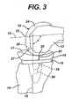
- FIGS. 1-3a knee endoprosthesis system 10 incorporating the principles of the present invention is illustrated implanted on the distal end of the femur 12 and proximal end of the tibia 14.
- the illustrated system 10includes a tibial bearing 16 that is carried by the proximal tibial component 18.
- the proximal tibial component 18is affixed to the proximal end of the tibia 14.
- the tibial bearing 16has a contoured proximal surface 17, against which the condyles 22 of the distal femoral component 24 bear.
- the distal femoral component 24is affixed to the distal end of the femur 12. Articulation of the joint is at the interface of the proximal surface 17 of the tibial bearing 16 and the condyles 22 of the distal femoral component 24.
- the joint articulationis indicated at 20 in FIGS. 1-3 ; the joint space occupied by the tibial bearing 16 is indicated at 25 in FIGS. 1-3 .
- a signal source 26is permanently affixed to the distal femoral prosthetic component 24 at a predetermined position.
- a sensor 28is permanently affixed to the proximal tibial prosthetic component 18 at a predetermined position.
- Associated electronics 30are also permanently affixed to the proximal tibial prosthetic component 18, as described in more detail below.
- the signal source 26 in the first illustrated embodimentcomprises a permanent magnet.
- a suitable neodymium magnetis available from Ogallala Electronics Division, Ogallala, Iowa of the Arnold Engineering group of SPS Technologies, Inc. of Jenkintown, Pennsylvania, for example.
- other magnetic field generatorssuch as coils as disclosed in US-A-2004/0034355 could be used.
- the sensor 28 in the first illustrated embodimentcomprises a Hall effect switch.
- a Hall effect switchproduces an electrical signal in response to the magnetic field strength or flux density generated by the permanent magnet.
- a suitable Hall effect switchis commercially available from Allegro Microsystems of Hillsborough, North Carolina and is identified as a Micropower Ultrasensitive Omnipolar Hall Effect switch, part A3212ELHLT5. It should be understood that this switch is identified as an example only; the present invention is not limited to use of any particular Hall effect switch.
- other magnetic field sensitive elementssuch as a Hall effect transducer, magnetoresistive element or a magnetic transistor, are anticipated to be useful as the sensor 28 of the present invention.
- the present inventionis not limited to use of a switch or transducer as the sensor.
- the sensorcould comprise other elements, such as an RF receiver, for example, as described in more detail below.
- the alignment of the signal source 26 and the sensor 28 and the orientation of the signal source 26 in the first illustrated embodimentvaries with the relative positions of the patient's femur and tibia. These relative positions of the patient's femur and tibia vary with the patient's activity.
- FIG. 1illustrates the knee when the patient is in a standing position.
- the mechanical axis 13 of the femur 12 and the mechanical axis 15 of the tibiadefine an angle ⁇ in the sagittal plane. This angle is about 180° when the patient is standing, and the signal source 26 and the sensor 28 are offset from each other in this plane, the sensor 28 being more anterior than the signal source 26.
- the pole 27 of the permanent magnet forming the signal source 26is oriented away from the sensor 28 when the patient is standing. Because of this offset and orientation, the magnetic field strength or flux density at the sensor 28 will be at a known level below the maximum magnetic field strength or flux density.
- the threshold of the Hall effect switchcan be selected so that the sensor 28 does not generate any electrical signal when the patient is standing as in FIG. 1 .
- FIG. 2illustrates the knee when the patient has bent the knee slightly, as in the case where the patient is walking.
- the angle ⁇ between the axes 13, 15decreases and the signal source 26 and sensor 28 are vertically aligned.
- the pole 27 of the permanent magnet forming the signal source 26is directed toward the Hall effect switch forming the sensor 28.
- the positions and orientations of the signal source 26 and sensor 28are such that the magnetic field strength or flux density is at its maximum when the patient's leg is bent slightly as in FIG. 2 .
- the threshold of the Hall effect switch forming the sensor 28is such that the Hall effect switch generates an electrical signal when the patient's knee is in the position shown in FIG. 2 , but not when the patient's knee is in the position shown in either FIG. 1 or 3 .
- the Hall effect switch(sensor 28) generates an electrical signal.
- the angle ⁇ for a system monitoring walkingmay be between 75° and 150°, for example.
- FIG. 3illustrates the knee when the knee has been fully flexed.
- the pole 27 of the permanent magnet forming the signal source 26is directed away from the Hall effect switch forming the sensor 28.
- the signal source 26 and sensor 28are offset from each other in the sagittal plane: the sensor 28 is in a more posterior position than the signal source 26. Because of this offset and orientation, the magnetic field strength or flux density at the sensor 28 will be at a known level below the maximum magnetic field strength or flux density.
- the threshold of the Hall effect switchcan be selected so that the sensor 28 does not generate any electrical signal when the patient's leg is in the position shown in FIG. 3 .
- a signalis produced when the patient is walking. This signal is produced each time the patient moves his or her knee through the position shown in FIG. 2 ; in other words, a signal is produced with each stride taken by the patient.
- the present inventionis not limited to sensing the knee joint position shown in FIG. 2 .
- the signal source and sensorcould be positioned and oriented so that a signal is produced each time the patient's knee is in the position shown in FIG. 3 .
- each electrical signal generated by the Hall effect switch (sensor 28)is transmitted to the electronic components 30 of the knee endoprosthesis system 10. As illustrated in FIGS. 1-3 , these electronic components 30 may be permanently affixed to a portion of the proximal tibial prosthetic component 18 and may be electrically connected to the sensor 28.
- the electronic components 30 of the first illustrated knee endoprosthesis systeminclude the following components: a counter component 32, a first internal power source 34, a printed circuit board 35, a modulator 36, a transmitter 38, an internal antenna 40 and a second internal power source 42.
- a suitable 24-bit counter component 32is commercially available from Texas Instruments, Inc., Dallas, Texas, part no. ADS1210P.
- the counter componentshould be able to keep a running count of the number of signals it receives from the Hall effect switch (sensor 28). In other words, each time the Hall effect switch is turned on, the change in voltage output of the switch will result in an incremental increase by the counter, which will thereby store the "equivalent" cycles of use of the joint.
- FIG. 5illustrates the operation of the sensor 28 and counter 32 schematically with reference to changes in the relationship between the axes 13, 15 of the patient's leg as the patient stands, walks and sits.
- the permanent magnet (signal source 26) and Hall effect switch (sensor 28)are positioned and oriented so that the Hall effect switch generates a voltage signal to coincide with each stride taken by the patient when walking but to not generate a signal when the patient is standing still or sitting.
- the permanent magnet and switchmay be oriented to generate a signal each time the angle ⁇ is in a range such as 70°-135°, for example.
- the first internal power source 34comprises a battery in the illustrated embodiment, such as a lithium iodine cell available from Wilson Greatbatch Technologies, Inc. of Clarence, New York.
- the batteryis connected to both the Hall effect switch (sensor 28) and the counter 32 so that each of these components has a continuous supply of power to continuously monitor use of the implant.
- the first internal power source 34could be a ferrite coil that is inductively coupled to a primary coil worn by the patient in an optimal location, such as near the joint.
- the counter 32is electrically connected or coupled to the printed circuit board 35.
- the counter 32is also electrically connected or coupled to the modulator 36 which is mounted on the printed circuit board 35 in the illustrated embodiment.
- the modulator 36serves to convert the incremental count number created and stored in the counter 32 to an encoded signal that can be transmitted from the internal transmitter 38 to a location outside of the patient's body.
- the modulator 36can encode a particular count onto an RF wave by means of varying signal amplitude, frequency or phase.
- the modulator 36is electrically connected or coupled to the transmitter 38 so that this RF wave can be transmitted outside of the patient's body through the internal antenna 40.
- the transmitter 38can also be mounted on the printed circuit board 35. It should be understood that the present invention is not limited to the use of RF waves unless expressly called for in the claims; other signals that can be encoded and transmitted from within the patient's body to outside the patient's body could be used.
- Suitable printed circuit boards 35are commercially available from Advanced Circuits of Aurora, Colorado. The particular lay out and design of the circuit board will depend on factors such as the types of parts used for the signal source and sensor. Generally, the circuit board may be designed or laid out to minimize its size and eliminate capacitive coupling. It should be understood that the invention is not limited to any particular printed circuit board unless expressly called for in the claims.
- Suitable modulators 36are commercially available from Texas Instruments, Inc., Dallas, Texas, in the form of electronic chips. Alternatively, the modulator 36 and transmitter 38 could be part of a single component.
- the transmitter 38comprises a radio-frequency transmitter. Suitable internal transmitters 38 are commercially available from Texas Instruments Inc. in the form of electronic chips. The desired characteristics of the transmitter 38 may vary depending on other components of the system; in general, the transmitter will be of an appropriate size for implantation, will transmit at a desired frequency and will not consume excessive power. Although the modulator 36 and transmitter 38 are illustrated as separate elements, a single element could perform both of these functions. Moreover, it should be understood that the present invention is not limited to any particular type of transmitter or transmission signal unless expressly called for in the claims.
- transmitters and types of signalsinclude optical data transmission.
- An IBM personal area networkmay also be usable as a transmitter.
- Acoustic energy transmission, capacitive telemetry (using electric fields) and inductive telemetry (using magnetic fields)are also possible alternatives for transmission in the present invention.
- the transmitter 38is electrically connected or coupled to the internal antenna 40 and is permanently affixed to the one of the bone-affixed prosthetic components such as prosthetic tibial component 18, as in the embodiment of FIGS. 1-4 .
- the antenna 40is hermetically sealed.
- a suitable antenna 40is available from Microstrain of Williston, Vermont. The antenna can be mounted on the printed circuit board 35 if desired.
- the illustrated embodimentalso includes a second internal power source 42.
- the second internal power source 42can comprise a battery, or an inductive power source such as ferrite coil.
- a suitable ferrite coilis a small wound coil available commercially from MicroStrain, Inc. of Williston, Vermont. The necessary characteristics of such a wound coil will depend to some extent on the design and selection of the other electronic components; power, frequency and size of the coil can be adjusted to suit the other components of the system. Alternatively, a suitable ferrite coil could be wound using standard equipment such as that available from Aumann North America, Inc. of Fort Wayne, Indiana.
- the power component 42is electrically connected to supply power to the printed circuit board 35, modulator 36, transmitter 38 and antenna 40.
- the second power sourcecan be electrically connected or coupled to the printed circuit board, and can also be mounted on the printed circuit board.
- the power for the secondary system 36, 38, 40could come from the first power source 34 using an inductively activated switch.
- an external receiver 44 and data interpretation device 46can be provided at the point of care, such as in a physician's office or at a hospital.
- the external receiver 44can comprise a radio-frequency antenna that is connected to receive the signal from the internal antenna 40 and to provide a second signal to the data interpretation device 46.
- the data interpretation device 46can be a standard computer programmed to demodulate the radio-frequency signal received from the internal transmitter 38 and internal antenna 40.
- the data interpretation device 46can also be a hand-held personal computer, a personal desk assistant, a laptop computer or any custom-designed data acquisition device.
- the data interpretation device 46can be programmed to perform calculations necessary to convert the received and demodulated signal into the number of cycles recorded by the counter 32.
- an external power source 48can also be provided at the point of care.
- the external power source 48can comprise an external coil that generates a strong localized electromagnetic or magnetostatic field that is coupled to the implanted ferrite coil (second internal power source 42) to thereby supply power to the implanted electronics 36, 38, 40.
- Suitable external coilsare commercially available from Microstrain Inc. of Williston, Vermont. Generally, since the external coils are likely to be used in close proximity to the patient, it may be desirable to select or design an external coil that will not irritate or excessively heat the patient's skin and that can be easily handled by the operator or medical technician. The external coil should be able to supply a sufficient field at the design frequency to stimulate the internal power coil.
- a suitable ferrite coilcould also be wound using standard equipment such as that available from Aumann North America, Inc. of Fort Wayne, Indiana.
- FIG. 6illustrates a possible flow diagram for information for the first illustrated embodiment of the present invention.
- the Hall effect switch 28 and counter 32are in a continuous loop inside the body so that the counter 32 is continuously storing information (the incremental count in this embodiment).
- the other implanted electronics 36, 38, 40remain inactive.
- the second implanted power sourcesupplies electrical power to the modulator 36 and transmitter 38.
- the modulator 36converts the count received from the counter 32 into a transmittable signal and the transmitter 38 transmits this transmittable signal in the form of a modulated radio-frequency wave through the internal antenna 40.
- the external antenna 44receives the transmitted wave that has been encoded by the board or chip 36 and this encoded wave is interpreted in the external computer 46 to provide the count in the form of a numerical value for use by the caregiver.
- the components 26, 28can be positioned to minimize the effects of other magnetic fields to prevent undesired activation of the sensor. In addition, steps may be taken to prevent or limit demagnetization of the permanent magnet.
- the illustrated knee endoprosthesis systems 10could be modified in several ways. For example, if there is greater concern with wear on the posterior side of the tibial bearing 16 it may be desirable to set the positions and orientations of the signal source 26 and sensor 28 so that a signal is generated when the patient's joint is in the position shown in FIG. 3 instead of when the patient's joint is in the position shown in FIG. 2 . Moreover, it may be desirable to provide a plurality of signal sources and sensors to maintain separate counts of the number of times the patient's joint is in the position shown in FIG. 2 and the number of times the patient's joint is in the position shown in FIG. 3 .
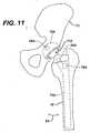
- the first prosthetic componentcan comprise an acetabular shell 70, 70A, 70B affixed to the acetabulum of the hipbone or pelvis 72.
- the second prosthetic componentcan comprise a proximal femoral component 74, 74A, 74B affixed to the proximal femur 76.
- a sensor 28, 28A, 28Bcan be affixed to one of the prosthetic components and a signal source 26, 26A, 26B can be affixed to the other prosthetic component.
- the senor 28, 28A, 28B and other electronic components 78, 78A, 78Bare affixed to the proximal femoral component 74, 74A, 74B and the signal source 26, 26A, 26B is affixed to the acetabular shell 70, 70A, 70B.
- the signal source 26 and sensor 28can be positioned and aligned so that the system counts hip flexion in the sagittal plane, as shown in FIGS. 7 to 9 , with the counter recording the number of times the prosthetic components 70, 74 are in one of the positions shown in FIGS. 7 to 9 to record movement in the directions indicated by arrow 80.
- the signal source 26A and sensor 28Acan also be positioned and oriented to record the number of times the prosthetic components 70A, 74A undergo adduction or abduction, recording movement in a coronal plane. This direction of movement is indicated by arrow 82.
- the signal source 26B and sensor 28Bcan be positioned and oriented to record the number of times the femoral component 74B is rotated about a longitudinal axis of the femur in the direction indicated by arrow 84 in FIG. 13 .
- a hip endoprosthesis systemcould include proximity sensors that record any of these movements, some of these movements, or all of these movements.
- the elements serving as the signal source 26, 26A, 26B and sensor 28, 28A, 28Bcan be any of those described above for the knee endoprosthesis system 10.
- the electronics 78, 78A, 78B associated with the signal source 26, 26A, 26B and sensor 28, 28A, 28Bcan be like those described above for the knee endoprosthesis system 10.
- Use of the illustrated hip endoprosthesis systems 11, 11A, 11Bwould be similar to that described above for the knee endoprosthesis system.
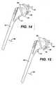
- the first prosthetic componentcan comprise a humeral component 92 and the second prosthetic component can comprise a glenoid component 94.
- a sensor 28can be affixed to one of the prosthetic components 92 or 94 and a signal source 26 can be affixed to the other prosthetic component 92 or 94.
- the sensor 28 and other electronic components 96are affixed to the proximal humeral component 92 and the signal source 26 is affixed to the glenoid component 94.
- the signal source 26 and sensor 28can be positioned and aligned so that the system counts shoulder flexion in the coronal plane, as shown in FIGS. 14 to 16 , with the counter recording the number of times the prosthetic components 92, 94 are in one of the positions shown in FIGS. 14 to 16 to record movement in the directions indicated by arrow 98.
- the signal source 26 and sensor 28can also be positioned and oriented to record the number of times the prosthetic components 92, 94 undergo movement in a sagittal or transverse plane.
- a shoulder endoprosthesis system 13could include proximity sensors that record any of these movements, some of these movements, or all of these movements.
- the elements serving as the signal source 26 and sensor 28 for the shoulder endoprosthesis system 13can be any of those described above for the knee and hip endoprosthesis systems 10, 11, 11A, 11B.
- the electronics 96 associated with the signal source 26 and sensor 28 for the shoulder endoprosthesis system 13can be like those described above for the knee and hip endoprosthesis systems 10, 11, 11A, 11B.
- shoulder endoprosthesis system 13Use of the illustrated shoulder endoprosthesis system 13 would be similar to that described above for the knee and hip endoprosthesis systems 10, 11, 11A, 11B. These principles of the present invention could be applied to other joint endoprostheses as well, such as in the elbow, wrist, ankle or other extremities.
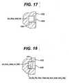
- FIGS. 17 and 18illustrate recesses 100, 101 in the body 102, 103 of endoprosthesis components.
- the body 102, 103can be any of the components described above, such as the proximal tibial component 18, the tibial bearing 16, the distal femoral component 24, the proximal femoral component 74, 74A, 74B, the acetabular cup or shell 70. 70A, 70B, the acetabular liner, the humeral component 92, the glenoid component 94, or analogous components of other prosthetics.
- the recesses 100, 101would be formed in areas of the endoprosthesis components where the presence of the recesses does not adversely affect the mechanical or physical properties of the endoprosthesis components.
- the recesses or cavities 100, 101extend inward from a non-articulating surface of the body 102, 103 of the endoprosthesis component.
- the sizes of the components 26, 28, 30, 30A, 50, 51, 78, 96can be selected to minimize the amount of space required to be taken up by these components. Components can be combined if desired.
- the signal source 26, 50 sensor 28, 51 and associated electronics 30, 30A, 78, 96can be permanently affixed in these recesses with a suitable adhesive if desired.
- the illustrated systemsare assembled prior to implantation of the endoprosthesis system.
- the recesses or cavities 100, 101can be sealed by any appropriate means after the components 26, 26A, 26B, 50, 30, 52, 78, 78A, 78B, 96, 30A, 30B, 30C are in place.
- the openings to the recesses or cavities 100, 101could be welded closed or a sealant such as a biocompatible epoxy or polyurethane, could be poured over the recess or cavity as a liquid and allowed to cure to thereby permanently secure the components in the body of the prosthetic component.
- a sealantsuch as a biocompatible epoxy or polyurethane
- Cured sealantis indicated at 104 and 105 in FIGS.17 and 18 .
- the illustrated systemsare assembled prior to implantation of the illustrated endoprosthesis systems.
- signal source 26is shown in solid rather than phantom lines in some of the accompanying drawings, this element would generally all be within the interior of the prosthetic component or on or within bone rather than on an exposed surface of a prosthetic component, although it may be possible or desirable to mount some of the electronics on a surface of one of the implants. Moreover, some of these electronic components could alternatively be formed as integral parts of the associated endoprosthesis components 18, 24, 24A, 70, 70A, 70B, 74, 74A, 74B, 92, 94.
- the endoprosthesis systemcan be provided in the form of a kit with one or more of the electronic and signal generating components provided as a discrete element.
- the electronic components 30, 30A, 51, 78, 96 and sensor 28, 28A, 28B, 51could be supplied as one or more separate discrete packages to be affixed to the patient's bones instead of to the components of the implant itself.
- the signal source 26, 26A, 26B, 50could be supplied as a separate discrete component to be affixed to the patient's bone.
- all of the electronic components 30, 30A, 30B, 52, 78, sensor 28, and the signal source 26, 26A, 26B, 50could be supplied as separate discrete components to be affixed to the patient's bones.
- the joint endoprosthesis systemcould include a load cell or strain gauge as the sensor as shown at 28C in FIGS. 19 and 20 .
- the "signal source"would comprise the load that occurs as a result of joint motion.
- the load cell or strain gauge serving as the sensor 28Ccould be affixed in the prosthetic tibial component 18C or in the tibial bearing 16C and electrically connected or coupled to internal electronics 30C including a counter so that the counter incrementally records each time the load on the prosthetic tibial component or tibial bearing exceeds a predetermined value.
- the load cell or strain gauge serving as the sensor 28Ccould be affixed in the proximal femoral component 74C or in the acetabular liner 70C and electrically coupled to internal electronics 78C so that the counter incrementally records each time the load on the proximal femoral component or acetabular liner exceeds a predetermined value. Such measurements could be taken in addition to cycle counters relying on proximity sensors. The incremental counts created by such systems can be transmitted to external receivers outside the patient's body in the manners described above for the other illustrated embodiments. These components 28C, 30C, 78C can be mounted to the prosthetic components as shown in FIGS. 17 and 18 .
- a similar systemcould be used with a shoulder endoprosthesis system or other prosthetic system where a load or strain is experienced by one or more of the prosthetic components.
- the counts of excessive loads on the prosthetic components of the joint endoprosthesis systemscan be also used to counsel patient's regarding life-style changes if the counts exceed that which is considered standard for patients.
- the joint endoprostheses of the present inventioncould be combined with other electronic features.
- an electronic component with recorded information regarding the prosthetic implantcould be included, or this information could be recorded on one of the electronic components described above.
- the joint endoprosthesis systems of the present inventioncan also be combined with joint space measurement devices.
Landscapes
- Health & Medical Sciences (AREA)
- Life Sciences & Earth Sciences (AREA)
- Veterinary Medicine (AREA)
- General Health & Medical Sciences (AREA)
- Engineering & Computer Science (AREA)
- Biomedical Technology (AREA)
- Heart & Thoracic Surgery (AREA)
- Public Health (AREA)
- Animal Behavior & Ethology (AREA)
- Orthopedic Medicine & Surgery (AREA)
- Oral & Maxillofacial Surgery (AREA)
- Transplantation (AREA)
- Vascular Medicine (AREA)
- Cardiology (AREA)
- Pathology (AREA)
- Physics & Mathematics (AREA)
- Biophysics (AREA)
- Medical Informatics (AREA)
- Molecular Biology (AREA)
- Surgery (AREA)
- Dentistry (AREA)
- Physical Education & Sports Medicine (AREA)
- Prostheses (AREA)
- Pharmaceuticals Containing Other Organic And Inorganic Compounds (AREA)
Abstract
Description
- The present invention relates to joint endoprosthesis systems.
- Human joints can become damaged as a result of accident or illness. Such damage can be, for example, to the articular cartilage covering the ends of the bones at the joint as well as the intra-articular cartilage between the ends of the adjacent bones of the joint. When the damage to the joint is severe, a joint endoprosthesis can be implanted to improve the comfort and mobility of the patient.
- Joint endoprostheses have been developed to replace native tissue of several human joints. There are a variety of knee prostheses, hip prostheses, shoulder prostheses, ankle prostheses and wrist prostheses available to relieve patient suffering. Such devices are available, for example, from the assignee of the present invention, DePuy Orthopaedics, Inc. of Warsaw, Indiana.
- Standard joint endoprostheses include metal components that are affixed to the articulating ends of the bones of the joint and commonly include a bearing component positioned between the metal components. Standard bearing components of joint endoprostheses have a surface against which one of the metal components articulates. For example, hip endoprostheses include a metal femoral component to be affixed to the proximal femur and a metal cup to be affixed to the acetabulum. Many of these standard hip endoprostheses include a liner in the acetabular cup against which the femoral component articulates. Knee prostheses commonly include a femoral component to be affixed to the distal femur and a tibial component to be affixed to the proximal tibia. Bearings are typically between the femoral and tibial components. Similar systems with bearings are available to replace other joints in the body.
- Standard bearings for joint endoprostheses are made of ultrahigh molecular weight polyethylene (UHMWPE), ceramic and metal. Bearing wear is problematic in the orthopaedic field. Several patents have addressed the problem particles produced by UHMWPE wear, and the association of these particles with osteolysis. See, for example:
US-6281264 "Chemically crosslinked ultrahigh molecular weight polyethylene for artificial human joints", andUS-6228900 "Crosslinking of polyethylene for low wear using radiation and thermal treatments". US-5197488 discloses the features of the preamble ofclaim 1. This document shows an instrument for measuring load in a knee joint prosthesis during a procedure to implant the prosthesis. A transducer is positioned between bone engaging members to produce an output signal which is representative of forces applied to the bone engaging members.- Undue bearing wear can result in conditions requiring that the joint endoprosthesis be removed and replaced in a revision procedure. Accordingly, early detection of bearing wear could find use as a signal to the orthopaedic surgeon that some type of intervention is needed before the condition degenerates to the point of requiring revision surgery. For example, the surgeon may determine that the patient needs to make some lifestyle changes if revision is to be postponed. Moreover, if therapeutic agents to treat early stage osteolysis are available, these agents could be administered before the condition degenerates to the point where revision surgery is necessary.
- The present invention addresses the need to provide readily accessible data for monitoring joint endoprostheses after implantation. Data on the extent of use of the joint endoprosthesis is made available to allow the caregiver to intervene if necessary if the joint endoprosthesis is being used excessively.
- In one aspect, the present invention provides a joint endoprosthesis system as defined in
claim 1. - The system can be used in a method of monitoring use of an implanted joint endoprosthesis system. The joint endoprosthesis system includes a first prosthetic component affixed to one bone of the joint and a second prosthetic component affixed to another bone of the joint. The first and second prosthetic components are movable through a plurality of positions. The method comprises the steps of generating a signal each time the first and second prosthetic components are in a predetermined position, storing an incremental count of the number of signals generated within the patient's body, and converting the incremental count stored into a transmittable signal. The transmittable signal is transmitted to a position outside of the patient's body and the incremental count is determined outside of the patient's body.
- The invention will be better understood by reference to the figures of the drawings wherein like numbers denote like parts throughout and wherein:
FIG. 1 is a side elevation of a first embodiment of a knee joint endoprosthesis system implanted on a distal femur and proximal tibia, showing the bones and prosthetic components in extension as when the patient is in a standing position;FIG. 2 is a side elevation of the knee joint endoprosthesis system ofFIG. 1 , showing the bones and prosthetic components when the leg is slightly flexed, as when the patient is walking;FIG. 3 is a side elevation of the knee joint endoprosthesis system ofFIGS. 1 and2 , showing the bones and prosthetic components when the leg is fully flexed as when the patient is squatting;FIG. 4 is a schematic illustration of the components of the knee joint endoprosthesis system ofFIGS. 1 to 3 , showing external components as well as those implanted in the patient;FIG. 5 is a schematic illustration of operation of the knee joint endoprosthesis system ofFIGS. 1 to 4 , illustrating the relationship between various positions of the patient's leg, the output of a sensor and an incremental count that is maintained by the endoprosthesis system;FIG. 6 is a flow chart illustrating use of the knee endoprosthesis system ofFIGS. 1 to 5 ;FIG. 7 is a side elevation of a hip joint endoprosthesis system implanted on a portion of the hipbone and proximal femur, showing the bones and prosthetic components in extension as when the patient is in a standing position;FIG. 8 is a side elevation of the hip joint endoprosthesis system ofFIG. 7 , showing the bones and prosthetic components when the hip is slightly flexed by rotation in a sagittal plane, as when the patient is walking;FIG. 9 is a side elevation of the hip joint endoprosthesis system ofFIGS. 7 and 8 showing the bones and prosthetic components when the hip is fully flexed by rotation in a sagittal plane as when the patient is squatting;FIG. 10 is a front elevation of a hip joint endoprosthesis system implanted on a portion of the hipbone and proximal femur, showing the bones and prosthetic components in extension as when the patient is in a normal standing position;FIG. 11 is a front elevation of the hip joint endoprosthesis system ofFIG. 10 , showing the bones and prosthetic components when the hip is slightly abducted by rotation in a coronal plane;FIG. 12 is a side elevation of a hip joint endoprosthesis system implanted on a portion of the hipbone and the proximal femur, showing the bones and prosthetic components in extension as when the patient is in a normal standing position;FIG. 13 is a side elevation of the hip joint endoprosthesis system ofFIG. 12 , showing the bones and prosthetic components when the femur and femoral prosthetic component are rotated slightly in a transverse plane;FIG. 14 is a side elevation of a shoulder joint endoprosthesis system, showing the humeral and glenoid components in one position;FIG. 15 is a side elevation of the shoulder joint endoprosthesis system ofFIG. 14 , showing the humeral and glenoid components in a second position;FIG. 16 is a side elevation of the shoulder joint endoprosthesis system ofFIGS. 14 and 15 , showing the humeral and glenoid components in a third position;FIG. 17 is a is a partial cross-section of a body of an endoprosthesis component with a signal source secured within a recess or cavity in the body portion of the endoprosthesis component;FIG. 18 is another partial cross-section of a portion of a body of an endoprosthesis component with a sensor and associated electronics secured within a recess or cavity in the body portion of the endoprosthesis component;FIG. 19 is a side elevation of a knee joint endoprosthesis system implanted on a distal femur and proximal tibia, showing the bones and prosthetic components in extension as when the patient is in a standing position; andFIG. 20 is a side elevation of a hip joint endoprosthesis system implanted on a portion of the hip bone and the proximal femur, showing the bones and prosthetic components in extension as when the patient is in a normal standing position.- Joint endoprosthesis systems incorporating the principles of the present invention are illustrated in the accompanying drawings. In
FIGS. 1 to 6 and19 , the system is a knee endoprosthesis system. InFIGS. 7 to 13 and20 , the system is a hip endoprosthesis system. InFIGS. 14 to 16 , the system is a shoulder endoprosthesis system.FIGS. 17 and 18 are applicable to all of the illustrated endoprosthesis systems. It should be understood thatFIGS. 1-20 are diagrammatic illustrations of these systems, and do not depict all of the features of the prosthetic components. It should also be understood that the teachings of the present invention can also be applied to other joint endoprostheses, including wrist, elbow and ankle endoprostheses and endoprostheses for use with the digits of the extremities. - Each of the illustrated knee endoprosthesis and hip endoprosthesis systems includes three basic components: a first prosthetic component to be affixed to one bone of the joint, a second prosthetic component to be affixed to the other bone of the joint, and a bearing component to be positioned at the joint articulation, in the joint space between the first and second prosthetic components. In the knee endoprosthesis system, the first component comprises a distal femoral component with condyles defining an articulating surface. The second component comprises a proximal tibial component. The bearing is a tibial bearing carried by the tibial component. The tibial bearing has an upper surface bearing against the condyles of the distal femoral component. The interface of the condyles of the distal femoral component and the upper surface of the tibial bearing defines the articulation of the knee prosthesis system. The tibial bearing occupies the joint space between the distal femoral and proximal tibial components, and the thickness of the tibial bearing corresponds with the thickness of the joint space in the knee endoprosthesis system. In the hip prosthesis system, the first component comprises an acetabular cup or shell to be affixed to a prepared space in the patient's hip bone. The second component comprises a proximal femoral component. The proximal femoral component has a femoral head defining an articulating surface. The bearing is an acetabular liner carried by the acetabular cup. The acetabular liner has a curved surface bearing against the femoral head of the proximal femoral component. The interface of the femoral head and the curved surface of the acetabular liner defines the articulation of the hip prosthesis system. The acetabular liner occupies the joint space between the acetabular cup and the femoral head, and the thickness of the acetabular liner corresponds with the thickness of the joint space of the hip endoprosthesis system. Analogous components are present in other joint endoprosthesis systems.
- The illustrated shoulder endoprosthesis system includes two basic components. The first component comprises a humeral component, including a stem and a humeral head. The second component comprises a glenoid component. The surface of the humeral head defines an articulating surface. The glenoid component has a surface that bears against the humeral head. The interface of the humeral head and the glenoid component defines the articulation of the shoulder joint prosthesis system. A portion of the glenoid component occupies the joint space, and the thickness of this portion of the glenoid component corresponds with the thickness of the joint space of the shoulder endoprosthesis system.
- In each of the illustrated endoprosthesis systems, the implants are designed to articulate as the patient goes through normal life routines, such as walking, sitting and lifting. During such normal routines, the distal surface of the femoral condyles of the knee endoprosthesis articulate against the tibial bearing surface, the surface of the femoral head of the hip endoprosthesis articulates against the acetabular liner and the surface of the humeral head of the shoulder endoprosthesis articulates against the glenoid component.
- The femoral, tibial and bearing components for the knee endoprosthesis system of the present invention can have features of known commercially available knee endoprosthesis systems, such as those available from DePuy Orthopaedics, Inc. of Warsaw, Indiana. Similarly, the femoral, acetabular and bearing components for the hip endoprosthesis system of the present invention can have features of known commercially available hip systems, such as those available from DePuy Orthopaedics, Inc. of Warsaw, Indiana. The humeral and glenoid components of the shoulder endoprosthesis system of the present invention can also have features of known commercially available shoulder systems, such as those available from DePuy Orthopaedics, Inc. of Warsaw, Indiana. The components of these systems can also have features of the commercially available products of other suppliers of knee, hip and shoulder endoprostheses, such as those available from Zimmer, Inc. of Warsaw, Indiana, Biomet, Inc. of Warsaw, Indiana, Stryker Howmedica Osteonics, Inc. of Mahwah, New Jersey, and Smith & Nephew, Inc. of Memphis, Tennessee. It should be understood that it is anticipated that the endoprosthesis systems of the present invention may include subsequent improvements to these commercial products. It should also be understood that although standard materials such as cobalt chrome, titanium, polyethylene and ceramic, can be used for these components of the joint endoprostheses, the present invention is not limited to any particular material for any of the components unless expressly set forth in the claims.
- In addition to the standard components, the endoprosthesis systems of the present invention include additional components for monitoring use of the joint endoprosthesis systems after implantation. As explained in more detail below, these additional components include a signal source, a recording device and associated electronics that provide data for determining the number of times the joint endoprosthesis is cycled through a particular motion or motions. These additional components may be permanently affixed to the standard joint endoprosthesis components, and the standard joint endoprosthesis components may be modified slightly to allow for this permanent affixation.
- In the illustrated embodiments, the signal source serves to generate a first signal. If the signal source is a permanent magnet, the signal generated is a magnetic field or a magnetic flux density.
- "Proximity sensor" is intended to encompass devices such as switches, transducers, transponders, and electromagnetic sensors. The sensor functions to sense a characteristic of the first signal generated by the signal source. For example, the sensor may function to sense the magnitude or orientation of the magnetic field or flux density generated by a permanent magnet at a particular location. The sensor may also serve to generate a second signal that has a characteristic that varies depending on some characteristic of the signal it has sensed.
- Generally, in the illustrated embodiments, where a signal source is used, the signal source is positioned on one side of the articulation or joint space of the joint endoprosthesis and the sensor or target is positioned on the opposite side of the endoprosthesis articulation. The signal source is at a fixed position with respect to one of the endoprosthesis components and the sensor or target is at a fixed position with respect to the other endoprosthesis component on the opposite side of the articulation. Since the positions of the signal source and sensor or target are fixed with respect to the bone-affixed components of the joint endoprosthesis, changes in the relative positions of the signal source and sensor or target that correspond with particular movements of the patient can be counted. Thus, if the distance between the signal source and sensor or target decreases to a predetermined level, this decrease in distance corresponds with a particular relative position of the bone-affixed components of the endoprosthesis system. In other words, the proximity of the signal source and sensor or target corresponds with a particular relative position of the bone-affixed components. By counting the number of times the bone-affixed components are in a particular relative position, use of the endoprosthesis system can be monitored. Thus, with the endoprosthesis system of the present invention, the amount of walking, running, lifting or changes in positions can be monitored. If the caregiver (such as the orthopaedic surgeon) determines that the patient's use of the implant exceeds the normal range of use for such an implant, the caregiver can intervene before the patient exhibits a condition requiring revision surgery. For example, the caregiver could suggest lifestyle changes that would lessen overuse of the endoprosthesis.
- The system may also compensate for movement of the implant components through migration or subsidence for example. Such compensation can be accomplished by selecting a sensor with a threshold activation range that is unaffected by a range of movement associated with migration or subsidence. It should also be understood that non-weight-bearing movement of the implant components (such as when the patient stretches the affected limb) will be counted as part of the cycle count process, and that consideration may be given to such movements in analyzing the results of the cycle counting. Referring now to
FIGS. 1-3 , aknee endoprosthesis system 10 incorporating the principles of the present invention is illustrated implanted on the distal end of thefemur 12 and proximal end of thetibia 14. The illustratedsystem 10 includes atibial bearing 16 that is carried by theproximal tibial component 18. Theproximal tibial component 18 is affixed to the proximal end of thetibia 14. Thetibial bearing 16 has a contouredproximal surface 17, against which thecondyles 22 of the distalfemoral component 24 bear. The distalfemoral component 24 is affixed to the distal end of thefemur 12. Articulation of the joint is at the interface of theproximal surface 17 of thetibial bearing 16 and thecondyles 22 of the distalfemoral component 24. The joint articulation is indicated at 20 inFIGS. 1-3 ; the joint space occupied by thetibial bearing 16 is indicated at 25 inFIGS. 1-3 . - In the embodiment of
FIGS. 1-3 , asignal source 26 is permanently affixed to the distal femoralprosthetic component 24 at a predetermined position. Asensor 28 is permanently affixed to the proximal tibialprosthetic component 18 at a predetermined position.Associated electronics 30 are also permanently affixed to the proximal tibialprosthetic component 18, as described in more detail below. - The
signal source 26 in the first illustrated embodiment comprises a permanent magnet. A suitable neodymium magnet is available from Ogallala Electronics Division, Ogallala, Nebraska of the Arnold Engineering group of SPS Technologies, Inc. of Jenkintown, Pennsylvania, for example. However, it should be understood that the present invention is not limited to use of any particular type of magnet unless expressly called for in the claims; other magnetic field generators, such as coils as disclosed in US-A-2004/0034355 could be used. - The
sensor 28 in the first illustrated embodiment comprises a Hall effect switch. A Hall effect switch produces an electrical signal in response to the magnetic field strength or flux density generated by the permanent magnet. A suitable Hall effect switch is commercially available from Allegro Microsystems of Hillsborough, North Carolina and is identified as a Micropower Ultrasensitive Omnipolar Hall Effect switch, part A3212ELHLT5. It should be understood that this switch is identified as an example only; the present invention is not limited to use of any particular Hall effect switch. In addition, other magnetic field sensitive elements, such as a Hall effect transducer, magnetoresistive element or a magnetic transistor, are anticipated to be useful as thesensor 28 of the present invention. Moreover, the present invention is not limited to use of a switch or transducer as the sensor. The sensor could comprise other elements, such as an RF receiver, for example, as described in more detail below. - As can be seen from a comparison of
FIGS. 1-3 , the alignment of thesignal source 26 and thesensor 28 and the orientation of thesignal source 26 in the first illustrated embodiment varies with the relative positions of the patient's femur and tibia. These relative positions of the patient's femur and tibia vary with the patient's activity. FIG. 1 illustrates the knee when the patient is in a standing position. In this position, themechanical axis 13 of thefemur 12 and themechanical axis 15 of the tibia define an angle α in the sagittal plane. This angle is about 180° when the patient is standing, and thesignal source 26 and thesensor 28 are offset from each other in this plane, thesensor 28 being more anterior than thesignal source 26. Moreover, thepole 27 of the permanent magnet forming thesignal source 26 is oriented away from thesensor 28 when the patient is standing. Because of this offset and orientation, the magnetic field strength or flux density at thesensor 28 will be at a known level below the maximum magnetic field strength or flux density. The threshold of the Hall effect switch can be selected so that thesensor 28 does not generate any electrical signal when the patient is standing as inFIG. 1 .FIG. 2 illustrates the knee when the patient has bent the knee slightly, as in the case where the patient is walking. In this position, the angle α between theaxes signal source 26 andsensor 28 are vertically aligned. Moreover, thepole 27 of the permanent magnet forming thesignal source 26 is directed toward the Hall effect switch forming thesensor 28. Thus, the positions and orientations of thesignal source 26 andsensor 28 are such that the magnetic field strength or flux density is at its maximum when the patient's leg is bent slightly as inFIG. 2 . The threshold of the Hall effect switch forming thesensor 28 is such that the Hall effect switch generates an electrical signal when the patient's knee is in the position shown inFIG. 2 , but not when the patient's knee is in the position shown in eitherFIG. 1 or3 . Thus, when the angle α is at a predetermined level, the Hall effect switch (sensor 28) generates an electrical signal. The angle α for a system monitoring walking may be between 75° and 150°, for example.FIG. 3 illustrates the knee when the knee has been fully flexed. At this angle between the femur and tibia, thepole 27 of the permanent magnet forming thesignal source 26 is directed away from the Hall effect switch forming thesensor 28. In addition, thesignal source 26 andsensor 28 are offset from each other in the sagittal plane: thesensor 28 is in a more posterior position than thesignal source 26. Because of this offset and orientation, the magnetic field strength or flux density at thesensor 28 will be at a known level below the maximum magnetic field strength or flux density. The threshold of the Hall effect switch can be selected so that thesensor 28 does not generate any electrical signal when the patient's leg is in the position shown inFIG. 3 .- Thus, in the first illustrated embodiment, a signal is produced when the patient is walking. This signal is produced each time the patient moves his or her knee through the position shown in
FIG. 2 ; in other words, a signal is produced with each stride taken by the patient. It should be understood that the present invention is not limited to sensing the knee joint position shown inFIG. 2 . Alternatively or additionally, for example, the signal source and sensor could be positioned and oriented so that a signal is produced each time the patient's knee is in the position shown inFIG. 3 . - To produce usable data from these signals, each electrical signal generated by the Hall effect switch (sensor 28) is transmitted to the
electronic components 30 of theknee endoprosthesis system 10. As illustrated inFIGS. 1-3 , theseelectronic components 30 may be permanently affixed to a portion of the proximal tibialprosthetic component 18 and may be electrically connected to thesensor 28. - As shown schematically in
FIG. 4 , theelectronic components 30 of the first illustrated knee endoprosthesis system include the following components: acounter component 32, a firstinternal power source 34, a printedcircuit board 35, amodulator 36, atransmitter 38, aninternal antenna 40 and a secondinternal power source 42. - A suitable 24-
bit counter component 32 is commercially available from Texas Instruments, Inc., Dallas, Texas, part no. ADS1210P. The counter component should be able to keep a running count of the number of signals it receives from the Hall effect switch (sensor 28). In other words, each time the Hall effect switch is turned on, the change in voltage output of the switch will result in an incremental increase by the counter, which will thereby store the "equivalent" cycles of use of the joint. FIG. 5 illustrates the operation of thesensor 28 and counter 32 schematically with reference to changes in the relationship between theaxes FIG. 5 , there is no voltage signal from the Hall effect switch (sensor 28) and thecounter 32 does not register any incremental change. Similarly, when the patient is sitting as in position H ofFIG. 5 , the Hall effect switch (sensor 28) does not generate a signal and thecounter 32 does not register any incremental change. However, when the patient moves his or her leg through positions B, E, G and I ofFIG. 5 , the angle α falls within the predetermined range, a voltage output is created by theHall effect switch 28, shown at 43, 45, 47 and 49 inFIG. 5 , each time the leg is in this position, and thecounter 32 registers the rise in voltage as a single increment as shown by the numbers "1", "2", "3" and "4"inFIG. 5 .- The first
internal power source 34 comprises a battery in the illustrated embodiment, such as a lithium iodine cell available from Wilson Greatbatch Technologies, Inc. of Clarence, New York. The battery is connected to both the Hall effect switch (sensor 28) and thecounter 32 so that each of these components has a continuous supply of power to continuously monitor use of the implant. Alternatively, the firstinternal power source 34 could be a ferrite coil that is inductively coupled to a primary coil worn by the patient in an optimal location, such as near the joint. - The
counter 32 is electrically connected or coupled to the printedcircuit board 35. Thecounter 32 is also electrically connected or coupled to themodulator 36 which is mounted on the printedcircuit board 35 in the illustrated embodiment. Themodulator 36 serves to convert the incremental count number created and stored in thecounter 32 to an encoded signal that can be transmitted from theinternal transmitter 38 to a location outside of the patient's body. For example, themodulator 36 can encode a particular count onto an RF wave by means of varying signal amplitude, frequency or phase. Themodulator 36 is electrically connected or coupled to thetransmitter 38 so that this RF wave can be transmitted outside of the patient's body through theinternal antenna 40. Thetransmitter 38 can also be mounted on the printedcircuit board 35. It should be understood that the present invention is not limited to the use of RF waves unless expressly called for in the claims; other signals that can be encoded and transmitted from within the patient's body to outside the patient's body could be used. - Suitable printed
circuit boards 35 are commercially available from Advanced Circuits of Aurora, Colorado. The particular lay out and design of the circuit board will depend on factors such as the types of parts used for the signal source and sensor. Generally, the circuit board may be designed or laid out to minimize its size and eliminate capacitive coupling. It should be understood that the invention is not limited to any particular printed circuit board unless expressly called for in the claims. Suitable modulators 36 are commercially available from Texas Instruments, Inc., Dallas, Texas, in the form of electronic chips. Alternatively, themodulator 36 andtransmitter 38 could be part of a single component.- In the illustrated embodiment, the
transmitter 38 comprises a radio-frequency transmitter. Suitableinternal transmitters 38 are commercially available from Texas Instruments Inc. in the form of electronic chips. The desired characteristics of thetransmitter 38 may vary depending on other components of the system; in general, the transmitter will be of an appropriate size for implantation, will transmit at a desired frequency and will not consume excessive power. Although themodulator 36 andtransmitter 38 are illustrated as separate elements, a single element could perform both of these functions. Moreover, it should be understood that the present invention is not limited to any particular type of transmitter or transmission signal unless expressly called for in the claims. - Other possible types of transmitters and types of signals include optical data transmission. An IBM personal area network may also be usable as a transmitter. Acoustic energy transmission, capacitive telemetry (using electric fields) and inductive telemetry (using magnetic fields) are also possible alternatives for transmission in the present invention.
- The
transmitter 38 is electrically connected or coupled to theinternal antenna 40 and is permanently affixed to the one of the bone-affixed prosthetic components such asprosthetic tibial component 18, as in the embodiment ofFIGS. 1-4 . In the illustrated embodiment, theantenna 40 is hermetically sealed. Asuitable antenna 40 is available from Microstrain of Williston, Vermont. The antenna can be mounted on the printedcircuit board 35 if desired. - The illustrated embodiment also includes a second
internal power source 42. The secondinternal power source 42 can comprise a battery, or an inductive power source such as ferrite coil. A suitable ferrite coil is a small wound coil available commercially from MicroStrain, Inc. of Williston, Vermont. The necessary characteristics of such a wound coil will depend to some extent on the design and selection of the other electronic components; power, frequency and size of the coil can be adjusted to suit the other components of the system. Alternatively, a suitable ferrite coil could be wound using standard equipment such as that available from Aumann North America, Inc. of Fort Wayne, Indiana. Thepower component 42 is electrically connected to supply power to the printedcircuit board 35,modulator 36,transmitter 38 andantenna 40. It should be understood that it may not be necessary to include a second power source; all of the implanted electrical components associated with one side of the joint articulation could be connected to be powered by a single power source, such as an internal battery. However, since the Hall effect switch (sensor 28) and counter 32 of the first illustrated embodiment receive a continuous power supply, it may be desirable to maximize the useful life of the power source used for these elements by utilizing a second power source for the components that are only used periodically. The second power source can be electrically connected or coupled to the printed circuit board, and can also be mounted on the printed circuit board. Alternatively, instead of providing a second power source, the power for thesecondary system first power source 34 using an inductively activated switch. - As shown schematically in
FIG. 4 , anexternal receiver 44 anddata interpretation device 46 can be provided at the point of care, such as in a physician's office or at a hospital. Theexternal receiver 44 can comprise a radio-frequency antenna that is connected to receive the signal from theinternal antenna 40 and to provide a second signal to thedata interpretation device 46. Thedata interpretation device 46 can be a standard computer programmed to demodulate the radio-frequency signal received from theinternal transmitter 38 andinternal antenna 40. Thedata interpretation device 46 can also be a hand-held personal computer, a personal desk assistant, a laptop computer or any custom-designed data acquisition device. Thedata interpretation device 46 can be programmed to perform calculations necessary to convert the received and demodulated signal into the number of cycles recorded by thecounter 32. It is anticipated that a software engineer or programmer could readily program the externaldata interpretation device 46 to perform this calculation. This number of cycles can be compared to a base reference to determine if the patient's life-style is likely to adversely affect the useful life of any one of the joint endoprosthesis components. - If the second
internal power source 42 comprises an inductor, anexternal power source 48 can also be provided at the point of care. Theexternal power source 48 can comprise an external coil that generates a strong localized electromagnetic or magnetostatic field that is coupled to the implanted ferrite coil (second internal power source 42) to thereby supply power to the implantedelectronics FIG. 6 illustrates a possible flow diagram for information for the first illustrated embodiment of the present invention. As there shown, theHall effect switch 28 and counter 32 are in a continuous loop inside the body so that thecounter 32 is continuously storing information (the incremental count in this embodiment). If there is no external power source, the other implantedelectronics modulator 36 andtransmitter 38. Themodulator 36 converts the count received from thecounter 32 into a transmittable signal and thetransmitter 38 transmits this transmittable signal in the form of a modulated radio-frequency wave through theinternal antenna 40. Theexternal antenna 44 receives the transmitted wave that has been encoded by the board orchip 36 and this encoded wave is interpreted in theexternal computer 46 to provide the count in the form of a numerical value for use by the caregiver.- The
components - The illustrated
knee endoprosthesis systems 10 could be modified in several ways. For example, if there is greater concern with wear on the posterior side of thetibial bearing 16 it may be desirable to set the positions and orientations of thesignal source 26 andsensor 28 so that a signal is generated when the patient's joint is in the position shown inFIG. 3 instead of when the patient's joint is in the position shown inFIG. 2 . Moreover, it may be desirable to provide a plurality of signal sources and sensors to maintain separate counts of the number of times the patient's joint is in the position shown inFIG. 2 and the number of times the patient's joint is in the position shown inFIG. 3 . - Application of the principles of the present invention to
hip endoprosthesis systems FIGS. 7 to 13 . As shown inFIGS. 7 to 13 , the first prosthetic component can comprise anacetabular shell pelvis 72. The second prosthetic component can comprise a proximalfemoral component proximal femur 76. Asensor signal source sensor electronic components femoral component signal source acetabular shell signal source 26 andsensor 28 can be positioned and aligned so that the system counts hip flexion in the sagittal plane, as shown inFIGS. 7 to 9 , with the counter recording the number of times theprosthetic components FIGS. 7 to 9 to record movement in the directions indicated byarrow 80. - As shown in
FIGS. 10 and11 , thesignal source 26A andsensor 28A can also be positioned and oriented to record the number of times theprosthetic components arrow 82. In addition, thesignal source 26B andsensor 28B can be positioned and oriented to record the number of times thefemoral component 74B is rotated about a longitudinal axis of the femur in the direction indicated byarrow 84 inFIG. 13 . A hip endoprosthesis system could include proximity sensors that record any of these movements, some of these movements, or all of these movements. - The elements serving as the
signal source sensor knee endoprosthesis system 10. In addition, theelectronics signal source sensor knee endoprosthesis system 10. Use of the illustratedhip endoprosthesis systems - Application of the principles of the present invention to a
shoulder endoprosthesis system 13 is illustrated inFIGS. 14 to 16 . As shown inFIGS. 14 to 16 , the first prosthetic component can comprise ahumeral component 92 and the second prosthetic component can comprise aglenoid component 94. Asensor 28 can be affixed to one of theprosthetic components signal source 26 can be affixed to the otherprosthetic component sensor 28 and otherelectronic components 96 are affixed to the proximalhumeral component 92 and thesignal source 26 is affixed to theglenoid component 94. Thesignal source 26 andsensor 28 can be positioned and aligned so that the system counts shoulder flexion in the coronal plane, as shown inFIGS. 14 to 16 , with the counter recording the number of times theprosthetic components FIGS. 14 to 16 to record movement in the directions indicated byarrow 98. Thesignal source 26 andsensor 28 can also be positioned and oriented to record the number of times theprosthetic components shoulder endoprosthesis system 13 could include proximity sensors that record any of these movements, some of these movements, or all of these movements. - The elements serving as the
signal source 26 andsensor 28 for theshoulder endoprosthesis system 13 can be any of those described above for the knee andhip endoprosthesis systems electronics 96 associated with thesignal source 26 andsensor 28 for theshoulder endoprosthesis system 13 can be like those described above for the knee andhip endoprosthesis systems - Use of the illustrated
shoulder endoprosthesis system 13 would be similar to that described above for the knee andhip endoprosthesis systems - In all of the illustrated embodiments, the signal source, sensor and associated electronics could be held in recesses in the associated endoprosthesis components.
FIGS. 17 and 18 illustraterecesses body body proximal tibial component 18, thetibial bearing 16, the distalfemoral component 24, the proximalfemoral component shell 70. 70A, 70B, the acetabular liner, thehumeral component 92, theglenoid component 94, or analogous components of other prosthetics. Therecesses cavities body - The sizes of the
components signal source 26, 50sensor 28, 51 and associatedelectronics cavities components cavities FIGS.17 and 18 . The illustrated systems are assembled prior to implantation of the illustrated endoprosthesis systems. - It should be understood that while the
signal source 26 is shown in solid rather than phantom lines in some of the accompanying drawings, this element would generally all be within the interior of the prosthetic component or on or within bone rather than on an exposed surface of a prosthetic component, although it may be possible or desirable to mount some of the electronics on a surface of one of the implants. Moreover, some of these electronic components could alternatively be formed as integral parts of the associatedendoprosthesis components - In all of the illustrated embodiments, it is anticipated that suppliers of the signal source, sensor and associated electronics can provide design assistance to minimize the size of these components.
- Other variations in the illustrated embodiments are possible. For example, the endoprosthesis system can be provided in the form of a kit with one or more of the electronic and signal generating components provided as a discrete element. For example, the
electronic components sensor signal source electronic components sensor 28, and thesignal source - Other types of measurements can be made and incrementally counted as well. For example, based on the fact that each knee or hip joint periodically bears the load of the patient's weight during walking or running, the joint endoprosthesis system could include a load cell or strain gauge as the sensor as shown at 28C in
FIGS. 19 and 20 . In such a case, the "signal source" would comprise the load that occurs as a result of joint motion. For a knee endoprosthesis system as inFIG. 19 , the load cell or strain gauge serving as thesensor 28C could be affixed in theprosthetic tibial component 18C or in thetibial bearing 16C and electrically connected or coupled tointernal electronics 30C including a counter so that the counter incrementally records each time the load on the prosthetic tibial component or tibial bearing exceeds a predetermined value. For a hip endoprosthesis system as inFIG. 20 , the load cell or strain gauge serving as thesensor 28C could be affixed in the proximalfemoral component 74C or in theacetabular liner 70C and electrically coupled tointernal electronics 78C so that the counter incrementally records each time the load on the proximal femoral component or acetabular liner exceeds a predetermined value. Such measurements could be taken in addition to cycle counters relying on proximity sensors. The incremental counts created by such systems can be transmitted to external receivers outside the patient's body in the manners described above for the other illustrated embodiments. Thesecomponents FIGS. 17 and 18 . A similar system could be used with a shoulder endoprosthesis system or other prosthetic system where a load or strain is experienced by one or more of the prosthetic components. The counts of excessive loads on the prosthetic components of the joint endoprosthesis systems can be also used to counsel patient's regarding life-style changes if the counts exceed that which is considered standard for patients. - The joint endoprostheses of the present invention could be combined with other electronic features. For example, an electronic component with recorded information regarding the prosthetic implant could be included, or this information could be recorded on one of the electronic components described above. The joint endoprosthesis systems of the present invention can also be combined with joint space measurement devices.
- While the present invention has been described with respect to post-implantation patient care, the principles of the present invention could be applied to other uses as well, such as in intraoperative assessment of the prosthetic implant.
Claims (15)
- A joint endoprosthesis system (10) to be implanted in a patient, the system comprising:a first prosthetic component (24) to be affixed to one bone (12) of the joint, anda second prosthetic component (18) to be affixed to the other bone (14) of the joint,a sensor (28) which is fixed to one of the first and second prosthetic components which generates a signal,a counter (32) for storing the number of signals generated by the sensor,characterisedinthatthe system includes:a magnetic field source (26) which is fixed to the other of the first and second prosthetic components,and furthercharacterised in that the sensor generates the signaleach time the bones of the joint are in a predetermined position, in response to a change in the strength of the magnetic field generated by the magnetic field source that is detected by the sensor.
- The system of claim 1, in which a signal is generated when the angle between at least one of the bones (12, 14) of the joint and a reference has a predetermined value.
- The system of claim 2, in which the sensor (28) comprises a proximity sensor.
- The system of claim 2, in which the sensor (28) comprises a transducer.
- The system of claim 4, in which the transducer (28) comprises a Hall effect switch.
- The system of claim 2, in which the sensor (28) comprises a transponder.
- The system of claim 2, in which the sensor (28) comprises a switch.
- The system of claim 1, in which the magnetic field source (22) is a permanent magnet.
- The system of claim 1, in which the predetermined condition for generating a signal is associated with one of the following patient actions: walking; sitting; running; squatting and lifting.
- The system of claim 1, which includes a first power source (34) for supplying continuous power to the counter (32).
- The system of claim 1, which includes a transmitter (38) for transmitting data related to the number of signals stored.
- The system of claim 11, which includes a first power source (34) for supplying continuous power to the counter (32), and a second power source (42) for selectively supplying power to the transmitter (38).
- The system of claim 1, which is a knee joint system in which the first prosthetic component comprises a distal femoral component and the second prosthetic component comprises a proximal tibial component.
- The system of claim 1, which is a hip joint system in which the first prosthetic component comprises a proximal femoral component and the second prosthetic component comprises an acetabular cup.
- The system of claim 1, which is a shoulder joint system in which the first prosthetic component comprises a humeral component and the second prosthetic component comprises a glenoid component.
Applications Claiming Priority (2)
| Application Number | Priority Date | Filing Date | Title |
|---|---|---|---|
| US48676203P | 2003-07-11 | 2003-07-11 | |
| PCT/US2004/022254WO2005007025A2 (en) | 2003-07-11 | 2004-07-09 | In vivo joint implant cycle counter |
Publications (3)
| Publication Number | Publication Date |
|---|---|
| EP1648349A2 EP1648349A2 (en) | 2006-04-26 |
| EP1648349A4 EP1648349A4 (en) | 2009-04-08 |
| EP1648349B1true EP1648349B1 (en) | 2010-12-08 |
Family
ID=34079295
Family Applications (1)
| Application Number | Title | Priority Date | Filing Date |
|---|---|---|---|
| EP04778003AExpired - LifetimeEP1648349B1 (en) | 2003-07-11 | 2004-07-09 | In vivo joint implant cycle counter |
Country Status (5)
| Country | Link |
|---|---|
| US (1) | US7347874B2 (en) |
| EP (1) | EP1648349B1 (en) |
| AT (1) | ATE490746T1 (en) |
| DE (1) | DE602004030449D1 (en) |
| WO (1) | WO2005007025A2 (en) |
Cited By (1)
| Publication number | Priority date | Publication date | Assignee | Title |
|---|---|---|---|---|
| WO2021204570A1 (en)* | 2020-04-08 | 2021-10-14 | Aston University | System and method for tracking migration of a structure |
Families Citing this family (102)
| Publication number | Priority date | Publication date | Assignee | Title |
|---|---|---|---|---|
| US20100004523A1 (en)* | 2006-02-14 | 2010-01-07 | Visible Assets, Inc. | Active, radiating low frequency implantable sensor and radio tag system |
| US7182738B2 (en) | 2003-04-23 | 2007-02-27 | Marctec, Llc | Patient monitoring apparatus and method for orthosis and other devices |
| WO2005039440A2 (en)* | 2003-07-11 | 2005-05-06 | Depuy Products, Inc. | In vivo joint space measurement device and method |
| US8176922B2 (en)* | 2004-06-29 | 2012-05-15 | Depuy Products, Inc. | System and method for bidirectional communication with an implantable medical device using an implant component as an antenna |
| US8388553B2 (en)* | 2004-11-04 | 2013-03-05 | Smith & Nephew, Inc. | Cycle and load measurement device |
| WO2006058221A2 (en) | 2004-11-24 | 2006-06-01 | Abdou Samy M | Devices and methods for inter-vertebral orthopedic device placement |
| US7384403B2 (en)* | 2004-12-17 | 2008-06-10 | Depuy Products, Inc. | Wireless communication system for transmitting information from a medical device |
| US20060142670A1 (en)* | 2004-12-29 | 2006-06-29 | Disilvestro Mark R | System and method for determining patient follow-up subsequent to an orthopaedic procedure |
| US8001975B2 (en) | 2004-12-29 | 2011-08-23 | Depuy Products, Inc. | Medical device communications network |
| US20070005141A1 (en)* | 2005-06-30 | 2007-01-04 | Jason Sherman | Apparatus, system, and method for transcutaneously transferring energy |
| US7780613B2 (en)* | 2005-06-30 | 2010-08-24 | Depuy Products, Inc. | Apparatus, system, and method for transcutaneously transferring energy |
| AU2006282828B2 (en) | 2005-08-23 | 2013-01-31 | Smith & Nephew, Inc | Telemetric orthopaedic implant |
| US8095198B2 (en)* | 2006-01-31 | 2012-01-10 | Warsaw Orthopedic. Inc. | Methods for detecting osteolytic conditions in the body |
| US8078282B2 (en) | 2006-02-01 | 2011-12-13 | Warsaw Orthopedic, Inc | Implantable tissue growth stimulator |
| US7328131B2 (en) | 2006-02-01 | 2008-02-05 | Medtronic, Inc. | Implantable pedometer |
| US7993269B2 (en) | 2006-02-17 | 2011-08-09 | Medtronic, Inc. | Sensor and method for spinal monitoring |
| US20070233251A1 (en)* | 2006-02-18 | 2007-10-04 | Abdou M S | Use of Magnetic Fields in Orthopedic Implants |
| US20070270660A1 (en)* | 2006-03-29 | 2007-11-22 | Caylor Edward J Iii | System and method for determining a location of an orthopaedic medical device |
| US8015024B2 (en) | 2006-04-07 | 2011-09-06 | Depuy Products, Inc. | System and method for managing patient-related data |
| US8075627B2 (en)* | 2006-04-07 | 2011-12-13 | Depuy Products, Inc. | System and method for transmitting orthopaedic implant data |
| US7918796B2 (en)* | 2006-04-11 | 2011-04-05 | Warsaw Orthopedic, Inc. | Volumetric measurement and visual feedback of tissues |
| US20070276218A1 (en)* | 2006-05-04 | 2007-11-29 | Benjamin Yellen | Magnetic markers for position sensing |
| US8632464B2 (en)* | 2006-09-11 | 2014-01-21 | DePuy Synthes Products, LLC | System and method for monitoring orthopaedic implant data |
| GB0618612D0 (en)* | 2006-09-21 | 2006-11-01 | Smith & Nephew | Medical device |
| DE102007004584A1 (en)* | 2007-01-24 | 2008-08-07 | Kisielinski, Kasimir, Dipl.-Ing. | Apparatus and method for measuring the position of a first part to another part and use of such a device |
| US20110093085A1 (en)* | 2007-02-09 | 2011-04-21 | Morton Troy N | Artificial joint and insert |
| US8292966B2 (en)* | 2007-02-09 | 2012-10-23 | Morton Ballard Arthrotechnology, LLC. | Artificial toe joint |
| US20110093084A1 (en)* | 2007-02-09 | 2011-04-21 | Morton Troy N | Artificial joint preserving tendon and/or sesamoid bone structure |
| US9445720B2 (en)* | 2007-02-23 | 2016-09-20 | Smith & Nephew, Inc. | Processing sensed accelerometer data for determination of bone healing |
| US8080064B2 (en)* | 2007-06-29 | 2011-12-20 | Depuy Products, Inc. | Tibial tray assembly having a wireless communication device |
| US8570187B2 (en) | 2007-09-06 | 2013-10-29 | Smith & Nephew, Inc. | System and method for communicating with a telemetric implant |
| US8915866B2 (en)* | 2008-01-18 | 2014-12-23 | Warsaw Orthopedic, Inc. | Implantable sensor and associated methods |
| CN101981821B (en)* | 2008-02-01 | 2015-06-03 | 史密夫和内修有限公司 | System and method for communicating with an implant |
| US7850740B2 (en)* | 2008-04-03 | 2010-12-14 | Teledyne Scientific & Imaging, Llc | Indirect skeletal coupling and dynamic control of prosthesis |
| US8126736B2 (en)* | 2009-01-23 | 2012-02-28 | Warsaw Orthopedic, Inc. | Methods and systems for diagnosing, treating, or tracking spinal disorders |
| US8685093B2 (en)* | 2009-01-23 | 2014-04-01 | Warsaw Orthopedic, Inc. | Methods and systems for diagnosing, treating, or tracking spinal disorders |
| US8704124B2 (en) | 2009-01-29 | 2014-04-22 | Smith & Nephew, Inc. | Low temperature encapsulate welding |
| US9655628B2 (en) | 2009-05-06 | 2017-05-23 | Blue Ortho | Reduced invasivity fixation system for trackers in computer assisted surgery |
| EP2429408A1 (en)* | 2009-05-14 | 2012-03-21 | Blue Ortho | Device and method of automatic calibration of a tensor in arthroplasty procedures |
| US9259179B2 (en) | 2012-02-27 | 2016-02-16 | Orthosensor Inc. | Prosthetic knee joint measurement system including energy harvesting and method therefor |
| US8826733B2 (en) | 2009-06-30 | 2014-09-09 | Orthosensor Inc | Sensored prosthetic component and method |
| US8679186B2 (en) | 2010-06-29 | 2014-03-25 | Ortho Sensor Inc. | Hermetically sealed prosthetic component and method therefor |
| US8746062B2 (en) | 2010-06-29 | 2014-06-10 | Orthosensor Inc. | Medical measurement system and method |
| US8701484B2 (en) | 2010-06-29 | 2014-04-22 | Orthosensor Inc. | Small form factor medical sensor structure and method therefor |
| US8516884B2 (en) | 2010-06-29 | 2013-08-27 | Orthosensor Inc. | Shielded prosthetic component |
| US9839390B2 (en) | 2009-06-30 | 2017-12-12 | Orthosensor Inc. | Prosthetic component having a compliant surface |
| ES2545398T3 (en)* | 2009-06-30 | 2015-09-10 | Blue Ortho | Adjustable guide for computer-assisted orthopedic surgery |
| US9462964B2 (en) | 2011-09-23 | 2016-10-11 | Orthosensor Inc | Small form factor muscular-skeletal parameter measurement system |
| US8696756B2 (en) | 2010-06-29 | 2014-04-15 | Orthosensor Inc. | Muscular-skeletal force, pressure, and load measurement system and method |
| US8661893B2 (en) | 2010-06-29 | 2014-03-04 | Orthosensor Inc. | Prosthetic component having a compliant surface |
| US8707782B2 (en) | 2009-06-30 | 2014-04-29 | Orthosensor Inc | Prosthetic component for monitoring synovial fluid and method |
| US8714009B2 (en) | 2010-06-29 | 2014-05-06 | Orthosensor Inc. | Shielded capacitor sensor system for medical applications and method |
| US8421479B2 (en)* | 2009-06-30 | 2013-04-16 | Navisense | Pulsed echo propagation device and method for measuring a parameter |
| US8720270B2 (en) | 2010-06-29 | 2014-05-13 | Ortho Sensor Inc. | Prosthetic component for monitoring joint health |
| GB0911697D0 (en)* | 2009-07-06 | 2009-08-19 | Smith & Nephew | Methods and devices for monitoring fractures |
| US8764806B2 (en) | 2009-12-07 | 2014-07-01 | Samy Abdou | Devices and methods for minimally invasive spinal stabilization and instrumentation |
| US9161717B2 (en) | 2011-09-23 | 2015-10-20 | Orthosensor Inc. | Orthopedic insert measuring system having a sealed cavity |
| US20130079670A1 (en)* | 2011-09-23 | 2013-03-28 | Orthosensor | Self-contained muscular-skeletal parameter measurement system having un-loaded or lightly loaded cavity |
| US9332943B2 (en) | 2011-09-23 | 2016-05-10 | Orthosensor Inc | Flexible surface parameter measurement system for the muscular-skeletal system |
| US8939030B2 (en) | 2010-06-29 | 2015-01-27 | Orthosensor Inc | Edge-detect receiver for orthopedic parameter sensing |
| US20140379090A1 (en)* | 2011-08-08 | 2014-12-25 | Ecole Polytechnique Federale De Lausanne (Epfl) | In-vivo condition monitoring of metallic implants by electrochemical techniques |
| US9414940B2 (en) | 2011-09-23 | 2016-08-16 | Orthosensor Inc. | Sensored head for a measurement tool for the muscular-skeletal system |
| CN107049233A (en)* | 2011-09-23 | 2017-08-18 | 奥索传感器公司 | Prosthetic component for monitoring articulation health |
| US9839374B2 (en) | 2011-09-23 | 2017-12-12 | Orthosensor Inc. | System and method for vertebral load and location sensing |
| US8945133B2 (en) | 2011-09-23 | 2015-02-03 | Orthosensor Inc | Spinal distraction tool for load and position measurement |
| US8690888B2 (en) | 2011-09-23 | 2014-04-08 | Orthosensor Inc. | Modular active spine tool for measuring vertebral load and position of load |
| US8845728B1 (en) | 2011-09-23 | 2014-09-30 | Samy Abdou | Spinal fixation devices and methods of use |
| US8911448B2 (en) | 2011-09-23 | 2014-12-16 | Orthosensor, Inc | Device and method for enabling an orthopedic tool for parameter measurement |
| US20130226240A1 (en) | 2012-02-22 | 2013-08-29 | Samy Abdou | Spinous process fixation devices and methods of use |
| US9622701B2 (en) | 2012-02-27 | 2017-04-18 | Orthosensor Inc | Muscular-skeletal joint stability detection and method therefor |
| US9271675B2 (en) | 2012-02-27 | 2016-03-01 | Orthosensor Inc. | Muscular-skeletal joint stability detection and method therefor |
| US9844335B2 (en) | 2012-02-27 | 2017-12-19 | Orthosensor Inc | Measurement device for the muscular-skeletal system having load distribution plates |
| US9198767B2 (en) | 2012-08-28 | 2015-12-01 | Samy Abdou | Devices and methods for spinal stabilization and instrumentation |
| US9320617B2 (en) | 2012-10-22 | 2016-04-26 | Cogent Spine, LLC | Devices and methods for spinal stabilization and instrumentation |
| US9237885B2 (en) | 2012-11-09 | 2016-01-19 | Orthosensor Inc. | Muscular-skeletal tracking system and method |
| JP2016516489A (en)* | 2013-03-15 | 2016-06-09 | ウィリアム エル ハンター | Apparatus, system and method for monitoring hip replacements |
| US11793424B2 (en)* | 2013-03-18 | 2023-10-24 | Orthosensor, Inc. | Kinetic assessment and alignment of the muscular-skeletal system and method therefor |
| US9408557B2 (en)* | 2013-03-18 | 2016-08-09 | Orthosensor Inc. | System and method to change a contact point of the muscular-skeletal system |
| CN113274173A (en) | 2013-06-23 | 2021-08-20 | 卡纳里医疗公司 | Devices, systems, and methods for monitoring knee replacements |
| US20150238691A1 (en)* | 2014-02-25 | 2015-08-27 | Elwha Llc | Control systems for release of medication responsive to joint activity |
| CA3223705A1 (en) | 2014-06-25 | 2015-12-30 | Canary Medical Switzerland Ag | Devices, systems and methods for using and monitoring spinal implants |
| EP3160331A4 (en) | 2014-06-25 | 2018-09-12 | Canary Medical Inc. | Devices, systems and methods for using and monitoring orthopedic hardware |
| EP4449979A3 (en) | 2014-06-25 | 2025-05-21 | Canary Medical Switzerland AG | Devices, systems and methods for using and monitoring implants |
| CA2998709A1 (en) | 2014-09-17 | 2016-03-24 | Canary Medical Inc. | Devices, systems and methods for using and monitoring medical devices |
| CN107613866B (en) | 2015-03-23 | 2021-12-17 | 合意骨科有限公司 | System and method for monitoring orthopedic implants and rehabilitation |
| US10582891B2 (en) | 2015-03-23 | 2020-03-10 | Consensus Orthopedics, Inc. | System and methods for monitoring physical therapy and rehabilitation of joints |
| US11272879B2 (en) | 2015-03-23 | 2022-03-15 | Consensus Orthopedics, Inc. | Systems and methods using a wearable device for monitoring an orthopedic implant and rehabilitation |
| US11684260B2 (en) | 2015-03-23 | 2023-06-27 | Tracpatch Health, Inc. | System and methods with user interfaces for monitoring physical therapy and rehabilitation |
| US10857003B1 (en) | 2015-10-14 | 2020-12-08 | Samy Abdou | Devices and methods for vertebral stabilization |
| US10828175B2 (en)* | 2016-03-03 | 2020-11-10 | Orthosensor Inc. | Orthopedic leg alignment system and method |
| US11191479B2 (en) | 2016-03-23 | 2021-12-07 | Canary Medical Inc. | Implantable reporting processor for an alert implant |
| KR102854603B1 (en) | 2016-03-23 | 2025-09-04 | 카나리 메디칼 아이엔씨. | Implantable reporting processor for an alert implant |
| FR3054125B1 (en)* | 2016-07-20 | 2018-11-23 | Centre National De La Recherche Scientifique | PROTHETIC IMPLANT AND METHOD FOR MANUFACTURING SUCH IMPLANT |
| US10973648B1 (en) | 2016-10-25 | 2021-04-13 | Samy Abdou | Devices and methods for vertebral bone realignment |
| US10744000B1 (en) | 2016-10-25 | 2020-08-18 | Samy Abdou | Devices and methods for vertebral bone realignment |
| US10893955B2 (en) | 2017-09-14 | 2021-01-19 | Orthosensor Inc. | Non-symmetrical insert sensing system and method therefor |
| US11179248B2 (en) | 2018-10-02 | 2021-11-23 | Samy Abdou | Devices and methods for spinal implantation |
| US20210366610A1 (en) | 2019-06-06 | 2021-11-25 | Canary Medical Inc. | Intelligent joint prosthesis |
| US12232985B2 (en) | 2019-06-06 | 2025-02-25 | Canary Medical Inc. | Intelligent joint prosthesis |
| US11812978B2 (en) | 2019-10-15 | 2023-11-14 | Orthosensor Inc. | Knee balancing system using patient specific instruments |
| US10863928B1 (en) | 2020-01-28 | 2020-12-15 | Consensus Orthopedics, Inc. | System and methods for monitoring the spine, balance, gait, or posture of a patient |
| US20230255794A1 (en)* | 2022-02-14 | 2023-08-17 | Orthosensor Inc. | Implant Encoder |
Family Cites Families (36)
| Publication number | Priority date | Publication date | Assignee | Title |
|---|---|---|---|---|
| US4045825A (en) | 1976-01-28 | 1977-09-06 | Stroot Jerome H | Humerus prosthesis |
| CA1191261A (en) | 1983-12-14 | 1985-07-30 | Francois Lalonde | Apparatus for dynamic and contactless measurement of small distances |
| US4576148A (en)* | 1984-02-03 | 1986-03-18 | Sutter Biomedical, Inc. | Continuous passive motion hand device |
| US5167229A (en) | 1986-03-24 | 1992-12-01 | Case Western Reserve University | Functional neuromuscular stimulation system |
| US5197488A (en) | 1991-04-05 | 1993-03-30 | N. K. Biotechnical Engineering Co. | Knee joint load measuring instrument and joint prosthesis |
| US5376128A (en) | 1992-08-31 | 1994-12-27 | The United States Of America As Represented By The Administrator Of The National Aeronautics And Space Administration | Control system for prosthetic devices |
| CA2124109A1 (en) | 1993-05-24 | 1994-11-25 | Mark T. Byrne | Endoscopic surgical instrument with electromagnetic sensor |
| GB9312131D0 (en)* | 1993-06-11 | 1993-07-28 | Blatchford & Sons Ltd | Prosthesis control system |
| CA2128676C (en) | 1993-09-08 | 1997-12-23 | John D. Sotack | Capacitive sensor |
| US5776171A (en) | 1994-09-06 | 1998-07-07 | Case Western Reserve University | Functional neuromuscular stimulation system |
| CA2166450C (en) | 1995-01-20 | 2008-03-25 | Ronald Salovey | Chemically crosslinked ultrahigh molecular weight polyethylene for artificial human joints |
| US5831430A (en) | 1995-12-28 | 1998-11-03 | Pfanstiehl; John | Multiple remote probe electronic thickness gauge with probe holder |
| AU709081B2 (en) | 1996-02-15 | 1999-08-19 | Biosense, Inc. | Medical procedures and apparatus using intrabody probes |
| US6228900B1 (en) | 1996-07-09 | 2001-05-08 | The Orthopaedic Hospital And University Of Southern California | Crosslinking of polyethylene for low wear using radiation and thermal treatments |
| DE19707046A1 (en) | 1997-02-21 | 1998-08-27 | Rolf Prof Dr Ing Eckmiller | Learnable "Active Vision" implant encoder |
| US5935171A (en)* | 1997-11-17 | 1999-08-10 | John E. Schneider | Apparatus for, and method of, detecting dislocations and material wear in hip replacements |
| EP0973440B1 (en) | 1998-01-22 | 2006-08-02 | Biosense Webster, Inc. | Intrabody measurement |
| US6281679B1 (en) | 1998-12-21 | 2001-08-28 | Honeywell - Measurex | Web thickness measurement system |
| US6447448B1 (en)* | 1998-12-31 | 2002-09-10 | Ball Semiconductor, Inc. | Miniature implanted orthopedic sensors |
| AU4980900A (en) | 1999-04-30 | 2000-11-17 | Niloy Bhadra | Surgical tools |
| US6454781B1 (en) | 1999-05-26 | 2002-09-24 | Ethicon Endo-Surgery, Inc. | Feedback control in an ultrasonic surgical instrument for improved tissue effects |
| US6583630B2 (en) | 1999-11-18 | 2003-06-24 | Intellijoint Systems Ltd. | Systems and methods for monitoring wear and/or displacement of artificial joint members, vertebrae, segments of fractured bones and dental implants |
| US6245109B1 (en) | 1999-11-18 | 2001-06-12 | Intellijoint Systems, Ltd. | Artificial joint system and method utilizing same for monitoring wear and displacement of artificial joint members |
| DE10000781A1 (en) | 2000-01-11 | 2001-11-29 | Biedermann Motech Gmbh | Device and method for remote maintenance of an electronically controllable prosthesis |
| KR100718737B1 (en) | 2000-01-17 | 2007-05-15 | 가부시키가이샤 에바라 세이사꾸쇼 | Polishing apparatus |
| US6424145B1 (en) | 2000-02-29 | 2002-07-23 | Eldec Corporation | Inductive proximity sensor for detecting ferromagnetic, non-permeable or magnet targets |
| US6473652B1 (en) | 2000-03-22 | 2002-10-29 | Nac Technologies Inc. | Method and apparatus for locating implanted receiver and feedback regulation between subcutaneous and external coils |
| JP4874465B2 (en) | 2000-03-28 | 2012-02-15 | 株式会社東芝 | Eddy current loss measurement sensor |
| US20010000187A1 (en) | 2000-10-23 | 2001-04-05 | Case Western Reserve University | Functional neuromuscular stimulation system |
| DE60232315D1 (en) | 2001-02-27 | 2009-06-25 | Smith & Nephew Inc | SURGICAL NAVIGATION SYSTEM FOR PARTIAL KNEE JOINT CONSTRUCTION |
| US6610096B2 (en)* | 2001-08-22 | 2003-08-26 | Macdonald Stuart G. | Prosthetic implants having enhanced utility |
| US20030069644A1 (en)* | 2001-10-05 | 2003-04-10 | Nebojsa Kovacevic | Dual-tray teletibial implant |
| EP1487385A2 (en)* | 2002-03-19 | 2004-12-22 | The Board of Trustees for the University of Illinois | System and method for prosthetic fitting and balancing in joints |
| US7060075B2 (en) | 2002-07-18 | 2006-06-13 | Biosense, Inc. | Distal targeting of locking screws in intramedullary nails |
| US6821299B2 (en)* | 2002-07-24 | 2004-11-23 | Zimmer Technology, Inc. | Implantable prosthesis for measuring six force components |
| US7470288B2 (en)* | 2003-07-11 | 2008-12-30 | Depuy Products, Inc. | Telemetric tibial tray |
- 2004
- 2004-07-09EPEP04778003Apatent/EP1648349B1/ennot_activeExpired - Lifetime
- 2004-07-09USUS10/887,766patent/US7347874B2/ennot_activeExpired - Lifetime
- 2004-07-09ATAT04778003Tpatent/ATE490746T1/ennot_activeIP Right Cessation
- 2004-07-09DEDE602004030449Tpatent/DE602004030449D1/ennot_activeExpired - Lifetime
- 2004-07-09WOPCT/US2004/022254patent/WO2005007025A2/enactiveApplication Filing
Cited By (1)
| Publication number | Priority date | Publication date | Assignee | Title |
|---|---|---|---|---|
| WO2021204570A1 (en)* | 2020-04-08 | 2021-10-14 | Aston University | System and method for tracking migration of a structure |
Also Published As
| Publication number | Publication date |
|---|---|
| EP1648349A4 (en) | 2009-04-08 |
| WO2005007025A2 (en) | 2005-01-27 |
| US20050010299A1 (en) | 2005-01-13 |
| US7347874B2 (en) | 2008-03-25 |
| EP1648349A2 (en) | 2006-04-26 |
| DE602004030449D1 (en) | 2011-01-20 |
| WO2005007025A3 (en) | 2006-01-12 |
| ATE490746T1 (en) | 2010-12-15 |
Similar Documents
| Publication | Publication Date | Title |
|---|---|---|
| EP1648349B1 (en) | In vivo joint implant cycle counter | |
| JP4777243B2 (en) | Apparatus and method for measuring joint space in the body | |
| EP3189813B1 (en) | Orthopaedic element with self-contained data storage | |
| US8176922B2 (en) | System and method for bidirectional communication with an implantable medical device using an implant component as an antenna | |
| Graichen et al. | Implantable 9-channel telemetry system for in vivo load measurements with orthopedic implants | |
| JP4959146B2 (en) | Joint endoprosthesis with environmental condition detection | |
| JP4672507B2 (en) | Orthopedic prosthesis adjustable by remote control and related methods | |
| US5935171A (en) | Apparatus for, and method of, detecting dislocations and material wear in hip replacements | |
| US20230255795A1 (en) | Tibial Insert | |
| Pierre et al. | Multi-Sensor Integration in Orthopedic Implants for Total Knee Arthroplasty | |
| WO2024018206A1 (en) | An implantable device and a charging module for powering the same |
Legal Events
| Date | Code | Title | Description |
|---|---|---|---|
| PUAI | Public reference made under article 153(3) epc to a published international application that has entered the european phase | Free format text:ORIGINAL CODE: 0009012 | |
| 17P | Request for examination filed | Effective date:20060126 | |
| AK | Designated contracting states | Kind code of ref document:A2 Designated state(s):AT BE BG CH CY CZ DE DK EE ES FI FR GB GR HU IE IT LI LU MC NL PL PT RO SE SI SK TR | |
| AX | Request for extension of the european patent | Extension state:AL HR LT LV MK | |
| DAX | Request for extension of the european patent (deleted) | ||
| A4 | Supplementary search report drawn up and despatched | Effective date:20090306 | |
| RIC1 | Information provided on ipc code assigned before grant | Ipc:A61F 2/02 20060101ALI20090303BHEP Ipc:A61F 2/30 20060101AFI20060307BHEP | |
| 17Q | First examination report despatched | Effective date:20090713 | |
| GRAP | Despatch of communication of intention to grant a patent | Free format text:ORIGINAL CODE: EPIDOSNIGR1 | |
| GRAS | Grant fee paid | Free format text:ORIGINAL CODE: EPIDOSNIGR3 | |
| GRAA | (expected) grant | Free format text:ORIGINAL CODE: 0009210 | |
| AK | Designated contracting states | Kind code of ref document:B1 Designated state(s):AT BE BG CH CY CZ DE DK EE ES FI FR GB GR HU IE IT LI LU MC NL PL PT RO SE SI SK TR | |
| REG | Reference to a national code | Ref country code:GB Ref legal event code:FG4D | |
| REG | Reference to a national code | Ref country code:CH Ref legal event code:EP | |
| REG | Reference to a national code | Ref country code:IE Ref legal event code:FG4D | |
| REF | Corresponds to: | Ref document number:602004030449 Country of ref document:DE Date of ref document:20110120 Kind code of ref document:P | |
| REG | Reference to a national code | Ref country code:CH Ref legal event code:NV Representative=s name:E. BLUM & CO. AG PATENT- UND MARKENANWAELTE VSP | |
| REG | Reference to a national code | Ref country code:NL Ref legal event code:VDEP Effective date:20101208 | |
| PG25 | Lapsed in a contracting state [announced via postgrant information from national office to epo] | Ref country code:BG Free format text:LAPSE BECAUSE OF FAILURE TO SUBMIT A TRANSLATION OF THE DESCRIPTION OR TO PAY THE FEE WITHIN THE PRESCRIBED TIME-LIMIT Effective date:20110308 Ref country code:FI Free format text:LAPSE BECAUSE OF FAILURE TO SUBMIT A TRANSLATION OF THE DESCRIPTION OR TO PAY THE FEE WITHIN THE PRESCRIBED TIME-LIMIT Effective date:20101208 Ref country code:SE Free format text:LAPSE BECAUSE OF FAILURE TO SUBMIT A TRANSLATION OF THE DESCRIPTION OR TO PAY THE FEE WITHIN THE PRESCRIBED TIME-LIMIT Effective date:20101208 Ref country code:CY Free format text:LAPSE BECAUSE OF FAILURE TO SUBMIT A TRANSLATION OF THE DESCRIPTION OR TO PAY THE FEE WITHIN THE PRESCRIBED TIME-LIMIT Effective date:20101208 Ref country code:NL Free format text:LAPSE BECAUSE OF FAILURE TO SUBMIT A TRANSLATION OF THE DESCRIPTION OR TO PAY THE FEE WITHIN THE PRESCRIBED TIME-LIMIT Effective date:20101208 Ref country code:AT Free format text:LAPSE BECAUSE OF FAILURE TO SUBMIT A TRANSLATION OF THE DESCRIPTION OR TO PAY THE FEE WITHIN THE PRESCRIBED TIME-LIMIT Effective date:20101208 Ref country code:SI Free format text:LAPSE BECAUSE OF FAILURE TO SUBMIT A TRANSLATION OF THE DESCRIPTION OR TO PAY THE FEE WITHIN THE PRESCRIBED TIME-LIMIT Effective date:20101208 | |
| PG25 | Lapsed in a contracting state [announced via postgrant information from national office to epo] | Ref country code:ES Free format text:LAPSE BECAUSE OF FAILURE TO SUBMIT A TRANSLATION OF THE DESCRIPTION OR TO PAY THE FEE WITHIN THE PRESCRIBED TIME-LIMIT Effective date:20110319 Ref country code:BE Free format text:LAPSE BECAUSE OF FAILURE TO SUBMIT A TRANSLATION OF THE DESCRIPTION OR TO PAY THE FEE WITHIN THE PRESCRIBED TIME-LIMIT Effective date:20101208 Ref country code:EE Free format text:LAPSE BECAUSE OF FAILURE TO SUBMIT A TRANSLATION OF THE DESCRIPTION OR TO PAY THE FEE WITHIN THE PRESCRIBED TIME-LIMIT Effective date:20101208 Ref country code:GR Free format text:LAPSE BECAUSE OF FAILURE TO SUBMIT A TRANSLATION OF THE DESCRIPTION OR TO PAY THE FEE WITHIN THE PRESCRIBED TIME-LIMIT Effective date:20110309 Ref country code:PT Free format text:LAPSE BECAUSE OF FAILURE TO SUBMIT A TRANSLATION OF THE DESCRIPTION OR TO PAY THE FEE WITHIN THE PRESCRIBED TIME-LIMIT Effective date:20110408 Ref country code:CZ Free format text:LAPSE BECAUSE OF FAILURE TO SUBMIT A TRANSLATION OF THE DESCRIPTION OR TO PAY THE FEE WITHIN THE PRESCRIBED TIME-LIMIT Effective date:20101208 | |
| PGFP | Annual fee paid to national office [announced via postgrant information from national office to epo] | Ref country code:MC Payment date:20110629 Year of fee payment:8 | |
| PG25 | Lapsed in a contracting state [announced via postgrant information from national office to epo] | Ref country code:PL Free format text:LAPSE BECAUSE OF FAILURE TO SUBMIT A TRANSLATION OF THE DESCRIPTION OR TO PAY THE FEE WITHIN THE PRESCRIBED TIME-LIMIT Effective date:20101208 Ref country code:SK Free format text:LAPSE BECAUSE OF FAILURE TO SUBMIT A TRANSLATION OF THE DESCRIPTION OR TO PAY THE FEE WITHIN THE PRESCRIBED TIME-LIMIT Effective date:20101208 Ref country code:RO Free format text:LAPSE BECAUSE OF FAILURE TO SUBMIT A TRANSLATION OF THE DESCRIPTION OR TO PAY THE FEE WITHIN THE PRESCRIBED TIME-LIMIT Effective date:20101208 | |
| PGFP | Annual fee paid to national office [announced via postgrant information from national office to epo] | Ref country code:LU Payment date:20110718 Year of fee payment:8 | |
| PLBE | No opposition filed within time limit | Free format text:ORIGINAL CODE: 0009261 | |
| STAA | Information on the status of an ep patent application or granted ep patent | Free format text:STATUS: NO OPPOSITION FILED WITHIN TIME LIMIT | |
| PG25 | Lapsed in a contracting state [announced via postgrant information from national office to epo] | Ref country code:DK Free format text:LAPSE BECAUSE OF FAILURE TO SUBMIT A TRANSLATION OF THE DESCRIPTION OR TO PAY THE FEE WITHIN THE PRESCRIBED TIME-LIMIT Effective date:20101208 | |
| 26N | No opposition filed | Effective date:20110909 | |
| PGFP | Annual fee paid to national office [announced via postgrant information from national office to epo] | Ref country code:NL Payment date:20110715 Year of fee payment:8 | |
| REG | Reference to a national code | Ref country code:DE Ref legal event code:R097 Ref document number:602004030449 Country of ref document:DE Effective date:20110909 | |
| PG25 | Lapsed in a contracting state [announced via postgrant information from national office to epo] | Ref country code:MC Free format text:LAPSE BECAUSE OF NON-PAYMENT OF DUE FEES Effective date:20120731 | |
| PG25 | Lapsed in a contracting state [announced via postgrant information from national office to epo] | Ref country code:TR Free format text:LAPSE BECAUSE OF FAILURE TO SUBMIT A TRANSLATION OF THE DESCRIPTION OR TO PAY THE FEE WITHIN THE PRESCRIBED TIME-LIMIT Effective date:20101208 | |
| PG25 | Lapsed in a contracting state [announced via postgrant information from national office to epo] | Ref country code:HU Free format text:LAPSE BECAUSE OF FAILURE TO SUBMIT A TRANSLATION OF THE DESCRIPTION OR TO PAY THE FEE WITHIN THE PRESCRIBED TIME-LIMIT Effective date:20101208 | |
| PG25 | Lapsed in a contracting state [announced via postgrant information from national office to epo] | Ref country code:LU Free format text:LAPSE BECAUSE OF NON-PAYMENT OF DUE FEES Effective date:20120709 | |
| REG | Reference to a national code | Ref country code:FR Ref legal event code:PLFP Year of fee payment:13 | |
| REG | Reference to a national code | Ref country code:FR Ref legal event code:PLFP Year of fee payment:14 | |
| REG | Reference to a national code | Ref country code:FR Ref legal event code:PLFP Year of fee payment:15 | |
| PGFP | Annual fee paid to national office [announced via postgrant information from national office to epo] | Ref country code:IT Payment date:20220613 Year of fee payment:19 Ref country code:IE Payment date:20220609 Year of fee payment:19 Ref country code:GB Payment date:20220606 Year of fee payment:19 | |
| PGFP | Annual fee paid to national office [announced via postgrant information from national office to epo] | Ref country code:FR Payment date:20220609 Year of fee payment:19 | |
| PGFP | Annual fee paid to national office [announced via postgrant information from national office to epo] | Ref country code:DE Payment date:20220531 Year of fee payment:19 | |
| PGFP | Annual fee paid to national office [announced via postgrant information from national office to epo] | Ref country code:CH Payment date:20220801 Year of fee payment:19 | |
| REG | Reference to a national code | Ref country code:DE Ref legal event code:R119 Ref document number:602004030449 Country of ref document:DE | |
| REG | Reference to a national code | Ref country code:CH Ref legal event code:PL | |
| GBPC | Gb: european patent ceased through non-payment of renewal fee | Effective date:20230709 | |
| REG | Reference to a national code | Ref country code:IE Ref legal event code:MM4A | |
| PG25 | Lapsed in a contracting state [announced via postgrant information from national office to epo] | Ref country code:DE Free format text:LAPSE BECAUSE OF NON-PAYMENT OF DUE FEES Effective date:20240201 Ref country code:CH Free format text:LAPSE BECAUSE OF NON-PAYMENT OF DUE FEES Effective date:20230731 Ref country code:GB Free format text:LAPSE BECAUSE OF NON-PAYMENT OF DUE FEES Effective date:20230709 | |
| PG25 | Lapsed in a contracting state [announced via postgrant information from national office to epo] | Ref country code:FR Free format text:LAPSE BECAUSE OF NON-PAYMENT OF DUE FEES Effective date:20230731 | |
| PG25 | Lapsed in a contracting state [announced via postgrant information from national office to epo] | Ref country code:IE Free format text:LAPSE BECAUSE OF NON-PAYMENT OF DUE FEES Effective date:20230709 | |
| PG25 | Lapsed in a contracting state [announced via postgrant information from national office to epo] | Ref country code:IT Free format text:LAPSE BECAUSE OF NON-PAYMENT OF DUE FEES Effective date:20230709 Ref country code:IE Free format text:LAPSE BECAUSE OF NON-PAYMENT OF DUE FEES Effective date:20230709 |