EP1646907B1 - Variable focus spectacles - Google Patents
Variable focus spectaclesDownload PDFInfo
- Publication number
- EP1646907B1 EP1646907B1EP04744448AEP04744448AEP1646907B1EP 1646907 B1EP1646907 B1EP 1646907B1EP 04744448 AEP04744448 AEP 04744448AEP 04744448 AEP04744448 AEP 04744448AEP 1646907 B1EP1646907 B1EP 1646907B1
- Authority
- EP
- European Patent Office
- Prior art keywords
- fluid
- variable focus
- front wall
- transparent
- lens
- Prior art date
- Legal status (The legal status is an assumption and is not a legal conclusion. Google has not performed a legal analysis and makes no representation as to the accuracy of the status listed.)
- Expired - Lifetime
Links
- 239000012530fluidSubstances0.000claimsabstractdescription53
- 230000005684electric fieldEffects0.000claimsabstractdescription6
- 239000011521glassSubstances0.000claimsdescription14
- 230000002209hydrophobic effectEffects0.000claimsdescription14
- 239000012212insulatorSubstances0.000claimsdescription10
- XLYOFNOQVPJJNP-UHFFFAOYSA-NwaterSubstancesOXLYOFNOQVPJJNP-UHFFFAOYSA-N0.000claimsdescription7
- 230000001154acute effectEffects0.000claimsdescription4
- 230000002093peripheral effectEffects0.000claimsdescription4
- 230000001419dependent effectEffects0.000claimsdescription3
- 239000011833salt mixtureSubstances0.000claimsdescription3
- 230000005484gravityEffects0.000claimsdescription2
- 230000000694effectsEffects0.000abstractdescription3
- 238000009736wettingMethods0.000abstractdescription3
- 230000005499meniscusEffects0.000description12
- 239000007788liquidSubstances0.000description4
- 238000010586diagramMethods0.000description2
- 239000003792electrolyteSubstances0.000description2
- 230000004438eyesightEffects0.000description2
- 230000003287optical effectEffects0.000description2
- 239000004925Acrylic resinSubstances0.000description1
- 229920000178Acrylic resinPolymers0.000description1
- LFQSCWFLJHTTHZ-UHFFFAOYSA-NEthanolChemical compoundCCOLFQSCWFLJHTTHZ-UHFFFAOYSA-N0.000description1
- 206010020675HypermetropiaDiseases0.000description1
- 230000003044adaptive effectEffects0.000description1
- 230000033228biological regulationEffects0.000description1
- 239000011248coating agentSubstances0.000description1
- 238000000576coating methodMethods0.000description1
- 238000010276constructionMethods0.000description1
- 230000007423decreaseEffects0.000description1
- 230000004305hyperopiaEffects0.000description1
- 201000006318hyperopiaDiseases0.000description1
- 238000000034methodMethods0.000description1
- 238000012986modificationMethods0.000description1
- 230000004048modificationEffects0.000description1
- 230000004379myopiaEffects0.000description1
- 208000001491myopiaDiseases0.000description1
- 230000002940repellentEffects0.000description1
- 239000005871repellentSubstances0.000description1
- 230000009291secondary effectEffects0.000description1
- 229920002545silicone oilPolymers0.000description1
Images


Classifications
- G—PHYSICS
- G02—OPTICS
- G02B—OPTICAL ELEMENTS, SYSTEMS OR APPARATUS
- G02B3/00—Simple or compound lenses
- G02B3/12—Fluid-filled or evacuated lenses
- G02B3/14—Fluid-filled or evacuated lenses of variable focal length
- G—PHYSICS
- G02—OPTICS
- G02B—OPTICAL ELEMENTS, SYSTEMS OR APPARATUS
- G02B26/00—Optical devices or arrangements for the control of light using movable or deformable optical elements
- G02B26/004—Optical devices or arrangements for the control of light using movable or deformable optical elements based on a displacement or a deformation of a fluid
- G02B26/005—Optical devices or arrangements for the control of light using movable or deformable optical elements based on a displacement or a deformation of a fluid based on electrowetting
- G—PHYSICS
- G02—OPTICS
- G02C—SPECTACLES; SUNGLASSES OR GOGGLES INSOFAR AS THEY HAVE THE SAME FEATURES AS SPECTACLES; CONTACT LENSES
- G02C7/00—Optical parts
- G02C7/02—Lenses; Lens systems ; Methods of designing lenses
- G02C7/08—Auxiliary lenses; Arrangements for varying focal length
- G02C7/081—Ophthalmic lenses with variable focal length
- G02C7/085—Fluid-filled lenses, e.g. electro-wetting lenses
Definitions
- the present inventionrelates to variable focus spectacles and lenses for them.
- varifocus lensesdo not meet with universal approval. They are often found to be irritating to the user, since it may be necessary to change the way that the user views an object (e.g. tilting the head) in order to view the object through an appropriate part of the varifocus lens.
- US 6,369,954discloses a variable focus lens comprising a chamber filled with a conductive first liquid, a drop of an insulating second liquid being disposed at rest on a region of a first surface of an insulating wall of the chamber, the first and second liquids being non miscible, of different optical indexes and of substantially the same density.
- the lenscomprises means for applying a voltage between the first liquid and an electrode placed on a second surface of the wall to control the shape of the drop.
- variable focus lensessuitable for use in glasses and to provide glasses incorporating such lenses.
- variable focus spectaclescomprising a spectacle frame and at least one variable power lens, wherein said lens comprises a transparent rear wall, a transparent front wall, a hydrophobic insulator positioned behind the transparent front wall, a cavity formed between the transparent front wall and the transparent rear wall, first and second immiscible fluids of differing refractive index contained within said cavity, and electrodes to which a potential difference may be applied to change a contact angle between an interface layer of the two fluids and the front wall of the lens, the transparent front wall joining the transparent rear wall at peripheral regions thereof to form an acute internal angle at their joining region, the surface of the hydrophobic insulator building a part of the inner surface of the cavity is concave, the part of the rear wall building a part of the inner surface of the cavity is convex, wherein the first fluid is the fluid nearest the transparent front wall, whilst the second fluid is the fluid having a boundary with the transparent rear wall and the first fluid comprises a substantially non-conductive fluid, whilst the second fluid comprises
- Spectacles as formed aboveenable the user to have adaptive eyesight correction in a single pair of spectacles, avoiding the necessity for changing pairs and further allowing such correction to occur within an extended field of view as compared to known varifocus (bifocal) lenses.
- the transparent front wall joining with the transparent rear wall at peripheral regions thereof to form an acute internal angle at their joining regionfacilitates the provision of relatively thin lenses.
- the first and second fluidsare of substantially identical specific gravity. In this manner an interface free from gravitational variations is provided.
- the ring-type electrodeis coated with an insulator and does not make direct contact with either fluid.
- the further electrodepreferably is arranged to make direct or capacitively coupled contact with the second fluid.
- the insulatoris preferably hydrophobic to avoid problems caused by water molecules sticking to the ring-type electrode.
- the first fluidcomprises a substantially non-conductive fluid, further referred to as an oil
- the second fluidcomprises a substantially conducting and or polar fluid, further referred to as an electrolyte.
- the second fluidcomprises a water/salt mixture having a refractive index different to the refractive index of the first fluid.
- variable focus spectaclesmay further comprise adjustment means for adjusting the strength of an electric field to be applied between the electrodes.
- adjustment meansallows a user to vary at will the strength of correction.
- the adjustment meanscomprises manual adjustment means and may comprise a variable resistor.
- the adjustment meansmay comprise automatic adjustment means for varying the focal length of the spectacles dependent upon a perceived distance of an object to be viewed.
- Such automatic adjustment meansmay comprise a focal length determiner, a control unit and a power supply V, wherein a range finding signal from the foeal length determiner is processed by the control unit to determine the desired focal length of the glasses and an appropriate output signal is passed to the electrodes to bring about auto-focusing.
- the focal length determinercomprises a transducer mounted on the spectacle frame.
- the spectaclesmay further comprise lens strength determining means for measuring the strength of the lenses.
- variable focus lens 100in accordance with an embodiment of the invention.
- the variable focus lens 100comprises a transparent rear wall 110, a transparent front wall 120, a hydrophobic insulator 130, positioned behind the transparent front wall 120, a cavity 140 formed between the transparent rear wall 110 and the hydrophobic insulator 130 within which a pair of fluids (described later) are contained, a ring-type electrode 150 which extends around an internal periphery of the transparent front wall 120, so as to form a first electrical contact, a counter electrode 160 forming a second electrode, and a voltage source 170 for providing a variable voltage between the two electrodes 150, 160.
- the electrode 150is insulated and hydrophobic.
- the inside of the frontwall 120does not have to be insulated, but should preferably be hydrophobic in order to prevent that water molecules start sticking to it.
- This hydrophobic layer 130 on the frontwall 120may therefore be much thinner than the layer covering the electrode 150.
- the cavity 140is filled with first and second fluids. These fluids are immiscible and of different refractive index.
- a meniscus line Mis shown in Fig. 1 denoting the boundary between the first and second fluids.
- the first fluidis the fluid nearest the transparent front wall, whilst the second fluid is the fluid having a boundary with the transparent rear wall 110.
- the first fluidmay comprise an oil (such as a colorless transparent silicone oil) and the second fluid is an electrolyte such as a water/alcohol/salt mixture having a refractive index less than the refractive index of the first fluid.
- the transparent front wall 120 and transparent rear wall 110form, between them, a container.
- the hydrophobic insulator 130may form a layer internally of the transparent front wall 120.
- the counter electrode 160is provided within the container, adjacent to an inside wall of the transparent rear wall 110, so as to enable it to contact the second fluid, whilst the wall electrode 150 extends in a ring around the side of the transparent front wall 120.
- the transparent rear wall 110is transparent and may be formed of acrylic resin.
- the transparent front wall 120may have the same structure.
- the two electrodes 150, 160may also be transparent.
- the walls 110, 120may in themselves provide optical power, spherically and/or cylindrically.
- the hydrophobic insulator 130preferably forms a coating which is internal of the transparent front wall 120 and may comprise one of a number of water repellent surfaces.
- variable focus lens 100 of Fig. 1can be arranged to provide variable focusing.
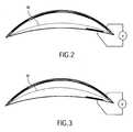
- Figs. 2 and 3there are shown two different configurations of the variable focal length lens of Fig. 1 .
- Figs. 2 and 3have been simplified, to only show the basic shape of the container formed by the transparent front wall 120 and transparent rear wall 110 and the curvature of the meniscus layer M.
- a minimum or zero voltageis applied to the two electrodes 150, 160 via a voltage source 170 and that in this low voltage state the meniscus layer M has the curvature shown and which is determined simply by the interfacial, tension between the first and second fluids.
- an electric fieldis applied between the two electrodes 150, 160 to change the shape of the boundary between the two fluids.
- the applied electric fieldchanges the shape of the meniscus M between the two fluids into the shape shown in Fig. 3 and the focal length of the lens shown is thereby changed.
- the applied electric fieldcauses the contact angle between the periphery of the meniscus level and the point at which it touches the ring-type electrode 150 to change. Because of the change in contact angle, the overall shape of the meniscus layer 140 changes curvature.
- Fig. 3Whilst in Fig. 3 , there is shown to be a degree of change in the diameter, this occurs at the front wall 110 and is outside of the field of view of the user and is only a secondary effect brought about by a change in contact angle of the meniscus layer.
- the radius of curvature of the meniscus Mdecreases and thereby varies the focal length of the lens as a whole and increases the power of the lens.
- the glasses 200comprise lenses 100A, 100B, a frame 210, arms 220, a focal length determiner 230, an adjustment knob 240 and a housing 250, here shown mounted centrally on a bridge portion of the frame.
- FIG. 5there is shown a schematic diagram illustrating the interrelationship between the electronic component parts of the glasses of Fig. 4 .
- the potential difference supplied by the voltage sourcemay be positive, negative or AC.
- the frequency thereofis arranged to be much higher than the first resonant frequency of the meniscus.
- the focal length determiner 230may comprise an infra-red unit of the type employed on auto focus cameras, or an ultrasonic unit for instance.
- the lens strength determiner 290may comprise a unit for measuring the capacitance of each lens.
- a look-up table or the like(not shown) be employed which stores the relationship between capacitance of the lens and lens strength and provides a measure of lens strength to the control unit 280.
- the focal length determiner 230, adjustment knob 240 (which may comprise a potentiometer), lens strength determiner 290 and power supply unit Vare connected to the control unit 280, and the control unit 280 provides a variable output potential O to pairs of electrodes 150, 160 of the lenses 100A, 100B.
- the output of the variable potentiometer 240may be fed directly to the output O of the control unit 280 to provide a directly user adjustable regulation of the focal length of the lenses 100A, 100B.
- the focal length determiner 230may sense the distance of an object that the user is presumed to be looking at.
- the focal length determiner 230is an ultrasonic transducer
- turning the head towards an object to be focused onmay be arranged to target that object with the centrally mounted transducer 230.
- the reflected range finding signal from the transducer 230is processed by the control unit 280 to determine the desired focal length of the glasses, the signal from the lens strength determiner is analyzed to check the actual lens strength and an appropriate output signal "O" is generated to supply an appropriate potential difference between electrodes 150,160 to bring about auto-focusing. It can be checked then once again that the desired lens strength has been achieved and, if needed, the signal "O" may be adjusted.
- closed loop feedback control for adjustment of lens strengthmay be provided and may be particularly useful to compensate for variations in strength encountered due to temperature changes etc.
- Adjustment of focal lengthmay be manual or automatic. Automatic arrangements may be simple (two focal lengths switched between according to a range finding result as to whether an object being looked at is relatively close or relatively far away) or complex (infinitely variable dependent on specific object distance) according to requirements.
- Vibrations of the meniscusmay be suppressed or eliminated by appropriate choice of viscosity of the fluids used. Higher viscosity gives fewer vibrations.
- the electrode 150may be divided into many small electrodes perpendicular to the ring in order to create an anamorphic (e.g. cylindrical) interface. This method to make anamorphic lenses is described in filing NL021187 . However, anamorphic (e.g. cylindric) compensation may also be obtained by preshaping the front and/or rear wall.
- anamorphice.g. cylindric
Landscapes
- Physics & Mathematics (AREA)
- General Physics & Mathematics (AREA)
- Optics & Photonics (AREA)
- Health & Medical Sciences (AREA)
- Ophthalmology & Optometry (AREA)
- General Health & Medical Sciences (AREA)
- Eyeglasses (AREA)
- Mechanical Light Control Or Optical Switches (AREA)
- Liquid Crystal (AREA)
- Non-Portable Lighting Devices Or Systems Thereof (AREA)
- Electrochromic Elements, Electrophoresis, Or Variable Reflection Or Absorption Elements (AREA)
Abstract
Description
- The present invention relates to variable focus spectacles and lenses for them.
- Many people suffer from myopia. Often, as people get older they start suffering from hyperopia as well. A common solution for this problem is to wear varifocus glasses in which the focal length of a lens changes from top to bottom. However, many people do not like wearing such glasses, preferring instead to have separate pairs.
- Naturally, it is inconvenient to need to switch between different pairs of glasses and, clearly, the currently available varifocus lenses do not meet with universal approval. They are often found to be irritating to the user, since it may be necessary to change the way that the user views an object (e.g. tilting the head) in order to view the object through an appropriate part of the varifocus lens.
US 6,369,954 discloses a variable focus lens comprising a chamber filled with a conductive first liquid, a drop of an insulating second liquid being disposed at rest on a region of a first surface of an insulating wall of the chamber, the first and second liquids being non miscible, of different optical indexes and of substantially the same density. The lens comprises means for applying a voltage between the first liquid and an electrode placed on a second surface of the wall to control the shape of the drop.- It is an aim of embodiments of the present invention to provide variable focus lenses suitable for use in glasses and to provide glasses incorporating such lenses.
- According to the invention, there are provided variable focus spectacles comprising a spectacle frame and at least one variable power lens, wherein said lens comprises a transparent rear wall, a transparent front wall, a hydrophobic insulator positioned behind the transparent front wall, a cavity formed between the transparent front wall and the transparent rear wall, first and second immiscible fluids of differing refractive index contained within said cavity, and electrodes to which a potential difference may be applied to change a contact angle between an interface layer of the two fluids and the front wall of the lens,
the transparent front wall joining the transparent rear wall at peripheral regions thereof to form an acute internal angle at their joining region,
the surface of the hydrophobic insulator building a part of the inner surface of the cavity is concave,
the part of the rear wall building a part of the inner surface of the cavity is convex,
wherein the first fluid is the fluid nearest the transparent front wall, whilst the second fluid is the fluid having a boundary with the transparent rear wall and the first fluid comprises a substantially non-conductive fluid, whilst the second fluid comprises a substantially conducting and or polar fluid,
wherein the electrodes comprise a ring-type electrode which extends around an internal periphery of the transparent front wall, so as to form a first electrical contact and a further electrode adjacent an internal surface of the rear wall and the ring-type electrode is insulated and hydrophobic. - Spectacles as formed above enable the user to have adaptive eyesight correction in a single pair of spectacles, avoiding the necessity for changing pairs and further allowing such correction to occur within an extended field of view as compared to known varifocus (bifocal) lenses.
- The transparent front wall joining with the transparent rear wall at peripheral regions thereof to form an acute internal angle at their joining region facilitates the provision of relatively thin lenses.
- Preferably, the first and second fluids are of substantially identical specific gravity. In this manner an interface free from gravitational variations is provided.
- Preferably, the ring-type electrode is coated with an insulator and does not make direct contact with either fluid. The further electrode preferably is arranged to make direct or capacitively coupled contact with the second fluid. In the ease where the second fluid comprises water, the insulator is preferably hydrophobic to avoid problems caused by water molecules sticking to the ring-type electrode.
- Preferably, the first fluid comprises a substantially non-conductive fluid, further referred to as an oil, whilst the second fluid comprises a substantially conducting and or polar fluid, further referred to as an electrolyte.
- Preferably, the second fluid comprises a water/salt mixture having a refractive index different to the refractive index of the first fluid.
- The variable focus spectacles may further comprise adjustment means for adjusting the strength of an electric field to be applied between the electrodes. Such adjustment means allows a user to vary at will the strength of correction.
- Preferably, the adjustment means comprises manual adjustment means and may comprise a variable resistor.
- The adjustment means may comprise automatic adjustment means for varying the focal length of the spectacles dependent upon a perceived distance of an object to be viewed. Such automatic adjustment means may comprise a focal length determiner, a control unit and a power supply V, wherein a range finding signal from the foeal length determiner is processed by the control unit to determine the desired focal length of the glasses and an appropriate output signal is passed to the electrodes to bring about auto-focusing. Such an automatic system has advantages in that it may free the user from the need to manually adjust the lenses whenever a variation in eyesight correction is desired.
- Preferably, the focal length determiner comprises a transducer mounted on the spectacle frame.
- The spectacles may further comprise lens strength determining means for measuring the strength of the lenses.
- For a better understanding of the invention, and to show how embodiments of the same may be carried into effect, reference will now be made, by way of example, to the accompanying diagrammatic drawings in which:
Fig. 1 shows schematically a variable focus lens according to an embodiment of the present invention;Fig. 2 and Fig. 3 illustrate different states of the lens ofFig. 1 ;Fig. 4 shows an example of a pair of glasses incorporating lenses in accordance withFigs. 1 through 3 ; andFig. 5 is a schematic block diagram illustrating an auto-focus mechanism for the glasses ofFig. 4 .- Referring to
Fig. 1 , there is shown avariable focus lens 100 in accordance with an embodiment of the invention. - The
variable focus lens 100 comprises a transparentrear wall 110, atransparent front wall 120, ahydrophobic insulator 130, positioned behind thetransparent front wall 120, acavity 140 formed between the transparentrear wall 110 and thehydrophobic insulator 130 within which a pair of fluids (described later) are contained, a ring-type electrode 150 which extends around an internal periphery of thetransparent front wall 120, so as to form a first electrical contact, acounter electrode 160 forming a second electrode, and avoltage source 170 for providing a variable voltage between the twoelectrodes - Here, it should be noted that the
electrode 150 is insulated and hydrophobic. The inside of thefrontwall 120 does not have to be insulated, but should preferably be hydrophobic in order to prevent that water molecules start sticking to it. Thishydrophobic layer 130 on thefrontwall 120 may therefore be much thinner than the layer covering theelectrode 150. - As mentioned previously, the
cavity 140 is filled with first and second fluids. These fluids are immiscible and of different refractive index. A meniscus line M is shown inFig. 1 denoting the boundary between the first and second fluids. Here, the first fluid is the fluid nearest the transparent front wall, whilst the second fluid is the fluid having a boundary with the transparentrear wall 110. Here, the first fluid may comprise an oil (such as a colorless transparent silicone oil) and the second fluid is an electrolyte such as a water/alcohol/salt mixture having a refractive index less than the refractive index of the first fluid. - In the above construction, it will be appreciated that the
transparent front wall 120 and transparentrear wall 110 form, between them, a container. Thehydrophobic insulator 130 may form a layer internally of the transparentfront wall 120. Thecounter electrode 160 is provided within the container, adjacent to an inside wall of the transparentrear wall 110, so as to enable it to contact the second fluid, whilst thewall electrode 150 extends in a ring around the side of thetransparent front wall 120. - The transparent
rear wall 110 is transparent and may be formed of acrylic resin. Similarly, the transparentfront wall 120 may have the same structure. The twoelectrodes - The
walls - The
hydrophobic insulator 130 preferably forms a coating which is internal of thetransparent front wall 120 and may comprise one of a number of water repellent surfaces. - In accordance with the "electro-wetting" phenomenon, which is well known, applying a voltage between the two
electrodes lens 100. Making thetransparent front wall 120 to be curved as shown, and including thewall electrode 150 in a sloping fashion adjacent thetransparent front wall 120 enables a very compact structure ofvariable focus lens 100 to be achieved. Here, thetransparent front wall 120 of the lens joins with the transparentrear wall 110 at peripheral regions thereof to form an acute internal angle Ø at their joining region, this angle Ø is preferably in the range of zero to ninety degrees. - Referring now to
Figs. 2 and 3 , there is shown, in practice, how thevariable focus lens 100 ofFig. 1 can be arranged to provide variable focusing. - Referring now to
Figs. 2 and 3 , there are shown two different configurations of the variable focal length lens ofFig. 1 . Figs. 2 and 3 have been simplified, to only show the basic shape of the container formed by thetransparent front wall 120 and transparentrear wall 110 and the curvature of the meniscus layer M. Here, in the configuration shown inFig. 1 , it is assumed that a minimum or zero voltage is applied to the twoelectrodes voltage source 170 and that in this low voltage state the meniscus layer M has the curvature shown and which is determined simply by the interfacial, tension between the first and second fluids.- In
Fig. 3 , an electric field is applied between the twoelectrodes Fig. 3 and the focal length of the lens shown is thereby changed. In more detail, The applied electric field causes the contact angle between the periphery of the meniscus level and the point at which it touches the ring-type electrode 150 to change. Because of the change in contact angle, the overall shape of themeniscus layer 140 changes curvature. - Whilst in
Fig. 3 , there is shown to be a degree of change in the diameter, this occurs at thefront wall 110 and is outside of the field of view of the user and is only a secondary effect brought about by a change in contact angle of the meniscus layer. In other words, the radius of curvature of the meniscus M decreases and thereby varies the focal length of the lens as a whole and increases the power of the lens. - Referring now to
Fig. 4 , there is shown a pair ofglasses 200 incorporating lenses of the type above described. Theglasses 200 compriselenses frame 210,arms 220, afocal length determiner 230, anadjustment knob 240 and ahousing 250, here shown mounted centrally on a bridge portion of the frame. - Referring now to
Fig. 5 , there is shown a schematic diagram illustrating the interrelationship between the electronic component parts of the glasses ofFig. 4 . - In
fig. 5 , there is shown schematically afocal length determiner 230,adjustment knob 240,control unit 280, lens strength determiner 290 and power supply V. Here, the potential difference supplied by the voltage source may be positive, negative or AC. In the case of an AC applied voltage, the frequency thereof is arranged to be much higher than the first resonant frequency of the meniscus. - The
focal length determiner 230 may comprise an infra-red unit of the type employed on auto focus cameras, or an ultrasonic unit for instance. - The lens strength determiner 290 may comprise a unit for measuring the capacitance of each lens. Here, a look-up table or the like (not shown) be employed which stores the relationship between capacitance of the lens and lens strength and provides a measure of lens strength to the
control unit 280. - The
focal length determiner 230, adjustment knob 240 (which may comprise a potentiometer), lens strength determiner 290 and power supply unit V are connected to thecontrol unit 280, and thecontrol unit 280 provides a variable output potential O to pairs ofelectrodes lenses variable potentiometer 240 may be fed directly to the output O of thecontrol unit 280 to provide a directly user adjustable regulation of the focal length of thelenses focal length determiner 230 may sense the distance of an object that the user is presumed to be looking at. Here, for instance, where thefocal length determiner 230 is an ultrasonic transducer, turning the head towards an object to be focused on may be arranged to target that object with the centrally mountedtransducer 230. The reflected range finding signal from thetransducer 230 is processed by thecontrol unit 280 to determine the desired focal length of the glasses, the signal from the lens strength determiner is analyzed to check the actual lens strength and an appropriate output signal "O" is generated to supply an appropriate potential difference between electrodes 150,160 to bring about auto-focusing. It can be checked then once again that the desired lens strength has been achieved and, if needed, the signal "O" may be adjusted. - Whilst the above describes open loop type control, it will be appreciated that closed loop feedback control for adjustment of lens strength may be provided and may be particularly useful to compensate for variations in strength encountered due to temperature changes etc.
- From the above, it will be evident to the skilled man that there is described a convenient glasses arrangement by which a user may alter the focal length of their spectacles at will to avoid the need for separate pairs. Adjustment of focal length may be manual or automatic. Automatic arrangements may be simple (two focal lengths switched between according to a range finding result as to whether an object being looked at is relatively close or relatively far away) or complex (infinitely variable dependent on specific object distance) according to requirements.
- Vibrations of the meniscus may be suppressed or eliminated by appropriate choice of viscosity of the fluids used. Higher viscosity gives fewer vibrations.
- The above-described embodiments are non-limiting and the skilled man will realize that numerous modifications may be made without going beyond the scope of the invention.
- The
electrode 150 may be divided into many small electrodes perpendicular to the ring in order to create an anamorphic (e.g. cylindrical) interface. This method to make anamorphic lenses is described in filingNL021187
Claims (10)
- Variable focus spectacles comprising a spectacle frame and at least one variable power lens, wherein said lens comprises a transparent rear wall (110), a transparent front wall (120), a hydrophobic insulator (130) positioned behind the transparent front wall (120), a cavity (140) formed between the transparent front wall (120) and the transparent rear wall (110), first and second immiscible fluids of differing refractive index contained within said cavity, and electrodes (150, 160) to which a potential difference may be applied to change a contact angle between an interface layer of the two fluids and the front wall of the lens,
the transparent front wall (120) joining the transparent rear wall (110) at peripheral regions thereof to form an acute internal angle at their joining region,
the surface of the hydrophobic insulator (130) building a part of the inner surface of the cavity (140) is concave,
the part of the rear wall (110) building a part of the inner surface of the cavity (140) is convex,
wherein the first fluid is the fluid nearest the transparent front wall (120), whilst the second fluid is the fluid having a boundary with the transparent rear wall (110) and the first fluid comprises a substantially non-conductive fluid, whilst the second fluid comprises a substantially conducting and or polar fluid,
wherein the electrodes comprise a ring-type electrode (150) which extends around an internal periphery of the transparent front wall (120), so as to form a first electrical contact and a further electrode (160) being arranged to make direct or capacitively coupled contact with the second fluid and the ring-type electrode (150) is insulated and hydrophobic. - The variable focus spectacles of claim 1, wherein the first and second fluids are of substantially identical specific gravity.
- The variable focus spectacles of claim 1 or 2, wherein the second fluid comprises a water/salt mixture having a refractive index different to the refractive index of the first fluid.
- The variable focus spectacles of any preceding claim, further comprising adjustment means for adjusting the strength of an electric field to be applied between the electrodes (150,160).
- The variable focus spectacles of claim 4, wherein the adjustment means comprises manual adjustment means.
- The variable focus spectacles of claim 5, wherein the manual adjustment means comprises a variable resistor.
- The variable focus spectacles of claim 4, 5 or 6, wherein the adjustment means comprises automatic adjustment means for varying the focal length of the spectacles dependent upon a perceived distance of an object to be viewed.
- The variable focus spectacles of claim 7, wherein the automatic adjustment means comprises a focal length determiner (230), a control unit (280) and a power supply V, wherein a reflected range finding signal from the focal length determiner (230) is processed by the control unit (280) to determine the desired focal length of the glasses and an appropriate output signal is passed to the electrodes (150,160) to bring about auto-focusing.
- The variable focus spectacles of claim 8, wherein the focal length determiner (230) comprises a transducer mounted on the spectacle frame.
- The variable focus spectacles of any of claims 4 to 9, further comprising lens strength determining means for measuring the strength of the lenses (100A, 100B).
Priority Applications (1)
| Application Number | Priority Date | Filing Date | Title |
|---|---|---|---|
| EP04744448AEP1646907B1 (en) | 2003-07-08 | 2004-07-01 | Variable focus spectacles |
Applications Claiming Priority (3)
| Application Number | Priority Date | Filing Date | Title |
|---|---|---|---|
| EP03102047 | 2003-07-08 | ||
| PCT/IB2004/051079WO2005003842A1 (en) | 2003-07-08 | 2004-07-01 | Variable focus spectacles |
| EP04744448AEP1646907B1 (en) | 2003-07-08 | 2004-07-01 | Variable focus spectacles |
Publications (2)
| Publication Number | Publication Date |
|---|---|
| EP1646907A1 EP1646907A1 (en) | 2006-04-19 |
| EP1646907B1true EP1646907B1 (en) | 2008-11-05 |
Family
ID=33560870
Family Applications (1)
| Application Number | Title | Priority Date | Filing Date |
|---|---|---|---|
| EP04744448AExpired - LifetimeEP1646907B1 (en) | 2003-07-08 | 2004-07-01 | Variable focus spectacles |
Country Status (7)
| Country | Link |
|---|---|
| US (1) | US7553019B2 (en) |
| EP (1) | EP1646907B1 (en) |
| JP (1) | JP2007519016A (en) |
| CN (1) | CN100476513C (en) |
| AT (1) | ATE413622T1 (en) |
| DE (1) | DE602004017616D1 (en) |
| WO (1) | WO2005003842A1 (en) |
Families Citing this family (39)
| Publication number | Priority date | Publication date | Assignee | Title |
|---|---|---|---|---|
| DE102004017283A1 (en)* | 2004-04-07 | 2005-11-03 | Carl Zeiss | Artificial lens for an eye |
| US7413306B2 (en)* | 2004-11-18 | 2008-08-19 | Amo Manufacturing Usa, Llc | Sphero cylindrical eye refraction system using fluid focus electrostatically variable lenses |
| GB0425399D0 (en) | 2004-11-18 | 2004-12-22 | Koninkl Philips Electronics Nv | Light intensity measuring method and electronic device |
| DE102005005933A1 (en)* | 2005-02-09 | 2006-08-17 | Carl Zeiss Meditec Ag | Variable optics |
| FR2888954B1 (en)* | 2005-07-20 | 2008-02-08 | Essilor Int | OPTICAL COMPONENT TRANSPORTS TO CELLS SEPARATED BY WALLS |
| US8027095B2 (en) | 2005-10-11 | 2011-09-27 | Hand Held Products, Inc. | Control systems for adaptive lens |
| GB0621065D0 (en)* | 2006-10-23 | 2006-11-29 | Silver Joshua D | Variable focus lens and spectacles |
| US7864440B2 (en) | 2006-11-24 | 2011-01-04 | Varioptic, S.A. | Optical lens with variable focal length |
| US7813047B2 (en) | 2006-12-15 | 2010-10-12 | Hand Held Products, Inc. | Apparatus and method comprising deformable lens element |
| US8027096B2 (en) | 2006-12-15 | 2011-09-27 | Hand Held Products, Inc. | Focus module and components with actuator polymer control |
| US8922902B2 (en)* | 2010-03-24 | 2014-12-30 | Mitsui Chemicals, Inc. | Dynamic lens |
| US11061252B2 (en) | 2007-05-04 | 2021-07-13 | E-Vision, Llc | Hinge for electronic spectacles |
| US10613355B2 (en) | 2007-05-04 | 2020-04-07 | E-Vision, Llc | Moisture-resistant eye wear |
| KR20110015569A (en)* | 2008-04-23 | 2011-02-16 | 다르마틸레케 사만 | Variable Optical Systems and Components |
| JP2012508593A (en)* | 2008-11-12 | 2012-04-12 | コーニンクレッカ フィリップス エレクトロニクス エヌ ヴィ | Acoustic switch and catheter with acoustic switch |
| JP5246666B2 (en)* | 2009-05-11 | 2013-07-24 | パナソニック株式会社 | Multifocal electronic glasses |
| GB201006913D0 (en)* | 2010-04-26 | 2010-06-09 | Taylor Richard | Refractive eyewear |
| US9182521B2 (en) | 2010-05-14 | 2015-11-10 | Johnson & Johnson Vision Care, Inc. | Liquid meniscus lens including variable voltage zones |
| US8743467B2 (en)* | 2010-06-29 | 2014-06-03 | Johnson & Johnson Vision Care, Inc. | Lens with conical frustum meniscus wall |
| US8665526B2 (en)* | 2010-05-14 | 2014-03-04 | Johnson & Johnson Vision Care, Inc. | Arcuate liquid meniscus lens |
| US12436411B2 (en) | 2010-07-02 | 2025-10-07 | E-Vision Optics, Llc | Moisture-resistant eye wear |
| US8638501B2 (en)* | 2010-07-27 | 2014-01-28 | Johnson & Johnson Vision Care, Inc. | Liquid meniscus lens with convex torus-segment meniscus wall |
| US8634145B2 (en)* | 2010-07-29 | 2014-01-21 | Johnson & Johnson Vision Care, Inc. | Liquid meniscus lens with concave torus-segment meniscus wall |
| US8767308B2 (en)* | 2010-08-23 | 2014-07-01 | Johnson & Johnson Vision Care, Inc | Negative add liquid meniscus lens |
| US8474976B2 (en) | 2010-10-30 | 2013-07-02 | Thang Duong | Automatic accommodative spectacles using sensors and focusing elements |
| US8628193B2 (en) | 2010-11-20 | 2014-01-14 | Yibin TIAN | Automatic accommodative spectacles using a scene analyzer and focusing elements |
| US8867141B2 (en)* | 2011-03-18 | 2014-10-21 | Johnson & Johnson Vision Care, Inc. | Lens with multi-concave meniscus wall |
| US20130050448A1 (en)* | 2011-08-24 | 2013-02-28 | Ati Technologies Ulc | Method, circuitry and system for better integrating multiview-based 3d display technology with the human visual system |
| JP5255152B1 (en)* | 2012-07-19 | 2013-08-07 | 孝郎 林 | Variable focus glasses |
| JP5255166B1 (en)* | 2013-02-14 | 2013-08-07 | 孝郎 林 | Variable focus glasses |
| EP2901918B1 (en)* | 2014-02-03 | 2017-05-03 | Parrot Drones | Methods and devices for interactive adjustment of a parameter of a continuously variable optical lens |
| EP2952850A1 (en)* | 2014-06-03 | 2015-12-09 | Optotune AG | Optical device, particularly for tuning the focal length of a lens of the device by means of optical feedback |
| CN106501886A (en)* | 2016-11-23 | 2017-03-15 | 重庆大学 | A kind of smooth thermal coupling zoom gas lens combination |
| CN106950721B (en)* | 2017-05-23 | 2019-03-01 | 京东方科技集团股份有限公司 | A kind of glasses |
| JP7026925B2 (en) | 2017-06-13 | 2022-03-01 | 株式会社エルシオ | glasses |
| CN107166295B (en)* | 2017-07-27 | 2019-11-29 | 温岭市海奔光电科技股份有限公司 | Liquid variant distance-light switching system |
| US11191636B2 (en) | 2017-08-22 | 2021-12-07 | Verily Life Sciences Llc | Electrowetting lenses having oleophobic surfaces |
| US11304796B2 (en) | 2017-09-25 | 2022-04-19 | Verily Life Sciences Llc | Reinforcement ring for intraocular lens |
| CN109445128B (en)* | 2019-01-02 | 2020-04-07 | 京东方科技集团股份有限公司 | Glasses and method for adjusting incident light of eyes |
Family Cites Families (16)
| Publication number | Priority date | Publication date | Assignee | Title |
|---|---|---|---|---|
| US4756605A (en)* | 1985-02-01 | 1988-07-12 | Olympus Optical Co., Ltd. | Liquid crystal spectacles |
| US5182585A (en) | 1991-09-26 | 1993-01-26 | The Arizona Carbon Foil Company, Inc. | Eyeglasses with controllable refracting power |
| DE4217853A1 (en) | 1992-05-29 | 1993-12-02 | Jenoptik Jena Gmbh | Device to determine subjective refraction of patient - has lens frame fixed to curve refraction index meter, having patient known optimal refraction set before final adjustment |
| FR2791439B1 (en)* | 1999-03-26 | 2002-01-25 | Univ Joseph Fourier | DEVICE FOR CENTERING A DROP |
| FR2769375B1 (en) | 1997-10-08 | 2001-01-19 | Univ Joseph Fourier | VARIABLE FOCAL LENS |
| US5956183A (en) | 1998-05-26 | 1999-09-21 | Epstein; Saul | Field-customizable variable focal length lens |
| US6318857B1 (en) | 1998-12-09 | 2001-11-20 | Asahi Kogaku Kogyo Kabushiki Kaisha | Variable power spectacles |
| US6449081B1 (en) | 1999-06-16 | 2002-09-10 | Canon Kabushiki Kaisha | Optical element and optical device having it |
| WO2001002896A1 (en) | 1999-07-02 | 2001-01-11 | E-Vision, L.L.C. | System, apparatus, and method for reducing birefringence |
| US6288846B1 (en) | 1999-09-24 | 2001-09-11 | Arizona Carbon Foil Co., Inc. | Variable focal-length lens assembly |
| GB0100031D0 (en) | 2001-01-02 | 2001-02-14 | Silver Joshua D | Variable focus optical apparatus |
| US6613146B2 (en) | 2001-01-11 | 2003-09-02 | Illinois Tool Works Inc | Variable spacing strand coating system and modular guide roller therefor |
| DE10106650B4 (en) | 2001-02-12 | 2006-11-02 | Klaus Hoffmann | Binocular optical device, in particular electronic glasses, with an electronic camera for automatic focusing including correction of various vision defects |
| ATE363858T1 (en)* | 2002-12-03 | 2007-06-15 | Koninkl Philips Electronics Nv | EYE EXAMINATION |
| US7245439B2 (en)* | 2003-07-14 | 2007-07-17 | Koninklijke Philips Electronics N.V. | Variable lens |
| EP1728117A1 (en)* | 2004-03-05 | 2006-12-06 | Koninklijke Philips Electronics N.V. | Variable focus lens |
- 2004
- 2004-07-01USUS10/563,841patent/US7553019B2/ennot_activeExpired - Fee Related
- 2004-07-01EPEP04744448Apatent/EP1646907B1/ennot_activeExpired - Lifetime
- 2004-07-01ATAT04744448Tpatent/ATE413622T1/ennot_activeIP Right Cessation
- 2004-07-01CNCN200480019863.8Apatent/CN100476513C/ennot_activeExpired - Fee Related
- 2004-07-01JPJP2006518451Apatent/JP2007519016A/ennot_activeWithdrawn
- 2004-07-01DEDE602004017616Tpatent/DE602004017616D1/ennot_activeExpired - Fee Related
- 2004-07-01WOPCT/IB2004/051079patent/WO2005003842A1/enactiveApplication Filing
Also Published As
| Publication number | Publication date |
|---|---|
| WO2005003842A1 (en) | 2005-01-13 |
| EP1646907A1 (en) | 2006-04-19 |
| DE602004017616D1 (en) | 2008-12-18 |
| ATE413622T1 (en) | 2008-11-15 |
| JP2007519016A (en) | 2007-07-12 |
| US20060244902A1 (en) | 2006-11-02 |
| CN100476513C (en) | 2009-04-08 |
| US7553019B2 (en) | 2009-06-30 |
| CN1823293A (en) | 2006-08-23 |
Similar Documents
| Publication | Publication Date | Title |
|---|---|---|
| EP1646907B1 (en) | Variable focus spectacles | |
| TWI343486B (en) | Variable shape lens | |
| RU2545313C2 (en) | Lens unit filled with liquid with variable focal distance | |
| KR101053707B1 (en) | Spherical-Circular Eye Refractive System Using Electrostatically Variable Fluid Lenses | |
| US11762189B2 (en) | Liquid lenses | |
| US7245439B2 (en) | Variable lens | |
| US20100020285A1 (en) | Optical lens with variable focal length | |
| RU2642159C2 (en) | Binocular magnifier with changed optical force using lens technology of lens filled with liquid | |
| US11662568B2 (en) | Liquid lenses and methods for operating liquid lenses | |
| TW201224527A (en) | Liquid meniscus lens including variable voltage zones | |
| EP1870742B1 (en) | Tri-liquid lens | |
| EP1646908B1 (en) | Sunglasses with adaptable transmissivity | |
| CN115598861B (en) | Ophthalmic lens with dynamic focus control | |
| JPS61156227A (en) | Fresnel liquid crystal spectacle | |
| KR102074694B1 (en) | Auto focusing device | |
| US20120176530A1 (en) | Electrically-Controlled, Variable Focal Length Liquid-Based Optical Imaging Apparatus and Method | |
| WO2009117854A1 (en) | Liquid zoom lens | |
| US11402664B2 (en) | Glasses | |
| KR20200131633A (en) | Variable lens, lens module, and glasses including the same | |
| CN114740555B (en) | A multifunctional liquid lens with adjustable surface shape and aperture | |
| CN215986716U (en) | Detachable augmented reality display equipment | |
| WO2023029099A1 (en) | Lens, glasses, and diopter adjustment method | |
| KR102727446B1 (en) | Glasses | |
| Ivanova | Biomimetic optics | |
| WO2019140936A1 (en) | Glasses |
Legal Events
| Date | Code | Title | Description |
|---|---|---|---|
| PUAI | Public reference made under article 153(3) epc to a published international application that has entered the european phase | Free format text:ORIGINAL CODE: 0009012 | |
| 17P | Request for examination filed | Effective date:20060208 | |
| AK | Designated contracting states | Kind code of ref document:A1 Designated state(s):AT BE BG CH CY CZ DE DK EE ES FI FR GB GR HU IE IT LI LU MC NL PL PT RO SE SI SK TR | |
| DAX | Request for extension of the european patent (deleted) | ||
| 17Q | First examination report despatched | Effective date:20060403 | |
| GRAP | Despatch of communication of intention to grant a patent | Free format text:ORIGINAL CODE: EPIDOSNIGR1 | |
| GRAS | Grant fee paid | Free format text:ORIGINAL CODE: EPIDOSNIGR3 | |
| GRAA | (expected) grant | Free format text:ORIGINAL CODE: 0009210 | |
| AK | Designated contracting states | Kind code of ref document:B1 Designated state(s):AT BE BG CH CY CZ DE DK EE ES FI FR GB GR HU IE IT LI LU MC NL PL PT RO SE SI SK TR | |
| REG | Reference to a national code | Ref country code:GB Ref legal event code:FG4D | |
| REG | Reference to a national code | Ref country code:CH Ref legal event code:EP | |
| REG | Reference to a national code | Ref country code:IE Ref legal event code:FG4D | |
| REF | Corresponds to: | Ref document number:602004017616 Country of ref document:DE Date of ref document:20081218 Kind code of ref document:P | |
| NLV1 | Nl: lapsed or annulled due to failure to fulfill the requirements of art. 29p and 29m of the patents act | ||
| PG25 | Lapsed in a contracting state [announced via postgrant information from national office to epo] | Ref country code:ES Free format text:LAPSE BECAUSE OF FAILURE TO SUBMIT A TRANSLATION OF THE DESCRIPTION OR TO PAY THE FEE WITHIN THE PRESCRIBED TIME-LIMIT Effective date:20090216 Ref country code:AT Free format text:LAPSE BECAUSE OF FAILURE TO SUBMIT A TRANSLATION OF THE DESCRIPTION OR TO PAY THE FEE WITHIN THE PRESCRIBED TIME-LIMIT Effective date:20081105 | |
| PG25 | Lapsed in a contracting state [announced via postgrant information from national office to epo] | Ref country code:FI Free format text:LAPSE BECAUSE OF FAILURE TO SUBMIT A TRANSLATION OF THE DESCRIPTION OR TO PAY THE FEE WITHIN THE PRESCRIBED TIME-LIMIT Effective date:20081105 Ref country code:SI Free format text:LAPSE BECAUSE OF FAILURE TO SUBMIT A TRANSLATION OF THE DESCRIPTION OR TO PAY THE FEE WITHIN THE PRESCRIBED TIME-LIMIT Effective date:20081105 Ref country code:PL Free format text:LAPSE BECAUSE OF FAILURE TO SUBMIT A TRANSLATION OF THE DESCRIPTION OR TO PAY THE FEE WITHIN THE PRESCRIBED TIME-LIMIT Effective date:20081105 Ref country code:NL Free format text:LAPSE BECAUSE OF FAILURE TO SUBMIT A TRANSLATION OF THE DESCRIPTION OR TO PAY THE FEE WITHIN THE PRESCRIBED TIME-LIMIT Effective date:20081105 | |
| PG25 | Lapsed in a contracting state [announced via postgrant information from national office to epo] | Ref country code:BE Free format text:LAPSE BECAUSE OF FAILURE TO SUBMIT A TRANSLATION OF THE DESCRIPTION OR TO PAY THE FEE WITHIN THE PRESCRIBED TIME-LIMIT Effective date:20081105 Ref country code:RO Free format text:LAPSE BECAUSE OF FAILURE TO SUBMIT A TRANSLATION OF THE DESCRIPTION OR TO PAY THE FEE WITHIN THE PRESCRIBED TIME-LIMIT Effective date:20081105 Ref country code:EE Free format text:LAPSE BECAUSE OF FAILURE TO SUBMIT A TRANSLATION OF THE DESCRIPTION OR TO PAY THE FEE WITHIN THE PRESCRIBED TIME-LIMIT Effective date:20081105 Ref country code:BG Free format text:LAPSE BECAUSE OF FAILURE TO SUBMIT A TRANSLATION OF THE DESCRIPTION OR TO PAY THE FEE WITHIN THE PRESCRIBED TIME-LIMIT Effective date:20090205 Ref country code:DK Free format text:LAPSE BECAUSE OF FAILURE TO SUBMIT A TRANSLATION OF THE DESCRIPTION OR TO PAY THE FEE WITHIN THE PRESCRIBED TIME-LIMIT Effective date:20081105 | |
| PG25 | Lapsed in a contracting state [announced via postgrant information from national office to epo] | Ref country code:CZ Free format text:LAPSE BECAUSE OF FAILURE TO SUBMIT A TRANSLATION OF THE DESCRIPTION OR TO PAY THE FEE WITHIN THE PRESCRIBED TIME-LIMIT Effective date:20081105 Ref country code:PT Free format text:LAPSE BECAUSE OF FAILURE TO SUBMIT A TRANSLATION OF THE DESCRIPTION OR TO PAY THE FEE WITHIN THE PRESCRIBED TIME-LIMIT Effective date:20090406 Ref country code:SE Free format text:LAPSE BECAUSE OF FAILURE TO SUBMIT A TRANSLATION OF THE DESCRIPTION OR TO PAY THE FEE WITHIN THE PRESCRIBED TIME-LIMIT Effective date:20090205 | |
| PLBE | No opposition filed within time limit | Free format text:ORIGINAL CODE: 0009261 | |
| STAA | Information on the status of an ep patent application or granted ep patent | Free format text:STATUS: NO OPPOSITION FILED WITHIN TIME LIMIT | |
| PG25 | Lapsed in a contracting state [announced via postgrant information from national office to epo] | Ref country code:SK Free format text:LAPSE BECAUSE OF FAILURE TO SUBMIT A TRANSLATION OF THE DESCRIPTION OR TO PAY THE FEE WITHIN THE PRESCRIBED TIME-LIMIT Effective date:20081105 | |
| 26N | No opposition filed | Effective date:20090806 | |
| PGFP | Annual fee paid to national office [announced via postgrant information from national office to epo] | Ref country code:FR Payment date:20090730 Year of fee payment:6 | |
| PGFP | Annual fee paid to national office [announced via postgrant information from national office to epo] | Ref country code:GB Payment date:20090731 Year of fee payment:6 | |
| PGFP | Annual fee paid to national office [announced via postgrant information from national office to epo] | Ref country code:DE Payment date:20090929 Year of fee payment:6 | |
| PG25 | Lapsed in a contracting state [announced via postgrant information from national office to epo] | Ref country code:MC Free format text:LAPSE BECAUSE OF NON-PAYMENT OF DUE FEES Effective date:20090731 | |
| REG | Reference to a national code | Ref country code:CH Ref legal event code:PL | |
| REG | Reference to a national code | Ref country code:IE Ref legal event code:MM4A | |
| PG25 | Lapsed in a contracting state [announced via postgrant information from national office to epo] | Ref country code:LI Free format text:LAPSE BECAUSE OF NON-PAYMENT OF DUE FEES Effective date:20090731 Ref country code:CH Free format text:LAPSE BECAUSE OF NON-PAYMENT OF DUE FEES Effective date:20090731 | |
| PG25 | Lapsed in a contracting state [announced via postgrant information from national office to epo] | Ref country code:IE Free format text:LAPSE BECAUSE OF NON-PAYMENT OF DUE FEES Effective date:20090701 | |
| PG25 | Lapsed in a contracting state [announced via postgrant information from national office to epo] | Ref country code:GR Free format text:LAPSE BECAUSE OF FAILURE TO SUBMIT A TRANSLATION OF THE DESCRIPTION OR TO PAY THE FEE WITHIN THE PRESCRIBED TIME-LIMIT Effective date:20090206 | |
| GBPC | Gb: european patent ceased through non-payment of renewal fee | Effective date:20100701 | |
| PG25 | Lapsed in a contracting state [announced via postgrant information from national office to epo] | Ref country code:IT Free format text:LAPSE BECAUSE OF FAILURE TO SUBMIT A TRANSLATION OF THE DESCRIPTION OR TO PAY THE FEE WITHIN THE PRESCRIBED TIME-LIMIT Effective date:20081105 | |
| REG | Reference to a national code | Ref country code:FR Ref legal event code:ST Effective date:20110331 | |
| PG25 | Lapsed in a contracting state [announced via postgrant information from national office to epo] | Ref country code:LU Free format text:LAPSE BECAUSE OF NON-PAYMENT OF DUE FEES Effective date:20090701 Ref country code:DE Free format text:LAPSE BECAUSE OF NON-PAYMENT OF DUE FEES Effective date:20110201 | |
| REG | Reference to a national code | Ref country code:DE Ref legal event code:R119 Ref document number:602004017616 Country of ref document:DE Effective date:20110201 | |
| PG25 | Lapsed in a contracting state [announced via postgrant information from national office to epo] | Ref country code:FR Free format text:LAPSE BECAUSE OF NON-PAYMENT OF DUE FEES Effective date:20100802 | |
| PG25 | Lapsed in a contracting state [announced via postgrant information from national office to epo] | Ref country code:HU Free format text:LAPSE BECAUSE OF FAILURE TO SUBMIT A TRANSLATION OF THE DESCRIPTION OR TO PAY THE FEE WITHIN THE PRESCRIBED TIME-LIMIT Effective date:20090506 | |
| PG25 | Lapsed in a contracting state [announced via postgrant information from national office to epo] | Ref country code:GB Free format text:LAPSE BECAUSE OF NON-PAYMENT OF DUE FEES Effective date:20100701 | |
| PG25 | Lapsed in a contracting state [announced via postgrant information from national office to epo] | Ref country code:TR Free format text:LAPSE BECAUSE OF FAILURE TO SUBMIT A TRANSLATION OF THE DESCRIPTION OR TO PAY THE FEE WITHIN THE PRESCRIBED TIME-LIMIT Effective date:20081105 | |
| PG25 | Lapsed in a contracting state [announced via postgrant information from national office to epo] | Ref country code:CY Free format text:LAPSE BECAUSE OF FAILURE TO SUBMIT A TRANSLATION OF THE DESCRIPTION OR TO PAY THE FEE WITHIN THE PRESCRIBED TIME-LIMIT Effective date:20081105 |