EP1645232A1 - Device for stocking, delivering and deploying surgical staples - Google Patents
Device for stocking, delivering and deploying surgical staplesDownload PDFInfo
- Publication number
- EP1645232A1 EP1645232A1EP05356178AEP05356178AEP1645232A1EP 1645232 A1EP1645232 A1EP 1645232A1EP 05356178 AEP05356178 AEP 05356178AEP 05356178 AEP05356178 AEP 05356178AEP 1645232 A1EP1645232 A1EP 1645232A1
- Authority
- EP
- European Patent Office
- Prior art keywords
- ejection
- fastener
- bar
- fasteners
- handle
- Prior art date
- Legal status (The legal status is an assumption and is not a legal conclusion. Google has not performed a legal analysis and makes no representation as to the accuracy of the status listed.)
- Granted
Links
Images


Classifications
- A—HUMAN NECESSITIES
- A61—MEDICAL OR VETERINARY SCIENCE; HYGIENE
- A61B—DIAGNOSIS; SURGERY; IDENTIFICATION
- A61B17/00—Surgical instruments, devices or methods
- A61B17/068—Surgical staplers, e.g. containing multiple staples or clamps
- A—HUMAN NECESSITIES
- A61—MEDICAL OR VETERINARY SCIENCE; HYGIENE
- A61B—DIAGNOSIS; SURGERY; IDENTIFICATION
- A61B17/00—Surgical instruments, devices or methods
- A61B17/04—Surgical instruments, devices or methods for suturing wounds; Holders or packages for needles or suture materials
- A61B17/0401—Suture anchors, buttons or pledgets, i.e. means for attaching sutures to bone, cartilage or soft tissue; Instruments for applying or removing suture anchors
- A—HUMAN NECESSITIES
- A61—MEDICAL OR VETERINARY SCIENCE; HYGIENE
- A61B—DIAGNOSIS; SURGERY; IDENTIFICATION
- A61B17/00—Surgical instruments, devices or methods
- A61B2017/00004—(bio)absorbable, (bio)resorbable or resorptive
- A—HUMAN NECESSITIES
- A61—MEDICAL OR VETERINARY SCIENCE; HYGIENE
- A61B—DIAGNOSIS; SURGERY; IDENTIFICATION
- A61B17/00—Surgical instruments, devices or methods
- A61B17/04—Surgical instruments, devices or methods for suturing wounds; Holders or packages for needles or suture materials
- A61B17/0401—Suture anchors, buttons or pledgets, i.e. means for attaching sutures to bone, cartilage or soft tissue; Instruments for applying or removing suture anchors
- A61B2017/0419—H-fasteners
Definitions
- the present inventionrelates to an apparatus for dispensing and laying a coated "I" surgical fastener, for example for fixing parietal and visceral reinforcements, said apparatus and said fastener allowing a non-traumatic placement for the tissues.
- the fasteners described in this documentinclude an anchor bar, a stop bar, and a link bar. They are introduced into the tissues to be fixed by means of a hollow needle, beveled and sharp end which passes through said tissues to deliver the fastener to the place where it must take its function.
- the needlepasses through the flesh and, because of its hollow shape, can cause bleeding and a phenomenon of "coring".
- coringmeans a removal of flesh corresponding to the internal volume of the part of the hollow needle having penetrated into the flesh.
- the apparatus described in this documentpresents risks of hemorrhages.
- the present inventionaims to remedy these problems by proposing an apparatus for dispensing a particular fastener "I" coated, able to deliver said fastener in a non-traumatic manner for the flesh and without causing coring phenomenon and limiting the risks bleeding.
- the present inventionalso relates to a coated "I" surgical attachment comprising an anchor bar, a stop bar and a connecting bar, characterized in that the distal portion of the anchor bar of the fastener is of conical shape and the distal end of this distal portion is of hemispherical shape.
- distal end of a workpiecemeans the end furthest from the user of the apparatus and at the proximal end, the end closest to the user of the apparatus.
- the installation of a fastener with the apparatus according to the inventionis not traumatic for the flesh.
- the ejection gun of the apparatus of the inventionhas a flat distal end which does not incise the flesh or the prosthesis, nor penetrates.
- the ejection gunmay be of metal and attached to the slider-magazine.
- the ejection gunis made of plastic material and is molded body with the magazine slider.
- the surface of the distal end of the ejection barrelis blunted.
- Such a configurationis preferred because such an ejection gun is particularly non-traumatic for the flesh. Such an ejection gun therefore does not cause coring phenomenon. It does not therefore cause the removal of flesh likely to trigger hemorrhages.
- the shape, in cone portion terminated by a hemisphere, and the specific nature of the fastener according to the inventionallow the latter to make their way first through the meshes of the prosthesis without to damage the wires and thus without damaging this prosthesis, and then through human tissue without causing bleeding. The risks of stuffing and haemorrhaging are also avoided.
- the fastener Ais made of biocompatible plastic.
- itis made of bioabsorbable plastic.
- the bioabsorbable plasticis a lactic acid polymer.
- the fastenerslips and spreads the son of the prosthesis without damaging them to provide a passage in the center of the mesh of the prosthesis.
- the assembly according to the inventionstaples a prosthesis at a thin anatomical structure, for example at the level of the ligament of Cooper, whose thickness may be less than 3 mm without the proximity of a solid structure, such as the pubic bone, creating an obstacle.
- a solid structuresuch as the pubic bone
- the fastenerhas a larger space in the human tissues to perform the rotation of the anchor bar when positioning the fastener at the time of its ejection, compared to the case of a prior art apparatus for which a beveled needle also penetrates the tissues.
- the ejection gundoes not have a bevel tip, the fastener can escape the ejection gun more quickly.
- the length of the projecting portion of the ejection gun at the time of ejectionis less than or equal to 3 mm.
- the total length L 'of the fastener (A) in its operating positionis less than or equal to 10.5 mm.
- the total height H of the fastener (A) in its operating positionis less than or equal to 6.1 mm.
- the bulk of the fasteneris minimal. It is thus possible to store, for example, up to twenty fasteners in the slide-magazine.
- the handleis provided with a double anti-return system ensuring proper use of the apparatus and avoiding its jamming.
- the elongated element Ccomprises a step-by-step system capable of moving the fasteners A stored by a pitch P equal to the length L of the stop bar.
- a fastener Athis step-by-step system comprising a rack performing a drawer movement at each ejection and being provided with a slidably mounted shuttle on said rack, this shuttle cooperating with fixed notches of the magazine-slider for move one step P on the rack at each ejection.
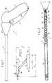
- the apparatus 1 shown in FIG. 1is intended to distribute staples A having, as shown in FIG. 2, the general shape of a coated "I" and composed of two parallel bars, respectively, of anchoring 2 and 3, connected by an inclined connecting bar 4.
- the distal portion 2a of the anchor bar 2is conical. This distal portion 2a may comprise a notch 2b projecting to protect the junction bar-link bar junction which is biased at the time of ejection and implementation of the clip.
- the distal end 2c of the anchor bar 2is hemispherical.
- the distal portion of the anchor bar 2is engaged first in the prosthesis and in the human body. Its particular shape described above allows an easier engagement of the fastener through the prosthesis and the human tissues.
- the hemispherical portion combined with the conical portionallows the clip to provide a passageway through the meshes of the prosthesis by sliding along the wires and spreading them apart without damaging them.
- the distal portion of the anchor bar 2passes through a mesh of the prosthesis without causing resistance or jamming and then easily enters the human tissue through its conical and tapered shape, without, however, traumatize the latter.
- the hemispherical shapeso soft and blunt, its distal end.
- the fastener Ais made of plastics material, in particular a biocompatible material, preferably a bioabsorbable material.
- the connecting bar 4is connected approximately to the center of the anchor bar 2.
- the stop bar 3comprises a distal portion 3a and a proximal portion 3b.
- the connecting bar 4is connected to the stop bar 3 at a point near the center of this stop bar 3, slightly offset towards its proximal portion 3b.
- the link baris inclined at approximately 45 ° to the anchor and stop bars.
- This particular embodiment of the fastenerreduces the size of the fastener while giving it sufficient strength to ensure effective fixation of the prosthesis in the tissues: it is thus possible both to use this fastener to staple structures anatomical thin and store a large number of fasteners within the device 1 as will be seen later.
- the height H of the fastener (A) in its operating position as shown in FIG. 2is preferably less than or equal to 6.1 mm.
- the apparatus 1is composed of two elements, namely a grip assembly B and a longiform element C connected to each other by means of a sleeve D.
- ejection 50(see FIG. 18) being eccentric, the sleeve D makes it possible to pivot the elongated element C and to keep it fixed in rotation in the preferred position of the surgeon to project the ejection gun 50.
- the gripping element Bcomprises a handle body 4 made in two symmetrical parts assembled by ultrasonic welding or by rivets or screws 5, a handle 6 articulated on a transverse axis 7 of the body, a first control lever 8 articulated on a transverse axis 9 of the body and having a cam profile 8a, and a second control lever 10 articulated on a transverse axis 11 of the body and having a cam profile 10a.
- the lower part of the first control lever 8forms a circular arc 12 provided with teeth intended to cooperate with the branch 13 of a wheel 14 articulated on a transverse axis 15 of the body throughout the surgical procedure, namely a phase of positioning of the apparatus during which the surgeon can extract the ejection gun 50 (see Figure 18) without proceeding with the ejection itself, then an ejection phase and finally a resting phase of the device, as will be explained later.
- the wheel 14comprises a second branch 17, retaining, connected to a spring 18 whose fixed end is attached to the handle body 4.
- the arc 12comprises a first series of teeth 19a weak slopes and a second series 19b tooth with steep slopes, the two sets of teeth being separated by a tooth 19c of larger size.
- the elongate element Ccomprises a tubular body 20 in which is slidably mounted a slider-magazine 22.
- the body 20also comprises a step-by-step system whose operation is explained in more detail in FIGS. 4-7.
- the slider-magazine 22is connected to a control rod 24 with an axial rod 21 of smaller diameter bent and contraoudée.
- the control rod 24bears on the cam profile 10a of the second control lever 10.
- the tubular body 20is itself composed of two semi-cylindrical plastic shells assembled in their diametral plane, by welding, nesting or gluing, each of the shells being itself monolithic.
- the body 20is arranged in a not shown metal tubular hoop serving to stiffen the elongate element C.
- the tubular body 20also comprises a piston 25 penetrating into the handle body 4 and held in abutment on the cam profile 8a of the first control lever 8 by means of a spring 27 bearing on a flange 26 of the tubular body 20.
- the piston 25is integral with a tube 38 which passes through it and which also passes through the spring 27.
- the distal end of this tube 38is provided with a flange 39 on which is fixed a push rod 42 s extending into the slider-shop.
- the step-by-step system 23is described in FIG. 3 and in FIG. 4 which is a sectional view through a plane 90 ° offset from the section plane of FIG. 3. It comprises a rack 28, for example metal, provided with notches 29 spaced regularly at a pitch P equal to the length L ( Figure 2) of the stop bar 3 of a fastener A.
- the rack 28is provided at its ends with a distal pad 30 and a proximal pad 31, preferably made of plastic.
- On the rack 28is slidably mounted a shuttle 32, preferably plastic.
- This shuttle 32has a distal tab 33 having an inclined face 34 allowing relative movement, in the proximal direction, of the rack 28 relative to the shuttle 32. This same tab 33 snaps into the notches 29 of the rack 28 to to prevent the relative displacement in the distal direction of the rack 28 relative to the shuttle 32, as shown in FIG. 4.
- the step-by-step system 23also comprises a series of notches 35 formed on the internal face of a shell 20a of the tubular body 20 facing the rack 28 and spaced regularly in a pitch P equal to the length L ( Figure 2) of the stop bar 3 of a fastener A.
- the shuttle 32has a proximal tab 36 having a projection 37 allowing relative movement, in the distal direction, of the shuttle and the rack, relative to the shell 20a. This protrusion 37 snaps into the notches 35 of the shell 20a to prevent the return of the shuttle 32 in the proximal direction.
- an abutment rod 41which extends longitudinally and enters the slide-magazine 22 in the groove 53 (see Figure 18) serving as housing for the stop bars 3 of the fasteners A.
- the slider-magazineis formed by two plastic shells 22a and 22b assembling by gluing or welding, according to their longitudinal and vertical median plane, by enclosing an intermediate plate 22c.
- the shell 22ais integral, at its distal end, with an ejection gun 50.
- This ejection gun 50is hollow and split and the surface of its distal end is disposed in a plane substantially perpendicular to the longitudinal axis of the tubular body 20.
- This ejection gun 50is intended to receive the anchor bar 2 of a fastener A.
- This ejection gun 50is made of plastic and is molded body with the slider-magazine 22.
- the shell 22ahas, near its edges, two longitudinal grooves, a groove 52 serving as housing for the anchor bars 2 of the fasteners A, and a groove 53 serving as housing for the stop bars 3 of the same fasteners. These two grooves are in the same vertical plane, distinct from that passing through the ejection gun 50.
- the groove 53 serving as housing for the stop bars 3opens freely from the front end of the shell 22a, while the groove 52 serving as housing for the anchor bars 2 is die on a visible inclined plane Figure 19. The latter promotes the transverse displacement of the anchor bar 2 of the first fastener until the bar comes behind and in the longitudinal axis of the ejection gun, in a housing 55 as shown in Figure 18.
- the shell 22afurther comprises, next to the ejection gun 50, a rib 51 projecting downwards and having, above the exit trajectory of a stop bar of the groove 53 serving as housings for the rods. stop 3, a sloping face 51 a.
- FIG. 19which shows the apparatus in the rest position, shows that, in this position, the push rod 42 is set back from the rear end of the ejection gun 50 to disengage the receiving housing 55 formed in the other shell 22b.
- FIG. 18shows that the receiving housing 55 for the anchor bar 2 of the first fastener is extended downward by one face inclined 56 supporting the connecting bar 4 of the fastener.
- This shell 22balso comprises a semi-cylindrical groove 57 which, with a complementary groove 58 formed in the wafer 22c, forms a guide channel for the push rod 42. This channel is coaxial with the ejection gun 50.
- the proximal end of the shell 22bis connected to the axial rod 21 itself connected to the control rod 24.
- the distal end of the shell 22bis provided, in its part coming under the ejection gun 50, with a transverse finger 59 protruding towards the other shell, having a sloping face 59a and whose usefulness will be specified later.
- the intermediate plate 22chas a width allowing it to be inserted between the grooves 52 and 53 of the shell 22a and a thickness enabling it to form, with this shell 22a, a passageway enabling the passage for the connecting webs 4 to be released.
- the slide-magazine 22 thus formedhas a length allowing it to store for example twenty fasteners A.
- the handle 6When the apparatus is at rest, the handle 6 is in the position shown in FIG. 8, with the control rod 24 resting on the cam profile 10a of the second control lever 10 and the piston 25 resting on the profile in cam 8a of the first control lever.
- the slider-magazine 22is in retracted position in the tubular body 20.
- the ejection gun 50is retracted into the body and the push rod 42 which releases the receiving housing 55 exerts no effort on the anchor bar 2 disposed in this housing.
- the stop bars 3 of the fasteners A waiting in the magazineare in contact with each other, while the stop bar of the last fastener is in the proximity, with or without contact, of the end of the stop rod 41.
- the elongated element C of the apparatusis introduced, with the ejection gun 50 retracted, into a trocar.
- the engagementis carried out to near or even contact with the prosthesis 61 which must be stapled to the human tissue 62, as shown in FIG. 12.
- the surgeonthen has the possibility of projecting the ejection gun 50 without this triggers the ejection of the fastener A, as shown in FIG. 13.
- the surgeonpresses the handle 6.
- the second control lever 10pivots about its axis 11.
- the cam profile 10apresses the rod 24 which moves in the direction distal and push the slide-magazine 22 also in the distal direction by projecting the ejection gun 50, out of the tubular body 20.
- the branch 13 of the wheel 14cooperates with the series of teeth 19a of the arc 12 of the first control lever 8.
- the surgeoncan relax his effort on the handle and return to the rest position.
- the end of the branch 13being rounded, it does not mesh permanently in the weak slopes of the teeth 19a which allow the branch 13 to return to its original position.
- the surgeoncan project the ejection gun 50 and then return it into the tubular body 20 without triggering the ejection of the fastener A. This allows him to test various positions of the apparatus to finally place it ideally with respect to the tissues (61, 62) it must staple.
- the push rod 42is thus moved longitudinally so that its end comes into contact with the proximal end of the anchor bar 2 of the fastener A disposed in the receiving housing 55, and pushes this anchor bar into the ejection gun 50, as shown in Figure 14.
- the movement of the anchor bar 2pulls the connecting bar 4 and the stop bar 3 of the fastener being dispensed.
- the distal end 3a of the stop bar 3abuts against the finger 59, which causes the upward tilting of this bar to straighten it parallel to the reinforcement 61.
- its proximal end 3bencounters the sloping face 51a of the rib 51 which forces this end transversely, so that, during the straightening of the bar 3, this end does not abut against the ejection gun 50 but instead away from it.
- the anchor bar 2advances into the ejection gun 50.
- the link bar 4escapes from it, the bar 2 can begin to switch with the help of the stop bar 3.
- the connecting bar 4the organized movement of the stop bar 3 has the effect of retaining the anchor bar 2 which is thus forced to straighten and anchor in the biological tissue 62, as shown in FIG. 15.
- the apparatus 1according to the invention and its attachment and can staple prostheses at anatomical structures of small thickness.
- the stop bar 3which is substantially parallel to the textile reinforcement 61, slides, by its distal end 3a, on the sloping face 59a of the finger 59 which chase it transversely and releases it.
- the length of the protruding portion of the ejection gun 50 at the time of ejectionmay for example be 3 mm.
- the release of the action on the handle 6allows the spring 27 to recall the magazine-slide 22 and the push rod 42.
- the branch 13 of the wheel 14cooperates with the series of teeth 19a, 19b, 19c to prevent the user from pressing the handle again before the latter has returned to the rest position, as shown in Figure 11.
- This second non-return systemalso avoids improper use of the device and therefore its clogging.
- the circular arc 12 of the first control lever 8, the series of teeth 19a, 19b and 19cform, with the branch 13 of the wheel 14 a double anti-return system ensuring proper use of the device and avoiding cluttering.
- the apparatus 1can be used to carry out the following fixations or be extracted from the human body, as shown in FIG. 17.
- the dispensing means usedallow the anchor bar 2 and the stop bar 3 to straighten to ensure perfect retention of these tissues.
- the receiving housing 55is closed by the push rod 42 and the waiting fasteners retain their position by means of a braking shoe, not shown and secured.
- the slide-magazine 22moves the fasteners in stock towards the front of the apparatus and moves them away from the free end of the stop rod 41, which is not in motion. only on the end of the displacement of the push rod 42.
- the displacement of the abutment rod 41is ensured by the advance of the shuttle 32 on the rack 28.
- the shuttle 32Before use of the apparatus 1, as shown in FIGS. 4 and 5, the shuttle 32 is engaged, both in a notch 35 of the tubular body 20 by means of the projection 37 of its proximal tab 36, and also in a notch 29 of the rack 28 by means of its distal tab 33.
- the piston 25, pushed by the first control lever 8advances in the distal direction, driving with it the tube 38 and the flange 39 of this tube.
- the flange 39comes into contact with the proximal pad 31 of the rack 28 and drives the rack 28 in the distal direction.
- the shuttle 32is held integral with the rack by its distal tab.
- the slider-magazine 22After ejection of the fastener, the slider-magazine 22 is returned by the spring 27 and its proximal end comes into contact with the distal pad 30 of the rack 28. As shown in FIG. 7, the slider-magazine 22 thus causing with it in the proximal direction the rack 28. Given the inclined face 34 of the distal tab 33 of the shuttle 32, the rack 28 moves in the direction proximal to the shuttle 32 which it remains motionless by relative to the tubular body 20 because of its projection 37 engaged in the second notch 35 of this tubular body 20.
- the shuttle 32has progressed on the rack 28 by a pitch P in the distal direction with respect to FIG. 5.
- the stop rod 41which is integral with the shuttle 32 , has also moved a step P with respect to the initial position it occupied.
- the stop bar 3 of the last fastenercomes into contact with the distal end of the stop rod 41 and holds the row of fasteners, while the slider store ends its re-entry into the tubular body 20.
- the anchor bar 2 of the first fastenercomes into contact with the ramp 54, shown in FIG. 19, which ramp transfers it into the receiving housing 55.
- the apparatus which has been described and its attachmentare particularly suitable for stapling prostheses such as parietal reinforcements without trauma to the flesh and without risk of haemorrhage. They are also particularly useful for stapling prostheses at the level of thin anatomical structures such as the Cooper ligament while ensuring a very effective fixation, and this preferably only during the necessary fixing time thanks to the preferably bioabsorbable character of the fasteners. Moreover, the apparatus and the fastener according to the invention can be used with the same efficiency for laparoscopic or open surgical procedures.
Landscapes
- Health & Medical Sciences (AREA)
- Life Sciences & Earth Sciences (AREA)
- Surgery (AREA)
- Molecular Biology (AREA)
- Engineering & Computer Science (AREA)
- Biomedical Technology (AREA)
- Heart & Thoracic Surgery (AREA)
- Medical Informatics (AREA)
- Nuclear Medicine, Radiotherapy & Molecular Imaging (AREA)
- Animal Behavior & Ethology (AREA)
- General Health & Medical Sciences (AREA)
- Public Health (AREA)
- Veterinary Medicine (AREA)
- Rheumatology (AREA)
- Surgical Instruments (AREA)
- Apparatus For Radiation Diagnosis (AREA)
Abstract
Description
Translated fromFrenchLa présente invention concerne un appareil de distribution et de pose d'une attache chirurgicale en « I » couché, par exemple pour fixer des renforts pariétaux et viscéraux, ledit appareil et ladite attache permettant une pose non traumatisante pour les tissus.The present invention relates to an apparatus for dispensing and laying a coated "I" surgical fastener, for example for fixing parietal and visceral reinforcements, said apparatus and said fastener allowing a non-traumatic placement for the tissues.
On connaît déjà de WO03/075773 un appareil de distribution et de pose d'attaches chirurgicales en « I ». Les attaches décrites dans ce document comprennent une barre d'ancrage, une barre d'arrêt et une barrette de liaison. Elles sont introduites dans les tissus à fixer par le moyen d'une aiguille creuse fendue, en biseau et à bout acéré qui traverse lesdits tissus pour délivrer l'attache à l'endroit où elle doit prendre sa fonction. Ainsi, dans ce document, l'aiguille traverse les chairs et, du fait de sa forme creuse, peut provoquer des saignements ainsi qu'un phénomène de « carottage ». Par « carottage », on entend un prélèvement de chair correspondant au volume intérieur de la partie de l'aiguille creuse ayant pénétré dans les chairs. Ainsi, l'appareil décrit dans ce document présente des risques d'hémorragies.Already known from WO03 / 075773 an apparatus for dispensing and installing surgical fasteners "I". The fasteners described in this document include an anchor bar, a stop bar, and a link bar. They are introduced into the tissues to be fixed by means of a hollow needle, beveled and sharp end which passes through said tissues to deliver the fastener to the place where it must take its function. Thus, in this document, the needle passes through the flesh and, because of its hollow shape, can cause bleeding and a phenomenon of "coring". By "coring" means a removal of flesh corresponding to the internal volume of the part of the hollow needle having penetrated into the flesh. Thus, the apparatus described in this document presents risks of hemorrhages.
Par ailleurs, dans WO03/075773, lorsque l'aiguille à pointe en biseau pique le tissu de la prothèse au niveau d'un croisement de fil ou au niveau d'un fil, elle traverse ce ou ces fils, en séparant éventuellement les brins composant les fils, ce qui peut provoquer résistance et bourrage. Cela endommage les fils et donc la prothèse. La résistance provoquée peut également bloquer le mécanisme de l'appareil et le rendre inutilisable.Furthermore, in WO03 / 075773, when the bevel-tipped needle pierces the prosthesis tissue at a thread crossing or at a thread, it passes through this or these threads, possibly separating the strands. component wires, which can cause strength and jamming. This damages the wires and therefore the prosthesis. The resistance caused can also block the mechanism of the device and make it unusable.
Un autre problème rencontré avec l'appareil décrit dans WO03/075773 est que, du fait de la nécessaire pénétration de l'aiguille en biseau dans les chairs, l'appareil ne permet pas d'agrafer une prothèse au niveau d'une structure anatomique de faible épaisseur, c'est-à-dire en particulier d'une épaisseur inférieure à la longueur de la partie d'aiguille traversant les chairs.Another problem encountered with the apparatus described in WO03 / 075773 is that, due to the need to penetrate the bevel needle into the flesh, the apparatus does not allow stapling a prosthesis at an anatomical structure of small thickness, that is to say in particular of a thickness less than the length of the needle portion passing through the flesh.
La présente invention vise à remédier à ces problèmes en proposant un appareil de distribution d'une attache particulière en « I » couché, apte à délivrer ladite attache de façon non traumatisante pour les chairs et sans provoquer de phénomène de carottage et en limitant les risques de saignement.The present invention aims to remedy these problems by proposing an apparatus for dispensing a particular fastener "I" coated, able to deliver said fastener in a non-traumatic manner for the flesh and without causing coring phenomenon and limiting the risks bleeding.
La présente invention porte sur un appareil de stockage, de distribution et de pose d'attaches chirurgicales (A) en « I » couché comprenant un corps de poignée (B) équipé d'au moins un moyen de commande, et un élément longiforme (C), rapporté et fixé sur la poignée, appareil dans lequel l'élément longiforme (C) est composé d'un corps de forme générale tubulaire contenant :
- à proximité de son extrémité distale, un coulisseau-magasin contenant lui-même des attaches en « I » couché ayant une barre d'ancrage, une barre d'arrêt et une barrette de liaison, ledit coulisseau-magasin étant déplaçable dans l'élément longiforme par une tige de commande actionnable par le moyen de commande de la poignée et, d'autre part solidaire d'un canon d'éjection creux, fendu et longitudinal, saillant de l'extrémité distale dudit coulisseau-magasin et pouvant saillir de l'élément longiforme (C),
- dans son corps tubulaire, d'une part, des moyens de distribution une à une des attaches (A) stockées, cette distribution comprenant le transfert de la barre d'ancrage de la première attache dans un logement d'accueil disposé dans le prolongement du canon d'éjection, et d'autre part, un poussoir d'éjection, déplaçable par le moyen de commande de la poignée et disposé dans l'alignement du canon d'éjection pour pousser dans celui-ci la barre d'ancrage de la première attache,
- la partie distale de la barre d'ancrage des attaches (A) est de forme conique et l'extrémité distale de cette partie distale est de forme hémisphérique,
- la surface de l'extrémité distale du canon d'éjection est disposée selon un plan substantiellement perpendiculaire à l'axe longitudinal du corps tubulaire.
- near its distal end, a slide-magazine itself containing coated "I" fasteners having an anchor bar, a stop bar and a link bar, said slide-magazine being movable in the element longiforme by a control rod operable by the control means of the handle and, secondly secured to a hollow, split and longitudinal hollow ejection gun protruding from the distal end of said magazine-slide and being able to protrude from the elongate element (C),
- in its tubular body, on the one hand, means of distribution one by one of the fasteners (A) stored, this distribution comprising the transfer of the anchor bar of the first fastener in a receiving housing arranged in the extension of the ejection gun, and secondly, an ejection pusher, movable by the control means of the handle and arranged in alignment with the ejection gun to push in the latter the anchor bar of the first attachment,
- the distal portion of the anchor bar of the fasteners (A) is of conical shape and the distal end of this distal portion is of hemispherical shape,
- the surface of the distal end of the ejection gun is disposed in a plane substantially perpendicular to the longitudinal axis of the tubular body.
La présente invention porte encore sur une attache chirurgicale en « I » couché comprenant une barre d'ancrage, une barre d'arrêt et une barrette de liaison, caractérisée en ce que la partie distale de la barre d'ancrage de l'attache est de forme conique et l'extrémité distale de cette partie distale est de forme hémisphérique.The present invention also relates to a coated "I" surgical attachment comprising an anchor bar, a stop bar and a connecting bar, characterized in that the distal portion of the anchor bar of the fastener is of conical shape and the distal end of this distal portion is of hemispherical shape.
La présente demande porte encore sur un ensemble comprenant au moins une attache chirurgicale (A) en « I » couché et un appareil de stockage, de distribution et de pose de telles attaches (A), comprenant un corps de poignée (B) équipé d'au moins un moyen de commande, et un élément longiforme (C), rapporté et fixé sur la poignée, appareil dans lequel l'élément longiforme (C) est composé d'un corps de forme générale tubulaire contenant :
- à proximité de son extrémité distale, un coulisseau-magasin contenant lui-même les attaches (A) en « I » couché ayant une barre d'ancrage, une barre d'arrêt et une barrette de liaison, ledit coulisseau-magasin étant déplaçable dans l'élément longiforme par une tige de commande actionnable par le moyen de commande de la poignée et, d'autre part solidaire d'un canon d'éjection creux, fendu et longitudinal, saillant de l'extrémité distale dudit coulisseau-magasin et pouvant saillir de l'élément longiforme (C),
- dans son corps tubulaire, d'une part, des moyens de distribution une à une des attaches (A) stockées, cette distribution comprenant le transfert de la barre d'ancrage de la première attache dans un logement d'accueil disposé dans le prolongement du canon d'éjection, et d'autre part, un poussoir d'éjection, déplaçable par le moyen de commande de la poignée et disposé dans l'alignement du canon d'éjection pour pousser dans celui-ci la barre d'ancrage de la première attache,
- la partie distale de la barre d'ancrage des attaches (A) est de forme conique et l'extrémité distale de cette partie distale est de forme hémisphérique,
- la surface de l'extrémité distale du canon d'éjection est disposée selon un plan substantiellement perpendiculaire à l'axe longitudinal du corps tubulaire.
- near its distal end, a magazine-slider itself containing the coated "I" fasteners (A) having an anchor bar, a stop bar and a connecting bar, said magazine slider being movable in the elongated element by a control rod operable by the control means of the handle and, secondly secured to a hollow, longitudinal and slit ejection gun protruding from the distal end of said magazine slide and capable of protruding from the elongate element (C),
- in its tubular body, on the one hand, means of distribution one by one of the fasteners (A) stored, this distribution comprising the transfer of the anchor bar of the first fastener in a receiving housing arranged in the extension of the ejection gun, and secondly, an ejection pusher, movable by the control means of the handle and arranged in alignment with the ejection gun to push in the latter the anchor bar of the first attachment,
- the distal portion of the anchor bar of the fasteners (A) is of conical shape and the distal end of this distal portion is of hemispherical shape,
- the surface of the distal end of the ejection gun is disposed in a plane substantially perpendicular to the longitudinal axis of the tubular body.
Dans la présente demande, on entend par extrémité distale d'une pièce l'extrémité la plus éloignée de l'utilisateur de l'appareil et par extrémité proximale, l'extrémité la plus proche de l'utilisateur de l'appareil.In the present application, the term "distal end of a workpiece" means the end furthest from the user of the apparatus and at the proximal end, the end closest to the user of the apparatus.
La pose d'une attache avec l'appareil selon l'invention est non traumatisante pour les chairs. En effet, le canon d'éjection de l'appareil de l'invention présente une extrémité distale plate qui n'incise ni les chairs ni la prothèse, ni ne les pénètre.The installation of a fastener with the apparatus according to the invention is not traumatic for the flesh. Indeed, the ejection gun of the apparatus of the invention has a flat distal end which does not incise the flesh or the prosthesis, nor penetrates.
Ainsi, dans une forme de réalisation de l'invention, le canon d'éjection peut être en métal et rapporté sur le coulisseau-magasin.Thus, in one embodiment of the invention, the ejection gun may be of metal and attached to the slider-magazine.
Dans une forme préférée de réalisation de l'invention, le canon d'éjection est en matière plastique et est moulé de corps avec le coulisseau-magasin. De préférence, la surface de l'extrémité distale du canon d'éjection est émoussée. Une telle configuration est préférée car un tel canon d'éjection est particulièrement non traumatisant pour les chairs. Un tel canon d'éjection ne provoque donc pas de phénomène de carottage. II ne provoque donc pas de prélèvement de chair susceptible de déclencher des hémorragies.In a preferred embodiment of the invention, the ejection gun is made of plastic material and is molded body with the magazine slider. Preferably, the surface of the distal end of the ejection barrel is blunted. Such a configuration is preferred because such an ejection gun is particularly non-traumatic for the flesh. Such an ejection gun therefore does not cause coring phenomenon. It does not therefore cause the removal of flesh likely to trigger hemorrhages.
Par ailleurs, la forme, en portion de cône terminée par une demi-sphère, et la nature spécifiques de l'attache selon l'invention permettent à cette dernière de se frayer un passage tout d'abord à travers les mailles de la prothèse sans en endommager les fils et donc sans abîmer cette prothèse, puis ensuite à travers les tissus humains sans provoquer de saignement. Les risques de bourrage et d'hémorragies sont également évités.Furthermore, the shape, in cone portion terminated by a hemisphere, and the specific nature of the fastener according to the invention allow the latter to make their way first through the meshes of the prosthesis without to damage the wires and thus without damaging this prosthesis, and then through human tissue without causing bleeding. The risks of stuffing and haemorrhaging are also avoided.
Dans une forme préférée de réalisation de l'invention, l'attache A est en matière plastique biocompatible. De préférence, elle est réalisée en matière plastique biorésorbable. De préférence encore, la matière plastique biorésorbable est un polymère d'acide lactique.In a preferred embodiment of the invention, the fastener A is made of biocompatible plastic. Preferably, it is made of bioabsorbable plastic. More preferably, the bioabsorbable plastic is a lactic acid polymer.
Grâce à sa nature plastique, l'attache glisse et écarte les fils de la prothèse sans les endommager pour se ménager un passage au centre de la maille de la prothèse.Due to its plastic nature, the fastener slips and spreads the son of the prosthesis without damaging them to provide a passage in the center of the mesh of the prosthesis.
Enfin, il est possible, grâce à l'ensemble selon l'invention d'agrafer une prothèse au niveau d'une structure anatomique de faible épaisseur, par exemple au niveau du ligament de Cooper, dont l'épaisseur peut être inférieure à 3 mm, et ce sans que la proximité d'une structure solide, comme l'os pubien, ne crée un obstacle. En effet, dans le cas où l'attache selon l'invention entre en contact avec l'os pubien, son extrémité hémisphérique lui permet de glisser en douceur sur cet os et de pivoter aisément dans les tissus pour se mettre en place et assurer son rôle de fixation efficace.Finally, it is possible, thanks to the assembly according to the invention to staple a prosthesis at a thin anatomical structure, for example at the level of the ligament of Cooper, whose thickness may be less than 3 mm without the proximity of a solid structure, such as the pubic bone, creating an obstacle. Indeed, in the case where the fastener according to the invention comes into contact with the pubic bone, its hemispherical end allows it to slide smoothly on the bone and pivot easily in the tissues to set up and ensure its effective fastening role.
En effet, avec l'appareil selon l'invention, du fait que le canon d'éjection ne pénètre ni la prothèse, ni les tissus humains, l'attache dispose d'un espace plus important dans les tissus humains pour effectuer la rotation de la barre d'ancrage lors du positionnement de l'attache au moment de son éjection, par rapport au cas d'un appareil de l'art antérieur pour lequel une aiguille en biseau pénètre également dans les tissus. En particulier, selon la présente invention, le canon d'éjection ne présentant pas d'embout en biseau, l'attache peut s'échapper du canon d'éjection plus rapidement.Indeed, with the apparatus according to the invention, because the ejection gun does not penetrate the prosthesis or the human tissues, the fastener has a larger space in the human tissues to perform the rotation of the anchor bar when positioning the fastener at the time of its ejection, compared to the case of a prior art apparatus for which a beveled needle also penetrates the tissues. In particular, according to the present invention, the ejection gun does not have a bevel tip, the fastener can escape the ejection gun more quickly.
Dans une forme préférée de réalisation de l'invention, la longueur de la partie saillante du canon d'éjection au moment de l'éjection est inférieure ou égale à 3 mm.In a preferred embodiment of the invention, the length of the projecting portion of the ejection gun at the time of ejection is less than or equal to 3 mm.
Dans une forme préférée de réalisation de l'invention, la longueur totale L' de l'attache (A) dans sa position de fonctionnement est inférieure ou égale à 10,5 mm.In a preferred embodiment of the invention, the total length L 'of the fastener (A) in its operating position is less than or equal to 10.5 mm.
Dans une forme préférée de réalisation de l'invention, la hauteur totale H de l'attache (A) dans sa position de fonctionnement est inférieure ou égale à 6,1 mm.In a preferred embodiment of the invention, the total height H of the fastener (A) in its operating position is less than or equal to 6.1 mm.
En particulier, selon l'invention, l'encombrement de l'attache est minimal. Il est ainsi possible de stocker par exemple jusqu'à vingt attaches au sein du coulisseau-magasin.In particular, according to the invention, the bulk of the fastener is minimal. It is thus possible to store, for example, up to twenty fasteners in the slide-magazine.
Dans une forme préférée de réalisation de l'invention, la poignée est munie d'un double système anti-retour assurant une utilisation adéquate de l'appareil et évitant son enrayage.In a preferred embodiment of the invention, the handle is provided with a double anti-return system ensuring proper use of the apparatus and avoiding its jamming.
Dans une forme préférée de réalisation de l'invention, l'élément longiforme C comprend un système de pas-à-pas apte à déplacer les attaches A stockées d'un pas P de valeur égale à la longueur L de la barre d'arrêt d'une attache A, ce système de pas-à-pas comprenant une crémaillère effectuant un mouvement de tiroir à chaque éjection et étant munie d'une navette montée coulissante sur cette crémaillère, cette navette coopérant avec des crans fixes du coulisseau-magasin pour progresser d'un pas P sur la crémaillère à chaque éjection.In a preferred embodiment of the invention, the elongated element C comprises a step-by-step system capable of moving the fasteners A stored by a pitch P equal to the length L of the stop bar. a fastener A, this step-by-step system comprising a rack performing a drawer movement at each ejection and being provided with a slidably mounted shuttle on said rack, this shuttle cooperating with fixed notches of the magazine-slider for move one step P on the rack at each ejection.
D'autres caractéristiques et avantages ressortiront de la description qui suit en référence au dessin schématique annexé représentant une forme d'exécution de l'ensemble selon l'invention.
- La figure 1 est une vue de côté d'un appareil selon l'invention au repos ;
- La figure 2 est une vue de côté d'une attache selon l'invention ;
- La figure 3 est une vue en coupe de l'élément longiforme,
- La figure 4 est une vue partielle en coupe montrant le système de pas-à-pas et la navette,
- Les figures 5 à 7 sont des vues partielles en coupe montrant le fonctionnement du système de pas-à-pas,
- La figure 8 est une vue en coupe de la poignée en position de repos,
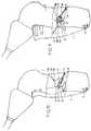
- Les figures 9 à 11 montrent le fonctionnement du double système anti-retour de la poignée,
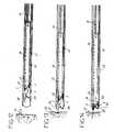
- Les figures 12 à 17 montrent les différentes phases de l'éjection d'une attache avec l'appareil selon l'invention,
- La figure 18 est une vue en perspective éclatée à échelle agrandie de l'extrémité antérieure de l'élément longiforme et du coulisseau-magasin,
- La figure 19 est une vue en coupe de l'extrémité antérieure de l'élément longiforme.
- Figure 1 is a side view of an apparatus according to the invention at rest;
- Figure 2 is a side view of a fastener according to the invention;
- FIG. 3 is a sectional view of the elongated element,
- FIG. 4 is a partial sectional view showing the step-by-step system and the shuttle,
- Figures 5 to 7 are partial sectional views showing the operation of the step-by-step system,
- FIG. 8 is a sectional view of the handle in the rest position,
- Figures 9 to 11 show the operation of the double anti-return system of the handle,
- FIGS. 12 to 17 show the different phases of the ejection of a fastener with the apparatus according to the invention,
- FIG. 18 is an exploded perspective view on an enlarged scale of the anterior end of the elongate element and the magazine slide,
- Figure 19 is a sectional view of the anterior end of the elongate member.
L'appareil 1 représenté à la figure 1 est destiné à distribuer des agrafes A ayant, comme montré à la figure 2, la forme générale d'un « I » couché et composé de deux barres parallèles, respectivement, d'ancrage 2 et d'arrêt 3, reliées par une barrette de liaison inclinée 4. La partie distale 2a de la barre d'ancrage 2 est de forme conique. Cette partie distale 2a peut comprendre un cran 2b en saillie pour protéger la jonction barre d'ancrage-barrette de liaison qui est sollicitée au moment de l'éjection et de la mise en place de l'agrafe. L'extrémité distale 2c de la barre d'ancrage 2 est de forme hémisphérique. La partie distale de la barre d'ancrage 2 est engagée en premier dans la prothèse et dans le corps humain. Sa forme particulière décrite ci-dessus permet un engagement facilité de l'attache à travers la prothèse et les tissus humains. La partie hémisphérique combinée à la partie conique permet à l'attache de se ménager un passage à travers les mailles de la prothèse en glissant le long des fils et en les écartant sans les endommager. Ainsi, la partie distale de la barre d'ancrage 2 passe à travers une maille de la prothèse sans provoquer de résistance ou de bourrage et pénètre ensuite facilement dans les tissus humains grâce à sa forme conique et effilée, sans toutefois traumatiser ces derniers du fait de la forme hémisphérique, donc douce et émoussée, de son extrémité distale.The apparatus 1 shown in FIG. 1 is intended to distribute staples A having, as shown in FIG. 2, the general shape of a coated "I" and composed of two parallel bars, respectively, of anchoring 2 and 3, connected by an inclined connecting
L'attache A est réalisée en matière plastique, notamment en matériau biocompatible, de préférence biorésorbable.The fastener A is made of plastics material, in particular a biocompatible material, preferably a bioabsorbable material.
La barrette de liaison 4 est reliée environ au centre de la barre d'ancrage 2. La barre d'arrêt 3 comprend une partie distale 3a et une partie proximale 3b. La barrette de liaison 4 est reliée à la barre d'arrêt 3 à un point proche du centre de cette barre d'arrêt 3, légèrement décalé vers sa partie proximale 3b. La barrette de liaison est inclinée d'environ 45° par rapport aux barres d'ancrage et d'arrêt. Cette forme particulière de réalisation de l'attache permet de réduire l'encombrement de l'attache tout en lui conférant la solidité suffisante pour assurer une fixation efficace de la prothèse dans les tissus : il est ainsi possible à la fois d'utiliser cette attache pour agrafer des structures anatomiques de faible épaisseur et de stocker un grand nombre d'attaches au sein de l'appareil 1 comme il sera vu plus loin. La longueur totale L' de l'attache (A), dans sa position de fonctionnement telle que représentée à la figure 2, à savoir de l'extrémité distale 2c de sa barre d'ancrage 2 à l'extrémité proximale 3b de sa barre d'arrêt 3, est de préférence inférieure ou égale à 10,5 mm. La hauteur H de l'attache (A), dans sa position de fonctionnement telle que représentée à la figure 2 est de préférence inférieure ou égale à 6,1 mm.The connecting
Comme montré à la figure 1, l'appareil 1 est composé de deux éléments, à savoir un ensemble de préhension B et un élément longiforme C reliés l'un à l'autre à l'aide d'une douille D. Le canon d'éjection 50 (voir figure 18) étant excentré, la douille D permet de faire pivoter l'élément longiforme C et de le maintenir fixe en rotation dans la position préférée du chirurgien pour faire saillir le canon d'éjection 50.As shown in FIG. 1, the apparatus 1 is composed of two elements, namely a grip assembly B and a longiform element C connected to each other by means of a sleeve D. ejection 50 (see FIG. 18) being eccentric, the sleeve D makes it possible to pivot the elongated element C and to keep it fixed in rotation in the preferred position of the surgeon to project the
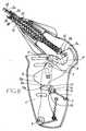
Comme montré à la figure 8, l'élément de préhension B comprend un corps de poignée 4 réalisé en deux parties symétriques assemblées par soudage à ultrasons ou par des rivets ou vis 5, une poignée 6 articulée sur un axe transversal 7 du corps, un premier levier de commande 8 articulé sur un axe transversal 9 du corps et présentant un profil en came 8a, et un deuxième levier de commande 10 articulé sur un axe transversal 11 du corps et présentant un profil en came 10a.As shown in FIG. 8, the gripping element B comprises a
La partie inférieure du premier levier de commande 8 forme un arc de cercle 12 muni de dents destinées à coopérer avec la branche 13 d'une molette 14 articulée sur un axe transversal 15 du corps tout au long du geste chirurgical, à savoir une phase de positionnement de l'appareil au cours de laquelle le chirurgien peut faire sortir le canon d'éjection 50 (voir figure 18) sans procéder à l'éjection elle-même, puis une phase d'éjection et enfin une phase de retour au repos de l'appareil, comme cela sera expliqué plus loin. La molette 14 comprend une deuxième branche 17, de retenue, reliée à un ressort 18 dont l'extrémité fixe est attachée au corps de poignée 4. L'arc de cercle 12 comprend une première série de dents 19a à pentes faibles et une deuxième série de dents 19b à pentes fortes, les deux séries de dents étant séparées par une dent 19c de taille supérieure.The lower part of the
Comme montré figure 3, l'élément longiforme C comprend un corps tubulaire 20 dans lequel est monté coulissant un coulisseau-magasin 22. Le corps 20 comprend également un système de pas-à-pas 23 dont le fonctionnement est expliqué plus en détails aux figures 4 à 7.As shown in FIG. 3, the elongate element C comprises a
Comme montré à la figure 4, le coulisseau-magasin 22 est relié à une tige de commande 24 à l'aide d'une tige axiale 21 de plus petit diamètre coudée et contrecoudée. Comme montré à la figure 8, la tige de commande 24 prend appui sur le profil en came 10a du deuxième levier de commande 10. Le corps tubulaire 20 est lui-même composé de deux coquilles semi cylindriques en matière plastique assemblées dans leur plan diamétral, par soudure, emboîtage ou collage, chacune des coquilles étant elle-même monolithique. De préférence, le corps 20 est disposé dans une frette tubulaire métallique non représentée servant à rigidifier l'élément longiforme C.As shown in Figure 4, the slider-
Comme montré figure 8, le corps tubulaire 20 comprend également un piston 25 pénétrant dans le corps de poignée 4 et maintenu en appui sur le profil en came 8a du premier levier de commande 8 au moyen d'un ressort 27 prenant appui sur une collerette 26 du corps tubulaire 20. Le piston 25 est solidaire d'un tube 38 qui le traverse et qui traverse également le ressort 27. L'extrémité distale de ce tube 38 est munie d'une collerette 39 sur laquelle est fixée une tige poussoir 42 s'étendant dans le coulisseau-magasin.As shown in FIG. 8, the
Le système de pas-à-pas 23 est décrit sur la figure 3 et sur la figure 4 qui est une vue en coupe par un plan décalé de 90° par rapport au plan de coupe de la figure 3. Il comprend une crémaillère 28, par exemple en métal, munie d'encoches 29 espacées régulièrement selon un pas P de valeur égale à la longueur L (figure 2) de la barre d'arrêt 3 d'une attache A. La crémaillère 28 est munie à ses extrémités d'un patin distal 30 et d'un patin proximal 31, de préférence en matière plastique. Sur la crémaillère 28, est montée coulissante une navette 32, de préférence en matière plastique. Cette navette 32 comporte une patte distale 33 présentant une face inclinée 34 autorisant le déplacement relatif, dans le sens proximal, de la crémaillère 28 par rapport à la navette 32. Cette même patte 33 s'encliquète dans les encoches 29 de la crémaillère 28 pour empêcher le déplacement relatif dans le sens distal, de la crémaillère 28 par rapport à la navette 32, comme montré à la figure 4.The step-by-step system 23 is described in FIG. 3 and in FIG. 4 which is a sectional view through a plane 90 ° offset from the section plane of FIG. 3. It comprises a
Le système de pas-à-pas 23 comprend également une série de crans 35 ménagés sur la face interne d'une coquille 20a du corps tubulaire 20 en regard de la crémaillère 28 et espacés régulièrement selon un pas P de valeur égale à la longueur L (figure 2) de la barre d'arrêt 3 d'une attache A. La navette 32 comporte une patte proximale 36 présentant une saillie 37 autorisant le déplacement relatif, dans le sens distal, de la navette et de la crémaillère, par rapport à la coquille 20a. Cette saillie 37 s'encliquète dans les crans 35 de la coquille 20a pour empêcher le retour de la navette 32 dans le sens proximal.The step-by-step system 23 also comprises a series of
Sur la navette 32 est montée une tige de butée 41 qui s'étend longitudinalement et pénètre dans le coulisseau-magasin 22 dans la rainure 53 (voir figure 18) servant de logements aux barres d'arrêt 3 des attaches A.On the
Comme montré à la figure 18, le coulisseau-magasin est formé par deux coquilles en matière plastique 22a et 22b s'assemblant par collage ou soudure, selon leur plan médian longitudinal et vertical, en enserrant une plaquette intercalaire 22c.As shown in Figure 18, the slider-magazine is formed by two
La coquille 22a est solidaire, à son extrémité distale, d'un canon d'éjection 50. Ce canon d'éjection 50 est creux et fendu et la surface de son extrémité distale est disposée selon un plan substantiellement perpendiculaire à l'axe longitudinal du corps tubulaire 20. Ce canon d'éjection 50 est destiné à recevoir la barre d'ancrage 2 d'une attache A. Ce canon d'éjection 50 est en matière plastique et est moulé de corps avec le coulisseau-magasin 22.The
La coquille 22a comporte, près de ses bords, deux rainures longitudinales, une rainure 52, servant de logements aux barres d'ancrage 2 des attaches A, et une rainure 53 servant de logements aux barres d'arrêt 3 des mêmes attaches. Ces deux rainures sont dans un même plan vertical, distinct de celui passant par le canon d'éjection 50. La rainure 53 servant de logements aux barres d'arrêt 3 débouche librement de l'extrémité antérieure de la coquille 22a, tandis que la rainure 52 servant de logements aux barres d'ancrage 2 vient mourir sur un plan incliné visible figure 19. Ce dernier favorise le déplacement transversal de la barre d'ancrage 2 de la première attache jusqu'à ce que cette barre vienne derrière et dans l'axe longitudinal du canon d'éjection, dans un logement d'accueil 55 comme montré à la figure 18.The
La coquille 22a comporte encore, à côté du canon d'éjection 50, une nervure 51 saillant vers le bas et présentant, au-dessus de la trajectoire de sortie d'une barre d'arrêt de la rainure 53 servant de logements aux barres d'arrêt 3, une face pentue 51 a.The
La figure 19, qui représente l'appareil en position de repos, montre que, dans cette position, la tige poussoir 42 est en retrait de l'extrémité postérieure du canon d'éjection 50 pour dégager le logement d'accueil 55 ménagé dans l'autre coquille 22b.FIG. 19, which shows the apparatus in the rest position, shows that, in this position, the
La figure 18 montre que le logement d'accueil 55 pour la barre d'ancrage 2 de la première attache est prolongé vers le bas par une face inclinée 56 de soutien de la barrette de liaison 4 de l'attache. Cette coquille 22b comporte également une rainure semi cylindrique 57 qui, avec une rainure complémentaire 58 ménagée dans la plaquette 22c, forme un canal de guidage pour la tige poussoir 42. Ce canal est coaxial au canon d'éjection 50. L'extrémité proximale de la coquille 22b est liée à la tige axiale 21 elle-même reliée à la tige de commande 24. L'extrémité distale de la coquille 22b est munie, dans sa partie venant sous le canon d'éjection 50, d'un doigt transversal 59 saillant en direction de l'autre coquille, présentant une face pentue 59a et dont l'utilité sera précisée ultérieurement.FIG. 18 shows that the receiving
La plaquette intercalaire 22c a une largeur lui permettant de s'insérer entre les rainures 52 et 53 de la coquille 22a et une épaisseur lui permettant de former, avec cette coquille 22a, un couloir permettant de libérer le passage pour les barrettes de liaison 4 des attaches A.The intermediate plate 22c has a width allowing it to be inserted between the
Le coulisseau-magasin 22 ainsi formé a une longueur lui permettant de stocker par exemple vingt attaches A.The slide-
Lorsque l'appareil est au repos, la poignée 6 est dans la position représentée à la figure 8, avec la tige de commande 24 en appui sur le profil en came 10a du deuxième levier de commande 10 et le piston 25 en appui sur le profil en came 8a du premier levier de commande. Le coulisseau-magasin 22 est en position rétractée dans le corps tubulaire 20. Le canon d'éjection 50 est rétracté dans le corps et la tige poussoir 42 qui dégage le logement d'accueil 55 n'exerce aucun effort sur la barre d'ancrage 2 disposée dans ce logement. De même, les barres d'arrêt 3 des attaches A en attente dans le magasin sont en contact les unes avec les autres, tandis que la barre d'arrêt de la dernière attache est à proximité, avec ou sans contact, de l'extrémité de la tige de butée 41.When the apparatus is at rest, the
En utilisation, par exemple par voie laparoscopique, l'élément longiforme C de l'appareil est introduit, avec le canon d'éjection 50 rentré, dans un trocart. L'engagement est effectué jusqu'à proximité, voire contact avec la prothèse 61 qu'il faut agrafer aux tissus humains 62, comme montré sur la figure 12. Le chirurgien a alors la possibilité de faire saillir le canon d'éjection 50 sans pour cela déclencher l'éjection de l'attache A, comme montré sur la figure 13. Pour ce faire, le chirurgien presse la poignée 6. Sur une première partie de la course, le deuxième levier de commande 10 pivote autour de son axe 11. Le profil en came 10a appuie sur la tige 24 qui se déplace dans le sens distal et pousse le coulisseau-magasin 22 également dans le sens distal en faisant saillir le canon d'éjection 50, hors du corps tubulaire 20.In use, for example laparoscopically, the elongated element C of the apparatus is introduced, with the
Durant cette première partie de course également, la branche 13 de la molette 14 coopère avec la série de dents 19a de l'arc de cercle 12 du premier levier de commande 8. Tant que la branche 13 n'a pas dépassé la dent de taille supérieure 19c, le chirurgien peut relâcher son effort sur la poignée et revenir à la position de repos. En effet, l'extrémité de la branche 13 étant arrondie, elle ne s'engrène pas de façon définitive dans les pentes faibles des dents 19a qui autorisent ainsi la branche 13 à retourner à sa position initiale. Ainsi, tant qu'il n'exerce pas un effort suffisant pour dépasser la dent 19a, le chirurgien peut faire saillir le canon d'éjection 50 puis le faire à nouveau rentrer dans le corps tubulaire 20 sans déclencher l'éjection de l'attache A. Cela lui permet de tester divers positionnements de l'appareil pour le placer finalement idéalement par rapport aux tissus (61, 62) qu'il doit agrafer.During this first part of the race as well, the
Une fois que le chirurgien a suffisamment pesé sur la poignée 6 pour que la branche 13 de la molette 14 dépasse la dent 19c, le retour en arrière n'est plus possible comme montré sur la figure 9. Sur cette figure, la branche 13 de la molette 14 est bloquée contre la dent de taille supérieure 19c. Durant la deuxième partie de course, le chirurgien doit procéder à l'éjection de l'attache. Pour éviter une utilisation mal adaptée de l'appareil, qui pourrait conduire à son enrayage, le geste du chirurgien est guidé jusqu'à sa complète réalisation. Ainsi, durant cette deuxième partie de course, la branche 13 de la molette 14 coopère avec la série de dents à pentes fortes 19b pour permettre la progression du geste, dent par dent, tout en empêchant le relâchement de la poignée et donc le retour en arrière. Ainsi, le chirurgien est obligé d'appuyer sur la poignée jusqu'à la fin de sa course, comme montré à la figure 10 pour libérer la branche 13 des dents 19b et ainsi déclencher l'éjection de l'attache A.Once the surgeon has sufficiently weighed on the
Durant cette deuxième partie de course, le deuxième levier de commande 10 a provoqué le déplacement du piston 25, donc du tube 38 et de la tige poussoir 42, le déplacement de la tige poussoir 42 s'effectuant par rapport au coulisseau-magasin 22 qui reste temporairement fixe.During this second part of the race, the
La tige poussoir 42 est donc déplacée longitudinalement afin que son extrémité vienne en contact avec l'extrémité proximale de la barre d'ancrage 2 de l'attache A disposée dans le logement d'accueil 55, et pousse cette barre d'ancrage dans le canon d'éjection 50, comme montré à la figure 14.The
Le déplacement de la barre d'ancrage 2 tire la barrette de liaison 4 et la barre d'arrêt 3 de l'attache en cours de distribution. L'extrémité distale 3a de la barre d'arrêt 3 vient en butée contre le doigt 59, ce qui provoque le basculement vers le haut de cette barre jusqu'à la redresser parallèlement au renfort 61. Durant ce mouvement, son extrémité proximale 3b rencontre la face pentue 51a de la nervure 51 qui chasse transversalement cette extrémité, afin que, lors du redressement de la barre 3, cette extrémité ne vienne pas buter contre le canon d'éjection 50 mais au contraire s'en éloigne.The movement of the
Durant ce mouvement, la barre d'ancrage 2 avance dans le canon d'éjection 50. Quand la barrette de liaison 4 échappe de celle-ci, la barre 2 peut commencer à basculer avec l'aide de la barre d'arrêt 3. En effet, par la barrette de liaison 4, le mouvement organisé de la barre d'arrêt 3 a pour conséquence de retenir la barre d'ancrage 2 qui est ainsi forcée à se redresser et à s'ancrer dans les tissus biologiques 62, comme montré à la figure 15. Du fait de la forme non biseautée du canon d'éjection 50 et du faible encombrement de la barre d'ancrage 2, cette dernière s'échappe rapidement du canon d'éjection 50 et n'a ensuite besoin que de peu d'espace pour effectuer son redressement et sa rotation comme montré sur les figures 15 et 16. L'appareil 1 selon l'invention et son attache permettent ainsi d'agrafer des prothèses au niveau de structures anatomiques de faible épaisseur.During this movement, the
Enfin, pendant ou en fin de redressement de la barre d'ancrage 2, la barre d'arrêt 3 qui est sensiblement parallèle au renfort textile 61, glisse, par son extrémité distale 3a, sur la face pentue 59a du doigt 59 qui la chasse transversalement et la libère.Finally, during or at the end of straightening of the anchoring
La longueur de la partie saillante du canon d'éjection 50 au moment de l'éjection peut par exemple être de 3 mm.The length of the protruding portion of the
A la fin de ce mouvement, et comme montré à la figure 16, le relâchement de l'action sur la poignée 6 permet au ressort 27 de rappeler le coulisseau-magasin 22 et la tige poussoir 42. Durant le relâchement de la poignée 6, la branche 13 de la molette 14 coopère avec les séries de dents 19a, 19b, 19c pour empêcher l'utilisateur d'appuyer de nouveau sur la poignée avant que cette dernière ne soit revenue en position de repos, comme montré sur la figure 11. Ce deuxième système anti-retour permet d'éviter là aussi une utilisation mal adaptée de l'appareil et donc son enrayage. L'arc de cercle 12 du premier levier de commande 8, les séries de dents 19a, 19b et 19c forment, avec la branche 13 de la molette 14 un double système anti-retour assurant une utilisation adéquate de l'appareil et évitant son enrayage.At the end of this movement, and as shown in Figure 16, the release of the action on the
Une fois la poignée 6 revenue en position de repos, l'appareil 1 peut être utilisé pour procéder aux fixations suivantes ou être extrait du corps humain, comme montré figure 17.Once the
Pendant la distribution de l'attache A, les moyens de distribution mis en oeuvre permettent à la barre d'ancrage 2 et à la barre d'arrêt 3 de se redresser pour assurer une parfaite retenue de ces tissus.During the distribution of the fastener A, the dispensing means used allow the
Pendant la phase de distribution de la première attache A, comme montré aux figures 14 à 16, le logement d'accueil 55 est obturé par la tige poussoir 42 et les attaches en attente conservent leur position grâce à un patin de freinage non représenté et solidaire du coulisseau-magasin 22. Le déplacement du coulisseau-magasin 22 vers l'avant de l'appareil emmène avec lui les attaches en stock et les éloigne de l'extrémité libre de la tige de butée 41, qui n'est mise en mouvement que sur la fin du déplacement de la tige poussoir 42.During the dispensing phase of the first fastener A, as shown in FIGS. 14 to 16, the receiving
Comme montré aux figures 5 à 7, le déplacement de la tige de butée 41 est assuré par l'avancée de la navette 32 sur la crémaillère 28.As shown in FIGS. 5 to 7, the displacement of the
Avant utilisation de l'appareil 1, comme montré sur les figures 4 et 5, la navette 32 est enclenchée, à la fois dans un cran 35 du corps tubulaire 20 au moyen de la saillie 37 de sa patte proximale 36, et également dans une encoche 29 de la crémaillère 28 au moyen de sa patte distale 33. Au moment de l'éjection de l'attache, le piston 25, poussé par le premier levier de commande 8, avance dans le sens distal, entraînant avec lui le tube 38 et la collerette 39 de ce tube. Comme montré à la figure 6, la collerette 39 entre en contact avec le patin proximal 31 de la crémaillère 28 et entraîne dans le sens distal cette crémaillère 28. Lors de ce déplacement, la navette 32 est maintenue solidaire de la crémaillère par sa patte distale 33 enclenchée dans l'encoche 29 de la crémaillère tandis que sa patte proximale 36 se défléchit pour permettre à la saillie 37 de passer le cran 35 du corps tubulaire 20 dans lequel elle était enclenchée et d'aller s'enclencher dans le cran 35 suivant. Ainsi, la navette 32 ainsi que la tige de butée 41 qui en est solidaire progressent dans le sens distal de la longueur d'un pas P.Before use of the apparatus 1, as shown in FIGS. 4 and 5, the
Après éjection de l'attache, le coulisseau-magasin 22 est rappelé par le ressort 27 et son extrémité proximale entre en contact avec le patin distal 30 de la crémaillère 28. Comme montré à la figure 7, le coulisseau-magasin 22 entraîne ainsi avec lui dans le sens proximal la crémaillère 28. Compte tenu de la face inclinée 34 de la patte distale 33 de la navette 32, la crémaillère 28 se déplace dans le sens proximal par rapport à la navette 32 qui elle, reste immobile par rapport au corps tubulaire 20 du fait de sa saillie 37 enclenchée dans le deuxième cran 35 de ce corps tubulaire 20.After ejection of the fastener, the slider-
Ainsi, sur la figure 7, la navette 32 a progressé sur la crémaillère 28 d'un pas P dans le sens distal par rapport à la figure 5. Il résulte de cela que la tige de butée 41, qui est solidaire de la navette 32, a également avancé d'un pas P par rapport à la position initiale qu'elle occupait. De la sorte, lors du recul du coulisseau-magasin 22, la barre d'arrêt 3 de la dernière attache vient en contact avec l'extrémité distale de la tige de butée 41 et retient la rangée d'attaches, tandis que le coulisseau-magasin termine sa rentrée dans le corps tubulaire 20.Thus, in FIG. 7, the
En fin de rentrée du coulisseau-magasin, la barre d'ancrage 2 de la première attache vient en contact avec la rampe 54, montrée figure 19, rampe qui assure son transfert dans le logement d'accueil 55.At the end of the return of the magazine-magazine, the
L'appareil qui a été décrit et son attache sont particulièrement adaptés pour agrafer des prothèses telles que des renforts pariétaux sans traumatisme des chairs et sans risque d'hémorragies. Ils sont aussi particulièrement utiles pour agrafer des prothèses au niveau de structures anatomiques de faible épaisseur comme par exemple le ligament de Cooper tout en assurant une fixation très efficace, et ce de préférence seulement pendant le temps nécessaire de fixation grâce au caractère de préférence biorésorbable des attaches. Par ailleurs, l'appareil et l'attache selon l'invention peuvent être utilisés avec la même efficacité pour des interventions chirurgicales par voie laparoscopique ou au contraire par voie ouverte.The apparatus which has been described and its attachment are particularly suitable for stapling prostheses such as parietal reinforcements without trauma to the flesh and without risk of haemorrhage. They are also particularly useful for stapling prostheses at the level of thin anatomical structures such as the Cooper ligament while ensuring a very effective fixation, and this preferably only during the necessary fixing time thanks to the preferably bioabsorbable character of the fasteners. Moreover, the apparatus and the fastener according to the invention can be used with the same efficiency for laparoscopic or open surgical procedures.
Claims (12)
Translated fromFrenchApplications Claiming Priority (1)
| Application Number | Priority Date | Filing Date | Title |
|---|---|---|---|
| FR0410585AFR2876020B1 (en) | 2004-10-06 | 2004-10-06 | APPARATUS FOR STORAGE, DISTRIBUTION AND INSTALLATION OF SURGICAL ATTACHES |
Publications (2)
| Publication Number | Publication Date |
|---|---|
| EP1645232A1true EP1645232A1 (en) | 2006-04-12 |
| EP1645232B1 EP1645232B1 (en) | 2008-12-31 |
Family
ID=34952214
Family Applications (1)
| Application Number | Title | Priority Date | Filing Date |
|---|---|---|---|
| EP05356178ANot-in-forceEP1645232B1 (en) | 2004-10-06 | 2005-09-28 | Device for stocking, delivering and deploying surgical staples |
Country Status (8)
| Country | Link |
|---|---|
| US (1) | US7833234B2 (en) |
| EP (1) | EP1645232B1 (en) |
| JP (1) | JP4965105B2 (en) |
| AT (1) | ATE418918T1 (en) |
| DE (1) | DE602005012033D1 (en) |
| ES (1) | ES2319551T3 (en) |
| FR (1) | FR2876020B1 (en) |
| WO (1) | WO2006037893A1 (en) |
Cited By (15)
| Publication number | Priority date | Publication date | Assignee | Title |
|---|---|---|---|---|
| US9554887B2 (en) | 2011-03-16 | 2017-01-31 | Sofradim Production | Prosthesis comprising a three-dimensional and openworked knit |
| US9622843B2 (en) | 2011-07-13 | 2017-04-18 | Sofradim Production | Umbilical hernia prosthesis |
| US9750837B2 (en) | 2012-09-25 | 2017-09-05 | Sofradim Production | Haemostatic patch and method of preparation |
| US9839505B2 (en) | 2012-09-25 | 2017-12-12 | Sofradim Production | Prosthesis comprising a mesh and a strengthening means |
| US9931198B2 (en) | 2015-04-24 | 2018-04-03 | Sofradim Production | Prosthesis for supporting a breast structure |
| US9980802B2 (en) | 2011-07-13 | 2018-05-29 | Sofradim Production | Umbilical hernia prosthesis |
| US10070948B2 (en) | 2008-06-27 | 2018-09-11 | Sofradim Production | Biosynthetic implant for soft tissue repair |
| US10080639B2 (en) | 2011-12-29 | 2018-09-25 | Sofradim Production | Prosthesis for inguinal hernia |
| US10184032B2 (en) | 2015-02-17 | 2019-01-22 | Sofradim Production | Method for preparing a chitosan-based matrix comprising a fiber reinforcement member |
| US10363690B2 (en) | 2012-08-02 | 2019-07-30 | Sofradim Production | Method for preparing a chitosan-based porous layer |
| US10646321B2 (en) | 2016-01-25 | 2020-05-12 | Sofradim Production | Prosthesis for hernia repair |
| US10675137B2 (en) | 2017-05-02 | 2020-06-09 | Sofradim Production | Prosthesis for inguinal hernia repair |
| US10682215B2 (en) | 2016-10-21 | 2020-06-16 | Sofradim Production | Method for forming a mesh having a barbed suture attached thereto and the mesh thus obtained |
| US10743976B2 (en) | 2015-06-19 | 2020-08-18 | Sofradim Production | Synthetic prosthesis comprising a knit and a non porous film and method for forming same |
| US12064330B2 (en) | 2020-04-28 | 2024-08-20 | Covidien Lp | Implantable prothesis for minimally invasive hernia repair |
Families Citing this family (544)
| Publication number | Priority date | Publication date | Assignee | Title |
|---|---|---|---|---|
| US20070084897A1 (en) | 2003-05-20 | 2007-04-19 | Shelton Frederick E Iv | Articulating surgical stapling instrument incorporating a two-piece e-beam firing mechanism |
| US9060770B2 (en) | 2003-05-20 | 2015-06-23 | Ethicon Endo-Surgery, Inc. | Robotically-driven surgical instrument with E-beam driver |
| US11998198B2 (en) | 2004-07-28 | 2024-06-04 | Cilag Gmbh International | Surgical stapling instrument incorporating a two-piece E-beam firing mechanism |
| US8215531B2 (en) | 2004-07-28 | 2012-07-10 | Ethicon Endo-Surgery, Inc. | Surgical stapling instrument having a medical substance dispenser |
| US7354447B2 (en) | 2005-11-10 | 2008-04-08 | Ethicon Endo-Surgery, Inc. | Disposable loading unit and surgical instruments including same |
| US9072535B2 (en) | 2011-05-27 | 2015-07-07 | Ethicon Endo-Surgery, Inc. | Surgical stapling instruments with rotatable staple deployment arrangements |
| US11890012B2 (en) | 2004-07-28 | 2024-02-06 | Cilag Gmbh International | Staple cartridge comprising cartridge body and attached support |
| US7669746B2 (en) | 2005-08-31 | 2010-03-02 | Ethicon Endo-Surgery, Inc. | Staple cartridges for forming staples having differing formed staple heights |
| US9237891B2 (en) | 2005-08-31 | 2016-01-19 | Ethicon Endo-Surgery, Inc. | Robotically-controlled surgical stapling devices that produce formed staples having different lengths |
| US10159482B2 (en) | 2005-08-31 | 2018-12-25 | Ethicon Llc | Fastener cartridge assembly comprising a fixed anvil and different staple heights |
| US7673781B2 (en) | 2005-08-31 | 2010-03-09 | Ethicon Endo-Surgery, Inc. | Surgical stapling device with staple driver that supports multiple wire diameter staples |
| US11246590B2 (en) | 2005-08-31 | 2022-02-15 | Cilag Gmbh International | Staple cartridge including staple drivers having different unfired heights |
| US7500979B2 (en) | 2005-08-31 | 2009-03-10 | Ethicon Endo-Surgery, Inc. | Surgical stapling device with multiple stacked actuator wedge cams for driving staple drivers |
| US11484312B2 (en) | 2005-08-31 | 2022-11-01 | Cilag Gmbh International | Staple cartridge comprising a staple driver arrangement |
| US8800838B2 (en) | 2005-08-31 | 2014-08-12 | Ethicon Endo-Surgery, Inc. | Robotically-controlled cable-based surgical end effectors |
| US7934630B2 (en) | 2005-08-31 | 2011-05-03 | Ethicon Endo-Surgery, Inc. | Staple cartridges for forming staples having differing formed staple heights |
| US7467740B2 (en) | 2005-09-21 | 2008-12-23 | Ethicon Endo-Surgery, Inc. | Surgical stapling instruments having flexible channel and anvil features for adjustable staple heights |
| US7407078B2 (en) | 2005-09-21 | 2008-08-05 | Ehthicon Endo-Surgery, Inc. | Surgical stapling instrument having force controlled spacing end effector |
| US7673783B2 (en) | 2005-11-04 | 2010-03-09 | Ethicon Endo-Surgery, Inc. | Surgical stapling instruments structured for delivery of medical agents |
| US7607557B2 (en) | 2005-11-04 | 2009-10-27 | Ethicon Endo-Surgery, Inc. | Surgical stapling instruments structured for pump-assisted delivery of medical agents |
| US7328828B2 (en) | 2005-11-04 | 2008-02-12 | Ethicon Endo-Surgery, Inc, | Lockout mechanisms and surgical instruments including same |
| US20070106317A1 (en) | 2005-11-09 | 2007-05-10 | Shelton Frederick E Iv | Hydraulically and electrically actuated articulation joints for surgical instruments |
| US7673780B2 (en) | 2005-11-09 | 2010-03-09 | Ethicon Endo-Surgery, Inc. | Articulation joint with improved moment arm extension for articulating an end effector of a surgical instrument |
| US7799039B2 (en) | 2005-11-09 | 2010-09-21 | Ethicon Endo-Surgery, Inc. | Surgical instrument having a hydraulically actuated end effector |
| US7670334B2 (en) | 2006-01-10 | 2010-03-02 | Ethicon Endo-Surgery, Inc. | Surgical instrument having an articulating end effector |
| US11278279B2 (en) | 2006-01-31 | 2022-03-22 | Cilag Gmbh International | Surgical instrument assembly |
| US7766210B2 (en) | 2006-01-31 | 2010-08-03 | Ethicon Endo-Surgery, Inc. | Motor-driven surgical cutting and fastening instrument with user feedback system |
| US7464849B2 (en) | 2006-01-31 | 2008-12-16 | Ethicon Endo-Surgery, Inc. | Electro-mechanical surgical instrument with closure system and anvil alignment components |
| US8763879B2 (en) | 2006-01-31 | 2014-07-01 | Ethicon Endo-Surgery, Inc. | Accessing data stored in a memory of surgical instrument |
| US20120292367A1 (en) | 2006-01-31 | 2012-11-22 | Ethicon Endo-Surgery, Inc. | Robotically-controlled end effector |
| US7845537B2 (en) | 2006-01-31 | 2010-12-07 | Ethicon Endo-Surgery, Inc. | Surgical instrument having recording capabilities |
| US11224427B2 (en) | 2006-01-31 | 2022-01-18 | Cilag Gmbh International | Surgical stapling system including a console and retraction assembly |
| US7568603B2 (en) | 2006-01-31 | 2009-08-04 | Ethicon Endo-Surgery, Inc. | Motor-driven surgical cutting and fastening instrument with articulatable end effector |
| US7416101B2 (en) | 2006-01-31 | 2008-08-26 | Ethicon Endo-Surgery, Inc. | Motor-driven surgical cutting and fastening instrument with loading force feedback |
| US8708213B2 (en) | 2006-01-31 | 2014-04-29 | Ethicon Endo-Surgery, Inc. | Surgical instrument having a feedback system |
| US9861359B2 (en) | 2006-01-31 | 2018-01-09 | Ethicon Llc | Powered surgical instruments with firing system lockout arrangements |
| US8820603B2 (en) | 2006-01-31 | 2014-09-02 | Ethicon Endo-Surgery, Inc. | Accessing data stored in a memory of a surgical instrument |
| US20110295295A1 (en) | 2006-01-31 | 2011-12-01 | Ethicon Endo-Surgery, Inc. | Robotically-controlled surgical instrument having recording capabilities |
| US11793518B2 (en) | 2006-01-31 | 2023-10-24 | Cilag Gmbh International | Powered surgical instruments with firing system lockout arrangements |
| US7575144B2 (en) | 2006-01-31 | 2009-08-18 | Ethicon Endo-Surgery, Inc. | Surgical fastener and cutter with single cable actuator |
| US8161977B2 (en) | 2006-01-31 | 2012-04-24 | Ethicon Endo-Surgery, Inc. | Accessing data stored in a memory of a surgical instrument |
| US7422139B2 (en) | 2006-01-31 | 2008-09-09 | Ethicon Endo-Surgery, Inc. | Motor-driven surgical cutting fastening instrument with tactile position feedback |
| US8186555B2 (en) | 2006-01-31 | 2012-05-29 | Ethicon Endo-Surgery, Inc. | Motor-driven surgical cutting and fastening instrument with mechanical closure system |
| US7753904B2 (en) | 2006-01-31 | 2010-07-13 | Ethicon Endo-Surgery, Inc. | Endoscopic surgical instrument with a handle that can articulate with respect to the shaft |
| US20110024477A1 (en) | 2009-02-06 | 2011-02-03 | Hall Steven G | Driven Surgical Stapler Improvements |
| US7464846B2 (en) | 2006-01-31 | 2008-12-16 | Ethicon Endo-Surgery, Inc. | Surgical instrument having a removable battery |
| US7770775B2 (en) | 2006-01-31 | 2010-08-10 | Ethicon Endo-Surgery, Inc. | Motor-driven surgical cutting and fastening instrument with adaptive user feedback |
| US7644848B2 (en) | 2006-01-31 | 2010-01-12 | Ethicon Endo-Surgery, Inc. | Electronic lockouts and surgical instrument including same |
| US8721630B2 (en) | 2006-03-23 | 2014-05-13 | Ethicon Endo-Surgery, Inc. | Methods and devices for controlling articulation |
| US8236010B2 (en) | 2006-03-23 | 2012-08-07 | Ethicon Endo-Surgery, Inc. | Surgical fastener and cutter with mimicking end effector |
| US8992422B2 (en) | 2006-03-23 | 2015-03-31 | Ethicon Endo-Surgery, Inc. | Robotically-controlled endoscopic accessory channel |
| US8322455B2 (en) | 2006-06-27 | 2012-12-04 | Ethicon Endo-Surgery, Inc. | Manually driven surgical cutting and fastening instrument |
| US7431189B2 (en) | 2006-08-02 | 2008-10-07 | Ethicon Endo-Surgery, Inc. | Pneumatically powered surgical cutting and fastening instrument with mechanical linkage coupling end effector and trigger motion |
| US7740159B2 (en) | 2006-08-02 | 2010-06-22 | Ethicon Endo-Surgery, Inc. | Pneumatically powered surgical cutting and fastening instrument with a variable control of the actuating rate of firing with mechanical power assist |
| US10130359B2 (en) | 2006-09-29 | 2018-11-20 | Ethicon Llc | Method for forming a staple |
| US7506791B2 (en) | 2006-09-29 | 2009-03-24 | Ethicon Endo-Surgery, Inc. | Surgical stapling instrument with mechanical mechanism for limiting maximum tissue compression |
| US10568652B2 (en) | 2006-09-29 | 2020-02-25 | Ethicon Llc | Surgical staples having attached drivers of different heights and stapling instruments for deploying the same |
| US11980366B2 (en) | 2006-10-03 | 2024-05-14 | Cilag Gmbh International | Surgical instrument |
| WO2008044146A2 (en) | 2006-10-13 | 2008-04-17 | Sofradim Production | Instrument for storing and dispensing a surgical fastener |
| DE602006006839D1 (en) | 2006-10-13 | 2009-06-25 | Sofradim Production | Device for storage and placement of surgical articles |
| US7569063B2 (en) | 2006-10-13 | 2009-08-04 | Sofradim Production Sas | Instrument for storing and dispensing a surgical fastener |
| US8632535B2 (en) | 2007-01-10 | 2014-01-21 | Ethicon Endo-Surgery, Inc. | Interlock and surgical instrument including same |
| US8652120B2 (en) | 2007-01-10 | 2014-02-18 | Ethicon Endo-Surgery, Inc. | Surgical instrument with wireless communication between control unit and sensor transponders |
| US11291441B2 (en) | 2007-01-10 | 2022-04-05 | Cilag Gmbh International | Surgical instrument with wireless communication between control unit and remote sensor |
| US8684253B2 (en) | 2007-01-10 | 2014-04-01 | Ethicon Endo-Surgery, Inc. | Surgical instrument with wireless communication between a control unit of a robotic system and remote sensor |
| US8459520B2 (en) | 2007-01-10 | 2013-06-11 | Ethicon Endo-Surgery, Inc. | Surgical instrument with wireless communication between control unit and remote sensor |
| US11039836B2 (en) | 2007-01-11 | 2021-06-22 | Cilag Gmbh International | Staple cartridge for use with a surgical stapling instrument |
| US20080169333A1 (en) | 2007-01-11 | 2008-07-17 | Shelton Frederick E | Surgical stapler end effector with tapered distal end |
| US7673782B2 (en) | 2007-03-15 | 2010-03-09 | Ethicon Endo-Surgery, Inc. | Surgical stapling instrument having a releasable buttress material |
| US8893946B2 (en) | 2007-03-28 | 2014-11-25 | Ethicon Endo-Surgery, Inc. | Laparoscopic tissue thickness and clamp load measuring devices |
| US11564682B2 (en) | 2007-06-04 | 2023-01-31 | Cilag Gmbh International | Surgical stapler device |
| US8931682B2 (en) | 2007-06-04 | 2015-01-13 | Ethicon Endo-Surgery, Inc. | Robotically-controlled shaft based rotary drive systems for surgical instruments |
| US7905380B2 (en) | 2007-06-04 | 2011-03-15 | Ethicon Endo-Surgery, Inc. | Surgical instrument having a multiple rate directional switching mechanism |
| US8534528B2 (en) | 2007-06-04 | 2013-09-17 | Ethicon Endo-Surgery, Inc. | Surgical instrument having a multiple rate directional switching mechanism |
| US7832408B2 (en) | 2007-06-04 | 2010-11-16 | Ethicon Endo-Surgery, Inc. | Surgical instrument having a directional switching mechanism |
| US7731072B2 (en) | 2007-06-18 | 2010-06-08 | Ethicon Endo-Surgery, Inc. | Surgical stapling and cutting instrument with improved anvil opening features |
| US8408439B2 (en) | 2007-06-22 | 2013-04-02 | Ethicon Endo-Surgery, Inc. | Surgical stapling instrument with an articulatable end effector |
| US7753245B2 (en) | 2007-06-22 | 2010-07-13 | Ethicon Endo-Surgery, Inc. | Surgical stapling instruments |
| US11849941B2 (en) | 2007-06-29 | 2023-12-26 | Cilag Gmbh International | Staple cartridge having staple cavities extending at a transverse angle relative to a longitudinal cartridge axis |
| FR2919487B1 (en) | 2007-07-31 | 2010-10-29 | Sofradim Production | SURGICAL BAND REEL |
| US8561870B2 (en) | 2008-02-13 | 2013-10-22 | Ethicon Endo-Surgery, Inc. | Surgical stapling instrument |
| US8657174B2 (en) | 2008-02-14 | 2014-02-25 | Ethicon Endo-Surgery, Inc. | Motorized surgical cutting and fastening instrument having handle based power source |
| US7866527B2 (en) | 2008-02-14 | 2011-01-11 | Ethicon Endo-Surgery, Inc. | Surgical stapling apparatus with interlockable firing system |
| US7819297B2 (en) | 2008-02-14 | 2010-10-26 | Ethicon Endo-Surgery, Inc. | Surgical stapling apparatus with reprocessible handle assembly |
| US8636736B2 (en) | 2008-02-14 | 2014-01-28 | Ethicon Endo-Surgery, Inc. | Motorized surgical cutting and fastening instrument |
| US7819298B2 (en) | 2008-02-14 | 2010-10-26 | Ethicon Endo-Surgery, Inc. | Surgical stapling apparatus with control features operable with one hand |
| US7819296B2 (en) | 2008-02-14 | 2010-10-26 | Ethicon Endo-Surgery, Inc. | Surgical stapling apparatus with retractable firing systems |
| US7861906B2 (en) | 2008-02-14 | 2011-01-04 | Ethicon Endo-Surgery, Inc. | Surgical stapling apparatus with articulatable components |
| US8584919B2 (en) | 2008-02-14 | 2013-11-19 | Ethicon Endo-Sugery, Inc. | Surgical stapling apparatus with load-sensitive firing mechanism |
| US9179912B2 (en) | 2008-02-14 | 2015-11-10 | Ethicon Endo-Surgery, Inc. | Robotically-controlled motorized surgical cutting and fastening instrument |
| US8459525B2 (en) | 2008-02-14 | 2013-06-11 | Ethicon Endo-Sugery, Inc. | Motorized surgical cutting and fastening instrument having a magnetic drive train torque limiting device |
| US11986183B2 (en) | 2008-02-14 | 2024-05-21 | Cilag Gmbh International | Surgical cutting and fastening instrument comprising a plurality of sensors to measure an electrical parameter |
| US8622274B2 (en) | 2008-02-14 | 2014-01-07 | Ethicon Endo-Surgery, Inc. | Motorized cutting and fastening instrument having control circuit for optimizing battery usage |
| US8573465B2 (en) | 2008-02-14 | 2013-11-05 | Ethicon Endo-Surgery, Inc. | Robotically-controlled surgical end effector system with rotary actuated closure systems |
| US7793812B2 (en) | 2008-02-14 | 2010-09-14 | Ethicon Endo-Surgery, Inc. | Disposable motor-driven loading unit for use with a surgical cutting and stapling apparatus |
| JP5410110B2 (en) | 2008-02-14 | 2014-02-05 | エシコン・エンド−サージェリィ・インコーポレイテッド | Surgical cutting / fixing instrument with RF electrode |
| US8758391B2 (en) | 2008-02-14 | 2014-06-24 | Ethicon Endo-Surgery, Inc. | Interchangeable tools for surgical instruments |
| US8752749B2 (en) | 2008-02-14 | 2014-06-17 | Ethicon Endo-Surgery, Inc. | Robotically-controlled disposable motor-driven loading unit |
| US11272927B2 (en) | 2008-02-15 | 2022-03-15 | Cilag Gmbh International | Layer arrangements for surgical staple cartridges |
| US9585657B2 (en) | 2008-02-15 | 2017-03-07 | Ethicon Endo-Surgery, Llc | Actuator for releasing a layer of material from a surgical end effector |
| US7954686B2 (en) | 2008-09-19 | 2011-06-07 | Ethicon Endo-Surgery, Inc. | Surgical stapler with apparatus for adjusting staple height |
| PL3476312T3 (en) | 2008-09-19 | 2024-03-11 | Ethicon Llc | Surgical stapler with apparatus for adjusting staple height |
| US9386983B2 (en) | 2008-09-23 | 2016-07-12 | Ethicon Endo-Surgery, Llc | Robotically-controlled motorized surgical instrument |
| US9005230B2 (en) | 2008-09-23 | 2015-04-14 | Ethicon Endo-Surgery, Inc. | Motorized surgical instrument |
| US11648005B2 (en) | 2008-09-23 | 2023-05-16 | Cilag Gmbh International | Robotically-controlled motorized surgical instrument with an end effector |
| US9050083B2 (en) | 2008-09-23 | 2015-06-09 | Ethicon Endo-Surgery, Inc. | Motorized surgical instrument |
| US8210411B2 (en) | 2008-09-23 | 2012-07-03 | Ethicon Endo-Surgery, Inc. | Motor-driven surgical cutting instrument |
| US8608045B2 (en) | 2008-10-10 | 2013-12-17 | Ethicon Endo-Sugery, Inc. | Powered surgical cutting and stapling apparatus with manually retractable firing system |
| US8517239B2 (en) | 2009-02-05 | 2013-08-27 | Ethicon Endo-Surgery, Inc. | Surgical stapling instrument comprising a magnetic element driver |
| US8414577B2 (en) | 2009-02-05 | 2013-04-09 | Ethicon Endo-Surgery, Inc. | Surgical instruments and components for use in sterile environments |
| US8397971B2 (en) | 2009-02-05 | 2013-03-19 | Ethicon Endo-Surgery, Inc. | Sterilizable surgical instrument |
| US8444036B2 (en) | 2009-02-06 | 2013-05-21 | Ethicon Endo-Surgery, Inc. | Motor driven surgical fastener device with mechanisms for adjusting a tissue gap within the end effector |
| RU2525225C2 (en) | 2009-02-06 | 2014-08-10 | Этикон Эндо-Серджери, Инк. | Improvement of drive surgical suturing instrument |
| US8453907B2 (en) | 2009-02-06 | 2013-06-04 | Ethicon Endo-Surgery, Inc. | Motor driven surgical fastener device with cutting member reversing mechanism |
| US8342378B2 (en) | 2009-08-17 | 2013-01-01 | Covidien Lp | One handed stapler |
| US8851354B2 (en) | 2009-12-24 | 2014-10-07 | Ethicon Endo-Surgery, Inc. | Surgical cutting instrument that analyzes tissue thickness |
| US8220688B2 (en) | 2009-12-24 | 2012-07-17 | Ethicon Endo-Surgery, Inc. | Motor-driven surgical cutting instrument with electric actuator directional control assembly |
| US8783543B2 (en) | 2010-07-30 | 2014-07-22 | Ethicon Endo-Surgery, Inc. | Tissue acquisition arrangements and methods for surgical stapling devices |
| US8360296B2 (en) | 2010-09-09 | 2013-01-29 | Ethicon Endo-Surgery, Inc. | Surgical stapling head assembly with firing lockout for a surgical stapler |
| US20120078244A1 (en) | 2010-09-24 | 2012-03-29 | Worrell Barry C | Control features for articulating surgical device |
| US9351730B2 (en) | 2011-04-29 | 2016-05-31 | Ethicon Endo-Surgery, Llc | Tissue thickness compensator comprising channels |
| US9016542B2 (en) | 2010-09-30 | 2015-04-28 | Ethicon Endo-Surgery, Inc. | Staple cartridge comprising compressible distortion resistant components |
| US9220501B2 (en) | 2010-09-30 | 2015-12-29 | Ethicon Endo-Surgery, Inc. | Tissue thickness compensators |
| US9055941B2 (en) | 2011-09-23 | 2015-06-16 | Ethicon Endo-Surgery, Inc. | Staple cartridge including collapsible deck |
| US11812965B2 (en) | 2010-09-30 | 2023-11-14 | Cilag Gmbh International | Layer of material for a surgical end effector |
| US10945731B2 (en) | 2010-09-30 | 2021-03-16 | Ethicon Llc | Tissue thickness compensator comprising controlled release and expansion |
| US8893949B2 (en) | 2010-09-30 | 2014-11-25 | Ethicon Endo-Surgery, Inc. | Surgical stapler with floating anvil |
| US9301752B2 (en) | 2010-09-30 | 2016-04-05 | Ethicon Endo-Surgery, Llc | Tissue thickness compensator comprising a plurality of capsules |
| US9301753B2 (en) | 2010-09-30 | 2016-04-05 | Ethicon Endo-Surgery, Llc | Expandable tissue thickness compensator |
| US9232941B2 (en) | 2010-09-30 | 2016-01-12 | Ethicon Endo-Surgery, Inc. | Tissue thickness compensator comprising a reservoir |
| US11925354B2 (en) | 2010-09-30 | 2024-03-12 | Cilag Gmbh International | Staple cartridge comprising staples positioned within a compressible portion thereof |
| US12213666B2 (en) | 2010-09-30 | 2025-02-04 | Cilag Gmbh International | Tissue thickness compensator comprising layers |
| US9314246B2 (en) | 2010-09-30 | 2016-04-19 | Ethicon Endo-Surgery, Llc | Tissue stapler having a thickness compensator incorporating an anti-inflammatory agent |
| US9277919B2 (en) | 2010-09-30 | 2016-03-08 | Ethicon Endo-Surgery, Llc | Tissue thickness compensator comprising fibers to produce a resilient load |
| US9788834B2 (en) | 2010-09-30 | 2017-10-17 | Ethicon Llc | Layer comprising deployable attachment members |
| US9307989B2 (en) | 2012-03-28 | 2016-04-12 | Ethicon Endo-Surgery, Llc | Tissue stapler having a thickness compensator incorportating a hydrophobic agent |
| US9332974B2 (en) | 2010-09-30 | 2016-05-10 | Ethicon Endo-Surgery, Llc | Layered tissue thickness compensator |
| US9386988B2 (en) | 2010-09-30 | 2016-07-12 | Ethicon End-Surgery, LLC | Retainer assembly including a tissue thickness compensator |
| US9629814B2 (en) | 2010-09-30 | 2017-04-25 | Ethicon Endo-Surgery, Llc | Tissue thickness compensator configured to redistribute compressive forces |
| RU2013119928A (en) | 2010-09-30 | 2014-11-10 | Этикон Эндо-Серджери, Инк. | A STAPLING SYSTEM CONTAINING A RETAINING MATRIX AND A LEVELING MATRIX |
| US9364233B2 (en) | 2010-09-30 | 2016-06-14 | Ethicon Endo-Surgery, Llc | Tissue thickness compensators for circular surgical staplers |
| US11298125B2 (en) | 2010-09-30 | 2022-04-12 | Cilag Gmbh International | Tissue stapler having a thickness compensator |
| US8695866B2 (en) | 2010-10-01 | 2014-04-15 | Ethicon Endo-Surgery, Inc. | Surgical instrument having a power control circuit |
| US9211122B2 (en) | 2011-03-14 | 2015-12-15 | Ethicon Endo-Surgery, Inc. | Surgical access devices with anvil introduction and specimen retrieval structures |
| AU2012250197B2 (en) | 2011-04-29 | 2017-08-10 | Ethicon Endo-Surgery, Inc. | Staple cartridge comprising staples positioned within a compressible portion thereof |
| US11207064B2 (en) | 2011-05-27 | 2021-12-28 | Cilag Gmbh International | Automated end effector component reloading system for use with a robotic system |
| US9050084B2 (en) | 2011-09-23 | 2015-06-09 | Ethicon Endo-Surgery, Inc. | Staple cartridge including collapsible deck arrangement |
| US9044230B2 (en) | 2012-02-13 | 2015-06-02 | Ethicon Endo-Surgery, Inc. | Surgical cutting and fastening instrument with apparatus for determining cartridge and firing motion status |
| US9198662B2 (en) | 2012-03-28 | 2015-12-01 | Ethicon Endo-Surgery, Inc. | Tissue thickness compensator having improved visibility |
| MX358135B (en) | 2012-03-28 | 2018-08-06 | Ethicon Endo Surgery Inc | Tissue thickness compensator comprising a plurality of layers. |
| BR112014024098B1 (en) | 2012-03-28 | 2021-05-25 | Ethicon Endo-Surgery, Inc. | staple cartridge |
| JP6224070B2 (en) | 2012-03-28 | 2017-11-01 | エシコン・エンド−サージェリィ・インコーポレイテッドEthicon Endo−Surgery,Inc. | Retainer assembly including tissue thickness compensator |
| US9101358B2 (en) | 2012-06-15 | 2015-08-11 | Ethicon Endo-Surgery, Inc. | Articulatable surgical instrument comprising a firing drive |
| US9072536B2 (en) | 2012-06-28 | 2015-07-07 | Ethicon Endo-Surgery, Inc. | Differential locking arrangements for rotary powered surgical instruments |
| BR112014032776B1 (en) | 2012-06-28 | 2021-09-08 | Ethicon Endo-Surgery, Inc | SURGICAL INSTRUMENT SYSTEM AND SURGICAL KIT FOR USE WITH A SURGICAL INSTRUMENT SYSTEM |
| US9125662B2 (en) | 2012-06-28 | 2015-09-08 | Ethicon Endo-Surgery, Inc. | Multi-axis articulating and rotating surgical tools |
| US9561038B2 (en) | 2012-06-28 | 2017-02-07 | Ethicon Endo-Surgery, Llc | Interchangeable clip applier |
| US8747238B2 (en) | 2012-06-28 | 2014-06-10 | Ethicon Endo-Surgery, Inc. | Rotary drive shaft assemblies for surgical instruments with articulatable end effectors |
| US9101385B2 (en) | 2012-06-28 | 2015-08-11 | Ethicon Endo-Surgery, Inc. | Electrode connections for rotary driven surgical tools |
| US20140001231A1 (en) | 2012-06-28 | 2014-01-02 | Ethicon Endo-Surgery, Inc. | Firing system lockout arrangements for surgical instruments |
| JP6290201B2 (en) | 2012-06-28 | 2018-03-07 | エシコン・エンド−サージェリィ・インコーポレイテッドEthicon Endo−Surgery,Inc. | Lockout for empty clip cartridge |
| US12383267B2 (en) | 2012-06-28 | 2025-08-12 | Cilag Gmbh International | Robotically powered surgical device with manually-actuatable reversing system |
| US11278284B2 (en) | 2012-06-28 | 2022-03-22 | Cilag Gmbh International | Rotary drive arrangements for surgical instruments |
| US9408606B2 (en) | 2012-06-28 | 2016-08-09 | Ethicon Endo-Surgery, Llc | Robotically powered surgical device with manually-actuatable reversing system |
| US9119657B2 (en) | 2012-06-28 | 2015-09-01 | Ethicon Endo-Surgery, Inc. | Rotary actuatable closure arrangement for surgical end effector |
| US9028494B2 (en) | 2012-06-28 | 2015-05-12 | Ethicon Endo-Surgery, Inc. | Interchangeable end effector coupling arrangement |
| US20140005718A1 (en) | 2012-06-28 | 2014-01-02 | Ethicon Endo-Surgery, Inc. | Multi-functional powered surgical device with external dissection features |
| US9289256B2 (en) | 2012-06-28 | 2016-03-22 | Ethicon Endo-Surgery, Llc | Surgical end effectors having angled tissue-contacting surfaces |
| US9282974B2 (en) | 2012-06-28 | 2016-03-15 | Ethicon Endo-Surgery, Llc | Empty clip cartridge lockout |
| US9649114B2 (en)* | 2012-07-24 | 2017-05-16 | Ams Research Corporation | Systems, tools, and methods for connecting to tissue |
| US9386984B2 (en) | 2013-02-08 | 2016-07-12 | Ethicon Endo-Surgery, Llc | Staple cartridge comprising a releasable cover |
| US10092292B2 (en) | 2013-02-28 | 2018-10-09 | Ethicon Llc | Staple forming features for surgical stapling instrument |
| RU2672520C2 (en) | 2013-03-01 | 2018-11-15 | Этикон Эндо-Серджери, Инк. | Hingedly turnable surgical instruments with conducting ways for signal transfer |
| US9468438B2 (en) | 2013-03-01 | 2016-10-18 | Eticon Endo-Surgery, LLC | Sensor straightened end effector during removal through trocar |
| BR112015021082B1 (en) | 2013-03-01 | 2022-05-10 | Ethicon Endo-Surgery, Inc | surgical instrument |
| US9345481B2 (en) | 2013-03-13 | 2016-05-24 | Ethicon Endo-Surgery, Llc | Staple cartridge tissue thickness sensor system |
| US9808244B2 (en) | 2013-03-14 | 2017-11-07 | Ethicon Llc | Sensor arrangements for absolute positioning system for surgical instruments |
| US9629629B2 (en) | 2013-03-14 | 2017-04-25 | Ethicon Endo-Surgey, LLC | Control systems for surgical instruments |
| US9795384B2 (en) | 2013-03-27 | 2017-10-24 | Ethicon Llc | Fastener cartridge comprising a tissue thickness compensator and a gap setting element |
| US9572577B2 (en) | 2013-03-27 | 2017-02-21 | Ethicon Endo-Surgery, Llc | Fastener cartridge comprising a tissue thickness compensator including openings therein |
| US9332984B2 (en) | 2013-03-27 | 2016-05-10 | Ethicon Endo-Surgery, Llc | Fastener cartridge assemblies |
| BR112015026109B1 (en) | 2013-04-16 | 2022-02-22 | Ethicon Endo-Surgery, Inc | surgical instrument |
| US9826976B2 (en) | 2013-04-16 | 2017-11-28 | Ethicon Llc | Motor driven surgical instruments with lockable dual drive shafts |
| US9574644B2 (en) | 2013-05-30 | 2017-02-21 | Ethicon Endo-Surgery, Llc | Power module for use with a surgical instrument |
| MX369362B (en) | 2013-08-23 | 2019-11-06 | Ethicon Endo Surgery Llc | Firing member retraction devices for powered surgical instruments. |
| US9775609B2 (en) | 2013-08-23 | 2017-10-03 | Ethicon Llc | Tamper proof circuit for surgical instrument battery pack |
| US20150173756A1 (en) | 2013-12-23 | 2015-06-25 | Ethicon Endo-Surgery, Inc. | Surgical cutting and stapling methods |
| US9839428B2 (en) | 2013-12-23 | 2017-12-12 | Ethicon Llc | Surgical cutting and stapling instruments with independent jaw control features |
| US9724092B2 (en) | 2013-12-23 | 2017-08-08 | Ethicon Llc | Modular surgical instruments |
| US20150173749A1 (en) | 2013-12-23 | 2015-06-25 | Ethicon Endo-Surgery, Inc. | Surgical staples and staple cartridges |
| US9962161B2 (en) | 2014-02-12 | 2018-05-08 | Ethicon Llc | Deliverable surgical instrument |
| JP6462004B2 (en) | 2014-02-24 | 2019-01-30 | エシコン エルエルシー | Fastening system with launcher lockout |
| US20140166724A1 (en) | 2014-02-24 | 2014-06-19 | Ethicon Endo-Surgery, Inc. | Staple cartridge including a barbed staple |
| US20150272580A1 (en) | 2014-03-26 | 2015-10-01 | Ethicon Endo-Surgery, Inc. | Verification of number of battery exchanges/procedure count |
| US10013049B2 (en) | 2014-03-26 | 2018-07-03 | Ethicon Llc | Power management through sleep options of segmented circuit and wake up control |
| US9913642B2 (en) | 2014-03-26 | 2018-03-13 | Ethicon Llc | Surgical instrument comprising a sensor system |
| BR112016021943B1 (en) | 2014-03-26 | 2022-06-14 | Ethicon Endo-Surgery, Llc | SURGICAL INSTRUMENT FOR USE BY AN OPERATOR IN A SURGICAL PROCEDURE |
| US12232723B2 (en) | 2014-03-26 | 2025-02-25 | Cilag Gmbh International | Systems and methods for controlling a segmented circuit |
| US10004497B2 (en) | 2014-03-26 | 2018-06-26 | Ethicon Llc | Interface systems for use with surgical instruments |
| US10470768B2 (en) | 2014-04-16 | 2019-11-12 | Ethicon Llc | Fastener cartridge including a layer attached thereto |
| US20150297225A1 (en) | 2014-04-16 | 2015-10-22 | Ethicon Endo-Surgery, Inc. | Fastener cartridges including extensions having different configurations |
| US10327764B2 (en) | 2014-09-26 | 2019-06-25 | Ethicon Llc | Method for creating a flexible staple line |
| CN106456176B (en) | 2014-04-16 | 2019-06-28 | 伊西康内外科有限责任公司 | Fastener Cartridge Including Extensions With Different Configurations |
| CN106456159B (en) | 2014-04-16 | 2019-03-08 | 伊西康内外科有限责任公司 | Fastener Cartridge Assembly and Nail Retainer Cover Arrangement |
| BR112016023825B1 (en) | 2014-04-16 | 2022-08-02 | Ethicon Endo-Surgery, Llc | STAPLE CARTRIDGE FOR USE WITH A SURGICAL STAPLER AND STAPLE CARTRIDGE FOR USE WITH A SURGICAL INSTRUMENT |
| US10045781B2 (en) | 2014-06-13 | 2018-08-14 | Ethicon Llc | Closure lockout systems for surgical instruments |
| US10135242B2 (en) | 2014-09-05 | 2018-11-20 | Ethicon Llc | Smart cartridge wake up operation and data retention |
| BR112017004361B1 (en) | 2014-09-05 | 2023-04-11 | Ethicon Llc | ELECTRONIC SYSTEM FOR A SURGICAL INSTRUMENT |
| US11311294B2 (en) | 2014-09-05 | 2022-04-26 | Cilag Gmbh International | Powered medical device including measurement of closure state of jaws |
| US10105142B2 (en) | 2014-09-18 | 2018-10-23 | Ethicon Llc | Surgical stapler with plurality of cutting elements |
| US11523821B2 (en) | 2014-09-26 | 2022-12-13 | Cilag Gmbh International | Method for creating a flexible staple line |
| CN107427300B (en) | 2014-09-26 | 2020-12-04 | 伊西康有限责任公司 | Surgical suture buttresses and auxiliary materials |
| US10076325B2 (en) | 2014-10-13 | 2018-09-18 | Ethicon Llc | Surgical stapling apparatus comprising a tissue stop |
| US9924944B2 (en) | 2014-10-16 | 2018-03-27 | Ethicon Llc | Staple cartridge comprising an adjunct material |
| US10517594B2 (en) | 2014-10-29 | 2019-12-31 | Ethicon Llc | Cartridge assemblies for surgical staplers |
| US11141153B2 (en) | 2014-10-29 | 2021-10-12 | Cilag Gmbh International | Staple cartridges comprising driver arrangements |
| US9844376B2 (en) | 2014-11-06 | 2017-12-19 | Ethicon Llc | Staple cartridge comprising a releasable adjunct material |
| US10736636B2 (en) | 2014-12-10 | 2020-08-11 | Ethicon Llc | Articulatable surgical instrument system |
| US10117649B2 (en) | 2014-12-18 | 2018-11-06 | Ethicon Llc | Surgical instrument assembly comprising a lockable articulation system |
| US9943309B2 (en) | 2014-12-18 | 2018-04-17 | Ethicon Llc | Surgical instruments with articulatable end effectors and movable firing beam support arrangements |
| US9844375B2 (en) | 2014-12-18 | 2017-12-19 | Ethicon Llc | Drive arrangements for articulatable surgical instruments |
| US9987000B2 (en) | 2014-12-18 | 2018-06-05 | Ethicon Llc | Surgical instrument assembly comprising a flexible articulation system |
| US10188385B2 (en) | 2014-12-18 | 2019-01-29 | Ethicon Llc | Surgical instrument system comprising lockable systems |
| MX389118B (en) | 2014-12-18 | 2025-03-20 | Ethicon Llc | SURGICAL INSTRUMENT WITH AN ANVIL THAT CAN BE SELECTIVELY MOVED ON A DISCRETE, NON-MOBILE AXIS RELATIVE TO A STAPLE CARTRIDGE. |
| US10085748B2 (en) | 2014-12-18 | 2018-10-02 | Ethicon Llc | Locking arrangements for detachable shaft assemblies with articulatable surgical end effectors |
| US9844374B2 (en) | 2014-12-18 | 2017-12-19 | Ethicon Llc | Surgical instrument systems comprising an articulatable end effector and means for adjusting the firing stroke of a firing member |
| US10159483B2 (en) | 2015-02-27 | 2018-12-25 | Ethicon Llc | Surgical apparatus configured to track an end-of-life parameter |
| US9993258B2 (en) | 2015-02-27 | 2018-06-12 | Ethicon Llc | Adaptable surgical instrument handle |
| US11154301B2 (en) | 2015-02-27 | 2021-10-26 | Cilag Gmbh International | Modular stapling assembly |
| US10180463B2 (en) | 2015-02-27 | 2019-01-15 | Ethicon Llc | Surgical apparatus configured to assess whether a performance parameter of the surgical apparatus is within an acceptable performance band |
| US9808246B2 (en) | 2015-03-06 | 2017-11-07 | Ethicon Endo-Surgery, Llc | Method of operating a powered surgical instrument |
| US9993248B2 (en) | 2015-03-06 | 2018-06-12 | Ethicon Endo-Surgery, Llc | Smart sensors with local signal processing |
| US10045776B2 (en) | 2015-03-06 | 2018-08-14 | Ethicon Llc | Control techniques and sub-processor contained within modular shaft with select control processing from handle |
| US10441279B2 (en) | 2015-03-06 | 2019-10-15 | Ethicon Llc | Multiple level thresholds to modify operation of powered surgical instruments |
| US9901342B2 (en) | 2015-03-06 | 2018-02-27 | Ethicon Endo-Surgery, Llc | Signal and power communication system positioned on a rotatable shaft |
| US10617412B2 (en) | 2015-03-06 | 2020-04-14 | Ethicon Llc | System for detecting the mis-insertion of a staple cartridge into a surgical stapler |
| US9895148B2 (en) | 2015-03-06 | 2018-02-20 | Ethicon Endo-Surgery, Llc | Monitoring speed control and precision incrementing of motor for powered surgical instruments |
| JP2020121162A (en) | 2015-03-06 | 2020-08-13 | エシコン エルエルシーEthicon LLC | Time dependent evaluation of sensor data to determine stability element, creep element and viscoelastic element of measurement |
| US9924961B2 (en) | 2015-03-06 | 2018-03-27 | Ethicon Endo-Surgery, Llc | Interactive feedback system for powered surgical instruments |
| US10548504B2 (en) | 2015-03-06 | 2020-02-04 | Ethicon Llc | Overlaid multi sensor radio frequency (RF) electrode system to measure tissue compression |
| US10245033B2 (en) | 2015-03-06 | 2019-04-02 | Ethicon Llc | Surgical instrument comprising a lockable battery housing |
| US10687806B2 (en) | 2015-03-06 | 2020-06-23 | Ethicon Llc | Adaptive tissue compression techniques to adjust closure rates for multiple tissue types |
| US10433844B2 (en) | 2015-03-31 | 2019-10-08 | Ethicon Llc | Surgical instrument with selectively disengageable threaded drive systems |
| US10154841B2 (en) | 2015-06-18 | 2018-12-18 | Ethicon Llc | Surgical stapling instruments with lockout arrangements for preventing firing system actuation when a cartridge is spent or missing |
| US10835249B2 (en) | 2015-08-17 | 2020-11-17 | Ethicon Llc | Implantable layers for a surgical instrument |
| US10980538B2 (en) | 2015-08-26 | 2021-04-20 | Ethicon Llc | Surgical stapling configurations for curved and circular stapling instruments |
| MX2018002392A (en) | 2015-08-26 | 2018-08-01 | Ethicon Llc | Staple cartridge assembly comprising various tissue compression gaps and staple forming gaps. |
| RU2725081C2 (en) | 2015-08-26 | 2020-06-29 | ЭТИКОН ЭлЭлСи | Strips with surgical staples allowing the presence of staples with variable properties and providing simple loading of the cartridge |
| MX2022009705A (en) | 2015-08-26 | 2022-11-07 | Ethicon Llc | Surgical staples comprising hardness variations for improved fastening of tissue. |
| US10238390B2 (en) | 2015-09-02 | 2019-03-26 | Ethicon Llc | Surgical staple cartridges with driver arrangements for establishing herringbone staple patterns |
| MX2022006189A (en) | 2015-09-02 | 2022-06-16 | Ethicon Llc | Surgical staple configurations with camming surfaces located between portions supporting surgical staples. |
| US10105139B2 (en) | 2015-09-23 | 2018-10-23 | Ethicon Llc | Surgical stapler having downstream current-based motor control |
| US10238386B2 (en) | 2015-09-23 | 2019-03-26 | Ethicon Llc | Surgical stapler having motor control based on an electrical parameter related to a motor current |
| US10363036B2 (en) | 2015-09-23 | 2019-07-30 | Ethicon Llc | Surgical stapler having force-based motor control |
| US10076326B2 (en) | 2015-09-23 | 2018-09-18 | Ethicon Llc | Surgical stapler having current mirror-based motor control |
| US10327769B2 (en) | 2015-09-23 | 2019-06-25 | Ethicon Llc | Surgical stapler having motor control based on a drive system component |
| US10085751B2 (en) | 2015-09-23 | 2018-10-02 | Ethicon Llc | Surgical stapler having temperature-based motor control |
| US10299878B2 (en) | 2015-09-25 | 2019-05-28 | Ethicon Llc | Implantable adjunct systems for determining adjunct skew |
| US10478188B2 (en) | 2015-09-30 | 2019-11-19 | Ethicon Llc | Implantable layer comprising a constricted configuration |
| US10980539B2 (en) | 2015-09-30 | 2021-04-20 | Ethicon Llc | Implantable adjunct comprising bonded layers |
| US10433846B2 (en) | 2015-09-30 | 2019-10-08 | Ethicon Llc | Compressible adjunct with crossing spacer fibers |
| US11890015B2 (en) | 2015-09-30 | 2024-02-06 | Cilag Gmbh International | Compressible adjunct with crossing spacer fibers |
| US10363039B2 (en) | 2015-11-20 | 2019-07-30 | Covidien Lp | Surgical fastener appliers |
| US10368865B2 (en) | 2015-12-30 | 2019-08-06 | Ethicon Llc | Mechanisms for compensating for drivetrain failure in powered surgical instruments |
| US10265068B2 (en) | 2015-12-30 | 2019-04-23 | Ethicon Llc | Surgical instruments with separable motors and motor control circuits |
| US10292704B2 (en) | 2015-12-30 | 2019-05-21 | Ethicon Llc | Mechanisms for compensating for battery pack failure in powered surgical instruments |
| US11213293B2 (en) | 2016-02-09 | 2022-01-04 | Cilag Gmbh International | Articulatable surgical instruments with single articulation link arrangements |
| BR112018016098B1 (en) | 2016-02-09 | 2023-02-23 | Ethicon Llc | SURGICAL INSTRUMENT |
| US10413291B2 (en) | 2016-02-09 | 2019-09-17 | Ethicon Llc | Surgical instrument articulation mechanism with slotted secondary constraint |
| US10258331B2 (en) | 2016-02-12 | 2019-04-16 | Ethicon Llc | Mechanisms for compensating for drivetrain failure in powered surgical instruments |
| US10448948B2 (en) | 2016-02-12 | 2019-10-22 | Ethicon Llc | Mechanisms for compensating for drivetrain failure in powered surgical instruments |
| US11224426B2 (en) | 2016-02-12 | 2022-01-18 | Cilag Gmbh International | Mechanisms for compensating for drivetrain failure in powered surgical instruments |
| US10531874B2 (en) | 2016-04-01 | 2020-01-14 | Ethicon Llc | Surgical cutting and stapling end effector with anvil concentric drive member |
| JP7010838B2 (en) | 2016-04-01 | 2022-01-26 | エシコン エルエルシー | Surgical staple fasteners |
| US11284890B2 (en) | 2016-04-01 | 2022-03-29 | Cilag Gmbh International | Circular stapling system comprising an incisable tissue support |
| US10420552B2 (en) | 2016-04-01 | 2019-09-24 | Ethicon Llc | Surgical stapling system configured to provide selective cutting of tissue |
| US10413297B2 (en) | 2016-04-01 | 2019-09-17 | Ethicon Llc | Surgical stapling system configured to apply annular rows of staples having different heights |
| US10617413B2 (en) | 2016-04-01 | 2020-04-14 | Ethicon Llc | Closure system arrangements for surgical cutting and stapling devices with separate and distinct firing shafts |
| US11179150B2 (en) | 2016-04-15 | 2021-11-23 | Cilag Gmbh International | Systems and methods for controlling a surgical stapling and cutting instrument |
| US10405859B2 (en) | 2016-04-15 | 2019-09-10 | Ethicon Llc | Surgical instrument with adjustable stop/start control during a firing motion |
| US11607239B2 (en) | 2016-04-15 | 2023-03-21 | Cilag Gmbh International | Systems and methods for controlling a surgical stapling and cutting instrument |
| US10492783B2 (en) | 2016-04-15 | 2019-12-03 | Ethicon, Llc | Surgical instrument with improved stop/start control during a firing motion |
| US10828028B2 (en) | 2016-04-15 | 2020-11-10 | Ethicon Llc | Surgical instrument with multiple program responses during a firing motion |
| US10335145B2 (en) | 2016-04-15 | 2019-07-02 | Ethicon Llc | Modular surgical instrument with configurable operating mode |
| US10456137B2 (en) | 2016-04-15 | 2019-10-29 | Ethicon Llc | Staple formation detection mechanisms |
| US10426467B2 (en) | 2016-04-15 | 2019-10-01 | Ethicon Llc | Surgical instrument with detection sensors |
| US10357247B2 (en) | 2016-04-15 | 2019-07-23 | Ethicon Llc | Surgical instrument with multiple program responses during a firing motion |
| US11317917B2 (en) | 2016-04-18 | 2022-05-03 | Cilag Gmbh International | Surgical stapling system comprising a lockable firing assembly |
| US10363037B2 (en) | 2016-04-18 | 2019-07-30 | Ethicon Llc | Surgical instrument system comprising a magnetic lockout |
| US20170296173A1 (en) | 2016-04-18 | 2017-10-19 | Ethicon Endo-Surgery, Llc | Method for operating a surgical instrument |
| WO2017184964A1 (en) | 2016-04-21 | 2017-10-26 | Applied Medical Resources Corporation | Laparoscopic clip applier |
| USD850617S1 (en) | 2016-06-24 | 2019-06-04 | Ethicon Llc | Surgical fastener cartridge |
| JP6957532B2 (en) | 2016-06-24 | 2021-11-02 | エシコン エルエルシーEthicon LLC | Staple cartridges including wire staples and punched staples |
| USD847989S1 (en) | 2016-06-24 | 2019-05-07 | Ethicon Llc | Surgical fastener cartridge |
| USD826405S1 (en) | 2016-06-24 | 2018-08-21 | Ethicon Llc | Surgical fastener |
| JP6980705B2 (en) | 2016-06-24 | 2021-12-15 | エシコン エルエルシーEthicon LLC | Stapling system for use with wire staples and punched staples |
| US10893863B2 (en) | 2016-06-24 | 2021-01-19 | Ethicon Llc | Staple cartridge comprising offset longitudinal staple rows |
| US10500000B2 (en) | 2016-08-16 | 2019-12-10 | Ethicon Llc | Surgical tool with manual control of end effector jaws |
| US10980536B2 (en) | 2016-12-21 | 2021-04-20 | Ethicon Llc | No-cartridge and spent cartridge lockout arrangements for surgical staplers |
| MX2019007295A (en) | 2016-12-21 | 2019-10-15 | Ethicon Llc | Surgical instrument system comprising an end effector lockout and a firing assembly lockout. |
| US10993715B2 (en) | 2016-12-21 | 2021-05-04 | Ethicon Llc | Staple cartridge comprising staples with different clamping breadths |
| JP6983893B2 (en) | 2016-12-21 | 2021-12-17 | エシコン エルエルシーEthicon LLC | Lockout configuration for surgical end effectors and replaceable tool assemblies |
| CN110087565A (en) | 2016-12-21 | 2019-08-02 | 爱惜康有限责任公司 | Surgical stapling system |
| US10568625B2 (en) | 2016-12-21 | 2020-02-25 | Ethicon Llc | Staple cartridges and arrangements of staples and staple cavities therein |
| JP7010956B2 (en) | 2016-12-21 | 2022-01-26 | エシコン エルエルシー | How to staple tissue |
| US10945727B2 (en) | 2016-12-21 | 2021-03-16 | Ethicon Llc | Staple cartridge with deformable driver retention features |
| US10898186B2 (en) | 2016-12-21 | 2021-01-26 | Ethicon Llc | Staple forming pocket arrangements comprising primary sidewalls and pocket sidewalls |
| US10695055B2 (en) | 2016-12-21 | 2020-06-30 | Ethicon Llc | Firing assembly comprising a lockout |
| JP7010957B2 (en) | 2016-12-21 | 2022-01-26 | エシコン エルエルシー | Shaft assembly with lockout |
| US11134942B2 (en) | 2016-12-21 | 2021-10-05 | Cilag Gmbh International | Surgical stapling instruments and staple-forming anvils |
| JP2020501815A (en) | 2016-12-21 | 2020-01-23 | エシコン エルエルシーEthicon LLC | Surgical stapling system |
| US10485543B2 (en) | 2016-12-21 | 2019-11-26 | Ethicon Llc | Anvil having a knife slot width |
| US10426471B2 (en) | 2016-12-21 | 2019-10-01 | Ethicon Llc | Surgical instrument with multiple failure response modes |
| US10813638B2 (en) | 2016-12-21 | 2020-10-27 | Ethicon Llc | Surgical end effectors with expandable tissue stop arrangements |
| US10973516B2 (en) | 2016-12-21 | 2021-04-13 | Ethicon Llc | Surgical end effectors and adaptable firing members therefor |
| US10542982B2 (en) | 2016-12-21 | 2020-01-28 | Ethicon Llc | Shaft assembly comprising first and second articulation lockouts |
| US11090048B2 (en) | 2016-12-21 | 2021-08-17 | Cilag Gmbh International | Method for resetting a fuse of a surgical instrument shaft |
| US20180168625A1 (en) | 2016-12-21 | 2018-06-21 | Ethicon Endo-Surgery, Llc | Surgical stapling instruments with smart staple cartridges |
| US11684367B2 (en) | 2016-12-21 | 2023-06-27 | Cilag Gmbh International | Stepped assembly having and end-of-life indicator |
| US20180168648A1 (en) | 2016-12-21 | 2018-06-21 | Ethicon Endo-Surgery, Llc | Durability features for end effectors and firing assemblies of surgical stapling instruments |
| US20180168615A1 (en) | 2016-12-21 | 2018-06-21 | Ethicon Endo-Surgery, Llc | Method of deforming staples from two different types of staple cartridges with the same surgical stapling instrument |
| US10687810B2 (en) | 2016-12-21 | 2020-06-23 | Ethicon Llc | Stepped staple cartridge with tissue retention and gap setting features |
| US11419606B2 (en) | 2016-12-21 | 2022-08-23 | Cilag Gmbh International | Shaft assembly comprising a clutch configured to adapt the output of a rotary firing member to two different systems |
| US10582928B2 (en) | 2016-12-21 | 2020-03-10 | Ethicon Llc | Articulation lock arrangements for locking an end effector in an articulated position in response to actuation of a jaw closure system |
| US10758229B2 (en) | 2016-12-21 | 2020-09-01 | Ethicon Llc | Surgical instrument comprising improved jaw control |
| US10881396B2 (en) | 2017-06-20 | 2021-01-05 | Ethicon Llc | Surgical instrument with variable duration trigger arrangement |
| US11071554B2 (en) | 2017-06-20 | 2021-07-27 | Cilag Gmbh International | Closed loop feedback control of motor velocity of a surgical stapling and cutting instrument based on magnitude of velocity error measurements |
| US10980537B2 (en) | 2017-06-20 | 2021-04-20 | Ethicon Llc | Closed loop feedback control of motor velocity of a surgical stapling and cutting instrument based on measured time over a specified number of shaft rotations |
| USD879808S1 (en) | 2017-06-20 | 2020-03-31 | Ethicon Llc | Display panel with graphical user interface |
| US10390841B2 (en) | 2017-06-20 | 2019-08-27 | Ethicon Llc | Control of motor velocity of a surgical stapling and cutting instrument based on angle of articulation |
| US10646220B2 (en) | 2017-06-20 | 2020-05-12 | Ethicon Llc | Systems and methods for controlling displacement member velocity for a surgical instrument |
| US10881399B2 (en) | 2017-06-20 | 2021-01-05 | Ethicon Llc | Techniques for adaptive control of motor velocity of a surgical stapling and cutting instrument |
| US10888321B2 (en) | 2017-06-20 | 2021-01-12 | Ethicon Llc | Systems and methods for controlling velocity of a displacement member of a surgical stapling and cutting instrument |
| USD890784S1 (en) | 2017-06-20 | 2020-07-21 | Ethicon Llc | Display panel with changeable graphical user interface |
| US10327767B2 (en) | 2017-06-20 | 2019-06-25 | Ethicon Llc | Control of motor velocity of a surgical stapling and cutting instrument based on angle of articulation |
| US10779820B2 (en) | 2017-06-20 | 2020-09-22 | Ethicon Llc | Systems and methods for controlling motor speed according to user input for a surgical instrument |
| US10307170B2 (en) | 2017-06-20 | 2019-06-04 | Ethicon Llc | Method for closed loop control of motor velocity of a surgical stapling and cutting instrument |
| US11653914B2 (en) | 2017-06-20 | 2023-05-23 | Cilag Gmbh International | Systems and methods for controlling motor velocity of a surgical stapling and cutting instrument according to articulation angle of end effector |
| US10368864B2 (en) | 2017-06-20 | 2019-08-06 | Ethicon Llc | Systems and methods for controlling displaying motor velocity for a surgical instrument |
| US10624633B2 (en) | 2017-06-20 | 2020-04-21 | Ethicon Llc | Systems and methods for controlling motor velocity of a surgical stapling and cutting instrument |
| US10813639B2 (en) | 2017-06-20 | 2020-10-27 | Ethicon Llc | Closed loop feedback control of motor velocity of a surgical stapling and cutting instrument based on system conditions |
| USD879809S1 (en) | 2017-06-20 | 2020-03-31 | Ethicon Llc | Display panel with changeable graphical user interface |
| US11090046B2 (en) | 2017-06-20 | 2021-08-17 | Cilag Gmbh International | Systems and methods for controlling displacement member motion of a surgical stapling and cutting instrument |
| US11517325B2 (en) | 2017-06-20 | 2022-12-06 | Cilag Gmbh International | Closed loop feedback control of motor velocity of a surgical stapling and cutting instrument based on measured displacement distance traveled over a specified time interval |
| US11382638B2 (en) | 2017-06-20 | 2022-07-12 | Cilag Gmbh International | Closed loop feedback control of motor velocity of a surgical stapling and cutting instrument based on measured time over a specified displacement distance |
| US11324503B2 (en) | 2017-06-27 | 2022-05-10 | Cilag Gmbh International | Surgical firing member arrangements |
| US10856869B2 (en) | 2017-06-27 | 2020-12-08 | Ethicon Llc | Surgical anvil arrangements |
| US10772629B2 (en) | 2017-06-27 | 2020-09-15 | Ethicon Llc | Surgical anvil arrangements |
| US11090049B2 (en) | 2017-06-27 | 2021-08-17 | Cilag Gmbh International | Staple forming pocket arrangements |
| US10993716B2 (en) | 2017-06-27 | 2021-05-04 | Ethicon Llc | Surgical anvil arrangements |
| US11266405B2 (en) | 2017-06-27 | 2022-03-08 | Cilag Gmbh International | Surgical anvil manufacturing methods |
| US11484310B2 (en) | 2017-06-28 | 2022-11-01 | Cilag Gmbh International | Surgical instrument comprising a shaft including a closure tube profile |
| US10765427B2 (en) | 2017-06-28 | 2020-09-08 | Ethicon Llc | Method for articulating a surgical instrument |
| US10758232B2 (en) | 2017-06-28 | 2020-09-01 | Ethicon Llc | Surgical instrument with positive jaw opening features |
| EP3420947B1 (en) | 2017-06-28 | 2022-05-25 | Cilag GmbH International | Surgical instrument comprising selectively actuatable rotatable couplers |
| US10903685B2 (en) | 2017-06-28 | 2021-01-26 | Ethicon Llc | Surgical shaft assemblies with slip ring assemblies forming capacitive channels |
| US11246592B2 (en) | 2017-06-28 | 2022-02-15 | Cilag Gmbh International | Surgical instrument comprising an articulation system lockable to a frame |
| US10716614B2 (en) | 2017-06-28 | 2020-07-21 | Ethicon Llc | Surgical shaft assemblies with slip ring assemblies with increased contact pressure |
| USD854151S1 (en) | 2017-06-28 | 2019-07-16 | Ethicon Llc | Surgical instrument shaft |
| US10211586B2 (en) | 2017-06-28 | 2019-02-19 | Ethicon Llc | Surgical shaft assemblies with watertight housings |
| US11259805B2 (en) | 2017-06-28 | 2022-03-01 | Cilag Gmbh International | Surgical instrument comprising firing member supports |
| USD851762S1 (en) | 2017-06-28 | 2019-06-18 | Ethicon Llc | Anvil |
| USD906355S1 (en) | 2017-06-28 | 2020-12-29 | Ethicon Llc | Display screen or portion thereof with a graphical user interface for a surgical instrument |
| USD869655S1 (en) | 2017-06-28 | 2019-12-10 | Ethicon Llc | Surgical fastener cartridge |
| US11564686B2 (en) | 2017-06-28 | 2023-01-31 | Cilag Gmbh International | Surgical shaft assemblies with flexible interfaces |
| US11007022B2 (en) | 2017-06-29 | 2021-05-18 | Ethicon Llc | Closed loop velocity control techniques based on sensed tissue parameters for robotic surgical instrument |
| US10898183B2 (en) | 2017-06-29 | 2021-01-26 | Ethicon Llc | Robotic surgical instrument with closed loop feedback techniques for advancement of closure member during firing |
| US10258418B2 (en) | 2017-06-29 | 2019-04-16 | Ethicon Llc | System for controlling articulation forces |
| US10932772B2 (en) | 2017-06-29 | 2021-03-02 | Ethicon Llc | Methods for closed loop velocity control for robotic surgical instrument |
| US10398434B2 (en) | 2017-06-29 | 2019-09-03 | Ethicon Llc | Closed loop velocity control of closure member for robotic surgical instrument |
| US11944300B2 (en) | 2017-08-03 | 2024-04-02 | Cilag Gmbh International | Method for operating a surgical system bailout |
| US11974742B2 (en) | 2017-08-03 | 2024-05-07 | Cilag Gmbh International | Surgical system comprising an articulation bailout |
| US11304695B2 (en) | 2017-08-03 | 2022-04-19 | Cilag Gmbh International | Surgical system shaft interconnection |
| US11471155B2 (en) | 2017-08-03 | 2022-10-18 | Cilag Gmbh International | Surgical system bailout |
| USD917500S1 (en) | 2017-09-29 | 2021-04-27 | Ethicon Llc | Display screen or portion thereof with graphical user interface |
| US10729501B2 (en) | 2017-09-29 | 2020-08-04 | Ethicon Llc | Systems and methods for language selection of a surgical instrument |
| US10796471B2 (en) | 2017-09-29 | 2020-10-06 | Ethicon Llc | Systems and methods of displaying a knife position for a surgical instrument |
| US10743872B2 (en) | 2017-09-29 | 2020-08-18 | Ethicon Llc | System and methods for controlling a display of a surgical instrument |
| US11399829B2 (en) | 2017-09-29 | 2022-08-02 | Cilag Gmbh International | Systems and methods of initiating a power shutdown mode for a surgical instrument |
| USD907648S1 (en) | 2017-09-29 | 2021-01-12 | Ethicon Llc | Display screen or portion thereof with animated graphical user interface |
| USD907647S1 (en) | 2017-09-29 | 2021-01-12 | Ethicon Llc | Display screen or portion thereof with animated graphical user interface |
| US10765429B2 (en) | 2017-09-29 | 2020-09-08 | Ethicon Llc | Systems and methods for providing alerts according to the operational state of a surgical instrument |
| US11090075B2 (en) | 2017-10-30 | 2021-08-17 | Cilag Gmbh International | Articulation features for surgical end effector |
| US11134944B2 (en) | 2017-10-30 | 2021-10-05 | Cilag Gmbh International | Surgical stapler knife motion controls |
| US10779903B2 (en) | 2017-10-31 | 2020-09-22 | Ethicon Llc | Positive shaft rotation lock activated by jaw closure |
| US10842490B2 (en) | 2017-10-31 | 2020-11-24 | Ethicon Llc | Cartridge body design with force reduction based on firing completion |
| US10869666B2 (en) | 2017-12-15 | 2020-12-22 | Ethicon Llc | Adapters with control systems for controlling multiple motors of an electromechanical surgical instrument |
| US10779825B2 (en) | 2017-12-15 | 2020-09-22 | Ethicon Llc | Adapters with end effector position sensing and control arrangements for use in connection with electromechanical surgical instruments |
| US10966718B2 (en) | 2017-12-15 | 2021-04-06 | Ethicon Llc | Dynamic clamping assemblies with improved wear characteristics for use in connection with electromechanical surgical instruments |
| US11071543B2 (en) | 2017-12-15 | 2021-07-27 | Cilag Gmbh International | Surgical end effectors with clamping assemblies configured to increase jaw aperture ranges |
| US10687813B2 (en) | 2017-12-15 | 2020-06-23 | Ethicon Llc | Adapters with firing stroke sensing arrangements for use in connection with electromechanical surgical instruments |
| US10828033B2 (en) | 2017-12-15 | 2020-11-10 | Ethicon Llc | Handheld electromechanical surgical instruments with improved motor control arrangements for positioning components of an adapter coupled thereto |
| US11033267B2 (en) | 2017-12-15 | 2021-06-15 | Ethicon Llc | Systems and methods of controlling a clamping member firing rate of a surgical instrument |
| US10743874B2 (en) | 2017-12-15 | 2020-08-18 | Ethicon Llc | Sealed adapters for use with electromechanical surgical instruments |
| US10779826B2 (en) | 2017-12-15 | 2020-09-22 | Ethicon Llc | Methods of operating surgical end effectors |
| US10743875B2 (en) | 2017-12-15 | 2020-08-18 | Ethicon Llc | Surgical end effectors with jaw stiffener arrangements configured to permit monitoring of firing member |
| US11197670B2 (en) | 2017-12-15 | 2021-12-14 | Cilag Gmbh International | Surgical end effectors with pivotal jaws configured to touch at their respective distal ends when fully closed |
| US11006955B2 (en) | 2017-12-15 | 2021-05-18 | Ethicon Llc | End effectors with positive jaw opening features for use with adapters for electromechanical surgical instruments |
| US11045270B2 (en) | 2017-12-19 | 2021-06-29 | Cilag Gmbh International | Robotic attachment comprising exterior drive actuator |
| US10835330B2 (en) | 2017-12-19 | 2020-11-17 | Ethicon Llc | Method for determining the position of a rotatable jaw of a surgical instrument attachment assembly |
| US10716565B2 (en) | 2017-12-19 | 2020-07-21 | Ethicon Llc | Surgical instruments with dual articulation drivers |
| USD910847S1 (en) | 2017-12-19 | 2021-02-16 | Ethicon Llc | Surgical instrument assembly |
| US10729509B2 (en) | 2017-12-19 | 2020-08-04 | Ethicon Llc | Surgical instrument comprising closure and firing locking mechanism |
| US11020112B2 (en) | 2017-12-19 | 2021-06-01 | Ethicon Llc | Surgical tools configured for interchangeable use with different controller interfaces |
| US11179151B2 (en) | 2017-12-21 | 2021-11-23 | Cilag Gmbh International | Surgical instrument comprising a display |
| US12336705B2 (en) | 2017-12-21 | 2025-06-24 | Cilag Gmbh International | Continuous use self-propelled stapling instrument |
| US11311290B2 (en) | 2017-12-21 | 2022-04-26 | Cilag Gmbh International | Surgical instrument comprising an end effector dampener |
| US11129680B2 (en) | 2017-12-21 | 2021-09-28 | Cilag Gmbh International | Surgical instrument comprising a projector |
| US11076853B2 (en) | 2017-12-21 | 2021-08-03 | Cilag Gmbh International | Systems and methods of displaying a knife position during transection for a surgical instrument |
| US11207065B2 (en) | 2018-08-20 | 2021-12-28 | Cilag Gmbh International | Method for fabricating surgical stapler anvils |
| USD914878S1 (en) | 2018-08-20 | 2021-03-30 | Ethicon Llc | Surgical instrument anvil |
| US20200054321A1 (en) | 2018-08-20 | 2020-02-20 | Ethicon Llc | Surgical instruments with progressive jaw closure arrangements |
| US11253256B2 (en) | 2018-08-20 | 2022-02-22 | Cilag Gmbh International | Articulatable motor powered surgical instruments with dedicated articulation motor arrangements |
| US11324501B2 (en) | 2018-08-20 | 2022-05-10 | Cilag Gmbh International | Surgical stapling devices with improved closure members |
| US10912559B2 (en) | 2018-08-20 | 2021-02-09 | Ethicon Llc | Reinforced deformable anvil tip for surgical stapler anvil |
| US11039834B2 (en) | 2018-08-20 | 2021-06-22 | Cilag Gmbh International | Surgical stapler anvils with staple directing protrusions and tissue stability features |
| US10856870B2 (en) | 2018-08-20 | 2020-12-08 | Ethicon Llc | Switching arrangements for motor powered articulatable surgical instruments |
| US11045192B2 (en) | 2018-08-20 | 2021-06-29 | Cilag Gmbh International | Fabricating techniques for surgical stapler anvils |
| US10842492B2 (en) | 2018-08-20 | 2020-11-24 | Ethicon Llc | Powered articulatable surgical instruments with clutching and locking arrangements for linking an articulation drive system to a firing drive system |
| US11291440B2 (en) | 2018-08-20 | 2022-04-05 | Cilag Gmbh International | Method for operating a powered articulatable surgical instrument |
| US11083458B2 (en) | 2018-08-20 | 2021-08-10 | Cilag Gmbh International | Powered surgical instruments with clutching arrangements to convert linear drive motions to rotary drive motions |
| US10779821B2 (en) | 2018-08-20 | 2020-09-22 | Ethicon Llc | Surgical stapler anvils with tissue stop features configured to avoid tissue pinch |
| US11147551B2 (en) | 2019-03-25 | 2021-10-19 | Cilag Gmbh International | Firing drive arrangements for surgical systems |
| US11696761B2 (en) | 2019-03-25 | 2023-07-11 | Cilag Gmbh International | Firing drive arrangements for surgical systems |
| US11172929B2 (en) | 2019-03-25 | 2021-11-16 | Cilag Gmbh International | Articulation drive arrangements for surgical systems |
| US11147553B2 (en) | 2019-03-25 | 2021-10-19 | Cilag Gmbh International | Firing drive arrangements for surgical systems |
| US11432816B2 (en) | 2019-04-30 | 2022-09-06 | Cilag Gmbh International | Articulation pin for a surgical instrument |
| US11903581B2 (en) | 2019-04-30 | 2024-02-20 | Cilag Gmbh International | Methods for stapling tissue using a surgical instrument |
| US11471157B2 (en) | 2019-04-30 | 2022-10-18 | Cilag Gmbh International | Articulation control mapping for a surgical instrument |
| US11648009B2 (en) | 2019-04-30 | 2023-05-16 | Cilag Gmbh International | Rotatable jaw tip for a surgical instrument |
| US11253254B2 (en) | 2019-04-30 | 2022-02-22 | Cilag Gmbh International | Shaft rotation actuator on a surgical instrument |
| US11452528B2 (en) | 2019-04-30 | 2022-09-27 | Cilag Gmbh International | Articulation actuators for a surgical instrument |
| US11426251B2 (en) | 2019-04-30 | 2022-08-30 | Cilag Gmbh International | Articulation directional lights on a surgical instrument |
| US11464601B2 (en) | 2019-06-28 | 2022-10-11 | Cilag Gmbh International | Surgical instrument comprising an RFID system for tracking a movable component |
| US11376098B2 (en) | 2019-06-28 | 2022-07-05 | Cilag Gmbh International | Surgical instrument system comprising an RFID system |
| US11259803B2 (en) | 2019-06-28 | 2022-03-01 | Cilag Gmbh International | Surgical stapling system having an information encryption protocol |
| US11246678B2 (en) | 2019-06-28 | 2022-02-15 | Cilag Gmbh International | Surgical stapling system having a frangible RFID tag |
| US11638587B2 (en) | 2019-06-28 | 2023-05-02 | Cilag Gmbh International | RFID identification systems for surgical instruments |
| US12004740B2 (en) | 2019-06-28 | 2024-06-11 | Cilag Gmbh International | Surgical stapling system having an information decryption protocol |
| US11426167B2 (en) | 2019-06-28 | 2022-08-30 | Cilag Gmbh International | Mechanisms for proper anvil attachment surgical stapling head assembly |
| US11497492B2 (en) | 2019-06-28 | 2022-11-15 | Cilag Gmbh International | Surgical instrument including an articulation lock |
| US11298132B2 (en) | 2019-06-28 | 2022-04-12 | Cilag GmbH Inlernational | Staple cartridge including a honeycomb extension |
| US11399837B2 (en) | 2019-06-28 | 2022-08-02 | Cilag Gmbh International | Mechanisms for motor control adjustments of a motorized surgical instrument |
| US11684434B2 (en) | 2019-06-28 | 2023-06-27 | Cilag Gmbh International | Surgical RFID assemblies for instrument operational setting control |
| US11523822B2 (en) | 2019-06-28 | 2022-12-13 | Cilag Gmbh International | Battery pack including a circuit interrupter |
| US11553971B2 (en) | 2019-06-28 | 2023-01-17 | Cilag Gmbh International | Surgical RFID assemblies for display and communication |
| US11478241B2 (en) | 2019-06-28 | 2022-10-25 | Cilag Gmbh International | Staple cartridge including projections |
| US11241235B2 (en) | 2019-06-28 | 2022-02-08 | Cilag Gmbh International | Method of using multiple RFID chips with a surgical assembly |
| US11219455B2 (en) | 2019-06-28 | 2022-01-11 | Cilag Gmbh International | Surgical instrument including a lockout key |
| US11627959B2 (en) | 2019-06-28 | 2023-04-18 | Cilag Gmbh International | Surgical instruments including manual and powered system lockouts |
| US11051807B2 (en) | 2019-06-28 | 2021-07-06 | Cilag Gmbh International | Packaging assembly including a particulate trap |
| US11291451B2 (en) | 2019-06-28 | 2022-04-05 | Cilag Gmbh International | Surgical instrument with battery compatibility verification functionality |
| US11771419B2 (en) | 2019-06-28 | 2023-10-03 | Cilag Gmbh International | Packaging for a replaceable component of a surgical stapling system |
| US11660163B2 (en) | 2019-06-28 | 2023-05-30 | Cilag Gmbh International | Surgical system with RFID tags for updating motor assembly parameters |
| US11298127B2 (en) | 2019-06-28 | 2022-04-12 | Cilag GmbH Interational | Surgical stapling system having a lockout mechanism for an incompatible cartridge |
| US11224497B2 (en) | 2019-06-28 | 2022-01-18 | Cilag Gmbh International | Surgical systems with multiple RFID tags |
| US11559304B2 (en) | 2019-12-19 | 2023-01-24 | Cilag Gmbh International | Surgical instrument comprising a rapid closure mechanism |
| US11701111B2 (en) | 2019-12-19 | 2023-07-18 | Cilag Gmbh International | Method for operating a surgical stapling instrument |
| US11504122B2 (en) | 2019-12-19 | 2022-11-22 | Cilag Gmbh International | Surgical instrument comprising a nested firing member |
| US11304696B2 (en) | 2019-12-19 | 2022-04-19 | Cilag Gmbh International | Surgical instrument comprising a powered articulation system |
| US11911032B2 (en) | 2019-12-19 | 2024-02-27 | Cilag Gmbh International | Staple cartridge comprising a seating cam |
| US11844520B2 (en) | 2019-12-19 | 2023-12-19 | Cilag Gmbh International | Staple cartridge comprising driver retention members |
| US11576672B2 (en) | 2019-12-19 | 2023-02-14 | Cilag Gmbh International | Surgical instrument comprising a closure system including a closure member and an opening member driven by a drive screw |
| US11446029B2 (en) | 2019-12-19 | 2022-09-20 | Cilag Gmbh International | Staple cartridge comprising projections extending from a curved deck surface |
| US11291447B2 (en) | 2019-12-19 | 2022-04-05 | Cilag Gmbh International | Stapling instrument comprising independent jaw closing and staple firing systems |
| US12035913B2 (en) | 2019-12-19 | 2024-07-16 | Cilag Gmbh International | Staple cartridge comprising a deployable knife |
| US11234698B2 (en) | 2019-12-19 | 2022-02-01 | Cilag Gmbh International | Stapling system comprising a clamp lockout and a firing lockout |
| US11529139B2 (en) | 2019-12-19 | 2022-12-20 | Cilag Gmbh International | Motor driven surgical instrument |
| US11931033B2 (en) | 2019-12-19 | 2024-03-19 | Cilag Gmbh International | Staple cartridge comprising a latch lockout |
| US11529137B2 (en) | 2019-12-19 | 2022-12-20 | Cilag Gmbh International | Staple cartridge comprising driver retention members |
| US11607219B2 (en) | 2019-12-19 | 2023-03-21 | Cilag Gmbh International | Staple cartridge comprising a detachable tissue cutting knife |
| US11464512B2 (en) | 2019-12-19 | 2022-10-11 | Cilag Gmbh International | Staple cartridge comprising a curved deck surface |
| USD975278S1 (en) | 2020-06-02 | 2023-01-10 | Cilag Gmbh International | Staple cartridge |
| USD975850S1 (en) | 2020-06-02 | 2023-01-17 | Cilag Gmbh International | Staple cartridge |
| USD966512S1 (en) | 2020-06-02 | 2022-10-11 | Cilag Gmbh International | Staple cartridge |
| USD967421S1 (en) | 2020-06-02 | 2022-10-18 | Cilag Gmbh International | Staple cartridge |
| USD974560S1 (en) | 2020-06-02 | 2023-01-03 | Cilag Gmbh International | Staple cartridge |
| USD975851S1 (en) | 2020-06-02 | 2023-01-17 | Cilag Gmbh International | Staple cartridge |
| USD976401S1 (en) | 2020-06-02 | 2023-01-24 | Cilag Gmbh International | Staple cartridge |
| US11871925B2 (en) | 2020-07-28 | 2024-01-16 | Cilag Gmbh International | Surgical instruments with dual spherical articulation joint arrangements |
| USD980425S1 (en) | 2020-10-29 | 2023-03-07 | Cilag Gmbh International | Surgical instrument assembly |
| US11617577B2 (en) | 2020-10-29 | 2023-04-04 | Cilag Gmbh International | Surgical instrument comprising a sensor configured to sense whether an articulation drive of the surgical instrument is actuatable |
| US11452526B2 (en) | 2020-10-29 | 2022-09-27 | Cilag Gmbh International | Surgical instrument comprising a staged voltage regulation start-up system |
| US12053175B2 (en) | 2020-10-29 | 2024-08-06 | Cilag Gmbh International | Surgical instrument comprising a stowed closure actuator stop |
| US11844518B2 (en) | 2020-10-29 | 2023-12-19 | Cilag Gmbh International | Method for operating a surgical instrument |
| US11717289B2 (en) | 2020-10-29 | 2023-08-08 | Cilag Gmbh International | Surgical instrument comprising an indicator which indicates that an articulation drive is actuatable |
| US11896217B2 (en) | 2020-10-29 | 2024-02-13 | Cilag Gmbh International | Surgical instrument comprising an articulation lock |
| US11517390B2 (en) | 2020-10-29 | 2022-12-06 | Cilag Gmbh International | Surgical instrument comprising a limited travel switch |
| US11534259B2 (en) | 2020-10-29 | 2022-12-27 | Cilag Gmbh International | Surgical instrument comprising an articulation indicator |
| US11779330B2 (en) | 2020-10-29 | 2023-10-10 | Cilag Gmbh International | Surgical instrument comprising a jaw alignment system |
| USD1013170S1 (en) | 2020-10-29 | 2024-01-30 | Cilag Gmbh International | Surgical instrument assembly |
| US11931025B2 (en) | 2020-10-29 | 2024-03-19 | Cilag Gmbh International | Surgical instrument comprising a releasable closure drive lock |
| US11744581B2 (en) | 2020-12-02 | 2023-09-05 | Cilag Gmbh International | Powered surgical instruments with multi-phase tissue treatment |
| US11737751B2 (en) | 2020-12-02 | 2023-08-29 | Cilag Gmbh International | Devices and methods of managing energy dissipated within sterile barriers of surgical instrument housings |
| US11627960B2 (en) | 2020-12-02 | 2023-04-18 | Cilag Gmbh International | Powered surgical instruments with smart reload with separately attachable exteriorly mounted wiring connections |
| US11890010B2 (en) | 2020-12-02 | 2024-02-06 | Cllag GmbH International | Dual-sided reinforced reload for surgical instruments |
| US11944296B2 (en) | 2020-12-02 | 2024-04-02 | Cilag Gmbh International | Powered surgical instruments with external connectors |
| US11653920B2 (en) | 2020-12-02 | 2023-05-23 | Cilag Gmbh International | Powered surgical instruments with communication interfaces through sterile barrier |
| US11678882B2 (en) | 2020-12-02 | 2023-06-20 | Cilag Gmbh International | Surgical instruments with interactive features to remedy incidental sled movements |
| US11653915B2 (en) | 2020-12-02 | 2023-05-23 | Cilag Gmbh International | Surgical instruments with sled location detection and adjustment features |
| US11849943B2 (en) | 2020-12-02 | 2023-12-26 | Cilag Gmbh International | Surgical instrument with cartridge release mechanisms |
| US11793514B2 (en) | 2021-02-26 | 2023-10-24 | Cilag Gmbh International | Staple cartridge comprising sensor array which may be embedded in cartridge body |
| US12324580B2 (en) | 2021-02-26 | 2025-06-10 | Cilag Gmbh International | Method of powering and communicating with a staple cartridge |
| US11744583B2 (en) | 2021-02-26 | 2023-09-05 | Cilag Gmbh International | Distal communication array to tune frequency of RF systems |
| US11980362B2 (en) | 2021-02-26 | 2024-05-14 | Cilag Gmbh International | Surgical instrument system comprising a power transfer coil |
| US11723657B2 (en) | 2021-02-26 | 2023-08-15 | Cilag Gmbh International | Adjustable communication based on available bandwidth and power capacity |
| US11950777B2 (en) | 2021-02-26 | 2024-04-09 | Cilag Gmbh International | Staple cartridge comprising an information access control system |
| US12108951B2 (en) | 2021-02-26 | 2024-10-08 | Cilag Gmbh International | Staple cartridge comprising a sensing array and a temperature control system |
| US11696757B2 (en) | 2021-02-26 | 2023-07-11 | Cilag Gmbh International | Monitoring of internal systems to detect and track cartridge motion status |
| US11730473B2 (en) | 2021-02-26 | 2023-08-22 | Cilag Gmbh International | Monitoring of manufacturing life-cycle |
| US11812964B2 (en) | 2021-02-26 | 2023-11-14 | Cilag Gmbh International | Staple cartridge comprising a power management circuit |
| US11925349B2 (en) | 2021-02-26 | 2024-03-12 | Cilag Gmbh International | Adjustment to transfer parameters to improve available power |
| US11749877B2 (en) | 2021-02-26 | 2023-09-05 | Cilag Gmbh International | Stapling instrument comprising a signal antenna |
| US11701113B2 (en) | 2021-02-26 | 2023-07-18 | Cilag Gmbh International | Stapling instrument comprising a separate power antenna and a data transfer antenna |
| US11950779B2 (en) | 2021-02-26 | 2024-04-09 | Cilag Gmbh International | Method of powering and communicating with a staple cartridge |
| US11751869B2 (en) | 2021-02-26 | 2023-09-12 | Cilag Gmbh International | Monitoring of multiple sensors over time to detect moving characteristics of tissue |
| US11717291B2 (en) | 2021-03-22 | 2023-08-08 | Cilag Gmbh International | Staple cartridge comprising staples configured to apply different tissue compression |
| US11759202B2 (en) | 2021-03-22 | 2023-09-19 | Cilag Gmbh International | Staple cartridge comprising an implantable layer |
| US11806011B2 (en) | 2021-03-22 | 2023-11-07 | Cilag Gmbh International | Stapling instrument comprising tissue compression systems |
| US11826012B2 (en) | 2021-03-22 | 2023-11-28 | Cilag Gmbh International | Stapling instrument comprising a pulsed motor-driven firing rack |
| US11826042B2 (en) | 2021-03-22 | 2023-11-28 | Cilag Gmbh International | Surgical instrument comprising a firing drive including a selectable leverage mechanism |
| US11737749B2 (en) | 2021-03-22 | 2023-08-29 | Cilag Gmbh International | Surgical stapling instrument comprising a retraction system |
| US11723658B2 (en) | 2021-03-22 | 2023-08-15 | Cilag Gmbh International | Staple cartridge comprising a firing lockout |
| US11903582B2 (en) | 2021-03-24 | 2024-02-20 | Cilag Gmbh International | Leveraging surfaces for cartridge installation |
| US11896219B2 (en) | 2021-03-24 | 2024-02-13 | Cilag Gmbh International | Mating features between drivers and underside of a cartridge deck |
| US11786243B2 (en) | 2021-03-24 | 2023-10-17 | Cilag Gmbh International | Firing members having flexible portions for adapting to a load during a surgical firing stroke |
| US11896218B2 (en) | 2021-03-24 | 2024-02-13 | Cilag Gmbh International | Method of using a powered stapling device |
| US11857183B2 (en) | 2021-03-24 | 2024-01-02 | Cilag Gmbh International | Stapling assembly components having metal substrates and plastic bodies |
| US11744603B2 (en) | 2021-03-24 | 2023-09-05 | Cilag Gmbh International | Multi-axis pivot joints for surgical instruments and methods for manufacturing same |
| US12102323B2 (en) | 2021-03-24 | 2024-10-01 | Cilag Gmbh International | Rotary-driven surgical stapling assembly comprising a floatable component |
| US11832816B2 (en) | 2021-03-24 | 2023-12-05 | Cilag Gmbh International | Surgical stapling assembly comprising nonplanar staples and planar staples |
| US11793516B2 (en) | 2021-03-24 | 2023-10-24 | Cilag Gmbh International | Surgical staple cartridge comprising longitudinal support beam |
| US11786239B2 (en) | 2021-03-24 | 2023-10-17 | Cilag Gmbh International | Surgical instrument articulation joint arrangements comprising multiple moving linkage features |
| US11849944B2 (en) | 2021-03-24 | 2023-12-26 | Cilag Gmbh International | Drivers for fastener cartridge assemblies having rotary drive screws |
| US11849945B2 (en) | 2021-03-24 | 2023-12-26 | Cilag Gmbh International | Rotary-driven surgical stapling assembly comprising eccentrically driven firing member |
| US11944336B2 (en) | 2021-03-24 | 2024-04-02 | Cilag Gmbh International | Joint arrangements for multi-planar alignment and support of operational drive shafts in articulatable surgical instruments |
| US11826047B2 (en) | 2021-05-28 | 2023-11-28 | Cilag Gmbh International | Stapling instrument comprising jaw mounts |
| US11957337B2 (en) | 2021-10-18 | 2024-04-16 | Cilag Gmbh International | Surgical stapling assembly with offset ramped drive surfaces |
| US11877745B2 (en) | 2021-10-18 | 2024-01-23 | Cilag Gmbh International | Surgical stapling assembly having longitudinally-repeating staple leg clusters |
| US11980363B2 (en) | 2021-10-18 | 2024-05-14 | Cilag Gmbh International | Row-to-row staple array variations |
| US12239317B2 (en) | 2021-10-18 | 2025-03-04 | Cilag Gmbh International | Anvil comprising an arrangement of forming pockets proximal to tissue stop |
| US12089841B2 (en) | 2021-10-28 | 2024-09-17 | Cilag CmbH International | Staple cartridge identification systems |
| US11937816B2 (en) | 2021-10-28 | 2024-03-26 | Cilag Gmbh International | Electrical lead arrangements for surgical instruments |
| US12432790B2 (en) | 2021-10-28 | 2025-09-30 | Cilag Gmbh International | Method and device for transmitting UART communications over a security short range wireless communication |
Citations (7)
| Publication number | Priority date | Publication date | Assignee | Title |
|---|---|---|---|---|
| FR2308349A1 (en)* | 1975-04-23 | 1976-11-19 | Ethicon Inc | PROCEDURE AND DEVICE FOR SUTURATION OF SURGICAL WOUNDS AND INCISIONS |
| US5376097A (en)* | 1991-04-05 | 1994-12-27 | Phillips; Edward H. | Surgical fastener system |
| US5601571A (en)* | 1994-05-17 | 1997-02-11 | Moss; Gerald | Surgical fastener implantation device |
| WO2000049950A1 (en)* | 1996-12-11 | 2000-08-31 | Ethicon, Inc. | Meniscal repair device having integral spring member |
| US20020087170A1 (en)* | 2000-10-19 | 2002-07-04 | Kuhns Jesse J. | Method for attaching hernia mesh |
| WO2003043503A2 (en)* | 2001-11-20 | 2003-05-30 | Linvatec Biomaterials Ltd. | Tissue fastener |
| WO2003075773A1 (en) | 2002-03-08 | 2003-09-18 | Sofradim Production | Device for storing, distributing and placing i -shaped surgical attachments |
Family Cites Families (13)
| Publication number | Priority date | Publication date | Assignee | Title |
|---|---|---|---|---|
| US5690675A (en)* | 1991-02-13 | 1997-11-25 | Fusion Medical Technologies, Inc. | Methods for sealing of staples and other fasteners in tissue |
| US5470337A (en) | 1994-05-17 | 1995-11-28 | Moss; Gerald | Surgical fastener |
| US5544802A (en)* | 1994-07-27 | 1996-08-13 | Crainich; Lawrence | Surgical staple and stapler device therefor |
| US5997552A (en)* | 1995-10-20 | 1999-12-07 | United States Surgical Corporation | Meniscal fastener applying device |
| US5810848A (en)* | 1996-08-21 | 1998-09-22 | Hayhurst; John O. | Suturing system |
| CA2224366C (en)* | 1996-12-11 | 2006-10-31 | Ethicon, Inc. | Meniscal repair device |
| US6409974B1 (en)* | 1998-12-11 | 2002-06-25 | Uop Llc | Water gas shift process and apparatus for purifying hydrogen for use with fuel cells |
| KR20020081295A (en)* | 2000-02-04 | 2002-10-26 | 이매진 메디칼 테크놀로지즈 캘리포니아, 인코포레이티드. | Surgical clip applier |
| US6592596B1 (en)* | 2000-05-10 | 2003-07-15 | Scimed Life Systems, Inc. | Devices and related methods for securing a tissue fold |
| US6447524B1 (en)* | 2000-10-19 | 2002-09-10 | Ethicon Endo-Surgery, Inc. | Fastener for hernia mesh fixation |
| US7087064B1 (en)* | 2002-10-15 | 2006-08-08 | Advanced Cardiovascular Systems, Inc. | Apparatuses and methods for heart valve repair |
| US7632287B2 (en)* | 2004-02-20 | 2009-12-15 | Endogastric Solutions, Inc. | Tissue fixation devices and assemblies for deploying the same |
| US7066944B2 (en)* | 2004-03-11 | 2006-06-27 | Laufer Michael D | Surgical fastening system |
- 2004
- 2004-10-06FRFR0410585Apatent/FR2876020B1/ennot_activeExpired - Fee Related
- 2005
- 2005-09-28ATAT05356178Tpatent/ATE418918T1/ennot_activeIP Right Cessation
- 2005-09-28EPEP05356178Apatent/EP1645232B1/ennot_activeNot-in-force
- 2005-09-28ESES05356178Tpatent/ES2319551T3/enactiveActive
- 2005-09-28DEDE602005012033Tpatent/DE602005012033D1/enactiveActive
- 2005-09-30USUS11/239,150patent/US7833234B2/enactiveActive
- 2005-10-05WOPCT/FR2005/002446patent/WO2006037893A1/enactiveApplication Filing
- 2005-10-06JPJP2005293492Apatent/JP4965105B2/ennot_activeExpired - Fee Related
Patent Citations (7)
| Publication number | Priority date | Publication date | Assignee | Title |
|---|---|---|---|---|
| FR2308349A1 (en)* | 1975-04-23 | 1976-11-19 | Ethicon Inc | PROCEDURE AND DEVICE FOR SUTURATION OF SURGICAL WOUNDS AND INCISIONS |
| US5376097A (en)* | 1991-04-05 | 1994-12-27 | Phillips; Edward H. | Surgical fastener system |
| US5601571A (en)* | 1994-05-17 | 1997-02-11 | Moss; Gerald | Surgical fastener implantation device |
| WO2000049950A1 (en)* | 1996-12-11 | 2000-08-31 | Ethicon, Inc. | Meniscal repair device having integral spring member |
| US20020087170A1 (en)* | 2000-10-19 | 2002-07-04 | Kuhns Jesse J. | Method for attaching hernia mesh |
| WO2003043503A2 (en)* | 2001-11-20 | 2003-05-30 | Linvatec Biomaterials Ltd. | Tissue fastener |
| WO2003075773A1 (en) | 2002-03-08 | 2003-09-18 | Sofradim Production | Device for storing, distributing and placing i -shaped surgical attachments |
Cited By (33)
| Publication number | Priority date | Publication date | Assignee | Title |
|---|---|---|---|---|
| US10070948B2 (en) | 2008-06-27 | 2018-09-11 | Sofradim Production | Biosynthetic implant for soft tissue repair |
| US11612472B2 (en) | 2011-03-16 | 2023-03-28 | Sofradim Production | Prosthesis comprising a three-dimensional and openworked knit |
| US9554887B2 (en) | 2011-03-16 | 2017-01-31 | Sofradim Production | Prosthesis comprising a three-dimensional and openworked knit |
| US12258689B2 (en) | 2011-03-16 | 2025-03-25 | Sofradim Production | Prosthesis comprising a three-dimensional and openworked knit |
| US10472750B2 (en) | 2011-03-16 | 2019-11-12 | Sofradim Production | Prosthesis comprising a three-dimensional and openworked knit |
| US9980802B2 (en) | 2011-07-13 | 2018-05-29 | Sofradim Production | Umbilical hernia prosthesis |
| US10709538B2 (en) | 2011-07-13 | 2020-07-14 | Sofradim Production | Umbilical hernia prosthesis |
| US9622843B2 (en) | 2011-07-13 | 2017-04-18 | Sofradim Production | Umbilical hernia prosthesis |
| US11039912B2 (en) | 2011-07-13 | 2021-06-22 | Sofradim Production | Umbilical hernia prosthesis |
| US12329626B2 (en) | 2011-07-13 | 2025-06-17 | Sofradim Production | Umbilical hernia prosthesis |
| US11903807B2 (en) | 2011-07-13 | 2024-02-20 | Sofradim Production | Umbilical hernia prosthesis |
| US10080639B2 (en) | 2011-12-29 | 2018-09-25 | Sofradim Production | Prosthesis for inguinal hernia |
| US11471256B2 (en) | 2011-12-29 | 2022-10-18 | Sofradim Production | Prosthesis for inguinal hernia |
| US12419733B2 (en) | 2011-12-29 | 2025-09-23 | Sofradim Production | Prosthesis for inguinal hernia |
| US10363690B2 (en) | 2012-08-02 | 2019-07-30 | Sofradim Production | Method for preparing a chitosan-based porous layer |
| US9839505B2 (en) | 2012-09-25 | 2017-12-12 | Sofradim Production | Prosthesis comprising a mesh and a strengthening means |
| US9750837B2 (en) | 2012-09-25 | 2017-09-05 | Sofradim Production | Haemostatic patch and method of preparation |
| US10815345B2 (en) | 2015-02-17 | 2020-10-27 | Sofradim Production | Method for preparing a chitosan-based matrix comprising a fiber reinforcement member |
| US10184032B2 (en) | 2015-02-17 | 2019-01-22 | Sofradim Production | Method for preparing a chitosan-based matrix comprising a fiber reinforcement member |
| US10660741B2 (en) | 2015-04-24 | 2020-05-26 | Sofradim Production | Prosthesis for supporting a breast structure |
| US12161547B2 (en) | 2015-04-24 | 2024-12-10 | Sofradim Production | Prosthesis for supporting a breast structure |
| US11439498B2 (en) | 2015-04-24 | 2022-09-13 | Sofradim Production | Prosthesis for supporting a breast structure |
| US9931198B2 (en) | 2015-04-24 | 2018-04-03 | Sofradim Production | Prosthesis for supporting a breast structure |
| US10743976B2 (en) | 2015-06-19 | 2020-08-18 | Sofradim Production | Synthetic prosthesis comprising a knit and a non porous film and method for forming same |
| US11826242B2 (en) | 2015-06-19 | 2023-11-28 | Sofradim Production | Synthetic prosthesis comprising a knit and a non porous film and method for forming same |
| US12257137B2 (en) | 2015-06-19 | 2025-03-25 | Sofradim Production | Synthetic prosthesis comprising a knit and a non porous film and method for forming same |
| US11389282B2 (en) | 2016-01-25 | 2022-07-19 | Sofradim Production | Prosthesis for hernia repair |
| US10646321B2 (en) | 2016-01-25 | 2020-05-12 | Sofradim Production | Prosthesis for hernia repair |
| US11696819B2 (en) | 2016-10-21 | 2023-07-11 | Sofradim Production | Method for forming a mesh having a barbed suture attached thereto and the mesh thus obtained |
| US10682215B2 (en) | 2016-10-21 | 2020-06-16 | Sofradim Production | Method for forming a mesh having a barbed suture attached thereto and the mesh thus obtained |
| US11672636B2 (en) | 2017-05-02 | 2023-06-13 | Sofradim Production | Prosthesis for inguinal hernia repair |
| US10675137B2 (en) | 2017-05-02 | 2020-06-09 | Sofradim Production | Prosthesis for inguinal hernia repair |
| US12064330B2 (en) | 2020-04-28 | 2024-08-20 | Covidien Lp | Implantable prothesis for minimally invasive hernia repair |
Also Published As
| Publication number | Publication date |
|---|---|
| WO2006037893A1 (en) | 2006-04-13 |
| JP2006102510A (en) | 2006-04-20 |
| DE602005012033D1 (en) | 2009-02-12 |
| ES2319551T3 (en) | 2009-05-08 |
| US20060122636A1 (en) | 2006-06-08 |
| FR2876020B1 (en) | 2007-03-09 |
| ATE418918T1 (en) | 2009-01-15 |
| JP4965105B2 (en) | 2012-07-04 |
| EP1645232B1 (en) | 2008-12-31 |
| FR2876020A1 (en) | 2006-04-07 |
| US7833234B2 (en) | 2010-11-16 |
Similar Documents
| Publication | Publication Date | Title |
|---|---|---|
| EP1645232B1 (en) | Device for stocking, delivering and deploying surgical staples | |
| EP1494593B1 (en) | Device for storing, distributing and placing i -shaped surgical attachments | |
| EP1343419B1 (en) | Prosthetic fixing fastener and device for delivering same | |
| FR2498444A1 (en) | SURGICAL STAPLING INSTRUMENT TO BE DISPOSED OF AFTER USE | |
| JP2505701B2 (en) | Hemostatic clip mounting device | |
| EP0369324B1 (en) | Surgical instrument | |
| FR2494108A1 (en) | HEMOSTATIC CLAMP APPLICATOR WITH REPETITION | |
| FR2534802A1 (en) | INSTRUMENT OF SURGICAL LIGATION | |
| FR2508791A1 (en) | INSTRUMENT FOR THE MANUFACTURE OF TWO-BRANCH SUTURES USED IN SURGERY | |
| EP3170459A1 (en) | Clip applying apparatus with angled jaw | |
| JPH0341169B2 (en) | ||
| EP0645983A1 (en) | Blood vessel microanastomosis method and automatic gripper assembly therefor | |
| JPH0341171B2 (en) | ||
| FR2850857A1 (en) | Compact suture punch for passing braided suture through tissue has needle deformed causing it and suture material from entering into and exiting from tissue when end of tube is set proximate tissue to be sutured | |
| CH626528A5 (en) | ||
| FR2540378A1 (en) | SURGICAL STAPLING INSTRUMENT | |
| AU7375398A (en) | Applicator and method for deploying a surgical fastener in tissue | |
| JP2005521463A (en) | Surgical Suture Instruments and Methods of Use References to pending applications This application is (1) published on 28 January 2003 by Frederic P. Field et al. And pending US patent application Ser. No. 10 / 352,600 (Attorney Docket No. ONUX-22CON), and (2) Gregory E. Sankov on March 4, 2003. (Gregory E. Sancoff) et al. “Pending US patent application Ser. No. 10 / 378,805, filed under the name“ SURGICALS TURRINGINSTRUMENTANDMETHODFUSE ”. (Attorney Docket No. ONUX-15CON), which is a co-pending application, which was also published on March 25, 2002 by Frederic P. Field et al. Claims the benefit of pending US Provisional Patent Application No. 60 / 367,395 (Attorney Docket No. ONUX-31PROV), filed as "SURGICALSUTURINGINSTRUMENTANDMETHODFOFUSE". This patent application also claims the benefit of. The three above-identified patent applications are hereby incorporated by reference in their entirety. | |
| EP3256056B1 (en) | Endoscopic surgery system consisting of a plurality of staples and an endoscopic applicator | |
| FR2746292A1 (en) | Surgical staple for tissue | |
| FR2881042A1 (en) | Surgical fastener of sloping I-shape has anchoring bar made with tapered distal end with hemispherical tip to prevent core formation | |
| WO2000067644A1 (en) | Apparatus for dispensing and setting i-shaped surgical staplers | |
| CH376223A (en) | Surgical instrument for suturing blood vessels, intestines, bronchi and other soft tissue | |
| JPH0121983B2 (en) | ||
| BE899286A (en) | Intra-uterine contraceptive - has protective element integral with fixing element, which may be knotted, which is inserted by plunger or trigger-operated rod |
Legal Events
| Date | Code | Title | Description |
|---|---|---|---|
| PUAI | Public reference made under article 153(3) epc to a published international application that has entered the european phase | Free format text:ORIGINAL CODE: 0009012 | |
| 17P | Request for examination filed | Effective date:20051004 | |
| AK | Designated contracting states | Kind code of ref document:A1 Designated state(s):AT BE BG CH CY CZ DE DK EE ES FI FR GB GR HU IE IS IT LI LT LU LV MC NL PL PT RO SE SI SK TR | |
| AX | Request for extension of the european patent | Extension state:AL BA HR MK YU | |
| 17Q | First examination report despatched | Effective date:20061109 | |
| AKX | Designation fees paid | Designated state(s):AT BE BG CH CY CZ DE DK EE ES FI FR GB GR HU IE IS IT LI LT LU LV MC NL PL PT RO SE SI SK TR | |
| GRAP | Despatch of communication of intention to grant a patent | Free format text:ORIGINAL CODE: EPIDOSNIGR1 | |
| GRAS | Grant fee paid | Free format text:ORIGINAL CODE: EPIDOSNIGR3 | |
| GRAA | (expected) grant | Free format text:ORIGINAL CODE: 0009210 | |
| AK | Designated contracting states | Kind code of ref document:B1 Designated state(s):AT BE BG CH CY CZ DE DK EE ES FI FR GB GR HU IE IS IT LI LT LU LV MC NL PL PT RO SE SI SK TR | |
| REG | Reference to a national code | Ref country code:GB Ref legal event code:FG4D Free format text:NOT ENGLISH Ref country code:CH Ref legal event code:EP | |
| REF | Corresponds to: | Ref document number:602005012033 Country of ref document:DE Date of ref document:20090212 Kind code of ref document:P | |
| REG | Reference to a national code | Ref country code:IE Ref legal event code:FG4D Free format text:LANGUAGE OF EP DOCUMENT: FRENCH | |
| REG | Reference to a national code | Ref country code:ES Ref legal event code:FG2A Ref document number:2319551 Country of ref document:ES Kind code of ref document:T3 | |
| PG25 | Lapsed in a contracting state [announced via postgrant information from national office to epo] | Ref country code:NL Free format text:LAPSE BECAUSE OF FAILURE TO SUBMIT A TRANSLATION OF THE DESCRIPTION OR TO PAY THE FEE WITHIN THE PRESCRIBED TIME-LIMIT Effective date:20081231 Ref country code:LV Free format text:LAPSE BECAUSE OF FAILURE TO SUBMIT A TRANSLATION OF THE DESCRIPTION OR TO PAY THE FEE WITHIN THE PRESCRIBED TIME-LIMIT Effective date:20081231 Ref country code:FI Free format text:LAPSE BECAUSE OF FAILURE TO SUBMIT A TRANSLATION OF THE DESCRIPTION OR TO PAY THE FEE WITHIN THE PRESCRIBED TIME-LIMIT Effective date:20081231 Ref country code:SI Free format text:LAPSE BECAUSE OF FAILURE TO SUBMIT A TRANSLATION OF THE DESCRIPTION OR TO PAY THE FEE WITHIN THE PRESCRIBED TIME-LIMIT Effective date:20081231 Ref country code:PL Free format text:LAPSE BECAUSE OF FAILURE TO SUBMIT A TRANSLATION OF THE DESCRIPTION OR TO PAY THE FEE WITHIN THE PRESCRIBED TIME-LIMIT Effective date:20081231 | |
| NLV1 | Nl: lapsed or annulled due to failure to fulfill the requirements of art. 29p and 29m of the patents act | ||
| PG25 | Lapsed in a contracting state [announced via postgrant information from national office to epo] | Ref country code:RO Free format text:LAPSE BECAUSE OF FAILURE TO SUBMIT A TRANSLATION OF THE DESCRIPTION OR TO PAY THE FEE WITHIN THE PRESCRIBED TIME-LIMIT Effective date:20081231 Ref country code:EE Free format text:LAPSE BECAUSE OF FAILURE TO SUBMIT A TRANSLATION OF THE DESCRIPTION OR TO PAY THE FEE WITHIN THE PRESCRIBED TIME-LIMIT Effective date:20081231 Ref country code:LT Free format text:LAPSE BECAUSE OF FAILURE TO SUBMIT A TRANSLATION OF THE DESCRIPTION OR TO PAY THE FEE WITHIN THE PRESCRIBED TIME-LIMIT Effective date:20081231 | |
| REG | Reference to a national code | Ref country code:IE Ref legal event code:FD4D | |
| PG25 | Lapsed in a contracting state [announced via postgrant information from national office to epo] | Ref country code:PT Free format text:LAPSE BECAUSE OF FAILURE TO SUBMIT A TRANSLATION OF THE DESCRIPTION OR TO PAY THE FEE WITHIN THE PRESCRIBED TIME-LIMIT Effective date:20090601 Ref country code:AT Free format text:LAPSE BECAUSE OF FAILURE TO SUBMIT A TRANSLATION OF THE DESCRIPTION OR TO PAY THE FEE WITHIN THE PRESCRIBED TIME-LIMIT Effective date:20081231 Ref country code:CZ Free format text:LAPSE BECAUSE OF FAILURE TO SUBMIT A TRANSLATION OF THE DESCRIPTION OR TO PAY THE FEE WITHIN THE PRESCRIBED TIME-LIMIT Effective date:20081231 Ref country code:IS Free format text:LAPSE BECAUSE OF FAILURE TO SUBMIT A TRANSLATION OF THE DESCRIPTION OR TO PAY THE FEE WITHIN THE PRESCRIBED TIME-LIMIT Effective date:20090430 Ref country code:SE Free format text:LAPSE BECAUSE OF FAILURE TO SUBMIT A TRANSLATION OF THE DESCRIPTION OR TO PAY THE FEE WITHIN THE PRESCRIBED TIME-LIMIT Effective date:20090331 | |
| PG25 | Lapsed in a contracting state [announced via postgrant information from national office to epo] | Ref country code:SK Free format text:LAPSE BECAUSE OF FAILURE TO SUBMIT A TRANSLATION OF THE DESCRIPTION OR TO PAY THE FEE WITHIN THE PRESCRIBED TIME-LIMIT Effective date:20081231 | |
| PG25 | Lapsed in a contracting state [announced via postgrant information from national office to epo] | Ref country code:DK Free format text:LAPSE BECAUSE OF FAILURE TO SUBMIT A TRANSLATION OF THE DESCRIPTION OR TO PAY THE FEE WITHIN THE PRESCRIBED TIME-LIMIT Effective date:20081231 Ref country code:IE Free format text:LAPSE BECAUSE OF FAILURE TO SUBMIT A TRANSLATION OF THE DESCRIPTION OR TO PAY THE FEE WITHIN THE PRESCRIBED TIME-LIMIT Effective date:20081231 | |
| PLBE | No opposition filed within time limit | Free format text:ORIGINAL CODE: 0009261 | |
| STAA | Information on the status of an ep patent application or granted ep patent | Free format text:STATUS: NO OPPOSITION FILED WITHIN TIME LIMIT | |
| 26N | No opposition filed | Effective date:20091001 | |
| PG25 | Lapsed in a contracting state [announced via postgrant information from national office to epo] | Ref country code:BG Free format text:LAPSE BECAUSE OF FAILURE TO SUBMIT A TRANSLATION OF THE DESCRIPTION OR TO PAY THE FEE WITHIN THE PRESCRIBED TIME-LIMIT Effective date:20090331 | |
| BERE | Be: lapsed | Owner name:SOFRADIM PRODUCTION Effective date:20090930 | |
| PG25 | Lapsed in a contracting state [announced via postgrant information from national office to epo] | Ref country code:MC Free format text:LAPSE BECAUSE OF NON-PAYMENT OF DUE FEES Effective date:20090930 | |
| REG | Reference to a national code | Ref country code:CH Ref legal event code:PL | |
| PG25 | Lapsed in a contracting state [announced via postgrant information from national office to epo] | Ref country code:BE Free format text:LAPSE BECAUSE OF NON-PAYMENT OF DUE FEES Effective date:20090930 | |
| PG25 | Lapsed in a contracting state [announced via postgrant information from national office to epo] | Ref country code:CH Free format text:LAPSE BECAUSE OF NON-PAYMENT OF DUE FEES Effective date:20090930 Ref country code:LI Free format text:LAPSE BECAUSE OF NON-PAYMENT OF DUE FEES Effective date:20090930 Ref country code:GR Free format text:LAPSE BECAUSE OF FAILURE TO SUBMIT A TRANSLATION OF THE DESCRIPTION OR TO PAY THE FEE WITHIN THE PRESCRIBED TIME-LIMIT Effective date:20090401 | |
| PG25 | Lapsed in a contracting state [announced via postgrant information from national office to epo] | Ref country code:LU Free format text:LAPSE BECAUSE OF NON-PAYMENT OF DUE FEES Effective date:20090928 | |
| PG25 | Lapsed in a contracting state [announced via postgrant information from national office to epo] | Ref country code:HU Free format text:LAPSE BECAUSE OF FAILURE TO SUBMIT A TRANSLATION OF THE DESCRIPTION OR TO PAY THE FEE WITHIN THE PRESCRIBED TIME-LIMIT Effective date:20090701 | |
| PG25 | Lapsed in a contracting state [announced via postgrant information from national office to epo] | Ref country code:TR Free format text:LAPSE BECAUSE OF FAILURE TO SUBMIT A TRANSLATION OF THE DESCRIPTION OR TO PAY THE FEE WITHIN THE PRESCRIBED TIME-LIMIT Effective date:20081231 | |
| PG25 | Lapsed in a contracting state [announced via postgrant information from national office to epo] | Ref country code:CY Free format text:LAPSE BECAUSE OF FAILURE TO SUBMIT A TRANSLATION OF THE DESCRIPTION OR TO PAY THE FEE WITHIN THE PRESCRIBED TIME-LIMIT Effective date:20081231 | |
| PGFP | Annual fee paid to national office [announced via postgrant information from national office to epo] | Ref country code:ES Payment date:20130926 Year of fee payment:9 | |
| PGFP | Annual fee paid to national office [announced via postgrant information from national office to epo] | Ref country code:IT Payment date:20130923 Year of fee payment:9 | |
| PG25 | Lapsed in a contracting state [announced via postgrant information from national office to epo] | Ref country code:IT Free format text:LAPSE BECAUSE OF NON-PAYMENT OF DUE FEES Effective date:20140928 | |
| REG | Reference to a national code | Ref country code:ES Ref legal event code:FD2A Effective date:20151027 | |
| PG25 | Lapsed in a contracting state [announced via postgrant information from national office to epo] | Ref country code:ES Free format text:LAPSE BECAUSE OF NON-PAYMENT OF DUE FEES Effective date:20140929 | |
| REG | Reference to a national code | Ref country code:FR Ref legal event code:PLFP Year of fee payment:12 | |
| PGFP | Annual fee paid to national office [announced via postgrant information from national office to epo] | Ref country code:GB Payment date:20160825 Year of fee payment:12 | |
| REG | Reference to a national code | Ref country code:FR Ref legal event code:PLFP Year of fee payment:13 | |
| GBPC | Gb: european patent ceased through non-payment of renewal fee | Effective date:20170928 | |
| PG25 | Lapsed in a contracting state [announced via postgrant information from national office to epo] | Ref country code:GB Free format text:LAPSE BECAUSE OF NON-PAYMENT OF DUE FEES Effective date:20170928 | |
| REG | Reference to a national code | Ref country code:FR Ref legal event code:PLFP Year of fee payment:14 | |
| PGFP | Annual fee paid to national office [announced via postgrant information from national office to epo] | Ref country code:FR Payment date:20180822 Year of fee payment:14 Ref country code:DE Payment date:20180821 Year of fee payment:14 | |
| REG | Reference to a national code | Ref country code:DE Ref legal event code:R119 Ref document number:602005012033 Country of ref document:DE | |
| PG25 | Lapsed in a contracting state [announced via postgrant information from national office to epo] | Ref country code:DE Free format text:LAPSE BECAUSE OF NON-PAYMENT OF DUE FEES Effective date:20200401 | |
| PG25 | Lapsed in a contracting state [announced via postgrant information from national office to epo] | Ref country code:FR Free format text:LAPSE BECAUSE OF NON-PAYMENT OF DUE FEES Effective date:20190930 |