EP1643643B1 - Random number generator and method for random number generation - Google Patents
Random number generator and method for random number generationDownload PDFInfo
- Publication number
- EP1643643B1 EP1643643B1EP05020294AEP05020294AEP1643643B1EP 1643643 B1EP1643643 B1EP 1643643B1EP 05020294 AEP05020294 AEP 05020294AEP 05020294 AEP05020294 AEP 05020294AEP 1643643 B1EP1643643 B1EP 1643643B1
- Authority
- EP
- European Patent Office
- Prior art keywords
- parity
- signal
- logical state
- external
- random number
- Prior art date
- Legal status (The legal status is an assumption and is not a legal conclusion. Google has not performed a legal analysis and makes no representation as to the accuracy of the status listed.)
- Expired - Lifetime
Links
Images


Classifications
- H—ELECTRICITY
- H04—ELECTRIC COMMUNICATION TECHNIQUE
- H04L—TRANSMISSION OF DIGITAL INFORMATION, e.g. TELEGRAPHIC COMMUNICATION
- H04L9/00—Cryptographic mechanisms or cryptographic arrangements for secret or secure communications; Network security protocols
- H04L9/08—Key distribution or management, e.g. generation, sharing or updating, of cryptographic keys or passwords
- H04L9/0861—Generation of secret information including derivation or calculation of cryptographic keys or passwords
- G—PHYSICS
- G06—COMPUTING OR CALCULATING; COUNTING
- G06F—ELECTRIC DIGITAL DATA PROCESSING
- G06F7/00—Methods or arrangements for processing data by operating upon the order or content of the data handled
- G06F7/58—Random or pseudo-random number generators
- G06F7/588—Random number generators, i.e. based on natural stochastic processes
- H—ELECTRICITY
- H03—ELECTRONIC CIRCUITRY
- H03K—PULSE TECHNIQUE
- H03K3/00—Circuits for generating electric pulses; Monostable, bistable or multistable circuits
- H03K3/84—Generating pulses having a predetermined statistical distribution of a parameter, e.g. random pulse generators
Definitions
- the inventionrelates to a random number generator according to the preamble of patent claim 15 and to a method for generating random numbers according to the preamble of patent claim 1.
- deterministic generatorsare algorithmic methods that produce a much longer sequence of numbers from a randomly chosen initial value (IV) that appears random. Of course, due to the deterministic nature of the generation method, this sequence may not be truly random per se.
- a so-called physical random number generatorIn order to actually generate random sequences of numbers, therefore, a so-called physical random number generator must be used. This uses either non-deterministic or chaotic to generate the random numbers physical processes. By measuring and processing certain process measurements (eg, thermal noise voltage across a resistor), the random numbers are then generated.
- a cryptographic random number generatoris realized as a bit source.
- the individual bitsare combined into blocks (eg 56 bits for a key of the Data Encryption Standard - DES).
- the bit sequences generated by a cryptographic random number generatoreg a key
- the random number generatorgenerates the secret of the respective crypto method.
- the attackerhas all the known technical and scientific means at his disposal. It is limited only in terms of the costs to be spent on the attack. It can be assumed that these are below a fixed cost limit (an economic argument: the expected gain from the attack should not exceed the cost of the attack).
- bit sourcecan be divided into different security levels. Withstand a bit source for a given cost limit all attacks, it should be referred to as a practically secure bit source with respect to this cost limit.
- FIG. 14shows a model of a physical random number generator TRNG in the form of a physical bit source.
- An essential component of the sourceis a physical dynamic, unpredictable system, the so-called random source 1.
- this random source 1an internal (time-dependent) state can be associated.
- value determination 2the value of the state of the random source 1 is measured and processed (value determination 2) and one or more random bits generated from this (random bit generation 3). Sequences of random bits thus generated are referred to as internal random bits.
- sequences of random bits thus generatedare referred to as internal random bits.
- the purpose of mathematical post-processing 5is generally to improve the quality of internal random numbers (a measure of the quality of random numbers has yet to be defined, see below for details). In general, this is referred to as random extraction 5.
- random bit output 5This is understood to mean the elimination of dependencies between consecutively generated bits and the elimination of an often present bias (unequal distribution of the zeroes and ones).
- the random bits generated in this caseare output in a further step and optionally stored in an output memory (random bit output 5).
- a physical random number generator TRNGis not an isolated system but is embedded in a physical environment 6. It can be assumed that the measured state and thus also the generated random bits are dependent on specific physical quantities of the environment 6. These include sizes, such as. As supplied to the device supply voltage, the ambient temperature or electromagnetic fields.
- a quantum physical systemis a system that is described by the laws of quantum mechanics. According to the current general scientific view, the phenomena that occur on which random production is based are truly random. Examples include decay processes of radioactive materials.
- a side channel attackis an attempt to predict the numbers generated by the generator, or to influence their generation. This is done non-invasively by determining measured values from the environment of the generator (passive attacks) or by deliberately influencing the environment (active attacks). A further aggravation of such an attack is the invasive side channel attacks (for example, the IC could be drilled out to measure signals).
- Typical passive, non-invasive attacksare, for example, the measurement of the electromagnetic radiation or the power consumption of the generator.
- the inventionis based on a so-called inverter chain random number generator, as described according to the prior art in a variety of embodiments. Exemplary is on the DE 102 13 269 A1 directed.
- the basic building block of these random number generatorsis a so-called ring oscillator 8. It consists of the serial connection of an odd number K of inverters inv 1 , inv 2 , ... inv K (logical NOT gates), wherein the output of the last inverter inv K with is connected to the input of the first inverter inv 1 (see Fig. 15a). Due to the delay times of the individual inverters inv 1 , inv 2 ,... Inv K , only an odd number K of gates inv 1 , inv 2 ,... Inv K results in a periodic oscillation.
- the first inverter inv 1can be replaced by a NAND gate nand 1 with control input start / stop (see FIG. 15 b). If this control input start / stop is set to logic one ("1"), the ring oscillator 9 starts to oscillate.
- FIG. 16 bshows an idealized signal profile at input 11 and output 12 an inverter inv whose delay time is ⁇ .
- a waveform 14 recorded with an oscilloscopeis represented at point A 'in FIG. 17b.
- a thermal noise signalis added by thermal movement of the electrons in the lines of the circuit 74HCT04.
- Fig. 17cshows the envelope 15 of the noisy oscillation signal 14 observed over a longer time interval t.
- the noise in the edges of signal 14results in earlier or later exceeding of the decision level relative to the noise-free signal. This temporally random displacement of the flanks is called jitter.
- a vibration signal 14 of the ring oscillator 10 of Fig. 17awith a frequency f of about 25 MHz, averaged 512 times over the duration of 0.2 s, is shown.
- the envelope 13 of this averaged signalshows the course of the autocorrelation for different time intervals from the trigger point at.
- the signal 14is completely decorrelated after approximately 0.28 s by accumulated jitter. This means that the generated bits would be decorrelated only at a sampling rate ⁇ of 3 Hz (or less) and thus could be used for a random bit source.
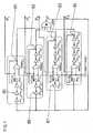
- ⁇ max of the generated random bitsone can combine several ring oscillators with different periods (ie with different values for K).
- the two circuits according to Figures 19a and 19bdiffer only in the procurement of the start / stop inputs of the ring oscillators 17, 18, 19, 20, 21, 22.
- the start / stop Inputs of the individual ring oscillators 17, 18, 19jointly controlled.
- the second option shown in FIG. 19bis to separately control the inputs in order to shift the initial phases of the individual oscillation signals relative to each other.
- Fig. 20aa circuit with parity check of two ring oscillators 24, 25 with common start / stop signal is shown.
- the period P of the parity signal PS, 29remains constant.
- the signal curve 29 of the parity signal PS, within a period Pchanges over larger time intervals, which is clearly visible in Fig. 21a.
- the envelope 30 of the parity signal PS, 29 over a period of about 0.2 s in FIG. 21 bshows a more variable autocorrelation, which is smaller than the autocorrelation of the individual components (see FIG. 18).
- This parity check of ring oscillatorsis used in many realizations of random number generators. With this technique, you can not completely remove the correlations, and therefore additional, rate-decreasing, deterministic post-processing becomes inevitable.
- the object of the inventionis now to execute such a random number generator of the generic type and a method for generating a random number sequence, as is known from the prior art, such that a deterministic post-processing is no longer necessary.
- the inventionis based on a method for generating random numbers, in which at least two ring oscillators oscillating digital output signals of equal or different periodicity are generated and in which a logical state, namely logic "0" or "1", representing external parity signal is generated, which takes the logical state "1” if and only if an odd number of output signals has the logical state "1", and otherwise assumes the logic state "0".
- the external parity signalis fed back in each case to an external parity input of the respective ring oscillators.
- the external parity signalcan be used to generate random bits by sampling it.
- the autocorrelation of the parity signalis significantly reduced over the prior art methods without feedback. Therefore, with the method according to the invention, the rate of the generated random bits can be increased significantly.
- a random number generatorsimilarly comprises at least two ring oscillators constructed preferably of independent free-running feedback inverters with an odd number of inverters connected in series, which generate the aforementioned oscillating digital output signals of equal or different periodicity, and first, preferably by an exclusive-OR Gate formed, parity signal generating means which generate the aforementioned external parity signal.
- an exclusive-OR Gateformed, parity signal generating means which generate the aforementioned external parity signal.
- feedback coefficients formed by exclusive-OR gatesare provided which couple this external parity signal back to the respective one external parity input of the respective ring oscillators (formed from inverter chains).
- an internal parity signal representing a given logical state(eg "1") is generated for each ring oscillator when either the output signal of the respective ring oscillator or the signal fed back to the external parity input of the respective ring oscillator has a predetermined value logical state (eg "1") occupies.
- These internal parity signalscan be converted into another parity signal by further parity signal generation of the type described above, which can be used to generate random bits in the manner described above by sampling it. This further parity formation results in a signal whose autocorrelation is again significantly reduced compared to the external parity signal. Along with this, the possible sampling rate for generating the random bits can be significantly increased once again in this way.
- the random number generator according to the inventionaccordingly comprises corresponding parity signal generating means for generating the inner parity signals.
- Thesepreferably include exclusive-OR gates, each having an external parity input and an output signal input.
- a signal derived from the external parity signalfor example the parity signal itself or a signal whose generation is described in detail below, is present at the external parity input.
- At the output signal inputis the respective output signal of the respective ring oscillator.
- the random number generator according to the inventioncomprises further parity signal generating means which generate the further parity signal representing a logic state "0" or "1” if an odd number of the internal parity signals assumes a predetermined logical state (eg "1").
- These meansalso preferably comprise in an appropriate manner an exclusive-OR gate (XOR gate) at the inputs of which the internal parity signals are present.
- XOR gateexclusive-OR gate
- starting meanswhich generate a start signal (e.g., a logic "1") and supply at least one of the ring oscillators to a start / stop input so as to excite it for oscillation.
- a start signale.g., a logic "1
- thishas a NAND gate with two inputs instead of an input-side inverter. The one input and the output of this NAND gate are connected in place of the input and the output of the removed inverter with the remaining inverter chain. The other input forms the aforementioned start / stop input for supplying the start signal.
- all ring oscillatorscan be started separately via corresponding start / stop inputs.
- start signale.g., logic "1”
- all of the ring oscillatorsare each provided with a NAND gate instead of an input side inverter, whose start / stop inputs for supplying the start signal (e.g., logic "1") are connected to each other.
- This startup problemcan be eliminated by in that at least one external parity input is preceded by an inverter, to which the external parity signal is supplied.
- this invertercauses a delay of the signal at this external parity input and, on the other hand, a polarity reversal of the signal occurs at this external parity input with an upstream inverter.
- the latterleads to a polarity reversal at the input of the corresponding ring oscillator and thus to an initiation of the oscillation in this ring oscillator.
- the other connected ring oscillatorsare excited to vibrate.
- both the external parity signal and the further parity signalcan be used to generate random bits.
- the random number generator according to the inventionmay therefore comprise sampling means sampling the external parity signal to generate random bits at a predetermined rate and / or sampling means sampling the further parity signal to produce random bits at a predetermined rate.
- the maximum sampling ratecan be further increased if several random number generators of the type described above are combined. Starting from random number generators, which generate external, in particular sampled, parity signals and / or which generate further, in particular sampled, parity signals by repeated or repeated parity formation from these parity signals (any variations of parity signal formations are possible). Random number generators form random number generators provided (super) parity signal has an almost arbitrarily reduced autocorrelation.
- the further random number generationrequires a scan. It does not matter whether the external parity signals or the other parity signals or other low-order parity signals for generating random bits are sampled synchronously at a predetermined rate or the highest order (super) parity signal is sampled at the predetermined rate to generate random bits.
- the samplingcan be done at constant time intervals, but according to the invention it is also intended to perform a sampling in random, non-uniform sampling intervals.
- a random scancan be achieved when the sampling is performed at a time when a random bit randomly generated by one of the random generators described above assumes a predetermined logical state (eg, "1").
- the samplingcan be carried out, for example, by means of a D-flip-flop, which is driven in one cycle by a clock, in particular by an astable multivibrator (at temporally constant sampling intervals) or by a feedback ring oscillator of the type described above (at temporally random sampling intervals) ,
- the basic idea of the inventionis, as stated above, in the feedback of the parity signal to the inputs of the individual ring oscillators.
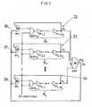
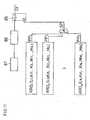
- Fig. 1shows a first embodiment of a random generator according to the invention based on a number L of ring oscillators 32, 33, 34, the outputs of which are supplied to corresponding inputs of an XOR gate xor at which a parity signal PS is formed.
- the supply of the feedback parity signal PS to the individual inputs of the ring oscillators 32, 33, 34is achieved by a number of logical XOR gates xor 1 , xor 2 ,... Xor L.
- the respective input to which the parity signal PS is appliedshould be referred to as external parity input 36, 37, 38.
- Fig. 2athe logic state of the switched-off circuit is shown.
- Fig. 2bshows the state of the circuit after switching on (ie after setting the start / stop signal to logic "1").
- This startup problemcan be remedied by inserting another inverter inv 3, -1 in front of the external parity input 47 of the XOR gate (see FIG. 3).
- the parity signal PS of this now oscillating circuitis shown in FIG. 4 for different time intervals. It can be clearly seen that the feedback for a suitable (oscillating) parameter combination leads to a very irregular form of the parity signal PS.
- the averaged parity signal PSshows a very low and constant autocorrelation (see FIG. 5). Compared to Fig. 21b, this is a significant improvement that allows to significantly increase the rate ⁇ of the generated random bits.
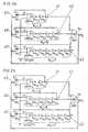
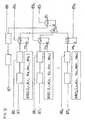
- Fig. 6shows a general circuit diagram with feedback parity signal PS.
- This circuitwill be referred to below as feedback ring oscillators RRO.
- the parity signal PS at the output of the XOR gate XORshould be referred to as an external parity signal.
- RRO4, 1,3,4,5, 3,2,1,0
- the inner parity signalsare very different by the construction of the RRO, as shown in FIG. 8, and can be used to generate random bits.
- a further parity check PP of the inner parity signals P 1 , P 2 ,... P Lat which a further parity signal PP is generated, the quality is further improved and can be used after sampling as a random bit sequence ZB, as shown in FIG is shown.
- the samplingis carried out by a D flip-flop 85, which is driven by a periodic clock signal C p .
- the clock signal C pcan be generated by an astable multivibrator 87 and its period (uniform sampling interval) can be determined by a binary counter 86.
- the astable multivibrator 87may be replaced by an RRO.
- Fig. 10shows a random number generator with the RRO instance RRO (4; 1,3,4,5; 3,2,1,0) with uniform sampling. Statistical tests of this random number generator have shown a low bias and a small correlation of bits 7.
Landscapes
- Engineering & Computer Science (AREA)
- Physics & Mathematics (AREA)
- Theoretical Computer Science (AREA)
- General Physics & Mathematics (AREA)
- General Engineering & Computer Science (AREA)
- Computer Security & Cryptography (AREA)
- Signal Processing (AREA)
- Mathematical Analysis (AREA)
- Mathematical Optimization (AREA)
- Pure & Applied Mathematics (AREA)
- Computer Networks & Wireless Communication (AREA)
- Computational Mathematics (AREA)
- Detection And Correction Of Errors (AREA)
- Error Detection And Correction (AREA)
- Logic Circuits (AREA)
- Permanent Magnet Type Synchronous Machine (AREA)
- Stereo-Broadcasting Methods (AREA)
- Indexing, Searching, Synchronizing, And The Amount Of Synchronization Travel Of Record Carriers (AREA)
- Signal Processing For Digital Recording And Reproducing (AREA)
- Manipulation Of Pulses (AREA)
Abstract
Description
Translated fromGermanDie Erfindung betrifft einen Zufallsgenerator gemäß dem Oberbegriff des Patentanspruchs 15 sowie ein Verfahren zur Erzeugung von Zufallszahlen nach dem Oberbegriff des Patentanspruchs 1.The invention relates to a random number generator according to the preamble of
Zufallszahlengeneratoren (engl. Random Number Generators - RNGs) dienen der automatischen Erzeugung von zufälligen binären oder mehrwertigen Zahlen (Zufallszahlen). Zufallszahlengeneratoren werden in einer Vielzahl von Anwendungsbereichen benötigt. Hierzu gehören zum Beispiel:
- Kryptografische Anwendungen,
- Stochastische Simulationen,
- Testen von Software und Hardware,
- Computerspiele.
- Cryptographic applications,
- Stochastic simulations,
- Testing software and hardware,
- Computer games.
Im Folgenden werden ausschließlich kryptografische Anwendungen von Zufallszahlengeneratoren betrachtet. Zu diesen Anwendungen gehören beispielsweise:
- Für Authentifikation:
- Challenge-Response-Protokolle,
- Zero-Knowledge-Beweise.
- Für Schlüsselaustausch-Protokolle:
- Diffie-Hellmann-Verfahren,
- Zur Schlüsselerzeugung,
- Sitzungsschlüssel für symmetrische Verschlüsselungsverfahren,
- Schlüsselerzeugung für asymmetrische Verschlüsselungsverfahren (Public-Key-Verfahren),
- Erzeugung von binärem Rauschen (Ontetime-Pad, Mc-Eleice Public-Key-Verfahren),
- Parametererzeugung für Public-Key-Verfahren (z. B. die Erzeugung zufälliger Primzahlen).
- Für andere kryptografische Anwendungen:
- Passworterzeugung,
- Initialwerte (engl. Seeds) für deterministische Zufallszahlengeneratoren (Pseudo-Zufallszahlengeneratoren),
- Ergänzung von Klartext-Blöcken (engl. Padding),
- Sicheres Löschen von Speichermedien (durch mehrfaches Überschreiben mit zufälligen Bitmustern).
- For authentication:
- Challenge-response protocols,
- Zero-knowledge proofs.
- For key exchange protocols:
- Diffie-Hellman method,
- For key generation,
- Session key for symmetric encryption methods,
- Key generation for asymmetric encryption methods (public-key method),
- Generation of binary noise (on-time pad, Mc-Elece public-key method),
- Parameter generation for public-key methods (eg the generation of random primes).
- For other cryptographic applications:
- Password generation,
- Seeds for deterministic random number generators (pseudo-random number generators),
- Addition of plaintext blocks (English padding),
- Secure erase of storage media (by multiple overwriting with random bit patterns).
Im Allgemeinen werden zwei Hauptarten von Generatoren unterschieden, die deterministischen (engl. Pseudo Random Number Generator - PRNG) und die physikalischen Zufallszahlengeneratoren (engl. True Random Number Generator - TRNG). Bei deterministischen Generatoren handelt es sich um algorithmische Verfahren, welche aus einem zufällig gewählten Initialwert (engl. Initial Value - IV) eine viel längere Folge von Zahlen erzeugen, die zufällig erscheint. Natürlich kann diese Folge, durch den deterministischen Charakter der Erzeugungsmethode, per se nicht echt zufällig sein.In general, two main types of generators are distinguished, the deterministic (pseudo random number generator - PRNG) and the physical random number generator (true random number generator - TRNG). Deterministic generators are algorithmic methods that produce a much longer sequence of numbers from a randomly chosen initial value (IV) that appears random. Of course, due to the deterministic nature of the generation method, this sequence may not be truly random per se.
Um tatsächlich zufällige Folgen von Zahlen erzeugen zu können, muss daher ein so genannter physikalischer Zufallszahlengenerator verwendet werden. Dieser nutzt zur Erzeugung der Zufallszahlen entweder nichtdeterministische oder chaotische physikalische Prozesse. Durch Messung und Bearbeitung von bestimmten Prozessmessgrößen (z. B. Spannung des thermischen Rauschens an einem Widerstand), werden dann die Zufallszahlen erzeugt.In order to actually generate random sequences of numbers, therefore, a so-called physical random number generator must be used. This uses either non-deterministic or chaotic to generate the random numbers physical processes. By measuring and processing certain process measurements (eg, thermal noise voltage across a resistor), the random numbers are then generated.
Ziel dieser Erfindung ist, einen physikalischen Zufallszahlengenerator zu realisieren, welcher in integrierten Schaltkreisen (Integrated Circuits = ICs) eingesetzt (eingebettet) werden kann und die folgenden kryptografischen und wirtschaftlich relevanten Gütekriterien erfüllt:
- Implementierbar ausschließlich unter Verwendung standardisierter Bauelemente der herkömmlichen hochintegrierten Schaltkreise (z. B. logische Gatter),
- Aufgebaut unter Nutzung möglichst weniger Bauelemente (kostengünstig, mit kleiner Oberfläche und geringem Stromverbrauch),
- Eingebettet als eigenständige, unabhängige, vor dem Einfluss anderer Einheiten geschützte Einheit auf dem IC
- Ein- und Ausschalten unabhängig von den übrigen Einheiten auf dem IC
- Schnelles Wiederherstellen der Funktionalität nach dem Einschalten (kurze Einwärme-Zeit)
- Möglichst hohe Anzahl von erzeugten Zufallbits pro Zeit (hohe Rate)
- Robustheit gegenüber Umgebungsbedingungen (Temperatur, elektromagnetische Störungen, Änderungen der Speisespannung, etc.)
- Robustheit gegenüber invasiven und nichtinvasiven Manipulationsversuchen (Angriffen)
- Passive Angriffe
- Aktive Angriffe
- Erfüllung statistischer Tests, welche die Qualität des Zufalls beider erzeugten Bits beurteilen
- Möglichst wenig deterministische Nachbearbeitung der erzeugten Zufallszahlen
- Möglichkeit einer Funktionalitäts- und Qualitätsprüfung während des Betriebs (Online-Test).
- Implementable exclusively using standardized components of conventional large scale integrated circuits (eg logic gates),
- Built using as few components as possible (cost-effective, with a small surface and low power consumption),
- Embedded as a stand-alone, independent unit protected from the influence of other units on the IC
- Switch on and off independently of the other units on the IC
- Quick recovery of functionality after switching on (short warm-up time)
- As high as possible number of generated random bits per time (high rate)
- Robustness to environmental conditions (temperature, electromagnetic interference, changes in the supply voltage, etc.)
- Robustness to invasive and non-invasive manipulation attempts (attacks)
- Passive attacks
- Active attacks
- Fulfill statistical tests that assess the quality of the randomness of both generated bits
- As little as possible deterministic post-processing of the generated random numbers
- Possibility of a functionality and quality check during operation (online test).
Im Folgenden wird davon ausgegangen, dass ein kryptografischer Zufallszahlengenerator als Bitquelle realisiert ist. Je nach Anwendung werden die einzelnen Bits zu Blöcken zusammengefasst (z. B. 56 Bits für einen Schlüssel des Data Encryption Standard - DES). Im Allgemeinen ist davon auszugehen, dass die durch einen kryptografischen Zufallszahlengenerator erzeugten Bitfolgen (z. B. ein Schlüssel) geheim bleiben müssen, um die Sicherheit des Kryptosystems nicht zu kompromittieren (in den im vorigen Abschnitt aufgeführten Anwendungen gilt dies für alle Verfahren, bis auf Challenge-Response-Protokolle und Zero-Knowledge-Beweise). In diesen Fällen erzeugt der Zufallszahlengenerator das Geheimnis (engl. Secret) des jeweiligen Kryptoverfahrens. Mithilfe dieses Geheimnisses werden nun z. B. Klartexte chiffriert. Falls dem Angreifer das Geheimnis unbekannt ist, hat er immer die Wahl alle möglichen Bitfolgen durchzuprobieren (vollständige Suche). Im obigen Beispiel würde dies bedeuten, dass der Angreifer, welcher ein mit dem unbekannten Schlüssel chiffrierten Klartext beobachtet hat, im (statistischen) Mittel 255 mögliche Schlüssel durchprobieren muss, bis er erwarten kann, den tatsächlich erzeugten Schlüssel gefunden zu haben. Dieser Angriff ist aus Sicht des Angreifers der schlechtest mögliche Fall. Um ein System erfolgreich anzugreifen, muss der Angreifer in der Lage sein, eine Vorhersage über eine bestimmte Anzahl von Bits zu treffen, die ein Generator zu einem bestimmten Zeitpunkt erzeugt. Dies kann ohne Kenntnis anderer vom Generator erzeugten Bitfolgen geschehen oder unter Kenntnis von Bitfolgen, die der Generator vor oder nach der unbekannten Bitfolge erzeugt hat. Der Angreifer kann entweder versuchen die erzeugte Bitfolge komplett oder nur zu Teilen zu erraten. Im letzteren Fall kann er die verbleibenden Bits durch eine vollständige Suche finden.In the following it is assumed that a cryptographic random number generator is realized as a bit source. Depending on the application, the individual bits are combined into blocks (eg 56 bits for a key of the Data Encryption Standard - DES). In general, it can be assumed that the bit sequences generated by a cryptographic random number generator (eg a key) must remain secret in order not to compromise the security of the cryptosystem (in the applications listed in the previous section, this applies to all methods, except for Challenge-response protocols and zero-knowledge evidence). In these cases, the random number generator generates the secret of the respective crypto method. Now, with the help of this mystery z. For example, clear texts are encrypted. If the attacker is unaware of the secret, he always has the option to try all possible bit sequences (full search). In the above example, this would mean that the attacker, who has been watching a plaintext encrypted with the unknown key, has to try 255 possible keys on the (statistical) means until he can expect to have found the actual generated key. This attack is the worst case from the attacker's point of view. To successfully attack a system, the attacker must be able to make a prediction about a certain number of bits that a generator generates at a particular time. This may be done without knowledge of other bit sequences generated by the generator, or knowing bit sequences generated by the generator before or after the unknown bit sequence. The attacker can either try to guess the generated bit sequence completely or only partially. In the latter case, he can find the remaining bits through a full search.
Um eine solche Vorhersage zu treffen, stehen dem Angreifer alle bekannten technischen und wissenschaftlichen Mittel zur Verfügung. Er ist nur hinsichtlich der für den Angriff aufzuwendenden Kosten eingeschränkt. Man kann davon ausgehen, dass diese unter einer festgelegen Kostengrenze zu liegen haben (ein ökonomisches Argument: Der zu erwartende Gewinn durch den Angriff sollte die Kosten für den Angriff nicht überschreiten).In order to make such a prediction, the attacker has all the known technical and scientific means at his disposal. It is limited only in terms of the costs to be spent on the attack. It can be assumed that these are below a fixed cost limit (an economic argument: the expected gain from the attack should not exceed the cost of the attack).
Je nach Höhe der Kostengrenze kann die Bitquelle in verschiedene Sicherheitsstufen eingeteilt werden. Widersteht eine Bitquelle für eine gegebene Kostengrenze allen Angriffen, so soll sie, bezüglich dieser Kostengrenze, als praktisch sichere Bitquelle bezeichnet werden.Depending on the amount of the cost limit, the bit source can be divided into different security levels. Withstand a bit source for a given cost limit all attacks, it should be referred to as a practically secure bit source with respect to this cost limit.
Die Figur 14 zeigt ein Modell eines physikalischen Zufallszahlengenerators TRNG in Form einer physikalischen Bitquelle. Wesentlicher Bestandteil der Quelle ist ein physikalisches dynamisches, unvorhersagbares System, die so genannte Zufallsquelle 1. Mit dieser Zufallsquelle 1 kann ein interner (zeitabhängiger) Zustand assoziiert werden. In zeitlichen Abständen wird der Wert des Zustands der Zufallsquelle 1 gemessen und bearbeitet (Werteermittlung 2) und hieraus ein oder mehrere Zufalls-Bit erzeugt (Zufalls-Bit-Erzeugung 3). Folgen dieser derart erzeugten Zufallsbits werden als interne Zufallsbits bezeichnet. Diese können anschließend einer algorithmischen Nachbearbeitung 5 unterzogen werden. Die mathematische Nachbearbeitung 5 dient im Allgemeinen dem Zweck, die Qualität der internen Zufallszahlen zu verbessern (ein Maß für die Qualität von Zufallszahlen muss hierbei noch definiert werden. Näheres hierzu im folgenden Abschnitt). Im Allgemeinen spricht man von Zufallsextraktion 5. Hierunter ist die Beseitigung von Abhängigkeiten zwischen aufeinander folgenden erzeugten Bits und der Beseitigung eines oftmals vorhandenen Bias (Ungleichverteilung der Nullen und Einsen) zu verstehen. Die hierbei erzeugten Zufallsbits werden in einem weiteren Schritt ausgegeben und gegebenenfalls in einem Ausgabespeicher hinterlegt (Zufalls-Bit-Ausgabe 5).FIG. 14 shows a model of a physical random number generator TRNG in the form of a physical bit source. An essential component of the source is a physical dynamic, unpredictable system, the so-called
Wie in Figur 14 dargestellt, ist ein physikalischer Zufallszahlengenerator TRNG kein isoliertes System, sondern eingebettet in eine physikalische Umgebung 6. Es ist davon auszugehen, dass der gemessene Zustand und damit auch die erzeugten Zufallsbits von bestimmten physikalischen Größen der Umgebung 6 abhängig sind. Hierzu gehören Größen, wie z. B. die an das Gerät gelieferte Versorgungsspannung, die Umgebungstemperatur oder elektromagnetische Felder.As shown in FIG. 14, a physical random number generator TRNG is not an isolated system but is embedded in a
Anhand der Art des physikalischen Systems können verschiedene Arten von Generatoren unterschieden werden. Es können zwei wesentliche Arten der verwendeten physikalischen Systeme ausgemacht werden:
- Quantenphysikalische Systeme,
- Klassisch physikalische Systeme.
- Quantum physical systems,
- Classically physical systems.
Unter einem quantenphysikalischen System versteht man ein System, welches durch die Gesetze der Quantenmechanik beschrieben wird. Nach der derzeitigen allgemeinen wissenschaftlichen Ansicht sind die hierbei auftretenden Phänomene, auf welche sich dann die Zufallserzeugung abstützt, echt zufällig. Beispiele hierfür sind Zerfallsprozesse von radioaktiven Materialien.A quantum physical system is a system that is described by the laws of quantum mechanics. According to the current general scientific view, the phenomena that occur on which random production is based are truly random. Examples include decay processes of radioactive materials.
Klassisch physikalische Systeme hingegen werden durch die deterministischen Gesetze der (klassischen) Physik beschrieben. Dass diese Systeme trotzdem unvorhersagbar sein können, kann verschiedene Gründe haben. Für Systeme mit vielen Freiheitsgraden sind die auftretenden Wechselwirkungen innerhalb des Systems oft zu komplex um sie exakt vorherzusagen. Hinzu kommt, dass der Anfangszustand des Systems oft nicht exakt bestimmt werden kann. Dieser Umstand hat im Falle so genannter chaotischer Systeme weitere Auswirkungen. In solchen Systemen führen kleinste Änderungen im Anfangszustand, im Laufe der Zeit, zu sich stark unterscheidenden, nicht vorhersagbaren Systemzuständen.By contrast, classical physical systems are described by the deterministic laws of (classical) physics. That these systems can still be unpredictable can have different causes. For systems with many degrees of freedom, the interactions that occur within the system are often too complex to accurately predict. In addition, the initial state of the system often can not be determined exactly. This circumstance has further effects in the case of so-called chaotic systems. In such systems, minute changes in the initial state, over time, lead to highly discriminating, unpredictable system states.
Um eine kryptografische Bitquelle zu beurteilen, muss sie mit den Eigenschaften der vorstehend vorgestellten praktisch sicheren kryptografischen Bitquelle verglichen werden. Hierzu gehören eine statistische Beurteilung der erzeugten Bitfolgen und eine Prüfung der Möglichkeiten der so genannten Seitenkanalangriffe. Beim Einsatz von Zufallszahlengeneratoren in eingebetteten Systemen kommt diesen Angriffen tatsächlich eine große Bedeutung zu. Unter einem Seitenkanalangriff ist ein Versuch zu verstehen, die vom Generator erzeugten Zahlen vorherzusagen, bzw. ihre Erzeugung zu beeinflussen. Dies geschieht nicht-invasiv durch Ermittlung von Messwerten aus der Umgebung des Generators (passive Angriffe), bzw. durch eine gezielte Beeinflussung der Umgebung (aktive Angriffe). Eine weitere Verschärfung eines solchen Angriffs stellen die invasiven Seitenkanalangriffe dar (zum Beispiel könnte der IC aufgebohrt werden, um dort Signale zu messen). Typische passive, nicht-invasive Angriffe sind zum Beispiel die Messung der elektromagnetischen Abstrahlung oder des Stromverbrauchs des Generators.To judge a cryptographic bit source, it must be compared to the characteristics of the practically secure cryptographic bit source presented above. These include a statistical assessment of the generated bit sequences and a review of the possibilities of the so-called side channel attacks. When using random number generators in embedded systems, these attacks are in fact of great importance. A side channel attack is an attempt to predict the numbers generated by the generator, or to influence their generation. This is done non-invasively by determining measured values from the environment of the generator (passive attacks) or by deliberately influencing the environment (active attacks). A further aggravation of such an attack is the invasive side channel attacks (for example, the IC could be drilled out to measure signals). Typical passive, non-invasive attacks are, for example, the measurement of the electromagnetic radiation or the power consumption of the generator.
Für die statistische Beurteilung der, durch einen Generator generierten Bitfolgen stehen verschiedene statistische Tests zur Verfügung (z. B.
Prinzipiell steht man bei der Beurteilung dieser endlichen Bitfolgen vor dem Problem der Definition des Begriffs einer zufälligen endlichen Sequenz. Nach Kolmogorov (
Die statistischen Tests sind nur in der Lage eine Bitfolge bezüglich bestimmter Eigenschaften zu prüfen, welche man zufälligen (endlichen) Bitfolgen zuweist. Diese Eigenschaften leiten sich oft aus intuitiven Vorstellungen ab, welche man nach allgemeiner Auffassung vom Zufall hat. Tatsächlich konnte von einer Reihe Tests gezeigt werden, dass sie, von im Sinne Kolmogorov zufälligen Bitfolgen, bestanden werden (
Aus dem Stand der Technik sind nunmehr physikalische Zufallszahlengeneratoren in einer Vielzahl von Abwandlungen bekannt. Zu Beginn der Zufallszahlengeneratorenentwicklung wurden vorwiegend externe, d. h. nicht in ICs eingebettete Zufallszahlengeneratoren entwickelt. Hierfür steht eine größere Auswahl an verwendeten Zufallsquellen zur Verfügung. In heutigen, externen Zufallszahlengeneratoren werden eine Vielzahl von Zufallsquellen verwendet, beispielsweise radioaktive Quellen, elektronisches, thermisches Rauschen in Widerständen oder zufällige Ereignisse in der Umgebung (z. B. Zeitintervalle zwischen Tastendrucken auf einer Tastatur).Now, physical random number generators in a variety of modifications are known in the art. At the beginning of the random number generator development, mainly external, i. H. non-IC embedded random number generators. There is a wider choice of random sources used. Today's external random number generators use a variety of random sources, such as radioactive sources, electronic, thermal noise in resistors, or random events in the environment (e.g., time intervals between keystrokes on a keyboard).
Erst in jüngster Zeit werden in kommerziellen ICs Zufallszahlengeneratoren eingebettet. Hier spielen nun die Art der Zufallsquelle, deren Oberflächengröße auf dem IC, die technische Realisierung und Miniaturisierung eine wichtige Rolle. Allerdings wird bis heute die Immunität der Zufallszahlengeneratoren gegen Seitenkanalangriffe kaum beachtet. Beispiele für realisierte eingebettete Zufallszahlengeneratoren finden sich in
Die Erfindung geht von einem sogenannten Inverterketten-Zufallszahlengenerator aus, wie er gemäß dem Stand der Technik in unterschiedlichster Ausführung beschrieben ist. Beispielhaft wird auf die
Grundbaustein dieser Zufallszahlengeneratoren ist ein so genannter Ringoszillator 8. Er besteht aus der seriellen Verbindung von einer ungeraden Anzahl K von Invertern inv1, inv2, ...invK (logischen NOT-Gattern), wobei der Ausgang des letzten Inverters invK mit dem Eingang des ersten Inverters inv1 verbunden ist (siehe Fig. 15a). Durch die Verzögerungszeiten der einzelnen Inverter inv1, inv2, .. invK kommt es nur bei einer ungeraden Anzahl K von Gattern inv1, inv2, ...invK zu einer periodischen Schwingung.The basic building block of these random number generators is a so-called ring oscillator 8. It consists of the serial connection of an odd number K of inverters inv1 , inv2 , ... invK (logical NOT gates), wherein the output of the last inverter invK with is connected to the input of the first inverter inv1 (see Fig. 15a). Due to the delay times of the individual inverters inv1 , inv2 ,... InvK , only an odd number K of gates inv1 , inv2 ,... InvK results in a periodic oscillation.
Um diese Schwingung zu starten bzw. zu stoppen, kann der erste Inverter inv1 durch ein NAND-Gatter nand1 mit Steuereingang start/stop ersetzt werden (siehe Fig. 15b). Wird dieser Steuereingang start/stop auf logisch Eins ("1") gesetzt, beginnt der Ringoszillator 9 zu schwingen.To start or stop this oscillation, the first inverter inv1 can be replaced by a NAND gate nand1 with control input start / stop (see FIG. 15 b). If this control input start / stop is set to logic one ("1"), the
Fig. 16a zeigt einen Ringoszillator 10 für K=3 mit zwei Invertern inv2, inv3 und einem NAND-Gatter nand1. Fig. 16b zeigt einen idealisierten Signalverlauf am Eingang 11 und Ausgang 12 eines Inverters inv, dessen Verzögerungszeit τ beträgt. Nimmt man an, das die Gatter nand1, inv2, inv3 im Ringoszillator 10 nach Fig. 16a ein derartig idealisiertes Verhalten aufweisen, so zeigt Fig. 16c den idealisierten Signalverlauf des Ringoszillators 10 gemäß der Figur 16a an den Punkten S, B, C und A=A', nachdem der Eingang S für eine Laufzeit T auf "1" gesetzt wurde.FIG. 16 a shows a
Für eine technische Realisierung des Ringoszillators 10 mit K=3 mit dem CMOS-Baustein 74HCT04 (ohne Eingangs-NAND-Gatter, Fig. 17a), ist ein mit einem Oszilloskop aufgenommener Signalverlauf 14 am Punkt A' in Fig. 17b darstellt. Wie sich aus der Ausschnittsvergrößerung des Signalverlaufs 14 (in Fig. 17b) ergibt, wird durch thermische Bewegung der Elektronen in den Leitungen des Schaltkreises 74HCT04 ein thermisches Rauschsignal aufaddiert. Fig. 17c zeigt die Hüllkurve 15 des verrauschten Schwingungssignals 14 beobachtet über ein längeres Zeitintervall t. Wie zu bemerken ist, führt das Rauschen in den Flanken des Signals 14 zu einer früheren oder späteren Überschreitung des Entscheidungspegels relativ zum rauschfreien Signal. Diese zeitlich zufällige Verschiebung der Flanken wird als Jitter bezeichnet. Die Differenz zwischen den maximal möglichen Flankenverschiebungen, beobachtet bezüglich eines fixen Zeitpunktes t1 (Fig. 17c), ist mit dem Bezugszeichen Δ bezeichnet. Der Betrag dieser Differenz Δ nimmt zu, je weiter die Flanke von dem Bezugszeitpunkt t1 entfernt ist. Dieses Phänomen ist als Jitter-Akkumulation bekannt.For a technical realization of the
In Fig. 18 ist ein Schwingungssignal 14 des Ringoszillators 10 aus Fig. 17a, mit einer Frequenz f von ca. 25 MHz, 512 mal über die Dauer von 0,2 s gemittelt, dargestellt. Die Einhüllende 13 dieses gemittelten Signals zeigt den Verlauf der Autokorrelation für verschiedene zeitliche Abstände vom Triggerpunkt an. Wie man aus Fig. 18 sehen kann, wird das Signal 14 erst nach ca. 0,28 s durch akkumulierten Jitter vollständig dekorreliert.
Dies bedeutet, dass die erzeugten Bits erst bei einer Abtastungsrate ν von 3 Hz (oder kleiner) dekorreliert wären und somit für eine Zufallsbitquelle genutzt werden könnten. Um die maximal mögliche Rate νmax der erzeugten Zufallsbits zu erhöhen, kann man mehrere Ringoszillatoren mit verschiedenen Perioden (d.h. mit verschiedenen Werten für K) kombinieren. Figur 19 zeigt zwei Ausführungsbeispiele für Schaltungsanordnungen basierend auf einer Anzahl L von Ringoszillatoren 17, 18, 19, 20, 21, 22. Hierbei wird jeweils eine Paritätsprüfung (sogenanntes XORing) der Ausgänge durchgeführt. Konkret bedeutet dies, dass die Ausgänge der jeweiligen Ringoszilatoren 17, 18, 19, 20, 21, 22 mit den Eingängen eines XOR-Gatters xor verbunden werden, so dass an dessen Ausgang genau dann ein "1"-Signal erzeugt wird, wenn an den Ausgängen der Ringoszilatoren 17, 18, 19, 20, 21, 22 eine ungerade Anzahl von logischen "1" anliegt. Eine gerade Anzahl von logischen "1" wird am Ausgang des XOR-Gatters xor ein "0"-Signal erzeugen. Deshalb wird das Signal am Ausgang des XOR-Gatters xor nachfolgend als Paritätssignal PS bezeichnet.In Fig. 18, a
This means that the generated bits would be decorrelated only at a sampling rate ν of 3 Hz (or less) and thus could be used for a random bit source. In order to increase the maximum possible rate νmax of the generated random bits, one can combine several ring oscillators with different periods (ie with different values for K). FIG. 19 shows two exemplary embodiments of circuit arrangements based on a number L of
Die beiden Schaltungen gemäß den Figuren 19a bzw. 19b unterscheiden sich lediglich in der Beschaffung der start/stop-Eingänge der Ringoszillatoren 17, 18, 19, 20, 21, 22. Bei der ersten Ausführungsvariante gemäß der Fig. 19a werden die start/stop-Eingänge der einzelnen Ringoszillatoren 17, 18, 19 gemeinsam angesteuert. Die zweite in Fig. 19b dargestellte Möglichkeit besteht darin, die Eingänge separat anzusteuern, um damit die Anfangsphasen der einzelnen Schwingungssignale gegeneinander zu verschieben.The two circuits according to Figures 19a and 19b differ only in the procurement of the start / stop inputs of the
In Fig. 20a ist eine Schaltung mit Paritätsprüfung von zwei Ringoszillatoren 24, 25 mit gemeinsamem start/stop Signal dargestellt. Wie in Fig. 20b und 20c zu sehen ist, bleibt die Periode P des Paritätssignals PS, 29 konstant. Durch langsame Phasenverschiebungen der einzelnen Ringoszillator-Signale 27, 28 ändert sich der Signalverlauf 29 des Paritätssignals PS, innerhalb einer Periode P über größere Zeitabstände, was in Fig. 21a deutlich zu sehen ist. Die Einhüllende 30 des Paritätssignals PS, 29 über einen Zeitraum von ca. 0,2.s in Fig. 21b zeigt eine variablere Autokorrelation, die kleiner ist, als die Autokorrelation der einzelnen Komponenten (siehe Fig. 18). Diese Paritätsprüfung von Ringoszillatoren wird in vielen Realisierungen von Zufallszahlengeneratoren benutzt. Mit dieser Technik kann man die Korrelationen nicht komplett entfernen und daher wird eine zusätzliche, die Rate herabsetzende, deterministische Nachbearbeitung unvermeidbar.In Fig. 20a a circuit with parity check of two
Die Aufgabe der Erfindung besteht nunmehr darin, einen Zufallszahlengenerator der gattungsgemäßen Art sowie ein Verfahren zur Erzeugung einer Zufallszahlenfolge, wie es aus dem Stand der Technik bekannt ist, derart auszuführen bzw. weiterzubilden, dass eine deterministische Nachbearbeitung nicht mehr notwendig ist.The object of the invention is now to execute such a random number generator of the generic type and a method for generating a random number sequence, as is known from the prior art, such that a deterministic post-processing is no longer necessary.
Diese Aufgabe wird durch einen Zufallszahlengenerator mit den Merkmalen des Patentanspruchs 15 sowie durch ein Verfahren mit den Merkmalen des Patentanspruchs 1 gelöst.This object is achieved by a random number generator having the features of
Vorteilhafte Ausführungen und Weiterbildungen der Erfindung sind in den Unteransprüchen angegeben.Advantageous embodiments and further developments of the invention are specified in the subclaims.
Die Erfindung geht von einem Verfahren zur Erzeugung von Zufallszahlen aus, bei dem von wenigstens zwei Ringoszillatoren oszillierende digitale Ausgangssignale gleicher oder unterschiedlicher Periodizität erzeugt werden und bei dem ein einen logischen Zustand, nämlich logisch "0" oder "1", darstellendes externes Paritätssignal erzeugt wird, welches genau dann den logischen Zustand "1" einnimmt, wenn eine ungerade Anzahl der Äusgangssignale den logischen Zustand "1" hat, und ansonsten den logischen Zustand "0" einnimmt. Erfindungsgemäß ist vorgesehen, dass das externe Paritätssignal auf jeweils einen externen Paritätseingang der jeweiligen Ringoszillatoren rückgekoppelt wird. Wie aus dem Stand der Technik bekannt ist kann das externe Paritätssignal zur Erzeugung von Zufallsbits verwendet werden, indem es abgetastet wird. Aufgrund der Rückkopplung des Paritätssignals auf den (externen Paritäts-) Eingang des jeweiligen Ringoszillators wird die Autokorrelation des Paritätssignals gegenüber dem aus dem Stand der Technik bekannten Verfahren ohne Rückkopplung signifikant reduziert. Daher kann mit dem erfindungsgemäßen Verfahren die Rate der erzeugten Zufallsbits deutlich erhöht werden.The invention is based on a method for generating random numbers, in which at least two ring oscillators oscillating digital output signals of equal or different periodicity are generated and in which a logical state, namely logic "0" or "1", representing external parity signal is generated, which takes the logical state "1" if and only if an odd number of output signals has the logical state "1", and otherwise assumes the logic state "0". According to the invention, it is provided that the external parity signal is fed back in each case to an external parity input of the respective ring oscillators. As is known in the art, the external parity signal can be used to generate random bits by sampling it. Due to the feedback of the parity signal to the (external parity) input of the respective ring oscillator, the autocorrelation of the parity signal is significantly reduced over the prior art methods without feedback. Therefore, with the method according to the invention, the rate of the generated random bits can be increased significantly.
Ein Zufallszahlengenerator gemäß der Erfindung umfasst in entsprechender Weise wenigstens zwei vorzugsweise aus unabhängig freischwingenden rückgekoppelten Inverterketten mit einer ungeraden Anzahl an hintereinandergeschalteten Invertern aufgebaute Ringoszillatoren, welche die vorstehend genannten oszillierenden digitalen Ausgangssignale gleicher oder unterschiedlicher Periodizität erzeugen, sowie erste, vorzugsweise durch ein Exklusiv-ODER-Gatter gebildete, Paritätssignalerzeugungsmittel, welche das vorerwähnte externe Paritätssignal erzeugen. Erfindungsgemäß sind beispielsweise durch Exklusiv-ODER-Gatter gebildete Rückkoppelmittel vorgesehen, welche dieses externe Paritätssignal auf den jeweils einen externen Paritätseingang der jeweiligen (aus Inverterketten gebildeten) Ringoszillatoren zurückkoppeln.A random number generator according to the invention similarly comprises at least two ring oscillators constructed preferably of independent free-running feedback inverters with an odd number of inverters connected in series, which generate the aforementioned oscillating digital output signals of equal or different periodicity, and first, preferably by an exclusive-OR Gate formed, parity signal generating means which generate the aforementioned external parity signal. According to the invention, for example, feedback coefficients formed by exclusive-OR gates are provided which couple this external parity signal back to the respective one external parity input of the respective ring oscillators (formed from inverter chains).
Erfindungsgemäß ist in einer bevorzugten Ausführungsvariante vorgesehen, dass zu jedem Ringoszillator jeweils ein einen vorgegebenen logischen Zustand (z.B. "1") darstellendes internes Paritätssignal erzeugt wird, wenn entweder das Ausgangssignal des jeweiligen Ringoszillators oder das auf den externen Paritätseingang des jeweiligen Ringoszillators rückgekoppelte Signal einen vorgegebenen logischen Zustand (z.B. "1") einnimmt. Diese internen Paritätssignale können wiederum durch weitere Paritätssignalbildung der vorstehend beschriebenen Art in ein weiteres Paritätssignal überführt werden, welches in vorstehend beschriebener Weise zur Erzeugung von Zufallsbits verwendet werden kann, indem es abgetastet wird. Durch diese weitere Paritätsbildung ergibt sich ein Signal, dessen Autokorrelation gegenüber dem externen Paritätssignal noch einmal signifikant reduziert ist. Damit einhergehend kann auf diese Weise die mögliche Abtastrate zur Erzeugung der Zufallsbits noch einmal deutlich erhöht werden.According to the invention, it is provided in a preferred embodiment that an internal parity signal representing a given logical state (eg "1") is generated for each ring oscillator when either the output signal of the respective ring oscillator or the signal fed back to the external parity input of the respective ring oscillator has a predetermined value logical state (eg "1") occupies. These internal parity signals, in turn, can be converted into another parity signal by further parity signal generation of the type described above, which can be used to generate random bits in the manner described above by sampling it. This further parity formation results in a signal whose autocorrelation is again significantly reduced compared to the external parity signal. Along with this, the possible sampling rate for generating the random bits can be significantly increased once again in this way.
Der erfindungsgemäße Zufallszahlengenerator umfasst demgemäss zur Erzeugung der inneren Paritätssignale entsprechende Paritätssignalerzeugungsmittel. Diese umfassen vorzugsweise Exklusiv-ODER-Gatter mit jeweils einem externen Paritätseingang und einem Ausgangssignal-Eingang. An dem externen Paritätseingang liegt ein vom externen Paritätssignal abgeleitetes Signal, z.B. das Paritätssignal selbst oder ein Signal, dessen Erzeugung nachfolgend im Detail beschrieben wird, an. An dem Ausgangssignal-Eingang liegt das jeweilige Ausgangssignal des jeweiligen Ringoszillators an. Zur Erzeugung des weiteren Paritätssignals umfasst der erfindungsgemäße Zufallszahlengenerator weitere Paritätssignalerzeugungsmittel, welche das einen logischen Zustand "0" oder "1" darstellende weitere Paritätssignal erzeugen, wenn eine ungerade Anzahl der internen Paritätssignale einen vorgegebenen logischen Zustand (z.B. "1") einnimmt. Auch diese Mittel umfassen in entsprechender Art und Weise vorzugsweise ein Exklusiv-ODER-Gatter (XOR-Gatter) an dessen Eingängen die internen Paritätssignale anliegen.The random number generator according to the invention accordingly comprises corresponding parity signal generating means for generating the inner parity signals. These preferably include exclusive-OR gates, each having an external parity input and an output signal input. A signal derived from the external parity signal, for example the parity signal itself or a signal whose generation is described in detail below, is present at the external parity input. At the output signal input is the respective output signal of the respective ring oscillator. To generate the further parity signal, the random number generator according to the invention comprises further parity signal generating means which generate the further parity signal representing a logic state "0" or "1" if an odd number of the internal parity signals assumes a predetermined logical state (eg "1"). These means also preferably comprise in an appropriate manner an exclusive-OR gate (XOR gate) at the inputs of which the internal parity signals are present.
Wie vorstehend bereits erwähnt wurde, kann insbesondere bei aus Inverterketten gebildeten Ringoszillatoren ein Startproblem auftreten. Um dieses Problem zu vermeiden sind erfindungsgemäß bei dem Zufallszahlengenerator gemäß der Erfindung Startmittel vorgesehen, welche ein Startsignal (z.B. eine logische "1") erzeugen und einem start/stop-Eingang wenigstens eines der Ringoszillatoren zuführen, so dass dieser zur Oszillation angeregt wird. Hierzu weist dieser beispielsweise anstelle eines eingangsseitigen Inverters ein NAND-Gatter mit zwei Eingängen auf. Der eine Eingang und der Ausgang dieses NAND-Gatters sind anstelle des Eingangs und des Ausgangs des herausgenommenen Inverters mit der verbleibenden Inverterkette verschaltet. Der andere Eingang bildet den vorerwähnten start/stop-Eingang zum Zuführen des Startsignals.As already mentioned above, a starting problem can occur, in particular in the case of ring oscillators formed from inverter chains. In order to avoid this problem, according to the present invention, in the random number generator according to the invention, starting means are provided which generate a start signal (e.g., a logic "1") and supply at least one of the ring oscillators to a start / stop input so as to excite it for oscillation. For this purpose, for example, this has a NAND gate with two inputs instead of an input-side inverter. The one input and the output of this NAND gate are connected in place of the input and the output of the removed inverter with the remaining inverter chain. The other input forms the aforementioned start / stop input for supplying the start signal.
Es können grundsätzlich sämtliche Ringoszillatoren separat über entsprechende start/stop-Eingänge gestartet werden. Es hat sich jedoch in vielen Fällen als günstig erwiesen, wenn alle Ringoszillatoren, vorzugsweise gleichzeitig, mit Hilfe desselben Startsignals (z.B. logisch "1") zur Oszillation angeregt werden. Zu diesem Zweck sind beispielsweise alle Ringoszillatoren anstelle eines eingangsseitigen Inverters jeweils mit einem NAND-Gatter versehen, deren start/stop-Eingänge zum Zuführen des Startsignals (z.B. einer logischen "1") miteinander verbunden sind.In principle, all ring oscillators can be started separately via corresponding start / stop inputs. However, it has proven convenient in many cases when all of the ring oscillators, preferably simultaneously, are excited to oscillate using the same start signal (e.g., logic "1"). For this purpose, for example, all of the ring oscillators are each provided with a NAND gate instead of an input side inverter, whose start / stop inputs for supplying the start signal (e.g., logic "1") are connected to each other.
Je nach Konstellation kann auch jetzt noch ein Startproblem auftreten. Dieses Startproblem lässt sich dadurch beseitigen, dass wenigstens einem externen Paritätseingang ein Inverter vorgeschaltet ist, dem das externe Paritätssignal zugeführt wird. Zum einen tritt durch diesen Inverter eine Verzögerung des Signals an diesem externen Paritätseingang und zum anderen tritt eine Polaritätsumkehr des Signals an diesem externen Paritätseingang mit vorgeschaltetem Inverter ein. Letzteres führt zu einer Polaritätsumkehr am Eingang des entsprechenden Ringoszillators und damit zu einem Ingangsetzen der Oszillation in diesem Ringoszillator. In der Folge werden auch die anderen angeschlossenen Ringoszillatoren zur Schwingung angeregt.Depending on the constellation, a startup problem can still occur now. This startup problem can be eliminated by in that at least one external parity input is preceded by an inverter, to which the external parity signal is supplied. On the one hand, this inverter causes a delay of the signal at this external parity input and, on the other hand, a polarity reversal of the signal occurs at this external parity input with an upstream inverter. The latter leads to a polarity reversal at the input of the corresponding ring oscillator and thus to an initiation of the oscillation in this ring oscillator. As a result, the other connected ring oscillators are excited to vibrate.
In bestimmten Anwendungsfällen hat es sich als vorteilhaft herausgestellt, wenn allen externen Paritätseingängen Inverterketten mit einer unterschiedlichen Anzahl an Invertern vorgeschaltet sind, denen das externe Paritätssignal zugeführt wird. Eine Schwingung der Schaltungsanordnung kommt dann zustande, wenn die Summe der ein ungeradzahliges Vielfaches einer Verzögerungszeit eines Gatters (Inventer, NAND-Gatter, XOR-Gatter) betragenden Periodizität eines der von einem ersten der Ringoszillatoren erzeugten Ausgangssignals und der ein Vielfaches der Verzögerungszeit betragenden Verzögerungszeitdauer des externen Paritätssignals an dem externen Paritätseingang des ersten der Ringoszillatoren ein ungeradzahliges Vielfaches der Verzögerungszeit ist und wenn die Summe der ein ungeradzahliges Vielfaches der Verzögerungszeit betragenden Periodizität eines der von einem zweiten der Ringoszillatoren erzeugten Ausgangssignals und der ein Vielfaches der Verzögerungszeit betragenden Verzögerungszeitdauer des externen Paritätssignals an dem externen Paritätseingang des zweiten der Ringoszillatoren ein geradzahliges Vielfaches der Verzögerungszeit ist.In certain applications, it has proven to be advantageous if all external parity inputs are preceded by inverter chains with a different number of inverters, to which the external parity signal is supplied. An oscillation of the circuit arrangement takes place when the sum of the odd-numbered multiple of a delay time of a gate (Inventor, NAND gate, XOR gate) amounting periodicity of one of the output signal generated by a first of the ring oscillators and the delay time of a multiple of the delay time external sum parity signal at the external parity input of the first one of the ring oscillators is an odd multiple of the delay time, and if the sum of the odd times multiple of the delay time periodicity of one of the output signals generated by a second one of the ring oscillators and the delay time duration of the external parity signal at the multiple times the delay time external parity input of the second of the ring oscillators is an even multiple of the delay time.
Wie vorstehend bereits erwähnt wurde können sowohl das externe Paritätssignal als auch das weitere Paritätssignal zur Erzeugung von Zufallsbits verwendet werden. Der Zufallszahlengenerator gemäss der Erfindung kann daher Abtastmittel aufweisen, welche das externe Paritätssignal zur Erzeugung von Zufallsbits mit einer vorgegebenen Rate abtasten und/oder Abtastmittel, welche das weitere Paritätssignal zur Erzeugung von Zufallsbits mit einer vorgegebenen Rate abtasten.As already mentioned above, both the external parity signal and the further parity signal can be used to generate random bits. The random number generator according to the invention may therefore comprise sampling means sampling the external parity signal to generate random bits at a predetermined rate and / or sampling means sampling the further parity signal to produce random bits at a predetermined rate.
Die maximale Abtastrate kann weiter erhöht werden, wenn mehrere Zufallszahlengeneratoren der vorstehend beschriebenen Art kombiniert werden. Ausgehend von Zufallszahlengeneratoren, welche externe, insbesondere abgetastete, Paritätssignale erzeugen und/oder welche weitere, insbesondere abgetastete, Paritätssignale erzeugen lassen sich durch nochmalige bzw. wiederholte Paritätsbildung aus diesen Paritätssignalen (es sind beliebige Variationen von Paritätssignalbildungen möglich) Zufallszahlengeneratoren bilden bei denen das zur Zufallszahlenerzeugung vorgesehene (Super-)Paritätssignal eine nahezu beliebig reduzierte Autokorrelation aufweist.The maximum sampling rate can be further increased if several random number generators of the type described above are combined. Starting from random number generators, which generate external, in particular sampled, parity signals and / or which generate further, in particular sampled, parity signals by repeated or repeated parity formation from these parity signals (any variations of parity signal formations are possible). Random number generators form random number generators provided (super) parity signal has an almost arbitrarily reduced autocorrelation.
Die weitere Zufallszahlengeneration erfordert eine Abtastung. Hierbei spielt es keine Rolle, ob die externen Paritätssignale oder die weiteren Paritätssignale oder sonstige Paritätssignale niederer Ordnung zur Erzeugung von Zufallsbits mit einer vorgegebenen Rate synchron abgetastet werden oder das (Super-) Paritätssignal höchster Ordnung zur Erzeugung von Zufallsbits mit der vorgegebenen Rate abgetastet wird.The further random number generation requires a scan. It does not matter whether the external parity signals or the other parity signals or other low-order parity signals for generating random bits are sampled synchronously at a predetermined rate or the highest order (super) parity signal is sampled at the predetermined rate to generate random bits.
Die Abtastung kann in zeitlich konstanten Abständen erfolgen, erfindungsgemäß ist jedoch auch vorgesehen, eine Abtastung in zufälligen, nicht uniformen Abtastintervallen durchzuführen. Beispielsweise lässt sich eine zufällige Abtastung erreichen, wenn die Abtastung zu einem Zeitpunkt durchgeführt wird, wenn ein von einem der vorstehend beschriebenen Zufallsgeneratoren zufällig erzeugtes Zufallsbit einen vorbestimmten logischen Zustand (z.B. "1") einnimmt.The sampling can be done at constant time intervals, but according to the invention it is also intended to perform a sampling in random, non-uniform sampling intervals. For example, a random scan can be achieved when the sampling is performed at a time when a random bit randomly generated by one of the random generators described above assumes a predetermined logical state (eg, "1").
Die Abtastung kann beispielsweise mittels eines D-Flip-Flops erfolgen, welches in einem Takt von einem Taktgeber, insbesondere von einem astabilen Multivibrator (bei zeitlich konstanten Abtastintervallen) oder von einem rückgekoppelten Ringoszillatoren der vorstehend beschriebenen Art (bei zeitlich zufälligen Abtastintervallen), angesteuert wird.The sampling can be carried out, for example, by means of a D-flip-flop, which is driven in one cycle by a clock, in particular by an astable multivibrator (at temporally constant sampling intervals) or by a feedback ring oscillator of the type described above (at temporally random sampling intervals) ,
Die Erfindung wird nunmehr anhand der Zeichnungen näher beschrieben. Es zeigen:
Figur 1 Ringoszillatoren mit rückgekoppeltem Paritätssignal.Figur 2 ein Beispiel des Startproblems bei rückgekoppelten Ringoszillatoren:- a) vor dem Start;
- b) nach dem Start.
Figur 3 eine Lösung des Startproblems aus Figur 2;- a) vor dem Start;
- b) nach dem Start.
Figur 4 den Signalverlauf des Paritätssignals PS in der Schaltung aus Fig. 3 in einer Zeitspanne von:- a) 10ns;
- b) 40ns;
- c) 200ns;
- d) 400ns;
- e) 1000ns;
- f) 2000ns.
Figur 5 ein gemitteltes Paritätssignal der Schaltung aus Fig. 3.Figur 6 ein allgemeines Schaltbild von rückgekoppelten Ringoszillatoren (RRO).Figur 7 einen Schaltkreis von RRO (4; 1, 3, 4, 5; 3, 2, 1, 0).- Figur 8 interne Paritätssignale des RRO (4; 1, 3, 4, 5; 3, 2, 1, 0) nach der Figur 7 in den Punkten P1, P2, P3 und P4.
Figur 9 einen Zufallsbitgenerator realisiert mit RROs.Figur 10 ein Beispiel eines Zufallszahlengenerators mit RRO (4; 1, 3, 4, 5; 3, 2, 1, 0).Figur 11 einen Zufallszahlengenerator mit einer Anzahl N RROs und abgetastetem Superparitätssignal.Figur 12 einen Zufallszahlengenerator mit einer Anzahl N abgetasteten RROs und abgetastetem Superparitätssignal.Figur 13 einen Zufallszahlengenerator mit einer Anzahl N synchronisiert, abgetasteten RROs und abgetastetem Superparitätssignal.Figur 14 ein Modell eines physikalischen Zufallsgenerators (Stand der Technik).Figur 15 Ring-Oszillatoren gemäß dem Stand der Technik- a) Inverterketten-Ring Oszillator;
- b) Inverterketten-Ring Oszillator mit Steuereingang.
- Figur 16 ein Beispiel für die Funktionsweise eines Ring-Oszillators nach dem Stand der Technik
- a) einen Ring Oszillator für K=3 (Stand der Technik);
- b) eine idealisierte Verzögerung eines Inverters;
- c) einen Verlauf eines Schwingsignals.
Figur 17 ein Beispiel für die praktische Realisierung des Ring-Oszillators nach Figur 16- a) Realisierung eines Ring Oszillator für K=3 mit dem Baustein 74HCT04,
- b) Verlauf seines Schwingungssignals mit aufaddiertem thermischen Rauschen;
- c) Hüllkurve des verrauschten Schwingungssignals.
Figur 18 ein gemitteltes Schwingungssignal des Ringoszillators aus Fig. 17a.Figur 19 ein Beispiel für die Durchführung einer sogenannten Paritätsprüfung (Stand der Technik)- a) eine Schaltung für die Paritätsprüfung von L Ringoszillatoren mit gemeinsam angesteuertem start/stop-Signal;
- b) eine Schaltung für die Paritätsprüfung von L Ringoszillatoren mit getrennt angesteuertem start/Stopp-Signal.
Figur 20 ein Beispiel für die praktische Durchführung der Paritätsprüfung nach der Fig. 19a- a) ein Beispiel für eine Schaltung für Paritätsprüfung von zwei Ringoszillatoren mit gemeinsam angesteuertem start/Stopp-Signal
- b) Signale der einzelnen Komponenten und Verlauf des Paritätssignals.
- c) Signale der einzelnen Komponenten und Verlauf des Paritätssignals.
Figur 21 ein Beispiel für die praktische Durchführung der Paritätsprüfung nach der Figur 19a- a) Signale der einzelnen Komponenten und Verlauf des Paritätssignals;
- b) ein gemitteltes Paritätssignal der Schaltung aus Fig. 20a.
Figur 22 einen RRO mit neutralisiertem Restbias
- Figure 1 ring oscillators with feedback parity signal.
- FIG. 2 shows an example of the starting problem with feedback ring oscillators:
- a) before the start;
- b) after the start.
- FIG. 3 shows a solution of the starting problem from FIG. 2;
- a) before the start;
- b) after the start.
- FIG. 4 shows the signal profile of the parity signal PS in the circuit from FIG. 3 in a time span of:
- a) 10ns;
- b) 40ns;
- c) 200ns;
- d) 400ns;
- e) 1000ns;
- f) 2000ns.
- FIG. 5 shows an averaged parity signal of the circuit from FIG. 3.
- Figure 6 is a general circuit diagram of feedback ring oscillators (RRO).
- 7 shows a circuit of RRO (4, 1, 3, 4, 5, 3, 2, 1, 0).
- 8 shows internal parity signals of the RRO (4, 1, 3, 4, 5, 3, 2, 1, 0) according to FIG. 7 in the points P1 , P2 , P3 and P4 .
- FIG. 9 shows a random bit generator realized with RROs.
- Figure 10 shows an example of a random number generator with RRO (4, 1, 3, 4, 5, 3, 2, 1, 0).
- 11 shows a random number generator with a number N RROs and sampled superparity signal.
- FIG. 12 shows a random number generator with a number N of sampled RROs and sampled superparity signal.
- FIG. 13 shows a random number generator with a number N of synchronized, sampled RROs and sampled superparity signal.
- Figure 14 is a model of a physical random number generator (prior art).
- Figure 15 ring oscillators according to the prior art
- a) inverter chain ring oscillator;
- b) inverter chain ring oscillator with control input.
- Figure 16 shows an example of the operation of a ring oscillator according to the prior art
- a) a ring oscillator for K = 3 (prior art);
- b) an idealized delay of an inverter;
- c) a course of a vibration signal.
- FIG. 17 shows an example of the practical realization of the ring oscillator according to FIG. 16
- a) realization of a ring oscillator for K = 3 with the building block 74HCT04,
- b) the course of its oscillation signal with added thermal noise;
- c) Envelope of the noisy oscillation signal.
- FIG. 18 shows an averaged oscillation signal of the ring oscillator from FIG. 17a.
- FIG. 19 shows an example for carrying out a so-called parity check (prior art).
- a) a circuit for the parity check of L ring oscillators with jointly controlled start / stop signal;
- b) a circuit for the parity check of L ring oscillators with separately controlled start / stop signal.
- Figure 20 shows an example of the practical implementation of the parity check of Figure 19a
- a) an example of a circuit for parity check of two ring oscillators with jointly controlled start / stop signal
- b) signals of the individual components and the course of the parity signal.
- c) signals of the individual components and the course of the parity signal.
- FIG. 21 shows an example of the practical implementation of the parity check according to FIG. 19a
- a) signals of the individual components and the course of the parity signal;
- b) an averaged parity signal of the circuit of Fig. 20a.
- FIG. 22 shows a RRO with neutralized residual bias
Die grundsätzliche Idee der Erfindung besteht, wie vorstehend dargelegt wurde, in der Rückkopplung des Paritätssignals auf die Eingänge der einzelnen Ringoszillatoren.The basic idea of the invention is, as stated above, in the feedback of the parity signal to the inputs of the individual ring oscillators.
Die Fig. 1 zeigt ein erstes Ausführungsbeispiel eines erfindungsgemäßen Zufallsgenerators basierend auf einer Anzahl L von Ringoszillatoren 32, 33, 34, deren Ausgänge entsprechenden Eingängen eines XOR-Gatters xor zugeführt werden, an dem ein Paritätssignal PS gebildet wird.Fig. 1 shows a first embodiment of a random generator according to the invention based on a number L of
Wie Fig. 1 zeigt, wird die Zuführung des rückgekoppelten Paritätssignals PS auf die einzelnen Eingänge der Ringoszillatoren 32, 33, 34 durch eine Anzahl logischer XOR-Gatter xor1, xor2, ... xorL erreicht. Der jeweilige Eingang, an dem das Paritätssignal PS anliegt, soll als externer Paritätseingang 36, 37, 38 bezeichnet werden.As shown in FIG. 1, the supply of the feedback parity signal PS to the individual inputs of the
Wichtig ist zu bemerken, dass nicht für alle Wert-Kombinationen der Parameter L, K1, ..., KL eine Schwingung dieser Schaltung zustande kommt, wie das Beispiel in Fig. 2 für L=3, K1=3, K2=5 und K3=7 zeigt und wie nachfolgend im Detail beschrieben wird.It is important to note that not for all value combinations of the parameters L, K1 , ..., KL, a vibration of this circuit comes about, as the example in Fig. 2 for L = 3, K1 = 3, K2 = 5 and K3 = 7 and as will be described in detail below.
In Fig. 2a ist der logische Zustand der ausgeschalteten Schaltung dargestellt. Fig. 2b zeigt den Zustand der Schaltung nach dem Einschalten (d.h. nach dem Setzen des Start/Stop-Signals auf logisch "1"). Wie zu bemerken ist, befindet sich die Schaltung immer noch in einem statischen (nicht schwingenden) Zustand, da sich alle Ausgänge der NAND-Gatter nandi,1 für i=1, 2, 3 nicht geändert haben. Dieses Startproblem kann durch Einfügen eines weiteren Inverters inv3, -1 vor dem externen Paritätseingang 47 des XOR-Gatters behoben werden (siehe Fig. 3).In Fig. 2a, the logic state of the switched-off circuit is shown. Fig. 2b shows the state of the circuit after switching on (ie after setting the start / stop signal to logic "1"). As can be noted, the circuit is still in a static (non-oscillatory) state, since all outputs of NAND gates nandi, 1 have not changed for i = 1, 2, 3. This startup problem can be remedied by inserting another inverter inv3, -1 in front of the
Das Paritätssignal PS dieser nun schwingenden Schaltung ist in Fig. 4 für verschiedene Zeitintervalle dargestellt. Es ist eindeutig zu sehen, dass die Rückkopplung für eine geeignete (schwingende) Parameterkombination zu einer sehr unregelmäßigen Form des Paritätssignals PS führt. Das gemittelte Paritätssignal PS zeigt eine sehr geringe und konstante Autokorrelation (siehe Fig. 5). Im Vergleich zu Fig. 21b ist dies eine signifikante Verbesserung, die es erlaubt, die Rate ν der erzeugten Zufallsbits deutlich zu erhöhen.The parity signal PS of this now oscillating circuit is shown in FIG. 4 for different time intervals. It can be clearly seen that the feedback for a suitable (oscillating) parameter combination leads to a very irregular form of the parity signal PS. The averaged parity signal PS shows a very low and constant autocorrelation (see FIG. 5). Compared to Fig. 21b, this is a significant improvement that allows to significantly increase the rate ν of the generated random bits.
Um das Startproblem generell zu lösen, und um zusätzliche Jitter-Akkumulation einzuführen, werden vor den XOR-Gattern xori i=1, ...,L, Ketten von Invertern invi, -j, i=1...L, j=1, ...Mi eingeführt. Die Länge der einzelnen Ketten M1,...ML variiert hierbei. Um sicher zu stellen, dass das Start/Stop-Problem nicht auftritt, müssen die Parameter Mi und Ki speziell gewählt werden. Es muss gelten, dass mindestens ein Paar i, j mit i, j, ∈ {1, ...L} x (1,..., L} existiert, so dass eine der beiden Summen Mi + Ki und Mj+ Kj ungerade und die andere gerade ist.To solve the start problem in general, and to introduce additional jitter accumulation, before the XOR gates xori i = 1, ..., L, chains of inverters invi, -j , i = 1 ... L, j = 1, ... Mi introduced. The length of the individual chains M1 , ... ML varies here. In order to ensure that the start / stop problem does not occur, the parameters Mi and Ki must be specially selected. It must hold that at least one pair i, j with i, j, ∈ {1, ... L} x (1, ..., L} exists, so that one of the two sums Mi + Ki and Mj + Kj is odd and the other is straight.
Fig. 6 zeigt ein generelles Schaltbild mit rückgekoppeltem Paritätssignal PS. Diese Schaltung soll im Folgenden als rückgekoppelter Ring-Oszillatoren RRO bezeichnet werden. Die Signale an den Ausgängen P1 bis PL, der XOR-Gatter xor1 bis xorL, prüfen die Parität ihrer Eingangssignale und werden daher als interne Paritätssignale bezeichnet. Zur Unterscheidung soll das Paritätssignal PS am Ausgang des XOR-Gatters XOR als externes Paritätssignal bezeichnet werden.Fig. 6 shows a general circuit diagram with feedback parity signal PS. This circuit will be referred to below as feedback ring oscillators RRO. The signals at the outputs P1 to PL , the XOR gates xor1 to xorL , check the parity of their input signals and are therefore referred to as internal parity signals. For distinction, the parity signal PS at the output of the XOR gate XOR should be referred to as an external parity signal.
Fig. 7 zeigt eine Instanz des RRO mit den Parametern L=4, K1=1, K2=3, K3=4, K4=5 ; M1=3, M2=2, M3=1, M4=0. Als Kurzschreibweise wird RRO (4; 1,3,4,5; 3,2,1,0) verwendet. Die inneren Paritätssignale sind durch die Konstruktion des RRO sehr unterschiedlich, wie dies die Fig. 8 zeigt, und können zur Erzeugung von Zufallsbits benutzt werden.7 shows an instance of the RRO with the parameters L = 4, K1 = 1, K2 = 3, K3 = 4, K4 = 5; M1 = 3, M2 = 2, M3 = 1, M4 = 0. As a shorthand RRO (4, 1,3,4,5, 3,2,1,0) is used. The inner parity signals are very different by the construction of the RRO, as shown in FIG. 8, and can be used to generate random bits.
Durch eine weitere Paritätsprüfung PP der inneren Paritätssignale P1, P2,...PL, bei der ein weiteres Paritätssignal PP erzeugt wird, wird die Qualität weiter verbessert und kann nach Abtastung als Zufallsbitfolge ZB verwendet werden, wie dies in Fig. 9 dargestellt ist. Die Abtastung erfolgt durch ein D-Flip-Flop 85, welches durch ein periodisches Taktsignal Cp angesteuert wird. Das Taktsignal Cp kann von einem astabilen Multivibrator 87 erzeugt werden und seine Periode (uniformes Abtastungsintervall) durch einen binären Zähler 86 bestimmt werden. Um zufällige, nicht uniforme Abtastintervalle zu erhalten, kann der astabile Multivibrator 87 durch einen RRO ersetzt werden. In Fig. 10 ist ein Zufallzahlengenerator mit der RRO-Instanz RRO (4; 1,3,4,5; 3,2,1,0) mit uniformer Abtastung dargestellt. Statistische Tests dieses Zufallszahlengenerators haben eine geringe Ungleichverteilung (Bias) und eine kleine Korrelation der Bits 7 gezeigt.By a further parity check PP of the inner parity signals P1 , P2 ,... PL , at which a further parity signal PP is generated, the quality is further improved and can be used after sampling as a random bit sequence ZB, as shown in FIG is shown. The sampling is carried out by a D flip-
Um diese zu beseitigen, wurden mehrere RROs durch eine weitere (Super-)Paritätsprüfung SP gekoppelt. Diese Kopplung kann auf verschiedene Weise durchgeführt werden. In Fig. 11 erfolgt die uniforme Abtastung nach der Paritätsprüfung PP, wohingegen in Fig. 12 die einzelnen RROs vor der (Super)Paritätsprüfung SP abgetastet werden. Da dies asynchron geschieht, muss, um Zufallsbits 7 gleicher Dauer zu erhalten, das Superparitätssignal SP nochmals abgetastet werden. Um dies zu vermeiden kann die Abtastung auch synchron durchgeführt werden, wie in Fig. 13 gezeigt wird.To eliminate these, several RROs were paired with another (super) parity check SP. This coupling can be carried out in various ways. In Fig. 11, uniform sampling is performed after the parity check PP, whereas in Fig. 12, the individual RROs are sampled before the (super) parity check SP. Since this happens asynchronously, in order to obtain
Oft zeigt sich in der Praxis ein kleines aber immer noch störendes Bias. Dementsprechend wird eine Zufallsbitfolge erzeugt, die nicht gut genug ist. Auch andere elektronisch realisierte TRNGs besitzen diesen Mangel, der meistens durch die unangepassten Arbeitspunkte der benutzten aktiven Halbleiterkomponenten bedingt ist. Um dieses Restbias zu neutralisieren, werden in bisheriger Praxis verschiedene deterministische Nachbearbeitungen nach der Abtastung (auf digitaler Ebene) durchgeführt, wie z.B. die oft benutzte von Neuman-Methode. Alle diese Algorithmen vermindern die Rate der erzeugten Zufallsbits wesentlich.Often there is a small but still annoying bias in practice. Accordingly, a random bit sequence is generated which is not good enough. Other electronically realized TRNGs also have this deficiency, which is mostly due to the unadapted operating points of the active semiconductor components used. In order to neutralize this residual bias, various deterministic post-scan (digital-level) post-processing such as e.g. the often used by Neuman method. All of these algorithms substantially reduce the rate of random bits generated.
Dennoch, bei rückgekoppelten Ringoszillatoren RRO kann dieses Restbias schon vor der Abtastung neutralisiert werden, wenn an den Ausgängen P1, P2, ....., PL der Ringoszillatoren RRO (siehe Fig. 9) binäre Zähler 881, 882, ...88L der Länge Z (hier mit einer Anzahl Z JK-Flip-Flops JK1, JK2 ... JKZ) angeschlossen werden. Die Ausgänge dieser Zähler 881, 882,... 88L werden an die Eingänge des XOR-Gatters, welches weitere Paritätssignal PP liefert, angeschlossen (Fig. 22). Durch Zählen der Signalübergänge zwischen beiden Signalzuständen (Hoch und Niedrig mit ungleicher Dauer) erhält man neue (längere) Signalzustände. Diese neuen Signalzustände sind einander dauermäßig ähnlicher, als die Signalzustände des ursprünglichen Signals. Je größer die Anzahl Z ist, desto bessere Ausgleichungen der Signalzustandsdauern kann man erreichen und damit das Restbias auf beliebig kleine Werte unterdrücken. Schon bei Z=1 erreicht man gute Ergebnisse.Nevertheless, with feedback ring oscillators RRO, this residual bias can be neutralized even before sampling, if at the outputs P1 , P2 , ....., PL of the ring oscillators RRO (see FIG. 9) binary counters 881 , 882 , ... 88L of length Z (here with a number Z JK flip-flops JK1 , JK2 ... JKZ ) are connected. The outputs of these counters 881 , 882 , ... 88L are connected to the inputs of the XOR gate, which supplies further parity signal PP (FIG. 22). By counting the signal transitions between both signal states (high and low with unequal duration) you get new (longer) signal states. These new signal states are more similar to one another than the signal states of the original signal. The larger the number Z, the better equalization of the signal state durations can be achieved and thus the residual bias can be suppressed to arbitrarily small values. Even at Z = 1 you can achieve good results.
- 1
- Zufallsquelle
- 2
- Wertermittlung
- 3
- Zufalls-Bit-Erzeugung
- 4
- algorithmische Nachbearbeitung/Zufallsextraktion
- 5
- Zufalls-Bit-Ausgabe
- 6
- physikalische Umgebung
- 8
- Ringoszillator
- 9
- Ringoszillator mit Steuereingang
- 10
- Ringoszillator
- 11
- Eingangssignal
- 12
- Ausgangssignal
- 13
- Signaleinhüllende
- 14
- Signalverlauf an Leitungspunkt A'
- 15
- Hüllkurve
- 17
- Ringoszillator
- 18
- Ringoszillator
- 19
- Ringoszillator
- 20
- Ringoszillator
- 21
- Ringoszillator
- 22
- Ringoszillator
- 24
- Ringoszillator
- 25
- Ringoszillator
- 27
- erstes Eingangssignal des XOR-Gatters
- 28
- zweites Eingangssignal des XOR-Gatters
- 29
- Paritätssignal
- 30
- Einhüllende des gemittelten Paritätssignals
- 32
- Ringoszillator
- 33
- Ringoszillator
- 34
- Ringoszillator
- 36
- externer Paritätseingang
- 37
- externer Paritätseingang
- 38
- externer Paritätseingang
- 41
- Ringoszillator
- 42
- Ringoszillator
- 43
- Ringoszillator
- 45
- externer Paritätseingang
- 46
- externer Paritätseingang
- 47
- externer Paritätseingang
- 47°
- externer Paritätseingang
- 71
- Ringoszillator
- 72
- Ringoszillator
- 73
- Ringoszillator
- 81
- Ringoszillator
- 82
- Ringoszillator
- 83
- Ringoszillator
- 84
- Ringoszillator
- 85
- D-Flip-Flop
- 851
- D-Flip-Flop
- ... 86
- binärer Zähler
- 861
- binärer Zähler
- ... 87
- astabiler Multivibrator
- 871
- astabiler Multivibrator
- ... 881
- binärer Zähler
- ... A
- Leitungspunkt
- B
- Leitungspunkt
- C
- Leitungspunkt
- A'
- Leitungspunkt
- DES
- Data Encryption Standard
- f
- Frequenz
- inv
- Inverter
- inv1
- Inverter/NOT-Gatter
- inv2
- Inverter/NOT-Gatter
- invk
- Inverter/NOT-Gatter
- JK1
- JK-Flip-Flop
- JK2
- JK-Flip-Flop
- JKz
- JK-Flip-Flop
- K
- Anzahl der Gatter
- K1
- Anzahl der Gatter
- K1
- Anzahl der Gatter
- K2
- Anzahl der Gatter
- K3
- Anzahl der Gatter
- KL
- Anzahl der Gatter
- L
- Anzahl der Ringoszillatoren
- M
- Anzahl der Gatter
- M1
- Anzahl der Gatter
- M2
- Anzahl der Gatter
- M3
- Anzahl der Gatter
- M4
- Anzahl der Gatter
- ML
- Anzahl der Gatter
- N
- Anzahl der Ringoszillatoren
- nand1
- NAND-Gatter
- nand2
- P
- Periode
- P1
- internes Paritätssignal
- P2
- internes Paritätssignal
- PL
- internes Paritätssignal
- PRNG
- deterministischer Zufallsgenerator
- PS
- externes Paritätssignal
- RRO
- rückgekoppelte Ringoszillatoren
- S
- Leitungspunkt
- SP
- Superparitätssignal
- Start/Stop
- Steuereingang
- t
- Zeit
- t1
- Zeitpunkt
- T
- Laufzeit
- TRNG
- physikalischer Zufallsgenerator
- U
- Spannung
- Ue
- Eingangsspannung
- Ua
- Ausgangsspannung
- xor
- Exklusiv ODER -/XOR-Gatter mit logisch "1" am Ausgang, wenn ungerade Anzahl der Eingänge auf logisch "1"
- xor1
- Exklusiv ODER -/XOR-Gatter mit logisch "1" am Ausgang, wenn ungerade Anzahl der Eingänge auf logisch "1"
- xor2
- Exklusiv ODER -/XOR-Gatter mit logisch "1" am Ausgang, wenn ungerade Anzahl der Eingänge auf logisch "1"
- Z
- Anzahl
- ZB
- Zufallsbit
- Δ
- Differenz
- ν
- Abtastrate
- νmax
- maximale Abtastrate
- τ
- Verzögerungszeit
- 1
- random source
- 2
- Valuation
- 3
- Random bit generator
- 4
- algorithmic postprocessing / random extraction
- 5
- Random bit output
- 6
- physical environment
- 8th
- ring oscillator
- 9
- Ring oscillator with control input
- 10
- ring oscillator
- 11
- input
- 12
- output
- 13
- signal envelope
- 14
- Signal curve at line point A '
- 15
- envelope
- 17
- ring oscillator
- 18
- ring oscillator
- 19
- ring oscillator
- 20
- ring oscillator
- 21
- ring oscillator
- 22
- ring oscillator
- 24
- ring oscillator
- 25
- ring oscillator
- 27
- first input signal of the XOR gate
- 28
- second input signal of the XOR gate
- 29
- parity signal
- 30
- Envelope of the averaged parity signal
- 32
- ring oscillator
- 33
- ring oscillator
- 34
- ring oscillator
- 36
- external parity input
- 37
- external parity input
- 38
- external parity input
- 41
- ring oscillator
- 42
- ring oscillator
- 43
- ring oscillator
- 45
- external parity input
- 46
- external parity input
- 47
- external parity input
- 47 °
- external parity input
- 71
- ring oscillator
- 72
- ring oscillator
- 73
- ring oscillator
- 81
- ring oscillator
- 82
- ring oscillator
- 83
- ring oscillator
- 84
- ring oscillator
- 85
- D flip-flop
- 851
- D flip-flop
- ... 86
- binary counter
- 861
- binary counter
- ... 87
- astable multivibrator
- 871
- astable multivibrator
- ... 881
- binary counter
- ... A
- line point
- B
- line point
- C
- line point
- A '
- line point
- OF
- Data Encryption Standard
- f
- frequency
- inv
- inverter
- inv1
- Inverter / NOT gate
- inv2
- Inverter / NOT gate
- invk
- Inverter / NOT gate
- JK1
- JK flip-flop
- JK2
- JK flip-flop
- JKz
- JK flip-flop
- K
- Number of gates
- K1
- Number of gates
- K1
- Number of gates
- K2
- Number of gates
- K3
- Number of gates
- KL
- Number of gates
- L
- Number of ring oscillators
- M
- Number of gates
- M1
- Number of gates
- M2
- Number of gates
- M3
- Number of gates
- M4
- Number of gates
- ML
- Number of gates
- N
- Number of ring oscillators
- 1
- NAND gate
- 2nd
- P
- period
- P1
- internal parity signal
- P2
- internal parity signal
- PL
- internal parity signal
- PRNG
- deterministic random number generator
- PS
- external parity signal
- RRO
- Feedback ring oscillators
- S
- line point
- SP
- Super parity signal
- Start / Stop
- control input
- t
- Time
- t1
- time
- T
- running time
- TRNG
- physical random number generator
- U
- tension
- Ue
- input voltage
- Ua
- output voltage
- xor
- Exclusive OR - / XOR gate with logic "1" at the output, if odd number of inputs to logical "1"
- xor1
- Exclusive OR - / XOR gate with logic "1" at the output, if odd number of inputs to logical "1"
- xor2
- Exclusive OR - / XOR gate with logic "1" at the output, if odd number of inputs to logical "1"
- Z
- number
- For example,
- random bits
- Δ
- difference
- ν
- sampling rate
- νmax
- maximum sampling rate
- τ
- Delay Time
Claims (33)
- A method for the generation of random numbers in which oscillating digital output signals (A1, A2, ..., AL) of the same or different periodicity are generated by at least two ring oscillators (32, 33, 34, 41, 42, 43, 71, 72, 73, 81, 82, 83, 84), an external parity signal (PS) representing a logical state ("0", "1") being generated, which external parity signal assumes the logical state "1" if and only if an odd number of output signals (A1, A2, ..., AL) exhibits the logical state "1", and which otherwise assumes the logical state "0",
characterised in that the external parity signal (PS) is fed back to respectively an external parity input (36, 37, 38, 45, 46, 47) of the respective ring oscillators (32, 33, 34, 41, 42, 43, 71, 72, 73, 81, 82, 83, 84). - A method according to Claim 1,
characterised in that for each ring oscillator (32, 33, 34, 41, 42, 43, 71, 72, 73, 81, 82, 83, 84) there is generated in each case an internal parity signal (P1, P2, P3, P4 ... PL) representing a predetermined logical state ("0", "1") when either the output signal (A1, A2 ... AL) of the respective ring oscillator (32, 33, 34, 41, 42, 43, 71, 72, 73, 81, 82, 83, 84) or the signal fed back to the external parity input (36, 37, 38, 45, 46, 47) of the respective ring oscillator (32, 33, 34, 41, 42, 71, 72, 73, 81, 82, 83, 84) assumes a specified logical state ("1"). - A method according to Claim 2,
characterised in that a further parity signal (PP) representing a logical state ("0", "1") is generated, which assumes the logical state "1" if and only if an odd number of the internal parity signals (P1, P2, P3, P4 ... PL) exhibit the logical state "1", and which otherwise assumes the logical state "0". - A method according to Claim 3,
characterised in that signal transitions of the internal parity signals (P1, P2, P3, P4 ... PZ) are counted before parity signal generation. - A method according to one of the preceding Claims,
characterised in that at least one of the ring oscillators (32, 33, 34, 41, 42, 43, 71, 72, 73, 81, 82, 83, 84) is excited into oscillation with the aid of a start signal ("1") supplied to a corresponding input (start/stop) of the corresponding ring oscillator (32, 33, 34, 41, 42, 43, 71, 72, 73, 81, 82, 83, 84). - A method according to Claim 5,
characterised in that all ring oscillators (32, 33, 34, 41, 42, 43, 71, 72, 73, 81, 82, 83, 84) are excited into oscillation, preferably at the same time, with the aid of the same start signal ("1"). - A method according to one according to the preceding Claims,
characterised in that the external parity signal (PS) is inverted before being fed back to at least one of the external parity inputs (47). - A method according to one of the preceding Claims,
characterised in that the external parity signal (PS) is delayed before being fed back to at least one of the external parity inputs (47). - A method according to Claim 8,
characterised in that the external parity signal (PS) is delayed by different time durations (τ) before being fed back to different external parity inputs (36, 37, 38, 45, 46, 47). - A method according to claim 9,
characterised in that the periodicities of the ring oscillators (32, 33, 34, 41, 42, 43, 71, 72, 73, 81, 82, 83, 84) and the delay time durations of the external parity signal (PS) at the external parity inputs (36, 37, 38, 45, 46, 47) of the ring oscillators (32, 33, 34, 41, 42, 43, 71, 72, 73, 81, 82, 83, 84) are chosen such that the sum of the periodicity of an output signal (A1, A2 ... AL) generated by a first of the ring oscillators (32, 33, 34, 41, 42, 43, 71, 72, 73, 81, 82, 83, 84), said periodicity having a value of an odd multiple (K1, K2, K3, ... KL) of a delay time of a gate, and of the delay time duration of the external parity signal (PS) at the external parity input (36, 37, 38, 45, 46, 47) of the first of the ring oscillators (32, 33, 34, 41, 42, 43, 71, 72, 73, 81, 82, 83, 84), said delay time duration having the value of a multiple (M1, M2, M3 ... ML) of the delay time of a gate, is an odd multiple of the delay time of a gate,
and in that the sum of the periodicity of an output signal (A1, A2 ... AL) generated by a second of the ring oscillators (32, 33, 34, 41, 42, 43, 71, 72, 73, 81, 82, 83, 84), said periodicity having the value of an odd multiple (K1, K2, K3, ... KL) of the delay time of a gate, and of the delay time duration of the external parity signal (PS) at the external parity input (36, 37, 38, 45, 46, 47) of the second of the ring oscillators (32, 33, 34, 41, 42, 43, 71, 72, 73, 81, 82, 83, 84), said delay time during having the value of a multiple (M1, M2, M3, ... ML) of the delay time of a gate, is an even multiple of the delay time of a gate. - A method according to one of the preceding Claims,
characterised in that the external parity signal (PS) is sampled at a specified rate (v) for the generation of random bits (78)
or in that the further parity signal (PP) is sampled at a specified rate (v) for the generation of random bits (78). - A method according to one of the preceding Claims,
characterised in that several external, in particular sampled, parity signals (PS) are generated
andin that there is generated a super parity signal (SP) representing a logical state ("0", "1"), which super parity signal assumes the logical state "1" if and only if an odd number of the external, in particular sampled, parity signals (PS) exhibit the logical state "1", and which otherwise assumes the logical state "0",
or in that several further, in particular sampled, parity signals are generated
and in that a super parity signal (SP) representing a logical state ("0", "1") is generated, which super parity signal assumes the logical state "1" if and only if an odd number of the further, in particular sampled, parity signals exhibits the logical state "1", and which otherwise assumes the logical state "0". - A method according to Claim 12
characterised in that the external or the further parity signals (PS) are synchronously sampled at a specified rate (v) for the generation of random bits (ZB)
orin that the super parity signal (SP) is sampled at a specified rate (v) for the generation of random bits (ZB). - A method according to one of Claims 11 to 13,
characterised in that sampling is performed at random, non-uniform sampling intervals,
in particular in that sampling is performed when a random bit (ZB) randomly generated by of one of the methods according to Claims 1 to 12 assumes a predetermined logical state ("1"). - A random number generator having at least two ring oscillators (32, 33, 34, 41, 42, 43, 71, 72, 73, 81, 82, 83, 84), in particular made up of independently free-running inverter chains with feedback having an odd number (K) of series-connected inverters (inv1,2, inv2,1, inv3,1, ... invi,j, ... invL,KL), which generate oscillating digital output signals (A1, A2, .... AL) unequal in periodicity, and having first parity signal generating means (XOR), which generate an external parity signal (PS) representing a predetermined logical state ("0", "1"), which external parity signal assumes the logical state "1" if and only if an odd number of the output signals (A1, A2 ... AL) exhibit the logical state "1", and which otherwise assumes the logical state "0",
characterised in that feedback means (xor1, xor2, xor3, xor4 ... xorL) are provided, which feed back the external parity signal (PS) to respectively an external parity input (36, 37, 38, 45, 46, 47) of the respective ring oscillators (32, 33, 34, 41, 42, 43, 71, 72, 73, 81, 82, 83, 84). - A random number generator according to Claim 15,
characterised in that the first parity signal generating means comprise an XOR gate (XOR) at the inputs of which the output signals (A1, A2, ... AL) are present. - A random number generator according to one according to one of Claims 15 or 16,
characterised in that second parity signal generating means (xor1, xor2, xor3, ... xorL) are provided, which for each ring oscillator (32, 33, 34, 41, 42, 43, 71, 72, 73, 81, 82, 83, 84) generate in each case an internal parity signal (P1, P2, P3, P4 ... PL) representing a specified logical state ("1"), which internal parity signal assumes the logical state "1" if and only if either the output signal (A1, A2 ... AL) of the respective ring oscillator (32, 33, 34, 41, 42, 43, 71, 72, 73, 81, 82, 83, 84) or the signal fed back to the external parity input (36, 37, 38, 45, 46, 47) of the respective ring oscillator (32, 33, 34, 41, 42, 43, 71, 72, 73, 81, 82, 83, 84) assumes a specified logical state ("1"). - A random number generator according to Claim 17,
characterised in that the second parity signal generating means comprise XOR gates (xor1, xor2, xor3, ... xorL) each having an external parity input and an output signal input, a signal derived from the external parity signal (PS) being present at the parity input and the respective output signal (A1, A2 ... AL) of the respective ring oscillator (32, 33, 34, 41, 42, 43, 71, 72, 73, 81, 82, 83, 84) being present at the output signal input. - A random number generator according to Claim 18,
characterised in that third parity signal generating means are provided, which generate a further parity signal (WP) representing a logical state ("0", "1"), which further parity signal assumes the logical state "1" if and only if an odd number of the internal parity signals (P1, P2, P3, P4 ... PL) exhibits the logical state "1", and which otherwise assumes the logical state "0". - A random number generator according to Claim 19,
characterised in that there are provided counting means (881, 882, ... 88L) that count signal transitions of the internal parity signals (P1, P2, P3 ... PL) before parity signal generation. - A random number generator according to Claim 20,
characterised in that the counting means comprise a binary counter (881, 882, ... 88L), in particular a chain with flip-flops, preferably JK flip-flops (JK1, JK2, ... JZ). - A random number generator according to one of Claims 15 to 21,
characterised in that starting means are provided, which generate a start signal ("1") and supply it to an input (start/stop) of at least one of the ring oscillators (32, 33, 34, 41, 42, 43, 71, 72, 73, 81, 82, 83, 84) so that this ring oscillator is excited into oscillation. - A random number generator according to Claim 22,
characterised in that the at least one of the ring oscillators (32, 33, 34, 41, 42, 43, 71, 72, 73, 81, 82, 83, 84) comprises, instead of an inverter (inv1) on the input side, a NAND gate (nand1, nand1,1, nand2,1, nand3,1, ..., nandi,1, ... nandL,1) having the input (start/stop) for supplying the start signal ("1"). - A random number generator according to one of Claims 22 or 23,
characterised in that the starting means are designed such that all ring oscillators (32, 33, 34, 41, 42, 43, 71, 72, 73, 81, 82, 83, 83) are excited into oscillation, preferably at the same time, with the aid of the same start signal ("1"). - A random number generator according to Claim 24,
characterised in that all ring oscillators (32, 33, 34, 41, 42, 43, 71, 72, 73, 81, 82, 83, 84) in each case comprise, instead of an inverter (inv1) on the input side, a NAND gate (nand1, nand1,1, nand2,1, nand3,1, ... nandi,1, ... nandL,1) having in each case an input (start/stop), which are connected to one another for supplying the start signal ("1"). - A random number generator according to one of Claims 15 to 25,
characterised in that an inverter (inv3,-1, inv1,-M1 ... inv1,-1, ... invL,-ML, ... invL,-1), to which the external parity signal (PS) is supplied, is connected in front of at least one external parity input (47). - A random number generator according to Claim 26,
characterised in that connected in front of all external parity inputs are inverter chains having a different number (M1, M2, ... ML) of inverters (inv1,-M1 ... inv1,-1, ... invL,-ML, invL,-1), to which the external parity signal (PS) is supplied. - A random number generator according to Claim 27,
characterised in that the sum of the periodicity of an output signal (A1, A2 ... AL) generated by a first of the ring oscillators (32, 33, 34, 41, 42, 43, 71, 72, 73, 81, 82, 83, 84), said periodicity having the value of an odd multiple (K1, K2, K3, ... KL) of a delay time of a gate, and of the delay time duration of the external parity signal (PS) at the external parity input (36, 37, 38, 45, 46, 47) of the first of the ring oscillators (32, 33, 34, 41, 42, 43, 71, 72, 73, 81, 82, 83, 84), said delay time duration having the value of a multiple (M1, M2, M3, ... ML) of the delay time of a gate, is an odd multiple of the delay time of a gate
and in that the sum of the periodicity of an output signal (A1, A2 ... AL) generated by a second of the ring oscillators (32, 33, 34, 41, 42, 43, 71, 72, 73, 81, 82, 83, 84), said periodicity having the value of an odd multiple (K1, K2, K3, ... KL) of the delay time of a gate, and of the delay time duration of the external parity signal (PS) at the external parity input (36, 37, 38, 45, 46, 47) of the second of the ring oscillators (32, 33, 34, 41, 42, 43, 71, 72, 73, 81, 82, 83, 84), said delay time duration having the value of a multiple (M1, M2, M3, ... ML) of the delay time of a gate, is an even multiple of the delay time of a gate. - A random number generator according to one according to Claims 15 to 28,
characterised in that sampling means are provided, which sample the external parity signal (PS) at a specified rate (v) for the generation of random bits (ZB)
and/or in that sampling means are provided, which sample the further parity signal (PP) at a specified rate (v) for the generation of random bits (ZB). - A random number generator according to one according to Claims 15 to 29,
characterised in that several random number generators according to one of Claims 15 to 29 are provided, which generate external, in particular sampled, parity signals (PS),
and in that super parity signal generating means are provided, which generate a super parity signal (SP) representing a logical state ("0", "1"), which super parity signal assumes the logical state "1" if and only if an odd number of the external, in particular sampled, parity signals (PS) exhibits the logical state "1", and which otherwise assumes the logical state "0",
and/or in that several random number generators according to one of Claims 15 to 19 are provided, which generate further, in particular sampled, parity signals (PP),
and in that super parity signal generating means are provided, which generate a super parity signal (SP) representing a logical state ("0", "1"), which super parity signal assumes the logical state "1" if and only if an odd number of the further, in particular sampled, parity signals (PP) exhibits the logical state "1", and which otherwise assumes the logical state "0". - A random number generator according to Claim 30,
characterised in that sampling means are provided, which sample the external parity signals (PS) or the further parity signals (PP) synchronously at a specified rate (v) for the generation of random bits (ZB)
and/or in that sampling means are provided, which sample the super parity signal (SP) at a specified rate (v) for the generation of random bits (ZB). - A random number generator according to one of Claims 1 to 31,
characterised in that the sampling means are set up to perform sampling at random, non-uniform sampling intervals and in particular to perform sampling when a random bit (ZB) randomly generated by one of the random generators according to Claims 15 to 31 assumes a predetermined logical state ("1"). - A random number generator according to one of Claims 29 to 32,
characterised in that the sampling means comprise a D flip-flop (881, 882, ... 88L) that is driven in a clock pulse (Cp) by a clock pulse generator, in particular by an astable multi-vibrator (87, 871, 872, ... 87L) or by a ring oscillator with feedback (RRO).
Applications Claiming Priority (1)
| Application Number | Priority Date | Filing Date | Title |
|---|---|---|---|
| DE102004047425ADE102004047425B4 (en) | 2004-09-28 | 2004-09-28 | Random number generator and method for generating random numbers |
Publications (2)
| Publication Number | Publication Date |
|---|---|
| EP1643643A1 EP1643643A1 (en) | 2006-04-05 |
| EP1643643B1true EP1643643B1 (en) | 2008-01-23 |
Family
ID=35708786
Family Applications (1)
| Application Number | Title | Priority Date | Filing Date |
|---|---|---|---|
| EP05020294AExpired - LifetimeEP1643643B1 (en) | 2004-09-28 | 2005-09-16 | Random number generator and method for random number generation |
Country Status (6)
| Country | Link |
|---|---|
| US (1) | US7797361B2 (en) |
| EP (1) | EP1643643B1 (en) |
| JP (1) | JP2006139756A (en) |
| CN (1) | CN100530077C (en) |
| AT (1) | ATE385071T1 (en) |
| DE (2) | DE102004047425B4 (en) |
Cited By (3)
| Publication number | Priority date | Publication date | Assignee | Title |
|---|---|---|---|---|
| US8183980B2 (en) | 2005-08-31 | 2012-05-22 | Assa Abloy Ab | Device authentication using a unidirectional protocol |
| US8358783B2 (en) | 2008-08-11 | 2013-01-22 | Assa Abloy Ab | Secure wiegand communications |
| US10157248B2 (en) | 2013-10-31 | 2018-12-18 | Siemens Aktiengesellschaft | Circuit suitable for generating random bits and circuit for generating random bits |
Families Citing this family (85)
| Publication number | Priority date | Publication date | Assignee | Title |
|---|---|---|---|---|
| USRE44097E1 (en)* | 2005-07-22 | 2013-03-19 | Psigenics Corporation | Device and method for responding to influences of mind |
| RU2440602C2 (en)* | 2006-08-03 | 2012-01-20 | Тюбитак | Generating random numbers using continuous-time chaos |
| EP2060057B1 (en)* | 2006-09-13 | 2016-01-06 | Airbus Defence and Space Limited | Random number generation |
| EP1901477A1 (en)* | 2006-09-13 | 2008-03-19 | Astrium Limited | Random number generation |
| CN1949708B (en) | 2006-11-10 | 2011-02-02 | 华为技术有限公司 | Apparatus and method for generating random number and corresponding data interactive system |
| US7904494B2 (en)* | 2006-12-08 | 2011-03-08 | International Business Machines Corporation | Random number generator with random sampling |
| DE102006061313A1 (en) | 2006-12-22 | 2008-07-03 | Giesecke & Devrient Gmbh | Random number generator, has freely oscillating oscillator e.g. ring oscillator, provided with single oscillator element that is designed as inverter, and clock generator providing clock signal with pseudorandom varying clock frequency |
| DE102007007699A1 (en)* | 2007-02-09 | 2008-08-14 | IHP GmbH - Innovations for High Performance Microelectronics/Institut für innovative Mikroelektronik | Reduction of page channel information by interacting crypto blocks |
| US8583712B2 (en)* | 2007-09-18 | 2013-11-12 | Seagate Technology Llc | Multi-bit sampling of oscillator jitter for random number generation |
| KR101481572B1 (en)* | 2007-10-19 | 2015-01-26 | 삼성전자주식회사 | Random number generator |
| DE102008003946A1 (en)* | 2008-01-11 | 2009-07-23 | Micronas Gmbh | Circuit and method for generating a true, circuit-specific and time-invariant random number |
| US7602219B2 (en)* | 2008-02-20 | 2009-10-13 | Infineon Technologies Ag | Inverting cell |
| JP5171315B2 (en)* | 2008-02-28 | 2013-03-27 | 株式会社東芝 | Random number generator |
| DE102008018678B4 (en)* | 2008-04-14 | 2011-02-03 | Siemens Aktiengesellschaft | Apparatus and method for generating a random bit string |
| US8081037B2 (en)* | 2008-06-11 | 2011-12-20 | Qualcomm Incorporated | Ring oscillator using analog parallelism |
| DE102008048292B4 (en)* | 2008-09-22 | 2012-07-12 | Siemens Aktiengesellschaft | Apparatus and method for generating a random bit string |
| US9742555B2 (en)* | 2008-09-25 | 2017-08-22 | Nokia Technologies Oy | Encryption/identification using array of resonators at transmitter and receiver |
| JP5074359B2 (en)* | 2008-11-12 | 2012-11-14 | 日本電信電話株式会社 | Random number generator |
| JP5175701B2 (en)* | 2008-12-05 | 2013-04-03 | ルネサスエレクトロニクス株式会社 | Semiconductor integrated circuit, data encryption device, encryption key generation device, and encryption key generation method |
| US9513872B2 (en) | 2009-11-25 | 2016-12-06 | Aclara Technologies Llc | Random number generator |
| US8583711B2 (en)* | 2009-12-02 | 2013-11-12 | Seagate Technology Llc | Random number generation system with ring oscillators |
| KR101783271B1 (en) | 2009-12-10 | 2017-10-23 | 삼성전자주식회사 | Method for encoding information object and encoder using the same |
| FR2958057B1 (en)* | 2010-03-29 | 2016-04-01 | Univ Nantes | CHAOTIC SEQUENCE GENERATOR, GENERATION SYSTEM, ORBIT MEASUREMENT METHOD AND CORRESPONDING COMPUTER PROGRAM |
| DE102010026688A1 (en)* | 2010-07-09 | 2012-01-12 | Siemens Aktiengesellschaft | Random number generator for cryptographic application, has sample and holding circuit that scans switching states of cascaded ring oscillators for generation of random bits |
| CN102130667A (en)* | 2011-01-18 | 2011-07-20 | 浙江大学 | A Digital True Random Oscillation Signal Generator |
| AU2011366995A1 (en) | 2011-05-03 | 2013-11-07 | Novomatic Ag | Random number generator |
| CN102324842B (en)* | 2011-09-14 | 2013-11-13 | 深圳航天科技创新研究院 | Switching power controller with maximum duty cycle limit |
| DE102012210990A1 (en)* | 2012-06-20 | 2013-12-24 | Robert Bosch Gmbh | Method for generating random numbers |
| US8918442B2 (en)* | 2012-08-22 | 2014-12-23 | International Business Machines Corporation | Reducing bias in hardware generated random numbers |
| DE102012216892A1 (en)* | 2012-09-20 | 2014-03-20 | Siemens Aktiengesellschaft | Method and apparatus for generating random bits |
| KR101564954B1 (en)* | 2012-10-08 | 2015-11-02 | 에스케이 텔레콤주식회사 | Method and Apparatus for Generating Random Number Using Light Source and Single Photon Detector |
| CN102981428B (en)* | 2012-10-29 | 2014-12-31 | 天津大学 | Microcontroller order protection structure based on security application and encryption and decryption method thereof |
| US20140197865A1 (en) | 2013-01-11 | 2014-07-17 | International Business Machines Corporation | On-chip randomness generation |
| DE102013201687A1 (en)* | 2013-02-01 | 2014-08-07 | Siemens Aktiengesellschaft | Method and apparatus for generating random bits |
| CN103973229B (en)* | 2013-02-05 | 2016-12-28 | 爱思开海力士有限公司 | Random number generator |
| US9058228B2 (en)* | 2013-02-19 | 2015-06-16 | Raytheon Company | Random number generator for generating truly random numbers |
| KR101987141B1 (en)* | 2013-03-04 | 2019-10-01 | 삼성전자주식회사 | Random number generator |
| DE102013204272A1 (en)* | 2013-03-12 | 2014-09-18 | Robert Bosch Gmbh | Method for detecting a correlation |
| US9361066B2 (en)* | 2013-04-30 | 2016-06-07 | The United States Of America As Represented By The Secretary Of The Air Force. | Random number generator using ring oscillators with initial delay |
| DE102013208152A1 (en)* | 2013-05-03 | 2014-11-20 | Siemens Aktiengesellschaft | Apparatus and method for generating random bits |
| DE102013210147A1 (en)* | 2013-05-31 | 2014-12-18 | Siemens Aktiengesellschaft | Generate random bits |
| DE102013213095A1 (en)* | 2013-07-04 | 2015-01-08 | Siemens Aktiengesellschaft | Generating a number of random bits |
| US9092284B2 (en)* | 2013-09-25 | 2015-07-28 | Netronome Systems, Inc. | Entropy storage ring having stages with feedback inputs |
| CN104572014B (en)* | 2013-10-15 | 2019-02-22 | 恩智浦美国有限公司 | The True Random Number Generator of oscillator with reconditioning |
| CN103885747B (en)* | 2014-02-27 | 2017-01-11 | 浙江大学 | Low-power-consumption random number generator |
| DE102014221827A1 (en)* | 2014-10-27 | 2016-05-12 | Siemens Aktiengesellschaft | Apparatus and method for generating random bits |
| WO2016070855A1 (en)* | 2014-11-06 | 2016-05-12 | Monitoreo Tecnológico, S.A. | Method for generating variable codes |
| DE102014224421A1 (en)* | 2014-11-28 | 2016-06-02 | Siemens Aktiengesellschaft | Method and apparatus for generating random bits |
| CN104506300A (en)* | 2014-11-28 | 2015-04-08 | 国家电网公司 | Nonlinear chaotic signal generator |
| JP6419614B2 (en) | 2015-03-17 | 2018-11-07 | 株式会社東芝 | Data generation apparatus and authentication system |
| US10295583B2 (en) | 2015-04-16 | 2019-05-21 | Taiwan Semiconductor Manufacturing Company, Ltd. | Circuit for measuring flicker noise and method of using the same |
| DE102015209123A1 (en)* | 2015-05-19 | 2016-11-24 | Robert Bosch Gmbh | Computing device and operating method for this |
| CN105159653B (en)* | 2015-08-18 | 2018-03-20 | 珠海市一微半导体有限公司 | Random number post processing circuitry and method |
| CN105138307B (en)* | 2015-10-19 | 2018-02-27 | 太原理工大学 | It is a kind of that true random-number generating method and device are integrated based on phase noise |
| DE102016119750B4 (en)* | 2015-10-26 | 2022-01-13 | Infineon Technologies Ag | Devices and methods for multi-channel scanning |
| CN105811935B (en)* | 2016-03-06 | 2018-01-12 | 中国人民解放军国防科学技术大学 | SET pulse method of testing on piece based on dynamic input vector |
| US9891889B2 (en)* | 2016-06-30 | 2018-02-13 | International Business Machines Corporation | Injecting CPU time jitter to improve entropy quality for random number generator |
| US10708251B2 (en)* | 2016-08-01 | 2020-07-07 | Timothy Steiner | Portable authentication and encryption device and system |
| CN106325814B (en)* | 2016-08-12 | 2018-11-20 | 西安电子科技大学 | True Random Number Generator based on double-ring coupled oscillating circuit |
| US10140096B1 (en)* | 2016-12-14 | 2018-11-27 | Amazon Technologies, Inc. | Preventing ring oscillator phase-lock |
| US10452877B2 (en) | 2016-12-16 | 2019-10-22 | Assa Abloy Ab | Methods to combine and auto-configure wiegand and RS485 |
| JP2018112861A (en)* | 2017-01-11 | 2018-07-19 | キヤノン株式会社 | Random number generator, integrated circuit |
| TWI634478B (en)* | 2017-07-18 | 2018-09-01 | 展達通訊股份有限公司 | True random number generation system and true random number generating method thereof |
| PL238519B1 (en)* | 2017-08-08 | 2021-08-30 | Politechnika Warszawska | Generator of physically copy-protected cryptographic keys |
| US11366640B2 (en) | 2017-08-08 | 2022-06-21 | Politechnika Warszawska | Random number generator with a bistable and ring oscillators |
| PL236964B1 (en)* | 2017-08-08 | 2021-03-08 | Politechnika Warszawska | Random generator |
| PL236963B1 (en)* | 2017-08-08 | 2021-03-08 | Politechnika Warszawska | Random generator |
| PL237197B1 (en)* | 2017-08-08 | 2021-03-22 | Politechnika Warszawska | Random generator |
| PL236966B1 (en)* | 2017-08-08 | 2021-03-08 | Politechnika Warszawska | Random generator |
| PL236965B1 (en)* | 2017-08-08 | 2021-03-08 | Politechnika Warszawska | Random generator |
| PL237476B1 (en)* | 2017-08-08 | 2021-04-19 | Politechnika Warszawska | Generator of physically copy-protected cryptographic keys |
| KR102341266B1 (en)* | 2017-08-30 | 2021-12-20 | 삼성전자주식회사 | Integrated circuit for physically unclonable function and device including the same |
| CN110519210A (en)* | 2018-05-22 | 2019-11-29 | 中国科学院苏州纳米技术与纳米仿生研究所 | Cryptographic key distribution method and terminal device |
| CN108717353B (en)* | 2018-05-24 | 2021-04-06 | 太原理工大学 | True random number generation method and device with detection and correction functions |
| KR102013934B1 (en)* | 2018-06-19 | 2019-08-23 | 한림대학교 산학협력단 | A ring oscillator including nand gate and an oscillator control circuit controlling the same |
| US20200036527A1 (en)* | 2018-07-24 | 2020-01-30 | Ca, Inc. | User authentication based on password-specific cryptographic keys |
| WO2020029141A1 (en)* | 2018-08-08 | 2020-02-13 | 深圳市汇顶科技股份有限公司 | Modeling method and device for random number generator, and medium and random number generator |
| US11561769B2 (en)* | 2018-11-20 | 2023-01-24 | Samsung Electronics Co., Ltd. | Random number generator including a plurality of ring oscillators |
| CN110502209B (en)* | 2019-08-16 | 2021-05-25 | 兆讯恒达科技股份有限公司 | Method for preventing random number generator from injection attack |
| CN111008005B (en)* | 2019-11-22 | 2024-07-19 | 深圳市纽创信安科技开发有限公司 | True random number generator and true random number generation method |
| DE102020206723A1 (en)* | 2020-05-28 | 2021-12-02 | Andreas Schubert | Random number generator |
| CN111969981B (en)* | 2020-10-21 | 2021-01-12 | 鹏城实验室 | A clock generating circuit and random number generating circuit |
| WO2023028859A1 (en)* | 2021-08-31 | 2023-03-09 | 京东方科技集团股份有限公司 | Physical unclonable function device and operation method therefor, and electronic device |
| CN114520647B (en)* | 2022-02-14 | 2025-04-11 | 博流智能科技(南京)有限公司 | True random number generator circuit |
| CN116382635B (en)* | 2023-06-05 | 2023-08-08 | 灿芯半导体(成都)有限公司 | All-digital true random number entropy source system |
Family Cites Families (23)
| Publication number | Priority date | Publication date | Assignee | Title |
|---|---|---|---|---|
| US4415818A (en)* | 1979-01-16 | 1983-11-15 | Nippon Telegraph & Telephone Corp. | Programmable sequential logic circuit devices |
| US4694412A (en)* | 1982-09-22 | 1987-09-15 | Intel Corporation | Random number generator for use in an authenticated read-only memory |
| US4799259A (en)* | 1986-04-10 | 1989-01-17 | Rockwell International Corporation | Monolithic random digital noise generator |
| US4855690A (en)* | 1987-08-10 | 1989-08-08 | Dallas Semiconductor Corporation | Integrated circuit random number generator using sampled output of variable frequency oscillator |
| US4905176A (en)* | 1988-10-28 | 1990-02-27 | International Business Machines Corporation | Random number generator circuit |
| US5963104A (en)* | 1996-04-15 | 1999-10-05 | Vlsi Technology, Inc. | Standard cell ring oscillator of a non-deterministic randomizer circuit |
| US5706218A (en)* | 1996-05-15 | 1998-01-06 | Intel Corporation | Random number generator |
| JPH10209821A (en)* | 1996-12-05 | 1998-08-07 | Texas Instr Inc <Ti> | Random noise generator and generating method |
| US6065029A (en)* | 1998-05-26 | 2000-05-16 | N*Able Technologies, Inc. | Method and system for providing a random number generator |
| US6240432B1 (en)* | 1998-12-28 | 2001-05-29 | Vanguard International Semiconductor Corporation | Enhanced random number generator |
| DE19926640C2 (en)* | 1999-06-11 | 2002-08-14 | Rolf Freitag | Method for generating real random numbers and random number generator |
| US6522210B1 (en)* | 2000-02-16 | 2003-02-18 | Honeywell International Inc. | Random pulse generator |
| DE10103071A1 (en)* | 2001-01-24 | 2002-08-08 | Infineon Technologies Ag | Random number generator and method for generating a random number |
| DE10117362A1 (en) | 2001-04-06 | 2002-10-17 | Infineon Technologies Ag | Random number generator and method for generating a random number |
| US6807553B2 (en)* | 2001-04-23 | 2004-10-19 | Safenet B.V. | Digital true random number generator circuit |
| US20020186086A1 (en)* | 2001-06-12 | 2002-12-12 | Dallas Semiconductor Corporation | Random number generator |
| US6862605B2 (en)* | 2001-08-15 | 2005-03-01 | Scott A. Wilber | True random number generator and entropy calculation device and method |
| US6512405B1 (en)* | 2002-01-14 | 2003-01-28 | Ip-First Llc | Oscillator bias variation mechanism |
| JP3695409B2 (en)* | 2002-03-05 | 2005-09-14 | ソニー株式会社 | Random number data generation circuit |
| DE10213269A1 (en)* | 2002-03-25 | 2003-10-23 | Infineon Technologies Ag | Random number generator |
| TW557636B (en)* | 2002-03-26 | 2003-10-11 | Ind Tech Res Inst | Random number generator |
| US7356551B2 (en)* | 2003-03-14 | 2008-04-08 | Nxp B.V. | Method and apparatus of retaining maximum speed of flip-flop metastability based random number generators |
| JP3732188B2 (en)* | 2003-03-31 | 2006-01-05 | Necマイクロシステム株式会社 | Pseudo random number generator |
- 2004
- 2004-09-28DEDE102004047425Apatent/DE102004047425B4/ennot_activeExpired - Fee Related
- 2005
- 2005-09-16ATAT05020294Tpatent/ATE385071T1/ennot_activeIP Right Cessation
- 2005-09-16DEDE502005002630Tpatent/DE502005002630D1/ennot_activeExpired - Lifetime
- 2005-09-16EPEP05020294Apatent/EP1643643B1/ennot_activeExpired - Lifetime
- 2005-09-26JPJP2005278608Apatent/JP2006139756A/enactivePending
- 2005-09-28CNCNB2005101283441Apatent/CN100530077C/ennot_activeExpired - Fee Related
- 2005-09-28USUS11/238,158patent/US7797361B2/ennot_activeExpired - Fee Related
Cited By (5)
| Publication number | Priority date | Publication date | Assignee | Title |
|---|---|---|---|---|
| US8183980B2 (en) | 2005-08-31 | 2012-05-22 | Assa Abloy Ab | Device authentication using a unidirectional protocol |
| US8358783B2 (en) | 2008-08-11 | 2013-01-22 | Assa Abloy Ab | Secure wiegand communications |
| US8923513B2 (en) | 2008-08-11 | 2014-12-30 | Assa Abloy Ab | Secure wiegand communications |
| US8943562B2 (en) | 2008-08-11 | 2015-01-27 | Assa Abloy Ab | Secure Wiegand communications |
| US10157248B2 (en) | 2013-10-31 | 2018-12-18 | Siemens Aktiengesellschaft | Circuit suitable for generating random bits and circuit for generating random bits |
Also Published As
| Publication number | Publication date |
|---|---|
| CN1782987A (en) | 2006-06-07 |
| US7797361B2 (en) | 2010-09-14 |
| DE502005002630D1 (en) | 2008-03-13 |
| DE102004047425B4 (en) | 2007-06-21 |
| JP2006139756A (en) | 2006-06-01 |
| CN100530077C (en) | 2009-08-19 |
| DE102004047425A1 (en) | 2006-04-20 |
| ATE385071T1 (en) | 2008-02-15 |
| EP1643643A1 (en) | 2006-04-05 |
| US20060069706A1 (en) | 2006-03-30 |
Similar Documents
| Publication | Publication Date | Title |
|---|---|---|
| EP1643643B1 (en) | Random number generator and method for random number generation | |
| DE102008018678B4 (en) | Apparatus and method for generating a random bit string | |
| DE102008048292B4 (en) | Apparatus and method for generating a random bit string | |
| EP1354264B1 (en) | Random number generator and method for generating a random number | |
| WO2014177300A1 (en) | System and method for generating random bits | |
| DE102009008224B4 (en) | Inverting cell | |
| DE102012210990A1 (en) | Method for generating random numbers | |
| DE102014102501A1 (en) | Random number generator | |
| DE102008032550A1 (en) | Apparatus, system and method for obfuscating data processed in an integrated circuit | |
| DE60319002T2 (en) | METHOD AND DEVICE FOR GENERATING RANDOM COUNTERS USING METASTIC FLIP FLOPS | |
| DE102014200163A1 (en) | A method for generating an output of a random source of a random number generator | |
| WO2021239564A1 (en) | Random number generator | |
| DE102012210361A1 (en) | Method for monitoring an output of a random number generator | |
| DE102010026688A1 (en) | Random number generator for cryptographic application, has sample and holding circuit that scans switching states of cascaded ring oscillators for generation of random bits | |
| DE102014200164A1 (en) | A method for generating an output of a random source of a random number generator | |
| DE102014200309A1 (en) | Method for checking an output | |
| DE102021121328A1 (en) | System and method for controlling a logic circuit with non-deterministic clock edge variation | |
| DE102013213385A1 (en) | Method for evaluating an output of a random number generator | |
| DE102014224421A1 (en) | Method and apparatus for generating random bits | |
| WO2015000640A1 (en) | Generation of a number of random bits | |
| DE102014219651A1 (en) | Method and apparatus for generating random bits | |
| WO2015128015A1 (en) | Apparatus and method for generating random bits | |
| DE102013213392A1 (en) | Method for evaluating an output of a random number generator | |
| EP1488566A1 (en) | Circuit arrangement for securing information exchange between a transmitter and a receiver | |
| DE102015203580A1 (en) | Apparatus and method for generating random bits |
Legal Events
| Date | Code | Title | Description |
|---|---|---|---|
| PUAI | Public reference made under article 153(3) epc to a published international application that has entered the european phase | Free format text:ORIGINAL CODE: 0009012 | |
| AK | Designated contracting states | Kind code of ref document:A1 Designated state(s):AT BE BG CH CY CZ DE DK EE ES FI FR GB GR HU IE IS IT LI LT LU LV MC NL PL PT RO SE SI SK TR | |
| AX | Request for extension of the european patent | Extension state:AL BA HR MK YU | |
| 17P | Request for examination filed | Effective date:20060323 | |
| AKX | Designation fees paid | Designated state(s):AT BE BG CH CY CZ DE DK EE ES FI FR GB GR HU IE IS IT LI LT LU LV MC NL PL PT RO SE SI SK TR | |
| GRAP | Despatch of communication of intention to grant a patent | Free format text:ORIGINAL CODE: EPIDOSNIGR1 | |
| GRAS | Grant fee paid | Free format text:ORIGINAL CODE: EPIDOSNIGR3 | |
| GRAA | (expected) grant | Free format text:ORIGINAL CODE: 0009210 | |
| AK | Designated contracting states | Kind code of ref document:B1 Designated state(s):AT BE BG CH CY CZ DE DK EE ES FI FR GB GR HU IE IS IT LI LT LU LV MC NL PL PT RO SE SI SK TR | |
| REG | Reference to a national code | Ref country code:GB Ref legal event code:FG4D Free format text:NOT ENGLISH | |
| REG | Reference to a national code | Ref country code:CH Ref legal event code:EP | |
| REG | Reference to a national code | Ref country code:IE Ref legal event code:FG4D Free format text:LANGUAGE OF EP DOCUMENT: GERMAN | |
| REF | Corresponds to: | Ref document number:502005002630 Country of ref document:DE Date of ref document:20080313 Kind code of ref document:P | |
| PG25 | Lapsed in a contracting state [announced via postgrant information from national office to epo] | Ref country code:IS Free format text:LAPSE BECAUSE OF FAILURE TO SUBMIT A TRANSLATION OF THE DESCRIPTION OR TO PAY THE FEE WITHIN THE PRESCRIBED TIME-LIMIT Effective date:20080523 Ref country code:FI Free format text:LAPSE BECAUSE OF FAILURE TO SUBMIT A TRANSLATION OF THE DESCRIPTION OR TO PAY THE FEE WITHIN THE PRESCRIBED TIME-LIMIT Effective date:20080123 Ref country code:ES Free format text:LAPSE BECAUSE OF FAILURE TO SUBMIT A TRANSLATION OF THE DESCRIPTION OR TO PAY THE FEE WITHIN THE PRESCRIBED TIME-LIMIT Effective date:20080504 | |
| PG25 | Lapsed in a contracting state [announced via postgrant information from national office to epo] | Ref country code:BG Free format text:LAPSE BECAUSE OF FAILURE TO SUBMIT A TRANSLATION OF THE DESCRIPTION OR TO PAY THE FEE WITHIN THE PRESCRIBED TIME-LIMIT Effective date:20080423 | |
| PG25 | Lapsed in a contracting state [announced via postgrant information from national office to epo] | Ref country code:SI Free format text:LAPSE BECAUSE OF FAILURE TO SUBMIT A TRANSLATION OF THE DESCRIPTION OR TO PAY THE FEE WITHIN THE PRESCRIBED TIME-LIMIT Effective date:20080123 Ref country code:LV Free format text:LAPSE BECAUSE OF FAILURE TO SUBMIT A TRANSLATION OF THE DESCRIPTION OR TO PAY THE FEE WITHIN THE PRESCRIBED TIME-LIMIT Effective date:20080123 Ref country code:PT Free format text:LAPSE BECAUSE OF FAILURE TO SUBMIT A TRANSLATION OF THE DESCRIPTION OR TO PAY THE FEE WITHIN THE PRESCRIBED TIME-LIMIT Effective date:20080623 Ref country code:PL Free format text:LAPSE BECAUSE OF FAILURE TO SUBMIT A TRANSLATION OF THE DESCRIPTION OR TO PAY THE FEE WITHIN THE PRESCRIBED TIME-LIMIT Effective date:20080123 | |
| REG | Reference to a national code | Ref country code:IE Ref legal event code:FD4D | |
| ET | Fr: translation filed | ||
| PG25 | Lapsed in a contracting state [announced via postgrant information from national office to epo] | Ref country code:IE Free format text:LAPSE BECAUSE OF FAILURE TO SUBMIT A TRANSLATION OF THE DESCRIPTION OR TO PAY THE FEE WITHIN THE PRESCRIBED TIME-LIMIT Effective date:20080123 Ref country code:SE Free format text:LAPSE BECAUSE OF FAILURE TO SUBMIT A TRANSLATION OF THE DESCRIPTION OR TO PAY THE FEE WITHIN THE PRESCRIBED TIME-LIMIT Effective date:20080423 Ref country code:DK Free format text:LAPSE BECAUSE OF FAILURE TO SUBMIT A TRANSLATION OF THE DESCRIPTION OR TO PAY THE FEE WITHIN THE PRESCRIBED TIME-LIMIT Effective date:20080123 Ref country code:CZ Free format text:LAPSE BECAUSE OF FAILURE TO SUBMIT A TRANSLATION OF THE DESCRIPTION OR TO PAY THE FEE WITHIN THE PRESCRIBED TIME-LIMIT Effective date:20080123 Ref country code:SK Free format text:LAPSE BECAUSE OF FAILURE TO SUBMIT A TRANSLATION OF THE DESCRIPTION OR TO PAY THE FEE WITHIN THE PRESCRIBED TIME-LIMIT Effective date:20080123 | |
| PG25 | Lapsed in a contracting state [announced via postgrant information from national office to epo] | Ref country code:RO Free format text:LAPSE BECAUSE OF FAILURE TO SUBMIT A TRANSLATION OF THE DESCRIPTION OR TO PAY THE FEE WITHIN THE PRESCRIBED TIME-LIMIT Effective date:20080123 | |
| PLBE | No opposition filed within time limit | Free format text:ORIGINAL CODE: 0009261 | |
| STAA | Information on the status of an ep patent application or granted ep patent | Free format text:STATUS: NO OPPOSITION FILED WITHIN TIME LIMIT | |
| 26N | No opposition filed | Effective date:20081024 | |
| PG25 | Lapsed in a contracting state [announced via postgrant information from national office to epo] | Ref country code:LT Free format text:LAPSE BECAUSE OF FAILURE TO SUBMIT A TRANSLATION OF THE DESCRIPTION OR TO PAY THE FEE WITHIN THE PRESCRIBED TIME-LIMIT Effective date:20080123 | |
| BERE | Be: lapsed | Owner name:MICRONAS G.M.B.H. Effective date:20080930 | |
| PG25 | Lapsed in a contracting state [announced via postgrant information from national office to epo] | Ref country code:EE Free format text:LAPSE BECAUSE OF FAILURE TO SUBMIT A TRANSLATION OF THE DESCRIPTION OR TO PAY THE FEE WITHIN THE PRESCRIBED TIME-LIMIT Effective date:20080123 Ref country code:MC Free format text:LAPSE BECAUSE OF NON-PAYMENT OF DUE FEES Effective date:20080930 | |
| PG25 | Lapsed in a contracting state [announced via postgrant information from national office to epo] | Ref country code:CY Free format text:LAPSE BECAUSE OF FAILURE TO SUBMIT A TRANSLATION OF THE DESCRIPTION OR TO PAY THE FEE WITHIN THE PRESCRIBED TIME-LIMIT Effective date:20080123 Ref country code:BE Free format text:LAPSE BECAUSE OF NON-PAYMENT OF DUE FEES Effective date:20080930 | |
| PG25 | Lapsed in a contracting state [announced via postgrant information from national office to epo] | Ref country code:AT Free format text:LAPSE BECAUSE OF NON-PAYMENT OF DUE FEES Effective date:20080916 | |
| PGFP | Annual fee paid to national office [announced via postgrant information from national office to epo] | Ref country code:NL Payment date:20090915 Year of fee payment:5 | |
| PGFP | Annual fee paid to national office [announced via postgrant information from national office to epo] | Ref country code:IT Payment date:20090924 Year of fee payment:5 | |
| REG | Reference to a national code | Ref country code:CH Ref legal event code:PL | |
| PG25 | Lapsed in a contracting state [announced via postgrant information from national office to epo] | Ref country code:HU Free format text:LAPSE BECAUSE OF FAILURE TO SUBMIT A TRANSLATION OF THE DESCRIPTION OR TO PAY THE FEE WITHIN THE PRESCRIBED TIME-LIMIT Effective date:20080724 Ref country code:LU Free format text:LAPSE BECAUSE OF NON-PAYMENT OF DUE FEES Effective date:20080916 | |
| PG25 | Lapsed in a contracting state [announced via postgrant information from national office to epo] | Ref country code:TR Free format text:LAPSE BECAUSE OF FAILURE TO SUBMIT A TRANSLATION OF THE DESCRIPTION OR TO PAY THE FEE WITHIN THE PRESCRIBED TIME-LIMIT Effective date:20080123 | |
| PG25 | Lapsed in a contracting state [announced via postgrant information from national office to epo] | Ref country code:LI Free format text:LAPSE BECAUSE OF NON-PAYMENT OF DUE FEES Effective date:20090930 Ref country code:CH Free format text:LAPSE BECAUSE OF NON-PAYMENT OF DUE FEES Effective date:20090930 Ref country code:GR Free format text:LAPSE BECAUSE OF FAILURE TO SUBMIT A TRANSLATION OF THE DESCRIPTION OR TO PAY THE FEE WITHIN THE PRESCRIBED TIME-LIMIT Effective date:20080424 | |
| REG | Reference to a national code | Ref country code:NL Ref legal event code:V1 Effective date:20110401 | |
| PG25 | Lapsed in a contracting state [announced via postgrant information from national office to epo] | Ref country code:IT Free format text:LAPSE BECAUSE OF NON-PAYMENT OF DUE FEES Effective date:20100916 | |
| PG25 | Lapsed in a contracting state [announced via postgrant information from national office to epo] | Ref country code:NL Free format text:LAPSE BECAUSE OF NON-PAYMENT OF DUE FEES Effective date:20110401 | |
| REG | Reference to a national code | Ref country code:FR Ref legal event code:PLFP Year of fee payment:12 | |
| REG | Reference to a national code | Ref country code:DE Ref legal event code:R082 Ref document number:502005002630 Country of ref document:DE Representative=s name:KOCH-MUELLER PATENTANWALTSGESELLSCHAFT MBH, DE Ref country code:DE Ref legal event code:R082 Ref document number:502005002630 Country of ref document:DE Representative=s name:WESTPHAL, MUSSGNUG & PARTNER PATENTANWAELTE MI, DE Ref country code:DE Ref legal event code:R081 Ref document number:502005002630 Country of ref document:DE Owner name:TDK-MICRONAS GMBH, DE Free format text:FORMER OWNER: MICRONAS GMBH, 79108 FREIBURG, DE | |
| REG | Reference to a national code | Ref country code:DE Ref legal event code:R082 Ref document number:502005002630 Country of ref document:DE Representative=s name:KOCH-MUELLER PATENTANWALTSGESELLSCHAFT MBH, DE | |
| REG | Reference to a national code | Ref country code:FR Ref legal event code:PLFP Year of fee payment:13 | |
| REG | Reference to a national code | Ref country code:FR Ref legal event code:CD Owner name:TDK-MICRONAS GMBH, DE Effective date:20180717 | |
| REG | Reference to a national code | Ref country code:FR Ref legal event code:PLFP Year of fee payment:14 | |
| PGFP | Annual fee paid to national office [announced via postgrant information from national office to epo] | Ref country code:FR Payment date:20180827 Year of fee payment:14 | |
| PGFP | Annual fee paid to national office [announced via postgrant information from national office to epo] | Ref country code:GB Payment date:20180919 Year of fee payment:14 | |
| GBPC | Gb: european patent ceased through non-payment of renewal fee | Effective date:20190916 | |
| PG25 | Lapsed in a contracting state [announced via postgrant information from national office to epo] | Ref country code:GB Free format text:LAPSE BECAUSE OF NON-PAYMENT OF DUE FEES Effective date:20190916 Ref country code:FR Free format text:LAPSE BECAUSE OF NON-PAYMENT OF DUE FEES Effective date:20190930 | |
| PGFP | Annual fee paid to national office [announced via postgrant information from national office to epo] | Ref country code:DE Payment date:20200925 Year of fee payment:16 | |
| REG | Reference to a national code | Ref country code:DE Ref legal event code:R119 Ref document number:502005002630 Country of ref document:DE | |
| PG25 | Lapsed in a contracting state [announced via postgrant information from national office to epo] | Ref country code:DE Free format text:LAPSE BECAUSE OF NON-PAYMENT OF DUE FEES Effective date:20220401 |