EP1643228B1 - Electronic clinical thermometer with a detachable probe - Google Patents
Electronic clinical thermometer with a detachable probeDownload PDFInfo
- Publication number
- EP1643228B1 EP1643228B1EP03079074AEP03079074AEP1643228B1EP 1643228 B1EP1643228 B1EP 1643228B1EP 03079074 AEP03079074 AEP 03079074AEP 03079074 AEP03079074 AEP 03079074AEP 1643228 B1EP1643228 B1EP 1643228B1
- Authority
- EP
- European Patent Office
- Prior art keywords
- temperature
- measuring body
- clinical thermometer
- measuring
- sensing device
- Prior art date
- Legal status (The legal status is an assumption and is not a legal conclusion. Google has not performed a legal analysis and makes no representation as to the accuracy of the status listed.)
- Expired - Lifetime
Links
- 239000000523sampleSubstances0.000titleclaimsdescription14
- 229910052751metalInorganic materials0.000claimsdescription10
- 239000002184metalSubstances0.000claimsdescription10
- 239000000463materialSubstances0.000claimsdescription4
- 230000010355oscillationEffects0.000description14
- QSHDDOUJBYECFT-UHFFFAOYSA-NmercuryChemical compound[Hg]QSHDDOUJBYECFT-UHFFFAOYSA-N0.000description7
- 229910052753mercuryInorganic materials0.000description7
- 239000003990capacitorSubstances0.000description5
- 238000000034methodMethods0.000description5
- 238000000926separation methodMethods0.000description3
- 230000036760body temperatureEffects0.000description2
- 238000009529body temperature measurementMethods0.000description2
- 230000007613environmental effectEffects0.000description2
- 208000015181infectious diseaseDiseases0.000description2
- 238000004519manufacturing processMethods0.000description2
- 230000001954sterilising effectEffects0.000description2
- 238000004861thermometryMethods0.000description2
- 241000894006BacteriaSpecies0.000description1
- 241000700605VirusesSpecies0.000description1
- 229910052782aluminiumInorganic materials0.000description1
- XAGFODPZIPBFFR-UHFFFAOYSA-NaluminiumChemical compound[Al]XAGFODPZIPBFFR-UHFFFAOYSA-N0.000description1
- 230000005540biological transmissionEffects0.000description1
- 238000004140cleaningMethods0.000description1
- 230000003111delayed effectEffects0.000description1
- 230000001419dependent effectEffects0.000description1
- 238000010586diagramMethods0.000description1
- 230000000694effectsEffects0.000description1
- 238000005516engineering processMethods0.000description1
- 239000004744fabricSubstances0.000description1
- 239000011888foilSubstances0.000description1
- 239000011521glassSubstances0.000description1
- 231100001261hazardousToxicity0.000description1
- 230000008054signal transmissionEffects0.000description1
- 239000007779soft materialSubstances0.000description1
- 230000001960triggered effectEffects0.000description1
Images


Classifications
- G—PHYSICS
- G01—MEASURING; TESTING
- G01K—MEASURING TEMPERATURE; MEASURING QUANTITY OF HEAT; THERMALLY-SENSITIVE ELEMENTS NOT OTHERWISE PROVIDED FOR
- G01K13/00—Thermometers specially adapted for specific purposes
- G01K13/20—Clinical contact thermometers for use with humans or animals
Definitions
- the present inventionrelates to a assembly method and structure of an electronic clinical thermometer, and in particular to a clinical thermometer which can be disassembled or assembled as required, wherein one of the detachable modules such as the measuring body has an incomplete electronic clinical thermometer circuit lacking at least two elements, and these electronic elements are mounted within the other module such as the measuring probe, so that the two modules when attached together form a complete clinical thermometer for measuring the temperature of patients.
- mercury thermometerswere widely used for measuring body temperature. Mercury will expand when subject to heat and contract when subject to cold. When in measuring, the mercury in the measuring probe will expand so that the mercury will go into a capillary tube made of glass, so enabling a user to read the temperature on the graduation of the tube. In recent years, because of the serious danger of mercury pollution to human health, electronic thermometers have been developed, and have gradually replaced the mercury thermometers.
- the working principle of the electronic thermometercomprises the steps of using a counter built in the integrated circuit to count the time required for an external RC oscillation circuit composed of reference resistor and capacitor to oscillate a certain number of oscillation as the reference time, switching a temperature sensor to the above-mentioned RC oscillation circuit to carry out RC oscillation, obtaining the number of oscillation in the reference time, and then converting the number of oscillation into digital signal through the internal operation of the microprocessor, and then transmitting the digital signal to the display to show the measured temperature.
- the preset temperature value(the general preset temperature is 37°C or 98.6°F) in the integrated circuit is obtained. With the temperature value obtained at the time when the oscillation frequencies are the same as the basis, the other temperature values represented by the difference between the two oscillation frequencies can be calculated.
- the two oscillation circuitsare using the same capacitor in rotation, if it is desired to keep the temperature difference after operation within a certain range (the environmental temperature is generally preset as follows: 25°C for the reference resistor, and 37°C for the temperature sensor), the resistance difference between the reference resistor and the temperature sensor should also be kept at the same range.
- the reference resistor and the temperature sensor of the conventional electronic thermometerare fixedly mounted on the measuring circuit board, so that the resistance matching result of the reference resistor and the temperature sensor cannot be replaced.
- thermometersare not easily broken and hazardous to health, and can measure accurately. Furthermore, the time required for measuring is very short. So, the conventional mercury thermometer is gradually being replaced with electronic thermometers. With the progress in scientific technology and the improvement in living standards, the electronic thermometer is relied upon by many users, and has become a common first aid item in hospitals and households.
- thermometerswhich is used solely by one person is ideally required, in order to prevent infections being passed on from one user to another of the thermometer.
- the electronic thermometers currently on the marketare expensive, and so cannot be disposed of after use, and must be cleaned by means of a long, complicated sterilizing procedure before being able to be safely used again. Therefore, it is an object of the present invention to provide an assembly method and structure of an electronic clinical thermometer which divides the conventional temperature measuring circuit into two detachable sub-circuits.
- the independent member containing the temperature sensoris non-replaceable.
- this independent membermust include at least two electronic components, i.e. the reference resistor and the temperature sensor.
- thermometerwhen the temperature measured by the conventional electronic clinical thermometer is stabilized, the thermometer will produce an illuminated signal or will activate a buzzer for notifying the user of the peak temperature.
- display of most of the conventional thermometersdoes not have a backlight generator.
- Some conventional thermometershave a backlight generator, but the backlight generator can only give light for a very short period of time, so that when the user takes up the thermometer to read the temperature value, the backlight will be off thereby making it difficult to read the temperature and therefore causing much inconvenience in use.
- the conventional electronic clinical thermometeris provided with a buzzer for making a humming sound to notify the user when a stabilized temperature value is obtained
- the buzzeris structured with a sound case thus increasing the size of the thermometer.
- thermometerwhich consists of a temperature sensitive part and a display main body part, wherein the temperature sensitive part is equipped with a temperature sensitive element.
- the temperature sensitive part and the display main body partare made freely separable.
- the separation of the temperature sensing device from the measuring bodyis designed for disposing the temperature sensing device after use, whereas according to the Japanese reference, the separation of the temperature sensitive part from the display main body part is designed for cost reduction and shorten the time required in thermometry.
- Patent abstracts of Japan vol. 011, no. 091 (P-558), 23 March 1987 (1987-03-23 ) - & JP 61 243334 Adiscloses a separate type electronic thermometer which is designed for eliminating effect of external noise regardless of a larger length of a cable for connecting a probe section and a body section by incorporating a thermistor, a capacitor and inverters forming a temperature oscillation circuit into the probe section.
- This Japanese referencefails to teach or describe an electronic clinical thermometer of which the temperature sensing device is to be disposed after use.
- an electronic clinical thermometercomprising the features set out in independent claim 1.
- Preferred embodiments of the inventionhave been defined by the dependent claims.
- elementssuch as reference resistor and temperature sensor
- thermometerwhich has a sheet-like buzzer mounted on an opening of the circuit board of the measuring body thereby eliminating the sound case of the conventional buzzer and therefore reducing the size of the thermometer.
- the electronic clinical thermometercomprises two detachable modules, i.e. the measuring body 10 and the sensing device 20.
- the measuring body 10comprises a top cover 11 and a bottom cover 12 made from hard plastic material.
- the front section of the bottom cover 12is formed with a slot 121 on the top and a recess 122 on the bottom. Two lateral sides of the front section of the bottom cover 12 are each formed with an engaging block 123.
- the bottom cover 12is provided with a battery cover 124 for holding batteries.
- the measuring body 10contains a flexible or rigid circuit board 13 and a core 14 mounted with each other for the connection with a power switch 131, a display 132 (such as an LCD), a buzzer 133, and a light generator 134 (such as an LED).
- the switch 131 and the light generator 134slightly protrude out of the surface of the measuring body 10.
- the buzzer 133is mounted in an opening 1331 of the circuit board 13.
- the buzzer 133is shaped as a sheet member and is not a conventional box-like member, thereby effectively reducing its volume.
- the buzzer 133will make a humming sound and the light generator 132 will give light to notify the user.
- the rear of the display 132is provided with a backlight plate 15, and the IC board 13 is provided with an incomplete electronic temperature measuring circuit (see FIG. 6 ) which comprises a controlling integrated circuit and externally connected electronic components, lacking at least two elements, i.e. the reference resistor and temperature sensor for use in oscillation.
- the measuring body 10includes largely the measuring circuit for processing the temperature signal obtained by the sensing device 20 and converts the signal into data which is then shown in the display 132.
- the temperature sensing device 20is an independent member externally formed from a hard plastic material and comprises a measuring probe 21, a temperature-sensing section 22, a connection seat 23 and at least two electronic elements containing a temperature sensor 24 and a reference resistor 25.
- the temperature sensor 24 and the reference resistance 25may be a resistance matching module, wherein the resistance difference of the reference resistance 25 and the sensor 24 at a specific temperature (the general environmental temperature is set as follows: 25°C for the reference resistor 25 and 37°C for the temperature sensor 24) must be within a specific range.
- the connection seat 23is a hollow member provided at the top with a notch 231 and at the two lateral sides with an engaging slot 232 which is configured to engage with the engaging block 123 of the bottom cover 12.
- the inner side of the top front portion of the connection seat 23has a protuberance 233 adapted to engage with the slot 121 of the bottom cover 12.
- the temperature sensor 24is fitted in the measuring probe 21 and the end of the conductive wire 241 of the temperature sensor 24 and other electronic elements are fixedly connected to a connector (see FIG. 6 ).
- the sensing device 20 and the measuring body 10are connected via a connector (as shown in FIG. 6 )
- the incomplete measuring circuit of the measuring body 10is connected via a metal plate to the temperature sensor 24 and the reference resistor 25 of the sensing device 20 to form into an effective complete temperature measuring circuit.
- the power switch 131is turned on automatically or manually and the thermometer is ready to proceed to measuring temperature.
- connection structureis positioned between the measuring body 10 and the sensing device 20.
- the circuit board 13is provided with a cap 135 for keeping a plurality of resilient conductive members 136 on the circuit board 13.
- the resilient conductive members 13protrude partially out the cap 135.
- the connection seat 23is formed with a sliding slot 234 for the mounting of a control board 26 having one side being connected to the conductive wire 242 of the temperature sensor 24.
- the surface of the control board 26is provided with metal contacts 261 for the mounting of the reference resistor 25.
- the engaging slot 232 of the connection seat 23will engage with the engaging block 123 of the measuring body 10 thereby forming a complete electronic clinical thermometer.
- the protuberance 233 of the connection seat 23is engaged with the slot 121 of the measuring body 10 so that the sensing device 20 will not be dislocated after the connection with the measuring body 10.
- the metal contacts 261 of the control board 26will get into touch with the resilient conductive members 136 so that the incomplete electronic clinical thermometer circuit of the measuring body 10 will be connected with the reference resistor 25 and the temperature sensor 26 of the sensing device 20 to form an effective complete temperature measuring circuit with measuring error within a specific range.
- the thermometerwill be triggered automatically or manually by turning on the power switch 131 to activate the electronic temperature measuring circuit to generate measuring signals until a steady temperature is obtained.
- the independent measuring body 10can be used with a plurality of temperature sensing devices 20 because the temperature sensing devices 20 are disposable and re-usable. It can be used by multiple users at home or in hospitals.
- the temperature sensing device 20is a module which is easy to manufacture, low in cost, and easily sterilized, thus preventing infection.
- the display 132 of the measuring body 10is provided with a backlight plate 15 and the control circuit is provided with a delay circuit and a reset circuit, so that when the measured temperature is stabilized, the buzzer 133 will make a humming sound and the light generator 134 will give light to notify the user that a steady temperature is obtained.
- the backlight plate 15will be activated to give light for about 5 to 10 seconds. If the user cannot read the temperature clearly within that period of time, he or she may depress and hold the power switch 131 so that backlight plate 15 will give light until the power switch 131 is released and turned off
- the measured result of the sensing device 20can be wirelessly transmitted to the central control system of the measuring body 10 by way of wireless.
- a wireless transmittermay be arranged in the sensing device 20 and a wireless transmission circuit is mounted in the incomplete electronic measuring circuit so as to transmit the measured result to the central control system.
- the resistance matching moduleis regarded as a unit.
- the resistance matching module with the reference resistor 25 and the temperature sensor 24 having a resistance difference with a specific range at a specific temperatureis welded via the connection structure onto the incomplete electronic temperature measuring circuit board, such that the incomplete electronic temperature measuring circuit board is formed into an effective complete electronic temperature measuring circuit and can be mounted within the housing of the thermometer casing without adjusting the difference value thereby forming an Impact Medical Thermometer.
- connection structureis a conductive member between the measuring body 10 and the sensing device 20.
- the connection structuremay be a pin header to socket (see FIG. 7 ), an edge card to socket (see FIG. 8 ), a metal string to Simm card (see FIG. 9 ), or any other connection structure which can achieve the same conductive result.
- the connection structureis a socket 16 and a pin 27 which can be used for current conduction and signal transmission.
- the temperature sensing section 22can be cleaned with hard or soft fabric material and if it is necessary to increase the length, a plastic covered wire can be used.
- the temperature sensing section 22 connected to the measuring probe 21 of the sensing device 20may be made of rigid or soft material.
- the sensing section 22may be made of a cord with plastic covering.
- the measuring probe 21can be made of stacked metal films (such as aluminum foil) 211, 212 with good conductivity.
- the temperature sensor 24 and a part of the conductive wire 241are positioned between the metal firms 211, 212 and the conductive wire 241 can be concentrically coiled or arranged into a wave shape.
Landscapes
- Physics & Mathematics (AREA)
- General Physics & Mathematics (AREA)
- Measuring Temperature Or Quantity Of Heat (AREA)
Description
- The present invention relates to a assembly method and structure of an electronic clinical thermometer, and in particular to a clinical thermometer which can be disassembled or assembled as required, wherein one of the detachable modules such as the measuring body has an incomplete electronic clinical thermometer circuit lacking at least two elements, and these electronic elements are mounted within the other module such as the measuring probe, so that the two modules when attached together form a complete clinical thermometer for measuring the temperature of patients.
- Before the invention of electronic thermometers, mercury thermometers were widely used for measuring body temperature. Mercury will expand when subject to heat and contract when subject to cold. When in measuring, the mercury in the measuring probe will expand so that the mercury will go into a capillary tube made of glass, so enabling a user to read the temperature on the graduation of the tube. In recent years, because of the serious danger of mercury pollution to human health, electronic thermometers have been developed, and have gradually replaced the mercury thermometers.
- The working principle of the electronic thermometer comprises the steps of using a counter built in the integrated circuit to count the time required for an external RC oscillation circuit composed of reference resistor and capacitor to oscillate a certain number of oscillation as the reference time, switching a temperature sensor to the above-mentioned RC oscillation circuit to carry out RC oscillation, obtaining the number of oscillation in the reference time, and then converting the number of oscillation into digital signal through the internal operation of the microprocessor, and then transmitting the digital signal to the display to show the measured temperature.
- When the RC oscillation circuit composed of the reference resistor and capacitor and the RC oscillation circuit composed of the temperature sensor and the same capacitor has the same oscillation frequency as the oscillator built in the integrated circuit under a specific condition, the preset temperature value (the general preset temperature is 37°C or 98.6°F) in the integrated circuit is obtained. With the temperature value obtained at the time when the oscillation frequencies are the same as the basis, the other temperature values represented by the difference between the two oscillation frequencies can be calculated. As the two oscillation circuits are using the same capacitor in rotation, if it is desired to keep the temperature difference after operation within a certain range (the environmental temperature is generally preset as follows: 25°C for the reference resistor, and 37°C for the temperature sensor), the resistance difference between the reference resistor and the temperature sensor should also be kept at the same range. The reference resistor and the temperature sensor of the conventional electronic thermometer are fixedly mounted on the measuring circuit board, so that the resistance matching result of the reference resistor and the temperature sensor cannot be replaced.
- Electronic thermometers are not easily broken and hazardous to health, and can measure accurately. Furthermore, the time required for measuring is very short. So, the conventional mercury thermometer is gradually being replaced with electronic thermometers. With the progress in scientific technology and the improvement in living standards, the electronic thermometer is relied upon by many users, and has become a common first aid item in hospitals and households.
- Because of the variety of viruses and bacteria present, people are seeking more sanitary conditions at home and in hospitals, together with more accurate readings of body temperature when using thermometers. A thermometer which is used solely by one person is ideally required, in order to prevent infections being passed on from one user to another of the thermometer. The electronic thermometers currently on the market are expensive, and so cannot be disposed of after use, and must be cleaned by means of a long, complicated sterilizing procedure before being able to be safely used again.
Therefore, it is an object of the present invention to provide an assembly method and structure of an electronic clinical thermometer which divides the conventional temperature measuring circuit into two detachable sub-circuits. From the working principle of the electronic thermometer mentioned above, it is understood that if only the temperature sensor is isolated as an independent member, the resistance of the temperature sensor and the resistance of the reference resistor on the circuit board cannot keep within a predetermined range. That is to say, the independent member containing the temperature sensor is non-replaceable. In order to achieve the purpose of the present invention, this independent member must include at least two electronic components, i.e. the reference resistor and the temperature sensor. - Furthermore, when the temperature measured by the conventional electronic clinical thermometer is stabilized, the thermometer will produce an illuminated signal or will activate a buzzer for notifying the user of the peak temperature. Moreover, the display of most of the conventional thermometers does not have a backlight generator. Some conventional thermometers have a backlight generator, but the backlight generator can only give light for a very short period of time, so that when the user takes up the thermometer to read the temperature value, the backlight will be off thereby making it difficult to read the temperature and therefore causing much inconvenience in use.
- Although the conventional electronic clinical thermometer is provided with a buzzer for making a humming sound to notify the user when a stabilized temperature value is obtained, the buzzer is structured with a sound case thus increasing the size of the thermometer.
- Patent abstracts of Japan vol. 011, no. 164 (P-580), 27 May 1987 (1987-05-27) - &
JP 61296228 A - Patent abstracts of Japan vol. 011, no. 091 (P-558), 23 March 1987 (1987-03-23) - &
JP 61 243334 A - Therefore, it is an object of the present invention to provide an assembly method and structure of an electronic clinical thermometer which can obviate and mitigate the above-mentioned drawbacks.
- According to the present invention, an electronic clinical thermometer has been provided comprising the features set out in independent claim 1. Preferred embodiments of the invention have been defined by the dependent claims.
- It is the primary object of the present invention to provide an assembly method of an electronic clinical thermometer which can be disassembled or assembled as required, wherein one of the detachable modules such as the measuring body has an incomplete electronic clinical thermometer circuit lacking at least two elements, and these electronic elements are mounted within the other module such as the measuring probe, so that the two modules when attached together form a complete clinical thermometer for measuring the temperature of a patient.
- It is another object of the present invention to provide a structure of an electronic clinical thermometer which includes a measuring body with an incomplete electronic clinical thermometer circuit controlled by an integrated circuit and which requires at least two fewer elements (such as reference resistor and temperature sensor), and a temperature sensing device containing at least two fewer elements in the measuring body, and a connecting structure arranged between the measuring body and the temperature sensor and being conductive, so that the measuring body and the temperature sensor can be disengaged from each other or engaged together to form a complete electronic clinical thermometer.
- It is still another object of the present invention to provide an electronic clinical thermometer which enables a user to read the temperature easily, and which has a backlight device to make it easier to read the temperature and a delayed circuit and a reset circuit so that when the measured temperature is stabilized, a buzzer will produce a humming sound and/or a light source will give light to notify the user of the peak temperature, and the backlight device will be activated within a predetermined period of time after the stabilized temperature is obtained thereby making it easier to read the measured temperature. If the user cannot read the temperature clearly within the time period when the backlight device is turned on, the user may press and hold the switch to activate the backlight device to give light until the switch is released and turned off.
- It is a further object of the present invention to provide an electronic clinical thermometer which has a sheet-like buzzer mounted on an opening of the circuit board of the measuring body thereby eliminating the sound case of the conventional buzzer and therefore reducing the size of the thermometer.
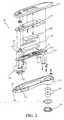
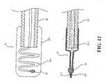
FIG. 1 is a perspective view of an electronic clinical thermometer according to the present invention.FIG. 2 is a perspective exploded view of an electronic clinical thermometer according to the present invention.FIG. 3 is a perspective exploded view of the temperature sensor of an electronic clinical thermometer according to the present invention.FIG. 4 is a perspective exploded view showing the separation of the measuring body with the temperature sensor of an electronic clinical thermometer according to the present invention.FIG. 5 is a sectional view of an electronic clinical thermometer according to the present invention.FIG. 6 is a circuit diagram of the incomplete electronic temperature measuring circuit of an electronic clinical thermometer according to the present invention.FIGS. 7 to 9 are schematic views showing the connector of preferred embodiment according to the present invention.FIG. 10 is a schematic view showing the temperature sensing device of the present invention.FIG. 11 is a schematic view of the measuring probe according to the present invention.FIG. 12 is a schematic view of the measuring probe of another preferred embodiment according to the present invention.FIG. 13 is a perspective view of an electronic clinical thermometer according to the present invention.- The following descriptions are of exemplary embodiments only, and are not intended to limit the scope, applicability or configuration of the invention in any way. Rather, the following description provides a convenient illustration for implementing exemplary embodiments of the invention. Various changes to the described embodiments may be made in the function and arrangement of the elements described without departing from the scope of the invention as set forth in the appended claims.
- Referring to
FIGS. 1 ,2 , and3 , the electronic clinical thermometer according to the present invention comprises two detachable modules, i.e. themeasuring body 10 and thesensing device 20. - The
measuring body 10 comprises atop cover 11 and abottom cover 12 made from hard plastic material. The front section of thebottom cover 12 is formed with aslot 121 on the top and arecess 122 on the bottom. Two lateral sides of the front section of thebottom cover 12 are each formed with anengaging block 123. Thebottom cover 12 is provided with abattery cover 124 for holding batteries. The measuringbody 10 contains a flexible orrigid circuit board 13 and a core 14 mounted with each other for the connection with apower switch 131, a display 132 (such as an LCD), abuzzer 133, and a light generator 134 (such as an LED). Theswitch 131 and thelight generator 134 slightly protrude out of the surface of the measuringbody 10. Thebuzzer 133 is mounted in anopening 1331 of thecircuit board 13. Thebuzzer 133 is shaped as a sheet member and is not a conventional box-like member, thereby effectively reducing its volume. When the power is turned on, the measured temperature is stabilized, or the power is turned off, thebuzzer 133 will make a humming sound and thelight generator 132 will give light to notify the user. The rear of thedisplay 132 is provided with abacklight plate 15, and theIC board 13 is provided with an incomplete electronic temperature measuring circuit (seeFIG. 6 ) which comprises a controlling integrated circuit and externally connected electronic components, lacking at least two elements, i.e. the reference resistor and temperature sensor for use in oscillation. When thepower switch 131 is turned on, due to the fact that the electronic clinical thermometer is incomplete, it is impossible to carry out temperature measurement, and thedisplay 132 will show error such as Err. Only when incomplete circuit of the measuringbody 10 is connected to the reference resistor and the temperature sensor of thesensing device 20 via a connection structure to form a complete circuit will the electronic clinical thermometer be able to measure the temperature of a patient. The measuringbody 10 includes largely the measuring circuit for processing the temperature signal obtained by thesensing device 20 and converts the signal into data which is then shown in thedisplay 132. - The
temperature sensing device 20 is an independent member externally formed from a hard plastic material and comprises a measuringprobe 21, a temperature-sensingsection 22, aconnection seat 23 and at least two electronic elements containing atemperature sensor 24 and areference resistor 25. Thetemperature sensor 24 and thereference resistance 25 may be a resistance matching module, wherein the resistance difference of thereference resistance 25 and thesensor 24 at a specific temperature (the general environmental temperature is set as follows: 25°C for thereference resistor 25 and 37°C for the temperature sensor 24) must be within a specific range. Theconnection seat 23 is a hollow member provided at the top with anotch 231 and at the two lateral sides with anengaging slot 232 which is configured to engage with theengaging block 123 of thebottom cover 12. The inner side of the top front portion of theconnection seat 23 has aprotuberance 233 adapted to engage with theslot 121 of thebottom cover 12. Thetemperature sensor 24 is fitted in the measuringprobe 21 and the end of theconductive wire 241 of thetemperature sensor 24 and other electronic elements are fixedly connected to a connector (seeFIG. 6 ). When thesensing device 20 and the measuringbody 10 are connected via a connector (as shown inFIG. 6 ), the incomplete measuring circuit of the measuringbody 10 is connected via a metal plate to thetemperature sensor 24 and thereference resistor 25 of thesensing device 20 to form into an effective complete temperature measuring circuit. At this instance, thepower switch 131 is turned on automatically or manually and the thermometer is ready to proceed to measuring temperature. - The connection structure is positioned between the measuring
body 10 and thesensing device 20. As shown inFIG. 2 , thecircuit board 13 is provided with acap 135 for keeping a plurality of resilientconductive members 136 on thecircuit board 13. The resilientconductive members 13 protrude partially out thecap 135. Theconnection seat 23 is formed with a slidingslot 234 for the mounting of acontrol board 26 having one side being connected to the conductive wire 242 of thetemperature sensor 24. The surface of thecontrol board 26 is provided withmetal contacts 261 for the mounting of thereference resistor 25. - Referring to
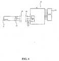
FIGS. 4 and5 , when thesensing device 20 is connected with the measuringbody 10, the engagingslot 232 of theconnection seat 23 will engage with theengaging block 123 of the measuringbody 10 thereby forming a complete electronic clinical thermometer. At this instance, theprotuberance 233 of theconnection seat 23 is engaged with theslot 121 of the measuringbody 10 so that thesensing device 20 will not be dislocated after the connection with the measuringbody 10. - Referring to
FIGS. 4 ,5 and6 , when the measuringbody 10 is connected with thesensing device 20, themetal contacts 261 of thecontrol board 26 will get into touch with the resilientconductive members 136 so that the incomplete electronic clinical thermometer circuit of the measuringbody 10 will be connected with thereference resistor 25 and thetemperature sensor 26 of thesensing device 20 to form an effective complete temperature measuring circuit with measuring error within a specific range. At this instance, when the measuringbody 10 is connected with thesensing device 20, the thermometer will be triggered automatically or manually by turning on thepower switch 131 to activate the electronic temperature measuring circuit to generate measuring signals until a steady temperature is obtained. - Hence, the
independent measuring body 10 can be used with a plurality oftemperature sensing devices 20 because thetemperature sensing devices 20 are disposable and re-usable. It can be used by multiple users at home or in hospitals. Thetemperature sensing device 20 is a module which is easy to manufacture, low in cost, and easily sterilized, thus preventing infection. - The
display 132 of the measuringbody 10 is provided with abacklight plate 15 and the control circuit is provided with a delay circuit and a reset circuit, so that when the measured temperature is stabilized, thebuzzer 133 will make a humming sound and thelight generator 134 will give light to notify the user that a steady temperature is obtained. Within a preset time period after the steady temperature signal is obtained, thebacklight plate 15 will be activated to give light for about 5 to 10 seconds. If the user cannot read the temperature clearly within that period of time, he or she may depress and hold thepower switch 131 so thatbacklight plate 15 will give light until thepower switch 131 is released and turned off - The measured result of the
sensing device 20 can be wirelessly transmitted to the central control system of the measuringbody 10 by way of wireless. A wireless transmitter may be arranged in thesensing device 20 and a wireless transmission circuit is mounted in the incomplete electronic measuring circuit so as to transmit the measured result to the central control system. - In the fabrication of the electronic clinical thermometer, the resistance matching module is regarded as a unit. The resistance matching module with the
reference resistor 25 and thetemperature sensor 24 having a resistance difference with a specific range at a specific temperature is welded via the connection structure onto the incomplete electronic temperature measuring circuit board, such that the incomplete electronic temperature measuring circuit board is formed into an effective complete electronic temperature measuring circuit and can be mounted within the housing of the thermometer casing without adjusting the difference value thereby forming an Impact Medical Thermometer. - Referring to
FIGS. 7 ,8 ,9 , the connection structure is a conductive member between the measuringbody 10 and thesensing device 20. The connection structure may be a pin header to socket (seeFIG. 7 ), an edge card to socket (seeFIG. 8 ), a metal string to Simm card (seeFIG. 9 ), or any other connection structure which can achieve the same conductive result. As shown inFIG. 13 , the connection structure is asocket 16 and apin 27 which can be used for current conduction and signal transmission. - Referring to
FIG. 10 , thetemperature sensing section 22 can be cleaned with hard or soft fabric material and if it is necessary to increase the length, a plastic covered wire can be used. - Referring to
FIG. 10 , thetemperature sensing section 22 connected to the measuringprobe 21 of thesensing device 20 may be made of rigid or soft material. When it is necessary to extend the length of thesensing section 22 for facilitating cleaning, sterilizing and using, thesensing section 22 may be made of a cord with plastic covering. - As shown in
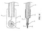
FIGS. 11 ,12 , the measuringprobe 21 can be made of stacked metal films (such as aluminum foil) 211, 212 with good conductivity. At this instance, thetemperature sensor 24 and a part of theconductive wire 241 are positioned between themetal firms conductive wire 241 can be concentrically coiled or arranged into a wave shape.
Claims (5)
- An electronic clinical thermometer comprising:a measuring body (10) including a power switch (131), a display (132) and a circuit board (13);a temperature sensing device (20) connected with the measuring body (10) through a connection structure;the temperature sensing device (20) including a measuring probe (21), a temperature sensing section (22), a connection seat (23), a reference resistor (25) and a temperature sensor (24) to form a resistance matching module having a resistance difference with a specific range at a specific temperature (24,25); anda connection structure being mounted between said measuring body (10) and said temperature-sensing device (20)characterized in that the connection structure comprises a cap (135) for keeping a plurality of resilient conductive members (136) to contact said circuit board (13) of said measuring body (10) with the temperature sensing device (20); wherein
the resilient conductive members (136) protrude partially out of said cap (135);
the connection seat (23) has a sliding slot (234) formed thereon for mounting a control board (26) to conductive wires (241) of said temperature sensor (24); and
said control board (26) is provided with metal contacts (261) for mounting said reference resistor (25); whereby when said measuring body (10) is connected with said temperature sensing device (20) the metal contacts (261) of the control board (26) will get into touch with the resilient conduction members (136) so that the circuit board (13) of the measuring body will be connected with the reference resistor (25) and the temperature sensor (26) of the temperature sensing device (20) to form an effective and complete temperature measuring circuit. - The electronic clinical thermometer of claim 1, wherein said measuring body (10) comprises a top cover (11) and a bottom cover (12) made from hard plastic material, a front section of said bottom cover (12) being formed with a slot (121) on a top and a recess (122) on a bottom, and two lateral sides of said front section of said bottom cover (12) being each formed with an engaging block (123).
- The electronic clinical thermometer of claim 1, wherein the measuring body (10) is provided with a battery cover (124) and said power switch (131), said display (132), a buzzer (133), and a light generator (134) are mounted said circuit board (13).
- The electronic clinical thermometer of claim 1, wherein said connection seat (23) is a hollow member provided at a top with a notch (231) and at two lateral sides with an engaging slot (232) which is configured to engage with an engaging block (123) of a bottom cover (12), an inner side of a top front portion of said connection seat (23) having a protuberance (233) adapted to engage with a slot (121) of said bottom cover (12).
- The electronic clinical thermometer of claim 1, wherein said measuring probe (21) is made of stacked metal films (211,212) with good conductivity, said temperature sensor (24) and a part of said conductive wire (241) being positioned between said stacked metal films (211,212), and said conductive wire (241) is concentrically coiled or arranged into a wave shape.
Priority Applications (2)
| Application Number | Priority Date | Filing Date | Title |
|---|---|---|---|
| ES03079074TES2385346T3 (en) | 2003-12-14 | 2003-12-14 | Clinical electronic thermometer with detachable probe |
| EP03079074AEP1643228B1 (en) | 2003-12-14 | 2003-12-14 | Electronic clinical thermometer with a detachable probe |
Applications Claiming Priority (1)
| Application Number | Priority Date | Filing Date | Title |
|---|---|---|---|
| EP03079074AEP1643228B1 (en) | 2003-12-14 | 2003-12-14 | Electronic clinical thermometer with a detachable probe |
Publications (2)
| Publication Number | Publication Date |
|---|---|
| EP1643228A1 EP1643228A1 (en) | 2006-04-05 |
| EP1643228B1true EP1643228B1 (en) | 2012-05-23 |
Family
ID=34924044
Family Applications (1)
| Application Number | Title | Priority Date | Filing Date |
|---|---|---|---|
| EP03079074AExpired - LifetimeEP1643228B1 (en) | 2003-12-14 | 2003-12-14 | Electronic clinical thermometer with a detachable probe |
Country Status (2)
| Country | Link |
|---|---|
| EP (1) | EP1643228B1 (en) |
| ES (1) | ES2385346T3 (en) |
Cited By (1)
| Publication number | Priority date | Publication date | Assignee | Title |
|---|---|---|---|---|
| USD1008823S1 (en) | 2020-08-17 | 2023-12-26 | SoCal Dab Tools, LLC | Temperature sensor |
Families Citing this family (7)
| Publication number | Priority date | Publication date | Assignee | Title |
|---|---|---|---|---|
| EP2159557A1 (en)* | 2008-08-28 | 2010-03-03 | Microlife Intellectual Property GmbH | Clinical electronic thermometer and method of operation thereof |
| DE102011012175A1 (en)* | 2011-02-23 | 2012-08-23 | Heraeus Electro-Nite International N.V. | Sensor arrangement for measuring parameters in melts |
| CN103256997B (en)* | 2013-05-13 | 2015-09-09 | 曾建新 | A kind of Miniature rapid body temperature induction installation |
| GB2523731A (en)* | 2014-02-03 | 2015-09-09 | Navitas Digital Safety Ltd | Device for measuring the temperature of food |
| US9943232B2 (en) | 2014-02-03 | 2018-04-17 | Welch Allyn, Inc. | Thermometry heating and sensing assembly |
| CN104970776B (en)* | 2015-07-03 | 2018-06-22 | 深圳掌康科技有限公司 | A kind of body temperature detection method and a kind of Dynamic High-accuracy calibration electric body-temperature counter device |
| CN118392313B (en)* | 2024-05-07 | 2024-09-27 | 江苏苏仪集团有限公司 | Early warning mechanism of electronic thermometer |
Family Cites Families (8)
| Publication number | Priority date | Publication date | Assignee | Title |
|---|---|---|---|---|
| US4062104A (en)* | 1975-09-05 | 1977-12-13 | Walter Norman Carlsen | Disposable clinical thermometer probe |
| JPS58200118A (en)* | 1982-05-18 | 1983-11-21 | Seiko Instr & Electronics Ltd | Electronic clinical thermometer |
| JPH076849B2 (en)* | 1984-06-13 | 1995-01-30 | オムロン株式会社 | Electronic thermometer |
| JPS61243334A (en)* | 1985-04-19 | 1986-10-29 | Citizen Watch Co Ltd | Separate type electronic thermometer |
| JPS61296228A (en)* | 1985-06-24 | 1986-12-27 | Matsushita Electric Works Ltd | Electronic clinical thermometer |
| JPH01311235A (en)* | 1988-06-09 | 1989-12-15 | Terumo Corp | Probe attachment and detachment type electronic clinical thermometer |
| US5575563A (en)* | 1993-07-15 | 1996-11-19 | Chiu; Job | Multiusage thermometer |
| DE20106011U1 (en)* | 2001-04-05 | 2001-08-09 | Mesure Technology Co., Ltd., San Chung, Taipeh | Thermometer with interchangeable measuring heads |
- 2003
- 2003-12-14EPEP03079074Apatent/EP1643228B1/ennot_activeExpired - Lifetime
- 2003-12-14ESES03079074Tpatent/ES2385346T3/ennot_activeExpired - Lifetime
Cited By (1)
| Publication number | Priority date | Publication date | Assignee | Title |
|---|---|---|---|---|
| USD1008823S1 (en) | 2020-08-17 | 2023-12-26 | SoCal Dab Tools, LLC | Temperature sensor |
Also Published As
| Publication number | Publication date |
|---|---|
| EP1643228A1 (en) | 2006-04-05 |
| ES2385346T3 (en) | 2012-07-23 |
Similar Documents
| Publication | Publication Date | Title |
|---|---|---|
| US6976783B2 (en) | Assembly method and structure of an electronic clinical thermometer | |
| US7293915B2 (en) | Assembly method and structure of an electronic clinical thermometer | |
| EP1783469B1 (en) | Electronic thermometer with flex circuit location | |
| US9183719B2 (en) | Human safety indicator | |
| US6794990B2 (en) | Electronic patch thermometer | |
| US20020163955A1 (en) | Detachable probe mounting arrangement for an electronic clinical thermometer | |
| KR20090065180A (en) | Body Thermometer and Body Temperature Measurement System | |
| WO2006009585A8 (en) | Medical body core thermometer | |
| JP3161231U (en) | Pacifier thermometer | |
| EP1643228B1 (en) | Electronic clinical thermometer with a detachable probe | |
| CN214667279U (en) | Wearable intelligent body temperature monitoring device | |
| US8556503B2 (en) | Electronic clinical thermometer | |
| US8038346B2 (en) | Detachable electronic pacifier thermometer | |
| JPH0866374A (en) | Temperature measurement instrument with pulse measurement function | |
| JP6951805B1 (en) | thermometer | |
| JPH0866373A (en) | Temperature measurement instrument with pulse measurement function | |
| CN207370702U (en) | Split type micro radio electron temperature meter and Thermometer System | |
| CN112617826A (en) | Blood oxygen body temperature detector and blood oxygen body temperature detection system | |
| CN2343581Y (en) | Applicable to multi-part warning thermometers on the body surface | |
| WO2000004353A1 (en) | Radiation thermometer | |
| JPH0529504U (en) | Temperature measuring instrument with pulse measurement function | |
| US20070293784A1 (en) | Temperature monitoring apparatus | |
| CN120253004A (en) | An electronic thermometer | |
| CN204618201U (en) | A kind of clinical thermometer | |
| JP2555918Y2 (en) | Temperature measuring instrument with pulse measurement function |
Legal Events
| Date | Code | Title | Description |
|---|---|---|---|
| PUAI | Public reference made under article 153(3) epc to a published international application that has entered the european phase | Free format text:ORIGINAL CODE: 0009012 | |
| 17P | Request for examination filed | Effective date:20031214 | |
| AK | Designated contracting states | Kind code of ref document:A1 Designated state(s):AT BE BG CH CY CZ DE DK EE ES FI FR GB GR HU IE IT LI LU MC NL PT RO SE SI SK TR | |
| AX | Request for extension of the european patent | Extension state:AL LT LV MK | |
| AKX | Designation fees paid | Designated state(s):AT BE BG CH CY CZ DE DK EE ES FI FR GB GR HU IE IT LI LU MC NL PT RO SE SI SK TR | |
| 17Q | First examination report despatched | Effective date:20090327 | |
| GRAP | Despatch of communication of intention to grant a patent | Free format text:ORIGINAL CODE: EPIDOSNIGR1 | |
| RAP1 | Party data changed (applicant data changed or rights of an application transferred) | Owner name:ACTHERM INC. | |
| GRAS | Grant fee paid | Free format text:ORIGINAL CODE: EPIDOSNIGR3 | |
| GRAL | Information related to payment of fee for publishing/printing deleted | Free format text:ORIGINAL CODE: EPIDOSDIGR3 | |
| GRAS | Grant fee paid | Free format text:ORIGINAL CODE: EPIDOSNIGR3 | |
| GRAA | (expected) grant | Free format text:ORIGINAL CODE: 0009210 | |
| AK | Designated contracting states | Kind code of ref document:B1 Designated state(s):AT BE BG CH CY CZ DE DK EE ES FI FR GB GR HU IE IT LI LU MC NL PT RO SE SI SK TR | |
| REG | Reference to a national code | Ref country code:GB Ref legal event code:FG4D | |
| REG | Reference to a national code | Ref country code:CH Ref legal event code:EP | |
| REG | Reference to a national code | Ref country code:AT Ref legal event code:REF Ref document number:559291 Country of ref document:AT Kind code of ref document:T Effective date:20120615 | |
| REG | Reference to a national code | Ref country code:IE Ref legal event code:FG4D | |
| REG | Reference to a national code | Ref country code:ES Ref legal event code:FG2A Ref document number:2385346 Country of ref document:ES Kind code of ref document:T3 Effective date:20120723 | |
| REG | Reference to a national code | Ref country code:DE Ref legal event code:R096 Ref document number:60340991 Country of ref document:DE Effective date:20120726 | |
| REG | Reference to a national code | Ref country code:NL Ref legal event code:VDEP Effective date:20120523 | |
| PG25 | Lapsed in a contracting state [announced via postgrant information from national office to epo] | Ref country code:SE Free format text:LAPSE BECAUSE OF FAILURE TO SUBMIT A TRANSLATION OF THE DESCRIPTION OR TO PAY THE FEE WITHIN THE PRESCRIBED TIME-LIMIT Effective date:20120523 Ref country code:CY Free format text:LAPSE BECAUSE OF FAILURE TO SUBMIT A TRANSLATION OF THE DESCRIPTION OR TO PAY THE FEE WITHIN THE PRESCRIBED TIME-LIMIT Effective date:20120523 Ref country code:FI Free format text:LAPSE BECAUSE OF FAILURE TO SUBMIT A TRANSLATION OF THE DESCRIPTION OR TO PAY THE FEE WITHIN THE PRESCRIBED TIME-LIMIT Effective date:20120523 | |
| REG | Reference to a national code | Ref country code:AT Ref legal event code:MK05 Ref document number:559291 Country of ref document:AT Kind code of ref document:T Effective date:20120523 | |
| PG25 | Lapsed in a contracting state [announced via postgrant information from national office to epo] | Ref country code:SI Free format text:LAPSE BECAUSE OF FAILURE TO SUBMIT A TRANSLATION OF THE DESCRIPTION OR TO PAY THE FEE WITHIN THE PRESCRIBED TIME-LIMIT Effective date:20120523 Ref country code:GR Free format text:LAPSE BECAUSE OF FAILURE TO SUBMIT A TRANSLATION OF THE DESCRIPTION OR TO PAY THE FEE WITHIN THE PRESCRIBED TIME-LIMIT Effective date:20120824 Ref country code:PT Free format text:LAPSE BECAUSE OF FAILURE TO SUBMIT A TRANSLATION OF THE DESCRIPTION OR TO PAY THE FEE WITHIN THE PRESCRIBED TIME-LIMIT Effective date:20120924 | |
| PG25 | Lapsed in a contracting state [announced via postgrant information from national office to epo] | Ref country code:BE Free format text:LAPSE BECAUSE OF FAILURE TO SUBMIT A TRANSLATION OF THE DESCRIPTION OR TO PAY THE FEE WITHIN THE PRESCRIBED TIME-LIMIT Effective date:20120523 | |
| PG25 | Lapsed in a contracting state [announced via postgrant information from national office to epo] | Ref country code:NL Free format text:LAPSE BECAUSE OF FAILURE TO SUBMIT A TRANSLATION OF THE DESCRIPTION OR TO PAY THE FEE WITHIN THE PRESCRIBED TIME-LIMIT Effective date:20120523 Ref country code:RO Free format text:LAPSE BECAUSE OF FAILURE TO SUBMIT A TRANSLATION OF THE DESCRIPTION OR TO PAY THE FEE WITHIN THE PRESCRIBED TIME-LIMIT Effective date:20120523 Ref country code:SK Free format text:LAPSE BECAUSE OF FAILURE TO SUBMIT A TRANSLATION OF THE DESCRIPTION OR TO PAY THE FEE WITHIN THE PRESCRIBED TIME-LIMIT Effective date:20120523 Ref country code:DK Free format text:LAPSE BECAUSE OF FAILURE TO SUBMIT A TRANSLATION OF THE DESCRIPTION OR TO PAY THE FEE WITHIN THE PRESCRIBED TIME-LIMIT Effective date:20120523 Ref country code:EE Free format text:LAPSE BECAUSE OF FAILURE TO SUBMIT A TRANSLATION OF THE DESCRIPTION OR TO PAY THE FEE WITHIN THE PRESCRIBED TIME-LIMIT Effective date:20120523 Ref country code:CZ Free format text:LAPSE BECAUSE OF FAILURE TO SUBMIT A TRANSLATION OF THE DESCRIPTION OR TO PAY THE FEE WITHIN THE PRESCRIBED TIME-LIMIT Effective date:20120523 Ref country code:AT Free format text:LAPSE BECAUSE OF FAILURE TO SUBMIT A TRANSLATION OF THE DESCRIPTION OR TO PAY THE FEE WITHIN THE PRESCRIBED TIME-LIMIT Effective date:20120523 | |
| REG | Reference to a national code | Ref country code:DE Ref legal event code:R097 Ref document number:60340991 Country of ref document:DE | |
| PLBE | No opposition filed within time limit | Free format text:ORIGINAL CODE: 0009261 | |
| STAA | Information on the status of an ep patent application or granted ep patent | Free format text:STATUS: NO OPPOSITION FILED WITHIN TIME LIMIT | |
| 26N | No opposition filed | Effective date:20130226 | |
| REG | Reference to a national code | Ref country code:DE Ref legal event code:R082 Ref document number:60340991 Country of ref document:DE Representative=s name:LANGPATENT ANWALTSKANZLEI IP LAW FIRM, DE Ref country code:DE Ref legal event code:R082 Ref document number:60340991 Country of ref document:DE Representative=s name:LANGPATENT ANWALTSKANZLEI, DE | |
| REG | Reference to a national code | Ref country code:DE Ref legal event code:R097 Ref document number:60340991 Country of ref document:DE Effective date:20130226 | |
| PG25 | Lapsed in a contracting state [announced via postgrant information from national office to epo] | Ref country code:BG Free format text:LAPSE BECAUSE OF FAILURE TO SUBMIT A TRANSLATION OF THE DESCRIPTION OR TO PAY THE FEE WITHIN THE PRESCRIBED TIME-LIMIT Effective date:20120823 Ref country code:MC Free format text:LAPSE BECAUSE OF NON-PAYMENT OF DUE FEES Effective date:20121231 | |
| REG | Reference to a national code | Ref country code:CH Ref legal event code:PL | |
| REG | Reference to a national code | Ref country code:IE Ref legal event code:MM4A | |
| PG25 | Lapsed in a contracting state [announced via postgrant information from national office to epo] | Ref country code:LI Free format text:LAPSE BECAUSE OF NON-PAYMENT OF DUE FEES Effective date:20121231 Ref country code:IE Free format text:LAPSE BECAUSE OF NON-PAYMENT OF DUE FEES Effective date:20121214 Ref country code:CH Free format text:LAPSE BECAUSE OF NON-PAYMENT OF DUE FEES Effective date:20121231 | |
| PGFP | Annual fee paid to national office [announced via postgrant information from national office to epo] | Ref country code:DE Payment date:20131230 Year of fee payment:11 Ref country code:GB Payment date:20131227 Year of fee payment:11 | |
| PGFP | Annual fee paid to national office [announced via postgrant information from national office to epo] | Ref country code:ES Payment date:20131226 Year of fee payment:11 Ref country code:IT Payment date:20131223 Year of fee payment:11 Ref country code:FR Payment date:20131217 Year of fee payment:11 | |
| PG25 | Lapsed in a contracting state [announced via postgrant information from national office to epo] | Ref country code:TR Free format text:LAPSE BECAUSE OF FAILURE TO SUBMIT A TRANSLATION OF THE DESCRIPTION OR TO PAY THE FEE WITHIN THE PRESCRIBED TIME-LIMIT Effective date:20120523 | |
| PG25 | Lapsed in a contracting state [announced via postgrant information from national office to epo] | Ref country code:LU Free format text:LAPSE BECAUSE OF NON-PAYMENT OF DUE FEES Effective date:20121214 | |
| PG25 | Lapsed in a contracting state [announced via postgrant information from national office to epo] | Ref country code:HU Free format text:LAPSE BECAUSE OF FAILURE TO SUBMIT A TRANSLATION OF THE DESCRIPTION OR TO PAY THE FEE WITHIN THE PRESCRIBED TIME-LIMIT Effective date:20031214 | |
| REG | Reference to a national code | Ref country code:DE Ref legal event code:R119 Ref document number:60340991 Country of ref document:DE | |
| GBPC | Gb: european patent ceased through non-payment of renewal fee | Effective date:20141214 | |
| REG | Reference to a national code | Ref country code:FR Ref legal event code:ST Effective date:20150831 | |
| PG25 | Lapsed in a contracting state [announced via postgrant information from national office to epo] | Ref country code:DE Free format text:LAPSE BECAUSE OF NON-PAYMENT OF DUE FEES Effective date:20150701 Ref country code:GB Free format text:LAPSE BECAUSE OF NON-PAYMENT OF DUE FEES Effective date:20141214 | |
| PG25 | Lapsed in a contracting state [announced via postgrant information from national office to epo] | Ref country code:FR Free format text:LAPSE BECAUSE OF NON-PAYMENT OF DUE FEES Effective date:20141231 | |
| PG25 | Lapsed in a contracting state [announced via postgrant information from national office to epo] | Ref country code:IT Free format text:LAPSE BECAUSE OF NON-PAYMENT OF DUE FEES Effective date:20141214 | |
| PG25 | Lapsed in a contracting state [announced via postgrant information from national office to epo] | Ref country code:ES Free format text:LAPSE BECAUSE OF NON-PAYMENT OF DUE FEES Effective date:20141215 |