EP1642253B1 - Display device having an extendible screen - Google Patents
Display device having an extendible screenDownload PDFInfo
- Publication number
- EP1642253B1 EP1642253B1EP04743028AEP04743028AEP1642253B1EP 1642253 B1EP1642253 B1EP 1642253B1EP 04743028 AEP04743028 AEP 04743028AEP 04743028 AEP04743028 AEP 04743028AEP 1642253 B1EP1642253 B1EP 1642253B1
- Authority
- EP
- European Patent Office
- Prior art keywords
- screen
- side member
- display device
- extended
- extendible
- Prior art date
- Legal status (The legal status is an assumption and is not a legal conclusion. Google has not performed a legal analysis and makes no representation as to the accuracy of the status listed.)
- Expired - Lifetime
Links
Images


Classifications
- G—PHYSICS
- G06—COMPUTING OR CALCULATING; COUNTING
- G06F—ELECTRIC DIGITAL DATA PROCESSING
- G06F1/00—Details not covered by groups G06F3/00 - G06F13/00 and G06F21/00
- G06F1/16—Constructional details or arrangements
- G06F1/1601—Constructional details related to the housing of computer displays, e.g. of CRT monitors, of flat displays
- G—PHYSICS
- G06—COMPUTING OR CALCULATING; COUNTING
- G06F—ELECTRIC DIGITAL DATA PROCESSING
- G06F1/00—Details not covered by groups G06F3/00 - G06F13/00 and G06F21/00
- G06F1/16—Constructional details or arrangements
- G—PHYSICS
- G09—EDUCATION; CRYPTOGRAPHY; DISPLAY; ADVERTISING; SEALS
- G09F—DISPLAYING; ADVERTISING; SIGNS; LABELS OR NAME-PLATES; SEALS
- G09F9/00—Indicating arrangements for variable information in which the information is built-up on a support by selection or combination of individual elements
- G09F9/30—Indicating arrangements for variable information in which the information is built-up on a support by selection or combination of individual elements in which the desired character or characters are formed by combining individual elements
- G09F9/301—Indicating arrangements for variable information in which the information is built-up on a support by selection or combination of individual elements in which the desired character or characters are formed by combining individual elements flexible foldable or roll-able electronic displays, e.g. thin LCD, OLED
- H—ELECTRICITY
- H04—ELECTRIC COMMUNICATION TECHNIQUE
- H04M—TELEPHONIC COMMUNICATION
- H04M1/00—Substation equipment, e.g. for use by subscribers
- H04M1/02—Constructional features of telephone sets
- H04M1/0202—Portable telephone sets, e.g. cordless phones, mobile phones or bar type handsets
- H04M1/026—Details of the structure or mounting of specific components
- H04M1/0266—Details of the structure or mounting of specific components for a display module assembly
- H04M1/0268—Details of the structure or mounting of specific components for a display module assembly including a flexible display panel
Definitions
- the present inventionrelates to a display device having an extendible screen.
- WO-A-2002/47363discloses a telephone having a retractable screen. Hinged support members may be assembled into a framework to which the end of the screen can be attached when extended.
- WO-A-2003/043294discloses a telephone having a retractable screen and telescopic members to which the end of the screen is attached.
- a display devicecomprising: an extendible screen that is extendible in an extension direction from a relatively compact form to an extended form, the display device having or being connectable to drive circuitry for driving the display of the screen, the screen in the extended form having opposed edges that are substantially parallel to the extension direction; and, at least one of said opposed edges having an extendible side member, characterised in that the at least one opposed edge has the extendible side member connected thereto, and in that the or each extendible side member is extendible to provide support to and structural rigidity to the opposed edge of the screen to which it is connected when the screen is in the extended form.
- the present inventionprovides an extendible screen with at least one extendible side member in order to provide at least some structural rigidity to the screen when in the extended form.
- the display deviceis capable of being arranged in a compact form, for example for storage or transportation purposes. However it is also capable of being deployed with the screen in at least one extended form, with the or each side member also extending to provide support to the screen.
- the structural rigidity given to the extended screenallows it to be used in a wider range of applications than would otherwise be possible.
- the screenis capable of being placed on an irregular surface whilst still retaining its flatness. This is in contrast to prior art devices with flexible screens but no support which would need to be held in position by external means or placed on a flat surface of sufficient size.
- the support given to the screencan allow the device to be held in one hand, leaving the other hand to provide input to the device for example.
- the screenis also more suitable to incorporate a touch-sensitive input device.
- the support and rigidity given to the screen by the or each side memberallows the flexible screen to receive touch input without deforming under the pressure of the input.
- the side memberprovides a solid edge which protects the potentially delicate edge of the screen.
- the side memberalso gives the display device a more solid, robust look and feel. Overall this provides the advantage of a solid tablet display with significantly increased portability and flexibility in terms of screen size and application.
- the display devicecomprises a respective extendible side member for each of said opposed edges. This gives greater structural rigidity to the display device and more complete protection from damage to the potentially delicate edges of the screen.
- the screencan be tautly suspended between the two side members providing further support to the screen.
- the or at least one of the side membersis provided by a bistable material having a first stable state when said side member is extended and a second stable state when said side member is not extended.
- Bistable materials per seare known and are capable of forming two stable structural forms (see US-B-6256938 and US-B-6217975 for example).
- a bistable materialcan transform between a first stable form and a second stable form and are typically capable of' bearing significant physical loads when in their stable forms.
- theycan be employed in the present invention to provide side members that have a first stable form in which the side members are in a compact form and a second stable form in which the side members are in an extended form, and are capable of bearing load.
- the preferred bistable materialcan exist with one end in one stable form and the other end in a second stable form, the bistable material therefore being capable of forming extendible side members that can be extended to any desired length.
- the screenis extendible to and lockable at an intermediate position between said relatively compact form and said extended form, the or each side member being extendible to provide support to and structural rigidity to the screen when the screen is in the intermediate position.
- the screencan thus be extended to the desired size according to the application and locked into position.
- a screen of the desired sizecan thus be formed, such sizes including for example a large "tablet” computer mode, a "widescreen” for play back of movies, an A4 size screen for displaying documents or web pages, and a smaller A5 size screen for use with a PDA device.
- the side membersalso provide a uniform appearance of the device at each size.
- the display devicecomprises a bar extending between said opposed edges, the bar being fixed to the screen and the or each side member.
- a barcan be used to aid in the extension and/or retraction of the screen.
- the barcan be fixed to the screen and the or each side member to set their relative position and to ensure that their correct alignment is maintained.
- the barcan be used to mark the midpoint, or any other convenient point, of the screen to provide a reference point, and used to fix the or each side member in its load-bearing form at its midpoint. This can be achieved in a simple way in a preferred embodiment by providing the bar with an end profile shaped to lock the side member in its load bearing form.
- the barcan be used to define a boundary defining which part of the screen is rolled about which axis. The bar can also be used as part of a mechanism to implement this.
- the display devicemay comprise a locking mechanism for locking the or at least one of the side members in its extended form.
- the display devicecomprises at least one housing which at least partially accommodates the screen when in said relatively compact form, wherein the or at least one of the side members is at least partially accommodated by the housing when the screen is in said relatively compact form.
- the housingpreferably has a guide aperture through which said side member passes on extension or retraction of the screen in order to guide the movement of said side member between the extended and retracted states of said side member. This is particularly useful in the case of the side member being formed from a bistable material because the guide apertures can be shaped to aid the transition between the two stable states of the side member as it passes through the aperture.
- At least one of said opposed edges of the screenhas a groove which receives a tongue of the corresponding side member when the screen is in the extended form.
- the tongueis provided by an edge of the side member.
- Such an arrangementcan be dynamically formed, meaning that, in an embodiment where a guide aperture is provided, each part of the tongue and groove engage with each other as and when they are extended through the guide aperture. Accordingly when the screen and side member(s) are not extended, they can be stored separately from each other. This allows the two to be stored in different fashions, allowing flexibility in the storage arrangements (and manufacture) of the screen and side member(s) and therefore permitting the compact form of the device to be small.
- At least one of said opposed edges of the screenhas plural projections which are received by respective plural apertures or recesses on the corresponding side member when the screen is in extended form to provide a reversible locking arrangement between said screen edge and said side member.
- the apertures/recesses and projectionsprovide a further or alternative locking arrangement between the extended portions of the screen edge and the corresponding side member to that of the tongue and groove arrangement of the previously described embodiment.
- the locking arrangement of the apertures/recesses and projectionsmay provide the same advantages as the tongue and groove arrangement.
- the locking arrangement of the apertures/recesses and projectionsrestricts relative movement between the side member and corresponding screen edge in a longitudinal direction.
- the display devicecomprises at least one guide member for at least one side member, the or each guide member being arranged to guide the side member and screen edge into or out of locking engagement on extension or retraction respectively of said side member and screen.
- the guide memberguides the side member so that the apertures/recesses of the side member disengage from the projections of the screen edge.
- the guide membermay provide the further advantage of guiding the side member and screen edge such that each is guided into a respective storage region inside the housing.
- the side memberhas a first cross-sectional shape when in its extended form and a second cross-sectional shape when in its retracted form
- the housinghas a guide aperture through which said side member passes on extension or retraction of the screen
- said side memberhas a tongue provided by an edge of said side member and the corresponding edge of said screen has a corresponding groove
- said guide apertureis arranged to guide the transition of said side member between its first and second shapes on retraction and extension of the side member respectively and to cause said tongue to engage with said groove on extension of the side member.
- the guide aperture of this embodimenthas the dual function of aiding the transition of the side member between its retracted form and its extended form as the screen is extended and retracted, and aiding the formation of the tongue and groove engagement between the side member and the screen as the side member and screen are extended.
- the screencomprises a screen backing layer formed from a plurality of substantially parallel slats arranged perpendicularly to the extension direction.
- the screencomprises a screen backing layer formed from a bistable material that has increased rigidity when planar.
- the screencomprises a screen backing layer formed from a smart material that has increased rigidity when planar and is capable of undergoing a current-assisted solid-state phase transition.
- the screenis arranged to roll from the extended form to the relatively compact form.
- the rolling screenrolls about a single axis.
- the rolling screenrolls partly about a first axis and partly about a second parallel axis.
- the display device in a preferred embodimentis capable of providing an extendible rigid screen suitable for creating a rigid collapsible tablet computer, or enabling a compact portable display to support a rigid touch-screen, or for incorporation into a mobile phone or remote control unit.
- a display device 1comprises a rollable screen 2 with two opposed side members 3.
- the rollable screen 2is rolled at each ends about one of two opposed parallel rollers 4.
- Each roller 4is mounted in a housing 5 and is free to rotate about its axis.
- An aperture 6 in the face of the housing 5allows the screen 2 to pass into and out of the housings 5.
- the arrangement of the housings 5 and rollers 4 at each end of the screen 2is identical in construction and operation and so only one will be described in detail in the following. This symmetric construction is an advantage of the preferred embodiment as it helps to keep down manufacturing costs.
- FIG. 4a detailed view of part of the housing 5 is shown.
- a pin 7which is co-aligned with the axis of the roller 4.
- Each pin 7is received by a complementary recess 8 formed in the housing 5 which holds the roller 4 in position whilst allowing it to rotate about its longitudinal axis.
- a pair of roll bar guides 9are positioned adjacent to the housing aperture 6, being positioned parallel to the roller 4, with one roll bar guide 9 above the other to form a roll bar aperture between them which is narrower than the housing aperture 6.
- This roll bar apertureacts as a guide for the screen 2 as it moves back and forth through the housing aperture 6.
- the roll bar guides 9are retained at their ends by brackets 11 formed in the interior of the housing 5.
- the brackets 11hold the roll bar guides 9 in position whilst allowing them to rotate about their axes. Hence, as well as guiding the screen 2, the smooth and rotatable nature of the roll bar guides 9 reduce frictional wear and other stresses on the screen 2 as it passes through the housing 5.
- an X-frame 12is shown attached to the two opposed housings 5.
- the X-frame 12is positioned immediately under the screen 2.
- the X frame 12is comprised of two telescopically extendible members 13, 14, which are pivoted together at their midpoints. Each end 15 of each X-frame member 13, 14 passes into the housing 5 through the housing aperture 6 and is attached to an interior surface of the respective housing 5 in such a way that allows it to pivot.
- the X-frame 12provides further structural rigidity to the display device 1.
- the X-frame 12can also be used to limit the maximum extension of the screen 2.
- One continuous, extendible side member 3is disposed at each side of the screen 2. Each end of each side member 3 is accommodated by a respective housing 5 which it enters through a guide aperture 24. As the screen 2 extends or retracts from the housing 5, the side members 3 also extend or retract from the housing 5 to provide a continuous, structurally rigid edge to the screen 2. This arrangement provides several advantages.
- the device 1provides added structural rigidity to the device 1 as a whole and to the screen 2 in particular. This gives several beneficial capabilities to the device 1 when being used in its deployed mode.
- the device 1can be held in one hand, or in both hands, or placed on an uneven surface, whilst maintaining its form.
- itprovides support and stiffness to the screen 2, allowing it to maintain its flatness. As well as providing the advantages of a flat display surface, this can also prevent damage to the screen 2 where it is made of a technology susceptible to damage from sharp bending of its surface.
- the solid edgeprovides protection for the edge of the screen 2 from damage from external sources, as well as giving the device 1 a solid, rigid look, which is substantially uniform regardless of the extended length of the screen 2.
- an extendible backing layer 32can also be provided. This can be positioned beneath the screen 2, extending between the side members 3, and in combination with the side members 3 would encase the parts of the screen 2 other than the display surface itself. This would allow circuitry or other components positioned under the screen to be hidden from view and protected from damage. This would also provide a more aesthetically pleasing, solid appearance to the device 1, which makes the device 1 more appealing to consumers, and can increase further the rigidity of the screen 2.
- the backing layer 32may be in the form of plural parallel slats which each extend across the width of the screen 2 and have increased rigidity by locking into the side member using, for example, a tongue and groove arrangement. (Such slats 35 are shown in the second example discussed below.)
- the backing layer 32can be formed, in whole or in part, from a bistable or smart material (such as a shape memory alloy) that has some increased rigidity in the flat deployed configuration.
- a bistable or smart materialsuch as a shape memory alloy
- Such a smart materialcan utilise a pseudo-elastic effect (which can be enhanced, for example, by passing a current through the layer) to increase flexibility or undergo a solid-state phase change as the screen 2 rolls about the rollers 4.
- a cross-bar 16is attached to the underside of the screen and runs across its width parallel to the rollers 4.
- the two ends of the bar 16are attached to the two side members 3 respectively.
- the cross-bar 16is positioned at the midpoint of the screen 2 and the midpoint of the two side members 3.
- the cross-bar 16serves a number of purposes. First, it acts as an additional support for the screen 2.
- the screen 2provides a permanent connection between the screen 2 and the side members 3 at their midpoints which has the effect of maintaining their correct relative alignment and holds the midpoints of the side members 3 in their load-bearing bistable form at all extensions between fully compact and fully extended.
- itacts as a reference marking the midpoint of the screen 2 which can be used when retracting the screen or extending it to the desired position.
- the cross-bar 16 and the X-frame 12can be attached to each other at their midpoints to further aid this process.
- the side members 3are formed from a bistable material, such as are known per se.
- Bistable materialshave the property of being able to take on two stable structural forms.
- a member made using a bistable materialis capable of forming two stable structures.
- Such a membercan have one of its ends in a first stable state, and the other end in a second stable state, without significant instability.
- Bistable materialsare also capable of forming members capable of bearing considerable loads. They are therefore well suited to the side members 3, as in a first stable state they can form an extended member capable of bearing load and providing support to the screen, and in a second stable state they can take on a more compact form which is stable.
- each side member 3has a cross-sectioned shape that is approximately an inverted tear-drop, though with one edge 22 slightly more inboard that the other edge 23.
- the side members 3lock to the edges of the screen 2 as the screen 2 is extended.
- a screen edge strip 17is attached to each side of the screen 2 and runs along the extent of its length.
- Each screen edge strip 17has an upper groove 18 and a lower groove 19 running along its length.
- the edges 22, 23 of the side members 3locate into the lower groove 18 and upper groove 19 respectively of the respective screen edge strips 17.
- the combination of the screen edge strip 17 with the bistable side members 3 "locked” into itprovides a structurally rigid tubular member capable of bearing considerable load. This provides structural rigidity to the display device 1 as a whole, as well as supporting the screen 2 and constraining its edges, providing resistance to deformation of the screen.
- each side member 3is almost entirely in a relatively flat form.
- the two legs of the lower V-shaped section 26close together, whilst the upper curved section 27 flattens out so the section as a whole is substantially planar.
- the end of the side member 3 which is accommodated within the housing 5takes on this relatively flat form and is accommodated by channels 28 in the rear wall of the housing 5.
- the channel 28stops short of the guide aperture 24 and the guide aperture 24 is shaped according to the two forms of the bistable material.
- the guide aperture 24has a shape intermediate the cross-sectioned shape of the side member 3 at its two stable forms.
- the guide aperture 24is shaped to correspond to the shape of the side member 3 at its transition between the two stable forms.
- sprung bearings and/or roll-barscan be positioned adjacent to the channel 28 and guide aperture 24 and arranged to aid the transition. (An example of this arrangement is shown in the second example discussed below.)
- each side member 3passes through a transition 29 at which the two legs of the lower V-section 26 spring apart and its edge 23 is guided into position to lock into groove 19 of the screen edge strip 17, whilst the upper curved section 27 curls over to allow its edge 22 to lock into the upper groove 18 of the screen edge strip 17.
- Thisprovides a "zip-fastening" effect between each side member 3 and screen edge strip 17, the side members 3 and edge strip 17 “locking" together as the side members 3 extend through their respective guide apertures 24.
- the side members 3in place of a bistable material, can be formed from a material having a single intrinsic stable form, with a second stable form being achieved by the use of a magnetic strip.
- the V-section 26 of side member 3can have a first stable form where its two legs spring apart, and a second stable form where its two legs are held together by the action of a magnet on one of the legs and exerting a magnetic attraction to a magnetic element on the other leg.
- the guide apertures 24again aid the transition between the two stable forms.
- the display device 1is in principal capable of being deployed in any intermediate configuration between the fully retracted, compact form and its fully extended form if desired.
- the display device 1is shown in its most compact form.
- the screen 2is fully retracted and the housings 5 have come together to abut each other.
- the housings 5can be locked together in this state with a latch (not shown) to prevent the device 1 from extending unintentionally.
- the screen 2is rolled about the two rollers 4, the cross-bar 16 is accommodated equally in two recesses in the housings 5, the X-frame 12 has telescopically retracted, and the side members 3 have largely retracted into the housing 5, having assumed their relatively flat form, and are accommodated in the channels 28.
- the housings 5could be manually separated until the screen 2 achieved the desired width.
- one or both rollers 4could be motor driven to allow the device to automatically produce a screen 2 of the desired width/length.
- the rollers 4could be spring loaded to bias the device 1 to a pre-selected configuration.
- a brake(not shown), such as a friction pad bearing on one or both side member 3 can be incorporated into one or both of the housings 5 to allow the screen 2 to be locked into position in either a closed or partially or fully deployed configuration. This brake may be manually or electrically operated for example.
- the display device 1it is possible for the display device 1 to be deployed in more than one configuration, allowing screens 2 of different sizes and aspect ratios to be formed appropriate to the application for which the device 1 is being used. It is possible to completely automate the deployment of the screen 2.
- Controls 30 on the housing 5may be used by the user to select an application that the device is to be utilised for (for example PDA or tablet mode). The device 1 could then automatically extend the screen 2 to the appropriate size and then lock it in place.
- the degree of screen extensioncould be determined for example by measuring the amount of rotation of the rollers 4 using electronic or optical means, such measuring techniques being known per se.
- the screen 2itself can be made from an organic LED (OLED) or polymer liquid crystal technology.
- OLEDorganic LED
- the screen 2can be combined with other technologies such as a flexible circuit control membrane to drive the display, and/or a flexible ion-polymer battery for power supply, and/or electro-luminescent cable to back-light the display.
- circuitry, batteries or other componentscan be stored inside the rollers 4, or elsewhere in the housing 5.
- a touch-sensitive screen 2can be implemented by adding charge grid technology to the screen 2. Sufficient support is given to the screen 2 to provide a substantively solid surface, permitting touch-sensitive operation.
- the X-frame 12, cross-bar 16 and particularly the side members 3all provide support to the screen 2, whilst the "zip fastening" interface between the side members 3 and the screen edge strips 17 constrain the screen edges to provide a stiffening effect, further adding to its ability to resist deformation of its surface.
- ribs or slatscan be embedded in the screen backing 32 running parallel to the rollers 4.
- Such ribsmay have a cross sectional shape that is square or rectangular or some other shape, such as a sector of a circle.
- the display device 1can also be used with a simpler screen 2, such as a static solid state screen combined with a magnetic print head/refresh bar in the housing 5 which resets the image each time the device 1 is opened. This would allow applications such as digital newspapers, key documents or web site display.
- the display device 1can be combined with other technology to provide other applications.
- CPU and other processing meanscould be encased by the housing 5.
- Communication devicescan be encased in the housing 5 to allow the device 1 to access and display web pages, for example.
- USB connectivitycan be added to allow interfacing to other external devices.
- Input devicescan be associated with the housing 5.
- pointing devicessuch as a tracker ball or mouse "nubbin" and/or hot keys can be provided in one of the housings 5 at an ergonomically suitable position.
- FIG. 8 to 14a second example of an embodiment of the present invention is shown. Like reference numerals are used for corresponding features in the first example (shown in Figures 1 to 7 ) and the second example.
- the second examplediffers from the first example only in certain features and accordingly not all features of the second example will be discussed in detail here.
- the second examplediffers from the first embodiment in that the housings 5 are more stylised, the channels 28 are positioned in front of the rollers 4 rather than in the rear wall of the housings 5, and there is a different locking arrangement concerning the side members 3 and the screen edge strips 17, which allow among other things a reduced cross-section profile of the side members 3.
- FIG 8shows the display device 1 in a deployed configuration with the lid 33 of each housing 5 removed for clarity.
- the housings 5support the rollers 4 which are attached to the screen 2 and side members 3 which are attached to the screen edge strips 17.
- the screen edge strips 17 in this exampleform the top face of the side structure rather than the interior.
- Figure 9ashows the display device 1 in its collapsed configuration.
- Fig 9bshows the profile of the screen 2 when fully stored and rolled around the rollers 4.
- Figure 9cshows the device with the lids 33 attached to the housings.
- the lids 33preferably provide a viewing window 34 to allow the screen to be partially visible in the collapsed configuration.
- Figure 10shows the display device 1 with the screen 2 and housing lids 33 not shown for clarity.
- the X-frame 12is omitted in this example as the required structural rigidity is provided to the display unit 1 in particular by the combination of the housings 5, the side members 3, the screen edge strips 17, and the screen backing slats 35.
- the roll bar guide 9comprises two upper short roll bars 41, 42 and a lower cogwheel roll bar 43 (shown only in Figure 10 for one housing 5 for clarity).
- the two upper short roll bars 41, 42are mounted at both sides of the aperture 6 adjacent to its top.
- the lower cogwheel roll bar 43extends across the width of the aperture 6 adjacent to its bottom, and comprises of two cogwheels 44, 45 mounted on a roll bar.
- Each roll-bar 41, 42, 43is mounted in the housing 5 such that it can rotate about its longitudinal axis.
- the roll bars 41, 42, 43are arranged so that the screen 5 passes between the upper roll bars 41, 42 and the lower roll bar 43 when passing through the aperture 6.
- the screen 5has support slats 35 formed on its under side 32.
- the slats 35have a cross sectional shape in the form of a (partial) sector of a circle. This cross sectional shape allows the slats 35 to engage with the recesses formed between the teeth of the two cogs 44, 45 of the lower cogwheel roll bar 43.
- As each slat 35 engages with the cogwheel roll bar 43it is constrained in its alignment to be parallel to the cogwheel roll bar 43 and thereby perpendicular to the direction in which the screen 2 is being extended or retracted. This arrangement helps maintain the screen in a rectangular/square form.
- FIG. 11 to 14detail sections of the display device 1 are shown, showing a part of one housing 5, side member 3, screen edge strip 17, etc. Accordingly, in the following discussion in relation to Figures 11 to 14 , a single instance of these features is generally described. It should be noted, however, that the description applies equally to all instances of the particular feature.
- the screen edge strip 17has two grooves 18, 19 formed in its underside running along its length.
- the screen edge strip 17comprises an underside surface sheet 38 (which may conveniently be formed of a metal), which is attached to the underside of the screen edge strip 17, running along its length, and being positioned between the two grooves 18, 19 such that its edges are approximately flush with the sides of the grooves 18, 19.
- a series of tabs or projections 37is formed in the underside surface sheet 38 on each opposed edge and runs along its length. The projections 37 overlap the underside grooves 18, 19.
- the underside surface sheet 38may be biased in order to help retract and wind the screen 3 about the rollers 4.
- each side member 3has an approximately V or Y or "wine glass” cross section shape when in its extended form.
- the end of each "leg" of the side member 3has a series of apertures or recesses or perforations 39 running along its length which correspond to the series of projections 37 on the screen edge strip 17.
- the ends of the two legs of each side member 3respectively fit into the two underside grooves 18, 19 such that the projections 37 are received by the perforations 39 in a reversible locking arrangement.
- the screen edge strip 17 and the two legs of the side member 3form a structurally rigid member with a generally triangular cross section shape which provides structural rigidity and protection to the screen 3.
- the two legs of the side member 3When engaged with the screen edge strip 17, the two legs of the side member 3 may have a slight inward bias which helps maintain the engagement of the projections 37 with the perforations 39.
- the arrangement of the perforations 39 and projections 37has the advantage of providing a strong stable connection between the side member 3 and the screen edge strip 17, and restricts any relative longitudinal movement between them.
- the side member 3locks to the screen edge strip 17 from below only. This arrangement allows the top of the screen 3 to be flat across its width with no structures extending above it. This arrangement also allows a side member 3 with a reduced cross sectional area, which in turn allows a smaller housing 5 to store it.
- a guide member in the form of a prong 36is mounted in the housings 5 between each channel 28 and guide aperture 24.
- the prong 36is positioned such that, as the side member 3 retracts into the housing 5, the legs of the side member 3 are drawn past either side of the prong 36.
- the free end of the prong 36is sized and shaped so as to slightly force apart the legs of the side member 3 as they pass over the end of the prong 36 such that the perforations 39 in the ends of the legs of the side members 3 disengage with the projections 37 in the grooves 18, 19 of the screen edge strip 17.
- the screen edge strip 17passes above the prong 36 and is wound on the roller 4.
- the prong 36curves upwards such that, once disengaged from the side member 3, the screen edge strip 17 is lifted as it passes over the prong 36 such that the screen edge strip 17 is no longer positioned between the legs of the side member 3.
- the side member 3is now unobstructed by the screen edge strip 17 so that it can make the transition to a substantially planar form so that it can be stored in the channel 28.
- the prong 36performs similarly in reverse to engage the perforations 39 and projections 37 when the screen 5 is being extended.
- FIGS 12, 13 and 14most clearly show (in cross-section) the side member passing through the aperture 24.
- the side member 3is preferably arranged with a cross section shape like a wine glass. It is not preferred to form the side member 3 from a bistable material in this example. It is preferred that the side member 3 is formed with a stable form that is intermediate between the open profile of its extended form (shown in Figures 12, 13 , and 14 ) and a substantially planar profile.
- the grooves 18, 19 in the underside of the screen edge strip 17hold the side member 3 in its extended form.
- the channel 28holds the side member 3 in its substantially planar form.
- the prong 36may be provided with wheels or rollers, or a layer or coating of a low friction material, such as ptfe, at its free end. This reduces the friction between the end of the prong 36 and the legs of the side member 3 and/or screen edge strip 17 as they slide over the prong 36.
- a low friction materialsuch as ptfe
- the side member 3has a flexible edge 40 at its base to provide a smooth edge.
- the flexible screen edge strip 17has a shaped inward edge to support the screen backing slats 35 forming the screen back 32.
Landscapes
- Engineering & Computer Science (AREA)
- Theoretical Computer Science (AREA)
- Physics & Mathematics (AREA)
- General Physics & Mathematics (AREA)
- General Engineering & Computer Science (AREA)
- Human Computer Interaction (AREA)
- Signal Processing (AREA)
- Computer Hardware Design (AREA)
- Devices For Indicating Variable Information By Combining Individual Elements (AREA)
- Agricultural Chemicals And Associated Chemicals (AREA)
Description
- The present invention relates to a display device having an extendible screen.
- There is growing demand for extendible screens for displaying text and/or graphics for use with computers or other electronic and mobile devices. As computing power relative to size increases, it is possible to make electronic devices in ever smaller sizes to meet consumer demand. However, one of the limiting factors encountered with this miniaturisation of technology is in the user interface. Specifically referring to the screen, as the screen is reduced in size the amount of information it can relay is also reduced until a point where it is impractical for the user to use.
- In several prior art documents, for example
US-B-6311076 ,US-A-2001/0003450 ,JP-A-2000/132122 JP-A-1999/272205 WO-A-2002/47363 WO-A-2003/043294 discloses a telephone having a retractable screen and telescopic members to which the end of the screen is attached.- According to the present invention, there is provided a display device, the display device comprising: an extendible screen that is extendible in an extension direction from a relatively compact form to an extended form, the display device having or being connectable to drive circuitry for driving the display of the screen, the screen in the extended form having opposed edges that are substantially parallel to the extension direction; and, at least one of said opposed edges having an extendible side member, characterised in that the at least one opposed edge has the extendible side member connected thereto, and in that the or each extendible side member is extendible to provide support to and structural rigidity to the opposed edge of the screen to which it is connected when the screen is in the extended form.
- The present invention provides an extendible screen with at least one extendible side member in order to provide at least some structural rigidity to the screen when in the extended form. The display device is capable of being arranged in a compact form, for example for storage or transportation purposes. However it is also capable of being deployed with the screen in at least one extended form, with the or each side member also extending to provide support to the screen. The structural rigidity given to the extended screen allows it to be used in a wider range of applications than would otherwise be possible. For example, the screen is capable of being placed on an irregular surface whilst still retaining its flatness. This is in contrast to prior art devices with flexible screens but no support which would need to be held in position by external means or placed on a flat surface of sufficient size. In addition, the support given to the screen can allow the device to be held in one hand, leaving the other hand to provide input to the device for example. The screen is also more suitable to incorporate a touch-sensitive input device. The support and rigidity given to the screen by the or each side member allows the flexible screen to receive touch input without deforming under the pressure of the input. In addition the side member provides a solid edge which protects the potentially delicate edge of the screen. The side member also gives the display device a more solid, robust look and feel. Overall this provides the advantage of a solid tablet display with significantly increased portability and flexibility in terms of screen size and application.
- In a preferred embodiment, the display device comprises a respective extendible side member for each of said opposed edges. This gives greater structural rigidity to the display device and more complete protection from damage to the potentially delicate edges of the screen. In one preferred arrangement, the screen can be tautly suspended between the two side members providing further support to the screen.
- In a most preferred embodiment, the or at least one of the side members is provided by a bistable material having a first stable state when said side member is extended and a second stable state when said side member is not extended. Bistable materials per se are known and are capable of forming two stable structural forms (see
US-B-6256938 andUS-B-6217975 for example). In other words a bistable material can transform between a first stable form and a second stable form and are typically capable of' bearing significant physical loads when in their stable forms. Hence they can be employed in the present invention to provide side members that have a first stable form in which the side members are in a compact form and a second stable form in which the side members are in an extended form, and are capable of bearing load. Furthermore, the preferred bistable material can exist with one end in one stable form and the other end in a second stable form, the bistable material therefore being capable of forming extendible side members that can be extended to any desired length. - In an embodiment, the screen is extendible to and lockable at an intermediate position between said relatively compact form and said extended form, the or each side member being extendible to provide support to and structural rigidity to the screen when the screen is in the intermediate position. The screen can thus be extended to the desired size according to the application and locked into position. A screen of the desired size can thus be formed, such sizes including for example a large "tablet" computer mode, a "widescreen" for play back of movies, an A4 size screen for displaying documents or web pages, and a smaller A5 size screen for use with a PDA device. The side members also provide a uniform appearance of the device at each size.
- In a preferred embodiment, the display device comprises a bar extending between said opposed edges, the bar being fixed to the screen and the or each side member. Such a bar can be used to aid in the extension and/or retraction of the screen. The bar can be fixed to the screen and the or each side member to set their relative position and to ensure that their correct alignment is maintained. In addition, the bar can be used to mark the midpoint, or any other convenient point, of the screen to provide a reference point, and used to fix the or each side member in its load-bearing form at its midpoint. This can be achieved in a simple way in a preferred embodiment by providing the bar with an end profile shaped to lock the side member in its load bearing form. Also, in the embodiment where the screen is rolled about two axes, the bar can be used to define a boundary defining which part of the screen is rolled about which axis. The bar can also be used as part of a mechanism to implement this.
- The display device may comprise a locking mechanism for locking the or at least one of the side members in its extended form.
- In a preferred embodiment, the display device comprises at least one housing which at least partially accommodates the screen when in said relatively compact form, wherein the or at least one of the side members is at least partially accommodated by the housing when the screen is in said relatively compact form. The housing preferably has a guide aperture through which said side member passes on extension or retraction of the screen in order to guide the movement of said side member between the extended and retracted states of said side member. This is particularly useful in the case of the side member being formed from a bistable material because the guide apertures can be shaped to aid the transition between the two stable states of the side member as it passes through the aperture.
- In another preferred embodiment, at least one of said opposed edges of the screen has a groove which receives a tongue of the corresponding side member when the screen is in the extended form. In a further preferred embodiment, the tongue is provided by an edge of the side member. This tongue and groove arrangement between the side member and the screen edge helps to lock the screen to the side member and maintain the side member in an open stable state, and can be arranged to allow force to be transmitted between the side member and the screen. Hence when both sides of the screen are locked to side members in this way, the flexible screen can be tautly suspended between the two rigid side members, thus providing further rigidity to the screen. This locking can exist along the length of the extended screen edges, thus allowing an even distribution of force across side members. Such an arrangement can be dynamically formed, meaning that, in an embodiment where a guide aperture is provided, each part of the tongue and groove engage with each other as and when they are extended through the guide aperture. Accordingly when the screen and side member(s) are not extended, they can be stored separately from each other. This allows the two to be stored in different fashions, allowing flexibility in the storage arrangements (and manufacture) of the screen and side member(s) and therefore permitting the compact form of the device to be small.
- In a most preferred embodiment at least one of said opposed edges of the screen has plural projections which are received by respective plural apertures or recesses on the corresponding side member when the screen is in extended form to provide a reversible locking arrangement between said screen edge and said side member. The apertures/recesses and projections provide a further or alternative locking arrangement between the extended portions of the screen edge and the corresponding side member to that of the tongue and groove arrangement of the previously described embodiment. The locking arrangement of the apertures/recesses and projections may provide the same advantages as the tongue and groove arrangement. In addition the locking arrangement of the apertures/recesses and projections restricts relative movement between the side member and corresponding screen edge in a longitudinal direction.
- In a most preferred embodiment, the display device comprises at least one guide member for at least one side member, the or each guide member being arranged to guide the side member and screen edge into or out of locking engagement on extension or retraction respectively of said side member and screen. In this instance, upon retraction of the screen and side member, the guide member guides the side member so that the apertures/recesses of the side member disengage from the projections of the screen edge. After disengagement, the guide member may provide the further advantage of guiding the side member and screen edge such that each is guided into a respective storage region inside the housing.
- In a most preferred embodiment, the side member has a first cross-sectional shape when in its extended form and a second cross-sectional shape when in its retracted form, the housing has a guide aperture through which said side member passes on extension or retraction of the screen, and said side member has a tongue provided by an edge of said side member and the corresponding edge of said screen has a corresponding groove, wherein said guide aperture is arranged to guide the transition of said side member between its first and second shapes on retraction and extension of the side member respectively and to cause said tongue to engage with said groove on extension of the side member. The guide aperture of this embodiment has the dual function of aiding the transition of the side member between its retracted form and its extended form as the screen is extended and retracted, and aiding the formation of the tongue and groove engagement between the side member and the screen as the side member and screen are extended.
- In an embodiment, the screen comprises a screen backing layer formed from a plurality of substantially parallel slats arranged perpendicularly to the extension direction.
- In an embodiment, the screen comprises a screen backing layer formed from a bistable material that has increased rigidity when planar. In another embodiment, the screen comprises a screen backing layer formed from a smart material that has increased rigidity when planar and is capable of undergoing a current-assisted solid-state phase transition. These arrangements of the screen backing layer provide the screen with increased rigidity when the screen is in its extended form, and decreased rigidity, which provides the advantage of aiding the screen to assume and maintain a compact form.
- In a further preferred embodiment, the screen is arranged to roll from the extended form to the relatively compact form. In one embodiment, the rolling screen rolls about a single axis. However, in a preferred embodiment, the rolling screen rolls partly about a first axis and partly about a second parallel axis.
- The display device in a preferred embodiment is capable of providing an extendible rigid screen suitable for creating a rigid collapsible tablet computer, or enabling a compact portable display to support a rigid touch-screen, or for incorporation into a mobile phone or remote control unit.
- Embodiments of the present invention will now be described by way of example with reference to the accompanying drawings, in which:
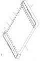
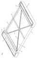
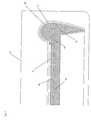
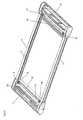
Figure 1 shows a perspective view of a first example of a display device constructed in accordance with an embodiment of the invention;Figure 2 shows a perspective view of the display device ofFigure 1 in compact form;Figure 3 shows a perspective view of the display device ofFigure 1 in an extended form with the screen removed for clarity;Figure 4 shows an enlarged detail ofFigure 3 shown from above;Figure 5 shows a partially sectioned enlarged detail ofFigure 3 shown in perspective;Figure 6 shows a cross-section of one of the side members of the first example interlocking with a side of the screen;Figure 7 shows a partial cross-section of the display device ofFigure 1 taken through the cross-bar;Figure 8 shows a perspective view of a second example of a display device constructed in accordance with an embodiment of the invention;Figures 9a, 9b and 9c show a perspective view of the display device ofFigure 8 in compact form;Figure 10 shows a perspective view of the display device ofFigure 8 in an extended form with the screen removed for clarity;Figure 11 shows an enlarged detail ofFigure 10 shown from above;Figure 12 shows a partially sectioned enlarged detail ofFigure 8 shown in perspective;Figure 13 shows a cross-section of one of the side members ofFigure 8 interlocking with a side of the screen; and,Figure 14 shows a partial cross-section of the display device ofFigure 8 taken through the cross-bar.- Referring to the drawings, a display device 1 comprises a
rollable screen 2 with twoopposed side members 3. Therollable screen 2 is rolled at each ends about one of two opposedparallel rollers 4. Eachroller 4 is mounted in ahousing 5 and is free to rotate about its axis. Anaperture 6 in the face of thehousing 5 allows thescreen 2 to pass into and out of thehousings 5. The arrangement of thehousings 5 androllers 4 at each end of thescreen 2 is identical in construction and operation and so only one will be described in detail in the following. This symmetric construction is an advantage of the preferred embodiment as it helps to keep down manufacturing costs. - Referring to
Figure 4 , a detailed view of part of thehousing 5 is shown. At each end of theroller 4 there is apin 7 which is co-aligned with the axis of theroller 4. Eachpin 7 is received by acomplementary recess 8 formed in thehousing 5 which holds theroller 4 in position whilst allowing it to rotate about its longitudinal axis. A pair of roll bar guides 9 are positioned adjacent to thehousing aperture 6, being positioned parallel to theroller 4, with oneroll bar guide 9 above the other to form a roll bar aperture between them which is narrower than thehousing aperture 6. This roll bar aperture acts as a guide for thescreen 2 as it moves back and forth through thehousing aperture 6. The roll bar guides 9 are retained at their ends bybrackets 11 formed in the interior of thehousing 5. Thebrackets 11 hold the roll bar guides 9 in position whilst allowing them to rotate about their axes. Hence, as well as guiding thescreen 2, the smooth and rotatable nature of the roll bar guides 9 reduce frictional wear and other stresses on thescreen 2 as it passes through thehousing 5. - Referring to
Figure 3 , a similar view toFigure 1 but with the screen removed for reason of clarity, an X-frame 12 is shown attached to the twoopposed housings 5. The X-frame 12 is positioned immediately under thescreen 2. In the embodiment shown theX frame 12 is comprised of two telescopicallyextendible members X-frame member housing 5 through thehousing aperture 6 and is attached to an interior surface of therespective housing 5 in such a way that allows it to pivot. The X-frame 12 provides further structural rigidity to the display device 1. The X-frame 12 can also be used to limit the maximum extension of thescreen 2. - One continuous,
extendible side member 3 is disposed at each side of thescreen 2. Each end of eachside member 3 is accommodated by arespective housing 5 which it enters through aguide aperture 24. As thescreen 2 extends or retracts from thehousing 5, theside members 3 also extend or retract from thehousing 5 to provide a continuous, structurally rigid edge to thescreen 2. This arrangement provides several advantages. - First, it provides added structural rigidity to the device 1 as a whole and to the
screen 2 in particular. This gives several beneficial capabilities to the device 1 when being used in its deployed mode. For example, the device 1 can be held in one hand, or in both hands, or placed on an uneven surface, whilst maintaining its form. Secondly, it provides support and stiffness to thescreen 2, allowing it to maintain its flatness. As well as providing the advantages of a flat display surface, this can also prevent damage to thescreen 2 where it is made of a technology susceptible to damage from sharp bending of its surface. Thirdly, the solid edge provides protection for the edge of thescreen 2 from damage from external sources, as well as giving the device 1 a solid, rigid look, which is substantially uniform regardless of the extended length of thescreen 2. - Similarly, an
extendible backing layer 32 can also be provided. This can be positioned beneath thescreen 2, extending between theside members 3, and in combination with theside members 3 would encase the parts of thescreen 2 other than the display surface itself. This would allow circuitry or other components positioned under the screen to be hidden from view and protected from damage. This would also provide a more aesthetically pleasing, solid appearance to the device 1, which makes the device 1 more appealing to consumers, and can increase further the rigidity of thescreen 2. - The
backing layer 32 may be in the form of plural parallel slats which each extend across the width of thescreen 2 and have increased rigidity by locking into the side member using, for example, a tongue and groove arrangement. (Such slats 35 are shown in the second example discussed below.) - Alternatively or additionally, the
backing layer 32 can be formed, in whole or in part, from a bistable or smart material (such as a shape memory alloy) that has some increased rigidity in the flat deployed configuration. Such a smart material can utilise a pseudo-elastic effect (which can be enhanced, for example, by passing a current through the layer) to increase flexibility or undergo a solid-state phase change as thescreen 2 rolls about therollers 4. - A cross-bar 16 is attached to the underside of the screen and runs across its width parallel to the
rollers 4. The two ends of thebar 16 are attached to the twoside members 3 respectively. As shown more clearly inFigure 7 , anend profile 31, which in the preferred embodiment has a shape corresponding to the cross-sectional shape of theside member 3 in its open extended form, is formed at each end of the cross-bar 16 to lock theside members 3 in their load bearing form. In the preferred embodiment the cross-bar 16 is positioned at the midpoint of thescreen 2 and the midpoint of the twoside members 3. The cross-bar 16 serves a number of purposes. First, it acts as an additional support for thescreen 2. Secondly, it provides a permanent connection between thescreen 2 and theside members 3 at their midpoints which has the effect of maintaining their correct relative alignment and holds the midpoints of theside members 3 in their load-bearing bistable form at all extensions between fully compact and fully extended.. Thirdly, it acts as a reference marking the midpoint of thescreen 2 which can be used when retracting the screen or extending it to the desired position. Optionally the cross-bar 16 and the X-frame 12 can be attached to each other at their midpoints to further aid this process. - In the preferred embodiment the
side members 3 are formed from a bistable material, such as are known per se. Bistable materials have the property of being able to take on two stable structural forms. Hence a member made using a bistable material is capable of forming two stable structures. Furthermore such a member can have one of its ends in a first stable state, and the other end in a second stable state, without significant instability. Bistable materials are also capable of forming members capable of bearing considerable loads. They are therefore well suited to theside members 3, as in a first stable state they can form an extended member capable of bearing load and providing support to the screen, and in a second stable state they can take on a more compact form which is stable. - Referring now to
Figures 5 and 6 , a cross section of abistable side member 3 and part of the rest of the device 1 is shown. In its extended form, eachside member 3 has a cross-sectioned shape that is approximately an inverted tear-drop, though with oneedge 22 slightly more inboard that theother edge 23. - In the preferred embodiment the
side members 3 lock to the edges of thescreen 2 as thescreen 2 is extended. Ascreen edge strip 17 is attached to each side of thescreen 2 and runs along the extent of its length. Eachscreen edge strip 17 has anupper groove 18 and alower groove 19 running along its length. When thescreen 2 is extended, theedges side members 3 locate into thelower groove 18 andupper groove 19 respectively of the respective screen edge strips 17. The combination of thescreen edge strip 17 with thebistable side members 3 "locked" into it provides a structurally rigid tubular member capable of bearing considerable load. This provides structural rigidity to the display device 1 as a whole, as well as supporting thescreen 2 and constraining its edges, providing resistance to deformation of the screen. - In the compact form, each
side member 3 is almost entirely in a relatively flat form. When in this form, the two legs of the lower V-shapedsection 26 close together, whilst the uppercurved section 27 flattens out so the section as a whole is substantially planar. Referring toFigure 4 , the end of theside member 3 which is accommodated within thehousing 5 takes on this relatively flat form and is accommodated bychannels 28 in the rear wall of thehousing 5. - In order to aid the transition of each
side member 3 between its two stable forms as it passes between the interior and exterior of thehousing 5, thechannel 28 stops short of theguide aperture 24 and theguide aperture 24 is shaped according to the two forms of the bistable material. Preferably, theguide aperture 24 has a shape intermediate the cross-sectioned shape of theside member 3 at its two stable forms. In other words, theguide aperture 24 is shaped to correspond to the shape of theside member 3 at its transition between the two stable forms. In a further embodiment, sprung bearings and/or roll-bars (not shown) can be positioned adjacent to thechannel 28 and guideaperture 24 and arranged to aid the transition. (An example of this arrangement is shown in the second example discussed below.) - Accordingly, as each
side member 3 is extended out of thehousing 5, it passes through atransition 29 at which the two legs of the lower V-section 26 spring apart and itsedge 23 is guided into position to lock intogroove 19 of thescreen edge strip 17, whilst the uppercurved section 27 curls over to allow itsedge 22 to lock into theupper groove 18 of thescreen edge strip 17. This provides a "zip-fastening" effect between eachside member 3 andscreen edge strip 17, theside members 3 andedge strip 17 "locking" together as theside members 3 extend through theirrespective guide apertures 24. - In an additional embodiment, in place of a bistable material, the
side members 3 can be formed from a material having a single intrinsic stable form, with a second stable form being achieved by the use of a magnetic strip. For example, the V-section 26 ofside member 3 can have a first stable form where its two legs spring apart, and a second stable form where its two legs are held together by the action of a magnet on one of the legs and exerting a magnetic attraction to a magnetic element on the other leg. The guide apertures 24 again aid the transition between the two stable forms. - It will be appreciated that the display device 1 is in principal capable of being deployed in any intermediate configuration between the fully retracted, compact form and its fully extended form if desired.
- Referring to
Figure 2 , the display device 1 is shown in its most compact form. Thescreen 2 is fully retracted and thehousings 5 have come together to abut each other. Thehousings 5 can be locked together in this state with a latch (not shown) to prevent the device 1 from extending unintentionally. Thescreen 2 is rolled about the tworollers 4, the cross-bar 16 is accommodated equally in two recesses in thehousings 5, the X-frame 12 has telescopically retracted, and theside members 3 have largely retracted into thehousing 5, having assumed their relatively flat form, and are accommodated in thechannels 28. - There are various options for deploying the device 1. For example, the
housings 5 could be manually separated until thescreen 2 achieved the desired width. Alternatively or additionally, one or bothrollers 4 could be motor driven to allow the device to automatically produce ascreen 2 of the desired width/length. Therollers 4 could be spring loaded to bias the device 1 to a pre-selected configuration. A brake (not shown), such as a friction pad bearing on one or bothside member 3 can be incorporated into one or both of thehousings 5 to allow thescreen 2 to be locked into position in either a closed or partially or fully deployed configuration. This brake may be manually or electrically operated for example. - It is possible for the display device 1 to be deployed in more than one configuration, allowing
screens 2 of different sizes and aspect ratios to be formed appropriate to the application for which the device 1 is being used. It is possible to completely automate the deployment of thescreen 2.Controls 30 on thehousing 5 may be used by the user to select an application that the device is to be utilised for (for example PDA or tablet mode). The device 1 could then automatically extend thescreen 2 to the appropriate size and then lock it in place. The degree of screen extension could be determined for example by measuring the amount of rotation of therollers 4 using electronic or optical means, such measuring techniques being known per se. - The
screen 2 itself can be made from an organic LED (OLED) or polymer liquid crystal technology. Thescreen 2 can be combined with other technologies such as a flexible circuit control membrane to drive the display, and/or a flexible ion-polymer battery for power supply, and/or electro-luminescent cable to back-light the display. Alternatively circuitry, batteries or other components can be stored inside therollers 4, or elsewhere in thehousing 5. - In addition, the
screen 2 can be used for input as well as display. A touch-sensitive screen 2 can be implemented by adding charge grid technology to thescreen 2. Sufficient support is given to thescreen 2 to provide a substantively solid surface, permitting touch-sensitive operation. The X-frame 12, cross-bar 16 and particularly theside members 3 all provide support to thescreen 2, whilst the "zip fastening" interface between theside members 3 and the screen edge strips 17 constrain the screen edges to provide a stiffening effect, further adding to its ability to resist deformation of its surface. In addition, ribs or slats (not shown) can be embedded in thescreen backing 32 running parallel to therollers 4. These would provide added stiffness to thescreen 2 in this direction, whilst not affecting the screen's ability to roll about therollers 4. Such ribs may have a cross sectional shape that is square or rectangular or some other shape, such as a sector of a circle. - The display device 1 can also be used with a
simpler screen 2, such as a static solid state screen combined with a magnetic print head/refresh bar in thehousing 5 which resets the image each time the device 1 is opened. This would allow applications such as digital newspapers, key documents or web site display. - The display device 1 can be combined with other technology to provide other applications. CPU and other processing means could be encased by the
housing 5. Communication devices can be encased in thehousing 5 to allow the device 1 to access and display web pages, for example. USB connectivity can be added to allow interfacing to other external devices. Input devices can be associated with thehousing 5. For example, pointing devices such as a tracker ball or mouse "nubbin" and/or hot keys can be provided in one of thehousings 5 at an ergonomically suitable position. - Referring now to
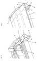
Figures 8 to 14 , a second example of an embodiment of the present invention is shown. Like reference numerals are used for corresponding features in the first example (shown inFigures 1 to 7 ) and the second example. The second example differs from the first example only in certain features and accordingly not all features of the second example will be discussed in detail here. Generally speaking the second example differs from the first embodiment in that thehousings 5 are more stylised, thechannels 28 are positioned in front of therollers 4 rather than in the rear wall of thehousings 5, and there is a different locking arrangement concerning theside members 3 and the screen edge strips 17, which allow among other things a reduced cross-section profile of theside members 3. Figure 8 shows the display device 1 in a deployed configuration with thelid 33 of eachhousing 5 removed for clarity. Thehousings 5 support therollers 4 which are attached to thescreen 2 andside members 3 which are attached to the screen edge strips 17. The screen edge strips 17 in this example form the top face of the side structure rather than the interior.Figure 9a shows the display device 1 in its collapsed configuration.Fig 9b shows the profile of thescreen 2 when fully stored and rolled around therollers 4.Figure 9c shows the device with thelids 33 attached to the housings. Thelids 33 preferably provide aviewing window 34 to allow the screen to be partially visible in the collapsed configuration.Figure 10 shows the display device 1 with thescreen 2 andhousing lids 33 not shown for clarity. The X-frame 12 is omitted in this example as the required structural rigidity is provided to the display unit 1 in particular by the combination of thehousings 5, theside members 3, the screen edge strips 17, and thescreen backing slats 35.- For each
housing 5, theaperture 6 is formed as a gap between thehousing 5 and thelid 33 when in place. Theroll bar guide 9 comprises two uppershort roll bars Figure 10 for onehousing 5 for clarity). The two uppershort roll bars aperture 6 adjacent to its top. The lowercogwheel roll bar 43 extends across the width of theaperture 6 adjacent to its bottom, and comprises of twocogwheels bar housing 5 such that it can rotate about its longitudinal axis. The roll bars 41, 42, 43 are arranged so that thescreen 5 passes between the upper roll bars 41, 42 and thelower roll bar 43 when passing through theaperture 6. - The
screen 5 hassupport slats 35 formed on its underside 32. Theslats 35 have a cross sectional shape in the form of a (partial) sector of a circle. This cross sectional shape allows theslats 35 to engage with the recesses formed between the teeth of the twocogs cogwheel roll bar 43. As eachslat 35 engages with thecogwheel roll bar 43 it is constrained in its alignment to be parallel to thecogwheel roll bar 43 and thereby perpendicular to the direction in which thescreen 2 is being extended or retracted. This arrangement helps maintain the screen in a rectangular/square form. - Referring now to
Figures 11 to 14 , detail sections of the display device 1 are shown, showing a part of onehousing 5,side member 3,screen edge strip 17, etc. Accordingly, in the following discussion in relation toFigures 11 to 14 , a single instance of these features is generally described. It should be noted, however, that the description applies equally to all instances of the particular feature. - Referring now to
Figure 11 (which shows an enlarged detail ofFigure 10 from above), thechannels 28 that store theside members 3 are positioned in front of theroller 4. This position, as opposed to positioning thechannels 28 behind theroller 4, has the advantage of reducing thetransition curvature 29 of the side-members 3 as they pass from their extended open V-shape form through theaperture 24 to their closed form, which makes extension and retraction easier. - The
screen edge strip 17 has twogrooves screen edge strip 17 comprises an underside surface sheet 38 (which may conveniently be formed of a metal), which is attached to the underside of thescreen edge strip 17, running along its length, and being positioned between the twogrooves grooves projections 37 is formed in theunderside surface sheet 38 on each opposed edge and runs along its length. Theprojections 37 overlap theunderside grooves underside surface sheet 38 may be biased in order to help retract and wind thescreen 3 about therollers 4. - Referring to
Figure 12 , eachside member 3 has an approximately V or Y or "wine glass" cross section shape when in its extended form. The end of each "leg" of theside member 3 has a series of apertures or recesses orperforations 39 running along its length which correspond to the series ofprojections 37 on thescreen edge strip 17. When extended, the ends of the two legs of eachside member 3 respectively fit into the twounderside grooves projections 37 are received by theperforations 39 in a reversible locking arrangement. When extended, thescreen edge strip 17 and the two legs of theside member 3 form a structurally rigid member with a generally triangular cross section shape which provides structural rigidity and protection to thescreen 3. When engaged with thescreen edge strip 17, the two legs of theside member 3 may have a slight inward bias which helps maintain the engagement of theprojections 37 with theperforations 39. The arrangement of theperforations 39 andprojections 37 has the advantage of providing a strong stable connection between theside member 3 and thescreen edge strip 17, and restricts any relative longitudinal movement between them. Theside member 3 locks to thescreen edge strip 17 from below only. This arrangement allows the top of thescreen 3 to be flat across its width with no structures extending above it. This arrangement also allows aside member 3 with a reduced cross sectional area, which in turn allows asmaller housing 5 to store it. - A guide member in the form of a
prong 36 is mounted in thehousings 5 between eachchannel 28 and guideaperture 24. Theprong 36 is positioned such that, as theside member 3 retracts into thehousing 5, the legs of theside member 3 are drawn past either side of theprong 36. The free end of theprong 36 is sized and shaped so as to slightly force apart the legs of theside member 3 as they pass over the end of theprong 36 such that theperforations 39 in the ends of the legs of theside members 3 disengage with theprojections 37 in thegrooves screen edge strip 17. Thescreen edge strip 17 passes above theprong 36 and is wound on theroller 4. Further inwards from its free end, theprong 36 curves upwards such that, once disengaged from theside member 3, thescreen edge strip 17 is lifted as it passes over theprong 36 such that thescreen edge strip 17 is no longer positioned between the legs of theside member 3. Theside member 3 is now unobstructed by thescreen edge strip 17 so that it can make the transition to a substantially planar form so that it can be stored in thechannel 28. - The
prong 36 performs similarly in reverse to engage theperforations 39 andprojections 37 when thescreen 5 is being extended. Figures 12, 13 and14 most clearly show (in cross-section) the side member passing through theaperture 24. Theside member 3 is preferably arranged with a cross section shape like a wine glass. It is not preferred to form theside member 3 from a bistable material in this example. It is preferred that theside member 3 is formed with a stable form that is intermediate between the open profile of its extended form (shown inFigures 12, 13 , and14 ) and a substantially planar profile. When theside member 3 is extended, thegrooves screen edge strip 17 hold theside member 3 in its extended form. When theside member 3 is retracted, thechannel 28 holds theside member 3 in its substantially planar form.- The
prong 36 may be provided with wheels or rollers, or a layer or coating of a low friction material, such as ptfe, at its free end. This reduces the friction between the end of theprong 36 and the legs of theside member 3 and/orscreen edge strip 17 as they slide over theprong 36. - As can be seen most clearly in
Figure 14 , theside member 3 has aflexible edge 40 at its base to provide a smooth edge. The flexiblescreen edge strip 17 has a shaped inward edge to support thescreen backing slats 35 forming the screen back 32. - Embodiments of the present invention have been described with particular reference to the examples illustrated. However, it will be appreciated that variations and modifications may be made to the examples described within the scope of the present invention.
Claims (20)
- A display device (1), the display device (1) comprising:an extendible screen (2) that is extendible in an extension direction from a relatively compact form to an extended form, the display device (1) having or being connectable to drive circuitry for driving the display of the screen (2), the screen (2) in the extended form having opposed edges that are substantially parallel to the extension direction; and,at least one of said opposed edges having an extendible side member (3),characterised in that the at least one opposed edge has the extendible side member (3) connected thereto, andin that the or each extendible side member (3) is extendible to provide support to and structural rigidity to the opposed edge of the screen (2) to which it is connected when the screen (2) is in the extended form.
- A display device (1) according to claim 1, comprising a respective extendible side member (3) for each of said opposed edges.
- A display device (1) according to claim 1 or claim 2, wherein the or at least one of the side members (3) is provided by a bistable material having a first stable state when said side member is extended and a second stable state when said side member is not extended.
- A display device (1) according to any of claims 1 to 3, wherein the screen (2) is extendible to and lockable at an intermediate position between said relatively compact form and said extended form, the or each side member (3) being extendible to provide support to and structural rigidity to the screen (2) when the screen (2) is in the intermediate position.
- A display device (1) according to any of claims 1 to 4, comprising a bar (16) extending between said opposed edges, the bar (1) being fixed to the screen (2) and the or each side member (3).
- A display device (1) according to claim 5, wherein said bar (16) has an end profile at at least one end which engages with a part of the corresponding side member (3) to hold that part of the side member (3) in its extended form.
- A display device (1) according to any of claims 1 to 6, comprising a locking mechanism for locking the or at least one of the side members (3) in its extended form.
- A display device (1) according to any of claims 1 to 7, comprising at least one housing (5) which at least partially accommodates the screen (2) when in said relatively compact form, wherein the or at least one of the side members (3) is at least partially accommodated by the housing (5) when the screen (2) is in said relatively compact form.
- A display device (1) according to claim 8, wherein the housing (5) has a guide aperture (24) through which said side member (3) passes on extension or retraction of the screen (2) in order to guide the movement of said side member (2) between the extended and retracted states of said side member (2).
- A display device (1) according to any of claims 1 to 9, wherein at least one of said opposed edges of the screen (2) has a groove (18) which receives a tongue (22) of the corresponding side member (3) when the screen (2) is in the extended form.
- A display device (1) according to claim 10, wherein the tongue (22) is provided by an edge of the side member (3).
- A display device (1) according to claim 8, wherein the side member (3) has a first cross-sectional shape when in its extended form and a second cross-sectional shape when in its retracted form, the housing (5) has a guide aperture (24) through which said side member (3) passes on extension or retraction of the screen (2), and said side member (3) has a tongue (22) provided by an edge of said side member (3) and the corresponding edge of said screen (2) has a corresponding groove (18), wherein said guide aperture (24) is arranged to guide the transition of said side member (3) between its first and second shapes on retraction and extension of the side member (3) respectively and to cause said tongue (22) to engage with said groove (18) on extension of the side member (3).
- A display device (1) according to any of claims 1 to 9, wherein at least one of said opposed edges of the screen (2) has plural projections (37) which are received by respective plural apertures (39) or recesses on the corresponding side member (3) when the screen (2) is in extended form to provide a reversible locking arrangement between said screen edge and said side member (3).
- A display device (1) according to claim 13, comprising at least one guide member (36) for at least one side member, the or each guide member (36) being arranged to guide the side member (3) and screen edge into or out of locking engagement on extension or retraction respectively of said side member (3) and screen (2).
- A display device (1) according to any of claims 1 to 14, wherein the screen (2) comprises a screen backing layer formed from a plurality of substantially parallel slats (35) arranged perpendicularly to the extension direction.
- A display device (1) according to any of claims 1 to 15, wherein the screen (2) comprises a screen backing layer formed from a bistable material that has increased rigidity when planar.
- A display device (1) according to any of claims 1 to 16, wherein the screen (2) comprises a screen backing layer formed from a smart material that has increased rigidity when planar and is capable of undergoing a current-assisted solid-state phase transition.
- A display device (1) according to any of claims 1 to 17, wherein the screen (2) is arranged to roll from the extended form to the relatively compact form.
- A display device (1) according to claim 18, wherein the rolling screen (2) rolls about a single axis.
- A display device (1) according to claim 18, wherein the rolling screen (2) rolls partly about a first axis and partly about a second parallel axis.
Applications Claiming Priority (2)
| Application Number | Priority Date | Filing Date | Title |
|---|---|---|---|
| US48084303P | 2003-06-23 | 2003-06-23 | |
| PCT/GB2004/002677WO2004114259A2 (en) | 2003-06-23 | 2004-06-22 | Display device having an extendible screen |
Publications (2)
| Publication Number | Publication Date |
|---|---|
| EP1642253A2 EP1642253A2 (en) | 2006-04-05 |
| EP1642253B1true EP1642253B1 (en) | 2012-10-03 |
Family
ID=33539326
Family Applications (1)
| Application Number | Title | Priority Date | Filing Date |
|---|---|---|---|
| EP04743028AExpired - LifetimeEP1642253B1 (en) | 2003-06-23 | 2004-06-22 | Display device having an extendible screen |
Country Status (4)
| Country | Link |
|---|---|
| US (2) | US7180665B2 (en) |
| EP (1) | EP1642253B1 (en) |
| GB (1) | GB2420905B (en) |
| WO (1) | WO2004114259A2 (en) |
Cited By (3)
| Publication number | Priority date | Publication date | Assignee | Title |
|---|---|---|---|---|
| CN110009998A (en)* | 2017-12-06 | 2019-07-12 | 乐金显示有限公司 | Flexible display apparatus |
| CN110035155A (en)* | 2019-04-19 | 2019-07-19 | Oppo(重庆)智能科技有限公司 | A kind of terminal device |
| EP3905021B1 (en)* | 2020-04-27 | 2025-06-25 | Lg Electronics Inc. | Mobile terminal and control method therefor |
Families Citing this family (132)
| Publication number | Priority date | Publication date | Assignee | Title |
|---|---|---|---|---|
| US20030048256A1 (en)* | 2001-09-07 | 2003-03-13 | Salmon Peter C. | Computing device with roll up components |
| EP1642253B1 (en)* | 2003-06-23 | 2012-10-03 | Simon Richard Daniel | Display device having an extendible screen |
| US20060038745A1 (en)* | 2004-08-19 | 2006-02-23 | Alex Naksen | Variable stiffness screen |
| US7667962B2 (en) | 2004-08-20 | 2010-02-23 | Mullen Jeffrey D | Wireless devices with flexible monitors and keyboards |
| US7818910B2 (en)* | 2004-09-29 | 2010-10-26 | The United States Of America As Represented By The Secretary Of The Army | Weapon integrated controller |
| US20060076899A1 (en)* | 2004-10-12 | 2006-04-13 | Israel Baumberg | Emergency lighting system |
| TWI259715B (en)* | 2005-01-25 | 2006-08-01 | Wistron Corp | Electronic device able to adjust the size of the display area |
| US7724508B2 (en)* | 2005-05-20 | 2010-05-25 | Polymer Vision Limited | Protective cover for flexible display screen |
| US7510111B2 (en)* | 2005-12-29 | 2009-03-31 | Dnp Denmark A/S | Front projection screen assembly |
| EP1970886B1 (en)* | 2006-01-06 | 2015-06-03 | Unified Innovative Technology, LLC | Mobile terminal device, display method, display program, and recording medium |
| US7612938B2 (en)* | 2006-02-14 | 2009-11-03 | Seiko Epson Corporation | Portable projection screen assembly |
| US7623290B2 (en)* | 2006-02-14 | 2009-11-24 | Seiko Epson Corporation | Portable screen assemblies for projectors |
| US7619814B2 (en)* | 2006-02-14 | 2009-11-17 | Seiko Epson Corporation | Portable projection screen assembly |
| TW200816436A (en)* | 2006-06-16 | 2008-04-01 | Polymer Vision Ltd | Varied pitch connection device and method |
| USD568364S1 (en)* | 2006-12-06 | 2008-05-06 | Samsung Electronics Co., Ltd. | Portable LCD screen |
| KR100842515B1 (en)* | 2006-12-21 | 2008-07-01 | 삼성전자주식회사 | Portable terminal with flexible display |
| US7787917B2 (en)* | 2006-12-28 | 2010-08-31 | Intel Corporation | Folding electronic device with continuous display |
| GB0702347D0 (en) | 2007-02-07 | 2007-03-21 | Plastic Logic Ltd | Electronic document reading devices |
| GB0702349D0 (en) | 2007-02-07 | 2007-03-21 | Plastic Logic Ltd | Electronic document readers and reading devices |
| GB0702350D0 (en) | 2007-02-07 | 2007-03-21 | Plastic Logic Ltd | Electronic reading devices |
| FR2912389B1 (en)* | 2007-02-09 | 2010-05-07 | Pascal Andre Brogard | HOME CINEMA INTEGRABLE PROJECTION ASCENSION SCREEN |
| JP2010526335A (en) | 2007-04-25 | 2010-07-29 | ポリマー、ビジョン、リミテッド | Electronic device with flexible display with edge protector |
| TWI413037B (en)* | 2007-06-15 | 2013-10-21 | Creator Technology Bv | Electronic device with a variable angulation of a flexible display |
| CN101330679A (en)* | 2007-06-22 | 2008-12-24 | 鸿富锦精密工业(深圳)有限公司 | Mobile phone and display control method thereof |
| GB2454032A (en) | 2007-10-24 | 2009-04-29 | Plastic Logic Ltd | Edgeless document viewer |
| USD596657S1 (en) | 2007-11-05 | 2009-07-21 | Bright View Technologies, Inc. | Portable front projection screen |
| JP2009116289A (en)* | 2007-11-06 | 2009-05-28 | Bright View Technologies Inc | Portable front projection screen |
| USD602973S1 (en)* | 2007-11-08 | 2009-10-27 | Bright View Technologies, Inc. | Portable front projection screen |
| CN101952873B (en) | 2007-11-21 | 2014-11-12 | 创造者科技有限公司 | An electronic device with a flexible display |
| WO2009067013A1 (en)* | 2007-11-23 | 2009-05-28 | Polymer Vision Limited | An electronic apparatus with improved functionality |
| GB2458106B (en) | 2008-03-03 | 2012-07-18 | Plastic Logic Ltd | Electronic document reader system |
| US7984746B2 (en)* | 2008-05-06 | 2011-07-26 | GM Global Technology Operations LLC | Cover deploying system utilizing active material actuation |
| WO2009144722A1 (en)* | 2008-05-27 | 2009-12-03 | Nir Dotan | Flexible flat screen display device |
| JP2010020270A (en)* | 2008-06-09 | 2010-01-28 | Seiko Epson Corp | Screen |
| JP2010019953A (en)* | 2008-07-09 | 2010-01-28 | Seiko Epson Corp | Screen |
| GB2468922A (en)* | 2009-03-27 | 2010-09-29 | Michael Korn | Retractable Screens |
| US8047254B2 (en)* | 2009-06-05 | 2011-11-01 | Bolton Iii Robert E | Magnetic cordless shade |
| KR101067587B1 (en)* | 2010-01-29 | 2011-09-27 | 주식회사 팬택 | Flexible terminal with shape conversion characteristics, shape conversion method and shape conversion device |
| EP2387212B1 (en) | 2010-05-10 | 2013-01-23 | Research In Motion Limited | Handheld electronic communication device having sliding display |
| US8412279B2 (en) | 2010-05-10 | 2013-04-02 | Research In Motion Limited | Handheld electronic communication device including touch-sensitive display |
| US8194399B2 (en) | 2010-07-16 | 2012-06-05 | Hewlett-Packard Development Company, L.P. | Altering the flexibility of a display device |
| JP2012053378A (en)* | 2010-09-03 | 2012-03-15 | Seiko Epson Corp | Screen device |
| KR101757927B1 (en)* | 2010-12-06 | 2017-07-17 | 엘지디스플레이 주식회사 | Window panel and method of fabricating of the same, touch screen panel and method of fabricating of the same |
| US8723890B2 (en) | 2010-12-23 | 2014-05-13 | Blackberry Limited | Handheld electronic device having sliding display and position configurable camera |
| US8532721B2 (en) | 2010-12-23 | 2013-09-10 | Blackberry Limited | Portable electronic device having sliding display providing event notification |
| US8514179B2 (en) | 2010-12-23 | 2013-08-20 | Research In Motion Limited | Handheld electronic communication device having an age compensating display |
| US8878746B2 (en)* | 2011-02-23 | 2014-11-04 | Corning Incorporated | Multi-screen electronic device with mechanism for transitioning between compact and expanded forms |
| CN102693683B (en)* | 2011-03-21 | 2014-01-22 | 纬创资通股份有限公司 | monitor |
| US9307061B2 (en)* | 2011-05-12 | 2016-04-05 | Nokia Technologies Oy | Flexible electronic apparatus |
| CN102542935A (en)* | 2011-11-28 | 2012-07-04 | 黄武昌 | Multi-functional double-cylinder type lamplight and remote recording display system |
| JP5783039B2 (en)* | 2011-12-28 | 2015-09-24 | 富士通株式会社 | Multi-divided housing coupling device and electronic device including the coupling device |
| US8724304B2 (en)* | 2012-04-20 | 2014-05-13 | Apple Inc. | Electronic devices with flexible displays having fastened bent edges |
| FR2990031B1 (en)* | 2012-04-27 | 2014-05-09 | Robert Miggiano | SCREEN PROJECTION SCREEN DEVICE |
| US8526109B1 (en) | 2012-06-29 | 2013-09-03 | Elite Screens Taiwan Co., Ltd. | Portable projection screen device |
| US9120290B2 (en)* | 2012-10-10 | 2015-09-01 | Universal Display Corporation | Flexible screen backed with rigid ribs |
| US8764255B2 (en) | 2012-10-10 | 2014-07-01 | Universal Display Corporation | Semi-rigid electronic device with a flexible display |
| KR102023015B1 (en)* | 2013-06-04 | 2019-09-19 | 엘지전자 주식회사 | Wall mounting type flexible display |
| CN103337222B (en)* | 2013-07-01 | 2015-07-08 | 京东方科技集团股份有限公司 | Flexible display device |
| US9389497B2 (en) | 2013-07-18 | 2016-07-12 | Tencent Technology (Shenzhen) Company Limited | Micro-projection-display devices and adjustable display screens |
| ITMI20131243A1 (en)* | 2013-07-24 | 2015-01-25 | Emmegi Sistemi Di Comunicazione S R L | SUPPORTING AND TENSIONING GROUP OF A FACILITATED SCREEN OF PROJECTION AND PROJECTION ASSEMBLY EMPLOYING THE SAME |
| US20150029229A1 (en)* | 2013-07-27 | 2015-01-29 | Sharp Laboratories Of America, Inc. | Adjustable Size Scrollable Display |
| TWI688850B (en) | 2013-08-13 | 2020-03-21 | 飛利斯有限公司 | Article with electronic display |
| CN105793781B (en) | 2013-08-27 | 2019-11-05 | 飞利斯有限公司 | Attachable device with deflection electronic component |
| WO2015031426A1 (en) | 2013-08-27 | 2015-03-05 | Polyera Corporation | Flexible display and detection of flex state |
| WO2015038684A1 (en) | 2013-09-10 | 2015-03-19 | Polyera Corporation | Attachable article with signaling, split display and messaging features |
| TWI608328B (en)* | 2013-10-24 | 2017-12-11 | 緯創資通股份有限公司 | Electronic device |
| JP6639400B2 (en) | 2013-12-24 | 2020-02-05 | フレックステラ, インコーポレイテッドFlexterra, Inc. | Support structure for attachable two-dimensional flexible electronic device |
| TWI676880B (en) | 2013-12-24 | 2019-11-11 | 美商飛利斯有限公司 | Dynamically flexible article |
| WO2015100224A1 (en) | 2013-12-24 | 2015-07-02 | Polyera Corporation | Flexible electronic display with user interface based on sensed movements |
| CN106030688B (en) | 2013-12-24 | 2020-01-24 | 飞利斯有限公司 | flexible electronics |
| KR102162566B1 (en)* | 2014-01-06 | 2020-10-08 | 삼성디스플레이 주식회사 | Portable apparatus including flexible display |
| US20150227245A1 (en) | 2014-02-10 | 2015-08-13 | Polyera Corporation | Attachable Device with Flexible Electronic Display Orientation Detection |
| USD761790S1 (en)* | 2014-02-13 | 2016-07-19 | Semiconductor Energy Laboratory Co., Ltd. | Portable information terminal |
| USD761788S1 (en)* | 2014-02-13 | 2016-07-19 | Semiconductor Energy Laboratory Co., Ltd. | Portable information terminal |
| USD761787S1 (en)* | 2014-02-13 | 2016-07-19 | Semiconductor Energy Laboratory Co., Ltd. | Portable information terminal |
| USD760219S1 (en)* | 2014-02-13 | 2016-06-28 | Semiconductor Energy Laboratory Co., Ltd. | Portable information terminal |
| USD761253S1 (en)* | 2014-02-13 | 2016-07-12 | Semiconductor Energy Laboratory Co., Ltd. | Portable information terminal |
| USD760218S1 (en)* | 2014-02-13 | 2016-06-28 | Semiconductor Energy Laboratory Co., Ltd. | Portable information terminal |
| USD761789S1 (en)* | 2014-02-13 | 2016-07-19 | Semiconductor Energy Laboratory Co., Ltd. | Portable information terminal |
| CN103941816A (en)* | 2014-03-28 | 2014-07-23 | 京东方科技集团股份有限公司 | Flexible display screen electronic device and control system thereof |
| EP2940552B1 (en)* | 2014-04-29 | 2020-04-22 | LG Display Co., Ltd. | Adjustable display device |
| JP3211128U (en)* | 2014-05-21 | 2017-06-29 | リム、ユソプ | Flexible display device having a roller that rotates by the action of an open operation force of a user |
| WO2015184045A2 (en) | 2014-05-28 | 2015-12-03 | Polyera Corporation | Device with flexible electronic components on multiple surfaces |
| KR101776262B1 (en) | 2014-06-27 | 2017-09-11 | 삼성전자주식회사 | Foldable device |
| US9791892B2 (en) | 2014-06-27 | 2017-10-17 | Samsung Electronics Co., Ltd. | Foldable device |
| JP6506648B2 (en)* | 2014-07-31 | 2019-04-24 | 株式会社半導体エネルギー研究所 | Display device |
| KR102273026B1 (en)* | 2014-08-28 | 2021-07-05 | 삼성전자주식회사 | Foldable electronic device |
| CN104407675B (en)* | 2014-12-12 | 2017-07-28 | 京东方科技集团股份有限公司 | Display screen reel system and its control method |
| WO2016101123A1 (en)* | 2014-12-23 | 2016-06-30 | 深圳市柔宇科技有限公司 | Flexible screen extension structure, flexible screen assembly, and terminal |
| WO2016138356A1 (en) | 2015-02-26 | 2016-09-01 | Polyera Corporation | Attachable device having a flexible electronic component |
| US9756744B2 (en)* | 2015-03-12 | 2017-09-05 | International Business Machines Corporation | Controlling rigidity of flexible displays |
| US9772657B2 (en)* | 2015-04-30 | 2017-09-26 | Samsung Electronics Co., Ltd. | Rollable display device |
| US10347160B2 (en)* | 2015-04-30 | 2019-07-09 | Samsung Electronics Co., Ltd. | Electronic apparatus having rollable display device |
| CN104933964B (en)* | 2015-07-03 | 2018-09-07 | 京东方科技集团股份有限公司 | Flexible display screen, display equipment and the display methods applied to flexible display screen |
| KR102148980B1 (en) | 2015-07-20 | 2020-08-28 | 삼성전자주식회사 | Electronic apparatus having a flexible display |
| US10020462B1 (en) | 2015-07-30 | 2018-07-10 | Apple Inc. | Electronic devices with flexible displays |
| US9625948B2 (en)* | 2015-08-24 | 2017-04-18 | Apple Inc. | Electronic devices with retractable displays |
| KR102464260B1 (en)* | 2015-10-02 | 2022-11-07 | 삼성전자주식회사 | Reconfigurable mobile device |
| DE202016101460U1 (en)* | 2016-03-16 | 2016-03-29 | Markus Kreuzer | Device for influencing the light during photo taking |
| KR102493385B1 (en)* | 2016-03-29 | 2023-01-30 | 삼성디스플레이 주식회사 | Display device |
| KR102426512B1 (en)* | 2016-06-09 | 2022-07-28 | 삼성디스플레이 주식회사 | Foldable display device |
| KR102493528B1 (en)* | 2016-08-11 | 2023-02-01 | 삼성디스플레이 주식회사 | Sliding display device |
| KR102591365B1 (en)* | 2016-09-12 | 2023-10-19 | 삼성디스플레이 주식회사 | Expandable display device |
| KR102630108B1 (en)* | 2016-10-04 | 2024-01-26 | 삼성디스플레이 주식회사 | Display device |
| KR102631840B1 (en)* | 2016-10-06 | 2024-01-31 | 삼성디스플레이 주식회사 | Expandable display device |
| KR102627801B1 (en)* | 2016-10-10 | 2024-01-22 | 삼성디스플레이 주식회사 | Expandable display device |
| KR20190071797A (en)* | 2016-11-02 | 2019-06-24 | 선전 로욜 테크놀로지스 컴퍼니 리미티드 | Support assembly, dial and smart bracelet |
| US10403184B2 (en) | 2016-12-22 | 2019-09-03 | Waldemar Veazie, IV | Freestanding exhibit display |
| WO2018120134A1 (en)* | 2016-12-30 | 2018-07-05 | 深圳天珑无线科技有限公司 | Retractable structure of flexible screen and mobile terminal |
| KR102501909B1 (en) | 2018-04-20 | 2023-02-20 | 엘지디스플레이 주식회사 | Display apparatus |
| KR102478444B1 (en)* | 2018-07-03 | 2022-12-15 | 엘지디스플레이 주식회사 | Display device |
| USD900761S1 (en)* | 2018-08-27 | 2020-11-03 | Lg Electronics Inc. | Portable monitor |
| EP3712875B1 (en)* | 2019-01-11 | 2023-09-13 | Jiangsu Kangrui New Material Technology Co., Ltd. | Structure of extending-type display screen |
| US12124298B2 (en)* | 2019-03-26 | 2024-10-22 | Lg Electronics Inc. | Rollable mobile terminal |
| KR102803889B1 (en)* | 2019-05-03 | 2025-05-08 | 삼성디스플레이 주식회사 | Display device |
| CN110166590A (en)* | 2019-05-06 | 2019-08-23 | 珠海格力电器股份有限公司 | Screen assembly, mobile phone and mobile device |
| CN110706600B (en)* | 2019-10-29 | 2021-12-03 | 武汉华星光电半导体显示技术有限公司 | Flexible display device |
| CN115004127B (en) | 2020-01-27 | 2024-07-16 | 华为技术有限公司 | Rolling display screen handheld structure with torsion spring |
| JP1714296S (en)* | 2020-02-19 | 2022-05-09 | Retractable television receiver | |
| US20230188630A1 (en)* | 2020-04-24 | 2023-06-15 | Lg Electronics Inc. | Mobile terminal |
| IT202000014365A1 (en)* | 2020-06-16 | 2021-12-16 | Nova Ferr S R L | Device for separating a volume of space |
| CN116171310A (en)* | 2020-07-14 | 2023-05-26 | 三星电子株式会社 | Electronic device including electronic component arrangement |
| US11860694B2 (en) | 2020-07-14 | 2024-01-02 | Samsung Electronics Co., Ltd. | Electronic device including rollable display |
| WO2022014908A1 (en) | 2020-07-14 | 2022-01-20 | 삼성전자 주식회사 | Electronic device comprising display support structure |
| EP4167046B1 (en) | 2020-07-14 | 2024-10-09 | Samsung Electronics Co., Ltd. | Electronic device including sensing structure |
| KR102292437B1 (en)* | 2020-08-21 | 2021-08-24 | 삼성전자주식회사 | Electronic apparatus having a flexible display |
| USD978226S1 (en)* | 2020-11-10 | 2023-02-14 | Emart International Inc | Collapsible screen |
| KR20220077429A (en)* | 2020-12-02 | 2022-06-09 | 엘지디스플레이 주식회사 | Display device |
| GB2602819B (en)* | 2021-01-15 | 2025-03-05 | Korn Wall Ltd | Screen System |
| GB2604123A (en)* | 2021-02-24 | 2022-08-31 | Korn Wall Ltd | Screen Structure |
| CN116888950A (en)* | 2021-03-22 | 2023-10-13 | 深圳传音控股股份有限公司 | Terminal, control method, and storage medium |
| CN115529776A (en)* | 2021-06-25 | 2022-12-27 | 北京小米移动软件有限公司 | A slide rail mechanism, telescopic screen structure and electronic equipment |
Family Cites Families (24)
| Publication number | Priority date | Publication date | Assignee | Title |
|---|---|---|---|---|
| USRE26156E (en)* | 1967-02-14 | Portable projection screen | ||
| US2404257A (en)* | 1940-03-16 | 1946-07-16 | Rossi Irving | Rollable window screen |
| US2350200A (en)* | 1943-06-11 | 1944-05-30 | Winfield J Starr | Screen holder |
| US2611427A (en)* | 1948-12-16 | 1952-09-23 | Da Lite Screen Company Inc | Portable picture screen |
| US2862552A (en)* | 1956-08-06 | 1958-12-02 | James N Franz | Collapsible projection screen |
| US4110003A (en)* | 1975-12-27 | 1978-08-29 | Knox Manufacturing Company | Portable movie screen device |
| US5373942A (en)* | 1984-05-22 | 1994-12-20 | Highland Supply Corporation | Spring strip wrapping and method for using same |
| US6256938B1 (en) | 1987-04-30 | 2001-07-10 | Rolatube Technology Limited | Elongate hollow element |
| JP3610077B2 (en) | 1992-03-26 | 2005-01-12 | セイコーエプソン株式会社 | Liquid crystal display device and electronic device |
| US6124851A (en) | 1995-07-20 | 2000-09-26 | E Ink Corporation | Electronic book with multiple page displays |
| GB9606200D0 (en) | 1996-03-25 | 1996-05-29 | Daton Lovett Andrew J | An extendible member |
| US5982537A (en)* | 1996-08-16 | 1999-11-09 | Sony Corporation | Speaker apparatus with a picture projecting screen |
| FI103238B1 (en) | 1997-02-21 | 1999-05-14 | Nokia Mobile Phones Ltd | Mobile communication devices |
| JP3385207B2 (en)* | 1997-09-05 | 2003-03-10 | 泉株式会社 | Portable screen |
| JPH11272205A (en) | 1998-03-19 | 1999-10-08 | Toshiba Corp | Display device |
| GB9812057D0 (en)* | 1998-06-04 | 1998-08-05 | Daton Lovett Andrew J | Means for extending the utility of extendible,coiled members |
| JP2000132122A (en) | 1998-10-28 | 2000-05-12 | Fuji Photo Film Co Ltd | Scroll-type display capable of continuous display |
| FI111998B (en) | 1999-12-08 | 2003-10-15 | Nokia Corp | User interface |
| WO2002033685A1 (en) | 2000-09-18 | 2002-04-25 | Peifang Zhu | Foldable display screen and its connection device |
| US20020090980A1 (en)* | 2000-12-05 | 2002-07-11 | Wilcox Russell J. | Displays for portable electronic apparatus |
| GB2370657A (en) | 2000-12-28 | 2002-07-03 | Constantinos Hadjisotiriou | Foldable flexible computer |
| DE20118593U1 (en)* | 2001-11-16 | 2002-05-23 | Jahn Hartmut | Multifunctional communication device |
| EP1642253B1 (en)* | 2003-06-23 | 2012-10-03 | Simon Richard Daniel | Display device having an extendible screen |
| US7510111B2 (en)* | 2005-12-29 | 2009-03-31 | Dnp Denmark A/S | Front projection screen assembly |
- 2004
- 2004-06-22EPEP04743028Apatent/EP1642253B1/ennot_activeExpired - Lifetime
- 2004-06-22WOPCT/GB2004/002677patent/WO2004114259A2/enactiveApplication Filing
- 2004-06-22GBGB0600794Apatent/GB2420905B/ennot_activeExpired - Lifetime
- 2004-06-22USUS10/873,561patent/US7180665B2/ennot_activeExpired - Lifetime
- 2007
- 2007-01-12USUS11/622,922patent/US7907337B2/enactiveActive
Cited By (4)
| Publication number | Priority date | Publication date | Assignee | Title |
|---|---|---|---|---|
| CN110009998A (en)* | 2017-12-06 | 2019-07-12 | 乐金显示有限公司 | Flexible display apparatus |
| CN110009998B (en)* | 2017-12-06 | 2021-03-23 | 乐金显示有限公司 | Flexible display device |
| CN110035155A (en)* | 2019-04-19 | 2019-07-19 | Oppo(重庆)智能科技有限公司 | A kind of terminal device |
| EP3905021B1 (en)* | 2020-04-27 | 2025-06-25 | Lg Electronics Inc. | Mobile terminal and control method therefor |
Also Published As
| Publication number | Publication date |
|---|---|
| WO2004114259A3 (en) | 2005-03-17 |
| US20050041012A1 (en) | 2005-02-24 |
| GB2420905B (en) | 2006-12-27 |
| WO2004114259A2 (en) | 2004-12-29 |
| US20070177404A1 (en) | 2007-08-02 |
| US7907337B2 (en) | 2011-03-15 |
| EP1642253A2 (en) | 2006-04-05 |
| GB0600794D0 (en) | 2006-02-22 |
| GB2420905A (en) | 2006-06-07 |
| US7180665B2 (en) | 2007-02-20 |
Similar Documents
| Publication | Publication Date | Title |
|---|---|---|
| EP1642253B1 (en) | Display device having an extendible screen | |
| JP7300190B2 (en) | Flexible display device for portable terminal | |
| US7440265B2 (en) | Variable-sized screen | |
| US11968791B2 (en) | Slidable display device | |
| EP2923352B1 (en) | Frame system for flexible panel | |
| US9983630B2 (en) | Electronic device with wrap around display | |
| CN105807850B (en) | Flexible display device | |
| US20130222998A1 (en) | Display device | |
| CN110728912B (en) | Flexible screen assembly and electronic equipment | |
| US20130021762A1 (en) | Flexible display with display support | |
| US20070211036A1 (en) | Roll-out touch screen support system (ROTS3) | |
| US20080204367A1 (en) | Wrap Display System Having A Flexible Display | |
| JP2023509032A (en) | Electronic device with rollable display | |
| CN208227090U (en) | Display device | |
| CN111933028A (en) | Display device | |
| WO2010041227A1 (en) | Flexible devices and related methods of use | |
| JP2020198605A (en) | Smartphone tablet | |
| US20220326735A1 (en) | Portable electronic device having rollable display structure | |
| US7268491B2 (en) | Expandable display having rollable material | |
| CN101453854A (en) | Electronic device structure with flexible screen | |
| US20070159780A1 (en) | Casing structure and function changing method thereof | |
| CN115394193A (en) | Supporting device, display device and electronic equipment | |
| CN110737310B (en) | Electronic equipment | |
| EP1795994B1 (en) | Handheld electronic device with reconfigurable keypad | |
| KR101021810B1 (en) | Sliding device and mobile device with same |
Legal Events
| Date | Code | Title | Description |
|---|---|---|---|
| PUAI | Public reference made under article 153(3) epc to a published international application that has entered the european phase | Free format text:ORIGINAL CODE: 0009012 | |
| 17P | Request for examination filed | Effective date:20060116 | |
| AK | Designated contracting states | Kind code of ref document:A2 Designated state(s):AT BE BG CH CY CZ DE DK EE ES FI FR GB GR HU IE IT LI LU MC NL PL PT RO SE SI SK TR | |
| DAX | Request for extension of the european patent (deleted) | ||
| 17Q | First examination report despatched | Effective date:20080421 | |
| GRAP | Despatch of communication of intention to grant a patent | Free format text:ORIGINAL CODE: EPIDOSNIGR1 | |
| RIN1 | Information on inventor provided before grant (corrected) | Inventor name:DANIEL, SIMON RICHARD Inventor name:VERITY WRIGHT, CHRISTOPHER | |
| GRAS | Grant fee paid | Free format text:ORIGINAL CODE: EPIDOSNIGR3 | |
| GRAA | (expected) grant | Free format text:ORIGINAL CODE: 0009210 | |
| AK | Designated contracting states | Kind code of ref document:B1 Designated state(s):AT BE BG CH CY CZ DE DK EE ES FI FR GB GR HU IE IT LI LU MC NL PL PT RO SE SI SK TR | |
| REG | Reference to a national code | Ref country code:GB Ref legal event code:FG4D | |
| REG | Reference to a national code | Ref country code:AT Ref legal event code:REF Ref document number:578289 Country of ref document:AT Kind code of ref document:T Effective date:20121015 Ref country code:CH Ref legal event code:EP | |
| REG | Reference to a national code | Ref country code:IE Ref legal event code:FG4D | |
| REG | Reference to a national code | Ref country code:DE Ref legal event code:R096 Ref document number:602004039543 Country of ref document:DE Effective date:20121206 | |
| REG | Reference to a national code | Ref country code:NL Ref legal event code:T3 | |
| REG | Reference to a national code | Ref country code:AT Ref legal event code:MK05 Ref document number:578289 Country of ref document:AT Kind code of ref document:T Effective date:20121003 | |
| PG25 | Lapsed in a contracting state [announced via postgrant information from national office to epo] | Ref country code:SI Free format text:LAPSE BECAUSE OF FAILURE TO SUBMIT A TRANSLATION OF THE DESCRIPTION OR TO PAY THE FEE WITHIN THE PRESCRIBED TIME-LIMIT Effective date:20121003 | |
| PG25 | Lapsed in a contracting state [announced via postgrant information from national office to epo] | Ref country code:FI Free format text:LAPSE BECAUSE OF FAILURE TO SUBMIT A TRANSLATION OF THE DESCRIPTION OR TO PAY THE FEE WITHIN THE PRESCRIBED TIME-LIMIT Effective date:20121003 Ref country code:SE Free format text:LAPSE BECAUSE OF FAILURE TO SUBMIT A TRANSLATION OF THE DESCRIPTION OR TO PAY THE FEE WITHIN THE PRESCRIBED TIME-LIMIT Effective date:20121003 Ref country code:ES Free format text:LAPSE BECAUSE OF FAILURE TO SUBMIT A TRANSLATION OF THE DESCRIPTION OR TO PAY THE FEE WITHIN THE PRESCRIBED TIME-LIMIT Effective date:20130114 | |
| PG25 | Lapsed in a contracting state [announced via postgrant information from national office to epo] | Ref country code:CY Free format text:LAPSE BECAUSE OF FAILURE TO SUBMIT A TRANSLATION OF THE DESCRIPTION OR TO PAY THE FEE WITHIN THE PRESCRIBED TIME-LIMIT Effective date:20121003 Ref country code:PT Free format text:LAPSE BECAUSE OF FAILURE TO SUBMIT A TRANSLATION OF THE DESCRIPTION OR TO PAY THE FEE WITHIN THE PRESCRIBED TIME-LIMIT Effective date:20130204 Ref country code:GR Free format text:LAPSE BECAUSE OF FAILURE TO SUBMIT A TRANSLATION OF THE DESCRIPTION OR TO PAY THE FEE WITHIN THE PRESCRIBED TIME-LIMIT Effective date:20130104 Ref country code:PL Free format text:LAPSE BECAUSE OF FAILURE TO SUBMIT A TRANSLATION OF THE DESCRIPTION OR TO PAY THE FEE WITHIN THE PRESCRIBED TIME-LIMIT Effective date:20121003 Ref country code:BE Free format text:LAPSE BECAUSE OF FAILURE TO SUBMIT A TRANSLATION OF THE DESCRIPTION OR TO PAY THE FEE WITHIN THE PRESCRIBED TIME-LIMIT Effective date:20121003 | |
| PG25 | Lapsed in a contracting state [announced via postgrant information from national office to epo] | Ref country code:AT Free format text:LAPSE BECAUSE OF FAILURE TO SUBMIT A TRANSLATION OF THE DESCRIPTION OR TO PAY THE FEE WITHIN THE PRESCRIBED TIME-LIMIT Effective date:20121003 | |
| PG25 | Lapsed in a contracting state [announced via postgrant information from national office to epo] | Ref country code:CZ Free format text:LAPSE BECAUSE OF FAILURE TO SUBMIT A TRANSLATION OF THE DESCRIPTION OR TO PAY THE FEE WITHIN THE PRESCRIBED TIME-LIMIT Effective date:20121003 Ref country code:DK Free format text:LAPSE BECAUSE OF FAILURE TO SUBMIT A TRANSLATION OF THE DESCRIPTION OR TO PAY THE FEE WITHIN THE PRESCRIBED TIME-LIMIT Effective date:20121003 Ref country code:EE Free format text:LAPSE BECAUSE OF FAILURE TO SUBMIT A TRANSLATION OF THE DESCRIPTION OR TO PAY THE FEE WITHIN THE PRESCRIBED TIME-LIMIT Effective date:20121003 Ref country code:BG Free format text:LAPSE BECAUSE OF FAILURE TO SUBMIT A TRANSLATION OF THE DESCRIPTION OR TO PAY THE FEE WITHIN THE PRESCRIBED TIME-LIMIT Effective date:20130103 Ref country code:SK Free format text:LAPSE BECAUSE OF FAILURE TO SUBMIT A TRANSLATION OF THE DESCRIPTION OR TO PAY THE FEE WITHIN THE PRESCRIBED TIME-LIMIT Effective date:20121003 | |
| PLBE | No opposition filed within time limit | Free format text:ORIGINAL CODE: 0009261 | |
| STAA | Information on the status of an ep patent application or granted ep patent | Free format text:STATUS: NO OPPOSITION FILED WITHIN TIME LIMIT | |
| PG25 | Lapsed in a contracting state [announced via postgrant information from national office to epo] | Ref country code:RO Free format text:LAPSE BECAUSE OF FAILURE TO SUBMIT A TRANSLATION OF THE DESCRIPTION OR TO PAY THE FEE WITHIN THE PRESCRIBED TIME-LIMIT Effective date:20121003 Ref country code:IT Free format text:LAPSE BECAUSE OF FAILURE TO SUBMIT A TRANSLATION OF THE DESCRIPTION OR TO PAY THE FEE WITHIN THE PRESCRIBED TIME-LIMIT Effective date:20121003 | |
| 26N | No opposition filed | Effective date:20130704 | |
| PGFP | Annual fee paid to national office [announced via postgrant information from national office to epo] | Ref country code:IE Payment date:20130908 Year of fee payment:10 | |
| REG | Reference to a national code | Ref country code:DE Ref legal event code:R097 Ref document number:602004039543 Country of ref document:DE Effective date:20130704 | |
| PG25 | Lapsed in a contracting state [announced via postgrant information from national office to epo] | Ref country code:MC Free format text:LAPSE BECAUSE OF FAILURE TO SUBMIT A TRANSLATION OF THE DESCRIPTION OR TO PAY THE FEE WITHIN THE PRESCRIBED TIME-LIMIT Effective date:20121003 | |
| REG | Reference to a national code | Ref country code:CH Ref legal event code:PL | |
| PG25 | Lapsed in a contracting state [announced via postgrant information from national office to epo] | Ref country code:LI Free format text:LAPSE BECAUSE OF NON-PAYMENT OF DUE FEES Effective date:20130630 Ref country code:CH Free format text:LAPSE BECAUSE OF NON-PAYMENT OF DUE FEES Effective date:20130630 | |
| PGFP | Annual fee paid to national office [announced via postgrant information from national office to epo] | Ref country code:DE Payment date:20140618 Year of fee payment:11 | |
| PGFP | Annual fee paid to national office [announced via postgrant information from national office to epo] | Ref country code:NL Payment date:20140626 Year of fee payment:11 | |
| PGFP | Annual fee paid to national office [announced via postgrant information from national office to epo] | Ref country code:FR Payment date:20140623 Year of fee payment:11 | |
| REG | Reference to a national code | Ref country code:IE Ref legal event code:MM4A | |
| PG25 | Lapsed in a contracting state [announced via postgrant information from national office to epo] | Ref country code:IE Free format text:LAPSE BECAUSE OF NON-PAYMENT OF DUE FEES Effective date:20140622 | |
| PG25 | Lapsed in a contracting state [announced via postgrant information from national office to epo] | Ref country code:TR Free format text:LAPSE BECAUSE OF FAILURE TO SUBMIT A TRANSLATION OF THE DESCRIPTION OR TO PAY THE FEE WITHIN THE PRESCRIBED TIME-LIMIT Effective date:20121003 | |
| PG25 | Lapsed in a contracting state [announced via postgrant information from national office to epo] | Ref country code:HU Free format text:LAPSE BECAUSE OF FAILURE TO SUBMIT A TRANSLATION OF THE DESCRIPTION OR TO PAY THE FEE WITHIN THE PRESCRIBED TIME-LIMIT; INVALID AB INITIO Effective date:20040622 Ref country code:LU Free format text:LAPSE BECAUSE OF NON-PAYMENT OF DUE FEES Effective date:20130622 | |
| REG | Reference to a national code | Ref country code:DE Ref legal event code:R119 Ref document number:602004039543 Country of ref document:DE | |
| REG | Reference to a national code | Ref country code:NL Ref legal event code:MM Effective date:20150701 | |
| REG | Reference to a national code | Ref country code:FR Ref legal event code:ST Effective date:20160229 | |
| PG25 | Lapsed in a contracting state [announced via postgrant information from national office to epo] | Ref country code:DE Free format text:LAPSE BECAUSE OF NON-PAYMENT OF DUE FEES Effective date:20160101 Ref country code:NL Free format text:LAPSE BECAUSE OF NON-PAYMENT OF DUE FEES Effective date:20150701 | |
| PG25 | Lapsed in a contracting state [announced via postgrant information from national office to epo] | Ref country code:FR Free format text:LAPSE BECAUSE OF NON-PAYMENT OF DUE FEES Effective date:20150630 | |
| PGFP | Annual fee paid to national office [announced via postgrant information from national office to epo] | Ref country code:GB Payment date:20230608 Year of fee payment:20 | |
| PG25 | Lapsed in a contracting state [announced via postgrant information from national office to epo] | Ref country code:GB Free format text:LAPSE BECAUSE OF EXPIRATION OF PROTECTION Effective date:20240621 | |
| REG | Reference to a national code | Ref country code:GB Ref legal event code:PE20 Expiry date:20240621 | |
| PG25 | Lapsed in a contracting state [announced via postgrant information from national office to epo] | Ref country code:GB Free format text:LAPSE BECAUSE OF EXPIRATION OF PROTECTION Effective date:20240621 |