EP1639955B1 - Driver tool for a spinal implant - Google Patents
Driver tool for a spinal implantDownload PDFInfo
- Publication number
- EP1639955B1 EP1639955B1EP05027645AEP05027645AEP1639955B1EP 1639955 B1EP1639955 B1EP 1639955B1EP 05027645 AEP05027645 AEP 05027645AEP 05027645 AEP05027645 AEP 05027645AEP 1639955 B1EP1639955 B1EP 1639955B1
- Authority
- EP
- European Patent Office
- Prior art keywords
- implant
- spinal
- nut member
- tool
- connecting rod
- Prior art date
- Legal status (The legal status is an assumption and is not a legal conclusion. Google has not performed a legal analysis and makes no representation as to the accuracy of the status listed.)
- Expired - Lifetime
Links
Images


Classifications
- A—HUMAN NECESSITIES
- A61—MEDICAL OR VETERINARY SCIENCE; HYGIENE
- A61F—FILTERS IMPLANTABLE INTO BLOOD VESSELS; PROSTHESES; DEVICES PROVIDING PATENCY TO, OR PREVENTING COLLAPSING OF, TUBULAR STRUCTURES OF THE BODY, e.g. STENTS; ORTHOPAEDIC, NURSING OR CONTRACEPTIVE DEVICES; FOMENTATION; TREATMENT OR PROTECTION OF EYES OR EARS; BANDAGES, DRESSINGS OR ABSORBENT PADS; FIRST-AID KITS
- A61F2/00—Filters implantable into blood vessels; Prostheses, i.e. artificial substitutes or replacements for parts of the body; Appliances for connecting them with the body; Devices providing patency to, or preventing collapsing of, tubular structures of the body, e.g. stents
- A61F2/02—Prostheses implantable into the body
- A61F2/30—Joints
- A61F2/44—Joints for the spine, e.g. vertebrae, spinal discs
- A—HUMAN NECESSITIES
- A61—MEDICAL OR VETERINARY SCIENCE; HYGIENE
- A61B—DIAGNOSIS; SURGERY; IDENTIFICATION
- A61B17/00—Surgical instruments, devices or methods
- A61B17/56—Surgical instruments or methods for treatment of bones or joints; Devices specially adapted therefor
- A61B17/58—Surgical instruments or methods for treatment of bones or joints; Devices specially adapted therefor for osteosynthesis, e.g. bone plates, screws or setting implements
- A61B17/68—Internal fixation devices, including fasteners and spinal fixators, even if a part thereof projects from the skin
- A61B17/70—Spinal positioners or stabilisers, e.g. stabilisers comprising fluid filler in an implant
- A61B17/7074—Tools specially adapted for spinal fixation operations other than for bone removal or filler handling
- A61B17/7091—Tools specially adapted for spinal fixation operations other than for bone removal or filler handling for applying, tightening or removing longitudinal element-to-bone anchor locking elements, e.g. caps, set screws, nuts or wedges
- A—HUMAN NECESSITIES
- A61—MEDICAL OR VETERINARY SCIENCE; HYGIENE
- A61B—DIAGNOSIS; SURGERY; IDENTIFICATION
- A61B17/00—Surgical instruments, devices or methods
- A61B17/56—Surgical instruments or methods for treatment of bones or joints; Devices specially adapted therefor
- A61B17/58—Surgical instruments or methods for treatment of bones or joints; Devices specially adapted therefor for osteosynthesis, e.g. bone plates, screws or setting implements
- A61B17/68—Internal fixation devices, including fasteners and spinal fixators, even if a part thereof projects from the skin
- A61B17/70—Spinal positioners or stabilisers, e.g. stabilisers comprising fluid filler in an implant
- A61B17/7001—Screws or hooks combined with longitudinal elements which do not contact vertebrae
- A61B17/7002—Longitudinal elements, e.g. rods
- A61B17/7004—Longitudinal elements, e.g. rods with a cross-section which varies along its length
- A61B17/7005—Parts of the longitudinal elements, e.g. their ends, being specially adapted to fit in the screw or hook heads
- A—HUMAN NECESSITIES
- A61—MEDICAL OR VETERINARY SCIENCE; HYGIENE
- A61B—DIAGNOSIS; SURGERY; IDENTIFICATION
- A61B17/00—Surgical instruments, devices or methods
- A61B17/56—Surgical instruments or methods for treatment of bones or joints; Devices specially adapted therefor
- A61B17/58—Surgical instruments or methods for treatment of bones or joints; Devices specially adapted therefor for osteosynthesis, e.g. bone plates, screws or setting implements
- A61B17/68—Internal fixation devices, including fasteners and spinal fixators, even if a part thereof projects from the skin
- A61B17/70—Spinal positioners or stabilisers, e.g. stabilisers comprising fluid filler in an implant
- A61B17/7001—Screws or hooks combined with longitudinal elements which do not contact vertebrae
- A61B17/7032—Screws or hooks with U-shaped head or back through which longitudinal rods pass
- A—HUMAN NECESSITIES
- A61—MEDICAL OR VETERINARY SCIENCE; HYGIENE
- A61B—DIAGNOSIS; SURGERY; IDENTIFICATION
- A61B17/00—Surgical instruments, devices or methods
- A61B17/56—Surgical instruments or methods for treatment of bones or joints; Devices specially adapted therefor
- A61B17/58—Surgical instruments or methods for treatment of bones or joints; Devices specially adapted therefor for osteosynthesis, e.g. bone plates, screws or setting implements
- A61B17/88—Osteosynthesis instruments; Methods or means for implanting or extracting internal or external fixation devices
- A61B17/90—Guides therefor
- A—HUMAN NECESSITIES
- A61—MEDICAL OR VETERINARY SCIENCE; HYGIENE
- A61B—DIAGNOSIS; SURGERY; IDENTIFICATION
- A61B17/00—Surgical instruments, devices or methods
- A61B17/56—Surgical instruments or methods for treatment of bones or joints; Devices specially adapted therefor
- A61B17/58—Surgical instruments or methods for treatment of bones or joints; Devices specially adapted therefor for osteosynthesis, e.g. bone plates, screws or setting implements
- A61B17/68—Internal fixation devices, including fasteners and spinal fixators, even if a part thereof projects from the skin
- A61B17/84—Fasteners therefor or fasteners being internal fixation devices
- A61B17/86—Pins or screws or threaded wires; nuts therefor
- A61B17/864—Pins or screws or threaded wires; nuts therefor hollow, e.g. with socket or cannulated
Definitions
- the present inventionrelates to spinal implants for osteosynthesis devices and, more particularly, to a set of devices comprising a driver tool and a nut member as set forth in the preamble of claim 1.
- a set of devicesis known from US 5,904,683 .
- U.S. Patent NO. 5,154,719One of such implants is disclosed in U.S. Patent NO. 5,154,719 .
- This deviceincludes a head portion having a pair of upright branches which are internally threaded and which has a U-shaped recess, and a screw portion projecting from the head portion.
- a connecting rodis received in the two branches, which are fixed in place by means of a ring member.
- the screw portionis composed of a solid material and the screw portion is merely anchored in the vertebral body. Accordingly, after the spinal implant penetrates in the vertebral body, fixation of the spinal implant is unstable and is liable to be undesirably affected with external forces when they are applied to the spinal implants.
- U.S. Patent NO. 5,879,351discloses a spinal osteosynthesis device comprising at least one vertebral rod, pedicle screws and deformable connectors.
- each of the pedicle screwsis composed of the same solid material as in the prior art discussed above, and a difficulty is similarly encountered in reliably fixing the pedicle screw in the vertebral body.
- each of the deformable connectorshas an oblong opening through which a head portion of the screw extends and each connector is resiliently supported between a cylindrical base and a nut, with a given space being provided for permitting relative movement of the vertebral rod.
- the spinal implantis caused to have a large number of component parts, resulting in a complicated structure and an increased cost.
- an outer periphery of the plughas a hexagonal profile, and a driver tool having a hexagonal groove is brought into engagement with the outer hexagonal wall of the plug for rotating the plug.
- the driver toolsince the driver tool has an outer diameter larger than that of the plug, increasing an occupying space for rotating the driver tool.
- the outer periphery of the driver toolis liable to interfere with the adjacent plug of the spinal implant, causing difficulties in rotating operation of the driver tool.
- Prior art US 6,039,738discloses a fastener, which is provided for use in retaining vertebrae in a desired spatial relationship.
- the present inventionhas been made with a view to overcoming the various disadvantages encountered in prior art devices and it is therefore an object of the present invention to provide a set of devices comprising a driver tool for rotating a spinal implant, and a nut member.
- a set of devicescomprising driver tool for a spinal implant having an implant body and an anchoring screw portion, and a nut member screwed onto a head portion of the implant body and having an upper wall formed with a tool engagement groove as defined in claim 1.
- a spinal osteosynthesis devicegenerally designated at 10, is shown as applied to separate vertebral bodies 12 for interconnecting plural vertebral bodies 12 in place.
- the spinal osteosynthesis device 10includes an elongated vertebral connecting rod 14 retained by a pair of spinal implants 16 of a first embodiment.
- Each of the spinal implants 16penetrates each vertebral body 12 in a manner as will be discussed below in detail.
- the connecting rod 14is made of malleable, elastically deformable material having a large elastic capacity, permitting elastic deformation necessary for adaptation it to differences in alignment, angulation and depth of penetration of the implants 16.
- the spinal implant 16includes a cylindrical implant body 18 for firmly retaining the connecting rod 14 in place, and an anchoring screw section 20 that longitudinally extends from the implant body 18 and adapted to be anchored in the vertebral body 12 (see FIGS. 1 and 2 ).
- the anchoring screw section 20has a hollow internal fusion chamber 22, and a plurality of spinal openings 24 each of which is composed of a longitudinally extending elongated slit. Each of the elongated slit 24 transversely extends through the anchoring screw section 20 from one side to the other side and communicates with the internal fusion chamber 22 to permit borne ingrowth into the fusion chamber 22.
- the anchoring screw section 20has a plurality of circumferentially spaced, elongated wall segments 26 defined between the hollow internal fusion chamber 22 and the plural slits 24, providing elastic deformation to the anchoring screw section 20 to allow adaptation of any positioning of the threaded section while permitting an effective fixation without impairing the borne anchorage.
- a head portion of the implant body 18is formed with a U-shaped rod retaining recess 28 that opens outward, and an internally threaded bore 30 extending in a longitudinal direction at a position adjacent the rod retaining recess 28.
- a disc shaped nut member 32is screwed into the internally threaded bore 30, thereby retaining the connecting rod 14 in place in the rod retaining recess 28.
- a bottom wall 34 of the retaining recess 28includes a rod movement stabilizing means 35 composed of slanted engagement surfaces 36 directly located in the rod retaining recess 28 for allowing pivotal movement of the connecting rod 14 in the retaining recess 28, thereby preserving mobility to the connecting rod 14.
- each of the slanted engagement surface 36is slightly inclined from points slightly displaced from the center of axis of the implant body 18 at an angle ⁇ from an axis of the connecting rod 14 perpendicular to the axis of the implant body 18.
- the connecting rod 14is allowed for pivotal movement within a range defined by the slanted engagement surfaces 36 of the retaining recess 28 of the implant body 18.
- the slanted engagement surfaces 36 of the rod movement stabilizing means 35is defined in the retaining recess 28 of the implant body 18, allowing the connecting rod 14 to be inclined.
- the connecting rod 14is inclined in a plane involving the center of axis of the implant body 18, the slanted engagement surface 36 of the rod movement stabilizing means 35 may be modified such that the connecting rod 14 is allowed to be slightly inclined in a plane crossing the central axis of the implant body 18. More particularly, as shown by a phantom line in FIG. 6 , the retaining recess 28 has inclined engagement surfaces 40 formed in a longitudinal direction in right and left directions in FIG. 6 , except for the threaded portion 38.
- the plural spinal implants 16are screwed into and anchored in separate vertebral bodies 12 in a manner as shown in FIGS. 1 and 2 such that the associated rod retaining sections 28 of two implant bodies 18 are aligned, and both ends of the connecting rod 14 are received in the implant bodies 18.
- the nut member 32are screwed into the threaded portions 30 of the implant bodies 18, respectively, firmly retaining the both ends of the connecting rod 14 to clamp the same in the required position.
- the anchoring screw section 20is allowed to be penetrated into the vertebral body 12 in reduced diametrical size owing to the inward elastic deformation of the separate elongated segments 26, thereby providing ease of penetration of the implant 16. Since, also, when the penetration of the anchoring screw section 20 has been completed, the separate elongated wall segments 26 expand to their original position due to their restoring forces, thereby providing an improved fixation, in an early stage, of the screw section 20 to the vertebral body 12 in a highly reliable manner. Owing to the provision of the plurality of spinal openings defined by the elongated slits 24 and the hollow internal fusion chamber 22, further, the spinal implant 16 permits borne ingrowth into the hollow fusion chamber 22 for thereby further improving fixation of the implant.
- both ends of the connecting rod 14are fitted to the retaining recesses 28 of the implant bodies 18 after the plural spinal implants 16 are firmly fitted to the vertebral bodies 12 in a manner discussed above, if the rotational positions of the retaining recesses 28 of the plural spinal implants 16 are not aligned with one another, a desired one of the spinal implants 16 may be slightly rotated.
- the connecting rod 14is partly allowed to be suitably deformed along the slanted surface 36, absorbing a slight difference in height of the bottom walls of the plural spinal implants 16 penetrated in the vertebral bodies 12.
- the connecting rod 14is reliably adaptable to that difference, providing improved engagement of the connecting rod in the plural spinal implants in an easy and simplified manner.
- FIG. 7shows a second embodiment of a spinal implant , with like parts bearing the same reference numerals as those used in FIGS. 1 to 5 .
- the spinal implant 16 of FIG. 7differs in structure from the first embodiment of the spinal implant in that the implant body 18 has a rod retaining recess 40 composed of a longitudinally extending oblong opening and a distal end of the implant body 18 has a laterally extending tool engagement groove 42.
- the spinal implant 16 of the second embodimenthas the same advantages as those of the first embodiment discussed above.
- Other features of the second embodiment of the spinal implant 16are identical to those of the first embodiment and, accordingly, a detailed description of the second embodiment of the spinal implant 16 is herein omitted for the sake of simplicity.
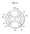
- FIGS. 8 to 11show a third embodiment of a spinal implant, which is a preferred embodiment of the present invention.
- the spinal implant 16includes an implant body 18 and an anchoring screw section 20 having a plurality of small apertures 46 extending in a plane perpendicular to the axis of the screw portion 20 to allow borne ingrowth therein.
- the implant body 18has an upper end formed with an outer thread 50, to which a nut member 52 having an upper wall formed with tool engagement grooves 56 is screwed.
- the implant body 18also has a U-shaped retaining recess 54, with which a spherical engaging segment 14a of a connecting rod 14 engages for pivotal movement.
- the implant body 18has a pair of upright retaining segments 18A, 18B providing relatively large spaces 62 and each having an arch-shaped cross section.
- the upright retaining segments 18A, 18Bprovide an open distal end such that when the spherical engaging segment 14A is retained in the U-shaped recess 54, the connecting rod 14 is allowed for pivotal movement relative to the central axis of the spinal implant 16.
- the nut member 52has a ring-shape having an inner thread engaging the outer thread 50 of the implant body 18.
- An upper side of the nut member 52has a plurality of tool engagement grooves 56 that cross each other in lateral direction.
- the ring-shape nut member 52receives therein a central pivot shaft 58 coaxially extending through the nut member 52.
- a lower ends of the central pivot shaft 58is integrally formed with a rod retaining member 60, that includes a central, globular retaining groove 60a, and a pair of laterally extending arch-shaped retaining grooves 60b.
- the rod retaining member 60projects downward from a lower distal end of the nut member 52.
- the rod retaining member 60has a radial length substantially equal to the diameter of the nut member 52 and has a lateral width slightly smaller than the width of the rod retaining groove 54.
- An upper end of the central pivot shaft 58has a circular flange 58a having substantially the same shape as the rod retaining member 60.
- FIGS. 8 and 12there is shown a fourth embodiment which is a preferred inventive embodiment of a driver tool 70 for rotating the nut member 52.
- the driver tool 70includes a hollow, tubular tool end 72 and an elongated shaft 74 extending upward from the tubular body 72.
- a lower end of the tubular bodyhas a plurality of substantially axially extending engaging segments 72a that are adapted to engage with the tool engagement grooves 56 formed on the upper wall of the nut member 52.
- the tubular body 72is designed to have a diameter substantially equal to the nut member 52.
- the anchoring screw sections 20 of the plural spinal implants 16penetrates the vertebral bodies and, subsequently, the connecting rod 14 and the spherical engaging segment 14a are located in the rod retaining groove 54 of the implant body 18.
- the rod retaining member 60is brought into engagement with the rod retaining groove 54 of the implant body 18, and the nut member 52 is screwed into the outer thread 50 of the implant body 18.
- the nut member 52is rotated with the driver tool 70 of which engaging teeth 72a meshes with the tool engagement grooves 56 of the nut member 52, such that the nut member 52 is fixed in place. This movement is enhanced with the aid of the driver tool 70, providing ease of fixing operation of the nut member 52 to the implant body 18.
- the tool engagement grooves 56may not be limited to the specific groove shown in FIGS. 8 and 9 , but may have any other configuration such as a bore.
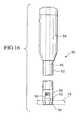
- FIGS. 13 to 16show a fifth embodiment of a driver tool , with the spinal implant 16 being identical in structure with that of the first embodiment except that the retaining plug 32 has a non-circular, hexagonal engagement groove 32A.
- an upper end of a driver tool 78has a grip section 78a, and a lower portion formed with a tool end 78b that has a hexagonal, nut engagement tip 78c.
- the driver tool 78is used in combination with a nut guide 80 that includes a grip section 84 and a hollow, cylindrical shaft 82.
- the grip section 84has an inner guide bore 84a that is adapted to receive the grip section 78a of the driver tool 78.
- the cylindrical shaft 82has an axially extending through-bore 86 to guide the driver tool 78.
- a lower end of the cylindrical shaft 82has an inner threaded bore 88, a nut guide chamber 90, an engaging guide chamber 92, and a rod engaging recess 94 that is adapted to receive the connecting rod 14.
- Plural preliminary mounting stems 98are fixedly connected to a mounting base 96 for temporarily supporting respective nut members 32 on top ends of the stems.
- the nut members 32have the hexagonal engagement grooves 32a, respectively.
- the plural spinal implants 16are sequentially fixed into the vertebral bodies 12, and the connecting rod 14 is suitably located in the rod retaining recesses 28 of the implant 16.
- the nut guide 80is placed on one of the nut members 32,which has been placed on the mounting stem 98, such that the nut member 32 is guided through the nut guide hole 90 of the nut guide 80.
- the nut member 32is thud held with the nut guide 80, and the nut guide 80 is moved to an operating position shown in FIG. 13 .
- the rod engaging recess 94 of the nut guide 80is aligned with the connecting rod 14 such that the upper portion of the implant body 18 engages with the engaging guide bore 92 of the nut guide 80 in a manner as shown in FIG. 13 .
- the driver tool 78is inserted through the nut guide 80 until the engagement tip 78c engages with the tool engagement groove 32a of the nut member 32, and the driver tool 78 is rotated to cause the nut member 32 to be screwed into the implant body 18 of the spinal implant 16 until the nut member 32 is brought into contact with the connecting rod 14. Accordingly, the nut member 32 is easily secured to the implant body 18 in a highly reliable manner without causing any misalignments or difficulties.
- driver tool and the nut member of the present inventionprovide numerous advantages over the prior art practices as is described under (D) and (E) below.
- (A) to (C) and (F)describe advantages of the useful background art.
- the anchoring screw section of the spinal implantincludes a spinal opening composed of an elongated slip or plural laterally extending bores
- the spinal openingmay have any other suitable configurations such as an oblong opening or an elliptical bore.
Landscapes
- Health & Medical Sciences (AREA)
- Orthopedic Medicine & Surgery (AREA)
- Neurology (AREA)
- Life Sciences & Earth Sciences (AREA)
- Surgery (AREA)
- Engineering & Computer Science (AREA)
- Biomedical Technology (AREA)
- General Health & Medical Sciences (AREA)
- Veterinary Medicine (AREA)
- Heart & Thoracic Surgery (AREA)
- Public Health (AREA)
- Animal Behavior & Ethology (AREA)
- Molecular Biology (AREA)
- Medical Informatics (AREA)
- Nuclear Medicine, Radiotherapy & Molecular Imaging (AREA)
- Cardiology (AREA)
- Oral & Maxillofacial Surgery (AREA)
- Transplantation (AREA)
- Vascular Medicine (AREA)
- Surgical Instruments (AREA)
- Prostheses (AREA)
Description
- The present invention relates to spinal implants for osteosynthesis devices and, more particularly, to a set of devices comprising a driver tool and a nut member as set forth in the preamble of
claim 1. Such a set of devices is known fromUS 5,904,683 . - In recent years, various research and development have been attempted to provide a spinal implant that is designed to achieve adaptation to differences in alignment, augulation and depth of penetration of adjacent spinal implants anchored to vertebral bodies which are spaced from one another.
- One of such implants is disclosed in
U.S. Patent NO. 5,154,719 . This device includes a head portion having a pair of upright branches which are internally threaded and which has a U-shaped recess, and a screw portion projecting from the head portion. A connecting rod is received in the two branches, which are fixed in place by means of a ring member. During this operating step, there exist some difficulties in precisely adjusting the orientation of the U-shaped recesses of the spaced spinal implants anchored in vertebral bodies, angulation of the spinal implants and depth of the spinal implants, with a resultant undesirable fixation of the implants and the connecting rod. Since, further, the screw portion is composed of a solid material and the screw portion is merely anchored in the vertebral body. Accordingly, after the spinal implant penetrates in the vertebral body, fixation of the spinal implant is unstable and is liable to be undesirably affected with external forces when they are applied to the spinal implants. U.S. Patent NO. 5,879,351 discloses a spinal osteosynthesis device comprising at least one vertebral rod, pedicle screws and deformable connectors. In this prior art, each of the pedicle screws is composed of the same solid material as in the prior art discussed above, and a difficulty is similarly encountered in reliably fixing the pedicle screw in the vertebral body. Further, each of the deformable connectors has an oblong opening through which a head portion of the screw extends and each connector is resiliently supported between a cylindrical base and a nut, with a given space being provided for permitting relative movement of the vertebral rod. With such a structure, the spinal implant is caused to have a large number of component parts, resulting in a complicated structure and an increased cost.- In known techniques, it has been a usual practice to lock a plug into the spinal implant by means of a tool holder. In practice, there are two types of head section formed with two upright branches, that is, a first type of head section having an internally formed thread, and a second type of head section having an outwardly formed thread. In the first type, the plug is screwed in the internal thread of the head section. In this event, the two branches are loosened, thereby providing a difficulty in tightly locking the connecting rod in the spinal implant. On the contrary, in the second type, the plug is screwed onto the outer thread of the head section. In this event, an outer periphery of the plug has a hexagonal profile, and a driver tool having a hexagonal groove is brought into engagement with the outer hexagonal wall of the plug for rotating the plug. In this event, since the driver tool has an outer diameter larger than that of the plug, increasing an occupying space for rotating the driver tool. Under these conditions, when two spinal implants are anchored in adjacent vertebral bodies in a relationship closer to one another, the outer periphery of the driver tool is liable to interfere with the adjacent plug of the spinal implant, causing difficulties in rotating operation of the driver tool.
- From
US 4,269,088 a power tool for rotating one of a plurality of nuts threadedly connected to studs is known. - From
WO 97/37605 - Prior art
US 6,039,738 discloses a fastener, which is provided for use in retaining vertebrae in a desired spatial relationship. - The present invention has been made with a view to overcoming the various disadvantages encountered in prior art devices and it is therefore an object of the present invention to provide a set of devices comprising a driver tool for rotating a spinal implant, and a nut member.
- According to the present invention, the above object is solved by a set of devices comprising driver tool for a spinal implant having an implant body and an anchoring screw portion, and a nut member screwed onto a head portion of the implant body and having an upper wall formed with a tool engagement groove as defined in
claim 1. - Other aspect and advantages of the invention will become more apparent from the following description, taken in conjunction with the accompanying drawings, illustrating by way of example the principles of the invention.
- In the following detailed description the embodiments according to
Figures 8 to 12 relate to the present invention, whereas the remaining embodiments are background art useful in order to understand the present invention. FIG. 1 is a schematic view of an osteosynthesis device incorporating a first preferred embodiment of a spinal implant, with a connecting rod being utilized to interconnect spaced vertebral bodies by means of plural spinal implants;FIG. 2 is a side view illustrating the relationship between the plural spinal implants and the associated connecting rod;FIG. 3 is an enlarged front view of the first preferred embodiment of the spinal implant;FIG. 4 is a cross sectional view of the spinal implant shown inFIG. 3 ;FIG. 5 is another cross sectional view of the spinal implant shown inFIG. 3 ;FIG. 6 is a left side view of the spinal implant shown inFIG. 3 ;FIG. 7 is an enlarged front view of a second preferred embodiment of a spinal implant;FIG. 8 is an enlarged front view of a third preferred embodiment of a spinal implant according to the present invention, with the connecting rod being shown as being fastened by the spinal implant of the third preferred embodiment;FIG. 9 is en enlarged, front view of a nut member in accordance with the invention forming part of the spinal implant shown inFIG. 8 ;FIG. 10 is an enlarged, plan view of the nut member shown inFIG. 8 ;FIG. 11 is an enlarged, bottom view of the nut member shown inFIG. 8 ;FIG. 12 is an enlarged, front view of a driver tool in accordance with the invention specifically suited for use in the nut member shown inFIG. 8 ;FIG. 13 is an enlarged view for illustrating the relationship between the spinal implant and a nut guide of a fourth preferred embodiment;FIG. 14 is a side view of the osteosynthesis device shown inFIG. 13 ;FIG. 15 is an enlarged, exploded view of the nut guide shown inFIG. 13 ; andFIG. 16 is an enlarged side view of the nut guide shown inFIG. 13 .- Referring to the drawings and more particularly to
FIGS. 1 and2 , a spinal osteosynthesis device, generally designated at 10, is shown as applied to separatevertebral bodies 12 for interconnecting pluralvertebral bodies 12 in place. - The
spinal osteosynthesis device 10 includes an elongated vertebral connectingrod 14 retained by a pair ofspinal implants 16 of a first embodiment. Each of thespinal implants 16 penetrates eachvertebral body 12 in a manner as will be discussed below in detail. The connectingrod 14 is made of malleable, elastically deformable material having a large elastic capacity, permitting elastic deformation necessary for adaptation it to differences in alignment, angulation and depth of penetration of theimplants 16. - Referring now to
FIGS. 3 and 4 , thespinal implant 16 includes acylindrical implant body 18 for firmly retaining the connectingrod 14 in place, and ananchoring screw section 20 that longitudinally extends from theimplant body 18 and adapted to be anchored in the vertebral body 12 (seeFIGS. 1 and2 ). - The anchoring
screw section 20 has a hollowinternal fusion chamber 22, and a plurality ofspinal openings 24 each of which is composed of a longitudinally extending elongated slit. Each of theelongated slit 24 transversely extends through the anchoringscrew section 20 from one side to the other side and communicates with theinternal fusion chamber 22 to permit borne ingrowth into thefusion chamber 22. Thus, the anchoringscrew section 20 has a plurality of circumferentially spaced,elongated wall segments 26 defined between the hollowinternal fusion chamber 22 and theplural slits 24, providing elastic deformation to theanchoring screw section 20 to allow adaptation of any positioning of the threaded section while permitting an effective fixation without impairing the borne anchorage. - A head portion of the
implant body 18 is formed with a U-shapedrod retaining recess 28 that opens outward, and an internally threadedbore 30 extending in a longitudinal direction at a position adjacent therod retaining recess 28. A disc shapednut member 32 is screwed into the internally threadedbore 30, thereby retaining the connectingrod 14 in place in therod retaining recess 28. - As seen in
FIGS. 5 and 6 , abottom wall 34 of theretaining recess 28 includes a rodmovement stabilizing means 35 composed ofslanted engagement surfaces 36 directly located in therod retaining recess 28 for allowing pivotal movement of the connectingrod 14 in theretaining recess 28, thereby preserving mobility to the connectingrod 14. To this end, each of theslanted engagement surface 36 is slightly inclined from points slightly displaced from the center of axis of theimplant body 18 at an angle Θ from an axis of the connectingrod 14 perpendicular to the axis of theimplant body 18. - With such a structure, the connecting
rod 14 is allowed for pivotal movement within a range defined by theslanted engagement surfaces 36 of theretaining recess 28 of theimplant body 18. Thus, theslanted engagement surfaces 36 of the rodmovement stabilizing means 35 is defined in theretaining recess 28 of theimplant body 18, allowing the connectingrod 14 to be inclined. - Although, the connecting
rod 14 is inclined in a plane involving the center of axis of theimplant body 18, theslanted engagement surface 36 of the rodmovement stabilizing means 35 may be modified such that the connectingrod 14 is allowed to be slightly inclined in a plane crossing the central axis of theimplant body 18. More particularly, as shown by a phantom line inFIG. 6 , the retainingrecess 28 has inclined engagement surfaces 40 formed in a longitudinal direction in right and left directions inFIG. 6 , except for the threadedportion 38. - With the structure discussed above, the plural
spinal implants 16 are screwed into and anchored in separatevertebral bodies 12 in a manner as shown inFIGS. 1 and2 such that the associatedrod retaining sections 28 of twoimplant bodies 18 are aligned, and both ends of the connectingrod 14 are received in theimplant bodies 18. In a subsequent step, thenut member 32 are screwed into the threadedportions 30 of theimplant bodies 18, respectively, firmly retaining the both ends of the connectingrod 14 to clamp the same in the required position. - Due to the separate
elongated wall segments 26 formed in the anchoringscrew section 20, the anchoringscrew section 20 is allowed to be penetrated into thevertebral body 12 in reduced diametrical size owing to the inward elastic deformation of the separateelongated segments 26, thereby providing ease of penetration of theimplant 16. Since, also, when the penetration of the anchoringscrew section 20 has been completed, the separateelongated wall segments 26 expand to their original position due to their restoring forces, thereby providing an improved fixation, in an early stage, of thescrew section 20 to thevertebral body 12 in a highly reliable manner. Owing to the provision of the plurality of spinal openings defined by theelongated slits 24 and the hollowinternal fusion chamber 22, further, thespinal implant 16 permits borne ingrowth into thehollow fusion chamber 22 for thereby further improving fixation of the implant. - In a event the both ends of the connecting
rod 14 are fitted to the retaining recesses 28 of theimplant bodies 18 after the pluralspinal implants 16 are firmly fitted to thevertebral bodies 12 in a manner discussed above, if the rotational positions of the retaining recesses 28 of the pluralspinal implants 16 are not aligned with one another, a desired one of thespinal implants 16 may be slightly rotated. In addition, further, when the depths of penetration of the pluralspinal implants 16 are different from one another and the pluralspinal implants 16 undergo misalignment in height, the connectingrod 14 is partly allowed to be suitably deformed along the slantedsurface 36, absorbing a slight difference in height of the bottom walls of the pluralspinal implants 16 penetrated in thevertebral bodies 12. - In other words, even when there exists a slight difference in height between the
bottom walls 34 of the adjacentspinal implants 16, the connectingrod 14 is reliably adaptable to that difference, providing improved engagement of the connecting rod in the plural spinal implants in an easy and simplified manner. FIG. 7 shows a second embodiment of a spinal implant , with like parts bearing the same reference numerals as those used inFIGS. 1 to 5 .- The
spinal implant 16 ofFIG. 7 differs in structure from the first embodiment of the spinal implant in that theimplant body 18 has arod retaining recess 40 composed of a longitudinally extending oblong opening and a distal end of theimplant body 18 has a laterally extendingtool engagement groove 42. Thespinal implant 16 of the second embodiment has the same advantages as those of the first embodiment discussed above. Other features of the second embodiment of thespinal implant 16 are identical to those of the first embodiment and, accordingly, a detailed description of the second embodiment of thespinal implant 16 is herein omitted for the sake of simplicity. FIGS. 8 to 11 show a third embodiment of a spinal implant, which is a preferred embodiment of the present invention. InFIG. 8 , thespinal implant 16 includes animplant body 18 and an anchoringscrew section 20 having a plurality ofsmall apertures 46 extending in a plane perpendicular to the axis of thescrew portion 20 to allow borne ingrowth therein. Theimplant body 18 has an upper end formed with anouter thread 50, to which anut member 52 having an upper wall formed withtool engagement grooves 56 is screwed. Theimplant body 18 also has aU-shaped retaining recess 54, with which a spherical engaging segment 14a of a connectingrod 14 engages for pivotal movement.- As best seen in
FIG. 10 , theimplant body 18 has a pair ofupright retaining segments large spaces 62 and each having an arch-shaped cross section. Thus, theupright retaining segments segment 14A is retained in theU-shaped recess 54, the connectingrod 14 is allowed for pivotal movement relative to the central axis of thespinal implant 16. - The
nut member 52 has a ring-shape having an inner thread engaging theouter thread 50 of theimplant body 18. An upper side of thenut member 52 has a plurality oftool engagement grooves 56 that cross each other in lateral direction. As best seen inFIGS. 9 and10 , the ring-shape nut member 52 receives therein acentral pivot shaft 58 coaxially extending through thenut member 52. A lower ends of thecentral pivot shaft 58 is integrally formed with arod retaining member 60, that includes a central, globular retaining groove 60a, and a pair of laterally extending arch-shaped retaininggrooves 60b. As seen inFIG. 9 , therod retaining member 60 projects downward from a lower distal end of thenut member 52. Therod retaining member 60 has a radial length substantially equal to the diameter of thenut member 52 and has a lateral width slightly smaller than the width of therod retaining groove 54. An upper end of thecentral pivot shaft 58 has acircular flange 58a having substantially the same shape as therod retaining member 60. - In
FIGS. 8 and12 , there is shown a fourth embodiment which is a preferred inventive embodiment of adriver tool 70 for rotating thenut member 52. Thedriver tool 70 includes a hollow,tubular tool end 72 and anelongated shaft 74 extending upward from thetubular body 72. A lower end of the tubular body has a plurality of substantially axially extending engagingsegments 72a that are adapted to engage with thetool engagement grooves 56 formed on the upper wall of thenut member 52. Thetubular body 72 is designed to have a diameter substantially equal to thenut member 52. - With such a structure discussed above, the anchoring
screw sections 20 of the pluralspinal implants 16 penetrates the vertebral bodies and, subsequently, the connectingrod 14 and the spherical engaging segment 14a are located in therod retaining groove 54 of theimplant body 18. In next step, therod retaining member 60 is brought into engagement with therod retaining groove 54 of theimplant body 18, and thenut member 52 is screwed into theouter thread 50 of theimplant body 18. Thenut member 52 is rotated with thedriver tool 70 of whichengaging teeth 72a meshes with thetool engagement grooves 56 of thenut member 52, such that thenut member 52 is fixed in place. This movement is enhanced with the aid of thedriver tool 70, providing ease of fixing operation of thenut member 52 to theimplant body 18. As previously discussed, since thetubular body 72 has substantially the same diameter as thenut member 52 and an outer periphery of thetubular body 72 of thedriver tool 70 does not interfere with an outer periphery of the adjacent retaining plug, thereby enhancing easy fixing operations of thedriver tool 70 with respect to the adjacent retaining plugs located in a narrow space. Thetool engagement grooves 56 may not be limited to the specific groove shown inFIGS. 8 and9 , but may have any other configuration such as a bore. FIGS. 13 to 16 show a fifth embodiment of a driver tool , with thespinal implant 16 being identical in structure with that of the first embodiment except that the retainingplug 32 has a non-circular,hexagonal engagement groove 32A. In the fifth embodiment, an upper end of adriver tool 78 has agrip section 78a, and a lower portion formed with atool end 78b that has a hexagonal,nut engagement tip 78c. Thedriver tool 78 is used in combination with anut guide 80 that includes agrip section 84 and a hollow,cylindrical shaft 82. Thegrip section 84 has an inner guide bore 84a that is adapted to receive thegrip section 78a of thedriver tool 78. Thecylindrical shaft 82 has an axially extending through-bore 86 to guide thedriver tool 78. A lower end of thecylindrical shaft 82 has an inner threaded bore 88, anut guide chamber 90, an engagingguide chamber 92, and arod engaging recess 94 that is adapted to receive the connectingrod 14. Plural preliminary mounting stems 98 are fixedly connected to a mountingbase 96 for temporarily supportingrespective nut members 32 on top ends of the stems. Thenut members 32 have thehexagonal engagement grooves 32a, respectively.- In operation, the plural
spinal implants 16 are sequentially fixed into thevertebral bodies 12, and the connectingrod 14 is suitably located in the rod retaining recesses 28 of theimplant 16. In a subsequent step, thenut guide 80 is placed on one of thenut members 32,which has been placed on the mountingstem 98, such that thenut member 32 is guided through thenut guide hole 90 of thenut guide 80. Thenut member 32 is thud held with thenut guide 80, and thenut guide 80 is moved to an operating position shown inFIG. 13 . In this event, therod engaging recess 94 of thenut guide 80 is aligned with the connectingrod 14 such that the upper portion of theimplant body 18 engages with the engaging guide bore 92 of thenut guide 80 in a manner as shown inFIG. 13 . Then, thedriver tool 78 is inserted through thenut guide 80 until theengagement tip 78c engages with thetool engagement groove 32a of thenut member 32, and thedriver tool 78 is rotated to cause thenut member 32 to be screwed into theimplant body 18 of thespinal implant 16 until thenut member 32 is brought into contact with the connectingrod 14. Accordingly, thenut member 32 is easily secured to theimplant body 18 in a highly reliable manner without causing any misalignments or difficulties. - The driver tool and the nut member of the present invention provide numerous advantages over the prior art practices as is described under (D) and (E) below. (A) to (C) and (F) describe advantages of the useful background art.
- (A) The spinal implant includes an implant body for retaining a vertebral connecting rod, and an anchoring screw section longitudinally extending from the implant body and adapted to be anchored in a vertebral body. The anchoring screw section has a plurality of spinal openings to permit borne ingrowth therein, with a resultant improved fixation of the spinal implant. Each of the spinal openings includes a longitudinally extending slit or laterally extending bore that thoroughly extends from one side to the other side.
- (B) The anchoring thread section may also have a hollow, internal fusion chamber communicating with the spinal openings and longitudinally extending through the thread section to allow borne ingrowth therein. With this structure, the spinal implant can be anchored in the vertebral body with a suitable fixing condition in an early stage and, in a subsequent stage, the spinal implant can further be firmly anchored in the vertebral body owing to the borne ingrowth progressed in the spinal openings and the internal fusion chamber. This results in a reliable fixation of the spinal implant relative to the vertebral body for an extended time period.
- (C) A head portion of the implant body has a rod member stabilizing means to retain the connecting rod relative to the adjacent spinal implants for adapting it to the differences in alignment between a rod retaining section and the connecting rod, the height of the rod retaining section, and angulation and depth of penetration of the anchoring screw sections. Thus, the connecting rod can be easily supported in place with the adjacent spinal implants without causing any complicated, troublesome alignments or adjustments of angulation and depth of penetration of the anchoring screw sections.
- (D) The spinal implant also includes a nut member which is designed to be screwed into a head portion of the implant body, with the nut member including a rod retaining member for retaining the connecting rod in place in the implant body while permitting pivotal movement of the connecting rod, thereby preserving smooth mobility to compensate for positional misalignments or erroneous orientation between the adjacent spinal implants.
- (E) A driver tool is employed to rotate the nut member relative to the implant body, with the driver tool having at least one engaging segment that engages with an engagement groove of the nut member and having substantially the same diameter as that of the nut member, enabling the driver tool to drive the nut member of one of the spinal implants in an easy manner without conflicting the adjacent nut member of the other spinal implant closely positioned to the former spinal implant.
- (F) A nut guide is proposed for reliably guiding the nut member to be easily removed to the anchored spinal implant in a highly reliable manner, and a driver tool is also guided by the nut guide to cause an engaging tip of the driver tool to precisely engage with the engaging groove of the nut member of the spinal implant. Consequently, the nut member can be smoothly coupled to the implant body within a short time period without causing rotation of the implant body relative to the vertebral body.
- It should be noted that although it has been illustrated and described that the anchoring screw section of the spinal implant includes a spinal opening composed of an elongated slip or plural laterally extending bores, the spinal opening may have any other suitable configurations such as an oblong opening or an elliptical bore.
Claims (1)
- A set of devices comprising:- driver tool (70) for a spinal implant having an implant body and an anchoring screw portion, and- a nut member (52) screwed onto a head portion of the implant body (18) and having an upper wall formed with a tool engagement groove (56),wherein said driver tool comprises:an elongated shaft (74); anda tool end (72) having an engagement segment (72a),characterized in that,
the tool end (72) is a hollow, tubular tool end (72) having a conical portion and a cylindrical portion, wherein the small-diameter-side of the conical portion is in connection with the elongated shaft (74) and the large-diameter-side of the conical portion is in connection with said cylindrical portion, said cylindrical portion includes said engaging segment (72a) extending substantially axially from the free end thereof and being engageable with the engagement groove (56) formed on the upper wall of the nut member (52) and the diameter of said cylindrical portion is substantially the same diameter as that of the nut member (52).
Applications Claiming Priority (4)
| Application Number | Priority Date | Filing Date | Title |
|---|---|---|---|
| JP2000089786AJP4024987B2 (en) | 2000-03-28 | 2000-03-28 | Rod fixing tool |
| JP2000099192AJP2001276085A (en) | 2000-03-31 | 2000-03-31 | Implant for bone joining tool |
| JP2000137275AJP2001314417A (en) | 2000-05-10 | 2000-05-10 | Implant for bone connector and tool thereof |
| EP01107442AEP1138267B1 (en) | 2000-03-28 | 2001-03-27 | Spinal implant |
Related Parent Applications (1)
| Application Number | Title | Priority Date | Filing Date |
|---|---|---|---|
| EP01107442ADivisionEP1138267B1 (en) | 2000-03-28 | 2001-03-27 | Spinal implant |
Publications (2)
| Publication Number | Publication Date |
|---|---|
| EP1639955A1 EP1639955A1 (en) | 2006-03-29 |
| EP1639955B1true EP1639955B1 (en) | 2008-12-10 |
Family
ID=27342842
Family Applications (3)
| Application Number | Title | Priority Date | Filing Date |
|---|---|---|---|
| EP05027644AExpired - LifetimeEP1639954B1 (en) | 2000-03-28 | 2001-03-27 | Nut guide |
| EP05027645AExpired - LifetimeEP1639955B1 (en) | 2000-03-28 | 2001-03-27 | Driver tool for a spinal implant |
| EP01107442AExpired - LifetimeEP1138267B1 (en) | 2000-03-28 | 2001-03-27 | Spinal implant |
Family Applications Before (1)
| Application Number | Title | Priority Date | Filing Date |
|---|---|---|---|
| EP05027644AExpired - LifetimeEP1639954B1 (en) | 2000-03-28 | 2001-03-27 | Nut guide |
Family Applications After (1)
| Application Number | Title | Priority Date | Filing Date |
|---|---|---|---|
| EP01107442AExpired - LifetimeEP1138267B1 (en) | 2000-03-28 | 2001-03-27 | Spinal implant |
Country Status (4)
| Country | Link |
|---|---|
| US (3) | US6488682B2 (en) |
| EP (3) | EP1639954B1 (en) |
| KR (1) | KR100396241B1 (en) |
| DE (3) | DE60136980D1 (en) |
Families Citing this family (95)
| Publication number | Priority date | Publication date | Assignee | Title |
|---|---|---|---|---|
| FR2823095B1 (en) | 2001-04-06 | 2004-02-06 | Ldr Medical | RACHIS OSTEOSYNTHESIS DEVICE AND PLACEMENT METHOD |
| JP4499310B2 (en)* | 2001-04-12 | 2010-07-07 | 経憲 武井 | Surgical instruments |
| US7862587B2 (en) | 2004-02-27 | 2011-01-04 | Jackson Roger P | Dynamic stabilization assemblies, tool set and method |
| FR2831049B1 (en) | 2001-10-18 | 2004-08-13 | Ldr Medical | PLATE FOR OSTEOSYNTHESIS DEVICE AND PRE-ASSEMBLY METHOD |
| FR2831048B1 (en) | 2001-10-18 | 2004-09-17 | Ldr Medical | PROGRESSIVE APPROACH OSTEOSYNTHESIS DEVICE AND PRE-ASSEMBLY PROCESS |
| FR2833151B1 (en) | 2001-12-12 | 2004-09-17 | Ldr Medical | BONE ANCHORING IMPLANT WITH POLYAXIAL HEAD |
| US7306603B2 (en)* | 2002-08-21 | 2007-12-11 | Innovative Spinal Technologies | Device and method for percutaneous placement of lumbar pedicle screws and connecting rods |
| KR100495876B1 (en)* | 2002-11-25 | 2005-06-16 | 유앤아이 주식회사 | bone fixation appratus and assembling method and tool |
| US7141051B2 (en) | 2003-02-05 | 2006-11-28 | Pioneer Laboratories, Inc. | Low profile spinal fixation system |
| US20040186483A1 (en)* | 2003-03-22 | 2004-09-23 | Bagby George W. | Implant driver apparatus and bone joining device |
| US20040193174A1 (en)* | 2003-03-24 | 2004-09-30 | Bagby George W. | Spinal implant and driver tool |
| US7766915B2 (en) | 2004-02-27 | 2010-08-03 | Jackson Roger P | Dynamic fixation assemblies with inner core and outer coil-like member |
| CN1856277A (en)* | 2003-07-03 | 2006-11-01 | 新特斯有限责任公司 | Top loading spinal fixation device and instruments for loading and handling the same |
| FR2859095B1 (en) | 2003-09-01 | 2006-05-12 | Ldr Medical | BONE ANCHORING IMPLANT WITH A POLYAXIAL HEAD AND METHOD OF PLACING THE IMPLANT |
| US20050203513A1 (en) | 2003-09-24 | 2005-09-15 | Tae-Ahn Jahng | Spinal stabilization device |
| US7815665B2 (en) | 2003-09-24 | 2010-10-19 | N Spine, Inc. | Adjustable spinal stabilization system |
| US8979900B2 (en) | 2003-09-24 | 2015-03-17 | DePuy Synthes Products, LLC | Spinal stabilization device |
| US7137985B2 (en) | 2003-09-24 | 2006-11-21 | N Spine, Inc. | Marking and guidance method and system for flexible fixation of a spine |
| US7763052B2 (en) | 2003-12-05 | 2010-07-27 | N Spine, Inc. | Method and apparatus for flexible fixation of a spine |
| US7588575B2 (en) | 2003-10-21 | 2009-09-15 | Innovative Spinal Technologies | Extension for use with stabilization systems for internal structures |
| US7588588B2 (en) | 2003-10-21 | 2009-09-15 | Innovative Spinal Technologies | System and method for stabilizing of internal structures |
| US7967826B2 (en) | 2003-10-21 | 2011-06-28 | Theken Spine, Llc | Connector transfer tool for internal structure stabilization systems |
| US7744633B2 (en) | 2003-10-22 | 2010-06-29 | Pioneer Surgical Technology, Inc. | Crosslink for securing spinal rods |
| US11419642B2 (en) | 2003-12-16 | 2022-08-23 | Medos International Sarl | Percutaneous access devices and bone anchor assemblies |
| US7179261B2 (en) | 2003-12-16 | 2007-02-20 | Depuy Spine, Inc. | Percutaneous access devices and bone anchor assemblies |
| US7527638B2 (en) | 2003-12-16 | 2009-05-05 | Depuy Spine, Inc. | Methods and devices for minimally invasive spinal fixation element placement |
| US8029548B2 (en) | 2008-05-05 | 2011-10-04 | Warsaw Orthopedic, Inc. | Flexible spinal stabilization element and system |
| US7160300B2 (en) | 2004-02-27 | 2007-01-09 | Jackson Roger P | Orthopedic implant rod reduction tool set and method |
| JP2007525274A (en) | 2004-02-27 | 2007-09-06 | ロジャー・ピー・ジャクソン | Orthopedic implant rod reduction instrument set and method |
| DE102004010844A1 (en)* | 2004-03-05 | 2005-10-06 | Biedermann Motech Gmbh | Stabilizing device for the dynamic stabilization of vertebrae or bones and rod-shaped element for such a stabilization device |
| US20050216027A1 (en)* | 2004-03-24 | 2005-09-29 | Suh Sean S | Extraction screwdriver |
| US7491207B2 (en)* | 2004-04-12 | 2009-02-17 | Synthes Usa, Llc | Rod persuader |
| US7935135B2 (en)* | 2004-06-09 | 2011-05-03 | Zimmer Spine, Inc. | Spinal fixation device |
| BRPI0418941A (en)* | 2004-07-06 | 2007-12-04 | Synthes Gmbh | surgical instrument for forcing a longitudinal spinal rod into a bone fixator |
| US7594919B2 (en)* | 2004-07-23 | 2009-09-29 | Warsaw Orthopedic, Inc. | Artificial disc inserter |
| DE102004048938B4 (en) | 2004-10-07 | 2015-04-02 | Synthes Gmbh | Device for the dynamic stabilization of vertebral bodies |
| WO2006057837A1 (en) | 2004-11-23 | 2006-06-01 | Jackson Roger P | Spinal fixation tool attachment structure |
| US8403962B2 (en) | 2005-02-22 | 2013-03-26 | Roger P. Jackson | Polyaxial bone screw assembly |
| US7674296B2 (en) | 2005-04-21 | 2010-03-09 | Globus Medical, Inc. | Expandable vertebral prosthesis |
| KR100704151B1 (en) | 2005-05-20 | 2007-04-06 | 주식회사 솔고 바이오메디칼 | Spinal Fixation Elastic Rod and Spinal Fixation Procedure Using the Same |
| US7717921B2 (en)* | 2005-10-19 | 2010-05-18 | Warsaw Orthopedic, Inc. | Instruments and methods for delivering multiple implants in a surgical procedure |
| US8357181B2 (en) | 2005-10-27 | 2013-01-22 | Warsaw Orthopedic, Inc. | Intervertebral prosthetic device for spinal stabilization and method of implanting same |
| WO2007121271A2 (en) | 2006-04-11 | 2007-10-25 | Synthes (U.S.A) | Minimally invasive fixation system |
| US7722623B2 (en)* | 2006-05-12 | 2010-05-25 | Warsaw Orthopedic, Inc. | Instruments and methods for delivering multiple implants |
| US20070299442A1 (en)* | 2006-06-26 | 2007-12-27 | Sdgi Holdings, Inc. | Vertebral stabilizer |
| WO2008003047A2 (en) | 2006-06-28 | 2008-01-03 | Synthes (U.S.A.) | Dynamic fixation system |
| WO2008008853A2 (en) | 2006-07-11 | 2008-01-17 | Pioneer Surgical Technology, Inc. | Transverse connector |
| US8062340B2 (en)* | 2006-08-16 | 2011-11-22 | Pioneer Surgical Technology, Inc. | Spinal rod anchor device and method |
| US7918857B2 (en) | 2006-09-26 | 2011-04-05 | Depuy Spine, Inc. | Minimally invasive bone anchor extensions |
| US7967828B2 (en)* | 2006-12-07 | 2011-06-28 | Warsaw Orthopedic, Inc. | Gravity feed implant dispenser |
| CA2670988C (en) | 2006-12-08 | 2014-03-25 | Roger P. Jackson | Tool system for dynamic spinal implants |
| US20080161853A1 (en) | 2006-12-28 | 2008-07-03 | Depuy Spine, Inc. | Spine stabilization system with dynamic screw |
| US7931676B2 (en) | 2007-01-18 | 2011-04-26 | Warsaw Orthopedic, Inc. | Vertebral stabilizer |
| US8105328B2 (en)* | 2007-02-01 | 2012-01-31 | Warsaw Orthopedic, Inc. | Multiple implant dispensing driver |
| US7922725B2 (en)* | 2007-04-19 | 2011-04-12 | Zimmer Spine, Inc. | Method and associated instrumentation for installation of spinal dynamic stabilization system |
| US8016832B2 (en)* | 2007-05-02 | 2011-09-13 | Zimmer Spine, Inc. | Installation systems for spinal stabilization system and related methods |
| FR2916956B1 (en) | 2007-06-08 | 2012-12-14 | Ldr Medical | INTERSOMATIC CAGE, INTERVERTEBRAL PROSTHESIS, ANCHORING DEVICE AND IMPLANTATION INSTRUMENTATION |
| US8414588B2 (en) | 2007-10-04 | 2013-04-09 | Depuy Spine, Inc. | Methods and devices for minimally invasive spinal connection element delivery |
| US20090112208A1 (en)* | 2007-10-25 | 2009-04-30 | Borgia Anthony V | External bone screw system and method of use for fractures, fusions or osteotomies |
| US9277940B2 (en) | 2008-02-05 | 2016-03-08 | Zimmer Spine, Inc. | System and method for insertion of flexible spinal stabilization element |
| US8267873B2 (en)* | 2008-09-02 | 2012-09-18 | Olympus Medical Systems Corp. | Guidewire catheter |
| US8425573B2 (en)* | 2008-10-24 | 2013-04-23 | The Cleveland Clinic Foundation | Method and system for attaching a plate to a bone |
| WO2010078029A1 (en) | 2008-12-17 | 2010-07-08 | Synthes Usa, Llc | Posterior spine dynamic stabilizer |
| US8721723B2 (en) | 2009-01-12 | 2014-05-13 | Globus Medical, Inc. | Expandable vertebral prosthesis |
| US8206394B2 (en) | 2009-05-13 | 2012-06-26 | Depuy Spine, Inc. | Torque limited instrument for manipulating a spinal rod relative to a bone anchor |
| US8372120B2 (en) | 2009-05-20 | 2013-02-12 | Spine Wave, Inc. | Multi-axial cross connector |
| CN102497828B (en) | 2009-05-20 | 2015-09-09 | 斯恩蒂斯有限公司 | What patient installed retracts part |
| US8430913B2 (en)* | 2009-06-10 | 2013-04-30 | Spine Wave, Inc. | Devices and methods for adding an additional level of fixation to an existing construct |
| US8657856B2 (en)* | 2009-08-28 | 2014-02-25 | Pioneer Surgical Technology, Inc. | Size transition spinal rod |
| US8317834B2 (en)* | 2010-01-28 | 2012-11-27 | Warsaw Orthopedic, Inc. | Pre-assembled construct for insertion into a patient |
| EP2547292B1 (en) | 2010-03-16 | 2019-04-24 | Pinnacle Spine Group, LLC | Ntervertebral implants and graft delivery systems |
| US8591585B2 (en) | 2010-04-12 | 2013-11-26 | Globus Medical, Inc. | Expandable vertebral implant |
| US8282683B2 (en) | 2010-04-12 | 2012-10-09 | Globus Medical, Inc. | Expandable vertebral implant |
| US9301850B2 (en) | 2010-04-12 | 2016-04-05 | Globus Medical, Inc. | Expandable vertebral implant |
| US8870880B2 (en) | 2010-04-12 | 2014-10-28 | Globus Medical, Inc. | Angling inserter tool for expandable vertebral implant |
| US8535318B2 (en) | 2010-04-23 | 2013-09-17 | DePuy Synthes Products, LLC | Minimally invasive instrument set, devices and related methods |
| BR112013019631B1 (en) | 2011-02-02 | 2022-11-01 | FILICIOTTO, Sam | SURGICAL SYSTEMS AND METHODS FOR THEM |
| US8992579B1 (en) | 2011-03-08 | 2015-03-31 | Nuvasive, Inc. | Lateral fixation constructs and related methods |
| CN103717159B (en) | 2011-05-27 | 2016-08-17 | 新特斯有限责任公司 | Minimally Invasive Spinal Fixation System Including Vertebral Alignment Features |
| US9333012B2 (en) | 2011-10-25 | 2016-05-10 | Warsaw Orthopedic, Inc. | Spinal implant system and method |
| US9380932B1 (en) | 2011-11-02 | 2016-07-05 | Pinnacle Spine Group, Llc | Retractor devices for minimally invasive access to the spine |
| US8740950B2 (en) | 2011-12-08 | 2014-06-03 | Spine Wave, Inc. | Methods for percutaneously attaching a cross connector to contralateral spinal constructs |
| US9060815B1 (en) | 2012-03-08 | 2015-06-23 | Nuvasive, Inc. | Systems and methods for performing spine surgery |
| US9011450B2 (en) | 2012-08-08 | 2015-04-21 | DePuy Synthes Products, LLC | Surgical instrument |
| US20140058461A1 (en)* | 2012-08-27 | 2014-02-27 | Michael Black | Fenestrated Bone Screw |
| WO2014159739A1 (en) | 2013-03-14 | 2014-10-02 | Pinnacle Spine Group, Llc | Interbody implants and graft delivery systems |
| GB2512063B (en)* | 2013-03-18 | 2019-05-29 | Fitzbionics Ltd | Spinal implant assembly |
| EP3054871B1 (en) | 2013-10-07 | 2022-05-18 | K2M, Inc. | Rod reducer |
| US9517089B1 (en) | 2013-10-08 | 2016-12-13 | Nuvasive, Inc. | Bone anchor with offset rod connector |
| US9566092B2 (en) | 2013-10-29 | 2017-02-14 | Roger P. Jackson | Cervical bone anchor with collet retainer and outer locking sleeve |
| EP3047811B1 (en) | 2015-01-15 | 2022-05-18 | K2M, Inc. | Rod reducer |
| EP3288473B1 (en) | 2015-04-30 | 2022-12-28 | K2M, Inc. | Rod reducer |
| US10194958B2 (en)* | 2016-04-27 | 2019-02-05 | Warsaw Othopedic, Inc. | Spinal correction system and method |
| US10524843B2 (en) | 2016-05-06 | 2020-01-07 | K2M, Inc. | Rotation shaft for a rod reducer |
| US10485590B2 (en) | 2017-01-18 | 2019-11-26 | K2M, Inc. | Rod reducing device |
Family Cites Families (39)
| Publication number | Priority date | Publication date | Assignee | Title |
|---|---|---|---|---|
| US673056A (en)* | 1901-01-02 | 1901-04-30 | William S Jacobs | Spanner. |
| US3151512A (en)* | 1960-10-21 | 1964-10-06 | Charczenko Walter | Driver for wing-head fasteners |
| US5904680A (en)* | 1992-09-25 | 1999-05-18 | Ep Technologies, Inc. | Multiple electrode support structures having optimal bio-mechanical characteristics |
| US4269088A (en)* | 1979-09-14 | 1981-05-26 | N-S-W Corporation | Wrench tools for castellated nuts |
| FR2642643B1 (en)* | 1989-02-09 | 1991-05-10 | Vignaud Jean Louis | SPINAL INSTRUMENTATION FOR UNIVERSAL PEDICULAR FIXATION WITH MICROMETRIC ADJUSTMENT DIAPASON SCREW |
| US5458638A (en)* | 1989-07-06 | 1995-10-17 | Spine-Tech, Inc. | Non-threaded spinal implant |
| FR2658414B1 (en) | 1990-02-19 | 1992-07-31 | Sofamor | IMPLANT FOR OSTEOSYNTHESIS DEVICE IN PARTICULAR OF THE RACHIS. |
| US5020519A (en)* | 1990-12-07 | 1991-06-04 | Zimmer, Inc. | Sagittal approximator |
| DK0637944T3 (en)* | 1992-04-28 | 1998-12-28 | Donald R Huene | Absorbable bone screw and device for mounting such |
| FR2693099B3 (en)* | 1992-07-03 | 1994-09-23 | Jbs Sa | Nut centering device for implants with straightening, fixing, compression and spinal elongation devices. |
| DE4243951C2 (en)* | 1992-12-23 | 1997-07-03 | Plus Endoprothetik Ag | Device for stiffening a spinal column section consisting of at least two vertebrae |
| WO1995013755A1 (en)* | 1993-11-19 | 1995-05-26 | Cross Medical Products, Inc. | Rod anchor seat having sliding closure member |
| FR2718011B1 (en)* | 1994-03-29 | 1996-05-24 | Jbs Sa | Counter lock nut lever, in particular for a spinal straightening device. |
| US5961517A (en)* | 1994-07-18 | 1999-10-05 | Biedermann; Lutz | Anchoring member and adjustment tool therefor |
| US5885299A (en)* | 1994-09-15 | 1999-03-23 | Surgical Dynamics, Inc. | Apparatus and method for implant insertion |
| FR2726171B1 (en)* | 1994-10-28 | 1997-01-24 | Jbs Sa | REHABITABLE CONNECTING SCREW DEVICE FOR BONE JOINT, IN PARTICULAR FOR STABILIZING AT LEAST TWO VERTEBRES |
| DE19507141B4 (en)* | 1995-03-01 | 2004-12-23 | Harms, Jürgen, Prof. Dr.med. | Locking |
| DE19521061C1 (en)* | 1995-06-09 | 1996-09-12 | Webasto Karosseriesysteme | Installation tool for sliding roof frame into motor vehicles |
| US5575602A (en)* | 1995-08-17 | 1996-11-19 | Savage; Kevin J. | Multiple-armed nut |
| DE29600879U1 (en)* | 1996-01-19 | 1996-03-28 | Howmedica GmbH, 24232 Schönkirchen | Spinal implant |
| AU5403196A (en)* | 1996-04-03 | 1997-10-29 | Jbs Sa | Cap for locking a member into a groove |
| DE29606468U1 (en)* | 1996-04-09 | 1997-08-07 | Waldemar Link GmbH & Co, 22339 Hamburg | Spinal fixator |
| FR2747028B1 (en)* | 1996-04-09 | 1998-06-26 | Stryker France Sa | DEVICE FOR FIXING A STEERING SPINAL OSTEOSYNTHESIS ROD WITH ANGULAR BLOCK CONFIRMATION MEANS |
| FR2748386B1 (en)* | 1996-05-09 | 1998-11-20 | Breard Francis Henri | ANTI-TRIP SYSTEM FOR SPINE ARTHRODESIS BAR |
| GB9613916D0 (en)* | 1996-07-03 | 1996-09-04 | Dall Vagn E | Cortical bone screw |
| US5735851A (en)* | 1996-10-09 | 1998-04-07 | Third Millennium Engineering, Llc | Modular polyaxial locking pedicle screw |
| US5720751A (en)* | 1996-11-27 | 1998-02-24 | Jackson; Roger P. | Tools for use in seating spinal rods in open ended implants |
| FR2760963B1 (en)* | 1997-03-18 | 1999-11-05 | Albert P Alby | IMPLANT FOR OSTEOSYNTHESIS DEVICE AND TOOL FOR MOUNTING SUCH AN IMPLANT |
| US5899902A (en)* | 1997-07-03 | 1999-05-04 | Depuy Motech Acromed Corporation | Fastener |
| DE19756646A1 (en)* | 1997-12-19 | 1999-06-24 | Mtm Medizintechnik Mauk Gmbh | Pedicle screw for fixing rods used for repairing vertebral column fractures |
| FR2776915B1 (en) | 1998-04-03 | 2000-06-30 | Eurosurgical | SPINAL OSTEOSYNTHESIS DEVICE ADAPTABLE TO DIFFERENCES IN ALIGNMENT, ANGULATION AND DRIVING OF PEDICULAR SCREWS |
| DE29806563U1 (en)* | 1998-04-09 | 1998-06-18 | Howmedica GmbH, 24232 Schönkirchen | Pedicle screw and assembly aid for it |
| US6258089B1 (en)* | 1998-05-19 | 2001-07-10 | Alphatec Manufacturing, Inc. | Anterior cervical plate and fixation system |
| US5904683A (en)* | 1998-07-10 | 1999-05-18 | Sulzer Spine-Tech Inc. | Anterior cervical vertebral stabilizing device |
| US5910142A (en)* | 1998-10-19 | 1999-06-08 | Bones Consulting, Llc | Polyaxial pedicle screw having a rod clamping split ferrule coupling element |
| US6554834B1 (en)* | 1999-10-07 | 2003-04-29 | Stryker Spine | Slotted head pedicle screw assembly |
| US6224598B1 (en)* | 2000-02-16 | 2001-05-01 | Roger P. Jackson | Bone screw threaded plug closure with central set screw |
| US6258090B1 (en)* | 2000-04-28 | 2001-07-10 | Roger P. Jackson | Closure for open ended medical implant and removal tool |
| US6685412B2 (en)* | 2001-10-19 | 2004-02-03 | Cross Medical Products, Inc. | Multi-lobe torque driving recess and tool in particular for an orthopedic implant screw |
- 2001
- 2001-03-27DEDE60136980Tpatent/DE60136980D1/ennot_activeExpired - Lifetime
- 2001-03-27EPEP05027644Apatent/EP1639954B1/ennot_activeExpired - Lifetime
- 2001-03-27DEDE60130381Tpatent/DE60130381T2/ennot_activeExpired - Lifetime
- 2001-03-27KRKR10-2001-0016064Apatent/KR100396241B1/ennot_activeExpired - Fee Related
- 2001-03-27EPEP05027645Apatent/EP1639955B1/ennot_activeExpired - Lifetime
- 2001-03-27USUS09/818,229patent/US6488682B2/ennot_activeExpired - Lifetime
- 2001-03-27EPEP01107442Apatent/EP1138267B1/ennot_activeExpired - Lifetime
- 2001-03-27DEDE60127333Tpatent/DE60127333T2/ennot_activeExpired - Lifetime
- 2002
- 2002-09-20USUS10/247,348patent/US6932822B2/ennot_activeExpired - Fee Related
- 2005
- 2005-04-15USUS11/106,576patent/US20050203530A1/ennot_activeAbandoned
Also Published As
| Publication number | Publication date |
|---|---|
| EP1639954B1 (en) | 2007-09-05 |
| US20050203530A1 (en) | 2005-09-15 |
| US6488682B2 (en) | 2002-12-03 |
| US6932822B2 (en) | 2005-08-23 |
| US20010029374A1 (en) | 2001-10-11 |
| DE60136980D1 (en) | 2009-01-22 |
| EP1639955A1 (en) | 2006-03-29 |
| DE60127333T2 (en) | 2007-07-05 |
| EP1138267B1 (en) | 2007-03-21 |
| KR20010093725A (en) | 2001-10-29 |
| DE60130381T2 (en) | 2008-01-03 |
| EP1138267A3 (en) | 2003-08-27 |
| EP1138267A2 (en) | 2001-10-04 |
| EP1639954A1 (en) | 2006-03-29 |
| DE60127333D1 (en) | 2007-05-03 |
| KR100396241B1 (en) | 2003-09-03 |
| US20030018342A1 (en) | 2003-01-23 |
| DE60130381D1 (en) | 2007-10-18 |
Similar Documents
| Publication | Publication Date | Title |
|---|---|---|
| EP1639955B1 (en) | Driver tool for a spinal implant | |
| US7081116B1 (en) | Implant for osteosynthesis device in particular of the backbone | |
| CN101500500B (en) | spine fixation device | |
| US10478226B2 (en) | Polyaxial bone anchoring device | |
| KR101260512B1 (en) | Bone Anchoring Device | |
| US6682529B2 (en) | Connector assembly with multidimensional accommodation and associated method | |
| US9333011B2 (en) | Polyaxial bone anchoring device | |
| US7686834B2 (en) | Anchoring member with safety ring | |
| US20090105756A1 (en) | Spinal implant | |
| US7524326B2 (en) | Bone screw | |
| JP6073597B2 (en) | Polyaxial bone anchoring device with an enlarged pivot angle | |
| EP2586391B1 (en) | A locking assembly for a polyaxial bone anchoring device | |
| US20120143265A1 (en) | Polyaxial bone anchoring device | |
| US9339302B2 (en) | Polyaxial bone anchoring device | |
| US20150012042A1 (en) | Orthopedic implantation device | |
| US7316715B2 (en) | Polyaxial screw for acetabular cup | |
| JP4072974B2 (en) | Device for connecting the vertical carrier and the bone anchoring means | |
| JP2005509484A5 (en) | ||
| KR101239512B1 (en) | Bone Fixation Means | |
| KR20140040781A (en) | Bone anchoring device | |
| HK1134002B (en) | Vertebral fixation device |
Legal Events
| Date | Code | Title | Description |
|---|---|---|---|
| PUAI | Public reference made under article 153(3) epc to a published international application that has entered the european phase | Free format text:ORIGINAL CODE: 0009012 | |
| AC | Divisional application: reference to earlier application | Ref document number:1138267 Country of ref document:EP Kind code of ref document:P | |
| AK | Designated contracting states | Kind code of ref document:A1 Designated state(s):DE FR | |
| 17P | Request for examination filed | Effective date:20060926 | |
| 17Q | First examination report despatched | Effective date:20061025 | |
| AKX | Designation fees paid | Designated state(s):DE FR | |
| GRAP | Despatch of communication of intention to grant a patent | Free format text:ORIGINAL CODE: EPIDOSNIGR1 | |
| GRAS | Grant fee paid | Free format text:ORIGINAL CODE: EPIDOSNIGR3 | |
| GRAS | Grant fee paid | Free format text:ORIGINAL CODE: EPIDOSNIGR3 | |
| GRAA | (expected) grant | Free format text:ORIGINAL CODE: 0009210 | |
| AC | Divisional application: reference to earlier application | Ref document number:1138267 Country of ref document:EP Kind code of ref document:P | |
| AK | Designated contracting states | Kind code of ref document:B1 Designated state(s):DE FR | |
| REF | Corresponds to: | Ref document number:60136980 Country of ref document:DE Date of ref document:20090122 Kind code of ref document:P | |
| PLBE | No opposition filed within time limit | Free format text:ORIGINAL CODE: 0009261 | |
| STAA | Information on the status of an ep patent application or granted ep patent | Free format text:STATUS: NO OPPOSITION FILED WITHIN TIME LIMIT | |
| 26N | No opposition filed | Effective date:20090911 | |
| PGFP | Annual fee paid to national office [announced via postgrant information from national office to epo] | Ref country code:FR Payment date:20100408 Year of fee payment:10 | |
| PGFP | Annual fee paid to national office [announced via postgrant information from national office to epo] | Ref country code:DE Payment date:20100429 Year of fee payment:10 | |
| REG | Reference to a national code | Ref country code:FR Ref legal event code:ST Effective date:20111130 | |
| PG25 | Lapsed in a contracting state [announced via postgrant information from national office to epo] | Ref country code:FR Free format text:LAPSE BECAUSE OF NON-PAYMENT OF DUE FEES Effective date:20110331 Ref country code:DE Free format text:LAPSE BECAUSE OF NON-PAYMENT OF DUE FEES Effective date:20111001 | |
| REG | Reference to a national code | Ref country code:DE Ref legal event code:R119 Ref document number:60136980 Country of ref document:DE Effective date:20111001 |