EP1639953B1 - Intramedullary nail for the treatment of proximal femur fractures - Google Patents
Intramedullary nail for the treatment of proximal femur fracturesDownload PDFInfo
- Publication number
- EP1639953B1 EP1639953B1EP04425717AEP04425717AEP1639953B1EP 1639953 B1EP1639953 B1EP 1639953B1EP 04425717 AEP04425717 AEP 04425717AEP 04425717 AEP04425717 AEP 04425717AEP 1639953 B1EP1639953 B1EP 1639953B1
- Authority
- EP
- European Patent Office
- Prior art keywords
- axis
- hole
- nail
- passage
- passages
- Prior art date
- Legal status (The legal status is an assumption and is not a legal conclusion. Google has not performed a legal analysis and makes no representation as to the accuracy of the status listed.)
- Expired - Lifetime
Links
- 206010016454Femur fractureDiseases0.000titleclaimsdescription10
- 210000000988bone and boneAnatomy0.000claimsdescription9
- 210000002391femur headAnatomy0.000claimsdescription8
- 230000037431insertionEffects0.000claimsdescription8
- 238000003780insertionMethods0.000claimsdescription8
- 230000003068static effectEffects0.000claimsdescription4
- 206010017076FractureDiseases0.000description11
- 210000002436femur neckAnatomy0.000description6
- 210000000689upper legAnatomy0.000description5
- 230000006641stabilisationEffects0.000description4
- 210000003275diaphysisAnatomy0.000description2
- 208000014674injuryDiseases0.000description2
- 230000002452interceptive effectEffects0.000description2
- 230000008733traumaEffects0.000description2
- RTAQQCXQSZGOHL-UHFFFAOYSA-NTitaniumChemical compound[Ti]RTAQQCXQSZGOHL-UHFFFAOYSA-N0.000description1
- 230000006835compressionEffects0.000description1
- 238000007906compressionMethods0.000description1
- 238000000605extractionMethods0.000description1
- 239000012634fragmentSubstances0.000description1
- 210000000527greater trochanterAnatomy0.000description1
- 230000010354integrationEffects0.000description1
- 230000000149penetrating effectEffects0.000description1
- 230000000452restraining effectEffects0.000description1
- 238000011477surgical interventionMethods0.000description1
- 229910052719titaniumInorganic materials0.000description1
- 239000010936titaniumSubstances0.000description1
- 230000000472traumatic effectEffects0.000description1
Images


Classifications
- A—HUMAN NECESSITIES
- A61—MEDICAL OR VETERINARY SCIENCE; HYGIENE
- A61B—DIAGNOSIS; SURGERY; IDENTIFICATION
- A61B17/00—Surgical instruments, devices or methods
- A61B17/56—Surgical instruments or methods for treatment of bones or joints; Devices specially adapted therefor
- A61B17/58—Surgical instruments or methods for treatment of bones or joints; Devices specially adapted therefor for osteosynthesis, e.g. bone plates, screws or setting implements
- A61B17/68—Internal fixation devices, including fasteners and spinal fixators, even if a part thereof projects from the skin
- A61B17/74—Devices for the head or neck or trochanter of the femur
- A61B17/742—Devices for the head or neck or trochanter of the femur having one or more longitudinal elements oriented along or parallel to the axis of the neck
- A61B17/748—Devices for the head or neck or trochanter of the femur having one or more longitudinal elements oriented along or parallel to the axis of the neck with means for adapting the angle between the longitudinal elements and the shaft axis of the femur
- A—HUMAN NECESSITIES
- A61—MEDICAL OR VETERINARY SCIENCE; HYGIENE
- A61B—DIAGNOSIS; SURGERY; IDENTIFICATION
- A61B17/00—Surgical instruments, devices or methods
- A61B17/56—Surgical instruments or methods for treatment of bones or joints; Devices specially adapted therefor
- A61B17/58—Surgical instruments or methods for treatment of bones or joints; Devices specially adapted therefor for osteosynthesis, e.g. bone plates, screws or setting implements
- A61B17/68—Internal fixation devices, including fasteners and spinal fixators, even if a part thereof projects from the skin
- A61B17/72—Intramedullary devices, e.g. pins or nails
- A61B17/7233—Intramedullary devices, e.g. pins or nails with special means of locking the nail to the bone
- A61B17/725—Intramedullary devices, e.g. pins or nails with special means of locking the nail to the bone with locking pins or screws of special form
- A—HUMAN NECESSITIES
- A61—MEDICAL OR VETERINARY SCIENCE; HYGIENE
- A61B—DIAGNOSIS; SURGERY; IDENTIFICATION
- A61B17/00—Surgical instruments, devices or methods
- A61B17/56—Surgical instruments or methods for treatment of bones or joints; Devices specially adapted therefor
- A61B17/58—Surgical instruments or methods for treatment of bones or joints; Devices specially adapted therefor for osteosynthesis, e.g. bone plates, screws or setting implements
- A61B17/68—Internal fixation devices, including fasteners and spinal fixators, even if a part thereof projects from the skin
- A61B17/74—Devices for the head or neck or trochanter of the femur
- A61B17/742—Devices for the head or neck or trochanter of the femur having one or more longitudinal elements oriented along or parallel to the axis of the neck
- A61B17/744—Devices for the head or neck or trochanter of the femur having one or more longitudinal elements oriented along or parallel to the axis of the neck the longitudinal elements coupled to an intramedullary nail
Definitions
- the present inventiongenerally relates to an endomedullary nail for the treatment of proximal femur fractures, such as for example pertrochanteric fractures whose fissure extends from the lesser to the greater trochanter, medial fractures and at the base of the femur neck, and the like.
- proximal femur fracturessuch as for example pertrochanteric fractures whose fissure extends from the lesser to the greater trochanter, medial fractures and at the base of the femur neck, and the like.
- the present inventionalso relates to a device for the treatment of proximal femur fractures comprising the above-mentioned nail and the corresponding cephalic screws.
- an endomedullary nail for the treatment of proximal femur fracturesis generally indicated with the reference number 10
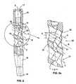
- the proximal portion 14also comprises, in correspondence with the head 15 of the nail 10, a seat 17 ( figure 2 ) for the insertion of corresponding instruments for the nail 10 manipulation, such as for example the one being described in said patent EP 0 853 923 in the name of the Applicant.
- a third hole 19is obtained in this specific case between the first and the second hole 20, 21 for the insertion of a wire for controlling the position and depth of cephalic screws 22, 23, 24 and 25.
- the passage 30, in this case the closest to the head 15 of the nail 10has an axis A forming an angle with the axis C of the second hole 21, while the second passage 31, i.e. the farthest from the head 15 of the nail 10, has an axis B being substantially parallel to the axis C of the second hole 21.
- the first passage 30forms an angle ⁇ of about 115° with the axis X of the proximal portion 14 of the endomedullary nail 10, while the second passage 31, and similarly the second proximal hole 21, form and angle ⁇ of about 123° with the axis X of the proximal portion 14 of the nail 10.
- the first passage 30 and the second passage 31are convergent towards the femur head with a convergence angle of about 8°.
- both passages 30, 31have a diameter of 8,5 mm and the distance E between the corresponding axes A and B, measured along the axis X of the proximal portion 14, is of some millimetres, about 2 mm.
- both the two passages 30, 31 and the second hole 21are equipped with a thread for the cephalic screw engagement.
- the presence of the two passages 30, 31 with a differently sloping axisallows a single endomedullary nail 10 to be alternately configured according to two different configurations.
- the present inventionalso relates to a device for the treatment of proximal femur fractures comprising the above-described endomedullary nail 10 and the cephalic screws 22, 23, 24, 25.
- the devicecomprises four cephalic screws 22, 23, 24, 25 which will be described hereafter.
- the two cephalic screws 22, 23are of the so-called dynamic type, i.e. screws, which can slide with respect to the nail 10.
- the embedded hexagon wall or the screw cannulationis preferably threaded in order to allow the tool to be eventually fixed in an extraction step of the cephalic screws from the nail.
- the devicealso comprises a sleeve 42 wherein the stem 40 of the screw 22, 23 is slidingly inserted.
- the thread 43 of the sleeve 42has an apparent pitch corresponding to half the pitch of the self-threading thread 38 of the screw 22, 23 to penetrate into the bone.
- the device according to the inventioncomprises two cephalic screws 24, 25 of the so-called static type, suitable to be screwed both into the nail 10 and into the bone.
- screws 24, 25( figure 3 ) having a uniform resistance, equipped each with a first self-threading thread 50 self penetrating into the femur head and with a second thread 51 to be screwed with the nail 10. It must also be noted that the screws 24, 25 have a bulge 55 in correspondence with the connection area with the nail 10 to allow the screwing thereof.
- the screwsare equipped with an embedded hexagon preferably equipped with the corresponding thread.
- the two cephalic screws 24, 25are directly inserted into the first passage 30 and into the second hole 21 respectively. Afterwards, the distal pin 28 is inserted into the hole 26.
- the second thread 51has an apparent pitch corresponding to half the pitch of the first thread 50 to penetrate into the bone, allowing the screw to constantly advance into the bone and into the nail 10. A stiff constraint is thus obtained between the two screws 24, 25 and the nail 10.
- the main advantage of the endomedullary nail according to the present inventionis that a single endomedullary nail is used to obtain two different cephalic screw configurations, such as for example the parallel-axis one and the convergent-axis one.
- the cephalic screwwhen inserted into one passage or into the other, keeps its axial position along the nail proximal portion.
- the distance between the two cephalic screwsis substantially constant.
- each screwin both configurations, is kept in a position substantially corresponding to the position it would have had in a traditional nail equipped with two circular holes.
- the nail 10is not excessively weakened by the presence of the double passage.
- Another advantageis that a surgeon can choose directly in the operating room, according to the situation he is facing, if the screw 22, 24 is to be inserted into one passage or into the other 30, 31 of the first hole 20, in order to change the angle relationship thereof with respect to the other screw 23 and 25 of the second hole 21, and without removing the nail 10 from the medullar cavity.
- the choice of the two predetermined angles of inclination (about 115° and 123° respectively) of the two passages 30, 31 and of the second hole 21 for the static and dynamic configuration respectively,is particularly suitable for a complete containment of a pertrochanteric fracture.
- Another advantage of the present inventionis that, according to the screw configuration, a static or dynamic device for the treatment of proximal femur fractures can be obtained by means of a single nail.
- the sliding cephalic screws equipped with the corresponding sleevecan be inserted into the parallel-axis holes.
Landscapes
- Health & Medical Sciences (AREA)
- Orthopedic Medicine & Surgery (AREA)
- Surgery (AREA)
- Life Sciences & Earth Sciences (AREA)
- Heart & Thoracic Surgery (AREA)
- Nuclear Medicine, Radiotherapy & Molecular Imaging (AREA)
- Engineering & Computer Science (AREA)
- Biomedical Technology (AREA)
- Neurology (AREA)
- Medical Informatics (AREA)
- Molecular Biology (AREA)
- Animal Behavior & Ethology (AREA)
- General Health & Medical Sciences (AREA)
- Public Health (AREA)
- Veterinary Medicine (AREA)
- Surgical Instruments (AREA)
Description
- The present invention generally relates to an endomedullary nail for the treatment of proximal femur fractures, such as for example pertrochanteric fractures whose fissure extends from the lesser to the greater trochanter, medial fractures and at the base of the femur neck, and the like.
- The nail comprises an elongate body having a proximal portion and a distal portion. In the proximal portion thereof, the nail also comprises a first and a second hole, each having a transversal axis to the proximal portion axis for a corresponding cephalic screw.
- The present invention also relates to a device for the treatment of proximal femur fractures comprising the above-mentioned nail and the corresponding cephalic screws.
- The now widespread use of endomedullary nails as above for the osteosynthesis of proximal femur fractures is known.
- Fracture stabilisation is mainly obtained by means of two cephalic screws. The latter are inserted transversally to the nail into two respective circular holes of the proximal portion so as to cross the femur neck spongiosis up to reach the femur head in order to allow a mutual stump compression.
- The cephalic screw arrangement and orientation with respect to the endomedullary nail substantially depend on the fracture type. In particular, according to the seriousness, the femur neck composing structure, the patient's age and the trauma type, fragments and fissures, which are different from each other, can be formed.
- In most known nails, the two holes for cephalic screws have parallel axes.
- On the contrary, for other types of trauma, mainly in case of serious pertrochanteric fractures, wherein it is necessary to ensure a certain nail and screw staticity, the two proximal holes have convergent axes. Therefore cephalic screws, once being inserted into the femur neck, mutually converge ensuring a high stabilisation thereof and of the head. A nail with convergent-axis holes is known for example from the patent
EP 0 853 923 in the name of the Applicant. - A further intramedullary femoral nail for the treatment of fractures is known from
US 5, 549, 610 A (The preamble of claim 1 is based on this document.) in the name of RUSSEL et al. The nail includes three proximal locking screw passageways, two parallel upwardly oblique passageways and a single downwardly oblique passageway. The two parallel upwardly oblique passageways are suitable for the insertion of two cephalic screws in the head of the femur in reconstruction mode and the single downwardly oblique passageway is suitable for insertion of one screw transversally in the neck of the femur in a femoral mode. - Another nail is known from the
Japanese patent application JP 2002253566 - However; known nails, although ensuring a complete fracture stabilisation, have recognised drawbacks being not yet overcome.
- The main drawback is that, just to ensure the containment of a particular type of fracture, the nail and cephalic screw configuration is substantially predetermined, restraining and limiting the possibility to change the endomedullary nail application in different traumatic situations.
- It results that the use of known endomedullary nails for the stabilisation of fractures having a different nature is considerably limited, since this would inevitably involve a wrong arrangement and orientation of the two cephalic screws.
- This drawback is even more serious when considering that, according to the type of femur fracture, a surgeon is obliged to exclusively choose preliminarily, i.e. before the intervention, the endomedullary nail to be used and he cannot change the orientation of the two cephalic screws when the nails has already been implanted.
- The technical problem underlying the present invention is thus to provide an endomedullary nail overcoming the above-mentioned drawbacks of known endomedullary nails in order to have a higher application versatility and, particularly, allowing a surgeon to change the cephalic screw configuration when operating during the surgical intervention, without requiring the nail removal from the medullar cavity.
- This technical problem is solved by an endomedullary nail according to claim 1, wherein, while the second hole has a circular cross section, the first hole is split into two passages arranged for being selectively engaged by a respective cephalic screw and having each a predetermined angle relationship with respect to the second hole axis.
- The features and advantages of the endomedullary nail according to the invention will be apparent from the following description of an embodiment thereof given by way of non limiting example with reference to the attached drawings.
Figure 1 is a front view of the nail according to the present invention.Figure 2 is an enlarged-scale cross section along the line II-II offigure 1 .Figure 2a shows a further enlarged detail offigure 2 .Figure 3 shows a first cephalic screw for the endomedullary nail offigure 1 .Figure 4 shows a second cephalic screw with sliding sleeve for the endomedullary nail offigure 1 .Figure 5 shows the cephalic screw offigure 4 .Figure 6 shows in enlarged scale the sleeve offigure 4 .Figure 7 shows a cross section of the sleeve offigure 6 .Figure 8 shows the nail offigure 1 in a first configuration.Figure 9 shows the nail offigure 1 in a second configuration.- With reference to the attached drawings, an endomedullary nail for the treatment of proximal femur fractures according to the present invention is generally indicated with the
reference number 10 - The
nail 10 comprises anelongate body 12, preferably made of titanium, having ahead 15, aproximal portion 14 and adistal portion 16. The twoportions - The
proximal portion 14 also comprises, in correspondence with thehead 15 of thenail 10, a seat 17 (figure 2 ) for the insertion of corresponding instruments for thenail 10 manipulation, such as for example the one being described in said patentEP 0 853 923 in the name of the Applicant. - In this specific case, the
proximal portion 14 has a higher diameter than thedistal portion 16 and it is connected thereto by means of a substantially cone-shaped connectingportion 18. - In the
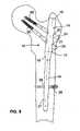
distal portion 16 theendomedullary nail 10 comprises ahole 26 and aslot 27 for corresponding distal pins 28 (fig. 8 and9 ). - In the
proximal portion 14 theendomedullary nail 10 comprises, starting from thehead 15, a first and asecond hole cephalic screws figures 3, 4, 5 ,8 ,9 ). - A
third hole 19 is obtained in this specific case between the first and thesecond hole cephalic screws - According to the invention, while the second
proximal hole 21 has a substantially circular cross section and it extends with an axis C sloping on the axis X of theproximal portion 14, thefirst hole 20 is split into two passages being arranged to be selectively engaged by a respectivecephalic screw second hole 21, in order to obtain a different orientation of the cephalic screws being inserted therein. - Preferably the
first hole 20 has a substantially "eight-shaped" cross section defined by twopassages passages proximal hole 20, are each substantially cylinder-shaped and longitudinally interfering. - Preferably the two
passages - In particular, with reference to
figures 2 and 2a , thepassage 30, in this case the closest to thehead 15 of thenail 10, has an axis A forming an angle with the axis C of thesecond hole 21, while thesecond passage 31, i.e. the farthest from thehead 15 of thenail 10, has an axis B being substantially parallel to the axis C of thesecond hole 21. - In the case of the shown solution, the
first passage 30 forms an angle α of about 115° with the axis X of theproximal portion 14 of theendomedullary nail 10, while thesecond passage 31, and similarly the secondproximal hole 21, form and angle β of about 123° with the axis X of theproximal portion 14 of thenail 10. - Therefore, the
first passage 30 and thesecond passage 31 are convergent towards the femur head with a convergence angle of about 8°. - In the specific case of the solution shown in the drawings, both
passages proximal portion 14, is of some millimetres, about 2 mm. - As it will be better seen hereafter, both the two
passages second hole 21 are equipped with a thread for the cephalic screw engagement. - As above disclosed, the presence of the two
passages endomedullary nail 10 to be alternately configured according to two different configurations. - In this specific case, in a first configuration (
figure 8 ), the twoscrews second passage 31 of thefirst hole 20 and into thesecond hole 21 respectively, in order to be substantially parallel. - In a second configuration (
figure 9 ), the twoscrews first passage 30 of thefirst hole 20 and into thesecond hole 21 respectively, in order to converge towards the femur head. - According to another aspect, the present invention also relates to a device for the treatment of proximal femur fractures comprising the above-described
endomedullary nail 10 and thecephalic screws - In particular, according to the invention the device comprises four
cephalic screws - In the first configuration, i.e. the parallel-axis one, the two
cephalic screws nail 10. - In particular, the
screws 22, 23 (figures 4, 5, 6, 7 ) comprise a single self-threading thread 38 self-penetrating into the femur head, and a cylinder-shaped stem 40 equipped, in the head area, with an embedded hexagon for a convenient working tool. - Moreover the embedded hexagon wall or the screw cannulation is preferably threaded in order to allow the tool to be eventually fixed in an extraction step of the cephalic screws from the nail.
- The device also comprises a
sleeve 42 wherein thestem 40 of thescrew - The
sleeve 42 comprises, in a central area, anexternal thread 43 for being screwed into theproximal holes sharp profiles 44 can be obtained at a first end of thesleeve 42 in order to allow the advance thereof into the bone and, at a second end, ascrewdriver slot 46 for the connection to a convenient instrument. - In this specific case, the
thread 43 of thesleeve 42 has an apparent pitch corresponding to half the pitch of the self-threadingthread 38 of thescrew - The arrangement of the two
cephalic screws sleeve 42 in the parallel-axis configuration is performed as follows. - After inserting the
nail 10 into the medullar cavity, thecephalic screws second passage 31 and into thesecond hole 21 respectively together with thesleeve 42 and screwed into the femur head. Therefore thesleeve 42 is inserted together with thescrews passage 31 and into thehole 21. - It must be noted that, doing so, only the
sleeve 42 is screwed into thenail 10, ensuring certain dynamicity and movement elasticity to thescrews endomedullary nail 10. - At a second point, the
pin 28 is preferably inserted into theslot 27 in order to prevent thenail 10 rotation. - In the second configuration (
figure 9 ), i.e. the convergent-axis one, the device according to the invention comprises twocephalic screws nail 10 and into the bone. - In particular, they are
screws 24, 25 (figure 3 ) having a uniform resistance, equipped each with a first self-threadingthread 50 self penetrating into the femur head and with asecond thread 51 to be screwed with thenail 10. It must also be noted that thescrews bulge 55 in correspondence with the connection area with thenail 10 to allow the screwing thereof. - In this case too, the screws are equipped with an embedded hexagon preferably equipped with the corresponding thread.
- The arrangement of the two
cephalic screws - After inserting the
nail 10 into the medullar cavity, the twocephalic screws first passage 30 and into thesecond hole 21 respectively. Afterwards, thedistal pin 28 is inserted into thehole 26. - In this case too, the
second thread 51 has an apparent pitch corresponding to half the pitch of thefirst thread 50 to penetrate into the bone, allowing the screw to constantly advance into the bone and into thenail 10. A stiff constraint is thus obtained between the twoscrews nail 10. - The main advantage of the endomedullary nail according to the present invention is that a single endomedullary nail is used to obtain two different cephalic screw configurations, such as for example the parallel-axis one and the convergent-axis one.
- Moreover, since the two
passages - Therefore, passing from a configuration to the other, the distance between the two cephalic screws, conveniently adapted to the femur neck size, is substantially constant.
- This allows only a screw angle orientation change to be obtained between the two configurations. Therefore each screw, in both configurations, is kept in a position substantially corresponding to the position it would have had in a traditional nail equipped with two circular holes.
- Moreover, due to the integration in a single slot, the
nail 10 is not excessively weakened by the presence of the double passage. - Another advantage is that a surgeon can choose directly in the operating room, according to the situation he is facing, if the
screw first hole 20, in order to change the angle relationship thereof with respect to theother screw second hole 21, and without removing thenail 10 from the medullar cavity. - In particular, the choice of the two predetermined angles of inclination (about 115° and 123° respectively) of the two
passages second hole 21 for the static and dynamic configuration respectively, is particularly suitable for a complete containment of a pertrochanteric fracture. - Another advantage of the present invention is that, according to the screw configuration, a static or dynamic device for the treatment of proximal femur fractures can be obtained by means of a single nail.
- In fact, when it is necessary, in response to specific stresses, to ensure certain device dynamicity, the sliding cephalic screws equipped with the corresponding sleeve can be inserted into the parallel-axis holes.
- It must be noted that it is possible to obtain also the dynamicity of the nail distal portion. It is obtained by inserting a single pin into the distal slot. In fact it does not constrain a nail movement, caused for example by a possible axial stress.
- Similarly, when absolute stress stiffness is required, the double-threaded screws are screwed into the convergent-axis holes.
- It must be noted in this case too that, in the convergent-axis configuration, the staticity is kept also at the level of
distal portion 16 of thenail 10, since thepin 28 is inserted only into thecircular hole 26. - Therefore, the choice for stability or dynamicity, not only for the femur cephalic portion, but also for the femur central portion, or diaphysis, is thus performed according to the type of fracture and it is not constrained by the device being used.
Claims (17)
- An endomedullary nail for the treatment of proximal femur fractures, comprising an elongate body (12) having a proximal portion (14) and a distal portion (16), the proximal portion (14) having a first and a second hole (20, 21) for a respective cephalic screw (22, 23, 24, 25), each having a transversal axis to the axis (X) of the proximal portion (14),characterised in that the first hole (20) is split into two passages (30, 31) wherein the two passages (30, 31) are adjacent and longitudinally open the one into the other, so that the first hole (20) has a substantially "eight-shaped" cross section, each of the two passages (30, 31) having a respective axis (A, B) with a predetermined angle relationship with respect to the axis of the second hole (21), and wherein said passages (30, 31) are arranged to be selectively engaged by a respective cephalic screw (22, 24).
- A nail according to claim 1,characterised in that said passages (30, 31) have respective axes (A, B) converging with a predetermined convergence axis intended to be turned towards the femur head.
- A nail according to claim 1,characterised in that a first of said passages (30) has the axis (A) forming an angle with the axis (C) of the second hole (21), while a second of said passages (31) has the axis (B) being substantially parallel to the axis (C) of the second hole (21).
- A nail according to claim 2,characterised in that the axis (A) of the first passage (30) forms with the axis (B) of the second passage (31) an angle of about 8°.
- A nail according to claim 1,characterised in that the first passage (30) forms an angle of about 115° with the axis (X) of the proximal portion (14).
- A nail according to claim 1,characterised in that the second passage (31) forms an angle of about 123° with the axis (X) of the proximal portion (14).
- A nail according to claim 1,characterised in that the distance between the axis (A) of the first passage (30) and the axis (B) of the second passage (31) measured along the axis (X) of the proximal portion (14) corresponds to about 2 mm.
- A nail according to claim 1, wherein both the two passages (30, 31) and the second hole (21) are equipped with a thread for the cephalic screw (22, 23, 24, 25) engagement.
- A device for the treatment of proximal femur fractures comprising an endomedullary nail (10) according to claim 1 and cephalic screws (22, 23, 24, 25) suitable for insertion into the two respective proximal holes (20, 21) of the endomedullary nail (10).
- A device according to claim 9, comprising two first cephalic screws (22, 23), which are suitable for insertion in the second passage (31) of the first hole (20) and in the second hole (21) respectively to obtain a first configuration and two second screws (24, 25) which are suitable for insertion in the first passage (30) of the first hole (20) and in the second hole (21) respectively to obtain a second configuration alternately to the first configuration.
- A device according to claim 10,characterised in that a first of said passages (30) has the axis (A) forming an angle with the axis (C) of the second hole (21), while a second of said passages (31) has the axis (B) being substantially parallel to the axis (C) of the second hole (21).
- A device according to claim 11, wherein each of the two first cephalic screws (22, 23) has a self-threading thread (38) to be screwed into the bone and a smooth stem (40) to be slidingly inserted into the second passage (31) of the first hole (20) and into the second proximal hole (21) respectively in order to be positioned parallel to each other obtaining a dynamic configuration.
- A device according to claim 11, wherein each of the two second cephalic screws (24, 25) has a first self-threading thread (50) to be screwed into the bone and a second thread (51) to be screwed into the first passage (30) of the first hole (20) and into the second proximal hole (21) respectively in order to be positioned convergent to each other obtaining a static configuration.
- A device according to claim 12,characterised in that it comprises two sleeves (42) having an external thread (43) to be screwed into the second passage (31) of the first hole (20) and into the second proximal hole (21) respectively and wherein the stems (40) of the first cephalic screws (22, 23) are slidingly inserted.
- A device according to claim 14,characterised in that each sleeve (42) comprises sharp profiles (44) to advance into the bone.
- A device according to claim 14,characterised in that the external thread (43) of the sleeves (42) has an apparent pitch corresponding to half the pitch of the self-threading thread (38) of the first screw (22, 23) to penetrate into the bone.
- A device according to claim 13,characterised in that the second thread (51) of the second cephalic screws (24, 25) has an apparent pitch corresponding to half the pitch of the first self-threading thread (50).
Priority Applications (12)
| Application Number | Priority Date | Filing Date | Title |
|---|---|---|---|
| ES04425717TES2306976T3 (en) | 2004-09-27 | 2004-09-27 | INTRAMEDULAR SCREW FOR THE TREATMENT OF FEMUR PROXIMAL FRACTURES. |
| AT04425717TATE395871T1 (en) | 2004-09-27 | 2004-09-27 | INTEGRAL NAIL FOR THE TREATMENT OF PROXIMAL FEMUR Fractures |
| DK04425717TDK1639953T3 (en) | 2004-09-27 | 2004-09-27 | Endomedullary stitch for the treatment of proximal femur fractures |
| DE602004013971TDE602004013971D1 (en) | 2004-09-27 | 2004-09-27 | Intramedullary nail for the treatment of proximal femoral fractures |
| EP04425717AEP1639953B1 (en) | 2004-09-27 | 2004-09-27 | Intramedullary nail for the treatment of proximal femur fractures |
| US11/233,475US7670340B2 (en) | 2004-09-27 | 2005-09-21 | Endomedullary nail for the treatment of proximal femur fractures |
| BRPI0504202ABRPI0504202B8 (en) | 2004-09-27 | 2005-09-23 | endomedullary nail and device for the treatment of proximal femur fractures |
| ARP050104045AAR055490A1 (en) | 2004-09-27 | 2005-09-26 | DESTINATED ENDOMEDULAR NAIL OF PROXIMAL FEMUR FRACTURES |
| CA2521234ACA2521234C (en) | 2004-09-27 | 2005-09-26 | Endomedullary nail for the treatment of proximal femur fractures |
| JP2005280239AJP4729376B2 (en) | 2004-09-27 | 2005-09-27 | Intramedullary nail and device for treatment of proximal femoral fractures using the intramedullary nail |
| CNB2005101069683ACN100534400C (en) | 2004-09-27 | 2005-09-27 | Intramedullary nail for the treatment of proximal femur fractures and device |
| CR8012ACR8012A (en) | 2004-09-27 | 2005-09-27 | ENDOMEDULAR NAIL FOR THE TREATMENT OF PROXIMAL FEMUR FRACTURES |
Applications Claiming Priority (1)
| Application Number | Priority Date | Filing Date | Title |
|---|---|---|---|
| EP04425717AEP1639953B1 (en) | 2004-09-27 | 2004-09-27 | Intramedullary nail for the treatment of proximal femur fractures |
Publications (2)
| Publication Number | Publication Date |
|---|---|
| EP1639953A1 EP1639953A1 (en) | 2006-03-29 |
| EP1639953B1true EP1639953B1 (en) | 2008-05-21 |
Family
ID=34932783
Family Applications (1)
| Application Number | Title | Priority Date | Filing Date |
|---|---|---|---|
| EP04425717AExpired - LifetimeEP1639953B1 (en) | 2004-09-27 | 2004-09-27 | Intramedullary nail for the treatment of proximal femur fractures |
Country Status (12)
| Country | Link |
|---|---|
| US (1) | US7670340B2 (en) |
| EP (1) | EP1639953B1 (en) |
| JP (1) | JP4729376B2 (en) |
| CN (1) | CN100534400C (en) |
| AR (1) | AR055490A1 (en) |
| AT (1) | ATE395871T1 (en) |
| BR (1) | BRPI0504202B8 (en) |
| CA (1) | CA2521234C (en) |
| CR (1) | CR8012A (en) |
| DE (1) | DE602004013971D1 (en) |
| DK (1) | DK1639953T3 (en) |
| ES (1) | ES2306976T3 (en) |
Families Citing this family (56)
| Publication number | Priority date | Publication date | Assignee | Title |
|---|---|---|---|---|
| US7780667B2 (en)* | 2003-09-08 | 2010-08-24 | Smith & Nephew, Inc. | Orthopaedic plate and screw assembly |
| US7799030B2 (en)* | 2003-09-08 | 2010-09-21 | Smith & Nephew, Inc. | Orthopaedic plate and screw assembly |
| US20050055024A1 (en)* | 2003-09-08 | 2005-03-10 | James Anthony H. | Orthopaedic implant and screw assembly |
| US20070155271A1 (en)* | 2005-12-30 | 2007-07-05 | Touzov Igor V | Heat conductive textile and method producing thereof |
| US9320551B2 (en) | 2007-01-26 | 2016-04-26 | Biomet Manufacturing, Llc | Lockable intramedullary fixation device |
| US9308031B2 (en) | 2007-01-26 | 2016-04-12 | Biomet Manufacturing, Llc | Lockable intramedullary fixation device |
| US7918853B2 (en)* | 2007-03-20 | 2011-04-05 | Smith & Nephew, Inc. | Orthopaedic plate and screw assembly |
| AU2008256740A1 (en) | 2007-05-25 | 2008-12-04 | Zimmer, Gmbh | Reinforced intramedullary nail |
| KR101503665B1 (en) | 2007-06-22 | 2015-03-18 | 이픽스 오소페딕스, 인코포레이티드 | Intramedullary rod for pivoting a fastener |
| JP5335220B2 (en)* | 2007-11-08 | 2013-11-06 | 株式会社ホリックス | Intramedullary nail and method for joining fracture sites using intramedullary nail |
| CA2781407A1 (en) | 2008-01-14 | 2009-07-23 | Michael P. Brenzel | Apparatus and methods for fracture repair |
| CN104068925B (en) | 2008-03-26 | 2017-07-14 | 斯恩蒂斯有限公司 | For the universal anchor by physical attachment on bone tissue |
| US20110046625A1 (en)* | 2008-05-07 | 2011-02-24 | Tornier | Surgical technique and apparatus for proximal humeral fracture repair |
| CN102046111A (en) | 2008-06-05 | 2011-05-04 | 斯恩蒂斯有限公司 | Articulating disc implant |
| US8328806B2 (en)* | 2008-06-24 | 2012-12-11 | Extremity Medical, Llc | Fixation system, an intramedullary fixation assembly and method of use |
| US20110230884A1 (en)* | 2008-06-24 | 2011-09-22 | Adam Mantzaris | Hybrid intramedullary fixation assembly and method of use |
| US8313487B2 (en)* | 2008-06-24 | 2012-11-20 | Extremity Medical Llc | Fixation system, an intramedullary fixation assembly and method of use |
| US9044282B2 (en) | 2008-06-24 | 2015-06-02 | Extremity Medical Llc | Intraosseous intramedullary fixation assembly and method of use |
| US8343199B2 (en)* | 2008-06-24 | 2013-01-01 | Extremity Medical, Llc | Intramedullary fixation screw, a fixation system, and method of fixation of the subtalar joint |
| US9289220B2 (en) | 2008-06-24 | 2016-03-22 | Extremity Medical Llc | Intramedullary fixation assembly and method of use |
| US8303589B2 (en) | 2008-06-24 | 2012-11-06 | Extremity Medical Llc | Fixation system, an intramedullary fixation assembly and method of use |
| US9017329B2 (en)* | 2008-06-24 | 2015-04-28 | Extremity Medical, Llc | Intramedullary fixation assembly and method of use |
| US8790343B2 (en) | 2008-10-11 | 2014-07-29 | Epix Orthopaedics, Inc. | Intramedullary rod with pivotable and fixed fasteners and method for using same |
| ES2524076T3 (en) | 2008-10-15 | 2014-12-04 | Zimmer Gmbh | Intramedullary nail |
| US9060808B2 (en)* | 2008-12-05 | 2015-06-23 | DePuy Synthes Products, Inc. | Anchor-in-anchor system for use in bone fixation |
| US8834469B2 (en) | 2009-06-30 | 2014-09-16 | Smith & Nephew, Inc. | Orthopaedic implant and fastener assembly |
| US8449544B2 (en) | 2009-06-30 | 2013-05-28 | Smith & Nephew, Inc. | Orthopaedic implant and fastener assembly |
| US20110178520A1 (en) | 2010-01-15 | 2011-07-21 | Kyle Taylor | Rotary-rigid orthopaedic rod |
| WO2011091052A1 (en) | 2010-01-20 | 2011-07-28 | Kyle Taylor | Apparatus and methods for bone access and cavity preparation |
| US8556896B2 (en)* | 2010-01-27 | 2013-10-15 | Zimmer, Inc. | Distal relief for a surgical device |
| CA2829196A1 (en)* | 2010-03-08 | 2011-09-15 | Conventus Orthopaedics, Inc. | Apparatus and methods for bone repair |
| WO2011112615A1 (en) | 2010-03-08 | 2011-09-15 | Krinke Todd A | Apparatus and methods for securing a bone implant |
| USD638125S1 (en)* | 2010-04-13 | 2011-05-17 | Zimmer, Gmbh | Intramedullary nail |
| USD638126S1 (en)* | 2010-04-13 | 2011-05-17 | Zimmer, Gmbh | Intramedullary nail |
| US8540714B2 (en) | 2010-05-11 | 2013-09-24 | Orthopediatrics Corp. | Pediatric intramedullary nail |
| CA2847608C (en)* | 2011-09-16 | 2016-07-05 | Stryker Trauma Gmbh | Polyaxial locking hole arrangement |
| US9265541B2 (en)* | 2011-10-28 | 2016-02-23 | Stryker Trauma Gmbh | Intramedullary nail locking hole arrangement |
| JP6247644B2 (en) | 2012-02-08 | 2017-12-13 | エピックス オーソペディックス インコーポレイテッド | Implant insertion device having a continuously adjustable targeting assembly |
| DE202012103384U1 (en)* | 2012-09-05 | 2012-09-24 | Signus Medizintechnik Gmbh | Pelvic ring implant |
| US10123828B2 (en) | 2013-03-15 | 2018-11-13 | Epix Orthopaedics, Inc. | Implantable device with pivotable fastener and self-adjusting set screw |
| ES2805053T3 (en)* | 2013-12-09 | 2021-02-10 | Acumed Llc | Nail-based elastic hip fixation system |
| US10080596B2 (en) | 2013-12-09 | 2018-09-25 | Acumed Llc | Hip fixation with load-controlled dynamization |
| CN105939677A (en) | 2013-12-12 | 2016-09-14 | 康文图斯整形外科公司 | Tissue displacement tools and methods |
| US9517094B1 (en)* | 2014-05-09 | 2016-12-13 | Savage Medical Design LLC | Intramedullary fixation apparatus for use in hip and femur fracture surgery |
| DE102014113556A1 (en)* | 2014-09-19 | 2016-03-24 | Königsee Implantate GmbH | Osteosynthesis aids for the treatment of subtrochanteric fractures and / or pertrochanteric fractures and / or femoral neck fractures |
| US9895177B2 (en) | 2016-01-15 | 2018-02-20 | ARTHREX, GmbH | Bone fixation device for treatment of femoral fractures |
| CN105997219B (en)* | 2016-06-30 | 2018-06-22 | 王永清 | Lock multidirectional intramedullary nail with lock |
| US10874433B2 (en) | 2017-01-30 | 2020-12-29 | Stryker European Holdings I, Llc | Strut attachments for external fixation frame |
| WO2019010252A2 (en) | 2017-07-04 | 2019-01-10 | Conventus Orthopaedics, Inc. | APPARATUS AND METHODS FOR TREATING BONES |
| US11446072B2 (en) | 2017-10-10 | 2022-09-20 | DePuy Synthes Products, Inc. | Self-retaining nail to insertion handle interface |
| MX2020003481A (en) | 2017-10-11 | 2020-12-07 | Howmedica Osteonics Corp | Humeral fixation plate guides. |
| CN107714168B (en)* | 2017-11-03 | 2023-04-21 | 山东大学齐鲁医院(青岛) | Orthopedics double-locking fixed block and double-locking individuation internal fixation device |
| ES3034064T3 (en) | 2018-04-13 | 2025-08-12 | Stryker European Operations Holdings Llc | Femoral nail with enhanced bone conforming geometry |
| TR202008814A2 (en)* | 2020-06-08 | 2021-03-22 | Acibadem Mehmet Ali Aydinlar Ueniversitesi | AN ORTHOPEDIC IMPLANT |
| US12004785B2 (en) | 2022-04-21 | 2024-06-11 | DePuy Synthes Products, Inc. | Retrograde femoral intramedullary nail, and related systems and methods |
| CN118303961B (en)* | 2024-03-25 | 2024-10-18 | 中国人民解放军总医院第四医学中心 | Elastic intramedullary fixation device |
Family Cites Families (23)
| Publication number | Priority date | Publication date | Assignee | Title |
|---|---|---|---|---|
| US2475025A (en)* | 1946-10-26 | 1949-07-05 | Universal Oil Prod Co | Reactor for close temperature control |
| US2500519A (en)* | 1947-10-14 | 1950-03-14 | Phillips Petroleum Co | Process and apparatus for the synthesis of hydrocarbons |
| US2759878A (en)* | 1951-04-26 | 1956-08-21 | Union Oil Co | Process for treating hydrocarbons in a moving bed with solid particles at different temperature levels |
| US2852545A (en)* | 1954-02-15 | 1958-09-16 | Frank J Jenny | Method and apparatus for synthesizing hydrocarbons |
| US3094479A (en)* | 1958-02-07 | 1963-06-18 | Sweeney Maxwell Patrick | Conversion process and apparatus |
| DE1542494C3 (en)* | 1966-07-21 | 1975-06-05 | Veba-Chemie Ag, 4660 Gelsenkirchenbuer | Device for carrying out catalytic reactions |
| US4640271A (en)* | 1985-11-07 | 1987-02-03 | Zimmer, Inc. | Bone screw |
| FR2698261B1 (en)* | 1992-11-24 | 1995-03-17 | Lacaffiniere Jean Yves De | Device for guiding a double screw of the neck of the femur for locked trochantero-diaphyseal nail. |
| US6030162A (en)* | 1998-12-18 | 2000-02-29 | Acumed, Inc. | Axial tension screw |
| US5549610A (en)* | 1994-10-31 | 1996-08-27 | Smith & Nephew Richards Inc. | Femoral intramedullary nail |
| DK0715832T3 (en)* | 1994-11-17 | 2002-04-22 | Treu Instr Gmbh | Marrow seam for hip compression |
| IT1293934B1 (en)* | 1997-01-21 | 1999-03-11 | Orthofix Srl | ENDOMIDOLLAR NAIL FOR THE TREATMENT OF HIP FRACTURES |
| US20040069454A1 (en)* | 1998-11-02 | 2004-04-15 | Bonsignore Patrick V. | Composition for enhancing thermal conductivity of a heat transfer medium and method of use thereof |
| ES2214071T3 (en)* | 1999-12-03 | 2004-09-01 | Synthes Ag Chur | INTRAMEDULAR KEY. |
| US6619383B2 (en)* | 2000-07-25 | 2003-09-16 | Arthur M. Squires | Vibrated-bed method and apparatus for heat exchange |
| JP4418122B2 (en)* | 2001-03-01 | 2010-02-17 | 瑞穂医科工業株式会社 | Intramedullary nail |
| US7096931B2 (en)* | 2001-06-08 | 2006-08-29 | Exxonmobil Research And Engineering Company | Increased heat exchange in two or three phase slurry |
| GB0116894D0 (en)* | 2001-07-11 | 2001-09-05 | Accentus Plc | Catalytic reactor |
| GB0125035D0 (en)* | 2001-10-18 | 2001-12-12 | Accentus Plc | Catalytic reactor |
| US7001386B2 (en)* | 2002-07-23 | 2006-02-21 | Advanced Orthopaedic Solutions, Inc. | Intramedullary nail for long bone fractures |
| CN2609515Y (en)* | 2002-07-28 | 2004-04-07 | 王永清 | Compound intramedullary nail with lock for femur |
| JP3977205B2 (en)* | 2002-08-29 | 2007-09-19 | 有限会社ケイオーアイ | Intramedullary nail |
| US7108835B2 (en)* | 2003-10-08 | 2006-09-19 | Rentech, Inc. | Fischer-tropsch slurry reactor cooling tube arrangement |
- 2004
- 2004-09-27ESES04425717Tpatent/ES2306976T3/ennot_activeExpired - Lifetime
- 2004-09-27EPEP04425717Apatent/EP1639953B1/ennot_activeExpired - Lifetime
- 2004-09-27ATAT04425717Tpatent/ATE395871T1/enactive
- 2004-09-27DKDK04425717Tpatent/DK1639953T3/enactive
- 2004-09-27DEDE602004013971Tpatent/DE602004013971D1/ennot_activeExpired - Lifetime
- 2005
- 2005-09-21USUS11/233,475patent/US7670340B2/enactiveActive
- 2005-09-23BRBRPI0504202Apatent/BRPI0504202B8/ennot_activeIP Right Cessation
- 2005-09-26ARARP050104045Apatent/AR055490A1/ennot_activeApplication Discontinuation
- 2005-09-26CACA2521234Apatent/CA2521234C/ennot_activeExpired - Fee Related
- 2005-09-27JPJP2005280239Apatent/JP4729376B2/ennot_activeExpired - Fee Related
- 2005-09-27CNCNB2005101069683Apatent/CN100534400C/enactiveActive
- 2005-09-27CRCR8012Apatent/CR8012A/enunknown
Also Published As
| Publication number | Publication date |
|---|---|
| CA2521234A1 (en) | 2006-03-27 |
| CA2521234C (en) | 2010-11-30 |
| CR8012A (en) | 2009-01-07 |
| ATE395871T1 (en) | 2008-06-15 |
| BRPI0504202B1 (en) | 2015-12-08 |
| US7670340B2 (en) | 2010-03-02 |
| DK1639953T3 (en) | 2008-09-29 |
| JP4729376B2 (en) | 2011-07-20 |
| ES2306976T3 (en) | 2008-11-16 |
| BRPI0504202A (en) | 2006-05-09 |
| CN1754521A (en) | 2006-04-05 |
| EP1639953A1 (en) | 2006-03-29 |
| AR055490A1 (en) | 2007-08-22 |
| BRPI0504202B8 (en) | 2021-06-22 |
| CN100534400C (en) | 2009-09-02 |
| US20060069392A1 (en) | 2006-03-30 |
| JP2006095306A (en) | 2006-04-13 |
| DE602004013971D1 (en) | 2008-07-03 |
Similar Documents
| Publication | Publication Date | Title |
|---|---|---|
| EP1639953B1 (en) | Intramedullary nail for the treatment of proximal femur fractures | |
| JP2538470B2 (en) | Bone screw | |
| US10492838B2 (en) | Flexible bone implant | |
| US10485595B2 (en) | Flexible bone screw | |
| US7780664B2 (en) | Endosteal nail | |
| US9247975B2 (en) | Bone screw set | |
| US20070173834A1 (en) | Flexible Nail Assembly For Fractures Of Long Bones | |
| EP2162082B1 (en) | Surgical drill guide having keyway for axial alignment of fastener used for an orthopedic plate | |
| US10154863B2 (en) | Flexible bone screw | |
| US11426222B2 (en) | Osseous anchoring implant with optimized expansion | |
| US11426224B2 (en) | Osseous anchoring implant with cortical stabilization | |
| US10799270B2 (en) | Conical end cap for intramedullary nail | |
| US11426221B2 (en) | Osseous anchoring implant with facilitated extraction | |
| MXPA05010359A (en) | Intramedullary nail for the treatment of proximal femur fractures | |
| JP2018075128A (en) | Bone anchor |
Legal Events
| Date | Code | Title | Description |
|---|---|---|---|
| PUAI | Public reference made under article 153(3) epc to a published international application that has entered the european phase | Free format text:ORIGINAL CODE: 0009012 | |
| 17P | Request for examination filed | Effective date:20050909 | |
| AK | Designated contracting states | Kind code of ref document:A1 Designated state(s):AT BE BG CH CY CZ DE DK EE ES FI FR GB GR HU IE IT LI LU MC NL PL PT RO SE SI SK TR | |
| AX | Request for extension of the european patent | Extension state:AL HR LT LV MK | |
| RAP1 | Party data changed (applicant data changed or rights of an application transferred) | Owner name:ORTHOFIX S.R.L. | |
| AKX | Designation fees paid | Designated state(s):AT BE BG CH CY CZ DE DK EE ES FI FR GB GR HU IE IT LI LU MC NL PL PT RO SE SI SK TR | |
| GRAP | Despatch of communication of intention to grant a patent | Free format text:ORIGINAL CODE: EPIDOSNIGR1 | |
| GRAS | Grant fee paid | Free format text:ORIGINAL CODE: EPIDOSNIGR3 | |
| GRAA | (expected) grant | Free format text:ORIGINAL CODE: 0009210 | |
| AK | Designated contracting states | Kind code of ref document:B1 Designated state(s):AT BE BG CH CY CZ DE DK EE ES FI FR GB GR HU IE IT LI LU MC NL PL PT RO SE SI SK TR | |
| REG | Reference to a national code | Ref country code:GB Ref legal event code:FG4D | |
| REG | Reference to a national code | Ref country code:CH Ref legal event code:EP | |
| REF | Corresponds to: | Ref document number:602004013971 Country of ref document:DE Date of ref document:20080703 Kind code of ref document:P | |
| REG | Reference to a national code | Ref country code:IE Ref legal event code:FG4D | |
| REG | Reference to a national code | Ref country code:CH Ref legal event code:NV Representative=s name:ING. MARCO ZARDI C/O M. ZARDI & CO. S.A. | |
| REG | Reference to a national code | Ref country code:GR Ref legal event code:EP Ref document number:20080401937 Country of ref document:GR | |
| REG | Reference to a national code | Ref country code:DK Ref legal event code:T3 | |
| PG25 | Lapsed in a contracting state [announced via postgrant information from national office to epo] | Ref country code:SI Free format text:LAPSE BECAUSE OF FAILURE TO SUBMIT A TRANSLATION OF THE DESCRIPTION OR TO PAY THE FEE WITHIN THE PRESCRIBED TIME-LIMIT Effective date:20080521 | |
| PG25 | Lapsed in a contracting state [announced via postgrant information from national office to epo] | Ref country code:FI Free format text:LAPSE BECAUSE OF FAILURE TO SUBMIT A TRANSLATION OF THE DESCRIPTION OR TO PAY THE FEE WITHIN THE PRESCRIBED TIME-LIMIT Effective date:20080521 | |
| NLV1 | Nl: lapsed or annulled due to failure to fulfill the requirements of art. 29p and 29m of the patents act | ||
| REG | Reference to a national code | Ref country code:ES Ref legal event code:FG2A Ref document number:2306976 Country of ref document:ES Kind code of ref document:T3 | |
| PG25 | Lapsed in a contracting state [announced via postgrant information from national office to epo] | Ref country code:PL Free format text:LAPSE BECAUSE OF FAILURE TO SUBMIT A TRANSLATION OF THE DESCRIPTION OR TO PAY THE FEE WITHIN THE PRESCRIBED TIME-LIMIT Effective date:20080521 Ref country code:NL Free format text:LAPSE BECAUSE OF FAILURE TO SUBMIT A TRANSLATION OF THE DESCRIPTION OR TO PAY THE FEE WITHIN THE PRESCRIBED TIME-LIMIT Effective date:20080521 | |
| PG25 | Lapsed in a contracting state [announced via postgrant information from national office to epo] | Ref country code:PT Free format text:LAPSE BECAUSE OF FAILURE TO SUBMIT A TRANSLATION OF THE DESCRIPTION OR TO PAY THE FEE WITHIN THE PRESCRIBED TIME-LIMIT Effective date:20081021 Ref country code:SE Free format text:LAPSE BECAUSE OF FAILURE TO SUBMIT A TRANSLATION OF THE DESCRIPTION OR TO PAY THE FEE WITHIN THE PRESCRIBED TIME-LIMIT Effective date:20080821 | |
| PG25 | Lapsed in a contracting state [announced via postgrant information from national office to epo] | Ref country code:SK Free format text:LAPSE BECAUSE OF FAILURE TO SUBMIT A TRANSLATION OF THE DESCRIPTION OR TO PAY THE FEE WITHIN THE PRESCRIBED TIME-LIMIT Effective date:20080521 Ref country code:RO Free format text:LAPSE BECAUSE OF FAILURE TO SUBMIT A TRANSLATION OF THE DESCRIPTION OR TO PAY THE FEE WITHIN THE PRESCRIBED TIME-LIMIT Effective date:20080521 Ref country code:BE Free format text:LAPSE BECAUSE OF FAILURE TO SUBMIT A TRANSLATION OF THE DESCRIPTION OR TO PAY THE FEE WITHIN THE PRESCRIBED TIME-LIMIT Effective date:20080521 | |
| PLBE | No opposition filed within time limit | Free format text:ORIGINAL CODE: 0009261 | |
| STAA | Information on the status of an ep patent application or granted ep patent | Free format text:STATUS: NO OPPOSITION FILED WITHIN TIME LIMIT | |
| 26N | No opposition filed | Effective date:20090224 | |
| PG25 | Lapsed in a contracting state [announced via postgrant information from national office to epo] | Ref country code:BG Free format text:LAPSE BECAUSE OF FAILURE TO SUBMIT A TRANSLATION OF THE DESCRIPTION OR TO PAY THE FEE WITHIN THE PRESCRIBED TIME-LIMIT Effective date:20080821 Ref country code:MC Free format text:LAPSE BECAUSE OF NON-PAYMENT OF DUE FEES Effective date:20080930 Ref country code:EE Free format text:LAPSE BECAUSE OF FAILURE TO SUBMIT A TRANSLATION OF THE DESCRIPTION OR TO PAY THE FEE WITHIN THE PRESCRIBED TIME-LIMIT Effective date:20080521 | |
| REG | Reference to a national code | Ref country code:IE Ref legal event code:MM4A | |
| PG25 | Lapsed in a contracting state [announced via postgrant information from national office to epo] | Ref country code:IE Free format text:LAPSE BECAUSE OF NON-PAYMENT OF DUE FEES Effective date:20080927 | |
| PG25 | Lapsed in a contracting state [announced via postgrant information from national office to epo] | Ref country code:HU Free format text:LAPSE BECAUSE OF FAILURE TO SUBMIT A TRANSLATION OF THE DESCRIPTION OR TO PAY THE FEE WITHIN THE PRESCRIBED TIME-LIMIT Effective date:20081122 Ref country code:CY Free format text:LAPSE BECAUSE OF FAILURE TO SUBMIT A TRANSLATION OF THE DESCRIPTION OR TO PAY THE FEE WITHIN THE PRESCRIBED TIME-LIMIT Effective date:20080521 Ref country code:LU Free format text:LAPSE BECAUSE OF NON-PAYMENT OF DUE FEES Effective date:20080927 | |
| REG | Reference to a national code | Ref country code:FR Ref legal event code:PLFP Year of fee payment:13 | |
| REG | Reference to a national code | Ref country code:FR Ref legal event code:PLFP Year of fee payment:14 | |
| REG | Reference to a national code | Ref country code:FR Ref legal event code:PLFP Year of fee payment:15 | |
| PGFP | Annual fee paid to national office [announced via postgrant information from national office to epo] | Ref country code:TR Payment date:20180906 Year of fee payment:15 | |
| PG25 | Lapsed in a contracting state [announced via postgrant information from national office to epo] | Ref country code:CZ Free format text:LAPSE BECAUSE OF NON-PAYMENT OF DUE FEES Effective date:20190927 | |
| PGFP | Annual fee paid to national office [announced via postgrant information from national office to epo] | Ref country code:DK Payment date:20200828 Year of fee payment:17 Ref country code:GB Payment date:20200819 Year of fee payment:17 Ref country code:GR Payment date:20200821 Year of fee payment:17 | |
| PGFP | Annual fee paid to national office [announced via postgrant information from national office to epo] | Ref country code:AT Payment date:20200821 Year of fee payment:17 | |
| PGFP | Annual fee paid to national office [announced via postgrant information from national office to epo] | Ref country code:FR Payment date:20210819 Year of fee payment:18 | |
| PGFP | Annual fee paid to national office [announced via postgrant information from national office to epo] | Ref country code:CH Payment date:20210818 Year of fee payment:18 Ref country code:DE Payment date:20210818 Year of fee payment:18 | |
| PGFP | Annual fee paid to national office [announced via postgrant information from national office to epo] | Ref country code:ES Payment date:20211001 Year of fee payment:18 | |
| REG | Reference to a national code | Ref country code:DK Ref legal event code:EBP Effective date:20210930 | |
| REG | Reference to a national code | Ref country code:AT Ref legal event code:MM01 Ref document number:395871 Country of ref document:AT Kind code of ref document:T Effective date:20210927 | |
| GBPC | Gb: european patent ceased through non-payment of renewal fee | Effective date:20210927 | |
| PG25 | Lapsed in a contracting state [announced via postgrant information from national office to epo] | Ref country code:TR Free format text:LAPSE BECAUSE OF NON-PAYMENT OF DUE FEES Effective date:20190927 | |
| PG25 | Lapsed in a contracting state [announced via postgrant information from national office to epo] | Ref country code:GB Free format text:LAPSE BECAUSE OF NON-PAYMENT OF DUE FEES Effective date:20210927 | |
| PG25 | Lapsed in a contracting state [announced via postgrant information from national office to epo] | Ref country code:GR Free format text:LAPSE BECAUSE OF NON-PAYMENT OF DUE FEES Effective date:20220407 Ref country code:AT Free format text:LAPSE BECAUSE OF NON-PAYMENT OF DUE FEES Effective date:20210927 | |
| PG25 | Lapsed in a contracting state [announced via postgrant information from national office to epo] | Ref country code:DK Free format text:LAPSE BECAUSE OF NON-PAYMENT OF DUE FEES Effective date:20210930 | |
| PGFP | Annual fee paid to national office [announced via postgrant information from national office to epo] | Ref country code:IT Payment date:20220825 Year of fee payment:19 | |
| REG | Reference to a national code | Ref country code:DE Ref legal event code:R119 Ref document number:602004013971 Country of ref document:DE | |
| REG | Reference to a national code | Ref country code:CH Ref legal event code:PL | |
| PG25 | Lapsed in a contracting state [announced via postgrant information from national office to epo] | Ref country code:LI Free format text:LAPSE BECAUSE OF NON-PAYMENT OF DUE FEES Effective date:20220930 Ref country code:FR Free format text:LAPSE BECAUSE OF NON-PAYMENT OF DUE FEES Effective date:20220930 Ref country code:DE Free format text:LAPSE BECAUSE OF NON-PAYMENT OF DUE FEES Effective date:20230401 Ref country code:CH Free format text:LAPSE BECAUSE OF NON-PAYMENT OF DUE FEES Effective date:20220930 | |
| REG | Reference to a national code | Ref country code:ES Ref legal event code:FD2A Effective date:20231027 | |
| PG25 | Lapsed in a contracting state [announced via postgrant information from national office to epo] | Ref country code:ES Free format text:LAPSE BECAUSE OF NON-PAYMENT OF DUE FEES Effective date:20220928 | |
| PG25 | Lapsed in a contracting state [announced via postgrant information from national office to epo] | Ref country code:ES Free format text:LAPSE BECAUSE OF NON-PAYMENT OF DUE FEES Effective date:20220928 | |
| PG25 | Lapsed in a contracting state [announced via postgrant information from national office to epo] | Ref country code:IT Free format text:LAPSE BECAUSE OF NON-PAYMENT OF DUE FEES Effective date:20230927 | |
| PG25 | Lapsed in a contracting state [announced via postgrant information from national office to epo] | Ref country code:IT Free format text:LAPSE BECAUSE OF NON-PAYMENT OF DUE FEES Effective date:20230927 |