EP1639355B1 - Method for analyte measurement of biological fluids using dose sufficiency electrodes - Google Patents
Method for analyte measurement of biological fluids using dose sufficiency electrodesDownload PDFInfo
- Publication number
- EP1639355B1 EP1639355B1EP04776822.1AEP04776822AEP1639355B1EP 1639355 B1EP1639355 B1EP 1639355B1EP 04776822 AEP04776822 AEP 04776822AEP 1639355 B1EP1639355 B1EP 1639355B1
- Authority
- EP
- European Patent Office
- Prior art keywords
- response
- test
- sample
- measurement
- electrodes
- Prior art date
- Legal status (The legal status is an assumption and is not a legal conclusion. Google has not performed a legal analysis and makes no representation as to the accuracy of the status listed.)
- Expired - Lifetime
Links
- 238000005259measurementMethods0.000titleclaimsdescription151
- 238000000034methodMethods0.000titleclaimsdescription45
- 239000013060biological fluidSubstances0.000titleclaimsdescription11
- 239000012491analyteSubstances0.000titledescription16
- 238000012360testing methodMethods0.000claimsdescription204
- 230000004044responseEffects0.000claimsdescription114
- 239000012530fluidSubstances0.000claimsdescription8
- 238000004891communicationMethods0.000claimsdescription6
- 238000005534hematocritMethods0.000description112
- WQZGKKKJIJFFOK-GASJEMHNSA-NGlucoseNatural productsOC[C@H]1OC(O)[C@H](O)[C@@H](O)[C@@H]1OWQZGKKKJIJFFOK-GASJEMHNSA-N0.000description108
- 239000008103glucoseSubstances0.000description108
- 210000004369bloodAnatomy0.000description82
- 239000008280bloodSubstances0.000description82
- 239000007787solidSubstances0.000description73
- 239000003153chemical reaction reagentSubstances0.000description51
- 230000005284excitationEffects0.000description50
- 239000000243solutionSubstances0.000description32
- 239000000203mixtureSubstances0.000description30
- KWYUFKZDYYNOTN-UHFFFAOYSA-MPotassium hydroxideChemical compound[OH-].[K+]KWYUFKZDYYNOTN-UHFFFAOYSA-M0.000description24
- 230000000694effectsEffects0.000description20
- 238000013461designMethods0.000description14
- 229920000663Hydroxyethyl cellulosePolymers0.000description11
- 239000011888foilSubstances0.000description11
- 235000019447hydroxyethyl celluloseNutrition0.000description11
- 238000002156mixingMethods0.000description11
- NOESYZHRGYRDHS-UHFFFAOYSA-NinsulinChemical compoundN1C(=O)C(NC(=O)C(CCC(N)=O)NC(=O)C(CCC(O)=O)NC(=O)C(C(C)C)NC(=O)C(NC(=O)CN)C(C)CC)CSSCC(C(NC(CO)C(=O)NC(CC(C)C)C(=O)NC(CC=2C=CC(O)=CC=2)C(=O)NC(CCC(N)=O)C(=O)NC(CC(C)C)C(=O)NC(CCC(O)=O)C(=O)NC(CC(N)=O)C(=O)NC(CC=2C=CC(O)=CC=2)C(=O)NC(CSSCC(NC(=O)C(C(C)C)NC(=O)C(CC(C)C)NC(=O)C(CC=2C=CC(O)=CC=2)NC(=O)C(CC(C)C)NC(=O)C(C)NC(=O)C(CCC(O)=O)NC(=O)C(C(C)C)NC(=O)C(CC(C)C)NC(=O)C(CC=2NC=NC=2)NC(=O)C(CO)NC(=O)CNC2=O)C(=O)NCC(=O)NC(CCC(O)=O)C(=O)NC(CCCNC(N)=N)C(=O)NCC(=O)NC(CC=3C=CC=CC=3)C(=O)NC(CC=3C=CC=CC=3)C(=O)NC(CC=3C=CC(O)=CC=3)C(=O)NC(C(C)O)C(=O)N3C(CCC3)C(=O)NC(CCCCN)C(=O)NC(C)C(O)=O)C(=O)NC(CC(N)=O)C(O)=O)=O)NC(=O)C(C(C)CC)NC(=O)C(CO)NC(=O)C(C(C)O)NC(=O)C1CSSCC2NC(=O)C(CC(C)C)NC(=O)C(NC(=O)C(CCC(N)=O)NC(=O)C(CC(N)=O)NC(=O)C(NC(=O)C(N)CC=1C=CC=CC=1)C(C)C)CC1=CN=CN1NOESYZHRGYRDHS-UHFFFAOYSA-N0.000description10
- XLYOFNOQVPJJNP-UHFFFAOYSA-NwaterSubstancesOXLYOFNOQVPJJNP-UHFFFAOYSA-N0.000description10
- 108090000790EnzymesProteins0.000description9
- 102000004190EnzymesHuman genes0.000description9
- 238000004519manufacturing processMethods0.000description9
- 230000008569processEffects0.000description9
- HDTRYLNUVZCQOY-UHFFFAOYSA-Nα-D-glucopyranosyl-α-D-glucopyranosideNatural productsOC1C(O)C(O)C(CO)OC1OC1C(O)C(O)C(O)C(CO)O1HDTRYLNUVZCQOY-UHFFFAOYSA-N0.000description8
- 229920003171Poly (ethylene oxide)Polymers0.000description8
- HDTRYLNUVZCQOY-WSWWMNSNSA-NTrehaloseNatural productsO[C@@H]1[C@@H](O)[C@@H](O)[C@@H](CO)O[C@@H]1O[C@@H]1[C@H](O)[C@@H](O)[C@@H](O)[C@@H](CO)O1HDTRYLNUVZCQOY-WSWWMNSNSA-N0.000description8
- 229920004890Triton X-100Polymers0.000description8
- 239000013504Triton X-100Substances0.000description8
- HDTRYLNUVZCQOY-LIZSDCNHSA-Nalpha,alpha-trehaloseChemical compoundO[C@@H]1[C@@H](O)[C@H](O)[C@@H](CO)O[C@@H]1O[C@@H]1[C@H](O)[C@@H](O)[C@H](O)[C@@H](CO)O1HDTRYLNUVZCQOY-LIZSDCNHSA-N0.000description8
- 230000001419dependent effectEffects0.000description8
- 238000010586diagramMethods0.000description8
- 229940111685dibasic potassium phosphateDrugs0.000description8
- ZPWVASYFFYYZEW-UHFFFAOYSA-Ldipotassium hydrogen phosphateChemical compound[K+].[K+].OP([O-])([O-])=OZPWVASYFFYYZEW-UHFFFAOYSA-L0.000description8
- 108010054770glucose dehydrogenase (pyrroloquinoline-quinone)Proteins0.000description8
- 238000011534incubationMethods0.000description8
- 229940111688monobasic potassium phosphateDrugs0.000description8
- 235000019796monopotassium phosphateNutrition0.000description8
- GNSKLFRGEWLPPA-UHFFFAOYSA-Mpotassium dihydrogen phosphateChemical compound[K+].OP(O)([O-])=OGNSKLFRGEWLPPA-UHFFFAOYSA-M0.000description8
- 125000006850spacer groupChemical group0.000description8
- 230000006399behaviorEffects0.000description7
- 230000002596correlated effectEffects0.000description7
- 239000008367deionised waterSubstances0.000description7
- 229910021641deionized waterInorganic materials0.000description7
- 238000001514detection methodMethods0.000description7
- 238000001035dryingMethods0.000description7
- 230000006872improvementEffects0.000description7
- 239000000126substanceSubstances0.000description7
- 238000004458analytical methodMethods0.000description6
- 230000008901benefitEffects0.000description6
- KOOMFXGDLMRWSN-UHFFFAOYSA-Nn-phenylnitrous amideChemical classO=NNC1=CC=CC=C1KOOMFXGDLMRWSN-UHFFFAOYSA-N0.000description6
- 229920000515polycarbonatePolymers0.000description6
- 239000004417polycarbonateSubstances0.000description6
- 238000000611regression analysisMethods0.000description6
- CCBICDLNWJRFPO-UHFFFAOYSA-N2,6-dichloroindophenolChemical compoundC1=CC(O)=CC=C1N=C1C=C(Cl)C(=O)C(Cl)=C1CCBICDLNWJRFPO-UHFFFAOYSA-N0.000description5
- 102100034289Deoxynucleoside triphosphate triphosphohydrolase SAMHD1Human genes0.000description5
- 101000641031Homo sapiens Deoxynucleoside triphosphate triphosphohydrolase SAMHD1Proteins0.000description5
- 102000004877InsulinHuman genes0.000description5
- 108090001061InsulinProteins0.000description5
- 210000004027cellAnatomy0.000description5
- 238000006243chemical reactionMethods0.000description5
- 229940125396insulinDrugs0.000description5
- 239000000463materialSubstances0.000description5
- 239000000725suspensionSubstances0.000description5
- 238000011144upstream manufacturingMethods0.000description5
- NAQWICRLNQSPPW-UHFFFAOYSA-N1,2,3,4-tetrachloronaphthaleneChemical compoundC1=CC=CC2=C(Cl)C(Cl)=C(Cl)C(Cl)=C21NAQWICRLNQSPPW-UHFFFAOYSA-N0.000description4
- 108010006591ApoenzymesProteins0.000description4
- 239000000853adhesiveSubstances0.000description4
- 230000001070adhesive effectEffects0.000description4
- 239000002390adhesive tapeSubstances0.000description4
- 206010012601diabetes mellitusDiseases0.000description4
- 238000011049fillingMethods0.000description4
- 230000002209hydrophobic effectEffects0.000description4
- 238000000608laser ablationMethods0.000description4
- ZBTUYCUNQBRXOR-UHFFFAOYSA-Lsodium succinate hexahydrateChemical compoundO.O.O.O.O.O.[Na+].[Na+].[O-]C(=O)CCC([O-])=OZBTUYCUNQBRXOR-UHFFFAOYSA-L0.000description4
- LWIHDJKSTIGBAC-UHFFFAOYSA-Ktripotassium phosphateChemical compound[K+].[K+].[K+].[O-]P([O-])([O-])=OLWIHDJKSTIGBAC-UHFFFAOYSA-K0.000description4
- 238000004364calculation methodMethods0.000description3
- 239000001768carboxy methyl celluloseSubstances0.000description3
- 239000002800charge carrierSubstances0.000description3
- 230000003247decreasing effectEffects0.000description3
- 238000009792diffusion processMethods0.000description3
- 238000002848electrochemical methodMethods0.000description3
- YAGKRVSRTSUGEY-UHFFFAOYSA-NferricyanideChemical compound[Fe+3].N#[C-].N#[C-].N#[C-].N#[C-].N#[C-].N#[C-]YAGKRVSRTSUGEY-UHFFFAOYSA-N0.000description3
- 238000003780insertionMethods0.000description3
- 230000037431insertionEffects0.000description3
- 230000002452interceptive effectEffects0.000description3
- 238000012417linear regressionMethods0.000description3
- 238000000691measurement methodMethods0.000description3
- 229920000728polyesterPolymers0.000description3
- 239000002904solventSubstances0.000description3
- 239000004094surface-active agentSubstances0.000description3
- BPYKTIZUTYGOLE-IFADSCNNSA-NBilirubinChemical compoundN1C(=O)C(C)=C(C=C)\C1=C\C1=C(C)C(CCC(O)=O)=C(CC2=C(C(C)=C(\C=C/3C(=C(C=C)C(=O)N\3)C)N2)CCC(O)=O)N1BPYKTIZUTYGOLE-IFADSCNNSA-N0.000description2
- 201000004569BlindnessDiseases0.000description2
- 229920002134Carboxymethyl cellulosePolymers0.000description2
- -1Potassium FerricyanideChemical compound0.000description2
- 229910021607Silver chlorideInorganic materials0.000description2
- 238000013459approachMethods0.000description2
- 238000003556assayMethods0.000description2
- QVGXLLKOCUKJST-UHFFFAOYSA-Natomic oxygenChemical compound[O]QVGXLLKOCUKJST-UHFFFAOYSA-N0.000description2
- 230000033228biological regulationEffects0.000description2
- 230000015572biosynthetic processEffects0.000description2
- 239000007853buffer solutionSubstances0.000description2
- 235000010948carboxy methyl celluloseNutrition0.000description2
- 239000008112carboxymethyl-celluloseSubstances0.000description2
- 238000011109contaminationMethods0.000description2
- 238000012937correctionMethods0.000description2
- 230000000875corresponding effectEffects0.000description2
- 238000003869coulometryMethods0.000description2
- 238000005520cutting processMethods0.000description2
- 238000003745diagnosisMethods0.000description2
- 231100000673dose–response relationshipToxicity0.000description2
- 230000005684electric fieldEffects0.000description2
- 230000001747exhibiting effectEffects0.000description2
- 238000002474experimental methodMethods0.000description2
- 239000007789gasSubstances0.000description2
- PCHJSUWPFVWCPO-UHFFFAOYSA-NgoldChemical compound[Au]PCHJSUWPFVWCPO-UHFFFAOYSA-N0.000description2
- 229910052737goldInorganic materials0.000description2
- 239000010931goldSubstances0.000description2
- 238000002847impedance measurementMethods0.000description2
- JVTAAEKCZFNVCJ-UHFFFAOYSA-Nlactic acidChemical compoundCC(O)C(O)=OJVTAAEKCZFNVCJ-UHFFFAOYSA-N0.000description2
- 230000003287optical effectEffects0.000description2
- 239000001301oxygenSubstances0.000description2
- 229910052760oxygenInorganic materials0.000description2
- 229920003023plasticPolymers0.000description2
- 239000004033plasticSubstances0.000description2
- 229940093916potassium phosphateDrugs0.000description2
- 229910000160potassium phosphateInorganic materials0.000description2
- 235000011009potassium phosphatesNutrition0.000description2
- 239000002243precursorSubstances0.000description2
- 238000002360preparation methodMethods0.000description2
- 108090000623proteins and genesProteins0.000description2
- 102000004169proteins and genesHuman genes0.000description2
- 238000003908quality control methodMethods0.000description2
- 239000002994raw materialSubstances0.000description2
- 229910052709silverInorganic materials0.000description2
- 239000004332silverSubstances0.000description2
- HKZLPVFGJNLROG-UHFFFAOYSA-Msilver monochlorideChemical compound[Cl-].[Ag+]HKZLPVFGJNLROG-UHFFFAOYSA-M0.000description2
- 229940074453sodium succinate hexahydrateDrugs0.000description2
- 239000000758substrateSubstances0.000description2
- 238000012546transferMethods0.000description2
- 210000002700urineAnatomy0.000description2
- JFPMWKJIVWZXSN-UHFFFAOYSA-N2-[n-(2-hydroxyethyl)-3-methoxy-4-nitrosoanilino]ethanol;hydrochlorideChemical compoundCl.COC1=CC(N(CCO)CCO)=CC=C1N=OJFPMWKJIVWZXSN-UHFFFAOYSA-N0.000description1
- SJZRECIVHVDYJC-UHFFFAOYSA-N4-hydroxybutyric acidChemical compoundOCCCC(O)=OSJZRECIVHVDYJC-UHFFFAOYSA-N0.000description1
- 229920004142LEXAN™Polymers0.000description1
- LEHOTFFKMJEONL-UHFFFAOYSA-NUric AcidChemical compoundN1C(=O)NC(=O)C2=C1NC(=O)N2LEHOTFFKMJEONL-UHFFFAOYSA-N0.000description1
- TVWHNULVHGKJHS-UHFFFAOYSA-NUric acidNatural productsN1C(=O)NC(=O)C2NC(=O)NC21TVWHNULVHGKJHS-UHFFFAOYSA-N0.000description1
- 230000001594aberrant effectEffects0.000description1
- 238000002835absorbanceMethods0.000description1
- DPXJVFZANSGRMM-UHFFFAOYSA-Nacetic acid;2,3,4,5,6-pentahydroxyhexanal;sodiumChemical compound[Na].CC(O)=O.OCC(O)C(O)C(O)C(O)C=ODPXJVFZANSGRMM-UHFFFAOYSA-N0.000description1
- 239000003522acrylic cementSubstances0.000description1
- 239000004480active ingredientSubstances0.000description1
- 230000003466anti-cipated effectEffects0.000description1
- 230000004888barrier functionEffects0.000description1
- 210000000601blood cellAnatomy0.000description1
- 210000001124body fluidAnatomy0.000description1
- 239000010839body fluidSubstances0.000description1
- 150000001720carbohydratesChemical class0.000description1
- 235000014633carbohydratesNutrition0.000description1
- 230000008859changeEffects0.000description1
- 239000003795chemical substances by applicationSubstances0.000description1
- 238000000576coating methodMethods0.000description1
- 239000002131composite materialSubstances0.000description1
- 230000001010compromised effectEffects0.000description1
- 239000000356contaminantSubstances0.000description1
- 238000009826distributionMethods0.000description1
- 238000005516engineering processMethods0.000description1
- 230000007613environmental effectEffects0.000description1
- 210000003743erythrocyteAnatomy0.000description1
- 230000008020evaporationEffects0.000description1
- 238000001704evaporationMethods0.000description1
- 230000007274generation of a signal involved in cell-cell signalingEffects0.000description1
- 230000003116impacting effectEffects0.000description1
- 230000000977initiatory effectEffects0.000description1
- 230000001788irregularEffects0.000description1
- 239000004310lactic acidSubstances0.000description1
- 235000014655lactic acidNutrition0.000description1
- 238000003475laminationMethods0.000description1
- 238000003698laser cuttingMethods0.000description1
- 238000013507mappingMethods0.000description1
- 239000011159matrix materialSubstances0.000description1
- 230000003071parasitic effectEffects0.000description1
- 230000002093peripheral effectEffects0.000description1
- JTJMJGYZQZDUJJ-UHFFFAOYSA-NphencyclidineChemical compoundC1CCCCN1C1(C=2C=CC=CC=2)CCCCC1JTJMJGYZQZDUJJ-UHFFFAOYSA-N0.000description1
- 238000009832plasma treatmentMethods0.000description1
- 229920000642polymerPolymers0.000description1
- 238000002203pretreatmentMethods0.000description1
- 230000002265preventionEffects0.000description1
- 238000012545processingMethods0.000description1
- 239000010453quartzSubstances0.000description1
- 230000009467reductionEffects0.000description1
- 239000011347resinSubstances0.000description1
- 229920005989resinPolymers0.000description1
- 238000000518rheometryMethods0.000description1
- 210000003296salivaAnatomy0.000description1
- 230000035945sensitivityEffects0.000description1
- 230000008054signal transmissionEffects0.000description1
- 229910052710siliconInorganic materials0.000description1
- 239000010703siliconSubstances0.000description1
- VYPSYNLAJGMNEJ-UHFFFAOYSA-Nsilicon dioxideInorganic materialsO=[Si]=OVYPSYNLAJGMNEJ-UHFFFAOYSA-N0.000description1
- 235000019812sodium carboxymethyl celluloseNutrition0.000description1
- 229920001027sodium carboxymethylcellulosePolymers0.000description1
- 238000004611spectroscopical analysisMethods0.000description1
- 238000001228spectrumMethods0.000description1
- 238000004544sputter depositionMethods0.000description1
- 235000000346sugarNutrition0.000description1
- 150000008163sugarsChemical class0.000description1
- 230000003746surface roughnessEffects0.000description1
- 238000002560therapeutic procedureMethods0.000description1
- 230000001960triggered effectEffects0.000description1
- 229940116269uric acidDrugs0.000description1
- 238000007740vapor depositionMethods0.000description1
Images


Classifications
- G—PHYSICS
- G01—MEASURING; TESTING
- G01N—INVESTIGATING OR ANALYSING MATERIALS BY DETERMINING THEIR CHEMICAL OR PHYSICAL PROPERTIES
- G01N27/00—Investigating or analysing materials by the use of electric, electrochemical, or magnetic means
- G01N27/26—Investigating or analysing materials by the use of electric, electrochemical, or magnetic means by investigating electrochemical variables; by using electrolysis or electrophoresis
- G01N27/28—Electrolytic cell components
- G01N27/30—Electrodes, e.g. test electrodes; Half-cells
- G01N27/327—Biochemical electrodes, e.g. electrical or mechanical details for in vitro measurements
- G01N27/3271—Amperometric enzyme electrodes for analytes in body fluids, e.g. glucose in blood
- G01N27/3274—Corrective measures, e.g. error detection, compensation for temperature or hematocrit, calibration
Definitions
- the present inventionrelates to a method of determining a fill sufficiency or a dosage fill level or a dosage fill rate in a test strip for performing a measurement on a biological fluid.
- Measuring the concentration of substances, particularly in the presence of other, confounding substances,is important in many fields, and especially in medical diagnosis.
- the measurement of glucose in body fluids, such as bloodis crucial to the effective treatment of diabetes.
- Diabetic therapytypically involves two types of insulin treatment: basal, and meal-time.
- Basal insulinrefers to continuous, e.g. time-released insulin, often taken before bed.
- Meal-time insulin treatmentprovides additional doses of faster acting insulin to regulate fluctuations in blood glucose caused by a variety of factors, including the metabolization of sugars and carbohydrates.
- Proper regulation of blood glucose fluctuationsrequires accurate measurement of the concentration of glucose in the blood. Failure to do so can produce extreme complications, including blindness and loss of circulation in the extremities, which can ultimately deprive the diabetic of use of his or her fingers, hands, feet, etc.
- optical methodsgenerally involve reflectance or absorbance spectroscopy to observe the spectrum shift in a reagent. Such shifts are caused by a chemical reaction that produces a color change indicative of the concentration of the analyte.
- Electrochemical methodsgenerally involve, alternatively, amperometric or coulometric responses indicative of the concentration of the analyte. See, for example, U.S. Patent Nos.
- the geometry of the blood sampleis typically controlled by a sample-receiving portion of the testing apparatus.
- the blood sampleis typically placed onto a disposable test strip that plugs into the meter.
- the test stripmay have a sample chamber (capillary fill space) to define the geometry of the sample.
- the effects of sample geometrymay be limited by assuring an effectively infinite sample size.
- the electrodes used for measuring the analytemay be spaced closely enough so that a drop of blood on the test strip extends substantially beyond the electrodes in all directions. Ensuring adequate coverage of the measurement electrodes by the sample, however, is an important factor in achieving accurate test results. This has proven to be problematic in the past, particularly with the use of capillary fill spaces.
- WO 99/32881discloses the analysis of AC responses to detect dosage, volume, temperature and fill sufficiency of a blood sample.
- EP 0471986discloses a sensor comprising a capillary fill chamber with two sufficiency electrodes positioned therein to define a gap between one another.
- WO 02/054055discloses a biosensor with two reference electrodes located downstream of the sample transfer path. The biosensor is for preventing the incorrect analysis of result from insufficient volume or non-homogenous distribution of sample fluids.
- hematocritconcentration of red blood cells
- concentration of other chemicals in the bloodcan effect the signal generation of a blood sample.
- Variations in the temperature of blood samplesis yet another example of a confounding variable in measuring blood chemistry.
- a system and methodpermit the accurate measurement of an analyte in a fluid.
- the measurement of the analyteremains accurate despite the presence of interferants, which would otherwise cause error.
- a blood glucose metermeasures the concentration of blood glucose without error that is typically caused by variations in the temperature and the hematocrit level of the sample.
- the accurate measurement of blood glucoseis invaluable to the prevention of blindness, loss of circulation, and other complications of inadequate regulation of blood glucose in diabetics.
- An additional advantage of a system and methodis that measurements can be made much more rapidly and with much smaller sample volumes, making it more convenient for the diabetic person to measure their blood glucose.
- accurate and rapid measurement of other analytes in blood, urine, or other biological fluidsprovides for improved diagnosis and treatment of a wide range of medical conditions.
- electrochemical blood glucose meterstypically (but not always) measure the electrochemical response of a blood sample in the presence of a reagent.
- the reagentreacts with the glucose to produce charge carriers that are not otherwise present in blood. Consequently, the electrochemical response of the blood in the presence of a given signal is intended to be primarily dependent upon the concentration of blood glucose.
- the electrochemical response of the blood to a given signalis dependent upon other factors, including hematocrit and temperature. See, for example, U.S. Patents Nos. 5,243,516 ; 5,288,636 ; 5,352,351 ; 5,385,846 ; and 5,508,171 , which discuss the confounding effects of hematocrit on the measurement of blood glucose.
- certain other chemicalscan influence the transfer of charge carriers through a blood sample, including, for example, uric acid, bilirubin, and oxygen, thereby causing error in the measurement of glucose.
- a preferred system and method for measuring blood glucoseoperates generally by using the signal-dependence of the contribution of various factors to the impedance (from which admittance and phase angle may be derived) of a blood sample. Because the contribution of various factors to the impedance of a blood sample is a function of the applied signal, the effects of confounding factors (that is, those other than the factors sought to be measured) can be substantially reduced by measuring the impedance of the blood sample to multiple signals. In particular, the effects of confounding factors, (primarily temperature and hematocrit, but also including chemical interferants such as oxygen), contribute primarily to the resistivity of the sample, while the glucose-dependent reaction contributes primarily to the capacitance.
- confounding factorsprimarily temperature and hematocrit, but also including chemical interferants such as oxygen
- the effects of the confounding factorscan be eliminated by measuring the impedance of the blood sample to an AC excitation, either alone or in combination with a DC excitation.
- the impedance (or the impedance derived admittance and phase information) of the AC signalis then used to correct the DC signal or AC derived capacitance for the effects of interferants.
- the impedancemay be measured at greater than ten frequencies, but preferably at between two and ten frequencies, and most preferably at between two and five frequencies.
- a signal having an AC componentrefers to a signal which has some alternating potential (voltage) portions.
- the signalmay be an "AC signal” having 100% alternating potential (voltage) and no DC portions; the signal may have AC and DC portions separated in time; or the signal may be AC with a DC offset (AC and DC signals superimposed).
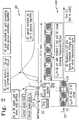
- Figure 1illustrates a preferred excitation signal suitable for use in a system and method, indicated generally at 100, in which DC excitation and four frequencies of AC excitation are used.
- Figure 1also illustrates a typical response to the excitation when the excitation is applied to a sample of whole blood mixed with an appropriate reagent, the response indicated generally at 102.
- a relatively high frequency signalis applied, starting at time 101.
- the frequencyis between about 10kHz and about 20kHz, and has an amplitude between about 12.4mV and about 56.6m V.
- a frequency of 20kHzis used in the example of FIG. 1 .
- Those skilled in the artwill appreciate that these values may be optimised to various parameters such as cell geometry and the particular cell chemistry.
- a test stripis inserted into the meter and several possible responses to the insertion of the test strip into the glucose meter are shown.
- the test stripmay also be inserted before the excitation signal 100 is initiated (i.e. before time 101); however, the test strip itself may advantageously be tested as a control for the suitability of the strip. It is therefore desirable that the excitation signal 100 be initiated prior to test strip insertion.
- relatively large current leakageas shown at 112 may occur if the strip is wet, either because the test strip was pre-dosed, or due to environmental moisture. If the test strip has been pre-dosed and permitted to largely or completely dry out, an intermediate current leakage may occur, as shown at 114.
- insertion of the test stripwill cause no or negligible leakage current due to an expected absence of charge carriers between the test electrodes, as shown at 116.
- Measured current leakage above a predetermined threshold levelwill preferably cause an error message to be displayed and prevent the test from continuing.
- the userdoses the strip, as shown at time 120. While the blood sample is covering the electrodes the current response will rapidly increase, as the glucose reacts with the reagent and the contact area increases to maximum. The response current will reach a stable state, which indicates the impedance of the sample at this frequency.
- the excitation frequencyis then stepped down to about 10kHz, as shown at time 130. Another measurement is made and recorded by the test meter, and the frequency is stepped down to about 2kHz, as shown at 140. A third measurement is made and recorded by the test meter at this frequency. A fourth measurement is made at about 1kHz, as shown at 150. Measurements are taken at regular intervals (e.g.
- the stable state responsemay be measured as current or voltage (preferably both magnitude and phase) and the impedance and/or admittance can be calculated therefrom.
- impedance or admittancemagnitude and/or phase
- resistance, conductivity, current or chargeresistance, conductivity, current or charge
- DC responsecurrent, charge, resistance or conductivity
- measurementsare made at fewer or more frequencies.
- measurementsare made at at least two AC frequencies at least an order of magnitude apart. If more than two AC frequencies are used, then it is preferable that the highest and lowest frequencies be at least an order of magnitude apart.
- AC signalmay be used in an AC signal, including, for example, sinusoidal, trapezoidal, triangle, square and filtered square.
- the AC signalhas a filtered square waveform that approximates a sine wave. This waveform can be generated more economically than a true sine wave, using a square wave generator and one or more filters.
- the signalis preferably briefly reduced to zero amplitude, as shown at 160.
- the DC excitationis then begun, as shown at 170.
- the amplitude of the DC excitationis advantageously selected based on the reagent being used, in order to maximise the resulting response or response robustness. For example, if ferricyanide is being used in a biamperometry system, the DC amplitude is preferably about 300mV. For another example, if a nitrosoaniline derivative is being used in a biamperometry system, the DC amplitude is preferably about 500-550mV.
- the DC applitudeis preferably 600 m V (versus the silver/silver chloride reference electrode) for ferricyanide, and 40-100 mV (versus the silver/silver chloride reference electrode) for nitrosoaniline derivative.
- measurementsare preferably made at a rate of 100 pts/sec.
- the current responsewill follow a decay curve (known as a Cottrell curve), as the reaction is limited by the diffusion of unreacted glucose next to the working electrode.
- the resulting stable-state amplitude(measured or projected) is used to determine a glucose estimation of the sample, as is known in the art.
- a corrected estimationis then determined that corresponds more closely to the concentration of glucose in the blood, by using the impedance of the sample to the AC signal to correct for the effects of interferants, as explained in greater detail hereinbelow.
- a methodmay also be used to measure the concentration of other analytes and in other fluids.
- a methodmay be used to measure the concentration of a medically significant analyte in urine, saliva, spinal fluid, etc.
- a methodmay be adapted to measure the concentration of, for example, lactic acid, hydroxybutyric acid, etc.
- Figure 2illustrates an excitation signal suitable for use in a system and method in which some of the AC and DC components are applied simultaneously, indicated generally at 200, and having corresponding events numbered correspondingly to Figure 1 (so, for example, the signal 200 is initiated at time 201, and a strip is inserted at time 210, etc.).
- the signal 200has a frequency of about 10-20kHz and an amplitude of about 12.4-56.6mV.
- a DC offsetis superimposed, as shown at 270.
- Typical AC and DC responsesare shown in Figure 2 .
- the AC and DC responsesare measured simultaneously and mathematically deconvoluted and used to determine the impedance (admittance magnitude and phase) and the amperometric or coulometric response.
- a system for measuring blood glucoseadvantageously employs a blood glucose meter and test strips generally similar to those used in prior art systems, such as those commercially available from Roche Diagnostics, and such as are described in U.S. Patents Nos. 6,270,637 ; and 5,989,917 .
- These test stripsprovide apparati having a sample cell in which the blood sample is received for testing, and electrodes disposed within the sample cell through which the excitation signal is provided and the measurements are made.
- these test strips and metersmay advantageously be used for the measurement of glucose in blood, but that other apparati may be more suitable for the measurement of other analytes or other biological fluids when practising the present invention.
- a suitable glucose metermay be adapted from such known meters by the addition of electronic circuitry that generates and measures signals having AC and DC components, such as those described hereinabove, and by being programmed to correct the DC measurement using the AC measurement(s), as described in greater detail hereinbelow.
- AC and DC componentssuch as those described hereinabove
- the specific geometry and chemistry of the test stripscan cause variations in the relationships between the concentration of glucose, hematocrit, and temperature, and the impedance of a sample.
- a given combination of test strip geometry and chemistrymust be calibrated, and the meter programmed with the corresponding algorithm.
- excitation signalsmay be in any order and combination, for example, application of 1) AC only, 2) AC then DC, 3) AC then DC then AC, 4) DC then AC, and 5) AC with a DC offset, just to name a few of the possible permutations.
- the processmay never actually arrive at a number equal to the hematocrit value of the sample, but instead determine that the sample's hematocrit differs from a nominal value by a certain amount. Both concepts are intended to be covered by statements such as "determine the hematocrit value.”
- Example 1The measurements made in Example 1 were achieved using the test strip illustrated in Figures 3A-B and indicated generally at 300.
- the test strip 300includes a capillary fill space containing a relatively thick film reagent and working and counter electrodes, as described in U.S. Patent No. 5,997,817 .
- the test strip 300is commercially available from Roche Diagnostics Corporation (Indianapolis, IN) under the brand name Comfort Curve ®.
- the ferricyanide reagent usedhad the composition described in Tables I and II.
- a "dose response" studywas performed, in which glycollyzed (glucose depleted) blood was divided into discrete aliquots and controlled levels of glucose were added to obtain five different known levels of glucose in the blood samples.
- the resulting DC current profilewas then examined as two parameters were varied.
- the first parameterwas the Incubation Time, or the time between the detection of the blood sample being applied to the test strip 300 and the application of the DC potential to the test strip 300.
- the second parameter to be variedwas the Read Time, or the time period after application of the DC potential and the measurement of the resulting current.
- the length of time between detection of the blood sample being applied to the test strip to the taking of the last measurement used in the concentration determination calculationsis the Total Test Time. In this study, therefore, the sum of the Incubation Time and the Read Time is the Total Test Time.
- the results of this studyare illustrated in Figures 5 and 6 .
- the barrier to implementation of such fast test times in a consumer glucose test deviceis the variation from blood sample to blood sample of the level of interference from the presence of blood cells in the sample.
- the hematocrit(the percentage of the volume of a blood sample which is comprised of cells versus plasma) varies from individual to individual.
- the interference effect of hematocrit on such measurementsis fairly complex. In the tests of Example 1, however, all samples contained the same level of hematocrit. With no variable hematocrit influence at the different glucose levels, the hematocrit term cancels out in the correlation figures.
- Example 2Combined AC and DC Measurement of Capillary Blood Samples not according to the present invention
- Example 2The measurements made in Example 2 were also achieved using the test strip illustrated in Figures 3A-B and indicated generally at 300.
- the test strip 300includes a capillary fill space containing a relatively thick film reagent and working and counter electrodes, as described in U.S. Patent No. 5,997,817 .
- capillary blood samples from various fingerstick donorswere applied to test strip 300 and the excitation potentials illustrated in Figure 4 were applied to the electrodes.
- the excitationcomprised a 2 kHz 40 mV rms AC signal applied between 0 seconds and approximately 4.5 seconds after sample application, followed by a 300 mV DC signal applied thereafter.
- the AC response of the samplewas derived as admittance (the inverse of impedance).
- the admittance responseis proportionate to the hematocrit level of the sample in a temperature dependent manner.
- the relationship between admittance, hematocrit and testing temperatureis illustrated in Figure 7 .
- the data used for the admittance charted in Figure 7is the last admittance measurement made for each sample during the AC portion of the excitation illustrated in Figure 4 .
- H estc 0 + c 1 Y 2 kHz + c 2 d T
- c 0 , c 1 and c 2are constants
- d Tis the deviation in temperature from a center defined as “nominal” (24°C for example)
- H estis the estimated deviation in hematocrit from a similar "nominal" value.
- the actual hematocrit valueis not necessary, and it is generally preferred to produce a response which is proportionate but centers around a nominal hematocrit.
- the deviation from a nominal value of 42%would be 28%, while conversely for a 20% hematocrit the deviation from that same nominal value would be -22%.
- Equation 2The constants (a 0 , hct 1 , hct 2 , tau 1 , tau 2 , a 1 , hct 3 , hct 4 , tau 3 and tau 4 ) in Equation 2 can be determined using regression analysis, as is known in the art.
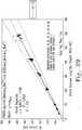
- Figure 8illustrates the uncompensated 5.5 second DC glucose response of all of the capillary blood samples as temperature varies (ignoring the AC measurement data). As will be appreciated, there is a wide variation in the DC current response as temperature and hematocrit vary.
- Figure 9illustrates the correlation between the actual blood glucose level of the sample versus the predicted response using Equation 2. As can be seen, when the DC response is compensated for hematocrit levels using the AC response data, r 2 values of 0.9404 to 0.9605 are achieved with a Total Test Time of 5.5 seconds.
- Example 3Use of AC Phase Angle to Estimate Blood Glucose Levels and Hematocrit not according to the present invention
- Example 3The measurements made in Example 3 were also achieved using the test strip illustrated in Figures 3A-B and indicated generally at 300.
- the test strip 300includes a capillary fill space containing a relatively thick film reagent and working and counter electrodes, as described in U.S. Patent No. 5,997,817 . Because hematocrit levels from capillary blood samples typically vary only between 30% - 50%, spiked venous blood samples having a hematocrit range from 20% - 70% were used for this Example 3. Five levels of glucose, temperature (14, 21, 27, 36 and 42 °C) and hematocrit (20, 30, 45, 60 and 70%) were independently varied, producing a covariance study with 125 samples.
- the excitationcomprised a 2 kHz AC signal for approximately 4.1 seconds, a 1 kHz AC signal for approximately 0.1 seconds, and a 200 Hz signal for approximately 0.1 seconds. All three AC signals had an amplitude of 56.56 mV peak. No DC excitation was used in this example.
- the Total Test Timewas 4.3 seconds from sample application time.
- phase angleis also a function of the sample glucose level in the case of this test strip and reagent.
- the AC excitation frequency producing the measured phase angleis preferably 2 kHz or below, more preferably 1 kHz or below, and most preferably 200 Hz or below, but not including DC excitation.
- the determined coefficientsrevealed that the temperature coefficient (c 3 ) was essentially zero at 20 kHz and 10 kHz, cancelling temperature from the equation at these frequencies. Furthermore, the glucose coefficient (c 1 ) is essentially zero at all of the AC frequencies because, as explained hereinabove, the higher frequency AC impedance measurements are largely unaffected by glucose levels and are therefore useful for measuring the levels of interfering substances. It was therefore found that the hematocrit level could be determined independent of temperature and glucose level using only the AC phase angle measurements.
- the present inventiontherefore may be used to estimate hematocrit using only AC phase angle measurements preferably made at at least one AC frequency, more preferably made at at least two AC frequencies, and most preferably made at at least four AC frequencies.
- Example 4The measurements made in Example 4 were also achieved using the test strip illustrated in Figures 3A-B and indicated generally at 300.
- the test strip 300includes a capillary fill space containing a relatively thick film reagent and working and counter electrodes, as described in U.S .. Patent No. 5,997,817 .
- the test stripwas modified from that described in U.S. Patent No. 5,997,817 , however, by the use of a different reagent.
- the nitrosoaniline reagent usedhad the composition described in Tables III and IV.
- Spiked venous blood sampleswere used. Five levels of glucose, four temperatures (19, 23, 32 and 38 °C) and five levels of hematocrit (20, 30, 45, 60 and 70%) were independently varied, producing a covariance study with 100 samples. 16 test strips 300 were tested for each unique combination of glucose, temperature and hematocrit. The blood samples were applied to test strip 300 and the excitation potentials illustrated in Figure 13 were applied to the electrodes.
- the excitationcomprised a 3.2 kHz AC signal for approximately 4.0 seconds, a 2.13 kHz AC signal for approximately 0.1 seconds, a 1.07 kHz AC signal for approximately 0.1 seconds, a 200 Hz AC signal for approximately 0.1 seconds, a 25 Hz AC signal for approximately 0.1 seconds, followed by a DC signal of 550 mV for approximately 1.0 second. All four AC signals had an amplitude of 56.56 mV peak.
- the Total Test Timewas 5.5 seconds from sample application time.
- the AC response of the samplewas derived as admittance (the inverse of impedance).
- the admittance responseis proportionate to the hematocrit level of the sample in a temperature dependent manner.
- the relationship between admittance, hematocrit and testing temperatureis illustrated in Figure 14 .
- T x HCTcross product term
- H estY 3.2 kHz + c 0 + c 1 d T / c 2 d T + c 3 It was determined that the admittance measurement made at 3.2 kHz was best correlated with hematocrit for this test system. Using this relationship to predict the blood hematocrit is accomplished using test temperature data reported by the temperature sensor in the meter and the measured admittance.
- Equation 7c 0 , c 1 , c 2 and c 3 are constants, d T is the deviation in temperature from a center defined as “nominal” (24°C for example), and H est is the estimated deviation in hematocrit from a similar "nominal" value.
- the actual hematocrit valueis not necessary, and it is generally preferred to produce a response which is proportionate but centers around a nominal hematocrit.
- the deviation from a nominal value of 42%would be 28%, while conversely for a 20% hematocrit the deviation from the same nominal value would be -22%.
- Equation 8can be determined using regression analysis, as is known in the art.
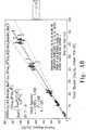
- Figure 15illustrates the uncompensated 5.5 second DC glucose response of all of the blood samples as hematocrit and temperature vary (ignoring the AC measurement data). As will be appreciated, there is a wide variation in the DC current response as temperature and hematocrit vary.
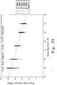
- Figure 16illustrates the correlation between the actual blood glucose level of the sample versus the predicted response using Equation 8. As can be seen, when the DC response is compensated for hematocrit levels using the AC response data, an overall r 2 value of 0.9818 is achieved with a Total Test Time of 5.5 seconds. This demonstrates the applicability of the present invention in achieving high accuracy and fast test times with a different reagent class than was used in Examples 1-3.
- Example 5Combined AC and DC Measurement Using a 0.397 ul Sample not according to the present invention
- test strip 1700comprises a bottom foil layer 1702 formed from an opaque piece of 350 ⁇ m thick polyester (in the preferred embodiment this is Melinex 329 available from DuPont) coated with a 50 nm conductive (gold) layer (by sputtering or vapor deposition, for example). Electrodes and connecting traces are then patterned in the conductive layer by a laser ablation process to form working, counter, and dose sufficiency electrodes (described in greater detail hereinbelow) as shown.
- Melinex 329available from DuPont
- the laser ablation processis performed by means of an excimer laser which passes through a chrome-on-quartz mask.
- the mask patterncauses parts of the laser field to be reflected while allowing other parts of the field to pass through, creating a pattern on the gold which is ejected from the surface where contacted by the laser light.
- the bottom foil layer 1702is then coated in the area extending over the electrodes with a reagent layer 1704 in the form of an extremely thin reagent film.
- This procedureplaces a stripe of approximately 7 .2 millimeters width across the bottom foil 1702 in the region labelled "Reagent Layer" on Figure 17 .
- this regionis coated at a wet-coat weight of 50 grams per square meter of coated surf ace area leaving a dried reagent less than 20 ⁇ m thick.
- the reagent stripeis dried conventionally with an in-line drying system where the nominal air temperature is at 110°C. The rate of processing is nominally 30-38 meters per minute and depends upon the rheology of the reagent.
- the materialsare processed in continuous reels such that the electrode pattern is orthogonal to the length of the reel, in the case of the bottom foil 1702.
- the spaceris slit and placed in a reel-to-reel process onto the bottom foil 1702.
- Two spacers 1706 formed from 100 ⁇ m polyester (in the preferred embodiment this is Melinex 329 available from DuPont) coated with 25 ⁇ m PSA (hydrophobic adhesive) on both the dorsal and ventral surfacesare applied to the bottom foil layer 1702, such that the spacers 1706 are separated by 1.5 mm and the working, counter and dose sufficiency electrodes are centered in this gap.
- the hydrophilic filmis coated with a mixture of Vitel and Rhodapex surfactant at a nominal thickness of 10 microns.
- the top foil layer 1708is laminated using a reel-to-reel process. The sensors can then be produced from the resulting reels of material by means of slitting and cutting.
- the 1.5 mm gap in the spacers 1706therefore forms a capillary fill space between the bottom foil layer 1702 and the top foil layer 1708.
- the distance from the sample application port 1710 and the dose sufficiency electrodesis 1.765 mm.
- the volume of sample needed to sufficiently cover the working, counter and dose sufficiency electrodesi.e. the minimum sample volume necessary for a measurement
- 1.5 mm ⁇ 1.765 mm ⁇ 0.15 mm1.397 ⁇ l
- the reagent composition for the test strip 1700is given in Tables V and VI.
- Table VReagent Mass Composition - Prior to Dispense and Drying Component % w/w Mass for 1kg solid Polyethylene oxide (300kDa) 1.0086% 10.0855g solid Natrosol 250M 0.3495% 3.4954g solid Carboxymethylcellulose 7HF 0.3495% 3.4954g solid Monobasic potassium phosphate (annhydrous) 0.9410% 9.4103g solid Dibasic potassium phosphate (trihydrous) 1.6539% 16.5394g solid Disodium Succinate hexahydrate 0.2852% 2.8516g solid Potassium Hydroxide 0.2335% 2.3351g solid Quinoprotein glucose dehydrogenase (EnzC#: 1.1.99.17) 0.3321% 3.3211g solid PQQ 0.0093% 0.0925g solid Trehalose 0.7721% 7.7210g solid Mediator 31.1144 0.6896% 6.8956g solid Triton X-
- a protocol for the preparation of the preferred nitrosoaniline reagentis as follows:
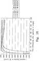
- the measurement results illustrated in FIG. 18show the correlation coefficient r 2 between the DC current response and the glucose level as the Read Time varies for three combinations of temperature and hematocrit. These results demonstrate that a robust DC response should be anticipated for tests as fast as 1 second. However, those skilled in the art will recognise that there are undesirable variations in the sensor accuracy (correlation) due to the interfering effects of temperature and hematocrit levels, suggesting that the combined AC and DC measurement method should produce more closely correlated results.
- the excitationcomprised a 10 kHz AC signal applied for approximately 1.8 seconds, a 20 kHz AC signal applied for approximately 0.2 seconds, a 2 Hz AC signal applied for approximately 0.2 seconds, a 1Hz AC signal applied for approximately 0.2 seconds, and a DC signal applied for approximately 0.5 seconds.
- the AC signalshad an amplitude of 12.7 mV peak, while the DC signal had an amplitude of 550 mV.
- the Total Test Timewas 3.0 seconds.
- phase angle of the 20 kHz AC responseis plotted versus hematocrit in Figure 21 .
- the results for phase angle measured at 10 kHzare similar.
- the correlation between phase angle and hematocritwas better at higher frequencies. Because of this, the c 2 constant approaches zero and H est can reliably be estimated using only the 10 kHz and 20 kHz data. Use of lower frequencies, however, allows for slight improvements in the strip-to-strip variability of the H est function.
- the exampletherefore may be used to estimate hematocrit using only AC phase angle measurements preferably made at at least one AC frequency, more preferably made at at least two AC frequencies, and most preferably made at at least four AC frequencies.
- test strip geometries and dimensionsThe particular frequencies that produce the most robust results will be determined by test strip geometries and dimensions.
- the exampletherefore may be used to estimate test sample temperature using only AC response measurements preferably made at at least one AC frequency, more preferably made at at least two AC frequencies, and most preferably made at at least four AC frequencies.
- the direct measurement of the temperature of the sample under testis a great improvement over prior art methods for estimating the temperature of the sample.
- a thermistoris placed in the test meter near where the test strip is inserted into the meter. Because the thermistor is measuring a temperature remote from the actual sample, it is at best only a rough approximation of the true sample temperature. Furthermore, if the sample temperature is changing (for example due to evaporation), then the thermal inertia of the test meter and even the thermistor itself will prevent the meter-mounted thermistor from accurately reflecting the true temperature of the sample under test.
- the temperature estimationis derived from measurements made within the sample under test (i.e. within the reaction zone in which the sample under test reacts with the reagent), thereby eliminating any error introduced by the sample being remote from the measuring location.
- the temperature estimation of the present inventionis made using data that was collected very close in time to the glucose measurement data that will be corrected using the temperature estimation, thereby further improving accuracy. This represents a significant improvement over the prior art methods.
- Equation 13the constants in Equation 13 can be determined using regression analysis, as is known in the art.
- the present inventiontherefore allows one to estimate hematocrit by using the AC phase angle response (Equation 11).
- the estimated hematocrit and the measured AC admittancecan be used to determine the estimated temperature (Equation 12).
- the estimated hematocrit and estimated temperaturecan be used with the measured DC response to obtain the predicted glucose concentration (Equation 13).
- the excitation profile illustrated in Figure 24was utilized in order to decrease the Total Test Time. As described above with respect to Example 5, it was determined that the phase angle at 20 kHz and at 10 kHz were most closely correlated with the hematocrit estimation. It was therefore decided to limit the AC portion of the excitation to these two frequencies in Example 6 in order to decrease the Total Test Time. In order to make further reductions in Total Test Time, the 10 kHz AC excitation was applied simultaneously with the DC signal (i.e. an AC signal with a DC offset), the theory being that this combined mode would allow for the collection of simultaneous results for DC current, AC phase and AC admittance, providing the fastest possible results. Therefore, the 20 kHz signal was applied for 0.9 seconds. Thereafter, the 10 kHz and DC signals were applied simultaneously for 1.0 second after a 0.1 second interval.
- the DC signali.e. an AC signal with a DC offset
- Example 649 spiked venous blood samples representing seven glucose levels and seven hematocrit levels were tested.
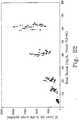
- the correlation coefficient r 2 between the DC current and the blood hematocritwas then examined at three DC measurement times: 1.1 seconds, 1.5 seconds and 1.9 seconds after sample application. These correlations are plotted versus hematocrit level in Figure 25 . All of these results are comparable, although the correlation is generally poorest at 1.1 seconds and generally best at 1.5 seconds. The minimum correlation coefficient, however, exceeds 0.99.
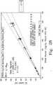
- Figure 26illustrates the phase angle at 20 kHz plotted against hematocrit levels.
- the correlation between these two sets of datais very good, therefore it was decided that the 10 kHz data was unnecessary for estimating hematocrit.
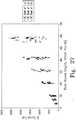
- Figure 27illustrates the DC current response versus glucose level for all measured hematocrit levels as the read time is varied between 1.1 seconds, 1.5 seconds and 1.9 seconds. Not surprisingly, the DC current at 1.1 seconds is greater than the DC current at 1.5 seconds, which is greater than the DC current at 1.9 seconds. Those skilled in the art will recognise that the hematocrit level has a large effect on the DC current, particularly at high glucose concentrations.
- Equation 15does not include temperature compensation terms since temperature variation was not included in the experiment of this Example 6, it can be reasonably inferred from previous examples that a Test term could be included using the 10 kHz and 20 kHz admittance values in combination with the H est term.
- the hematocrit compensated predicted glucose responsecan be determined using only this phase angle information and the measured DC response.
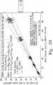
- the compensated DC response versus glucose level for only the DC read at 1.1 seconds(representing a 1.1 second Total Test Time) is illustrated in Figure 28 .
- the datashows an overall r 2 correlation of 0.9947 with a 1.1 second Total Test Time.
- Example 7Use of AC Phase Angle to Detect an Abused Sensor not according to the present invention
- Cottrell Failsafe RatioCFR
- I cottrellnFA D ⁇ Ct ⁇
- a Current Sum Failsafecan be devised that places a check on the Cottrell response of the sensor by summing all of the acquired currents during sensor measurement. When the final current is acquired, it is multiplied by two constants (which may be loaded into the meter at the time of manufacture or, more preferably, supplied to the meter with each lot of sensors, such as by a separate code key or by information coded onto the sensor itself). These constants represent the upper and lower threshold for allowable NCFR values.
- the two products of the constants multiplied by the final currentare compared to the sum of the biosensor currents.
- the sum of the currentsshould fall between the two products, thereby indicating that the ratio above was fulfilled, plus or minus a tolerance.
- MCFRModified Cottrell Failsafe Ratio
- the NCFR(and MCFR) is correlated with hematocrit.
- the AC phase angleis also correlated with hematocrit. It follows then, that the AC phase angle and the NCFR are correlated with one another. This relationship holds only if the sensor is unabused. The correlation degrades for an abused sensor.
- the intercept term fs 0can be chosen such that a FAILSAFE value below zero indicates an abused sensor, while a FAILSAFE value above zero indicates a non-abused sensor.
- Another problem with prior art dose sufficiency methodologies determined by the present inventorsrelates to the use of one or the other of the available measurement electrodes in electrical communication with an upstream or downstream dose detection electrode.
- the stoichiometry of the measurement zone(the area above or between the measurement electrodes) is perturbed during the dose detect/dose sufficiency test cycle prior to making a measurement of the analyte of interest residing in the measurement zone.
- sample matricesvary radically in make-up, the fill properties of these samples also vary, resulting in timing differences between sample types.
- Such erratic timing routinesact as an additional source of imprecision and expanded total system error metrics.
- Example 8Determination of Fluid Flow Front Behavior in a Capillary Fill Space
- test fixturescomprising two sheets of clear polycarbonate sheets joined together with double-sided adhesive tape were used, where the capillary fill space was formed by cutting a channel in the double-sided tape. Use of the polycarbonate upper and lower sheets allowed the flow fronts of the sample to be videotaped as it flowed through the capillary fill space.
- test deviceswere laminated using laser cut 1mm thick Lexan® polycarbonate sheets (obtained from Cadillac Plastics Ltd., Westlea, Swindon SN5 7EX, United Kingdom).
- the top and bottom polycarbonate sheetswere coupled together using double-sided adhesive tapes (#200MP High Performance acrylic adhesive obtained from 3M Corporation, St. Paul, MN).
- the capillary channelswere defined by laser cutting the required width openings into the double-sided tape. Tape thicknesses of 0.05 ⁇ m, 0.125 ⁇ m, and 0.225 ⁇ m were used to give the required channel heights.
- the dimensions of the capillary spaces of the test devicesare tabulated in FIG. 31 .
- top and bottom polycarbonate partswere laminated together with the laser cut adhesive tapes using a custom-built jig to ensure reproducible fabrication.
- a fluid receptor regiondefineing the entrance to the capillary channel was formed by an opening pre-cut into the upper polycarbonate sheet and adhesive tape components.
- channel widths0.5mm, 1.00mm, 1.5mm, 2.00mm, 3.00mm, and 4.00mm were fabricated.
- the capillary channel length for all deviceswas 50mm. Twenty-eight (28) of each of the eighteen (18) device types were constructed.
- the assembled deviceswere plasma treated by Weidman Plastics Technology of Dortmund, Germany. The following plasma treatment conditions were used:
- Each of the test deviceswas dosed with a fixed volume of venous blood having a hematocrit value of 45%.
- Flow and flow front behaviorwas captured on videotape for later analysis. It was determined that the relative dimensions of the capillary fill channel determined the flow front behavior.
- Devices to the left of the dashed line in FIG. 31(devices A2, A4, B2, B4, B5, C2, C4, and C5) resulted in a convex flow front behavior, while devices to the right of the dashed line (devices A6, A8, A11, B6, B8, B11, C6, C8, and C11) displayed a concave flow front behavior.
- Both the convex and concave flow front behaviorsare schematically illustrated in FIG. 31 . This data shows that the aspect ratio between the height and the width of the capillary fill space is a determining factor in whether the sample flow front is convex or concave.
- FIGs. 32A-CThe problems associated with a concave flow front in a capillary fill space are illustrated in FIGs. 32A-C .
- the test stripincludes a working electrode 3200, a reference electrode 3202, and a downstream dose sufficiency electrode 3204 that works in conjunction with one of the measurement electrodes 3200 or 3202.
- FIGs. 32A-Cillustrate that a sample flow front exhibiting a concave shape can also cause biased measurement results. In each drawing, the direction of sample travel is shown by the arrow. In FIG.
- the portions of the sample adjacent to the capillary wallshave reached the dose sufficiency electrode 3204, thereby electrically completing the DC circuit between this electrode and one of the measurement electrode pair that is being monitored by the test meter in order to make the dose sufficiency determination.
- the test meterwill conclude that there is sufficient sample to make a measurement at this time, the sample clearly has barely reached the reference electrode 3202 and any measurement results obtained at this time will be highly biased.
- FIG. 32Billustrates the situation where the dose sufficiency electrode 3204 has been contacted (indicating that the measurement should be started), but the reference electrode 3202 is only partially covered by the sample. Although the sample has reached the reference electrode 3202 at this time, the reference electrode 3202 is not completely covered by sample, therefore any measurement results obtained at this time will be partially biased. Both of the situations illustrated in FIGs. 32A-B will therefore indicate a false positive for dose sufficiency, thereby biasing the measurement test results. Only in the situation illustrated in FIG. 32C , where the reference electrode 3202 is completely covered by the sample, will the measurement results be unbiased due to the extent of capillary fill in the measurement zone.
- the present inventionsolves the stoichiometric problems associated with the prior art designs pairing the dose sufficiency electrode with one of the measurement electrodes when making the dose sufficiency determination.
- the present inventioncomprehends a test strip having an independent pair of dose sufficiency electrodes positioned downstream from the measurement electrodes.
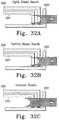
- the test stripis indicated generally as 3300, and includes a measurement electrode pair consisting of a counter electrode 3302 and a working electrode 3304.
- the electrodesmay be formed upon any suitable substrate in a multilayer test strip configuration as is known in the art and described hereinabove.
- the multilayer configuration of the test stripprovides for the formation of a capillary fill space 3306, also as known in the art.
- a dose sufficiency working electrode 3308 and a dose sufficiency counter electrode 3310are formed within the capillary fill space 3306, and downstream (relative to the direction of sample flow) from the measurement electrodes 3302 and 3304.
- the test meterWhen the test strip 3300 is inserted into the test meter, the test meter will continuously check for a conduction path between the dose sufficiency electrodes 3308 and 3310 in order to determine when the sample has migrated to this region of the capillary fill space. Once the sample has reached this level, the test meter may be programmed to conclude that the measurement electrodes are covered with sample and the sample measurement sequence may be begun. It will be appreciated that, unlike as required with prior art designs, no voltage or current need be applied to either of the measurement electrodes 3302 and 3304 during the dose sufficiency test using the test strip design of FIG. 33 .
- the stoichiometry of the measurement zoneis not perturbed during the dose sufficiency test cycle prior to making a measurement of the analyte of interest residing in the measurement zone. This represents a significant improvement over the dose sufficiency test methodologies of the prior art.
- the test strip 3300is also desirable for judging dose sufficiency when the capillary fill space is designed to produce samples that exhibit a convex flow front while filling the capillary fill space 3306, as illustrated in FIG. 34A .
- the measurement zone above the measurement electrodes 3302 and 3304is covered with sample when the convex flow front reaches the dose sufficiency electrode pair 3308,3310.
- the test strip design 3300may not, however, produce ideal results if the capillary fill space 3306 allows the sample to exhibit a concave flow front while filling, as shown in FIG. 34B .
- the peripheral edges of the concave flow frontreach the dose sufficiency electrodes 3308,3310 before the measurement zone has been completely covered with sample.
- the dose sufficiency electrodes 3308,3310will indicate sample sufficiency as soon as they are both touched by the edges of the flow front. Therefore, the dose sufficiency electrode design shown in the test strip of FIG. 33 works best when the sample filling the capillary space 3306 exhibits a convex flow front. Furthermore, multiple pairs of dose sufficiency electrodes may be provided, each at a different distance from the measurement zone, such that the capability to assess the extent of capillary space 3306 filling may be provided by examining which of the multiple pairs of dose sufficiency electrodes has been bridged by the sample.
- the dose sufficiency electrodes 3308,3310have their longest axis within the capillary fill space 3306 oriented perpendicular to the longitudinal axis of the capillary fill space 3306. Such electrodes are referred to herein as "perpendicular dose sufficiency electrodes.”
- An alternative dose sufficiency electrode arrangementis illustrated in FIGs. 35A-B .
- the present inventionalso comprehends a test strip having an independent pair of dose sufficiency electrodes positioned downstream from the measurement electrodes, where the dose sufficiency electrodes have their longest axis within the capillary fill space oriented parallel to the longitudinal axis of the capillary fill space.
- the test strip in FIG. 35is indicated generally as 3500, and includes a measurement electrode pair consisting of a counter electrode 3502 and a working electrode 3504.
- the electrodesmay be formed upon any suitable substrate in a multilayer test strip configuration as is known in the art and described hereinabove.
- the multilayer configuration of the test stripprovides for the formation of a capillary fill space 3506, also as known in the art.
- a dose sufficiency working electrode 3508 and a dose sufficiency counter electrode 3510together forming a parallel dose sufficiency electrode pair.
- the test meterWhen the test strip 3500 is inserted into the test meter, the test meter will continuously check for a conduction path between the dose sufficiency electrodes 3508 and 3510 in order to determine when the sample has migrated to this region of the capillary fill space. Once the sample has reached this level, the test meter may be programmed to conclude that the measurement electrodes are covered with sample and the sample measurement sequence may be begun. It will be appreciated that, as with the test strip 3300 (and unlike as required with prior art designs), no voltage or current need be applied to either of the measurement electrodes 3502 and 3504 during the dose sufficiency test using the test strip design of FIG. 35 .
- the stoichiometry of the measurement zoneis not perturbed during the dose sufficiency test cycle prior to making a measurement of the analyte of interest residing in the measurement zone. This represents a significant improvement over the dose sufficiency test methodologies of the prior art.
- a further improved operationis realized with the parallel dose sufficiency electrodes of the test strip 3500 when the dose sufficiency electrodes are energized with a relatively high frequency AC excitation signal.
- the dose sufficiency electrodes 3508,3510display significant edge effects, wherein the excitation signal traverses the gap between the electrodes only when the electrode edges along the gap are covered with the sample fluid.
- the test strip 3500is illustrated in enlarged size in FIG. 36 (with only the electrode portions lying within the capillary fill space 3506 and the strip-to-meter electrode contact pads visible).
- the gap width GW between the edges of the dose sufficiency electrodes 3508,3510is preferably 100-300 ⁇ m, more preferably 150-260 ⁇ m, and most preferably 255 ⁇ m.
- a smaller gap width GWincreases the amount of signal transmitted between dose sufficiency electrodes whose edges are at least partially covered by sample; however, the capacitance of the signal transmission path increases with decreasing gap width GW.
- An advantage of the parallel dose sufficiency electrode design of FIGs. 35 and 36when used with AC excitation, is that there is substantially no electrical communication between the electrodes until the sample covers at least a portion of the edges along the electrode gap. Therefore, a sample exhibiting the concave flow front of FIG. 35A , where the illustrated sample is touching both of the dose sufficiency electrodes 3508,3510 but is not touching the electrode edges along the gap, will not produce any significant electrical communication between the dose sufficiency electrodes. The test meter will therefore not form a conclusion of dose sufficiency until the sample has actually bridged the dose sufficiency electrodes between the electrode edges along the gap.
- Another advantage to the parallel dose sufficiency electrodes illustrated in FIGs. 35 and 36is that the amount of signal transmitted between the electrodes is proportional to the amount of the gap edges that is covered by the sample. By employing an appropriate threshold value in the test meter, a conclusion of dose sufficiency can therefore be withheld until the sample has covered a predetermined portion of the dose sufficiency electrode gap edge. Furthermore, an analysis of the dose sufficiency signal will allow the test meter to record the percentage of fill of the capillary fill space for each measurement made by the test meter, if desired.
- DC responseshave the problems of being sensitive to variations in, for example, temperature, hematocrit and the analyte (glucose for example).
- AC responses at sufficiently high frequencycan be made robust to the variation in the analyte concentration.
- the AC response generated at sufficiently high frequencies in such capillary fill devicesis primarily limited by the amount of the parallel gap between the electrode edges which is filled by the sample.
- the senorcan be made more or less sensitive as is deemed advantageous, with a higher threshold for admittance requiring more of the parallel gap to be filled before test initiation.
- a further limitation of existing devicesis the inability of the electrode geometry to discern the amount of time needed to fill the capillary space of the sensor. This limitation is caused by having interdependence of the dose sufficiency electrode and the measurement electrodes. This is a further advantage of independent dose sufficiency electrodes.
- a signalis first applied across the measurement electrodes prior to dosing. When a response is observed, the potential is immediately switched off and a second signal is applied across the dose sufficiency electrodes during which time the system both looks for a response to the signal (indicating electrode coverage) and marks the duration between the first event (when a response is observed at the measurement electrodes) and the second event (when a response is observed at the dose sufficiency electrodes).
Landscapes
- Health & Medical Sciences (AREA)
- Chemical & Material Sciences (AREA)
- Hematology (AREA)
- Life Sciences & Earth Sciences (AREA)
- Electrochemistry (AREA)
- Chemical Kinetics & Catalysis (AREA)
- Molecular Biology (AREA)
- Physics & Mathematics (AREA)
- Analytical Chemistry (AREA)
- Biochemistry (AREA)
- General Health & Medical Sciences (AREA)
- General Physics & Mathematics (AREA)
- Immunology (AREA)
- Pathology (AREA)
- Investigating Or Analysing Biological Materials (AREA)
Description
- The present invention relates to a method of determining a fill sufficiency or a dosage fill level or a dosage fill rate in a test strip for performing a measurement on a biological fluid.
- Measuring the concentration of substances, particularly in the presence of other, confounding substances, is important in many fields, and especially in medical diagnosis. For example, the measurement of glucose in body fluids, such as blood, is crucial to the effective treatment of diabetes.
- Diabetic therapy typically involves two types of insulin treatment: basal, and meal-time. Basal insulin refers to continuous, e.g. time-released insulin, often taken before bed. Meal-time insulin treatment provides additional doses of faster acting insulin to regulate fluctuations in blood glucose caused by a variety of factors, including the metabolization of sugars and carbohydrates. Proper regulation of blood glucose fluctuations requires accurate measurement of the concentration of glucose in the blood. Failure to do so can produce extreme complications, including blindness and loss of circulation in the extremities, which can ultimately deprive the diabetic of use of his or her fingers, hands, feet, etc.
- Multiple methods are known for measuring the concentration of analytes in a blood sample, such as, for example, glucose. Such methods typically fall into one of two categories: optical methods and electrochemical methods. Optical methods generally involve reflectance or absorbance spectroscopy to observe the spectrum shift in a reagent. Such shifts are caused by a chemical reaction that produces a color change indicative of the concentration of the analyte. Electrochemical methods generally involve, alternatively, amperometric or coulometric responses indicative of the concentration of the analyte. See, for example,
U.S. Patent Nos. 4,233,029 to Columbus ,4,225,410 to Pace ,4,323,536 to Columbus ,4,008,448 to Muggli ,4,654,197 to Lilja et al. ,5,108,564 to Szuminsky et al. ,5,120,420 to Nankai et al. ,5,128,015 to Szuminsky et al. ,5,243,516 to White ,5,437,999 to Diebold et al. ,5,288,636 to Pollmann et al. ,5,628,890 to Carter et al. ,5,682,884 to Hill et al. ,5,727,548 to Hill et al. ,5,997,817 to Crismore et al. ,6,004,441 to Fujiwara et al. ,4,919,770 to Priedel, et al. , and6,054,039 to Shieh . - An important limitation of electrochemical methods of measuring the concentration of a chemical in blood is the effect of confounding variables on the diffusion of analyte and the various active ingredients of the reagent. For example, the geometry and state of the blood sample must correspond closely to that upon which the signal-to-concentration mapping function is based.
- The geometry of the blood sample is typically controlled by a sample-receiving portion of the testing apparatus. In the case of blood glucose meters, for example, the blood sample is typically placed onto a disposable test strip that plugs into the meter. The test strip may have a sample chamber (capillary fill space) to define the geometry of the sample. Alternatively, the effects of sample geometry may be limited by assuring an effectively infinite sample size. For example, the electrodes used for measuring the analyte may be spaced closely enough so that a drop of blood on the test strip extends substantially beyond the electrodes in all directions. Ensuring adequate coverage of the measurement electrodes by the sample, however, is an important factor in achieving accurate test results. This has proven to be problematic in the past, particularly with the use of capillary fill spaces.
WO 99/32881 EP 0471986 discloses a sensor comprising a capillary fill chamber with two sufficiency electrodes positioned therein to define a gap between one another.WO 02/054055 - Other examples of limitations to the accuracy of blood glucose measurements include variations in blood composition or state (other than the aspect being measured). For example, variations in hematocrit (concentration of red blood cells), or in the concentration of other chemicals in the blood, can effect the signal generation of a blood sample. Variations in the temperature of blood samples is yet another example of a confounding variable in measuring blood chemistry.
- Thus, a method is needed to ensure adequate coverage of the measurement electrodes by the sample, particularly in capillary fill devices. It is an object of the present invention to provide such a method.
- The present invention is as defined in the claims.
Fig. 1 is a diagram of an excitation signal suitable for use in a method according to the present invention, having a serially-applied AC component and DC component.Fig. 2 is a diagram of an excitation signal suitable for use in a method according to the present invention, having a simultaneously-applied AC component and DC component.Figs. 3A-B illustrate a test strip.Fig. 4 is a diagram of an excitation signal utilized in the test of Example 1.Fig. 5 is a plot of the correlation coefficient r2 (glucose vs. DC current) versus Read Time for the test of Example 1 with no incubation time.Fig. 6 is a plot of the correlation coefficient r2 (glucose vs. DC current) versus Read Time for the test of Example 1 with varying incubation time.Fig. 7 is a plot of AC admittance versus hematocrit for the test of Example 2.Fig. 8 is a plot of uncompensated DC current versus glucose for the test of Example 2.Fig. 9 is a plot of the predicted glucose response versus the actual glucose response for the test of Example 2.Fig. 10 is a diagram of an excitation signal utilized in the test of Example 3.Fig. 11 is a plot of the AC phase angle versus reference glucose for the test of Example 3.Fig. 12 is a plot of the predicted glucose response versus the actual glucose response for the test of Example 3.Fig. 13 is a diagram of an excitation signal utilized in the test of Example 4.Fig. 14 is a plot of AC admittance versus hematocrit (parametrically displayed with temperature) for the test of Example 4.Fig. 15 is a plot of the uncompensated DC response versus actual glucose for the test of Example 4.Fig. 16 is a plot of the predicted glucose response versus actual glucose response for the test of Example 4.Figs. 17 A-B illustrate a test strip.Fig. 18 is a plot parametrically illustrating the correlation coefficient r2 between the DC current response and glucose level as Read Time varies for three combinations of temperature and hematocrit in the test of Example 5.Fig. 19 is a diagram of the excitation signal utilized in the test of Example 5.Fig. 20 is a plot of AC admittance versus hematocrit as temperature is parametrically varied in the test of Example 5.Fig. 21 is a plot of AC admittance phase angle versus hematocrit as temperature is parametrically varied in the test of Example 5.Fig. 22 is a plot of the uncompensated DC response versus actual glucose for the test of Example 5.Fig. 23 is a plot of the predicted glucose response versus actual glucose response for the test of Example 5.Fig. 24 is a diagram of the excitation signal utilized in the test of Example 6.Fig. 25 is a plot of the correlation coefficient r2 between hematocrit and DC response current plotted against hematocrit in the test of Example 6.Fig. 26 is a plot of AC admittance phase angle versus hematocrit for the test of Example 6.Fig. 27 is a plot of the uncompensated DC response versus actual glucose for the test of Example 6.Fig. 28 is a plot of the compensated DC response versus actual glucose for a 1.1 second Total Test Time of Example 6.Fig. 29 is a plot of the compensated DC response versus actual glucose for a 1.5 second Total Test Time of Example 6.Fig. 30 is a plot of the compensated DC response versus actual glucose for a 1.9 second Total Test Time of Example 6.Fig. 31 is a table detailing the heights and widths of the capillary fill channels used in the test devices of Example 8, as well as schematic diagrams of convex and concave sample flow fronts in a capillary fill space.Figs. 32A-C are schematic plan views of a test strip illustrating the potential for biased measurement results when a concave flow front encounters a prior art dose sufficiency electrode.Fig. 33 is a schematic plan view of a test strip of the present invention having a pair of perpendicular dose sufficiency electrodes that are independent from the measurement electrodes.Figs. 34A-B are schematic plan views of the test strip ofFIG. 33 containing samples with convex and concave flow fronts, respectively.Figs. 35A-B are schematic plan views of a test strip of the present invention having a pair of parallel dose sufficiency electrodes that are independent from the measurement electrodes.Fig. 36 is a schematic plan view of the test strip ofFig. 35 , schematically illustrating the electric field lines that communicate between the electrode gap when the electrodes are covered with sample.- A system and method permit the accurate measurement of an analyte in a fluid. In particular, the measurement of the analyte remains accurate despite the presence of interferants, which would otherwise cause error. For example, a blood glucose meter measures the concentration of blood glucose without error that is typically caused by variations in the temperature and the hematocrit level of the sample. The accurate measurement of blood glucose is invaluable to the prevention of blindness, loss of circulation, and other complications of inadequate regulation of blood glucose in diabetics. An additional advantage of a system and method is that measurements can be made much more rapidly and with much smaller sample volumes, making it more convenient for the diabetic person to measure their blood glucose. Likewise, accurate and rapid measurement of other analytes in blood, urine, or other biological fluids provides for improved diagnosis and treatment of a wide range of medical conditions.
- It will be appreciated that electrochemical blood glucose meters typically (but not always) measure the electrochemical response of a blood sample in the presence of a reagent. The reagent reacts with the glucose to produce charge carriers that are not otherwise present in blood. Consequently, the electrochemical response of the blood in the presence of a given signal is intended to be primarily dependent upon the concentration of blood glucose. Secondarily, however, the electrochemical response of the blood to a given signal is dependent upon other factors, including hematocrit and temperature. See, for example,
U.S. Patents Nos. 5,243,516 ;5,288,636 ;5,352,351 ;5,385,846 ; and5,508,171 , which discuss the confounding effects of hematocrit on the measurement of blood glucose. In addition, certain other chemicals can influence the transfer of charge carriers through a blood sample, including, for example, uric acid, bilirubin, and oxygen, thereby causing error in the measurement of glucose. - A preferred system and method for measuring blood glucose operates generally by using the signal-dependence of the contribution of various factors to the impedance (from which admittance and phase angle may be derived) of a blood sample. Because the contribution of various factors to the impedance of a blood sample is a function of the applied signal, the effects of confounding factors (that is, those other than the factors sought to be measured) can be substantially reduced by measuring the impedance of the blood sample to multiple signals. In particular, the effects of confounding factors, (primarily temperature and hematocrit, but also including chemical interferants such as oxygen), contribute primarily to the resistivity of the sample, while the glucose-dependent reaction contributes primarily to the capacitance. Thus, the effects of the confounding factors can be eliminated by measuring the impedance of the blood sample to an AC excitation, either alone or in combination with a DC excitation. The impedance (or the impedance derived admittance and phase information) of the AC signal is then used to correct the DC signal or AC derived capacitance for the effects of interferants.
- It will be appreciated that measurements at sufficiently high AC frequencies are relatively insensitive to the capacitive component of the sample's impedance, while low frequency (including DC) measurements are increasingly (with decreasing frequency) sensitive to both the resistive and the capacitive components of the sample's impedance. The resistive and capacitive components of the impedance can be better isolated by measuring the impedance at a larger number of frequencies. However, the cost and complexity of the meter increases as the number of measurements increases and the number of frequencies that need to be generated increases. Thus, in the presently preferred embodiment, the impedance may be measured at greater than ten frequencies, but preferably at between two and ten frequencies, and most preferably at between two and five frequencies.
- As used herein, the phrase "a signal having an AC component" refers to a signal which has some alternating potential (voltage) portions. For example, the signal may be an "AC signal" having 100% alternating potential (voltage) and no DC portions; the signal may have AC and DC portions separated in time; or the signal may be AC with a DC offset (AC and DC signals superimposed).
Figure 1 illustrates a preferred excitation signal suitable for use in a system and method, indicated generally at 100, in which DC excitation and four frequencies of AC excitation are used.Figure 1 also illustrates a typical response to the excitation when the excitation is applied to a sample of whole blood mixed with an appropriate reagent, the response indicated generally at 102. A relatively high frequency signal is applied, starting attime 101. In the preferred embodiment the frequency is between about 10kHz and about 20kHz, and has an amplitude between about 12.4mV and about 56.6m V. A frequency of 20kHz is used in the example ofFIG. 1 . Those skilled in the art will appreciate that these values may be optimised to various parameters such as cell geometry and the particular cell chemistry.- At time 110 a test strip is inserted into the meter and several possible responses to the insertion of the test strip into the glucose meter are shown. It will be appreciated that the test strip may also be inserted before the
excitation signal 100 is initiated (i.e. before time 101); however, the test strip itself may advantageously be tested as a control for the suitability of the strip. It is therefore desirable that theexcitation signal 100 be initiated prior to test strip insertion. For example, relatively large current leakage, as shown at 112, may occur if the strip is wet, either because the test strip was pre-dosed, or due to environmental moisture. If the test strip has been pre-dosed and permitted to largely or completely dry out, an intermediate current leakage may occur, as shown at 114. Ideally, insertion of the test strip will cause no or negligible leakage current due to an expected absence of charge carriers between the test electrodes, as shown at 116. Measured current leakage above a predetermined threshold level will preferably cause an error message to be displayed and prevent the test from continuing. - Once a suitable test strip has been inserted, the user doses the strip, as shown at
time 120. While the blood sample is covering the electrodes the current response will rapidly increase, as the glucose reacts with the reagent and the contact area increases to maximum. The response current will reach a stable state, which indicates the impedance of the sample at this frequency. Once this measurement is made and recorded by the test meter, the excitation frequency is then stepped down to about 10kHz, as shown attime 130. Another measurement is made and recorded by the test meter, and the frequency is stepped down to about 2kHz, as shown at 140. A third measurement is made and recorded by the test meter at this frequency. A fourth measurement is made at about 1kHz, as shown at 150. Measurements are taken at regular intervals (e.g. 10 points per cycle). It will be appreciated that the stable state response may be measured as current or voltage (preferably both magnitude and phase) and the impedance and/or admittance can be calculated therefrom. Although it is referred herein alternately to the AC response as impedance or admittance (magnitude and/or phase), resistance, conductivity, current or charge, and to the DC response as current, charge, resistance or conductivity, those skilled in the art will recognize that these measures are interchangeable, it only being necessary to adjust the measurement and correction mathematics to account for which measure is being employed. The preferred test meter applies a voltage to one electrode and measures the current response at the other electrode to obtain both the AC and DC response. - In certain alternative measurements are made at fewer or more frequencies. Preferably measurements are made at at least two AC frequencies at least an order of magnitude apart. If more than two AC frequencies are used, then it is preferable that the highest and lowest frequencies be at least an order of magnitude apart.
- It will be appreciated that various waveforms may be used in an AC signal, including, for example, sinusoidal, trapezoidal, triangle, square and filtered square. In the presently preferred embodiment the AC signal has a filtered square waveform that approximates a sine wave. This waveform can be generated more economically than a true sine wave, using a square wave generator and one or more filters.
- Once all four AC measurements are made, the signal is preferably briefly reduced to zero amplitude, as shown at 160. The DC excitation is then begun, as shown at 170. The amplitude of the DC excitation is advantageously selected based on the reagent being used, in order to maximise the resulting response or response robustness. For example, if ferricyanide is being used in a biamperometry system, the DC amplitude is preferably about 300mV. For another example, if a nitrosoaniline derivative is being used in a biamperometry system, the DC amplitude is preferably about 500-550mV. In the alternative, if a third reference electrode is used, the DC applitude is preferably 600 m V (versus the silver/silver chloride reference electrode) for ferricyanide, and 40-100 mV (versus the silver/silver chloride reference electrode) for nitrosoaniline derivative. During DC excitation, measurements are preferably made at a rate of 100 pts/sec. The current response will follow a decay curve (known as a Cottrell curve), as the reaction is limited by the diffusion of unreacted glucose next to the working electrode. The resulting stable-state amplitude (measured or projected) is used to determine a glucose estimation of the sample, as is known in the art. A corrected estimation is then determined that corresponds more closely to the concentration of glucose in the blood, by using the impedance of the sample to the AC signal to correct for the effects of interferants, as explained in greater detail hereinbelow.
- It will be appreciated that a method may also be used to measure the concentration of other analytes and in other fluids. For example, a method may be used to measure the concentration of a medically significant analyte in urine, saliva, spinal fluid, etc. Likewise, by appropriate selection of reagent a method may be adapted to measure the concentration of, for example, lactic acid, hydroxybutyric acid, etc.
- It will be appreciated that at least some of the applied DC and AC components can also be applied simultaneously.
Figure 2 illustrates an excitation signal suitable for use in a system and method in which some of the AC and DC components are applied simultaneously, indicated generally at 200, and having corresponding events numbered correspondingly toFigure 1 (so, for example, thesignal 200 is initiated attime 201, and a strip is inserted attime 210, etc.). As with thesignal 100, thesignal 200 has a frequency of about 10-20kHz and an amplitude of about 12.4-56.6mV. However, after the strip has been dosed, as shown attime 220, a DC offset is superimposed, as shown at 270. Typical AC and DC responses are shown inFigure 2 . The AC and DC responses are measured simultaneously and mathematically deconvoluted and used to determine the impedance (admittance magnitude and phase) and the amperometric or coulometric response. - A system for measuring blood glucose advantageously employs a blood glucose meter and test strips generally similar to those used in prior art systems, such as those commercially available from Roche Diagnostics, and such as are described in
U.S. Patents Nos. 6,270,637 ; and5,989,917 . These test strips provide apparati having a sample cell in which the blood sample is received for testing, and electrodes disposed within the sample cell through which the excitation signal is provided and the measurements are made. Those skilled in the art will appreciate that these test strips and meters may advantageously be used for the measurement of glucose in blood, but that other apparati may be more suitable for the measurement of other analytes or other biological fluids when practising the present invention. - A suitable glucose meter may be adapted from such known meters by the addition of electronic circuitry that generates and measures signals having AC and DC components, such as those described hereinabove, and by being programmed to correct the DC measurement using the AC measurement(s), as described in greater detail hereinbelow. It will be appreciated that the specific geometry and chemistry of the test strips can cause variations in the relationships between the concentration of glucose, hematocrit, and temperature, and the impedance of a sample. Thus, a given combination of test strip geometry and chemistry must be calibrated, and the meter programmed with the corresponding algorithm. The application of excitation signals may be in any order and combination, for example, application of 1) AC only, 2) AC then DC, 3) AC then DC then AC, 4) DC then AC, and 5) AC with a DC offset, just to name a few of the possible permutations.
- The use of the complex AC impedance measurement data to correct for the effects of interferants on the DC measurement is advantageously illustrated by the following series of examples. These examples illustrate how the principles can facilitate improvements in accuracy and test speed when measuring the concentration of an analyte in a test specimen. Although the following examples deal with correcting for the interfering effects of hematocrit and temperature on blood glucose determinations, those skilled in the art will recognize that the teachings are equally useful for correcting for the effects of other interferants in both blood glucose measurements and in the measurement of other analytes.
To use the hematocrit value as an example, it is intended that such statements include not only determining the actual hematocrit value, but also a hematocrit correction factor vs. some nominal point. In other words, the process may never actually arrive at a number equal to the hematocrit value of the sample, but instead determine that the sample's hematocrit differs from a nominal value by a certain amount. Both concepts are intended to be covered by statements such as "determine the hematocrit value." - The measurements made in Example 1 were achieved using the test strip illustrated in
Figures 3A-B and indicated generally at 300. Thetest strip 300 includes a capillary fill space containing a relatively thick film reagent and working and counter electrodes, as described inU.S. Patent No. 5,997,817 . Thetest strip 300 is commercially available from Roche Diagnostics Corporation (Indianapolis, IN) under the brand name Comfort Curve ®. The ferricyanide reagent used had the composition described in Tables I and II.Table I: Reagent Mass Composition - Prior to Dispense and Drying Component % w/w Mass for 1kg solid Polyethylene oxide (300kDa) 0.8400% 8.4000g solid Natrosol 250M 0.0450% 0.4500g solid Avicel RC-591F 0.5600% 5.6000g solid Monobasic potassium phosphate (annhydrous) 1.2078% 12.0776g solid Dibasic potassium phosphate (annhydrous) 2.1333% 21.3327g solid Sodium Succinate hexahydrate 0.6210% 6.2097g solid Quinoprotein glucose dehydrogenase (EnzC#: 1.1.99.17) 0.1756% 1.7562g solid PQQ 0.0013% 0.0125g solid Trehalose 2.0000% 20.0000g solid Potassium Ferricyanide 5.9080% 59.0800g solid Triton X-100 0.0350% 0.3500g solvent Water 86.4731% 864.7313g % Solids 0.1352687 Target pH 6.8 Specific Enzyme Activity Used (U/mg) 689 DCIP Dispense Volume per Sensor 4.6 mg Table II: Reagent Layer Composition - After Drying Component % w/w Mass per Sensor solid Polyethylene oxide (300kDa) 6.2099% 38.6400ug solid Natrosol 250M 0.3327% 2.0700ug solid Avicel RC-591F 4.1399% 25.7600ug solid Monobasic potassium phosphate (annhydrous) 8.9286% 55.5568ug solid Dibasic potassium phosphate (annhydrous) 15.7706% 98.1304ug solid Sodium Succinate hexahydrate 4.5906% 28.5646ug solid Quinoprotein glucose dehydrogenase (EnzC#: 1.1.99.17) 1.2983% 8.0784ug solid PQQ 0.0093% 0.0576ug solid Trehalose 14.7854% 92.0000ug solid Potassium Ferricyanide 43.6760% 271.7680ug solid Triton X-100 0.2587% 1.6100ug - In the measurements, blood samples were applied to
test strip 300 and the excitation potentials illustrated inFigure 4 were applied to the electrodes. The excitation comprised a 2 kHz 40 mVrms (56.56 mV peak) AC signal applied between 0 seconds and approximately 4.5 seconds after sample application, followed by a 300 mV DC signal applied thereafter. For the calculations of this example, however, only the DC measurement data was analyzed. - In order to determine the minimum needed DC excitation time, a "dose response" study was performed, in which glycollyzed (glucose depleted) blood was divided into discrete aliquots and controlled levels of glucose were added to obtain five different known levels of glucose in the blood samples. The resulting DC current profile was then examined as two parameters were varied. The first parameter was the Incubation Time, or the time between the detection of the blood sample being applied to the
test strip 300 and the application of the DC potential to thetest strip 300. The second parameter to be varied was the Read Time, or the time period after application of the DC potential and the measurement of the resulting current. The length of time between detection of the blood sample being applied to the test strip to the taking of the last measurement used in the concentration determination calculations is the Total Test Time. In this study, therefore, the sum of the Incubation Time and the Read Time is the Total Test Time. The results of this study are illustrated inFigures 5 and6 . - In
Figure 5 , the DC response was measured with no incubation time (Read Time = Total Test Time).Figure 5 plots the correlation coefficient r2 versus Read Time. As can be seen, the correlation exceeds 0.95 within 1.0 second. InFigure 6 , the DC response was measured with varying Incubation Time. When an Incubation Time is provided (even an Incubation Time as short as two (2) seconds), the r2 value rose to over 0.99 in 0.5 seconds or less after application of the DC potential. - The barrier to implementation of such fast test times in a consumer glucose test device, however, is the variation from blood sample to blood sample of the level of interference from the presence of blood cells in the sample. The hematocrit (the percentage of the volume of a blood sample which is comprised of cells versus plasma) varies from individual to individual. The interference effect of hematocrit on such measurements is fairly complex. In the tests of Example 1, however, all samples contained the same level of hematocrit. With no variable hematocrit influence at the different glucose levels, the hematocrit term cancels out in the correlation figures.
- The measurements made in Example 2 were also achieved using the test strip illustrated in
Figures 3A-B and indicated generally at 300. As described above, thetest strip 300 includes a capillary fill space containing a relatively thick film reagent and working and counter electrodes, as described inU.S. Patent No. 5,997,817 . - In the measurements, capillary blood samples from various fingerstick donors were applied to
test strip 300 and the excitation potentials illustrated inFigure 4 were applied to the electrodes. The excitation comprised a 2 kHz 40 mVrms AC signal applied between 0 seconds and approximately 4.5 seconds after sample application, followed by a 300 mV DC signal applied thereafter. - In this Example 2, the AC response of the sample was derived as admittance (the inverse of impedance). The admittance response is proportionate to the hematocrit level of the sample in a temperature dependent manner. The relationship between admittance, hematocrit and testing temperature is illustrated in
Figure 7 . The data used for the admittance charted inFigure 7 is the last admittance measurement made for each sample during the AC portion of the excitation illustrated inFigure 4 . - Regression analysis of this data allows admittance, hematocrit and temperature to be related according to the following formula:

Equation 1, c0, c1 and c2 are constants,dT is the deviation in temperature from a center defined as "nominal" (24°C for example), and Hest is the estimated deviation in hematocrit from a similar "nominal" value. For the present purposes, the actual hematocrit value is not necessary, and it is generally preferred to produce a response which is proportionate but centers around a nominal hematocrit. Thus, for a 70% hematocrit, the deviation from a nominal value of 42% would be 28%, while conversely for a 20% hematocrit the deviation from that same nominal value would be -22%. - By using the AC admittance measurement to estimate the hematocrit
level using Equation 1, the accuracy of the DC glucose response can be greatly improved by combining the estimated hematocrit, temperature and DC response to correct for the hematocrit interference in the DC response as follows:
Equation 2 can be determined using regression analysis, as is known in the art. Figure 8 illustrates the uncompensated 5.5 second DC glucose response of all of the capillary blood samples as temperature varies (ignoring the AC measurement data). As will be appreciated, there is a wide variation in the DC current response as temperature and hematocrit vary.Figure 9 illustrates the correlation between the actual blood glucose level of the sample versus the predictedresponse using Equation 2. As can be seen, when the DC response is compensated for hematocrit levels using the AC response data, r2 values of 0.9404 to 0.9605 are achieved with a Total Test Time of 5.5 seconds.- The measurements made in Example 3 were also achieved using the test strip illustrated in
Figures 3A-B and indicated generally at 300. As described above, thetest strip 300 includes a capillary fill space containing a relatively thick film reagent and working and counter electrodes, as described inU.S. Patent No. 5,997,817 . Because hematocrit levels from capillary blood samples typically vary only between 30% - 50%, spiked venous blood samples having a hematocrit range from 20% - 70% were used for this Example 3. Five levels of glucose, temperature (14, 21, 27, 36 and 42 °C) and hematocrit (20, 30, 45, 60 and 70%) were independently varied, producing a covariance study with 125 samples. - In the measurements, blood samples were applied to
test strip 300 and the excitation potentials illustrated inFigure 10 were applied to the electrodes. The excitation comprised a 2 kHz AC signal for approximately 4.1 seconds, a 1 kHz AC signal for approximately 0.1 seconds, and a 200 Hz signal for approximately 0.1 seconds. All three AC signals had an amplitude of 56.56 mV peak. No DC excitation was used in this example. The Total Test Time was 4.3 seconds from sample application time. - It was found that another component of the AC response, the phase angle (particularly at lower frequencies, such as 200 Hz in this Example 3), is also a function of the sample glucose level in the case of this test strip and reagent. This relationship is demonstrated in
Figure 11 , where the AC phase angle for each of the three test frequencies is plotted versus the reference glucose level. Regression analysis for each of the three frequencies produces AC phase angle-to-reference glucose level r2 correlation values of 0.9114 at 2 kHz, 0.9354 at 1 kHz, and 0.9635 at 200 Hz. Described herein is therefore the use of the AC phase angle to measure glucose levels. The AC excitation frequency producing the measured phase angle is preferably 2 kHz or below, more preferably 1 kHz or below, and most preferably 200 Hz or below, but not including DC excitation. - The linearized relationship between the 200 Hz phase angle response and the blood glucose level is as follows:

- Using the same approach to compensate for temperature and hematocrit as used in Example 1 above (see
Equations 1 and 2) produced a predictive algorithm as follows:
Figure 12 . The r2 correlation of the PRED response vs. known glucose level, where all temperatures and all hematocrits are combined, is 0.9870. This Example 3 demonstrates again the value of AC measurements for compensating for interferants that reduce the accuracy of blood glucose measurements. Using an existing commercially available sensor, the present invention yields a 4.3 second Total Test Time with an overall r2 of 0.9870. - It was also determined that AC phase angle measurements can produce hematocrit level measurements that are almost immune to the effects of temperature variation. In another covariant study of 125 samples (five glucose concentrations, five hematocrit concentrations and five temperatures), each of the samples was tested using an excitation profile of 20 kHz, 10kHz, 2 kHz, 1kHz and DC. The AC phase angle at various frequencies was related to glucose, hematocrit and temperature using linear regression to determine the coefficients of the following formula at each of the four AC frequencies:

- The determined coefficients revealed that the temperature coefficient (c3) was essentially zero at 20 kHz and 10 kHz, cancelling temperature from the equation at these frequencies. Furthermore, the glucose coefficient (c1) is essentially zero at all of the AC frequencies because, as explained hereinabove, the higher frequency AC impedance measurements are largely unaffected by glucose levels and are therefore useful for measuring the levels of interfering substances. It was therefore found that the hematocrit level could be determined independent of temperature and glucose level using only the AC phase angle measurements. In a preferred embodiment, the hematocrit may be measured using the phase angle data from all four measured frequencies:

- The measurements made in Example 4 were also achieved using the test strip illustrated in
Figures 3A-B and indicated generally at 300. As described above, thetest strip 300 includes a capillary fill space containing a relatively thick film reagent and working and counter electrodes, as described inU.S .. Patent No. 5,997,817 . The test strip was modified from that described inU.S. Patent No. 5,997,817 , however, by the use of a different reagent. The nitrosoaniline reagent used had the composition described in Tables III and IV.Table III: Reagent Mass Composition - Prior to Dispense and Drying Component % w/w Mass for 1kg solid Polyethylene oxide (300kDa) 0.8054% 8.0539g solid Natrosol 250M 0.0470% 0.4698g solid Avicel RC-591F 0.5410% 5.4104g solid Monobasic potassium phosphate (annhydrous) 1.1437% 11.4371g solid Dibasic potassium phosphate (annhydrous) 1.5437% 15.4367g solid Disodium Succinate hexahydrate 0.5876% 5.8761g solid Potassium Hydroxide 0.3358% 3.3579g solid Quinoprotein glucose dehydrogenase (EnzC#: 1.1.99.17) 0.1646% 1.6464g solid PQQ 0.0042% 0.0423g solid Trehalose 1.8875% 18.8746g solid Mediator 31.1144 0.6636% 6.6363g solid Triton X-100 0.0327% 0.3274g solvent Water 92.2389% 922.3888g % Solids 0.1352687 Target pH 6.8 Specific Enzyme Activity Used (U/mg) 689 DCIP Dispense Volume per Sensor 4.6 mg Table IV: Reagent Layer Composition - After Drying Component % w/w Mass per Sensor solid Polyethylene oxide (300kDa) 10.3829% 37.0480ug solid Natrosol 250M 0.6057% 2.1611ug solid Avicel RC-591F 6.9749% 24.8877ug solid Monobasic potassium phosphate (annhydrous) 14.7445% 52.6107ug solid Dibasic potassium phosphate (annhydrous) 19.9006% 71.0087ug solid Disodium Succinate hexahydrate 7.5753% 27.0299ug solid Potassium Hydroxide 4.3289% 15.4462ug solid Quinoprotein glucose dehydrogenase (EnzC#: 1.1.99.17) 2.1225% 7.5734ug solid PQQ 0.0546% 0.1947ug solid Trehalose 24.3328% 86.8243ug solid Mediator BM 31.1144 8.5553% 30.5268ug solid Triton X-100 0.4220% 1.5059ug - The method for the manufacture of the glucose biosensor for this Example 4 is the same in all respects as disclosed in
U.S. Patent No. 5,997,817 except for the manufacture of the reagent. A protocol for the preparation of the preferred embodiment nitrosoaniline reagent is as follows: - Step 1: Prepare a buffer solution by adding 1.54g of dibasic potassium phosphate (anhydrous) to 43.5 g of deionized water. Mix until the potassium phosphate is dissolved.
- Step 2: To the solution from
step 1, add 1.14g of monobasic potassium phosphate and mix until dissolved. - Step 3: To the solution from
step 2, add 0.59g of disodium succinate (hexahydrate) and mix until dissolved. - Step 4: Verify that the pH of the solution from
step 3 is 6.7 +/- 0.1. Adjustment should not be necessary. - Step 5: Prepare a 5g aliquot of the solution from
step 4, and to this add 113 kilounits (by DCIP assay) of the apoenzyme ofquinoprotein glucose dehydrogenase (EC#: 1.1.99.17). This is approximately 0.1646g. Mix, slowly, until the protein is dissolved. - Step 6: To the solution from
step 5, add 4.2 milligrams of PQQ and mix for no less than 2 hours to allow the PQQ and the apoenzyme to reassociate in order to provide functional enzyme. - Step 7: To the solution from
step 4, add 0.66g of the mediator precursor, N,N-bis(hydroxyethyl)-3-methoxy-4-nitrosoaniline (hydrochloride) (BM 31.1144). Mix until dissolved (this solution will have a greenish black coloration). - Step 8: Measure the pH of the solution from
step 7 and adjust the pH to a target of 7.0 +/- 0.1. Normally this is accomplished with 1.197g of 5N potassium hydroxide. Because the specific amount of potassium hydroxide may vary as needed to reach the desired pH, generally deviations in mass from the 1.197g are made up from an aliquot of 3.309g deionized water which is also added at this step. - Step 9: Prepare a solution of Natrosol 250M (available from Aqualon), by slowly sprinkling 0.047g over 44.57g of deionized water which is mixed (using a rotary mixer and blade impeller) at a rate of approximately 600 rpm in a vessel of sufficient depth such that the rotor blades are not exposed nor the solution running over. Mix until the Natrosol is completely dissolved.
- Step 10: Prepare a suspension of Avicel RC-591F (available from FMS), by slowly sprinkling 0.54g onto the surface of the solution from
step 9, mixing at a rate of approximately 600 rpm for not less than 60 minutes before proceeding. - Step 11: To the suspension from
step 10, gradually add 0.81g of Polyethylene oxide of 300kDa mean molecular weight while mixing and continue to mix for not less than 60 minutes before proceeding. - Step 12: Gradually add the solution from
step 8 to the suspension fromstep 11 while mixing. Reduce the mixing rate to 400 rpm. - Step 13: To the reagent from
step 12, add 1.89g of Trehalose and continue mixing for not less than 15 minutes. - Step 14: To the reagent from
step 13, add 32.7mg of Triton X-100 (available from Roche Diagnostics) and continue mixing. - Step 15: To the reagent from
step 14, add the enzyme solution fromstep 6. Mix for no less than 30 minutes. At this point the reagent is complete. At room teperature the wet reagent mass is considered acceptable for use for 24 hours. - Spiked venous blood samples were used. Five levels of glucose, four temperatures (19, 23, 32 and 38 °C) and five levels of hematocrit (20, 30, 45, 60 and 70%) were independently varied, producing a covariance study with 100 samples. 16
test strips 300 were tested for each unique combination of glucose, temperature and hematocrit. The blood samples were applied totest strip 300 and the excitation potentials illustrated inFigure 13 were applied to the electrodes. The excitation comprised a 3.2 kHz AC signal for approximately 4.0 seconds, a 2.13 kHz AC signal for approximately 0.1 seconds, a 1.07 kHz AC signal for approximately 0.1 seconds, a 200 Hz AC signal for approximately 0.1 seconds, a 25 Hz AC signal for approximately 0.1 seconds, followed by a DC signal of 550 mV for approximately 1.0 second. All four AC signals had an amplitude of 56.56 mV peak. The Total Test Time was 5.5 seconds from sample application time. - In this Example 4, the AC response of the sample was derived as admittance (the inverse of impedance). The admittance response is proportionate to the hematocrit level of the sample in a temperature dependent manner. The relationship between admittance, hematocrit and testing temperature is illustrated in
Figure 14 . As compared to the test strip architecture of Example 2, the orthogonality of the temperature and hematocrit influence on glucose was not as strong in this Example 4, therefore a cross product term (T x HCT) was added to the admittance regression formula used inFigure 14 . The data used for the admittance charted inFigure 14 is the last admittance measurement made for each sample during the 3.2 kHz AC portion of the excitation illustrated inFigure 13 . - Regression analysis of this data allows admittance, hematocrit and temperature to be related according to the following formula:

Equation 7, c0, c1, c2 and c3 are constants,dT is the deviation in temperature from a center defined as "nominal" (24°C for example), and Hest is the estimated deviation in hematocrit from a similar "nominal" value. For the present purposes, the actual hematocrit value is not necessary, and it is generally preferred to produce a response which is proportionate but centers around a nominal hematocrit. Thus, for a 70% hematocrit, the deviation from a nominal value of 42% would be 28%, while conversely for a 20% hematocrit the deviation from the same nominal value would be -22%. - By using the AC admittance measurement to estimate the hematocrit
level using Equation 7, the accuracy of the DC glucose response can be greatly improved by combining the estimated hematocrit, temperature and DC response to correct for the hematocrit interference in the DC response as follows (same asEquation 2 above):
Equation 8 can be determined using regression analysis, as is known in the art. Figure 15 illustrates the uncompensated 5.5 second DC glucose response of all of the blood samples as hematocrit and temperature vary (ignoring the AC measurement data). As will be appreciated, there is a wide variation in the DC current response as temperature and hematocrit vary.Figure 16 illustrates the correlation between the actual blood glucose level of the sample versus the predictedresponse using Equation 8. As can be seen, when the DC response is compensated for hematocrit levels using the AC response data, an overall r2 value of 0.9818 is achieved with a Total Test Time of 5.5 seconds. This demonstrates the applicability of the present invention in achieving high accuracy and fast test times with a different reagent class than was used in Examples 1-3.- The measurement methods have been found to be useful with other test strip designs as well. Example 5 was conducted using the test strip design illustrated in
Figures 17 A-B , and indicated generally at 1700. Referring toFigure 17 A , thetest strip 1700 comprises abottom foil layer 1702 formed from an opaque piece of 350 µm thick polyester (in the preferred embodiment this is Melinex 329 available from DuPont) coated with a 50 nm conductive (gold) layer (by sputtering or vapor deposition, for example).
Electrodes and connecting traces are then patterned in the conductive layer by a laser ablation process to form working, counter, and dose sufficiency electrodes (described in greater detail hereinbelow) as shown. The laser ablation process is performed by means of an excimer laser which passes through a chrome-on-quartz mask. The mask pattern causes parts of the laser field to be reflected while allowing other parts of the field to pass through, creating a pattern on the gold which is ejected from the surface where contacted by the laser light. - Examples of the use of laser ablation techniques in preparing electrodes for biosensors are described in United States Patent Application Serial Number
09/866,030 09/411,940 - The
bottom foil layer 1702 is then coated in the area extending over the electrodes with areagent layer 1704 in the form of an extremely thin reagent film. This procedure places a stripe of approximately 7 .2 millimeters width across thebottom foil 1702 in the region labelled "Reagent Layer" onFigure 17 . In the present Example, this region is coated at a wet-coat weight of 50 grams per square meter of coated surf ace area leaving a dried reagent less than 20 µm thick. The reagent stripe is dried conventionally with an in-line drying system where the nominal air temperature is at 110°C. The rate of processing is nominally 30-38 meters per minute and depends upon the rheology of the reagent. - The materials are processed in continuous reels such that the electrode pattern is orthogonal to the length of the reel, in the case of the
bottom foil 1702. Once thebottom foil 1702 has been coated with reagent, the spacer is slit and placed in a reel-to-reel process onto thebottom foil 1702. Twospacers 1706 formed from 100 µm polyester (in the preferred embodiment this is Melinex 329 available from DuPont) coated with 25 µm PSA (hydrophobic adhesive) on both the dorsal and ventral surfaces are applied to thebottom foil layer 1702, such that thespacers 1706 are separated by 1.5 mm and the working, counter and dose sufficiency electrodes are centered in this gap. Atop foil layer 1708 formed from 100 µm polyester coated with a hydrophilic film on its ventral surface (using the process described inU.S. Patent No. 5, 997,817 ) is placed over thespacers 1706. In the preferred embodiment, the hydrophilic film is coated with a mixture of Vitel and Rhodapex surfactant at a nominal thickness of 10 microns. Thetop foil layer 1708 is laminated using a reel-to-reel process. The sensors can then be produced from the resulting reels of material by means of slitting and cutting. - The 1.5 mm gap in the
spacers 1706 therefore forms a capillary fill space between thebottom foil layer 1702 and thetop foil layer 1708. The hydrophobic adhesive on thespacers 1706 prevents the test sample from flowing into the reagent under thespacers 1706, thereby defining the test chamber volume. Because thetest strip 1700 is 5 mm wide and the combined height of thespacer 1706 and conductive layer is 0.15 mm, the sample receiving chamber volume is
- As shown in
Figure 17B , the distance from thesample application port 1710 and the dose sufficiency electrodes is 1.765 mm. The volume of sample needed to sufficiently cover the working, counter and dose sufficiency electrodes (i.e. the minimum sample volume necessary for a measurement) is
- The reagent composition for the
test strip 1700 is given in Tables V and VI.Table V: Reagent Mass Composition - Prior to Dispense and Drying Component % w/w Mass for 1kg solid Polyethylene oxide (300kDa) 1.0086% 10.0855g solid Natrosol 250M 0.3495% 3.4954g solid Carboxymethylcellulose 7HF 0.3495% 3.4954g solid Monobasic potassium phosphate (annhydrous) 0.9410% 9.4103g solid Dibasic potassium phosphate (trihydrous) 1.6539% 16.5394g solid Disodium Succinate hexahydrate 0.2852% 2.8516g solid Potassium Hydroxide 0.2335% 2.3351g solid Quinoprotein glucose dehydrogenase (EnzC#: 1.1.99.17) 0.3321% 3.3211g solid PQQ 0.0093% 0.0925g solid Trehalose 0.7721% 7.7210g solid Mediator 31.1144 0.6896% 6.8956g solid Triton X-100 0.0342% 0.3419g solvent Water 93.7329% 937.3293g % Solids 6.6585% Target pH 7 Specific Enzyme Activity Used (U/mg) 689 DCIP Wet Reagent Coat Weight per Sensor (ug/mm2) 50 Table VI: Reagent Layer Composition - After Drying Component % w/w Mass per Sensor* solid Polyethylene oxide (300kDa) 15.1469% 3.7821ug solid Natrosol 250M 5.2495% 1.3108ug solid Carboxymethylcellulose 7HF 5.2495% 1.3108ug solid Monobasic potassium phosphate (annhydrous) 14.1328% 3.5289ug solid Dibasic potassium phosphate (trihydrous) 24.8395% 6.2023ug solid DisodiumSuccinate hexahydrate 4.2827% 1.0694ug solid Potassium Hydroxide 3.5069% 0.8757ug solid Quinoprotein glucose dehydrogenase (EnzC#: 1.1.99.17) 4.9878% 1.2454ug solid PQQ 0.1390% 0.0347ug solid Trehalose 11.5958% 2.8954ug solid Mediator BM31.1144 10.3562% 2.5859ug solid Triton X-100 0.5135% 0.1282ug * "Mass per Sensor" is the amount of the component within the capillary; this does not reflect the reagent that is outside of the capillary. - A protocol for the preparation of the preferred nitrosoaniline reagent is as follows:
- Step 1: Prepare a buffer solution by adding 1.654g of dibasic potassium phosphate (trihydrous) to 31.394 g of deionized water. Mix until the potassium phosphate is dissolved.
- Step 2: To the solution from
step 1, add 0.941g of monobasic potassium phosphate and mix until dissolved. - Step 3: To the solution from
step 2, add 0.285g of disodium succinate (hexahydrate) and mix until dissolved. - Step 4: Verify that the pH of the solution from
step 3 is 6.8 +/- 0.1. Adjustment should not be necessary. - Step 5: Prepare a 4.68g aliquot of the solution from
step 4, and to this add 229 kilounits (by DCIP assay) of the apoenzyme ofquinoprotein glucose dehydrogenase (EC#: 1.1.99.17). This is approximately 0.3321g. Mix, slowly, until the protein is dissolved. - Step 6: To the solution from
step 5, add 9.3 milligrams of PQQ and mix for no less than 2 hours to allow the PQQ and the apoenzyme to reassociate in order to provide functional enzyme. - Step 7: Prepare a solution by dissolving 0.772g of Trehalose into 1.218g of deionized water.
- Step 8: After enzyme reassociation, add the solution from
step 7 to the solution fromstep 6 and continue mixing for not less than 30 minutes. - Step 9: To the solution from
step 4, add 0.690g of the mediator precursor BM 31.1144. Mix until dissolved (this solution will have a greenish black coloration). - Step 10: Measure the pH of the solution from
step 9 and adjust the pH to a target of 7.0 +/- 0.1. Normally this is accomplished with 1.006g of 5N potassium hydroxide. Because the specific amount of potassium hydroxide may vary as needed to reach the desired pH, generally deviations in mass from the 1.006g are made up from an aliquot of 3.767g deionized water which is also added at this step. - Step 11: Prepare a solution of Natrosol 250M (available from Aqualon), by slowly sprinkling 0.350g over 56.191g of deionized water which is mixed (using a rotary mixer and blade impeller) at an initial rate of approximately 600 rpm in a vessel of sufficient depth such that the rotor blades are not exposed nor the solution running over. As the Natrosol dissolves, the mixing rate needs to be increased to a speed of 1.2 - 1.4 krpm. Mix until the Natrosol is completely dissolved. Note that the resulting matrix will be extremely viscous - this is expected.
- Step 12: To the solution from
step 11, gradually add 0.350g of Sodium-Carboxymethylcellulose 7HF (available from Aqualon). Mix until the polymer is dissolved. - Step 13: To the suspension from
step 13, gradually add 1.01g of Polyethylene oxide of 300kDa mean molecular weight while mixing and continue to mix for not less than 60 minutes before proceeding. - Step 14: Gradually add the solution from
step 10 to the suspension fromstep 13 while mixing. - Step 15: To the reagent from
step 14, add 34.2mg of Triton X-100 (available from Roche Diagnostics) and continue mixing. - Step 16: To the reagent from
step 15, add the enzyme solution fromstep 8. Mix for no less than 30 minutes. At this point the reagent is complete. At room teperature the wet reagent mass is considered acceptable for use for 24 hours. - The measurement results illustrated in
FIG. 18 show the correlation coefficient r2 between the DC current response and the glucose level as the Read Time varies for three combinations of temperature and hematocrit. These results demonstrate that a robust DC response should be anticipated for tests as fast as 1 second. However, those skilled in the art will recognise that there are undesirable variations in the sensor accuracy (correlation) due to the interfering effects of temperature and hematocrit levels, suggesting that the combined AC and DC measurement method should produce more closely correlated results. - Based upon the encouraging results obtained in
Figure 18 , a further test was designed using the excitation signal ofFigure 19 applied to thetest strip 1700. The excitation comprised a 10 kHz AC signal applied for approximately 1.8 seconds, a 20 kHz AC signal applied for approximately 0.2 seconds, a 2 Hz AC signal applied for approximately 0.2 seconds, a 1Hz AC signal applied for approximately 0.2 seconds, and a DC signal applied for approximately 0.5 seconds. The AC signals had an amplitude of 12.7 mV peak, while the DC signal had an amplitude of 550 mV. The Total Test Time was 3.0 seconds. - A covariance study using spiked venous blood samples representing five glucose levels (40, 120, 200, 400 and 600), five hematocrit levels (20, 30, 45, 60 and 70%) and five temperatures (12, 18, 24, 32 and 44 °C) was designed, resulting in 125 separate combinations. As in the previous examples, the relationship between admittance, temperature and hematocrit was examined and plotted (
Figure 20 shows the admittance at 20 kHz versus hematocrit as temperature varies) and it was confirmed that the admittance was linearly related to hematocrit in a temperature dependent manner. An additional discovery, however, was that the phase angle of the AC response was correlated with hematocrit in a temperature independent manner. The phase angle of the 20 kHz AC response is plotted versus hematocrit inFigure 21 . The results for phase angle measured at 10 kHz are similar. The hematocrit of the blood sample may therefore be reliably estimated using only the phase angle information as follows:
- For the test strip used in this Example 5, the correlation between phase angle and hematocrit was better at higher frequencies. Because of this, the c2 constant approaches zero and Hest can reliably be estimated using only the 10 kHz and 20 kHz data. Use of lower frequencies, however, allows for slight improvements in the strip-to-strip variability of the Hest function. The example therefore may be used to estimate hematocrit using only AC phase angle measurements preferably made at at least one AC frequency, more preferably made at at least two AC frequencies, and most preferably made at at least four AC frequencies.
- Because the hematocrit can be determined using only the AC response data, and we know from
Figure 20 that admittance is linearly related to hematocrit and temperature, we can now determine the temperature of the sample under analysis using only the AC response as follows:
- Those skilled in the art will recognise that the direct measurement of the temperature of the sample under test (by means of the AC response) is a great improvement over prior art methods for estimating the temperature of the sample. Typically, a thermistor is placed in the test meter near where the test strip is inserted into the meter. Because the thermistor is measuring a temperature remote from the actual sample, it is at best only a rough approximation of the true sample temperature. Furthermore, if the sample temperature is changing (for example due to evaporation), then the thermal inertia of the test meter and even the thermistor itself will prevent the meter-mounted thermistor from accurately reflecting the true temperature of the sample under test. By contrast, the temperature estimation is derived from measurements made within the sample under test (i.e. within the reaction zone in which the sample under test reacts with the reagent), thereby eliminating any error introduced by the sample being remote from the measuring location. Additionally, the temperature estimation of the present invention is made using data that was collected very close in time to the glucose measurement data that will be corrected using the temperature estimation, thereby further improving accuracy. This represents a significant improvement over the prior art methods.
- As a demonstration of the effectiveness of the method of this Example 5 for correcting for the effects of interferants on the blood glucose measurement, the uncompensated DC current response versus known glucose concentration is plotted in
Figure 22 for all 125 combinations of glucose, temperature and hematocrit (the AC measurements were ignored when plotting this data). As will be appreciated by those skilled in the art, the data exhibits huge variation with respect to hematocrit and temperature. - As previously discussed, the accuracy of the DC glucose response can be greatly improved by combining the estimated hematocrit, temperature and DC response to correct for the hematocrit and temperature interference in the DC response as follows:

Equation 13 can be determined using regression analysis, as is known in the art. The present invention therefore allows one to estimate hematocrit by using the AC phase angle response (Equation 11). The estimated hematocrit and the measured AC admittance can be used to determine the estimated temperature (Equation 12). Finally, the estimated hematocrit and estimated temperature can be used with the measured DC response to obtain the predicted glucose concentration (Equation 13). - Applying the above methodology to the test data plotted in
Figure 22 , we obtain the predicted glucose versus DC current response illustrated inFigure 23 . This data represents 125 covariant samples having hematocrit levels ranging from 20%- 70% and temperatures ranging from 12°C - 44°C. Even with these wide variations in interferant levels, the measurement method of the present invention produced an overall r2 correlation of 0.9874 using a 3.0 second Total Test Time. - Using the
same test strip 1700 and reagent described above for Example 5, the excitation profile illustrated inFigure 24 was utilized in order to decrease the Total Test Time. As described above with respect to Example 5, it was determined that the phase angle at 20 kHz and at 10 kHz were most closely correlated with the hematocrit estimation. It was therefore decided to limit the AC portion of the excitation to these two frequencies in Example 6 in order to decrease the Total Test Time. In order to make further reductions in Total Test Time, the 10 kHz AC excitation was applied simultaneously with the DC signal (i.e. an AC signal with a DC offset), the theory being that this combined mode would allow for the collection of simultaneous results for DC current, AC phase and AC admittance, providing the fastest possible results. Therefore, the 20 kHz signal was applied for 0.9 seconds. Thereafter, the 10 kHz and DC signals were applied simultaneously for 1.0 second after a 0.1 second interval. - For this Example 6, 49 spiked venous blood samples representing seven glucose levels and seven hematocrit levels were tested. The correlation coefficient r2 between the DC current and the blood hematocrit was then examined at three DC measurement times: 1.1 seconds, 1.5 seconds and 1.9 seconds after sample application. These correlations are plotted versus hematocrit level in
Figure 25 . All of these results are comparable, although the correlation is generally poorest at 1.1 seconds and generally best at 1.5 seconds. The minimum correlation coefficient, however, exceeds 0.99. Figure 26 illustrates the phase angle at 20 kHz plotted against hematocrit levels. The correlation between these two sets of data is very good, therefore it was decided that the 10 kHz data was unnecessary for estimating hematocrit. The hematocrit can therefore be estimated solely from the 20 kHz phase angle data as follows:
Figure 27 illustrates the DC current response versus glucose level for all measured hematocrit levels as the read time is varied between 1.1 seconds, 1.5 seconds and 1.9 seconds. Not surprisingly, the DC current at 1.1 seconds is greater than the DC current at 1.5 seconds, which is greater than the DC current at 1.9 seconds. Those skilled in the art will recognise that the hematocrit level has a large effect on the DC current, particularly at high glucose concentrations.- As discussed hereinabove, the accuracy of the DC glucose response can be greatly improved by compensating for the interference caused by hematocrit as follows:

Equation 15 does not include temperature compensation terms since temperature variation was not included in the experiment of this Example 6, it can be reasonably inferred from previous examples that a Test term could be included using the 10 kHz and 20 kHz admittance values in combination with the Hest term. Because the hematocrit can be reliably estimated using only the 20 kHz phase angle measurement data, the hematocrit compensated predicted glucose response can be determined using only this phase angle information and the measured DC response. The compensated DC response versus glucose level for only the DC read at 1.1 seconds (representing a 1.1 second Total Test Time) is illustrated inFigure 28 . The data shows an overall r2 correlation of 0.9947 with a 1.1 second Total Test Time. - The same data for the 1.5 second DC read is illustrated in
Figure 29 , showing an overall r2 correlation of 0.9932 for a 1.5 second Total Test Time. The same data for the 1.9 second DC read is illustrated inFigure 30 , showing an overall r2 correlation of 0.9922 for a 1.9 second Total Test Time. Surprisingly, the r2 correlation actually decreased slightly with the longer test times. Notwithstanding this, the correlation coefficients for all three compensated data sets - where all 7 hematocrits ranging from 20% through 60% are combined - were in excess of 0.99, demonstrating the applicability to yield a blood glucose test as fast as 1.1 seconds, combined with improved accuracy, where the sensor requires less than 0.4 microliters of blood in order to perform the glucose measurement test. - In order to provide an extra measure of quality control to the analyte measurement process, particularly when the test system is to be used by a non-professional end user, it is desirable to detect sensors (test strips) that have been mis-dosed (double dosed, etc.), that have been previously used, or that have degraded enzymes (from being stored in too humid an environment, being too old, etc.). These conditions are collectively referred to as "abused sensors." It is desired to devise a test that will abort the analyte measurement process (or at least warn the user that the test results may not be accurate) if an abused sensor is inserted into the test meter.
- When performing a blood glucose analysis, the test meter will typically make several successive current measurements as the blood sample continues to react with the reagent chemistry. As is well known in the art, this response current is known as the Cottrell current and it follows a pattern of decay as the reaction progresses. We may define a Cottrell Failsafe Ratio (CFR) as follows:
The Cottrell response of the biosensor in the Confidence system can be given by:
- n = electrons freed per glucose molecule
- F = Faraday's Constant
- A = Working electrode surface area
- t = elapsed time since application of excitation
- D = diffusion coefficient
- C = glucose concentration
- α = a cofactor-dependent constant.
- As the time terms in this equation are known and constant for a sensor measurement, the ratio always yields a constant for Cottrell curves with identical sample times and intervals. Therefore, the sum of sensor currents divided by the last sensor current should yield a constant independent of glucose concentration. This relationship is used to detect potentially faulty biosensor responses.
- A Current Sum Failsafe can be devised that places a check on the Cottrell response of the sensor by summing all of the acquired currents during sensor measurement. When the final current is acquired, it is multiplied by two constants (which may be loaded into the meter at the time of manufacture or, more preferably, supplied to the meter with each lot of sensors, such as by a separate code key or by information coded onto the sensor itself). These constants represent the upper and lower threshold for allowable NCFR values.
- The two products of the constants multiplied by the final current are compared to the sum of the biosensor currents. The sum of the currents should fall between the two products, thereby indicating that the ratio above was fulfilled, plus or minus a tolerance.
- Therefore, the following check is preferably performed when there is a single DC block:

- Cu = upper constant from the Code Key
- Cl = lower constant from the Code Key
- Im = final biosensor current
- Because some examples may contain two DC blocks in the measurement sequence, a Modified Cottrell Failsafe Ratio (MCFR) can be formulated as:

- w1, w2 = weighting constants (e.g. from the Code Key)
- NCFR1, NCFR2 = the Normalized Cottrell Failsafe Ratios for
DC blocks - Cu = upper constant from the Code Key
- CL = lower constant from the Code Key
- Im1, Im2 = final biosensor current in DC blocks 1 and 2
- The NCFR (and MCFR) is correlated with hematocrit. As demonstrated hereinabove in Example 3, the AC phase angle is also correlated with hematocrit. It follows then, that the AC phase angle and the NCFR are correlated with one another. This relationship holds only if the sensor is unabused. The correlation degrades for an abused sensor.
- It is therefore possible to design an equation to analyze the measured phase angle data to produce a failsafe calculation that will indicate if an abused sensor is being used. In the preferred embodiment, it was chosen to use the difference between the phase angles measured at two separate frequencies in order to make the test more robust to errors caused by parasitic resistance, etc. Applying the arctangent function to drive the two populations to different asymptotes yields the following failsafe equation:

- 1000 = scaling factor
- NCFR = Cottrell Failsafe Ratio
- fs0 = linear regression intercept
- fs1 = linear regression slope
- Φ10kHz = phase angle at 10 kHz
- Φ20kHz = phase angle at 20 kHz
- Using
Equation 21, the intercept term fs0 can be chosen such that a FAILSAFE value below zero indicates an abused sensor, while a FAILSAFE value above zero indicates a non-abused sensor. Those skilled in the art will recognise that the opposite result could be obtained by choosing a different intercept. - As described hereinabove, it has been recognised that accurate sample measurement requires adequate coverage of the measurement electrodes by the sample. Various methods have been used to detect the insufficiency of the sample volume in the prior art. For example, the Accu-Chek® Advantage® glucose test meter sold by Roche Diagnostics Corporation of Indianapolis, Indiana warned the user of the possible inadequacy of the sample volume if non-Cotrellian current decay was detected by the single pair of measurement electrodes. Users were prompted to re-dose the test strip within a specified time allotment.
- The possibility of insufficient sample size has been heightened in recent years due to the use of capillary fill devices used in conjunction with blood lancing devices designed to minimize pain through the requirement of only extremely small sample volumes. If an inadequate amount of sample is drawn into the capillary fill space, then there is a possibility that the measurement electrodes will not be adequately covered and the measurement accuracy will be compromised. In order to overcome the problems associated with insufficient samples, various prior art solutions have been proposed, such as placing an additional electrode downstream from the measurement electrodes; or a single counter electrode having a sub-element downstream and major element upstream of a working electrode; or an indicator electrode arranged both upstream and downstream from a measurement electrode (allowing one to follow the flow progression of the sample across the working and counter electrodes or the arrival of the sample at a distance downstream). The problem associated with each of these solutions is that they each incorporate one or the other electrode of the measurement pair in communication with either the upstream or the downstream indicator electrodes to assess the presence of a sufficient volume of sample to avoid biased test results.
- Despite these prior art design solutions, failure modes persist wherein the devices remain prone to misinterpretation of sample sufficiency. The present inventors have determined that such erroneous conclusions are related primarily to the distances between a downstream member of a measurement electrode pair (coplanar or opposing geometries) and the dose detection electrode, in combination with the diversity of non-uniform flow fronts. A sample traversing the capillary fill space having an aberrant (uneven) flow front can close the circuit between a measurement electrode and an indicator electrode and erroneously advise the system that sufficient sample is present to avoid a biased measurement result.
- Many factors employed in the composition and/or fabrication of the test strip capillary fill spaces influence such irregular flow front behavior. These factors include:
- disparities between surface energies of different walls forming the capillary fill space.
- contamination of materials or finished goods in the test strip manufacturing facility.
- unintentional introduction of a contaminant from a single component making up the walls of the capillary fill space (an example being a release agent (typically silicon) that is common to manufacturing processes wherein release liners are used).
- hydrophobic properties of adhesives (or contaminated adhesives) used in the lamination processes.
- disparate surface roughnesses on the walls of the capillary fill space.
- dimensional aspect ratios.
- contaminated mesh materials within the capillary fill space.
- non-homogeneous application of surfactants onto mesh materials within the capillary fill space.
- Another problem with prior art dose sufficiency methodologies determined by the present inventors relates to the use of one or the other of the available measurement electrodes in electrical communication with an upstream or downstream dose detection electrode. In such arrangements, the stoichiometry of the measurement zone (the area above or between the measurement electrodes) is perturbed during the dose detect/dose sufficiency test cycle prior to making a measurement of the analyte of interest residing in the measurement zone. As sample matrices vary radically in make-up, the fill properties of these samples also vary, resulting in timing differences between sample types. Such erratic timing routines act as an additional source of imprecision and expanded total system error metrics.
- Trying to solve one or more of these obstacles typically can lead to 1) more complex manufacturing processes (additional process steps each bringing an additional propensity for contamination); 2) additional raw material quality control procedures; 3) more costly raw materials such as laminate composites having mixtures of hydrophobic and hydrophyllic resins and negatively impacting manufacturing costs; and 4) labor-intensive surfactant coatings of meshes and or capillary walls.
- In order to design an electrode system that will adequately indicate dose sufficiency in a test strip employing a capillary fill space, an experiment was performed to examine the flow front shape at the leading edge of the sample as it progresses through the capillary fill space. Test fixtures comprising two sheets of clear polycarbonate sheets joined together with double-sided adhesive tape were used, where the capillary fill space was formed by cutting a channel in the double-sided tape. Use of the polycarbonate upper and lower sheets allowed the flow fronts of the sample to be videotaped as it flowed through the capillary fill space.
- Specifically, the test devices were laminated using laser cut 1mm thick Lexan® polycarbonate sheets (obtained from Cadillac Plastics Ltd., Westlea, Swindon SN5 7EX, United Kingdom). The top and bottom polycarbonate sheets were coupled together using double-sided adhesive tapes (#200MP High Performance acrylic adhesive obtained from 3M Corporation, St. Paul, MN). The capillary channels were defined by laser cutting the required width openings into the double-sided tape. Tape thicknesses of 0.05µm, 0.125µm, and 0.225µm were used to give the required channel heights. The dimensions of the capillary spaces of the test devices are tabulated in
FIG. 31 . - The top and bottom polycarbonate parts were laminated together with the laser cut adhesive tapes using a custom-built jig to ensure reproducible fabrication. For each test device, a fluid receptor region defineing the entrance to the capillary channel was formed by an opening pre-cut into the upper polycarbonate sheet and adhesive tape components. For each of the three channel heights, channel widths of 0.5mm, 1.00mm, 1.5mm, 2.00mm, 3.00mm, and 4.00mm were fabricated. The capillary channel length for all devices was 50mm. Twenty-eight (28) of each of the eighteen (18) device types were constructed. The assembled devices were plasma treated by Weidman Plastics Technology of Dortmund, Germany. The following plasma treatment conditions were used:
- Processor:
Microwave plasma processor 400 - Microwave Power: 600W
- Gas: O2
- Pressure: 0.39 miilibar
- Gas Flow: 150 ml/min
- Time: 10 minutes
- Surface Energy Pre-Treatment: <38 mN/m
- Surface Energy Post-Treatment: 72 mN/m
- Each of the test devices was dosed with a fixed volume of venous blood having a hematocrit value of 45%. Flow and flow front behavior was captured on videotape for later analysis. It was determined that the relative dimensions of the capillary fill channel determined the flow front behavior. Devices to the left of the dashed line in
FIG. 31 (devices A2, A4, B2, B4, B5, C2, C4, and C5) resulted in a convex flow front behavior, while devices to the right of the dashed line (devices A6, A8, A11, B6, B8, B11, C6, C8, and C11) displayed a concave flow front behavior. Both the convex and concave flow front behaviors are schematically illustrated inFIG. 31 . This data shows that the aspect ratio between the height and the width of the capillary fill space is a determining factor in whether the sample flow front is convex or concave. - The problems associated with a concave flow front in a capillary fill space are illustrated in
FIGs. 32A-C . In each of the figures, the test strip includes a workingelectrode 3200, areference electrode 3202, and a downstreamdose sufficiency electrode 3204 that works in conjunction with one of themeasurement electrodes dose sufficiency electrode 3204 in conjunction with one of the measurement electrodes discussed above,FIGs. 32A-C illustrate that a sample flow front exhibiting a concave shape can also cause biased measurement results. In each drawing, the direction of sample travel is shown by the arrow. InFIG. 32A , the portions of the sample adjacent to the capillary walls have reached thedose sufficiency electrode 3204, thereby electrically completing the DC circuit between this electrode and one of the measurement electrode pair that is being monitored by the test meter in order to make the dose sufficiency determination. Although the test meter will conclude that there is sufficient sample to make a measurement at this time, the sample clearly has barely reached thereference electrode 3202 and any measurement results obtained at this time will be highly biased. - Similarly,
FIG. 32B illustrates the situation where thedose sufficiency electrode 3204 has been contacted (indicating that the measurement should be started), but thereference electrode 3202 is only partially covered by the sample. Although the sample has reached thereference electrode 3202 at this time, thereference electrode 3202 is not completely covered by sample, therefore any measurement results obtained at this time will be partially biased. Both of the situations illustrated inFIGs. 32A-B will therefore indicate a false positive for dose sufficiency, thereby biasing the measurement test results. Only in the situation illustrated inFIG. 32C , where thereference electrode 3202 is completely covered by the sample, will the measurement results be unbiased due to the extent of capillary fill in the measurement zone. - The present invention solves the stoichiometric problems associated with the prior art designs pairing the dose sufficiency electrode with one of the measurement electrodes when making the dose sufficiency determination. As shown in
FIG. 33 , the present invention comprehends a test strip having an independent pair of dose sufficiency electrodes positioned downstream from the measurement electrodes. The test strip is indicated generally as 3300, and includes a measurement electrode pair consisting of acounter electrode 3302 and a workingelectrode 3304. The electrodes may be formed upon any suitable substrate in a multilayer test strip configuration as is known in the art and described hereinabove. The multilayer configuration of the test strip provides for the formation of acapillary fill space 3306, also as known in the art. Within thecapillary fill space 3306, and downstream (relative to the direction of sample flow) from themeasurement electrodes sufficiency working electrode 3308 and a dosesufficiency counter electrode 3310, together forming a dose sufficiency electrode pair. - When the
test strip 3300 is inserted into the test meter, the test meter will continuously check for a conduction path between thedose sufficiency electrodes measurement electrodes FIG. 33 . Thus the stoichiometry of the measurement zone is not perturbed during the dose sufficiency test cycle prior to making a measurement of the analyte of interest residing in the measurement zone. This represents a significant improvement over the dose sufficiency test methodologies of the prior art. - The
test strip 3300 is also desirable for judging dose sufficiency when the capillary fill space is designed to produce samples that exhibit a convex flow front while filling thecapillary fill space 3306, as illustrated inFIG. 34A . As can be seen, the measurement zone above themeasurement electrodes sufficiency electrode pair test strip design 3300 may not, however, produce ideal results if thecapillary fill space 3306 allows the sample to exhibit a concave flow front while filling, as shown inFIG. 34B . As can be seen, the peripheral edges of the concave flow front reach thedose sufficiency electrodes dose sufficiency electrodes FIG. 33 works best when the sample filling thecapillary space 3306 exhibits a convex flow front. Furthermore, multiple pairs of dose sufficiency electrodes may be provided, each at a different distance from the measurement zone, such that the capability to assess the extent ofcapillary space 3306 filling may be provided by examining which of the multiple pairs of dose sufficiency electrodes has been bridged by the sample. - It will be appreciated that the
dose sufficiency electrodes capillary fill space 3306 oriented perpendicular to the longitudinal axis of thecapillary fill space 3306. Such electrodes are referred to herein as "perpendicular dose sufficiency electrodes." An alternative dose sufficiency electrode arrangement is illustrated inFIGs. 35A-B . As shown inFIG. 35A , the present invention also comprehends a test strip having an independent pair of dose sufficiency electrodes positioned downstream from the measurement electrodes, where the dose sufficiency electrodes have their longest axis within the capillary fill space oriented parallel to the longitudinal axis of the capillary fill space. Such electrodes are referred to herein as "parallel dose sufficiency electrodes." The test strip inFIG. 35 is indicated generally as 3500, and includes a measurement electrode pair consisting of acounter electrode 3502 and a workingelectrode 3504. The electrodes may be formed upon any suitable substrate in a multilayer test strip configuration as is known in the art and described hereinabove. The multilayer configuration of the test strip provides for the formation of acapillary fill space 3506, also as known in the art. Within thecapillary fill space 3506, and downstream (relative to the direction of sample flow) from themeasurement electrodes sufficiency working electrode 3508 and a dosesufficiency counter electrode 3510, together forming a parallel dose sufficiency electrode pair. - When the
test strip 3500 is inserted into the test meter, the test meter will continuously check for a conduction path between thedose sufficiency electrodes measurement electrodes FIG. 35 . Thus the stoichiometry of the measurement zone is not perturbed during the dose sufficiency test cycle prior to making a measurement of the analyte of interest residing in the measurement zone. This represents a significant improvement over the dose sufficiency test methodologies of the prior art. - A further improved operation is realized with the parallel dose sufficiency electrodes of the
test strip 3500 when the dose sufficiency electrodes are energized with a relatively high frequency AC excitation signal. When a relatively high frequency AC signal is used as the dose sufficiency excitation signal, thedose sufficiency electrodes test strip 3500 is illustrated in enlarged size inFIG. 36 (with only the electrode portions lying within thecapillary fill space 3506 and the strip-to-meter electrode contact pads visible). When one of the pair ofdose sufficiency electrodes electric field lines 3602 inFIG. 36 . - Higher AC frequencies produce the best edge-only sensitivity from the dose sufficiency electrodes. In the preferred embodiment, a 9 mVrms (+/- 12.7 mV peak-to-peak) excitation signal of 10kHz is used to excite one of the dose sufficiency electrodes. The gap width GW between the edges of the
dose sufficiency electrodes - An advantage of the parallel dose sufficiency electrode design of
FIGs. 35 and36 , when used with AC excitation, is that there is substantially no electrical communication between the electrodes until the sample covers at least a portion of the edges along the electrode gap. Therefore, a sample exhibiting the concave flow front ofFIG. 35A , where the illustrated sample is touching both of thedose sufficiency electrodes dose sufficiency electrodes FIG. 35B , convex sample flow fronts will activate thedose sufficiency electrodes - Another advantage to the parallel dose sufficiency electrodes illustrated in
FIGs. 35 and36 is that the amount of signal transmitted between the electrodes is proportional to the amount of the gap edges that is covered by the sample. By employing an appropriate threshold value in the test meter, a conclusion of dose sufficiency can therefore be withheld until the sample has covered a predetermined portion of the dose sufficiency electrode gap edge. Furthermore, an analysis of the dose sufficiency signal will allow the test meter to record the percentage of fill of the capillary fill space for each measurement made by the test meter, if desired. - While the electrode geometry itself demonstrates an advantage over previous embodiments in terms of detecting an adequate sample, particularly in the case of a convex flow front, it was found that further improvement is achieved in the use of AC responses over DC responses for sample detection. DC responses have the problems of being sensitive to variations in, for example, temperature, hematocrit and the analyte (glucose for example). AC responses at sufficiently high frequency can be made robust to the variation in the analyte concentration. Further, the AC response generated at sufficiently high frequencies in such capillary fill devices is primarily limited by the amount of the parallel gap between the electrode edges which is filled by the sample. Thus, for a convex flow front, little or no AC response (in this case admittance) is perceived until the trough of the flow front actually intrudes within the parallel edges of the sample sufficiency electrodes. Further, by means of threshold calibration, the sensor can be made more or less sensitive as is deemed advantageous, with a higher threshold for admittance requiring more of the parallel gap to be filled before test initiation.
- A further limitation of existing devices is the inability of the electrode geometry to discern the amount of time needed to fill the capillary space of the sensor. This limitation is caused by having interdependence of the dose sufficiency electrode and the measurement electrodes. This is a further advantage of independent dose sufficiency electrodes. In the preferred embodiment a signal is first applied across the measurement electrodes prior to dosing. When a response is observed, the potential is immediately switched off and a second signal is applied across the dose sufficiency electrodes during which time the system both looks for a response to the signal (indicating electrode coverage) and marks the duration between the first event (when a response is observed at the measurement electrodes) and the second event (when a response is observed at the dose sufficiency electrodes). In cases where very long intervals may lead to erroneous results, it is possible to establish a threshold within which acceptable results may be obtained and outside of which a failsafe is triggered, preventing a response or at a minimum warning the user of potential inaccuracy. The amount of time lag between dosing and detection of a sufficient sample that is considered allowable is dependent upon the particular sensor design and chemistry. Alternatively, an independent pair of dose detection electrodes (not shown) may be added upstream from the measurement electrodes in order to detect when the sample is first applied to the sensor.


Claims (6)
- A method of determining a fill sufficiency or a dosage fill level or a dosage fill rate in a test strip for performing a measurement on a biological fluid; comprising:
providing a biological fluid test strip (3300, 3500) comprising:a capillary fill chamber extending a length along the test strip, from an intake opening to a terminus; a measurement zone in the chamber positioned intermediate the opening and the terminus;characterized by at least two dose sufficiency electrodes (3308, 3310, 3508, 3510) in operative communication with the chamber the electrodes positioned intermediate the measurement zone and the terminus; the at least two dose sufficiency electrodes positioned to define a gap between one another;applying the biological fluid to the test strip to the intake opening effective to cause the fluid to flow toward the terminus, whereby the chamber is filled;applying a test signal, having an AC component to one of the dose sufficiency electrodes, and- detecting a response or an absence to the test signal at the other of the dose sufficiency electrodes to indicate the fill sufficiency of the biological fluid, or- measuring a response to the test signal at the other of the dose sufficiency electrodes, and determining the dosage fill level of the biological fluid based upon the response wherein the response varies in relation to the fill level or- measuring a first response to the signal at the other of the dose sufficiency electrodes at a first time, measuring a second response to the signal at the other of the dose sufficiency electrodes at a second time; and determining the rate at which the biological fluid fills the chamber based at least in part upon the first response and the second response. - The method of determining the dosage fill level of claim 1, wherein the response varies in correlation with the degree to which the biological fluid bridges the gap.
- The method of any one of the preceding claims, wherein the AC component has a frequency of about 10 kHz.
- The method of any one of the preceding claims, wherein the test signal is an AC signal.
- The method of any one of the preceding claims, wherein the response comprises a magnitude and phase angle information.
- The method of any one of the preceding claims, wherein the response comprises an admittance value.
Applications Claiming Priority (3)
| Application Number | Priority Date | Filing Date | Title |
|---|---|---|---|
| US48029803P | 2003-06-20 | 2003-06-20 | |
| US10/687,958US7452457B2 (en) | 2003-06-20 | 2003-10-17 | System and method for analyte measurement using dose sufficiency electrodes |
| PCT/US2004/019721WO2005008231A1 (en) | 2003-06-20 | 2004-06-18 | System and method for analyte measurement of biological fluids using dose sufficiency electrodes |
Publications (2)
| Publication Number | Publication Date |
|---|---|
| EP1639355A1 EP1639355A1 (en) | 2006-03-29 |
| EP1639355B1true EP1639355B1 (en) | 2020-10-07 |
Family
ID=33519465
Family Applications (1)
| Application Number | Title | Priority Date | Filing Date |
|---|---|---|---|
| EP04776822.1AExpired - LifetimeEP1639355B1 (en) | 2003-06-20 | 2004-06-18 | Method for analyte measurement of biological fluids using dose sufficiency electrodes |
Country Status (5)
| Country | Link |
|---|---|
| US (2) | US7452457B2 (en) |
| EP (1) | EP1639355B1 (en) |
| JP (1) | JP4681546B2 (en) |
| CA (3) | CA2814802C (en) |
| WO (1) | WO2005008231A1 (en) |
Families Citing this family (152)
| Publication number | Priority date | Publication date | Assignee | Title |
|---|---|---|---|---|
| US6036924A (en) | 1997-12-04 | 2000-03-14 | Hewlett-Packard Company | Cassette of lancet cartridges for sampling blood |
| US6391005B1 (en) | 1998-03-30 | 2002-05-21 | Agilent Technologies, Inc. | Apparatus and method for penetration with shaft having a sensor for sensing penetration depth |
| US8641644B2 (en) | 2000-11-21 | 2014-02-04 | Sanofi-Aventis Deutschland Gmbh | Blood testing apparatus having a rotatable cartridge with multiple lancing elements and testing means |
| US9795747B2 (en) | 2010-06-02 | 2017-10-24 | Sanofi-Aventis Deutschland Gmbh | Methods and apparatus for lancet actuation |
| US7041068B2 (en) | 2001-06-12 | 2006-05-09 | Pelikan Technologies, Inc. | Sampling module device and method |
| US9226699B2 (en) | 2002-04-19 | 2016-01-05 | Sanofi-Aventis Deutschland Gmbh | Body fluid sampling module with a continuous compression tissue interface surface |
| US7749174B2 (en) | 2001-06-12 | 2010-07-06 | Pelikan Technologies, Inc. | Method and apparatus for lancet launching device intergrated onto a blood-sampling cartridge |
| WO2002101359A2 (en) | 2001-06-12 | 2002-12-19 | Pelikan Technologies, Inc. | Integrated blood sampling analysis system with multi-use sampling module |
| US7344507B2 (en) | 2002-04-19 | 2008-03-18 | Pelikan Technologies, Inc. | Method and apparatus for lancet actuation |
| US9427532B2 (en) | 2001-06-12 | 2016-08-30 | Sanofi-Aventis Deutschland Gmbh | Tissue penetration device |
| JP4272051B2 (en) | 2001-06-12 | 2009-06-03 | ペリカン テクノロジーズ インコーポレイテッド | Blood sampling apparatus and method |
| US8337419B2 (en) | 2002-04-19 | 2012-12-25 | Sanofi-Aventis Deutschland Gmbh | Tissue penetration device |
| AU2002344825A1 (en) | 2001-06-12 | 2002-12-23 | Pelikan Technologies, Inc. | Method and apparatus for improving success rate of blood yield from a fingerstick |
| US7981056B2 (en) | 2002-04-19 | 2011-07-19 | Pelikan Technologies, Inc. | Methods and apparatus for lancet actuation |
| JP4209767B2 (en) | 2001-06-12 | 2009-01-14 | ペリカン テクノロジーズ インコーポレイテッド | Self-optimized cutting instrument with adaptive means for temporary changes in skin properties |
| EP1395185B1 (en) | 2001-06-12 | 2010-10-27 | Pelikan Technologies Inc. | Electric lancet actuator |
| US7344894B2 (en) | 2001-10-16 | 2008-03-18 | Agilent Technologies, Inc. | Thermal regulation of fluidic samples within a diagnostic cartridge |
| US7582099B2 (en) | 2002-04-19 | 2009-09-01 | Pelikan Technologies, Inc | Method and apparatus for penetrating tissue |
| US7547287B2 (en) | 2002-04-19 | 2009-06-16 | Pelikan Technologies, Inc. | Method and apparatus for penetrating tissue |
| US7976476B2 (en) | 2002-04-19 | 2011-07-12 | Pelikan Technologies, Inc. | Device and method for variable speed lancet |
| US8360992B2 (en) | 2002-04-19 | 2013-01-29 | Sanofi-Aventis Deutschland Gmbh | Method and apparatus for penetrating tissue |
| US8221334B2 (en) | 2002-04-19 | 2012-07-17 | Sanofi-Aventis Deutschland Gmbh | Method and apparatus for penetrating tissue |
| US7410468B2 (en) | 2002-04-19 | 2008-08-12 | Pelikan Technologies, Inc. | Method and apparatus for penetrating tissue |
| US7297122B2 (en) | 2002-04-19 | 2007-11-20 | Pelikan Technologies, Inc. | Method and apparatus for penetrating tissue |
| US7244265B2 (en) | 2002-04-19 | 2007-07-17 | Pelikan Technologies, Inc. | Method and apparatus for penetrating tissue |
| US7331931B2 (en) | 2002-04-19 | 2008-02-19 | Pelikan Technologies, Inc. | Method and apparatus for penetrating tissue |
| US7909778B2 (en) | 2002-04-19 | 2011-03-22 | Pelikan Technologies, Inc. | Method and apparatus for penetrating tissue |
| US7141058B2 (en) | 2002-04-19 | 2006-11-28 | Pelikan Technologies, Inc. | Method and apparatus for a body fluid sampling device using illumination |
| US7648468B2 (en) | 2002-04-19 | 2010-01-19 | Pelikon Technologies, Inc. | Method and apparatus for penetrating tissue |
| US7491178B2 (en) | 2002-04-19 | 2009-02-17 | Pelikan Technologies, Inc. | Method and apparatus for penetrating tissue |
| WO2003088824A2 (en) | 2002-04-19 | 2003-10-30 | Pelikan Technologies, Inc. | Device and method for variable speed lancet |
| US8702624B2 (en) | 2006-09-29 | 2014-04-22 | Sanofi-Aventis Deutschland Gmbh | Analyte measurement device with a single shot actuator |
| US8267870B2 (en) | 2002-04-19 | 2012-09-18 | Sanofi-Aventis Deutschland Gmbh | Method and apparatus for body fluid sampling with hybrid actuation |
| US7717863B2 (en) | 2002-04-19 | 2010-05-18 | Pelikan Technologies, Inc. | Method and apparatus for penetrating tissue |
| US7708701B2 (en) | 2002-04-19 | 2010-05-04 | Pelikan Technologies, Inc. | Method and apparatus for a multi-use body fluid sampling device |
| US7291117B2 (en) | 2002-04-19 | 2007-11-06 | Pelikan Technologies, Inc. | Method and apparatus for penetrating tissue |
| US9795334B2 (en) | 2002-04-19 | 2017-10-24 | Sanofi-Aventis Deutschland Gmbh | Method and apparatus for penetrating tissue |
| US7485128B2 (en) | 2002-04-19 | 2009-02-03 | Pelikan Technologies, Inc. | Method and apparatus for penetrating tissue |
| US7674232B2 (en) | 2002-04-19 | 2010-03-09 | Pelikan Technologies, Inc. | Method and apparatus for penetrating tissue |
| US7371247B2 (en) | 2002-04-19 | 2008-05-13 | Pelikan Technologies, Inc | Method and apparatus for penetrating tissue |
| US9248267B2 (en) | 2002-04-19 | 2016-02-02 | Sanofi-Aventis Deustchland Gmbh | Tissue penetration device |
| US8784335B2 (en) | 2002-04-19 | 2014-07-22 | Sanofi-Aventis Deutschland Gmbh | Body fluid sampling device with a capacitive sensor |
| US7229458B2 (en) | 2002-04-19 | 2007-06-12 | Pelikan Technologies, Inc. | Method and apparatus for penetrating tissue |
| US8579831B2 (en) | 2002-04-19 | 2013-11-12 | Sanofi-Aventis Deutschland Gmbh | Method and apparatus for penetrating tissue |
| US7232451B2 (en) | 2002-04-19 | 2007-06-19 | Pelikan Technologies, Inc. | Method and apparatus for penetrating tissue |
| US7524293B2 (en) | 2002-04-19 | 2009-04-28 | Pelikan Technologies, Inc. | Method and apparatus for penetrating tissue |
| US7892183B2 (en) | 2002-04-19 | 2011-02-22 | Pelikan Technologies, Inc. | Method and apparatus for body fluid sampling and analyte sensing |
| US7563232B2 (en) | 2002-04-19 | 2009-07-21 | Pelikan Technologies, Inc. | Method and apparatus for penetrating tissue |
| US8372016B2 (en) | 2002-04-19 | 2013-02-12 | Sanofi-Aventis Deutschland Gmbh | Method and apparatus for body fluid sampling and analyte sensing |
| US7901362B2 (en) | 2002-04-19 | 2011-03-08 | Pelikan Technologies, Inc. | Method and apparatus for penetrating tissue |
| US7374544B2 (en) | 2002-04-19 | 2008-05-20 | Pelikan Technologies, Inc. | Method and apparatus for penetrating tissue |
| US9314194B2 (en) | 2002-04-19 | 2016-04-19 | Sanofi-Aventis Deutschland Gmbh | Tissue penetration device |
| US8574895B2 (en) | 2002-12-30 | 2013-11-05 | Sanofi-Aventis Deutschland Gmbh | Method and apparatus using optical techniques to measure analyte levels |
| DE602004028463D1 (en) | 2003-05-30 | 2010-09-16 | Pelikan Technologies Inc | METHOD AND DEVICE FOR INJECTING LIQUID |
| US7850621B2 (en) | 2003-06-06 | 2010-12-14 | Pelikan Technologies, Inc. | Method and apparatus for body fluid sampling and analyte sensing |
| WO2006001797A1 (en) | 2004-06-14 | 2006-01-05 | Pelikan Technologies, Inc. | Low pain penetrating |
| EP1635700B1 (en) | 2003-06-13 | 2016-03-09 | Sanofi-Aventis Deutschland GmbH | Apparatus for a point of care device |
| US7867369B2 (en)* | 2003-06-20 | 2011-01-11 | Roche Diagnostics Operations, Inc. | Biosensor with multiple electrical functionalities |
| US20070264721A1 (en)* | 2003-10-17 | 2007-11-15 | Buck Harvey B | System and method for analyte measurement using a nonlinear sample response |
| US7452457B2 (en)* | 2003-06-20 | 2008-11-18 | Roche Diagnostics Operations, Inc. | System and method for analyte measurement using dose sufficiency electrodes |
| JP4447009B2 (en) | 2003-06-20 | 2010-04-07 | エフ ホフマン−ラ ロッシュ アクチェン ゲゼルシャフト | Test strip with slot vent opening |
| US8148164B2 (en) | 2003-06-20 | 2012-04-03 | Roche Diagnostics Operations, Inc. | System and method for determining the concentration of an analyte in a sample fluid |
| US8282576B2 (en) | 2003-09-29 | 2012-10-09 | Sanofi-Aventis Deutschland Gmbh | Method and apparatus for an improved sample capture device |
| EP1680014A4 (en) | 2003-10-14 | 2009-01-21 | Pelikan Technologies Inc | METHOD AND DEVICE FOR A VARIABLE USER INTERFACE |
| US8007656B2 (en)* | 2003-10-24 | 2011-08-30 | Bayer Healthcare Llc | Enzymatic electrochemical biosensor |
| US7822454B1 (en) | 2005-01-03 | 2010-10-26 | Pelikan Technologies, Inc. | Fluid sampling device with improved analyte detecting member configuration |
| US8668656B2 (en) | 2003-12-31 | 2014-03-11 | Sanofi-Aventis Deutschland Gmbh | Method and apparatus for improving fluidic flow and sample capture |
| EP1713926B1 (en) | 2004-02-06 | 2012-08-01 | Bayer HealthCare, LLC | Oxidizable species as an internal reference for biosensors and method of use |
| WO2006011062A2 (en) | 2004-05-20 | 2006-02-02 | Albatros Technologies Gmbh & Co. Kg | Printable hydrogel for biosensors |
| US9775553B2 (en) | 2004-06-03 | 2017-10-03 | Sanofi-Aventis Deutschland Gmbh | Method and apparatus for a fluid sampling device |
| WO2005120365A1 (en) | 2004-06-03 | 2005-12-22 | Pelikan Technologies, Inc. | Method and apparatus for a fluid sampling device |
| US7556723B2 (en)* | 2004-06-18 | 2009-07-07 | Roche Diagnostics Operations, Inc. | Electrode design for biosensor |
| DE502005007001D1 (en)* | 2004-06-23 | 2009-05-14 | Tesa Ag | MEDICAL BIOSENSOR TO BE INVESTIGATED BY BIOLOGICAL FLUIDS |
| US8652831B2 (en) | 2004-12-30 | 2014-02-18 | Sanofi-Aventis Deutschland Gmbh | Method and apparatus for analyte measurement test time |
| JP5385607B2 (en) | 2005-07-20 | 2014-01-08 | バイエル・ヘルスケア・エルエルシー | Gated current measuring instrument |
| KR101577176B1 (en) | 2005-09-30 | 2015-12-14 | 바이엘 헬스케어 엘엘씨 | Gated voltammetry analyte determination |
| RU2499996C2 (en)* | 2005-11-14 | 2013-11-27 | Байер Хелткэр Ллк | Analysing sensor reagent having cellulose polymers |
| EP1813937A1 (en)* | 2006-01-25 | 2007-08-01 | Roche Diagnostics GmbH | Electrochemical biosensor analysis system |
| RU2455925C2 (en) | 2006-02-27 | 2012-07-20 | БАЙЕР ХЕЛТКЭА ЭлЭлСи | Determination of investigated substance with correction to temperature for systems of biosensors |
| US7887682B2 (en)* | 2006-03-29 | 2011-02-15 | Abbott Diabetes Care Inc. | Analyte sensors and methods of use |
| US8529751B2 (en) | 2006-03-31 | 2013-09-10 | Lifescan, Inc. | Systems and methods for discriminating control solution from a physiological sample |
| US8398443B2 (en)* | 2006-04-21 | 2013-03-19 | Roche Diagnostics Operations, Inc. | Biological testing system and connector therefor |
| US7966859B2 (en)* | 2006-05-03 | 2011-06-28 | Bayer Healthcare Llc | Underfill detection system for a biosensor |
| US7312042B1 (en) | 2006-10-24 | 2007-12-25 | Abbott Diabetes Care, Inc. | Embossed cell analyte sensor and methods of manufacture |
| ES2825036T3 (en) | 2006-10-24 | 2021-05-14 | Ascensia Diabetes Care Holdings Ag | Transient decay amperometry |
| US20100066356A1 (en)* | 2006-12-15 | 2010-03-18 | Koninklijke Philips Electronics N.V. | Sensor device comprising means for determining the sample covered area of the sensitive surface |
| US8409424B2 (en)* | 2006-12-19 | 2013-04-02 | Apex Biotechnology Corp. | Electrochemical test strip, electrochemical test system, and measurement method using the same |
| ES2693097T3 (en) | 2007-05-30 | 2018-12-07 | Ascensia Diabetes Care Holdings Ag | System and method for managing health data |
| JP4856009B2 (en)* | 2007-05-31 | 2012-01-18 | グンゼ株式会社 | Biosensor |
| JP4856011B2 (en)* | 2007-06-05 | 2012-01-18 | グンゼ株式会社 | Biosensor |
| US8778168B2 (en) | 2007-09-28 | 2014-07-15 | Lifescan, Inc. | Systems and methods of discriminating control solution from a physiological sample |
| TW200933145A (en)* | 2007-10-31 | 2009-08-01 | Arkray Inc | Analysis tool, analyzer, sample shortage detection method, and sample analysis method |
| WO2009076302A1 (en) | 2007-12-10 | 2009-06-18 | Bayer Healthcare Llc | Control markers for auto-detection of control solution and methods of use |
| JP5812603B2 (en)* | 2007-12-10 | 2015-11-17 | バイエル・ヘルスケア・エルエルシーBayer HealthCareLLC | Slope-based correction |
| US8603768B2 (en) | 2008-01-17 | 2013-12-10 | Lifescan, Inc. | System and method for measuring an analyte in a sample |
| AU2013202708B2 (en)* | 2008-01-17 | 2014-08-21 | Lifescan, Inc. | System and method for measuring an analyte in a sample |
| AU2015203087B2 (en)* | 2008-01-17 | 2017-03-16 | Lifescan, Inc. | System and method for measuring an analyte in a sample |
| US8431011B2 (en)* | 2008-01-31 | 2013-04-30 | Abbott Diabetes Care Inc. | Method for automatically and rapidly distinguishing between control and sample solutions in a biosensor strip |
| JP2009250806A (en)* | 2008-04-07 | 2009-10-29 | Panasonic Corp | Biosensor system, sensor chip and measuring method of concentration of analyte in blood sample |
| EP2265324B1 (en) | 2008-04-11 | 2015-01-28 | Sanofi-Aventis Deutschland GmbH | Integrated analyte measurement system |
| AU2012201912B2 (en)* | 2008-06-09 | 2013-06-20 | Lifescan, Inc. | System and method for measuring an analyte in a sample |
| US8551320B2 (en) | 2008-06-09 | 2013-10-08 | Lifescan, Inc. | System and method for measuring an analyte in a sample |
| JP2012504233A (en)* | 2008-09-30 | 2012-02-16 | メナイ メディカル テクノロジーズ リミテッド | Sample measurement system |
| WO2010040090A2 (en)* | 2008-10-03 | 2010-04-08 | Bayer Healthcare Llc | System and method for predicting ambient temperature in a fluid analyte meter |
| JP5738770B2 (en) | 2008-12-08 | 2015-06-24 | バイエル・ヘルスケア・エルエルシーBayer HealthCareLLC | Biosensor system with signal conditioning |
| US9375169B2 (en) | 2009-01-30 | 2016-06-28 | Sanofi-Aventis Deutschland Gmbh | Cam drive for managing disposable penetrating member actions with a single motor and motor and control system |
| US8617381B2 (en)* | 2009-06-23 | 2013-12-31 | Bayer Healthcare Llc | System and apparatus for determining temperatures in a fluid analyte system |
| US20110048972A1 (en)* | 2009-08-31 | 2011-03-03 | Lifescan Scotland Limited | Multi-analyte test strip with shared counter/reference electrode and inline electrode configuration |
| US8668819B2 (en) | 2009-11-10 | 2014-03-11 | Bayer Healthcare Llc | Underfill recognition system for a biosensor |
| US8877034B2 (en) | 2009-12-30 | 2014-11-04 | Lifescan, Inc. | Systems, devices, and methods for measuring whole blood hematocrit based on initial fill velocity |
| US8101065B2 (en) | 2009-12-30 | 2012-01-24 | Lifescan, Inc. | Systems, devices, and methods for improving accuracy of biosensors using fill time |
| US20110168575A1 (en)* | 2010-01-08 | 2011-07-14 | Roche Diaagnostics Operations, Inc. | Sample characterization based on ac measurement methods |
| US20110208435A1 (en)* | 2010-02-25 | 2011-08-25 | Lifescan Scotland Ltd. | Capacitance detection in electrochemical assays |
| RU2568884C2 (en) | 2010-03-22 | 2015-11-20 | БАЙЕР ХЕЛТКЭА ЭлЭлСи | Compensation of discrepancy for biosensor |
| GB201005357D0 (en) | 2010-03-30 | 2010-05-12 | Menai Medical Technologies Ltd | Sampling plate |
| GB201005359D0 (en) | 2010-03-30 | 2010-05-12 | Menai Medical Technologies Ltd | Sampling plate |
| US8123572B2 (en) | 2010-04-02 | 2012-02-28 | Tyco Electronics Corporation | Electrical components having a contact configured to engage a via of a circuit board |
| US8965476B2 (en) | 2010-04-16 | 2015-02-24 | Sanofi-Aventis Deutschland Gmbh | Tissue penetration device |
| CN103210310B (en) | 2010-06-07 | 2015-03-18 | 拜尔健康护理有限责任公司 | Slope-based compensation including secondary output signals |
| EP2577303B1 (en) | 2010-06-07 | 2022-08-03 | Ascensia Diabetes Care Holdings AG | Underfill management system for a biosensor |
| US20130092536A1 (en) | 2010-07-23 | 2013-04-18 | Roche Diagnostics Operations, Inc. | Zwitterion buffer containing compositions and uses in electroanalytical methods |
| US8603323B2 (en)* | 2010-09-20 | 2013-12-10 | Lifescan, Inc. | Apparatus and process for improved measurements of a monitoring device |
| US8932445B2 (en)* | 2010-09-30 | 2015-01-13 | Cilag Gmbh International | Systems and methods for improved stability of electrochemical sensors |
| US8617370B2 (en) | 2010-09-30 | 2013-12-31 | Cilag Gmbh International | Systems and methods of discriminating between a control sample and a test fluid using capacitance |
| EP2679992B1 (en)* | 2011-02-23 | 2019-10-23 | PHC Holdings Corporation | Biological sample measuring system |
| JP6082396B2 (en) | 2011-09-21 | 2017-02-15 | バイエル・ヘルスケア・エルエルシーBayer HealthCare LLC | Biosensor with error compensation |
| US9903830B2 (en) | 2011-12-29 | 2018-02-27 | Lifescan Scotland Limited | Accurate analyte measurements for electrochemical test strip based on sensed physical characteristic(s) of the sample containing the analyte |
| GB2551943B (en)* | 2012-04-13 | 2018-08-01 | Smartcare Tech Limited | Improvements in and relating to sample measurement |
| KR101466222B1 (en)* | 2012-06-01 | 2014-12-01 | 주식회사 아이센스 | Electrochemical biosensor with improved accuracy |
| TWI513978B (en)* | 2012-06-08 | 2015-12-21 | Hmd Biomedical Inc | Test strip, detecting device and detecting method |
| MX355854B (en)* | 2012-07-27 | 2018-05-03 | Ascensia Diabetes Care Holdings Ag | System and method for detecting used and dried sensors. |
| CA2949906C (en) | 2013-03-15 | 2019-04-02 | F. Hoffmann-La Roche Ag | Methods of scaling data used to construct biosensor algorithms as well as devices, apparatuses and systems incorporating the same |
| KR101743382B1 (en) | 2013-03-15 | 2017-06-02 | 에프. 호프만-라 로슈 아게 | Methods of detecting high antioxidant levels during electrochemical measurements and failsafing an analyte concentration therefrom as well as devices, apparatuses and systems incorporting the same |
| CN105247356B (en) | 2013-03-15 | 2017-11-07 | 豪夫迈·罗氏有限公司 | Methods of using information from recovery pulses in electrochemical analyte measurements and devices, devices and systems incorporating said methods |
| KR101732300B1 (en) | 2013-03-15 | 2017-05-02 | 에프. 호프만-라 로슈 아게 | Methods of failsafing electrochemical measurements of an analyte as well as devices, apparatuses and systems incorporating the same |
| KR20160009619A (en)* | 2013-06-10 | 2016-01-26 | 에프. 호프만-라 로슈 아게 | Method and system for detecting an analyte in a body fluid |
| TWI576583B (en)* | 2013-08-02 | 2017-04-01 | 達爾生技股份有限公司 | Determination methods for biochemical detection strips |
| US9459231B2 (en) | 2013-08-29 | 2016-10-04 | Lifescan Scotland Limited | Method and system to determine erroneous measurement signals during a test measurement sequence |
| US9243276B2 (en) | 2013-08-29 | 2016-01-26 | Lifescan Scotland Limited | Method and system to determine hematocrit-insensitive glucose values in a fluid sample |
| JP5702457B2 (en)* | 2013-12-06 | 2015-04-15 | パナソニックヘルスケアホールディングス株式会社 | Biosensor system, sensor chip and method for measuring analyte concentration in blood sample |
| EP3216076B1 (en) | 2014-11-03 | 2024-03-06 | F. Hoffmann-La Roche AG | Method of using electrochemical test elements having multiple electrode arrangements |
| TWI531790B (en) | 2014-11-10 | 2016-05-01 | 五鼎生物技術股份有限公司 | Electrochemical test strip, measurement system and method for determining sample content in the reactive region of the electrochemical test strip |
| MX392272B (en)* | 2014-11-25 | 2025-03-24 | Polymer Technology Systems Inc | SYSTEMS AND METHODS FOR THE ELECTROCHEMICAL DETERMINATION OF HEMATOCRIT BY MEANS OF ALTERNATING CURRENT IMPEDANCE PHASE ANGLE DETERMINATIONS. |
| JP6779210B2 (en)* | 2014-12-19 | 2020-11-04 | エフ.ホフマン−ラ ロシュ アーゲーF. Hoffmann−La Roche Aktiengesellschaft | Inspection element for electrochemical detection of at least one analyte |
| WO2018067235A1 (en) | 2016-10-05 | 2018-04-12 | Roche Diabetes Care, Inc. | Detection reagents and electrode arrangements for multi-analyte diagnostic test elements, as well as methods of using the same |
| WO2018080637A1 (en) | 2016-10-24 | 2018-05-03 | Roche Diabetes Care, Inc. | Methods of correcting for uncompensated resistances in the conductive elements of biosensors, as well as devices and systems |
| CA3061348C (en) | 2017-06-08 | 2023-02-14 | F. Hoffmann-La Roche Ag | Electrode break detection |
| USD936855S1 (en)* | 2018-02-09 | 2021-11-23 | Euroimmun Medizinische Labordiagnostika Ag | Device or instrument for medical diagnostics |
| CA3155968C (en) | 2018-11-02 | 2023-07-18 | Cardiai Technologies Ltd. | Portable electrochemical-sensor system for analyzing user health conditions and method thereof |
| WO2021146407A1 (en) | 2020-01-15 | 2021-07-22 | MX3 Diagnostics, Inc. | Assessment of biomarker concentration in a fluid |
| US11703436B2 (en)* | 2020-01-30 | 2023-07-18 | MX3 Diagnostics, Inc. | Biological fluid sample assessment |
| DE102022107214B4 (en) | 2022-03-28 | 2024-07-18 | Senslab - Gesellschaft Zur Entwicklung Und Herstellung Bioelektrochemischer Sensoren Mbh | Method and sensor for determining a plasma-related analyte concentration in whole blood |
Citations (2)
| Publication number | Priority date | Publication date | Assignee | Title |
|---|---|---|---|---|
| US5997817A (en)* | 1997-12-05 | 1999-12-07 | Roche Diagnostics Corporation | Electrochemical biosensor test strip |
| EP1504252A1 (en)* | 2002-04-25 | 2005-02-09 | Home Diagnostics, Inc. | Systems and methods for blood glucose sensing |
Family Cites Families (690)
| Publication number | Priority date | Publication date | Assignee | Title |
|---|---|---|---|---|
| US286735A (en) | 1883-10-16 | Heineicii eossleb | ||
| US672094A (en) | 1900-08-27 | 1901-04-16 | George Cliffton | Feed-cooker. |
| US2526651A (en) | 1945-08-02 | 1950-10-24 | Hydrocarbon Research Inc | Separating powdered catalysts from exothermically reactive gases |
| GB787123A (en) | 1954-03-18 | 1957-12-04 | Rheinpreussen Ag | Apparatus for the catalytic gas reactions in liquid media |
| US2883169A (en) | 1955-04-29 | 1959-04-21 | Mining Process & Patent Co | Aerating apparatus for flotation pulps |
| US3526480A (en) | 1966-12-15 | 1970-09-01 | Xerox Corp | Automated chemical analyzer |
| US3551295A (en) | 1967-11-29 | 1970-12-29 | Northrop Corp | Microbiological detection and identification system |
| US3621381A (en) | 1968-10-16 | 1971-11-16 | Leeds & Northrup Co | Coulometric system having compensation for temperature induced viscosity changes |
| BE754658A (en)* | 1969-08-12 | 1971-02-10 | Merck Patent Gmbh | INDICATOR SHEET, CONSISTING OF AN IMPREGNATED, ABSORBENT, SHEATHED HAIR MATERIAL |
| US3644824A (en) | 1970-02-09 | 1972-02-22 | Atomic Energy Authority Uk | Polarograph apparatus |
| US3661748A (en) | 1970-04-07 | 1972-05-09 | Instrumentation Labor Inc | Fault sensing instrumentation |
| US3770607A (en) | 1970-04-07 | 1973-11-06 | Secretary | Glucose determination apparatus |
| US3656543A (en) | 1970-05-25 | 1972-04-18 | Foster Wheeler Corp | Liquid metal heat exchanger |
| US3919627A (en) | 1970-08-06 | 1975-11-11 | Gerald F Allen | Conductivity measuring method and apparatus utilizing coaxial electrode cells |
| US3776832A (en) | 1970-11-10 | 1973-12-04 | Energetics Science | Electrochemical detection cell |
| US3720093A (en)* | 1970-12-03 | 1973-03-13 | Us Navy | Carbon dioxide indicating meter |
| US3718568A (en)* | 1971-05-21 | 1973-02-27 | Instrumentation Labor Inc | Electrochemical sensor instrumentation |
| CH559912A5 (en) | 1971-09-09 | 1975-03-14 | Hoffmann La Roche | |
| US3763422A (en) | 1971-10-21 | 1973-10-02 | Corning Glass Works | Method and apparatus for electrochemical analysis of small samples of blood |
| US3870099A (en)* | 1972-05-19 | 1975-03-11 | Atomic Energy Commission | Seal assembly |
| US3925183A (en) | 1972-06-16 | 1975-12-09 | Energetics Science | Gas detecting and quantitative measuring device |
| US3902970A (en) | 1973-07-30 | 1975-09-02 | Leeds & Northrup Co | Flow-through amperometric measuring system and method |
| CH585907A5 (en)* | 1973-08-06 | 1977-03-15 | Hoffmann La Roche | |
| US3993947A (en)* | 1974-09-19 | 1976-11-23 | Drexelbrook Controls, Inc. | Admittance measuring system for monitoring the condition of materials |
| US3937615A (en)* | 1974-12-17 | 1976-02-10 | Leeds & Northrup Company | Auto-ranging glucose measuring system |
| FR2295419A1 (en) | 1974-12-21 | 1976-07-16 | Kyoto Daiichi Kagaku Kk | REFLECTANCE MEASURING DEVICE AND COMPOSITE TEST PAPER STRUCTURE SUBJECT TO SUCH MEASUREMENT |
| US4052596A (en) | 1974-12-23 | 1977-10-04 | Hycel, Inc. | Automatic hematology analyzer |
| US4060127A (en) | 1975-04-15 | 1977-11-29 | Nikolai Ivanovich Savin | Shell-and-tube heat exchanger |
| US4008448A (en)* | 1975-10-03 | 1977-02-15 | Polaroid Corporation | Solenoid with selectively arrestible plunger movement |
| US4230537A (en) | 1975-12-18 | 1980-10-28 | Monsanto Company | Discrete biochemical electrode system |
| US4040908A (en) | 1976-03-12 | 1977-08-09 | Children's Hospital Medical Center | Polarographic analysis of cholesterol and other macromolecular substances |
| US4065263A (en) | 1976-04-02 | 1977-12-27 | Woodbridge Iii Richard G | Analytical test strip apparatus |
| US4053381A (en) | 1976-05-19 | 1977-10-11 | Eastman Kodak Company | Device for determining ionic activity of components of liquid drops |
| US4123701A (en) | 1976-07-01 | 1978-10-31 | United States Surgical Corporation | Disposable sample card having a well with electrodes for testing a liquid sample |
| US4092635A (en) | 1976-09-20 | 1978-05-30 | Baxter Travenol Laboratories, Inc. | Humidity sensor alarm unit |
| US4127448A (en) | 1977-02-28 | 1978-11-28 | Schick Karl G | Amperometric-non-enzymatic method of determining sugars and other polyhydroxy compounds |
| US4214203A (en) | 1977-06-17 | 1980-07-22 | Unisearch Limited | Location and effect of adsorbed chemicals on the dielectric substructure of membranes by ultra low frequency spectrometry |
| JPS5912135B2 (en) | 1977-09-28 | 1984-03-21 | 松下電器産業株式会社 | enzyme electrode |
| JPS5460996A (en) | 1977-10-22 | 1979-05-16 | Mitsubishi Chem Ind | Method of measuring amount of sugar |
| US4214968A (en) | 1978-04-05 | 1980-07-29 | Eastman Kodak Company | Ion-selective electrode |
| DE2817363C2 (en) | 1978-04-20 | 1984-01-26 | Siemens AG, 1000 Berlin und 8000 München | Method for determining the concentration of sugar and a suitable electrocatalytic sugar sensor |
| DE2823485C2 (en) | 1978-05-30 | 1986-03-27 | Albert Prof. Dr. 3550 Marburg Huch | Trough electrode |
| US4184936A (en)* | 1978-07-24 | 1980-01-22 | Eastman Kodak Company | Device for determining ionic activity |
| US4233029A (en) | 1978-10-25 | 1980-11-11 | Eastman Kodak Company | Liquid transport device and method |
| CA1129498A (en) | 1978-10-25 | 1982-08-10 | Richard L. Columbus | Structural configuration and method for transport of a liquid drop through an ingress aperture |
| US4225410A (en) | 1978-12-04 | 1980-09-30 | Technicon Instruments Corporation | Integrated array of electrochemical sensors |
| US4329642A (en) | 1979-03-09 | 1982-05-11 | Siliconix, Incorporated | Carrier and test socket for leadless integrated circuit |
| US4273134A (en) | 1979-05-22 | 1981-06-16 | Biochem International Inc. | Fixation ring assembly and method of assembling a sensor head |
| US4273639A (en) | 1979-06-20 | 1981-06-16 | Eastman Kodak Company | Capillary bridge in apparatus for determining ionic activity |
| US4297569A (en) | 1979-06-28 | 1981-10-27 | Datakey, Inc. | Microelectronic memory key with receptacle and systems therefor |
| US4265250A (en) | 1979-07-23 | 1981-05-05 | Battle Research And Development Associates | Electrode |
| US4263343A (en) | 1979-08-13 | 1981-04-21 | Eastman Kodak Company | Reference elements for ion-selective membrane electrodes |
| US4303887A (en) | 1979-10-29 | 1981-12-01 | United States Surgical Corporation | Electrical liquid conductivity measuring system |
| US4301412A (en) | 1979-10-29 | 1981-11-17 | United States Surgical Corporation | Liquid conductivity measuring system and sample cards therefor |
| US4403984A (en) | 1979-12-28 | 1983-09-13 | Biotek, Inc. | System for demand-based adminstration of insulin |
| US4628193A (en) | 1980-01-30 | 1986-12-09 | Blum Alvin S | Code reading operations supervisor |
| US4323536A (en) | 1980-02-06 | 1982-04-06 | Eastman Kodak Company | Multi-analyte test device |
| US4413407A (en) | 1980-03-10 | 1983-11-08 | Eastman Kodak Company | Method for forming an electrode-containing device with capillary transport between electrodes |
| US4816224A (en)* | 1980-08-05 | 1989-03-28 | Boehringer Mannheim Gmbh | Device for separating plasma or serum from whole blood and analyzing the same |
| DE3029579C2 (en) | 1980-08-05 | 1985-12-12 | Boehringer Mannheim Gmbh, 6800 Mannheim | Method and means for separating plasma or serum from whole blood |
| US4407959A (en) | 1980-10-29 | 1983-10-04 | Fuji Electric Co., Ltd. | Blood sugar analyzing apparatus |
| US4413628A (en) | 1980-11-19 | 1983-11-08 | Tamulis Walter G | pH Monitor electrode electrolyte cartridge |
| US4420564A (en) | 1980-11-21 | 1983-12-13 | Fuji Electric Company, Ltd. | Blood sugar analyzer having fixed enzyme membrane sensor |
| DE3047782A1 (en)* | 1980-12-18 | 1982-07-08 | Drägerwerk AG, 2400 Lübeck | CIRCUIT FOR THE CORRECTION OF THE SENSOR OUTPUT SIZE |
| US4426451A (en) | 1981-01-28 | 1984-01-17 | Eastman Kodak Company | Multi-zoned reaction vessel having pressure-actuatable control means between zones |
| US4436094A (en)* | 1981-03-09 | 1984-03-13 | Evreka, Inc. | Monitor for continuous in vivo measurement of glucose concentration |
| US4407290A (en) | 1981-04-01 | 1983-10-04 | Biox Technology, Inc. | Blood constituent measuring device and method |
| AT369254B (en) | 1981-05-07 | 1982-12-27 | Otto Dipl Ing Dr Tech Prohaska | MEDICAL PROBE |
| US4440175A (en) | 1981-08-10 | 1984-04-03 | University Patents, Inc. | Membrane electrode for non-ionic species |
| DE3133826A1 (en) | 1981-08-27 | 1983-03-10 | Boehringer Mannheim Gmbh, 6800 Mannheim | ANALYSIS TEST STRIP AND METHOD FOR THE PRODUCTION THEREOF |
| WO1983000926A1 (en) | 1981-08-28 | 1983-03-17 | Clark, Stanley | Reflectance meter |
| DE3137174A1 (en) | 1981-09-18 | 1983-04-07 | Boehringer Mannheim Gmbh, 6800 Mannheim | DEVICE FOR THE OPTICAL DETECTION OF A CODING ON A DIAGNOSTIC TEST STRIP |
| EP0078636B2 (en) | 1981-10-23 | 1997-04-02 | MediSense, Inc. | Sensor for components of a liquid mixture |
| US4431004A (en)* | 1981-10-27 | 1984-02-14 | Bessman Samuel P | Implantable glucose sensor |
| NZ199380A (en)* | 1981-12-23 | 1986-08-08 | J R Baker | Determination of serum glucose levels in blood samples |
| DE3202067C2 (en) | 1982-01-23 | 1984-06-20 | Holger Dr. 5100 Aachen Kiesewetter | Device for determining the hematocrit value |
| DE3228551A1 (en) | 1982-07-30 | 1984-02-02 | Siemens AG, 1000 Berlin und 8000 München | METHOD FOR DETERMINING SUGAR CONCENTRATION |
| DE3228542A1 (en) | 1982-07-30 | 1984-02-02 | Siemens AG, 1000 Berlin und 8000 München | METHOD FOR DETERMINING THE CONCENTRATION OF ELECTROCHEMICALLY IMPLEMENTABLE SUBSTANCES |
| US4571292A (en)* | 1982-08-12 | 1986-02-18 | Case Western Reserve University | Apparatus for electrochemical measurements |
| US4467386A (en) | 1982-11-17 | 1984-08-21 | Rca Corporation | Fail-safe sensor circuit |
| DE3245318C3 (en) | 1982-12-08 | 1996-06-20 | Bayer Ag | Process for carrying out pressure reactions with suspended catalysts |
| US4679562A (en) | 1983-02-16 | 1987-07-14 | Cardiac Pacemakers, Inc. | Glucose sensor |
| CA1226036A (en) | 1983-05-05 | 1987-08-25 | Irving J. Higgins | Analytical equipment and sensor electrodes therefor |
| CA1219040A (en) | 1983-05-05 | 1987-03-10 | Elliot V. Plotkin | Measurement of enzyme-catalysed reactions |
| US5509410A (en) | 1983-06-06 | 1996-04-23 | Medisense, Inc. | Strip electrode including screen printing of a single layer |
| US5682884A (en) | 1983-05-05 | 1997-11-04 | Medisense, Inc. | Strip electrode with screen printing |
| DE3326689A1 (en)* | 1983-07-23 | 1985-01-31 | Boehringer Mannheim Gmbh, 6800 Mannheim | METHOD AND DEVICE FOR PRODUCING A TEST STRIP |
| US4517291A (en) | 1983-08-15 | 1985-05-14 | E. I. Du Pont De Nemours And Company | Biological detection process using polymer-coated electrodes |
| US4552458A (en) | 1983-10-11 | 1985-11-12 | Eastman Kodak Company | Compact reflectometer |
| SE8305704D0 (en)* | 1983-10-18 | 1983-10-18 | Leo Ab | Cuvette |
| US4703017C1 (en) | 1984-02-14 | 2001-12-04 | Becton Dickinson Co | Solid phase assay with visual readout |
| DE3407754A1 (en) | 1984-03-02 | 1985-09-12 | Boehringer Mannheim Gmbh, 6800 Mannheim | DEVICE FOR DETERMINING THE DIFFUSION REFLECTIVITY OF A SAMPLE AREA OF SMALL DIMENSIONS |
| GB8406752D0 (en) | 1984-03-15 | 1984-04-18 | Unilever Plc | Chemical and clinical tests |
| US4849330A (en) | 1984-04-27 | 1989-07-18 | Molecular Devices Corporation | Photoresponsive redox detection and discrimination |
| EP0170375B1 (en) | 1984-06-13 | 1990-05-16 | Unilever Plc | Devices for use in chemical test procedures |
| US5141868A (en) | 1984-06-13 | 1992-08-25 | Internationale Octrooi Maatschappij "Octropa" Bv | Device for use in chemical test procedures |
| JPS6134031A (en) | 1984-07-26 | 1986-02-18 | Nippon Paint Co Ltd | Surface treatment apparatus |
| US4820399A (en) | 1984-08-31 | 1989-04-11 | Shimadzu Corporation | Enzyme electrodes |
| US4648665A (en)* | 1984-10-16 | 1987-03-10 | Amp Incorporated | Electronic key assemblies |
| WO1986002732A1 (en) | 1984-10-31 | 1986-05-09 | Unilever Plc | Apparatus for use in electrical, e.g. electrochemical, measurement procedures, and its production and use, and composite assemblies incorporating the apparatus |
| US4713347A (en) | 1985-01-14 | 1987-12-15 | Sensor Diagnostics, Inc. | Measurement of ligand/anti-ligand interactions using bulk conductance |
| GB8504521D0 (en) | 1985-02-21 | 1985-03-27 | Genetics Int Inc | Electrochemical assay |
| US5279294A (en)* | 1985-04-08 | 1994-01-18 | Cascade Medical, Inc. | Medical diagnostic system |
| US4652830A (en)* | 1985-04-18 | 1987-03-24 | Eg&G Ocean Products, Inc. | Analyzer for comparative measurements of bulk conductivity |
| US4671288A (en) | 1985-06-13 | 1987-06-09 | The Regents Of The University Of California | Electrochemical cell sensor for continuous short-term use in tissues and blood |
| US4897173A (en)* | 1985-06-21 | 1990-01-30 | Matsushita Electric Industrial Co., Ltd. | Biosensor and method for making the same |
| US4938860A (en) | 1985-06-28 | 1990-07-03 | Miles Inc. | Electrode for electrochemical sensors |
| DE3525986A1 (en)* | 1985-07-20 | 1987-01-29 | Hochtemperatur Kernkraftwerk | LIQUID SUPPLY AS A RBER PRESSURE VALVE |
| US4686479A (en) | 1985-07-22 | 1987-08-11 | Young Chung C | Apparatus and control kit for analyzing blood sample values including hematocrit |
| US4806312A (en)* | 1985-08-28 | 1989-02-21 | Miles Inc. | Multizone analytical element having detectable signal concentrating zone |
| US4806311A (en)* | 1985-08-28 | 1989-02-21 | Miles Inc. | Multizone analytical element having labeled reagent concentration zone |
| US4734184A (en)* | 1985-08-29 | 1988-03-29 | Diamond Sensor Systems, Inc. | Self-activating hydratable solid-state electrode apparatus |
| US4805624A (en)* | 1985-09-09 | 1989-02-21 | The Montefiore Hospital Association Of Western Pa | Low-potential electrochemical redox sensors |
| EP0215669A3 (en) | 1985-09-17 | 1989-08-30 | Seiko Instruments Inc. | Analytical device and method for analysis of biochemicals, microbes and cells |
| US5500350A (en)* | 1985-10-30 | 1996-03-19 | Celltech Limited | Binding assay device |
| US4714874A (en) | 1985-11-12 | 1987-12-22 | Miles Inc. | Test strip identification and instrument calibration |
| US4935106A (en) | 1985-11-15 | 1990-06-19 | Smithkline Diagnostics, Inc. | Ion selective/enzymatic electrode medical analyzer device and method of use |
| GB8608700D0 (en) | 1986-04-10 | 1986-05-14 | Genetics Int Inc | Measurement of electroactive species in solution |
| US4795542A (en)* | 1986-04-24 | 1989-01-03 | St. Jude Medical, Inc. | Electrochemical concentration detector device |
| FR2598227B1 (en) | 1986-04-30 | 1989-07-28 | Bio Merieux | METHOD FOR DETECTION AND / OR IDENTIFICATION OF A BIOLOGICAL SUBSTANCE IN A LIQUID MEDIUM USING ELECTRICAL MEASUREMENTS, AND DEVICE FOR CARRYING OUT SAID METHOD |
| US5066372A (en) | 1986-05-02 | 1991-11-19 | Ciba Corning Diagnostics Corp. | Unitary multiple electrode sensor |
| US4703756A (en) | 1986-05-06 | 1987-11-03 | The Regents Of The University Of California | Complete glucose monitoring system with an implantable, telemetered sensor module |
| US5324335A (en) | 1986-05-08 | 1994-06-28 | Rentech, Inc. | Process for the production of hydrocarbons |
| US4731726A (en)* | 1986-05-19 | 1988-03-15 | Healthware Corporation | Patient-operated glucose monitor and diabetes management system |
| GB8612861D0 (en) | 1986-05-27 | 1986-07-02 | Cambridge Life Sciences | Immobilised enzyme biosensors |
| US4750496A (en) | 1987-01-28 | 1988-06-14 | Xienta, Inc. | Method and apparatus for measuring blood glucose concentration |
| JPS636451A (en) | 1986-06-27 | 1988-01-12 | Terumo Corp | Enzyme sensor |
| GB8618022D0 (en) | 1986-07-23 | 1986-08-28 | Unilever Plc | Electrochemical measurements |
| US5049487A (en) | 1986-08-13 | 1991-09-17 | Lifescan, Inc. | Automated initiation of timing of reflectance readings |
| US5059394A (en) | 1986-08-13 | 1991-10-22 | Lifescan, Inc. | Analytical device for the automated determination of analytes in fluids |
| US4935346A (en) | 1986-08-13 | 1990-06-19 | Lifescan, Inc. | Minimum procedure system for the determination of analytes |
| US4865873A (en) | 1986-09-15 | 1989-09-12 | General Electric Company | Electroless deposition employing laser-patterned masking layer |
| US4897162A (en)* | 1986-11-14 | 1990-01-30 | The Cleveland Clinic Foundation | Pulse voltammetry |
| DE3643263A1 (en) | 1986-12-18 | 1988-07-07 | Horst Dipl Ing Hommel | Method and device for identifying metabolic disturbances by examination of the urine, in particular for early identification of a tendency to lithogenesis in the urine donor |
| JPH039267Y2 (en)* | 1986-12-27 | 1991-03-07 | ||
| JPS63111453U (en) | 1987-01-13 | 1988-07-18 | ||
| JPS63128252U (en) | 1987-02-17 | 1988-08-22 | ||
| GB2201248B (en) | 1987-02-24 | 1991-04-17 | Ici Plc | Enzyme electrode sensors |
| US4759828A (en) | 1987-04-09 | 1988-07-26 | Nova Biomedical Corporation | Glucose electrode and method of determining glucose |
| CA1315181C (en) | 1987-04-13 | 1993-03-30 | Joel M. Blatt | Test strip device with volume metering capillary gap |
| US4956275A (en) | 1987-04-14 | 1990-09-11 | Molecular Devices Corporation | Migratory detection immunoassay |
| EP0290683A3 (en) | 1987-05-01 | 1988-12-14 | Diva Medical Systems B.V. | Diabetes management system and apparatus |
| DE3715938A1 (en) | 1987-05-13 | 1988-11-24 | Boehringer Mannheim Gmbh | CONTAINER FOR TEST STRIP |
| US4975647A (en) | 1987-06-01 | 1990-12-04 | Nova Biomedical Corporation | Controlling machine operation with respect to consumable accessory units |
| US4797256A (en)* | 1987-06-05 | 1989-01-10 | Boehringer Mannheim Corporation | Registration device for blood test strips |
| US5447837A (en) | 1987-08-05 | 1995-09-05 | Calypte, Inc. | Multi-immunoassay diagnostic system for antigens or antibodies or both |
| US4812210A (en) | 1987-10-16 | 1989-03-14 | The United States Department Of Energy | Measuring surfactant concentration in plating solutions |
| US4940945A (en) | 1987-11-02 | 1990-07-10 | Biologix Inc. | Interface circuit for use in a portable blood chemistry measuring apparatus |
| US4929426A (en) | 1987-11-02 | 1990-05-29 | Biologix, Inc. | Portable blood chemistry measuring apparatus |
| DE3742786A1 (en) | 1987-12-17 | 1989-06-29 | Boehringer Mannheim Gmbh | ANALYSIS SYSTEM FOR DETERMINING A COMPONENT OF A LIQUID |
| US4832814A (en) | 1987-12-28 | 1989-05-23 | E. I. Du Pont De Nemours And Company | Electrofusion cell and method of making the same |
| US4877580A (en) | 1988-02-09 | 1989-10-31 | Technimed Corporation | Assay kit including an analyte test strip and a color comparator |
| JP2641236B2 (en) | 1988-03-09 | 1997-08-13 | 雪印乳業株式会社 | Sterilization method of immobilized biocatalyst and reactor with fluidized tank |
| US5128015A (en) | 1988-03-15 | 1992-07-07 | Tall Oak Ventures | Method and apparatus for amperometric diagnostic analysis |
| US5108564A (en) | 1988-03-15 | 1992-04-28 | Tall Oak Ventures | Method and apparatus for amperometric diagnostic analysis |
| DE68924026T3 (en) | 1988-03-31 | 2008-01-10 | Matsushita Electric Industrial Co., Ltd., Kadoma | BIOSENSOR AND ITS MANUFACTURE. |
| JPH0658338B2 (en) | 1988-05-18 | 1994-08-03 | 松下電器産業株式会社 | Biosensor |
| US4954087A (en) | 1988-04-27 | 1990-09-04 | I-Stat Corporation | Static-free interrogating connector for electric components |
| US5112758A (en) | 1988-05-09 | 1992-05-12 | Epitope, Inc. | Treating body fluids for diagnostic testing |
| US5075077A (en) | 1988-08-02 | 1991-12-24 | Abbott Laboratories | Test card for performing assays |
| ES2085854T3 (en) | 1988-08-02 | 1996-06-16 | Abbott Lab | METHOD AND DEVICE FOR THE PRODUCTION OF CALIBRATION DATA FOR ANALYSIS. |
| US5096669A (en)* | 1988-09-15 | 1992-03-17 | I-Stat Corporation | Disposable sensing device for real time fluid analysis |
| EP0411068A4 (en) | 1988-11-08 | 1992-01-15 | Applied Biosystems, Inc. | Assayomate |
| US5439826A (en) | 1988-12-02 | 1995-08-08 | Bio-Tek Instruments, Inc. | Method of distinguishing among strips for different assays in an automated instrument |
| US5039618A (en) | 1989-02-02 | 1991-08-13 | Hybrivet Systems, Inc. | Test swab cartridge type device and method for detecting lead and cadmium |
| US5118183A (en) | 1989-02-10 | 1992-06-02 | X-Rite, Incorporated | Automated strip reader densitometer |
| JP2654682B2 (en) | 1989-02-17 | 1997-09-17 | 富士写真フイルム株式会社 | Biochemical analyzer, biochemical analysis correction method and correction value recording medium |
| US5053199A (en) | 1989-02-21 | 1991-10-01 | Boehringer Mannheim Corporation | Electronically readable information carrier |
| US5269891A (en) | 1989-03-09 | 1993-12-14 | Novo Nordisk A/S | Method and apparatus for determination of a constituent in a fluid |
| US5312762A (en) | 1989-03-13 | 1994-05-17 | Guiseppi Elie Anthony | Method of measuring an analyte by measuring electrical resistance of a polymer film reacting with the analyte |
| DE3910262C1 (en) | 1989-03-30 | 1990-11-08 | Deutsche Gesellschaft Fuer Wiederaufarbeitung Von Kernbrennstoffen Mbh, 3000 Hannover, De | |
| DE3911539A1 (en) | 1989-04-08 | 1990-10-11 | Boehringer Mannheim Gmbh | TEST CARRIER ANALYSIS SYSTEM |
| US4960546B1 (en) | 1989-04-19 | 1996-04-09 | Environmental Dynamics Inc | Diffuser mounting arrangement for waste water aeration systems |
| US5234813A (en) | 1989-05-17 | 1993-08-10 | Actimed Laboratories, Inc. | Method and device for metering of fluid samples and detection of analytes therein |
| DD301250A7 (en) | 1989-05-24 | 1992-11-05 | Akad Wissenschaften Ddr | Measuring apparatus and method for automatically determining the concentration of biocatalyst substrates |
| CH677149A5 (en) | 1989-07-07 | 1991-04-15 | Disetronic Ag | |
| US4976724A (en) | 1989-08-25 | 1990-12-11 | Lifescan, Inc. | Lancet ejector mechanism |
| AU640162B2 (en) | 1989-08-28 | 1993-08-19 | Lifescan, Inc. | Blood separation and analyte detection techniques |
| US5620863A (en) | 1989-08-28 | 1997-04-15 | Lifescan, Inc. | Blood glucose strip having reduced side reactions |
| US6395227B1 (en) | 1989-08-28 | 2002-05-28 | Lifescan, Inc. | Test strip for measuring analyte concentration over a broad range of sample volume |
| US5306623A (en) | 1989-08-28 | 1994-04-26 | Lifescan, Inc. | Visual blood glucose concentration test strip |
| US5018164A (en) | 1989-09-12 | 1991-05-21 | Hughes Aircraft Company | Excimer laser ablation method and apparatus for microcircuit fabrication |
| JP2665806B2 (en) | 1989-09-13 | 1997-10-22 | 株式会社豊田中央研究所 | Hematocrit measuring device |
| US5639671A (en) | 1989-09-18 | 1997-06-17 | Biostar, Inc. | Methods for optimizing of an optical assay device |
| DE3940152A1 (en) | 1989-12-05 | 1991-06-06 | Boehringer Mannheim Gmbh | TEST STRIP EVALUATOR FOR MULTIPLE TEST STRIPS |
| US5243516A (en) | 1989-12-15 | 1993-09-07 | Boehringer Mannheim Corporation | Biosensing instrument and method |
| US4999632A (en)* | 1989-12-15 | 1991-03-12 | Boehringer Mannheim Corporation | Analog to digital conversion with noise reduction |
| US4999582A (en)* | 1989-12-15 | 1991-03-12 | Boehringer Mannheim Corp. | Biosensor electrode excitation circuit |
| EP0505494B1 (en)* | 1989-12-15 | 1995-07-12 | Boehringer Mannheim Corporation | Redox mediator reagent and biosensor |
| US4963814A (en) | 1989-12-15 | 1990-10-16 | Boehringer Mannheim Corporation | Regulated bifurcated power supply |
| US5508171A (en) | 1989-12-15 | 1996-04-16 | Boehringer Mannheim Corporation | Assay method with enzyme electrode system |
| US5286362A (en)* | 1990-02-03 | 1994-02-15 | Boehringer Mannheim Gmbh | Method and sensor electrode system for the electrochemical determination of an analyte or an oxidoreductase as well as the use of suitable compounds therefor |
| DE4003194A1 (en) | 1990-02-03 | 1991-08-08 | Boehringer Mannheim Gmbh | METHOD AND SENSOR ELECTRODE SYSTEM FOR THE ELECTROCHEMICAL DETERMINATION OF AN ANALYT, OR AN OXIDOR REDUCTASE, AND USE OF SUITABLE COMPOUNDS THEREFOR |
| US5141850A (en) | 1990-02-07 | 1992-08-25 | Hygeia Sciences, Inc. | Porous strip form assay device method |
| US5187100A (en)* | 1990-05-29 | 1993-02-16 | Lifescan, Inc. | Dispersion to limit penetration of aqueous solutions into a membrane |
| US5250439A (en) | 1990-07-19 | 1993-10-05 | Miles Inc. | Use of conductive sensors in diagnostic assays |
| US5112455A (en) | 1990-07-20 | 1992-05-12 | I Stat Corporation | Method for analytically utilizing microfabricated sensors during wet-up |
| JPH0820412B2 (en) | 1990-07-20 | 1996-03-04 | 松下電器産業株式会社 | Quantitative analysis method and device using disposable sensor |
| US5124661A (en) | 1990-07-23 | 1992-06-23 | I-Stat Corporation | Reusable test unit for simulating electrochemical sensor signals for quality assurance of portable blood analyzer instruments |
| US5182707A (en)* | 1990-07-23 | 1993-01-26 | Healthdyne, Inc. | Apparatus for recording reagent test strip data by comparison to color lights on a reference panel |
| US5569591A (en) | 1990-08-03 | 1996-10-29 | University College Of Wales Aberystwyth | Analytical or monitoring apparatus and method |
| US5120421A (en) | 1990-08-31 | 1992-06-09 | The United States Of America As Represented By The United States Department Of Energy | Electrochemical sensor/detector system and method |
| US5642734A (en) | 1990-10-04 | 1997-07-01 | Microcor, Inc. | Method and apparatus for noninvasively determining hematocrit |
| US5526808A (en) | 1990-10-04 | 1996-06-18 | Microcor, Inc. | Method and apparatus for noninvasively determining hematocrit |
| HU9301278D0 (en) | 1990-10-30 | 1993-09-28 | Hypoguard Ltd | Collecting and signalling device |
| DE4041905A1 (en)* | 1990-12-27 | 1992-07-02 | Boehringer Mannheim Gmbh | TEST CARRIER ANALYSIS SYSTEM |
| US5126952A (en) | 1991-01-22 | 1992-06-30 | Eastman Kodak Company | Bar coding calibration |
| WO1992015950A1 (en) | 1991-02-27 | 1992-09-17 | Boehringer Mannheim Corporation | Method of communicating with microcomputer controlled instruments |
| US5232668A (en) | 1991-02-27 | 1993-08-03 | Boehringer Mannheim Corporation | Test strip holding and reading mechanism for a meter |
| EP0572571B1 (en) | 1991-02-27 | 2003-12-03 | Roche Diagnostics Corporation | Apparatus and method for analyzing body fluids |
| US5246858A (en) | 1991-02-27 | 1993-09-21 | Boehringer Mannheim Corporation | Apparatus and method for analyzing a body fluid |
| US5192415A (en)* | 1991-03-04 | 1993-03-09 | Matsushita Electric Industrial Co., Ltd. | Biosensor utilizing enzyme and a method for producing the same |
| US5593852A (en)* | 1993-12-02 | 1997-01-14 | Heller; Adam | Subcutaneous glucose electrode |
| JPH04121652U (en) | 1991-04-18 | 1992-10-30 | 宮川化成工業株式会社 | Installation structure of storage battery handle |
| DE4117847A1 (en) | 1991-05-31 | 1992-12-03 | Lre Relais & Elektronik Gmbh | Evaluating bar coded optical information - subjecting output from sensor to peak and min. valve generation with comparison process |
| US5232516A (en) | 1991-06-04 | 1993-08-03 | Implemed, Inc. | Thermoelectric device with recuperative heat exchangers |
| GB9113211D0 (en)* | 1991-06-19 | 1991-08-07 | Hypoguard Uk Ltd | Support membrane |
| GB9113212D0 (en) | 1991-06-19 | 1991-08-07 | Hypoguard Uk Ltd | Reagent mixture |
| DE4123348A1 (en)* | 1991-07-15 | 1993-01-21 | Boehringer Mannheim Gmbh | ELECTROCHEMICAL ANALYSIS SYSTEM |
| US5179288A (en)* | 1991-09-30 | 1993-01-12 | Ortho Pharmaceutical Corporation | Apparatus and method for measuring a bodily constituent |
| US5264103A (en) | 1991-10-18 | 1993-11-23 | Matsushita Electric Industrial Co., Ltd. | Biosensor and a method for measuring a concentration of a substrate in a sample |
| JP2960265B2 (en)* | 1991-10-18 | 1999-10-06 | 松下電器産業株式会社 | Biosensor and measurement method using the same |
| US5605662A (en)* | 1993-11-01 | 1997-02-25 | Nanogen, Inc. | Active programmable electronic devices for molecular biological analysis and diagnostics |
| US5220920A (en) | 1991-11-08 | 1993-06-22 | Via Medical Corporation | Electrochemical measurement system having interference reduction circuit |
| IL103674A0 (en) | 1991-11-19 | 1993-04-04 | Houston Advanced Res Center | Method and apparatus for molecule detection |
| JP3135959B2 (en) | 1991-12-12 | 2001-02-19 | アークレイ株式会社 | Biosensor and separation and quantification method using the same |
| US5261411A (en) | 1991-12-27 | 1993-11-16 | Abbott Laboratories | Thermal drift correction while continuously monitoring cardiac output |
| US5217594A (en) | 1992-01-15 | 1993-06-08 | Enzyme Technology Research Group, Inc. | Convenient determination of trace lead in whole blood and other fluids |
| DE69314363T2 (en) | 1992-02-03 | 1998-02-19 | Lifescan Inc | Improved oxidative coupling dye for the spectrophotometric quantitative analysis of analytes |
| US5635364A (en) | 1992-03-27 | 1997-06-03 | Abbott Laboratories | Assay verification control for an automated analytical system |
| US5296192A (en)* | 1992-04-03 | 1994-03-22 | Home Diagnostics, Inc. | Diagnostic test strip |
| US5232667A (en) | 1992-05-21 | 1993-08-03 | Diametrics Medical, Inc. | Temperature control for portable diagnostic system using a non-contact temperature probe |
| US5353351A (en) | 1992-06-09 | 1994-10-04 | At&T Bell Laboratories | Secure teleconferencing |
| GB9215733D0 (en) | 1992-07-24 | 1992-09-09 | British Tech Group | Method of and apparatus for determining a property of a sample |
| CA2105940C (en) | 1992-10-05 | 2001-12-25 | Robert M. Koros | Bubble column, tube side slurry process and apparatus |
| US5508200A (en) | 1992-10-19 | 1996-04-16 | Tiffany; Thomas | Method and apparatus for conducting multiple chemical assays |
| US5387327A (en) | 1992-10-19 | 1995-02-07 | Duquesne University Of The Holy Ghost | Implantable non-enzymatic electrochemical glucose sensor |
| US5342790A (en) | 1992-10-30 | 1994-08-30 | Becton Dickinson And Company | Apparatus for indirect fluorescent assay of blood samples |
| US5389215A (en)* | 1992-11-05 | 1995-02-14 | Nippon Telegraph And Telephone Corporation | Electrochemical detection method and apparatus therefor |
| JP2954436B2 (en) | 1992-11-11 | 1999-09-27 | 株式会社日立製作所 | Test piece supply device and analyzer using the same |
| US6168563B1 (en)* | 1992-11-17 | 2001-01-02 | Health Hero Network, Inc. | Remote health monitoring and maintenance system |
| US5371687A (en) | 1992-11-20 | 1994-12-06 | Boehringer Mannheim Corporation | Glucose test data acquisition and management system |
| ZA938555B (en) | 1992-11-23 | 1994-08-02 | Lilly Co Eli | Technique to improve the performance of electrochemical sensors |
| US5344754A (en) | 1993-01-13 | 1994-09-06 | Avocet Medical, Inc. | Assay timed by electrical resistance change and test strip |
| US5599849A (en) | 1993-01-27 | 1997-02-04 | Sasol Chemical Industries (Proprietary) Limited | Process for producing liquid and, optionally, gaseous products from gaseous reactants |
| US5515847A (en) | 1993-01-28 | 1996-05-14 | Optiscan, Inc. | Self-emission noninvasive infrared spectrophotometer |
| FR2701117B1 (en)* | 1993-02-04 | 1995-03-10 | Asulab Sa | Electrochemical measurement system with multizone sensor, and its application to glucose measurement. |
| IL109159A (en) | 1993-03-29 | 2003-11-23 | Isk Biotech Corp | Immunoassays for tetrachloroiso-phthalonitrile and its metabolites and antibodies for use therein |
| DE4310583A1 (en) | 1993-03-31 | 1994-10-06 | Boehringer Mannheim Gmbh | Test strip analysis system |
| GB9307347D0 (en) | 1993-04-07 | 1993-06-02 | Ecossensors Ltd | Biological species detection method and biosensor thereof |
| DE4313253A1 (en) | 1993-04-23 | 1994-10-27 | Boehringer Mannheim Gmbh | System for analyzing the contents of liquid samples |
| DE59410388D1 (en) | 1993-04-23 | 2004-10-21 | Roche Diagnostics Gmbh | Floppy disk with test elements arranged in a circle |
| US5376254A (en) | 1993-05-14 | 1994-12-27 | Fisher; Arkady V. | Potentiometric electrochemical device for qualitative and quantitative analysis |
| US5843691A (en) | 1993-05-15 | 1998-12-01 | Lifescan, Inc. | Visually-readable reagent test strip |
| ATE156270T1 (en) | 1993-05-29 | 1997-08-15 | Cambridge Life Sciences | SENSORS BASED ON POLYMER CONVERSION |
| US5385846A (en)* | 1993-06-03 | 1995-01-31 | Boehringer Mannheim Corporation | Biosensor and method for hematocrit determination |
| DE4318519C2 (en) | 1993-06-03 | 1996-11-28 | Fraunhofer Ges Forschung | Electrochemical sensor |
| US5405511A (en) | 1993-06-08 | 1995-04-11 | Boehringer Mannheim Corporation | Biosensing meter with ambient temperature estimation method and system |
| ES2153335T3 (en) | 1993-06-08 | 2006-09-01 | Roche Diagnostics Operations, Inc. | BIOSENSOR METER THAT DETECTS THE PROPER ADJUSTMENT OF THE ELECTRODES AND DISTINGUISHES SAMPLING STRIPS AND CHECKING STRIPS. |
| US5352351A (en)* | 1993-06-08 | 1994-10-04 | Boehringer Mannheim Corporation | Biosensing meter with fail/safe procedures to prevent erroneous indications |
| US5366609A (en) | 1993-06-08 | 1994-11-22 | Boehringer Mannheim Corporation | Biosensing meter with pluggable memory key |
| DE4323672A1 (en) | 1993-07-15 | 1995-01-19 | Boehringer Mannheim Gmbh | Device for the simultaneous determination of analytes |
| US5527473A (en) | 1993-07-15 | 1996-06-18 | Ackerman; Carl D. | Process for performing reactions in a liquid-solid catalyst slurry |
| US5413690A (en) | 1993-07-23 | 1995-05-09 | Boehringer Mannheim Corporation | Potentiometric biosensor and the method of its use |
| US5658443A (en) | 1993-07-23 | 1997-08-19 | Matsushita Electric Industrial Co., Ltd. | Biosensor and method for producing the same |
| US5748002A (en) | 1996-01-26 | 1998-05-05 | Phase Dynamics Inc. | RF probe for montoring composition of substances |
| GB2296571B (en) | 1993-07-26 | 1998-02-11 | Phase Dynamics Inc | System and method for monitoring substances and reactions |
| US5792668A (en) | 1993-08-06 | 1998-08-11 | Solid State Farms, Inc. | Radio frequency spectral analysis for in-vitro or in-vivo environments |
| US5508203A (en) | 1993-08-06 | 1996-04-16 | Fuller; Milton E. | Apparatus and method for radio frequency spectroscopy using spectral analysis |
| WO1995006240A1 (en) | 1993-08-24 | 1995-03-02 | Metrika Laboratories, Inc. | Novel disposable electronic assay device |
| US5837546A (en) | 1993-08-24 | 1998-11-17 | Metrika, Inc. | Electronic assay device and method |
| US5494831A (en) | 1993-08-30 | 1996-02-27 | Hughes Aircraft Company | Electrochemical immunosensor system and methods |
| JPH09502119A (en) | 1993-08-31 | 1997-03-04 | ベーリンガー・マンハイム・コーポレーション | Power supply monitoring and control device for medical equipment |
| US5526111A (en) | 1993-08-31 | 1996-06-11 | Boehringer Mannheim Corporation | Method and apparatus for calculating a coagulation characteristic of a sample of blood a blood fraction or a control |
| EP0775311B1 (en) | 1993-08-31 | 2002-07-03 | Roche Diagnostics Corporation | Analog heater control for medical instrument |
| US5522255A (en)* | 1993-08-31 | 1996-06-04 | Boehringer Mannheim Corporation | Fluid dose, flow and coagulation sensor for medical instrument |
| US5437772A (en) | 1993-11-01 | 1995-08-01 | The Electrosynthesis Co., Inc. | Portable lead detector |
| JPH07128338A (en) | 1993-11-02 | 1995-05-19 | Kyoto Daiichi Kagaku:Kk | Convenient blood sugar meter and data managing method therefor |
| US5421189A (en) | 1994-01-21 | 1995-06-06 | Ciba Corning Diagnostics Corp. | Electrical connection system for electrochemical sensors |
| US5762770A (en) | 1994-02-21 | 1998-06-09 | Boehringer Mannheim Corporation | Electrochemical biosensor test strip |
| US5437999A (en) | 1994-02-22 | 1995-08-01 | Boehringer Mannheim Corporation | Electrochemical sensor |
| US5536249A (en)* | 1994-03-09 | 1996-07-16 | Visionary Medical Products, Inc. | Pen-type injector with a microprocessor and blood characteristic monitor |
| US5583432A (en) | 1994-04-11 | 1996-12-10 | Sci-Nostics Limited | Electrical method and apparatus for non-contact determination of physical and/or chemical properties of a sample, particularly of blood |
| DE4417245A1 (en) | 1994-04-23 | 1995-10-26 | Lpkf Cad Cam Systeme Gmbh | High resolution structured metallisation prodn. |
| JP3331253B2 (en) | 1994-05-10 | 2002-10-07 | バイエルコーポレーション | Test strip removal device for automatic analyzer |
| JP3027306B2 (en) | 1994-06-02 | 2000-04-04 | 松下電器産業株式会社 | Biosensor and manufacturing method thereof |
| US5700695A (en) | 1994-06-30 | 1997-12-23 | Zia Yassinzadeh | Sample collection and manipulation method |
| US5477326A (en) | 1994-06-30 | 1995-12-19 | Bayer Corporation | Spectrophotometer arrangement with multi-detector readhead |
| GB9415499D0 (en) | 1994-08-01 | 1994-09-21 | Bartlett Philip N | Electrodes and their use in analysis |
| US6335203B1 (en) | 1994-09-08 | 2002-01-01 | Lifescan, Inc. | Optically readable strip for analyte detection having on-strip orientation index |
| MX9701792A (en) | 1994-09-08 | 1997-06-28 | Johnson & Johnson | Optically readable strip for analyte detection having on-strip standard. |
| US5922530A (en) | 1994-09-08 | 1999-07-13 | Lifescan, Inc. | Stable coupling dye for photometric determination of analytes |
| US5515170A (en) | 1994-09-08 | 1996-05-07 | Lifescan, Inc. | Analyte detection device having a serpentine passageway for indicator strips |
| US5563031A (en) | 1994-09-08 | 1996-10-08 | Lifescan, Inc. | Highly stable oxidative coupling dye for spectrophotometric determination of analytes |
| US5526120A (en) | 1994-09-08 | 1996-06-11 | Lifescan, Inc. | Test strip with an asymmetrical end insuring correct insertion for measuring |
| GB9419882D0 (en) | 1994-10-03 | 1994-11-16 | Mcnaughtan Arthur | Electrochemical detection system |
| DE4437274C2 (en) | 1994-10-18 | 1998-11-05 | Inst Chemo Biosensorik | Analyte selective sensor |
| US5597532A (en) | 1994-10-20 | 1997-01-28 | Connolly; James | Apparatus for determining substances contained in a body fluid |
| US5504011A (en) | 1994-10-21 | 1996-04-02 | International Technidyne Corporation | Portable test apparatus and associated method of performing a blood coagulation test |
| IE72524B1 (en) | 1994-11-04 | 1997-04-23 | Elan Med Tech | Analyte-controlled liquid delivery device and analyte monitor |
| US5572159A (en) | 1994-11-14 | 1996-11-05 | Nexgen, Inc. | Voltage-controlled delay element with programmable delay |
| AUPM950094A0 (en) | 1994-11-16 | 1994-12-08 | Australian Membrane And Biotechnology Research Institute | Detection device and method |
| KR0151203B1 (en) | 1994-12-08 | 1998-12-01 | 이헌조 | Multi-electrode Biosensor |
| US5630986A (en) | 1995-01-13 | 1997-05-20 | Bayer Corporation | Dispensing instrument for fluid monitoring sensors |
| US5569608A (en) | 1995-01-30 | 1996-10-29 | Bayer Corporation | Quantitative detection of analytes on immunochromatographic strips |
| US6153069A (en) | 1995-02-09 | 2000-11-28 | Tall Oak Ventures | Apparatus for amperometric Diagnostic analysis |
| EP0727925A1 (en)* | 1995-02-14 | 1996-08-21 | Lpkf Cad/Cam Systeme Gmbh | Process for structured metallizing of the surface of substrates |
| US5567301A (en) | 1995-03-01 | 1996-10-22 | Illinois Institute Of Technology | Antibody covalently bound film immunobiosensor |
| US5582697A (en) | 1995-03-17 | 1996-12-10 | Matsushita Electric Industrial Co., Ltd. | Biosensor, and a method and a device for quantifying a substrate in a sample liquid using the same |
| US5650062A (en) | 1995-03-17 | 1997-07-22 | Matsushita Electric Industrial Co., Ltd. | Biosensor, and a method and a device for quantifying a substrate in a sample liquid using the same |
| US5788833A (en) | 1995-03-27 | 1998-08-04 | California Institute Of Technology | Sensors for detecting analytes in fluids |
| US6170318B1 (en)* | 1995-03-27 | 2001-01-09 | California Institute Of Technology | Methods of use for sensor based fluid detection devices |
| JP3498105B2 (en)* | 1995-04-07 | 2004-02-16 | アークレイ株式会社 | Sensor, method for manufacturing the same, and measuring method using the sensor |
| GB9507991D0 (en) | 1995-04-19 | 1995-06-07 | Univ Manchester Metropolitan | Sensor |
| US5620579A (en) | 1995-05-05 | 1997-04-15 | Bayer Corporation | Apparatus for reduction of bias in amperometric sensors |
| US5656502A (en) | 1995-06-07 | 1997-08-12 | Diagnostic Chemicals Limited | Test strip holder and method of use |
| US6413410B1 (en) | 1996-06-19 | 2002-07-02 | Lifescan, Inc. | Electrochemical cell |
| AUPN363995A0 (en) | 1995-06-19 | 1995-07-13 | Memtec Limited | Electrochemical cell |
| US5856174A (en) | 1995-06-29 | 1999-01-05 | Affymetrix, Inc. | Integrated nucleic acid diagnostic device |
| US5611900A (en) | 1995-07-20 | 1997-03-18 | Michigan State University | Microbiosensor used in-situ |
| JP3516069B2 (en) | 1995-08-03 | 2004-04-05 | アークレイ株式会社 | How to measure glucose concentration |
| US5698083A (en) | 1995-08-18 | 1997-12-16 | Regents Of The University Of California | Chemiresistor urea sensor |
| AU6904496A (en)* | 1995-08-22 | 1997-03-19 | Andcare, Inc. | Handheld electromonitor device |
| US5786584A (en) | 1995-09-06 | 1998-07-28 | Eli Lilly And Company | Vial and cartridge reading device providing audio feedback for a blood glucose monitoring system |
| US5658802A (en) | 1995-09-07 | 1997-08-19 | Microfab Technologies, Inc. | Method and apparatus for making miniaturized diagnostic arrays |
| US5650061A (en) | 1995-09-18 | 1997-07-22 | The Regents Of The University Of California | Large amplitude sinusoidal voltammetry |
| US5665215A (en) | 1995-09-25 | 1997-09-09 | Bayer Corporation | Method and apparatus for making predetermined events with a biosensor |
| US5628890A (en) | 1995-09-27 | 1997-05-13 | Medisense, Inc. | Electrochemical sensor |
| US6689265B2 (en) | 1995-10-11 | 2004-02-10 | Therasense, Inc. | Electrochemical analyte sensors using thermostable soybean peroxidase |
| AU722471B2 (en) | 1995-10-17 | 2000-08-03 | Lifescan, Inc. | Blood glucose strip having reduced sensitivity to hematocrit |
| US6777243B2 (en) | 1995-10-30 | 2004-08-17 | Arkray Inc. | Method for measuring substance and testing piece |
| US6058934A (en) | 1995-11-02 | 2000-05-09 | Chiron Diagnostics Corporation | Planar hematocrit sensor incorporating a seven-electrode conductivity measurement cell |
| AUPN661995A0 (en) | 1995-11-16 | 1995-12-07 | Memtec America Corporation | Electrochemical cell 2 |
| US6174420B1 (en)* | 1996-11-15 | 2001-01-16 | Usf Filtration And Separations Group, Inc. | Electrochemical cell |
| US6863801B2 (en) | 1995-11-16 | 2005-03-08 | Lifescan, Inc. | Electrochemical cell |
| US6521110B1 (en)* | 1995-11-16 | 2003-02-18 | Lifescan, Inc. | Electrochemical cell |
| US6638415B1 (en) | 1995-11-16 | 2003-10-28 | Lifescan, Inc. | Antioxidant sensor |
| JPH09207343A (en) | 1995-11-29 | 1997-08-12 | Matsushita Electric Ind Co Ltd | Laser processing method |
| US5755953A (en) | 1995-12-18 | 1998-05-26 | Abbott Laboratories | Interference free biosensor |
| JP3365184B2 (en) | 1996-01-10 | 2003-01-08 | 松下電器産業株式会社 | Biosensor |
| CA2245664A1 (en)* | 1996-02-08 | 1997-08-14 | Australian Membrane And Biotechnology Research Institute | Enzyme detection biosensors |
| US5989917A (en) | 1996-02-13 | 1999-11-23 | Selfcare, Inc. | Glucose monitor and test strip containers for use in same |
| US5708247A (en) | 1996-02-14 | 1998-01-13 | Selfcare, Inc. | Disposable glucose test strips, and methods and compositions for making same |
| US6241862B1 (en) | 1996-02-14 | 2001-06-05 | Inverness Medical Technology, Inc. | Disposable test strips with integrated reagent/blood separation layer |
| US5605837A (en)* | 1996-02-14 | 1997-02-25 | Lifescan, Inc. | Control solution for a blood glucose monitor |
| DE19605583A1 (en) | 1996-02-15 | 1997-08-21 | Bayer Ag | Electrochemical sensors with improved selectivity and increased sensitivity |
| US5801057A (en) | 1996-03-22 | 1998-09-01 | Smart; Wilson H. | Microsampling device and method of construction |
| DE19612680C2 (en) | 1996-03-29 | 2000-02-03 | Inst Chemo Biosensorik | Cation selective sensor |
| US5723284A (en) | 1996-04-01 | 1998-03-03 | Bayer Corporation | Control solution and method for testing the performance of an electrochemical device for determining the concentration of an analyte in blood |
| US5962215A (en) | 1996-04-05 | 1999-10-05 | Mercury Diagnostics, Inc. | Methods for testing the concentration of an analyte in a body fluid |
| US6399023B1 (en) | 1996-04-16 | 2002-06-04 | Caliper Technologies Corp. | Analytical system and method |
| GB9607898D0 (en) | 1996-04-17 | 1996-06-19 | British Nuclear Fuels Plc | Improvements in and relating to sensors |
| US5890489A (en) | 1996-04-23 | 1999-04-06 | Dermal Therapy (Barbados) Inc. | Method for non-invasive determination of glucose in body fluids |
| US6001307A (en)* | 1996-04-26 | 1999-12-14 | Kyoto Daiichi Kagaku Co., Ltd. | Device for analyzing a sample |
| DE19758948B3 (en) | 1996-05-17 | 2013-11-14 | Roche Diagnostics Operations, Inc. | Multi-chamber tube for use in a body fluid sampling device for collecting a body fluid sample |
| DE19621241C2 (en) | 1996-05-25 | 2000-03-16 | Manfred Kessler | Membrane electrode for measuring the glucose concentration in liquids |
| US5781024A (en) | 1996-07-26 | 1998-07-14 | Diametrics Medical, Inc. | Instrument performance verification system |
| US5691486A (en) | 1996-07-30 | 1997-11-25 | Bayer Corporation | Apparatus and methods for selecting a variable number of test sample aliquots to mix with respective reagents |
| US5883378A (en) | 1996-07-30 | 1999-03-16 | Bayer Corporation | Apparatus and methods for transmitting electrical signals indicative of optical interactions between a light beam and a flowing suspension of particles |
| US5719667A (en)* | 1996-07-30 | 1998-02-17 | Bayer Corporation | Apparatus for filtering a laser beam in an analytical instrument |
| US5745308A (en) | 1996-07-30 | 1998-04-28 | Bayer Corporation | Methods and apparatus for an optical illuminator assembly and its alignment |
| US5753101A (en) | 1996-08-01 | 1998-05-19 | Ludwig; Frank A. | Method of monitoring constituents in conversion coating baths |
| US5958791A (en) | 1996-09-27 | 1999-09-28 | Innovative Biotechnologies, Inc. | Interdigitated electrode arrays for liposome-enhanced immunoassay and test device |
| US6358752B1 (en) | 1996-09-27 | 2002-03-19 | Cornell Research Foundation, Inc. | Liposome-enhanced test device and method |
| US5925293A (en) | 1996-10-04 | 1999-07-20 | General Signal Corporation | Mixer sparging apparatus |
| US5945341A (en) | 1996-10-21 | 1999-08-31 | Bayer Corporation | System for the optical identification of coding on a diagnostic test strip |
| GB9622304D0 (en) | 1996-10-26 | 1996-12-18 | Univ Manchester | Sensor |
| US5856195A (en)* | 1996-10-30 | 1999-01-05 | Bayer Corporation | Method and apparatus for calibrating a sensor element |
| ES2186003T3 (en) | 1996-10-30 | 2003-05-01 | Amira Medical | SYNCHRONIZED ANALYZE ANALYSIS SYSTEM. |
| US7381525B1 (en) | 1997-03-07 | 2008-06-03 | Clinical Micro Sensors, Inc. | AC/DC voltage apparatus for detection of nucleic acids |
| US6632349B1 (en) | 1996-11-15 | 2003-10-14 | Lifescan, Inc. | Hemoglobin sensor |
| AU5895898A (en) | 1996-12-20 | 1998-07-17 | Gamera Bioscience Corporation | An affinity binding-based system for detecting particulates in a fluid |
| JP3460183B2 (en) | 1996-12-24 | 2003-10-27 | 松下電器産業株式会社 | Biosensor |
| FR2757949B1 (en) | 1996-12-30 | 1999-01-22 | Commissariat Energie Atomique | MICROSYSTEM FOR BIOLOGICAL ANALYSIS AND ITS MANUFACTURING METHOD |
| AU6157898A (en) | 1997-02-06 | 1998-08-26 | E. Heller & Company | Small volume (in vitro) analyte sensor |
| EP0859230A1 (en) | 1997-02-10 | 1998-08-19 | Cranfield University | Detection of analytes using electrochemistry |
| US6391558B1 (en) | 1997-03-18 | 2002-05-21 | Andcare, Inc. | Electrochemical detection of nucleic acid sequences |
| AUPO581397A0 (en) | 1997-03-21 | 1997-04-17 | Memtec America Corporation | Sensor connection means |
| US6226081B1 (en) | 1997-03-24 | 2001-05-01 | Optikos Corporation | Optical height of fill detection system and associated methods |
| AUPO585797A0 (en) | 1997-03-25 | 1997-04-24 | Memtec America Corporation | Improved electrochemical cell |
| DE19714674A1 (en) | 1997-04-09 | 1998-10-15 | Lre Technology Partner Gmbh | Test strip pack and measuring device for using one |
| US5885839A (en) | 1997-04-15 | 1999-03-23 | Lxn Corporation | Methods of determining initiation and variable end points for measuring a chemical reaction |
| TW344029B (en) | 1997-05-02 | 1998-11-01 | Nat Science Council | Electrochemical sensor for measuring the concentration of hydrogen peroxide and precursor of hydrogen peroxide in liquid and method therefor |
| US6103536A (en) | 1997-05-02 | 2000-08-15 | Silver Lake Research Corporation | Internally referenced competitive assays |
| US6391645B1 (en) | 1997-05-12 | 2002-05-21 | Bayer Corporation | Method and apparatus for correcting ambient temperature effect in biosensors |
| US5798031A (en) | 1997-05-12 | 1998-08-25 | Bayer Corporation | Electrochemical biosensor |
| US5921925A (en) | 1997-05-30 | 1999-07-13 | Ndm, Inc. | Biomedical electrode having a disposable electrode and a reusable leadwire adapter that interfaces with a standard leadwire connector |
| AUPO714897A0 (en) | 1997-06-03 | 1997-06-26 | Australian Membrane And Biotechnology Research Institute | Model membrane systems |
| JP3702582B2 (en) | 1997-06-03 | 2005-10-05 | Nok株式会社 | Measuring method using biosensor |
| GB9824627D0 (en) | 1998-11-11 | 1999-01-06 | Cambridge Sensors Ltd | Test strips for small volumes |
| US6040195A (en) | 1997-06-10 | 2000-03-21 | Home Diagnostics, Inc. | Diagnostic sanitary test strip |
| US6013459A (en) | 1997-06-12 | 2000-01-11 | Clinical Micro Sensors, Inc. | Detection of analytes using reorganization energy |
| EP0988534B1 (en) | 1997-06-12 | 2011-02-16 | Clinical Micro Sensors, Inc. | Electronic methods and apparatus for the detection of analytes |
| US6168957B1 (en)* | 1997-06-25 | 2001-01-02 | Lifescan, Inc. | Diagnostic test strip having on-strip calibration |
| US6309526B1 (en) | 1997-07-10 | 2001-10-30 | Matsushita Electric Industrial Co., Ltd. | Biosensor |
| ES2323393T3 (en) | 1997-07-22 | 2009-07-14 | Arkray, Inc | DENSITOMETER |
| JP3297630B2 (en) | 1997-07-28 | 2002-07-02 | 松下電器産業株式会社 | Biosensor |
| JP3375040B2 (en) | 1997-07-29 | 2003-02-10 | 松下電器産業株式会社 | Substrate quantification method |
| CA2244332C (en) | 1997-07-30 | 2002-04-02 | Becton, Dickinson And Company | Bonding agent and method of bonding electrode to printed conductive trace |
| GB9716254D0 (en) | 1997-08-01 | 1997-10-08 | Hypoguard Uk Ltd | Test device |
| AUPO855897A0 (en) | 1997-08-13 | 1997-09-04 | Usf Filtration And Separations Group Inc. | Automatic analysing apparatus II |
| US6121050A (en) | 1997-08-29 | 2000-09-19 | Han; Chi-Neng Arthur | Analyte detection systems |
| US6061128A (en) | 1997-09-04 | 2000-05-09 | Avocet Medical, Inc. | Verification device for optical clinical assay systems |
| US6129823A (en) | 1997-09-05 | 2000-10-10 | Abbott Laboratories | Low volume electrochemical sensor |
| CA2302447A1 (en) | 1997-09-05 | 1999-03-18 | Abbott Laboratories | Electrochemical sensor having equalized electrode areas |
| US6764581B1 (en) | 1997-09-05 | 2004-07-20 | Abbott Laboratories | Electrode with thin working layer |
| US6259937B1 (en) | 1997-09-12 | 2001-07-10 | Alfred E. Mann Foundation | Implantable substrate sensor |
| US6071391A (en) | 1997-09-12 | 2000-06-06 | Nok Corporation | Enzyme electrode structure |
| US6007775A (en) | 1997-09-26 | 1999-12-28 | University Of Washington | Multiple analyte diffusion based chemical sensor |
| WO1999017117A1 (en) | 1997-09-30 | 1999-04-08 | Amira Medical | Analytical device with capillary reagent carrier |
| US6088608A (en) | 1997-10-20 | 2000-07-11 | Alfred E. Mann Foundation | Electrochemical sensor and integrity tests therefor |
| FI107080B (en) | 1997-10-27 | 2001-05-31 | Nokia Mobile Phones Ltd | measuring device |
| AU1449699A (en) | 1997-10-31 | 1999-05-24 | Technical Chemicals & Products, Inc. | Reflectometer |
| US6102872A (en) | 1997-11-03 | 2000-08-15 | Pacific Biometrics, Inc. | Glucose detector and method |
| EP1037553B1 (en) | 1997-11-12 | 2007-01-24 | Lightouch Medical, Inc. | Method for non-invasive measurement of an analyte |
| DE69811268T2 (en) | 1997-11-28 | 2003-07-10 | Provalis Dianostics Ltd | SYSTEM AND APPARATUS FOR CARRYING OUT AN ASSAY PROCEDURE |
| NZ524206A (en) | 1997-12-04 | 2004-05-28 | Roche Diagnostics Corp | Instrument for determining the concentration of a medically significant component of a sample |
| US6579690B1 (en) | 1997-12-05 | 2003-06-17 | Therasense, Inc. | Blood analyte monitoring through subcutaneous measurement |
| JP2001527216A (en) | 1997-12-19 | 2001-12-25 | アミラ メディカル | Embossed test strip system |
| US7407811B2 (en) | 1997-12-22 | 2008-08-05 | Roche Diagnostics Operations, Inc. | System and method for analyte measurement using AC excitation |
| US6645368B1 (en)* | 1997-12-22 | 2003-11-11 | Roche Diagnostics Corporation | Meter and method of using the meter for determining the concentration of a component of a fluid |
| US6262749B1 (en) | 1997-12-31 | 2001-07-17 | Acuson Corporation | Ultrasonic system and method for data transfer, storage and/or processing |
| US5971923A (en) | 1997-12-31 | 1999-10-26 | Acuson Corporation | Ultrasound system and method for interfacing with peripherals |
| JP3848993B2 (en) | 1998-01-06 | 2006-11-22 | アークレイ株式会社 | Method and apparatus for measuring the amount of components in the presence of coexisting substances |
| US6485905B2 (en) | 1998-02-02 | 2002-11-26 | Signature Bioscience, Inc. | Bio-assay device |
| US6394952B1 (en) | 1998-02-03 | 2002-05-28 | Adeza Biomedical Corporation | Point of care diagnostic systems |
| AU762922B2 (en) | 1998-02-04 | 2003-07-10 | Dermal Therapy (Barbados) Inc. | Method and apparatus for non-invasive determination of glucose in body fluids |
| HUP9800290A3 (en) | 1998-02-11 | 2000-03-28 | 77 Elektronika Mueszeripari Kf | Device for automatically analyzing a test stripe |
| JP3978489B2 (en)* | 1998-02-26 | 2007-09-19 | アークレイ株式会社 | Blood measuring device |
| US6206282B1 (en) | 1998-03-03 | 2001-03-27 | Pyper Products Corporation | RF embedded identification device |
| US6103033A (en) | 1998-03-04 | 2000-08-15 | Therasense, Inc. | Process for producing an electrochemical biosensor |
| US6134461A (en) | 1998-03-04 | 2000-10-17 | E. Heller & Company | Electrochemical analyte |
| US6878251B2 (en) | 1998-03-12 | 2005-04-12 | Lifescan, Inc. | Heated electrochemical cell |
| US6475360B1 (en) | 1998-03-12 | 2002-11-05 | Lifescan, Inc. | Heated electrochemical cell |
| CA2265119C (en) | 1998-03-13 | 2002-12-03 | Cygnus, Inc. | Biosensor, iontophoretic sampling system, and methods of use thereof |
| US5939609A (en) | 1998-03-23 | 1999-08-17 | Conception Technology Incorporated | Multi-use sensor having a controllable number of measurement cycles |
| US6091975A (en) | 1998-04-01 | 2000-07-18 | Alza Corporation | Minimally invasive detecting device |
| DE69937326T2 (en) | 1998-04-02 | 2008-07-17 | Matsushita Electric Industrial Co., Ltd., Kadoma | METHOD FOR DETERMINING A SUBSTRATE |
| US6246966B1 (en) | 1998-04-06 | 2001-06-12 | Bayer Corporation | Method and apparatus for data management authentication in a clinical analyzer |
| US5995236A (en) | 1998-04-13 | 1999-11-30 | Mit Development Corporation | Blood fluid characteristics analysis instrument |
| US6175752B1 (en) | 1998-04-30 | 2001-01-16 | Therasense, Inc. | Analyte monitoring device and methods of use |
| CA2331189A1 (en) | 1998-05-06 | 1999-11-11 | Clinical Micro Sensors, Inc. | Electronic methods for the detection of analytes utilizing monolayers |
| US6271044B1 (en) | 1998-05-06 | 2001-08-07 | University Of Pittsburgh Of The Commonwealth System Of Higher Education | Method and kit for detecting an analyte |
| GB2337122B (en) | 1998-05-08 | 2002-11-13 | Medisense Inc | Test strip |
| US6272364B1 (en) | 1998-05-13 | 2001-08-07 | Cygnus, Inc. | Method and device for predicting physiological values |
| DE69910003T2 (en) | 1998-05-13 | 2004-04-22 | Cygnus, Inc., Redwood City | MONITORING PHYSIOLOGICAL ANALYSIS |
| WO1999060383A1 (en) | 1998-05-15 | 1999-11-25 | Fluorrx, Inc. | Improved phase angle and modulation of fluorescent assay |
| US6526298B1 (en)* | 1998-05-18 | 2003-02-25 | Abbott Laboratories | Method for the non-invasive determination of analytes in a selected volume of tissue |
| US6662030B2 (en) | 1998-05-18 | 2003-12-09 | Abbott Laboratories | Non-invasive sensor having controllable temperature feature |
| DE29809191U1 (en) | 1998-05-20 | 1998-08-13 | LRE Technology Partner GmbH, 80807 München | Test strip measuring system |
| US6576117B1 (en) | 1998-05-20 | 2003-06-10 | Arkray | Method and apparatus for electrochemical measurement using statistical technique |
| US6246330B1 (en) | 1998-05-29 | 2001-06-12 | Wyn Y. Nielsen | Elimination-absorber monitoring system |
| US6077660A (en) | 1998-06-10 | 2000-06-20 | Abbott Laboratories | Diagnostic assay requiring a small sample of biological fluid |
| US6287595B1 (en) | 1998-06-10 | 2001-09-11 | Delsys Pharmaceuticals Corporation | Biomedical assay device |
| US6022366A (en) | 1998-06-11 | 2000-02-08 | Stat Medical Devices Inc. | Lancet having adjustable penetration depth |
| JP3389106B2 (en)* | 1998-06-11 | 2003-03-24 | 松下電器産業株式会社 | Electrochemical analysis element |
| JP3874321B2 (en) | 1998-06-11 | 2007-01-31 | 松下電器産業株式会社 | Biosensor |
| US6294281B1 (en) | 1998-06-17 | 2001-09-25 | Therasense, Inc. | Biological fuel cell and method |
| JP2002518998A (en) | 1998-06-24 | 2002-07-02 | セラセンス、インク. | Multi-sensor array and method for electrochemical recognition of nucleotide sequences |
| WO1999067019A1 (en)* | 1998-06-24 | 1999-12-29 | Therasense, Inc. | Combinatorial electrochemical syntheses |
| JP2000019147A (en) | 1998-07-01 | 2000-01-21 | Nok Corp | Reaction product measuring device |
| US6656702B1 (en) | 1998-07-03 | 2003-12-02 | Matsushita Electric Industrial Co., Ltd. | Biosensor containing glucose dehydrogenase |
| JP2000019146A (en) | 1998-07-06 | 2000-01-21 | Matsushita Electric Ind Co Ltd | Substrate quantification method and biosensor and measuring device used for the method |
| GB2339615B (en) | 1998-07-14 | 2001-02-07 | Cozart Bioscience Ltd | Screening device and method of screening an immunoassay test |
| US6261519B1 (en) | 1998-07-20 | 2001-07-17 | Lifescan, Inc. | Medical diagnostic device with enough-sample indicator |
| US6521182B1 (en) | 1998-07-20 | 2003-02-18 | Lifescan, Inc. | Fluidic device for medical diagnostics |
| AU5474699A (en) | 1998-08-10 | 2000-03-06 | Solid State Farms, Inc. | Improving radio frequency spectral analysis for in-vitro or in-vivo environments |
| US6162397A (en) | 1998-08-13 | 2000-12-19 | Lifescan, Inc. | Visual blood glucose test strip |
| WO2000010007A2 (en) | 1998-08-17 | 2000-02-24 | California Institute Of Technology | Devices and methods for analysis of non-ionic solutes |
| US6096186A (en) | 1998-08-18 | 2000-08-01 | Industrial Scientific Corporation | Method for determining exhaustion of an electrochemical gas sensor |
| DE29814997U1 (en) | 1998-08-20 | 1998-12-03 | LRE Technology Partner GmbH, 80807 München | Test strip measuring system |
| US6281006B1 (en) | 1998-08-24 | 2001-08-28 | Therasense, Inc. | Electrochemical affinity assay |
| US6638716B2 (en) | 1998-08-24 | 2003-10-28 | Therasense, Inc. | Rapid amperometric verification of PCR amplification of DNA |
| US6251260B1 (en) | 1998-08-24 | 2001-06-26 | Therasense, Inc. | Potentiometric sensors for analytic determination |
| KR100682488B1 (en) | 1998-08-26 | 2007-02-15 | 센서즈 포 메드슨 앤드 사이언스 인코포레이티드 | Optical system |
| US6087182A (en) | 1998-08-27 | 2000-07-11 | Abbott Laboratories | Reagentless analysis of biological samples |
| US5902731A (en) | 1998-09-28 | 1999-05-11 | Lifescan, Inc. | Diagnostics based on tetrazolium compounds |
| ATE241933T1 (en) | 1998-09-30 | 2003-06-15 | Cygnus Therapeutic Systems | METHOD AND DEVICE FOR PREDICTING PHYSIOLOGICAL MEASUREMENT VALUES |
| US6180416B1 (en)* | 1998-09-30 | 2001-01-30 | Cygnus, Inc. | Method and device for predicting physiological values |
| US6338790B1 (en) | 1998-10-08 | 2002-01-15 | Therasense, Inc. | Small volume in vitro analyte sensor with diffusible or non-leachable redox mediator |
| US6591125B1 (en) | 2000-06-27 | 2003-07-08 | Therasense, Inc. | Small volume in vitro analyte sensor with diffusible or non-leachable redox mediator |
| US6136610A (en) | 1998-11-23 | 2000-10-24 | Praxsys Biosystems, Inc. | Method and apparatus for performing a lateral flow assay |
| US6126609A (en) | 1998-11-23 | 2000-10-03 | Keith & Rumph Inventors, Inc. | Apparatus for taking blood samples from a patient |
| GB9825992D0 (en) | 1998-11-28 | 1999-01-20 | Moorlodge Biotech Ventures Lim | Electrochemical sensor |
| CA2351398A1 (en) | 1998-11-30 | 2000-06-08 | Abbott Laboratories | Analyte test instrument having improved calibration and communication processes |
| HK1041919B (en) | 1998-11-30 | 2010-04-16 | Abbott Laboratories | Multichemistry measuring device and test strips |
| US6128519A (en) | 1998-12-16 | 2000-10-03 | Pepex Biomedical, Llc | System and method for measuring a bioanalyte such as lactate |
| EP1010894B1 (en) | 1998-12-19 | 2004-03-03 | GARDENA Kress + Kastner GmbH | Pond insert with pump |
| US6203952B1 (en) | 1999-01-14 | 2001-03-20 | 3M Innovative Properties Company | Imaged article on polymeric substrate |
| US6344490B1 (en)* | 1999-01-22 | 2002-02-05 | Exxon Research And Engineering Company | Removable filter for slurry hydrocarbon synthesis process |
| ATE202428T1 (en) | 1999-01-23 | 2001-07-15 | Ident Gmbh X | RFID TRANSPONDER WITH PRINTABLE SURFACE |
| US6565738B1 (en) | 1999-01-28 | 2003-05-20 | Abbott Laboratories | Diagnostic test for the measurement of analyte in abiological fluid |
| AU5251299A (en) | 1999-02-01 | 2000-08-18 | Signature Bioscience Inc. | Method and apparatus for detecting molecular binding events |
| US6475372B1 (en) | 2000-02-02 | 2002-11-05 | Lifescan, Inc. | Electrochemical methods and devices for use in the determination of hematocrit corrected analyte concentrations |
| US6045567A (en) | 1999-02-23 | 2000-04-04 | Lifescan Inc. | Lancing device causing reduced pain |
| US6197040B1 (en) | 1999-02-23 | 2001-03-06 | Lifescan, Inc. | Lancing device having a releasable connector |
| GB2347746A (en) | 1999-03-05 | 2000-09-13 | Azur Env Ltd | Detecting analytes, particularly nucleic acids, in a sample |
| US7577469B1 (en) | 1999-03-11 | 2009-08-18 | Jack L. Aronowitz | Noninvasive transdermal systems for detecting an analyte in a biological fluid and methods |
| US6368563B1 (en) | 1999-03-12 | 2002-04-09 | Integ, Inc. | Collection well for body fluid tester |
| KR100340174B1 (en) | 1999-04-06 | 2002-06-12 | 이동준 | Electrochemical Biosensor Test Strip, Fabrication Method Thereof and Electrochemical Biosensor |
| DE19916921A1 (en) | 1999-04-14 | 2000-10-19 | Fraunhofer Ges Forschung | Electrical sensor array |
| US6333019B1 (en) | 1999-04-29 | 2001-12-25 | Marc-Olivier Coppens | Method for operating a chemical and/or physical process by means of a hierarchical fluid injection system |
| US6150124A (en) | 1999-05-20 | 2000-11-21 | Umm Electronics, Inc. | Method for passively determining the application of a sample fluid on an analyte strip |
| US6258229B1 (en) | 1999-06-02 | 2001-07-10 | Handani Winarta | Disposable sub-microliter volume sensor and method of making |
| US6287451B1 (en) | 1999-06-02 | 2001-09-11 | Handani Winarta | Disposable sensor and method of making |
| US6193873B1 (en) | 1999-06-15 | 2001-02-27 | Lifescan, Inc. | Sample detection to initiate timing of an electrochemical assay |
| WO2000078917A1 (en) | 1999-06-18 | 2000-12-28 | Umedik, Inc. | Device and method for analyzing a biologic sample |
| EP1192269A2 (en) | 1999-06-18 | 2002-04-03 | Therasense, Inc. | MASS TRANSPORT LIMITED i IN VIVO /i ANALYTE SENSOR |
| ATE372830T1 (en) | 1999-07-07 | 2007-09-15 | 3M Innovative Properties Co | MICROFLUIDIC ARTICLE |
| US6514769B2 (en)* | 1999-07-29 | 2003-02-04 | Jin Po Lee | Multiple analyte assay device with sample integrity monitoring system |
| CA2305922C (en) | 1999-08-02 | 2005-09-20 | Bayer Corporation | Improved electrochemical sensor design |
| DE19936693A1 (en)* | 1999-08-04 | 2001-02-08 | Lre Technology Partner Gmbh | Instrument for the measurement of blood sugar concentrations has a test field with electrodes for the test strip and a circuit for measurement/evaluation of the current strength for display |
| DE19938138C2 (en) | 1999-08-16 | 2003-02-13 | November Ag Molekulare Medizin | Method and device for identifying a biopolymer sequence on solid surfaces |
| US6352633B1 (en) | 1999-08-31 | 2002-03-05 | Spectrumedix Corporation | Automated parallel capillary electrophoresis system with hydrodynamic sample injection |
| EP1130390A1 (en) | 1999-09-13 | 2001-09-05 | Matsushita Electric Industrial Co., Ltd. | Process for producing lipid-modified enzyme and biosensor |
| US6662439B1 (en) | 1999-10-04 | 2003-12-16 | Roche Diagnostics Corporation | Laser defined features for patterned laminates and electrodes |
| US6645359B1 (en) | 2000-10-06 | 2003-11-11 | Roche Diagnostics Corporation | Biosensor |
| US7276146B2 (en) | 2001-11-16 | 2007-10-02 | Roche Diagnostics Operations, Inc. | Electrodes, methods, apparatuses comprising micro-electrode arrays |
| ATE313790T1 (en) | 1999-10-05 | 2006-01-15 | Matsushita Electric Industrial Co Ltd | GLUCOSE SENSOR |
| US6136549A (en) | 1999-10-15 | 2000-10-24 | Feistel; Christopher C. | systems and methods for performing magnetic chromatography assays |
| US6283982B1 (en) | 1999-10-19 | 2001-09-04 | Facet Technologies, Inc. | Lancing device and method of sample collection |
| US6218571B1 (en) | 1999-10-27 | 2001-04-17 | Lifescan, Inc. | 8-(anilino)-1-naphthalenesulfonate analogs |
| US6616819B1 (en) | 1999-11-04 | 2003-09-09 | Therasense, Inc. | Small volume in vitro analyte sensor and methods |
| US6923894B2 (en) | 1999-11-11 | 2005-08-02 | Apex Biotechnology Corporation | Biosensor with multiple sampling ways |
| JP4621839B2 (en) | 1999-11-15 | 2011-01-26 | アークレイ株式会社 | Biosensor |
| EP2151683A3 (en) | 1999-11-15 | 2010-07-28 | Panasonic Corporation | Biosensor, thin film electrode forming method, quantification apparatus, and quantification method |
| EP1230248B1 (en) | 1999-11-15 | 2007-06-06 | Therasense, Inc. | Transition metal complexes attached to a polymer via a flexible chain |
| WO2001036955A1 (en) | 1999-11-16 | 2001-05-25 | Matsushita Electric Industrial Co., Ltd. | Biosensor |
| WO2001038862A1 (en)* | 1999-11-22 | 2001-05-31 | Matsushita Electric Industrial Co., Ltd. | Cholesterol sensor and method for determining cholesterol |
| JP4050434B2 (en) | 1999-11-29 | 2008-02-20 | 松下電器産業株式会社 | Sample discrimination method |
| JP2001159618A (en)* | 1999-12-03 | 2001-06-12 | Matsushita Electric Ind Co Ltd | Biosensor |
| US6413395B1 (en) | 1999-12-16 | 2002-07-02 | Roche Diagnostics Corporation | Biosensor apparatus |
| US6316264B1 (en) | 1999-12-17 | 2001-11-13 | Bayer Corporation | Test strip for the assay of an analyte in a liquid sample |
| US6541216B1 (en) | 1999-12-22 | 2003-04-01 | Roche Diagnostics Corporation | Amperometric biosensor test strip |
| US6627057B1 (en) | 1999-12-23 | 2003-09-30 | Roche Diagnostic Corporation | Microsphere containing sensor |
| ES2238254T3 (en) | 1999-12-27 | 2005-09-01 | Matsushita Electric Industrial Co., Ltd. | BIOSENSOR |
| JP2001183330A (en) | 1999-12-27 | 2001-07-06 | Matsushita Electric Ind Co Ltd | Biosensor |
| JP3982133B2 (en) | 2000-01-25 | 2007-09-26 | 松下電器産業株式会社 | Measuring device using biosensor and biosensor and dedicated standard solution used therefor |
| US6485923B1 (en) | 2000-02-02 | 2002-11-26 | Lifescan, Inc. | Reagent test strip for analyte determination having hemolyzing agent |
| US6716577B1 (en) | 2000-02-02 | 2004-04-06 | Lifescan, Inc. | Electrochemical test strip for use in analyte determination |
| US7024367B2 (en) | 2000-02-18 | 2006-04-04 | Matsushita Electric Industrial Co., Ltd. | Biometric measuring system with detachable announcement device |
| WO2001061341A1 (en) | 2000-02-18 | 2001-08-23 | Matsushita Electric Industrial Co., Ltd. | Measuring system |
| EP1172653A4 (en) | 2000-02-18 | 2003-07-16 | Matsushita Electric Industrial Co Ltd | CONTROL CHIP FOR SENSOR MEASURING INSTRUMENT |
| US6538735B1 (en) | 2000-02-25 | 2003-03-25 | Packard Instrument Company | Method and apparatus for producing and measuring light and for determining the amounts of analytes in microplate wells |
| US6706159B2 (en) | 2000-03-02 | 2004-03-16 | Diabetes Diagnostics | Combined lancet and electrochemical analyte-testing apparatus |
| JP3985417B2 (en) | 2000-03-08 | 2007-10-03 | 松下電器産業株式会社 | Biosensor and manufacturing method thereof |
| GB0005564D0 (en) | 2000-03-08 | 2000-05-03 | Inverness Medical Ltd | Measurjement of substances in liquid |
| WO2001071328A1 (en) | 2000-03-22 | 2001-09-27 | All Medicus Co., Ltd. | Electrochemical biosensor test strip with recognition electrode and readout meter using this test strip |
| KR100340173B1 (en) | 2000-03-22 | 2002-06-12 | 이동준 | Electrochemical Biosensor Readout Meter |
| DE10014724A1 (en) | 2000-03-24 | 2001-09-27 | Endress Hauser Gmbh Co | Liquid level and density monitoring method employed in food, chemical industry, involves evaluating vibration of vibrating rods arranged immersed in liquid at two different modes and recognizing mass change in rods |
| US6571651B1 (en) | 2000-03-27 | 2003-06-03 | Lifescan, Inc. | Method of preventing short sampling of a capillary or wicking fill device |
| US6612111B1 (en) | 2000-03-27 | 2003-09-02 | Lifescan, Inc. | Method and device for sampling and analyzing interstitial fluid and whole blood samples |
| US20020092612A1 (en) | 2000-03-28 | 2002-07-18 | Davies Oliver William Hardwicke | Rapid response glucose sensor |
| WO2001073109A2 (en)* | 2000-03-28 | 2001-10-04 | Diabetes Diagnostics, Inc. | Continuous process for manufacture of disposable electro-chemical sensor |
| KR100859280B1 (en) | 2000-03-28 | 2008-09-19 | 다이어베티스 다이어그노스틱스, 인크. | Meter with rapid response glucose sensor |
| IL151262A0 (en) | 2000-03-28 | 2003-04-10 | Lifescan Inc | Reagents and methods for detecting a reduced cofactor |
| US6911131B2 (en) | 2000-03-29 | 2005-06-28 | Matsushita Electric Industrial Co., Ltd. | Biosensor |
| JP2001281197A (en) | 2000-03-30 | 2001-10-10 | Matsushita Electric Ind Co Ltd | Biosensor measuring device |
| DE60122517T2 (en) | 2000-03-31 | 2007-03-08 | Lifescan, Inc., Milpitas | ELECTRICALLY CONDUCTIVE PATTERN FOR MONITORING THE FILLING OF MEDICAL DEVICES |
| US6908593B1 (en) | 2000-03-31 | 2005-06-21 | Lifescan, Inc. | Capillary flow control in a fluidic diagnostic device |
| US6488827B1 (en) | 2000-03-31 | 2002-12-03 | Lifescan, Inc. | Capillary flow control in a medical diagnostic device |
| US6858433B1 (en) | 2000-04-03 | 2005-02-22 | Roche Diagnostics Operations, Inc. | Biosensor electromagnetic noise cancellation |
| US6623501B2 (en) | 2000-04-05 | 2003-09-23 | Therasense, Inc. | Reusable ceramic skin-piercing device |
| WO2001079529A1 (en) | 2000-04-17 | 2001-10-25 | Purdue Research Foundation | Biosensor and related method |
| US6413213B1 (en) | 2000-04-18 | 2002-07-02 | Roche Diagnostics Corporation | Subscription based monitoring system and method |
| GB0009960D0 (en) | 2000-04-25 | 2000-06-14 | Oncoprobe Limited | Electrochemical sensing |
| JP4061816B2 (en) | 2000-04-27 | 2008-03-19 | 松下電器産業株式会社 | Biosensor |
| IT1314759B1 (en) | 2000-05-08 | 2003-01-03 | Menarini Farma Ind | INSTRUMENTATION FOR MEASUREMENT AND CONTROL OF THE CONTENT OF GLUCOSIOLACTATE OR OTHER METABOLITES IN BIOLOGICAL FLUIDS |
| JP4562854B2 (en) | 2000-05-08 | 2010-10-13 | パナソニック株式会社 | Chromatographic measurement method |
| WO2001088524A1 (en) | 2000-05-12 | 2001-11-22 | Therasense, Inc. | Electrodes with multilayer membranes and methods of using and making the electrodes |
| EP1156302B1 (en) | 2000-05-15 | 2004-09-29 | Krohne Messtechnik Gmbh & Co. Kg | Level measuring device |
| JP3643011B2 (en) | 2000-05-18 | 2005-04-27 | アークレイ株式会社 | Quantitative analysis |
| US6557427B2 (en)* | 2000-05-24 | 2003-05-06 | Micronics, Inc. | Capillaries for fluid movement within microfluidic channels |
| US7575915B2 (en) | 2000-05-26 | 2009-08-18 | Panasonic Corporation | Biosensor |
| DE60111904T2 (en) | 2000-05-29 | 2006-04-20 | Matsushita Electric Industrial Co., Ltd., Kadoma | BIOSENSOR AND METHOD FOR THE PRODUCTION THEREOF |
| US7079252B1 (en) | 2000-06-01 | 2006-07-18 | Lifescan, Inc. | Dual beam FTIR methods and devices for use in analyte detection in samples of low transmissivity |
| TW548095B (en)* | 2000-06-01 | 2003-08-21 | Chih-Hui Lee | Electrochemical electrode test piece and method for producing the same |
| US20020137200A1 (en) | 2000-06-01 | 2002-09-26 | Mie Takahashi | Biosensor and blood component analyzing method |
| RU2269954C2 (en) | 2000-06-09 | 2006-02-20 | Дайэбитиз Дайэгностикс, Инк. | Cap for lancet device for punching dermal tissue (versions), cap for lancet device for punching tip of finger, cap for lancet device for punching curvilinear dermal tissue and lancet device for punching dermal tissue |
| US6743597B1 (en) | 2000-06-13 | 2004-06-01 | Lifescan, Inc. | Compositions containing a urea derivative dye for detecting an analyte and methods for using the same |
| US20020019707A1 (en)* | 2000-06-26 | 2002-02-14 | Cohen Alan M. | Glucose metering system |
| DE60142394D1 (en) | 2000-06-28 | 2010-07-29 | Panasonic Corp | BIOZENSOR |
| DE10032775B4 (en)* | 2000-07-06 | 2007-06-14 | Endress + Hauser Gmbh + Co. Kg | Device for determining and / or monitoring the fill level of a product in a container |
| US6561989B2 (en)* | 2000-07-10 | 2003-05-13 | Bayer Healthcare, Llc | Thin lance and test sensor having same |
| US6444115B1 (en) | 2000-07-14 | 2002-09-03 | Lifescan, Inc. | Electrochemical method for measuring chemical reaction rates |
| GB2364778A (en) | 2000-07-14 | 2002-02-06 | Hypoguard Ltd | Detection of Helicobacter pylori and apparatus therefor |
| GB0017737D0 (en) | 2000-07-20 | 2000-09-06 | Hypoguard Limited | Test device |
| GB2365123A (en) | 2000-07-20 | 2002-02-13 | Hypoguard Ltd | Test strip |
| US6833110B2 (en) | 2000-07-20 | 2004-12-21 | Hypoguard Limited | Test member |
| JP4177662B2 (en)* | 2000-07-24 | 2008-11-05 | 松下電器産業株式会社 | Biosensor |
| CN1180259C (en) | 2000-07-31 | 2004-12-15 | 松下电器产业株式会社 | biological sensor |
| CN1201147C (en) | 2000-07-31 | 2005-05-11 | 松下电器产业株式会社 | biological sensor |
| IL154081A0 (en) | 2000-07-31 | 2003-07-31 | Lifescan Inc | Method and apparatus for detecting the presence of a fluid on a test strip |
| US6866822B1 (en) | 2000-08-11 | 2005-03-15 | Lifescan, Inc. | Gimbaled bladder actuator for use with test strips |
| GB0019694D0 (en) | 2000-08-11 | 2000-09-27 | Cambridge Sensors Ltd | Electrochemical strip test for small volumes |
| US6652814B1 (en) | 2000-08-11 | 2003-11-25 | Lifescan, Inc. | Strip holder for use in a test strip meter |
| JP3913454B2 (en) | 2000-08-29 | 2007-05-09 | 株式会社リガク | Measuring method of surface leakage current of sample |
| AU2001293235A1 (en) | 2000-08-30 | 2002-03-13 | Cartesian Technologies, Inc. | Method and apparatus for high-speed microfluidic dispensing using text file control |
| US6420128B1 (en) | 2000-09-12 | 2002-07-16 | Lifescan, Inc. | Test strips for detecting the presence of a reduced cofactor in a sample and method for using the same |
| US6555061B1 (en) | 2000-10-05 | 2003-04-29 | Lifescan, Inc. | Multi-layer reagent test strip |
| DE10052066A1 (en) | 2000-10-19 | 2002-05-29 | Inverness Medical Ltd | Screen printable paste for the production of a porous polymer membrane for a biosensor |
| US6540890B1 (en) | 2000-11-01 | 2003-04-01 | Roche Diagnostics Corporation | Biosensor |
| EP2388587B1 (en) | 2000-11-30 | 2018-01-10 | Panasonic Healthcare Holdings Co., Ltd. | Method of quantifying substrate |
| US6967105B2 (en) | 2000-12-02 | 2005-11-22 | Queststar Medical, Inc. | Surface-modified wick for diagnostic test strip |
| US6447657B1 (en) | 2000-12-04 | 2002-09-10 | Roche Diagnostics Corporation | Biosensor |
| DE60125594T2 (en)* | 2000-12-04 | 2007-10-11 | Kubota Corp. | AIR DISTRIBUTION AND SPILLING PROCESS THEREFOR |
| US6620310B1 (en) | 2000-12-13 | 2003-09-16 | Lifescan, Inc. | Electrochemical coagulation assay and device |
| US6800488B2 (en) | 2000-12-13 | 2004-10-05 | Lifescan, Inc. | Methods of manufacturing reagent test strips |
| GB0030929D0 (en) | 2000-12-19 | 2001-01-31 | Inverness Medical Ltd | Analyte measurement |
| US6558528B1 (en) | 2000-12-20 | 2003-05-06 | Lifescan, Inc. | Electrochemical test strip cards that include an integral dessicant |
| JP4183902B2 (en) | 2000-12-27 | 2008-11-19 | 松下電器産業株式会社 | Biosensor |
| US6512986B1 (en)* | 2000-12-30 | 2003-01-28 | Lifescan, Inc. | Method for automated exception-based quality control compliance for point-of-care devices |
| US6560471B1 (en) | 2001-01-02 | 2003-05-06 | Therasense, Inc. | Analyte monitoring device and methods of use |
| US6793802B2 (en) | 2001-01-04 | 2004-09-21 | Tyson Bioresearch, Inc. | Biosensors having improved sample application and measuring properties and uses thereof |
| RU2180514C1 (en) | 2001-01-15 | 2002-03-20 | ШМЕЛЕВ Владимир Михайлович | Method for determining glucose concentration in noninvasive way |
| EP1353169B1 (en) | 2001-01-17 | 2012-06-13 | Panasonic Corporation | Biosensor |
| CN102012389B (en) | 2001-01-17 | 2013-04-10 | 爱科来株式会社 | Quantitative analyzing method and quantitative analyzer using sensor |
| KR20030031894A (en) | 2001-02-05 | 2003-04-23 | 글루코센스 인코퍼레이티드 | Methods of determining concentration of glucose in blood |
| EP1296590A2 (en) | 2001-02-08 | 2003-04-02 | Inverness Medical Limited | A personal condition management system |
| US6525330B2 (en) | 2001-02-28 | 2003-02-25 | Home Diagnostics, Inc. | Method of strip insertion detection |
| US6562625B2 (en) | 2001-02-28 | 2003-05-13 | Home Diagnostics, Inc. | Distinguishing test types through spectral analysis |
| US6541266B2 (en) | 2001-02-28 | 2003-04-01 | Home Diagnostics, Inc. | Method for determining concentration of an analyte in a test strip |
| US20020133064A1 (en) | 2001-03-14 | 2002-09-19 | Matsushita Electric Industrial Co., Ltd. | Blood sugar lever measuring device and semiconductor integrated circuit |
| US6576102B1 (en) | 2001-03-23 | 2003-06-10 | Virotek, L.L.C. | Electrochemical sensor and method thereof |
| US7124095B2 (en) | 2001-03-26 | 2006-10-17 | International Business Machines Corporation | Third party merchandise return method, storage medium and implementing system |
| EP1328192B1 (en) | 2001-03-29 | 2011-01-05 | Lifescan Scotland Ltd | Integrated sample testing meter |
| EP1397068A2 (en) | 2001-04-02 | 2004-03-17 | Therasense, Inc. | Blood glucose tracking apparatus and methods |
| EP1281955B1 (en) | 2001-04-16 | 2013-06-05 | Panasonic Corporation | Biosensor |
| DE10123259A1 (en) | 2001-05-12 | 2002-11-21 | Eppendorf Ag | Microfluidic storage and / or dosing component |
| CN1204398C (en) | 2001-05-15 | 2005-06-01 | 松下电器产业株式会社 | Biosensor and method for measuring the same |
| US6932894B2 (en) | 2001-05-15 | 2005-08-23 | Therasense, Inc. | Biosensor membranes composed of polymers containing heterocyclic nitrogens |
| US7005273B2 (en) | 2001-05-16 | 2006-02-28 | Therasense, Inc. | Method for the determination of glycated hemoglobin |
| US6491803B1 (en) | 2001-05-18 | 2002-12-10 | Apex Biotechnology Corporation | Test strip and biosensor incorporating with nanometer metal particles |
| US20020179457A1 (en) | 2001-05-18 | 2002-12-05 | Adam Heller | Electrochemical method for high-throughput screening of minute quantities of candidate compounds |
| AU784254B2 (en) | 2001-05-21 | 2006-03-02 | Bayer Corporation | Improved electrochemical sensor |
| JP4213361B2 (en) | 2001-05-22 | 2009-01-21 | パナソニック株式会社 | Biosensor |
| US6549796B2 (en) | 2001-05-25 | 2003-04-15 | Lifescan, Inc. | Monitoring analyte concentration using minimally invasive devices |
| EP1288654B1 (en)* | 2001-05-29 | 2008-10-22 | Matsushita Electric Industrial Co., Ltd. | Biosensor |
| US6960287B2 (en) | 2001-06-11 | 2005-11-01 | Bayer Corporation | Underfill detection system for a test sensor |
| US6501976B1 (en) | 2001-06-12 | 2002-12-31 | Lifescan, Inc. | Percutaneous biological fluid sampling and analyte measurement devices and methods |
| WO2002103343A1 (en) | 2001-06-14 | 2002-12-27 | Matsushita Electric Industrial Co., Ltd. | Biosensor |
| US6576416B2 (en) | 2001-06-19 | 2003-06-10 | Lifescan, Inc. | Analyte measurement device and method of use |
| KR100426638B1 (en) | 2001-07-07 | 2004-04-08 | 주식회사 인포피아 | Glucose strip sensor and glucose measurement method by the strip sensor |
| CN1223555C (en) | 2001-07-13 | 2005-10-19 | 埃克森美孚研究工程公司 | Direct production of high purity Fisher-Tropsch wax |
| US6767441B1 (en) | 2001-07-31 | 2004-07-27 | Nova Biomedical Corporation | Biosensor with peroxidase enzyme |
| ATE543091T1 (en) | 2001-08-01 | 2012-02-15 | Arkray Inc | ANALYZER, ANALYZER |
| US20030036202A1 (en)* | 2001-08-01 | 2003-02-20 | Maria Teodorcyzk | Methods and devices for use in analyte concentration determination assays |
| DE60218695T2 (en) | 2001-08-09 | 2007-11-15 | Matsushita Electric Industrial Co., Ltd., Kadoma | BIOSENSORS AND MEASURING PROCEDURES |
| EP1353181B1 (en) | 2001-08-10 | 2012-07-04 | Panasonic Corporation | Biosensor and method for analyzing blood components using it |
| CA2776899A1 (en) | 2001-08-16 | 2003-02-27 | Lifescan Scotland Limited | In-situ adapter for a testing device |
| JP2004538078A (en) | 2001-08-20 | 2004-12-24 | インバネス・メディカル・リミテッド | Wireless diabetes management device and method of using wireless diabetes management device |
| US6814844B2 (en) | 2001-08-29 | 2004-11-09 | Roche Diagnostics Corporation | Biosensor with code pattern |
| US7425223B2 (en) | 2001-09-03 | 2008-09-16 | Matsushita Electric Industrial Co., Ltd. | Method for preparing electrochemical device with a layer structure |
| US7052591B2 (en) | 2001-09-21 | 2006-05-30 | Therasense, Inc. | Electrodeposition of redox polymers and co-electrodeposition of enzymes by coordinative crosslinking |
| WO2003029804A1 (en) | 2001-09-28 | 2003-04-10 | Arkray, Inc. | Measurement instrument and concentration measurement apparatus |
| US20030108976A1 (en) | 2001-10-09 | 2003-06-12 | Braig James R. | Method and apparatus for improving clinical accuracy of analyte measurements |
| KR100955587B1 (en) | 2001-10-10 | 2010-04-30 | 라이프스캔, 인코포레이티드 | Electrochemical cell |
| US6797150B2 (en) | 2001-10-10 | 2004-09-28 | Lifescan, Inc. | Determination of sample volume adequacy in biosensor devices |
| US7048262B2 (en) | 2001-11-01 | 2006-05-23 | Praxair Technology, Inc. | Method and apparatus for injecting oxygen into fermentation processes |
| US6717024B2 (en) | 2001-11-06 | 2004-04-06 | Exxonmobil Research And Engineering Company | Slurry hydrocarbon synthesis with liquid hydroisomerization in the synthesis reactor |
| US7018843B2 (en) | 2001-11-07 | 2006-03-28 | Roche Diagnostics Operations, Inc. | Instrument |
| US7364551B2 (en) | 2001-11-09 | 2008-04-29 | Kamata, Llc | Hand-held medical apparatus |
| JPWO2003042680A1 (en) | 2001-11-14 | 2005-03-10 | 松下電器産業株式会社 | Biosensor |
| CN1498344A (en) | 2001-11-14 | 2004-05-19 | 松下电器产业株式会社 | Biosensor and method for measuring the same |
| AU2002349656A1 (en) | 2001-11-20 | 2003-06-10 | Arkray, Inc. | Fail judging method and analyzer |
| US6872298B2 (en) | 2001-11-20 | 2005-03-29 | Lifescan, Inc. | Determination of sample volume adequacy in biosensor devices |
| AU2002346486A1 (en) | 2001-11-21 | 2003-06-10 | James R. Braig | Method for adjusting a blood analyte measurement |
| US6689411B2 (en)* | 2001-11-28 | 2004-02-10 | Lifescan, Inc. | Solution striping system |
| US6749887B1 (en) | 2001-11-28 | 2004-06-15 | Lifescan, Inc. | Solution drying system |
| EP1452856A4 (en) | 2001-12-05 | 2006-06-07 | Matsushita Electric Industrial Co Ltd | BIOSENSOR |
| US6872299B2 (en) | 2001-12-10 | 2005-03-29 | Lifescan, Inc. | Passive sample detection to initiate timing of an assay |
| US6856125B2 (en) | 2001-12-12 | 2005-02-15 | Lifescan, Inc. | Biosensor apparatus and method with sample type and volume detection |
| JP2005515413A (en) | 2002-01-15 | 2005-05-26 | アガマトリックス, インコーポレイテッド | Electrochemical signal processing method and apparatus |
| US6863800B2 (en) | 2002-02-01 | 2005-03-08 | Abbott Laboratories | Electrochemical biosensor strip for analysis of liquid samples |
| CA2475375A1 (en) | 2002-02-10 | 2003-08-21 | Agamatrix, Inc. | Method and apparatus for assay of electrochemical properties |
| DE10206824B4 (en) | 2002-02-18 | 2005-04-28 | Kautex Textron Gmbh & Co Kg | Method for optical level determination in liquid-filled containers |
| CA2422206C (en) | 2002-03-15 | 2011-06-14 | Tyco Telecommunications (Us) Inc. | Hybrid raman/erbium-doped fiber amplifier and transmission system with dispersion map |
| GB2388898B (en) | 2002-04-02 | 2005-10-05 | Inverness Medical Ltd | Integrated sample testing meter |
| GB2390602A (en) | 2002-04-02 | 2004-01-14 | Inverness Medical Ltd | Test strip dispenser vial and cassette |
| US6909791B2 (en) | 2002-04-03 | 2005-06-21 | General Phosphorix, Llc | Method of measuring a line edge roughness of micro objects in scanning microscopes |
| US7708701B2 (en) | 2002-04-19 | 2010-05-04 | Pelikan Technologies, Inc. | Method and apparatus for a multi-use body fluid sampling device |
| US6743635B2 (en) | 2002-04-25 | 2004-06-01 | Home Diagnostics, Inc. | System and methods for blood glucose sensing |
| US20030143113A2 (en) | 2002-05-09 | 2003-07-31 | Lifescan, Inc. | Physiological sample collection devices and methods of using the same |
| CN1467496A (en)* | 2002-06-03 | 2004-01-14 | 松下电器产业株式会社 | biological sensor |
| DE10397003B4 (en) | 2002-07-02 | 2015-04-30 | Panasonic Healthcare Holdings Co., Ltd. | Biosensor, biosensor chip and biosensor device |
| US7244264B2 (en) | 2002-12-03 | 2007-07-17 | Roche Diagnostics Operations, Inc. | Dual blade lancing test strip |
| US6797039B2 (en) | 2002-12-27 | 2004-09-28 | Dwain F. Spencer | Methods and systems for selectively separating CO2 from a multicomponent gaseous stream |
| US7488601B2 (en)* | 2003-06-20 | 2009-02-10 | Roche Diagnostic Operations, Inc. | System and method for determining an abused sensor during analyte measurement |
| US7452457B2 (en)* | 2003-06-20 | 2008-11-18 | Roche Diagnostics Operations, Inc. | System and method for analyte measurement using dose sufficiency electrodes |
| US7429865B2 (en) | 2005-10-05 | 2008-09-30 | Roche Diagnostics Operations, Inc. | Method and system for error checking an electrochemical sensor |
- 2003
- 2003-10-17USUS10/687,958patent/US7452457B2/enactiveActive
- 2004
- 2004-06-18CACA2814802Apatent/CA2814802C/ennot_activeExpired - Lifetime
- 2004-06-18WOPCT/US2004/019721patent/WO2005008231A1/enactiveSearch and Examination
- 2004-06-18JPJP2006517472Apatent/JP4681546B2/ennot_activeExpired - Lifetime
- 2004-06-18CACA2530052Apatent/CA2530052C/ennot_activeExpired - Lifetime
- 2004-06-18CACA2714309Apatent/CA2714309C/ennot_activeExpired - Lifetime
- 2004-06-18EPEP04776822.1Apatent/EP1639355B1/ennot_activeExpired - Lifetime
- 2008
- 2008-10-20USUS12/254,515patent/US8663442B2/enactiveActive
Patent Citations (2)
| Publication number | Priority date | Publication date | Assignee | Title |
|---|---|---|---|---|
| US5997817A (en)* | 1997-12-05 | 1999-12-07 | Roche Diagnostics Corporation | Electrochemical biosensor test strip |
| EP1504252A1 (en)* | 2002-04-25 | 2005-02-09 | Home Diagnostics, Inc. | Systems and methods for blood glucose sensing |
Also Published As
| Publication number | Publication date |
|---|---|
| US20040256248A1 (en) | 2004-12-23 |
| CA2814802A1 (en) | 2005-01-27 |
| CA2530052C (en) | 2010-11-30 |
| US7452457B2 (en) | 2008-11-18 |
| US20090045076A1 (en) | 2009-02-19 |
| JP4681546B2 (en) | 2011-05-11 |
| JP2007524826A (en) | 2007-08-30 |
| CA2814802C (en) | 2016-05-24 |
| EP1639355A1 (en) | 2006-03-29 |
| US8663442B2 (en) | 2014-03-04 |
| CA2714309C (en) | 2013-08-06 |
| CA2530052A1 (en) | 2005-01-27 |
| CA2714309A1 (en) | 2005-01-27 |
| WO2005008231A1 (en) | 2005-01-27 |
Similar Documents
| Publication | Publication Date | Title |
|---|---|---|
| EP1639355B1 (en) | Method for analyte measurement of biological fluids using dose sufficiency electrodes | |
| EP1642123B1 (en) | Method for analysis of a biological fluid by the use of electrical means | |
| EP1639357B1 (en) | Method for determining an abused sensor during analyte measurement in a blood sample | |
| US7494816B2 (en) | System and method for determining a temperature during analyte measurement | |
| US7390667B2 (en) | System and method for analyte measurement using AC phase angle measurements | |
| US7597793B2 (en) | System and method for analyte measurement employing maximum dosing time delay | |
| EP2344878B1 (en) | Identification of control and calibration solutions |
Legal Events
| Date | Code | Title | Description |
|---|---|---|---|
| PUAI | Public reference made under article 153(3) epc to a published international application that has entered the european phase | Free format text:ORIGINAL CODE: 0009012 | |
| 17P | Request for examination filed | Effective date:20060120 | |
| AK | Designated contracting states | Kind code of ref document:A1 Designated state(s):AT BE BG CH CY CZ DE DK EE ES FI FR GB GR HU IE IT LI LU MC NL PL PT RO SE SI SK TR | |
| RIN1 | Information on inventor provided before grant (corrected) | Inventor name:BURKE, DAVID, W. Inventor name:SURRIDGE, NIGEL, A. Inventor name:GROLL, HENNING | |
| RAP1 | Party data changed (applicant data changed or rights of an application transferred) | Owner name:ROCHE DIAGNOSTICS GMBH Owner name:F. HOFFMAN-LA ROCHE AG | |
| DAX | Request for extension of the european patent (deleted) | ||
| 17Q | First examination report despatched | Effective date:20111223 | |
| RAP1 | Party data changed (applicant data changed or rights of an application transferred) | Owner name:ROCHE DIABETES CARE GMBH Owner name:F. HOFFMANN-LA ROCHE AG | |
| STAA | Information on the status of an ep patent application or granted ep patent | Free format text:STATUS: EXAMINATION IS IN PROGRESS | |
| GRAP | Despatch of communication of intention to grant a patent | Free format text:ORIGINAL CODE: EPIDOSNIGR1 | |
| STAA | Information on the status of an ep patent application or granted ep patent | Free format text:STATUS: GRANT OF PATENT IS INTENDED | |
| INTG | Intention to grant announced | Effective date:20200618 | |
| GRAS | Grant fee paid | Free format text:ORIGINAL CODE: EPIDOSNIGR3 | |
| GRAA | (expected) grant | Free format text:ORIGINAL CODE: 0009210 | |
| STAA | Information on the status of an ep patent application or granted ep patent | Free format text:STATUS: THE PATENT HAS BEEN GRANTED | |
| AK | Designated contracting states | Kind code of ref document:B1 Designated state(s):AT BE BG CH CY CZ DE DK EE ES FI FR GB GR HU IE IT LI LU MC NL PL PT RO SE SI SK TR | |
| RAP1 | Party data changed (applicant data changed or rights of an application transferred) | Owner name:ROCHE DIABETES CARE GMBH Owner name:F. HOFFMANN-LA ROCHE AG | |
| REG | Reference to a national code | Ref country code:GB Ref legal event code:FG4D | |
| REG | Reference to a national code | Ref country code:CH Ref legal event code:EP Ref country code:AT Ref legal event code:REF Ref document number:1321699 Country of ref document:AT Kind code of ref document:T Effective date:20201015 | |
| REG | Reference to a national code | Ref country code:IE Ref legal event code:FG4D | |
| REG | Reference to a national code | Ref country code:DE Ref legal event code:R096 Ref document number:602004054827 Country of ref document:DE | |
| REG | Reference to a national code | Ref country code:NL Ref legal event code:MP Effective date:20201007 | |
| REG | Reference to a national code | Ref country code:AT Ref legal event code:MK05 Ref document number:1321699 Country of ref document:AT Kind code of ref document:T Effective date:20201007 | |
| PG25 | Lapsed in a contracting state [announced via postgrant information from national office to epo] | Ref country code:FI Free format text:LAPSE BECAUSE OF FAILURE TO SUBMIT A TRANSLATION OF THE DESCRIPTION OR TO PAY THE FEE WITHIN THE PRESCRIBED TIME-LIMIT Effective date:20201007 Ref country code:NL Free format text:LAPSE BECAUSE OF FAILURE TO SUBMIT A TRANSLATION OF THE DESCRIPTION OR TO PAY THE FEE WITHIN THE PRESCRIBED TIME-LIMIT Effective date:20201007 Ref country code:PT Free format text:LAPSE BECAUSE OF FAILURE TO SUBMIT A TRANSLATION OF THE DESCRIPTION OR TO PAY THE FEE WITHIN THE PRESCRIBED TIME-LIMIT Effective date:20210208 Ref country code:GR Free format text:LAPSE BECAUSE OF FAILURE TO SUBMIT A TRANSLATION OF THE DESCRIPTION OR TO PAY THE FEE WITHIN THE PRESCRIBED TIME-LIMIT Effective date:20210108 | |
| PG25 | Lapsed in a contracting state [announced via postgrant information from national office to epo] | Ref country code:BG Free format text:LAPSE BECAUSE OF FAILURE TO SUBMIT A TRANSLATION OF THE DESCRIPTION OR TO PAY THE FEE WITHIN THE PRESCRIBED TIME-LIMIT Effective date:20210107 Ref country code:AT Free format text:LAPSE BECAUSE OF FAILURE TO SUBMIT A TRANSLATION OF THE DESCRIPTION OR TO PAY THE FEE WITHIN THE PRESCRIBED TIME-LIMIT Effective date:20201007 Ref country code:ES Free format text:LAPSE BECAUSE OF FAILURE TO SUBMIT A TRANSLATION OF THE DESCRIPTION OR TO PAY THE FEE WITHIN THE PRESCRIBED TIME-LIMIT Effective date:20201007 Ref country code:PL Free format text:LAPSE BECAUSE OF FAILURE TO SUBMIT A TRANSLATION OF THE DESCRIPTION OR TO PAY THE FEE WITHIN THE PRESCRIBED TIME-LIMIT Effective date:20201007 Ref country code:SE Free format text:LAPSE BECAUSE OF FAILURE TO SUBMIT A TRANSLATION OF THE DESCRIPTION OR TO PAY THE FEE WITHIN THE PRESCRIBED TIME-LIMIT Effective date:20201007 | |
| REG | Reference to a national code | Ref country code:DE Ref legal event code:R097 Ref document number:602004054827 Country of ref document:DE | |
| PG25 | Lapsed in a contracting state [announced via postgrant information from national office to epo] | Ref country code:CZ Free format text:LAPSE BECAUSE OF FAILURE TO SUBMIT A TRANSLATION OF THE DESCRIPTION OR TO PAY THE FEE WITHIN THE PRESCRIBED TIME-LIMIT Effective date:20201007 Ref country code:EE Free format text:LAPSE BECAUSE OF FAILURE TO SUBMIT A TRANSLATION OF THE DESCRIPTION OR TO PAY THE FEE WITHIN THE PRESCRIBED TIME-LIMIT Effective date:20201007 Ref country code:RO Free format text:LAPSE BECAUSE OF FAILURE TO SUBMIT A TRANSLATION OF THE DESCRIPTION OR TO PAY THE FEE WITHIN THE PRESCRIBED TIME-LIMIT Effective date:20201007 Ref country code:SK Free format text:LAPSE BECAUSE OF FAILURE TO SUBMIT A TRANSLATION OF THE DESCRIPTION OR TO PAY THE FEE WITHIN THE PRESCRIBED TIME-LIMIT Effective date:20201007 | |
| PLBE | No opposition filed within time limit | Free format text:ORIGINAL CODE: 0009261 | |
| STAA | Information on the status of an ep patent application or granted ep patent | Free format text:STATUS: NO OPPOSITION FILED WITHIN TIME LIMIT | |
| PG25 | Lapsed in a contracting state [announced via postgrant information from national office to epo] | Ref country code:DK Free format text:LAPSE BECAUSE OF FAILURE TO SUBMIT A TRANSLATION OF THE DESCRIPTION OR TO PAY THE FEE WITHIN THE PRESCRIBED TIME-LIMIT Effective date:20201007 | |
| 26N | No opposition filed | Effective date:20210708 | |
| PG25 | Lapsed in a contracting state [announced via postgrant information from national office to epo] | Ref country code:SI Free format text:LAPSE BECAUSE OF FAILURE TO SUBMIT A TRANSLATION OF THE DESCRIPTION OR TO PAY THE FEE WITHIN THE PRESCRIBED TIME-LIMIT Effective date:20201007 | |
| PG25 | Lapsed in a contracting state [announced via postgrant information from national office to epo] | Ref country code:MC Free format text:LAPSE BECAUSE OF FAILURE TO SUBMIT A TRANSLATION OF THE DESCRIPTION OR TO PAY THE FEE WITHIN THE PRESCRIBED TIME-LIMIT Effective date:20201007 | |
| REG | Reference to a national code | Ref country code:CH Ref legal event code:PL | |
| REG | Reference to a national code | Ref country code:BE Ref legal event code:MM Effective date:20210630 | |
| PG25 | Lapsed in a contracting state [announced via postgrant information from national office to epo] | Ref country code:LU Free format text:LAPSE BECAUSE OF NON-PAYMENT OF DUE FEES Effective date:20210618 | |
| PG25 | Lapsed in a contracting state [announced via postgrant information from national office to epo] | Ref country code:LI Free format text:LAPSE BECAUSE OF NON-PAYMENT OF DUE FEES Effective date:20210630 Ref country code:IE Free format text:LAPSE BECAUSE OF NON-PAYMENT OF DUE FEES Effective date:20210618 Ref country code:CH Free format text:LAPSE BECAUSE OF NON-PAYMENT OF DUE FEES Effective date:20210630 | |
| PG25 | Lapsed in a contracting state [announced via postgrant information from national office to epo] | Ref country code:BE Free format text:LAPSE BECAUSE OF NON-PAYMENT OF DUE FEES Effective date:20210630 | |
| PG25 | Lapsed in a contracting state [announced via postgrant information from national office to epo] | Ref country code:HU Free format text:LAPSE BECAUSE OF FAILURE TO SUBMIT A TRANSLATION OF THE DESCRIPTION OR TO PAY THE FEE WITHIN THE PRESCRIBED TIME-LIMIT; INVALID AB INITIO Effective date:20040618 Ref country code:CY Free format text:LAPSE BECAUSE OF FAILURE TO SUBMIT A TRANSLATION OF THE DESCRIPTION OR TO PAY THE FEE WITHIN THE PRESCRIBED TIME-LIMIT Effective date:20201007 | |
| PGFP | Annual fee paid to national office [announced via postgrant information from national office to epo] | Ref country code:IT Payment date:20230613 Year of fee payment:20 Ref country code:FR Payment date:20230509 Year of fee payment:20 Ref country code:DE Payment date:20230509 Year of fee payment:20 | |
| PGFP | Annual fee paid to national office [announced via postgrant information from national office to epo] | Ref country code:GB Payment date:20230510 Year of fee payment:20 | |
| REG | Reference to a national code | Ref country code:DE Ref legal event code:R071 Ref document number:602004054827 Country of ref document:DE | |
| PG25 | Lapsed in a contracting state [announced via postgrant information from national office to epo] | Ref country code:TR Free format text:LAPSE BECAUSE OF FAILURE TO SUBMIT A TRANSLATION OF THE DESCRIPTION OR TO PAY THE FEE WITHIN THE PRESCRIBED TIME-LIMIT Effective date:20201007 | |
| PG25 | Lapsed in a contracting state [announced via postgrant information from national office to epo] | Ref country code:GB Free format text:LAPSE BECAUSE OF EXPIRATION OF PROTECTION Effective date:20240617 | |
| PG25 | Lapsed in a contracting state [announced via postgrant information from national office to epo] | Ref country code:GB Free format text:LAPSE BECAUSE OF EXPIRATION OF PROTECTION Effective date:20240617 |