EP1638691B1 - Method and apparatus for separating fluid components - Google Patents
Method and apparatus for separating fluid componentsDownload PDFInfo
- Publication number
- EP1638691B1 EP1638691B1EP04752641AEP04752641AEP1638691B1EP 1638691 B1EP1638691 B1EP 1638691B1EP 04752641 AEP04752641 AEP 04752641AEP 04752641 AEP04752641 AEP 04752641AEP 1638691 B1EP1638691 B1EP 1638691B1
- Authority
- EP
- European Patent Office
- Prior art keywords
- fluid
- syringe
- elements
- barrel
- components
- Prior art date
- Legal status (The legal status is an assumption and is not a legal conclusion. Google has not performed a legal analysis and makes no representation as to the accuracy of the status listed.)
- Expired - Lifetime
Links
- 239000012530fluidSubstances0.000titleclaimsabstractdescription71
- 238000000034methodMethods0.000titleclaimsdescription15
- 239000000463materialSubstances0.000claimsabstractdescription13
- 238000000926separation methodMethods0.000claimsabstractdescription10
- 238000007667floatingMethods0.000claimsabstractdescription8
- 238000005119centrifugationMethods0.000claimsdescription36
- 230000013011matingEffects0.000claims1
- 230000002093peripheral effectEffects0.000claims1
- 210000002381plasmaAnatomy0.000description46
- 210000003743erythrocyteAnatomy0.000description40
- 210000004027cellAnatomy0.000description29
- 210000004369bloodAnatomy0.000description23
- 239000008280bloodSubstances0.000description23
- 210000001772blood plateletAnatomy0.000description18
- 239000012141concentrateSubstances0.000description10
- 238000012545processingMethods0.000description7
- 239000003146anticoagulant agentSubstances0.000description6
- 229940127219anticoagulant drugDrugs0.000description6
- 210000001185bone marrowAnatomy0.000description5
- 238000004519manufacturing processMethods0.000description4
- 210000004623platelet-rich plasmaAnatomy0.000description4
- 230000001413cellular effectEffects0.000description3
- 210000004700fetal bloodAnatomy0.000description3
- 210000004180plasmocyteAnatomy0.000description3
- 238000000638solvent extractionMethods0.000description3
- 239000003634thrombocyte concentrateSubstances0.000description3
- 230000009286beneficial effectEffects0.000description2
- 239000003153chemical reaction reagentSubstances0.000description2
- 238000010276constructionMethods0.000description2
- 238000013461designMethods0.000description2
- 230000000694effectsEffects0.000description2
- 238000002955isolationMethods0.000description2
- 239000000203mixtureSubstances0.000description2
- 230000004048modificationEffects0.000description2
- 238000012986modificationMethods0.000description2
- 230000037361pathwayEffects0.000description2
- 238000007789sealingMethods0.000description2
- 210000000130stem cellAnatomy0.000description2
- 238000012546transferMethods0.000description2
- IJRKANNOPXMZSG-SSPAHAAFSA-N2-hydroxypropane-1,2,3-tricarboxylic acid;(2r,3s,4r,5r)-2,3,4,5,6-pentahydroxyhexanalChemical groupOC[C@@H](O)[C@@H](O)[C@H](O)[C@@H](O)C=O.OC(=O)CC(O)(C(O)=O)CC(O)=OIJRKANNOPXMZSG-SSPAHAAFSA-N0.000description1
- 241000894006BacteriaSpecies0.000description1
- VGGSQFUCUMXWEO-UHFFFAOYSA-NEtheneChemical compoundC=CVGGSQFUCUMXWEO-UHFFFAOYSA-N0.000description1
- 206010052428WoundDiseases0.000description1
- 208000027418Wounds and injuryDiseases0.000description1
- 230000002411adverseEffects0.000description1
- WYTGDNHDOZPMIW-RCBQFDQVSA-NalstonineNatural productsC1=CC2=C3C=CC=CC3=NC2=C2N1C[C@H]1[C@H](C)OC=C(C(=O)OC)[C@H]1C2WYTGDNHDOZPMIW-RCBQFDQVSA-N0.000description1
- 230000004888barrier functionEffects0.000description1
- 238000005452bendingMethods0.000description1
- 230000007423decreaseEffects0.000description1
- 210000003811fingerAnatomy0.000description1
- 230000005484gravityEffects0.000description1
- 230000035876healingEffects0.000description1
- 238000005534hematocritMethods0.000description1
- 230000002209hydrophobic effectEffects0.000description1
- 230000002727hyperosmolarEffects0.000description1
- 230000006872improvementEffects0.000description1
- 230000036512infertilityEffects0.000description1
- 230000003902lesionEffects0.000description1
- 238000012886linear functionMethods0.000description1
- 229920001684low density polyethylenePolymers0.000description1
- 239000004702low-density polyethyleneSubstances0.000description1
- 230000007246mechanismEffects0.000description1
- 239000012528membraneSubstances0.000description1
- 230000003287optical effectEffects0.000description1
- 238000005192partitionMethods0.000description1
- 210000005259peripheral bloodAnatomy0.000description1
- 239000011886peripheral bloodSubstances0.000description1
- 239000004033plasticSubstances0.000description1
- 229920003023plasticPolymers0.000description1
- 230000008569processEffects0.000description1
- 230000009467reductionEffects0.000description1
- 230000003014reinforcing effectEffects0.000description1
- 239000012858resilient materialSubstances0.000description1
- 239000001509sodium citrateSubstances0.000description1
- 239000001488sodium phosphateSubstances0.000description1
- 241000894007speciesSpecies0.000description1
- 239000006228supernatantSubstances0.000description1
- 238000012360testing methodMethods0.000description1
- 210000003813thumbAnatomy0.000description1
- HRXKRNGNAMMEHJ-UHFFFAOYSA-Ktrisodium citrateChemical compound[Na+].[Na+].[Na+].[O-]C(=O)CC(O)(CC([O-])=O)C([O-])=OHRXKRNGNAMMEHJ-UHFFFAOYSA-K0.000description1
- 229940038773trisodium citrateDrugs0.000description1
- 235000019263trisodium citrateNutrition0.000description1
- RYFMWSXOAZQYPI-UHFFFAOYSA-Ktrisodium phosphateChemical compound[Na+].[Na+].[Na+].[O-]P([O-])([O-])=ORYFMWSXOAZQYPI-UHFFFAOYSA-K0.000description1
- 229910000406trisodium phosphateInorganic materials0.000description1
- 235000019801trisodium phosphateNutrition0.000description1
- XLYOFNOQVPJJNP-UHFFFAOYSA-NwaterSubstancesOXLYOFNOQVPJJNP-UHFFFAOYSA-N0.000description1
- 238000003466weldingMethods0.000description1
Images


Classifications
- B—PERFORMING OPERATIONS; TRANSPORTING
- B04—CENTRIFUGAL APPARATUS OR MACHINES FOR CARRYING-OUT PHYSICAL OR CHEMICAL PROCESSES
- B04B—CENTRIFUGES
- B04B15/00—Other accessories for centrifuges
- B—PERFORMING OPERATIONS; TRANSPORTING
- B01—PHYSICAL OR CHEMICAL PROCESSES OR APPARATUS IN GENERAL
- B01L—CHEMICAL OR PHYSICAL LABORATORY APPARATUS FOR GENERAL USE
- B01L3/00—Containers or dishes for laboratory use, e.g. laboratory glassware; Droppers
- B01L3/50—Containers for the purpose of retaining a material to be analysed, e.g. test tubes
- B01L3/502—Containers for the purpose of retaining a material to be analysed, e.g. test tubes with fluid transport, e.g. in multi-compartment structures
- B01L3/5021—Test tubes specially adapted for centrifugation purposes
- B01L3/50215—Test tubes specially adapted for centrifugation purposes using a float to separate phases
- A—HUMAN NECESSITIES
- A61—MEDICAL OR VETERINARY SCIENCE; HYGIENE
- A61M—DEVICES FOR INTRODUCING MEDIA INTO, OR ONTO, THE BODY; DEVICES FOR TRANSDUCING BODY MEDIA OR FOR TAKING MEDIA FROM THE BODY; DEVICES FOR PRODUCING OR ENDING SLEEP OR STUPOR
- A61M5/00—Devices for bringing media into the body in a subcutaneous, intra-vascular or intramuscular way; Accessories therefor, e.g. filling or cleaning devices, arm-rests
- A61M5/178—Syringes
- A61M5/31—Details
- A61M5/315—Pistons; Piston-rods; Guiding, blocking or restricting the movement of the rod or piston; Appliances on the rod for facilitating dosing ; Dosing mechanisms
- A61M5/31511—Piston or piston-rod constructions, e.g. connection of piston with piston-rod
- A61M5/31513—Piston constructions to improve sealing or sliding
- A—HUMAN NECESSITIES
- A61—MEDICAL OR VETERINARY SCIENCE; HYGIENE
- A61M—DEVICES FOR INTRODUCING MEDIA INTO, OR ONTO, THE BODY; DEVICES FOR TRANSDUCING BODY MEDIA OR FOR TAKING MEDIA FROM THE BODY; DEVICES FOR PRODUCING OR ENDING SLEEP OR STUPOR
- A61M5/00—Devices for bringing media into the body in a subcutaneous, intra-vascular or intramuscular way; Accessories therefor, e.g. filling or cleaning devices, arm-rests
- A61M5/178—Syringes
- A61M5/31—Details
- A61M5/315—Pistons; Piston-rods; Guiding, blocking or restricting the movement of the rod or piston; Appliances on the rod for facilitating dosing ; Dosing mechanisms
- A61M5/31511—Piston or piston-rod constructions, e.g. connection of piston with piston-rod
- A61M5/31515—Connection of piston with piston rod
- B—PERFORMING OPERATIONS; TRANSPORTING
- B01—PHYSICAL OR CHEMICAL PROCESSES OR APPARATUS IN GENERAL
- B01L—CHEMICAL OR PHYSICAL LABORATORY APPARATUS FOR GENERAL USE
- B01L2400/00—Moving or stopping fluids
- B01L2400/04—Moving fluids with specific forces or mechanical means
- B01L2400/0475—Moving fluids with specific forces or mechanical means specific mechanical means and fluid pressure
- B01L2400/0478—Moving fluids with specific forces or mechanical means specific mechanical means and fluid pressure pistons
- B—PERFORMING OPERATIONS; TRANSPORTING
- B01—PHYSICAL OR CHEMICAL PROCESSES OR APPARATUS IN GENERAL
- B01L—CHEMICAL OR PHYSICAL LABORATORY APPARATUS FOR GENERAL USE
- B01L3/00—Containers or dishes for laboratory use, e.g. laboratory glassware; Droppers
- B01L3/02—Burettes; Pipettes
- B01L3/021—Pipettes, i.e. with only one conduit for withdrawing and redistributing liquids
Definitions
- This inventionrelates to a unique element that floats in a physiological fluid undergoing centrifugation and assumes a location encompassing the boundary region between two components of different densities, and facilitates the isolation of a desired component found in the boundary region.
- the floating elementgreatly facilitates the isolation and separation of the buffy coat from plasma and red blood cells.
- the inventionis a syringe configured to withdraw fluids from a patient in known fashion and subsequently to be placed directly in the rotor of a centrifuge for separating components of different densities. The syringe is thereafter operated to express the components in serial fashion, for example, into separate cups.
- Physiological fluidsinclude, for example, peripheral blood, umbilical cord blood, and bone marrow aspirate and ordinarily include cellular components.
- the physiological fluids subjected to the processes described hereinmay be obtained directly from a patient being treated, in which case the fluids are autologous, obtained from a donor, or obtained from a plurality of donors, in which case the fluids are homologous. While the objects of the invention are primarily concerned with the treatment of human fluids, it will be appreciated that the methods and apparatus described herein are equally applicable to fluids from other species.
- a primary objective of the inventionis to isolate and obtain a layer of cells that forms during centrifugation and includes, among other components, platelets, white cells, stem cells, and nucleated cells.
- This layeris known as the buffy coat, and its density is between that of the red blood cells (1.08-1.09) and that of plasma (1.017-1.026).
- Plasma with most of the cellular components removedis known as platelet poor plasma (PPP), while plasma with its cellular components is known as platelet rich plasma(PRP). Platelet rich plasma has been found to produce several beneficial effects, such as a more rapid healing of wounds.
- another objective of the inventionis to provide plasma with an increased level of platelets.
- Thisis known as a platelet concentrate (PC) or more broadly as a cell concentrate (CC).
- a typical concentrationis four or more times the native concentration, and a typical ratio of input volume to cell concentrate volume is 6:1.
- Platelet or cell concentrates obtained by the inventioncomprises the buffy coat and plasma and may include a small amount of red blood cells.
- One of the problems addressed by the present inventionis that the specific proportion of the various components and, even, the density of the cells themselves are unique to the particular donor, which precludes an exact a priori determination of the location of any given component in the fluid after centrifugation.
- the proportion of red blood cells in blood, the hematocritvaries with each patient, and the average density of the red blood cell component varies with its proportion of neocytes, young red blood cells, whose density is less than 1.08.
- the particular technique used to collect the fluidsimpacts the density of the cells.
- An anticoagulantis typically added to blood as it is collected, and the amount of anticoagulant and the particular anticoagulant used affects the density, particularly, of red blood cells. This is termed the lesion of collection and results from the effect of the anticoagulant on the osmolarity of the cells.
- the anticoagulantis acid citrate dextrose, ACD
- red cellsbecome hypo-osmolar and the cells draw water through the dell membrane, which decreases the density of the cells.
- Other anticoagulantssuch as tri-sodium citrate at a concentration of 3.8%, are somewhat hyper-osmolar, which results in shrinkage of the red blood cells and an increase in their density.
- CPDis iso-osmolar and has much less effect on the density of the cells. CPD and tri-sodium phosphate are preferred and have produced superior results in separations of the kind contemplated herein.
- a further factoris that the layers of components form along the radius of centrifugation and are thus cylindrical, which complicates the design of structural elements for separating or collecting the layers.
- a system for separating blood into components for producing a platelet concentrateis described in United States Patent No. 6,398,972 .
- the system described in that patentuses a disposable processing unit having two chambers. Blood is drawn into a known syringe and expressed from the syringe into a first chamber of the processing unit. The processing unit is then placed in a centrifuge designed to automatically transfer supernatant fluids from one chamber to another. After a first centrifugation, platelet rich plasma is transferred into the second chamber, and the centrifuge is operated a second time to separate platelets from platelet poor plasma. While this system has many advantages, it has the disadvantage that the blood must be transferred from the syringe to the processing unit, and the centrifuge and the orientation of the processing unit must be controlled to decant the platelet rich plasma to the second chamber.
- the first chamber of the system described in the '972 patentincludes a disk that is positioned generally at the intersection of the red blood cells and the plasma to prevent decanting of red blood cells into the second chamber.
- United States Patent 5,456,885shows a system wherein a collection tube is placed directly in a centrifuge to allow separation of the components.
- a floating elementassumes a position between the plasma and the red blood cells and also acts as a check valve when the lighter phase is expressed from the tube.
- Systems of this typeare, however, not generally capable of separating the buffy coat from the platelet-poor plasma and the red blood cells.
- US 4,152,270discloses a system for separating fluid phases, such as blood.
- the systemhas a phase partitioning device having a specific gravity intermediate those of the light and heavy phases of the blood so that it automatically moves during centrifugation to substantially the interface of the phases to sealingly partition them from each other.
- the systemdoes not comprise any specific means for expressing both separated fluids.
- US 4,088,582discloses a system for separating different phases of a fluid, such as blood. As for '270, the system does not comprise any specific means for expressing both separated fluids.
- EP1106252discloses another system having a means which seems to be a partitioning device. However, it is designed for mixing testing reagents with a fluid such as blood. In particular, when centrifugation occurs, an elastic barrel belonging to said partitioning device deforms so that a circumferential passageway around the elastic barrel appears for mixing the reagents. Accordingly, it cannot be used for separating blood phases.
- the known centrifugesoperate according to a particular protocol when it is desired to obtain a component of intermediate density. For example, when the object is to obtain platelets, it is known to subject blood to a first centrifugation to separate heavier components, such as red blood cells, from plasma, transferring the plasma to a second container or chamber by decanting and then subjecting the plasma to a second centrifugation to separate the plasma from the platelets. The platelets are then separated from the plasma in a second decanting step.
- a first centrifugationto separate heavier components, such as red blood cells
- the buffy coat layeris easily disrupted, and when one attempts to express platelet poor plasma through the tip of a syringe, the buffy coat often mixes with the plasma or with the red blood cells. This effectively prevents the expressing of the buffy coat layer either by itself or with only a negligible amount of the other components.
- an improved devicefor separating components having differing densities in a centrifuge and isolating and dispensing a desired one of these components.
- the devicemay take the form of a syringe in the sense that it can be provided with a plunger and operated to draw a fluid, such as blood, bone marrow aspirate, or other physiological fluids, into a chamber through one end and to express the components through that end after separation.
- the devicemay, howcvcr, be a container of other configurations capable of being placed in a centrifuge and not necessarily designed to operate as a syringe.
- a particular objective of the inventionis to obtain a cell concentrate from whole blood (including umbilical cord blood), bone marrow aspirate, or other physiological fluid in an efficient fashion through centrifugation and the expressing of the several components.
- the cell concentratepreferably includes the buffy coat, some red cells, and plasma in desired ratio.
- the buffy coatis a thin layer that forms during centrifugation and includes mostly all of the cells other than the red blood cells.
- the buffy coatis known to include platelets, white cells, nucleated cells, and stem sells cells and may include other components as well.
- an object of the inventionis to provide a container that can be operated to dispense the cell concentrate without significant mixing of the desired cells with the plasma or the red blood cells. This is accomplished in the preferred embodiments primarily by providing a flow path for the cell concentrate that reduces mixing between the components.
- a disk assemblyfloats in a region containing an interface between plasma and the buffy coat and a diffuse interface between the buffy coat and the red cells, and assists in separating those components.
- the disk assemblyis shaped so that it forms a flow path for the components and reduces turbulence during separation of the components to prevent mixing the components during their expression.
- an objective of the inventionis to propose a system according to claim 1.
- a disk assembly that is allowed to float in the fluidpresents a vertical gradient in the buoyant forces that cause it to assume a position in the region having the desired component, e.g., the buffy coat.
- This gradientis provided either by the shape of the assembly, by the use of materials of different densities, or by a combination of both.
- the disk assemblyprovides a conical upper surface, and an upper portion of the assembly is made of a material that is less dense than red blood cells but more dense that plasma. A lower portion of the assembly is made of a material that is denser than the red blood cells.
- the buoyant force provided by the upper element at the boundary between the plasma and the red blood cells and in the region of the buffy coatis a non-linear function of the distance by which the upper element extends into the plasma.
- the density gradient of the fluids in the boundary regionis large, and the use of a floating element with a density gradient also has been found to be beneficial.
- the disk assembly according to the inventionis designed to encompass both a desired component and a predetermined volume of fluid surrounding the desired component.
- the disk assemblycomprises two floating parts that are movable relative to each other whereby the entire assembly is caused to assume a desired position after centrifugation, and one part moves toward the other during expression of the fluids to express a desired component or components, e.g., the buffy coat and a predetermined volume of plasma.
- a desired component or componentse.g., the buffy coat and a predetermined volume of plasma.
- the inventionalso relates to perfecting mechanical features, such as a handle for a plunger that accommodates placing the syringe in a centrifuge, and a stand for holding the syringe after centrifugation for facilitating expression of the components.
- the handlemay be detachable or flexible whereby the distance by which it extends from the end of the barrel when the syringe is full is greatly reduced.
- Figure 1is a vertical cross section of a first embodiment of a syringe according to the invention.
- Figure 2is a vertical cross section of a second embodiment of a syringe according to the invention.
- Figures 3a and 3bare vertical cross sections of a third embodiment of a syringe according to the invention.
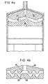
- Figures 4a and 4bare vertical cross sections of a fourth embodiment of a syringe according to the invention.
- Figure 5is a side view of a stand, or holder for engaging a syringe of the invention.
- Figures 6a and 6bare side views of a syringe according to the invention showing a first embodiment of plunger handles that can be detached.
- Figures 7a and 7bare side views of a syringe according to the invention showing a second embodiment of plunger handles that can be detached.
- Figures 8a and 8billustrate a further embodiment of a detachable plunger.
- Figure 9shows yet another embodiment of a detachable handle.
- Figure 10aillustrates a syringe having a ring that retains a piston
- figure 10billustrates a plunger handle that has been modified to accommodate the ring during assembly.
- Figures 11a and 11bshow vertical cross sections of a preferred seal for the plunger of a syringe.
- Figure 12illustrates a syringe according to the invention having a cap assembly that is attached during centrifugation.
- the inventionwill be described below in accordance with its operation as a syringe.
- Use with a syringeis advantageous because it allows the user to withdraw the physiological fluid into the syringe, place the syringe directly into a centrifuge for centrifugal processing, and then to express the several components from the syringe into separate containers. As such, this procedure requires only a single container without intermediate decanting steps. It will be understood, however, that many features of the invention do not require operation with a syringe or a single container and that the disk assembly to be described below may be used in combination with other containers as well.
- a floating element that automatically assumes a position just below the buffy coatis disclosed in WO 01/83068 .
- the disk disclosed thereis useful to separate the components of physiological fluids by centrifugation and finds its primary utility in structures that separate the components after centrifugation by decanting.
- the disk shown thereis useful, however, to separate components when used with a structure such as a syringe, and several examples of such use are described in United States Provisional Patent Application 60/471,352 .
- FIG. 1shows a preferred embodiment of a disk assembly in combination with a known syringe, which includes a cylindrical barrel portion 2, a conical end portion 4, and a tip portion 6.
- the syringealso includes a piston or plunger 8, which fits tightly in the cylindrical barrel and moves longitudinally to draw fluids into the barrel or express fluids from the barrel.
- a handle 10is attached to the plunger and is typically configured so that an operator can easily grasp it to move the plunger within the barrel. This structure is commonly found on syringes that can be obtained from many sources.
- a disk assemblycomprises an upper element 120 and a lower element 122 that is slidingly mounted on a pin 124 for relative movement with respect to element 120.
- a third element 126primarily provides lateral stability to the disk assembly and is mounted on the pin 124 in a fixed position.
- the three elementsfloat in the fluid and assume a predetermined position s will be described below. It will be appreciated that since element 122 is movable along the pin that some lateral stability can be lost when the distance between the upper element 120 and the movable element 122 is small and that the presence of the washer element 126 maintains stability. Other means for providing such stability such as longitudinally extending skirts may be used as well.
- the presence of the washer 126determines the maximum distance by which the element 122 can be displaced downward from the upper element. That maximum distance may be determined by other means, such as by a stop on the pin 124.
- the disk assemblycomprising elements 120, 122, and 126 is made of materials selected and configured such that the washer 126 assumes a position near the top of the layer of red blood cells.
- the assemblyis designed so that the "buffy coat,” lies just on the upper surface of the movable element 122, possibly with a few red blood cells also.
- This arrangementworks particularly well when the objective is to separate platelets, stem cells, white cells, and other cells from the red blood cells and plasma.
- the primary use of the preferred embodiments of the inventionis to separate, red blood cells, plasma, and the mix of cells typically found in the buffy coat from whole blood, bone marrow, bone marrow aspirate, or umbilical cord blood, and the embodiments of this invention will be described below in that context. It should be noted, however, that the methods and devices of the invention could be used to separate other fluids into components having different densities.
- the operatorfirst draws blood into the syringe by pulling the piston away from the conical end.
- the tip of the syringemay be connected to any one of several types of sources, and in the preferred embodiment, the syringe is attached to a needle so that blood is drawn into the syringe directly from a patient.
- the bloodmay be drawn from other places, such as a bag of blood obtained from the patient.
- the syringe having blood thereinis then placed in a centrifuge and subjected to centrifugation to cause the components of differing densities to separate into layers along the barrel. While the preferred structure by which the syringe is placed in the centrifuge will be described in detail below, it will be appreciated that a variety of structures may be used to attach the syringe to the rotor of a centrifuge.
- the disk assemblyeventually assumes a position between red blood cells and platelet poor plasma, where the buffy coat 14 lies on the upper surface 123 of the element 122.
- platelet poor plasma 12will be the upper layer (up being the orientation with the tip of the syringe pointing upward)
- red blood cells 13will be the bottom layer
- the buffy coat 14will be the intermediate layer. It will be understood that the layers as illustrated in figure 1 are not exact, particularly because the boundary between red blood cells and the buffy coat is diffuse.
- the distance between the upper element 120 and the movable element 122determines volume of plasma 12 captured between these elements.
- plasmawill surround the upper element 120, and red blood cells will surround the washer 126 and extend onto a small part of the upper surface of the movable element 122.
- the userpushes on the handle 10 to expresses the components in serial fashion.
- the buffy coatis quite thin, and a common problem faced when expressing the components is that turbulence occurring during expression, which causes the buffy coat to mix with the plasma and red blood cell layers. Thus significantly reduces the ability to express the buffy coat as a separate component or layer.
- the internal structure of the syringeis designed to provide a pathway for the fluids being expressed that avoids mixing the components. Because the buffy coat lies on the upper surface of the disk in the preferred embodiments, the configuration of the disk is preferably designed to cooperate with the internal surfaces of the syringe to provide the desired pathway.
- the top surface 121 of the upper element 120is preferably conical to conform to the shape of the conical end 4 of a syringe, whereby it will engage the end of the syringe during expression of the fluids. Other shapes are, of course possible.
- the upper element 120includes a flexible seal 128, which is preferably a thin annulus made of plastic that is flexible enough to allow cells to pass it during centrifugation but to resist that in normal handling of the syringe.
- the upper elementis made of two parts, and the seal rides freely in groove 130 formed between the two parts.
- the movable element 122is also made of two parts and includes a seal 132 that rides in groove 134.
- the flexible seals 128 and 132reduce mixing of the components during expression and handling, when the syringe may be placed in different orientations, e.g., when the user lays it horizontally on a table.
- the sealsprevent flow of the red blood cells from below the seal 132 into the predefined area between the upper and movable elements, which would reduce the effectiveness of the separation of the components.
- the provision of the sealsalso increases the allowable manufacturing tolerances and greatly reduces the possibility that deformations in the syringe barrel during operation of the syringe will adversely affect the operation of the device.
- Element 122includes several features that allow it to assist in positioning the disk assembly itself such that a small layer of red blood cells 13 lies just above the upper surface 123 of the element 122 and below the buffy coat 14. This ensures that the entire buffy coat is obtained and facilitates the expression of the buffy coat because the red blood cells tend to prevent attraction between the buffy coat and the upper surface of the movable element. Also, because the boundary between the buffy coat and the red blood cells is diffuse, it is not generally possible to obtain the entire buffy coat without including a small amount of the red blood cells.
- the movable element 122preferably includes a vertical density gradient provided by an upper part 136 having a density of about 1.04 and a lower part 138 having a density of approximately 1.08.
- the two parts of the movable partboth tend to sink in the plasma, the upper part, however, floats in the red blood cells, and the lower part sinks in red blood cells.
- the conical shape of the element 136causes the gradient of the buoyant forces to be non-linear at the boundary between the plasma and red blood cells. This has been found to increase the ability of the floating element to position itself such that the buffy coat lies either on the conical surface 123 or just above it.
- fluidsare drawn into the syringe, and some air is also drawn in. After centrifugation, the air will form a bubble at the top of the syringe. If the syringe is then inverted to express the platelet poor plasma between the element 120 and the end of the syringe, the bubble will move to a position between element 120 and the plasma. At that point, the user may express the platelet poor plasma into a cup. The user will know that the platelet poor plasma has been expressed when the air bubble 15 reaches the tip of the syringe. At that point the user can express the air until the upper end of the element 120 contacts the conical end of the syringe.
- the syringeis usually cylindrical, it may have other shapes. For example and oval cross section may be useful to prevent rotation of the parts.
- Figure 2illustrates an embodiment where the disk assembly comprises upper part 68 and lower part 70.
- the upper and lower disksform a cavity 72 between them, and the densities of the upper and lower parts are chosen such that the buffy coat 14 lies in the space 72.
- the upper and lower partsmay be attached together by circumferentially spaced strips 74 that allow fluids passing between the periphery of the lower part 70 and the wall 2 of the barrel portion to flow into the cavity 72.
- the embodiment of figure 2is advantageous because it captures the buffy coat in the relatively small space 72 between the upper and lower parts 68 and 70.
- This spaceis preferably made to be sufficiently small that the buffy coat will not mix with the plasma even if the syringe is not maintained in a strictly upright orientation or if the syringe is otherwise tilted or moved about in a fashion that would cause mixing in the embodiments described earlier. It will be appreciated that it is generally necessary to maintain the syringe upright so that the components that are to be dispensed separately are not mixed with each other.
- the embodiment of figure 2is aimed at reducing the requirement for handling the syringe with extreme care not to mix the components.
- the buffy coatis expressed in the embodiment of figure 2 much the same as in the other embodiments.
- the plasmais expressed first until the skirt portion 44 engages the syringe, and the red blood cells then flow into the cavity 72 as shown at 76 and flush the buffy coat upward through opening 20 and through the tip 6.
- the upper part 68 of the disk shown in figure 2includes a skirt 44 that engages in the annular portion 48.
- the upper end of the syringeis flat, and the upper surface of the upper element 68 is also generally flat to reduce the volume between these two when the disk is in the uppermost position. It will be understood, however, that the upper surface of the disk 68 could be conical if the upper end of the syringe were conical.
- the upper surface of the diskcan contact and seal against the inner surface of the syringe.
- Figures 3a and 3billustrate another embodiment that has a two-part disk.
- the upper part 78 of the diskmay move with respect to the lower part 80.
- the lower part 80is provided with a skirt 44 and openings 82 to allow fluid to flow radially inward during expression of the buffy coat.
- the upper part 78is made of material less dense than plasma (e.g., LDPE) and is supported on the skirt by elements 84 that allow vertical movement of the upper element along the skirt. Of course other arrangements may be provided to provide this motion.
- LDPElow density polyethylene
- Both parts of the diskwill move upward during expression of the plasma, and the upper part will eventually engage the end of the syringe.
- the lower partwill move upward further as illustrated in figure 3b while the upper part is constrained against further movement. This will reduce the size of the space 72 and express the plasma and then the buffy coat from the syringe.
- Figures 4a and 4bshow yet another modification wherein an upper part 86 and a lower part 88 of the disk are configured to provide an annular trough for receiving the buffy coat. These two parts may be configured to move with respect to each other as in the embodiment of figure 3 .
- the upper part 86has a protruding annular portion 90
- the lower parthas an annular trough 92 that matches the portion 90.
- the trough 92receives the buffy coat, and when the fluids flow radially inward during expression the buffy coat is expressed as illustrated by the arrows.
- Figure 4bshows a similar concept where the surfaces 90 and 92 are serpentine.
- Figure 5shows an optional stand designed to hold a syringe and facilitate expression of the components.
- the standincludes a base 94 that includes a vertical rod 96 on which the syringe is placed so that the rod contacts the piston or plunger.
- the syringeis engaged by a movable carriage 98, which is fitted to the base by coacting elements to ride vertically on the base.
- the user's fingersmay grasp a handle 100, and the user's thumb can engage the top of the carriage 98.
- the usercan push the syringe downward against the rod to move the piston upward and express the components.
- a tube 102is connected to the tip of the syringe to direct the components to the desired container, such as small cups for receiving, for example, platelet poor plasma and the buffy coat.
- An optical elementmay be mounted on a projection 104 to provide audible or other signals regarding the boundaries of the components to be expressed.
- Figures 6 and 7illustrate alternate designs for the syringe whereby the handles are easily removed.
- the handlesshould be removed before the syringe is placed in a centrifuge. After centrifugation, the syringe may be placed in a stand such as that shown in figure 5 , the handle reinstalled, or the like.
- the plunger 8may include a tab 106 that engages a hook 108 or similar element on the end of the handle 10. The hook may be disengaged when the piston is fully withdrawn as shown in figure 6b .
- Figures 7a and 7bshow a similar arrangement except that the lower surface 110 of the hook is angled whereby it automatically disengages.
- FIGS 8a and 8bshow additional details of the structure of the hook 108.
- the hook shown in these figuresis reinforced by a flange 118, which stiffens it against bending.
- Figure 9illustrates a hook that has a reinforcing rib 119 that is received in a slot 121 in the plunger
- the handlemay be configured such that its shape can be changed such that the syringe may be placed in the centrifuge.
- the handlemay be configured so that it can be bent to a position that allows the syringe to be placed in the centrifuge.
- Figure 10aillustrates structure that facilitates construction of a syringe according to the invention.
- the disk assembly and the plunger 8must be inserted into the barrel 2.
- a stopmust be provided to prevent withdrawal of the plunger when the syringe has been filled with blood.
- a ring 112is provided that is attached to the end of the barrel.
- the ring 112is spin-welded to the barrel during manufacture.
- Figure 10bshows a handle 10 with a depression 114 that provides space for the spin-welding machinery to be attached to the ring 112 during manufacture.
- Figures 11a and 11bare vertical cross-sections of a preferred form of seal for the plunger seal 140.
- the sealis made of resilient material and engages the upper wall of the plunger.
- a vertical sectionextends over the edge of the upper wall and downwardly toward a lower wall.
- edge portions 142engage the interior surface of the syringe barrel 2.
- the bottom of the sealis displaced from the lower wall by a gap 144. This provides an adequate seal to prevent leakage when the contents of the syringe are subjected to pressures near atmospheric.
- the seal 140is designed to deform as shown in figure 11b by application of increased pressure by the fluids whereby the lower edge is made less concave, which presses the edge 142 outward against the wall 2 of the syringe with increased force increasing the sealing capability.
- the increase in the diameter of the seal due to its flattening outis accommodated by a reduction in the size of the gap 144.
- Figure 12illustrates a further improvement.
- the centrifugal forces on the fluids, the plunger, and the syringe barrelare strong enough that the plunger will naturally move outward slightly. That will cause some air to enter the barrel cavity.
- the elementsmay recover their initial positions, which causes expression of the air.
- a cap 116 of hydrophobic materialis placed over the end of the tip 6 after blood has been drawn into the syringe. This provides a barrier to entry of bacteria after the blood has been drawn into the syringe and prevents discharge of blood from the syringe during handling and centrifugation.
Landscapes
- Health & Medical Sciences (AREA)
- Chemical & Material Sciences (AREA)
- Chemical Kinetics & Catalysis (AREA)
- General Health & Medical Sciences (AREA)
- Hematology (AREA)
- Clinical Laboratory Science (AREA)
- Analytical Chemistry (AREA)
- External Artificial Organs (AREA)
- Medicines Containing Material From Animals Or Micro-Organisms (AREA)
- Centrifugal Separators (AREA)
- Sampling And Sample Adjustment (AREA)
- Cyclones (AREA)
- Extraction Or Liquid Replacement (AREA)
- Separation Using Semi-Permeable Membranes (AREA)
Abstract
Description
- This invention relates to a unique element that floats in a physiological fluid undergoing centrifugation and assumes a location encompassing the boundary region between two components of different densities, and facilitates the isolation of a desired component found in the boundary region. Specifically, the floating element greatly facilitates the isolation and separation of the buffy coat from plasma and red blood cells.
- Another aspect of the invention is the provision of a device for use both as a syringe for withdrawing physiological fluids and as a chamber for separating the components of the fluids. In its preferred embodiments, the invention is a syringe configured to withdraw fluids from a patient in known fashion and subsequently to be placed directly in the rotor of a centrifuge for separating components of different densities. The syringe is thereafter operated to express the components in serial fashion, for example, into separate cups.
- Processing physiological fluids by centrifugation for separating the fluids into components of different densities is known. Physiological fluids include, for example, peripheral blood, umbilical cord blood, and bone marrow aspirate and ordinarily include cellular components. The physiological fluids subjected to the processes described herein may be obtained directly from a patient being treated, in which case the fluids are autologous, obtained from a donor, or obtained from a plurality of donors, in which case the fluids are homologous. While the objects of the invention are primarily concerned with the treatment of human fluids, it will be appreciated that the methods and apparatus described herein are equally applicable to fluids from other species.
- A primary objective of the invention is to isolate and obtain a layer of cells that forms during centrifugation and includes, among other components, platelets, white cells, stem cells, and nucleated cells. This layer is known as the buffy coat, and its density is between that of the red blood cells (1.08-1.09) and that of plasma (1.017-1.026). Plasma with most of the cellular components removed is known as platelet poor plasma (PPP), while plasma with its cellular components is known as platelet rich plasma(PRP). Platelet rich plasma has been found to produce several beneficial effects, such as a more rapid healing of wounds. Thus, another objective of the invention is to provide plasma with an increased level of platelets. This is known as a platelet concentrate (PC) or more broadly as a cell concentrate (CC). A typical concentration is four or more times the native concentration, and a typical ratio of input volume to cell concentrate volume is 6:1. Platelet or cell concentrates obtained by the invention comprises the buffy coat and plasma and may include a small amount of red blood cells.
- One of the problems addressed by the present invention is that the specific proportion of the various components and, even, the density of the cells themselves are unique to the particular donor, which precludes an exacta priori determination of the location of any given component in the fluid after centrifugation. For example, the proportion of red blood cells in blood, the hematocrit, varies with each patient, and the average density of the red blood cell component varies with its proportion of neocytes, young red blood cells, whose density is less than 1.08.
- Furthermore, the particular technique used to collect the fluids impacts the density of the cells. An anticoagulant is typically added to blood as it is collected, and the amount of anticoagulant and the particular anticoagulant used affects the density, particularly, of red blood cells. This is termed the lesion of collection and results from the effect of the anticoagulant on the osmolarity of the cells. For example, when the anticoagulant is acid citrate dextrose, ACD, red cells become hypo-osmolar and the cells draw water through the dell membrane, which decreases the density of the cells. Other anticoagulants, such as tri-sodium citrate at a concentration of 3.8%, are somewhat hyper-osmolar, which results in shrinkage of the red blood cells and an increase in their density. CPD is iso-osmolar and has much less effect on the density of the cells. CPD and tri-sodium phosphate are preferred and have produced superior results in separations of the kind contemplated herein.
- A further factor is that the layers of components form along the radius of centrifugation and are thus cylindrical, which complicates the design of structural elements for separating or collecting the layers.
- A system for separating blood into components for producing a platelet concentrate is described in United States Patent No.
6,398,972 . The system described in that patent uses a disposable processing unit having two chambers. Blood is drawn into a known syringe and expressed from the syringe into a first chamber of the processing unit. The processing unit is then placed in a centrifuge designed to automatically transfer supernatant fluids from one chamber to another. After a first centrifugation, platelet rich plasma is transferred into the second chamber, and the centrifuge is operated a second time to separate platelets from platelet poor plasma. While this system has many advantages, it has the disadvantage that the blood must be transferred from the syringe to the processing unit, and the centrifuge and the orientation of the processing unit must be controlled to decant the platelet rich plasma to the second chamber. - The first chamber of the system described in the '972 patent includes a disk that is positioned generally at the intersection of the red blood cells and the plasma to prevent decanting of red blood cells into the second chamber.
- United States Patent
5,456,885 shows a system wherein a collection tube is placed directly in a centrifuge to allow separation of the components. A floating element assumes a position between the plasma and the red blood cells and also acts as a check valve when the lighter phase is expressed from the tube. Systems of this type are, however, not generally capable of separating the buffy coat from the platelet-poor plasma and the red blood cells. US 4,152,270 discloses a system for separating fluid phases, such as blood. The system has a phase partitioning device having a specific gravity intermediate those of the light and heavy phases of the blood so that it automatically moves during centrifugation to substantially the interface of the phases to sealingly partition them from each other. The system does not comprise any specific means for expressing both separated fluids.US 4,088,582 discloses a system for separating different phases of a fluid, such as blood. As for '270, the system does not comprise any specific means for expressing both separated fluids.EP1106252 discloses another system having a means which seems to be a partitioning device. However, it is designed for mixing testing reagents with a fluid such as blood. In particular, when centrifugation occurs, an elastic barrel belonging to said partitioning device deforms so that a circumferential passageway around the elastic barrel appears for mixing the reagents. Accordingly, it cannot be used for separating blood phases.- The known centrifuges operate according to a particular protocol when it is desired to obtain a component of intermediate density. For example, when the object is to obtain platelets, it is known to subject blood to a first centrifugation to separate heavier components, such as red blood cells, from plasma, transferring the plasma to a second container or chamber by decanting and then subjecting the plasma to a second centrifugation to separate the plasma from the platelets. The platelets are then separated from the plasma in a second decanting step.
- Known techniques for obtaining the desired component of intermediate density are complicated because they require multiple centrifugations and multiple decant or centrifugal transfer steps. Also, the separation of a single component is often complicated because the physical, fluid properties of the desired component may tend to cause it to mix with the other components.
- The buffy coat layer is easily disrupted, and when one attempts to express platelet poor plasma through the tip of a syringe, the buffy coat often mixes with the plasma or with the red blood cells. This effectively prevents the expressing of the buffy coat layer either by itself or with only a negligible amount of the other components.
- As well, known tubes or syringes designed to be supplied directly to a centrifuge are difficult to use effectively.
- In accordance with the invention, an improved device is provided for separating components having differing densities in a centrifuge and isolating and dispensing a desired one of these components. The device may take the form of a syringe in the sense that it can be provided with a plunger and operated to draw a fluid, such as blood, bone marrow aspirate, or other physiological fluids, into a chamber through one end and to express the components through that end after separation. The device may, howcvcr, be a container of other configurations capable of being placed in a centrifuge and not necessarily designed to operate as a syringe.
- A particular objective of the invention is to obtain a cell concentrate from whole blood (including umbilical cord blood), bone marrow aspirate, or other physiological fluid in an efficient fashion through centrifugation and the expressing of the several components. The cell concentrate preferably includes the buffy coat, some red cells, and plasma in desired ratio. The buffy coat is a thin layer that forms during centrifugation and includes mostly all of the cells other than the red blood cells. The buffy coat is known to include platelets, white cells, nucleated cells, and stem sells cells and may include other components as well. Because the buffy coat is a somewhat diffuse layer that is easily disrupted and mixed with the other components, which reduces the effectiveness of the procedure, an object of the invention is to provide a container that can be operated to dispense the cell concentrate without significant mixing of the desired cells with the plasma or the red blood cells. This is accomplished in the preferred embodiments primarily by providing a flow path for the cell concentrate that reduces mixing between the components. In the preferred embodiments, a disk assembly floats in a region containing an interface between plasma and the buffy coat and a diffuse interface between the buffy coat and the red cells, and assists in separating those components. As well, the disk assembly is shaped so that it forms a flow path for the components and reduces turbulence during separation of the components to prevent mixing the components during their expression.
- More precisely, an objective of the invention is to propose a system according to claim 1.
- In its preferred embodiment, a disk assembly that is allowed to float in the fluid presents a vertical gradient in the buoyant forces that cause it to assume a position in the region having the desired component, e.g., the buffy coat. This gradient is provided either by the shape of the assembly, by the use of materials of different densities, or by a combination of both. In the preferred embodiment, the disk assembly provides a conical upper surface, and an upper portion of the assembly is made of a material that is less dense than red blood cells but more dense that plasma. A lower portion of the assembly is made of a material that is denser than the red blood cells. Because of the conical shape, the buoyant force provided by the upper element at the boundary between the plasma and the red blood cells and in the region of the buffy coat is a non-linear function of the distance by which the upper element extends into the plasma. The density gradient of the fluids in the boundary region is large, and the use of a floating element with a density gradient also has been found to be beneficial.
- The disk assembly according to the invention is designed to encompass both a desired component and a predetermined volume of fluid surrounding the desired component. In the preferred embodiment, the disk assembly comprises two floating parts that are movable relative to each other whereby the entire assembly is caused to assume a desired position after centrifugation, and one part moves toward the other during expression of the fluids to express a desired component or components, e.g., the buffy coat and a predetermined volume of plasma. This structure allows the user to obtain a cell concentrate comprising the buffy coat mixed with plasma at a desired increased concentration.
- The invention also relates to perfecting mechanical features, such as a handle for a plunger that accommodates placing the syringe in a centrifuge, and a stand for holding the syringe after centrifugation for facilitating expression of the components. The handle may be detachable or flexible whereby the distance by which it extends from the end of the barrel when the syringe is full is greatly reduced.
- It is an object of this invention to provide a device for use in separating the various components of a fluid by placing the fluid in the device, subjecting the device and fluid to centrifugation, and then expressing the components.
- It is a further object of this invention to provide a syringe for withdrawing fluids from a container or from the patient, for being placed directly into a centrifuge, and for expressing the separated components in serial fashion with minimal mixing.
Figure 1 is a vertical cross section of a first embodiment of a syringe according to the invention.Figure 2 is a vertical cross section of a second embodiment of a syringe according to the invention.Figures 3a and 3b are vertical cross sections of a third embodiment of a syringe according to the invention.Figures 4a and 4b are vertical cross sections of a fourth embodiment of a syringe according to the invention.Figure 5 is a side view of a stand, or holder for engaging a syringe of the invention.Figures 6a and 6b are side views of a syringe according to the invention showing a first embodiment of plunger handles that can be detached.Figures 7a and 7b are side views of a syringe according to the invention showing a second embodiment of plunger handles that can be detached.Figures 8a and 8b illustrate a further embodiment of a detachable plunger.Figure 9 shows yet another embodiment of a detachable handle.Figure 10a illustrates a syringe having a ring that retains a piston, andfigure 10b illustrates a plunger handle that has been modified to accommodate the ring during assembly.Figures 11a and 11b show vertical cross sections of a preferred seal for the plunger of a syringe.Figure 12 illustrates a syringe according to the invention having a cap assembly that is attached during centrifugation.- The invention will be described below in accordance with its operation as a syringe. Use with a syringe is advantageous because it allows the user to withdraw the physiological fluid into the syringe, place the syringe directly into a centrifuge for centrifugal processing, and then to express the several components from the syringe into separate containers. As such, this procedure requires only a single container without intermediate decanting steps. It will be understood, however, that many features of the invention do not require operation with a syringe or a single container and that the disk assembly to be described below may be used in combination with other containers as well.
- A floating element that automatically assumes a position just below the buffy coat is disclosed in
WO 01/83068 60/471,352 - A primary objective of the present invention is to facilitate the production of a cell concentrate having a defined volume of plasma and at least a major portion of the buffy coat. With reference to the drawings,
figure 1 shows a preferred embodiment of a disk assembly in combination with a known syringe, which includes acylindrical barrel portion 2, a conical end portion 4, and a tip portion 6. The syringe also includes a piston orplunger 8, which fits tightly in the cylindrical barrel and moves longitudinally to draw fluids into the barrel or express fluids from the barrel. Ahandle 10 is attached to the plunger and is typically configured so that an operator can easily grasp it to move the plunger within the barrel. This structure is commonly found on syringes that can be obtained from many sources. - In accordance with the embodiment shown in
figure 1 , a disk assembly comprises an upper element 120 and alower element 122 that is slidingly mounted on apin 124 for relative movement with respect to element 120. Athird element 126 primarily provides lateral stability to the disk assembly and is mounted on thepin 124 in a fixed position. Thus, in the embodiment offigure 1 , the three elements float in the fluid and assume a predetermined position s will be described below. It will be appreciated that sinceelement 122 is movable along the pin that some lateral stability can be lost when the distance between the upper element 120 and themovable element 122 is small and that the presence of thewasher element 126 maintains stability. Other means for providing such stability such as longitudinally extending skirts may be used as well. - It will also be appreciated that the presence of the
washer 126 determines the maximum distance by which theelement 122 can be displaced downward from the upper element. That maximum distance may be determined by other means, such as by a stop on thepin 124. - In the preferred embodiment, the disk
assembly comprising elements washer 126 assumes a position near the top of the layer of red blood cells. Preferably, the assembly is designed so that the "buffy coat," lies just on the upper surface of themovable element 122, possibly with a few red blood cells also. This arrangement works particularly well when the objective is to separate platelets, stem cells, white cells, and other cells from the red blood cells and plasma. The primary use of the preferred embodiments of the invention is to separate, red blood cells, plasma, and the mix of cells typically found in the buffy coat from whole blood, bone marrow, bone marrow aspirate, or umbilical cord blood, and the embodiments of this invention will be described below in that context. It should be noted, however, that the methods and devices of the invention could be used to separate other fluids into components having different densities. - The operator first draws blood into the syringe by pulling the piston away from the conical end. The tip of the syringe may be connected to any one of several types of sources, and in the preferred embodiment, the syringe is attached to a needle so that blood is drawn into the syringe directly from a patient. The blood may be drawn from other places, such as a bag of blood obtained from the patient. The syringe having blood therein is then placed in a centrifuge and subjected to centrifugation to cause the components of differing densities to separate into layers along the barrel. While the preferred structure by which the syringe is placed in the centrifuge will be described in detail below, it will be appreciated that a variety of structures may be used to attach the syringe to the rotor of a centrifuge.
- In accordance with a preferred embodiment, during centrifugation the disk assembly eventually assumes a position between red blood cells and platelet poor plasma, where the
buffy coat 14 lies on theupper surface 123 of theelement 122. When the centrifugation is stopped, plateletpoor plasma 12 will be the upper layer (up being the orientation with the tip of the syringe pointing upward),red blood cells 13 will be the bottom layer, and thebuffy coat 14 will be the intermediate layer. It will be understood that the layers as illustrated infigure 1 are not exact, particularly because the boundary between red blood cells and the buffy coat is diffuse. - It will also be appreciated that the distance between the upper element 120 and the
movable element 122 determines volume ofplasma 12 captured between these elements. Thus, after centrifugation, plasma will surround the upper element 120, and red blood cells will surround thewasher 126 and extend onto a small part of the upper surface of themovable element 122. After centrifugation, the user pushes on thehandle 10 to expresses the components in serial fashion. - The buffy coat is quite thin, and a common problem faced when expressing the components is that turbulence occurring during expression, which causes the buffy coat to mix with the plasma and red blood cell layers. Thus significantly reduces the ability to express the buffy coat as a separate component or layer. In accordance with a primary aspect of the invention, the internal structure of the syringe is designed to provide a pathway for the fluids being expressed that avoids mixing the components. Because the buffy coat lies on the upper surface of the disk in the preferred embodiments, the configuration of the disk is preferably designed to cooperate with the internal surfaces of the syringe to provide the desired pathway.
- The
top surface 121 of the upper element 120 is preferably conical to conform to the shape of the conical end 4 of a syringe, whereby it will engage the end of the syringe during expression of the fluids. Other shapes are, of course possible. The upper element 120 includes aflexible seal 128, which is preferably a thin annulus made of plastic that is flexible enough to allow cells to pass it during centrifugation but to resist that in normal handling of the syringe. In the preferred embodiment shown infigure 1 , the upper element is made of two parts, and the seal rides freely ingroove 130 formed between the two parts. Themovable element 122 is also made of two parts and includes aseal 132 that rides ingroove 134. - The
flexible seals seal 132 into the predefined area between the upper and movable elements, which would reduce the effectiveness of the separation of the components. The provision of the seals also increases the allowable manufacturing tolerances and greatly reduces the possibility that deformations in the syringe barrel during operation of the syringe will adversely affect the operation of the device. Element 122 includes several features that allow it to assist in positioning the disk assembly itself such that a small layer ofred blood cells 13 lies just above theupper surface 123 of theelement 122 and below thebuffy coat 14. This ensures that the entire buffy coat is obtained and facilitates the expression of the buffy coat because the red blood cells tend to prevent attraction between the buffy coat and the upper surface of the movable element. Also, because the boundary between the buffy coat and the red blood cells is diffuse, it is not generally possible to obtain the entire buffy coat without including a small amount of the red blood cells.- The
movable element 122 preferably includes a vertical density gradient provided by anupper part 136 having a density of about 1.04 and alower part 138 having a density of approximately 1.08. By this construction, the two parts of the movable part both tend to sink in the plasma, the upper part, however, floats in the red blood cells, and the lower part sinks in red blood cells. In addition to the density gradient presented by the use of the two materials, it will be appreciated that the conical shape of theelement 136 causes the gradient of the buoyant forces to be non-linear at the boundary between the plasma and red blood cells. This has been found to increase the ability of the floating element to position itself such that the buffy coat lies either on theconical surface 123 or just above it. - In operation, fluids are drawn into the syringe, and some air is also drawn in. After centrifugation, the air will form a bubble at the top of the syringe. If the syringe is then inverted to express the platelet poor plasma between the element 120 and the end of the syringe, the bubble will move to a position between element 120 and the plasma. At that point, the user may express the platelet poor plasma into a cup. The user will know that the platelet poor plasma has been expressed when the
air bubble 15 reaches the tip of the syringe. At that point the user can express the air until the upper end of the element 120 contacts the conical end of the syringe. At that point, further movement of the plunger will cause the red blood cells below theelement 122 to moveelement 122 upward to express the plasma and buffy coat that lie between theelements 120 and 122. These materials will flow through achannel 146 between thepin 124 and the lower part of element 120 and then through ahole 148 in the upper part. As the plunger is advanced, theelement 122 will move upward until all of the material betweenelements 120 and 122, namely the plasma and the buffy coat, and a few red blood cells in the preferred embodiment, has been expressed. At this point, the force required to advance the plunger will increase significantly because the red blood cells will have to move past theseals - While the syringe is usually cylindrical, it may have other shapes. For example and oval cross section may be useful to prevent rotation of the parts.
Figure 2 illustrates an embodiment where the disk assembly comprisesupper part 68 andlower part 70. The upper and lower disks form acavity 72 between them, and the densities of the upper and lower parts are chosen such that thebuffy coat 14 lies in thespace 72. The upper and lower parts may be attached together by circumferentially spacedstrips 74 that allow fluids passing between the periphery of thelower part 70 and thewall 2 of the barrel portion to flow into thecavity 72.- The embodiment of
figure 2 is advantageous because it captures the buffy coat in the relativelysmall space 72 between the upper andlower parts figure 2 is aimed at reducing the requirement for handling the syringe with extreme care not to mix the components. - The buffy coat is expressed in the embodiment of
figure 2 much the same as in the other embodiments. As the piston or plunger of the syringe is advanced, the plasma is expressed first until theskirt portion 44 engages the syringe, and the red blood cells then flow into thecavity 72 as shown at 76 and flush the buffy coat upward through opening 20 and through the tip 6. It will be appreciated that theupper part 68 of the disk shown infigure 2 includes askirt 44 that engages in theannular portion 48. Also, the upper end of the syringe is flat, and the upper surface of theupper element 68 is also generally flat to reduce the volume between these two when the disk is in the uppermost position. It will be understood, however, that the upper surface of thedisk 68 could be conical if the upper end of the syringe were conical. - Also, the upper surface of the disk can contact and seal against the inner surface of the syringe.
Figures 3a and 3b illustrate another embodiment that has a two-part disk. In this embodiment, theupper part 78 of the disk may move with respect to thelower part 80. Thus, thelower part 80 is provided with askirt 44 andopenings 82 to allow fluid to flow radially inward during expression of the buffy coat. Theupper part 78 is made of material less dense than plasma (e.g., LDPE) and is supported on the skirt byelements 84 that allow vertical movement of the upper element along the skirt. Of course other arrangements may be provided to provide this motion. The result is that the buffy coat will be contained in thecavity 72 between the two elements. Because the upper element floats in the plasma, thespace 72 will initially be larger than required to contain only the buffy coat. Both parts of the disk will move upward during expression of the plasma, and the upper part will eventually engage the end of the syringe. As the plunger is moved further upward, the lower part will move upward further as illustrated infigure 3b while the upper part is constrained against further movement. This will reduce the size of thespace 72 and express the plasma and then the buffy coat from the syringe.Figures 4a and 4b show yet another modification wherein anupper part 86 and alower part 88 of the disk are configured to provide an annular trough for receiving the buffy coat. These two parts may be configured to move with respect to each other as in the embodiment offigure 3 . In the embodiment offigure 4a theupper part 86 has a protrudingannular portion 90, and the lower part has anannular trough 92 that matches theportion 90. Thetrough 92 receives the buffy coat, and when the fluids flow radially inward during expression the buffy coat is expressed as illustrated by the arrows.Figure 4b shows a similar concept where thesurfaces - The previous discussion has not assumed any particular mechanism for advancing the piston or plunger.
Figure 5 shows an optional stand designed to hold a syringe and facilitate expression of the components. The stand includes a base 94 that includes avertical rod 96 on which the syringe is placed so that the rod contacts the piston or plunger. The syringe is engaged by amovable carriage 98, which is fitted to the base by coacting elements to ride vertically on the base. The user's fingers may grasp ahandle 100, and the user's thumb can engage the top of thecarriage 98. Thus, the user can push the syringe downward against the rod to move the piston upward and express the components. Atube 102 is connected to the tip of the syringe to direct the components to the desired container, such as small cups for receiving, for example, platelet poor plasma and the buffy coat. An optical element may be mounted on aprojection 104 to provide audible or other signals regarding the boundaries of the components to be expressed. Figures 6 and7 illustrate alternate designs for the syringe whereby the handles are easily removed. For example, the handles should be removed before the syringe is placed in a centrifuge. After centrifugation, the syringe may be placed in a stand such as that shown infigure 5 , the handle reinstalled, or the like. As shown infigure 6a , theplunger 8 may include atab 106 that engages ahook 108 or similar element on the end of thehandle 10. The hook may be disengaged when the piston is fully withdrawn as shown infigure 6b .Figures 7a and 7b show a similar arrangement except that thelower surface 110 of the hook is angled whereby it automatically disengages. Thus, when the handle is not fully withdrawn, the side of the handle engages the barrel portion of the syringe and prevents disengagement. When the handle is fully withdrawn, the handle is then able to move transversely with respect to the barrel, and application of a longitudinal force to the handle, as is normal when withdrawing the piston, automatically applies a transverse force to the hook, causing it to disengage as shown infigure 6b .Figures 8a and 8b show additional details of the structure of thehook 108. The hook shown in these figures is reinforced by aflange 118, which stiffens it against bending.Figure 9 illustrates a hook that has a reinforcingrib 119 that is received in aslot 121 in the plunger- Alternatively, the handle may be configured such that its shape can be changed such that the syringe may be placed in the centrifuge. As one example, the handle may be configured so that it can be bent to a position that allows the syringe to be placed in the centrifuge.
Figure 10a illustrates structure that facilitates construction of a syringe according to the invention. To assemble the syringe, the disk assembly and theplunger 8 must be inserted into thebarrel 2. A stop must be provided to prevent withdrawal of the plunger when the syringe has been filled with blood. Thus, as shown infigure 10a , aring 112 is provided that is attached to the end of the barrel. Preferably, thering 112 is spin-welded to the barrel during manufacture.Figure 10b shows ahandle 10 with adepression 114 that provides space for the spin-welding machinery to be attached to thering 112 during manufacture.Figures 11a and 11b are vertical cross-sections of a preferred form of seal for theplunger seal 140. The seal is made of resilient material and engages the upper wall of the plunger. A vertical section extends over the edge of the upper wall and downwardly toward a lower wall. When the syringe is not undergoing centrifugation, the upper surface of the seal is generally concave upwardly, andedge portions 142 engage the interior surface of thesyringe barrel 2. Also, the bottom of the seal is displaced from the lower wall by agap 144. This provides an adequate seal to prevent leakage when the contents of the syringe are subjected to pressures near atmospheric. When the syringe is subjected to centrifugation, however, the pressure applied by the fluid on theseal 140 is greatly increased, and additional sealing capability is required. Thus, theseal 140 is designed to deform as shown infigure 11b by application of increased pressure by the fluids whereby the lower edge is made less concave, which presses theedge 142 outward against thewall 2 of the syringe with increased force increasing the sealing capability. The increase in the diameter of the seal due to its flattening out is accommodated by a reduction in the size of thegap 144.Figure 12 illustrates a further improvement. During centrifugation, the centrifugal forces on the fluids, the plunger, and the syringe barrel are strong enough that the plunger will naturally move outward slightly. That will cause some air to enter the barrel cavity. When the centrifugation terminates, the elements may recover their initial positions, which causes expression of the air. To allow this to occur without compromising sterility, a cap 116 of hydrophobic material is placed over the end of the tip 6 after blood has been drawn into the syringe. This provides a barrier to entry of bacteria after the blood has been drawn into the syringe and prevents discharge of blood from the syringe during handling and centrifugation.- Modifications within the scope of the appended claims will be apparent to those of skill in the art.
Claims (17)
- An assembly for use in centrifugal separation of a fluid into components, comprising a barrel (2) configured to contain said fluid and having an end portion (4, 44) through which fluid components can be expressed from said barrelcharacterized in that said assembly has the form of a syringe in the sense that it is provided with a plunger (8) and comprises by upper (120, 68, 78, 86) and lower (122, 70, 80, 88) spaced elements arranged in said barrel for movement in said fluid, said upper and lower elements being made of materials with respective densities such that said upper element (120, 68, 78, 86) floats above said lower element (122, 70, 80, 88) in said fluid after centrifugation, and wherein the configuration of the interior surface of said end portion (4, 44) of said barrel (2) conforms to the configuration of an upper surface of said upper element, whereby a first component of said fluid above said upper element (120, 68, 78, 86) may be expressedby the longitudinal movement of the plunger (8) in the barrel (2), and said upper element (120, 68, 80, 88) has a fluid channel (146) to pass fluid from beneath said upper element whereby a second component of said fluid between said upper and lower elements is subsequently expressed with said upper element in contact with said end portion (4, 44).
- An assembly according to claim 1 further including a pin (124) extending from said first element and carrying said second element.
- An assembly according to claim 2 further comprising a third element (126) below said second element for providing stability to said assembly.
- An assembly according to claim 1 wherein the lower element (122) is made of a material having a density gradient in the direction defined by said upper and lower elements.
- An assembly according to claim 1 wherein said one of said elements (120, 122) is conical.
- An assembly according to claim 1 further comprising a peripheral seal (128, 132) on at least one of said elements.
- An assembly according to claim 1 further comprising strips (74) circumferentially attached to the upper and lower element for allowing a fluid below said lower element to flow into a cavity (72) between said elements and express fluids in said cavity (72) through said fluid channel.
- An assembly according to claim 1 wherein said upper (78, 86) and lower (80, 88) elements are movable with respect to each other and configured to provide a cavity (72) between them for receiving a second component of said fluid and to express said second component of said fluid as said upper and lower elements move toward each other.
- An assembly according to claim 8 wherein a periphery of said upper element (78) is configured to slide on a periphery of said lower element (80) whereby said upper element (78) may move with respect to said lower element.
- An assembly according to claim 8 wherein a lower surface (90) of said upper element (86) and an upper surface (92) of said lower element (88) have mating troughs.
- A method of separating components of a fluid by centrifugation comprising the steps of providing a syringe having a barrel with an end portion, a plunger and upper and lower spaced floating elements in said barrel, said upper and lower elements having respective densities such that said upper element floats above said lower element in said fluid after centrifugation, and the configuration of an interior surface of said end portion conforms to the configuration of an upper surface of said upper element, drawing said fluid into said syringe, placing said syringe and fluid in a centrifuge and subjecting them to centrifugation, and expressing a first separated component above_said upper element from said syringe through said end portion, and subsequently expressing a second separated component between said upper and lower elements from said end portion.
- A method according to claim 11 wherein said step of expressing comprises expressing a first component until said upper surface of said upper element engages said interior surface.
- A method according to claim 11 wherein said upper and lower elements are connected to each other to define their maximum separation.
- A method according to claim 11 wherein said upper and lower elements are I movable with respect to each other.
- A method according to claim 14 wherein said step of expressing comprises I the step of causing said lower element to move toward said upper element.
- A method according to claim 11 wherein said upper and lower elements (68, 70) are attached together by circumferentially spaced strips (74).
- A method according to claim 16 wherein said step of expressing comprises I causing a fluid component below said lower element to flow into a cavity between said upper and lower elements (68, 70) to expel a fluid component previously in said cavity.
Priority Applications (3)
| Application Number | Priority Date | Filing Date | Title |
|---|---|---|---|
| SI200431787TSI1638691T1 (en) | 2003-05-19 | 2004-05-19 | Method and apparatus for separating fluid components |
| PL04752641TPL1638691T3 (en) | 2003-05-19 | 2004-05-19 | Method and apparatus for separating fluid components |
| CY20111101165TCY1112098T1 (en) | 2003-05-19 | 2011-11-28 | METHOD AND APPLIANCE FOR LIQUID INGREDIENTS DIVISION |
Applications Claiming Priority (2)
| Application Number | Priority Date | Filing Date | Title |
|---|---|---|---|
| US47135203P | 2003-05-19 | 2003-05-19 | |
| PCT/US2004/015654WO2004104553A2 (en) | 2003-05-19 | 2004-05-19 | Method and apparatus for separating fluid components |
Publications (3)
| Publication Number | Publication Date |
|---|---|
| EP1638691A2 EP1638691A2 (en) | 2006-03-29 |
| EP1638691A4 EP1638691A4 (en) | 2007-08-15 |
| EP1638691B1true EP1638691B1 (en) | 2011-08-31 |
Family
ID=33476835
Family Applications (1)
| Application Number | Title | Priority Date | Filing Date |
|---|---|---|---|
| EP04752641AExpired - LifetimeEP1638691B1 (en) | 2003-05-19 | 2004-05-19 | Method and apparatus for separating fluid components |
Country Status (14)
| Country | Link |
|---|---|
| US (5) | US7445125B2 (en) |
| EP (1) | EP1638691B1 (en) |
| JP (1) | JP4399453B2 (en) |
| CN (1) | CN1822903B (en) |
| AT (1) | ATE522273T1 (en) |
| AU (1) | AU2004242150B2 (en) |
| CA (1) | CA2526186C (en) |
| CY (1) | CY1112098T1 (en) |
| DK (1) | DK1638691T3 (en) |
| ES (1) | ES2372492T3 (en) |
| PL (1) | PL1638691T3 (en) |
| PT (1) | PT1638691E (en) |
| SI (1) | SI1638691T1 (en) |
| WO (1) | WO2004104553A2 (en) |
Families Citing this family (69)
| Publication number | Priority date | Publication date | Assignee | Title |
|---|---|---|---|---|
| US7947236B2 (en) | 1999-12-03 | 2011-05-24 | Becton, Dickinson And Company | Device for separating components of a fluid sample |
| US7992725B2 (en)* | 2002-05-03 | 2011-08-09 | Biomet Biologics, Llc | Buoy suspension fractionation system |
| US7832566B2 (en) | 2002-05-24 | 2010-11-16 | Biomet Biologics, Llc | Method and apparatus for separating and concentrating a component from a multi-component material including macroparticles |
| US20030205538A1 (en) | 2002-05-03 | 2003-11-06 | Randel Dorian | Methods and apparatus for isolating platelets from blood |
| US7374678B2 (en) | 2002-05-24 | 2008-05-20 | Biomet Biologics, Inc. | Apparatus and method for separating and concentrating fluids containing multiple components |
| US7845499B2 (en) | 2002-05-24 | 2010-12-07 | Biomet Biologics, Llc | Apparatus and method for separating and concentrating fluids containing multiple components |
| US20060278588A1 (en) | 2002-05-24 | 2006-12-14 | Woodell-May Jennifer E | Apparatus and method for separating and concentrating fluids containing multiple components |
| WO2003099412A1 (en) | 2002-05-24 | 2003-12-04 | Biomet Manufacturing Corp. | Apparatus and method for separating and concentrating fluids containing multiple components |
| PT1638691E (en)* | 2003-05-19 | 2011-12-16 | Harvest Technologies Corp | Method and apparatus for separating fluid components |
| US7708152B2 (en) | 2005-02-07 | 2010-05-04 | Hanuman Llc | Method and apparatus for preparing platelet rich plasma and concentrates thereof |
| EP2666493B1 (en) | 2005-02-07 | 2020-09-23 | Hanuman LLC | Platelet rich plasma concentrate apparatus |
| US7866485B2 (en) | 2005-02-07 | 2011-01-11 | Hanuman, Llc | Apparatus and method for preparing platelet rich plasma and concentrates thereof |
| US7694828B2 (en)* | 2005-04-27 | 2010-04-13 | Biomet Manufacturing Corp. | Method and apparatus for producing autologous clotting components |
| EP1852500A1 (en) | 2006-05-02 | 2007-11-07 | Stemwell LLC | Stem cells derived from bone marrow for tissue regeneration |
| US8567609B2 (en) | 2006-05-25 | 2013-10-29 | Biomet Biologics, Llc | Apparatus and method for separating and concentrating fluids containing multiple components |
| US7767087B2 (en) | 2007-01-05 | 2010-08-03 | Wilson Kelce S | Floating filter holder |
| JP5479319B2 (en)* | 2007-04-12 | 2014-04-23 | バイオメット・バイオロジックス・リミテッド・ライアビリティ・カンパニー | Buoy suspension fractionation system |
| US8328024B2 (en) | 2007-04-12 | 2012-12-11 | Hanuman, Llc | Buoy suspension fractionation system |
| DE102007034477A1 (en)* | 2007-07-20 | 2009-01-22 | Voco Gmbh | Syringe and method for metered dispensing of materials |
| JP5364102B2 (en) | 2007-12-07 | 2013-12-11 | ハーベスト・テクノロジーズ・コーポレイション | Floating disc for separating blood components |
| US8545440B2 (en) | 2007-12-21 | 2013-10-01 | Carticept Medical, Inc. | Injection system for delivering multiple fluids within the anatomy |
| US9044542B2 (en) | 2007-12-21 | 2015-06-02 | Carticept Medical, Inc. | Imaging-guided anesthesia injection systems and methods |
| WO2009086182A1 (en) | 2007-12-21 | 2009-07-09 | Carticept Medical, Inc. | Articular injection system |
| EP2259774B1 (en) | 2008-02-27 | 2012-12-12 | Biomet Biologics, LLC | Methods and compositions for delivering interleukin-1 receptor antagonist |
| US8337711B2 (en) | 2008-02-29 | 2012-12-25 | Biomet Biologics, Llc | System and process for separating a material |
| CN104068925B (en)* | 2008-03-26 | 2017-07-14 | 斯恩蒂斯有限公司 | For the universal anchor by physical attachment on bone tissue |
| US8012077B2 (en) | 2008-05-23 | 2011-09-06 | Biomet Biologics, Llc | Blood separating device |
| US8882838B2 (en)* | 2008-06-05 | 2014-11-11 | DePuy Synthes Products, LLC | Articulating disc implant |
| CN102046111A (en) | 2008-06-05 | 2011-05-04 | 斯恩蒂斯有限公司 | Articulating disc implant |
| BRPI0915953B1 (en)* | 2008-07-21 | 2021-04-13 | Becton, Dickinson And Company | MECHANICAL SEPARATOR, SEPARATION ASSEMBLY AND SEPARATING METHOD |
| CN102131972B (en) | 2008-11-14 | 2013-05-22 | 兴研株式会社 | Sheet-like assembly of fibers having small diameters, method for producing same, and apparatus for producing same |
| JP5759900B2 (en) | 2008-12-05 | 2015-08-05 | ジンテス ゲゼルシャフト ミット ベシュレンクテル ハフツング | Anchor-in-anchor system for use in bone fixation |
| US9060808B2 (en) | 2008-12-05 | 2015-06-23 | DePuy Synthes Products, Inc. | Anchor-in-anchor system for use in bone fixation |
| US8187475B2 (en) | 2009-03-06 | 2012-05-29 | Biomet Biologics, Llc | Method and apparatus for producing autologous thrombin |
| US8313954B2 (en)* | 2009-04-03 | 2012-11-20 | Biomet Biologics, Llc | All-in-one means of separating blood components |
| EP2416789B1 (en) | 2009-04-07 | 2017-06-21 | Velin-Pharma A/S | Method and device for treatment of conditions associated with inflammation or undesirable activation of the immune system |
| NZ711629A (en) | 2009-05-15 | 2016-05-27 | Becton Dickinson Co | Density phase separation device |
| DE102009022346B4 (en)* | 2009-05-15 | 2011-05-19 | Fraunhofer-Gesellschaft zur Förderung der angewandten Forschung e.V. | Automatic separation of fatty tissue |
| US9272083B2 (en) | 2009-05-29 | 2016-03-01 | Endocellutions, Inc. | Apparatus and methods for aspirating and separating components of different densities from a physiological fluid containing cells |
| WO2010151704A1 (en)* | 2009-06-24 | 2010-12-29 | Carticept Medical, Inc. | Injection system for delivering multiple fluids within the anatomy |
| US9011800B2 (en) | 2009-07-16 | 2015-04-21 | Biomet Biologics, Llc | Method and apparatus for separating biological materials |
| AU2010294197C9 (en) | 2009-09-10 | 2018-09-13 | Velin-Pharma A/S | Method for the preparation of micro-RNA and its therapeutic application |
| US8591391B2 (en) | 2010-04-12 | 2013-11-26 | Biomet Biologics, Llc | Method and apparatus for separating a material |
| KR101128163B1 (en)* | 2011-09-22 | 2012-03-23 | 황의재 | Disposable device for separating platelet rich plasma |
| KR101170028B1 (en)* | 2011-12-20 | 2012-08-01 | (주) 레보메드 | Blood separating apparatus |
| US9642956B2 (en) | 2012-08-27 | 2017-05-09 | Biomet Biologics, Llc | Apparatus and method for separating and concentrating fluids containing multiple components |
| US10603665B2 (en) | 2013-01-29 | 2020-03-31 | Endocellutions, Inc. | Cell concentration devices and methods that include an insert defining a lumen and a cannula assembly |
| US10143725B2 (en) | 2013-03-15 | 2018-12-04 | Biomet Biologics, Llc | Treatment of pain using protein solutions |
| US9895418B2 (en) | 2013-03-15 | 2018-02-20 | Biomet Biologics, Llc | Treatment of peripheral vascular disease using protein solutions |
| US9950035B2 (en) | 2013-03-15 | 2018-04-24 | Biomet Biologics, Llc | Methods and non-immunogenic compositions for treating inflammatory disorders |
| US20140271589A1 (en) | 2013-03-15 | 2014-09-18 | Biomet Biologics, Llc | Treatment of collagen defects using protein solutions |
| US10208095B2 (en) | 2013-03-15 | 2019-02-19 | Biomet Manufacturing, Llc | Methods for making cytokine compositions from tissues using non-centrifugal methods |
| US10258744B2 (en) | 2013-04-05 | 2019-04-16 | West Pharmaceutical Services, Inc. | Pharmaceutical syringe piston |
| WO2014168409A1 (en) | 2013-04-11 | 2014-10-16 | (주)굿모닝바이오 | Blood separation container for extracting self-platelet |
| JP6154904B2 (en)* | 2013-08-22 | 2017-06-28 | 株式会社ジェイ・エム・エス | Blood component separation device |
| US9988599B2 (en) | 2014-08-25 | 2018-06-05 | Reviticell Holdings, Inc. | Modular single-use kits and methods for preparation of biological material |
| US9694359B2 (en) | 2014-11-13 | 2017-07-04 | Becton, Dickinson And Company | Mechanical separator for a biological fluid |
| CN104458519B (en)* | 2014-12-08 | 2017-01-18 | 重庆南方数控设备有限责任公司 | Precise detecting method for obtaining erythrocyte sedimentation data |
| US9713810B2 (en) | 2015-03-30 | 2017-07-25 | Biomet Biologics, Llc | Cell washing plunger using centrifugal force |
| US9757721B2 (en) | 2015-05-11 | 2017-09-12 | Biomet Biologics, Llc | Cell washing plunger using centrifugal force |
| US10300481B2 (en) | 2015-06-17 | 2019-05-28 | Patrick Pennie | Centrifuge tube assembly for separating, concentrating and aspirating constituents of a fluid product |
| TR201718999A2 (en)* | 2017-11-28 | 2018-08-27 | Kemal Tunc Tiryaki | An injector end seal for stem cell housing |
| CA3101350A1 (en) | 2018-07-09 | 2020-01-16 | Hanuman Pelican, Inc. | Apparatus and methods for separating blood components |
| US11534533B2 (en) | 2018-07-09 | 2022-12-27 | Hanuman Pelican, Inc. | Apparatus and methods for processing blood |
| WO2020154305A1 (en) | 2019-01-21 | 2020-07-30 | Eclipse Medcorp, Llc | Methods, systems and apparatus for separating components of a biological sample |
| WO2020163105A1 (en) | 2019-02-06 | 2020-08-13 | Hanuman Pelican, Inc. | Apparatus and methods for concentrating platelet-rich plasma |
| US11272996B2 (en) | 2019-10-04 | 2022-03-15 | Reviticell Holdings, Inc. | Methods and devices for performing sequential procedures utilizing a standardized system |
| US12007382B2 (en) | 2019-10-31 | 2024-06-11 | Crown Laboratories, Inc. | Systems, methods and apparatus for separating components of a sample |
| WO2022159693A1 (en) | 2021-01-21 | 2022-07-28 | Patrick Pennie | Vented dual port centrifuge tube |
Family Cites Families (36)
| Publication number | Priority date | Publication date | Assignee | Title |
|---|---|---|---|---|
| US280820A (en)* | 1883-07-10 | Milk-can | ||
| US593333A (en)* | 1897-11-09 | Device for separating liquids of different | ||
| US3409165A (en)* | 1967-04-03 | 1968-11-05 | Olin Mathieson | Floating deck |
| US3508653A (en)* | 1967-11-17 | 1970-04-28 | Charles M Coleman | Method and apparatus for fluid handling and separation |
| US4001122A (en)* | 1973-08-22 | 1977-01-04 | Telan Corporation | Method and device for separating blood components |
| US3909419A (en)* | 1974-02-27 | 1975-09-30 | Becton Dickinson Co | Plasma separator with squeezed sealant |
| US3935113A (en)* | 1974-02-27 | 1976-01-27 | Becton, Dickinson And Company | Serum/plasma separator with centrifugal valve |
| US3941699A (en)* | 1974-02-27 | 1976-03-02 | Becton, Dickinson And Company | Plasma separator with centrifugal valve |
| US3951801A (en)* | 1974-02-27 | 1976-04-20 | Becton, Dickinson And Company | Serum/plasma separator-strut stop type |
| US3931010A (en)* | 1974-02-27 | 1976-01-06 | Becton, Dickinson And Company | Serum/plasma separators with centrifugal valves |
| US3929646A (en)* | 1974-07-22 | 1975-12-30 | Technicon Instr | Serum separator and fibrin filter |
| US3972812A (en)* | 1975-05-08 | 1976-08-03 | Becton, Dickinson And Company | Blood serum separation filter disc |
| US4088582A (en) | 1976-01-16 | 1978-05-09 | Sherwood Medical Industries Inc. | Blood phase separation means |
| CA1074273A (en)* | 1976-05-06 | 1980-03-25 | Sherwood Medical Industries Inc. | Phase separation device |
| DE3101733C2 (en)* | 1981-01-21 | 1982-10-14 | Uwe Dr.Med. 2300 Kiel Ballies | Separating element in a separating tube for centrifugal separation |
| US4417981A (en)* | 1981-05-04 | 1983-11-29 | Becton, Dickinson And Company | Blood phase separator device |
| SE448323B (en)* | 1985-08-27 | 1987-02-09 | Ersson Nils Olof | PROCEDURE AND PROCEDURE TO SEPARATE SERUM OR PLASMA FROM BLOOD |
| US4877520A (en)* | 1987-10-08 | 1989-10-31 | Becton, Dickinson And Company | Device for separating the components of a liquid sample having higher and lower specific gravities |
| US4818386A (en)* | 1987-10-08 | 1989-04-04 | Becton, Dickinson And Company | Device for separating the components of a liquid sample having higher and lower specific gravities |
| US4844818A (en)* | 1987-10-23 | 1989-07-04 | Becton Dickinson & Company | Method for separating the cellular components of blood samples |
| US4946601A (en)* | 1988-08-22 | 1990-08-07 | Sherwood Medical Company | Blood serum separator tube |
| JPH0774772B2 (en)* | 1990-12-31 | 1995-08-09 | エイ. レビン ロバート | Blood sampling assembly, target cell collection method and target component collection method |
| US5269927A (en)* | 1991-05-29 | 1993-12-14 | Sherwood Medical Company | Separation device for use in blood collection tubes |
| IT1256162B (en)* | 1992-10-27 | 1995-11-29 | Zambon Spa | PROCESS FOR THE PREPARATION OF AN INTERMEDIATE OF THE ORGANIC SYNTHESIS |
| US5456885A (en)* | 1993-07-12 | 1995-10-10 | Coleman; Charles M. | Fluid collection, separation and dispensing tube |
| US5533518A (en)* | 1994-04-22 | 1996-07-09 | Becton, Dickinson And Company | Blood collection assembly including mechanical phase separating insert |
| US5577513A (en)* | 1994-08-31 | 1996-11-26 | Activated Cell Therapy, Inc. | Centrifugation syringe, system and method |
| US5632905A (en)* | 1995-08-07 | 1997-05-27 | Haynes; John L. | Method and apparatus for separating formed and unformed components |
| US5736033A (en)* | 1995-12-13 | 1998-04-07 | Coleman; Charles M. | Separator float for blood collection tubes with water swellable material |
| US5707876A (en)* | 1996-03-25 | 1998-01-13 | Stephen C. Wardlaw | Method and apparatus for harvesting constituent layers from a centrifuged material mixture |
| US5889584A (en)* | 1997-03-10 | 1999-03-30 | Robert A. Levine | Assembly for rapid measurement of cell layers |
| US5860937A (en)* | 1997-04-30 | 1999-01-19 | Becton, Dickinson & Company | Evacuated sample collection tube with aqueous additive |
| US5918622A (en)* | 1997-07-01 | 1999-07-06 | Bermad | Separation valve |
| US6409528B1 (en) | 1999-12-06 | 2002-06-25 | Becton, Dickinson And Company | Device and method for collecting, preparation and stabilizing a sample |
| US20030205538A1 (en)* | 2002-05-03 | 2003-11-06 | Randel Dorian | Methods and apparatus for isolating platelets from blood |
| PT1638691E (en)* | 2003-05-19 | 2011-12-16 | Harvest Technologies Corp | Method and apparatus for separating fluid components |
- 2004
- 2004-05-19PTPT04752641Tpatent/PT1638691E/enunknown
- 2004-05-19EPEP04752641Apatent/EP1638691B1/ennot_activeExpired - Lifetime
- 2004-05-19PLPL04752641Tpatent/PL1638691T3/enunknown
- 2004-05-19CNCN2004800138478Apatent/CN1822903B/ennot_activeExpired - Fee Related
- 2004-05-19DKDK04752641.3Tpatent/DK1638691T3/enactive
- 2004-05-19ESES04752641Tpatent/ES2372492T3/ennot_activeExpired - Lifetime
- 2004-05-19SISI200431787Tpatent/SI1638691T1/enunknown
- 2004-05-19JPJP2006514895Apatent/JP4399453B2/ennot_activeExpired - Lifetime
- 2004-05-19AUAU2004242150Apatent/AU2004242150B2/ennot_activeCeased
- 2004-05-19USUS10/538,323patent/US7445125B2/ennot_activeExpired - Lifetime
- 2004-05-19CACA002526186Apatent/CA2526186C/ennot_activeExpired - Fee Related
- 2004-05-19WOPCT/US2004/015654patent/WO2004104553A2/enactiveApplication Filing
- 2004-05-19ATAT04752641Tpatent/ATE522273T1/enactive
- 2008
- 2008-11-03USUS12/289,722patent/US20090131877A1/ennot_activeAbandoned
- 2008-11-03USUS12/289,723patent/US7922972B2/ennot_activeExpired - Fee Related
- 2011
- 2011-04-09USUS13/083,540patent/US20110319246A1/ennot_activeAbandoned
- 2011-11-28CYCY20111101165Tpatent/CY1112098T1/enunknown
- 2014
- 2014-01-21USUS14/159,825patent/US9399226B2/ennot_activeExpired - Lifetime
Also Published As
| Publication number | Publication date |
|---|---|
| HK1096896A1 (en) | 2007-06-15 |
| US20110319246A1 (en) | 2011-12-29 |
| US9399226B2 (en) | 2016-07-26 |
| AU2004242150B9 (en) | 2004-12-02 |
| JP4399453B2 (en) | 2010-01-13 |
| US7445125B2 (en) | 2008-11-04 |
| CY1112098T1 (en) | 2015-11-04 |
| AU2004242150B2 (en) | 2008-01-10 |
| CN1822903B (en) | 2012-04-18 |
| US20060151384A1 (en) | 2006-07-13 |
| US20090120852A1 (en) | 2009-05-14 |
| EP1638691A4 (en) | 2007-08-15 |
| CA2526186A1 (en) | 2004-12-02 |
| US20090131877A1 (en) | 2009-05-21 |
| SI1638691T1 (en) | 2012-01-31 |
| EP1638691A2 (en) | 2006-03-29 |
| AU2004242150A1 (en) | 2004-12-02 |
| US7922972B2 (en) | 2011-04-12 |
| PT1638691E (en) | 2011-12-16 |
| ATE522273T1 (en) | 2011-09-15 |
| WO2004104553A2 (en) | 2004-12-02 |
| CA2526186C (en) | 2009-06-23 |
| WO2004104553A3 (en) | 2005-03-10 |
| ES2372492T3 (en) | 2012-01-20 |
| CN1822903A (en) | 2006-08-23 |
| JP2006527025A (en) | 2006-11-30 |
| US20140135199A1 (en) | 2014-05-15 |
| PL1638691T3 (en) | 2012-01-31 |
| DK1638691T3 (en) | 2012-01-02 |
Similar Documents
| Publication | Publication Date | Title |
|---|---|---|
| EP1638691B1 (en) | Method and apparatus for separating fluid components | |
| US11660603B2 (en) | Cell concentration devices and methods including a syringe and a syringe holder | |
| US10987672B2 (en) | Dual piston centrifuge tube | |
| EP2887977B1 (en) | Apparatus and method for separation and concentrating fluids containing multiple components | |
| EP2407245B1 (en) | Kit for centrifugal separation, and centrifugal separation method using same | |
| AU2003265160B2 (en) | Method and apparatus for isolating platelets from blood | |
| US7976796B1 (en) | Centrifuge tube for separating and aspirating biological components | |
| EP2981357B1 (en) | Fluids concentration cup assembly with hourglass shape | |
| US20150367064A1 (en) | Platelet Concentrating System | |
| US20230010728A1 (en) | Device and Method for Centrifuging a Physiological Fluid | |
| KR20150008548A (en) | Extract kit of buffy coat | |
| KR20140085284A (en) | Extract kit of buffy coat | |
| HK1096896B (en) | Method and apparatus for separating fluid components | |
| US12269028B2 (en) | Vented dual port centrifuge tube |
Legal Events
| Date | Code | Title | Description |
|---|---|---|---|
| PUAI | Public reference made under article 153(3) epc to a published international application that has entered the european phase | Free format text:ORIGINAL CODE: 0009012 | |
| 17P | Request for examination filed | Effective date:20051207 | |
| AK | Designated contracting states | Kind code of ref document:A2 Designated state(s):AT BE BG CH CY CZ DE DK EE ES FI FR GB GR HU IE IT LI LU MC NL PL PT RO SE SI SK TR | |
| DAX | Request for extension of the european patent (deleted) | ||
| A4 | Supplementary search report drawn up and despatched | Effective date:20070716 | |
| 17Q | First examination report despatched | Effective date:20091228 | |
| REG | Reference to a national code | Ref country code:DE Ref legal event code:R079 Ref document number:602004034229 Country of ref document:DE Free format text:PREVIOUS MAIN CLASS: B01L0011000000 Ipc:B01L0099000000 | |
| GRAP | Despatch of communication of intention to grant a patent | Free format text:ORIGINAL CODE: EPIDOSNIGR1 | |
| RIC1 | Information provided on ipc code assigned before grant | Ipc:B01L 99/00 20100101AFI20110302BHEP | |
| GRAS | Grant fee paid | Free format text:ORIGINAL CODE: EPIDOSNIGR3 | |
| GRAA | (expected) grant | Free format text:ORIGINAL CODE: 0009210 | |
| AK | Designated contracting states | Kind code of ref document:B1 Designated state(s):AT BE BG CH CY CZ DE DK EE ES FI FR GB GR HU IE IT LI LU MC NL PL PT RO SE SI SK TR | |
| REG | Reference to a national code | Ref country code:CH Ref legal event code:EP Ref country code:GB Ref legal event code:FG4D | |
| REG | Reference to a national code | Ref country code:IE Ref legal event code:FG4D | |
| REG | Reference to a national code | Ref country code:RO Ref legal event code:EPE | |
| REG | Reference to a national code | Ref country code:DE Ref legal event code:R096 Ref document number:602004034229 Country of ref document:DE Effective date:20111124 | |
| REG | Reference to a national code | Ref country code:CH Ref legal event code:NV Representative=s name:ISLER & PEDRAZZINI AG | |
| REG | Reference to a national code | Ref country code:NL Ref legal event code:T3 | |
| REG | Reference to a national code | Ref country code:PT Ref legal event code:SC4A Free format text:AVAILABILITY OF NATIONAL TRANSLATION Effective date:20111123 | |
| REG | Reference to a national code | Ref country code:SE Ref legal event code:TRGR | |
| REG | Reference to a national code | Ref country code:DK Ref legal event code:T3 | |
| REG | Reference to a national code | Ref country code:ES Ref legal event code:FG2A Ref document number:2372492 Country of ref document:ES Kind code of ref document:T3 Effective date:20120120 | |
| REG | Reference to a national code | Ref country code:PL Ref legal event code:T3 | |
| REG | Reference to a national code | Ref country code:EE Ref legal event code:FG4A Ref document number:E006069 Country of ref document:EE Effective date:20111129 | |
| REG | Reference to a national code | Ref country code:SK Ref legal event code:T3 Ref document number:E 10731 Country of ref document:SK | |
| REG | Reference to a national code | Ref country code:GR Ref legal event code:EP Ref document number:20110402756 Country of ref document:GR Effective date:20120117 | |
| REG | Reference to a national code | Ref country code:HU Ref legal event code:AG4A Ref document number:E012856 Country of ref document:HU | |
| PLBE | No opposition filed within time limit | Free format text:ORIGINAL CODE: 0009261 | |
| STAA | Information on the status of an ep patent application or granted ep patent | Free format text:STATUS: NO OPPOSITION FILED WITHIN TIME LIMIT | |
| 26N | No opposition filed | Effective date:20120601 | |
| REG | Reference to a national code | Ref country code:DE Ref legal event code:R097 Ref document number:602004034229 Country of ref document:DE Effective date:20120601 | |
| PGFP | Annual fee paid to national office [announced via postgrant information from national office to epo] | Ref country code:AT Payment date:20120426 Year of fee payment:9 | |
| PGFP | Annual fee paid to national office [announced via postgrant information from national office to epo] | Ref country code:PL Payment date:20130322 Year of fee payment:10 | |
| PGFP | Annual fee paid to national office [announced via postgrant information from national office to epo] | Ref country code:LU Payment date:20130605 Year of fee payment:10 Ref country code:SK Payment date:20130422 Year of fee payment:10 Ref country code:EE Payment date:20130426 Year of fee payment:10 Ref country code:SE Payment date:20130507 Year of fee payment:10 Ref country code:IE Payment date:20130510 Year of fee payment:10 Ref country code:CZ Payment date:20130507 Year of fee payment:10 Ref country code:DK Payment date:20130424 Year of fee payment:10 Ref country code:CH Payment date:20130426 Year of fee payment:10 Ref country code:MC Payment date:20130429 Year of fee payment:10 | |
| PGFP | Annual fee paid to national office [announced via postgrant information from national office to epo] | Ref country code:PT Payment date:20130429 Year of fee payment:10 Ref country code:TR Payment date:20130426 Year of fee payment:10 Ref country code:HU Payment date:20130425 Year of fee payment:10 Ref country code:GR Payment date:20130426 Year of fee payment:10 Ref country code:RO Payment date:20130429 Year of fee payment:10 Ref country code:FI Payment date:20130503 Year of fee payment:10 Ref country code:FR Payment date:20130531 Year of fee payment:10 Ref country code:NL Payment date:20130514 Year of fee payment:10 Ref country code:SI Payment date:20130509 Year of fee payment:10 | |
| PGFP | Annual fee paid to national office [announced via postgrant information from national office to epo] | Ref country code:BG Payment date:20130403 Year of fee payment:10 Ref country code:BE Payment date:20130604 Year of fee payment:10 | |
| PGFP | Annual fee paid to national office [announced via postgrant information from national office to epo] | Ref country code:CY Payment date:20130513 Year of fee payment:10 | |
| PGFP | Annual fee paid to national office [announced via postgrant information from national office to epo] | Ref country code:ES Payment date:20140527 Year of fee payment:11 Ref country code:IT Payment date:20140526 Year of fee payment:11 | |
| REG | Reference to a national code | Ref country code:PT Ref legal event code:MM4A Free format text:LAPSE DUE TO NON-PAYMENT OF FEES Effective date:20141119 | |
| REG | Reference to a national code | Ref country code:NL Ref legal event code:V1 Effective date:20141201 | |
| PG25 | Lapsed in a contracting state [announced via postgrant information from national office to epo] | Ref country code:LU Free format text:LAPSE BECAUSE OF NON-PAYMENT OF DUE FEES Effective date:20140519 | |
| REG | Reference to a national code | Ref country code:CH Ref legal event code:PL | |
| REG | Reference to a national code | Ref country code:DK Ref legal event code:EBP Effective date:20140531 | |
| REG | Reference to a national code | Ref country code:EE Ref legal event code:MM4A Ref document number:E006069 Country of ref document:EE Effective date:20140531 Ref country code:AT Ref legal event code:MM01 Ref document number:522273 Country of ref document:AT Kind code of ref document:T Effective date:20140519 | |
| PG25 | Lapsed in a contracting state [announced via postgrant information from national office to epo] | Ref country code:RO Free format text:LAPSE BECAUSE OF NON-PAYMENT OF DUE FEES Effective date:20140519 Ref country code:BG Free format text:LAPSE BECAUSE OF NON-PAYMENT OF DUE FEES Effective date:20141231 Ref country code:CH Free format text:LAPSE BECAUSE OF NON-PAYMENT OF DUE FEES Effective date:20140531 Ref country code:EE Free format text:LAPSE BECAUSE OF NON-PAYMENT OF DUE FEES Effective date:20140531 Ref country code:PT Free format text:LAPSE BECAUSE OF NON-PAYMENT OF DUE FEES Effective date:20141119 Ref country code:CZ Free format text:LAPSE BECAUSE OF NON-PAYMENT OF DUE FEES Effective date:20140519 Ref country code:FI Free format text:LAPSE BECAUSE OF NON-PAYMENT OF DUE FEES Effective date:20140519 Ref country code:MC Free format text:LAPSE BECAUSE OF NON-PAYMENT OF DUE FEES Effective date:20140602 Ref country code:SK Free format text:LAPSE BECAUSE OF NON-PAYMENT OF DUE FEES Effective date:20140519 Ref country code:LI Free format text:LAPSE BECAUSE OF NON-PAYMENT OF DUE FEES Effective date:20140531 Ref country code:GR Free format text:LAPSE BECAUSE OF NON-PAYMENT OF DUE FEES Effective date:20141203 Ref country code:SE Free format text:LAPSE BECAUSE OF NON-PAYMENT OF DUE FEES Effective date:20140520 | |
| REG | Reference to a national code | Ref country code:GR Ref legal event code:ML Ref document number:20110402756 Country of ref document:GR Effective date:20141203 | |
| REG | Reference to a national code | Ref country code:SK Ref legal event code:MM4A Ref document number:E 10731 Country of ref document:SK Effective date:20140519 | |
| REG | Reference to a national code | Ref country code:SE Ref legal event code:EUG | |
| REG | Reference to a national code | Ref country code:IE Ref legal event code:MM4A | |
| PG25 | Lapsed in a contracting state [announced via postgrant information from national office to epo] | Ref country code:CY Free format text:LAPSE BECAUSE OF NON-PAYMENT OF DUE FEES Effective date:20140519 Ref country code:NL Free format text:LAPSE BECAUSE OF NON-PAYMENT OF DUE FEES Effective date:20141201 Ref country code:HU Free format text:LAPSE BECAUSE OF NON-PAYMENT OF DUE FEES Effective date:20140520 Ref country code:SI Free format text:LAPSE BECAUSE OF NON-PAYMENT OF DUE FEES Effective date:20140520 Ref country code:AT Free format text:LAPSE BECAUSE OF NON-PAYMENT OF DUE FEES Effective date:20140519 | |
| REG | Reference to a national code | Ref country code:FR Ref legal event code:ST Effective date:20150130 Ref country code:SI Ref legal event code:KO00 Effective date:20150106 | |
| PG25 | Lapsed in a contracting state [announced via postgrant information from national office to epo] | Ref country code:IE Free format text:LAPSE BECAUSE OF NON-PAYMENT OF DUE FEES Effective date:20140519 Ref country code:DK Free format text:LAPSE BECAUSE OF NON-PAYMENT OF DUE FEES Effective date:20140531 | |
| PG25 | Lapsed in a contracting state [announced via postgrant information from national office to epo] | Ref country code:FR Free format text:LAPSE BECAUSE OF NON-PAYMENT OF DUE FEES Effective date:20140602 | |
| PG25 | Lapsed in a contracting state [announced via postgrant information from national office to epo] | Ref country code:PL Free format text:LAPSE BECAUSE OF NON-PAYMENT OF DUE FEES Effective date:20140519 | |
| REG | Reference to a national code | Ref country code:PL Ref legal event code:LAPE | |
| PG25 | Lapsed in a contracting state [announced via postgrant information from national office to epo] | Ref country code:IT Free format text:LAPSE BECAUSE OF NON-PAYMENT OF DUE FEES Effective date:20150519 | |
| REG | Reference to a national code | Ref country code:ES Ref legal event code:FD2A Effective date:20160627 | |
| PG25 | Lapsed in a contracting state [announced via postgrant information from national office to epo] | Ref country code:ES Free format text:LAPSE BECAUSE OF NON-PAYMENT OF DUE FEES Effective date:20150520 | |
| PG25 | Lapsed in a contracting state [announced via postgrant information from national office to epo] | Ref country code:BE Free format text:LAPSE BECAUSE OF NON-PAYMENT OF DUE FEES Effective date:20140531 | |
| PG25 | Lapsed in a contracting state [announced via postgrant information from national office to epo] | Ref country code:TR Free format text:LAPSE BECAUSE OF NON-PAYMENT OF DUE FEES Effective date:20140519 | |
| REG | Reference to a national code | Ref country code:GB Ref legal event code:732E Free format text:REGISTERED BETWEEN 20230209 AND 20230215 | |
| PGFP | Annual fee paid to national office [announced via postgrant information from national office to epo] | Ref country code:DE Payment date:20230530 Year of fee payment:20 | |
| PGFP | Annual fee paid to national office [announced via postgrant information from national office to epo] | Ref country code:GB Payment date:20230529 Year of fee payment:20 | |
| REG | Reference to a national code | Ref country code:DE Ref legal event code:R082 Ref document number:602004034229 Country of ref document:DE Representative=s name:HOEFER & PARTNER PATENTANWAELTE MBB, DE Ref country code:DE Ref legal event code:R081 Ref document number:602004034229 Country of ref document:DE Owner name:GLOBUS MEDICAL, INC. (N.D. GES. D. STAATES DEL, US Free format text:FORMER OWNER: HARVEST TECHNOLOGIES CORP., PLYMOUTH, MASS., US | |
| REG | Reference to a national code | Ref country code:DE Ref legal event code:R071 Ref document number:602004034229 Country of ref document:DE | |
| REG | Reference to a national code | Ref country code:GB Ref legal event code:PE20 Expiry date:20240518 | |
| PG25 | Lapsed in a contracting state [announced via postgrant information from national office to epo] | Ref country code:GB Free format text:LAPSE BECAUSE OF EXPIRATION OF PROTECTION Effective date:20240518 | |
| PG25 | Lapsed in a contracting state [announced via postgrant information from national office to epo] | Ref country code:GB Free format text:LAPSE BECAUSE OF EXPIRATION OF PROTECTION Effective date:20240518 |