EP1638637B1 - Safety needle shield apparatus - Google Patents
Safety needle shield apparatusDownload PDFInfo
- Publication number
- EP1638637B1 EP1638637B1EP04777300AEP04777300AEP1638637B1EP 1638637 B1EP1638637 B1EP 1638637B1EP 04777300 AEP04777300 AEP 04777300AEP 04777300 AEP04777300 AEP 04777300AEP 1638637 B1EP1638637 B1EP 1638637B1
- Authority
- EP
- European Patent Office
- Prior art keywords
- housing
- needle
- safety shield
- shield apparatus
- hub
- Prior art date
- Legal status (The legal status is an assumption and is not a legal conclusion. Google has not performed a legal analysis and makes no representation as to the accuracy of the status listed.)
- Expired - Lifetime
Links
- 239000012530fluidSubstances0.000claimsdescription43
- 238000004891communicationMethods0.000claimsdescription6
- 230000004913activationEffects0.000description23
- 230000014759maintenance of locationEffects0.000description22
- 238000000034methodMethods0.000description19
- 231100001261hazardousToxicity0.000description11
- 208000012266Needlestick injuryDiseases0.000description9
- 239000008280bloodSubstances0.000description8
- 210000004369bloodAnatomy0.000description8
- 238000001990intravenous administrationMethods0.000description8
- 238000012546transferMethods0.000description8
- 238000001802infusionMethods0.000description7
- 239000000463materialSubstances0.000description7
- 244000052769pathogenSpecies0.000description7
- 230000000994depressogenic effectEffects0.000description5
- 239000003814drugSubstances0.000description5
- 238000002347injectionMethods0.000description5
- 239000007924injectionSubstances0.000description5
- 238000004519manufacturing processMethods0.000description5
- 230000000712assemblyEffects0.000description4
- 238000000429assemblyMethods0.000description4
- 230000012953feeding on blood of other organismEffects0.000description4
- 210000004247handAnatomy0.000description4
- 230000001681protective effectEffects0.000description4
- 208000027418Wounds and injuryDiseases0.000description3
- 230000008901benefitEffects0.000description3
- 230000006378damageEffects0.000description3
- 238000000502dialysisMethods0.000description3
- 229940079593drugDrugs0.000description3
- -1etc.Substances0.000description3
- 239000000284extractSubstances0.000description3
- 208000014674injuryDiseases0.000description3
- 230000035945sensitivityEffects0.000description3
- 230000002745absorbentEffects0.000description2
- 239000002250absorbentSubstances0.000description2
- 230000003213activating effectEffects0.000description2
- 238000001574biopsyMethods0.000description2
- 244000078885bloodborne pathogenSpecies0.000description2
- 230000001079digestive effectEffects0.000description2
- 210000003811fingerAnatomy0.000description2
- 239000000383hazardous chemicalSubstances0.000description2
- 230000036541healthEffects0.000description2
- 231100000206health hazardToxicity0.000description2
- 230000000968intestinal effectEffects0.000description2
- 230000007246mechanismEffects0.000description2
- 238000012986modificationMethods0.000description2
- 230000004048modificationEffects0.000description2
- 229920000642polymerPolymers0.000description2
- 210000003813thumbAnatomy0.000description2
- 239000012780transparent materialSubstances0.000description2
- 230000002485urinary effectEffects0.000description2
- 208000030507AIDSDiseases0.000description1
- 239000004743PolypropyleneSubstances0.000description1
- 210000001124body fluidAnatomy0.000description1
- 239000010839body fluidSubstances0.000description1
- 230000000881depressing effectEffects0.000description1
- 230000000694effectsEffects0.000description1
- 238000001631haemodialysisMethods0.000description1
- 230000000322hemodialysisEffects0.000description1
- 208000006454hepatitisDiseases0.000description1
- 231100000283hepatitisToxicity0.000description1
- 238000003780insertionMethods0.000description1
- 230000037431insertionEffects0.000description1
- 230000002452interceptive effectEffects0.000description1
- 230000002427irreversible effectEffects0.000description1
- 230000000670limiting effectEffects0.000description1
- 238000002483medicationMethods0.000description1
- 229910052751metalInorganic materials0.000description1
- 239000002184metalSubstances0.000description1
- 150000002739metalsChemical class0.000description1
- 230000008520organizationEffects0.000description1
- 230000000399orthopedic effectEffects0.000description1
- 229920001155polypropylenePolymers0.000description1
- 230000003449preventive effectEffects0.000description1
- 239000012858resilient materialSubstances0.000description1
- 238000005070samplingMethods0.000description1
- 229910001220stainless steelInorganic materials0.000description1
- 239000010935stainless steelSubstances0.000description1
- 238000012800visualizationMethods0.000description1
Images


Classifications
- A—HUMAN NECESSITIES
- A61—MEDICAL OR VETERINARY SCIENCE; HYGIENE
- A61M—DEVICES FOR INTRODUCING MEDIA INTO, OR ONTO, THE BODY; DEVICES FOR TRANSDUCING BODY MEDIA OR FOR TAKING MEDIA FROM THE BODY; DEVICES FOR PRODUCING OR ENDING SLEEP OR STUPOR
- A61M5/00—Devices for bringing media into the body in a subcutaneous, intra-vascular or intramuscular way; Accessories therefor, e.g. filling or cleaning devices, arm-rests
- A61M5/14—Infusion devices, e.g. infusing by gravity; Blood infusion; Accessories therefor
- A61M5/158—Needles for infusions; Accessories therefor, e.g. for inserting infusion needles, or for holding them on the body
- A—HUMAN NECESSITIES
- A61—MEDICAL OR VETERINARY SCIENCE; HYGIENE
- A61M—DEVICES FOR INTRODUCING MEDIA INTO, OR ONTO, THE BODY; DEVICES FOR TRANSDUCING BODY MEDIA OR FOR TAKING MEDIA FROM THE BODY; DEVICES FOR PRODUCING OR ENDING SLEEP OR STUPOR
- A61M25/00—Catheters; Hollow probes
- A61M25/01—Introducing, guiding, advancing, emplacing or holding catheters
- A61M25/06—Body-piercing guide needles or the like
- A61M25/0612—Devices for protecting the needle; Devices to help insertion of the needle, e.g. wings or holders
- A61M25/0631—Devices for protecting the needle; Devices to help insertion of the needle, e.g. wings or holders having means for fully covering the needle after its withdrawal, e.g. needle being withdrawn inside the handle or a cover being advanced over the needle
- A—HUMAN NECESSITIES
- A61—MEDICAL OR VETERINARY SCIENCE; HYGIENE
- A61M—DEVICES FOR INTRODUCING MEDIA INTO, OR ONTO, THE BODY; DEVICES FOR TRANSDUCING BODY MEDIA OR FOR TAKING MEDIA FROM THE BODY; DEVICES FOR PRODUCING OR ENDING SLEEP OR STUPOR
- A61M25/00—Catheters; Hollow probes
- A61M25/01—Introducing, guiding, advancing, emplacing or holding catheters
- A61M25/06—Body-piercing guide needles or the like
- A61M25/0612—Devices for protecting the needle; Devices to help insertion of the needle, e.g. wings or holders
- A61M25/0637—Butterfly or winged devices, e.g. for facilitating handling or for attachment to the skin
- A—HUMAN NECESSITIES
- A61—MEDICAL OR VETERINARY SCIENCE; HYGIENE
- A61M—DEVICES FOR INTRODUCING MEDIA INTO, OR ONTO, THE BODY; DEVICES FOR TRANSDUCING BODY MEDIA OR FOR TAKING MEDIA FROM THE BODY; DEVICES FOR PRODUCING OR ENDING SLEEP OR STUPOR
- A61M5/00—Devices for bringing media into the body in a subcutaneous, intra-vascular or intramuscular way; Accessories therefor, e.g. filling or cleaning devices, arm-rests
- A61M5/178—Syringes
- A61M5/31—Details
- A61M5/32—Needles; Details of needles pertaining to their connection with syringe or hub; Accessories for bringing the needle into, or holding the needle on, the body; Devices for protection of needles
- A61M5/3205—Apparatus for removing or disposing of used needles or syringes, e.g. containers; Means for protection against accidental injuries from used needles
- A61M5/321—Means for protection against accidental injuries by used needles
- A61M5/3243—Means for protection against accidental injuries by used needles being axially-extensible, e.g. protective sleeves coaxially slidable on the syringe barrel
- A61M5/3257—Semi-automatic sleeve extension, i.e. in which triggering of the sleeve extension requires a deliberate action by the user, e.g. manual release of spring-biased extension means
Definitions
- the present disclosuregenerally relates to the field of medical needle assemblies for the administration of fluids, and more particularly, to safety shields that prevent hazardous exposure to a needle.
- a winged intravenous assemblyis employed whereby a patient receives intravenous delivery of a fluid or a fluid collection procedure is performed.
- a needleis connected through a winged body of the assembly to an intravenous tube.
- the wingsare used to manipulate the assembly during insertion and withdrawal of the needle from the patient.
- the wingsare also used to stabilize the assembly against the patient, by providing a surface area for taping, attachment, etc. to the patient to prevent movement of the assembly.
- the winged intravenous assemblymust be withdrawn from the patient and disposed of without creating a risk of needlesticks to medical personnel.
- Winged intravenous needle assembliescan include winged blood collection needles, winged infusion needles, winged hemodialysis needles and blood collection bags with attached winged needles.
- shielding devicesAttempts to overcome health hazards associated with inadvertent or undesired needlestick from a contaminated needle have produced a variety of shielding devices. Some of these devices utilize a separate shielding cap mounted over the needle after use, while other devices employ pivoting shields, extensible shields, etc. These devices may disadvantageously require the practitioner to use both hands to implement their protective components. These designs can also be relatively complicated and time consuming in use. Other such devices can require lever activation or manipulative actuation, which is prone to accidental engagement resulting in hazardous needle exposure. Further, these devices may not provide uniform and reliable motion as the protective member may jam or move offline, resulting in faulty operation and a dangerous condition to the practitioner.
- a safety shield apparatusthat reduces the occurrence of contaminated needlestick injuries and reduces exposure to pathogens. It would be desirable if the safety shield apparatus could prevent hazardous exposure to a needle via one-handed operation. It would be highly desirable if the safety shield apparatus could be irreversibly locked to prevent hazardous exposure and provide tactile feedback to indicate activation thereof. It is contemplated that the safety shield apparatus is easily and efficiently manufactured.
- a safety shield apparatusthat reduces the occurrence of contaminated needlestick injuries and reduces exposure to pathogens for overcoming the disadvantages and drawbacks of the prior art.
- the safety shield apparatusprevents hazardous exposure to a needle via one-handed operation.
- the safety shield apparatusirreversibly locks to prevent hazardous exposure and provides tactile feedback to indicate activation thereof.
- the safety shield apparatusis easily and efficiently fabricated.
- the safety shield apparatusin accordance with the principles of the present disclosure, may be employed for fluid administration, including for example, collecting of blood samples, fluid infusion, etc.
- the safety shield apparatusreduces the occurrence of contaminated needle stick injuries and exposure to pathogens by placing a needle cannula into a safe position via one handed operation. Two handed operation is also contemplated.
- the needle cannula in the safe positioncan be irreversibly locked to enhance safety.
- the safety shield apparatusmay be compact and have a non-alarming tactile feedback indicating activation thereof.
- the safety shield apparatushas: 1) an as shipped position, where the safety shield apparatus is in a ready to use position but covered with a protective sheath; 2) an in use position where the safety shield apparatus remains in the as shipped condition with the sheath removed; and 3) a safe position where the needle is completely contained within the body of the safety shield apparatus. In the safe position, the safety shield apparatus can be irreversibly locked.
- the safety shield apparatusbenefits from several advantages, as will be discussed. It is contemplated that a user may selectively activate the safety shield apparatus to initiate retraction of a needle.
- a safety shield apparatusin another embodiment, in accordance with the principles of the present disclosure, includes a housing extending from a proximal end to a distal end.
- the housingdefines a cavity in a side wall thereof.
- the distal end of the housingincludes a cover having a movable tab.
- a hubis disposed for movement within the housing.
- the hubincludes a needle having a distal end and a movable projection.
- the hubis biased between an extended position, such that the distal end of the needle is exposed and the movable projection is releasably disposed with the cavity, and a retracted position whereby the distal end of the needle is disposed within the housing.
- the movable tabis engageable with the movable projection to release the movable projection from the cavity to facilitate movement of the hub to the retracted position.
- This configurationadvantageously includes single-handed activation.
- the housingmay be substantially rigid. Further, the needle can be completely contained to prevent exposure to the end and sides of the needle, thereby reducing the opportunity for exposure to blood born pathogens. Desirably, the components of the safety shield apparatus are not exposed and are contained within the housing after activation to avoid defeat of the lockout mechanism.
- the housingmay be monolithically formed.
- the proximal end of the housingmay define a groove circumferentially disposed about an inner surface thereof that is configured for fixed engagement with the projections.
- the safety shield apparatusmay be disposable and/or discarded after use.
- the hubmay define a plurality of movable projections that are disposable within a plurality of cavities of the housing.
- the movable projectionmay pivotably extend from the hub and is biased radially outward.
- the covermay have a plurality of movable tabs that are engageable with the plurality of movable projections.
- the movable tabmay extend from the cover for pivotable movement relative thereto.
- the proximal end of the housingcan define a groove on an inner surface thereof that is configured for fixed disposal of the movable projection, in the retracted position.
- the coveris separately formed and mounted to the distal end of the housing.
- the covercan be mounted with the distal end of the housing such that a fluid chamber is formed therebetween.
- the fluid chambermay define a pocket that accumulates contaminated fluids from the exterior of the needle.
- the fluid chambercan be defined with a larger outside opening on the cover and a smaller inside opening on the housing. Thus, the needle only contacts the inside opening. Any fluid scraped off the exterior of the needle is contained in the pocket.
- the coverhas a plurality of tabs pivotably extending therefrom.
- the covermay include a wing extending therefrom for manipulation of the housing.
- the tabs and projectionsmay be disposed behind the needle in an ergonomic configuration, when the needle hub is in the extended position, such that the activating hand of a practitioner stays behind the needle.
- the tabs and projectionsmay also be disposed proximally relative the wings. This feature allows the hands of the practitioner to be positioned behind the wings and not repositioned or placed over an unprotected needle.
- the hubmay be biased for movement within the housing via a biasing member, such as, for example, a coil spring supported between the hub and the distal end of the housing, and disposed about the needle. This feature allows the ability to automatically extract the needle and minimize the time an exposed needle may be contacted.
- the biasing membermay also be employed to prevent distal movement of the needle hub in the retracted position.
- the distal end of the housingincludes a rigid transverse wall that defines an opening for passage of the needle.
- the transverse wallfurther defines a lip that is disposed about the opening and configured to capture the distal end of the needle, in the retracted position.
- the openingcan be configured for engagement with the needle hub to provide stability during operation of the safety shield apparatus.
- the hubcan define an angled distal surface that engages a biasing member disposed between the hub and the distal end of the housing such that, in the retracted position, the hub orients the needle out of axial alignment with the housing and into capture with the lip.
- the non-alignment of the needlemay also provide increased difficulty when attempts are made to defeat locking of the safety shield apparatus.
- this configurationtraps the tip of the needle behind a rigid wall and under a lip thereby increasing the force required to overcome a safe condition.
- the needlemay be forced into this position by creating an angled surface on the face of the hub. This angled surface will bias the cannula to one side due to pressure applied by the spring.
- the mounting of the needle in the hub in a non-axial orientationmay also provide this effect.
- This configurationresults in a non-axial needle alignment that may reduce stress on the puncture site by allowing the wing set to lay flatter when taped down. The structure of non-alignment between the needle and the housing will make attempts to defeat the safety features difficult.
- the needleis aligned with a longitudinal axis of the housing in the extended position. In the retracted position, the needle hub orients the needle out of axial alignment with the housing. In another embodiment employing non-axial alignment, the needle hub orients the needle out of axial alignment with the housing in both the extended and retracted positions.
- the safety shield apparatusin another alternate embodiment, includes a housing extending from a proximal end to a distal end and defining a pair of cavities that are diametrically disposed in a side wall of the housing.
- a coveris mounted to the distal end of the housing and forms a fluid chamber therewith.
- the coverhas a pair of diametrically disposed tabs pivotably extending therefrom.
- the coverincludes a pair of diametrically disposed wings extending therefrom.
- a hubis disposed for slidable movement with the housing and includes a needle having a distal end extending therefrom.
- the hubfurther includes a pair of diametrically disposed projections moveable relative to the hub.
- the hubis biased for movement within the housing, via a coil spring supported between the hub and the distal end of the housing and disposed about the needle, between an extended position, such that the distal end of the needle is exposed and the projections are each releasably disposed within a corresponding cavity, and a retracted position whereby the distal end of the needle is disposed within the housing.
- Each of the tabsare engageable with a corresponding projection to release the projection from the cavities such that the coil spring forces the hub to the retracted position whereby the projections are fixedly disposed within a groove formed in the proximal end of the housing.
- the safety shield apparatusby manipulating the safety shield apparatus to squeeze the opposing tabs and projections, some of the safety features that enclose the needle in the housing are activated.
- the opposing tabs and projectionscan be simultaneously depressed to provide protection against false activation.
- the opposing position of the tabs and projectionsprovides a comfortable natural motion to activate the safety features. This pinching motion limits the unbalanced forces on and the movement of the needle that might result in discomfort or injury at the puncture site.
- the safety shield apparatusincludes a two-stage button, an outer button of the cover is allowed to move the distance of a designed gap before engaging a compressible bump of the hub. This further protects against false activation due to inadvertent engagement. This reduces sensitivity of the safety shield apparatus.
- the cover buttonprovides concealment for the needle after activation.
- An additional featureis an easily accessible larger outer surface, when depressed, projects into the cavity to dislodge the hub. This configuration facilitates uniform and reliable activation.
- the safety shield apparatusfurther includes tubing that has a first end attached to a proximal end of the hub and is in fluid communication with the needle. A second end of the tubing is attached to a fluid administration apparatus and is in fluid communication therewith.
- the safety shield apparatusmay include transparent materials so that the practitioner can observe flash back to verify the proper location of the needle. Further, the hub may create a drag with the inner surface of the housing during sliding engagement therebetween to slow activation such that alarming noise and recoil may be controlled.
- a method of use for the safety shield apparatusincludes the steps of removing the safety shield apparatus from a package; attaching distal connectors on intravenous tubing connected to the safety shield apparatus to an appropriate circuit of a fluid administration apparatus; removing a sheath from the safety shield apparatus; inserting a needle into a vessel using techniques, such as, for example, a two winged technique, a single wing technique, housing grip technique, etc.
- the methodmay further include any or all of the following steps: taping down the safety shield apparatus; performing blood draw or infusion; removing tape; placing absorbent material over the injection site with one hand, positioning a second hand to remove the safety shield apparatus.
- Activation of the safety shield apparatusmay be used to extract a needle from a patient, or after the needle is extracted from the patient but before being transported or discarded. Activation of the safety shield apparatus may be initiated by pinching opposing buttons between the thumb and finger causing compressible bumps on the hub to be dislodged from a retaining stop of the housing. A spring will then force the hub, cannula and transfer tubing rearward until the compressible bumps are forced into a receiving locking feature creating a locked condition.
- the exemplary embodiments of the safety shield apparatus and methods of operation disclosedare discussed in terms of medical needle assemblies for the administration of fluids, and more particularly in terms of a safety shield apparatus that prevents hazardous exposure to a needle. It is contemplated that the needle may be shielded during use including storage, transport, fluid infusion and/or collection, subsequent thereto, etc. It is further contemplated that the safety shield apparatus reduces the occurrence of contaminated needle stick injuries and reduces exposure to pathogens.
- the present disclosurefinds application with a wide variety of cannula needle devices for the infusion of preventive medications, medicaments, therapeutics, etc., as well as injections employed during procedures relating to phlebotomy, orthopedic, digestive, intestinal, urinary, veterinary types, etc., to a subject. It is also envisioned that the present disclosure may be employed for collection of body fluids including those employed during procedures relating to phlebotomy, digestive, dialysis, intestinal, urinary, veterinary, etc.
- the safety shield apparatusmay be utilized with other medical needle applications including dental, phlebotomy devices, catheters, catheter introducers, guidewire introducers, spinal, epidural biopsy, aphaeresis, dialysis, blood donor, veress needles, Huber needles, etc.
- the safety shield apparatusmay include winged intravenous needle assemblies.
- proximalrefers to a portion of a structure that is closer to a practitioner and a term “distal” refers to a portion that is further from the practitioner.
- distalrefers to a portion that is further from the practitioner.
- subjectrefers to a patient that receives infusions or has blood and/or fluid collected therefrom using the safety shield apparatus.
- the term “practitioner”refers to an individual administering an infusion, performing fluid collection, install or removing a safety shield apparatus and may include support personnel.
- the component parts of the safety shield apparatusare fabricated from materials suitable for medication injections, such as, for example, polymerics or metals, such as stainless steel, depending on the particular medical needle application and/or preference of a practitioner.
- materials suitable for medication injectionssuch as, for example, polymerics or metals, such as stainless steel, depending on the particular medical needle application and/or preference of a practitioner.
- Semi-rigid and rigid polymericsare contemplated for fabrication, as well as resilient materials, such as molded medical grade polypropylene.
- the safety shield apparatusmay include transparent materials so that a practitioner can observe flash back to verify the proper location of a needle.
- transparent materialsso that a practitioner can observe flash back to verify the proper location of a needle.
- a housing 22extends from a proximal end 24 to a distal end 26 and defines a cavity, such as, for example hub retention opening 28 in a sidewall 30. Housing 22 may include one or a plurality of cavities. Distal end 26 includes a cover 32 having a movable tab such as, for example, outer button 34. Cover 32 may include one or a plurality of movable tabs.
- a needle hub 36is disposed for movement within housing 22.
- Needle hub 36includes a needle cannula 38 having a distal end 40 and a movable projection, such as, for example, compressible bumps 42.
- Needle hub 36may include one or a plurality of movable projections.
- Needle hub 36is biased between an extended position (FIG. 2), such that distal end 40 of needle cannula 38 is exposed and compressible bumps 42 are releasably disposed within hub retention opening 28, and a retracted position (FIG. 3) whereby distal end 40 is disposed within housing 22.
- Outer button 34is engageable with compressible bumps 42 to release compressible bumps 42 from hub retention opening 28 to facilitate movement of needle hub 36 to the retracted position.
- safety shield apparatus 20advantageously reduces the occurrence of contaminated needlestick injuries and reduces exposure to pathogens via one-hand operation, as will be discussed, although two handed use is also contemplated.
- needle cannula 38can be completely contained in housing 22 to prevent exposure to the end and sides of needle cannula 38, thereby reducing the opportunity for exposure to, for example, blood born pathogens, etc.
- Safety shield apparatus 20may include an as shipped position (FIG. 1) wherein needle hub 36 is in an extended position and ready for use with a sheath 44 releasably mounted thereto and enclosing distal end 40 of needle cannula 38. It is contemplated sheath 44 may fully enclose, partially enclose distal end 40, or alternatively, that safety shield apparatus 20 does not include sheath 44.
- Safety shield apparatus 20may include an in use position (FIG. 2), similar to the as shipped position with sheath 44 removed, and a safe position (FIG. 3) wherein needle hub 36 is in the retracted position. It is envisioned that safety shield apparatus 20 may be disposable.
- housing 22is elongated and defines a pair of diametrically opposed hub retention openings 28.
- Housing 22is substantially transparent and is fabricated from a substantially rigid material. Housing 22 may be monolithically formed. It is contemplated that housing 22 may extend variable lengths and have various cross-sectional configurations, such as, for example, circular, polygonal, elliptical, etc. It is further contemplated that housing 22 may be substantially transparent or opaque and formed of a semi-rigid or flexible material, according to the requirements of a particular medical needle application.
- Hub retention openings 28have a generally parabolic configuration and are dimensioned for releasable disposal of compressible bumps 42 therein.
- Hub retention openings 28include an inward distal stop 46. Upon disposal of compressible bumps 42 within hub retention openings 28, distal stop 46 defines a clearance with compressible bumps 42 therebetween.
- Hub retention openings 28taper radially outward from inward distal stop 46 to outward proximal end 48.
- Outward proximal end 48is configured to engage and releasably capture compressible bumps 42 as bumps 42 become disposed within hub retention openings 28.
- Outward proximal ends 48are disposed sufficiently radially outward such that, subsequent to capture of compressible bumps 42, bumps 42 may be deflected radially inward and released from engagement with outward proximal ends 48.
- This releasable configurationadvantageously facilitates activation of safety shield apparatus 20 to the safe position via one handed operation.
- hub retention openings 28may have various configurations and dimensions according to the requirements of a particular medical needle application. It is further envisioned that distal stop 46 and proximal end 48 may be disposed at various radial depths and configurations of hub retention openings 28, including no radial offset of distal stop 46 relative to proximal end 48. Hub retention openings 28 may be variously disposed along the length of housing 22. Housing 22 defines a rolled edge 49 adjacent proximal end 24. Rolled edge 49 may be formed during manufacture of safety shield apparatus 20 and advantageously eliminates the need for additional components to assemble safety shield apparatus 20.
- Housing 22defines a groove 50 adjacent proximal end 24.
- Groove 50is circumferentially disposed about the inner surface of housing 22 and is configured for fixed disposal of compressible bumps 42, in the retracted position.
- Groove 50is recessed within the inner surface of housing 22 and defines a distal stop 52.
- Distal stop 52projects radially inward from groove 50 such that upon disposal of compressible bumps 42 within groove 50, bumps 42 engage distal stops 52 to irreversibly lock needle hub 36 in the retracted position.
- Groove 50includes a proximal stop 54, similar to distal stop 52, that engages compressible bumps 42.
- Distal stop 52prevents distal movement of needle hub 36 and proximal stop 54 prevents proximal movement, to facilitate irreversible locking of safety shield apparatus 20 and prevent hazardous exposure of distal end 40 of needle cannula 38.
- the components of safety shield apparatus 20are not exposed and are contained within housing 22 after activation to avoid defeat of the lockout mechanism provided by groove 50.
- groove 50may extend about the entire circumference of housing 22 or only a portion thereof. It is further contemplated that groove 50 may be configured for releasable locking with needle hub 36 or that safety shield apparatus 20 does not include locking groove 50. Groove 50 may be monolithically formed with housing 22 or integrally mounted therewith via separate structure that may include clips, bands, etc. Groove 50 may be variously disposed about the length of housing 22.
- Cover 32is separately formed and mounted to distal end 26 of housing 22. Outer buttons 34 pivotably extend from cover 32 in a distal direction. Outer buttons 34 are diametrically disposed on cover 32 corresponding to hub retention openings 28. Outer buttons 34 are oriented to overlap compressible bumps 42, disposed within hub retention openings 28, and in substantial alignment with openings 28. Outer buttons 34 define inner surface 56 that conforms to the configuration of the outer surface of compressible bumps 42. It is contemplated that all or portions of cover 32 may be monolithically formed with housing 22. In an alternate embodiment of safety shield apparatus 20, as shown in FIG. 14, cover 32 is monolithically formed with housing 22.
- Outer buttons 34are engageable to pivot relative to cover 32 and correspondingly engage compressible bumps 42. This interactive configuration causes compressible bumps 42 to deflect radially inward and release from capture with hub retention opening 28, as discussed, to facilitate disposal of safety shield apparatus 20 in the safe position.
- outer buttons 34are free to pivot outwardly and do not interfere with axial movement of needle hub 36.
- This configurationrequires engagement or depression of both opposing outer buttons 34. This advantageously prevents false activation due to, for example, inadvertent engagement.
- This structurealso avoids axial disturbance of safety shield apparatus 20 that may disturb needle cannula 38 at the puncture site, which may result in discomfort or injury to a subject.
- outer buttons 34may be variously configured and dimensioned. It is further envisioned that the safety features of safety shield apparatus 20 may be employed by depressing a single button or a plurality of buttons. Outer buttons 34 may be planar, tapered, etc. for engagement with compressible bumps 42.
- Outer buttons 34are configured to pivot through the radial gap defined between distal stop 46 and proximal end 48 of hub retention opening 28, further preventing false activation of safety shield apparatus 20. Alternatively, outer buttons 34 move the distance of the gap before engaging compressible bumps 42. This further protects against false activation due to inadvertent engagement and reduces sensitivity of safety shield apparatus 20.
- Outer buttons 34enclose hub retention openings 28 after movement of needle hub 36 to the retracted position, further concealing needle cannula 38 and preventing hazardous exposure. Outer buttons 34 provide concealment for needle cannula 38 after activation. Outer button 34 may have an easily accessible larger outer surface that, when depressed, projects into hub retention opening 28 to dislodge needle hub 36. This configuration facilitates uniform and reliable activation. It is contemplated that outer buttons 34 may not be required. For example, in an alternate embodiment of safety shield apparatus 20, as shown in FIG. 15, housing 22 does not include outer buttons. As such, compressible bumps 42 are directly engageable for release from hub retention openings 28 to activate safety features of safety shield apparatus 20, as discussed herein.
- Cover 32includes wings 58 that extend laterally therefrom to facilitate manipulation of safety shield apparatus 20.
- Outer buttons 34 and compressible bumps 42may be disposed behind needle cannula 38, such that when needle hub 36 is in the extended position, the activating hand of a practitioner remains positioned behind needle cannula 38. This feature allows the hands of the practitioner to be positioned behind wings 58 and not repositioned or placed over an unprotected needle cannula 38.
- Wings 58may pivotably extend from housing 22 and/or be fabricated from a flexible material. It is contemplated that one or a plurality of wings 58 may be employed. It is further contemplated that wings 58 may be variably configured and dimensioned, or alternatively, that safety shield apparatus 20 may not include wings, according to the requirements of a particular medical needle application. Wings 58 may be variously disposed about the length of housing 22.
- Needle hub 32is disposed for slidable movement with housing 22.
- Needle cannula 38is mounted to a distal end 60 of needle hub 36 and extends therefrom in a distal direction.
- Distal end 40 of needle cannula 38extends through an opening 62 of housing 22 for employment during a medical needle application.
- a coil spring 63is mounted within housing 22 to facilitate axial relative movement of housing 22 and needle hub 36.
- Coil spring 63engages distal end 60 and a surface of housing 22.
- Coil spring 63is compressed when needle hub 36 is in the extended position and generates a resilient spring force that biases needle hub 36 to the retracted position.
- This feature of coil spring 63allows safety shield apparatus 20 to automatically extract needle cannula 38 and minimize the time an exposed needle may be hazardously exposed. It is envisioned that needle hub 36 may create a drag with the inner surface of housing 22 during sliding engagement therebetween to slow activation such that alarming noise and recoil may be controlled.
- coil spring 63prevents distal movement of needle hub 36 to prevent re-exposure of distal end 40 of needle cannula 38, thereby avoiding a hazardous condition. It is contemplated that distal stop 46 may be configured to engage compressible bumps 42 and prevent distal movement of needle hub 36.
- Compressible bumps 42are diametrically disposed about a proximal portion 64 of needle hub 32 and pivotably extend therefrom. Compressible bumps 42 project radially outward from opposing cantilever members 66 of needle hub 36. Cantilever members 66 extend in a proximal direction from needle hub 36 and are flexible such that compressible bumps 42 are biased radially outward. As compressible bumps 42 are depressed radially inward, a resilient spring force is generated in cantilever members 66 causing a resilient bias of compressible bumps 42 radially outward. This configuration facilitates disposal of compressible bumps 42 within for example, hub retention openings 28 and groove 50.
- Cantilever members 66cooperate to define a hub cavity 68.
- An extension 70projects proximally within hub cavity 68 for connection to a first end 72 of transfer tubing 74.
- Transfer tubing 74provides a flexible fluid path in fluid communication with needle cannula 38.
- Transfer tubing 74is substantially transparent to facilitate visualization of fluid flow therein, such as, for example, flashback.
- a second end 76 of transfer tubing 74is attached with a luer connector 78.
- Luer connector 78is attached to a fluid administration apparatus (not shown) that is in fluid communication with needle cannula 38 via transfer tubing 74.
- Luer connector 78facilitates interface with a variety of fluid circuits. It is contemplated that safety shield apparatus 20 may be employed with various fluid administration apparatus such as, for example, syringes, dental devices, phlebotomy devices, catheters, catheter introducers, guidewire introducers, biopsy devices, dialysis devices, etc.
- Distal end 26 of housing 22includes a rigid transverse wall 100 that defines an opening 102 for passage of needle cannula 38.
- Transverse wall 100further defines a circumferential lip 104 disposed about opening 102.
- Lip 104is configured to capture distal end 40 of needle cannula 38, in the retracted position of needle hub 36, as shown in FIG. 10. It is contemplated that lip 104 may be disposed about all or, alternatively, only a portion of opening 102.
- Opening 102is configured to receive and slidably support needle hub 36. The surface of opening 102 engages distal end 60 of needle hub 36 to advantageously provide stability during operation of safety shield apparatus 20.
- Needle cannula 38is oriented into a position for capture of distal end 40 due to the configuration of needle hub 36.
- Needle hub 36defines an angled distal surface 106.
- Distal surface 106is oriented at an angle ⁇ , which is measured from a plane transverse to a longitudinal axis x of safety shield apparatus 20. It is envisioned that angle ⁇ may include various degrees of inclination, according to the requirements of a particular medical needle application.
- Other structuremay be employed with safety shield apparatus 20 for orienting needle cannula 38 into a capture position, such as, for example, pivot structure, ball joint, etc.
- needle cannula 38In the extended position, needle cannula 38 extends from housing 22 (not shown) and orients needle cannula 38 in substantial alignment with longitudinal axis x of housing 22.
- Coil spring 63engages angled distal surface 106 and the inner surface of housing 22. Coil spring 63 is compressed and generates a resilient spring force that biases needle hub 32 to the retracted position, similar to that discussed.
- needle cannula 38in the extended position, needle cannula 38 extends from housing 22 and orients needle cannula 38 out of alignment with longitudinal axis x of housing 22. This configuration results in a non-axial needle alignment that reduces stress on the puncture site of a subject by allowing safety shield apparatus 20 to lay flatter when taped down to the subject.
- Outer buttons 34 and compressible bumps 42are manipulated to activate some of the safety features of safety shield apparatus 20, as discussed, and needle hub 36 is forced to the retracted position.
- coil spring 63engages transverse wall 100 and angled distal surface 106 on needle hub 36 to orient needle cannula 38 out of axial alignment with longitudinal axis x of housing 22 and into capture with lip 104.
- Angled distal surface 106biases needle cannula 38 toward side wall 30 of housing 22 due to pressure applied to surface 106 from coil spring 63. It is contemplated that needle cannula 38 may be mounted with needle hub 36 at an inclination that directs distal end 40 toward side wall 30. Other structure that incline distal end 40 behind lip 104 are also contemplated. The non-alignment of needle cannula 38 advantageously provides increased difficulty when attempts are made to defeat locking of safety shield apparatus 20.
- Fluid chamber 108is configured to contain fluid and may be variously dimensioned according to the requirements of a particular medical needle application. For example, contaminated fluids may accumulate on the outer surface of needle cannula 38. Fluid chamber 108 facilitates containment by collecting such fluids from the outer surface of needle cannula 38.
- Cover 32defines an opening 110 that is larger in diameter than opening 102. Openings 110 and 102 define opposite sides of fluid chamber 108. Opening 102 is smaller than opening 110 such that needle cannula 38 only engages opening 102. Thus, fluid is scraped from needle cannula 38 by the edges of opening 102 and collects in fluid chamber 108.
- safety shield apparatus 22similar to that described above, is assembled, sterilized and packaged for use.
- safety shield apparatus 20is removed from a package.
- First end 72 of intravenous transfer tubing 74is connected to extension 70 of safety shield apparatus 20.
- Sheath 44is removed from safety shield apparatus 20.
- Needle cannula 38is inserted into a vessel (not shown) of a subject and a medical needle procedure is performed to completion.
- Safety shield apparatus 20may be taped down onto the subject and removed upon completion of the medical needle procedure. It is envisioned that upon completion of the medical needle procedure the practitioner places absorbent material over the injection site with one hand and positions a second hand to grasp wings 58 for removal of safety shield apparatus 20.
- Safety shield apparatus 20extracts needle cannula 38 from the subject and needle hub 36 is in the retracted position, as shown in FIGS. 2 and 6.
- the safety features of safety shield apparatus 20are initiated by pinching opposing outer buttons 34 between a thumb and finger of the practitioner causing compressible bumps 42 on needle hub 36 to dislodge from hub retention openings 28 of housing 22, as discussed and shown in FIG. 8.
- Coil spring 63forces needle hub 36, needle cannula 38 and transfer tubing 74 proximally until the locking features of safety shield apparatus 20, discussed above, are activated, and create an irreversibly locked or safe condition, as shown in FIGS. 3 and 9.
- Safety shield apparatus 20may be discarded. Other methods of use are also contemplated.
Landscapes
- Health & Medical Sciences (AREA)
- Life Sciences & Earth Sciences (AREA)
- Animal Behavior & Ethology (AREA)
- Veterinary Medicine (AREA)
- Biomedical Technology (AREA)
- Heart & Thoracic Surgery (AREA)
- Hematology (AREA)
- Engineering & Computer Science (AREA)
- Anesthesiology (AREA)
- General Health & Medical Sciences (AREA)
- Public Health (AREA)
- Biophysics (AREA)
- Pulmonology (AREA)
- Vascular Medicine (AREA)
- Infusion, Injection, And Reservoir Apparatuses (AREA)
- Electrical Discharge Machining, Electrochemical Machining, And Combined Machining (AREA)
- Air Bags (AREA)
- Chair Legs, Seat Parts, And Backrests (AREA)
- Portable Nailing Machines And Staplers (AREA)
Abstract
Description
- The present disclosure generally relates to the field of medical needle assemblies for the administration of fluids, and more particularly, to safety shields that prevent hazardous exposure to a needle.
- Problems associated with inadvertent needlesticks are well known in the art of fluid administration, which includes fluid sampling, percutaneous medication injection and other medical procedures involving the use of medical needles. Significant attention is focused on health risks associated with hazardous needle exposure due to the contemporary sensitivity of exposure to AIDS, Hepatitis and other blood-borne pathogens. These risks are some of the most prevalent occupational health hazards among health care professionals. These professionals are in danger of contracting such blood-borne pathogens from infected patients by inadvertent needlesticks from a contaminated needle employed during medical, dental, laboratory, etc. procedures.
- In an exemplary needle application, a winged intravenous assembly is employed whereby a patient receives intravenous delivery of a fluid or a fluid collection procedure is performed. A needle is connected through a winged body of the assembly to an intravenous tube. The wings are used to manipulate the assembly during insertion and withdrawal of the needle from the patient. The wings are also used to stabilize the assembly against the patient, by providing a surface area for taping, attachment, etc. to the patient to prevent movement of the assembly. The winged intravenous assembly must be withdrawn from the patient and disposed of without creating a risk of needlesticks to medical personnel. Winged intravenous needle assemblies can include winged blood collection needles, winged infusion needles, winged hemodialysis needles and blood collection bags with attached winged needles.
- Attempts to overcome health hazards associated with inadvertent or undesired needlestick from a contaminated needle have produced a variety of shielding devices. Some of these devices utilize a separate shielding cap mounted over the needle after use, while other devices employ pivoting shields, extensible shields, etc. These devices may disadvantageously require the practitioner to use both hands to implement their protective components. These designs can also be relatively complicated and time consuming in use. Other such devices can require lever activation or manipulative actuation, which is prone to accidental engagement resulting in hazardous needle exposure. Further, these devices may not provide uniform and reliable motion as the protective member may jam or move offline, resulting in faulty operation and a dangerous condition to the practitioner.
- Various shielding arrangements have been developed to overcome the above mentioned disadvantages. See, for example,
U.S. Patent Nos.: 5,108,376 ,5,085,639 ,4,676,783 ,5,779,679 ,5,928,199 . These types of shielding arrangements, however, may still disadvantageously require the use of two hands to move the shield over the contaminated needle. These types of structures can also be prone to unreliable motion due to their complicated arrangements. Another drawback is that these types of devices also require complicated molds from manufacturers resulting in high production costs. - Therefore, it would be desirable to overcome the disadvantages and drawbacks of the prior art with a safety shield apparatus that reduces the occurrence of contaminated needlestick injuries and reduces exposure to pathogens. It would be desirable if the safety shield apparatus could prevent hazardous exposure to a needle via one-handed operation. It would be highly desirable if the safety shield apparatus could be irreversibly locked to prevent hazardous exposure and provide tactile feedback to indicate activation thereof. It is contemplated that the safety shield apparatus is easily and efficiently manufactured.
- Accordingly, a safety shield apparatus is provided that reduces the occurrence of contaminated needlestick injuries and reduces exposure to pathogens for overcoming the disadvantages and drawbacks of the prior art. Desirably, the safety shield apparatus prevents hazardous exposure to a needle via one-handed operation. Most desirably, the safety shield apparatus irreversibly locks to prevent hazardous exposure and provides tactile feedback to indicate activation thereof. The safety shield apparatus is easily and efficiently fabricated.
- The safety shield apparatus, in accordance with the principles of the present disclosure, may be employed for fluid administration, including for example, collecting of blood samples, fluid infusion, etc. The safety shield apparatus reduces the occurrence of contaminated needle stick injuries and exposure to pathogens by placing a needle cannula into a safe position via one handed operation. Two handed operation is also contemplated. The needle cannula in the safe position can be irreversibly locked to enhance safety. The safety shield apparatus may be compact and have a non-alarming tactile feedback indicating activation thereof.
- In one embodiment, the safety shield apparatus has: 1) an as shipped position, where the safety shield apparatus is in a ready to use position but covered with a protective sheath; 2) an in use position where the safety shield apparatus remains in the as shipped condition with the sheath removed; and 3) a safe position where the needle is completely contained within the body of the safety shield apparatus. In the safe position, the safety shield apparatus can be irreversibly locked. The safety shield apparatus benefits from several advantages, as will be discussed. It is contemplated that a user may selectively activate the safety shield apparatus to initiate retraction of a needle.
- In another embodiment, in accordance with the principles of the present disclosure, a safety shield apparatus is provided that includes a housing extending from a proximal end to a distal end. The housing defines a cavity in a side wall thereof. The distal end of the housing includes a cover having a movable tab. A hub is disposed for movement within the housing. The hub includes a needle having a distal end and a movable projection.
- The hub is biased between an extended position, such that the distal end of the needle is exposed and the movable projection is releasably disposed with the cavity, and a retracted position whereby the distal end of the needle is disposed within the housing. The movable tab is engageable with the movable projection to release the movable projection from the cavity to facilitate movement of the hub to the retracted position. This configuration advantageously includes single-handed activation. The housing may be substantially rigid. Further, the needle can be completely contained to prevent exposure to the end and sides of the needle, thereby reducing the opportunity for exposure to blood born pathogens. Desirably, the components of the safety shield apparatus are not exposed and are contained within the housing after activation to avoid defeat of the lockout mechanism. The housing may be monolithically formed.
- The proximal end of the housing may define a groove circumferentially disposed about an inner surface thereof that is configured for fixed engagement with the projections. The safety shield apparatus may be disposable and/or discarded after use.
- The hub may define a plurality of movable projections that are disposable within a plurality of cavities of the housing. The movable projection may pivotably extend from the hub and is biased radially outward. The cover may have a plurality of movable tabs that are engageable with the plurality of movable projections. The movable tab may extend from the cover for pivotable movement relative thereto. The proximal end of the housing can define a groove on an inner surface thereof that is configured for fixed disposal of the movable projection, in the retracted position.
- Alternatively, the cover is separately formed and mounted to the distal end of the housing. The cover can be mounted with the distal end of the housing such that a fluid chamber is formed therebetween. The fluid chamber may define a pocket that accumulates contaminated fluids from the exterior of the needle. The fluid chamber can be defined with a larger outside opening on the cover and a smaller inside opening on the housing. Thus, the needle only contacts the inside opening. Any fluid scraped off the exterior of the needle is contained in the pocket.
- In an alternate embodiment, the cover has a plurality of tabs pivotably extending therefrom. The cover may include a wing extending therefrom for manipulation of the housing. Further, the tabs and projections may be disposed behind the needle in an ergonomic configuration, when the needle hub is in the extended position, such that the activating hand of a practitioner stays behind the needle. The tabs and projections may also be disposed proximally relative the wings. This feature allows the hands of the practitioner to be positioned behind the wings and not repositioned or placed over an unprotected needle.
- The hub may be biased for movement within the housing via a biasing member, such as, for example, a coil spring supported between the hub and the distal end of the housing, and disposed about the needle. This feature allows the ability to automatically extract the needle and minimize the time an exposed needle may be contacted. The biasing member may also be employed to prevent distal movement of the needle hub in the retracted position.
- In an alternate embodiment, the distal end of the housing includes a rigid transverse wall that defines an opening for passage of the needle. The transverse wall further defines a lip that is disposed about the opening and configured to capture the distal end of the needle, in the retracted position. The opening can be configured for engagement with the needle hub to provide stability during operation of the safety shield apparatus. The hub can define an angled distal surface that engages a biasing member disposed between the hub and the distal end of the housing such that, in the retracted position, the hub orients the needle out of axial alignment with the housing and into capture with the lip. The non-alignment of the needle may also provide increased difficulty when attempts are made to defeat locking of the safety shield apparatus.
- Further, this configuration traps the tip of the needle behind a rigid wall and under a lip thereby increasing the force required to overcome a safe condition. The needle may be forced into this position by creating an angled surface on the face of the hub. This angled surface will bias the cannula to one side due to pressure applied by the spring. The mounting of the needle in the hub in a non-axial orientation may also provide this effect. This configuration results in a non-axial needle alignment that may reduce stress on the puncture site by allowing the wing set to lay flatter when taped down. The structure of non-alignment between the needle and the housing will make attempts to defeat the safety features difficult. In one embodiment employing non-axial alignment, the needle is aligned with a longitudinal axis of the housing in the extended position. In the retracted position, the needle hub orients the needle out of axial alignment with the housing. In another embodiment employing non-axial alignment, the needle hub orients the needle out of axial alignment with the housing in both the extended and retracted positions.
- In another alternate embodiment, the safety shield apparatus includes a housing extending from a proximal end to a distal end and defining a pair of cavities that are diametrically disposed in a side wall of the housing. A cover is mounted to the distal end of the housing and forms a fluid chamber therewith. The cover has a pair of diametrically disposed tabs pivotably extending therefrom. The cover includes a pair of diametrically disposed wings extending therefrom. A hub is disposed for slidable movement with the housing and includes a needle having a distal end extending therefrom. The hub further includes a pair of diametrically disposed projections moveable relative to the hub. The hub is biased for movement within the housing, via a coil spring supported between the hub and the distal end of the housing and disposed about the needle, between an extended position, such that the distal end of the needle is exposed and the projections are each releasably disposed within a corresponding cavity, and a retracted position whereby the distal end of the needle is disposed within the housing. Each of the tabs are engageable with a corresponding projection to release the projection from the cavities such that the coil spring forces the hub to the retracted position whereby the projections are fixedly disposed within a groove formed in the proximal end of the housing.
- Thus, by manipulating the safety shield apparatus to squeeze the opposing tabs and projections, some of the safety features that enclose the needle in the housing are activated. The opposing tabs and projections can be simultaneously depressed to provide protection against false activation. The opposing position of the tabs and projections provides a comfortable natural motion to activate the safety features. This pinching motion limits the unbalanced forces on and the movement of the needle that might result in discomfort or injury at the puncture site.
- Alternatively, the safety shield apparatus includes a two-stage button, an outer button of the cover is allowed to move the distance of a designed gap before engaging a compressible bump of the hub. This further protects against false activation due to inadvertent engagement. This reduces sensitivity of the safety shield apparatus. The cover button provides concealment for the needle after activation. An additional feature is an easily accessible larger outer surface, when depressed, projects into the cavity to dislodge the hub. This configuration facilitates uniform and reliable activation.
- The safety shield apparatus further includes tubing that has a first end attached to a proximal end of the hub and is in fluid communication with the needle. A second end of the tubing is attached to a fluid administration apparatus and is in fluid communication therewith. The safety shield apparatus may include transparent materials so that the practitioner can observe flash back to verify the proper location of the needle. Further, the hub may create a drag with the inner surface of the housing during sliding engagement therebetween to slow activation such that alarming noise and recoil may be controlled.
- In an alternate embodiment, a method of use for the safety shield apparatus is provided. The method includes the steps of removing the safety shield apparatus from a package; attaching distal connectors on intravenous tubing connected to the safety shield apparatus to an appropriate circuit of a fluid administration apparatus; removing a sheath from the safety shield apparatus; inserting a needle into a vessel using techniques, such as, for example, a two winged technique, a single wing technique, housing grip technique, etc. In an alternate embodiment, the method may further include any or all of the following steps: taping down the safety shield apparatus; performing blood draw or infusion; removing tape; placing absorbent material over the injection site with one hand, positioning a second hand to remove the safety shield apparatus. Activation of the safety shield apparatus may be used to extract a needle from a patient, or after the needle is extracted from the patient but before being transported or discarded. Activation of the safety shield apparatus may be initiated by pinching opposing buttons between the thumb and finger causing compressible bumps on the hub to be dislodged from a retaining stop of the housing. A spring will then force the hub, cannula and transfer tubing rearward until the compressible bumps are forced into a receiving locking feature creating a locked condition.
- The objects and features of the present disclosure, which are believed to be novel, are set forth with the particularity in the appended claims. The present disclosure, both as to its organization and manner of operation, together with further objectives and advantages, may be best understood by reference to the following description, taken in connection with the accompanying drawings, which are described below.
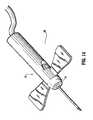
- FIG. 1 is a perspective view of one embodiment of a safety shield apparatus, in accordance with the principals of the present disclosure, with a protective sheath;
- FIG. 2 is a perspective view of the safety shield apparatus shown in FIG. 1, in the extended position with the sheath removed;
- FIG. 3 is a perspective view of the safety shield apparatus shown in FIG. 1, in the retracted position;
- FIG. 4 is a perspective view of the safety shield apparatus shown in FIG. 1, with parts separated;
- FIG. 5 is an orthographic view of a hub of the safety shield apparatus shown in FIG. 1;
- FIG. 6 is a perspective cross section view of the safety shield apparatus shown in FIG. 2;
- FIG. 7 is a perspective view of the indicated area of detail of the safety shield apparatus shown in FIG. 6;
- FIG. 8 is a perspective cross section view of the safety shield apparatus during movement to the retracted position;
- FIG. 9 is a perspective cross section view of the safety shield apparatus shown in FIG. 3;
- FIG. 10 is a side cross section view of an alternate embodiment of the safety shield apparatus shown in FIG. 9;
- FIG. 11 is an orthographic sectional detail view of the indicated area of detail of the safety shield apparatus shown in FIG. 10;
- FIG. 12 is a side cross section view of the hub shown in FIG. 10;
- FIG. 13 is a side view of the safety shield apparatus shown in FIG. 10, in the extended position;
- FIG. 14 is an enlarged perspective view of an alternate embodiment of the safety shield apparatus shown in FIG. 1; and
- FIG. 15 is an enlarged perspective view of another alternate embodiment of the safety shield apparatus shown in FIG. 1.
- The exemplary embodiments of the safety shield apparatus and methods of operation disclosed are discussed in terms of medical needle assemblies for the administration of fluids, and more particularly in terms of a safety shield apparatus that prevents hazardous exposure to a needle. It is contemplated that the needle may be shielded during use including storage, transport, fluid infusion and/or collection, subsequent thereto, etc. It is further contemplated that the safety shield apparatus reduces the occurrence of contaminated needle stick injuries and reduces exposure to pathogens. It is envisioned that the present disclosure, however, finds application with a wide variety of cannula needle devices for the infusion of preventive medications, medicaments, therapeutics, etc., as well as injections employed during procedures relating to phlebotomy, orthopedic, digestive, intestinal, urinary, veterinary types, etc., to a subject. It is also envisioned that the present disclosure may be employed for collection of body fluids including those employed during procedures relating to phlebotomy, digestive, dialysis, intestinal, urinary, veterinary, etc. It is contemplated that the safety shield apparatus may be utilized with other medical needle applications including dental, phlebotomy devices, catheters, catheter introducers, guidewire introducers, spinal, epidural biopsy, aphaeresis, dialysis, blood donor, veress needles, Huber needles, etc. The safety shield apparatus may include winged intravenous needle assemblies.
- In the discussion that follows, the term "proximal" refers to a portion of a structure that is closer to a practitioner and a term "distal" refers to a portion that is further from the practitioner. As used herein the term "subject" refers to a patient that receives infusions or has blood and/or fluid collected therefrom using the safety shield apparatus. According to the present disclosure, the term "practitioner" refers to an individual administering an infusion, performing fluid collection, install or removing a safety shield apparatus and may include support personnel.
- The following discussion includes a description of the safety shield apparatus, followed by a description of an exemplary method of operating a safety shield apparatus in accordance with the principals of the present disclosure. Reference will now be made in detail to the exemplary embodiments and disclosure, which are illustrated with the accompanying figures.
- The component parts of the safety shield apparatus are fabricated from materials suitable for medication injections, such as, for example, polymerics or metals, such as stainless steel, depending on the particular medical needle application and/or preference of a practitioner. Semi-rigid and rigid polymerics are contemplated for fabrication, as well as resilient materials, such as molded medical grade polypropylene. The safety shield apparatus may include transparent materials so that a practitioner can observe flash back to verify the proper location of a needle. One skilled in the art, however, will realize that other materials and fabrication methods suitable for assembly and manufacture, in accordance with the present disclosure, also would be appropriate.
- Turning now to the figures, wherein like components are designated by like reference numerals throughout the several views. Referring initially to FIGS. 1-5, there is illustrated a
safety shield apparatus 20, constructed in accordance with the principals of the present disclosure. Ahousing 22 extends from aproximal end 24 to adistal end 26 and defines a cavity, such as, for example hub retention opening 28 in asidewall 30.Housing 22 may include one or a plurality of cavities.Distal end 26 includes acover 32 having a movable tab such as, for example,outer button 34.Cover 32 may include one or a plurality of movable tabs. - A
needle hub 36 is disposed for movement withinhousing 22.Needle hub 36 includes aneedle cannula 38 having adistal end 40 and a movable projection, such as, for example, compressible bumps 42.Needle hub 36 may include one or a plurality of movable projections.Needle hub 36 is biased between an extended position (FIG. 2), such thatdistal end 40 ofneedle cannula 38 is exposed andcompressible bumps 42 are releasably disposed withinhub retention opening 28, and a retracted position (FIG. 3) wherebydistal end 40 is disposed withinhousing 22.Outer button 34 is engageable withcompressible bumps 42 to releasecompressible bumps 42 from hub retention opening 28 to facilitate movement ofneedle hub 36 to the retracted position. This configuration ofsafety shield apparatus 20 advantageously reduces the occurrence of contaminated needlestick injuries and reduces exposure to pathogens via one-hand operation, as will be discussed, although two handed use is also contemplated. Further,needle cannula 38 can be completely contained inhousing 22 to prevent exposure to the end and sides ofneedle cannula 38, thereby reducing the opportunity for exposure to, for example, blood born pathogens, etc. Safety shield apparatus 20 may include an as shipped position (FIG. 1) whereinneedle hub 36 is in an extended position and ready for use with asheath 44 releasably mounted thereto and enclosingdistal end 40 ofneedle cannula 38. It is contemplatedsheath 44 may fully enclose, partially enclosedistal end 40, or alternatively, thatsafety shield apparatus 20 does not includesheath 44.Safety shield apparatus 20 may include an in use position (FIG. 2), similar to the as shipped position withsheath 44 removed, and a safe position (FIG. 3) whereinneedle hub 36 is in the retracted position. It is envisioned thatsafety shield apparatus 20 may be disposable.- Referring to FIGS. 6 and 7,
housing 22 is elongated and defines a pair of diametrically opposedhub retention openings 28.Housing 22 is substantially transparent and is fabricated from a substantially rigid material.Housing 22 may be monolithically formed. It is contemplated thathousing 22 may extend variable lengths and have various cross-sectional configurations, such as, for example, circular, polygonal, elliptical, etc. It is further contemplated thathousing 22 may be substantially transparent or opaque and formed of a semi-rigid or flexible material, according to the requirements of a particular medical needle application. Hub retention openings 28 have a generally parabolic configuration and are dimensioned for releasable disposal ofcompressible bumps 42 therein.Hub retention openings 28 include an inwarddistal stop 46. Upon disposal ofcompressible bumps 42 withinhub retention openings 28,distal stop 46 defines a clearance withcompressible bumps 42 therebetween.Hub retention openings 28 taper radially outward from inwarddistal stop 46 to outwardproximal end 48. Outwardproximal end 48 is configured to engage and releasably capturecompressible bumps 42 asbumps 42 become disposed withinhub retention openings 28. Outward proximal ends 48 are disposed sufficiently radially outward such that, subsequent to capture ofcompressible bumps 42, bumps 42 may be deflected radially inward and released from engagement with outward proximal ends 48. This releasable configuration advantageously facilitates activation ofsafety shield apparatus 20 to the safe position via one handed operation.- It is envisioned that
hub retention openings 28 may have various configurations and dimensions according to the requirements of a particular medical needle application. It is further envisioned thatdistal stop 46 andproximal end 48 may be disposed at various radial depths and configurations ofhub retention openings 28, including no radial offset ofdistal stop 46 relative toproximal end 48.Hub retention openings 28 may be variously disposed along the length ofhousing 22.Housing 22 defines a rollededge 49 adjacentproximal end 24. Rollededge 49 may be formed during manufacture ofsafety shield apparatus 20 and advantageously eliminates the need for additional components to assemblesafety shield apparatus 20. Housing 22 defines agroove 50 adjacentproximal end 24.Groove 50 is circumferentially disposed about the inner surface ofhousing 22 and is configured for fixed disposal ofcompressible bumps 42, in the retracted position.Groove 50 is recessed within the inner surface ofhousing 22 and defines adistal stop 52.Distal stop 52 projects radially inward fromgroove 50 such that upon disposal ofcompressible bumps 42 withingroove 50, bumps 42 engagedistal stops 52 to irreversibly lockneedle hub 36 in the retracted position.Groove 50 includes aproximal stop 54, similar todistal stop 52, that engages compressible bumps 42.Distal stop 52 prevents distal movement ofneedle hub 36 andproximal stop 54 prevents proximal movement, to facilitate irreversible locking ofsafety shield apparatus 20 and prevent hazardous exposure ofdistal end 40 ofneedle cannula 38. The components ofsafety shield apparatus 20 are not exposed and are contained withinhousing 22 after activation to avoid defeat of the lockout mechanism provided bygroove 50.- It is contemplated that
groove 50 may extend about the entire circumference ofhousing 22 or only a portion thereof. It is further contemplated thatgroove 50 may be configured for releasable locking withneedle hub 36 or thatsafety shield apparatus 20 does not include lockinggroove 50.Groove 50 may be monolithically formed withhousing 22 or integrally mounted therewith via separate structure that may include clips, bands, etc.Groove 50 may be variously disposed about the length ofhousing 22. Cover 32 is separately formed and mounted todistal end 26 ofhousing 22.Outer buttons 34 pivotably extend fromcover 32 in a distal direction.Outer buttons 34 are diametrically disposed oncover 32 corresponding tohub retention openings 28.Outer buttons 34 are oriented to overlapcompressible bumps 42, disposed withinhub retention openings 28, and in substantial alignment withopenings 28.Outer buttons 34 defineinner surface 56 that conforms to the configuration of the outer surface ofcompressible bumps 42. It is contemplated that all or portions ofcover 32 may be monolithically formed withhousing 22. In an alternate embodiment ofsafety shield apparatus 20, as shown in FIG. 14, cover 32 is monolithically formed withhousing 22.Outer buttons 34 are engageable to pivot relative to cover 32 and correspondingly engagecompressible bumps 42. This interactive configuration causescompressible bumps 42 to deflect radially inward and release from capture withhub retention opening 28, as discussed, to facilitate disposal ofsafety shield apparatus 20 in the safe position.- Upon release of
compressible bumps 42 fromhub retention openings 28,outer buttons 34 are free to pivot outwardly and do not interfere with axial movement ofneedle hub 36. This configuration requires engagement or depression of both opposingouter buttons 34. This advantageously prevents false activation due to, for example, inadvertent engagement. This structure also avoids axial disturbance ofsafety shield apparatus 20 that may disturbneedle cannula 38 at the puncture site, which may result in discomfort or injury to a subject. - It is envisioned that
outer buttons 34 may be variously configured and dimensioned. It is further envisioned that the safety features ofsafety shield apparatus 20 may be employed by depressing a single button or a plurality of buttons.Outer buttons 34 may be planar, tapered, etc. for engagement withcompressible bumps 42. Outer buttons 34 are configured to pivot through the radial gap defined betweendistal stop 46 andproximal end 48 ofhub retention opening 28, further preventing false activation ofsafety shield apparatus 20. Alternatively,outer buttons 34 move the distance of the gap before engagingcompressible bumps 42. This further protects against false activation due to inadvertent engagement and reduces sensitivity ofsafety shield apparatus 20.Outer buttons 34 enclosehub retention openings 28 after movement ofneedle hub 36 to the retracted position, further concealingneedle cannula 38 and preventing hazardous exposure.Outer buttons 34 provide concealment forneedle cannula 38 after activation.Outer button 34 may have an easily accessible larger outer surface that, when depressed, projects into hub retention opening 28 to dislodgeneedle hub 36. This configuration facilitates uniform and reliable activation. It is contemplated thatouter buttons 34 may not be required. For example, in an alternate embodiment ofsafety shield apparatus 20, as shown in FIG. 15,housing 22 does not include outer buttons. As such,compressible bumps 42 are directly engageable for release fromhub retention openings 28 to activate safety features ofsafety shield apparatus 20, as discussed herein.Cover 32 includeswings 58 that extend laterally therefrom to facilitate manipulation ofsafety shield apparatus 20.Outer buttons 34 andcompressible bumps 42 may be disposed behindneedle cannula 38, such that whenneedle hub 36 is in the extended position, the activating hand of a practitioner remains positioned behindneedle cannula 38. This feature allows the hands of the practitioner to be positioned behindwings 58 and not repositioned or placed over anunprotected needle cannula 38.Wings 58 may pivotably extend fromhousing 22 and/or be fabricated from a flexible material. It is contemplated that one or a plurality ofwings 58 may be employed. It is further contemplated thatwings 58 may be variably configured and dimensioned, or alternatively, thatsafety shield apparatus 20 may not include wings, according to the requirements of a particular medical needle application.Wings 58 may be variously disposed about the length ofhousing 22.Needle hub 32 is disposed for slidable movement withhousing 22.Needle cannula 38 is mounted to adistal end 60 ofneedle hub 36 and extends therefrom in a distal direction.Distal end 40 ofneedle cannula 38 extends through an opening 62 ofhousing 22 for employment during a medical needle application.- A
coil spring 63 is mounted withinhousing 22 to facilitate axial relative movement ofhousing 22 andneedle hub 36.Coil spring 63 engagesdistal end 60 and a surface ofhousing 22.Coil spring 63 is compressed whenneedle hub 36 is in the extended position and generates a resilient spring force that biases needlehub 36 to the retracted position. This feature ofcoil spring 63 allowssafety shield apparatus 20 to automatically extractneedle cannula 38 and minimize the time an exposed needle may be hazardously exposed. It is envisioned thatneedle hub 36 may create a drag with the inner surface ofhousing 22 during sliding engagement therebetween to slow activation such that alarming noise and recoil may be controlled. In the retracted position,coil spring 63 prevents distal movement ofneedle hub 36 to prevent re-exposure ofdistal end 40 ofneedle cannula 38, thereby avoiding a hazardous condition. It is contemplated thatdistal stop 46 may be configured to engagecompressible bumps 42 and prevent distal movement ofneedle hub 36. - Compressible bumps 42 are diametrically disposed about a
proximal portion 64 ofneedle hub 32 and pivotably extend therefrom. Compressible bumps 42 project radially outward from opposingcantilever members 66 ofneedle hub 36.Cantilever members 66 extend in a proximal direction fromneedle hub 36 and are flexible such thatcompressible bumps 42 are biased radially outward. Ascompressible bumps 42 are depressed radially inward, a resilient spring force is generated incantilever members 66 causing a resilient bias ofcompressible bumps 42 radially outward. This configuration facilitates disposal ofcompressible bumps 42 within for example,hub retention openings 28 andgroove 50. - Thus, by manipulating
safety shield apparatus 20 to squeeze or pinch the opposingouter buttons 34 andcompressible bumps 42, some of the safety features that encloseneedle cannula 38 inhousing 22 are activated. The opposingouter buttons 34 andcompressible bumps 42 can be simultaneously depressed to provide protection against false activation. The opposing position ofouter buttons 34 andcompressible bumps 42 provides a comfortable, natural motion to activate the safety features. This "pinching" motion also does not require the user to force the safety shield apparatus to move rearward in a manner that could cause further discomfort or injury at the puncture site. Activation of opposingouter buttons 34 andcompressible bumps 42 may be alternatively facilitated by axial force, flip switch, etc. Cantilever members 66 cooperate to define ahub cavity 68. Anextension 70 projects proximally withinhub cavity 68 for connection to afirst end 72 oftransfer tubing 74.Transfer tubing 74 provides a flexible fluid path in fluid communication withneedle cannula 38.Transfer tubing 74 is substantially transparent to facilitate visualization of fluid flow therein, such as, for example, flashback.- A
second end 76 oftransfer tubing 74 is attached with aluer connector 78.Luer connector 78 is attached to a fluid administration apparatus (not shown) that is in fluid communication withneedle cannula 38 viatransfer tubing 74.Luer connector 78 facilitates interface with a variety of fluid circuits. It is contemplated thatsafety shield apparatus 20 may be employed with various fluid administration apparatus such as, for example, syringes, dental devices, phlebotomy devices, catheters, catheter introducers, guidewire introducers, biopsy devices, dialysis devices, etc. - Referring to FIGS. 10-12, an alternate embodiment of
safety shield apparatus 20 is shown, similar to that described.Distal end 26 ofhousing 22 includes a rigidtransverse wall 100 that defines anopening 102 for passage ofneedle cannula 38.Transverse wall 100 further defines acircumferential lip 104 disposed about opening 102.Lip 104 is configured to capturedistal end 40 ofneedle cannula 38, in the retracted position ofneedle hub 36, as shown in FIG. 10. It is contemplated thatlip 104 may be disposed about all or, alternatively, only a portion ofopening 102.Opening 102 is configured to receive and slidablysupport needle hub 36. The surface of opening 102 engagesdistal end 60 ofneedle hub 36 to advantageously provide stability during operation ofsafety shield apparatus 20. - Capturing
distal end 40 ofneedle cannula 38 behindtransverse wall 100 andlip 104, relative to opening 102, prevents exposure ofdistal end 40 by increasing the force required to overcome the safe condition ofsafety needle apparatus 20, as shown in FIG. 10. Needle cannula 38 is oriented into a position for capture ofdistal end 40 due to the configuration ofneedle hub 36.Needle hub 36 defines an angleddistal surface 106.Distal surface 106 is oriented at an angle α, which is measured from a plane transverse to a longitudinal axis x ofsafety shield apparatus 20. It is envisioned that angle α may include various degrees of inclination, according to the requirements of a particular medical needle application. Other structure may be employed withsafety shield apparatus 20 for orientingneedle cannula 38 into a capture position, such as, for example, pivot structure, ball joint, etc.- In the extended position,
needle cannula 38 extends from housing 22 (not shown) and orientsneedle cannula 38 in substantial alignment with longitudinal axis x ofhousing 22.Coil spring 63 engages angleddistal surface 106 and the inner surface ofhousing 22.Coil spring 63 is compressed and generates a resilient spring force that biases needlehub 32 to the retracted position, similar to that discussed. In an alternate embodiment, as shown in FIG. 13, in the extended position,needle cannula 38 extends fromhousing 22 and orientsneedle cannula 38 out of alignment with longitudinal axis x ofhousing 22. This configuration results in a non-axial needle alignment that reduces stress on the puncture site of a subject by allowingsafety shield apparatus 20 to lay flatter when taped down to the subject. Outer buttons 34 andcompressible bumps 42 are manipulated to activate some of the safety features ofsafety shield apparatus 20, as discussed, andneedle hub 36 is forced to the retracted position. In the retracted position, as shown in FIG. 10,coil spring 63 engagestransverse wall 100 and angleddistal surface 106 onneedle hub 36 to orientneedle cannula 38 out of axial alignment with longitudinal axis x ofhousing 22 and into capture withlip 104.- Angled
distal surface 106 biases needlecannula 38 towardside wall 30 ofhousing 22 due to pressure applied to surface 106 fromcoil spring 63. It is contemplated thatneedle cannula 38 may be mounted withneedle hub 36 at an inclination that directsdistal end 40 towardside wall 30. Other structure that inclinedistal end 40 behindlip 104 are also contemplated. The non-alignment ofneedle cannula 38 advantageously provides increased difficulty when attempts are made to defeat locking ofsafety shield apparatus 20. Cover 32 is mounted todistal end 26 ofhousing 22 such that afluid chamber 108 is formed therebetween.Fluid chamber 108 is configured to contain fluid and may be variously dimensioned according to the requirements of a particular medical needle application. For example, contaminated fluids may accumulate on the outer surface ofneedle cannula 38.Fluid chamber 108 facilitates containment by collecting such fluids from the outer surface ofneedle cannula 38.Cover 32 defines anopening 110 that is larger in diameter than opening 102.Openings fluid chamber 108.Opening 102 is smaller than opening 110 such thatneedle cannula 38 only engagesopening 102. Thus, fluid is scraped fromneedle cannula 38 by the edges ofopening 102 and collects influid chamber 108.- Referring to FIGS. 1-3,
safety shield apparatus 22, similar to that described above, is assembled, sterilized and packaged for use. In operation,safety shield apparatus 20 is removed from a package. First end 72 ofintravenous transfer tubing 74 is connected toextension 70 ofsafety shield apparatus 20.Second end 76 oftubing 74, includingluer connector 78, is connected to an appropriate fluid circuit of a fluid administration apparatus (not shown).Sheath 44 is removed fromsafety shield apparatus 20. Needle cannula 38 is inserted into a vessel (not shown) of a subject and a medical needle procedure is performed to completion.Safety shield apparatus 20 may be taped down onto the subject and removed upon completion of the medical needle procedure. It is envisioned that upon completion of the medical needle procedure the practitioner places absorbent material over the injection site with one hand and positions a second hand to graspwings 58 for removal ofsafety shield apparatus 20.Safety shield apparatus 20 extracts needlecannula 38 from the subject andneedle hub 36 is in the retracted position, as shown in FIGS. 2 and 6. The safety features ofsafety shield apparatus 20 are initiated by pinching opposingouter buttons 34 between a thumb and finger of the practitioner causingcompressible bumps 42 onneedle hub 36 to dislodge fromhub retention openings 28 ofhousing 22, as discussed and shown in FIG. 8.Coil spring 63 forces needlehub 36,needle cannula 38 andtransfer tubing 74 proximally until the locking features ofsafety shield apparatus 20, discussed above, are activated, and create an irreversibly locked or safe condition, as shown in FIGS. 3 and 9.Safety shield apparatus 20 may be discarded. Other methods of use are also contemplated.- It will be understood that various modifications may be made to the embodiments disclosed herein. Therefore, the above description should not be construed as limiting, but merely as exemplification of the various embodiments. Those skilled in the art will envision other modifications within the scope of the claims appended hereto.
Claims (18)
- A safety shield apparatus (20) comprising:a housing (22) having a proximal end (24) and a distal end (26) and defining a plurality of cavities (28) in a side wall (30) thereof; anda hub (36) disposed for movement within the housing (22), the hub (36) including a needle (38) having a distal end (40) and a plurality of movable projections (42),wherein the hub (36) is biased from an extended position in which the distal end of the needle (40) is exposed and each of the movable projections (42) is releasably disposed within a corresponding one of the plurality of cavities (28), to a retracted position in which the distal end of the needle (40) is disposed within the housing (22),characterized in that the distal end (26) of the housing (22) including a cover (32) having a plurality of moveable tabs (34) and wherein the movable tabs (34) are engageable with the movable projections (42) to release the movable projections (42) from the cavities (28) to facilitate movement of the hub (36) to the retracted position.
- A safety shield apparatus (20) as recited in claim 1, wherein the proximal end (24) of the housing (22) defines a groove (50) on an inner surface thereof that is configured for fixed disposal of the plurality of movable projections (42), in the retracted position.
- A safety shield apparatus (20) as recited in claim 1, wherein the housing (22) is substantially rigid.
- A safety shield apparatus (20) as recited in claim 1, wherein the cover (32) is separately formed and mounted to the distal end (26) of the housing (22).
- A safety shield apparatus (20) as recited in claim 4, wherein the cover (32) is mounted with the distal end (26) of the housing such that a chamber (108) is formed therebetween.
- A safety shield apparatus (20) as recited in claim 1, wherein the housing (22) is monolithically formed.
- A safety shield apparatus (20) as recited in claim 1, wherein the plurality of movable tabs (34) extend from the cover (32) for pivotable movement relative thereto.
- A safety shield apparatus (20) as recited in claim 1, wherein the plurality of movable projections (42) pivotably extend from the hub (36) and are biased radially outward.
- A safety shield apparatus (20) as recited in claim 1, wherein the hub (36) is biased for movement within the housing (22) via a biasing member supported between the hub (36) and the distal end (26) of the housing (22).
- A safety shield apparatus (20) as recited in claim 1, wherein the distal end (26) of the housing (22) includes a rigid transverse wall (100) that defines an opening (102) for passage of the needle (38), the transverse wall (100) further defining a lip (104) disposed about the opening that is configured to capture the distal end (40) of the needle (38), in the retracted position.
- A safety shield apparatus (20) as recited in claim 10, wherein the hub (36) defines an angled distal surface (106) that engages the biasing member disposed between the hub (36) and the distal end (26) of the housing (22) such that, in the retracted position, the hub (36) orients the needle (38) out of axial alignment with the housing (22) and into capture with the lip (104).
- A safety shield apparatus (20) as recited in claim 9, wherein the cover (32) includes a wing (58) extending therefrom for manipulation of the housing (22).
- A safety shield apparatus (20) as recited in claim 9, wherein the proximal end (24) of the housing (22) defines a groove (50) circumferentially disposed about an inner surface thereof that is configured for fixed engagement with the plurality of moveable projections (42).
- A safety shield apparatus (20) as recited in claim 9, wherein the biasing member is a coil spring (63) disposed about the needle.
- A safety shield apparatus (20) as recited in claim 9, wherein the distal end (26) of the housing (22) includes a rigid transverse wall (100) that defines an opening (102) for passage of the needle (38), the transverse wall (100) further defining a lip (104) disposed about the opening that is configured to capture the distal end (40) of the needle (38), in the retracted position.
- A safety shield apparatus (20) as recited in claim 15, wherein the hub (36) defines an angled distal surface (106) that engages the biasing member such that, in the retracted position, the hub (36) orients the needle (38) out of axial alignment with the housing (22) and into capture with the lip (104).
- A safety shield apparatus (20) as recited in claim 9, wherein the cover (32) is mounted with the distal end (26) of the housing (22) such that a fluid chamber (108) is formed therebetween.
- A safety shield apparatus (20) as recited in claim 9, further including tubing (74) having a first end (72) being attached to a proximal end of the hub (36) and in fluid communication with the needle (38), a second end (76) of the tubing being attached to a fluid administration apparatus and in fluid communication therewith.
Applications Claiming Priority (2)
| Application Number | Priority Date | Filing Date | Title |
|---|---|---|---|
| US10/609,304US7037292B2 (en) | 2003-06-27 | 2003-06-27 | Safety needle shield apparatus |
| PCT/US2004/020975WO2005000387A1 (en) | 2003-06-27 | 2004-06-28 | Safety needle shield apparatus |
Publications (2)
| Publication Number | Publication Date |
|---|---|
| EP1638637A1 EP1638637A1 (en) | 2006-03-29 |
| EP1638637B1true EP1638637B1 (en) | 2007-08-15 |
Family
ID=33540840
Family Applications (1)
| Application Number | Title | Priority Date | Filing Date |
|---|---|---|---|
| EP04777300AExpired - LifetimeEP1638637B1 (en) | 2003-06-27 | 2004-06-28 | Safety needle shield apparatus |
Country Status (10)
| Country | Link |
|---|---|
| US (3) | US7037292B2 (en) |
| EP (1) | EP1638637B1 (en) |
| JP (2) | JP5038713B2 (en) |
| CN (1) | CN1842353B (en) |
| AT (1) | ATE369889T1 (en) |
| AU (1) | AU2004251782B2 (en) |
| CA (1) | CA2529946C (en) |
| DE (1) | DE602004008279T2 (en) |
| ES (1) | ES2290765T3 (en) |
| WO (1) | WO2005000387A1 (en) |
Families Citing this family (70)
| Publication number | Priority date | Publication date | Assignee | Title |
|---|---|---|---|---|
| JP3347767B2 (en) | 1992-07-10 | 2002-11-20 | フロイント産業株式会社 | Bread coating equipment |
| JP2894548B2 (en) | 1995-09-07 | 1999-05-24 | 東和工機株式会社 | Small article dryer |
| US7037292B2 (en)* | 2003-06-27 | 2006-05-02 | Sherwood Services Ag | Safety needle shield apparatus |
| US7490295B2 (en) | 2004-06-25 | 2009-02-10 | Apple Inc. | Layer for accessing user interface elements |
| US7905857B2 (en) | 2005-07-11 | 2011-03-15 | Covidien Ag | Needle assembly including obturator with safety reset |
| US7850650B2 (en) | 2005-07-11 | 2010-12-14 | Covidien Ag | Needle safety shield with reset |
| US7828773B2 (en) | 2005-07-11 | 2010-11-09 | Covidien Ag | Safety reset key and needle assembly |
| US20060135910A1 (en)* | 2004-12-17 | 2006-06-22 | Luther Ronald B | Percutaneous safety needle inserter |
| US20060276747A1 (en) | 2005-06-06 | 2006-12-07 | Sherwood Services Ag | Needle assembly with removable depth stop |
| US7731692B2 (en) | 2005-07-11 | 2010-06-08 | Covidien Ag | Device for shielding a sharp tip of a cannula and method of using the same |
| US7753878B2 (en)* | 2005-09-22 | 2010-07-13 | Tyco Healthcare Group Lp | Safety needle with lockout mechanism |
| JP2009520508A (en)* | 2005-09-22 | 2009-05-28 | タイコ・ヘルスケアー・グループ・エルピー | Manual retractable safety needle with rigid blade structure |
| AU2006295443B2 (en)* | 2005-09-22 | 2012-03-29 | Kpr U.S., Llc | Needle retraction structure |
| AU2006292108B2 (en) | 2005-09-22 | 2012-08-02 | Kpr U.S., Llc | Non-axial return spring for safety needle |
| US7654735B2 (en) | 2005-11-03 | 2010-02-02 | Covidien Ag | Electronic thermometer |
| JP4890952B2 (en)* | 2006-06-12 | 2012-03-07 | 株式会社トップ | Indwelling needle |
| JP4994775B2 (en) | 2006-10-12 | 2012-08-08 | 日本コヴィディエン株式会社 | Needle point protector |
| US8888713B2 (en) | 2007-03-07 | 2014-11-18 | Becton, Dickinson And Company | Safety blood collection assembly with indicator |
| EP3108812B1 (en)* | 2007-03-07 | 2020-04-29 | Becton, Dickinson and Company | Safety blood collection assembly with indicator |
| US20080287869A1 (en)* | 2007-05-17 | 2008-11-20 | Thomas Chun | Safety Syringe |
| US8419763B2 (en)* | 2007-09-13 | 2013-04-16 | Pivot Medical, Inc. | Safety needle for accessing the interior of a hip joint |
| US8357104B2 (en) | 2007-11-01 | 2013-01-22 | Coviden Lp | Active stylet safety shield |
| JP5257652B2 (en)* | 2008-02-22 | 2013-08-07 | 株式会社トップ | Medical needle with protector |
| US8795198B2 (en) | 2008-03-07 | 2014-08-05 | Becton, Dickinson And Company | Flashback blood collection needle |
| US8603009B2 (en) | 2008-03-07 | 2013-12-10 | Becton, Dickinson And Company | Flashback blood collection needle |
| US9259533B2 (en)* | 2008-03-31 | 2016-02-16 | Covidien Lp | Safety needle with spring biased retraction mechanism |
| US8708969B2 (en)* | 2008-06-30 | 2014-04-29 | Covidien Lp | Safety device actuation system |
| US8951228B2 (en)* | 2009-03-12 | 2015-02-10 | Stat Medical Devices, Inc. | IV infusion system device having retractable needle and method of making and using the same |
| US9044552B2 (en)* | 2009-04-08 | 2015-06-02 | Stat Medical Devices, Inc. | Needle safety system and method |
| CN104027868B (en)* | 2009-07-20 | 2017-04-12 | B·布劳恩医药工业有限公司 | Safety needle assembly and methods |
| AU2011210883A1 (en)* | 2010-02-01 | 2012-08-23 | Mark Banister | Angiocatheter device with improved safety features |
| EP2946804B1 (en)* | 2010-09-07 | 2017-11-22 | Poly Medicure Limited | Needle protector assembly |
| ES2662356T3 (en) | 2011-04-27 | 2018-04-06 | Kpr U.S., Llc | Safety IV catheter assemblies |
| US8591467B2 (en) | 2011-07-25 | 2013-11-26 | Covidien Lp | Vascular access assembly and safety device |
| EP2760521B1 (en) | 2011-09-26 | 2016-01-06 | Covidien LP | Safety iv catheter and needle assembly |
| WO2013048975A1 (en) | 2011-09-26 | 2013-04-04 | Covidien Lp | Safety catheter |
| US8834422B2 (en) | 2011-10-14 | 2014-09-16 | Covidien Lp | Vascular access assembly and safety device |
| CN103371833A (en)* | 2012-04-28 | 2013-10-30 | 崔明 | Disposable safety blood-sampling needle |
| CN103372246A (en)* | 2012-04-28 | 2013-10-30 | 崔明 | Disposable safety infusion needle |
| CN103372243A (en)* | 2012-04-28 | 2013-10-30 | 崔明 | Disposable safety infusion set |
| WO2014121119A1 (en) | 2013-02-01 | 2014-08-07 | Nxstage Medical, Inc. | Safe cannulation devices, methods, and systems |
| MX370463B (en) | 2013-10-10 | 2019-12-13 | Medical Components Inc | Huber needle assembly with safety capture device. |
| EP3171810A4 (en)* | 2014-07-24 | 2018-03-14 | Noble House Group Pty. Ltd. | Needle guard |
| MX2017002698A (en) | 2014-08-29 | 2017-05-23 | Medical Components Inc | Huber safety needle. |
| USD804021S1 (en) | 2015-02-27 | 2017-11-28 | Medical Components, Inc. | Huber safety needle |
| USD804022S1 (en) | 2015-02-27 | 2017-11-28 | Medical Components, Inc. | Huber safety needle |
| JP6867101B2 (en)* | 2015-08-21 | 2021-04-28 | ニプロ株式会社 | Indwelling needle |
| WO2017033449A1 (en)* | 2015-08-24 | 2017-03-02 | ニプロ株式会社 | Indwelling needle |
| EP3380157B1 (en)* | 2015-11-25 | 2021-07-21 | Bayer Healthcare LLC | Syringe tip with fluid wicking drip flanges |
| AU2017234800B2 (en) | 2016-03-18 | 2020-09-17 | Medical Components, Inc. | Huber safety needle |
| KR102508054B1 (en)* | 2016-04-12 | 2023-03-10 | 주식회사 인성메디칼 | Safe needle assembly for catheter |
| WO2017209304A1 (en)* | 2016-06-03 | 2017-12-07 | ニプロ株式会社 | Needlepoint protector for indwelling needle and indwelling needle assembly |
| CA3030011A1 (en)* | 2016-07-19 | 2018-01-25 | Shifamed Holdings, Llc | Medical devices and methods of use |
| AU2018231164B2 (en) | 2017-03-06 | 2020-10-15 | Icu Medical, Inc. | Blood containment for IV catheter |
| EP3573695A4 (en) | 2017-03-06 | 2020-10-28 | Smiths Medical ASD, Inc. | IV CATHETER WITH VEIN ENTRY INDICATOR |
| EP3568185A4 (en) | 2017-03-06 | 2020-10-28 | Smiths Medical ASD, Inc. | CATHETER INSERTION DEVICE WITH TIP PROTECTION HOUSING |
| JP2020528781A (en)* | 2017-07-25 | 2020-10-01 | クリン インコーポレイテッド | Needle assembly with needle safety shield |
| IT201700103120A1 (en)* | 2017-09-14 | 2019-03-14 | Sol Millennium Swiss R&D Center Sa | MEDICAL DEVICE PERFECTED WITH SAFETY NEEDLE WITH ELASTIC RETRACTION |
| IT201900001685A1 (en)* | 2019-02-06 | 2020-08-06 | Sol Millennium Swiss R&D Center Sa | MEDICAL DEVICE WITH OFFSET CANNULA |
| US11590293B2 (en) | 2019-02-21 | 2023-02-28 | Khaled Boubes | Locking hemodialysis needle assembly with integral needle tip protector |
| USD884160S1 (en) | 2019-02-25 | 2020-05-12 | iMed Technology, Inc. | Huber safety needle |
| WO2020181229A1 (en) | 2019-03-07 | 2020-09-10 | Smiths Medical Asd, Inc. | Catheter insertion device with improved flashback response |
| CA3169051A1 (en) | 2019-09-10 | 2021-03-18 | Medsource International Llc | An intravenous catheter device |
| JP6760472B2 (en)* | 2019-10-30 | 2020-09-23 | ニプロ株式会社 | Indwelling needle |
| US11850409B2 (en)* | 2020-04-23 | 2023-12-26 | Kawasumi Laboratories, Inc. | Medical needle |
| JPWO2022034904A1 (en) | 2020-08-14 | 2022-02-17 | ||
| JP2021028045A (en)* | 2020-11-30 | 2021-02-25 | ニプロ株式会社 | Indwelling needle |
| US12337123B2 (en) | 2021-05-06 | 2025-06-24 | Medsource Labs, Llc | Safety intravenous cannula |
| US12186497B2 (en) | 2022-01-14 | 2025-01-07 | Medsource International Llc | Intravenous cannula |
| CN119136737A (en)* | 2022-04-08 | 2024-12-13 | 贝克顿·迪金森公司 | Arterial blood gas syringe |
Family Cites Families (55)
| Publication number | Priority date | Publication date | Assignee | Title |
|---|---|---|---|---|
| US4183246A (en)* | 1978-06-08 | 1980-01-15 | Reynolds Steven C | Insulation presence sensing probe |
| GB8519049D0 (en)* | 1985-07-29 | 1985-09-04 | Bryne P O | Safety device |
| US4676783A (en)* | 1985-09-03 | 1987-06-30 | The University Of Virginia Alumni Patents Foundation | Retractable safety needle |
| US4767413A (en)* | 1987-04-20 | 1988-08-30 | Habley Medical Technology Corporation | Dental syringe having an automatically retractable needle |
| US4900307A (en)* | 1987-04-29 | 1990-02-13 | Kulli John C | Safety retracting needle for use with syringe |
| US4747831A (en)* | 1987-04-29 | 1988-05-31 | Phase Medical, Inc. | Cannula insertion set with safety retracting needle |
| US4813426A (en)* | 1987-11-09 | 1989-03-21 | Habley Medical Technology Corporation | Shielded safety syringe having a retractable needle |
| US5085639A (en)* | 1988-03-01 | 1992-02-04 | Ryan Medical, Inc. | Safety winged needle medical devices |
| JP2647132B2 (en) | 1988-04-28 | 1997-08-27 | シー.クリー ジョン | Cannula insertion device with safety retraction needle |
| US4900311A (en)* | 1988-12-06 | 1990-02-13 | Lawrence Stern | Hypodermic syringe |
| US6096005A (en)* | 1989-07-11 | 2000-08-01 | Mdc Investment Holdings, Inc. | Retractable needle medical devices |
| US5000167A (en)* | 1989-08-03 | 1991-03-19 | Sherwood Medical Company | Blood collection tube holder safety guard |
| US4978343A (en)* | 1990-01-16 | 1990-12-18 | Dysarz Edward D | Trap in barrel one handed retractable safety syringe |
| US5129884A (en)* | 1990-01-16 | 1992-07-14 | Dysarz Edward D | Trap in barrel one handed retracted intervenous catheter device |
| US5624400A (en)* | 1990-05-09 | 1997-04-29 | Safety Syringes, Inc. | Disposable self-shielding aspirating syringe |
| US5226894A (en)* | 1990-09-11 | 1993-07-13 | Sterling Winthrop Inc. | Safety syringe assembly with radially deformable body |
| US5176655A (en)* | 1990-11-08 | 1993-01-05 | Mbo Laboratories, Inc. | Disposable medical needle and catheter placement assembly having full safety enclosure means |
| US5108376A (en)* | 1990-11-14 | 1992-04-28 | Safetyject | Retractable intravenous needle assembly |
| US5273540A (en)* | 1991-04-26 | 1993-12-28 | Luther Medical Products | Nonreusable needle and catheter assembly |
| ES1017717Y (en)* | 1991-05-30 | 1993-12-16 | Serrano Gonzalez | SELF-RETRACTILE HYPODERMIC NEEDLE PROTECTOR. |
| US5211629A (en) | 1991-12-23 | 1993-05-18 | Pressly William B S | Safety syringe |
| US5201708A (en)* | 1992-02-03 | 1993-04-13 | Timothy A. Kershenstine | Self-locking safety syringe |
| DK0606459T3 (en)* | 1992-07-31 | 2001-08-13 | Luckhurst Anthony Henry Willia | Needle Protection Device |
| US5338303A (en)* | 1992-09-08 | 1994-08-16 | Design And Engineering Associates | Safety syringes |
| US5368568A (en) | 1993-10-12 | 1994-11-29 | Pitts; Raymond H. | Disabling hypodermic syringe |
| US5573510A (en)* | 1994-02-28 | 1996-11-12 | Isaacson; Dennis R. | Safety intravenous catheter assembly with automatically retractable needle |
| CA2168615A1 (en)* | 1995-03-07 | 1996-09-08 | Timothy J. Erskine | Catheter-advancement actuated needle retraction system |
| US5554130A (en)* | 1995-05-17 | 1996-09-10 | Creative Bio Tech, Inc. | Stick-free syringe and associated methods |
| US5591138A (en)* | 1995-08-10 | 1997-01-07 | Vaillancourt; Vincent L. | Protected needle assembly |
| US5695475A (en)* | 1995-12-13 | 1997-12-09 | Best, Jr.; Lester | Syringe apparatus |
| GB9610682D0 (en)* | 1996-05-22 | 1996-07-31 | Boc Group Plc | Medical devices |
| JP3134920B2 (en)* | 1996-09-20 | 2001-02-13 | 株式会社ニッショー | Indwelling needle with wing |
| US5746215A (en)* | 1996-11-01 | 1998-05-05 | U.S. Medical Instruments, Inc. | IV infusion or collection device with extendable and retractable needle |
| US6080137A (en)* | 1997-01-08 | 2000-06-27 | Vadus, Inc. | Needle protector |
| DE69828621T2 (en)* | 1997-03-26 | 2005-06-16 | Bio-Plexus, Inc., Vernon | DEVICE FOR TRANSFERING A PARENTERAL LIQUID |
| US5779679A (en)* | 1997-04-18 | 1998-07-14 | Shaw; Thomas J. | Winged IV set with retractable needle |
| US6090078A (en)* | 1997-09-30 | 2000-07-18 | Becton, Dickinson And Company | Dampening devices and methods for needle retracting safety vascular access devices |
| US5964739A (en) | 1998-06-18 | 1999-10-12 | Champ; Raynido A. | Safety disposable needle structure |
| US6547762B1 (en)* | 1999-05-13 | 2003-04-15 | Mdc Investment Holdings, Inc. | Retractable needle medical device |
| WO2000047256A1 (en) | 1999-02-15 | 2000-08-17 | Syringe Development Partners L.L.C. | Retractable i-v catheter placement device |
| US6210371B1 (en)* | 1999-03-30 | 2001-04-03 | Retractable Technologies, Inc. | Winged I.V. set |
| US6368303B1 (en)* | 1999-10-15 | 2002-04-09 | Becton, Dickinson And Company | Retracting needle syringe |
| US6776775B1 (en)* | 1999-12-23 | 2004-08-17 | Owais Mohammad | Hypodermic syringe needle assembly and method of making the same |
| GB0003790D0 (en) | 2000-02-18 | 2000-04-05 | Astrazeneca Uk Ltd | Medical device |
| CN1523970A (en)* | 2000-04-18 | 2004-08-25 | Mdc投资控股公司 | Medical device with retractable needle shield |
| US6972002B2 (en)* | 2000-04-28 | 2005-12-06 | Specialized Health Products, Inc. | Passively activated safety shield for a catheter insertion needle |
| US6524276B1 (en) | 2000-06-05 | 2003-02-25 | Mdc Investment Holdings, Inc. | Fluid collection device having tilting retractable needle |
| US20040193110A1 (en)* | 2002-02-07 | 2004-09-30 | Lucio Giambattista | Pen needle and safety shield system |
| US6743186B2 (en) | 2001-01-05 | 2004-06-01 | Becton, Dickinson And Company | Blood collection assembly |
| JP2004538103A (en)* | 2001-08-09 | 2004-12-24 | ベクトン・ディキンソン・アンド・カンパニー | Retractable safety needle device |
| US7294118B2 (en)* | 2001-10-24 | 2007-11-13 | Becton, Dickinson And Company | Retractable needle assembly |
| US6784875B2 (en)* | 2002-01-11 | 2004-08-31 | Symbol Technologies, Inc. | Ruggedized, water sealed, security-enhanced touchpad assembly |
| US6976976B2 (en)* | 2002-03-27 | 2005-12-20 | Safety Syringes, Inc. | Syringe with needle guard injection device |
| US7300421B1 (en) | 2002-11-26 | 2007-11-27 | Suzanne L. Lowry | Safety syringe and safety syringe adapter |
| US7037292B2 (en) | 2003-06-27 | 2006-05-02 | Sherwood Services Ag | Safety needle shield apparatus |
- 2003
- 2003-06-27USUS10/609,304patent/US7037292B2/ennot_activeExpired - Lifetime
- 2004
- 2004-06-28ATAT04777300Tpatent/ATE369889T1/ennot_activeIP Right Cessation
- 2004-06-28DEDE602004008279Tpatent/DE602004008279T2/ennot_activeExpired - Lifetime
- 2004-06-28CACA2529946Apatent/CA2529946C/ennot_activeExpired - Fee Related
- 2004-06-28ESES04777300Tpatent/ES2290765T3/ennot_activeExpired - Lifetime
- 2004-06-28EPEP04777300Apatent/EP1638637B1/ennot_activeExpired - Lifetime
- 2004-06-28AUAU2004251782Apatent/AU2004251782B2/ennot_activeCeased
- 2004-06-28WOPCT/US2004/020975patent/WO2005000387A1/enactiveIP Right Grant
- 2004-06-28JPJP2006517791Apatent/JP5038713B2/ennot_activeExpired - Fee Related
- 2004-06-28CNCN2004800245145Apatent/CN1842353B/ennot_activeExpired - Fee Related
- 2006
- 2006-01-30USUS11/343,825patent/US8486015B2/ennot_activeExpired - Fee Related
- 2010
- 2010-06-29JPJP2010147957Apatent/JP5094919B2/ennot_activeExpired - Fee Related
- 2013
- 2013-07-01USUS13/932,390patent/US9504786B2/ennot_activeExpired - Lifetime
Also Published As
| Publication number | Publication date |
|---|---|
| CN1842353B (en) | 2010-09-22 |
| JP5094919B2 (en) | 2012-12-12 |
| US8486015B2 (en) | 2013-07-16 |
| JP2007521080A (en) | 2007-08-02 |
| US7037292B2 (en) | 2006-05-02 |
| CA2529946C (en) | 2013-01-08 |
| AU2004251782B2 (en) | 2008-12-04 |
| ATE369889T1 (en) | 2007-09-15 |
| DE602004008279T2 (en) | 2008-05-15 |
| US20040267200A1 (en) | 2004-12-30 |
| CA2529946A1 (en) | 2005-01-06 |
| US20140018740A1 (en) | 2014-01-16 |
| AU2004251782A1 (en) | 2005-01-06 |
| ES2290765T3 (en) | 2008-02-16 |
| EP1638637A1 (en) | 2006-03-29 |
| US20060189936A1 (en) | 2006-08-24 |
| WO2005000387A1 (en) | 2005-01-06 |
| CN1842353A (en) | 2006-10-04 |
| DE602004008279D1 (en) | 2007-09-27 |
| JP2010207634A (en) | 2010-09-24 |
| JP5038713B2 (en) | 2012-10-03 |
| US9504786B2 (en) | 2016-11-29 |
Similar Documents
| Publication | Publication Date | Title |
|---|---|---|
| EP1638637B1 (en) | Safety needle shield apparatus | |
| CA2540483C (en) | Safety shield | |
| US6936036B2 (en) | Blood collection agency | |
| US8133207B2 (en) | Passive activated safety blood collection set | |
| EP1926513B1 (en) | Non-axial return spring for safety needle | |
| US6485469B1 (en) | Shielded dental safety needle | |
| US6926700B2 (en) | Needle assembly | |
| US6945958B2 (en) | Safety needle apparatus | |
| US8241254B2 (en) | Medical needle systems with reset devices for medical needle shield apparatus |
Legal Events
| Date | Code | Title | Description |
|---|---|---|---|
| PUAI | Public reference made under article 153(3) epc to a published international application that has entered the european phase | Free format text:ORIGINAL CODE: 0009012 | |
| 17P | Request for examination filed | Effective date:20051220 | |
| AK | Designated contracting states | Kind code of ref document:A1 Designated state(s):AT BE BG CH CY CZ DE DK EE ES FI FR GB GR HU IE IT LI LU MC NL PL PT RO SE SI SK TR | |
| 17Q | First examination report despatched | Effective date:20060626 | |
| DAX | Request for extension of the european patent (deleted) | ||
| GRAP | Despatch of communication of intention to grant a patent | Free format text:ORIGINAL CODE: EPIDOSNIGR1 | |
| RAP1 | Party data changed (applicant data changed or rights of an application transferred) | Owner name:COVIDIEN AG | |
| GRAS | Grant fee paid | Free format text:ORIGINAL CODE: EPIDOSNIGR3 | |
| GRAA | (expected) grant | Free format text:ORIGINAL CODE: 0009210 | |
| AK | Designated contracting states | Kind code of ref document:B1 Designated state(s):AT BE BG CH CY CZ DE DK EE ES FI FR GB GR HU IE IT LI LU MC NL PL PT RO SE SI SK TR | |
| REG | Reference to a national code | Ref country code:GB Ref legal event code:FG4D | |
| REG | Reference to a national code | Ref country code:CH Ref legal event code:EP | |
| REG | Reference to a national code | Ref country code:IE Ref legal event code:FG4D | |
| REF | Corresponds to: | Ref document number:602004008279 Country of ref document:DE Date of ref document:20070927 Kind code of ref document:P | |
| PG25 | Lapsed in a contracting state [announced via postgrant information from national office to epo] | Ref country code:NL Free format text:LAPSE BECAUSE OF FAILURE TO SUBMIT A TRANSLATION OF THE DESCRIPTION OR TO PAY THE FEE WITHIN THE PRESCRIBED TIME-LIMIT Effective date:20070815 Ref country code:FI Free format text:LAPSE BECAUSE OF FAILURE TO SUBMIT A TRANSLATION OF THE DESCRIPTION OR TO PAY THE FEE WITHIN THE PRESCRIBED TIME-LIMIT Effective date:20070815 Ref country code:BG Free format text:LAPSE BECAUSE OF FAILURE TO SUBMIT A TRANSLATION OF THE DESCRIPTION OR TO PAY THE FEE WITHIN THE PRESCRIBED TIME-LIMIT Effective date:20071115 | |
| NLV1 | Nl: lapsed or annulled due to failure to fulfill the requirements of art. 29p and 29m of the patents act | ||
| REG | Reference to a national code | Ref country code:ES Ref legal event code:FG2A Ref document number:2290765 Country of ref document:ES Kind code of ref document:T3 | |
| PG25 | Lapsed in a contracting state [announced via postgrant information from national office to epo] | Ref country code:PL Free format text:LAPSE BECAUSE OF FAILURE TO SUBMIT A TRANSLATION OF THE DESCRIPTION OR TO PAY THE FEE WITHIN THE PRESCRIBED TIME-LIMIT Effective date:20070815 Ref country code:CH Free format text:LAPSE BECAUSE OF FAILURE TO SUBMIT A TRANSLATION OF THE DESCRIPTION OR TO PAY THE FEE WITHIN THE PRESCRIBED TIME-LIMIT Effective date:20070815 Ref country code:AT Free format text:LAPSE BECAUSE OF FAILURE TO SUBMIT A TRANSLATION OF THE DESCRIPTION OR TO PAY THE FEE WITHIN THE PRESCRIBED TIME-LIMIT Effective date:20070815 Ref country code:LI Free format text:LAPSE BECAUSE OF FAILURE TO SUBMIT A TRANSLATION OF THE DESCRIPTION OR TO PAY THE FEE WITHIN THE PRESCRIBED TIME-LIMIT Effective date:20070815 | |
| REG | Reference to a national code | Ref country code:CH Ref legal event code:PL | |
| ET | Fr: translation filed | ||
| PG25 | Lapsed in a contracting state [announced via postgrant information from national office to epo] | Ref country code:BE Free format text:LAPSE BECAUSE OF FAILURE TO SUBMIT A TRANSLATION OF THE DESCRIPTION OR TO PAY THE FEE WITHIN THE PRESCRIBED TIME-LIMIT Effective date:20070815 | |
| PG25 | Lapsed in a contracting state [announced via postgrant information from national office to epo] | Ref country code:GR Free format text:LAPSE BECAUSE OF FAILURE TO SUBMIT A TRANSLATION OF THE DESCRIPTION OR TO PAY THE FEE WITHIN THE PRESCRIBED TIME-LIMIT Effective date:20071116 Ref country code:DK Free format text:LAPSE BECAUSE OF FAILURE TO SUBMIT A TRANSLATION OF THE DESCRIPTION OR TO PAY THE FEE WITHIN THE PRESCRIBED TIME-LIMIT Effective date:20070815 | |
| PG25 | Lapsed in a contracting state [announced via postgrant information from national office to epo] | Ref country code:PT Free format text:LAPSE BECAUSE OF FAILURE TO SUBMIT A TRANSLATION OF THE DESCRIPTION OR TO PAY THE FEE WITHIN THE PRESCRIBED TIME-LIMIT Effective date:20080115 Ref country code:CZ Free format text:LAPSE BECAUSE OF FAILURE TO SUBMIT A TRANSLATION OF THE DESCRIPTION OR TO PAY THE FEE WITHIN THE PRESCRIBED TIME-LIMIT Effective date:20070815 Ref country code:SK Free format text:LAPSE BECAUSE OF FAILURE TO SUBMIT A TRANSLATION OF THE DESCRIPTION OR TO PAY THE FEE WITHIN THE PRESCRIBED TIME-LIMIT Effective date:20070815 | |
| PLBE | No opposition filed within time limit | Free format text:ORIGINAL CODE: 0009261 | |
| STAA | Information on the status of an ep patent application or granted ep patent | Free format text:STATUS: NO OPPOSITION FILED WITHIN TIME LIMIT | |
| PG25 | Lapsed in a contracting state [announced via postgrant information from national office to epo] | Ref country code:SE Free format text:LAPSE BECAUSE OF FAILURE TO SUBMIT A TRANSLATION OF THE DESCRIPTION OR TO PAY THE FEE WITHIN THE PRESCRIBED TIME-LIMIT Effective date:20071115 Ref country code:RO Free format text:LAPSE BECAUSE OF FAILURE TO SUBMIT A TRANSLATION OF THE DESCRIPTION OR TO PAY THE FEE WITHIN THE PRESCRIBED TIME-LIMIT Effective date:20070815 | |
| 26N | No opposition filed | Effective date:20080516 | |
| PG25 | Lapsed in a contracting state [announced via postgrant information from national office to epo] | Ref country code:MC Free format text:LAPSE BECAUSE OF NON-PAYMENT OF DUE FEES Effective date:20080630 | |
| PG25 | Lapsed in a contracting state [announced via postgrant information from national office to epo] | Ref country code:IE Free format text:LAPSE BECAUSE OF NON-PAYMENT OF DUE FEES Effective date:20080630 Ref country code:EE Free format text:LAPSE BECAUSE OF FAILURE TO SUBMIT A TRANSLATION OF THE DESCRIPTION OR TO PAY THE FEE WITHIN THE PRESCRIBED TIME-LIMIT Effective date:20070815 | |
| PG25 | Lapsed in a contracting state [announced via postgrant information from national office to epo] | Ref country code:SI Free format text:LAPSE BECAUSE OF FAILURE TO SUBMIT A TRANSLATION OF THE DESCRIPTION OR TO PAY THE FEE WITHIN THE PRESCRIBED TIME-LIMIT Effective date:20070815 | |
| PG25 | Lapsed in a contracting state [announced via postgrant information from national office to epo] | Ref country code:CY Free format text:LAPSE BECAUSE OF FAILURE TO SUBMIT A TRANSLATION OF THE DESCRIPTION OR TO PAY THE FEE WITHIN THE PRESCRIBED TIME-LIMIT Effective date:20070815 | |
| PG25 | Lapsed in a contracting state [announced via postgrant information from national office to epo] | Ref country code:LU Free format text:LAPSE BECAUSE OF NON-PAYMENT OF DUE FEES Effective date:20080628 Ref country code:HU Free format text:LAPSE BECAUSE OF FAILURE TO SUBMIT A TRANSLATION OF THE DESCRIPTION OR TO PAY THE FEE WITHIN THE PRESCRIBED TIME-LIMIT Effective date:20080216 | |
| PG25 | Lapsed in a contracting state [announced via postgrant information from national office to epo] | Ref country code:TR Free format text:LAPSE BECAUSE OF FAILURE TO SUBMIT A TRANSLATION OF THE DESCRIPTION OR TO PAY THE FEE WITHIN THE PRESCRIBED TIME-LIMIT Effective date:20070815 | |
| REG | Reference to a national code | Ref country code:FR Ref legal event code:PLFP Year of fee payment:13 | |
| REG | Reference to a national code | Ref country code:FR Ref legal event code:PLFP Year of fee payment:14 | |
| REG | Reference to a national code | Ref country code:GB Ref legal event code:732E Free format text:REGISTERED BETWEEN 20180111 AND 20180117 | |
| REG | Reference to a national code | Ref country code:FR Ref legal event code:PLFP Year of fee payment:15 | |
| REG | Reference to a national code | Ref country code:FR Ref legal event code:TP Owner name:CARDINAL HEALTH IRELAND UNLIMITED COMPANY, IE Effective date:20180629 | |
| REG | Reference to a national code | Ref country code:ES Ref legal event code:PC2A Owner name:CARDINAL HEALTH IRELAND UNLIMITED COMPANY Effective date:20181121 | |
| REG | Reference to a national code | Ref country code:GB Ref legal event code:732E Free format text:REGISTERED BETWEEN 20200514 AND 20200520 | |
| PGFP | Annual fee paid to national office [announced via postgrant information from national office to epo] | Ref country code:DE Payment date:20200629 Year of fee payment:17 Ref country code:FR Payment date:20200625 Year of fee payment:17 | |
| PGFP | Annual fee paid to national office [announced via postgrant information from national office to epo] | Ref country code:IT Payment date:20200619 Year of fee payment:17 Ref country code:GB Payment date:20200629 Year of fee payment:17 | |
| PGFP | Annual fee paid to national office [announced via postgrant information from national office to epo] | Ref country code:ES Payment date:20200701 Year of fee payment:17 | |
| REG | Reference to a national code | Ref country code:DE Ref legal event code:R119 Ref document number:602004008279 Country of ref document:DE | |
| GBPC | Gb: european patent ceased through non-payment of renewal fee | Effective date:20210628 | |
| PG25 | Lapsed in a contracting state [announced via postgrant information from national office to epo] | Ref country code:GB Free format text:LAPSE BECAUSE OF NON-PAYMENT OF DUE FEES Effective date:20210628 Ref country code:DE Free format text:LAPSE BECAUSE OF NON-PAYMENT OF DUE FEES Effective date:20220101 | |
| PG25 | Lapsed in a contracting state [announced via postgrant information from national office to epo] | Ref country code:FR Free format text:LAPSE BECAUSE OF NON-PAYMENT OF DUE FEES Effective date:20210630 | |
| PG25 | Lapsed in a contracting state [announced via postgrant information from national office to epo] | Ref country code:IT Free format text:LAPSE BECAUSE OF NON-PAYMENT OF DUE FEES Effective date:20210628 | |
| REG | Reference to a national code | Ref country code:ES Ref legal event code:FD2A Effective date:20220805 | |
| PG25 | Lapsed in a contracting state [announced via postgrant information from national office to epo] | Ref country code:ES Free format text:LAPSE BECAUSE OF NON-PAYMENT OF DUE FEES Effective date:20210629 |