EP1637095B1 - Interposition joint implant - Google Patents
Interposition joint implantDownload PDFInfo
- Publication number
- EP1637095B1 EP1637095B1EP05291953AEP05291953AEP1637095B1EP 1637095 B1EP1637095 B1EP 1637095B1EP 05291953 AEP05291953 AEP 05291953AEP 05291953 AEP05291953 AEP 05291953AEP 1637095 B1EP1637095 B1EP 1637095B1
- Authority
- EP
- European Patent Office
- Prior art keywords
- implant
- articular
- support surface
- plane
- longitudinal axis
- Prior art date
- Legal status (The legal status is an assumption and is not a legal conclusion. Google has not performed a legal analysis and makes no representation as to the accuracy of the status listed.)
- Expired - Lifetime
Links
Images

Classifications
- A—HUMAN NECESSITIES
- A61—MEDICAL OR VETERINARY SCIENCE; HYGIENE
- A61F—FILTERS IMPLANTABLE INTO BLOOD VESSELS; PROSTHESES; DEVICES PROVIDING PATENCY TO, OR PREVENTING COLLAPSING OF, TUBULAR STRUCTURES OF THE BODY, e.g. STENTS; ORTHOPAEDIC, NURSING OR CONTRACEPTIVE DEVICES; FOMENTATION; TREATMENT OR PROTECTION OF EYES OR EARS; BANDAGES, DRESSINGS OR ABSORBENT PADS; FIRST-AID KITS
- A61F2/00—Filters implantable into blood vessels; Prostheses, i.e. artificial substitutes or replacements for parts of the body; Appliances for connecting them with the body; Devices providing patency to, or preventing collapsing of, tubular structures of the body, e.g. stents
- A61F2/02—Prostheses implantable into the body
- A61F2/30—Joints
- A61F2/30721—Accessories
- A—HUMAN NECESSITIES
- A61—MEDICAL OR VETERINARY SCIENCE; HYGIENE
- A61B—DIAGNOSIS; SURGERY; IDENTIFICATION
- A61B17/00—Surgical instruments, devices or methods
- A61B17/56—Surgical instruments or methods for treatment of bones or joints; Devices specially adapted therefor
- A61B17/562—Implants for placement in joint gaps without restricting joint motion, e.g. to reduce arthritic pain
- A—HUMAN NECESSITIES
- A61—MEDICAL OR VETERINARY SCIENCE; HYGIENE
- A61F—FILTERS IMPLANTABLE INTO BLOOD VESSELS; PROSTHESES; DEVICES PROVIDING PATENCY TO, OR PREVENTING COLLAPSING OF, TUBULAR STRUCTURES OF THE BODY, e.g. STENTS; ORTHOPAEDIC, NURSING OR CONTRACEPTIVE DEVICES; FOMENTATION; TREATMENT OR PROTECTION OF EYES OR EARS; BANDAGES, DRESSINGS OR ABSORBENT PADS; FIRST-AID KITS
- A61F2/00—Filters implantable into blood vessels; Prostheses, i.e. artificial substitutes or replacements for parts of the body; Appliances for connecting them with the body; Devices providing patency to, or preventing collapsing of, tubular structures of the body, e.g. stents
- A61F2/02—Prostheses implantable into the body
- A61F2/30—Joints
- A61F2/42—Joints for wrists or ankles; for hands, e.g. fingers; for feet, e.g. toes
- A61F2/4225—Joints for wrists or ankles; for hands, e.g. fingers; for feet, e.g. toes for feet, e.g. toes
- A—HUMAN NECESSITIES
- A61—MEDICAL OR VETERINARY SCIENCE; HYGIENE
- A61F—FILTERS IMPLANTABLE INTO BLOOD VESSELS; PROSTHESES; DEVICES PROVIDING PATENCY TO, OR PREVENTING COLLAPSING OF, TUBULAR STRUCTURES OF THE BODY, e.g. STENTS; ORTHOPAEDIC, NURSING OR CONTRACEPTIVE DEVICES; FOMENTATION; TREATMENT OR PROTECTION OF EYES OR EARS; BANDAGES, DRESSINGS OR ABSORBENT PADS; FIRST-AID KITS
- A61F2/00—Filters implantable into blood vessels; Prostheses, i.e. artificial substitutes or replacements for parts of the body; Appliances for connecting them with the body; Devices providing patency to, or preventing collapsing of, tubular structures of the body, e.g. stents
- A61F2/02—Prostheses implantable into the body
- A61F2/30—Joints
- A61F2/30767—Special external or bone-contacting surface, e.g. coating for improving bone ingrowth
- A61F2/30771—Special external or bone-contacting surface, e.g. coating for improving bone ingrowth applied in original prostheses, e.g. holes or grooves
- A—HUMAN NECESSITIES
- A61—MEDICAL OR VETERINARY SCIENCE; HYGIENE
- A61F—FILTERS IMPLANTABLE INTO BLOOD VESSELS; PROSTHESES; DEVICES PROVIDING PATENCY TO, OR PREVENTING COLLAPSING OF, TUBULAR STRUCTURES OF THE BODY, e.g. STENTS; ORTHOPAEDIC, NURSING OR CONTRACEPTIVE DEVICES; FOMENTATION; TREATMENT OR PROTECTION OF EYES OR EARS; BANDAGES, DRESSINGS OR ABSORBENT PADS; FIRST-AID KITS
- A61F2/00—Filters implantable into blood vessels; Prostheses, i.e. artificial substitutes or replacements for parts of the body; Appliances for connecting them with the body; Devices providing patency to, or preventing collapsing of, tubular structures of the body, e.g. stents
- A61F2/02—Prostheses implantable into the body
- A61F2/30—Joints
- A61F2002/30001—Additional features of subject-matter classified in A61F2/28, A61F2/30 and subgroups thereof
- A61F2002/30108—Shapes
- A61F2002/3011—Cross-sections or two-dimensional shapes
- A61F2002/30112—Rounded shapes, e.g. with rounded corners
- A61F2002/30113—Rounded shapes, e.g. with rounded corners circular
- A—HUMAN NECESSITIES
- A61—MEDICAL OR VETERINARY SCIENCE; HYGIENE
- A61F—FILTERS IMPLANTABLE INTO BLOOD VESSELS; PROSTHESES; DEVICES PROVIDING PATENCY TO, OR PREVENTING COLLAPSING OF, TUBULAR STRUCTURES OF THE BODY, e.g. STENTS; ORTHOPAEDIC, NURSING OR CONTRACEPTIVE DEVICES; FOMENTATION; TREATMENT OR PROTECTION OF EYES OR EARS; BANDAGES, DRESSINGS OR ABSORBENT PADS; FIRST-AID KITS
- A61F2/00—Filters implantable into blood vessels; Prostheses, i.e. artificial substitutes or replacements for parts of the body; Appliances for connecting them with the body; Devices providing patency to, or preventing collapsing of, tubular structures of the body, e.g. stents
- A61F2/02—Prostheses implantable into the body
- A61F2/30—Joints
- A61F2002/30001—Additional features of subject-matter classified in A61F2/28, A61F2/30 and subgroups thereof
- A61F2002/30108—Shapes
- A61F2002/3011—Cross-sections or two-dimensional shapes
- A61F2002/30138—Convex polygonal shapes
- A—HUMAN NECESSITIES
- A61—MEDICAL OR VETERINARY SCIENCE; HYGIENE
- A61F—FILTERS IMPLANTABLE INTO BLOOD VESSELS; PROSTHESES; DEVICES PROVIDING PATENCY TO, OR PREVENTING COLLAPSING OF, TUBULAR STRUCTURES OF THE BODY, e.g. STENTS; ORTHOPAEDIC, NURSING OR CONTRACEPTIVE DEVICES; FOMENTATION; TREATMENT OR PROTECTION OF EYES OR EARS; BANDAGES, DRESSINGS OR ABSORBENT PADS; FIRST-AID KITS
- A61F2/00—Filters implantable into blood vessels; Prostheses, i.e. artificial substitutes or replacements for parts of the body; Appliances for connecting them with the body; Devices providing patency to, or preventing collapsing of, tubular structures of the body, e.g. stents
- A61F2/02—Prostheses implantable into the body
- A61F2/30—Joints
- A61F2002/30001—Additional features of subject-matter classified in A61F2/28, A61F2/30 and subgroups thereof
- A61F2002/30108—Shapes
- A61F2002/30199—Three-dimensional shapes
- A61F2002/30242—Three-dimensional shapes spherical
- A61F2002/30243—Three-dimensional shapes spherical the overall spherical surface being composed of a plurality of adjacent circular or polygonal segments, e.g. football-like shaped
- A—HUMAN NECESSITIES
- A61—MEDICAL OR VETERINARY SCIENCE; HYGIENE
- A61F—FILTERS IMPLANTABLE INTO BLOOD VESSELS; PROSTHESES; DEVICES PROVIDING PATENCY TO, OR PREVENTING COLLAPSING OF, TUBULAR STRUCTURES OF THE BODY, e.g. STENTS; ORTHOPAEDIC, NURSING OR CONTRACEPTIVE DEVICES; FOMENTATION; TREATMENT OR PROTECTION OF EYES OR EARS; BANDAGES, DRESSINGS OR ABSORBENT PADS; FIRST-AID KITS
- A61F2/00—Filters implantable into blood vessels; Prostheses, i.e. artificial substitutes or replacements for parts of the body; Appliances for connecting them with the body; Devices providing patency to, or preventing collapsing of, tubular structures of the body, e.g. stents
- A61F2/02—Prostheses implantable into the body
- A61F2/30—Joints
- A61F2002/30001—Additional features of subject-matter classified in A61F2/28, A61F2/30 and subgroups thereof
- A61F2002/30108—Shapes
- A61F2002/30199—Three-dimensional shapes
- A61F2002/30273—Three-dimensional shapes pyramidal
- A—HUMAN NECESSITIES
- A61—MEDICAL OR VETERINARY SCIENCE; HYGIENE
- A61F—FILTERS IMPLANTABLE INTO BLOOD VESSELS; PROSTHESES; DEVICES PROVIDING PATENCY TO, OR PREVENTING COLLAPSING OF, TUBULAR STRUCTURES OF THE BODY, e.g. STENTS; ORTHOPAEDIC, NURSING OR CONTRACEPTIVE DEVICES; FOMENTATION; TREATMENT OR PROTECTION OF EYES OR EARS; BANDAGES, DRESSINGS OR ABSORBENT PADS; FIRST-AID KITS
- A61F2/00—Filters implantable into blood vessels; Prostheses, i.e. artificial substitutes or replacements for parts of the body; Appliances for connecting them with the body; Devices providing patency to, or preventing collapsing of, tubular structures of the body, e.g. stents
- A61F2/02—Prostheses implantable into the body
- A61F2/30—Joints
- A61F2002/30001—Additional features of subject-matter classified in A61F2/28, A61F2/30 and subgroups thereof
- A61F2002/30316—The prosthesis having different structural features at different locations within the same prosthesis; Connections between prosthetic parts; Special structural features of bone or joint prostheses not otherwise provided for
- A61F2002/30317—The prosthesis having different structural features at different locations within the same prosthesis
- A61F2002/30324—The prosthesis having different structural features at different locations within the same prosthesis differing in thickness
- A—HUMAN NECESSITIES
- A61—MEDICAL OR VETERINARY SCIENCE; HYGIENE
- A61F—FILTERS IMPLANTABLE INTO BLOOD VESSELS; PROSTHESES; DEVICES PROVIDING PATENCY TO, OR PREVENTING COLLAPSING OF, TUBULAR STRUCTURES OF THE BODY, e.g. STENTS; ORTHOPAEDIC, NURSING OR CONTRACEPTIVE DEVICES; FOMENTATION; TREATMENT OR PROTECTION OF EYES OR EARS; BANDAGES, DRESSINGS OR ABSORBENT PADS; FIRST-AID KITS
- A61F2/00—Filters implantable into blood vessels; Prostheses, i.e. artificial substitutes or replacements for parts of the body; Appliances for connecting them with the body; Devices providing patency to, or preventing collapsing of, tubular structures of the body, e.g. stents
- A61F2/02—Prostheses implantable into the body
- A61F2/30—Joints
- A61F2/30721—Accessories
- A61F2002/30754—Implants for interposition between two natural articular surfaces
- A—HUMAN NECESSITIES
- A61—MEDICAL OR VETERINARY SCIENCE; HYGIENE
- A61F—FILTERS IMPLANTABLE INTO BLOOD VESSELS; PROSTHESES; DEVICES PROVIDING PATENCY TO, OR PREVENTING COLLAPSING OF, TUBULAR STRUCTURES OF THE BODY, e.g. STENTS; ORTHOPAEDIC, NURSING OR CONTRACEPTIVE DEVICES; FOMENTATION; TREATMENT OR PROTECTION OF EYES OR EARS; BANDAGES, DRESSINGS OR ABSORBENT PADS; FIRST-AID KITS
- A61F2/00—Filters implantable into blood vessels; Prostheses, i.e. artificial substitutes or replacements for parts of the body; Appliances for connecting them with the body; Devices providing patency to, or preventing collapsing of, tubular structures of the body, e.g. stents
- A61F2/02—Prostheses implantable into the body
- A61F2/30—Joints
- A61F2/42—Joints for wrists or ankles; for hands, e.g. fingers; for feet, e.g. toes
- A61F2/4225—Joints for wrists or ankles; for hands, e.g. fingers; for feet, e.g. toes for feet, e.g. toes
- A61F2002/4233—Joints for wrists or ankles; for hands, e.g. fingers; for feet, e.g. toes for feet, e.g. toes for metatarso-phalangeal joints, i.e. MTP joints
- A—HUMAN NECESSITIES
- A61—MEDICAL OR VETERINARY SCIENCE; HYGIENE
- A61F—FILTERS IMPLANTABLE INTO BLOOD VESSELS; PROSTHESES; DEVICES PROVIDING PATENCY TO, OR PREVENTING COLLAPSING OF, TUBULAR STRUCTURES OF THE BODY, e.g. STENTS; ORTHOPAEDIC, NURSING OR CONTRACEPTIVE DEVICES; FOMENTATION; TREATMENT OR PROTECTION OF EYES OR EARS; BANDAGES, DRESSINGS OR ABSORBENT PADS; FIRST-AID KITS
- A61F2230/00—Geometry of prostheses classified in groups A61F2/00 - A61F2/26 or A61F2/82 or A61F9/00 or A61F11/00 or subgroups thereof
- A61F2230/0002—Two-dimensional shapes, e.g. cross-sections
- A61F2230/0004—Rounded shapes, e.g. with rounded corners
- A61F2230/0006—Rounded shapes, e.g. with rounded corners circular
- A—HUMAN NECESSITIES
- A61—MEDICAL OR VETERINARY SCIENCE; HYGIENE
- A61F—FILTERS IMPLANTABLE INTO BLOOD VESSELS; PROSTHESES; DEVICES PROVIDING PATENCY TO, OR PREVENTING COLLAPSING OF, TUBULAR STRUCTURES OF THE BODY, e.g. STENTS; ORTHOPAEDIC, NURSING OR CONTRACEPTIVE DEVICES; FOMENTATION; TREATMENT OR PROTECTION OF EYES OR EARS; BANDAGES, DRESSINGS OR ABSORBENT PADS; FIRST-AID KITS
- A61F2230/00—Geometry of prostheses classified in groups A61F2/00 - A61F2/26 or A61F2/82 or A61F9/00 or A61F11/00 or subgroups thereof
- A61F2230/0002—Two-dimensional shapes, e.g. cross-sections
- A61F2230/0017—Angular shapes
- A—HUMAN NECESSITIES
- A61—MEDICAL OR VETERINARY SCIENCE; HYGIENE
- A61F—FILTERS IMPLANTABLE INTO BLOOD VESSELS; PROSTHESES; DEVICES PROVIDING PATENCY TO, OR PREVENTING COLLAPSING OF, TUBULAR STRUCTURES OF THE BODY, e.g. STENTS; ORTHOPAEDIC, NURSING OR CONTRACEPTIVE DEVICES; FOMENTATION; TREATMENT OR PROTECTION OF EYES OR EARS; BANDAGES, DRESSINGS OR ABSORBENT PADS; FIRST-AID KITS
- A61F2230/00—Geometry of prostheses classified in groups A61F2/00 - A61F2/26 or A61F2/82 or A61F9/00 or A61F11/00 or subgroups thereof
- A61F2230/0063—Three-dimensional shapes
- A61F2230/0071—Three-dimensional shapes spherical
- A—HUMAN NECESSITIES
- A61—MEDICAL OR VETERINARY SCIENCE; HYGIENE
- A61F—FILTERS IMPLANTABLE INTO BLOOD VESSELS; PROSTHESES; DEVICES PROVIDING PATENCY TO, OR PREVENTING COLLAPSING OF, TUBULAR STRUCTURES OF THE BODY, e.g. STENTS; ORTHOPAEDIC, NURSING OR CONTRACEPTIVE DEVICES; FOMENTATION; TREATMENT OR PROTECTION OF EYES OR EARS; BANDAGES, DRESSINGS OR ABSORBENT PADS; FIRST-AID KITS
- A61F2230/00—Geometry of prostheses classified in groups A61F2/00 - A61F2/26 or A61F2/82 or A61F9/00 or A61F11/00 or subgroups thereof
- A61F2230/0063—Three-dimensional shapes
- A61F2230/0086—Pyramidal, tetrahedral, or wedge-shaped
- A—HUMAN NECESSITIES
- A61—MEDICAL OR VETERINARY SCIENCE; HYGIENE
- A61F—FILTERS IMPLANTABLE INTO BLOOD VESSELS; PROSTHESES; DEVICES PROVIDING PATENCY TO, OR PREVENTING COLLAPSING OF, TUBULAR STRUCTURES OF THE BODY, e.g. STENTS; ORTHOPAEDIC, NURSING OR CONTRACEPTIVE DEVICES; FOMENTATION; TREATMENT OR PROTECTION OF EYES OR EARS; BANDAGES, DRESSINGS OR ABSORBENT PADS; FIRST-AID KITS
- A61F2250/00—Special features of prostheses classified in groups A61F2/00 - A61F2/26 or A61F2/82 or A61F9/00 or A61F11/00 or subgroups thereof
- A61F2250/0014—Special features of prostheses classified in groups A61F2/00 - A61F2/26 or A61F2/82 or A61F9/00 or A61F11/00 or subgroups thereof having different values of a given property or geometrical feature, e.g. mechanical property or material property, at different locations within the same prosthesis
- A61F2250/0036—Special features of prostheses classified in groups A61F2/00 - A61F2/26 or A61F2/82 or A61F9/00 or A61F11/00 or subgroups thereof having different values of a given property or geometrical feature, e.g. mechanical property or material property, at different locations within the same prosthesis differing in thickness
- A—HUMAN NECESSITIES
- A61—MEDICAL OR VETERINARY SCIENCE; HYGIENE
- A61F—FILTERS IMPLANTABLE INTO BLOOD VESSELS; PROSTHESES; DEVICES PROVIDING PATENCY TO, OR PREVENTING COLLAPSING OF, TUBULAR STRUCTURES OF THE BODY, e.g. STENTS; ORTHOPAEDIC, NURSING OR CONTRACEPTIVE DEVICES; FOMENTATION; TREATMENT OR PROTECTION OF EYES OR EARS; BANDAGES, DRESSINGS OR ABSORBENT PADS; FIRST-AID KITS
- A61F2310/00—Prostheses classified in A61F2/28 or A61F2/30 - A61F2/44 being constructed from or coated with a particular material
- A61F2310/00005—The prosthesis being constructed from a particular material
- A61F2310/00161—Carbon; Graphite
Definitions
- the present inventionrelates to the technical field of interpositional joint implants intended to be implanted, temporarily or permanently, at the articular interface between two bones, for example a metatarsal and a phalanx.
- the present inventionmore particularly relates to an interposition articular implant intended to be placed between the articular surfaces of at least two bones separated by an articular interface, in order to perform the arthroplasty of a joint.
- joint prosthesescommonly used in orthopedic surgery to replace damaged joint surfaces.
- the first category of prosthesisis generally formed by two implants each fixed respectively to one of the bones of the joint, the implants being mounted movable relative to each other so as to allow mobility of the joint.
- Such prosthesesare generally permanent prostheses because of their necessary attachment to bone tissue.
- the temporarily fixed joint implantshave the advantage of being easily removable once the reconstituted fibrous tissues, thanks in particular to the absence of definitive anchoring of these implants in the bone tissues. .
- these implantscan also be centered and positioned precisely in the articular interface.
- such implantsrequire, for their implementation, to make an incision large enough to allow proper centering of the spindle.
- the pinIn the case of a metatarsophalangeal joint of the foot, the pin is thus generally introduced first into the medullary canal of the successive phalanges, moving towards the distal part of the toe, and secondly into the medullary canal. metatarsal by a technique of back and forth. All these manipulations require a relatively large incision and often much larger than the size of the implant. However, it is desirable, both from the aesthetic point of view and from the point of view of the risk of infection and post-operative pain, to reduce the size of the incisions made.
- the implants of the prior artgenerally retain, despite the presence of the fixation pin, a certain mobility within the articular interface.
- implants maintained with a central fixation pinretain the ability to rotate about themselves about the longitudinal axis of the spindle.
- this mobility of the implantis not only likely to cause a feeling of discomfort for the patient, but also to slow the regeneration of bone tissue and cartilage.
- the implantis improperly positioned, abnormal erosion of the adjacent articular surfaces may occur. This phenomenon is particularly observed in the metatarsophalangeal joints of the foot because of the important constraints that are exerted there.
- the objects assigned to the inventiontherefore aim at proposing a new interpositioning articular implant that does not have the drawbacks listed above and whose placement and positioning within the articular interface are particularly simple and fast.
- Another object of the inventionis to propose a new interposition articular implant that requires only a small incision for its implementation.
- Another object of the inventionis to propose a new interposition joint implant whose centering and positioning in the articular interface are facilitated.
- Another object of the inventionis to propose a new interposition joint implant that is particularly stable within the articular interface.
- Another object of the inventionis to propose a new interposition joint implant whose probability of migration out of its zone of effectiveness within the articular interface is particularly low.
- Another object of the inventionis to propose a new interposition articular implant requiring only a minimum number of steps for its implementation.
- Another object of the inventionis to provide a novel interposition joint implant that is particularly simple to manufacture.
- Another object of the inventionis to propose a new articular implant of interposition facilitating the regeneration of bone tissue.
- Another object of the inventionis to propose a novel interposition articular implant adapted to the morphology of the metatarsophalangeal joint.
- the figure 1illustrates a joint 5 formed by two bones, for example a first bone 2 and a second bone 3, and an interposition articular implant 1 disposed at the interface between the two bones 2, 3.
- the first bone 2can thus, for example, for example, be formed by a metatarsal, the second bone 3 then being, for example, formed by a phalanx.
- the implant 1advantageously constitutes a metatarsophalangeal implant.
- the articulation 5could of course include a third bone, for example located between the first bone 2 and the second bone 3, and without departing from the scope of the invention.
- the articular implant 1 interposition according to the inventionis thus intended to be placed between the articular surfaces 2A, 3A of the bones 2, 3.
- the interposition articular implant 1is adapted to be introduced into the articular interface 4 separating the bones 2, 3 in order to perform the arthroplasty of the joint 5.
- An arthroplastythus consists of intervening at the level of a joint in order to restore its mobility. Such an operation is particularly recommended in the case where the patient suffers from a chronic degenerative disorder of the joints, such as osteoarthritis.
- the term "implant”refers to a piece of preferably single piece, intended to be implanted within the joint in order to improve its mobility, and thus differs from prostheses, including articulated prostheses consist of two parts, for example a metatarsal implant and a phalangeal implant mounted movable relative to each other and respectively fixed to the end of the bones of the joint.
- articular interposition implantthus refers to a hinge type implant located at the interface between two bones so as to restore their relative mobility.
- the implant 1In order to allow and also to facilitate the bone reconstruction, it is often necessary to substantially immobilize the implant 1, at least temporarily, within the articulation 5.
- the implant 1 according to the inventioncomprises immobilization means 6, shaped so that when the implant 1 is disposed in the articular interface 4, the immobilizing means 6 bear against at least one one of the articular surfaces 2A, 3A.
- the immobilization means 6thus ensure, by friction and adhesion on the articular surface 3A, the automatic immobilization of the implant 1 vis-à-vis said articular surface 3A, without the use of an anchor pin or any other temporary or permanent fastener.
- This spontaneous immobilizationcontributes to the progressive embedding of the implant by facilitating the tissue regeneration which tends to seal it against the articular surface 3A.
- the surgical proceduremay comprise a step of preparing the articular surfaces, in particular of the surface 3A, or even of arranging a housing, in particular in the bone 3, to improve the seating of the immobilizing means 6 and consequently the stability of the implant.
- the immobilizing means 6naturally bear against the articular surface 3A, without the need to resect said articular surface, for example by providing planar cuts.
- the articular surfaces 2A, 3A of the bones 2, 3being substantially curved
- the articular implant 1 of interposition according to the inventioncomprises at least a first bearing surface 7, and preferably a first and a second bearing surface 7, 8 generally curved and preferably substantially parallel to each other. Even more preferably, the first and second bearing surfaces 7, 8 have substantially the same curvature.
- the first and second bearing surfaces 7, 8thus advantageously form a contact interface with the corresponding articulating surfaces 2A, 3A.
- generally curvedrefers to the fact that the bearing surfaces 7, 8, although likely to comprise, locally, one or more portions of flat surfaces, have a general aspect curved, at least in pieces.
- the first bearing surface 7is thus generally convex, the second bearing surface 8 being generally concave.
- the articular implant 1 interpositionthus has a general shape of cup or half-shell, giving the implant 1 an anatomical shape allowing it to adapt to the natural morphology of the joint, including that of the metatarsophalangeal joint. Due to the anatomical shape of the implant 1, it is not necessary to resect the articular surfaces 2A, 3A or the ends of the bones 2, 3.
- the immobilization means 6are integral with the implant 1 and even more preferably structurally integrated with the implant 1, that is to say that they are neither reported nor dissociated from said implant 1. This characteristic allows in particular to automatically immobilize the implant 1 within the articular interface 4, from its introduction, and therefore in a minimum number of steps.
- the implant 1extends, longitudinally, that is to say in a direction substantially perpendicular to the radial extension plane of the implant, along a longitudinal axis XX 'which, when the implant is in position within the articular interface 4, is substantially coincident with the axis of the medullary channels of the first and second bone 2, 3, and for example the metatarsal and the corresponding phalanx.
- the immobilizing means 6areconformed to prevent rotation of the implant 1 on itself with respect to the longitudinal axis X-X '. This makes it possible in particular to reduce the possibilities of mobility and play of the implant 1 within the joint 5, which may not only cause discomfort for the patient, but also lead to progressive wear of the articular surfaces 2A, 3A. The immobilization in rotation of the implant 1 thus makes it possible to promote the regeneration of the surrounding bone tissues.
- the immobilization means 6are arranged on the first bearing surface 7 so that the latter does not have a symmetry of revolution with respect to the longitudinal axis X-X ' .
- the immobilizing means 6are arranged in such a way that the first bearing surface 7 has, along at least one so-called parallel line 9 (by analogy with the parallels of a spherical or hemispherical surface defined relative to at the equator) located at the intersection between said first bearing surface 7 and at least one plane P perpendicular to the longitudinal axis X-X ', a discontinuous curvature.
- the implant 1 according to the inventiondoes not have a symmetry of revolution on its first bearing surface 7.
- the second bearing surface 8, preferably concave, of the implant 1is advantageously substantially spherical ( figure 5 ) and has a symmetry of revolution along the longitudinal axis X-X '. Thanks to its spherical shape, the second bearing surface 8 of the implant 1 allows the mobility of the first bone 2, following a kinematic connection of the spherical type (or ball joint), at the interface between the second bearing surface 8 globally concave and the corresponding generally convex articular surface 2A of the first bone 2.
- the second bearing surface 8is preferentially smooth so as to further promote more mobility of the joint 5.
- the restoration of the regularity of the movementcan facilitate the regeneration of damaged tissues, including cartilage, at the articular surface 2A.
- the second bearing surface 8instead promotes the mobility of the first bone 2 relative to the implant 1 on the one hand and the second bone 3 on the other hand.
- the immobilizing means 6may however be arranged on the second bearing surface 8, generally concave, and without departing from the scope of the invention.
- the first bearing surface 7has a substantially smooth surface state, to allow the mobility of the second bone 3, for example the phalanx, with respect to the implant 1.
- the immobilizing means 6comprise a plurality of substantially planar faces 10 situated on the first bearing surface 7.
- the flat faces 10are substantially inclined with respect to the longitudinal axis X-X '. The flat faces 10 thus breaks the symmetry of revolution of the implant 1.
- the immobilizing means 6could, without departing from the scope of the invention, also comprise one or more faces of curvature inverted with respect to the overall curvature of the first bearing surface 7. These faces could thus, in the case of a first generally convex bearing surface 7, be formed by hollow (or concave) faces.
- the flat faces 10have asperities (not shown), and for example ridges facilitating the attachment and adhesion of the implant 1 on the articular surface 3A located opposite the first bearing surface 7, and therefore its immobilization in rotation relative to said articular surface 3A.
- the rough appearance of the first bearing surface 7is also likely to promote bone regeneration on the side of the second bone 3, that is to say, in the case of a metatarsophalangeal joint, the phalangeal side .
- the immobilizing means 6comprise a plurality of flat faces 10 situated on the first bearing surface 7, and substantially inclined relative to each other so as to form a polyhedron with a principal axis Y-Y '.
- the " main axis " YY 'of the polyhedronextends between the vertex S and the fictional base B of the polyhedron (shown in dashed lines on the figure 7 ), and substantially perpendicular to said base B.
- each planar face 10 of the implant 1is inclined at an angle ⁇ of between 45 ° and 75 °, and preferably of the order of 60 ° relative to the main axis YY 'of the polyhedron.
- the angle ⁇ at the vertex S of the polyhedronhas a value between 90 ° and 150 °, preferably of the order of 120 °.
- the flat faces 10are preferably juxtaposed so as to present, two by two, at least one common side 11.
- the implant 1comprises, between two successive flat faces 10, a bead 12 of connection.
- the immobilization means 6are formed by four flat faces 10 juxtaposed and arranged in the form of a pyramid ( figure 3 ).
- This particular form of the implant 1allows it to penetrate substantially and effectively within the hollow formed by the concave articular surface 3A.
- the first bearing surface 7 of the implant 1is formed by a combination of plane faces 10 and of curved faces 13 oriented in space with respect to one another so as to give the first bearing surface 7 a globally convex form.
- the first bearing surface 7thus has a plurality of discontinuities in its curvature, in particular in a substantially median plane P perpendicular to the longitudinal axis X-X of the implant 1.
- the main axis YY 'of the polyhedronis substantially coincident with the longitudinal axis XX' of the implant 1, which also corresponds to the axis of symmetry of revolution of the second concave bearing surface 8.
- the main axis YY 'of the polyhedronis substantially inclined at an angle ⁇ with respect to the longitudinal axis X-X'.
- the main axis YY 'of the polyhedronis inclined at an angle ⁇ between 5 ° and 25 ° with respect to the longitudinal axis X-X'.
- an implant 1 intended to be positioned between a phalanx and a metatarsal footwill advantageously have a particular dimensioning.
- the metatarso-phalangeal implant 1thus preferably has an average thickness of the order of 4 mm, but may also include variations in thickness so as to reproduce the dorsiflexion of the joint 5.
- L implant 1can thus be broken down into several angular sectors of different thicknesses.
- the implant 1is sized to be positioned between a phalanx and a metatarsal of the foot, it is preferentially decomposed into a plantar sector SP, located on the side of the sole of the foot when it is set up within the articulation 5, and a dorsal sector SD, situated on the side of the dorsal part of the foot when the implant 1 is put in place, the plantar sector SP having a thickness substantially greater than that of the back sector SD, so as to reproduce the natural inclination of the metatarsal and phalanx.
- the thickness ratio between the plantar sector and the dorsal sectoris between 1.5 and 2.5.
- the implant 1 according to the inventionis also advantageously dimensioned in such a way that it can be slid with a small clearance between the articular surfaces 2A, 3A, so that once positioned in the articular interface 4, the implant 1 is not located at a distance from the articular surfaces 2A, 3A but in contact with the latter.
- the diameter of the implant 1is also adjusted to the diameter of the bones 2, 3 forming the joint, so that it is, in the worst case, only slightly protruding outside the joint 5 .
- the implant 1comprises self-centering means 14 shaped to bear against at least one of the articular surfaces 2A, 3A, thus ensuring the automatic diametral centering of the implant 1 vis-à-vis the bones 2, 3.
- the self-centering meansare thus advantageously shaped to substantially coincide the central longitudinal axis X-X 'of the implant 1 with the axes of the medullary channels of the first and second bones 2, 3.
- the self-centering means 14are preferably disposed on the first generally convex bearing surface 7 of the implant 1 so as to bear against the substantially concave articular surface 3A of the second bone 3.
- the self-centering means 14are advantageously shaped to come into substantially punctual support on the articular surface 3A facing each other, and to position themselves naturally, in a position of stable equilibrium, in the deepest part of the articular surface 3A.
- the self-centering means 14are preferably provided with at least one protuberance 15, such as a nipple, protruding substantially in the center of the implant from the first generally convex bearing surface 7 .
- the protrusion 15is thus substantially aligned with the central longitudinal axis XX ', and extends substantially in the same direction as the latter.
- the implant 1 according to the inventionis therefore devoid of central orifice and is advantageously in the form of a substantially solid implant and monobloc.
- the protuberance 15 and the flat faces 10are advantageously arranged in staggered rows, the protuberance 15 being located substantially in the center of the implant 1, and the flat faces 10 at the periphery of the implant 1.
- the first and second bearing surfaces 7, 8meet at a border line 16 which, depending on the case, may be circular ( figure 8 ) or polygonal ( figure 9 ).
- the interposition articular implant 1is made, at least partially, of pyrocarbon so as to promote the regeneration of bone tissue.
- the pyrocarbonthus makes it possible, thanks to its mechanical properties substantially identical to those of the bone tissues, to obtain low pairs of friction between the implant 1 and the bones 2, 3 forming the joint, thus limiting the phenomenon of bone lysis.
- the surgical method for fitting the implant 1 in accordance with the inventionfirstly comprises an incision step, during which one carries out an incision of dimensions at least equal to, and barely greater than those of the implant 1 at the joint 5 so as to allow the introduction of the implant 1.
- an incision stepduring which one carries out an incision of dimensions at least equal to, and barely greater than those of the implant 1 at the joint 5 so as to allow the introduction of the implant 1.
- the surgeoncan eliminate or not the irregularities of the articular surfaces 2A, 3A facing, so as to give them a substantially smoother and rounded shape.
- the surgical method of arthroplastythen comprises a step (a) of immobilization of the articular implant 1 interposition between the articular surfaces 2A, 3A of the bones 2, 3, during which the implant 1 is directly positioned. in the articular interface 4 so that it comes into support, and stops by means of its own immobilization means 6, against at least one of the articular surfaces 2A, 3A.
- the implantis immobilized without resorting to any accessory, fastener, or attachment means, such as, for example, an immobilizing or fixing pin.
- the methodalso advantageously comprises a step (b) of self-centering of the implant 1 during which the implant 1 is directly positioned in the articular interface 4 so that it comes to bear by means of its own self-centering means 14 against at least one of the articular surfaces 2A, 3A, so as to center itself spontaneously.
- the centering of the implantis carried out intuitively and immediately, without having to resort to any positioning means or to any accessory centering device, such as, for example, a centering pin.
- the steps (a) of immobilization and (b) self-centering of the implant 1are performed simultaneously.
- step (b) of self-centeringthe self-centering means 14 of the implant 1 are positioned in abutment against the substantially concave articular surface 3A of one of the bones 2, 3, so that said self-centering means 14 are positioned naturally in the deepest part of the articular surface 3A.
- the protrusion 15 and the flat faces 10come substantially simultaneously against the articular surface 3A, thus simultaneously ensuring on the one hand the diametral centering of the implant 1 within the articular interface 4 and other share its immobilization in rotation, thanks in particular to the adhesion of the flat faces 10 on the articular surface 3A.
- the implant 1is left to rest in the articular interface 4, without fixing it.
- the surgical method described herethus makes it possible, by means of a single gesture, to center and immobilize the implant 1 within the articular interface 4, thus eliminating the additional conventional steps of centering and fixation of the implant. implant with a pin.
- the placement of the articular implant 1 interposition according to the inventionadvantageously requires no prior preparation of the articular surfaces, and requires in particular no milling operation, thanks in particular to the first and second bearing surfaces generally curved of the implant 1.
- implant 1allows, thanks to the nature of the constituent materials but also to its shape anatomical and immobilization means 6 structurally integrated with the implant 1, to limit the bone lysis phenomenon.
- Another advantage of the implant 1 according to the inventionis that its installation is rapid and is performed in a minimum number of steps, which limits the risk of complications and operating errors.
Landscapes
- Health & Medical Sciences (AREA)
- Life Sciences & Earth Sciences (AREA)
- Orthopedic Medicine & Surgery (AREA)
- Animal Behavior & Ethology (AREA)
- General Health & Medical Sciences (AREA)
- Engineering & Computer Science (AREA)
- Biomedical Technology (AREA)
- Heart & Thoracic Surgery (AREA)
- Veterinary Medicine (AREA)
- Public Health (AREA)
- Vascular Medicine (AREA)
- Cardiology (AREA)
- Oral & Maxillofacial Surgery (AREA)
- Transplantation (AREA)
- Surgery (AREA)
- Pain & Pain Management (AREA)
- Rheumatology (AREA)
- Nuclear Medicine, Radiotherapy & Molecular Imaging (AREA)
- Medical Informatics (AREA)
- Molecular Biology (AREA)
- Prostheses (AREA)
Description
Translated fromFrenchLa présente invention se rapporte au domaine technique des implants articulaires d'interposition destinés à être implantés, temporairement ou de façon permanente, à l'interface articulaire entre deux os, par exemple un métatarsien et une phalange.The present invention relates to the technical field of interpositional joint implants intended to be implanted, temporarily or permanently, at the articular interface between two bones, for example a metatarsal and a phalanx.
La présente invention concerne plus particulièrement un implant articulaire d'interposition destiné à être mis en place entre les surfaces articulaires d'au moins deux os séparés par une interface articulaire, en vue de réaliser l'arthroplastie d'une articulation.The present invention more particularly relates to an interposition articular implant intended to be placed between the articular surfaces of at least two bones separated by an articular interface, in order to perform the arthroplasty of a joint.
En l'occurrence, il s'agit de permettre au patient de recouvrer la mobilité de ladite articulation et, conjointement, de supprimer ou d'atténuer la douleur liée à la dégradation des tissus et/ou à l'inflammation de la zone articulaire.In this case, it is to allow the patient to recover the mobility of said joint and, together, to remove or reduce pain related to tissue degradation and / or inflammation of the joint area.
Il existe plusieurs catégories de prothèses articulaires, couramment utilisées en chirurgie orthopédique et destinées à remplacer les surfaces articulaires altérées.There are several categories of joint prostheses, commonly used in orthopedic surgery to replace damaged joint surfaces.
La première catégorie de prothèse est généralement formée par deux implants fixés chacun respectivement à l'un des os de l'articulation, les implants étant montés mobile l'un par rapport à l'autre de manière à permettre la mobilité de l'articulation. De telles prothèses sont généralement des prothèses permanentes en raison de leur nécessaire fixation aux tissus osseux.The first category of prosthesis is generally formed by two implants each fixed respectively to one of the bones of the joint, the implants being mounted movable relative to each other so as to allow mobility of the joint. Such prostheses are generally permanent prostheses because of their necessary attachment to bone tissue.
Il existe également une catégorie d'implants à fixation temporaire, constitués par une cupule percée en son centre d'un orifice, et destinés à être mis en place entre deux os, tels qu'un métatarsien et une phalange, grâce à une broche de fixation provisoire de la cupule. Par rapport aux prothèses formées de deux implants décrites précédemment, les implants articulaires à fixation temporaire présentent l'avantage de pouvoir être facilement retirés une fois les tissus fibreux reconstitués, grâce notamment à l'absence d'ancrage définitif de ces implants dans les tissus osseux.There is also a category of implants with temporary fixation, constituted by a cup pierced at its center with an orifice, and intended to be placed between two bones, such as a metatarsal and a phalanx, thanks to a provisional fixation pin of the cup. Compared to the prostheses formed by two implants described above, the temporarily fixed joint implants have the advantage of being easily removable once the reconstituted fibrous tissues, thanks in particular to the absence of definitive anchoring of these implants in the bone tissues. .
Grâce à la broche de fixation provisoire, ces implants peuvent en outre être centrés et positionnés de façon précise dans l'interface articulaire.Thanks to the temporary fixation pin, these implants can also be centered and positioned precisely in the articular interface.
Malgré tous ces avantages, ces implants souffrent néanmoins d'inconvénients non négligeables, liés notamment à l'utilisation de la broche de fixation temporaire.Despite all these advantages, these implants nevertheless suffer from significant inconveniences, particularly related to the use of the temporary fixing pin.
Tout d'abord, de tels implants nécessitent, pour leur mise en place, d'effectuer une incision suffisamment large pour permettre un centrage correct de la broche. Dans le cas d'une articulation métatarso-phalangienne du pied, la broche est ainsi généralement introduite en premier lieu dans le canal médullaire des phalanges successives, en se dirigeant vers la partie distale de l'orteil, et en second lieu dans le canal médullaire du métatarsien par une technique de va-et-vient. Toutes ces manipulations nécessitent de pratiquer une incision relativement importante et souvent bien supérieure à la taille de l'implant. Or, il est souhaitable, tant du point de vue esthétique que du point de vue des risques d'infection et de douleurs post-opératoires, de réduire la taille des incisions réalisées.First, such implants require, for their implementation, to make an incision large enough to allow proper centering of the spindle. In the case of a metatarsophalangeal joint of the foot, the pin is thus generally introduced first into the medullary canal of the successive phalanges, moving towards the distal part of the toe, and secondly into the medullary canal. metatarsal by a technique of back and forth. All these manipulations require a relatively large incision and often much larger than the size of the implant. However, it is desirable, both from the aesthetic point of view and from the point of view of the risk of infection and post-operative pain, to reduce the size of the incisions made.
Par ailleurs, la mise en place des implants de l'art antérieur a pour inconvénient de conduire assez fréquemment à un endommagement de la capsule articulaire, notamment lors de la mise en place de la broche de fixation par la technique du va-et-vient.Furthermore, the introduction of the implants of the prior art has the disadvantage of leading quite frequently to damage of the joint capsule, in particular during the establishment of the fixing pin by the technique of back and forth .
Enfin, la présence de la broche nécessite généralement une nouvelle intervention chirurgicale en vue de la retirer, ce qui complique encore davantage les suites de l'opération.Finally, the presence of the pin usually requires a new surgical procedure to remove it, which further complicates the consequences of the operation.
Les implants de l'art antérieur nécessitent donc, pour leur mise en place, une intervention relativement lourde, susceptible d'entraîner plusieurs complications non négligeables, et dont les suites sont parfois mal supportées par le patient.The implants of the prior art therefore require, for their implementation, a relatively heavy intervention, likely to cause several significant complications, and whose consequences are sometimes poorly supported by the patient.
Par ailleurs, les implants de l'art antérieur conservent généralement, malgré la présence de la broche de fixation, une certaine mobilité au sein de l'interface articulaire. En particulier, les implants maintenus à l'aide d'une broche de fixation centrale conservent la possibilité de tourner sur eux-même autour de l'axe longitudinal de la broche. Or, cette mobilité de l'implant est non seulement susceptible d'entraîner une sensation de gêne pour le patient, mais également de ralentir la régénération des tissus osseux et du cartilage. En outre, si l'implant est mal positionné, il peut se produire une érosion anormale des surfaces articulaires adjacentes. Ce phénomène s'observe en particulier dans les articulations métatarso-phalangiennes du pied en raison des contraintes importantes qui y sont exercées.Moreover, the implants of the prior art generally retain, despite the presence of the fixation pin, a certain mobility within the articular interface. In particular, implants maintained with a central fixation pin retain the ability to rotate about themselves about the longitudinal axis of the spindle. However, this mobility of the implant is not only likely to cause a feeling of discomfort for the patient, but also to slow the regeneration of bone tissue and cartilage. In addition, if the implant is improperly positioned, abnormal erosion of the adjacent articular surfaces may occur. This phenomenon is particularly observed in the metatarsophalangeal joints of the foot because of the important constraints that are exerted there.
On connaît par ailleurs, par le document
Les objets assignés à l'invention visent par conséquent à proposer un nouvel implant articulaire d'interposition ne présentant pas les inconvénients énumérés précédemment et dont la mise en place et le positionnement au sein de l'interface articulaire sont particulièrement simples et rapidesThe objects assigned to the invention therefore aim at proposing a new interpositioning articular implant that does not have the drawbacks listed above and whose placement and positioning within the articular interface are particularly simple and fast.
Un autre objet de l'invention vise à proposer un nouvel implant articulaire d'interposition qui ne nécessite qu'une petite incision pour sa mise en place.Another object of the invention is to propose a new interposition articular implant that requires only a small incision for its implementation.
Un autre objet de l'invention vise à proposer un nouvel implant articulaire d'interposition dont le centrage et le positionnement dans l'interface articulaire sont facilités.Another object of the invention is to propose a new interposition joint implant whose centering and positioning in the articular interface are facilitated.
Un autre objet de l'invention vise à proposer un nouvel implant articulaire d'interposition qui soit particulièrement stable au sein de l'interface articulaire.Another object of the invention is to propose a new interposition joint implant that is particularly stable within the articular interface.
Un autre objet de l'invention vise à proposer un nouvel implant articulaire d'interposition dont la probabilité de migration hors de sa zone d'efficacité au sein de l'interface articulaire est particulièrement faible.Another object of the invention is to propose a new interposition joint implant whose probability of migration out of its zone of effectiveness within the articular interface is particularly low.
Un autre objet de l'invention vise à proposer un nouvel implant articulaire d'interposition ne nécessitant qu'un nombre minimum d'étapes pour sa mise en place.Another object of the invention is to propose a new interposition articular implant requiring only a minimum number of steps for its implementation.
Un autre objet de l'invention vise à proposer un nouvel implant articulaire d'interposition qui soit particulièrement simple à fabriquer.Another object of the invention is to provide a novel interposition joint implant that is particularly simple to manufacture.
Un autre objet de l'invention vise à proposer un nouvel implant articulaire d'interposition facilitant la régénération des tissus osseux.Another object of the invention is to propose a new articular implant of interposition facilitating the regeneration of bone tissue.
Un autre objet de l'invention vise à proposer un nouvel implant articulaire d'interposition adapté à la morphologie de l'articulation métatarso-phalangienne.Another object of the invention is to propose a novel interposition articular implant adapted to the morphology of the metatarsophalangeal joint.
Les objets assignés à l'invention sont atteints à l'aide d'un implant articulaire d'interposition selon la revendication 1.The objects assigned to the invention are achieved by means of an articulating interposition implant according to
D'autres objets et avantages de l'invention apparaîtront mieux à la lecture de la description qui suit, ainsi qu'à l'aide des dessins annexés, donnés à titre purement illustratif et non limitatif, dans lesquels :
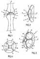
- La
figure 1 illustre un implant articulaire d'interposition conforme à l'invention mis en place entre une phalange et un métatarsien. - La
figure 2 illustre, selon une vue de profil, l'implant articulaire d'interposition conforme à l'invention. - La
figure 3 , illustre, selon une vue en perspective, l'implant articulaire d'interposition conforme à l'invention. - La
figure 4 illustre, selon une vue de dessus, une variante de réalisation de l'implant articulaire d'interposition conforme à l'invention. - La
figure 5 illustre, selon une vue de dessous, l'implant articulaire d'interposition conforme à l'invention. - Les
figures 6 et 7 illustrent, selon une vue de côté, deux variantes de réalisation de l'implant articulaire d'interposition conforme à l'invention. - Les
figures 8 et 9 illustrent, selon une vue de dessus, deux variantes de réalisation de l'implant articulaire d'interposition conforme à l'invention.
- The
figure 1 illustrates an articular implant of interposition according to the invention set up between a phalanx and a metatarsal. - The
figure 2 illustrates, in a side view, the interposition articular implant according to the invention. - The
figure 3 , illustrates, in a perspective view, the interposition articular implant according to the invention. - The
figure 4 illustrates, in a view from above, an alternative embodiment of the interposition articular implant according to the invention. - The
figure 5 illustrates, in a view from below, the interposition articular implant according to the invention. - The
Figures 6 and 7 illustrate, in a side view, two embodiments of the interposition articular implant according to the invention. - The
Figures 8 and 9 illustrate, in a view from above, two embodiments of the interposition articular implant according to the invention.
La
Plus précisément, l'implant 1 articulaire d'interposition est adapté pour être introduit au sein de l'interface articulaire 4 séparant les os 2, 3 afin de réaliser l'arthroplastie de l'articulation 5. Une arthroplastie consiste ainsi à intervenir de façon chirurgicale au niveau d'une articulation en vue de lui restituer sa mobilité. Une telle opération est notamment préconisée dans le cas où le patient souffre d'une affection chronique dégénérative des articulations, telle que l'arthrose.More specifically, the interposition
Au sens de l'invention, le terme« implant » fait référence à une pièce de préférence unique et monobloc, destinée à être implantée au sein de l'articulation en vue d'améliorer sa mobilité, et se différencie ainsi des prothèses, et notamment des prothèses articulées constituées de deux pièces, par exemple un implant métatarsien et un implant phalangien montés mobile l'un par rapport à l'autre et fixés respectivement à l'extrémité des os de l'articulation.For the purposes of the invention, the term"implant" refers to a piece of preferably single piece, intended to be implanted within the joint in order to improve its mobility, and thus differs from prostheses, including articulated prostheses consist of two parts, for example a metatarsal implant and a phalangeal implant mounted movable relative to each other and respectively fixed to the end of the bones of the joint.
L'expression« implant articulaire d'interposition » fait ainsi référence à un implant de type charnière, situé à l'interface entre deux os de manière à leur restituer leur mobilité relative.The expression"articular interposition implant" thus refers to a hinge type implant located at the interface between two bones so as to restore their relative mobility.
Afin de permettre et également de faciliter la reconstruction osseuse, il est souvent nécessaire d'immobiliser sensiblement l'implant 1, au moins temporairement, au sein de l'articulation 5. A cet effet, et selon une caractéristique essentielle de l'invention, l'implant 1 conforme à l'invention comporte des moyens d'immobilisation 6, conformés de telle sorte que lorsque l'implant 1 est disposé dans l'interface articulaire 4, les moyens d'immobilisation 6 viennent en appui contre au moins l'une des surfaces articulaires 2A, 3A. Les moyens d'immobilisation 6 assurent ainsi, par friction et adhérence sur la surface articulaire 3A, l'immobilisation automatique de l'implant 1 vis-à-vis de ladite surface articulaire 3A, et ce sans avoir recours à une broche d'ancrage ou à tout autre élément de fixation temporaire ou permanent.In order to allow and also to facilitate the bone reconstruction, it is often necessary to substantially immobilize the
Cette immobilisation spontanée concourt à l'encastrement progressif de l'implant en facilitant la régénération tissulaire qui tend au scellement de celui-ci contre la surface articulaire 3A.This spontaneous immobilization contributes to the progressive embedding of the implant by facilitating the tissue regeneration which tends to seal it against the
L'intervention chirurgicale peut comprendre une étape de préparation des surfaces articulaires, notamment de la surface 3A, voire de ménagement d'un logement, notamment dans l'os 3, pour améliorer l'assise des moyens d'immobilisation 6 et par conséquent la stabilité de l'implant. Toutefois, de façon particulièrement avantageuse, les moyens d'immobilisation 6 viennent naturellement en appui contre la surface articulaire 3A, sans qu'il soit nécessaire de réséquer ladite surface articulaire, par exemple en y ménageant des découpes planes. Les surfaces articulaires 2A, 3A des os 2, 3 étant sensiblement courbes, l'implant 1 articulaire d'interposition conforme à l'invention comporte au moins une première surface d'appui 7, et préférentiellement une première et une deuxième surface d'appui 7, 8 globalement courbes et de préférence sensiblement parallèles l'une par rapport à l'autre. De façon encore plus préférentielle, les première et deuxième surfaces d'appui 7, 8 présentent sensiblement la même courbure. Les première et deuxième surfaces d'appui 7, 8 forment ainsi avantageusement une interface de contact avec les surfaces articulaires 2A, 3A correspondantes.The surgical procedure may comprise a step of preparing the articular surfaces, in particular of the
L'expression« globalement courbe » fait référence au fait que les surfaces d'appui 7, 8, bien que susceptibles de comporter, localement, une ou plusieurs portions de surfaces planes, présentent un aspect général courbé, au moins par morceaux.The term"generally curved" refers to the fact that the bearing surfaces 7, 8, although likely to comprise, locally, one or more portions of flat surfaces, have a general aspect curved, at least in pieces.
Avantageusement, la première surface d'appui 7 est ainsi globalement convexe, la deuxième surface d'appui 8 étant globalement concave. L'implant 1 articulaire d'interposition présente ainsi une forme générale de cupule ou de demi-coque, conférant à l'implant 1 une forme anatomique lui permettant de s'adapter à la morphologie naturelle de l'articulation, et notamment à celle de l'articulation métatarso-phalangienne. Grâce à la forme anatomique de l'implant 1, il n'est alors pas nécessaire de réséquer les surfaces articulaires 2A, 3A ou les extrémités des os 2, 3.Advantageously, the
Avantageusement, les moyens d'immobilisation 6 sont solidaires de l'implant 1 et encore plus préférentiellement intégrés structurellement à l'implant 1, c'est-à-dire qu'ils ne sont ni rapportés, ni dissociés dudit implant 1. Cette caractéristique permet notamment d'immobiliser automatiquement l'implant 1 au sein de l'interface articulaire 4, dès son introduction, et donc en un nombre minimum d'étapes.Advantageously, the immobilization means 6 are integral with the
Selon l'invention, l'implant 1 s'étend, longitudinalement, c'est-à-dire selon une direction sensiblement perpendiculaire au plan d'extension radiale de l'implant, suivant un axe longitudinal X-X' qui, lorsque l'implant est en position au sein de l'interface articulaire 4, est sensiblement confondu avec l'axe des canaux médullaires des premier et deuxième os 2, 3, et par exemple du métatarsien et de la phalange correspondante.According to the invention, the
Les moyens d'immobilisation 6 sontconformés pour empêcher la rotation de l'implant 1 sur lui-même par rapport à l'axe longitudinal X-X'. Ceci permet notamment de réduire les possibilités de mobilité et de jeu de l'implant 1 au sein de l'articulation 5, susceptibles non seulement d'entraîner une gêne pour le patient, mais également de conduire à une usure progressive des surfaces articulaires 2A, 3A. L'immobilisation en rotation de l'implant 1 permet ainsi de favoriser la régénération des tissus osseux environnants.The immobilizing means 6 areconformed to prevent rotation of the
Selon une caractéristique particulièrement avantageuse de l'invention, les moyens d'immobilisation 6 sont disposés sur la première surface d'appui 7 de telle sorte que cette dernière ne présente pas une symétrie de révolution par rapport à l'axe longitudinal X-X'. Ainsi, les moyens d'immobilisation 6 sont disposés de telle sorte que la première surface d'appui 7 présente, le long d'au moins une ligne dite parallèle 9 (par analogie avec les parallèles d'une surface sphérique ou hémisphérique définis par rapport à l'équateur) située à l'intersection entre ladite première surface d'appui 7 et au moins un plan P perpendiculaire à l'axe longitudinal X-X', une courbure discontinue. En effet, contrairement aux implants de l'art antérieur, l'implant 1 conforme à l'invention ne présente pas une symétrie de révolution sur sa première surface d'appui 7.According to a particularly advantageous characteristic of the invention, the immobilization means 6 are arranged on the
En revanche, la deuxième surface d'appui 8, de préférence concave, de l'implant 1 est avantageusement sensiblement sphérique (
Les moyens d'immobilisation 6, disposés sur la première surface d'appui 7, permettent ainsi d'immobiliser sensiblement l'implant 1 vis-à-vis du deuxième os 3, favorisant ainsi la régénération osseuse. La deuxième surface d'appui 8 favorise au contraire la mobilité du premier os 2 par rapport à l'implant 1 d'une part et au deuxième os 3 d'autre part.The immobilization means 6, arranged on the
Les moyens d'immobilisation 6 peuvent cependant être disposés sur la deuxième surface d'appui 8, globalement concave, et ce sans sortir du cadre de l'invention. Dans ce cas, la première surface d'appui 7 présente un état de surface sensiblement lisse, pour permettre la mobilité du deuxième os 3, par exemple la phalange, par rapport à l'implant 1.The immobilizing means 6 may however be arranged on the second bearing surface 8, generally concave, and without departing from the scope of the invention. In this case, the
Selon l'invention telle que illustré notamment sur la
Les moyens d'immobilisation 6 pourraient, sans sortir du cadre de l'invention, également comporter une ou plusieurs faces de courbure inversée par rapport à la courbure globale de la première surface d'appui 7. Ces faces pourraient ainsi, dans le cas d'une première surface d'appui 7 globalement convexe, être formées par des faces creuses (ou concaves).The immobilizing means 6 could, without departing from the scope of the invention, also comprise one or more faces of curvature inverted with respect to the overall curvature of the
Avantageusement, les faces planes 10 présentent des aspérités (non représentées), et par exemple des stries facilitant l'accrochage et l'adhérence de l'implant 1 sur la surface articulaire 3A située en regard de la première surface d'appui 7, et donc son immobilisation en rotation relativement à ladite surface articulaire 3A. L'aspect rugueux de la première surface d'appui 7 est également de nature à favoriser la régénération osseuse du côté du deuxième os 3, c'est-à-dire, dans le cas d'une articulation métatarso-phalangienne, du côté phalangien.Advantageously, the flat faces 10 have asperities (not shown), and for example ridges facilitating the attachment and adhesion of the
Tel que cela est illustré sur la
Au sens de l'invention, l'«axe principal» Y-Y' du polyèdre s'étend entre le sommet S et la base B fictive du polyèdre (illustrée en pointillés sur la
Avantageusement, chaque face plane 10 de l'implant 1 est inclinée selon un angle α compris entre 45° et 75°, et préférentiellement de l'ordre de 60° par rapport à la l'axe principal Y-Y' du polyèdre.Advantageously, each
Tel que cela est illustré sur la
Les faces planes 10 sont préférentiellement juxtaposées de manière à présenter, deux à deux, au moins un côté commun 11. Selon une variante de réalisation illustrée sur la
Selon une variante de réalisation encore plus préférentielle de l'invention, les moyens d'immobilisation 6 sont formés par quatre faces planes 10 juxtaposées et disposées en forme de pyramide (
Cette forme particulière de l'implant 1 lui permet de pénétrer sensiblement et efficacement au sein du creux formé par la surface articulaire 3A concave.This particular form of the
Avantageusement, la première surface d'appui 7 de l'implant 1 est formée par une combinaison de faces planes 10 et de faces courbes 13 orientées dans l'espace les unes par rapport aux autres de manière à conférer à la première surface d'appui 7 une forme globalement convexe. La première surface d'appui 7 présente ainsi une pluralité de discontinuités dans sa courbure, en particulier dans un plan P sensiblement médian et perpendiculaire à l'axe longnudinal X-X de l'implant 1.Advantageously, the
Selon une variante de réalisation illustrée sur la
Selon une autre variante de réalisation illustrée sur la
L'inclinaison du polyèdre permet ainsi de reproduire la morphologie de certaines articulations, notamment les articulations métatarso-phalangiennes, pour lesquelles les os, c'est-à-dire le métatarsien et la phalange, ne sont pas nécessairement alignés mais légèrement inclinés l'un par rapport à l'autre. Ainsi, un implant 1 destiné à être positionné entre une phalange et un métatarsien du pied présentera avantageusement un dimensionnement particulier.The inclination of the polyhedron thus makes it possible to reproduce the morphology of certain articulations, in particular the metatarsophalangeal joints, for which the bones, ie the metatarsal and the phalanx, are not necessarily aligned but slightly inclined with respect to each other. Thus, an
L'implant 1 métatarso-phalangien conforme à l'invention présente ainsi, de préférence, une épaisseur moyenne de l'ordre de 4 mm mais peut également comporter des variations d'épaisseur de manière à reproduire la dorsiflexion de l'articulation 5. L'implant 1 peut ainsi se décomposer en plusieurs secteurs angulaires d'épaisseurs différentes. Dans le cas où l'implant 1 est dimensionné pour être positionné entre une phalange et un métatarsien du pied, il se décompose préférentiellement en un secteur plantaire SP, situé du côté de la plante du pied lorsqu'il est mis en place au sein de l'articulation 5, et un secteur dorsal SD, situé du côté de la partie dorsale du pied lorsque l'implant 1 est mis en place, le secteur plantaire SP présentant une épaisseur sensiblement supérieure à celle du secteur dorsal SD, de manière à reproduire l'inclinaison naturelle du métatarsien et de la phalange.The metatarso-
De façon particulièrement avantageuse, le rapport d'épaisseur entre le secteur plantaire et le secteur dorsal est compris entre 1,5 et 2,5.Particularly advantageously, the thickness ratio between the plantar sector and the dorsal sector is between 1.5 and 2.5.
L'implant 1 conforme à l'invention est en outre avantageusement dimensionné de telle manière qu'il puisse être glissé avec un faible jeu entre les surfaces articulaires 2A, 3A, de telle sorte qu'une fois positionné dans l'interface articulaire 4, l'implant 1 ne soit pas situé à distance des surfaces articulaires 2A, 3A mais au contact de ces dernières.The
Le diamètre de l'implant 1 est également ajusté au diamètre des os 2, 3 formant l'articulation, de telle sorte qu'il ne fasse, dans le pire des cas, que très légèrement saillie à l'extérieur de l'articulation 5.The diameter of the
Selon une autre caractéristique particulièrement avantageuse de l'implant 1 conforme à l'invention, et qui constitue d'ailleurs une invention à part entière, l'implant 1 comporte des moyens d'auto-centrage 14 conformés pour venir en appui contre au moins l'une des surfaces articulaires 2A, 3A, assurant ainsi le centrage diamétral automatique de l'implant 1 vis-à-vis des os 2, 3.According to another particularly advantageous characteristic of the
Les moyens d'auto-centrage sont ainsi avantageusement conformés pour faire sensiblement coïncider l'axe longitudinal X-X' central de l'implant 1 avec les axes des canaux médullaires des premier et deuxième os 2, 3.The self-centering means are thus advantageously shaped to substantially coincide the central longitudinal axis X-X 'of the
Avantageusement, les moyens d'auto-centrage 14 sont préférentiellement disposés sur la première surface d'appui 7, globalement convexe, de l'implant 1 de manière à venir en appui sur la surface articulaire 3A, sensiblement concave, du deuxième os 3.Advantageously, the self-centering
Plus précisément, les moyens d'auto-centrage 14 sont avantageusement conformés pour venir en appui sensiblement ponctuel sur la surface articulaire 3A située en regard, et pour se positionner naturellement, dans une position d'équilibre stable, dans la partie la plus profonde de la surface articulaire 3A.More precisely, the self-centering
A cet effet, les moyens d'auto-centrage 14 sont préférentiellement pourvus d'au moins une protubérance 15, telle qu'un mamelon, faisant saillie sensiblement au centre de l'implant à partir de la première surface d'appui 7 globalement convexe. La protubérance 15 est ainsi sensiblement alignée avec l'axe longitudinal X-X' central, et s'étend sensiblement dans la même direction que ce dernier.For this purpose, the self-centering
Contrairement aux implants de l'art antérieur, l'implant 1 conforme à l'invention est donc dépourvu d'orifice central et se présente avantageusement sous la forme d'un implant sensiblement plein et monobloc.Unlike implants of the prior art, the
Selon une variante préférentielle de réalisation de l'invention illustrée sur la
Tel que cela est illustré sur les
De façon préférentielle, l'implant 1 articulaire d'interposition est fabriqué, au moins partiellement, en pyrocarbone de manière à favoriser la régénération des tissus osseux. Le pyrocarbone permet ainsi, grâce à ses propriétés mécaniques sensiblement identiques à celles des tissus osseux, d'obtenir de faibles couples de friction entre l'implant 1 et les os 2, 3 formant l'articulation, limitant ainsi le phénomène de lyse osseuse.Preferably, the interposition
Toutefois, il est envisageable d'utiliser pour la fabrication de l'implant un autre matériau bio-compatible dont les propriétés mécaniques seraient adaptées à l'application décrite, notamment des céramiques ou des matériaux métalliques.However, it is conceivable to use for the manufacture of the implant another bio-compatible material whose mechanical properties would be suitable for the application described, in particular ceramics or metallic materials.
La méthode de pose de l'implant 1 conforme à l'invention va maintenant être décrite en se référant aux
La méthode chirurgicale de pose de l'implant 1 conforme à l'invention comporte tout d'abord une étape d'incision, au cours de laquelle on réalise une incision de dimensions au moins égales, et à peine supérieures à celles de l'implant 1 au niveau de l'articulation 5 de manière à permettre l'introduction de l'implant 1. Suivant le degré d'altération de l'articulation 5, le chirurgien peut éliminer ou non les irrégularités des surfaces articulaires 2A, 3A en regard, de manière à leur conférer une forme sensiblement plus lisse et arrondie.The surgical method for fitting the
La méthode chirurgicale d'arthroplastie comporte ensuite une étape (a) d'immobilisation de l'implant 1 articulaire d'interposition entre les surfaces articulaires 2A, 3A des os 2, 3, au cours de laquelle on vient directement positionner l'implant 1 dans l'interface articulaire 4 de telle sorte qu'il vienne en appui, et s'immobilise par le biais de ses propres moyens d'immobilisation 6, contre au moins l'une des surfaces articulaires 2A, 3A.The surgical method of arthroplasty then comprises a step (a) of immobilization of the
Ainsi, on immobilise l'implant sans recourir à aucun accessoire, ni organe de fixation, ni aucun moyen d'immobilisation rapporté, tel que, par exemple, une broche d'immobilisation ou de fixation.Thus, the implant is immobilized without resorting to any accessory, fastener, or attachment means, such as, for example, an immobilizing or fixing pin.
La méthode comporte en outre, avantageusement, une étape (b) d'auto-centrage de l'implant 1 au cours de laquelle on vient directement positionner l'implant 1 dans l'interface articulaire 4 de telle sorte qu'il vienne en appui, par le biais de ses propres moyens d'auto-centrage 14, contre au moins l'une des surfaces articulaires 2A, 3A, de manière à se centrer lui-même spontanément.The method also advantageously comprises a step (b) of self-centering of the
Ainsi, on réalise le centrage de l'implant intuitivement et immédiatement, sans avoir à recourir à aucun moyen de positionnement ni à aucun dispositif accessoire de centrage, tel que, par exemple, une broche de centrage.Thus, the centering of the implant is carried out intuitively and immediately, without having to resort to any positioning means or to any accessory centering device, such as, for example, a centering pin.
De façon particulièrement avantageuse, les étapes (a) d'immobilisation et (b) d'auto-centrage de l'implant 1 s'effectuent de façon simultanée.Particularly advantageously, the steps (a) of immobilization and (b) self-centering of the
Par ailleurs, lors de l'étape (b) d'auto-centrage, on vient positionner les moyens d'auto-centrage 14 de l'implant 1 en appui contre la surface articulaire 3A sensiblement concave de l'un des os 2, 3, de telle sorte que lesdits moyens d'auto-centrage 14 se positionnent naturellement dans la partie la plus profonde de la surface articulaire 3A. De cette façon, la protubérance 15 et les faces planes 10 viennent sensiblement simultanément en appui contre la surface articulaire 3A, assurant ainsi simultanément d'une part le centrage diamétral de l'implant 1 au sein de l'interface articulaire 4 et d'autre part son immobilisation en rotation, grâce notamment à l'adhérence des faces planes 10 sur la surface articulaire 3A.Moreover, during step (b) of self-centering, the self-centering
Avantageusement, après les étapes (a) d'immobilisation et (b) d'auto-centrage, on laisse reposer l'implant 1 dans l'interface articulaire 4, sans le fixer.Advantageously, after the steps (a) of immobilization and (b) of self-centering, the
La méthode chirurgicale ici décrite permet donc, à l'aide d'un seul geste, de centrer et d'immobiliser l'implant 1 au sein de l'interface articulaire 4, supprimant ainsi les étapes classiques supplémentaires de centrage et de fixation de l'implant à l'aide d'une broche.The surgical method described here thus makes it possible, by means of a single gesture, to center and immobilize the
La mise en place de l'implant 1 articulaire d'interposition conforme à l'invention ne nécessite avantageusement aucune préparation préalable des surfaces articulaires, et ne requiert en particulier aucune opération de fraisage, grâce notamment aux première et deuxième surfaces d'appui globalement courbes de l'implant 1.The placement of the
Un autre avantage de l'implant 1 conforme à l'invention est qu'il permet, grâce à la nature des matériaux le constituant mais également à sa forme anatomique et aux moyens d'immobilisation 6 intégrés structurellement à l'implant 1, de limiter le phénomène de lyse osseuse.Another advantage of the
Un autre avantage de l'implant 1 conforme à l'invention est que sa pose est rapide et s'effectue en un nombre minimum d'étapes, ce qui permet de limiter le risque de complications et d'erreurs opératoires.Another advantage of the
Claims (26)
- Articular interposition implant designed to be put in place between the articular surfaces (2A, 3A) of at least two bones (2, 3) separated by an articular interface (4) for the purpose of achieving arthroplasty of a joint (5), said implant(1) beingcharacterized in that it extends along a longitudinal axis (X-X') andin that it comprises immobilisation means (6) which comprise a plurality of essentially plane faces (10) situated on a first support surface (7) on the whole curved forming a contact interface with one of the articular surfaces (2A, 3A), and substantially inclined with respect to each other in such a way as to form a polyhedron, so that when said implant is arranged in the articular interface (4), the immobilisation means (6) are supportive of at least one of the articular surfaces (2A, 3A), to prevent rotation of said implant (1) on itself with respect to said longitudinal axis (X-X').
- Implant as claimed in claim 1,characterised in that the immobilisation means (6) are of one piece with the implant (1).
- Implant as claimed in claim 1 or 2,characterised in that it comprises at least a first support surface (7), on the whole curved, forming a contact interface with one of the articular surfaces (2A, 3A), immobilisation means (6) being arranged on said first support surface (7) in such a way that the intersection between said first support surface (7) and at least one plane (P) perpendicular to the longitudinal axis (X-X') forms a line of discontinuous curvature.
- Implant as claimed in claim 3,characterised in that immobilisation means (6) comprise at least one essentially plane surface (10) situated on said first support surface (7).
- Implant as claimed in claim 4,characterised in that said plane surface (10) is substantially inclined with respect to longitudinal axis (X-X').
- Implant as claimed in claim 4 or 5,characterised in that said plane surface (10) presents asperities, for example striae.
- Implant as claimed in one of claims 3 to 6,characterised in that it comprises a first and a second support surface (7, 8), on the whole curved and essentially parallel with respect to each other.
- Implant as claimed in claim 7,characterised in that the first support surface (7) is on the whole convex andin that the second support surface (8) is on the whole concave.
- Implant as claimed in any of the preceding claims,characterised in that it comprises a second support surface (8) essentially spherical.
- Implant as claimed in any of the preceding claims,characterised in that the angle (β) at the apex (S) of the polyhedron has a value between 90° and 150°, preferentially on the order of 120°.
- Implant as claimed in any of the preceding claims,characterised in that said plane surfaces (10) are juxtaposed in such a way as to present, two by two, at least one common side (11).
- Implant as claimed in claim 11,characterised in that it comprises, between two successive plane surfaces (10), a connecting flange (12).
- Implant as claimed in one of the preceding claims,characterised in that the immobilisation means (6) are formed by four juxtaposed plane surfaces (10) arranged in the shape of a pyramid.
- Implant as claimed in one of the preceding claims,characterised in that comprises self-centring means (14), shaped to be supportive of at least one of the articular surfaces (2A, 3A), thus ensuring automatic centring of implant (1) with respect to bones (2, 3).
- Implant as claimed in claims 14,characterised in that the self-centring means (14) are arranged on the first support surface (7).
- Implant as claimed in one of claims 14 or 15,characterised in that self-centring means (14) are provided with at least one protuberance (15), protruding essentially in the centre of implant (1).
- Implant as claimed in claims 13 and 16,characterised in that the protuberance (15) and the plane surfaces (10) are arranged in a staggered fashion, the protuberance (15) being situated essentially in the centre of the implant (1), with the plane surfaces (10) on the periphery of the implant (1).
- Implant as claimed in one of the preceding claims,characterised in that the principal axis (Y-Y') of the polyhedron is approximately coincident with the longitudinal axis (X-X').
- Implant as claimed in one of claim 1 to 17,characterised in that the principal axis (Y-Y') of the polyhedron is substantially inclined with respect to longitudinal axis (X-X').
- Implant as claimed in claim 19,characterised in that the principal axis (Y-Y') of the polyhedron is inclined by an angle (α) between 5° and 25° with respect to the longitudinal axis (X-X').
- Implant as claimed in one of the preceding claims,characterised in that the first support surface (7) of implant (1) is formed by a combination of plane surfaces (10) and curved surfaces (13), oriented in space in such a way as to confer a shape that is on the whole convex on said first support surface (7).
- Implant as claimed in one of the preceding claims,characterised in that it is, at least partially, made of pyrocarbon.
- Implant as claimed in one of the preceding claims,characterised in that it breaks down into a plantar section (SP) and a dorsal section (SD), the plantar section (SP) presenting a thickness appreciably greater than that of the dorsal section (SD).
- Implant as claimed in one of the preceding claims,characterised in that is essentially solid andin that it constitutes an implant (1) in one piece.
- Implant as claimed in one of the preceding claims,characterised in that it is dimensioned to be positioned between a phalanx and a metatarsal of the foot or hand, and thus constitutes a metatarsal-phalangeal interposition implant (1).
- Implant as claimed in one of the preceding claims,characterised in that immobilisation means (6) are shaped so as to be naturally supportive of articular surface (3A).
Applications Claiming Priority (1)
| Application Number | Priority Date | Filing Date | Title |
|---|---|---|---|
| FR0409955AFR2875398B1 (en) | 2004-09-21 | 2004-09-21 | JOINT IMPLANT OF INTERPOSITION |
Publications (3)
| Publication Number | Publication Date |
|---|---|
| EP1637095A2 EP1637095A2 (en) | 2006-03-22 |
| EP1637095A3 EP1637095A3 (en) | 2007-08-22 |
| EP1637095B1true EP1637095B1 (en) | 2012-03-21 |
Family
ID=34948823
Family Applications (1)
| Application Number | Title | Priority Date | Filing Date |
|---|---|---|---|
| EP05291953AExpired - LifetimeEP1637095B1 (en) | 2004-09-21 | 2005-09-20 | Interposition joint implant |
Country Status (3)
| Country | Link |
|---|---|
| US (1) | US20060069446A1 (en) |
| EP (1) | EP1637095B1 (en) |
| FR (1) | FR2875398B1 (en) |
Cited By (1)
| Publication number | Priority date | Publication date | Assignee | Title |
|---|---|---|---|---|
| US12440345B2 (en) | 2009-06-19 | 2025-10-14 | Tornier | Interposition implants for the hand |
Families Citing this family (15)
| Publication number | Priority date | Publication date | Assignee | Title |
|---|---|---|---|---|
| US7625408B2 (en)* | 2003-07-22 | 2009-12-01 | Avanta Orthopaedics, Llc | Prosthetic wrist implant |
| US8043375B2 (en)* | 2008-03-06 | 2011-10-25 | MoiRai Orthopaedic, LLC | Cartilage implants |
| US8012217B2 (en)* | 2008-07-03 | 2011-09-06 | Fellowship of Orthopaedic Researchers, LLC | Talar implants and methods of use |
| FR2946864B1 (en) | 2009-06-19 | 2011-07-08 | Tornier Sa | TRAPEZO-METACARPIAN JOINT IMPLANT |
| EP2687189B1 (en) | 2009-06-19 | 2015-10-14 | Tornier | Interpositional trapezium implant |
| FR2948281A1 (en) | 2009-07-23 | 2011-01-28 | Textile Hi Tec T H T | IMPLANTABLE INTERPOSITION DEVICE FOR THE REFECTION OF A PHALANGEAL OR METACARPOPHALANGIAL ARTICULATION AND SURGICAL ASSEMBLY COMPRISING SUCH A DEVICE |
| AU2010286660B2 (en) | 2009-08-25 | 2015-07-16 | Fellowship Of Orthopaedic Researchers, Inc. | Trochlear implants and methods of use |
| US8690956B2 (en) | 2010-08-23 | 2014-04-08 | Fellowship Of Orthopaedic Researchers, Inc. | Talar implants and methods of use |
| FR2973220B1 (en)* | 2011-03-29 | 2013-04-26 | Tornier Sa | METATARSIEN HEMI-ARTHROPLASTY IMPLANT |
| EP2693987A4 (en)* | 2011-04-08 | 2015-03-18 | Paragon 28 Inc | BONE IMPLANTS AND CUTTING APPARATUS AND ASSOCIATED METHODS |
| WO2012154920A1 (en) | 2011-05-12 | 2012-11-15 | Small Bone Innovations, Inc. | Wrist implant for carpal hemiarthroplasty |
| FR2975279B1 (en) | 2011-05-19 | 2014-03-28 | Tornier Sa | JOINT IMPLANT OF METATARSO-PHALANGIAN OR METACARPO-PHALANGIAN INTERPOSITION |
| US8303664B1 (en) | 2011-12-21 | 2012-11-06 | Burstein Albert H | Joint replacement spacers |
| US12290443B2 (en)* | 2020-05-01 | 2025-05-06 | Ensemble Orthopedics, Inc. | Implantable interpositional orthopedic pain management |
| US11642226B2 (en) | 2020-05-01 | 2023-05-09 | Ensemble Orthopedics, Inc. | Implantable interpositional orthopedic pain management |
Family Cites Families (28)
| Publication number | Priority date | Publication date | Assignee | Title |
|---|---|---|---|---|
| FR2470583A1 (en)* | 1979-12-07 | 1981-06-12 | Dreant Jean | Scaphoid bone flexible implant - is of silicon cpd. with spherical anchoring mass mounted centrally in flat ellipsoidal surface |
| US4936860A (en)* | 1988-09-23 | 1990-06-26 | Swanson Alfred B | Metal scaphoid implant |
| GB9015030D0 (en)* | 1990-07-07 | 1990-08-29 | Univ Strathclyde | Joint prosthesis |
| DE4140838C1 (en)* | 1991-12-11 | 1993-05-06 | Dietmar Prof. Dr. 3350 Kreiensen De Kubein-Meesenburg | |
| US5326364A (en)* | 1992-12-16 | 1994-07-05 | Wright Medical Technology, Inc. | Trapezial implant |
| US6290726B1 (en)* | 2000-01-30 | 2001-09-18 | Diamicron, Inc. | Prosthetic hip joint having sintered polycrystalline diamond compact articulation surfaces |
| US7077867B1 (en)* | 1994-08-12 | 2006-07-18 | Diamicron, Inc. | Prosthetic knee joint having at least one diamond articulation surface |
| US6494918B1 (en)* | 2000-01-30 | 2002-12-17 | Diamicron, Inc. | Component for a prosthetic joint having a diamond load bearing and articulation surface |
| US6517583B1 (en)* | 2000-01-30 | 2003-02-11 | Diamicron, Inc. | Prosthetic hip joint having a polycrystalline diamond compact articulation surface and a counter bearing surface |
| US6425922B1 (en)* | 2000-01-30 | 2002-07-30 | Diamicron, Inc. | Prosthetic hip joint having at least one sintered polycrystalline diamond compact articulation surface |
| US6596225B1 (en)* | 2000-01-31 | 2003-07-22 | Diamicron, Inc. | Methods for manufacturing a diamond prosthetic joint component |
| US6514289B1 (en)* | 2000-01-30 | 2003-02-04 | Diamicron, Inc. | Diamond articulation surface for use in a prosthetic joint |
| US5645605A (en)* | 1995-09-18 | 1997-07-08 | Ascension Orthopedics, Inc. | Implant device to replace the carpometacarpal joint of the human thumb |
| US6017366A (en)* | 1997-04-18 | 2000-01-25 | W. L. Gore & Associates, Inc. | Resorbable interposition arthroplasty implant |
| US6090145A (en)* | 1997-12-10 | 2000-07-18 | Societe Industrielle De Combustible Nucleaire S I C N | Partial scaphoid implant and method of treating ailments of the scaphoid |
| FR2794967B1 (en)* | 1999-06-21 | 2001-12-14 | Medicrea | DILATORY HEAD INTRODUCED BETWEEN BONE ARTICULAR BONE SURFACES TO RESTORE THE WIDTH AND ANGULAR POSITION |
| FR2803209B1 (en)* | 1999-12-30 | 2004-04-16 | Bioprofile | MOBILE IMPLANT BETWEEN TWO BONE SURFACES |
| FR2803191A1 (en)* | 2000-01-04 | 2001-07-06 | Bernard Wirth | Intra-articulatary surgical prosthesis has plastics cup screwed into place and formed of casing separated from multiple layer lining by fluid gap |
| US6709463B1 (en)* | 2000-01-30 | 2004-03-23 | Diamicron, Inc. | Prosthetic joint component having at least one solid polycrystalline diamond component |
| US20040199260A1 (en)* | 2000-01-30 | 2004-10-07 | Pope Bill J. | Prosthetic joint component having at least one sintered polycrystalline diamond compact articulation surface and substrate surface topographical features in said polycrystalline diamond compact |
| US6488715B1 (en)* | 2000-01-30 | 2002-12-03 | Diamicron, Inc. | Diamond-surfaced cup for use in a prosthetic joint |
| DE20003360U1 (en)* | 2000-02-24 | 2001-06-28 | König, Helmut, 34474 Diemelstadt | Joint prosthesis, especially hip joint endoprosthesis |
| FR2808994B1 (en)* | 2000-05-22 | 2003-03-21 | Transysteme Sarl | JOINT PROSTHESIS |
| DE60139262D1 (en)* | 2000-08-28 | 2009-08-27 | Disc Dynamics Inc | SYSTEM FOR RECONSTRUCTING JOINT SURFACES OF MAMMALS |
| SE525131C2 (en)* | 2001-01-15 | 2004-12-07 | Artimplant Ab | Implants for reconstruction of joints |
| JP4324478B2 (en)* | 2002-01-22 | 2009-09-02 | アドバンスト バイオ サーフェイシズ,インコーポレイティド | Interposition arthroplasty system |
| US7297146B2 (en)* | 2004-01-30 | 2007-11-20 | Warsaw Orthopedic, Inc. | Orthopedic distraction implants and techniques |
| US20060142869A1 (en)* | 2004-12-23 | 2006-06-29 | Gross Thomas P | Knee prosthesis |
- 2004
- 2004-09-21FRFR0409955Apatent/FR2875398B1/ennot_activeExpired - Fee Related
- 2005
- 2005-09-20EPEP05291953Apatent/EP1637095B1/ennot_activeExpired - Lifetime
- 2005-09-21USUS11/232,044patent/US20060069446A1/ennot_activeAbandoned
Cited By (1)
| Publication number | Priority date | Publication date | Assignee | Title |
|---|---|---|---|---|
| US12440345B2 (en) | 2009-06-19 | 2025-10-14 | Tornier | Interposition implants for the hand |
Also Published As
| Publication number | Publication date |
|---|---|
| EP1637095A3 (en) | 2007-08-22 |
| FR2875398A1 (en) | 2006-03-24 |
| EP1637095A2 (en) | 2006-03-22 |
| FR2875398B1 (en) | 2007-07-06 |
| US20060069446A1 (en) | 2006-03-30 |
Similar Documents
| Publication | Publication Date | Title |
|---|---|---|
| EP1637095B1 (en) | Interposition joint implant | |
| EP1510190B1 (en) | Glenoid component of a shoulder prosthesis and total shoulder prosthesis comprising such a component | |
| EP0127503B1 (en) | Shoulder prosthesis | |
| EP1543801B1 (en) | Shoulder or hip prostheses and method of mounting it | |
| EP2263614B1 (en) | Trapezo-metacarpal joint implant | |
| EP0299889B1 (en) | Total shoulder prosthesis | |
| EP1097680B1 (en) | Ankle prosthesis | |
| EP0201407B1 (en) | Set of parts for forming a femoral prosthesis | |
| FR2912051A1 (en) | TRAPEZO-METACARPIAN IMPLANT | |
| EP1948092B1 (en) | Implant, especially partial implant of the head of the ulna | |
| EP2603163B1 (en) | Endosseous implant having improved anchorage | |
| WO1994004100A1 (en) | Intervertebral disk prosthesis | |
| EP2444032A1 (en) | Set of glenoidal components of a shoulder prosthesis | |
| CA2354165A1 (en) | Intervertebral disc prosthesis with contact blocks | |
| FR2799116A1 (en) | Intervertebral implant comprises pure or alloyed pyrocarbon and is placed between two vertebrae and interacts by means of friction with at least one of them | |
| EP1112753B1 (en) | Mobile implant for interposition between two osseous surfaces | |
| EP2468217B1 (en) | Metatarsal hemiarthroplasty implant | |
| FR2673100A1 (en) | Wrist joint prosthesis | |
| EP2398423B1 (en) | Intervertebral disc prosthesis | |
| EP1139928A1 (en) | Total metatarsophalangeal prosthesis with section plane | |
| EP4114315B1 (en) | Acetabular implant for hip prosthesis | |
| EP1824422A2 (en) | Acetabular prosthesis to be fixed without cement | |
| EP2524671B1 (en) | Metatarsophalangeal or metacarpophalangeal joint implant | |
| FR3106271A1 (en) | IMPLANTABLE COMPONENT WITH IMPROVED ANCHORING MEDIA FOR ANKLE PROSTHESIS AND ANKLE PROSTHESIS CONSISTING OF SUCH A COMPONENT | |
| FR2960417A1 (en) | Prosthetic assembly for knee articulation of tibia during orthopedic surgery, has base plate whose peripheral edge includes material ridge for passage of nozzle of insert during installation time of insert by sliding in receiving zone |
Legal Events
| Date | Code | Title | Description |
|---|---|---|---|
| PUAI | Public reference made under article 153(3) epc to a published international application that has entered the european phase | Free format text:ORIGINAL CODE: 0009012 | |
| AK | Designated contracting states | Kind code of ref document:A2 Designated state(s):AT BE BG CH CY CZ DE DK EE ES FI FR GB GR HU IE IS IT LI LT LU LV MC NL PL PT RO SE SI SK TR | |
| AX | Request for extension of the european patent | Extension state:AL BA HR MK YU | |
| PUAL | Search report despatched | Free format text:ORIGINAL CODE: 0009013 | |
| AK | Designated contracting states | Kind code of ref document:A3 Designated state(s):AT BE BG CH CY CZ DE DK EE ES FI FR GB GR HU IE IS IT LI LT LU LV MC NL PL PT RO SE SI SK TR | |
| AX | Request for extension of the european patent | Extension state:AL BA HR MK YU | |
| 17P | Request for examination filed | Effective date:20080221 | |
| 17Q | First examination report despatched | Effective date:20080327 | |
| AKX | Designation fees paid | Designated state(s):CH DE ES FR GB IT LI | |
| GRAP | Despatch of communication of intention to grant a patent | Free format text:ORIGINAL CODE: EPIDOSNIGR1 | |
| GRAS | Grant fee paid | Free format text:ORIGINAL CODE: EPIDOSNIGR3 | |
| GRAA | (expected) grant | Free format text:ORIGINAL CODE: 0009210 | |
| AK | Designated contracting states | Kind code of ref document:B1 Designated state(s):CH DE ES FR GB IT LI | |
| RAP1 | Party data changed (applicant data changed or rights of an application transferred) | Owner name:NEWDEAL | |
| REG | Reference to a national code | Ref country code:GB Ref legal event code:FG4D Free format text:NOT ENGLISH | |
| REG | Reference to a national code | Ref country code:CH Ref legal event code:EP | |
| REG | Reference to a national code | Ref country code:DE Ref legal event code:R096 Ref document number:602005033254 Country of ref document:DE Effective date:20120516 | |
| PLBE | No opposition filed within time limit | Free format text:ORIGINAL CODE: 0009261 | |
| STAA | Information on the status of an ep patent application or granted ep patent | Free format text:STATUS: NO OPPOSITION FILED WITHIN TIME LIMIT | |
| 26N | No opposition filed | Effective date:20130102 | |
| PG25 | Lapsed in a contracting state [announced via postgrant information from national office to epo] | Ref country code:IT Free format text:LAPSE BECAUSE OF FAILURE TO SUBMIT A TRANSLATION OF THE DESCRIPTION OR TO PAY THE FEE WITHIN THE PRESCRIBED TIME-LIMIT Effective date:20120321 | |
| REG | Reference to a national code | Ref country code:DE Ref legal event code:R097 Ref document number:602005033254 Country of ref document:DE Effective date:20130102 | |
| PG25 | Lapsed in a contracting state [announced via postgrant information from national office to epo] | Ref country code:ES Free format text:LAPSE BECAUSE OF FAILURE TO SUBMIT A TRANSLATION OF THE DESCRIPTION OR TO PAY THE FEE WITHIN THE PRESCRIBED TIME-LIMIT Effective date:20120702 | |
| REG | Reference to a national code | Ref country code:CH Ref legal event code:PL | |
| PG25 | Lapsed in a contracting state [announced via postgrant information from national office to epo] | Ref country code:LI Free format text:LAPSE BECAUSE OF NON-PAYMENT OF DUE FEES Effective date:20120930 Ref country code:CH Free format text:LAPSE BECAUSE OF NON-PAYMENT OF DUE FEES Effective date:20120930 | |
| PGFP | Annual fee paid to national office [announced via postgrant information from national office to epo] | Ref country code:DE Payment date:20140822 Year of fee payment:10 | |
| PGFP | Annual fee paid to national office [announced via postgrant information from national office to epo] | Ref country code:GB Payment date:20140822 Year of fee payment:10 | |
| PGFP | Annual fee paid to national office [announced via postgrant information from national office to epo] | Ref country code:FR Payment date:20140922 Year of fee payment:10 | |
| REG | Reference to a national code | Ref country code:DE Ref legal event code:R119 Ref document number:602005033254 Country of ref document:DE | |
| GBPC | Gb: european patent ceased through non-payment of renewal fee | Effective date:20150920 | |
| REG | Reference to a national code | Ref country code:FR Ref legal event code:ST Effective date:20160531 | |
| PG25 | Lapsed in a contracting state [announced via postgrant information from national office to epo] | Ref country code:GB Free format text:LAPSE BECAUSE OF NON-PAYMENT OF DUE FEES Effective date:20150920 Ref country code:DE Free format text:LAPSE BECAUSE OF NON-PAYMENT OF DUE FEES Effective date:20160401 | |
| PG25 | Lapsed in a contracting state [announced via postgrant information from national office to epo] | Ref country code:FR Free format text:LAPSE BECAUSE OF NON-PAYMENT OF DUE FEES Effective date:20150930 |